

Page 1
Protected by copyright. Copying for private or commercial purposes, in part or in whole, is not
permitted unless authorised by AUDI AG. AUDI AG does not guarantee or accept any liability
with respect to the correctness of information in this document. Copyright by AUDI AG.
Service
Workshop Manual
Audi TT 1999 ➤
Motronic injection and ignition system (6-cyl.)
Engine ID
Edition 12.2004
BHE BPF
Service Department. Technical Information
Page 2

Protected by copyright. Copying for private or commercial purposes, in part or in whole, is not
permitted unless authorised by AUDI AG. AUDI AG does not guarantee or accept any liability
with respect to the correctness of information in this document. Copyright by AUDI AG.
Service
List of Workshop Manual Repair GroupsList of Workshop Manual
Repair GroupsList of Workshop Manual Repair Groups
Re pa ir G ro up
24 - Mixture preparation - injection
28 - Ignition system
Technical information should always be available to the foremen and mechanics, because their
careful and constant adherence to the instructions is essential to ensure vehicle road-worthiness and
safety. In addition, the normal basic safety precautions for working on motor vehicles must, as a
matter of course, be observed.
All rights reserved.
No reproduction without prior agreement from publisher.
Copyright © 2010 Audi AG, Ingolstadt A0057007220
Page 3

Protected by copyright. Copying for private or commercial purposes, in part or in whole, is not
permitted unless authorised by AUDI AG. AUDI AG does not guarantee or accept any liability
with respect to the correctness of information in this document. Copyright by AUDI AG.
Audi TT 1999 ➤
Motronic injection and ignition system (6-cyl.) - Edition 12.2004
Contents
24 - Mixture preparation - injection . . . . . . . . . . . . . . . . . . . . . . . . . . . . . . . . . . . . . . . . 1
1 Servicing Motronic injection system . . . . . . . . . . . . . . . . . . . . . . . . . . . . . . . . . . . . . . . . . . 1
1.1 Safety precautions . . . . . . . . . . . . . . . . . . . . . . . . . . . . . . . . . . . . . . . . . . . . . . . . . . . . . . . . 1
1.2 Rules for cleanliness . . . . . . . . . . . . . . . . . . . . . . . . . . . . . . . . . . . . . . . . . . . . . . . . . . . . . . 2
1.3 Technical data . . . . . . . . . . . . . . . . . . . . . . . . . . . . . . . . . . . . . . . . . . . . . . . . . . . . . . . . . . 2
1.4 Overview - fitting locations . . . . . . . . . . . . . . . . . . . . . . . . . . . . . . . . . . . . . . . . . . . . . . . . . . 3
1.5 Dismantling and assembling air cleaner . . . . . . . . . . . . . . . . . . . . . . . . . . . . . . . . . . . . . . . . 9
1.6 Intake manifold - exploded view of components . . . . . . . . . . . . . . . . . . . . . . . . . . . . . . . . 10
1.7 Removing and installing intake manifold . . . . . . . . . . . . . . . . . . . . . . . . . . . . . . . . . . . . . . 10
1.8 Wiring and component check on engine control unit with test box V.A.G 1598/31 . . . . . . 22
1.9 Removing and installing engine control unit . . . . . . . . . . . . . . . . . . . . . . . . . . . . . . . . . . . . 23
1.10 Checking system pressure, fuel pressure regulator and residual pressure . . . . . . . . . . . . 26
1.11 Dismantling and assembling fuel rail with injectors . . . . . . . . . . . . . . . . . . . . . . . . . . . . . . 30
1.12 Removing and installing injectors . . . . . . . . . . . . . . . . . . . . . . . . . . . . . . . . . . . . . . . . . . . . 30
1.13 Checking injection quantity and spray pattern of injectors; checking for leaks . . . . . . . . . . 32
1.14 Removing and installing Lambda probes (before catalytic converter) . . . . . . . . . . . . . . . . 34
1.15 Removing and installing Lambda probes (after catalytic converter) . . . . . . . . . . . . . . . . . . 36
28 - Ignition system . . . . . . . . . . . . . . . . . . . . . . . . . . . . . . . . . . . . . . . . . . . . . . . . . . . . 38
1 Checking ignition system . . . . . . . . . . . . . . . . . . . . . . . . . . . . . . . . . . . . . . . . . . . . . . . . . . 38
1.1 General notes on ignition system . . . . . . . . . . . . . . . . . . . . . . . . . . . . . . . . . . . . . . . . . . . . 38
1.2 Safety precautions . . . . . . . . . . . . . . . . . . . . . . . . . . . . . . . . . . . . . . . . . . . . . . . . . . . . . . . . 38
1.3 Technical data . . . . . . . . . . . . . . . . . . . . . . . . . . . . . . . . . . . . . . . . . . . . . . . . . . . . . . . . . . 38
1.4 Removing and installing parts of the ignition system . . . . . . . . . . . . . . . . . . . . . . . . . . . . . . 39
1.5 Removing and installing ignition coils . . . . . . . . . . . . . . . . . . . . . . . . . . . . . . . . . . . . . . . . . . 40
1.6 Removing and installing spark plugs . . . . . . . . . . . . . . . . . . . . . . . . . . . . . . . . . . . . . . . . . . 41
Contents i
Page 4

Protected by copyright. Copying for private or commercial purposes, in part or in whole, is not
permitted unless authorised by AUDI AG. AUDI AG does not guarantee or accept any liability
with respect to the correctness of information in this document. Copyright by AUDI AG.
Audi TT 1999 ➤
Motronic injection and ignition system (6-cyl.) - Edition 12.2004
ii Contents
Page 5
Protected by copyright. Copying for private or commercial purposes, in part or in whole, is not
permitted unless authorised by AUDI AG. AUDI AG does not guarantee or accept any liability
with respect to the correctness of information in this document. Copyright by AUDI AG.
Motronic injection and ignition system (6-cyl.) - Edition 12.2004
24 – Mixture preparation - injection
1 Servicing Motronic injection system
1.1 Safety precautions
To prevent injuries to persons and/or damage to the fuel injection
and ignition system, the following must be noted:
♦ Always switch off the ignition before connecting or discon‐
necting injection or ignition system wiring or tester cables.
♦ Certain tests may lead to a fault being detected by the control
unit and stored. Therefore, interrogate and, if necessary,
erase the fault memory after all repairs and tests.
♦ Always switch off the ignition before cleaning the engine.
♦ Always switch off the ignition before connecting or discon‐
necting the battery, otherwise the engine control unit may be
damaged.
Audi TT 1999 ➤
WARNING
The fuel system is pressurised. Before opening the system
place a cloth around the connection. Then dissipate pressure
by carefully unfastening the connection.
Note the following if testers and measuring instruments have to
be used during a road test:
WARNING
♦ To avoid any risk of accident, observe the following pre‐
cautions when using test instruments while road testing
the vehicle:
Audi TT Coupé:
♦ To read measured value blocks, use only the vehicle di‐
agnostic, testing and information system -VAS 5051 A- or
the vehicle diagnostic and information system VAS 5052- . Test equipment must always be secured on
the rear seat and operated from that position by a second
person.
♦ On account of the limited space available, the front pas‐
senger's seat is to be moved forwards as far as it will go
and the engaged backrest folded forwards as far as it will
go with the backrest adjuster handwheel. Do not operate
the release lever to tilt the backrest forward.
Audi TT Roadster:
♦ In the Audi TT Roadster, only use the vehicle diagnostic
and information system -VAS 5052- with the passenger's
airbag deactivated.
♦ Deactivate front passenger's airbag via the key switch in
glove box or the self-diagnosis ⇒ Body, self-diagnosis;
Rep. Gr. 01 ; Adaption .
♦ Reactivate front passenger's airbag on completion of
work.
1. Servicing Motronic injection system 1
Page 6
Protected by copyright. Copying for private or commercial purposes, in part or in whole, is not
permitted unless authorised by AUDI AG. AUDI AG does not guarantee or accept any liability
with respect to the correctness of information in this document. Copyright by AUDI AG.
Audi TT 1999 ➤
Motronic injection and ignition system (6-cyl.) - Edition 12.2004
1.2 Rules for cleanliness
When working on the fuel supply/injection system, pay careful at‐
tention to the following “6 rules”:
♦ Thoroughly clean all unions and the adjacent areas before
disconnecting.
♦ Place parts that have been removed on a clean surface and
cover them over. Do not use fluffy cloths.
♦ Carefully cover or seal open components if repairs cannot be
carried out immediately.
♦ Only install clean components; replacement parts should only
be unpacked immediately prior to installation. Do not use parts
that have been previously unpacked and stored away loose
(e.g. in toolboxes, etc.).
♦ When the system is open: Do not work with compressed air if
this can be avoided. Do not move vehicle unless absolutely
necessary.
♦ Unplugged electrical connectors; keep them clean and dry.
Make sure connections are dry when attaching.
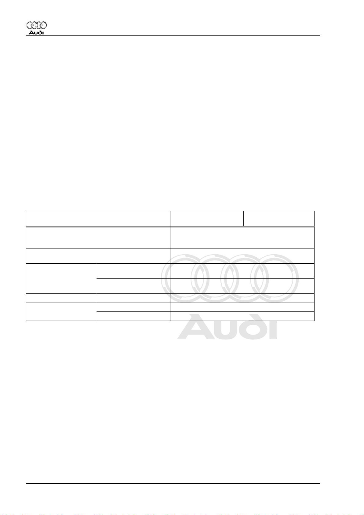
1.3 Technical data
Engine code letters BHE (3.2 ltr. / 4V / 184 kW
engine)
Idling speed
650 ... 750 rpm
1)
Cannot be adjusted; regulated by idling speed stabi‐
lisation
Speed governing by
approx. 6,500 rpm
deactivation of fuel injectors
Fuel pressure at idling
speed
Vacuum hose
connected
Vacuum hose
approx. 3.5 bar
approx. 4.0 bar
disconnected
Residual pressure after 10 minutes at least 3.0 bar
Injectors Spray pattern Two-hole nozzle / same for all injectors
1) Current values ⇒ Data sheets for exhaust emission test.
Injection quantity (30 sec.) 128 … 140 ml
BPF (3.2 ltr. / 4V / 184 kW
engine)
2 Rep. Gr.24 - Mixture preparation - injection
Page 7
Protected by copyright. Copying for private or commercial purposes, in part or in whole, is not
permitted unless authorised by AUDI AG. AUDI AG does not guarantee or accept any liability
with respect to the correctness of information in this document. Copyright by AUDI AG.
Audi TT 1999 ➤
Motronic injection and ignition system (6-cyl.) - Edition 12.2004
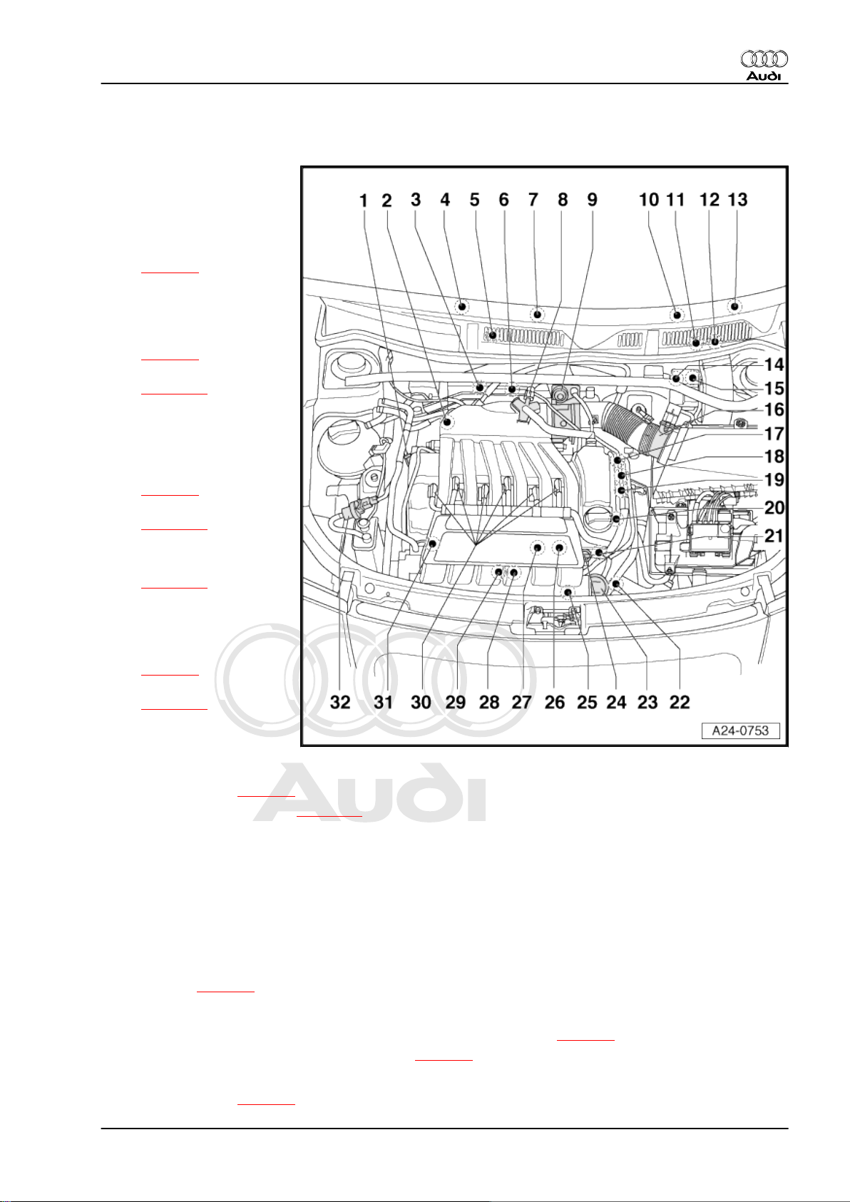
1.4 Overview - fitting locations
1 - 3-pin connector
❑ For knock sensor 1 -
G61-
2 - Knock sensor 1 -G61-
❑ Fitting location
⇒ page 8
3 - Lambda probe, before cat‐
alytic converter -G39- with
Lambda probe heater -Z19-
❑ Fitting location
⇒ page 6
❑ Removing and installing
⇒ page 34
4 - Lambda probe, after cata‐
lytic converter -G130- with
Lambda probe heater 1, after
catalytic converter -Z29-
❑ Fitting location
⇒ page 6
❑ Removing and installing
⇒ page 36
5 - Motronic control unit -J220-
❑ Removing and installing
⇒ page 23
6 - Lambda probe 2, before
catalytic converter -G108- with
Lambda probe 2 heater -Z28-
❑ Fitting location
⇒ page 6
❑ Removing and installing
⇒ page 34
7 - Lambda probe 2, after cat‐
alytic converter -G131- with
Lambda probe 2 heater, after
catalytic converter -Z30-
❑ Fitting location ⇒ page 6
❑ Removing and installing ⇒ page 36
8 - Heater element (crankcase breather) -N79-
9 - Throttle valve module -J338-
❑ Including throttle valve drive (electric throttle operation) -G186- , angle sender for throttle valve drive -
G187- and angle sender 2 for throttle valve drive -G188-
10 - Instrument cluster
❑ With exhaust emissions warning lamp -K83-
11 - Accelerator position sender -G79- and accelerator position sender 2 -G185-
Fitting location ⇒ page 5
12 - Brake light switch -F- / brake pedal switch -F47- , clutch pedal switch -F36-
❑ Fitting location of brake light switch -F- / brake pedal switch -F47- ⇒ page 5
❑ Fitting location of clutch pedal switch -F36- ⇒ page 6
13 - Fuel pump relay -J17-
❑ Fitting location ⇒ page 6
1. Servicing Motronic injection system 3
Page 8

Protected by copyright. Copying for private or commercial purposes, in part or in whole, is not
permitted unless authorised by AUDI AG. AUDI AG does not guarantee or accept any liability
with respect to the correctness of information in this document. Copyright by AUDI AG.
Audi TT 1999 ➤
Motronic injection and ignition system (6-cyl.) - Edition 12.2004
14 - Secondary air pump relay -J299-
Fitting location ⇒ page 7
15 - Motronic current supply relay -J271-
16 - Air mass meter -G70-
17 - Hall sender 2 -G163-
❑ Black connector
18 - Exhaust camshaft control valve 1 -N318-
❑ Brown connector
19 - Inlet camshaft control valve 1 -N205-
❑ Black connector
20 - Hall sender -G40-
❑ Black connector
21 - Coolant temperature sender -G62-
❑ Fitting location ⇒ page 8
❑ If necessary, release cooling system pressure before removal
22 - Engine speed sender -G28-
❑ Fitting location ⇒ page 7
23 - Vacuum unit for intake manifold change-over
24 - Fuel pressure regulator
❑ Checking ⇒ page 26
25 - Secondary air pump motor -V101-
26 - Intake manifold change-over valve -N156-
❑ Fitting location ⇒ page 7
27 - Secondary air inlet valve -N112-
❑ Fitting location ⇒ page 7
28 - Knock sensor 2 -G66-
❑ Fitting location ⇒ page 8
29 - 3-pin connector
❑ For engine speed sender -G28❑ Fitting location ⇒ page 7
30 - Ignition coils with output stages
❑ Cylinder 1 ignition coil 1 with output stage -N70❑ Cylinder 2 ignition coil 2 with output stage -N127❑ Cylinder 3 ignition coil 3 with output stage -N291❑ Cylinder 4 ignition coil 4 with output stage -N292❑ Cylinder 5 ignition coil 5 with output stage -N323❑ Cylinder 6 ignition coil 6 with output stage -N324-
31 - Injectors
❑ Cylinder 1 injector, cylinder 1 -N30❑ Cylinder 2 injector, cylinder 2 -N31❑ Cylinder 3 injector, cylinder 3 -N32❑ Cylinder 4 injector, cylinder 4 -N33❑ Cylinder 5 injector, cylinder 5 -N83❑ Cylinder 6 injector, cylinder 6 -N84❑ Checking injection quantity and spray pattern; checking for leaks ⇒ page 32
❑ Removing and installing ⇒ page 30
4 Rep. Gr.24 - Mixture preparation - injection
Page 9
Protected by copyright. Copying for private or commercial purposes, in part or in whole, is not
permitted unless authorised by AUDI AG. AUDI AG does not guarantee or accept any liability
with respect to the correctness of information in this document. Copyright by AUDI AG.
Motronic injection and ignition system (6-cyl.) - Edition 12.2004
32 - Activated charcoal filter solenoid valve 1 -N80-
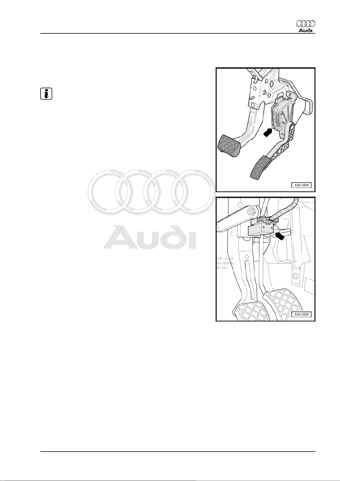
Fitting location of accelerator position sender -G79- and acceler‐
ator position sender 2 -G185-
Note
Diagram shows set-up on left-hand drive vehicles.
Audi TT 1999 ➤
Fitting location of brake light switch -F- and brake pedal switch F47-
♦ On pedal bracket
1. Servicing Motronic injection system 5
Page 10
Protected by copyright. Copying for private or commercial purposes, in part or in whole, is not
permitted unless authorised by AUDI AG. AUDI AG does not guarantee or accept any liability
with respect to the correctness of information in this document. Copyright by AUDI AG.
Audi TT 1999 ➤
Motronic injection and ignition system (6-cyl.) - Edition 12.2004
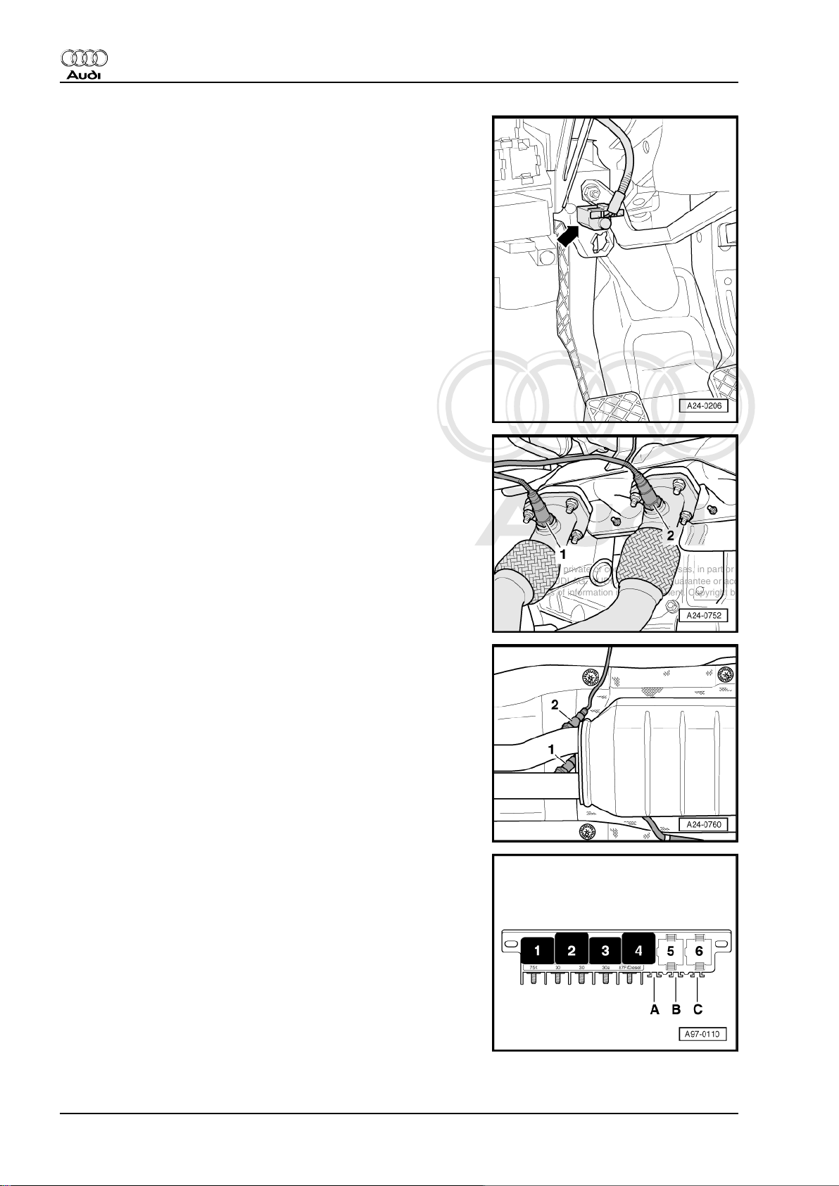
Fitting location of clutch pedal switch -F36-
♦ On pedal bracket
Fitting location of Lambda probes before catalytic converter
♦ In front exhaust pipe
1 - Lambda probe 2, before catalytic converter -G108- with
Lambda probe 2 heater -Z28-
2 - Lambda probe, before catalytic converter -G39- with Lamb‐
da probe heater -Z19-
Fitting location of Lambda probes after catalytic converter
♦ In catalytic converter
1 - Lambda probe, after catalytic converter -G130- with Lamb‐
da probe heater 1, after catalytic converter -Z29-
2 - Lambda probe 2, after catalytic converter -G131- with Lamb‐
da probe 2 heater, after catalytic converter -Z30-
Fitting location of fuel pump relay -J17-
♦ In the micro central electrics (left-side) under the dash panel:
position 4.
6 Rep. Gr.24 - Mixture preparation - injection
Page 11
Protected by copyright. Copying for private or commercial purposes, in part or in whole, is not
permitted unless authorised by AUDI AG. AUDI AG does not guarantee or accept any liability
with respect to the correctness of information in this document. Copyright by AUDI AG.
Motronic injection and ignition system (6-cyl.) - Edition 12.2004
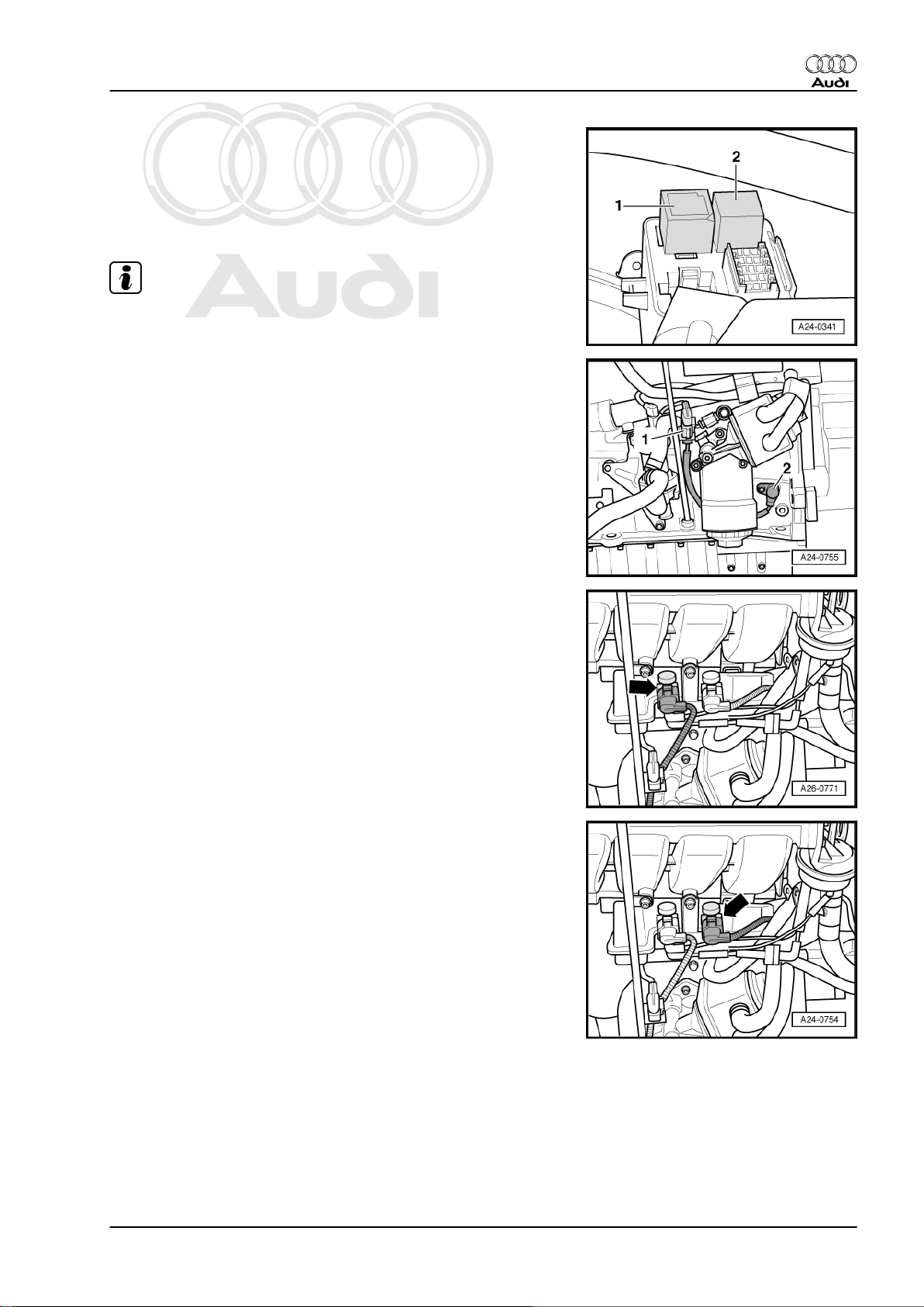
Fitting location: Motronic current supply relay -J271- and secon‐
dary air pump relay -J299-
♦ Beneath cover on left at bulkhead.
1 - Secondary air pump relay -J299-
2 - Motronic current supply relay -J271-
Note
To remove dust cover, detach relay carrier at bulkhead and lower.
Fitting location: engine speed sender -G28- with 3-pin connector
1 - 3-pin connector
2 - Engine speed sender -G28-
Audi TT 1999 ➤
Fitting location of secondary air inlet valve -N112-
♦ At vacuum reservoir (at front of engine)
Fitting location of intake manifold change-over valve -N156-
♦ At vacuum reservoir (at front of engine)
1. Servicing Motronic injection system 7
Page 12
Protected by copyright. Copying for private or commercial purposes, in part or in whole, is not
permitted unless authorised by AUDI AG. AUDI AG does not guarantee or accept any liability
with respect to the correctness of information in this document. Copyright by AUDI AG.
Audi TT 1999 ➤
Motronic injection and ignition system (6-cyl.) - Edition 12.2004
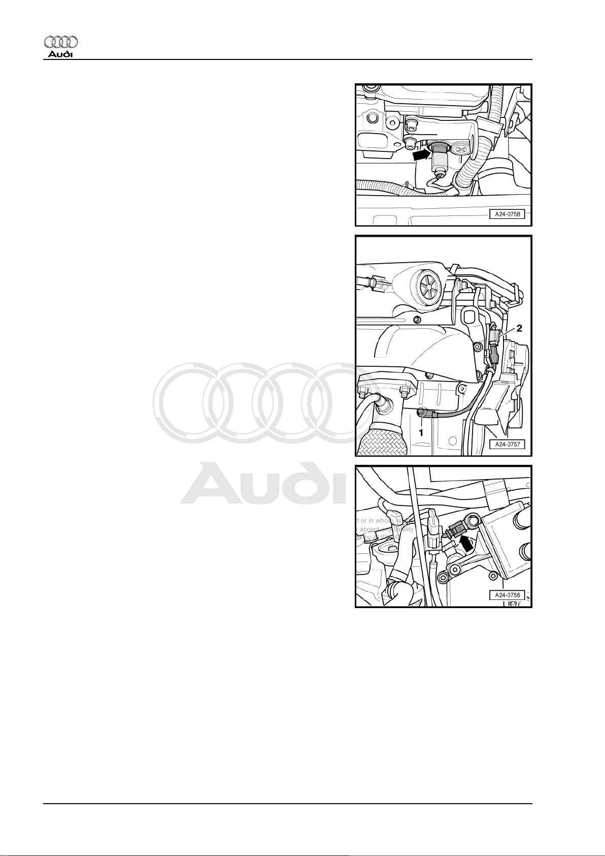
Fitting location of coolant temperature sender -G62-
♦ At front left on cylinder head
Fitting location: knock sensor 1 -G61-
♦ At rear right on cylinder block.
1 - Knock sensor 1 -G61-
2 - 3-pin connector
Fitting location: knock sensor 2 -G66-
♦ At front on cylinder block
8 Rep. Gr.24 - Mixture preparation - injection
Page 13
Protected by copyright. Copying for private or commercial purposes, in part or in whole, is not
permitted unless authorised by AUDI AG. AUDI AG does not guarantee or accept any liability
with respect to the correctness of information in this document. Copyright by AUDI AG.
Motronic injection and ignition system (6-cyl.) - Edition 12.2004
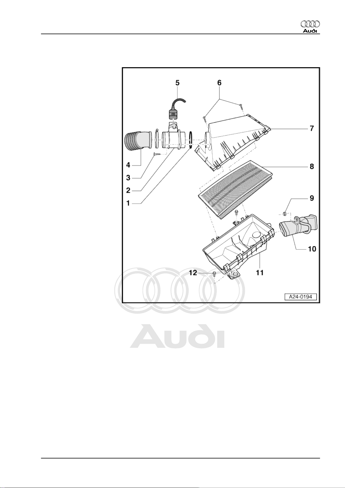
1.5 Dismantling and assembling air cleaner
1 - Seal
2 - Air mass meter -G70-
3 - Cross-head screw
4 - Air intake hose
5 - 5-pin connector
6 - Cross-head screw
7 - Air cleaner housing (top
section)
8 - Filter element
9 - Nut -10 Nm-
10 - Air intake connection
11 - Air cleaner housing (bot‐
tom section)
12 - Bolt, 10 Nm
Audi TT 1999 ➤
1. Servicing Motronic injection system 9
Page 14
Protected by copyright. Copying for private or commercial purposes, in part or in whole, is not
permitted unless authorised by AUDI AG. AUDI AG does not guarantee or accept any liability
with respect to the correctness of information in this document. Copyright by AUDI AG.
Audi TT 1999 ➤
Motronic injection and ignition system (6-cyl.) - Edition 12.2004
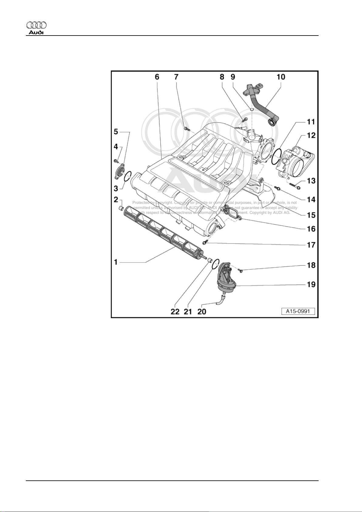
1.6 Intake manifold - exploded view of components
1 - Change-over barrel
2 - Bearing bush
3 - O-ring
❑ Renew
4 - Panel bolt
5 - Bearing cap
6 - Intake manifold
7 - 20 Nm
8 - 20 Nm
9 - Seal
10 - Connection for crankcase
breather
❑ With heater element
(crankcase breather) N79-
11 - O-ring
12 - Throttle valve module J338-
13 - 10 Nm
14 - 20 Nm
15 - Heat shield for exhaust
manifold
❑ With support for intake
manifold
16 - Gasket
❑ Renew
❑ Insert into manifold
17 - 13 Nm
18 - Panel bolt
19 - Vacuum unit
20 - Vacuum connection
❑ To intake manifold change-over valve -N156-
21 - O-ring
❑ Renew
22 - Bearing bush
1.7 Removing and installing intake manifold
Special tools and workshop equipment required
10 Rep. Gr.24 - Mixture preparation - injection
Page 15

Protected by copyright. Copying for private or commercial purposes, in part or in whole, is not
permitted unless authorised by AUDI AG. AUDI AG does not guarantee or accept any liability
with respect to the correctness of information in this document. Copyright by AUDI AG.
Motronic injection and ignition system (6-cyl.) - Edition 12.2004
♦ Drip tray for workshop hoist -VAS 6208- (TT Roadster only)
Removing
Note
All cable ties which are released or cut open when removing must
be fitted in the same position when installing.
Audi TT 1999 ➤
Caution
Observe notes on procedure for disconnecting the battery ⇒
Electrical system; Rep. Gr. 27 .
– With the ignition switched off, detach earth cable -arrow- at
battery (in luggage compartment, under floor cover).
– To remove fasteners -1- at lock carrier, press pin -2- in approx.
4 mm (do not push in completely). Then pull fastener out up‐
wards.
1. Servicing Motronic injection system 11
Page 16

Protected by copyright. Copying for private or commercial purposes, in part or in whole, is not
permitted unless authorised by AUDI AG. AUDI AG does not guarantee or accept any liability
with respect to the correctness of information in this document. Copyright by AUDI AG.
Audi TT 1999 ➤
Motronic injection and ignition system (6-cyl.) - Edition 12.2004
– Remove covers (left-side) -1- and -2- at lock carrier and above
main fuse box -arrows-.
– Remove covers (right-side) -1- and -2- at lock carrier and
above coolant expansion tank -arrows-.
– Pull out oil dipstick.
Note
Before removing, mark direction of rotation of poly V-belt with
chalk or felt-tipped pen. If the belt runs in the opposite direction
when it is refitted, this can cause breakage.
– To release tension of poly V-belt, screw a bolt M8x40
-arrow- into the bore on tensioning element.
– Remove poly V-belt from alternator pulley.
– Unscrew upper securing bolt -2- for alternator.
12 Rep. Gr.24 - Mixture preparation - injection
Page 17

Protected by copyright. Copying for private or commercial purposes, in part or in whole, is not
permitted unless authorised by AUDI AG. AUDI AG does not guarantee or accept any liability
with respect to the correctness of information in this document. Copyright by AUDI AG.
Motronic injection and ignition system (6-cyl.) - Edition 12.2004
– Unscrew upper securing bolts -upper arrows- for radiator cowl.
– Disconnect secondary air hose at the position marked with an
-arrow-.
– Move air hose clear.
Audi TT 1999 ➤
TT Coupé:
– Remove centre noise insulation -fasteners 1 ... 3-.
TT Roadster:
– Release fasteners in wheel housing (left and right)
– Unscrew bolts -arrows 1 … 3-.
Note
Disregard -arrows A and B-.
1. Servicing Motronic injection system 13
Page 18

Protected by copyright. Copying for private or commercial purposes, in part or in whole, is not
permitted unless authorised by AUDI AG. AUDI AG does not guarantee or accept any liability
with respect to the correctness of information in this document. Copyright by AUDI AG.
Audi TT 1999 ➤
Motronic injection and ignition system (6-cyl.) - Edition 12.2004
All models:
– Remove left noise insulation -arrows-.
– Remove right noise insulation -arrows-.
TT Roadster:
Note
Collect drained coolant in a clean container for re-use.
– Place drip tray for workshop hoist -VAS 6208- or -V.A.G 1306-
under engine.
– Turn drain plug -1- on radiator anti-clockwise, fit auxiliary hose
to connection if necessary.
– Remove lower coolant hose from radiator by pulling off retain‐
ing clip -2-.
All models:
– Remove tubular cross member -arrows-.
14 Rep. Gr.24 - Mixture preparation - injection
Page 19

Protected by copyright. Copying for private or commercial purposes, in part or in whole, is not
permitted unless authorised by AUDI AG. AUDI AG does not guarantee or accept any liability
with respect to the correctness of information in this document. Copyright by AUDI AG.
Motronic injection and ignition system (6-cyl.) - Edition 12.2004
– Unbolt pulley for power steering pump (counterhold with man‐
drel).
– Unscrew power steering pump from bracket -arrows-.
– Hang power steering pump on lock carrier with hydraulic ho‐
ses -1- and -2- attached.
– If fitted, unbolt bracket -2- for power steering pressure line.
– Unclip coolant hose -1-.
Audi TT 1999 ➤
– Unplug electrical connector -1- at secondary air pump motor -
V101- .
– Move wire clear.
– Unscrew bracket -2- for coolant hose.
– Unscrew bracket -3- for air filter for secondary air pump.
Note
Illustration shows vehicle with direct shift gearbox.
– Unscrew bolts -1- and -2- and remove secondary air pump with
bracket -A-.
1. Servicing Motronic injection system 15
Page 20

Protected by copyright. Copying for private or commercial purposes, in part or in whole, is not
permitted unless authorised by AUDI AG. AUDI AG does not guarantee or accept any liability
with respect to the correctness of information in this document. Copyright by AUDI AG.
Audi TT 1999 ➤
Motronic injection and ignition system (6-cyl.) - Edition 12.2004
– Detach electrical connectors -1- for radiator fans at bottom of
radiator cowl.
– Unscrew lower securing bolts -lower arrows- for radiator cowl.
– Remove the radiator cowl with both fans from below.
– Unplug electrical connector -1- for magnetic clutch of air con‐
ditioner compressor.
WARNING
The air conditioner refrigerant circuit must not be opened.
Note
The air conditioner compressor can only be removed from bracket
with upper securing bolt still inserted. To do so, press the engine
simultaneously to the left side with an assembly lever (2nd me‐
chanic is required.) If required, loosen all bolts of the assembly
mounting 1 turn.
– Unscrew bolts -arrow- for air conditioner compressor.
– Tie up air conditioner compressor together with refrigerant ho‐
ses at front of longitudinal member (refrigerant hoses remain
connected).
– Unscrew lower securing bolt -1- for alternator.
– Remove alternator from bracket for ancillary units (electrical
wires remain connected).
– Unscrew clamp -3-.
– Unscrew wire -1- at alternator.
– Detach electrical connector -2-.
– Remove alternator.
16 Rep. Gr.24 - Mixture preparation - injection
Page 21

Protected by copyright. Copying for private or commercial purposes, in part or in whole, is not
permitted unless authorised by AUDI AG. AUDI AG does not guarantee or accept any liability
with respect to the correctness of information in this document. Copyright by AUDI AG.
Motronic injection and ignition system (6-cyl.) - Edition 12.2004
– Unhook connector -arrow- for engine speed sender -G28-
from bracket on guide tube for oil dipstick.
– Unscrew bolt -3- and pull out guide tube for oil dipstick -2-.
– Unscrew bolt -4- and detach vacuum reservoir -1- from mani‐
fold.
– Move vacuum reservoir to side (hoses remain attached).
Audi TT 1999 ➤
– Unscrew bolt -arrow- at bracket for coolant pump for continued
circulation -V51- .
– Unscrew bolts -1 ... 5- and detach bracket for ancillary units.
– Unscrew bolts -arrows- at front of intake manifold.
1. Servicing Motronic injection system 17
Page 22

Protected by copyright. Copying for private or commercial purposes, in part or in whole, is not
permitted unless authorised by AUDI AG. AUDI AG does not guarantee or accept any liability
with respect to the correctness of information in this document. Copyright by AUDI AG.
Audi TT 1999 ➤
Motronic injection and ignition system (6-cyl.) - Edition 12.2004
– Detach electrical connectors at ignition coils by releasing tab
-arrow- with assembly tool -T10118- and carefully pulling con‐
nector.
– Attach puller -T10095 A- to ignition coils as shown in illustra‐
tion -arrow- and remove ignition coils one at a time.
– Remove body brace -1- -arrows-.
– Move electrical wire -arrow- clear.
– Loosen hose clips -1- and -2- and remove air hose between
air cleaner housing and throttle valve module -J338- .
18 Rep. Gr.24 - Mixture preparation - injection
Page 23

Protected by copyright. Copying for private or commercial purposes, in part or in whole, is not
permitted unless authorised by AUDI AG. AUDI AG does not guarantee or accept any liability
with respect to the correctness of information in this document. Copyright by AUDI AG.
Motronic injection and ignition system (6-cyl.) - Edition 12.2004
– Unplug electrical connectors -2- and -3-.
– Detach crankcase breather hose -1-.
– Unbolt throttle valve module -J338- from intake manifold
-arrows- and move clear to one side (coolant hoses remain
attached).
Audi TT 1999 ➤
– Disconnect vacuum hoses -1 ... 4- at rear of intake manifold.
Note
The other hoses remain attached on hose bracket.
– Unbolt hose bracket from intake manifold -arrows-.
– Remove rear securing bolts -arrows- for intake manifold.
1. Servicing Motronic injection system 19
Page 24

Protected by copyright. Copying for private or commercial purposes, in part or in whole, is not
permitted unless authorised by AUDI AG. AUDI AG does not guarantee or accept any liability
with respect to the correctness of information in this document. Copyright by AUDI AG.
Audi TT 1999 ➤
Motronic injection and ignition system (6-cyl.) - Edition 12.2004
– Protect the intake manifold from damage with a clean cloth
-1-.
– Swing the intake manifold forwards -arrow-.
Note
Cover or plug the intake ports in the cylinder head with a clean
cloth or foam plastic to prevent small items from dropping in.
– Disconnect vacuum hose -arrow- at vacuum unit for intake
manifold change-over.
20 Rep. Gr.24 - Mixture preparation - injection
Page 25

Protected by copyright. Copying for private or commercial purposes, in part or in whole, is not
permitted unless authorised by AUDI AG. AUDI AG does not guarantee or accept any liability
with respect to the correctness of information in this document. Copyright by AUDI AG.
Motronic injection and ignition system (6-cyl.) - Edition 12.2004
– Unclip pipe guide -1- from fuel rail -2-.
– Disconnect vacuum pipe -3- from fuel pressure regulator.
– Unscrew bolts -arrows-.
– Remove fuel rail with fuel injectors from cylinder head and
move clear to one side (fuel lines remain attached).
– Swing intake manifold back to its fitting position and remove.
Installing
Installation is carried out in the reverse order; note the following:
Note
Renew gaskets.
– Install bracket for ancillary units ⇒ 6-cylinder engine, me‐
chanics; Rep. Gr. 13
– Drive back the respective bushes for securing bolts slightly to
facilitate installation of power steering pump, alternator and air
conditioner compressor.
– Install alternator ⇒ Electrical system; Rep. Gr. 27
– Install air conditioner compressor ⇒ Air conditioning system;
Rep. Gr. 87
– Install radiator cowl ⇒ 6-cylinder engine, mechanics; Rep. Gr.
19
– Install secondary air pump ⇒ 6-cylinder engine, mechanics;
Rep. Gr. 26
– Install power steering pump ⇒ Running gear, front-wheel drive
and four-wheel drive; Rep. Gr. 48 .
– Install body brace ⇒ Running gear, front-wheel drive and four-
wheel drive; Rep. Gr. 40 .
– Install tubular cross member ⇒ General body repairs, exterior;
Rep. Gr. 50 .
– Install poly V-belt ⇒ 6-cylinder engine, mechanics; Rep. Gr.
13
– Install noise insulation panels ⇒ General body repairs, exte‐
rior; Rep. Gr. 50 .
– Connect earth strap to battery ⇒ Electrical system; Rep. Gr.
27 .
Audi TT 1999 ➤
– Engine mountings must be adjusted (⇒ 6-cylinder engine,
mechanics; Rep. Gr. 10 ) if bolts for assembly mounting were
loosened.
TT Roadster:
– Fill cooling system ⇒ 6-cylinder engine, mechanics; Rep. Gr.
19 .
1. Servicing Motronic injection system 21
Page 26

Protected by copyright. Copying for private or commercial purposes, in part or in whole, is not
permitted unless authorised by AUDI AG. AUDI AG does not guarantee or accept any liability
with respect to the correctness of information in this document. Copyright by AUDI AG.
Audi TT 1999 ➤
Motronic injection and ignition system (6-cyl.) - Edition 12.2004
Tightening torques
Component Nm
Intake manifold to cylinder head 13
Bracket for coolant pump for continued circula‐
tion -V51- to cylinder block
Intake manifold support to intake manifold 20
Throttle valve module -J338- to intake manifold 10
Vacuum reservoir to intake manifold 5
Guide tube for oil dipstick to intake manifold 5
20
1.8 Wiring and component check on engine
control unit with test box V.A.G 1598/31-
Special tools and workshop equipment required
♦ Test box -V.A.G 1598/31-
Note
♦
The test box -V.A.G 1598/31- is designed so that it can be
connected both to the wiring harness for the engine control
unit and to the engine control unit itself at the same time.
♦
The advantage of this is that the electronic engine control sys‐
tem remains fully functional when the test box is connected
(for example, for measuring signals when the engine is run‐
ning).
♦
The instructions for performing the individual tests indicate
whether or not the engine control unit itself also needs to be
connected to the test box.
♦
Always use adapter set -V.A.G 1594 A- to connect test equip‐
ment (e.g. voltage tester -V.A.G 1527 B- , hand-held multime‐
ter -V.A.G 1526 A- etc.).
Procedure
– Remove engine control unit ⇒ page 23 .
Note
If the test box -V.A.G 1598/31- only needs to be attached to the
81-pin connector, the protective housing for the engine control
unit does not need to be removed.
22 Rep. Gr.24 - Mixture preparation - injection
Page 27

Protected by copyright. Copying for private or commercial purposes, in part or in whole, is not
permitted unless authorised by AUDI AG. AUDI AG does not guarantee or accept any liability
with respect to the correctness of information in this document. Copyright by AUDI AG.
Motronic injection and ignition system (6-cyl.) - Edition 12.2004
– Connect test box -V.A.G 1598/31- to connectors on wiring
harness.
– Connect earth clip of test box to earth -arrow-.
– The instructions for performing the individual tests indicate
whether or not the engine control unit itself also needs to be
connected to the test box.
– Carry out test as described in relevant repair procedures.
– After completing test, re-install engine control unit
⇒ page 23 .
1.9 Removing and installing engine control unit
The 60-pin connector of engine control unit -1- is equipped with
a protective housing -4- that is secured with a locking plate -2and shear bolts -3-. To make it more difficult to unscrew the shear
bolts, the threads have additionally been coated with locking fluid.
The protective housing has to be removed before the 60-pin con‐
nector can be unplugged from the engine control unit (e.g. to
connect test box or replace engine control unit).
Audi TT 1999 ➤
Special tools and workshop equipment required
♦ Hot air blower (from wiring harness repair set -VAS 1978- )
♦ Nozzle for hot air blower from the wiring harness repair set -
VAS 1978-
♦ Vice-grip pliers (commercially available)
Removing
– When replacing engine control unit, select diagnosis object
“Renew engine control unit” in “Guided Fault Finding”.
For this purpose, use vehicle diagnostic, testing and information
system -5051 A- .
– Switch off ignition and remove ignition key.
1. Servicing Motronic injection system 23
Page 28

Protected by copyright. Copying for private or commercial purposes, in part or in whole, is not
permitted unless authorised by AUDI AG. AUDI AG does not guarantee or accept any liability
with respect to the correctness of information in this document. Copyright by AUDI AG.
Audi TT 1999 ➤
Motronic injection and ignition system (6-cyl.) - Edition 12.2004
– Use screwdriver to pry off caps on wiper arms -arrows- and
slacken off hexagon nuts several turns.
– Detach wiper arms from wiper shafts by moving them slightly
backwards and forwards.
– Completely unscrew hexagon nuts and remove wiper arms.
– Pull off rubber seal -1- on plenum chamber cover.
– Detach plenum chamber cover -2- and lay aside (towards
windscreen).
– Detach electrical connectors for windscreen washer heating.
– Unclip cover -2-.
– Detach 81-pin connector -1- at engine control unit.
– Release retaining tab -arrow- and pull engine control unit for‐
wards out of the bracket.
Note
♦
The 60-pin connector -3- is secured with the protective hous‐
ing and remains attached when removing engine control unit.
♦
When the engine control unit is disconnected, the learnt values
are erased but the contents of the fault memory remain intact.
Caution
The following procedure must be followed exactly to prevent
any damage (burning) to wiring, connectors, insulation and
control units. Observe operating instructions for hot air blower.
24 Rep. Gr.24 - Mixture preparation - injection
Page 29

Protected by copyright. Copying for private or commercial purposes, in part or in whole, is not
permitted unless authorised by AUDI AG. AUDI AG does not guarantee or accept any liability
with respect to the correctness of information in this document. Copyright by AUDI AG.
Motronic injection and ignition system (6-cyl.) - Edition 12.2004
– Select settings on hot-air blower as shown in illustration, i.e.
set temperature potentiometer -2- to maximum heat output
and two-stage air flow switch -3- to position “3”.
Note
Then use hot air blower to heat threaded holes in protective hous‐
ing into which shear bolts have been screwed. This step reduces
inhibiting action of locking fluid on shear bolt thread and makes it
easier to unscrew these bolts.
– Place the engine control unit on a heat-resistant surface (con‐
nectors remain attached).
Caution
The shear bolts and protective housing also become very hot
when heating the threads of the locking mechanism. Take care
to avoid burns. It is also important to ensure that only the thread
is heated and none of the surrounding components if at all
possible. These should be covered if necessary.
Audi TT 1999 ➤
– Direct nozzle -1- of hot air blower at bolt -2- of locking mech‐
anism. You can rest the nozzle on the top section of the
protective housing.
– Switch on the hot air blower and heat the thread for approxi‐
mately 20 to 25 seconds.
1. Servicing Motronic injection system 25
Page 30

Protected by copyright. Copying for private or commercial purposes, in part or in whole, is not
permitted unless authorised by AUDI AG. AUDI AG does not guarantee or accept any liability
with respect to the correctness of information in this document. Copyright by AUDI AG.
Audi TT 1999 ➤
Motronic injection and ignition system (6-cyl.) - Edition 12.2004
– Grasp head of bolt -2- with vice-grip pliers -1- and unscrew
shear bolt -arrows-.
– Repeat the procedure for the 2nd shear bolt.
Note
Be particularly careful here, as this shear bolt is in the immediate
vicinity of control unit connector.
– Release the retaining tab and detach the 60-pin connector for
engine control unit.
Installing
Installation is carried out in the reverse order; note the following:
– Reinstall the engine control unit into the protective housing.
– Clean threaded holes for shear bolts to remove any residue
from locking fluid. This can be done by using a thread tap.
– Use new shear bolts.
After installing a new engine control unit, the following operations
must be performed:
– Activate engine control unit in “Guided Fault Finding” under
diagnosis option “Replace engine control unit”.
For this purpose, use vehicle diagnostic, testing and information
system -VAS 5051 A- .
1.10 Checking system pressure, fuel pres‐
sure regulator and residual pressure
Fuel pressure is controlled by the fuel pressure regulator accord‐
ing to the intake manifold pressure. As a result, the pressure drop
at the injectors remains constant at all engine speeds and throttle
openings.
26 Rep. Gr.24 - Mixture preparation - injection
Page 31

Protected by copyright. Copying for private or commercial purposes, in part or in whole, is not
permitted unless authorised by AUDI AG. AUDI AG does not guarantee or accept any liability
with respect to the correctness of information in this document. Copyright by AUDI AG.
Special tools and workshop
equipment required
♦ K-Jetronic pressure gauge
-V.A.G 1318-
♦ Adapter set -
V.A.G 1318/17-
♦ Hose clip pliers -
V.A.G 1921-
Audi TT 1999 ➤
Motronic injection and ignition system (6-cyl.) - Edition 12.2004
Test requirements
• Fuel pump relay OK.
• Fuel pump OK; checking: ⇒ Fuel supply system, petrol en‐
gines; Rep. Gr. 20 .
• Fuel filter OK
• Battery voltage at least 12.5 V
Checking system pressure
– Briefly open the fuel tank filler cap (to release pressure).
– Open cover of fuse holder and remove fuse 28 for fuel system
pressurisation pump -G6- .
WARNING
The fuel system is pressurised. Before opening the system
place a clean cloth around the connection. Then dissipate
pressure by carefully unfastening the connection.
1. Servicing Motronic injection system 27
Page 32

Protected by copyright. Copying for private or commercial purposes, in part or in whole, is not
permitted unless authorised by AUDI AG. AUDI AG does not guarantee or accept any liability
with respect to the correctness of information in this document. Copyright by AUDI AG.
Audi TT 1999 ➤
Motronic injection and ignition system (6-cyl.) - Edition 12.2004
– Disconnect fuel supply pipe -1- by pressing release tab.
– Connect K-Jetronic pressure gauge -V.A.G 1318- with adapt‐
ers -V.A.G 1318/9- and -V.A.G 1318/17- to fuel supply pipe.
– Open cut-off valve on pressure gauge.
• Lever must point in direction of flow.
– Re-insert fuse 28 for fuel system pressurisation pump -G6- in
the fuse holder.
– Start the engine and run at idling speed.
– Measure the fuel pressure.
• Specification: approx. 3.5 bar
– Disconnect vacuum hose at fuel pressure regulator.
• Fuel pressure must increase to approx. 4.0 bar.
– Switch off ignition.
Checking for leakage and checking residual pressure
– Check leak-tightness and residual pressure by watching the
drop in pressure on the pressure gauge.
• After 10 minutes pressure must still be at least 3.0 bar.
If the residual pressure drops below 3.0 bar:
– Start the engine and run at idling speed.
28 Rep. Gr.24 - Mixture preparation - injection
Page 33

Protected by copyright. Copying for private or commercial purposes, in part or in whole, is not
permitted unless authorised by AUDI AG. AUDI AG does not guarantee or accept any liability
with respect to the correctness of information in this document. Copyright by AUDI AG.
Motronic injection and ignition system (6-cyl.) - Edition 12.2004
– Allow pressure to build up, then switch off ignition. At the same
time, close cut-off valve of K-Jetronic pressure gauge V.A.G 1318- (so that lever is perpendicular to direction of flow
-arrow-).
– Observe pressure drop on pressure gauge.
If the pressure now does not drop:
– Check fuel pump non-return valve
If the pressure drops again:
– Open cut-off valve on pressure gauge (lever points in direction
of flow).
– Start the engine and run at idling speed.
– Allow pressure to build up, then switch off ignition. At the same
time tightly clamp-off the return hose (with blue marking).
If the pressure now does not drop:
– Renew the fuel pressure regulator.
If the pressure drops again:
– Check pipe connections, O-rings on fuel rail and injectors for
leaks.
– Check pressure gauge for leaks.
Audi TT 1999 ➤
Note
Before removing the pressure gauge, release the fuel pressure
by opening the cut-off valve. Hold a container under the connec‐
tion.
1. Servicing Motronic injection system 29
Page 34

Protected by copyright. Copying for private or commercial purposes, in part or in whole, is not
permitted unless authorised by AUDI AG. AUDI AG does not guarantee or accept any liability
with respect to the correctness of information in this document. Copyright by AUDI AG.
Audi TT 1999 ➤
Motronic injection and ignition system (6-cyl.) - Edition 12.2004
1.11 Dismantling and assembling fuel rail with injectors
1 - Fuel return hose
2 - Fuel supply hose
3 - Fuel rail
4 - Hexagon socket head bolt,
10 Nm
5 - Fuel pressure regulator
6 - O-ring
7 - O-ring
8 - Retaining clip
❑ Check for correct fit on
fuel rail
9 - O-ring
❑ Removing and installing
⇒ page 30
❑ Renew
❑ Lubricate with clean en‐
gine oil
10 - Retaining clip
❑ Check for correct fit on
injector
11 - O-ring
❑ Removing and installing
⇒ page 30
❑ Renew
❑ Lubricate with clean en‐
gine oil
12 - Injector
1.12 Removing and installing injectors
Removing
– Remove intake manifold ⇒ page 10 .
WARNING
The fuel system is pressurised. Before opening the system
place a cloth around the connection. Then dissipate pressure
by carefully unfastening the connection.
30 Rep. Gr.24 - Mixture preparation - injection
Page 35

Protected by copyright. Copying for private or commercial purposes, in part or in whole, is not
permitted unless authorised by AUDI AG. AUDI AG does not guarantee or accept any liability
with respect to the correctness of information in this document. Copyright by AUDI AG.
Motronic injection and ignition system (6-cyl.) - Edition 12.2004
– Disconnect fuel supply pipe -1- and fuel return pipe -2- by
pressing release tabs.
– Remove fuel rail together with injectors ⇒ page 30 . Fuel hoses
remain connected.
– Pull off retaining clip and detach injector.
Note
The fuel hoses must be detached before replacing fuel rail.
Installing
Installation is carried out in the reverse order; note the following:
• Renew the O-rings at all opened connections. (When renew‐
ing the front O-ring, ensure that the plastic cap is not removed
from the injector head. The O-ring must be pulled off over the
plastic cap).
• Lubricate the O-rings with clean engine oil.
• Make sure injectors are installed in correct position.
• Make sure retaining clips are properly connected.
• Position fuel rail with secured injectors on intake manifold and
press evenly into place.
Tightening torque
Audi TT 1999 ➤
Component Nm
Fuel rail to intake manifold 10
1. Servicing Motronic injection system 31
Page 36

Protected by copyright. Copying for private or commercial purposes, in part or in whole, is not
permitted unless authorised by AUDI AG. AUDI AG does not guarantee or accept any liability
with respect to the correctness of information in this document. Copyright by AUDI AG.
Audi TT 1999 ➤
Motronic injection and ignition system (6-cyl.) - Edition 12.2004
1.13 Checking injection quantity and spray pattern of injectors; checking for leaks
Special tools and workshop
equipment required
♦ Remote control -
V.A.G 1348/3 A- with
adapter cable V.A.G 1348/3 - 2-
♦ Adapter set -V.A.G 1594 A-
♦ Injection rate tester -
V.A.G 1602-
♦ Test box -V.A.G 1598/31-
Test requirements
• Fuel pressure OK; testing ⇒ page 26
Test sequence
– Remove intake manifold ⇒ page 10 .
– Remove fuel rail together with injectors ⇒ page 30 . Fuel hoses
remain connected.
32 Rep. Gr.24 - Mixture preparation - injection
Page 37

Protected by copyright. Copying for private or commercial purposes, in part or in whole, is not
permitted unless authorised by AUDI AG. AUDI AG does not guarantee or accept any liability
with respect to the correctness of information in this document. Copyright by AUDI AG.
Motronic injection and ignition system (6-cyl.) - Edition 12.2004
Checking for leaks
– Open cover of fuse holder and remove fuse 28 for fuel system
pressurisation pump -G6- .
– Connect remote control -V.A.G 1348/3 A- with adapter cable
-V.A.G 1348/3 - 2- to contact 28a for fuel pump and to the
positive (+) battery terminal.
– Connect battery earth cable.
– Activate the remote control -V.A.G 1348/3 A- .
• The fuel pump should run.
– Visually check the fuel injectors for leaks.
• When the fuel pump is running, no more than 1 to 2 drops a
minute should escape from any one of the injectors.
If the fuel loss is greater:
– Renew defective fuel injector ⇒ page 30 .
Checking injection quantity
– Connect test box -V.A.G 1598/31- to wiring harness for engine
control unit ⇒ page 22 . The engine control unit is not connec‐
ted.
– Use leads from adapter set -V.A.G 1594 A- to bridge contacts
1 and 65 at test box.
Audi TT 1999 ➤
– Detach electrical connectors for fuel injectors by pressing re‐
taining tab in the direction of the -arrow-.
– Place a fuel injector in a measuring glass for injection rate
tester -V.A.G 1602- .
1. Servicing Motronic injection system 33
Page 38

Protected by copyright. Copying for private or commercial purposes, in part or in whole, is not
permitted unless authorised by AUDI AG. AUDI AG does not guarantee or accept any liability
with respect to the correctness of information in this document. Copyright by AUDI AG.
Audi TT 1999 ➤
Motronic injection and ignition system (6-cyl.) - Edition 12.2004
– Connect one of the contacts of fuel injector to engine earth
using test lead and crocodile clamp from adapter set V.A.G 1594 A- .
– Connect second contact of fuel injector to remote control -
V.A.G 1348/3 A- using adapter cable -V.A.G 1348/3 - 2- .
– Connect crocodile clamp to positive (+) battery terminal.
– Use leads from adapter set -V.A.G 1594 A- to bridge contacts
1 and 65 at test box.
– If necessary, connect battery earth cable.
– Switch on ignition.
• The fuel pump should run.
– Press the remote control -V.A.G 1348/3 A- for 30 seconds.
– Carry out test for all fuel injectors using a new test glass each
time.
Note
Also check the spray pattern when testing the injection rate. The
spray pattern should be the same for all injectors.
– Once all 6 injectors have been actuated, place measuring
glasses on a level surface.
• Specification: 128 ... 140 ml for each injector
If the measured values for one or more of the fuel injectors do not
meet the specification:
– Switch off the fuel pump (switch off the ignition) and renew the
faulty injector ⇒ page 30 .
If the measured values for all the injectors are outside the speci‐
fication:
– Check fuel pressure ⇒ page 26 .
– Install injectors together with fuel rail ⇒ page 31 .
1.14 Removing and installing Lambda probes (before catalytic converter)
Special tools and workshop equipment required
♦ Lambda probe open ring spanner set -3337-
34 Rep. Gr.24 - Mixture preparation - injection
Page 39

Protected by copyright. Copying for private or commercial purposes, in part or in whole, is not
permitted unless authorised by AUDI AG. AUDI AG does not guarantee or accept any liability
with respect to the correctness of information in this document. Copyright by AUDI AG.
Motronic injection and ignition system (6-cyl.) - Edition 12.2004
Removing
– Remove body brace -1- -arrows-.
– Loosen the Lambda probe that is to be removed about 1 turn
(accessible from above).
1 - Lambda probe 2, before catalytic converter -G108- with
Lambda probe 2 heater -Z28-
2 - Lambda probe, before catalytic converter -G39- with Lamb‐
da probe heater -Z19-
Audi TT 1999 ➤
– Remove centre noise insulation -fasteners 1 ... 3-.
– Unbolt the protective cover -arrows-.
– Detach electrical connector for Lambda probe (before catalytic
converter) that is to be removed and move clear to side.
1. Servicing Motronic injection system 35
Page 40

Protected by copyright. Copying for private or commercial purposes, in part or in whole, is not
permitted unless authorised by AUDI AG. AUDI AG does not guarantee or accept any liability
with respect to the correctness of information in this document. Copyright by AUDI AG.
Audi TT 1999 ➤
Motronic injection and ignition system (6-cyl.) - Edition 12.2004
– Unscrew the Lambda probe (before catalytic converter) from
below; ensure that the electrical wire is not damaged when
unscrewing.
1 - Lambda probe 2, before catalytic converter -G108- with
Lambda probe 2 heater -Z28-
2 - Lambda probe, before catalytic converter -G39- with Lamb‐
da probe heater -Z19-
Installing
Installation is carried out in the reverse order; note the following:
Note
♦
Threads of new Lambda probes are already coated with as‐
sembly paste; the paste must not get into the slots on the probe
body.
♦
If reinstalling the old Lambda probes, coat the threads with
high-temperature paste ⇒ Parts catalogue . The paste must
not get into the slots on the probe body.
♦
When installing, the Lambda probe wire must always be reat‐
tached at the same locations to prevent it from coming into
contact with the exhaust pipe.
♦
Secure the heat insulation sleeves in the original position
when installing.
Tightening torques
Component Nm
Lambda probe (before catalytic converter) in
front exhaust pipe
Body brace to body / bracket 20
55
1.15 Removing and installing Lambda probes (after catalytic converter)
Special tools and workshop equipment required
♦ Lambda probe open ring spanner set -3337-
36 Rep. Gr.24 - Mixture preparation - injection
Page 41

Protected by copyright. Copying for private or commercial purposes, in part or in whole, is not
permitted unless authorised by AUDI AG. AUDI AG does not guarantee or accept any liability
with respect to the correctness of information in this document. Copyright by AUDI AG.
Motronic injection and ignition system (6-cyl.) - Edition 12.2004
Removing
– Unbolt the protective cover -arrows-.
– Detach the electrical connector for the Lambda probe (after
catalytic converter) that is to be removed, and move the con‐
nector clear.
Lambda probe (right-side):
– Unscrew wire guide -arrows-.
Audi TT 1999 ➤
Continuation for both sides:
– Unscrew the Lambda probe (after catalytic converter); ensure
that the electrical wire is not damaged when unscrewing.
1 - Lambda probe 2, after catalytic converter -G131- with Lamb‐
da probe 2 heater, after catalytic converter -Z30-
2 - Lambda probe, after catalytic converter -G130- with Lamb‐
da probe heater 1, after catalytic converter -Z29-
Installing
Installation is carried out in the reverse order; note the following:
Note
♦
Threads of new Lambda probes are already coated with as‐
sembly paste; the paste must not get into the slots on the probe
body.
♦
If reinstalling the old Lambda probes, coat the threads with
high-temperature paste ⇒ Parts catalogue . The paste must
not get into the slots on the probe body.
♦
When installing, the Lambda probe wire must always be reat‐
tached at the same locations to prevent it from coming into
contact with the exhaust pipe.
Tightening torque
Component Nm
Lambda probe (after catalytic converter) in cat‐
55
alytic converter
1. Servicing Motronic injection system 37
Page 42

Protected by copyright. Copying for private or commercial purposes, in part or in whole, is not
permitted unless authorised by AUDI AG. AUDI AG does not guarantee or accept any liability
with respect to the correctness of information in this document. Copyright by AUDI AG.
Audi TT 1999 ➤
Motronic injection and ignition system (6-cyl.) - Edition 12.2004
28 – Ignition system
1 Checking ignition system
1.1 General notes on ignition system
♦ Always switch off the ignition before connecting or discon‐
necting the battery, otherwise the engine control unit may be
damaged.
♦ A voltage of at least 12.7 V is required for proper operation of
electrical components.
♦ Certain tests may lead to a fault being detected by the control
unit and stored. The fault memory should therefore be inter‐
rogated and (if necessary) erased after completing the tests
and any repair work that may be required.
♦ If the engine starts, runs for a short period and then cuts out
after completing fault finding, repairs or component tests, this
may be due to the immobiliser disabling the engine control
unit. The fault memory must then be interrogated and, if nec‐
essary, the control unit must be adapted.
1.2 Safety precautions
Note the following to avoid injuries or damage to the fuel injection
system or ignition system:
♦ Do not touch or detach the ignition wires when the engine is
running or while starting the engine.
♦ The ignition must be switched off before disconnecting or con‐
necting ignition system wiring, high-voltage wires and test
leads.
♦ Certain tests may lead to a fault being detected by the control
unit and stored. Therefore, interrogate and, if necessary,
erase the fault memory after all repairs and tests.
♦ Always switch off the ignition before cleaning the engine.
1.3 Technical data
Engine code letters BHE (3.2 ltr. / 4V / 184 kW
engine)
Idling speed
Cannot be adjusted; regulated by idling speed stabili‐
sation
Speed governing by
deactivation of fuel injectors
Ignition timing
Not adjustable (determined by control unit)
Ignition system Multi-coil system with 6 ignition coils (output stages in‐
tegrated) connected directly to spark plugs via spark
Spark plugs
Firing order 1-5-3-6-2-4
2)
650 ... 750 rpm
approx. 6,500 rpm
plug connectors
Tightening torque 30 Nm
BPF (3.2 ltr. / 4V / 184 kW
engine)
2)
2) Current values ⇒ Data sheets for exhaust emission test.
38 Rep. Gr.28 - Ignition system
Page 43

Protected by copyright. Copying for private or commercial purposes, in part or in whole, is not
permitted unless authorised by AUDI AG. AUDI AG does not guarantee or accept any liability
with respect to the correctness of information in this document. Copyright by AUDI AG.
Audi TT 1999 ➤
Motronic injection and ignition system (6-cyl.) - Edition 12.2004
1.4 Removing and installing parts of the ignition system
1 - Ignition coils with output
stages
❑ Cylinder 1 ignition coil 1
with output stage -N70-
❑ Cylinder 2 ignition coil 2
with output stage N127-
❑ Cylinder 3 ignition coil 3
with output stage N291-
❑ Cylinder 4 ignition coil 4
with output stage N292-
❑ Cylinder 5 ignition coil 5
with output stage N323-
❑ Cylinder 6 ignition coil 6
with output stage N324-
❑ Removing and installing
⇒ page 40
2 - 4-pin connector
❑ For ignition coils with
output stage
3 - Bracket
❑ For connector for knock
sensor 1 -G61-
4 - Bolt, 10 Nm
5 - 3-pin connector
❑ Black
❑ With gold-plated con‐
tacts
6 - Knock sensor 1 -G61-
7 - Bolt, 20 Nm
❑ To ensure correct operation of the knock sensor, it is important to adhere to the specified tightening
torque.
8 - Camshaft adjuster
❑ Exhaust side
❑ With sender wheel for Hall sender 2 -G163❑ After reinstalling, adjust valve timing ⇒ 6-cylinder engine, mechanics; Rep. Gr. 13
9 - Cover (upper) for camshaft timing chain
❑ Removing and installing ⇒ 6-cylinder engine, mechanics; Rep. Gr. 13
10 - Seal
❑ Renew
11 - Hall sender 2 -G163-
❑ For exhaust camshaft
12 - Bolt, 10 Nm
13 - 3-pin connector
❑ Black
❑ With gold-plated contacts
1. Checking ignition system 39
Page 44

Protected by copyright. Copying for private or commercial purposes, in part or in whole, is not
permitted unless authorised by AUDI AG. AUDI AG does not guarantee or accept any liability
with respect to the correctness of information in this document. Copyright by AUDI AG.
Audi TT 1999 ➤
Motronic injection and ignition system (6-cyl.) - Edition 12.2004
❑ Mark before removing
14 - Hall sender -G40-
❑ For inlet camshaft
15 - Knock sensor 2 -G66-
16 - 2-pin connector
❑ Black
❑ With gold-plated contacts
17 - Camshaft adjuster
❑ Inlet side
❑ With sender wheel for Hall sender -G40❑ After reinstalling, adjust valve timing ⇒ 6-cylinder engine, mechanics; Rep. Gr. 13
18 - Spark plug
❑ Current values ⇒ Data sheets for exhaust emission test
❑ Removing and installing ⇒ page 41
❑ Tighten to 30 Nm
19 - Valve timing housing
❑ For variable valve timing
❑ Removing and installing ⇒ 6-cylinder engine, mechanics; Rep. Gr. 13
1.5 Removing and installing ignition coils
Special tools and workshop equipment required
♦ Puller -T10095 A-
♦ Assembly tool -T10118-
40 Rep. Gr.28 - Ignition system
Page 45

Protected by copyright. Copying for private or commercial purposes, in part or in whole, is not
permitted unless authorised by AUDI AG. AUDI AG does not guarantee or accept any liability
with respect to the correctness of information in this document. Copyright by AUDI AG.
Motronic injection and ignition system (6-cyl.) - Edition 12.2004
Removing
– Detach electrical connectors at ignition coils by releasing tab
-arrow- with assembly tool -T10118- and carefully pulling con‐
nector.
– Attach puller -T10095 A- to ignition coils as shown in illustra‐
tion -arrow- and remove ignition coils one at a time.
Audi TT 1999 ➤
Installing
Installation is carried out in the reverse order; note the following:
– Insert the ignition coils into the holes so that the flat edges align
with one another -arrows-.
1.6 Removing and installing spark plugs
Special tools and workshop equipment required
♦ Spark plug socket and extension -3122 B-
Removing
– Remove ignition coils ⇒ page 40 .
– Remove spark plugs with spark plug socket -3122 B- .
1. Checking ignition system 41
Page 46

Protected by copyright. Copying for private or commercial purposes, in part or in whole, is not
permitted unless authorised by AUDI AG. AUDI AG does not guarantee or accept any liability
with respect to the correctness of information in this document. Copyright by AUDI AG.
Audi TT 1999 ➤
Motronic injection and ignition system (6-cyl.) - Edition 12.2004
Installing
Installation is carried out in the reverse order; note the following:
– Install ignition coils ⇒ page 40 .
Tightening torque
Component Nm
Spark plug in cylinder head 30
42 Rep. Gr.28 - Ignition system
 Loading...