

Page 1
Service Training
Audi TT Coupé ´07 - Suspension System
Self-Study Programme 381
Page 2
Protected by copyright. Copying for private or commercial purposes, in part or in whole, is not
permitted unless authorised by AUDI AG. AUDI AG does not guarantee or accept any liability
with respect to the correctness of information in this document. Copyright by AUDI AG.
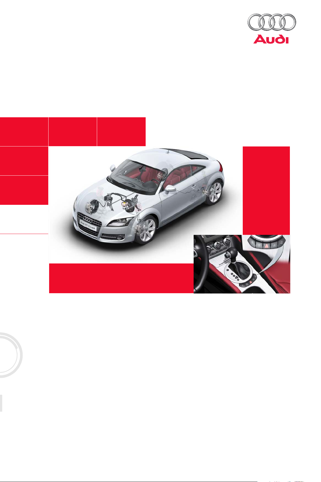
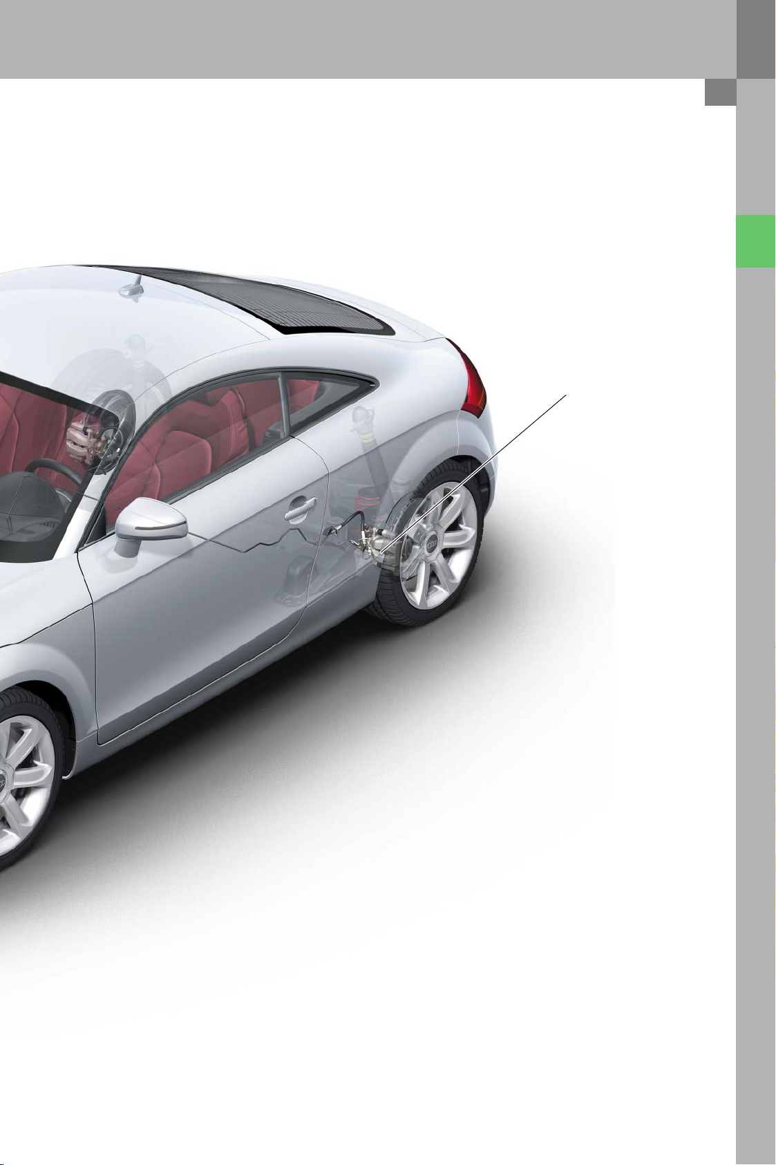
The new TT by Audi is a thoroughbred sports car.
The suspension system is one of the features key to
meeting this high standard. The basic TT has a conventional steel-sprung suspension - the so-called
"dynamic suspension system". The new Audi magnetic ride system is optional. It is a semi-active suspension system with magneto-rheologically
controlled dampers.
Sport or comfort damper settings can be selected at
the touch of a button.
The S-line suspension by quattro-GmbH has been
developed to meet the growing customer demand
for vehicle customisation. This suspension is sportier than the dynamic suspension and reduces vehicle ride height by 10 mm.
381_064
Page 3
Protected by copyright. Copying for private or commercial purposes, in part or in whole, is not
permitted unless authorised by AUDI AG. AUDI AG does not guarantee or accept any liability
with respect to the correctness of information in this document. Copyright by AUDI AG.
Contents
Axles
Front axle . . . . . . . . . . . . . . . . . . . . . . . . . . . . . . . . . . . . . . . . . . . . . . . . . . . . . . . . . . . . . . . . . . . . . . . . . 4
Rear axle . . . . . . . . . . . . . . . . . . . . . . . . . . . . . . . . . . . . . . . . . . . . . . . . . . . . . . . . . . . . . . . . . . . . . . . . . 9
Brake system
Overview . . . . . . . . . . . . . . . . . . . . . . . . . . . . . . . . . . . . . . . . . . . . . . . . . . . . . . . . . . . . . . . . . . . . . . . . 12
System components. . . . . . . . . . . . . . . . . . . . . . . . . . . . . . . . . . . . . . . . . . . . . . . . . . . . . . . . . . . . . . . 15
ESP
System components. . . . . . . . . . . . . . . . . . . . . . . . . . . . . . . . . . . . . . . . . . . . . . . . . . . . . . . . . . . . . . . 18
Operation and displays . . . . . . . . . . . . . . . . . . . . . . . . . . . . . . . . . . . . . . . . . . . . . . . . . . . . . . . . . . . . 20
Steering system
Electromechanical steering system EPS . . . . . . . . . . . . . . . . . . . . . . . . . . . . . . . . . . . . . . . . . . . . . .21
Steering column . . . . . . . . . . . . . . . . . . . . . . . . . . . . . . . . . . . . . . . . . . . . . . . . . . . . . . . . . . . . . . . . . . 22
Steering wheel . . . . . . . . . . . . . . . . . . . . . . . . . . . . . . . . . . . . . . . . . . . . . . . . . . . . . . . . . . . . . . . . . . . 22
Audi magnetic ride
Overview . . . . . . . . . . . . . . . . . . . . . . . . . . . . . . . . . . . . . . . . . . . . . . . . . . . . . . . . . . . . . . . . . . . . . . . . 23
Functional principle . . . . . . . . . . . . . . . . . . . . . . . . . . . . . . . . . . . . . . . . . . . . . . . . . . . . . . . . . . . . . . . 24
System components. . . . . . . . . . . . . . . . . . . . . . . . . . . . . . . . . . . . . . . . . . . . . . . . . . . . . . . . . . . . . . . 25
Special functions . . . . . . . . . . . . . . . . . . . . . . . . . . . . . . . . . . . . . . . . . . . . . . . . . . . . . . . . . . . . . . . . . 28
Function diagram . . . . . . . . . . . . . . . . . . . . . . . . . . . . . . . . . . . . . . . . . . . . . . . . . . . . . . . . . . . . . . . . . 30
CAN data exchange . . . . . . . . . . . . . . . . . . . . . . . . . . . . . . . . . . . . . . . . . . . . . . . . . . . . . . . . . . . . . . . 31
Scope of service . . . . . . . . . . . . . . . . . . . . . . . . . . . . . . . . . . . . . . . . . . . . . . . . . . . . . . . . . . . . . . . . . . 32
Wheels/tyres
Overview . . . . . . . . . . . . . . . . . . . . . . . . . . . . . . . . . . . . . . . . . . . . . . . . . . . . . . . . . . . . . . . . . . . . . . . . 34
Self Supporting Tires (SST) . . . . . . . . . . . . . . . . . . . . . . . . . . . . . . . . . . . . . . . . . . . . . . . . . . . . . . . . . 35
Low tyre pressure indicator 36
Tyre pressure monitoring system (US spec) . . . . . . . . . . . . . . . . . . . . . . . . . . . . . . . . . . . . . . . . . . . 44
The self-study programme teaches the design and function of new vehicle models,
new automotive components or new technologies.
The self-study programme is not a repair manual!
All values given are intended as a guideline only and refer to the software version valid at the time of preparation of the SSP.
For maintenance and repair work, always refer to the current technical literature.
NoteReference
Page 4
Protected by copyright. Copying for private or commercial purposes, in part or in whole, is not
permitted unless authorised by AUDI AG. AUDI AG does not guarantee or accept any liability
with respect to the correctness of information in this document. Copyright by AUDI AG.
Axles
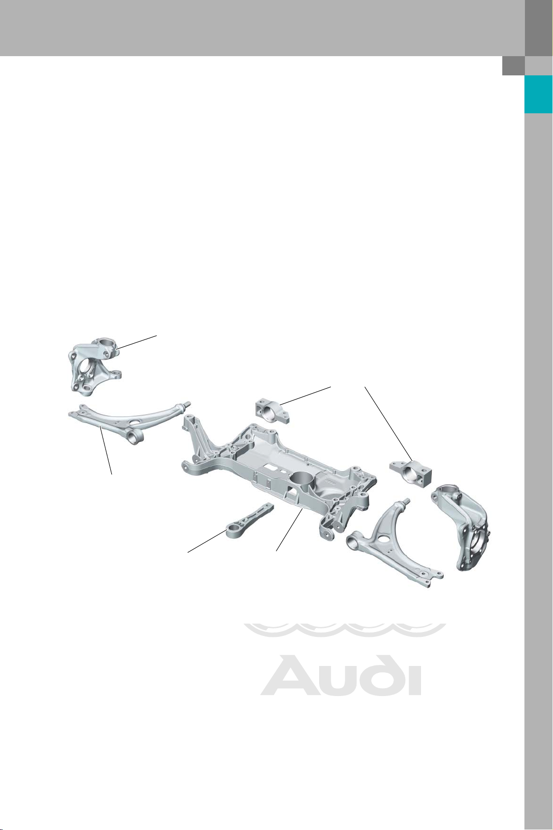
Front axle
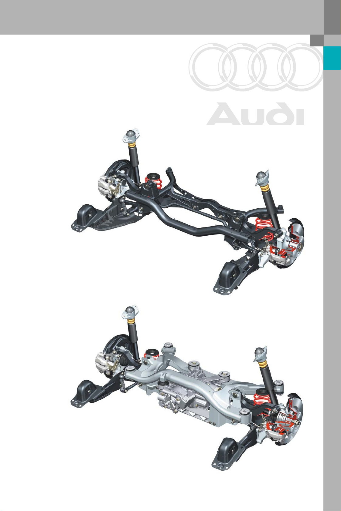
Overview
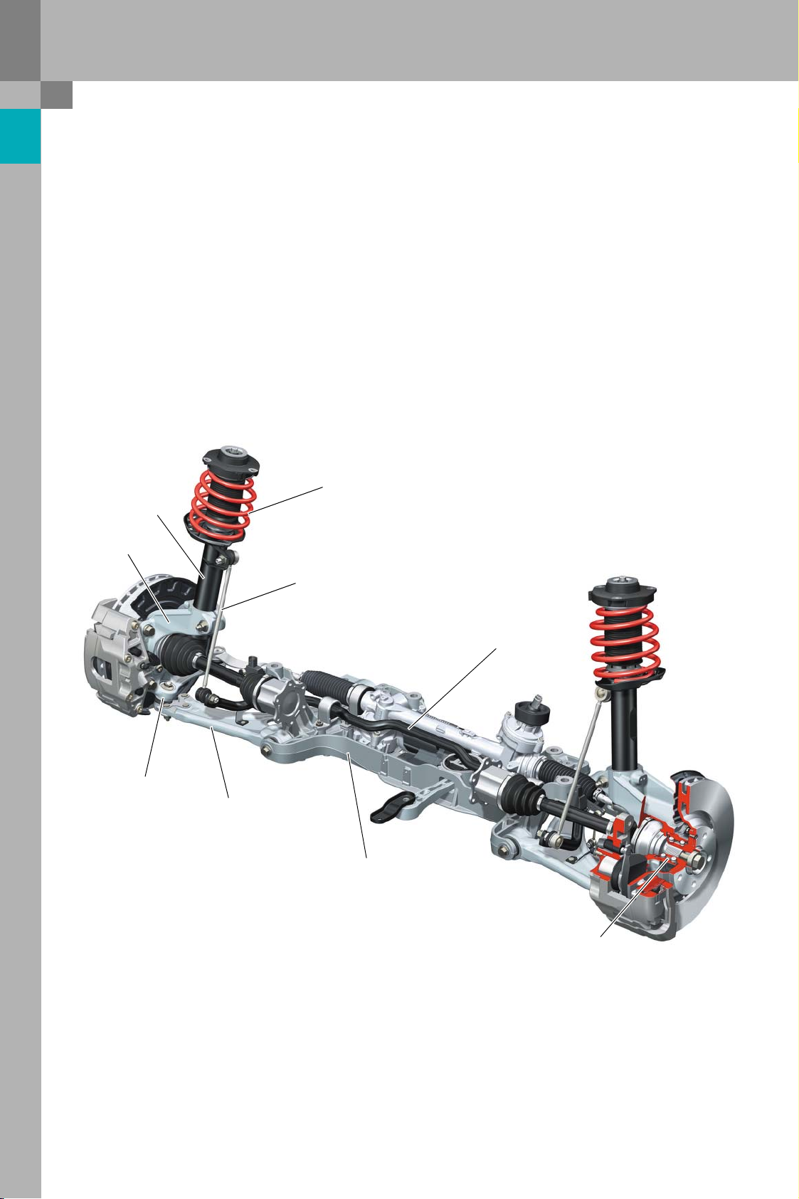
An improved version of the McPherson suspension
is employed. The design of the front axle is identical
to that of the Audi A3. Track width is 13 mm wider
on each side than the Audi A3.
Damper
Swivel bearing
Coupling rod
Detail modifications have been made to reflect the
particularly sporty character of the Audi TT. In addition to the tuning parts (springs, dampers and antiroll bars), the same axle components are used in all
TT suspension variants.
Spring
Ball joint
Anti-roll bar
Wishbone
Subframe
Wheel bearing
381_001
4
Page 5
Protected by copyright. Copying for private or commercial purposes, in part or in whole, is not
permitted unless authorised by AUDI AG. AUDI AG does not guarantee or accept any liability
with respect to the correctness of information in this document. Copyright by AUDI AG.
System components
Subframe
The aluminium subframe bears the wishbones, the
anti-roll bar and the steering gear of the electromechanical steering system. The two brackets for
mounting the wishbones are now common parts.
Swivel bearing
The Audi TT is living proof that sportiness and lightweight design go hand in hand. The illustration
shows the aluminium components of the front axle.
Brackets
Wishbone
Self-aligning support
Subframe
381_002
5
Page 6
Protected by copyright. Copying for private or commercial purposes, in part or in whole, is not
permitted unless authorised by AUDI AG. AUDI AG does not guarantee or accept any liability
with respect to the correctness of information in this document. Copyright by AUDI AG.
Axles
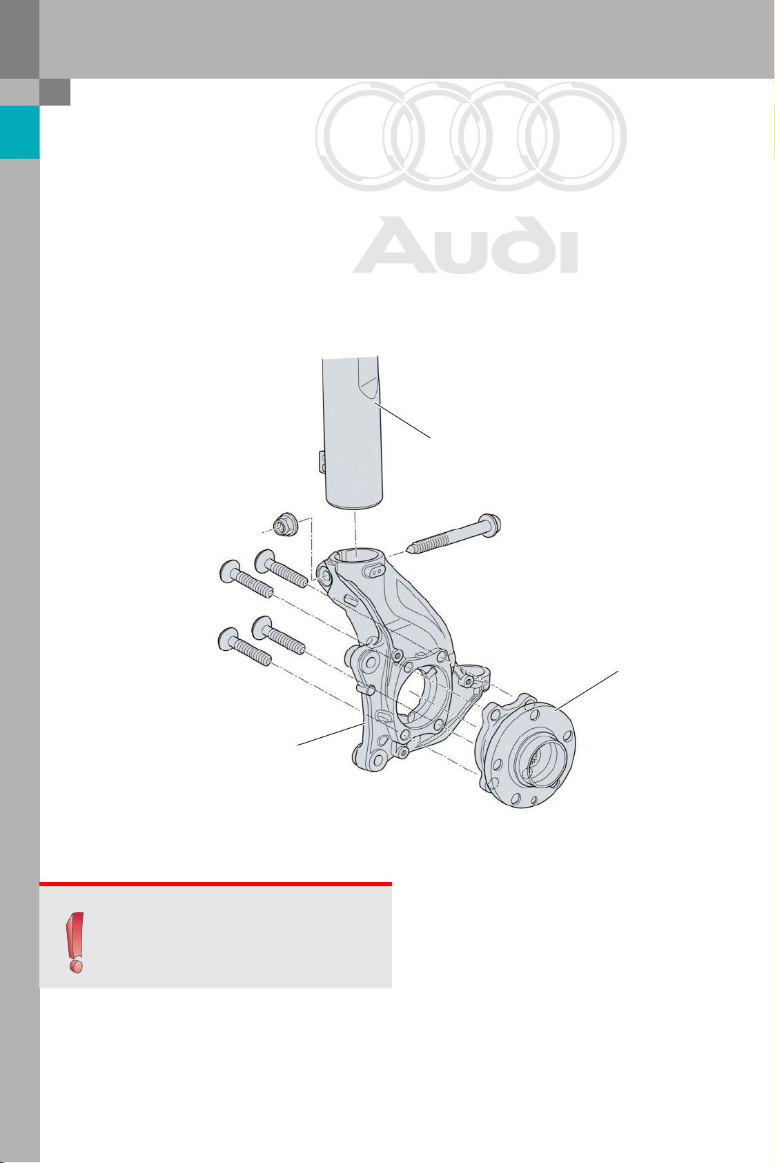
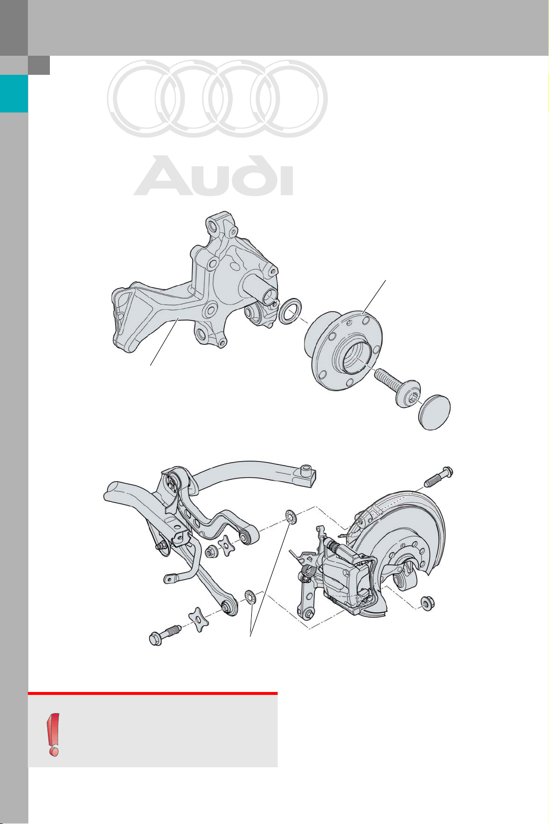
Swivel bearing, wheel bearing
The aluminium swivel bearing manufactured using
Cobapress technology* is a new part.Its geometric
design allows a wider track width to be achieved.
Steel bushes are press fitted into the swivel bearing
at the track rod and ball joint mounting points.
The third generation wheel bearing is bolted to the
swivel bearing.
The wheel bearings are carry-over parts from the
Audi A3. The screws are now coated with a chromium-6 free material to protect the environment.
The suspension strut is connected to the swivel
bearing by a clamp coupling.
Suspension strut
Swivel bearing
Note
Note: Special tool 3424 must always be used to
widen the clamp when installing and removing
the damper!
Wheel bearing
381_003
*: The Cobapress process is a casting process in which the component subsequently undergoes a forging
process. The result is high strength and toughness.
6
Page 7
Protected by copyright. Copying for private or commercial purposes, in part or in whole, is not
permitted unless authorised by AUDI AG. AUDI AG does not guarantee or accept any liability
with respect to the correctness of information in this document. Copyright by AUDI AG.
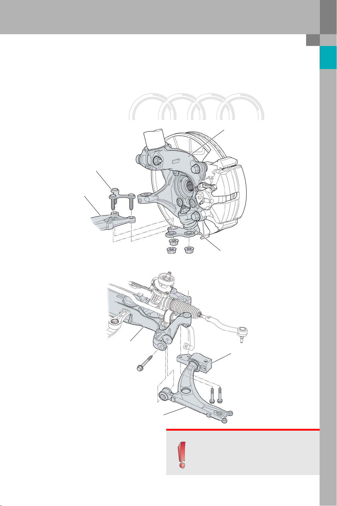
Wishbones, ball joint and bracket
The ball joint is connected to the wishbone at three
bolting points. Compared to the Audi A3, the fastening bolts are integral parts of a separate retaining
element. The bolts and retaining element are
inserted from above through the wishbone and ball
joint.
Retaining element
Wishbone
The wishbone is attached directly to the subframe at
the inside front and to the body at the inside rear by
means of an aluminium bracket.
Swivel bearing
Subframe
Wishbone
Ball joint
Bracket
381_004
381_005
Note
Note: after undoing the threaded connection
between the ball joint and wishbone, always
replace the retaining element.
7
Page 8
Protected by copyright. Copying for private or commercial purposes, in part or in whole, is not
permitted unless authorised by AUDI AG. AUDI AG does not guarantee or accept any liability
with respect to the correctness of information in this document. Copyright by AUDI AG.
Axles
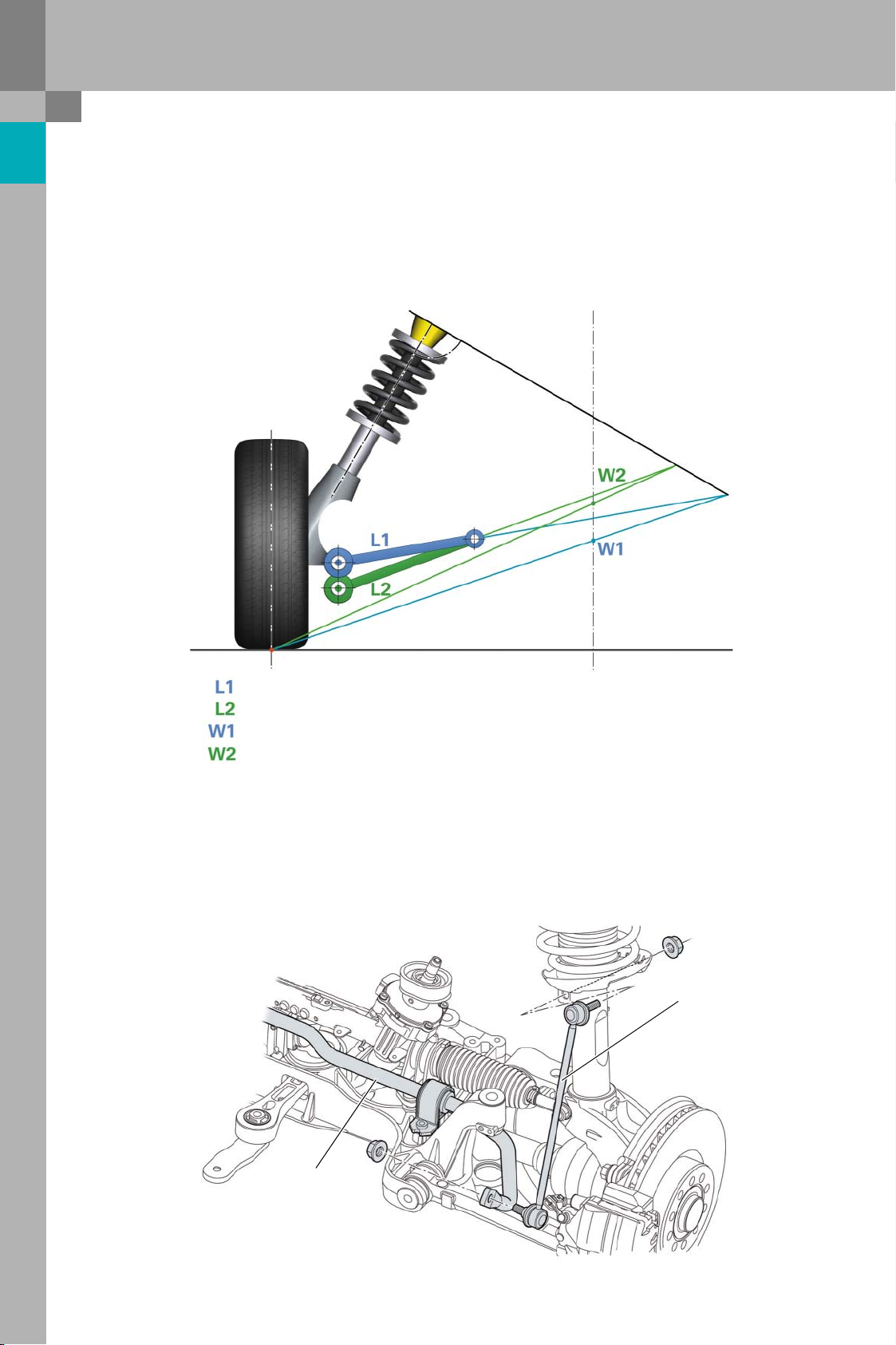
Wishbones, ball joint and bracket
The ball joint is in a lower position than on the Audi
A3. The result is a higher centre of roll. This
improves roll stabilisation and gives particularly
sporty handling.
The centre of roll is the level with the front axle in
the centre of the vehicle about which the body pivots when subjected to lateral forces, e.g. when cornering.
= position of the ball joint in the Audi A3
= lower position of the ball joint in the Audi TT
= position of the centre of roll in the Audi A3
= higher position of the centre of roll in the Audi TT
Anti-roll bar
A tubular anti-roll bar is used on models with frontwheel drive, while a solid bar is used on quattro
models.
The link rod is a carry-over part from the Audi A3.
381_006
Link rod
8
Anti-roll bar
381_007
Page 9
Protected by copyright. Copying for private or commercial purposes, in part or in whole, is not
permitted unless authorised by AUDI AG. AUDI AG does not guarantee or accept any liability
with respect to the correctness of information in this document. Copyright by AUDI AG.
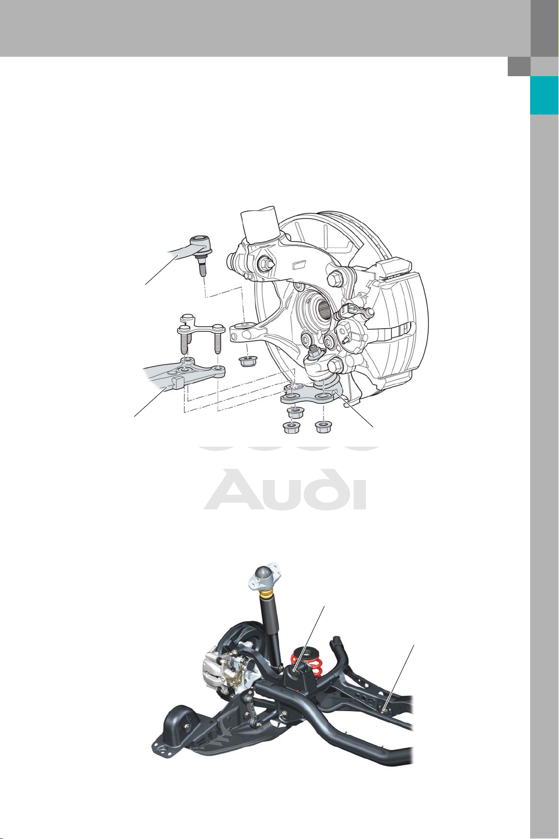
Rear axle
Overview
The rear axle of the Audi TT is basically identical in
design and function to the rear axle on the Audi A3 .
The wheel carriers, damper bearings and wheel
bearings are modified versions of the components
used in the Audi A3. Track width has been increased
by 15 mm on each side over the Audi A3.
Rear axle for front-wheel drive
The suspension and damping components (springs,
dampers and anti-roll bars) have been adapted to
the specific requirements of the Audi TT. Additional
stone chip protection is provided for certain markets. The trailing arms on these models are protected by plastic claddings.
Rear axle for quattro models
381_008
381_009
9
Page 10
Protected by copyright. Copying for private or commercial purposes, in part or in whole, is not
permitted unless authorised by AUDI AG. AUDI AG does not guarantee or accept any liability
with respect to the correctness of information in this document. Copyright by AUDI AG.
Axles
System components
Wheel carrier, wheel bearing
The wheel carrier has been modified geometrically
in order to increase track width. Front-wheel-drive
models use a second-generation wheel bearing
which is larger than the bearing on the Audi A3.The
diameter of the wheel carrier bearing journal has
been adapted to match the internal diameter of the
wheel bearing.
Wheel carrier
Ribbed washers are used for attaching the track
link, upper wishbones and damper to the wheel carrier.
These washers are required to achieve the necessary surface pressures.
Wheel bearing
381_010
Ribbed washers
381_011
Note
Note: Always replace the ribbed washers during
removal and installation of parts in the service
workshop.
10
Page 11
Protected by copyright. Copying for private or commercial purposes, in part or in whole, is not
permitted unless authorised by AUDI AG. AUDI AG does not guarantee or accept any liability
with respect to the correctness of information in this document. Copyright by AUDI AG.
Wheel alignment
Front axle
Toe and camber can be adjusted at the front axle.
The toe-out values are adjusted at the track rods.
Unlike on the Audi A3, left and right camber can be
adjusted separately.
Tra c k ro d
Wishbone
The camber is adjusted at the connection between
the wishbone and the guide bearing. For this purpose, the holes in the guide bearing are oblong in
shape.
Guide bearing
381_012
Rear axle
The camber and toe can be adjusted at the rear
axle.The adjustment procedure is the same as for
the Audi A3.
Camber adjustment
Toe adjustment
381_013
11
Page 12
Protected by copyright. Copying for private or commercial purposes, in part or in whole, is not
permitted unless authorised by AUDI AG. AUDI AG does not guarantee or accept any liability
with respect to the correctness of information in this document. Copyright by AUDI AG.
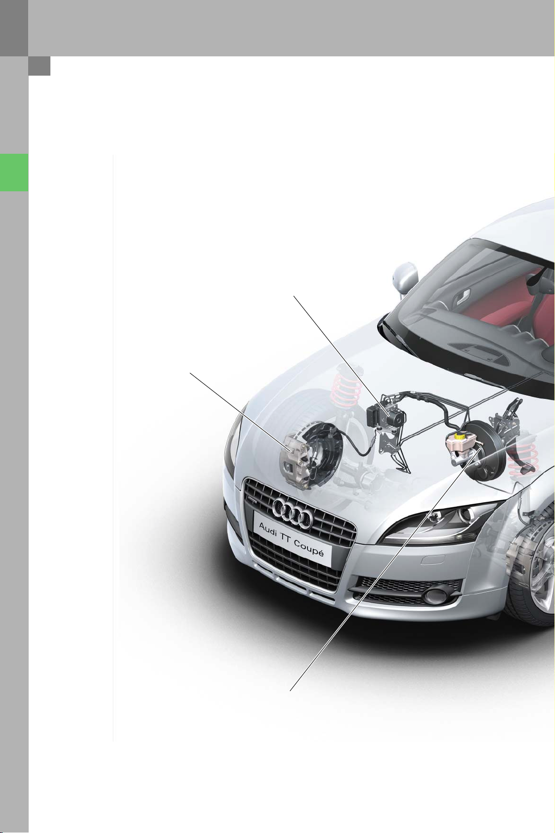
Brake system
Overview
optional Tyre Pressure Monitor
TEVES Mk60E1 with
Front axle brake caliper:
16" for all four-cylinder models
17" for all six-cylinder models
ESP:
10", 11", 7/8", with contactless brake
without dual rate characteristic
12
Brake servo:
light switch
Page 13
Protected by copyright. Copying for private or commercial purposes, in part or in whole, is not
permitted unless authorised by AUDI AG. AUDI AG does not guarantee or accept any liability
with respect to the correctness of information in this document. Copyright by AUDI AG.
Rear axle brake caliper:
16" for all four-cylinder models
17" for all six-cylinder models
381_014
13
Page 14
Protected by copyright. Copying for private or commercial purposes, in part or in whole, is not
permitted unless authorised by AUDI AG. AUDI AG does not guarantee or accept any liability
with respect to the correctness of information in this document. Copyright by AUDI AG.
Brake system
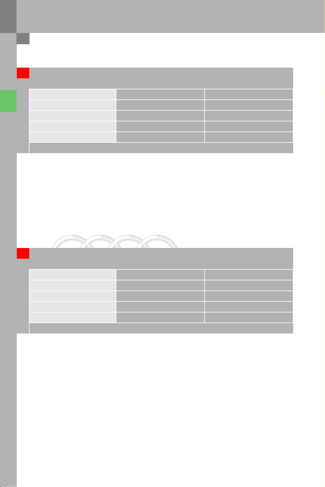
Front axle
Engine R4-4V 2.0l TFSI VR6 3.2l MPI
Minimum wheel size 16" 17"
Brake type FN3 FNR-G
Number of pistons 1 1
Piston diameter (mm) 54 57
Brake disc diameter (mm) 312 340
Rear axle
Engine R4-4V 2.0l TFSI VR6 3.2l MPI
Minimum wheel size 16" 17"
Brake type CII 38 CII 41
Number of pistons 1 1
Piston diameter (mm) 38 41
Brake disc diameter (mm) 286 310
14
Page 15
Protected by copyright. Copying for private or commercial purposes, in part or in whole, is not
permitted unless authorised by AUDI AG. AUDI AG does not guarantee or accept any liability
with respect to the correctness of information in this document. Copyright by AUDI AG.
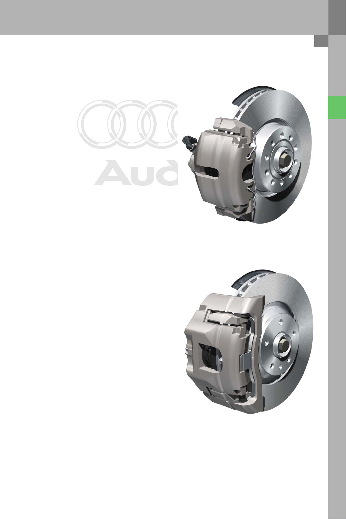
System components
Front axle wheel brake
The brake calipers are identical in design and
principle of operation to the brake calipers on the
Audi A3. A zinc-nickel coating is now applied. Brake
calipers are optionally available in a grey finish. The
brake discs for the 16" system have been adopted
from the Audi A3. The brake discs for the 17" system
are a modified version of the discs used on the Audi
A3. This change was necessary due to the modified
rim geometry of the SST wheels.
The Audi TT has new brake hoses with modified
holders on the swivel bearing compared to the Audi
A3.The 16" and 17" splash plates have been adopted
from the Audi A3. Break pad wear is measured in a
conventional fashion on the interior lining of the left
wheel brake. The 17" system is equipped with a
vibration damper. The damper is attached to the
brake caliper by the lower fastening bolt.
381_015
16" wheel brake
17" wheel brake
381_016
15
Page 16

Protected by copyright. Copying for private or commercial purposes, in part or in whole, is not
permitted unless authorised by AUDI AG. AUDI AG does not guarantee or accept any liability
with respect to the correctness of information in this document. Copyright by AUDI AG.
Brake system
Rear axle wheel brake
The brake calipers are identical in design and principle of operation to those on the Audi A3. The brake
carriers have been modified since the Audi TT has
wider rims than the Audi A3 and, because of this,
the requisite clearance for the handbrake cable
would not have been assured had the A3 brake carrier been adopted unchanged.
381_017
Compared to the Audi A3, the brake calipers have
been shifted 10 mm further inwards. Two new 16"
and 17" splash plates are used. The brake hoses
have been modified. In the Audi TT the transition
point from brake hose to brake line is located on the
side member (it is located on the subframe in the
Audi A3) .
16" wheel brake
381_018
17" wheel brake
16
Page 17

Protected by copyright. Copying for private or commercial purposes, in part or in whole, is not
permitted unless authorised by AUDI AG. AUDI AG does not guarantee or accept any liability
with respect to the correctness of information in this document. Copyright by AUDI AG.
Power brake unit / brake servo
In the case of the 16" systems, 10" single brake servos are used on left-hand-drive models and 7/8" tandem brake servos on right-hand drive models.
Vehicles with 17" systems are equipped with 11" single brake servos for left-hand-drive models and with
7/8" tandem brake servos for right-hand drive models.
For the Audi TT, no dual rate characteristic* was
applied to the brake servo.
The OHB-V function known from the Audi A3 * was
implemented on vehicles with 3.2l VR6 engine and
dual-clutch gearbox.
* dual rate and OHB-V are described in SSP 313
381_019
Like in Audi A3 models after November 2005, the
contactless brake light sensor is used on the Audi
TT. Brake light and brake test switches are no longer
required on the brake pedal.
The pedal assembly has been adopted from the
Audi A3.
Brake light sensor
381_020
17
Page 18

Protected by copyright. Copying for private or commercial purposes, in part or in whole, is not
permitted unless authorised by AUDI AG. AUDI AG does not guarantee or accept any liability
with respect to the correctness of information in this document. Copyright by AUDI AG.
ESP
System components
ESP unit
The Audi TT features a new ESP generation by Continental-Teves with the designation Mk60E1.
As with the Mk25E1 in the current Audi Q7, the
Mk60E1 has analogised switch valves
(4 intake valves and 2 block valves) and an integrated pressure sensor. In the case of analogised
switch valves, the port cross-section is determined
by the activation current. Unlike systems with conventional switch valves with the valve positions
open and closed, more precise brake control is possible.
Note
Due to the use of linearised switch valves, it is
no longer possible to disconnect the control
unit from the hydraulic unit in the service workshop.
In the ESP control unit has the same integrated
functions as in the Mk60 control unit on the Audi
A3, however these functions have been adapted to
the Audi TT. The hill hold assist (hha) and driver
steering recommendation (dsr) functions will be
implemented at a later date. The Audi A3 system
has been modified with regard to the operation of
the ESP Off key.
381_022
Block valve
Inlet valve
Linearised switch valves
ESP hydraulic unit
(excerpt showing the hydraulic
control device for a wheel brake)
381_023
18
Page 19

Protected by copyright. Copying for private or commercial purposes, in part or in whole, is not
permitted unless authorised by AUDI AG. AUDI AG does not guarantee or accept any liability
with respect to the correctness of information in this document. Copyright by AUDI AG.
Sensor unit G419
The sensor unit comprises senders G200 (lateral
acceleration sender), G202 (yaw rate sender) and, on
models with quattro four-wheel drive, G251 (longitudinal acceleration sender) . The sensor unit has
been adopted from the Audi A3. The service procedures for calibrating the sensors are the same as for
the Audi A3.
Wheel speed sensors G44 - G47
381_024
The wheel speed sensors for wheel speed measurement have been adopted from the Audi A3.
Steering angle sender G85
The steering angle sender is identical in design and
function to the sender on the Audi A3.
381_026
19
Page 20

Protected by copyright. Copying for private or commercial purposes, in part or in whole, is not
permitted unless authorised by AUDI AG. AUDI AG does not guarantee or accept any liability
with respect to the correctness of information in this document. Copyright by AUDI AG.
ESP
Operation and displays
The functions of button E256 for ESP and TCS were
extended as follows:
Briefly pressing the button (<3 s) deactivates only
the TCS function. TCS OFF improves traction when
starting from a stop on loose surfaces (e.g. on snow
or sand).
TCS OFF is active up to a road speed of 70 kph. TCS
is switched on automatically when this speed is
exceeded.In all-wheel-drive models, TCS is automatically switched off again when the vehicle's road
speed drops below 70 kph. In front-wheel-drive
models, TCS is not automatically switched off when
the vehicle's road speed drops below this threshold.
381_025
TCS OFF
381_027
If the button is pressed for longer than 3 s, the ESP
function is switched off.
When the brake is applied, TCS and ESP are
switched on again for the duration of the braking
manoeuvre and remain active until a stable driving
condition is restored.
The ESP function is activated automatically if faults
are diagnosed in the magnetic ride system or when
actuating the rear spoiler.
If the button is pressed for longer than 10 s, the ESP
function is switched on again and cannot be
switched off again until the ignition has been
turned off and on again.
ESP
SWITCHED
OFF
381_027a
ESP / TCS ON
381_027b
20
Page 21

Protected by copyright. Copying for private or commercial purposes, in part or in whole, is not
permitted unless authorised by AUDI AG. AUDI AG does not guarantee or accept any liability
with respect to the correctness of information in this document. Copyright by AUDI AG.
Electromechanical steering system EPS
The electromechanical steering system EPS which
has proved successful in the Audi A3 is also featured in the new Audi TT. The following modifications have been made compared to the Audi A3:
new track rod outer joint with
larger joint diameter and
modified journal geometry
Steering system
reduced steering angle, steering rack
shortened from 80 mm to 78 mm
new control unit due to new
control software without dsr fun ction
In the case of the Audi TT, the power steering assist maps
are determined by the powertrain type (front wheel drive
or quattro) In the case of the Audi A3, the weight of the
front axle is the determinant factor.
381_028
Reference
For detailed information on the design and
function of the EPS system, refer to SSP 313.
21
Page 22

Protected by copyright. Copying for private or commercial purposes, in part or in whole, is not
permitted unless authorised by AUDI AG. AUDI AG does not guarantee or accept any liability
with respect to the correctness of information in this document. Copyright by AUDI AG.
Steering system
Steering column
A mechanical steering column is used in the Audi
TT. The steering column is basically identical in
design and function to the steering column in the
Audi A3. The following modifications have been
made compared to the Audi A3:
Shear element for crash safety adapted to TT
Longer drive shaft
Steering wheel
A redesigned steering wheel is used in the Audi
TT.All models are fitted with three-spoke leatherbound steering wheels with integrated two-stage
airbag module. In addition to the standard version,
combinations are also available of multifunction,
Tiptronic and leather stitching in various colours.
The skeleton is made of magnesium. The diameter
of the steering wheel rim is 5 mm less than on the
Audi A3. As in the Audi A3, the airbag unit is bolted.
A new feature is the use cage nuts are used for tolerance compensation.The airbag module is centred
in the steering wheel with two locating pins.
Larger adjustment range:
Longitudinal adjustment: ± 30 mm
Height adjustment: ± 25 mm
381_029
381_030
22
Page 23

Protected by copyright. Copying for private or commercial purposes, in part or in whole, is not
permitted unless authorised by AUDI AG. AUDI AG does not guarantee or accept any liability
with respect to the correctness of information in this document. Copyright by AUDI AG.
Overview
The Audi TT is the first Audi to feature Audi magnetic ride - a new semi-active suspension system
with magneto-rheologically controlled dampers.
Sport or comfort damper settings can be selected at
the touch of a button.
Audi magnetic ride
Shock absorber damping
adjustment warning lamp K189
Shock absorber damping
adjustment valves N336-339
Shock absorber damping
adjustment button E387
ECD control unit (electronically
controlled damping) J250
Vehicle level senders
G76-78,G289
Audi magnetic ride improves driving dynamics and driving comfort for the following reasons:
– reduced body movement (pitch and roll)
– optimised vibration behaviour
– improved road-holding
– improved handling
381_031
23
Page 24

Protected by copyright. Copying for private or commercial purposes, in part or in whole, is not
permitted unless authorised by AUDI AG. AUDI AG does not guarantee or accept any liability
with respect to the correctness of information in this document. Copyright by AUDI AG.
Audi magnetic ride
Operating principle
The damping function is based on the magneto-rheological effect. The prerequisite for this is the use of
a special damping fluid. This magneto-rheological
fluid is a suspension consisting of a hydrocarbonbased synthetic oil in which soft magnetic particles
with a diameter of 3-10
µm are held in suspension.
Magneto-rheological fluid in
non-magnetised state
Magnetic particles Magnetic field
To stabilise the fluid, various additives are added.
Applying a magnetic field changes the properties of
the magneto-rheological fluid. The magnetic particles are aligned in the direction of the magnetic
field lines. This alters the flux voltage of the fluid.
Magneto-rheological fluid in
magnetised state
381_032
Piston bores
Magnetic coil not
activated
When the magnetic coils are not activated electrically, the magnetic particles are arranged irregularly
in the damper oil.During the piston stroke, the individual particles are forced with the fluid through the
piston bores. The particle-laden suspension damping fluid has a low resistance to the movement of
the piston. As a result the damping force is low.
Magnetic coil
activated
381_033
When the magnetic coil is activated electrically, the
magnetic particles are aligned with the magnetic
field lines. Thus, long particle chains form in the
vicinity of the piston.
These particle chains are aligned cross-wise before
the fluid enters the piston bores. During the piston
stroke, individual particles break up and are forced
with the fluid through the piston bores. To "break
up" these chains, force must be applied, i.e. work
must be done. The resistance which the piston must
overcome is greater than in the case of a non-energised magnetic coil, and is dependent on the
amount of electrical current and the strength of the
magnetic field.
This allows greater damping forces to be achieved.
24
Page 25

Protected by copyright. Copying for private or commercial purposes, in part or in whole, is not
permitted unless authorised by AUDI AG. AUDI AG does not guarantee or accept any liability
with respect to the correctness of information in this document. Copyright by AUDI AG.
System components
Damper
The magneto-rheological dampers are much simpler in design than conventional dampers. The complex conventional damping valves are no longer
required. These have been replaced by bores in the
piston through which the fluid is displaced. In addition, single-tube dampers are used. The magnetic
coils are integrated in the pistons.
Connector
Power is supplied through the hollow piston rods
along discrete lines from control unit J250. Depending on engine type (4 cylinder or 6 cylinder engines),
different front axle dampers are used.A single
damper is used for all engine types on the rear axle.
Bores
Pistons
Cable to electrical control
device
Connector
Front axle damper Rear axle damper
381_034
25
Page 26

Protected by copyright. Copying for private or commercial purposes, in part or in whole, is not
permitted unless authorised by AUDI AG. AUDI AG does not guarantee or accept any liability
with respect to the correctness of information in this document. Copyright by AUDI AG.
Audi magnetic ride
Damper
Variable activation of the solenoid valve allows the
shock absorber damping force to be adjusted over a
wide range.
Comparison of the damping force characteristics of Audi magnetic ride and conventional dampers
Tension (rebound)
0
Damper force [N]
Damping force adjustments are made within milliseconds. This allows the damping force to be adapted to
requirements during the bump and rebound cycles.
Sport setting
Comfort setting
Compression (bump)
Adjustment range of Audi magnetic ride
Conventional damper
Damping speed [m/s]
ECD control unit (electronically controlled damping) J250
The control unit receives the measured data from
the vehicle level sender, as well as information on
the current driving condition from the ESP. The control unit processes the data and thus determines
the momentary activation currents for the dampers.
Each damper is activated individually. The dampers
are not activated when the vehicle is stationary. The
control unit is located under the front passenger
seat.
Sport setting
381_035
381_036
26
Page 27

Protected by copyright. Copying for private or commercial purposes, in part or in whole, is not
permitted unless authorised by AUDI AG. AUDI AG does not guarantee or accept any liability
with respect to the correctness of information in this document. Copyright by AUDI AG.
Vehicle level senders G76-78, G289
The vehicle level senders are identical in design and
function to those used in the Audi A6 and Audi A8.
The sampling rate is 800 Hz. Design and function
are described in detail in SSP 343. Measured data is
read in by control unit J250 across discrete lines,
processed and relayed to the headlight range control, control unit via the CAN bus.
Shock absorber damping adjustment button E387
Warning lamp K189
The button is used to select a damper setting. In
standard operation the dampers are configured for
comfort. A sport damping characteristic can be activated pressing the button. The LED indicator integrated in the button indicates that the sport setting
is active. Depending on dash panel variant, an additional text message may appear.The signal from the
button is read in by the control unit across a discrete line.
381_037
Warning lamp
System faults are indicated by a warning lamp in
the dash panel insert.The warning lamp is checked
whenever the ignition is turned on.
The warning lamp also comes on if the dash panel
insert has been coded incorrectly.
381_038
381_039
27
Page 28

Protected by copyright. Copying for private or commercial purposes, in part or in whole, is not
permitted unless authorised by AUDI AG. AUDI AG does not guarantee or accept any liability
with respect to the correctness of information in this document. Copyright by AUDI AG.
Audi magnetic ride
Special functions
Temperature model
The suspension damping becomes softer with
increasing magneto-rheological fluid temperature.
A software module for temperature compensation
is integrated in the control unit. The rising temperature is compensated by increasing the magnetic coil
activation current.
Likewise, the activation current is reduced at low
ambient temperatures.
Temperature is determined indirectly by measuring
the resistance of the magnetic coil.
A current of 3A is applied to the coil for the duration
The required voltage is determined and the resistance is calculated.
The basic value is the resistance measured in a vehicle which has been shut off for at least 6 hours. The
following measurements are correlated with the
basic value. Based on the change in resistance, the
control unit determines the actual temperature in
the shock absorber damper.In addition, the temperature of the control unit is calculated. This is done
by evaluating the electrical currents provided by the
control unit to activate the coils.
of 40 ms.
Temperature shut-off
The magnetic coil activation current must be
increased in order to compensate for the effect of
temperature increase in the dampers. However,
increasing the electrical current causes further
heating of the magnetic coil.Upwards of a defined
threshold temperature of (90°C), therefore, it is no
longer possible for the driver to select 'Sport' mode.
In 'Sport' mode, higher damping forces are produced by increasing the magnetic coil activation
current. Activating the 'Sport' mode would, therefore, cause a further increase in the already high
temperature in the suspension damper. The control
unit is shut down when its temperature exceeds
110°C.
Emergency operation in case of failure in electrical activation of the magnetic coil
In case of failure in electrical activation of multiple
magnetic coils, the magnetic coils of all suspension
dampers are no longer activated.
Suspension damper force characteristic of Audi magnetic ride
Tension (rebound)
0
Damper force [N]
In this case, the most comfortable suspension
damping characteristic is set.
Compression (bump)
28
Damping speed [m/s]
Adjustment range of Audi magnetic ride
Most comfortable damper setting
381_040
Page 29

Protected by copyright. Copying for private or commercial purposes, in part or in whole, is not
permitted unless authorised by AUDI AG. AUDI AG does not guarantee or accept any liability
with respect to the correctness of information in this document. Copyright by AUDI AG.
Shock absorber test
When the button is pressed for longer than 5 s, the
magnetic coils are activated by the application of a
constant electrical current.In this state, the shock
absorbers can be tested on the test bench.
The indicator LED in the button flashes when the
"shock absorber test" mode is active. The system
exists the mode automatically when the button is
pressed again, after ignition on/off or when driving
at a speed of at least 10 kph.
381_041
29
Page 30

Protected by copyright. Copying for private or commercial purposes, in part or in whole, is not
permitted unless authorised by AUDI AG. AUDI AG does not guarantee or accept any liability
with respect to the correctness of information in this document. Copyright by AUDI AG.
Audi magnetic ride
Function diagram
Posi tive
Earth
Powertrain CAN bus
Input signal
Output signal
381_042
J250 ECD control unit (electronically controlled damping)
G76-78,G289 Vehicle level senders
N336-339 Damper adjustment valves
E387 Shock absorber damping adjustment button
30
Page 31

Protected by copyright. Copying for private or commercial purposes, in part or in whole, is not
permitted unless authorised by AUDI AG. AUDI AG does not guarantee or accept any liability
with respect to the correctness of information in this document. Copyright by AUDI AG.
CAN data exchange
J250 ECD control unit (electronically controlled
damping)
System status (2,5,8)
Activation of warning lamp, text display (8,5)
Position of button E387 (2,5,8)
Height front right, front left, rear right, rear left (4)
Automatic activation ESP (2,5,8)
J533 Diagnostic interface (8)
Date, time
Terminal 15 -counter
Mileage (km)
Time n ot in use
J519 Onboard power supply control unit (9)
Status of terminal 50
J220 Motronic control unit (1)
Momentary position of brake light switch, brake test
switch
Coolant temperature
Intake air temperature (ambient temperature)
Engine torque
Driver torque input
J104 ESP control unit (2)
ESP on or off
ESP system status
Momentary vehicle speed
ABS active
Lateral acceleration
Brake pressure
Yaw r a te
J527 Steering column electronics control unit (3)
G85 Wheel angle sender
Max. steering angle
Steering speed
Status of terminal 30
Information sent by control unit J250
Information received and evaluated
by control unit J250
J431 Headlight range control,
control unit (4)
(receiver only)
J285 Control unit with display in dash panel insert (5)
Time not in use of the vehicle
Status of combined light (terminal 58d)
Ambient temperature
VIN
381_043
Powertrain CAN bus
Dash panel insert CAN bus
Convenience CAN bus
31
Page 32

Protected by copyright. Copying for private or commercial purposes, in part or in whole, is not
permitted unless authorised by AUDI AG. AUDI AG does not guarantee or accept any liability
with respect to the correctness of information in this document. Copyright by AUDI AG.
Audi magnetic ride
Service work
Address
The system can be addressed in the diagnostic
tester under the address: 14 Wheel damping.
Coding
The coding tells the control unit the powertrain type
and engine type of the vehicle. The control unit
accepts the new coding after ignition on/off.
1 = heavy engine (6-cylinder)
3 = lightweight engine (4-cylinder)
3 = coupé with front-wheel drive
8 = coupé quattro
System initialisation - teaching in the new standard
position
The system initialisation must be performed when
the control unit J250 and/or one or more vehicle
level senders is replaced. The characteristic curves
of the vehicle level sender are stored in the control
unit
During the system initialisation procedure, the control unit is informed which vehicle ride heights at
the wheel positions match the actual measured values generated by the vehicle level sender. If these
assignments are known to the control unit, then all
measured values generated subsequently by the
vehicle level sender can be converted to vehicle ride
heights. The basic system initialisation procedure is
identical to the procedure for initialising the aas
systems in the A6 and A8. The system initialisation
can only be performed when the code control unit is
coded.
381_046
381_045
32
Page 33

Protected by copyright. Copying for private or commercial purposes, in part or in whole, is not
permitted unless authorised by AUDI AG. AUDI AG does not guarantee or accept any liability
with respect to the correctness of information in this document. Copyright by AUDI AG.
Final control diagnostics
The shock absorber dampers can be activated selectively in the final control diagnostics.
The shock absorber dampers are activated by applying a current of 2A.
Data blocks
The data blocks are used to check key system status
information.The temperature values calculated for
the dampers and control unit, for example, are represented in data block 28.
Cold starting
When control unit J250 or shock absorber dampers
are replaced, the control unit must determine the
electrical resistance values of the damper coils at
ambient temperature. The control unit saves these
values as "standard values" for purposes of temperature compensation (refer to "Special functions temperature model").
This function is activated automatically after ignition on, provided the vehicle has been out of use for
at least 3 hours (e.g. even after a a cold start in the
morning) . During this time not in use, the temperatures of the dampers have adjusted to the ambient
temperature. If the mechanic has fitted shock
absorber dampers which are already at ambient
temperature (e.g. parts sourced directly from the
spare parts warehouse), the resistance measurement function can be started immediately by activating the "Cold start" function with the diagnostic
tester.
Flashing
The control unit software can be flashed by an external data carrier (CD, online interface) .
33
Page 34

Protected by copyright. Copying for private or commercial purposes, in part or in whole, is not
permitted unless authorised by AUDI AG. AUDI AG does not guarantee or accept any liability
with respect to the correctness of information in this document. Copyright by AUDI AG.
Wheels and tyres
Overview
Engine Basic wheels Optional wheels Winter wheels
4-cylinder
6-cylinder
7.5J x 16 ET 45 (1)
Cast aluminium
wheel painted
225/55 R 16
8.5J x 17 ET 50 (2)
Forged aluminium
wheel painted
245/45 R 17
8J x 17 ET 47 (3)
Cast aluminium
wheel painted
225/50 R 17
9J x 18 ET 52 (4)
Cast aluminium
wheel painted
245/40 R 18
9J x 18 ET 52 (5)
Cast aluminium
wheel polished,
bicolor
225/50 R 17
9J x 18 ET 52 (6)
Cast aluminium
wheel painted
245/50 R 18
7J x 16 ET 47 (7)
Cast aluminium
wheel painted
225/50 R 17
7J x 17 ET 47 (8)
Forged aluminium
wheel painted
225/50 R 17
9J x 18 ET 52 (9)
Cast aluminium
wheel painted
245/40 R 18
also available optionally as SST wheel
381_047
34
Page 35

Protected by copyright. Copying for private or commercial purposes, in part or in whole, is not
permitted unless authorised by AUDI AG. AUDI AG does not guarantee or accept any liability
with respect to the correctness of information in this document. Copyright by AUDI AG.
Self Supporting Tires (SST)
SST tyres have run-flat capability because of their
modified design compared to conventional tyres.
Much stiffer tyre sidewalls enable the vehicle to
drive on for up to 50 km at a maximum speed of
80 kph even after a total loss of pressure.
Due to their modified tyre geometry, special wheels
with the designation EH2 (extended hump 2) are
used for SST tyres.To prevent inward displacement
of the tyre beads in case of loss of tyre pressure, the
bead seating has been modified substantially in
comparison with conventional wheels. The bead is
seated in a recess which supports the tyre towards
the inside of the rim.
The special 17" wheels on the Audi TT can be used
both for conventional tyres and for SST tyres. In the
case of the 18" wheels, conventional tyres are available in combination with conventional rims. SST
tyres are always combined with the low tyre pressure indicator.
381_048
Conventional wheel geometry
extended hump 2
Note
Tyres run in "limp home" mode must always be
replaced!
Special tools must be used to fit and remove
SST tyres.For detailed information, refer to the
"Workshop Equipment" catalogue
381_049
35
Page 36

Protected by copyright. Copying for private or commercial purposes, in part or in whole, is not
permitted unless authorised by AUDI AG. AUDI AG does not guarantee or accept any liability
with respect to the correctness of information in this document. Copyright by AUDI AG.
Wheels and tyres
Low tyre pressure indicator
Overview
In all markets except North America the Audi TT features a newly developed low tyre pressure indicator.
J285
J533
J793
Being an indirect measuring system, no tyre pressure sensors are installed in the wheels.
E492
J104
G44
G45
J285 Control unit with display in dash panel insert
J533 Data bus diagnostic interface
J793 Tyre pressure monitor control unit 2
E492 Tyre pressure monitor display button
J104 ESP control unit
36
G44-47 Wheel speed sensor
Dash panel insert CAN bus
Powe rtrain CA N bus
G46
G47
381_050
Page 37

Protected by copyright. Copying for private or commercial purposes, in part or in whole, is not
permitted unless authorised by AUDI AG. AUDI AG does not guarantee or accept any liability
with respect to the correctness of information in this document. Copyright by AUDI AG.
Design and function
Data processing in the Audi TT is performed by control unit J793, and is no longer an integral part of
the ESP control unit. The control unit is located
behind the dash panel insert.
Tyr e pre ssu re m on i tor di s play
control unit 2 J793
381_051
37
Page 38

Protected by copyright. Copying for private or commercial purposes, in part or in whole, is not
permitted unless authorised by AUDI AG. AUDI AG does not guarantee or accept any liability
with respect to the correctness of information in this document. Copyright by AUDI AG.
Wheels and tyres
Design and function
Using a new evaluation method, it is now possible
to detect simultaneous pressure loss to at multiple
wheels. Tyre pressures are monitored simultaneously using two different concepts.
1. Tyre circumference monitoring
– Tyre circumference decreases as a function of
loss of pressure. As a result the wheel must
rotate more quickly to cover the same distance as
a fully inflated tyre. Wheel speeds are transmitted to control unit J793 by the ESP control unit. In
the current Audi A3, the wheel speeds of the
diagonal wheels are added and both diagonal
sums are correlated with one another. In this
way, allowance is made for different wheel
speeds when cornering. In the Audi TT, the tyre
circumferences are compared axle by axle and
2. Tyre vibration monitoring
– Torsional vibration is excited in each tyre while
rolling, due to road surface unevenness. These
vibrations can be determined by evaluating the
wheel speed signals. When the tyre pressure
decreases, the vibration characteristics
change.This monitoring concept, which is an
additional feature compared to the Audi A3, it is
now possible to reliably detect simultaneous loss
of pressure at multiple wheels, as for example
occurs over time at all four wheels due to diffu-
sion.
side by side.
Allowance is made for yaw rate and steering
angle when cornering.
38
Page 39

Protected by copyright. Copying for private or commercial purposes, in part or in whole, is not
permitted unless authorised by AUDI AG. AUDI AG does not guarantee or accept any liability
with respect to the correctness of information in this document. Copyright by AUDI AG.
Operation and displays
Tyre pressure monitoring is activated with the SET
key. This function must always be activated when
tire pressures are changed or different wheels/tyres
are fitted to the vehicle. This can only be done when
the ignition is on and the vehicle stationary. The
SET key must be pressed for at least 5 seconds in
order to activate the tyre pressure monitoring
function.
381_061
Warnings are always indicated by the warning lamp
in the dash panel insert.
For this purpose, the warning lamp is activated in
two colours.
381_054
The following displays are possible:
– In the event of a rapid loss of pressure at a single
wheel (tyre damage), the red warning lamp is
activated. If the vehicle a driver information system, an additional text display appears indicating the position of the wheel affected.
– In case of slow loss of pressure, which occurs
gradually at multiple wheels due to diffusion, the
red warning lamp is also activated. In this case,
the optional text display appears but no positional information is given. The displays are activated when the tyre pressure drops below an a
coded minimum value.
– When system faults are detected, the yellow
warning lamp is activated.
39
Page 40

Protected by copyright. Copying for private or commercial purposes, in part or in whole, is not
permitted unless authorised by AUDI AG. AUDI AG does not guarantee or accept any liability
with respect to the correctness of information in this document. Copyright by AUDI AG.
Wheels and tyres
Operation and displays
The teach-in process is performed once after the
SET key is pressed for the low tyre pressure indicator. During the next trip, the control unit saves the
measured wheel speeds and the vibration characteristics of the wheels in various vehicle operating
states. The vehicle operating states are basically
defined by the following parameters: vehicle speed,
steering angle, transverse acceleration and yaw
velocity. These teach-in values subsequently make
up the target data which is used for monitoring.
After approximately 10 minutes of driving, it is
already possible to detect a breakdown (rapid loss
of pressure) . Approximately 60 minutes of driving
are required to detect diffusion loss (slow loss of
pressure).
381_061
Service work
Address
The system can be addressed in the
diagnostic tester under the address:
4C Tyre pressure monitor II.
Vehicle self-diagnostics
Select diagnostic
function
Display all diagnostic functions
02 - Query fault memory
05 - Clear fault memory
06 - End of output
07 - Encode control unit
Encoding the subbus system
08 - Read data block
16 - Access authorisation
Read out Challenge immobiliser IV
Activate immobiliser IV
Identification services
4C - Tyre pressure monitor II
8J0907274 8J0907274
J793 TPM+ H03 --- 0100
Coding 614100
Dealership number 98765
Goto Print
381_056
40
Page 41

Protected by copyright. Copying for private or commercial purposes, in part or in whole, is not
permitted unless authorised by AUDI AG. AUDI AG does not guarantee or accept any liability
with respect to the correctness of information in this document. Copyright by AUDI AG.
Coding
The coding tells the control unit the system variant,
powertrain type, gearbox type, wheel size and type
of tyre used on the vehicle. The control unit accepts
the new coding after ignition on/off.
Tyre type and size (16"-18", standard tyre, SST tyre)
Powertrain type (front, quattro, gearbox variant)
6 = PR No. 7K6 (= low tyre pressure indicator)
Data blocks
The data blocks are used to check key system status
information.
41
Page 42

Protected by copyright. Copying for private or commercial purposes, in part or in whole, is not
permitted unless authorised by AUDI AG. AUDI AG does not guarantee or accept any liability
with respect to the correctness of information in this document. Copyright by AUDI AG.
Wheels and tyres
Function diagram
381_057
Posi tive
Earth
Powertrain CAN bus
Input signal
Output signal
42
J793 Tyre pressure monitor control unit 2
J104 ESP control unit
E492 Tyre pressure monitor display button
A Signal from wheel speed sensor, rear right
B Signal from wheel speed sensor, rear left
C Signal from wheel speed sensor, front right
D Signal from wheel speed sensor, front left
Page 43

Protected by copyright. Copying for private or commercial purposes, in part or in whole, is not
permitted unless authorised by AUDI AG. AUDI AG does not guarantee or accept any liability
with respect to the correctness of information in this document. Copyright by AUDI AG.
CAN data exchange
J793 Tyre pressure monitor control unit 2
System status (all)
Activation of warning lamp, text display (7,6)
J533 Diagnostic interface (7)
Date, time
Ter mina l 15 - coun ter
Mileage (km)
Reversing light switch
Tra il e r d ete cte d
J285 Control unit with display in dash panel
insert (6)
Displayed vehicle speed
Handbrake activated
Error status, ambient temperature
J220 Motronic control unit (1)
CCS status
Clutch switch
Coolant temperature
Engine torque
Engine speed
Gearbox variant
J104 ESP control unit (2)
ESP system status
ABS active
EBD, EDL and ESP intervention
TCS and EBC requ est
TCS shift control
Brake light sensor
Lateral acceleration
Yaw rat e
J527 Steering column electronics control unit (3)
G85 Wheel angle sender
max. steering angle
J217 Automatic gearbox control unit (4)
Selector mechanism active
Target gear or selected gear
Selector lever position/driving program
Torque converter lock-up clutch
Information sent by control unit J793
Information received and evaluated by
control unit J793
J492 Four-wheel drive control unit (5)
Error status
Clutch open
Clutch torque
Clutch stiffness
381_058
Powe rtrain CA N bus
Dash panel insert CAN bus
43
Page 44

Protected by copyright. Copying for private or commercial purposes, in part or in whole, is not
permitted unless authorised by AUDI AG. AUDI AG does not guarantee or accept any liability
with respect to the correctness of information in this document. Copyright by AUDI AG.
Wheels and tyres
Tyre pressure monitoring system (US spec)
Overview
The Audi TT for the North American market uses an
improved version of the tyre pressure monitoring
system as featured previously in the Audi A6 (USA)
.It is a direct measuring system with tyre pressure
sensors in the wheels.
J285
J533
J502
E492
G222
J285 Control unit with display in dash panel insert
J533 Data bus diagnostic interface
J502 Tyre pressure monitor contro l uni t
E492 Tyre pressure monitor display button
G222-225 Tyre pressu re sensors
44
G223
G224 G225
381_059
Dash panel insert CAN
Powertra in CAN bus
Page 45

Protected by copyright. Copying for private or commercial purposes, in part or in whole, is not
permitted unless authorised by AUDI AG. AUDI AG does not guarantee or accept any liability
with respect to the correctness of information in this document. Copyright by AUDI AG.
Design and function
In the Audi TT the rear tyre pressure monitor aerial
R96 is integrated in the tyre pressure monitor control unit J502.The control unit is fitted in the low
tyre pressure indicator behind the dash panel
insert. In the case of the tyre pressure monitoring
system, communication with the vehicle periphery
via the convenience CAN bus.
Tyre pressure monitoring
The aerial receives the radio signals from tyre pressure sensors G222-G226. The sensors operate at a
radio frequency of 315MHz. The sensors are identical in design and function to those on the Audi A6.
A new feature is the use of the valve body as a
transmitter antenna. The valve body and sensor can
no longer be separated. As with the current models
A4, A6 and Q7, the sensors do not start to transmit
until the wheels being to turn. To meet the countryspecific statutory requirements, the battery service
life is 10 years. The tyre pressure of the spare wheel
is not monitored. When the customer orders a fullsize spare wheel, the sensor is already installed in
the wheel if the vehicle is equipped with a tyre pressure monitoring system.
Tra il er
system J502
381_051a
381_060
The E492 button used in the tyre pressure monitoring system is identical to the button used by the low
tyre pressure indicator. Pressing the button displays
the actual tyre pressures as new target pressures.
As with the low tyre pressure indicator, the button is
connected to the control unit by discrete lines.
381_061
45
Page 46

Protected by copyright. Copying for private or commercial purposes, in part or in whole, is not
permitted unless authorised by AUDI AG. AUDI AG does not guarantee or accept any liability
with respect to the correctness of information in this document. Copyright by AUDI AG.
Wheels and tyres
Design and function
Tyre pressure warnings are indicated by the yellow
warning lamp in the dash panel insert. No positionrelated warning is given. Warnings are indicated in
accordance with country-specific statutory requirements at a residual tyre pressure of 75% or less.Tyre
pressures are determined taking into account the
tyre air temperature.
381_054
46
Page 47

Protected by copyright. Copying for private or commercial purposes, in part or in whole, is not
permitted unless authorised by AUDI AG. AUDI AG does not guarantee or accept any liability
with respect to the correctness of information in this document. Copyright by AUDI AG.
Service work
The main changes to the service work on the low
tyre pressure indicator are listed in the following.
Coding
The coding tells the control unit the system variant,
powertrain type, gearbox type, wheel size and type
of tyre used on the vehicle. The control unit accepts
the new coding after ignition on/off.
Target pressure ,Y bar
Target pressure X, bar
Tyre (standard, limp-home, extra load)
8 = PR No. 7K8 (= tyre pressure monitoring system)
Adaption
The control unit learns the new tyre pressure sensors automatically when the ignition is turned on
after the vehicle has been shut off for at least 20
minutes. When new tyre pressure sensor identification numbers are recognised, the fault indicator
lamp is activated. The driver enable monitoring of
the actual tyre pressures by pressing the SET key.
The system is now ready for operation again.
The tyre pressure sensor identification numbers
can be transmitted manually to the control unit
using the function "10 Adaption". This bypasses the
waiting period. Each identification number is indicated on the tyre pressure sensor housing.
Note
The handheld transmitters for the tyre pressure
monitoring system VAS 6287 cannot be used on
the tyre pressure monitoring system of the
Audi TT.
47
Page 48

Protected by copyright. Copying for private or commercial purposes, in part or in whole, is not
permitted unless authorised by AUDI AG. AUDI AG does not guarantee or accept any liability
with respect to the correctness of information in this document. Copyright by AUDI AG.
Vorsprung durch Technik www.audi.de
381
All rights reserved.
Technical specifications
subject to change without
notice.
Copyright
AUDI AG
I/VK-35
Service.training@audi.de
Fax +49-841/89-36367
AUDI AG
D-85045 Ingolstadt
Technical status: 05/06
Printed in Germany
A06.5S00.26.20
 Loading...