

Page 1
Protected by copyright. Copying for private or commercial purposes, in part or in whole, is not
permitted unless authorised by AUDI AG. AUDI AG does not guarantee or accept any liability
with respect to the correctness of information in this document. Copyright by AUDI AG.
Service
Workshop Manual
Audi TT 2007 ➤
Running gear, front-wheel drive and four-wheel drive
Edition 08.2010
Service Department. Technical Information
Page 2

Protected by copyright. Copying for private or commercial purposes, in part or in whole, is not
permitted unless authorised by AUDI AG. AUDI AG does not guarantee or accept any liability
with respect to the correctness of information in this document. Copyright by AUDI AG.
Service
List of Workshop Manual Repair GroupsList of Workshop Manual
Repair GroupsList of Workshop Manual Repair Groups
Re pa ir G ro up
00 - Technical data
40 - Front suspension
42 - Rear suspension
44 - Wheels, tyres, vehicle geometry
48 - Steering
Technical information should always be available to the foremen and mechanics, because their
careful and constant adherence to the instructions is essential to ensure vehicle road-worthiness and
safety. In addition, the normal basic safety precautions for working on motor vehicles must, as a
matter of course, be observed.
All rights reserved.
No reproduction without prior agreement from publisher.
Copyright © 2010 Audi AG, Ingolstadt A005TT00120
Page 3

Protected by copyright. Copying for private or commercial purposes, in part or in whole, is not
permitted unless authorised by AUDI AG. AUDI AG does not guarantee or accept any liability
with respect to the correctness of information in this document. Copyright by AUDI AG.
Audi TT 2007 ➤
Running gear, front-wheel drive and four-wheel drive - Edition 08.2010
Contents
00 - Technical data . . . . . . . . . . . . . . . . . . . . . . . . . . . . . . . . . . . . . . . . . . . . . . . . . . . . 1
1 Technical data . . . . . . . . . . . . . . . . . . . . . . . . . . . . . . . . . . . . . . . . . . . . . . . . . . . . . . . . . . 1
1.1 Running gear . . . . . . . . . . . . . . . . . . . . . . . . . . . . . . . . . . . . . . . . . . . . . . . . . . . . . . . . . . . . 1
1.2 Steering . . . . . . . . . . . . . . . . . . . . . . . . . . . . . . . . . . . . . . . . . . . . . . . . . . . . . . . . . . . . . . . . 1
1.3 Wheels, tyres . . . . . . . . . . . . . . . . . . . . . . . . . . . . . . . . . . . . . . . . . . . . . . . . . . . . . . . . . . . . 1
2 Proper disposal of fluid-filled components . . . . . . . . . . . . . . . . . . . . . . . . . . . . . . . . . . . . . . 2
2.1 Releasing gas in gas-filled shock absorbers (front) . . . . . . . . . . . . . . . . . . . . . . . . . . . . . . 2
2.2 Releasing gas in gas-filled shock absorbers (rear) . . . . . . . . . . . . . . . . . . . . . . . . . . . . . . 3
2.3 Releasing gas in Audi magnetic ride shock absorbers (front) . . . . . . . . . . . . . . . . . . . . . . 3
2.4 Releasing gas in Audi magnetic ride shock absorbers (rear) . . . . . . . . . . . . . . . . . . . . . . . . 4
3 Checking shock absorbers . . . . . . . . . . . . . . . . . . . . . . . . . . . . . . . . . . . . . . . . . . . . . . . . . . 5
3.1 Leaks at shock absorbers . . . . . . . . . . . . . . . . . . . . . . . . . . . . . . . . . . . . . . . . . . . . . . . . . . 5
3.2 Checking shock absorbers when removed . . . . . . . . . . . . . . . . . . . . . . . . . . . . . . . . . . . . 5
3.3 Checking shock absorbers on shock tester . . . . . . . . . . . . . . . . . . . . . . . . . . . . . . . . . . . . 6
40 - Front suspension . . . . . . . . . . . . . . . . . . . . . . . . . . . . . . . . . . . . . . . . . . . . . . . . . . 9
1 General notes . . . . . . . . . . . . . . . . . . . . . . . . . . . . . . . . . . . . . . . . . . . . . . . . . . . . . . . . . . . . 9
1.1 General information . . . . . . . . . . . . . . . . . . . . . . . . . . . . . . . . . . . . . . . . . . . . . . . . . . . . . . 9
1.2 Contact corrosion . . . . . . . . . . . . . . . . . . . . . . . . . . . . . . . . . . . . . . . . . . . . . . . . . . . . . . . . 10
1.3 Repairing threads in longitudinal member . . . . . . . . . . . . . . . . . . . . . . . . . . . . . . . . . . . . . . 10
1.4 Lifting suspension to unladen position . . . . . . . . . . . . . . . . . . . . . . . . . . . . . . . . . . . . . . . . 11
1.5 Exploded views of front axle . . . . . . . . . . . . . . . . . . . . . . . . . . . . . . . . . . . . . . . . . . . . . . . . 13
2 Subframe, anti-roll bar, wishbone, swivel joint, vehicle level sender . . . . . . . . . . . . . . . . . . 14
2.1 Exploded view of subframe, anti-roll bar, wishbone, swivel joint, vehicle level sender . . . . 15
2.2 Removing and installing subframe . . . . . . . . . . . . . . . . . . . . . . . . . . . . . . . . . . . . . . . . . . . . 17
2.3 Servicing subframe . . . . . . . . . . . . . . . . . . . . . . . . . . . . . . . . . . . . . . . . . . . . . . . . . . . . . . . . 22
2.4 Locating subframe in position . . . . . . . . . . . . . . . . . . . . . . . . . . . . . . . . . . . . . . . . . . . . . . . . 25
2.5 Removing and installing anti-roll bar . . . . . . . . . . . . . . . . . . . . . . . . . . . . . . . . . . . . . . . . . . 26
2.6 Removing and installing wishbone and mounting bracket . . . . . . . . . . . . . . . . . . . . . . . . . . 27
2.7 Renewing bonded rubber bush in wishbone . . . . . . . . . . . . . . . . . . . . . . . . . . . . . . . . . . . . 31
2.8 Renewing mounting bracket for wishbone . . . . . . . . . . . . . . . . . . . . . . . . . . . . . . . . . . . . . . 34
2.9 Removing and installing swivel joint . . . . . . . . . . . . . . . . . . . . . . . . . . . . . . . . . . . . . . . . . . 35
2.10 Checking swivel joint . . . . . . . . . . . . . . . . . . . . . . . . . . . . . . . . . . . . . . . . . . . . . . . . . . . . . . 37
2.11 Removing and installing front left vehicle level sender G78 and front right vehicle level sender
G289 . . . . . . . . . . . . . . . . . . . . . . . . . . . . . . . . . . . . . . . . . . . . . . . . . . . . . . . . . . . . . . . . . . 37
3 Wheel bearing housing, wheel bearing unit . . . . . . . . . . . . . . . . . . . . . . . . . . . . . . . . . . . . 39
3.1 Exploded view of wheel bearing housing and wheel bearing unit . . . . . . . . . . . . . . . . . . . . 39
3.2 Removing and installing wheel bearing housing . . . . . . . . . . . . . . . . . . . . . . . . . . . . . . . . 40
3.3 Removing and installing wheel bearing unit . . . . . . . . . . . . . . . . . . . . . . . . . . . . . . . . . . . . 43
4 Audi magnetic ride (AMR) - electronic damping control . . . . . . . . . . . . . . . . . . . . . . . . . . . . 45
4.1 Overview of Audi magnetic ride (AMR) - electronic damping control . . . . . . . . . . . . . . . . . . 45
4.2 Removing and installing electronically controlled damping control unit J250 . . . . . . . . . . 46
4.3 Procedure for re-adapting reference position with vehicle diagnostic, testing and information
system VAS 5051B . . . . . . . . . . . . . . . . . . . . . . . . . . . . . . . . . . . . . . . . . . . . . . . . . . . . . . 46
5 Suspension strut . . . . . . . . . . . . . . . . . . . . . . . . . . . . . . . . . . . . . . . . . . . . . . . . . . . . . . . . . . 48
5.1 Exploded view of suspension strut . . . . . . . . . . . . . . . . . . . . . . . . . . . . . . . . . . . . . . . . . . . . 48
5.2 Removing and installing suspension strut . . . . . . . . . . . . . . . . . . . . . . . . . . . . . . . . . . . . . . 49
5.3 Servicing suspension strut . . . . . . . . . . . . . . . . . . . . . . . . . . . . . . . . . . . . . . . . . . . . . . . . . . 52
6 Drive shafts . . . . . . . . . . . . . . . . . . . . . . . . . . . . . . . . . . . . . . . . . . . . . . . . . . . . . . . . . . . . 55
6.1 General notes: . . . . . . . . . . . . . . . . . . . . . . . . . . . . . . . . . . . . . . . . . . . . . . . . . . . . . . . . . . 55
6.2 Loosening and tightening hexagon bolt securing drive shaft to wheel hub . . . . . . . . . . . . 56
6.3 Loosening and tightening twelve-point bolt securing drive shaft to wheel hub . . . . . . . . . . 56
Contents i
Page 4

Protected by copyright. Copying for private or commercial purposes, in part or in whole, is not
permitted unless authorised by AUDI AG. AUDI AG does not guarantee or accept any liability
with respect to the correctness of information in this document. Copyright by AUDI AG.
Audi TT 2007 ➤
Running gear, front-wheel drive and four-wheel drive - Edition 08.2010
6.4 Removing and installing drive shaft (version with bolted flange on inner joint) . . . . . . . . . . 58
6.5 Removing and installing drive shaft with sliding CV joint (version with splines on inner
joint) . . . . . . . . . . . . . . . . . . . . . . . . . . . . . . . . . . . . . . . . . . . . . . . . . . . . . . . . . . . . . . . . . . 60
6.6 Removing and installing drive shaft with triple roller joint AAR 3300i (with splines for stub
shaft on gearbox) . . . . . . . . . . . . . . . . . . . . . . . . . . . . . . . . . . . . . . . . . . . . . . . . . . . . . . . . 66
6.7 Removing and installing drive shaft with triple roller joint AAR 3300i (with splines for insertion
in gearbox) . . . . . . . . . . . . . . . . . . . . . . . . . . . . . . . . . . . . . . . . . . . . . . . . . . . . . . . . . . . . . . 70
6.8 Servicing drive shaft (sliding inner CV joint with 100 mm dia.) . . . . . . . . . . . . . . . . . . . . . . 74
6.9 Servicing drive shaft (sliding inner CV joint with 108 mm dia.) . . . . . . . . . . . . . . . . . . . . . . 82
6.10 Servicing drive shaft (sliding inner CV joint with splines, 100 mm dia.) . . . . . . . . . . . . . . . . 88
6.11 Checking outer constant velocity joint . . . . . . . . . . . . . . . . . . . . . . . . . . . . . . . . . . . . . . . . 93
6.12 Checking inner sliding CV joint . . . . . . . . . . . . . . . . . . . . . . . . . . . . . . . . . . . . . . . . . . . . . . 94
6.13 Servicing drive shaft with triple roller joint AAR 2600i . . . . . . . . . . . . . . . . . . . . . . . . . . . . 96
6.14 Dismantling and assembling drive shaft with triple roller joint AAR 2600i . . . . . . . . . . . . . . 100
6.15 Servicing drive shaft with triple roller joint AAR 3300i (with splines for insertion in gearbox)
. . . . . . . . . . . . . . . . . . . . . . . . . . . . . . . . . . . . . . . . . . . . . . . . . . . . . . . . . . . . . . . . . . . . . . . . 104
6.16 Servicing drive shaft with triple roller joint AAR 3300i (with splines for stub shaft on
gearbox) . . . . . . . . . . . . . . . . . . . . . . . . . . . . . . . . . . . . . . . . . . . . . . . . . . . . . . . . . . . . . . . . 109
42 - Rear suspension . . . . . . . . . . . . . . . . . . . . . . . . . . . . . . . . . . . . . . . . . . . . . . . . . . 116
1 General notes on rear axle . . . . . . . . . . . . . . . . . . . . . . . . . . . . . . . . . . . . . . . . . . . . . . . . . . 116
1.1 General notes: . . . . . . . . . . . . . . . . . . . . . . . . . . . . . . . . . . . . . . . . . . . . . . . . . . . . . . . . . . 116
1.2 Contact corrosion . . . . . . . . . . . . . . . . . . . . . . . . . . . . . . . . . . . . . . . . . . . . . . . . . . . . . . . . 117
1.3 Repairing damaged threads in longitudinal member (subframe to body) . . . . . . . . . . . . . . 117
1.4 Lifting suspension to unladen position . . . . . . . . . . . . . . . . . . . . . . . . . . . . . . . . . . . . . . . . 118
1.5 Overview of rear axle (front-wheel drive) . . . . . . . . . . . . . . . . . . . . . . . . . . . . . . . . . . . . . . 120
1.6 Overview of rear axle (four-wheel drive) . . . . . . . . . . . . . . . . . . . . . . . . . . . . . . . . . . . . . . 121
2 Subframe, diagonal strut, lower transverse link, upper transverse link, track rod, vehicle level
sender (front-wheel drive) . . . . . . . . . . . . . . . . . . . . . . . . . . . . . . . . . . . . . . . . . . . . . . . . . . 123
2.1 Exploded view of subframe, diagonal strut, lower transverse link, upper transverse link, track
rod, vehicle level sender (front-wheel drive) . . . . . . . . . . . . . . . . . . . . . . . . . . . . . . . . . . . . 123
2.2 Removing and installing subframe with attachments . . . . . . . . . . . . . . . . . . . . . . . . . . . . . . 125
2.3 Removing and installing diagonal struts . . . . . . . . . . . . . . . . . . . . . . . . . . . . . . . . . . . . . . . . 128
2.4 Removing and installing lower transverse link . . . . . . . . . . . . . . . . . . . . . . . . . . . . . . . . . . 129
2.5 Removing and installing upper transverse link . . . . . . . . . . . . . . . . . . . . . . . . . . . . . . . . . . 131
2.6 Removing and installing track rod . . . . . . . . . . . . . . . . . . . . . . . . . . . . . . . . . . . . . . . . . . . . 132
2.7 Removing and installing rear left vehicle level sender G76 and rear right vehicle level sender
G77 . . . . . . . . . . . . . . . . . . . . . . . . . . . . . . . . . . . . . . . . . . . . . . . . . . . . . . . . . . . . . . . . . . 134
3 Wheel bearing housing, wheel bearing unit, trailing arm with mounting bracket, stone
deflector . . . . . . . . . . . . . . . . . . . . . . . . . . . . . . . . . . . . . . . . . . . . . . . . . . . . . . . . . . . . . . . . 136
3.1 Exploded view of wheel bearing housing, wheel bearing unit, trailing arm with mounting
bracket, stone deflector . . . . . . . . . . . . . . . . . . . . . . . . . . . . . . . . . . . . . . . . . . . . . . . . . . . . 136
3.2 Removing and installing wheel bearing housing . . . . . . . . . . . . . . . . . . . . . . . . . . . . . . . . 137
3.3 Renewing bonded rubber bush for wheel bearing housing . . . . . . . . . . . . . . . . . . . . . . . . 142
3.4 Removing and installing wheel bearing unit . . . . . . . . . . . . . . . . . . . . . . . . . . . . . . . . . . . . 145
3.5 Removing and installing trailing arm with mounting bracket . . . . . . . . . . . . . . . . . . . . . . . . 147
3.6 Servicing trailing arm . . . . . . . . . . . . . . . . . . . . . . . . . . . . . . . . . . . . . . . . . . . . . . . . . . . . . . 151
3.7 Removing and installing stone deflector . . . . . . . . . . . . . . . . . . . . . . . . . . . . . . . . . . . . . . . . 153
4 Shock absorbers, coil springs . . . . . . . . . . . . . . . . . . . . . . . . . . . . . . . . . . . . . . . . . . . . . . 154
4.1 Exploded view of shock absorbers, coil springs . . . . . . . . . . . . . . . . . . . . . . . . . . . . . . . . . . 154
4.2 Removing and installing shock absorber . . . . . . . . . . . . . . . . . . . . . . . . . . . . . . . . . . . . . . 155
4.3 Servicing shock absorbers . . . . . . . . . . . . . . . . . . . . . . . . . . . . . . . . . . . . . . . . . . . . . . . . . . 156
4.4 Removing and installing coil spring . . . . . . . . . . . . . . . . . . . . . . . . . . . . . . . . . . . . . . . . . . 159
5 Anti-roll bar . . . . . . . . . . . . . . . . . . . . . . . . . . . . . . . . . . . . . . . . . . . . . . . . . . . . . . . . . . . . . . 161
5.1 Exploded view of anti-roll bar . . . . . . . . . . . . . . . . . . . . . . . . . . . . . . . . . . . . . . . . . . . . . . . . 161
5.2 Removing and installing anti-roll bar . . . . . . . . . . . . . . . . . . . . . . . . . . . . . . . . . . . . . . . . . . 161
ii Contents
Page 5

Protected by copyright. Copying for private or commercial purposes, in part or in whole, is not
permitted unless authorised by AUDI AG. AUDI AG does not guarantee or accept any liability
with respect to the correctness of information in this document. Copyright by AUDI AG.
Audi TT 2007 ➤
Running gear, front-wheel drive and four-wheel drive - Edition 08.2010
6 Subframe, lower transverse link, upper transverse link, track rod, vehicle level sender (four-
wheel drive) - Coupé . . . . . . . . . . . . . . . . . . . . . . . . . . . . . . . . . . . . . . . . . . . . . . . . . . . . . . 163
6.1 Exploded view of subframe, lower transverse link, upper transverse link, track rod, vehicle
level sender (four-wheel drive) - Coupé . . . . . . . . . . . . . . . . . . . . . . . . . . . . . . . . . . . . . . . . 163
6.2 Removing and installing subframe with attachments . . . . . . . . . . . . . . . . . . . . . . . . . . . . . . 165
6.3 Removing and installing subframe bushes . . . . . . . . . . . . . . . . . . . . . . . . . . . . . . . . . . . . . . 171
6.4 Removing and installing lower transverse link . . . . . . . . . . . . . . . . . . . . . . . . . . . . . . . . . . 174
6.5 Removing and installing upper transverse link . . . . . . . . . . . . . . . . . . . . . . . . . . . . . . . . . . 175
6.6 Removing and installing track rod . . . . . . . . . . . . . . . . . . . . . . . . . . . . . . . . . . . . . . . . . . . . 177
6.7 Removing and installing rear left vehicle level sender G76 and rear right vehicle level sender
G77 . . . . . . . . . . . . . . . . . . . . . . . . . . . . . . . . . . . . . . . . . . . . . . . . . . . . . . . . . . . . . . . . . . 179
7 Subframe, diagonal struts, cross member, lower transverse link, upper transverse link, track
rod, vehicle level sender (four-wheel drive) - Roadster . . . . . . . . . . . . . . . . . . . . . . . . . . . . 181
7.1 Exploded view of subframe, diagonal struts, cross member, lower transverse link, upper
transverse link, track rod, vehicle level sender (four-wheel drive) - Roadster . . . . . . . . . . 181
7.2 Removing and installing diagonal struts - Roadster . . . . . . . . . . . . . . . . . . . . . . . . . . . . . . 183
7.3 Removing and installing cross member - Roadster . . . . . . . . . . . . . . . . . . . . . . . . . . . . . . 184
8 Wheel bearing housing, wheel bearing unit, trailing arm with mounting bracket . . . . . . . . 185
8.1 Exploded view of wheel bearing housing, wheel bearing unit, trailing arm with mounting
bracket . . . . . . . . . . . . . . . . . . . . . . . . . . . . . . . . . . . . . . . . . . . . . . . . . . . . . . . . . . . . . . . . 185
8.2 Removing and installing wheel bearing housing . . . . . . . . . . . . . . . . . . . . . . . . . . . . . . . . 186
8.3 Renewing bonded rubber bush for wheel bearing housing . . . . . . . . . . . . . . . . . . . . . . . . 191
8.4 Removing and installing wheel bearing unit . . . . . . . . . . . . . . . . . . . . . . . . . . . . . . . . . . . . 193
8.5 Removing and installing trailing arm with mounting bracket . . . . . . . . . . . . . . . . . . . . . . . . 195
8.6 Servicing trailing arm . . . . . . . . . . . . . . . . . . . . . . . . . . . . . . . . . . . . . . . . . . . . . . . . . . . . . . 199
9 Shock absorbers, coil springs . . . . . . . . . . . . . . . . . . . . . . . . . . . . . . . . . . . . . . . . . . . . . . 202
9.1 Exploded view of shock absorbers, coil springs . . . . . . . . . . . . . . . . . . . . . . . . . . . . . . . . . . 202
9.2 Removing and installing shock absorber . . . . . . . . . . . . . . . . . . . . . . . . . . . . . . . . . . . . . . 203
9.3 Servicing shock absorbers . . . . . . . . . . . . . . . . . . . . . . . . . . . . . . . . . . . . . . . . . . . . . . . . . . 204
9.4 Removing and installing coil spring . . . . . . . . . . . . . . . . . . . . . . . . . . . . . . . . . . . . . . . . . . 207
10 Anti-roll bar . . . . . . . . . . . . . . . . . . . . . . . . . . . . . . . . . . . . . . . . . . . . . . . . . . . . . . . . . . . . . . 208
10.1 Exploded view of anti-roll bar . . . . . . . . . . . . . . . . . . . . . . . . . . . . . . . . . . . . . . . . . . . . . . . . 208
10.2 Removing and installing anti-roll bar . . . . . . . . . . . . . . . . . . . . . . . . . . . . . . . . . . . . . . . . . . 208
11 Drive shafts . . . . . . . . . . . . . . . . . . . . . . . . . . . . . . . . . . . . . . . . . . . . . . . . . . . . . . . . . . . . 210
11.1 General notes: . . . . . . . . . . . . . . . . . . . . . . . . . . . . . . . . . . . . . . . . . . . . . . . . . . . . . . . . . . 210
11.2 Loosening and tightening hexagon bolt securing drive shaft to wheel hub . . . . . . . . . . . . 210
11.3 Loosening and tightening twelve-point bolt securing drive shaft to wheel hub . . . . . . . . . . 211
11.4 Removing and installing drive shaft . . . . . . . . . . . . . . . . . . . . . . . . . . . . . . . . . . . . . . . . . . 213
11.5 Servicing drive shaft with outer constant velocity joint, 90 mm diameter . . . . . . . . . . . . . . 214
11.6 Servicing drive shaft with outer constant velocity joint, 82 mm diameter . . . . . . . . . . . . . . 222
11.7 Checking outer constant velocity joint . . . . . . . . . . . . . . . . . . . . . . . . . . . . . . . . . . . . . . . . 228
11.8 Checking inner constant velocity joint . . . . . . . . . . . . . . . . . . . . . . . . . . . . . . . . . . . . . . . . 229
44 - Wheels, tyres, vehicle geometry . . . . . . . . . . . . . . . . . . . . . . . . . . . . . . . . . . . . . . 232
1 Wheels, tyres . . . . . . . . . . . . . . . . . . . . . . . . . . . . . . . . . . . . . . . . . . . . . . . . . . . . . . . . . . . . 232
2 Tyre monitor display (TMD+) . . . . . . . . . . . . . . . . . . . . . . . . . . . . . . . . . . . . . . . . . . . . . . . . 233
2.1 General notes: . . . . . . . . . . . . . . . . . . . . . . . . . . . . . . . . . . . . . . . . . . . . . . . . . . . . . . . . . . 233
2.2 Removing and installing tyre pressure monitoring control unit 2 J793 . . . . . . . . . . . . . . . . 233
3 Tyre pressure monitoring system (TPM) . . . . . . . . . . . . . . . . . . . . . . . . . . . . . . . . . . . . . . 235
3.1 General notes . . . . . . . . . . . . . . . . . . . . . . . . . . . . . . . . . . . . . . . . . . . . . . . . . . . . . . . . . . . . 235
3.2 Tyre pressure monitoring system - exploded view of components . . . . . . . . . . . . . . . . . . 236
3.3 Operation of tyre pressure monitoring system . . . . . . . . . . . . . . . . . . . . . . . . . . . . . . . . . . 236
3.4 Removing and installing tyre pressure monitor control unit J502 . . . . . . . . . . . . . . . . . . . . 238
3.5 Exploded view of tyre pressure sensor . . . . . . . . . . . . . . . . . . . . . . . . . . . . . . . . . . . . . . . . 239
3.6 Removing and installing tyre pressure sensor . . . . . . . . . . . . . . . . . . . . . . . . . . . . . . . . . . 239
3.7 Changing a tyre . . . . . . . . . . . . . . . . . . . . . . . . . . . . . . . . . . . . . . . . . . . . . . . . . . . . . . . . . . 240
Contents iii
Page 6

Protected by copyright. Copying for private or commercial purposes, in part or in whole, is not
permitted unless authorised by AUDI AG. AUDI AG does not guarantee or accept any liability
with respect to the correctness of information in this document. Copyright by AUDI AG.
Audi TT 2007 ➤
Running gear, front-wheel drive and four-wheel drive - Edition 08.2010
4 Wheel alignment . . . . . . . . . . . . . . . . . . . . . . . . . . . . . . . . . . . . . . . . . . . . . . . . . . . . . . . . . . 242
4.1 General information . . . . . . . . . . . . . . . . . . . . . . . . . . . . . . . . . . . . . . . . . . . . . . . . . . . . . . 242
4.2 Wheel alignment must be checked: . . . . . . . . . . . . . . . . . . . . . . . . . . . . . . . . . . . . . . . . . . 243
4.3 Explanatory notes on weight codes used in production (PR numbers) . . . . . . . . . . . . . . . . 244
4.4 Test requirements: . . . . . . . . . . . . . . . . . . . . . . . . . . . . . . . . . . . . . . . . . . . . . . . . . . . . . . . . 245
4.5 Wheel alignment specifications, front-wheel drive and four-wheel drive (Coupé/Roadster)
. . . . . . . . . . . . . . . . . . . . . . . . . . . . . . . . . . . . . . . . . . . . . . . . . . . . . . . . . . . . . . . . . . . . . . . . 246
4.6 Measurement procedure . . . . . . . . . . . . . . . . . . . . . . . . . . . . . . . . . . . . . . . . . . . . . . . . . . 247
4.7 Adjusting camber at front wheels . . . . . . . . . . . . . . . . . . . . . . . . . . . . . . . . . . . . . . . . . . . . 248
4.8 Adjusting camber at rear wheels . . . . . . . . . . . . . . . . . . . . . . . . . . . . . . . . . . . . . . . . . . . . 249
4.9 Adjusting toe setting at rear wheels . . . . . . . . . . . . . . . . . . . . . . . . . . . . . . . . . . . . . . . . . . 250
4.10 Adjusting toe setting at front wheels . . . . . . . . . . . . . . . . . . . . . . . . . . . . . . . . . . . . . . . . . . 250
48 - Steering . . . . . . . . . . . . . . . . . . . . . . . . . . . . . . . . . . . . . . . . . . . . . . . . . . . . . . . . 251
1 General repair instructions . . . . . . . . . . . . . . . . . . . . . . . . . . . . . . . . . . . . . . . . . . . . . . . . . . 251
1.1 Steering box . . . . . . . . . . . . . . . . . . . . . . . . . . . . . . . . . . . . . . . . . . . . . . . . . . . . . . . . . . . . 251
1.2 Gaskets and seals . . . . . . . . . . . . . . . . . . . . . . . . . . . . . . . . . . . . . . . . . . . . . . . . . . . . . . . . 251
1.3 Bolts and nuts . . . . . . . . . . . . . . . . . . . . . . . . . . . . . . . . . . . . . . . . . . . . . . . . . . . . . . . . . . . . 252
1.4 Electrical components . . . . . . . . . . . . . . . . . . . . . . . . . . . . . . . . . . . . . . . . . . . . . . . . . . . . 252
1.5 Guided Fault Finding, Vehicle Self-Diagnosis and Test Instruments . . . . . . . . . . . . . . . . . . 252
2 Steering wheel with airbag . . . . . . . . . . . . . . . . . . . . . . . . . . . . . . . . . . . . . . . . . . . . . . . . . . 253
2.1 Steering wheel with airbag - exploded view . . . . . . . . . . . . . . . . . . . . . . . . . . . . . . . . . . . . 253
2.2 Removing and installing steering wheel with airbag . . . . . . . . . . . . . . . . . . . . . . . . . . . . . . 253
3 Steering column, mounting bracket with strut . . . . . . . . . . . . . . . . . . . . . . . . . . . . . . . . . . 255
3.1 Steering column and mounting bracket with strut (LHD vehicles) - exploded view . . . . . . 255
3.2 Removing and installing steering column . . . . . . . . . . . . . . . . . . . . . . . . . . . . . . . . . . . . . . 256
3.3 Handling and transporting steering column . . . . . . . . . . . . . . . . . . . . . . . . . . . . . . . . . . . . 259
3.4 Checking steering column for damage . . . . . . . . . . . . . . . . . . . . . . . . . . . . . . . . . . . . . . . . 261
3.5 Removing and installing mounting bracket with strut . . . . . . . . . . . . . . . . . . . . . . . . . . . . . . 261
3.6 Steering column and mounting bracket with strut (RHD vehicles) - exploded view . . . . . . 262
4 Electro-mechanical steering box . . . . . . . . . . . . . . . . . . . . . . . . . . . . . . . . . . . . . . . . . . . . 264
4.1 Differences between steering boxes (generations 2 and 3) . . . . . . . . . . . . . . . . . . . . . . . . 264
4.2 Electro-mechanical steering box (LHD vehicles) - exploded view . . . . . . . . . . . . . . . . . . . . 266
4.3 Removing and installing electro-mechanical steering box . . . . . . . . . . . . . . . . . . . . . . . . . . 267
4.4 Exploded view - servicing electro-mechanical steering box . . . . . . . . . . . . . . . . . . . . . . . . 272
4.5 Removing and installing rubber boot . . . . . . . . . . . . . . . . . . . . . . . . . . . . . . . . . . . . . . . . . . 275
4.6 Removing and installing track rod . . . . . . . . . . . . . . . . . . . . . . . . . . . . . . . . . . . . . . . . . . . . 278
4.7 Removing and installing bonded rubber bush for generation 2 steering box . . . . . . . . . . . . 281
4.8 Renewing sensor wiring . . . . . . . . . . . . . . . . . . . . . . . . . . . . . . . . . . . . . . . . . . . . . . . . . . . . 281
4.9 Renewing and adjusting hydraulic thrust piece . . . . . . . . . . . . . . . . . . . . . . . . . . . . . . . . . . 285
4.10 Renewing and adjusting thrust piece at steering pinion end . . . . . . . . . . . . . . . . . . . . . . . . 291
4.11 Removing and installing steering pinion with steering moment sender G269 . . . . . . . . . . 298
4.12 Electro-mechanical steering box (RHD vehicles) - exploded view . . . . . . . . . . . . . . . . . . . . 302
iv Contents
Page 7
Protected by copyright. Copying for private or commercial purposes, in part or in whole, is not
permitted unless authorised by AUDI AG. AUDI AG does not guarantee or accept any liability
with respect to the correctness of information in this document. Copyright by AUDI AG.
Running gear, front-wheel drive and four-wheel drive - Edition 08.2010
00 – Technical data
1 Technical data
⇒ „1.1 Running gear“, page 1
⇒ „1.2 Steering“, page 1
⇒ „1.3 Wheels, tyres“, page 1
1.1 Running gear
Audi TT 2007 ➤
Front axle
Rear axle
Wheelbase mm 2467
Track width (front/rear)
1) Front/rear track width only applicable to tyre size 225/55/R16 on 7.5Jx16 ET45
rims (ET= rim offset)
1)
mm 1572 / 1558
Four-link suspension with separate spring/shock absorber layout
Front-wheel drive and four-wheel drive
MacPherson struts with bottom wishbones
Subframe
Anti-roll bar
Tubular anti-roll bar
1.2 Steering
Steering
box
Maximum steering angle at in‐
side wheel
Turning circle diameter approx. 10.9 m
Electro-mechanically assisted, maintenance-free rack-and-pinion steering
Front-wheel drive and four-wheel drive
36° 48'
1.3 Wheels, tyres
For general information on wheel/tyre combinations, winter tyres,
snow chains and recommended tyre makes, refer to ⇒ Wheel/
Tyre Guide .
1. Technical data 1
Page 8
Protected by copyright. Copying for private or commercial purposes, in part or in whole, is not
permitted unless authorised by AUDI AG. AUDI AG does not guarantee or accept any liability
with respect to the correctness of information in this document. Copyright by AUDI AG.
Audi TT 2007 ➤
Running gear, front-wheel drive and four-wheel drive - Edition 08.2010
2 Proper disposal of fluid-filled compo‐
nents
⇒ „2.1 Releasing gas in gas-filled shock absorbers (front)“,
page 2
⇒ „2.2 Releasing gas in gas-filled shock absorbers (rear)“,
page 3
⇒ „2.3 Releasing gas in Audi magnetic ride shock absorbers
(front)“, page 3
⇒ „2.4 Releasing gas in Audi magnetic ride shock absorbers
(rear)“, page 4
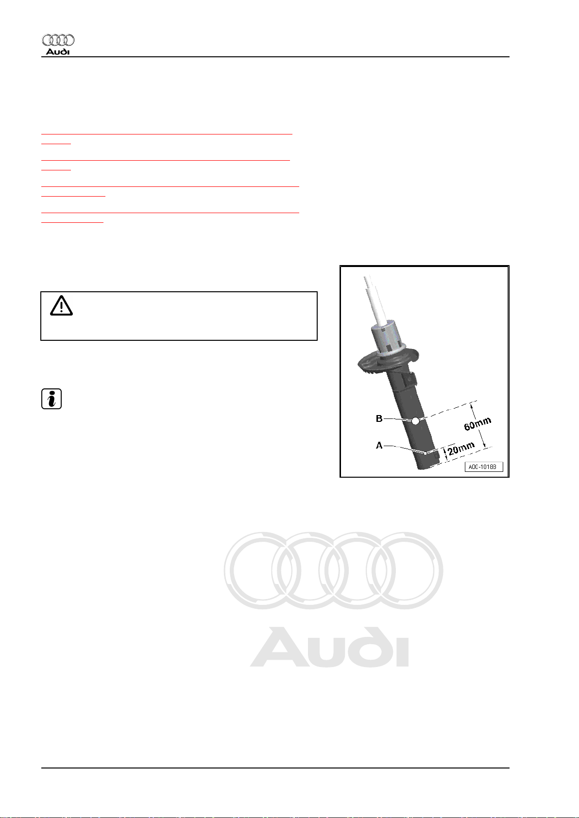
2.1 Releasing gas in gas-filled shock ab‐
sorbers (front)
– Clamp gas-filled shock absorber vertically in vice, with piston
rod pointing downwards.
WARNING
Safety goggles must be worn when drilling.
– Drill a 3 mm ∅ hole -arrow A- through outer tube of shock ab‐
sorber.
Note
Gas will escape during drilling.
– Continue drilling until inner tube is fully penetrated (approx.
25 mm deep).
– Drill a second 6 mm ∅ hole -arrow B- through outer and inner
tubes of shock absorber.
– Hold shock absorber over a drip tray and move piston rod up
and down several times through entire stroke until no more
fluid comes out.
2 Rep. gr.00 - Technical data
Page 9
Protected by copyright. Copying for private or commercial purposes, in part or in whole, is not
permitted unless authorised by AUDI AG. AUDI AG does not guarantee or accept any liability
with respect to the correctness of information in this document. Copyright by AUDI AG.
Running gear, front-wheel drive and four-wheel drive - Edition 08.2010
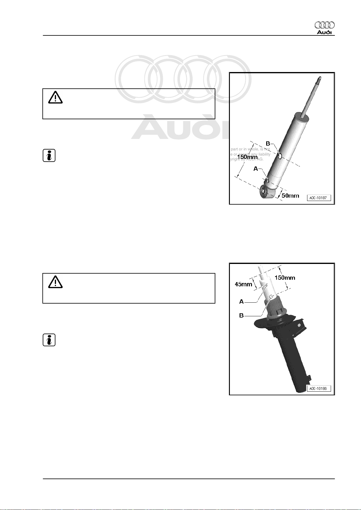
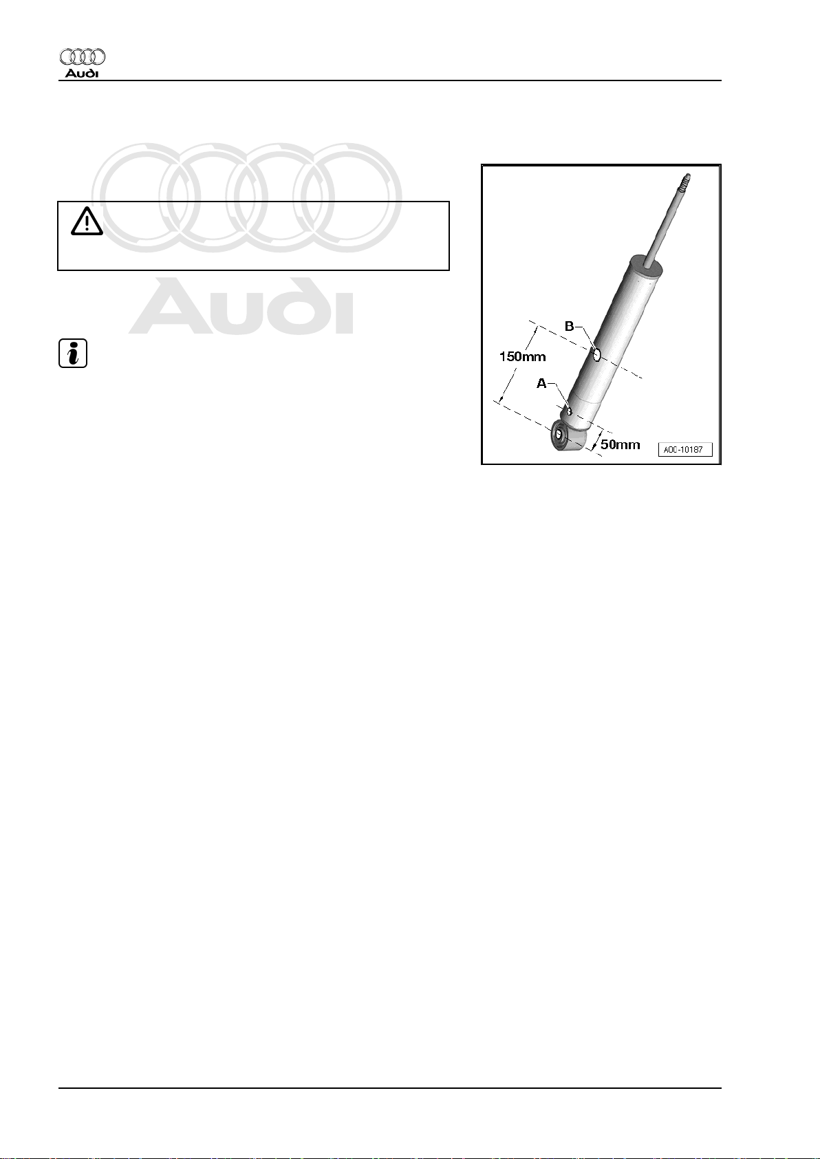
2.2 Releasing gas in gas-filled shock ab‐
sorbers (rear)
– Clamp gas-filled shock absorber vertically in vice, with piston
rod pointing downwards.
WARNING
Safety goggles must be worn when drilling.
– Drill a 3 mm ∅ hole -arrow A- through outer tube of shock ab‐
sorber.
Note
Gas will escape during drilling.
– Continue drilling until inner tube is fully penetrated (approx.
25 mm deep).
– Drill a second 6 mm ∅ hole -arrow B- through outer and inner
tubes of shock absorber.
– Hold shock absorber over a drip tray and move piston rod up
and down several times through entire stroke until no more
fluid comes out.
Audi TT 2007 ➤
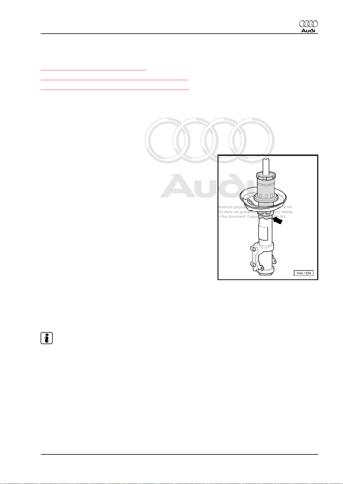
2.3 Releasing gas in Audi magnetic ride shock absorbers (front)
– Clamp magnetic ride shock absorber vertically in a vice.
WARNING
Safety goggles must be worn when drilling.
– Drill a 3 mm ∅ hole -arrow A- through outer tube of shock ab‐
sorber.
Note
Gas will escape during drilling.
– Drill a second 6 mm ∅ hole -arrow B- through outer tube of
shock absorber.
– Hold shock absorber over a drip tray and move piston rod up
and down several times through entire stroke until no more
fluid comes out.
2. Proper disposal of fluid-filled components 3
Page 10
Protected by copyright. Copying for private or commercial purposes, in part or in whole, is not
permitted unless authorised by AUDI AG. AUDI AG does not guarantee or accept any liability
with respect to the correctness of information in this document. Copyright by AUDI AG.
Audi TT 2007 ➤
Running gear, front-wheel drive and four-wheel drive - Edition 08.2010
2.4 Releasing gas in Audi magnetic ride shock absorbers (rear)
– Clamp magnetic ride shock absorber vertically in vice with pis‐
ton rod facing downwards.
WARNING
Safety goggles must be worn when drilling.
– Drill a 3 mm ∅ hole -arrow A- through outer tube of shock ab‐
sorber.
Note
Gas will escape during drilling.
– Drill a second 6 mm ∅ hole -arrow B- through outer tube of
shock absorber.
– Hold shock absorber over a drip tray and move piston rod up
and down several times through entire stroke until no more
fluid comes out.
4 Rep. gr.00 - Technical data
Page 11
Protected by copyright. Copying for private or commercial purposes, in part or in whole, is not
permitted unless authorised by AUDI AG. AUDI AG does not guarantee or accept any liability
with respect to the correctness of information in this document. Copyright by AUDI AG.
Running gear, front-wheel drive and four-wheel drive - Edition 08.2010
3 Checking shock absorbers
⇒ „3.1 Leaks at shock absorbers“, page 5
⇒ „3.2 Checking shock absorbers when removed“, page 5
⇒ „3.3 Checking shock absorbers on shock tester“, page 6
3.1 Leaks at shock absorbers
Shock absorbers are often replaced because of externally visible
leakage. Inspections on the test rig and in the vehicle have shown
that in the majority of cases this replacement is not justified.
Slight loss of fluid („sweating“) at the piston rod seal is not a rea‐
son for replacing a shock absorber. A shock absorber with slight
fluid leakage can be accepted as "OK" under the following con‐
ditions:
♦ Fluid seepage (as shown in the shaded part of the illustration)
is visible, but the fluid is dull and possibly dried by dust
♦ The fluid seepage extends only from the top shock absorber
seal (piston rod seal) down to the bottom spring plate
-arrow-.
Audi TT 2007 ➤
3.2 Checking shock absorbers when re‐
moved
Defective shock absorbers can be identified by loud rumbling
noises when driving, caused by wheel hopping, especially on bad
roads. Heavy fluid leakage is an additional visual indication.
Note
Shock absorbers are maintenance-free; shock absorber fluid can‐
not be topped up.
After removal, a shock absorber can be checked by hand as fol‐
lows:
– Compress shock absorber by hand.
♦ The piston rod should move smoothly over the entire stroke
with uniform resistance and without jolts.
– Release piston rod.
♦ If the shock absorber has sufficient gas pressure the piston
rod will return by itself to its original position.
3. Checking shock absorbers 5
Page 12
Protected by copyright. Copying for private or commercial purposes, in part or in whole, is not
permitted unless authorised by AUDI AG. AUDI AG does not guarantee or accept any liability
with respect to the correctness of information in this document. Copyright by AUDI AG.
Audi TT 2007 ➤
Running gear, front-wheel drive and four-wheel drive - Edition 08.2010
Note
♦
If this is not the case, the shock absorber does not necessarily
need to be renewed. Provided there has been no major loss
of fluid, it will still be as effective as a conventional shock ab‐
sorber.
♦
Even without gas pressure, the shock absorber will provide full
damping effect as long as there has been no major loss of fluid.
However, it may produce more noise.
3.3 Checking shock absorbers on shock tester
The shock tester allows shock absorbers to be tested without re‐
moving them from the vehicle. The damping effect can be as‐
sessed on the basis of the pointer deflection or the print-out.
Special tools and workshop equipment required
♦ Boge shock tester or
♦ Sachs shock tester -V.A.G 1975- or
♦ Maha shock absorber tester -VAS 1990-
Note
♦
Temperature +10 ... +40 °C.
♦
Driver in vehicle.
♦
Vehicle stationary.
♦
Correct tyre inflation pressure.
♦
Wheels of vehicle in a central and straight position on the tyre
contact plates.
♦
Front wheels in straight-ahead position.
♦
Handbrake not applied, brake pedal not depressed.
♦
Ignition on.
♦
Test mode active on vehicles with Audi magnetic ride (AMR)
- electronic damping control.
Activating test mode for Audi magnetic ride (AMR) - electronic
damping control
– Press shock absorber damping adjustment button -E387-
⇒ page 45 in centre console and hold for over 5 seconds.
Diode in shock absorber damping adjustment button -E387flashes during test mode.
– The test mode is deactivated when shock absorber damping
adjustment button -E387- ⇒ page 45 is pressed again, when
the ignition is switched off, or when the vehicle is driven at a
speed of at least 10 km/h.
Test results
The condition of the shock absorbers can only be evaluated as
follows:
♦ Satisfactory damping effect
or
♦ Unsatisfactory damping effect
6 Rep. gr.00 - Technical data
Page 13
Protected by copyright. Copying for private or commercial purposes, in part or in whole, is not
permitted unless authorised by AUDI AG. AUDI AG does not guarantee or accept any liability
with respect to the correctness of information in this document. Copyright by AUDI AG.
Running gear, front-wheel drive and four-wheel drive - Edition 08.2010
Note
♦
It is not possible to obtain more detailed readings specifying
the exact degree of impairment of damping effect.
♦
A forecast of the remaining service life is not permissible.
♦
Test results will be falsified if the suspension contacts the
bump stops when the readings are taken.
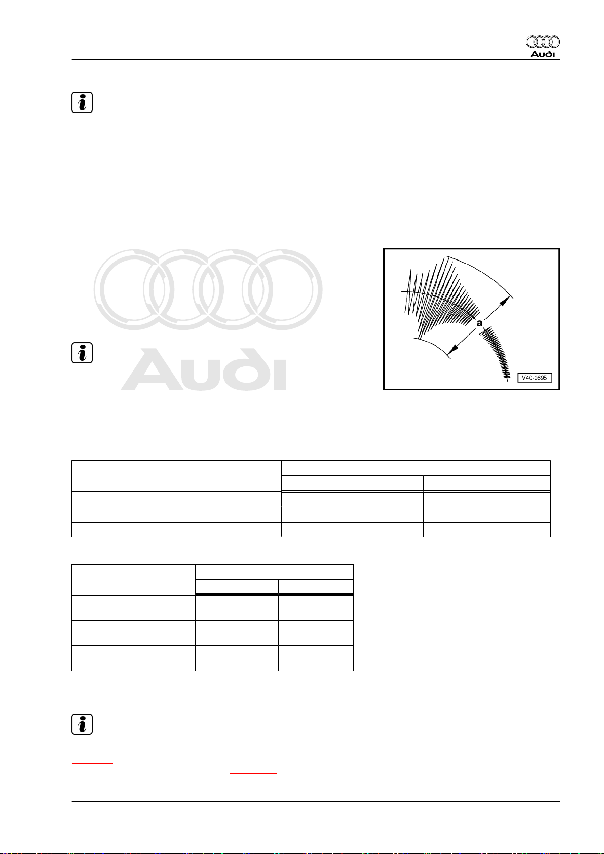
The following values apply only to tests conducted on the test
equipment listed above. If the stated values are exceeded, the
shock absorber action has deteriorated to such an extent that re‐
placement is recommended.
Example:
Maximum value = 70
♦ a = higher than 70: unsatisfactory damping effect
♦ a = lower than 70: satisfactory damping effect
Maximum values „a“ in mm
Audi TT 2007 ➤
Note
♦
If the reading is higher than the maximum value „a“ listed in
the table, the damping effect is unsatisfactory ⇒ renew the
shock absorber.
♦
If the reading is lower than the maximum value „a“ listed in the
table, the damping effect is satisfactory ⇒ the shock absorber
does not have to be renewed.
Front axle Damping effect
Inadequate Adequate
Standard running gear (1BA)
a = Greater than 60 a = Less than 60
Sports running gear (1BV) a = Greater than 60 a = Less than 60
Sports running gear (1BD) a = Greater than 60 a = Less than 60
Rear axle Damping effect
Inadequate Adequate
Standard running gear
(1BA)
a = Greater than60a = Less than
60
Sports running gear (1BV) a = Greater than60a = Less than
60
Sports running gear (1BD) a = Greater than60a = Greater
than 60
Vehicles with Audi magnetic ride (AMR) - electronic damping
control
Note
These values apply only when the test mode is activated
⇒ page 6 (in test mode, a diode flashes in the shock absorber
damping adjustment button -E387- ⇒ page 45 ).
3. Checking shock absorbers 7
Page 14
Protected by copyright. Copying for private or commercial purposes, in part or in whole, is not
permitted unless authorised by AUDI AG. AUDI AG does not guarantee or accept any liability
with respect to the correctness of information in this document. Copyright by AUDI AG.
Audi TT 2007 ➤
Running gear, front-wheel drive and four-wheel drive - Edition 08.2010
Front axle Damping effect
Inadequate Adequate
Sports running gear (1BL)
a = Greater than 50 a = Less than 50
Sports running gear (1BQ) a = Greater than 50 a = Less than 50
Rear axle Damping effect
Inadequate Adequate
Sports running gear (1BL)
a = Greater than50a = Less than
50
Sports running gear (1BQ) a = Greater than50a = Less than
50
8 Rep. gr.00 - Technical data
Page 15

Protected by copyright. Copying for private or commercial purposes, in part or in whole, is not
permitted unless authorised by AUDI AG. AUDI AG does not guarantee or accept any liability
with respect to the correctness of information in this document. Copyright by AUDI AG.
Running gear, front-wheel drive and four-wheel drive - Edition 08.2010
40 – Front suspension
1 General notes
⇒ „1.1 General information“, page 9
⇒ „1.2 Contact corrosion“, page 10
⇒ „1.3 Repairing threads in longitudinal member“, page 10
⇒ „1.4 Lifting suspension to unladen position“, page 11
⇒ „1.5 Exploded views of front axle“, page 13
1.1 General information
All contact surfaces must be cleaned when installing wax-coated
components. The contact surfaces must be free of wax and
grease.
Tightening torques refer to unoiled bolts and nuts.
Always renew self-locking bolts/nuts.
Always renew bolts and nuts which are tightened by turning
through a specified angle.
Load-bearing components and other suspension parts must not
be welded or straightened.
Do not subject coil springs to hammer blows or weld splashes and
do not make any new colour markings.
Do not perform welding or cutting operations (using power grind‐
ers) near the coil springs or suspension struts. Cover up coil
springs or suspension struts if necessary.
Make sketches or take photographs when unfastening or remov‐
ing and installing hydraulic or pneumatic pipes or electrical wires.
This ensures re-installation at the original location.
Any cable ties, brackets or fasteners removed during repair work
must be re-attached at their original standard locations.
Before fitting the outer joint in the wheel hub, apply a thin coat of
assembly paste to the splines on the outer joint ⇒ Electronic parts
catalogue .
When working on the vehicle, do not allow the drive shafts to hang
down under their own weight and never let the joints bend to such
an extent that they contact the end stop.
Do not attempt to move the vehicle without the drive shafts fitted;
this would result in wheel bearing damage. If the vehicle does
have to be moved, always note the following points:
– Fit an outer joint in place of the drive shaft.
– Tighten the outer joint to 120 Nm (twelve-point bolt) or 200 Nm
(hexagon bolt).
Bonded rubber bushes can only be turned to a limited extent. The
suspension must therefore always be in the unladen position or
the reference position when the suspension link attachments are
tightened.
♦ Lifting suspension to unladen position (vehicles with coil
springs)
⇒ „1.4 Lifting suspension to unladen position“, page 11
If the wheel alignment has to be checked and adjusted at a later
stage, all bolts and nuts which need to be slackened to make ad‐
justments should initially only be tightened to the specified torque
figure. After wheel alignment has been checked and adjusted,
Audi TT 2007 ➤
1. General notes 9
Page 16
Protected by copyright. Copying for private or commercial purposes, in part or in whole, is not
permitted unless authorised by AUDI AG. AUDI AG does not guarantee or accept any liability
with respect to the correctness of information in this document. Copyright by AUDI AG.
Audi TT 2007 ➤
Running gear, front-wheel drive and four-wheel drive - Edition 08.2010
bolts and nuts must then be fully tightened by turning them
through the specified angle.
WARNING
All bolts and nuts must be fully tightened according to specifi‐
cations before the vehicle is driven on public roads.
1.2 Contact corrosion
Contact corrosion can occur if unsuitable fasteners (bolts, nuts,
washers ...) are used.
For this reason, all the fasteners on the vehicle have a special
surface coating.
In addition, rubber parts, plastic parts and adhesives are made of
non-conductive material.
Always install new parts as listed in the Parts catalogue if you are
not sure whether used parts can be refitted.
Note:
♦ We recommend using only genuine replacement parts; these
have been tested and are compatible with aluminium.
♦ We recommend the use of Audi accessories.
♦ Damage resulting from contact corrosion is not covered under
the warranty.
1.3 Repairing threads in longitudinal mem‐
ber
Under certain circumstances it is possible to repair the threads in
the captive nuts in the longitudinal member.
♦ Each thread can only be repaired once.
♦ If a second repair is needed, the captive nut must be renewed.
WARNING
Always wear safety goggles when drilling.
♦ Have all thread repairs checked by foreman or supervisor.
♦ The thread insert must be of the same length as the thread in
the body.
♦ Repair any damage to underseal ⇒ Body Repairs; Rep. gr.
00 ; Corrosion protection measures
10 Rep. gr.40 - Front suspension
Page 17
Protected by copyright. Copying for private or commercial purposes, in part or in whole, is not
permitted unless authorised by AUDI AG. AUDI AG does not guarantee or accept any liability
with respect to the correctness of information in this document. Copyright by AUDI AG.
Running gear, front-wheel drive and four-wheel drive - Edition 08.2010
1.4 Lifting suspension to unladen position
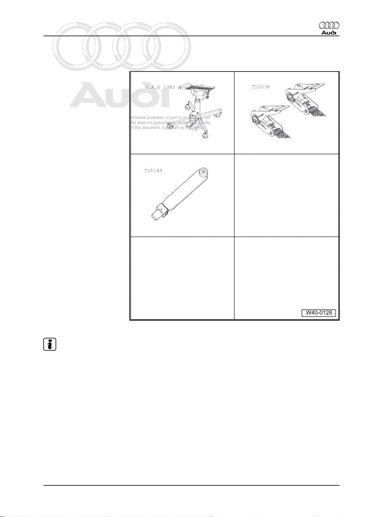
Special tools and workshop
equipment required
♦ Engine and gearbox jack -
V.A.G 1383 A-
♦ Tensioning strap -T10038-
♦ Support -T10149-
Audi TT 2007 ➤
Note
All bolts on running gear components with bonded rubber bushes
must always be tightened with the suspension in the unladen po‐
sition (vehicle unladen).
Bonded rubber bushes can only be turned to a limited extent.
Therefore, before tightening the bolts, suspension components
with bonded rubber bushes must be brought into a position cor‐
responding to the normal position of the unladen vehicle while
driving (unladen position).
Otherwise, the bush would be subject to torsion loading and its
service life would be shortened.
This position can be simulated on the lifting platform by raising
the appropriate part of the suspension with the engine and gear‐
box jack -V.A.G 1383 A- and support -T10149- .
1. General notes 11
Page 18
Protected by copyright. Copying for private or commercial purposes, in part or in whole, is not
permitted unless authorised by AUDI AG. AUDI AG does not guarantee or accept any liability
with respect to the correctness of information in this document. Copyright by AUDI AG.
Audi TT 2007 ➤
Running gear, front-wheel drive and four-wheel drive - Edition 08.2010
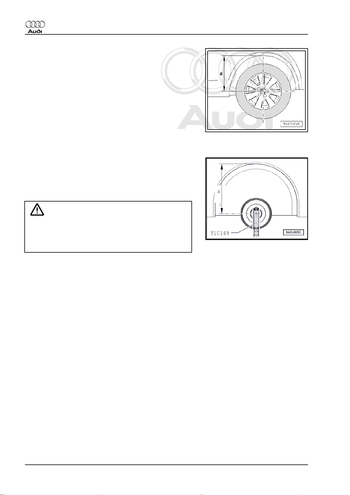
– Before commencing work, use measuring tape or similar to
measure dimension -a- from wheel centre to lower edge of
wheel housing.
This measurement must be taken with the suspension in the un‐
laden position (vehicle unladen).
– Make a note of the measured value. This will be needed when
tightening the bolts and/or nuts on the suspension.
Before raising wheel unit, secure vehicle to arms of lifting platform
using tensioning straps -T10038- .
If vehicle is not secured, there is a risk of it slipping off the lifting
platform.
– Turn wheel hub until one of the wheel bolt holes is at the top.
– Attach support -T10149- to wheel hub using wheel bolt.
– Raise wheel bearing housing with engine and gearbox jack -
V.A.G 1383 A- until distance -a- is obtained.
The bolts/nuts on the relevant suspension mountings must not be
tightened until the distance -a- between the wheel centre and the
lower edge of the wheel housing is the same as the distance
measured before commencing work.
WARNING
♦ Do not lift or lower the vehicle while the engine/gearbox
jack is under the vehicle.
♦ Do not leave engine and gearbox jack -V.A.G 1383 A- un‐
der vehicle for longer than necessary.
– Tighten relevant bolts/nuts.
– Lower wheel bearing housing.
– Pull out engine/gearbox jack from under vehicle.
– Remove support -T10149- .
12 Rep. gr.40 - Front suspension
Page 19
Protected by copyright. Copying for private or commercial purposes, in part or in whole, is not
permitted unless authorised by AUDI AG. AUDI AG does not guarantee or accept any liability
with respect to the correctness of information in this document. Copyright by AUDI AG.
Running gear, front-wheel drive and four-wheel drive - Edition 08.2010
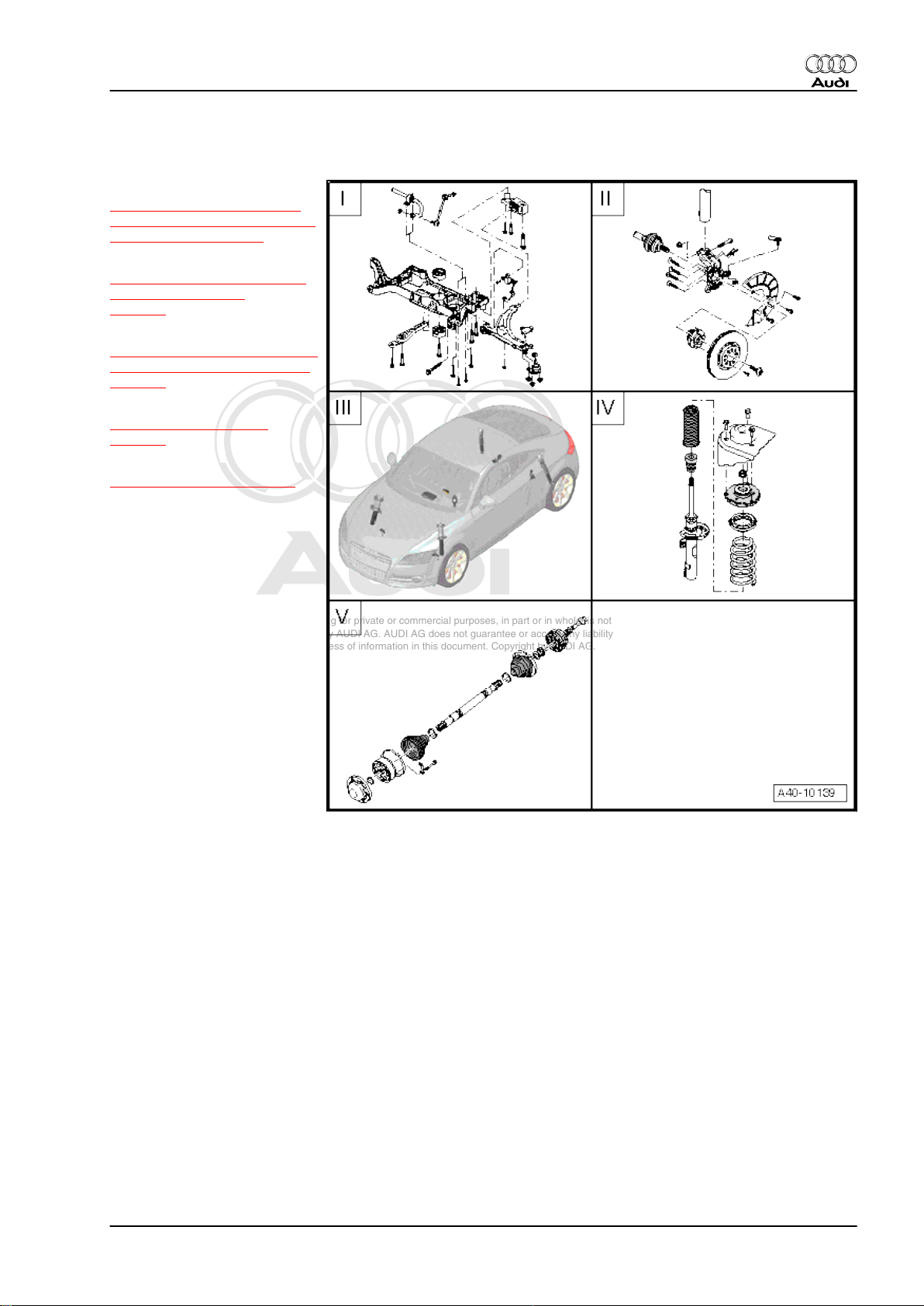
1.5 Exploded views of front axle
I -
⇒ „2 Subframe, anti-roll bar,
wishbone, swivel joint, vehicle
level sender“, page 14
II -
⇒ „3 Wheel bearing housing,
wheel bearing unit“,
page 39
III -
⇒ „4 Audi magnetic ride (AMR)
- electronic damping control“,
page 45
IV -
⇒ „5 Suspension strut“,
page 48
V -
⇒ „6 Drive shafts“, page 55
Audi TT 2007 ➤
1. General notes 13
Page 20
Protected by copyright. Copying for private or commercial purposes, in part or in whole, is not
permitted unless authorised by AUDI AG. AUDI AG does not guarantee or accept any liability
with respect to the correctness of information in this document. Copyright by AUDI AG.
Audi TT 2007 ➤
Running gear, front-wheel drive and four-wheel drive - Edition 08.2010
2 Subframe, anti-roll bar, wishbone,
swivel joint, vehicle level sender
⇒ „2.1 Exploded view of subframe, anti-roll bar, wishbone, swivel
joint, vehicle level sender“, page 15
⇒ „2.2 Removing and installing subframe“, page 17
⇒ „2.3 Servicing subframe“, page 22
⇒ „2.4 Locating subframe in position“, page 25
⇒ „2.5 Removing and installing anti-roll bar“, page 26
⇒ „2.6 Removing and installing wishbone and mounting bracket“,
page 27
⇒ „2.7 Renewing bonded rubber bush in wishbone“, page 31
⇒ „2.8 Renewing mounting bracket for wishbone“, page 34
⇒ „2.9 Removing and installing swivel joint“, page 35
⇒ „2.10 Checking swivel joint“, page 37
⇒ „2.11 Removing and installing front left vehicle level sender G78
and front right vehicle level sender G289 “, page 37
14 Rep. gr.40 - Front suspension
Page 21
Protected by copyright. Copying for private or commercial purposes, in part or in whole, is not
permitted unless authorised by AUDI AG. AUDI AG does not guarantee or accept any liability
with respect to the correctness of information in this document. Copyright by AUDI AG.
Audi TT 2007 ➤
Running gear, front-wheel drive and four-wheel drive - Edition 08.2010
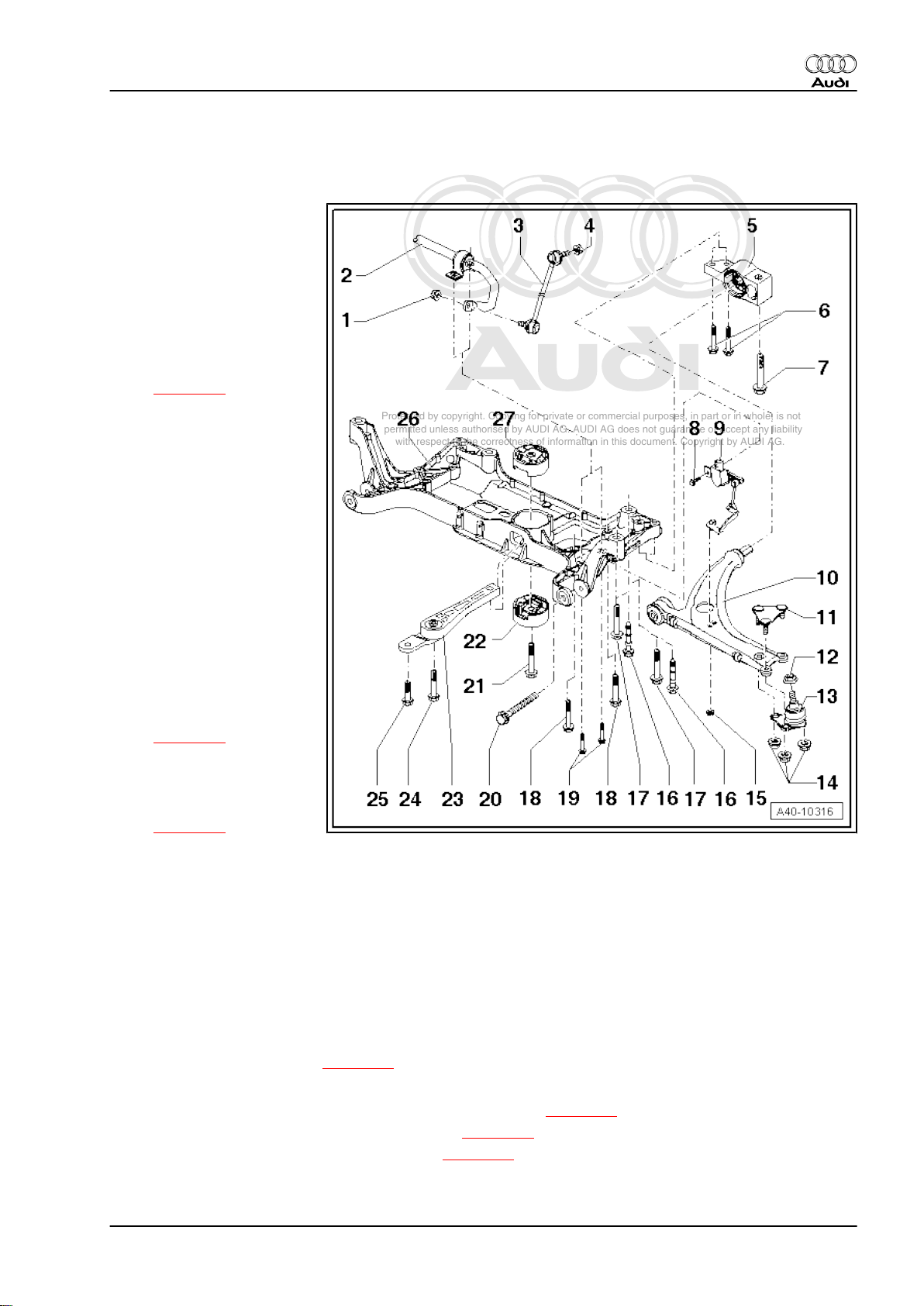
2.1 Exploded view of subframe, anti-roll bar, wishbone, swivel joint, vehicle level sender
1 - Nut
❑ 65 Nm
❑ When tightening, coun‐
terhold multi-point sock‐
et of joint pin
❑ Always renew if re‐
moved
2 - Anti-roll bar
❑ Removing and installing
⇒ page 26
❑ Different versions possi‐
ble. For correct version
refer to ⇒ Electronic
parts catalogue „ETKA“
3 - Coupling rod
❑ Link between anti-roll
bar and suspension
strut
4 - Nut
❑ 65 Nm
❑ When tightening, coun‐
terhold multi-point sock‐
et of joint pin
❑ Always renew if re‐
moved
5 - Mounting bracket
❑ Locating in position
⇒ page 26
❑ With bonded rubber
bush
❑ Renewing mounting
bracket for wishbone
⇒ page 34
6 - Bolt
❑ 50 Nm + 90°
❑ Always renew if removed
7 - Bolt
❑ 70 Nm + 90°
❑ Always renew if removed
8 - Bolt
❑ 9 Nm
9 - Front left vehicle level sender -G78- and front right vehicle level sender -G289-
❑ Removing and installing ⇒ page 37
10 - Wishbone
❑ Removing and installing wishbone and mounting bracket ⇒ page 27
❑ Renewing bonded rubber bush for wishbone ⇒ page 31
❑ Renewing mounting bracket for wishbone ⇒ page 34
11 - Retaining plate
❑ Always renew if removed
2. Subframe, anti-roll bar, wishbone, swivel joint, vehicle level sender 15
Page 22
Protected by copyright. Copying for private or commercial purposes, in part or in whole, is not
permitted unless authorised by AUDI AG. AUDI AG does not guarantee or accept any liability
with respect to the correctness of information in this document. Copyright by AUDI AG.
Audi TT 2007 ➤
Running gear, front-wheel drive and four-wheel drive - Edition 08.2010
12 - Nut
❑ 20 Nm + 90°
❑ Always renew if removed
13 - Swivel joint
❑ Removing and installing ⇒ page 35
❑ Checking ⇒ page 37
14 - Nut
❑ 40 Nm + 45°
❑ Always renew if removed
15 - Nut
❑ 9 Nm
16 - Bolt
❑ 70 Nm + 90°
❑ Different country-specific versions are possible; for correct version, refer to ⇒ Electronic parts catalogue
„ETKA“
❑ Note different thread lengths
❑ Positioned with indentation on bolt head at rear underbody attachment point
❑ Always renew if removed
17 - Bolt
❑ 70 Nm + 90°
❑ Different country-specific versions are possible; for correct version, refer to ⇒ Electronic parts catalogue
„ETKA“
❑ Always renew if removed
18 - Bolt
❑ 50 Nm + 90°
❑ Attachment for steering box
❑ Always renew if removed
19 - Bolt
❑ 20 Nm + 90°
❑ Attachment for anti-roll bar
❑ Always renew if removed
20 - Bolt
❑ 70 Nm + 180°
❑ Always renew if removed
❑ Suspension must be in unladen position when tightening ⇒ page 11
21 - Bolt
❑ 100 Nm + 90°
❑ Do not tighten until pendulum support is bolted to gearbox
❑ Always renew if removed
22 - Bonded rubber bush (bottom) for pendulum support
❑ Removing and installing ⇒ page 22
23 - Pendulum support
❑ Bolt to gearbox first, then to subframe
❑ Different versions are possible; for correct version, refer to ⇒ Electronic parts catalogue „ETKA“
24 - Bolt
❑ Tightening torque for vehicles with manual gearbox ⇒ Rep. gr. 34
❑ Tightening torque for vehicles with automatic gearbox ⇒ Rep. gr. 37
16 Rep. gr.40 - Front suspension
Page 23
Protected by copyright. Copying for private or commercial purposes, in part or in whole, is not
permitted unless authorised by AUDI AG. AUDI AG does not guarantee or accept any liability
with respect to the correctness of information in this document. Copyright by AUDI AG.
Audi TT 2007 ➤
Running gear, front-wheel drive and four-wheel drive - Edition 08.2010
25 - Bolt
❑ Tightening torque for vehicles with manual gearbox ⇒ Rep. gr. 34
❑ Tightening torque for vehicles with automatic gearbox ⇒ Rep. gr. 37
26 - Subframe
❑ Removing and installing ⇒ page 17
❑ Servicing subframe ⇒ page 22
❑ Locating subframe in position ⇒ page 25
❑ Different versions possible. For correct version refer to ⇒ Electronic parts catalogue „ETKA“
27 - Bonded rubber bush (top) for pendulum support
❑ Removing and installing ⇒ page 22
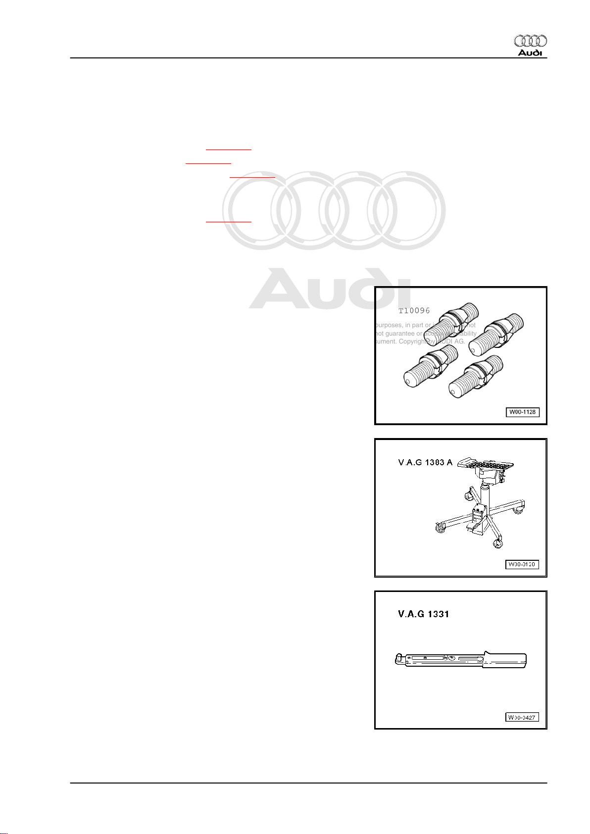
2.2 Removing and installing subframe
Special tools and workshop equipment required
♦ Locating pins -T10096-
♦ Engine and gearbox jack -V.A.G 1383 A-
♦ Torque wrench -V.A.G 1331-
2. Subframe, anti-roll bar, wishbone, swivel joint, vehicle level sender 17
Page 24
Protected by copyright. Copying for private or commercial purposes, in part or in whole, is not
permitted unless authorised by AUDI AG. AUDI AG does not guarantee or accept any liability
with respect to the correctness of information in this document. Copyright by AUDI AG.
Audi TT 2007 ➤
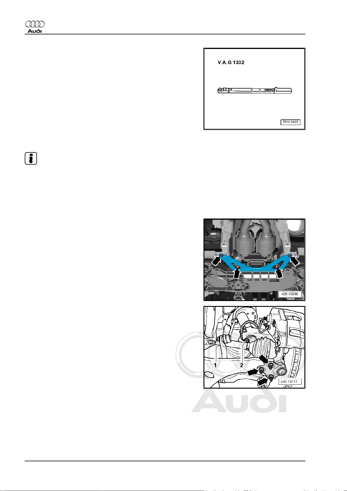
Running gear, front-wheel drive and four-wheel drive - Edition 08.2010
♦ Torque wrench -V.A.G 1332-
Removing
Note
The subframe is removed together with the anti-roll bar and wish‐
bones.
– Remove wheels.
– Detach noise insulation (bottom) ⇒ Rep. gr. 66 .
– Remove frame for noise insulation ⇒ Rep. gr. 50 .
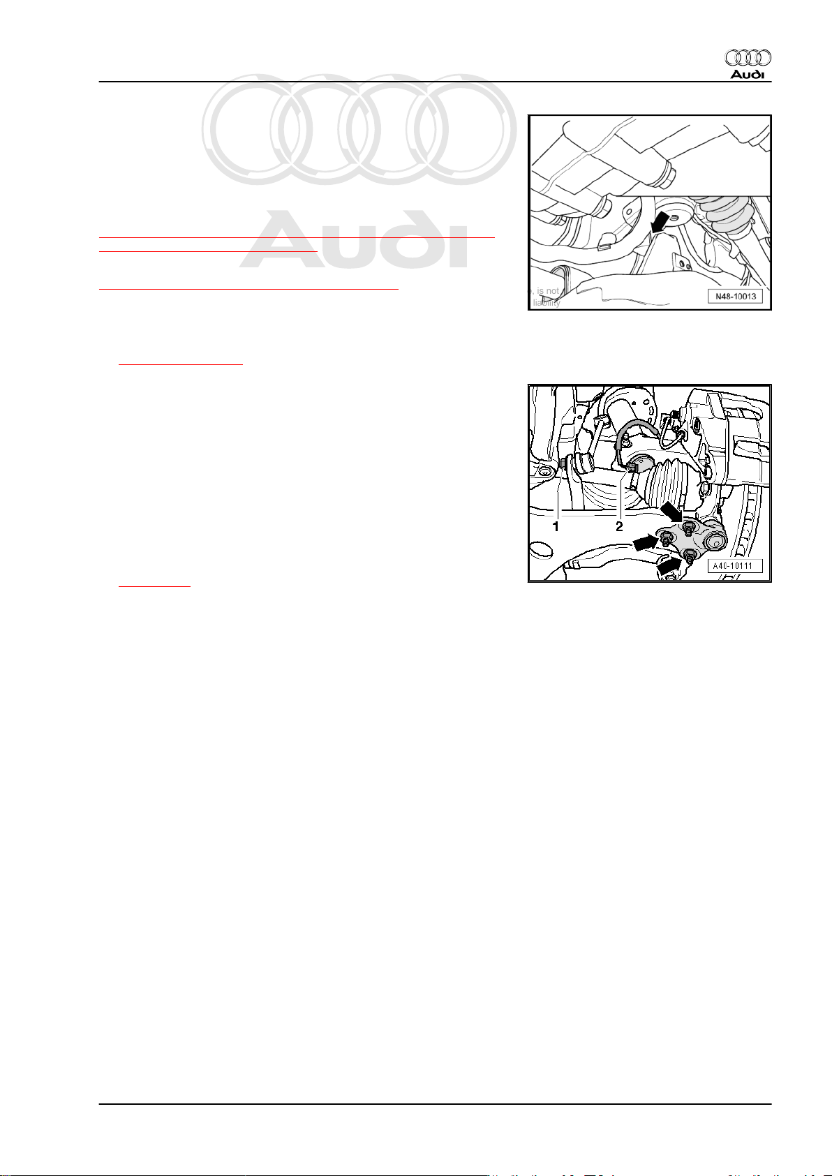
– Remove bolts -arrows- for exhaust bracket.
– Remove nut -1-.
18 Rep. gr.40 - Front suspension
Page 25
Protected by copyright. Copying for private or commercial purposes, in part or in whole, is not
permitted unless authorised by AUDI AG. AUDI AG does not guarantee or accept any liability
with respect to the correctness of information in this document. Copyright by AUDI AG.
Running gear, front-wheel drive and four-wheel drive - Edition 08.2010
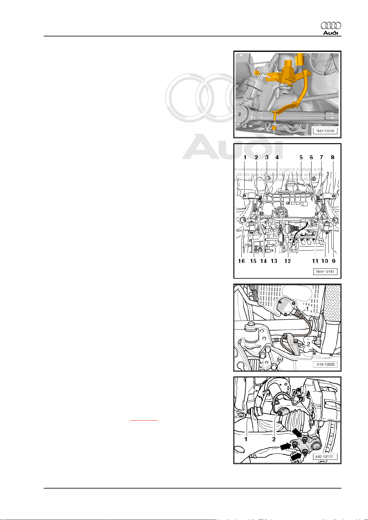
– On vehicles with vehicle level sender, unplug connector and
unscrew nut from linkage at wishbone.
– Unscrew bolts -13- and remove pendulum support from gear‐
box.
Audi TT 2007 ➤
– Unplug connector -1- for oil level and oil temperature sender
-G266- and unclip wiring from bracket -2-.
– Mark positions of nuts -arrows- with felt pen on both sides of
vehicle.
– Remove nuts -arrows- on both sides of vehicle.
– Pull wishbone out of swivel joint.
– Locate subframe in position ⇒ page 25 .
2. Subframe, anti-roll bar, wishbone, swivel joint, vehicle level sender 19
Page 26
Protected by copyright. Copying for private or commercial purposes, in part or in whole, is not
permitted unless authorised by AUDI AG. AUDI AG does not guarantee or accept any liability
with respect to the correctness of information in this document. Copyright by AUDI AG.
Audi TT 2007 ➤
Running gear, front-wheel drive and four-wheel drive - Edition 08.2010
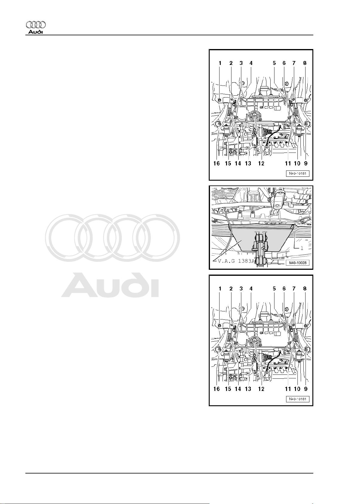
– Remove bolts -3- and -6- for steering box.
– Position engine and gearbox jack -V.A.G 1383 A- with suitable
wooden block -1- under subframe and press subframe up‐
wards lightly.
– Remove bolts -4- and -5-.
– Lower subframe with attached components approx. 30 mm
and pry threaded sleeves for steering box out of holes in sub‐
frame.
– Secure steering box to body.
20 Rep. gr.40 - Front suspension
Page 27
Protected by copyright. Copying for private or commercial purposes, in part or in whole, is not
permitted unless authorised by AUDI AG. AUDI AG does not guarantee or accept any liability
with respect to the correctness of information in this document. Copyright by AUDI AG.
Running gear, front-wheel drive and four-wheel drive - Edition 08.2010
– Detach cable guide from subframe -arrow-.
– Lower subframe with attached components.
Installing
Installation is performed in reverse sequence; note the following:
Tightening torques
⇒ „2.1 Exploded view of subframe, anti-roll bar, wishbone, swivel
joint, vehicle level sender“, page 15
Tightening torques
⇒ „4 Electro-mechanical steering box“, page 264
Threaded sleeves of steering box must be located in subframe
holes.
– Always renew retaining plate if removed
⇒ Item 11 (page 15) .
– Align position of nuts -arrows- according to markings made on
removal and tighten nuts.
– Install frame for noise insulation ⇒ Rep. gr. 50 .
– Install noise insulation ⇒ Rep. gr. 66 .
– On vehicles with electronic damping control (Audi magnetic
ride), re-adapt reference position ⇒ Vehicle diagnostic, testing
and information system VAS 5051.
– On vehicles with automatic headlight range control, carry out
basic adjustment of headlights ⇒ Rep. gr. 94 .
– Check and adjust wheel alignment as required, see chart
⇒ page 243 .
Audi TT 2007 ➤
2. Subframe, anti-roll bar, wishbone, swivel joint, vehicle level sender 21
Page 28
Protected by copyright. Copying for private or commercial purposes, in part or in whole, is not
permitted unless authorised by AUDI AG. AUDI AG does not guarantee or accept any liability
with respect to the correctness of information in this document. Copyright by AUDI AG.
Audi TT 2007 ➤
Running gear, front-wheel drive and four-wheel drive - Edition 08.2010
2.3 Servicing subframe
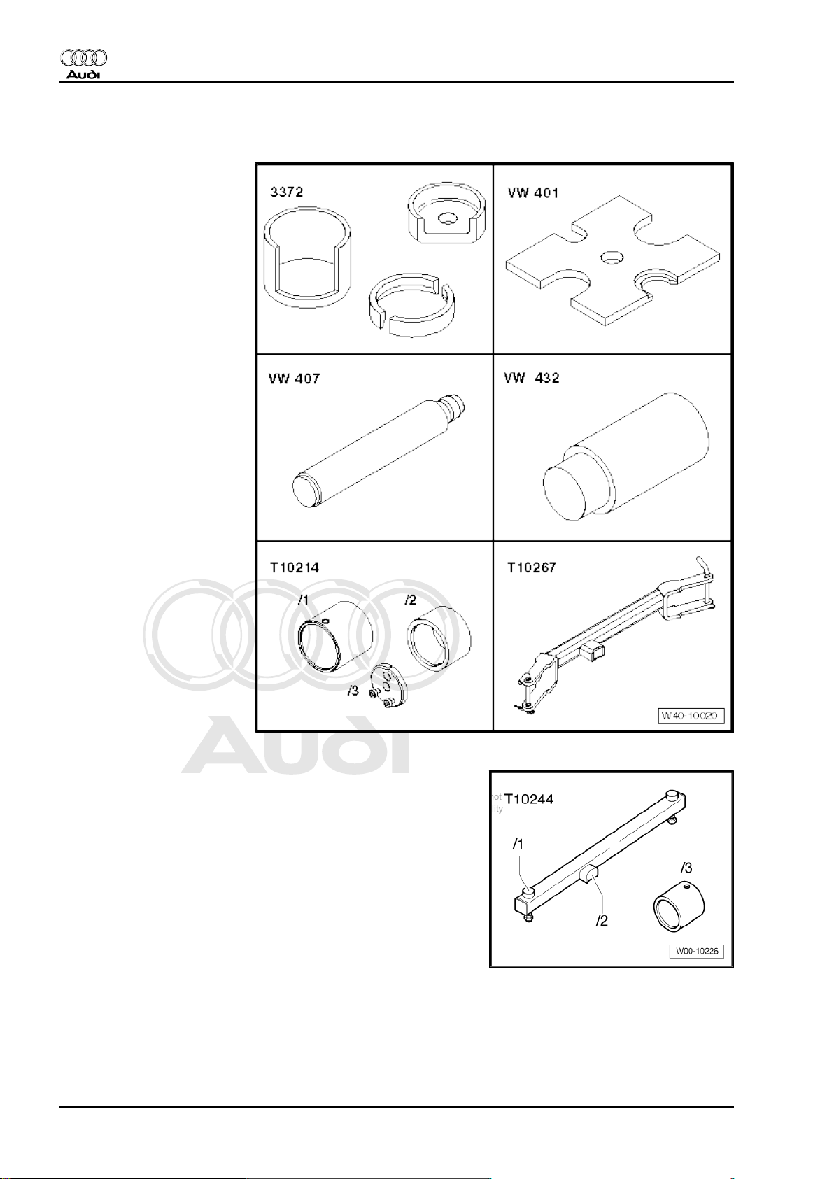
Special tools and workshop
equipment required
♦ Removal tool -3372-
♦ Thrust plate -VW 401-
♦ Press tool -VW 407-
♦ Press tool -VW 432-
♦ Assembly tool -T10214-
♦ Assembly tool -T10267-
♦ Tube from assembly tool -T10244/3-
– Remove subframe ⇒ page 17 .
– Detach pendulum support from subframe.
22 Rep. gr.40 - Front suspension
Page 29
Protected by copyright. Copying for private or commercial purposes, in part or in whole, is not
permitted unless authorised by AUDI AG. AUDI AG does not guarantee or accept any liability
with respect to the correctness of information in this document. Copyright by AUDI AG.
Running gear, front-wheel drive and four-wheel drive - Edition 08.2010
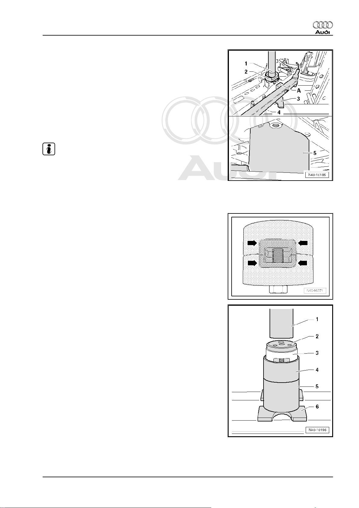
Pressing out bonded rubber bush
– Attach assembly tool -T10267- -4- to subframe. Secure re‐
taining pins of tool with locking pins.
1 - Press tool -VW 407-
2 - Thrust piece -3372/1-
3 - Thrust plate -VW 401-
4 - Assembly tool -T10267-
5 - Tube -T10244/3-
– Press out both bonded rubber bushes together as shown.
Note
♦
The flattened side of press tool -3372/1- must face the attach‐
ment -A- on assembly tool -T10267- , otherwise the attach‐
ment can be damaged.
♦
The tube -T10244/3- has two different internal diameters. The
subframe must be positioned on the larger diameter of the tube
-T10244/3- .
Audi TT 2007 ➤
Pressing in bonded rubber bush
– Bolt together both bonded rubber bushes with the genuine bolt
(the two recesses -arrows- must be exactly above each other).
– Insert the assembled bonded rubber bushes into the larger
diameter of tube -T10214/2- (with bolt head pointing down‐
wards).
1 - Press tool -VW 432-
2 - Press tool -T10214/3- without bolts.
3 - Bonded rubber bush
4 - Tube -T10214/2-
5 - Tube -T10214/1-
6 - Thrust plate -VW 401-
2. Subframe, anti-roll bar, wishbone, swivel joint, vehicle level sender 23
Page 30
Protected by copyright. Copying for private or commercial purposes, in part or in whole, is not
permitted unless authorised by AUDI AG. AUDI AG does not guarantee or accept any liability
with respect to the correctness of information in this document. Copyright by AUDI AG.
Audi TT 2007 ➤
Running gear, front-wheel drive and four-wheel drive - Edition 08.2010
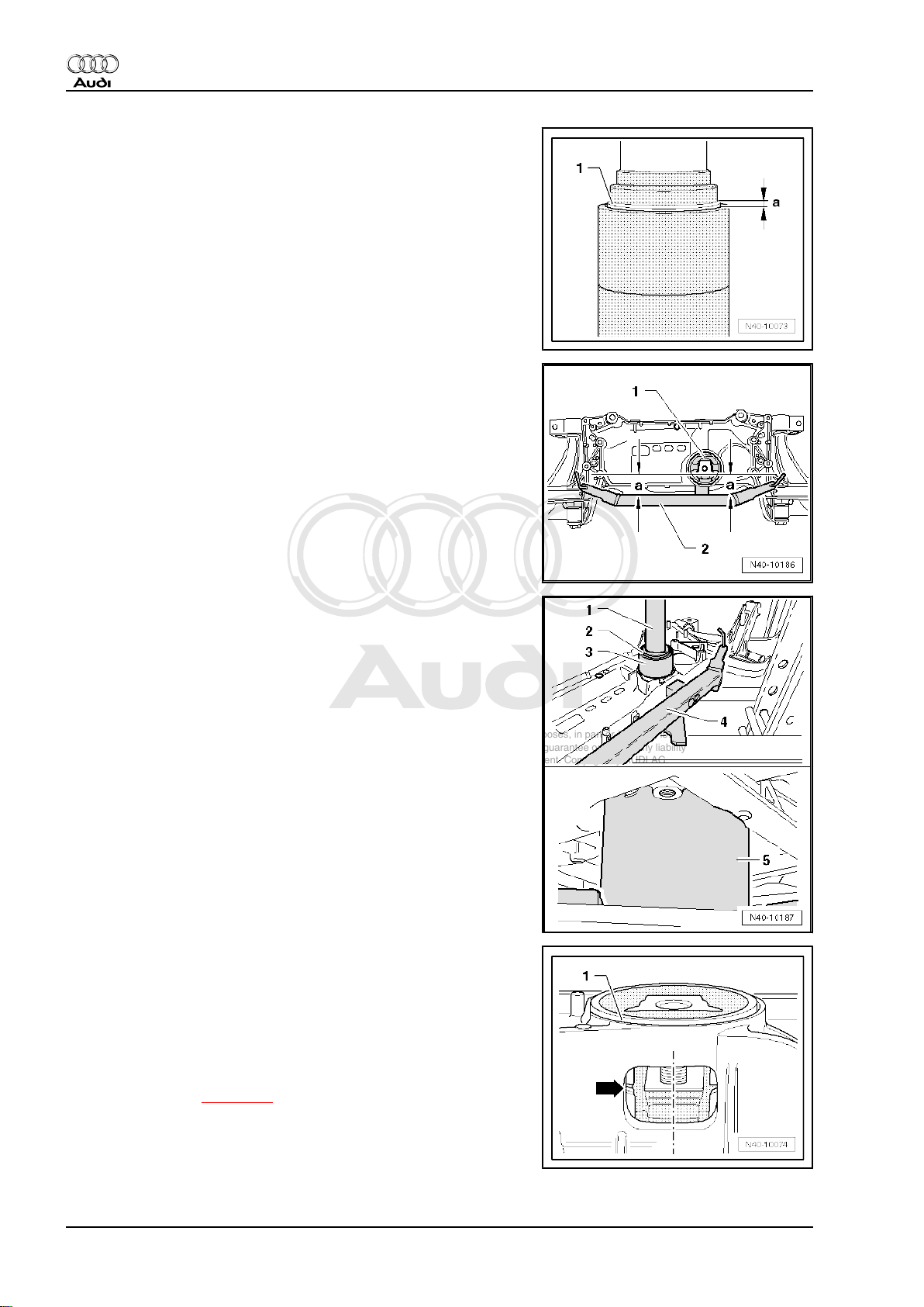
– Press in bonded rubber bushes -1- until dimension -a- is ob‐
tained.
Dimension -a- = 2 - 3 mm.
– Align tube -T10214/2- containing pressed-in bonded rubber
bushes on subframe. The corners of the inner core of the bush
-1- should lie parallel with the edge of assembly tool -T10267-
-2-.
The distance -a- must be identical on both sides to ensure parallel
alignment.
– Place subframe onto smaller internal diameter of tube -
T10244/3- .
– Press in bushes as far as stop (until a force of 20 kN is at‐
tained).
1 - Press tool -VW 407-
2 - Thrust piece -T10214/3-
3 - Tube -T10214/2-
4 - Assembly tool -T10267-
5 - Tube -T10244/3-
– Detach assembly tool -T10267- from subframe and check
pressed-in bonded rubber bushes for proper seating.
• The outer diameter -1- of the two bonded rubber bushes may
project up to 2 mm above the edge in the vicinity of the aper‐
ture for the pendulum support.
• The recesses of the bonded rubber bushes must be positioned
in the centre of the aperture in the subframe.
• There may be a gap -arrow- between the bonded rubber bush‐
es.
– Install subframe ⇒ page 17 .
24 Rep. gr.40 - Front suspension
Page 31

Protected by copyright. Copying for private or commercial purposes, in part or in whole, is not
permitted unless authorised by AUDI AG. AUDI AG does not guarantee or accept any liability
with respect to the correctness of information in this document. Copyright by AUDI AG.
Running gear, front-wheel drive and four-wheel drive - Edition 08.2010
2.4 Locating subframe in position
Special tools and workshop equipment required
♦ Locating pins -T10096-
♦ Torque wrench -V.A.G 1331-
Audi TT 2007 ➤
Installing locating pins -T10096-
The locating pins -T10096- must be screwed in one after the other
at positions -1-, -8-, -9- and -16- to locate the subframe with wish‐
bones in position.
– Screw in locating pins -T10096- in place of securing bolts and
tighten to 20 Nm.
2. Subframe, anti-roll bar, wishbone, swivel joint, vehicle level sender 25
Page 32

Protected by copyright. Copying for private or commercial purposes, in part or in whole, is not
permitted unless authorised by AUDI AG. AUDI AG does not guarantee or accept any liability
with respect to the correctness of information in this document. Copyright by AUDI AG.
Audi TT 2007 ➤
Running gear, front-wheel drive and four-wheel drive - Edition 08.2010
Locating mounting bracket in position
Locating subframe in position
The front axle is now fixed in position.
Removing locating pins -T10096-
Installation is carried out in the reverse sequence. When instal‐
ling, remove locating pins -T10096- one after the other and screw
in new securing bolts in their place.
Tightening torques
⇒ „2.1 Exploded view of subframe, anti-roll bar, wishbone, swivel
joint, vehicle level sender“, page 15
2.5 Removing and installing anti-roll bar
Special tools and workshop equipment required
♦ Locating pins -T10096-
♦ Engine and gearbox jack -V.A.G 1383 A-
26 Rep. gr.40 - Front suspension
Page 33

Protected by copyright. Copying for private or commercial purposes, in part or in whole, is not
permitted unless authorised by AUDI AG. AUDI AG does not guarantee or accept any liability
with respect to the correctness of information in this document. Copyright by AUDI AG.
Running gear, front-wheel drive and four-wheel drive - Edition 08.2010
♦ Torque wrench -V.A.G 1331-
♦ Torque wrench -V.A.G 1332-
Audi TT 2007 ➤
Removing
– Remove subframe ⇒ page 17
– Unbolt anti-roll bar from subframe -11 and 14-.
– Remove anti-roll bar.
Installing
Installation is performed in reverse sequence; note the following:
Tightening torques
⇒ „2.1 Exploded view of subframe, anti-roll bar, wishbone, swivel
joint, vehicle level sender“, page 15
Tightening torques
⇒ „4 Electro-mechanical steering box“, page 264
– Install subframe ⇒ page 17 .
– Always renew retaining plate if removed
⇒ Item 11 (page 15) .
2.6 Removing and installing wishbone and mounting bracket
Special tools and workshop equipment required
2. Subframe, anti-roll bar, wishbone, swivel joint, vehicle level sender 27
Page 34

Protected by copyright. Copying for private or commercial purposes, in part or in whole, is not
permitted unless authorised by AUDI AG. AUDI AG does not guarantee or accept any liability
with respect to the correctness of information in this document. Copyright by AUDI AG.
Audi TT 2007 ➤
Running gear, front-wheel drive and four-wheel drive - Edition 08.2010
♦ Locating pins -T10096-
♦ Torque wrench -V.A.G 1332-
♦ Torque wrench -V.A.G 1331-
Removing
– Remove wheel.
– Detach noise insulation (bottom) ⇒ Rep. gr. 66 .
– On vehicles with vehicle level sender, unscrew nut from link‐
age at wishbone.
28 Rep. gr.40 - Front suspension
Page 35

Protected by copyright. Copying for private or commercial purposes, in part or in whole, is not
permitted unless authorised by AUDI AG. AUDI AG does not guarantee or accept any liability
with respect to the correctness of information in this document. Copyright by AUDI AG.
Running gear, front-wheel drive and four-wheel drive - Edition 08.2010
– Mark positions of nuts -arrows- with felt pen.
– Unscrew nuts -arrows-.
– Pull wheel bearing housing with swivel joint out of wishbone.
– Screw in locating pins -T10096- in place of bolt -1- (left-side)
and bolt -8- (right-side) and tighten locating pins to 20 Nm.
Caution
The locating pins -T10096- must not be tightened to more than
20 Nm, otherwise the threads of the locating pins will be dam‐
aged.
Audi TT 2007 ➤
– Remove bolts -1-.
2. Subframe, anti-roll bar, wishbone, swivel joint, vehicle level sender 29
Page 36

Protected by copyright. Copying for private or commercial purposes, in part or in whole, is not
permitted unless authorised by AUDI AG. AUDI AG does not guarantee or accept any liability
with respect to the correctness of information in this document. Copyright by AUDI AG.
Audi TT 2007 ➤
Running gear, front-wheel drive and four-wheel drive - Edition 08.2010
– Unscrew bolt -15- on left side of vehicle or bolt -10- on right
side.
Note
If bolt -15- or -10- cannot be unscrewed, the subframe must be
removed on these vehicles ⇒ page 17 .
– Remove wishbone.
Installing
Installation is performed in reverse sequence; note the following:
Tightening torques
⇒ „2.1 Exploded view of subframe, anti-roll bar, wishbone, swivel
joint, vehicle level sender“, page 15
– Fit bolt -15- on left side of vehicle or bolt -10- on right side, and
tighten hand-tight.
– Always renew retaining plate if removed
⇒ Item 11 (page 15) .
– Align position of nuts -arrows- according to markings made on
removal and tighten nuts.
Note
♦
Bonded rubber bushes can only be turned to a limited extent.
The suspension mountings must therefore only be tightened
when the suspension is in the unladen position or reference
position.
♦
Lifting suspension to unladen position (vehicles with coil
springs) ⇒ page 11
30 Rep. gr.40 - Front suspension
Page 37

Protected by copyright. Copying for private or commercial purposes, in part or in whole, is not
permitted unless authorised by AUDI AG. AUDI AG does not guarantee or accept any liability
with respect to the correctness of information in this document. Copyright by AUDI AG.
Running gear, front-wheel drive and four-wheel drive - Edition 08.2010
– With vehicle in unladen position ⇒ page 11 , tighten bolt -15-
on left side of vehicle or bolt -10- on right side.
– On vehicles with electronic damping control (Audi magnetic
ride), re-adapt reference position ⇒ Vehicle diagnostic, testing
and information system VAS 5051.
– On vehicles with automatic headlight range control, carry out
basic adjustment of headlights ⇒ Rep. gr. 94 .
– Check and adjust wheel alignment as required, see chart
⇒ page 243 .
2.7 Renewing bonded rubber bush in wishbone
Audi TT 2007 ➤
Special tools and workshop
equipment required
♦ Assembly tool -T10219-
♦ Thrust plate -VW 402-
♦ Press tool -VW 411-
2. Subframe, anti-roll bar, wishbone, swivel joint, vehicle level sender 31
Page 38

Protected by copyright. Copying for private or commercial purposes, in part or in whole, is not
permitted unless authorised by AUDI AG. AUDI AG does not guarantee or accept any liability
with respect to the correctness of information in this document. Copyright by AUDI AG.
Audi TT 2007 ➤
Running gear, front-wheel drive and four-wheel drive - Edition 08.2010
Pressing out bonded rubber bush
– Press out bonded rubber bush as shown.
1 - Press tool -VW 411-
2 - Tube -T10219/1-
3 - Thrust plate -VW 402-
Pressing in bonded rubber bush
Note installation position of bonded rubber bush: retaining
grooves -arrows- must be aligned symmetrically relative to axis
of wishbone.
Beads -1 and 2- face towards front of vehicle as shown in illus‐
tration.
• The bonded rubber bush must be applied at an angle to pre‐
vent damage when pressing in. The bush will then straighten
up as it is pressed in.
– Apply assembly lubricant ⇒ Electronic parts catalogue (diluted
1:20 with water) to outside of bonded rubber bush.
– Apply bonded rubber bush at an angle (towards wishbone).
Lip -arrow- must slide into hole as shown.
1 - Mandrel -T10219/2-
2 - Tube -T10219/1-
3 - Thrust plate -VW 402-
32 Rep. gr.40 - Front suspension
Page 39

Protected by copyright. Copying for private or commercial purposes, in part or in whole, is not
permitted unless authorised by AUDI AG. AUDI AG does not guarantee or accept any liability
with respect to the correctness of information in this document. Copyright by AUDI AG.
Running gear, front-wheel drive and four-wheel drive - Edition 08.2010
– Press in bonded rubber bush until core of bush -1- is level with
hole in wishbone -2-.
– Press back bush slightly in wishbone.
1 - Tube -T10219/1-
2 - Thrust plate -VW 402-
Audi TT 2007 ➤
Dimensions -a- and -b- must be equal.
2. Subframe, anti-roll bar, wishbone, swivel joint, vehicle level sender 33
Page 40

Protected by copyright. Copying for private or commercial purposes, in part or in whole, is not
permitted unless authorised by AUDI AG. AUDI AG does not guarantee or accept any liability
with respect to the correctness of information in this document. Copyright by AUDI AG.
Audi TT 2007 ➤
Running gear, front-wheel drive and four-wheel drive - Edition 08.2010
2.8 Renewing mounting bracket for wishbone
Special tools and workshop
equipment required
♦ Press tool -VW 411-
♦ Thrust plate -VW 401-
♦ Thrust plate -VW 402-
♦ Tube -VW 426-
♦ Press tool -VW 412-
♦ Assembly tool -T10219-
Pressing mounting bracket off wishbone
Note
Hold wishbone while pressing it out
1 - Thrust plate -VW 401-
2 - Press tool -VW 411-
3 - Thrust plate -VW 402-
– Press off mounting bracket with bonded rubber bush from
wishbone.
34 Rep. gr.40 - Front suspension
Page 41

Protected by copyright. Copying for private or commercial purposes, in part or in whole, is not
permitted unless authorised by AUDI AG. AUDI AG does not guarantee or accept any liability
with respect to the correctness of information in this document. Copyright by AUDI AG.
Running gear, front-wheel drive and four-wheel drive - Edition 08.2010
Pressing mounting bracket onto wishbone
– Apply assembly lubricant ⇒ Electronic parts catalogue (diluted
1:20 with water) to hexagon flats of wishbone.
– Carefully press mounting bracket onto wishbone as far as it
will go.
1 - Press tool -VW 412-
2 - Tube -VW 426-
3 - Mounting bracket with bonded rubber bush
4 - Wishbone
5 - Tube T10219/1 from assembly tool -T10219-
6 - Thrust plate -VW 401-
2.9 Removing and installing swivel joint
Audi TT 2007 ➤
Special tools and workshop
equipment required
♦ Ball joint puller -3287 A-
♦ Angle wrench -V.A.G 1756-
♦ Ring spanner insert -
V.A.G 1332/10-
2. Subframe, anti-roll bar, wishbone, swivel joint, vehicle level sender 35
Page 42

Protected by copyright. Copying for private or commercial purposes, in part or in whole, is not
permitted unless authorised by AUDI AG. AUDI AG does not guarantee or accept any liability
with respect to the correctness of information in this document. Copyright by AUDI AG.
Audi TT 2007 ➤
Running gear, front-wheel drive and four-wheel drive - Edition 08.2010
Removing
– Remove wheel.
– On vehicles with vehicle level sender, unscrew nut from link‐
age at wishbone.
– Mark positions of nuts -arrows- with felt pen.
– Unscrew nuts -arrows-.
– Disengage wishbone from swivel joint.
– Apply ball joint puller 3287 A to swivel joint as shown.
– Press swivel joint out of wheel bearing housing.
WARNING
When the swivel joint is pressed out, it will release suddenly
from the wheel bearing housing and could cause injury.
Installing
Installation is performed in reverse sequence; note the following:
Tightening torques
⇒ „2.1 Exploded view of subframe, anti-roll bar, wishbone, swivel
joint, vehicle level sender“, page 15
– Install new self-locking nut, and counterhold with Torx key -
T40- -item 1-.
Note
Commercially available ring spanner type sockets (18 mm) can
also be used instead of ring spanner insert -V.A.G 1332/10- .
– Always renew retaining plate if removed
⇒ Item 11 (page 15) .
36 Rep. gr.40 - Front suspension
Page 43

Protected by copyright. Copying for private or commercial purposes, in part or in whole, is not
permitted unless authorised by AUDI AG. AUDI AG does not guarantee or accept any liability
with respect to the correctness of information in this document. Copyright by AUDI AG.
Running gear, front-wheel drive and four-wheel drive - Edition 08.2010
– Align position of nuts -arrows- according to markings made on
removal and tighten nuts.
– On vehicles with electronic damping control (Audi magnetic
ride), re-adapt reference position ⇒ Vehicle diagnostic, testing
and information system VAS 5051.
– On vehicles with automatic headlight range control, carry out
basic adjustment of headlights ⇒ Rep. gr. 94 .
– Check and adjust wheel alignment as required, see chart
⇒ page 243 .
2.10 Checking swivel joint
Checking axial play
– Pull wishbone firmly downwards and press back up again.
Audi TT 2007 ➤
Checking radial play
– Press bottom of wheel firmly inwards and outwards.
Note
♦
Observe the swivel joint while performing the tests.
♦
There should be no perceptible or visible „play“ when carrying
out both tests.
♦
Take into account any existing wheel bearing play or „play“ in
upper suspension strut mounting.
♦
Check rubber boot for damage, renew swivel joint if necessa‐
ry.
2.11 Removing and installing front left vehicle
level sender -G78- and front right vehi‐
cle level sender -G289-
General notes:
Vehicles with electronic damping control (Audi magnetic ride)
and/or gas discharge headlights have automatic headlight range
control fitted as standard equipment ⇒ Rep. gr. 94 .
The electronic damping control (Audi magnetic ride) and the au‐
tomatic headlight range control functions require information on
the compression and rebound travel at the front and rear sus‐
pension.
For this purpose, the position of the left/right wishbone in relation
to the body is transferred to the front left vehicle level sender G78- and the front right vehicle level sender -G289- via a coupling
rod. The senders then transmit electrical signals to the electroni‐
2. Subframe, anti-roll bar, wishbone, swivel joint, vehicle level sender 37
Page 44

Protected by copyright. Copying for private or commercial purposes, in part or in whole, is not
permitted unless authorised by AUDI AG. AUDI AG does not guarantee or accept any liability
with respect to the correctness of information in this document. Copyright by AUDI AG.
Audi TT 2007 ➤
Running gear, front-wheel drive and four-wheel drive - Edition 08.2010
cally controlled damping control unit -J250- and/or the gas dis‐
charge light control units (left/right) -J343/344- .
Servicing gas discharge light control unit (left/right) -J343/344- ⇒
Rep. gr. 94 .
On the rear axle these signals are supplied by the rear left vehicle
level sender -G76- and rear right vehicle level sender -G77- to the
electronically controlled damping control unit -J250- and/or the
gas discharge light control units (left/right) -J343/344- .
These signals are required for calculating the current attitude of
the vehicle.
The automatic headlight range control reacts to changes in the
suspension height (attitude of the vehicle).
The following situations may produce a change in the suspension
height:
♦ Towing a trailer/caravan
♦ Different loads (vehicle unladen, partly laden or fully laden)
The vehicle level sender is only available as a replacement part
complete with coupling rod and upper and lower retaining plates.
Note
The basic headlight setting must always be checked and, on ve‐
hicles with electronic damping control (Audi magnetic ride), the
reference position of the suspension must always be re-adapted
in the following cases:
♦ Following assembly work on vehicle level sender
♦ If wishbone has been removed and installed
♦ If the bolted connections -2- or -5- have been unfastened
Removing
– Unplug connector.
– Remove nut -5-.
– Remove bolt -2-.
– Take out vehicle level sender -3-.
Installing
Installation is carried out in the reverse sequence. Note the fol‐
lowing points:
Locating hook on coupling rod must engage on wishbone.
Lever of sender must face outwards.
Tightening torques ⇒ page 15
– On vehicles with electronic damping control (Audi magnetic
ride), re-adapt reference position ⇒ Vehicle diagnostic, testing
and information system VAS 5051.
– Perform basic setting of headlights ⇒ Rep. gr. 94 .
38 Rep. gr.40 - Front suspension
Page 45

Protected by copyright. Copying for private or commercial purposes, in part or in whole, is not
permitted unless authorised by AUDI AG. AUDI AG does not guarantee or accept any liability
with respect to the correctness of information in this document. Copyright by AUDI AG.
Audi TT 2007 ➤
Running gear, front-wheel drive and four-wheel drive - Edition 08.2010
3 Wheel bearing housing, wheel bear‐
ing unit
⇒ „3.1 Exploded view of wheel bearing housing and wheel bearing
unit“, page 39
⇒ „3.2 Removing and installing wheel bearing housing“,
page 40
⇒ „3.3 Removing and installing wheel bearing unit“, page 43
3.1 Exploded view of wheel bearing housing and wheel bearing unit
1 - Suspension strut
2 - Track rod ball joint
3 - Bolt
❑ 70 Nm + 90°
❑ Always renew if re‐
moved
❑ Threaded end of bolt
points in direction of
travel
4 - Bolt
❑ 8 Nm
5 - Front left speed sensor G47- / front right speed sensor
-G45-
❑ Before inserting sensor,
clean inner surface of fit‐
ting hole and coat with
grease G 000 650
6 - Splash plate
7 - Nut
❑ 20 Nm + 90°
❑ Always renew if re‐
moved
8 - Bolt
❑ 10 Nm
9 - Brake disc
10 - Bolt
❑ Hexagon bolt = 200 Nm
+ 180° further
⇒ page 56
❑ Twelve-point bolt =
70 Nm + 90° further ⇒ page 56
❑ Always renew if removed
❑ Different versions possible. For correct version refer to ⇒ Electronic parts catalogue „ETKA“
❑ Before securing, clean the threads in the CV joint using a thread tap.
11 - Bolt
❑ 4 Nm
12 - Wheel hub with wheel bearing
❑ Removing and installing ⇒ page 43
❑ The ABS sensor ring is incorporated in the wheel hub
3. Wheel bearing housing, wheel bearing unit 39
Page 46

Protected by copyright. Copying for private or commercial purposes, in part or in whole, is not
permitted unless authorised by AUDI AG. AUDI AG does not guarantee or accept any liability
with respect to the correctness of information in this document. Copyright by AUDI AG.
Audi TT 2007 ➤
Running gear, front-wheel drive and four-wheel drive - Edition 08.2010
❑ Different versions available
❑ For correct version refer to ⇒ Electronic parts catalogue „ETKA“
13 - Wheel bearing housing
❑ Removing and installing ⇒ page 40
❑ For correct version refer to ⇒ Electronic parts catalogue „ETKA“
14 - Bolt
❑ 70 Nm + 90°
❑ Always renew if removed
15 - Drive shaft
16 - Nut
❑ Always renew if removed
3.2 Removing and installing wheel bearing housing
Special tools and workshop
equipment required
♦ Ball joint puller -3287A-
♦ Torque wrench -V.A.G
1332-
♦ Engine and gearbox jack -
V.A.G 1383 A-
♦ Angle wrench -V.A.G 1756-
40 Rep. gr.40 - Front suspension
Page 47

Protected by copyright. Copying for private or commercial purposes, in part or in whole, is not
permitted unless authorised by AUDI AG. AUDI AG does not guarantee or accept any liability
with respect to the correctness of information in this document. Copyright by AUDI AG.
Running gear, front-wheel drive and four-wheel drive - Edition 08.2010
♦ Spreader -3424-
Removing
– Loosen bolt securing drive shaft at wheel hub.
⇒ „6.2 Loosening and tightening hexagon bolt securing drive shaft
to wheel hub“, page 56
⇒ „6.3 Loosening and tightening twelve-point bolt securing drive
shaft to wheel hub“, page 56
– Remove wheel.
– Detach brake caliper and tie to body with wire ⇒ Rep. gr. 46 .
– Detach bracket for brake line and electrical wiring from wheel
bearing housing.
– Remove ABS speed sensor ⇒ Rep. gr. 45 .
– Remove brake disc.
– Detach splash plate from wheel bearing housing.
– Slacken off nut on track rod ball joint (but do not remove yet).
– Press track rod ball joint out of wheel bearing housing using
ball joint puller -3287A- (and then unscrew nut).
Audi TT 2007 ➤
– On vehicles with vehicle level sender, unscrew nut from link‐
age at wishbone.
3. Wheel bearing housing, wheel bearing unit 41
Page 48

Protected by copyright. Copying for private or commercial purposes, in part or in whole, is not
permitted unless authorised by AUDI AG. AUDI AG does not guarantee or accept any liability
with respect to the correctness of information in this document. Copyright by AUDI AG.
Audi TT 2007 ➤
Running gear, front-wheel drive and four-wheel drive - Edition 08.2010
– On vehicles with electronic damping control (Audi magnetic
ride), unplug connector -2-.
Note
Use both hands to remove connector -2-: open the catch with one
hand whilst pressing off the connector with the other, do not use
any tools.
– Mark positions of nuts -arrows- with felt pen.
– Unscrew nuts -arrows-.
– Guide wishbone out of wheel bearing housing together with
swivel joint.
– Pull wheel bearing housing off drive shaft splines.
Note
♦
Do not let the drive shaft hang down under its own weight, as
otherwise excessive bending could damage the inner CV joint.
♦
Tie up drive shaft to body with wire.
– Remove bolted connection between wheel bearing housing
and suspension strut -arrow-.
– Insert spreader -3424- in slot in wheel bearing housing.
– Turn ratchet handle through 90° and pull ratchet handle off
spreader -3424- .
– Pull wheel bearing housing together with swivel joint down‐
wards off shock absorber tube and remove.
Installing
Installation is performed in reverse sequence; note the following:
Tightening torques
⇒ „3.1 Exploded view of wheel bearing housing and wheel bearing
unit“, page 39
Tightening torques
⇒ „2.1 Exploded view of subframe, anti-roll bar, wishbone, swivel
joint, vehicle level sender“, page 15
– Always renew retaining plate if removed
⇒ Item 11 (page 15) .
42 Rep. gr.40 - Front suspension
Page 49

Protected by copyright. Copying for private or commercial purposes, in part or in whole, is not
permitted unless authorised by AUDI AG. AUDI AG does not guarantee or accept any liability
with respect to the correctness of information in this document. Copyright by AUDI AG.
Running gear, front-wheel drive and four-wheel drive - Edition 08.2010
– Align position of nuts -arrows- according to markings made on
removal and tighten nuts.
– Tighten bolt securing drive shaft to wheel hub.
⇒ „6.2 Loosening and tightening hexagon bolt securing drive shaft
to wheel hub“, page 56
⇒ „6.3 Loosening and tightening twelve-point bolt securing drive
shaft to wheel hub“, page 56
– On vehicles with electronic damping control (Audi magnetic
ride), re-adapt reference position ⇒ Vehicle diagnostic, testing
and information system VAS 5051.
– On vehicles with automatic headlight range control, carry out
basic adjustment of headlights ⇒ Rep. gr. 94 .
– Check and adjust wheel alignment as required, see chart
⇒ page 243 .
3.3 Removing and installing wheel bearing unit
Special tools and workshop equipment required
♦ Angle wrench -V.A.G 1756-
Audi TT 2007 ➤
♦ Torque wrench -V.A.G 1332-
Removing
– Remove drive shaft ⇒ page 55 .
– Detach brake caliper and tie to body with wire ⇒ Rep. gr. 46 .
– Remove ABS speed sensor ⇒ Rep. gr. 45 .
– Remove brake disc.
3. Wheel bearing housing, wheel bearing unit 43
Page 50

Protected by copyright. Copying for private or commercial purposes, in part or in whole, is not
permitted unless authorised by AUDI AG. AUDI AG does not guarantee or accept any liability
with respect to the correctness of information in this document. Copyright by AUDI AG.
Audi TT 2007 ➤
Running gear, front-wheel drive and four-wheel drive - Edition 08.2010
– Remove bolts -arrows-.
– Take wheel bearing unit out of wheel bearing housing.
Caution
• Avoid dirtying or damaging the seal when laying it down
or placing it in storage.
The wheel bearing -1- must always be pointing upwards.
– Always put down the wheel bearing unit with the wheel hub
-2- facing downwards.
Installing
Installation is performed in reverse sequence; note the following:
Tightening torques
⇒ „3.1 Exploded view of wheel bearing housing and wheel bearing
unit“, page 39
Tightening torques
⇒ „2.1 Exploded view of subframe, anti-roll bar, wishbone, swivel
joint, vehicle level sender“, page 15
– Always renew retaining plate if removed
⇒ Item 11 (page 15) .
– Align position of nuts -arrows- according to markings made on
removal and tighten nuts.
– Tighten bolt securing drive shaft to wheel hub.
⇒ „6.2 Loosening and tightening hexagon bolt securing drive shaft
to wheel hub“, page 56
⇒ „6.3 Loosening and tightening twelve-point bolt securing drive
shaft to wheel hub“, page 56
– On vehicles with electronic damping control (Audi magnetic
ride), re-adapt reference position ⇒ Vehicle diagnostic, testing
and information system VAS 5051.
– On vehicles with automatic headlight range control, carry out
basic adjustment of headlights ⇒ Rep. gr. 94 .
– Check and adjust wheel alignment as required, see chart
⇒ page 243 .
44 Rep. gr.40 - Front suspension
Page 51

Protected by copyright. Copying for private or commercial purposes, in part or in whole, is not
permitted unless authorised by AUDI AG. AUDI AG does not guarantee or accept any liability
with respect to the correctness of information in this document. Copyright by AUDI AG.
Audi TT 2007 ➤
Running gear, front-wheel drive and four-wheel drive - Edition 08.2010
4 Audi magnetic ride (AMR) - electronic
damping control
⇒ „4.1 Overview of Audi magnetic ride (AMR) - electronic damping
control“, page 45
⇒ „4.2 Removing and installing electronically controlled damping
control unit J250 “, page 46
4.1 Overview of Audi magnetic ride (AMR) - electronic damping control
1 - Shock absorber with front
right shock absorber damper
adjustment valve -N337-
❑ Removing and installing
suspension strut
⇒ page 49
❑ Servicing suspension
strut ⇒ page 52
2 - Front right vehicle level
sender -G289-
❑ Removing and installing
⇒ page 37
3 - Electronically controlled
damping control unit -J250-
❑ Removing and installing
⇒ page 46
❑ Reference position of
suspension must be readapted if electronically
controlled damping con‐
trol unit -J250- is re‐
newed.
❑ Fitting location: elec‐
tronically controlled
damping control unit J250- is located under
front passenger's seat
4 - Shock absorber damping
adjustment button -E387-
❑ Fitting location: shock
absorber damping ad‐
justment button -E387is located in row of
switches on centre con‐
sole
5 - Shock absorber with rear
right shock absorber damper adjustment valve -N339-
❑ Removing and installing shock absorber (front-wheel drive vehicles) ⇒ page 155
❑ Servicing shock absorber (front-wheel drive vehicles) ⇒ page 156
❑ Removing and installing shock absorber (four-wheel drive vehicles) ⇒ page 203
❑ Servicing shock absorber (four-wheel drive vehicles) ⇒ page 204
6 - Rear right vehicle level sender -G77-
❑ Removing and installing ⇒ page 179
7 - Shock absorber with rear left shock absorber damper adjustment valve -N338-
❑ Removing and installing shock absorber (front-wheel drive vehicles) ⇒ page 155
❑ Servicing shock absorber (front-wheel drive vehicles) ⇒ page 156
4. Audi magnetic ride (AMR) - electronic damping control 45
Page 52

Protected by copyright. Copying for private or commercial purposes, in part or in whole, is not
permitted unless authorised by AUDI AG. AUDI AG does not guarantee or accept any liability
with respect to the correctness of information in this document. Copyright by AUDI AG.
Audi TT 2007 ➤
Running gear, front-wheel drive and four-wheel drive - Edition 08.2010
❑ Removing and installing shock absorber (four-wheel drive vehicles) ⇒ page 203
❑ Servicing shock absorber (four-wheel drive vehicles) ⇒ page 204
8 - Rear left vehicle level sender -G76-
❑ Removing and installing ⇒ page 179
9 - Shock absorber damping adjustment warning lamp -K189-
❑ The warning lamp in the instrument cluster lights up if there is a malfunction in the system
10 - Shock absorber with front left shock absorber damper adjustment valve -N336-
❑ Removing and installing suspension strut ⇒ page 49
❑ Servicing suspension strut ⇒ page 52
11 - Front left vehicle level sender -G78-
❑ Removing and installing ⇒ page 37
4.2 Removing and installing electronically controlled damping control unit -J250-
Removing
The electronically controlled damping control unit -J250- is loca‐
ted under the front right seat.
– Remove front right seat ⇒ Rep. gr. 72 .
– Using a carpet knife (commercially available type), cut out
carpeting at the markings shown.
– Fold up carpeting and unclip control unit -2- -arrows-
– Unplug connector -1- and take out control unit -2-.
Installing
Installation is performed in reverse sequence; note the following:
– Reference position of suspension must be re-adapted if elec‐
tronically controlled damping control unit -J250- is renewed.
– Install carpet frame for access to control unit ⇒ Rep. gr. 70 .
– Re-adapt reference position (default position) ⇒ Vehicle diag‐
nostic, testing and information system VAS 5051.
4.3 Procedure for re-adapting reference po‐
sition with vehicle diagnostic, testing
and information system -VAS 5051B-
Special tools and workshop equipment required
46 Rep. gr.40 - Front suspension
Page 53

Protected by copyright. Copying for private or commercial purposes, in part or in whole, is not
permitted unless authorised by AUDI AG. AUDI AG does not guarantee or accept any liability
with respect to the correctness of information in this document. Copyright by AUDI AG.
Running gear, front-wheel drive and four-wheel drive - Edition 08.2010
♦ Vehicle diagnostic, testing and information system -VAS
5051B- with appropriate diagnosis cable
WARNING
♦ Test equipment must always be secured to the rear seat
when road-testing the vehicle.
♦ While the vehicle is moving this equipment must be oper‐
ated by a second person; NOT by the driver.
Audi TT 2007 ➤
– Connect vehicle diagnostic, testing and information system -
VAS 5051B- to vehicle with appropriate diagnosis cable
– Switch on vehicle diagnostic, testing and information system .
The vehicle diagnostic, testing and information system is ready
for operation when the selector buttons for the operating modes
appear on the screen.
– Switch on ignition.
Note
When control units or other electrical/electronic components have
been renewed, the relevant component(s) must be adapted via
„Guided Functions“.
– Touch the Guided Functions button on the display screen.
Then:
– „Running gear (Rep. Gr. 01; 40 - 49)“
– „14 - Wheel damping electronics“
– Select the relevant program in „Guided Functions“.
– 14 - Code control unit (Rep. Gr. 40)
or
– 14 - Replace control unit (Rep. Gr. 40)
or
– 14 - Re-adapt reference position (default position) (Rep. Gr.
40)
– Follow the instructions on the screen.
4. Audi magnetic ride (AMR) - electronic damping control 47
Page 54

Protected by copyright. Copying for private or commercial purposes, in part or in whole, is not
permitted unless authorised by AUDI AG. AUDI AG does not guarantee or accept any liability
with respect to the correctness of information in this document. Copyright by AUDI AG.
Audi TT 2007 ➤
Running gear, front-wheel drive and four-wheel drive - Edition 08.2010
5 Suspension strut
⇒ „5.1 Exploded view of suspension strut“, page 48
⇒ „5.2 Removing and installing suspension strut“, page 49
⇒ „5.3 Servicing suspension strut“, page 52
5.1 Exploded view of suspension strut
1 - Shock absorber
❑ Removing and installing
suspension strut
⇒ page 49
❑ Can be renewed sepa‐
rately
❑ For correct version refer
to ⇒ Electronic parts
catalogue „ETKA“
❑ On vehicles with elec‐
tronic damping control
(Audi magnetic ride), readapt reference position
after renewing shock
absorber ⇒ Vehicle di‐
agnostic, testing and in‐
formation system
VAS 5051
2 - Bump stop
❑ Not fitted on vehicles
with electronic damping
control (Audi magnetic
ride)
3 - Protective sleeve
4 - Coil spring
❑ Removing and installing
⇒ page 52
❑ Note colour code
❑ For correct version refer
to ⇒ Electronic parts
catalogue „ETKA“
Select correct spring accord‐
ing to PR No.
These numbers are indicated
on the vehicle data sticker.
❑ Surface of spring coil must not be damaged
5 - Deep groove ball thrust bearing
6 - Suspension strut mounting
❑ Note correct installation position
7 - Nut
❑ 60 Nm
❑ Always renew if removed
8 - Suspension turret
9 - Bolt
❑ 15 Nm + 90°
48 Rep. gr.40 - Front suspension
Page 55

Protected by copyright. Copying for private or commercial purposes, in part or in whole, is not
permitted unless authorised by AUDI AG. AUDI AG does not guarantee or accept any liability
with respect to the correctness of information in this document. Copyright by AUDI AG.
Running gear, front-wheel drive and four-wheel drive - Edition 08.2010
❑ Always renew if removed
5.2 Removing and installing suspension strut
Special tools and workshop equipment required
♦ Angle wrench -V.A.G 1756-
♦ Torque wrench -V.A.G 1332-
Audi TT 2007 ➤
♦ Ball joint puller -3287 A-
♦ Spreader -3424-
5. Suspension strut 49
Page 56

Protected by copyright. Copying for private or commercial purposes, in part or in whole, is not
permitted unless authorised by AUDI AG. AUDI AG does not guarantee or accept any liability
with respect to the correctness of information in this document. Copyright by AUDI AG.
Audi TT 2007 ➤
Running gear, front-wheel drive and four-wheel drive - Edition 08.2010
Removing
– Loosen bolt securing drive shaft at wheel hub.
⇒ „6.2 Loosening and tightening hexagon bolt securing drive shaft
to wheel hub“, page 56
⇒ „6.3 Loosening and tightening twelve-point bolt securing drive
shaft to wheel hub“, page 56
– Remove wheel.
– Detach brake caliper and tie to body with wire ⇒ Rep. gr. 46 .
– Detach bracket for brake line and electrical wiring from wheel
bearing housing.
– Remove ABS speed sensor ⇒ Rep. gr. 45 .
– Unscrew top hexagon nut for coupling rod -arrow- from sus‐
pension strut.
– Slacken off nut on track rod ball joint (but do not remove yet).
– Press track rod ball joint out of wheel bearing housing using
ball joint puller -3287A- (and then unscrew nut).
– On vehicles with vehicle level sender, unscrew nut from link‐
age at wishbone.
50 Rep. gr.40 - Front suspension
Page 57

Protected by copyright. Copying for private or commercial purposes, in part or in whole, is not
permitted unless authorised by AUDI AG. AUDI AG does not guarantee or accept any liability
with respect to the correctness of information in this document. Copyright by AUDI AG.
Running gear, front-wheel drive and four-wheel drive - Edition 08.2010
– On vehicles with electronic damping control (Audi magnetic
ride), unplug connector -2-.
Note
Use both hands to remove connector -2-: open the catch with one
hand whilst pressing off the connector with the other, do not use
any tools.
– Mark positions of nuts -arrows- with felt pen.
– Unscrew nuts -arrows-.
– Detach wishbone from swivel joint and pull wheel bearing
housing off drive shaft splines.
Note
♦
Do not let the drive shaft hang down under its own weight, as
otherwise excessive bending could damage the inner CV joint.
♦
Tie up drive shaft to body with wire.
Audi TT 2007 ➤
– Remove plenum chamber cover ⇒ Rep. gr. 50 .
– Unscrew hexagon bolts -arrows- for upper shock absorber
mounting.
– Take out suspension strut.
– Detach bolt connection between suspension strut and wheel
bearing housing.
– Insert spreader -3424- in slot in wheel bearing housing.
– Turn ratchet handle through 90° and pull ratchet handle off
spreader -3424- .
– Pull suspension strut -1- out of wheel bearing housing -2-.
Installing
Installation is performed in reverse sequence; note the following:
Tightening torques
⇒ „3.1 Exploded view of wheel bearing housing and wheel bearing
unit“, page 39
Tightening torques
⇒ „2.1 Exploded view of subframe, anti-roll bar, wishbone, swivel
joint, vehicle level sender“, page 15
5. Suspension strut 51
Page 58

Protected by copyright. Copying for private or commercial purposes, in part or in whole, is not
permitted unless authorised by AUDI AG. AUDI AG does not guarantee or accept any liability
with respect to the correctness of information in this document. Copyright by AUDI AG.
Audi TT 2007 ➤
Running gear, front-wheel drive and four-wheel drive - Edition 08.2010
– Insert suspension strut; one of the two markings -arrows- must
face in direction of travel.
– Always renew retaining plate if removed
⇒ Item 11 (page 15) .
– Align position of nuts -arrows- according to markings made on
removal and tighten nuts.
– Tighten bolt securing drive shaft to wheel hub.
⇒ „6.2 Loosening and tightening hexagon bolt securing drive shaft
to wheel hub“, page 56
⇒ „6.3 Loosening and tightening twelve-point bolt securing drive
shaft to wheel hub“, page 56
– Install plenum chamber cover ⇒ Rep. gr. 50 .
– On vehicles with electronic damping control (Audi magnetic
ride), re-adapt reference position ⇒ Vehicle diagnostic, testing
and information system VAS 5051.
– On vehicles with automatic headlight range control, carry out
basic adjustment of headlights ⇒ Rep. gr. 94 .
– Check and adjust wheel alignment as required, see chart
⇒ page 243 .
5.3 Servicing suspension strut
Removing coil spring
52 Rep. gr.40 - Front suspension
Page 59

Protected by copyright. Copying for private or commercial purposes, in part or in whole, is not
permitted unless authorised by AUDI AG. AUDI AG does not guarantee or accept any liability
with respect to the correctness of information in this document. Copyright by AUDI AG.
Special tools and workshop
equipment required
♦ Torque wrench -V.A.G
1332-
♦ Spring compressor -V.A.G
1752/1-
♦ Spring retainer -V.A.G
1752/4-
♦ Shock absorber set -
T10001-
♦ Commercially available
ratchet
Audi TT 2007 ➤
Running gear, front-wheel drive and four-wheel drive - Edition 08.2010
– Remove suspension strut, but do not separate from wheel
bearing housing ⇒ page 49 .
– Compress coil spring with spring compressor -V.A.G 1752/1-
until thrust bearing is free at top.
– Unscrew hexagon nut from piston rod.
5. Suspension strut 53
Page 60

Protected by copyright. Copying for private or commercial purposes, in part or in whole, is not
permitted unless authorised by AUDI AG. AUDI AG does not guarantee or accept any liability
with respect to the correctness of information in this document. Copyright by AUDI AG.
Audi TT 2007 ➤
Running gear, front-wheel drive and four-wheel drive - Edition 08.2010
– Take off suspension strut components and coil spring together
with spring compressor -V.A.G 1752/1- .
1 - Spring compressor -V.A.G 1752/1-
2 - Torque wrench -V.A.G 1332-
3 - Socket -T10001/8-
4 - Ratchet -T10001/11-
5 - Socket -T10001/5-
6 - Spring retainer -V.A.G 1752/4-
WARNING
First compress spring far enough to ensure that upper spring
plate is free.
– Ensure that coil spring is correctly seated in spring retainer -
V.A.G 1752/4- -arrow-.
Installing coil spring
– Position coil spring with spring compressor -V.A.G 1752/1- on
bottom spring seat.
End of spring coil must make contact with stop -arrow-.
– Tighten new hexagon nut on piston rod ⇒ page 48 .
– Slacken off spring compressor -V.A.G 1752/1- and detach
from coil spring.
– Install suspension strut ⇒ page 49 .
54 Rep. gr.40 - Front suspension
Page 61

Protected by copyright. Copying for private or commercial purposes, in part or in whole, is not
permitted unless authorised by AUDI AG. AUDI AG does not guarantee or accept any liability
with respect to the correctness of information in this document. Copyright by AUDI AG.
Running gear, front-wheel drive and four-wheel drive - Edition 08.2010
6 Drive shafts
⇒ „6.1 General notes:“, page 55
⇒ „6.2 Loosening and tightening hexagon bolt securing drive shaft
to wheel hub“, page 56
⇒ „6.3 Loosening and tightening twelve-point bolt securing drive
shaft to wheel hub“, page 56
⇒ „6.4 Removing and installing drive shaft (version with bolted
flange on inner joint)“, page 58
⇒ „6.5 Removing and installing drive shaft with sliding CV joint
(version with splines on inner joint)“, page 60
⇒ „6.6 Removing and installing drive shaft with triple roller joint
AAR 3300i (with splines for stub shaft on gearbox)“, page 66
⇒ „6.7 Removing and installing drive shaft with triple roller joint
AAR 3300i (with splines for insertion in gearbox)“, page 70
⇒ „6.8 Servicing drive shaft (sliding inner CV joint with
100 mm dia.)“, page 74
⇒ „6.9 Servicing drive shaft (sliding inner CV joint with 108
mm dia.)“, page 82
⇒ „6.10 Servicing drive shaft (sliding inner CV joint with splines,
100 mm dia.)“, page 88
⇒ „6.11 Checking outer constant velocity joint“, page 93
⇒ „6.12 Checking inner sliding CV joint“, page 94
⇒ „6.13 Servicing drive shaft with triple roller joint AAR 2600i“,
page 96
⇒ „6.14 Dismantling and assembling drive shaft with triple roller
joint AAR 2600i“, page 100
⇒ „6.15 Servicing drive shaft with triple roller joint AAR 3300i (with
splines for insertion in gearbox)“, page 104
⇒ „6.16 Servicing drive shaft with triple roller joint AAR 3300i (with
splines for stub shaft on gearbox)“, page 109
Audi TT 2007 ➤
6.1 General notes:
Wheel bearings must not be subjected to load after loosening bolt
securing drive shaft at wheel hub.
If the wheel bearings are subjected to the full weight of the vehicle
they will be overloaded, resulting in reduced service life.
Do not attempt to move the vehicle without the drive shafts fitted;
this would result in wheel bearing damage. If the vehicle does
have to be moved, always note the following points:
– Fit an outer joint in place of the drive shaft.
– Tighten the outer joint to 120 Nm (twelve-point bolt) or 200 Nm
(hexagon bolt).
Procedure for loosening bolt securing drive shaft at wheel hub:
♦ ⇒ „6.2 Loosening and tightening hexagon bolt securing drive
shaft to wheel hub“, page 56
♦ ⇒ „6.3 Loosening and tightening twelve-point bolt securing
drive shaft to wheel hub“, page 56
Procedure for tightening bolts securing drive shaft to flange shaft:
♦ First pre-tighten all 6 bolts in diagonal sequence to 10 Nm,
then tighten in diagonal sequence to final specified torque.
6. Drive shafts 55
Page 62

Protected by copyright. Copying for private or commercial purposes, in part or in whole, is not
permitted unless authorised by AUDI AG. AUDI AG does not guarantee or accept any liability
with respect to the correctness of information in this document. Copyright by AUDI AG.
Audi TT 2007 ➤
Running gear, front-wheel drive and four-wheel drive - Edition 08.2010
Before fitting the outer joint in the wheel hub, apply a thin coat of
assembly paste to the splines on the outer joint ⇒ Electronic parts
catalogue .
When working on the vehicle, do not allow the drive shafts to hang
down under their own weight and never let the joints bend to such
an extent that they contact the end stop.
Always renew self-locking bolts/nuts.
Always renew bolts and nuts which are tightened by turning
through a specified angle.
6.2 Loosening and tightening hexagon bolt securing drive shaft to wheel hub
Special tools and workshop equipment required
♦ Angle wrench -V.A.G 1756-
Loosening bolt securing drive shaft to wheel hub
– To avoid damage to wheel bearing, slacken off bolt no further
than 90° with vehicle standing on its wheels.
– Raise vehicle so that wheels are off the ground.
– Have a second mechanic press the brake pedal.
– Remove bolt -2-.
Tightening bolt securing drive shaft to wheel hub
– Renew bolt -2-.
Note
♦
Before securing, clean the threads in the CV joint using a
thread tap.
♦
The wheels must not be in contact with the ground when ini‐
tially tightening the drive shaft bolt; otherwise the wheel bear‐
ing will be damaged.
– Have a second mechanic press the brake pedal.
– Tighten bolt to 200 Nm.
– Lower vehicle onto its wheels.
– Turn bolt 180° further.
6.3 Loosening and tightening twelve-point bolt securing drive shaft to wheel hub
Special tools and workshop equipment required
56 Rep. gr.40 - Front suspension
Page 63

Protected by copyright. Copying for private or commercial purposes, in part or in whole, is not
permitted unless authorised by AUDI AG. AUDI AG does not guarantee or accept any liability
with respect to the correctness of information in this document. Copyright by AUDI AG.
♦ Socket (24 mm) -T10361-
♦ Angle wrench -V.A.G 1756-
Audi TT 2007 ➤
Running gear, front-wheel drive and four-wheel drive - Edition 08.2010
Wheel bearings must not be subjected to load after loosening bolt
securing drive shaft at wheel hub.
If the wheel bearings are subjected to the full weight of the vehicle
they will be overloaded, resulting in reduced service life. There‐
fore please note the following:
Do not attempt to move the vehicle without the drive shafts fitted;
this would result in wheel bearing damage. If the vehicle does
have to be moved, always note the following points:
– Fit an outer joint in place of the drive shaft.
– Tighten the outer joint to 120 Nm.
6. Drive shafts 57
Page 64

Protected by copyright. Copying for private or commercial purposes, in part or in whole, is not
permitted unless authorised by AUDI AG. AUDI AG does not guarantee or accept any liability
with respect to the correctness of information in this document. Copyright by AUDI AG.
Audi TT 2007 ➤
Running gear, front-wheel drive and four-wheel drive - Edition 08.2010
Loosening twelve-point bolt
– To avoid damage to wheel bearing, slacken off twelve-point
bolt no further than 90° with vehicle still standing on its wheels,
using socket (24 mm) -T10361- .
– Raise vehicle so that wheels are off the ground.
– Have a second mechanic press the brake pedal.
– Remove twelve-point bolt -arrow-.
Note
Before securing, clean the threads in the CV joint using a thread
tap.
Installing twelve-point bolt
– Renew twelve-point bolt.
Note
The wheels must not be in contact with the ground when initially
tightening the drive shaft bolt; otherwise the wheel bearing will be
damaged.
– Have a second mechanic press the brake pedal.
– Tighten twelve-point bolt to 70 Nm.
– Lower vehicle onto its wheels.
– Turn twelve-point bolt 90° further.
6.4 Removing and installing drive shaft (ver‐
sion with bolted flange on inner joint)
Removing
– Remove noise insulation panel. ⇒ Rep. gr. 66
– Loosen bolt securing drive shaft at wheel hub.
Procedure for loosening bolt securing drive shaft at wheel hub:
♦ ⇒ „6.2 Loosening and tightening hexagon bolt securing drive
shaft to wheel hub“, page 56
♦ ⇒ „6.3 Loosening and tightening twelve-point bolt securing
drive shaft to wheel hub“, page 56
– Remove wheel.
– Unbolt drive shaft from flange on gearbox -arrows-.
58 Rep. gr.40 - Front suspension
Page 65

Protected by copyright. Copying for private or commercial purposes, in part or in whole, is not
permitted unless authorised by AUDI AG. AUDI AG does not guarantee or accept any liability
with respect to the correctness of information in this document. Copyright by AUDI AG.
Running gear, front-wheel drive and four-wheel drive - Edition 08.2010
– On vehicles with vehicle level sender, unscrew nut from link‐
age at wishbone.
– Mark positions of nuts -arrows- with felt pen.
– Unscrew nuts -arrows-.
– Guide wishbone out of wheel bearing housing together with
swivel joint.
– Pivot suspension strut outwards, and at the same time push
drive shaft out of wheel bearing unit with a brass drift (knock
out gently if necessary).
– Take out drive shaft.
Installing
Installation is performed in reverse sequence; note the following:
– Before fitting the outer joint in the wheel hub, apply a thin coat
of assembly paste to the splines on the outer joint ⇒ Electronic
parts catalogue .
Tightening torques
⇒ „3.1 Exploded view of wheel bearing housing and wheel bearing
unit“, page 39
Tightening torques
⇒ „2.1 Exploded view of subframe, anti-roll bar, wishbone, swivel
joint, vehicle level sender“, page 15
Tightening torques
⇒ „6.8 Servicing drive shaft (sliding inner CV joint with
100 mm dia.)“, page 74
Tightening torques
⇒ „6.9 Servicing drive shaft (sliding inner CV joint with 108
mm dia.)“, page 82
– Always renew retaining plate if removed
⇒ Item 11 (page 15) .
Audi TT 2007 ➤
6. Drive shafts 59
Page 66

Protected by copyright. Copying for private or commercial purposes, in part or in whole, is not
permitted unless authorised by AUDI AG. AUDI AG does not guarantee or accept any liability
with respect to the correctness of information in this document. Copyright by AUDI AG.
Audi TT 2007 ➤
Running gear, front-wheel drive and four-wheel drive - Edition 08.2010
– Align position of nuts -arrows- according to markings made on
removal and tighten nuts.
– Tighten bolt securing drive shaft to wheel hub.
Procedure for tightening bolt securing drive shaft to wheel hub:
♦ ⇒ „6.2 Loosening and tightening hexagon bolt securing drive
shaft to wheel hub“, page 56
♦ ⇒ „6.3 Loosening and tightening twelve-point bolt securing
drive shaft to wheel hub“, page 56
– On vehicles with electronic damping control (Audi magnetic
ride), re-adapt reference position ⇒ Vehicle diagnostic, testing
and information system VAS 5051.
– On vehicles with automatic headlight range control, carry out
basic adjustment of headlights ⇒ Rep. gr. 94 .
– Wheel alignment must be checked and adjusted, see chart
⇒ page 243 .
6.5 Removing and installing drive shaft with sliding CV joint (version with splines on inner joint)
Special tools and workshop
equipment required
♦ Multi-purpose tool -VW
771-
♦ Tensioning strap -T10038-
♦ Drive shaft puller -T10382-
♦ Torque wrench -V.A.G
1332-
♦ Angle wrench -V.A.G 1756-
60 Rep. gr.40 - Front suspension
Page 67

Protected by copyright. Copying for private or commercial purposes, in part or in whole, is not
permitted unless authorised by AUDI AG. AUDI AG does not guarantee or accept any liability
with respect to the correctness of information in this document. Copyright by AUDI AG.
Running gear, front-wheel drive and four-wheel drive - Edition 08.2010
Removing
– Loosen bolt securing drive shaft at wheel hub.
Procedure for loosening bolt securing drive shaft at wheel hub:
♦ ⇒ „6.2 Loosening and tightening hexagon bolt securing drive
shaft to wheel hub“, page 56
♦ ⇒ „6.3 Loosening and tightening twelve-point bolt securing
drive shaft to wheel hub“, page 56
– Remove wheel.
– Remove noise insulation ⇒ Rep. gr. 66 .
– To remove drive shaft on left side, first remove bottom section
of wheel housing liner ⇒ Rep. gr. 66 .
– If fitted, remove vehicle level senders ⇒ page 37 .
– Mark positions of nuts -arrows- with felt pen.
– Unscrew nuts -arrows-.
– Guide wishbone out of wheel bearing housing together with
swivel joint.
– Detach coupling rod from anti-roll bar on both sides.
– Slide outer joint by hand out of wheel hub.
– Secure drive shaft to prevent it from dropping.
Audi TT 2007 ➤
Note
The suspension strut with all the attached components must be
pulled towards the rear in order to extract the drive shaft from the
gearbox using drive shaft puller -T10382- . When doing this, take
care not to damage any other parts (such as the brake hose or
ABS wiring).
– Pull suspension strut with attached components towards the
rear using tensioning strap -T10038- (e.g. secured to arm of
lifting platform) until drive shaft puller -T10382- can be inserted
parallel with drive shaft.
6. Drive shafts 61
Page 68

Protected by copyright. Copying for private or commercial purposes, in part or in whole, is not
permitted unless authorised by AUDI AG. AUDI AG does not guarantee or accept any liability
with respect to the correctness of information in this document. Copyright by AUDI AG.
Audi TT 2007 ➤
Running gear, front-wheel drive and four-wheel drive - Edition 08.2010
Set up drive shaft puller -T10382- .
For the sliding constant velocity joint -1- the recess -arrow- on the
puller plate -T10382/1- must face the spindles -T10382/2- .
– Apply puller plate -T10382/1- behind sliding constant velocity
joint -1-.
The recess -arrow- on puller plate -T10382/1- must face towards
sliding constant velocity joint -1-.
– Attach spindles -T10382/2- and cross piece -T10382/3- to
puller plate -T10382/1- .
– Attach multi-purpose tool -VW 771- to cross piece -T10382/3- .
62 Rep. gr.40 - Front suspension
Page 69

Protected by copyright. Copying for private or commercial purposes, in part or in whole, is not
permitted unless authorised by AUDI AG. AUDI AG does not guarantee or accept any liability
with respect to the correctness of information in this document. Copyright by AUDI AG.
Running gear, front-wheel drive and four-wheel drive - Edition 08.2010
– Pull out drive shaft by striking multi-purpose tool -VW 771- as
required.
Note
When removing drive shaft on right side, ensure sufficient clear‐
ance from heat shield; re-position drive shaft puller -T10382- as
necessary.
– Take drive shaft out of vehicle.
Installing
Installation is performed in reverse sequence; note the following:
Tightening torques
⇒ „3.1 Exploded view of wheel bearing housing and wheel bearing
unit“, page 39
Tightening torques
⇒ „2.1 Exploded view of subframe, anti-roll bar, wishbone, swivel
joint, vehicle level sender“, page 15
Four-wheel drive vehicles
– Strike end of stub shaft (right-side) using a plastic hammer.
Audi TT 2007 ➤
Caution
• This ensures that the circlip on the stub shaft engages
correctly in the differential pinion.
• It will also help to prevent leakage.
Applies to all vehicles:
– Before fitting the outer joint in the wheel hub, apply a thin coat
of assembly paste to the splines on the outer joint ⇒ Electronic
parts catalogue .
Remove any paint residue and/or corrosion on thread and splines
of outer joint.
6. Drive shafts 63
Page 70

Protected by copyright. Copying for private or commercial purposes, in part or in whole, is not
permitted unless authorised by AUDI AG. AUDI AG does not guarantee or accept any liability
with respect to the correctness of information in this document. Copyright by AUDI AG.
Audi TT 2007 ➤
Running gear, front-wheel drive and four-wheel drive - Edition 08.2010
– Fit new seal -1- and circlip -2- in groove of stub shaft on gear‐
box.
– Apply approx. 2 g of grease all round splines on end of gearbox
shaft ⇒ Electronic parts catalogue .
– Mesh outer and inner splines of gearbox shaft and sliding con‐
stant velocity joint.
– Take hold of drive shaft and slide it into constant velocity joint
as far as it will go.
– Then push constant velocity joint firmly onto stub shaft on
gearbox.
Note
♦
If the drive shaft cannot be pushed on easily, even though the
splines are aligned correctly, you can make use of the sliding
travel in the constant velocity joint.
♦
DO NOT use a hammer or the like.
– Check the firm fit of the sliding constant velocity joint by pulling
the joint against the resistance of the circlip.
Caution
For this check, pull only on the sliding constant velocity joint
and NOT on the drive shaft.
– Detach tensioning strap -T10038- .
– Guide outer joint into wheel hub splines as far as possible.
– Always renew retaining plate if removed
⇒ Item 11 (page 15) .
64 Rep. gr.40 - Front suspension
Page 71

Protected by copyright. Copying for private or commercial purposes, in part or in whole, is not
permitted unless authorised by AUDI AG. AUDI AG does not guarantee or accept any liability
with respect to the correctness of information in this document. Copyright by AUDI AG.
Running gear, front-wheel drive and four-wheel drive - Edition 08.2010
– Align position of nuts -arrows- according to markings made on
removal and tighten nuts.
Note
Ensure sealing boot is not damaged or twisted.
– Attach noise insulation (bottom) ⇒ Rep. gr. 66 .
– After installing drive shaft on left side, re-install bottom section
of wheel housing liner ⇒ Rep. gr. 66 .
– If fitted, install vehicle level senders ⇒ page 37 .
– Tighten bolt securing drive shaft to wheel hub.
Procedure for tightening bolt securing drive shaft to wheel hub:
♦ ⇒ „6.2 Loosening and tightening hexagon bolt securing drive
shaft to wheel hub“, page 56
♦ ⇒ „6.3 Loosening and tightening twelve-point bolt securing
drive shaft to wheel hub“, page 56
– On vehicles with electronic damping control (Audi magnetic
ride), re-adapt reference position ⇒ Vehicle diagnostic, testing
and information system VAS 5051.
– On vehicles with automatic headlight range control, carry out
basic adjustment of headlights ⇒ Rep. gr. 94 .
– Wheel alignment must be checked and adjusted, see chart
⇒ page 243 .
Audi TT 2007 ➤
6. Drive shafts 65
Page 72

Protected by copyright. Copying for private or commercial purposes, in part or in whole, is not
permitted unless authorised by AUDI AG. AUDI AG does not guarantee or accept any liability
with respect to the correctness of information in this document. Copyright by AUDI AG.
Audi TT 2007 ➤
Running gear, front-wheel drive and four-wheel drive - Edition 08.2010
6.6 Removing and installing drive shaft with triple roller joint AAR 3300i (with splines for stub shaft on gearbox)
Special tools and workshop
equipment required
♦ Multi-purpose tool -VW
771-
♦ Tensioning strap -T10038-
♦ Drive shaft puller -T10382-
♦ Torque wrench -V.A.G
1332-
♦ Angle wrench -V.A.G 1756-
Removing
– Loosen bolt securing drive shaft at wheel hub.
Procedure for loosening bolt securing drive shaft at wheel hub:
♦ ⇒ „6.2 Loosening and tightening hexagon bolt securing drive
shaft to wheel hub“, page 56
♦ ⇒ „6.3 Loosening and tightening twelve-point bolt securing
drive shaft to wheel hub“, page 56
– Remove wheel.
– Remove noise insulation (bottom) ⇒ Rep. gr. 50 .
– To remove drive shaft on left side, first remove bottom section
of wheel housing liner ⇒ Rep. gr. 66 .
– If fitted, remove vehicle level senders ⇒ page 37 .
– Mark positions of nuts -arrows- with felt pen.
66 Rep. gr.40 - Front suspension
Page 73

Protected by copyright. Copying for private or commercial purposes, in part or in whole, is not
permitted unless authorised by AUDI AG. AUDI AG does not guarantee or accept any liability
with respect to the correctness of information in this document. Copyright by AUDI AG.
Running gear, front-wheel drive and four-wheel drive - Edition 08.2010
– Mark positions of nuts -arrows- with felt pen.
– Unscrew nuts -arrows-.
– Guide wishbone out of wheel bearing housing together with
swivel joint.
– Detach coupling rod from anti-roll bar on both sides.
– Slide outer joint by hand out of wheel hub.
– Secure drive shaft to prevent it from dropping.
– Set up drive shaft puller -T10382- .
For the joint body -1- the surface -arrow- on the puller plate T10382/1- must face the spindles -T10382/2- .
– Assemble the drive shaft puller -T10382- together with the
multi-purpose tool -VW 771- .
Note
Audi TT 2007 ➤
The suspension strut with all the attached components must be
pulled towards the rear in order to extract the drive shaft from the
gearbox using drive shaft puller -T10382- . When doing this, take
care not to damage any other parts (such as the brake hose or
ABS wiring).
– Pull the suspension strut and attachments to the rear with the
tensioning strap -T10038- e.g. at the lifting platform arm until
the drive shaft puller -T10382- can be inserted parallel with the
drive shaft.
6. Drive shafts 67
Page 74

Protected by copyright. Copying for private or commercial purposes, in part or in whole, is not
permitted unless authorised by AUDI AG. AUDI AG does not guarantee or accept any liability
with respect to the correctness of information in this document. Copyright by AUDI AG.
Audi TT 2007 ➤
Running gear, front-wheel drive and four-wheel drive - Edition 08.2010
– Insert drive shaft puller -T10382- and pull out drive shaft.
Note
When removing drive shaft on right side, ensure sufficient clear‐
ance from heat shield; re-position drive shaft puller -T10382- as
necessary.
– Take drive shaft out of vehicle.
Installing
Installation is performed in reverse sequence; note the following:
Tightening torques
⇒ „3.1 Exploded view of wheel bearing housing and wheel bearing
unit“, page 39
Tightening torques
⇒ „2.1 Exploded view of subframe, anti-roll bar, wishbone, swivel
joint, vehicle level sender“, page 15
– Strike end of stub shaft using a plastic hammer.
Caution
♦ This ensures that the circlip on the stub shaft engages
correctly in the differential pinion.
♦ It will also help to prevent leakage.
– Before fitting the outer joint in the wheel hub, apply a thin coat
of assembly paste to the splines on the outer joint ⇒ Electronic
parts catalogue .
Remove any paint residue and/or corrosion on thread and splines
of outer joint.
68 Rep. gr.40 - Front suspension
Page 75

Protected by copyright. Copying for private or commercial purposes, in part or in whole, is not
permitted unless authorised by AUDI AG. AUDI AG does not guarantee or accept any liability
with respect to the correctness of information in this document. Copyright by AUDI AG.
Running gear, front-wheel drive and four-wheel drive - Edition 08.2010
– Fit new seal -1- and circlip -2- in groove of stub shaft on gear‐
box.
– Apply approx. 2 g of grease all round splines on end of gearbox
shaft ⇒ Electronic parts catalogue .
– Mesh outer and inner splines of gearbox shaft and sliding con‐
stant velocity joint.
– Take hold of drive shaft and slide it into constant velocity joint
as far as it will go.
– Then push constant velocity joint firmly onto stub shaft on
gearbox. You can use the sliding travel of the joint body in
order to push it into place with one abrupt movement. How‐
ever, do not pull the drive shaft too far out of the joint body.
Note
DO NOT use a hammer or the like.
– Check that the joint body is fitted securely by pulling the joint
against the resistance of the circlip.
Audi TT 2007 ➤
Caution
For this check, pull only on the joint body and NOT on the drive
shaft.
– Detach tensioning strap -T10038-
– Guide outer joint into wheel hub splines as far as possible.
– Always renew retaining plate if removed
⇒ Item 11 (page 15) .
6. Drive shafts 69
Page 76

Protected by copyright. Copying for private or commercial purposes, in part or in whole, is not
permitted unless authorised by AUDI AG. AUDI AG does not guarantee or accept any liability
with respect to the correctness of information in this document. Copyright by AUDI AG.
Audi TT 2007 ➤
Running gear, front-wheel drive and four-wheel drive - Edition 08.2010
– Align position of nuts -arrows- according to markings made on
removal and tighten nuts.
Note
Ensure sealing boot is not damaged or twisted.
– Attach noise insulation (bottom) ⇒ Rep. gr. 66 .
– After installing drive shaft on left side, re-install bottom section
of wheel housing liner ⇒ Rep. gr. 66 .
– If fitted, install vehicle level senders ⇒ page 37 .
– Tighten bolt securing drive shaft to wheel hub.
Procedure for tightening bolt securing drive shaft to wheel hub:
♦ ⇒ „6.2 Loosening and tightening hexagon bolt securing drive
shaft to wheel hub“, page 56
♦ ⇒ „6.3 Loosening and tightening twelve-point bolt securing
drive shaft to wheel hub“, page 56
– On vehicles with electronic damping control (Audi magnetic
ride), re-adapt reference position ⇒ Vehicle diagnostic, testing
and information system VAS 5051.
– On vehicles with automatic headlight range control, carry out
basic adjustment of headlights ⇒ Rep. gr. 94 .
– Wheel alignment must be checked and adjusted, see chart
⇒ page 243 .
6.7 Removing and installing drive shaft with triple roller joint AAR 3300i (with splines for insertion in gearbox)
Special tools and workshop equipment required
♦ Torque wrench -V.A.G 1332-
70 Rep. gr.40 - Front suspension
Page 77

Protected by copyright. Copying for private or commercial purposes, in part or in whole, is not
permitted unless authorised by AUDI AG. AUDI AG does not guarantee or accept any liability
with respect to the correctness of information in this document. Copyright by AUDI AG.
♦ Wedge -T10161-
♦ Tensioning strap -T10038-
Audi TT 2007 ➤
Running gear, front-wheel drive and four-wheel drive - Edition 08.2010
Removing
– Loosen bolt securing drive shaft at wheel hub.
Procedure for loosening bolt securing drive shaft at wheel hub:
♦ ⇒ „6.2 Loosening and tightening hexagon bolt securing drive
shaft to wheel hub“, page 56
♦ ⇒ „6.3 Loosening and tightening twelve-point bolt securing
drive shaft to wheel hub“, page 56
– Remove wheel.
– Remove noise insulation ⇒ Rep. gr. 66 .
– To remove drive shaft on left side, first remove bottom section
of wheel housing liner ⇒ Rep. gr. 66 .
– If fitted, remove vehicle level senders ⇒ page 37 .
6. Drive shafts 71
Page 78

Protected by copyright. Copying for private or commercial purposes, in part or in whole, is not
permitted unless authorised by AUDI AG. AUDI AG does not guarantee or accept any liability
with respect to the correctness of information in this document. Copyright by AUDI AG.
Audi TT 2007 ➤
Running gear, front-wheel drive and four-wheel drive - Edition 08.2010
– Mark positions of nuts -arrows- with felt pen.
– Unscrew nuts -arrows-.
– Guide wishbone out of wheel bearing housing together with
swivel joint.
– Detach coupling rod from anti-roll bar on both sides.
– Slide outer joint by hand out of wheel hub.
– Secure drive shaft to prevent it from dropping.
Note
The suspension strut with all the attached components must be
pulled towards the rear in order to extract the drive shaft from the
gearbox using drive shaft puller -T10382- . When doing this, take
care not to damage any other parts (such as the brake hose or
ABS wiring).
– Pull suspension strut with attached components towards the
rear using tensioning strap -T10038- (e.g. secured to arm of
lifting platform) until drive shaft puller -T10382- can be inserted
parallel with drive shaft.
72 Rep. gr.40 - Front suspension
Page 79

Protected by copyright. Copying for private or commercial purposes, in part or in whole, is not
permitted unless authorised by AUDI AG. AUDI AG does not guarantee or accept any liability
with respect to the correctness of information in this document. Copyright by AUDI AG.
Running gear, front-wheel drive and four-wheel drive - Edition 08.2010
– Place wedge -T10161- between gearbox housing and triple
roller joint.
– Force inner joint out of gearbox by striking wedge -T10161-
with hammer.
– Take out drive shaft.
Installing
– Fit new circlip in groove on joint pin.
– Mesh outer and inner splines of joint body and gearbox.
– Take hold of drive shaft and slide it into joint body as far as it
will go.
– Then push joint body firmly into gearbox.
You can use the sliding travel of the joint body in order to push it
into place with one abrupt movement. However, do not pull the
drive shaft too far out of the joint body.
Note
DO NOT use a hammer or the like.
Audi TT 2007 ➤
– Check secure fit of drive shaft in gearbox by pulling on joint
body against resistance of circlip.
Caution
For this check, pull only on the joint body and NOT on the drive
shaft.
– Detach tensioning strap -T10038- .
– Before fitting the outer joint in the wheel hub, apply a thin coat
of assembly paste to the splines on the outer joint ⇒ Electronic
parts catalogue .
Remove any paint residue and/or corrosion on thread and splines
of outer joint.
– Guide outer joint into wheel hub splines as far as possible.
6. Drive shafts 73
Page 80

Protected by copyright. Copying for private or commercial purposes, in part or in whole, is not
permitted unless authorised by AUDI AG. AUDI AG does not guarantee or accept any liability
with respect to the correctness of information in this document. Copyright by AUDI AG.
Audi TT 2007 ➤
Running gear, front-wheel drive and four-wheel drive - Edition 08.2010
– Align position of nuts -arrows- according to markings made on
removal and tighten nuts.
Note
Ensure sealing boot is not damaged or twisted.
– Attach noise insulation (bottom) ⇒ Rep. gr. 66 .
– After installing drive shaft on left side, re-install bottom section
of wheel housing liner ⇒ Rep. gr. 66 .
– If fitted, install vehicle level senders ⇒ page 37 .
– Tighten bolt securing drive shaft to wheel hub.
Procedure for tightening bolt securing drive shaft to wheel hub:
♦ ⇒ „6.2 Loosening and tightening hexagon bolt securing drive
shaft to wheel hub“, page 56
♦ ⇒ „6.3 Loosening and tightening twelve-point bolt securing
drive shaft to wheel hub“, page 56
– On vehicles with electronic damping control (Audi magnetic
ride), re-adapt reference position ⇒ Vehicle diagnostic, testing
and information system VAS 5051.
– On vehicles with automatic headlight range control, carry out
basic adjustment of headlights ⇒ Rep. gr. 94 .
– Wheel alignment must be checked and adjusted, see chart
⇒ page 243 .
6.8 Servicing drive shaft (sliding inner CV joint with 100 mm dia.)
Grease filling of joints
Grease Outer joint ∅ Inner joint ∅
Total quantity 120 g 110 g
In joint 80 g 50 g
In boot 40 g 60 g
Regrease joint when renewing boot.
Note
90 mm 100 mm
74 Rep. gr.40 - Front suspension
Page 81

Protected by copyright. Copying for private or commercial purposes, in part or in whole, is not
permitted unless authorised by AUDI AG. AUDI AG does not guarantee or accept any liability
with respect to the correctness of information in this document. Copyright by AUDI AG.
Audi TT 2007 ➤
Running gear, front-wheel drive and four-wheel drive - Edition 08.2010
1 - Outer constant velocity joint
❑ Renew only as com‐
plete unit
❑ Checking ⇒ page 93
❑ Removing ⇒ page 78
❑ Greasing ⇒ see table
⇒ page 74
❑ Installing ⇒ page 79
❑ Grease splines on drive
shaft lightly with grease
used in joint when fitting
joint onto drive shaft
2 - Bolt
❑ Hexagon bolt = 200 Nm
+ 180° further
⇒ page 56
❑ Twelve-point bolt =
70 Nm + 90° further
⇒ page 56
❑ Different versions possi‐
ble. For correct version
refer to ⇒ Electronic
parts catalogue „ETKA“
❑ Always renew if re‐
moved
❑ Before securing, clean
the threads in the CV
joint using a thread tap.
3 - Profile shaft
4 - Hose clip
❑ Renew
❑ Tightening ⇒ page 82
or ⇒ page 82
5 - Boot for outer constant velocity joint
❑ Without vent hole
❑ Check for splits and chafing
6 - Hose clip
❑ Renew
❑ Tightening ⇒ page 82 or ⇒ page 82
7 - Dished spring
❑ Installation position ⇒ page 79
8 - Spacer ring (plastic)
❑ Installation position ⇒ page 79
9 - Circlip
❑ Renew
❑ Insert in groove on shaft
10 - Boot for inner constant velocity joint
❑ Without vent hole
❑ Check for splits and chafing
❑ Drive off constant velocity joint with a drift
❑ Before attaching to constant velocity joint, apply sealant to sealing surface ⇒ Electronic parts catalogue
„ETKA“
6. Drive shafts 75
Page 82

Protected by copyright. Copying for private or commercial purposes, in part or in whole, is not
permitted unless authorised by AUDI AG. AUDI AG does not guarantee or accept any liability
with respect to the correctness of information in this document. Copyright by AUDI AG.
Audi TT 2007 ➤
Running gear, front-wheel drive and four-wheel drive - Edition 08.2010
11 - Hose clip
❑ Renew
❑ Tightening ⇒ page 82 or ⇒ page 82
12 - Lock plate
13 - Bolt
❑ Initial tightening torque: 10 Nm in diagonal sequence
❑ Tightening torque, M8: 40 Nm in diagonal sequence
❑ Tightening torque, M10: 70 Nm in diagonal sequence
❑ Always renew if removed
14 - Circlip
❑ Renew
❑ Removing and installing with -VW 161 A- ⇒ page 79
15 - Gasket
❑ Adhesive surface on constant velocity joint must be free of oil and grease
16 - Inner constant velocity joint
❑ Renew only as complete unit
❑ Checking ⇒ page 94
❑ Pressing off ⇒ page 80
❑ Greasing ⇒ see table ⇒ page 74
❑ Pressing on ⇒ page 80
❑ Grease splines on drive shaft lightly with grease used in joint when fitting joint onto drive shaft
17 - Dished spring
❑ Installation position ⇒ page 80
Dismantling and assembling drive shaft
76 Rep. gr.40 - Front suspension
Page 83

Protected by copyright. Copying for private or commercial purposes, in part or in whole, is not
permitted unless authorised by AUDI AG. AUDI AG does not guarantee or accept any liability
with respect to the correctness of information in this document. Copyright by AUDI AG.
Special tools and workshop
equipment required
♦ Thrust plate -VW 401-
♦ Thrust plate -VW 402-
♦ Press tool -VW 408 A-
♦ Press tool -VW 411-
♦ Tube -VW 416 B-
♦ Thrust plate -VW 447 H-
Audi TT 2007 ➤
Running gear, front-wheel drive and four-wheel drive - Edition 08.2010
6. Drive shafts 77
Page 84

Protected by copyright. Copying for private or commercial purposes, in part or in whole, is not
permitted unless authorised by AUDI AG. AUDI AG does not guarantee or accept any liability
with respect to the correctness of information in this document. Copyright by AUDI AG.
Audi TT 2007 ➤
Running gear, front-wheel drive and four-wheel drive - Edition 08.2010
♦ Circlip pliers -VW 161 A-
♦ Torque wrench -V.A.G
1331-
♦ Torque wrench -V.A.G
1332-
♦ Clamp tensioner -V.A.G
1682-
♦ Assembly tool -T10065-
Removing outer constant velocity joint
– Drive joint off drive shaft with a firm blow from an aluminium
hammer.
78 Rep. gr.40 - Front suspension
Page 85

Protected by copyright. Copying for private or commercial purposes, in part or in whole, is not
permitted unless authorised by AUDI AG. AUDI AG does not guarantee or accept any liability
with respect to the correctness of information in this document. Copyright by AUDI AG.
Running gear, front-wheel drive and four-wheel drive - Edition 08.2010
Installation position of dished spring and thrust washer at outer
joint
1 - Dished spring
2 - Thrust washer
Installing outer constant velocity joint
– Grease splines -A- on drive shaft lightly with grease used in
joint before fitting constant velocity joint or triple roller spider
onto drive shaft.
Audi TT 2007 ➤
– Screw old bolt into CV joint as shown.
– Use plastic-headed hammer to drive joint onto shaft until circlip
engages.
Dismantling and assembling inner constant velocity joint
Removing circlip
6. Drive shafts 79
Page 86

Protected by copyright. Copying for private or commercial purposes, in part or in whole, is not
permitted unless authorised by AUDI AG. AUDI AG does not guarantee or accept any liability
with respect to the correctness of information in this document. Copyright by AUDI AG.
Audi TT 2007 ➤
Running gear, front-wheel drive and four-wheel drive - Edition 08.2010
Knocking off cap (attached to boot) using a brass or copper drift
Pressing off inner constant velocity joint
Assembling constant velocity joint
Installation position of dished spring at inner joint
Pressing on inner constant velocity joint
80 Rep. gr.40 - Front suspension
Page 87

Protected by copyright. Copying for private or commercial purposes, in part or in whole, is not
permitted unless authorised by AUDI AG. AUDI AG does not guarantee or accept any liability
with respect to the correctness of information in this document. Copyright by AUDI AG.
Running gear, front-wheel drive and four-wheel drive - Edition 08.2010
– Grease splines -A- on drive shaft lightly with grease used in
joint before fitting constant velocity joint or triple roller spider
onto drive shaft.
Note
Chamfer on internal diameter of ball hub (splines) must face con‐
tact collar of drive shaft.
– Fit circlip.
Audi TT 2007 ➤
– Apply sealing compound ⇒ Electronic parts catalogue „ETKA“
to -hatched area- on clean inner surface of cap on CV joint
boot. Sealant bead: continuous, 2...3 mm ∅. Route around in‐
side of holes -arrow-.
– Use sealing compound ⇒ Electronic parts catalogue „ETKA“ .
– Push joint boot onto drive shaft.
Drive shaft, boot and contact surface of cap must be free from
grease!
Take care not to damage sealant bead.
– Using bolts -arrows-, align CV joint boot with cap in relation to
bolt holes.
The alignment must be very accurate, because no further align‐
ment is possible once the part has been hammered on.
– Drive on CV joint boot with cap using a plastic hammer.
– Remove surplus sealant immediately as it is pressed out.
6. Drive shafts 81
Page 88

Protected by copyright. Copying for private or commercial purposes, in part or in whole, is not
permitted unless authorised by AUDI AG. AUDI AG does not guarantee or accept any liability
with respect to the correctness of information in this document. Copyright by AUDI AG.
Audi TT 2007 ➤
Running gear, front-wheel drive and four-wheel drive - Edition 08.2010
Tightening stainless-steel hose clips for Hytrel boots
– Apply clamp tensioner V.A.G 1682 as shown. Ensure jaws of
clamp tensioner make contact with lugs -arrows B- on hose
clip.
– Tighten hose clip by turning spindle -A- with torque wrench
(take care to keep clamp tensioner straight).
♦ Tightening torque: 20 Nm
Note
♦
Make sure thread of spindle on clamp tensioner moves freely.
Lubricate with MoS2 grease if necessary.
♦
If the thread is stiff (e.g. due to dirt), the required clamping
force will not be attained at the hose clip when the specified
tightening torque is applied.
Tightening hose clip for rubber boot
6.9 Servicing drive shaft (sliding inner CV joint with 108 mm dia.)
Grease filling of joints
Grease Outer joint ∅ Inner joint ∅
Total quantity 120 g 130 g
In joint 80 g 60 g
In boot 40 g 70 g
Note
98 mm 108 mm
Regrease joint when renewing boot.
82 Rep. gr.40 - Front suspension
Page 89

Protected by copyright. Copying for private or commercial purposes, in part or in whole, is not
permitted unless authorised by AUDI AG. AUDI AG does not guarantee or accept any liability
with respect to the correctness of information in this document. Copyright by AUDI AG.
Running gear, front-wheel drive and four-wheel drive - Edition 08.2010
1 - Bolt
❑ Hexagon bolt = 200 Nm
+ 180° further
⇒ page 56
❑ Twelve-point bolt =
70 Nm + 90° further
⇒ page 56
❑ Different versions possi‐
ble. For correct version
refer to ⇒ Electronic
parts catalogue „ETKA“
❑ Always renew if re‐
moved
❑ Before securing, clean
the threads in the CV
joint using a thread tap.
2 - Outer constant velocity joint
❑ Renew only as com‐
plete unit
❑ Checking ⇒ page 93
❑ Removing ⇒ page 84
❑ Greasing ⇒ see table
⇒ page 82
❑ Installing ⇒ page 85
❑ Grease splines on drive
shaft lightly with grease
used in joint when fitting
joint onto drive shaft
3 - Circlip
❑ Renew
❑ Insert in groove on shaft
4 - Spacer ring (plastic)
❑ Installation position
⇒ page 84
5 - Dished spring
❑ Installation position ⇒ page 84
6 - Hose clip
❑ Renew
❑ Tightening ⇒ page 87 or ⇒ page 88
7 - Boot for outer constant velocity joint
❑ Without vent hole
❑ Check for splits and chafing
8 - Hose clip
❑ Renew
❑ Tightening ⇒ page 87 or ⇒ page 88
Audi TT 2007 ➤
9 - Profile shaft
10 - Hose clip
❑ Renew
❑ Tightening ⇒ page 87 or ⇒ page 88
11 - Boot for inner constant velocity joint
❑ Check for splits and chafing
6. Drive shafts 83
Page 90

Protected by copyright. Copying for private or commercial purposes, in part or in whole, is not
permitted unless authorised by AUDI AG. AUDI AG does not guarantee or accept any liability
with respect to the correctness of information in this document. Copyright by AUDI AG.
Audi TT 2007 ➤
Running gear, front-wheel drive and four-wheel drive - Edition 08.2010
12 - Bolt
❑ Initial tightening torque: 10 Nm in diagonal sequence
❑ Tightening torque, M8: 40 Nm in diagonal sequence
❑ Tightening torque, M10: 70 Nm in diagonal sequence
❑ Always renew if removed
13 - Lock plate
14 - Hose clip
❑ Renew
❑ Tightening ⇒ page 87 or ⇒ page 88
15 - Inner constant velocity joint
❑ Renew only as complete unit
❑ Checking ⇒ page 94
❑ Pressing off ⇒ page 86
❑ Greasing ⇒ see table ⇒ page 82
❑ Pressing on ⇒ page 86
❑ Grease splines on drive shaft lightly with grease used in joint when fitting joint onto drive shaft
16 - Circlip
❑ Renew
❑ Removing and installing with -VW 161 A- ⇒ page 85
17 - Cover
❑ Renew
❑ Drive off constant velocity joint with a drift
❑ Apply sealing compound ⇒ Electronic parts catalogue „ETKA“ between joint and cover ⇒ page 86
Dismantling and assembling drive shaft
Removing outer constant velocity joint
– Drive joint off drive shaft with a firm blow from an aluminium
hammer.
Installation position of spacer ring and dished spring on outer joint
1 - Dished spring
2 - Spacer ring (plastic)
84 Rep. gr.40 - Front suspension
Page 91

Protected by copyright. Copying for private or commercial purposes, in part or in whole, is not
permitted unless authorised by AUDI AG. AUDI AG does not guarantee or accept any liability
with respect to the correctness of information in this document. Copyright by AUDI AG.
Running gear, front-wheel drive and four-wheel drive - Edition 08.2010
Installing outer constant velocity joint
– Grease splines -A- on drive shaft lightly with grease used in
joint before fitting constant velocity joint or triple roller spider
onto drive shaft.
– Screw old bolt into CV joint as shown.
– Use plastic-headed hammer to drive joint onto shaft until circlip
engages.
Dismantling and assembling inner constant velocity joint
Audi TT 2007 ➤
Removing cover
– Drive off cover with a copper or brass drift.
Removing and installing circlip
6. Drive shafts 85
Page 92

Protected by copyright. Copying for private or commercial purposes, in part or in whole, is not
permitted unless authorised by AUDI AG. AUDI AG does not guarantee or accept any liability
with respect to the correctness of information in this document. Copyright by AUDI AG.
Audi TT 2007 ➤
Running gear, front-wheel drive and four-wheel drive - Edition 08.2010
Pressing off inner constant velocity joint
– Use drift to drive off boot.
– Support ball hub while pressing off.
Pressing on inner constant velocity joint
– Grease splines -A- on drive shaft lightly with grease used in
joint before fitting constant velocity joint or triple roller spider
onto drive shaft.
– Press on joint as far as stop.
– Fit circlip.
Note
Chamfer on internal diameter of ball hub (splines) must face con‐
tact collar of drive shaft.
Applying sealing compound to cover and installing cover
– Apply sealant -hatched area- to clean surface of cover.
♦ Sealant bead: continuous, 2...3 mm ∅. Route around inside of
holes -arrow-.
86 Rep. gr.40 - Front suspension
Page 93

Protected by copyright. Copying for private or commercial purposes, in part or in whole, is not
permitted unless authorised by AUDI AG. AUDI AG does not guarantee or accept any liability
with respect to the correctness of information in this document. Copyright by AUDI AG.
Running gear, front-wheel drive and four-wheel drive - Edition 08.2010
– Using bolts -arrows-, align new cover in relation to bolt holes.
The alignment must be very accurate, because no further align‐
ment is possible once the part has been hammered on.
– Drive on cover using a plastic hammer.
– Wipe off surplus sealing compound .
Venting rubber boot
The CV joint boot is often squashed when it is installed on the
joint body. This creates a partial vacuum inside the boot, which
draws in a fold -arrow- whilst driving.
Therefore please note the following:
– Before tightening the hose clips, vent the boot to equalise
pressure by briefly lifting the lip.
Audi TT 2007 ➤
Tightening stainless-steel hose clips for Hytrel boots
– Apply clamp tensioner V.A.G 1682 as shown. Ensure jaws of
clamp tensioner make contact with lugs -arrows B- on hose
clip.
– Tighten hose clip by turning spindle -A- with torque wrench
(take care to keep clamp tensioner straight).
♦ Tightening torque: 20 Nm
Note
♦
Make sure thread of spindle on clamp tensioner moves freely.
Lubricate with MoS2 grease if necessary.
♦
If the thread is stiff (e.g. due to dirt), the required clamping
force will not be attained at the hose clip when the specified
tightening torque is applied.
6. Drive shafts 87
Page 94

Protected by copyright. Copying for private or commercial purposes, in part or in whole, is not
permitted unless authorised by AUDI AG. AUDI AG does not guarantee or accept any liability
with respect to the correctness of information in this document. Copyright by AUDI AG.
Audi TT 2007 ➤
Running gear, front-wheel drive and four-wheel drive - Edition 08.2010
Tightening hose clip for rubber boot
6.10 Servicing drive shaft (sliding inner CV joint with splines, 100 mm dia.)
Grease filling of joints
Grease Outer joint Inner joint
Total quantity 140 g 140 g
88 Rep. gr.40 - Front suspension
Page 95

Protected by copyright. Copying for private or commercial purposes, in part or in whole, is not
permitted unless authorised by AUDI AG. AUDI AG does not guarantee or accept any liability
with respect to the correctness of information in this document. Copyright by AUDI AG.
Running gear, front-wheel drive and four-wheel drive - Edition 08.2010
1 - Bolt
❑ Twelve-point bolt =
70 Nm + 90° further
⇒ page 56
❑ Hexagon bolt = 200 Nm
+ 180° further
⇒ page 56
❑ Different versions possi‐
ble. For correct version
refer to ⇒ Electronic
parts catalogue „ETKA“
❑ Always renew if re‐
moved
❑ Before securing, clean
the threads in the CV
joint using a thread tap.
2 - Outer constant velocity joint
❑ Renew only as com‐
plete unit
❑ Removing ⇒ page 90
❑ Distribute grease filling
through ball races
⇒ page 88
❑ Installing: drive onto
shaft as far as stop us‐
ing a plastic head ham‐
mer
❑ Checking ⇒ page 93
3 - Circlip
❑ Always renew if re‐
moved
❑ Insert in groove on shaft
4 - Hose clip
❑ Always renew if re‐
moved
❑ Tightening ⇒ page 92
5 - Boot
❑ Check for splits and chafing
❑ Material: Hytrel (polyelastomer)
6 - Hose clip
❑ Always renew if removed
❑ Tightening ⇒ page 92
7 - Drive shaft
8 - Hose clip
❑ Always renew if removed
❑ Tightening ⇒ page 92
Audi TT 2007 ➤
9 - Boot for sliding constant velocity joint
❑ Material: Hytrel (polyelastomer)
❑ Check for splits and chafing
10 - Circlip
❑ Always renew if removed
❑ Insert in groove on shaft
6. Drive shafts 89
Page 96

Protected by copyright. Copying for private or commercial purposes, in part or in whole, is not
permitted unless authorised by AUDI AG. AUDI AG does not guarantee or accept any liability
with respect to the correctness of information in this document. Copyright by AUDI AG.
Audi TT 2007 ➤
Running gear, front-wheel drive and four-wheel drive - Edition 08.2010
11 - Hose clip
❑ Always renew if removed
❑ Tightening ⇒ page 92
12 - Sliding constant velocity joint
❑ Renew only as complete unit
❑ Removing ⇒ page 91
❑ Distribute grease filling through ball races ⇒ page 88
❑ Installing: drive onto shaft as far as stop using a plastic head hammer
13 - Protective cap
❑ Detaching ⇒ page 92
❑ Driving on ⇒ page 93
Removing outer constant velocity joint
– Clamp drive shaft in vice using protective jaw covers.
– Unfasten both clips and detach boot from outer joint.
– Use hammer to tap copper or brass drift -A- against inner race
of constant velocity joint.
– Detach joint and boot.
Installing outer joint
Boot and drive shaft must be free from grease.
– Always renew circlip -1-.
– Push on small hose clip with joint boot and bring boot into po‐
sition on drive shaft.
– Position boot in outer groove -arrow B-.
The inner groove -arrow A- must remain visible („identification
groove“ for correct boot assembly).
– Refer to table ⇒ page 88 and pack approx. 70% of indicated
quantity of grease inside joint body.
90 Rep. gr.40 - Front suspension
Page 97

Protected by copyright. Copying for private or commercial purposes, in part or in whole, is not
permitted unless authorised by AUDI AG. AUDI AG does not guarantee or accept any liability
with respect to the correctness of information in this document. Copyright by AUDI AG.
Running gear, front-wheel drive and four-wheel drive - Edition 08.2010
– Grease splines -A- on drive shaft lightly with grease used in
joint before fitting joint body onto drive shaft.
– Slide on constant velocity joint as far as circlip.
– Align circlip so that opening faces upwards -arrows-.
Audi TT 2007 ➤
– Screw old drive shaft bolt into joint body as shown.
– Use plastic hammer to drive joint onto drive shaft until circlip
engages.
– Pack remaining quantity of grease into boot side of joint body.
– Push boot onto joint body.
– Vent air from boot.
– Make sure boot is properly positioned on joint body.
– Boot must rest in groove and on contour of joint body
– Tighten hose clips on outer joint ⇒ page 92 .
Removing inner sliding constant velocity joint
– Clamp drive shaft in vice using protective jaw covers.
– Fold back rubber boot.
– Use drift -A- to force sliding constant velocity joint off drive
shaft.
The drift must be applied exactly on the spider of the sliding con‐
stant velocity joint.
Installing inner sliding constant velocity joint
– Knock joint onto shaft with plastic hammer until circlip engag‐
es.
6. Drive shafts 91
Page 98

Protected by copyright. Copying for private or commercial purposes, in part or in whole, is not
permitted unless authorised by AUDI AG. AUDI AG does not guarantee or accept any liability
with respect to the correctness of information in this document. Copyright by AUDI AG.
Audi TT 2007 ➤
Running gear, front-wheel drive and four-wheel drive - Edition 08.2010
Use clamp tensioner -V.A.G 1682- to fit and tighten stainless steel
hose clip, as shown in illustration.
– Apply clamp tensioner -V.A.G 1682- as shown in illustration.
Ensure jaws of clamp tensioner make contact with lugs
-arrows B- on hose clip.
– Tighten hose clip by turning spindle with torque wrench (take
care to keep tool straight).
Note
♦
Due to the hard material of the CV joint boot (as opposed to
rubber), a stainless steel hose clip is required; this can only be
tightened using clamp tensioner -V.A.G 1682- .
♦
Tightening torque: 25 Nm.
♦
Use torque wrench -C- with 5...50 Nm adjustment range (e.g.
torque wrench -V.A.G 1331- ).
♦
Ensure that the thread of spindle -A- is not tight. If necessary
lubricate with MOS 2 grease.
♦
If the thread is stiff (e.g. due to dirt), the required clamping
force will not be attained at the hose clip when the specified
tightening torque is applied.
Removing protective cap from sliding constant velocity joint
1 - Three-arm puller, e.g. Kukko 45-2
2 - Thrust plate -VW 447 H-
92 Rep. gr.40 - Front suspension
Page 99

Protected by copyright. Copying for private or commercial purposes, in part or in whole, is not
permitted unless authorised by AUDI AG. AUDI AG does not guarantee or accept any liability
with respect to the correctness of information in this document. Copyright by AUDI AG.
Running gear, front-wheel drive and four-wheel drive - Edition 08.2010
Driving protective cap onto sliding constant velocity joint
1 - Thrust piece -T10243-
Drive protective cap onto joint until shoulder -arrow A- engages
in groove -arrow B-.
6.11 Checking outer constant velocity joint
Audi TT 2007 ➤
The joint should be dismantled to renew dirty grease or for check‐
ing the balls and ball races for wear and damage.
Removing
– Before dismantling, mark position of ball hub in relation to ball
cage and joint body with an electric scriber or oil stone
-arrow-.
– Swivel ball hub and ball cage and take out balls one after the
other.
– Turn cage until two cage openings -arrow- are level with joint
body.
– Lift out cage together with hub.
6. Drive shafts 93
Page 100

Protected by copyright. Copying for private or commercial purposes, in part or in whole, is not
permitted unless authorised by AUDI AG. AUDI AG does not guarantee or accept any liability
with respect to the correctness of information in this document. Copyright by AUDI AG.
Audi TT 2007 ➤
Running gear, front-wheel drive and four-wheel drive - Edition 08.2010
– Swivel one segment of the hub into one of the cage openings.
– Pivot hub out of cage.
Note
♦
The 6 balls in each joint belong to one tolerance group. Check
stub axle, hub, cage and balls for pitting and signs of seizure.
♦
Excessive backlash in the joint will cause knocking or jolts un‐
der load change; in such cases the joint must be renewed.
♦
Polished areas and visible tracks in the ball races do not justify
renewal of the joint.
Installing
Installation is performed in reverse sequence; note the following:
– Pack required amount of grease into joint body (check table).
♦ Grease quantity for outer joint (90 mm dia.) ⇒ page 74
♦ Grease quantity for outer joint (98 mm dia.) ⇒ page 82
– Fit cage with hub into joint body.
Note
Make sure cage is inserted in correct position (i.e. sides facing in
same direction as original position).
– Press in balls one after the other from opposite sides, taking
care to re-establish original position of hub relative to cage and
joint body.
– Fit new circlip in shaft.
– Distribute remaining grease in boot.
6.12 Checking inner sliding CV joint
The joint should be dismantled to renew dirty grease or for check‐
ing the balls and ball races for wear and damage.
Note
Ball hub and joint body are paired. Mark position in relation to
each other with a waterproof felt-tip pen prior to removal.
Removing
– Swivel ball hub and ball cage.
– Push out joint body in direction of arrow.
– Push balls out of cage.
94 Rep. gr.40 - Front suspension
 Loading...