

Page 1
Protected by copyright. Copying for private or commercial purposes, in part or in whole, is not
permitted unless authorised by AUDI AG. AUDI AG does not guarantee or accept any liability
with respect to the correctness of information in this document. Copyright by AUDI AG.
Service
Workshop Manual
Audi TT 2007 ➤
Brake system
Edition 04.2009
Service Department. Technical Information
Page 2

Protected by copyright. Copying for private or commercial purposes, in part or in whole, is not
permitted unless authorised by AUDI AG. AUDI AG does not guarantee or accept any liability
with respect to the correctness of information in this document. Copyright by AUDI AG.
Service
List of Workshop Manual Repair GroupsList of Workshop Manual
Repair GroupsList of Workshop Manual Repair Groups
Re pa ir G ro up
00 - Technical data
45 - Anti-lock brake system
46 - Brakes - mechanism
47 - Brakes - hydraulics
Technical information should always be available to the foremen and mechanics, because their
careful and constant adherence to the instructions is essential to ensure vehicle road-worthiness and
safety. In addition, the normal basic safety precautions for working on motor vehicles must, as a
matter of course, be observed.
All rights reserved.
No reproduction without prior agreement from publisher.
Copyright © 2010 Audi AG, Ingolstadt A005TT00320
Page 3

Protected by copyright. Copying for private or commercial purposes, in part or in whole, is not
permitted unless authorised by AUDI AG. AUDI AG does not guarantee or accept any liability
with respect to the correctness of information in this document. Copyright by AUDI AG.
Audi TT 2007 ➤
Brake system - Edition 04.2009
Contents
00 - Technical data . . . . . . . . . . . . . . . . . . . . . . . . . . . . . . . . . . . . . . . . . . . . . . . . . . . . 1
1 Technical data . . . . . . . . . . . . . . . . . . . . . . . . . . . . . . . . . . . . . . . . . . . . . . . . . . . . . . . . . . 1
1.1 Production code (PR No.) allocation: brakes . . . . . . . . . . . . . . . . . . . . . . . . . . . . . . . . . . . . 1
1.2 Brakes . . . . . . . . . . . . . . . . . . . . . . . . . . . . . . . . . . . . . . . . . . . . . . . . . . . . . . . . . . . . . . . . 1
1.3 Front brakes . . . . . . . . . . . . . . . . . . . . . . . . . . . . . . . . . . . . . . . . . . . . . . . . . . . . . . . . . . . . 1
1.4 Front brakes (TT RS) . . . . . . . . . . . . . . . . . . . . . . . . . . . . . . . . . . . . . . . . . . . . . . . . . . . . . . 1
1.5 Rear wheel brakes, front-wheel drive . . . . . . . . . . . . . . . . . . . . . . . . . . . . . . . . . . . . . . . . . . 2
1.6 Rear wheel brakes, four-wheel drive . . . . . . . . . . . . . . . . . . . . . . . . . . . . . . . . . . . . . . . . . . 2
1.7 Rear brakes (TT RS) . . . . . . . . . . . . . . . . . . . . . . . . . . . . . . . . . . . . . . . . . . . . . . . . . . . . . . 2
2 Brake test . . . . . . . . . . . . . . . . . . . . . . . . . . . . . . . . . . . . . . . . . . . . . . . . . . . . . . . . . . . . . . 3
2.1 General notes . . . . . . . . . . . . . . . . . . . . . . . . . . . . . . . . . . . . . . . . . . . . . . . . . . . . . . . . . . . . 3
2.2 Vehicles with front-wheel drive . . . . . . . . . . . . . . . . . . . . . . . . . . . . . . . . . . . . . . . . . . . . . . 3
2.3 Four-wheel drive vehicles with Haldex coupling . . . . . . . . . . . . . . . . . . . . . . . . . . . . . . . . . . 3
2.4 Testing four-wheel drive vehicles with Haldex coupling on a conventional brake
dynamometer . . . . . . . . . . . . . . . . . . . . . . . . . . . . . . . . . . . . . . . . . . . . . . . . . . . . . . . . . . . . 3
3 Brake fluid . . . . . . . . . . . . . . . . . . . . . . . . . . . . . . . . . . . . . . . . . . . . . . . . . . . . . . . . . . . . . . 5
3.1 General notes . . . . . . . . . . . . . . . . . . . . . . . . . . . . . . . . . . . . . . . . . . . . . . . . . . . . . . . . . . . . 5
45 - Anti-lock brake system . . . . . . . . . . . . . . . . . . . . . . . . . . . . . . . . . . . . . . . . . . . . . . 6
1 General information on the anti-lock brake system . . . . . . . . . . . . . . . . . . . . . . . . . . . . . . 6
1.1 Notes for repair work on ABS Mark 60 . . . . . . . . . . . . . . . . . . . . . . . . . . . . . . . . . . . . . . . . 6
2 Connecting VAS 505x and selecting functions . . . . . . . . . . . . . . . . . . . . . . . . . . . . . . . . . . 8
3 Components and fitting locations on brake system ABS/ESP Mark 60 . . . . . . . . . . . . . . . . 10
4 Removing and installing parts of ABS/ESP system . . . . . . . . . . . . . . . . . . . . . . . . . . . . . . 13
4.1 Removing and installing brake light switch . . . . . . . . . . . . . . . . . . . . . . . . . . . . . . . . . . . . . . 13
4.2 Removing and installing brake light switch (TT RS) . . . . . . . . . . . . . . . . . . . . . . . . . . . . . . 13
4.3 Removing and installing ESP sensor unit G419 . . . . . . . . . . . . . . . . . . . . . . . . . . . . . . . . 15
4.4 Removing and installing steering angle sender G85 . . . . . . . . . . . . . . . . . . . . . . . . . . . . . . 16
4.5 Removing and installing brake servo vacuum sender G483 . Only on vehicles with (OHBV)
optimised hydraulic brake assistance/vacuum sender . . . . . . . . . . . . . . . . . . . . . . . . . . . . 17
5 ABS/ESP Mark 60 control unit -J104- and hydraulic unit -N55- . . . . . . . . . . . . . . . . . . . . . . 19
5.1 Exploded view . . . . . . . . . . . . . . . . . . . . . . . . . . . . . . . . . . . . . . . . . . . . . . . . . . . . . . . . . . 19
5.2 Removing and installing ABS control unit -J104- and ABS hydraulic unit -N55- . . . . . . . . 20
6 TFSI engine: ABS control unit -J104- and ABS hydraulic unit -N55- . . . . . . . . . . . . . . . . . . 25
6.1 Removing and installing control unit -J104- with hydraulic unit -N55- (TFSI) . . . . . . . . . . . . 25
6.2 Removing and installing control unit -J104- with hydraulic unit -N55- (TT RS) . . . . . . . . . . 29
7 Vehicles with diesel particulate filter: Control unit -J104- with hydraulic unit -N55- . . . . . . 34
7.1 Removing and installing control unit -J104- with hydraulic unit -N55- (TDI) . . . . . . . . . . . . 34
7.2 Basic setting of inlet valves and separating valves (Mark 60EC) . . . . . . . . . . . . . . . . . . . . 39
8 ABS/ESP system components on front axle . . . . . . . . . . . . . . . . . . . . . . . . . . . . . . . . . . . . 40
8.1 Exploded view . . . . . . . . . . . . . . . . . . . . . . . . . . . . . . . . . . . . . . . . . . . . . . . . . . . . . . . . . . 40
8.2 Removing and installing speed sensor . . . . . . . . . . . . . . . . . . . . . . . . . . . . . . . . . . . . . . . . 40
9 ABS/ESP system components on rear axle (front-wheel drive vehicles) . . . . . . . . . . . . . . 42
9.1 Exploded view . . . . . . . . . . . . . . . . . . . . . . . . . . . . . . . . . . . . . . . . . . . . . . . . . . . . . . . . . . 42
9.2 Removing and installing rear speed sensor . . . . . . . . . . . . . . . . . . . . . . . . . . . . . . . . . . . . 42
10 ABS/ESP system components on rear axle (four-wheel drive vehicles) . . . . . . . . . . . . . . 44
10.1 Exploded view . . . . . . . . . . . . . . . . . . . . . . . . . . . . . . . . . . . . . . . . . . . . . . . . . . . . . . . . . . 44
10.2 Removing and installing rear speed sensor . . . . . . . . . . . . . . . . . . . . . . . . . . . . . . . . . . . . 44
46 - Brakes - mechanism . . . . . . . . . . . . . . . . . . . . . . . . . . . . . . . . . . . . . . . . . . . . . . 46
1 Servicing front brakes . . . . . . . . . . . . . . . . . . . . . . . . . . . . . . . . . . . . . . . . . . . . . . . . . . . . . . 46
Contents i
Page 4

Protected by copyright. Copying for private or commercial purposes, in part or in whole, is not
permitted unless authorised by AUDI AG. AUDI AG does not guarantee or accept any liability
with respect to the correctness of information in this document. Copyright by AUDI AG.
Audi TT 2007 ➤
Brake system - Edition 04.2009
1.1 Servicing front brakes 16" FN3 . . . . . . . . . . . . . . . . . . . . . . . . . . . . . . . . . . . . . . . . . . . . . . 46
1.2 Removing and installing brake pads - front brakes 16" FN3 . . . . . . . . . . . . . . . . . . . . . . . . 49
1.3 Removing and installing brake caliper - front brakes 16" FN3 . . . . . . . . . . . . . . . . . . . . . . 52
2 Servicing front brakes 17" FNR G57 . . . . . . . . . . . . . . . . . . . . . . . . . . . . . . . . . . . . . . . . . . 55
2.1 Removing and installing brake pads - front brakes 17" FNR G57 . . . . . . . . . . . . . . . . . . . . 57
2.2 Removing and installing brake caliper - front brakes 17" FNR G57 . . . . . . . . . . . . . . . . . . 60
3 Servicing front brakes (TT RS) . . . . . . . . . . . . . . . . . . . . . . . . . . . . . . . . . . . . . . . . . . . . . . 63
3.1 Removing and installing brake pads - front brakes (TT RS) . . . . . . . . . . . . . . . . . . . . . . . . 64
3.2 Removing and installing brake caliper - front brakes (TT RS) . . . . . . . . . . . . . . . . . . . . . . 67
3.3 Renewing brake caliper - front brakes (TT RS) . . . . . . . . . . . . . . . . . . . . . . . . . . . . . . . . . . 69
3.4 Removing and installing brake disc - front brakes (TT RS) . . . . . . . . . . . . . . . . . . . . . . . . 71
4 Pressing back brake piston in front brake caliper . . . . . . . . . . . . . . . . . . . . . . . . . . . . . . . . 73
5 Vibration damper on brake caliper - front brakes . . . . . . . . . . . . . . . . . . . . . . . . . . . . . . . . 74
5.1 Removing and installing vibration damper . . . . . . . . . . . . . . . . . . . . . . . . . . . . . . . . . . . . . . 74
6 Servicing rear brakes . . . . . . . . . . . . . . . . . . . . . . . . . . . . . . . . . . . . . . . . . . . . . . . . . . . . . . 76
6.1 Rear brakes . . . . . . . . . . . . . . . . . . . . . . . . . . . . . . . . . . . . . . . . . . . . . . . . . . . . . . . . . . . . 76
6.2 Removing and installing rear brake pads . . . . . . . . . . . . . . . . . . . . . . . . . . . . . . . . . . . . . . 78
6.3 Removing and installing rear brake caliper . . . . . . . . . . . . . . . . . . . . . . . . . . . . . . . . . . . . 80
6.4 Detaching and attaching handbrake cable from/to brake caliper . . . . . . . . . . . . . . . . . . . . 83
6.5 Pressing back piston in rear brake caliper . . . . . . . . . . . . . . . . . . . . . . . . . . . . . . . . . . . . 83
7 Handbrake . . . . . . . . . . . . . . . . . . . . . . . . . . . . . . . . . . . . . . . . . . . . . . . . . . . . . . . . . . . . . . 85
7.1 Handbrake - exploded view . . . . . . . . . . . . . . . . . . . . . . . . . . . . . . . . . . . . . . . . . . . . . . . . 85
7.2 Removing and installing handbrake lever . . . . . . . . . . . . . . . . . . . . . . . . . . . . . . . . . . . . . . 85
7.3 Removing and installing handbrake switch . . . . . . . . . . . . . . . . . . . . . . . . . . . . . . . . . . . . 86
7.4 Removing and installing handbrake cable . . . . . . . . . . . . . . . . . . . . . . . . . . . . . . . . . . . . . . 87
7.5 Removing and installing guide tubes for handbrake cable . . . . . . . . . . . . . . . . . . . . . . . . . . 89
7.6 Adjusting handbrake . . . . . . . . . . . . . . . . . . . . . . . . . . . . . . . . . . . . . . . . . . . . . . . . . . . . . . 89
8 Brake pedal . . . . . . . . . . . . . . . . . . . . . . . . . . . . . . . . . . . . . . . . . . . . . . . . . . . . . . . . . . . . 91
8.1 Brake pedal - exploded view . . . . . . . . . . . . . . . . . . . . . . . . . . . . . . . . . . . . . . . . . . . . . . . . 91
8.2 Removing and installing brake pedal . . . . . . . . . . . . . . . . . . . . . . . . . . . . . . . . . . . . . . . . . . 91
8.3 Separating brake pedal from brake servo . . . . . . . . . . . . . . . . . . . . . . . . . . . . . . . . . . . . . . 92
47 - Brakes - hydraulics . . . . . . . . . . . . . . . . . . . . . . . . . . . . . . . . . . . . . . . . . . . . . . . . 94
1 High-pressure and low-pressure tests . . . . . . . . . . . . . . . . . . . . . . . . . . . . . . . . . . . . . . . . 94
1.1 Tests . . . . . . . . . . . . . . . . . . . . . . . . . . . . . . . . . . . . . . . . . . . . . . . . . . . . . . . . . . . . . . . . . . 94
2 Servicing front brake caliper FN3 . . . . . . . . . . . . . . . . . . . . . . . . . . . . . . . . . . . . . . . . . . . . 96
2.1 Front brake caliper FN3 - exploded view . . . . . . . . . . . . . . . . . . . . . . . . . . . . . . . . . . . . . . 96
2.2 Removing and installing piston for front brake caliper FN3 . . . . . . . . . . . . . . . . . . . . . . . . 97
3 Servicing front brake caliper FNRG57 . . . . . . . . . . . . . . . . . . . . . . . . . . . . . . . . . . . . . . . . 100
3.1 Front brake caliper FNRG57 - exploded view . . . . . . . . . . . . . . . . . . . . . . . . . . . . . . . . . . 100
3.2 Removing and installing piston for front brake caliper FNRG57 . . . . . . . . . . . . . . . . . . . . 101
4 Servicing brake caliper (TT RS) . . . . . . . . . . . . . . . . . . . . . . . . . . . . . . . . . . . . . . . . . . . . . . 104
5 Servicing rear brake calipers . . . . . . . . . . . . . . . . . . . . . . . . . . . . . . . . . . . . . . . . . . . . . . . . 105
5.1 Rear brake caliper - exploded view . . . . . . . . . . . . . . . . . . . . . . . . . . . . . . . . . . . . . . . . . . 105
5.2 Removing and installing piston for rear brake caliper . . . . . . . . . . . . . . . . . . . . . . . . . . . . 106
6 Bleeding brake system - ABS/ESP Mark 60 . . . . . . . . . . . . . . . . . . . . . . . . . . . . . . . . . . . . 109
6.1 Bleeding brake system with brake filling and bleeding equipment VAS 5234 or upgrade kit
and extraction unit V.A.G 1869/4 . . . . . . . . . . . . . . . . . . . . . . . . . . . . . . . . . . . . . . . . . . . . 109
6.2 Bleeding brake system without brake filling and bleeding equipment . . . . . . . . . . . . . . . . 111
7 Brake servo/brake master cylinder - left-hand drive vehicles . . . . . . . . . . . . . . . . . . . . . . . . 113
7.1 Exploded view . . . . . . . . . . . . . . . . . . . . . . . . . . . . . . . . . . . . . . . . . . . . . . . . . . . . . . . . . . 113
7.2 Checking non-return valve (TT RS) . . . . . . . . . . . . . . . . . . . . . . . . . . . . . . . . . . . . . . . . . . 115
7.3 Removing and installing non-return valve (TT RS) . . . . . . . . . . . . . . . . . . . . . . . . . . . . . . 115
7.4 Removing and installing brake fluid reservoir . . . . . . . . . . . . . . . . . . . . . . . . . . . . . . . . . . 115
ii Contents
Page 5

Protected by copyright. Copying for private or commercial purposes, in part or in whole, is not
permitted unless authorised by AUDI AG. AUDI AG does not guarantee or accept any liability
with respect to the correctness of information in this document. Copyright by AUDI AG.
Audi TT 2007 ➤
Brake system - Edition 04.2009
7.5 Removing and installing brake master cylinder . . . . . . . . . . . . . . . . . . . . . . . . . . . . . . . . . . 117
7.6 Removing and installing brake master cylinder (TT RS) . . . . . . . . . . . . . . . . . . . . . . . . . . 119
7.7 Removing and installing brake servo . . . . . . . . . . . . . . . . . . . . . . . . . . . . . . . . . . . . . . . . . . 122
7.8 Removing and installing brake servo (TT RS) . . . . . . . . . . . . . . . . . . . . . . . . . . . . . . . . . . 126
7.9 Removing and installing noise amplifier (TFSI) . . . . . . . . . . . . . . . . . . . . . . . . . . . . . . . . . . 129
8 Exhauster pumps . . . . . . . . . . . . . . . . . . . . . . . . . . . . . . . . . . . . . . . . . . . . . . . . . . . . . . . . 131
8.1 Removing and installing exhauster pump (TDI) . . . . . . . . . . . . . . . . . . . . . . . . . . . . . . . . 131
8.2 Removing and installing exhauster pump (TFSI) . . . . . . . . . . . . . . . . . . . . . . . . . . . . . . . . 133
8.3 Removing and installing exhauster pump (TT RS) . . . . . . . . . . . . . . . . . . . . . . . . . . . . . . . . 134
9 Brake lines and brake hoses . . . . . . . . . . . . . . . . . . . . . . . . . . . . . . . . . . . . . . . . . . . . . . . . 137
9.1 Removing and installing brake lines and brake hoses . . . . . . . . . . . . . . . . . . . . . . . . . . . . 137
Contents iii
Page 6

Protected by copyright. Copying for private or commercial purposes, in part or in whole, is not
permitted unless authorised by AUDI AG. AUDI AG does not guarantee or accept any liability
with respect to the correctness of information in this document. Copyright by AUDI AG.
Audi TT 2007 ➤
Brake system - Edition 04.2009
iv Contents
Page 7
Protected by copyright. Copying for private or commercial purposes, in part or in whole, is not
permitted unless authorised by AUDI AG. AUDI AG does not guarantee or accept any liability
with respect to the correctness of information in this document. Copyright by AUDI AG.
Audi TT 2007 ➤
Brake system - Edition 04.2009
00 – Technical data
1 Technical data
1.1 Production code (PR No.) allocation: brakes
Which brakes are fitted on the vehicle can be determined from
the corresponding production code (PR No.) on the vehicle data
sticker.
The vehicle data sticker can be found in the spare wheel well and
in the Service Schedule.
The corresponding PR numbers are listed in the following tables.
They indicate the required combination of brake discs/calipers/
drums ⇒ Electronic parts catalogue (ETKA)
1.2 Brakes
Brake system
Diagonal dual-circuit brake system, anti-lock brake system (ABS) with electronic brake pressure distribution
(EBPD). Certain equipment versions or model production dates additionally feature electronic differential
lock (EDL), traction control system (ASR) and electronic stabilisation program (ESP).
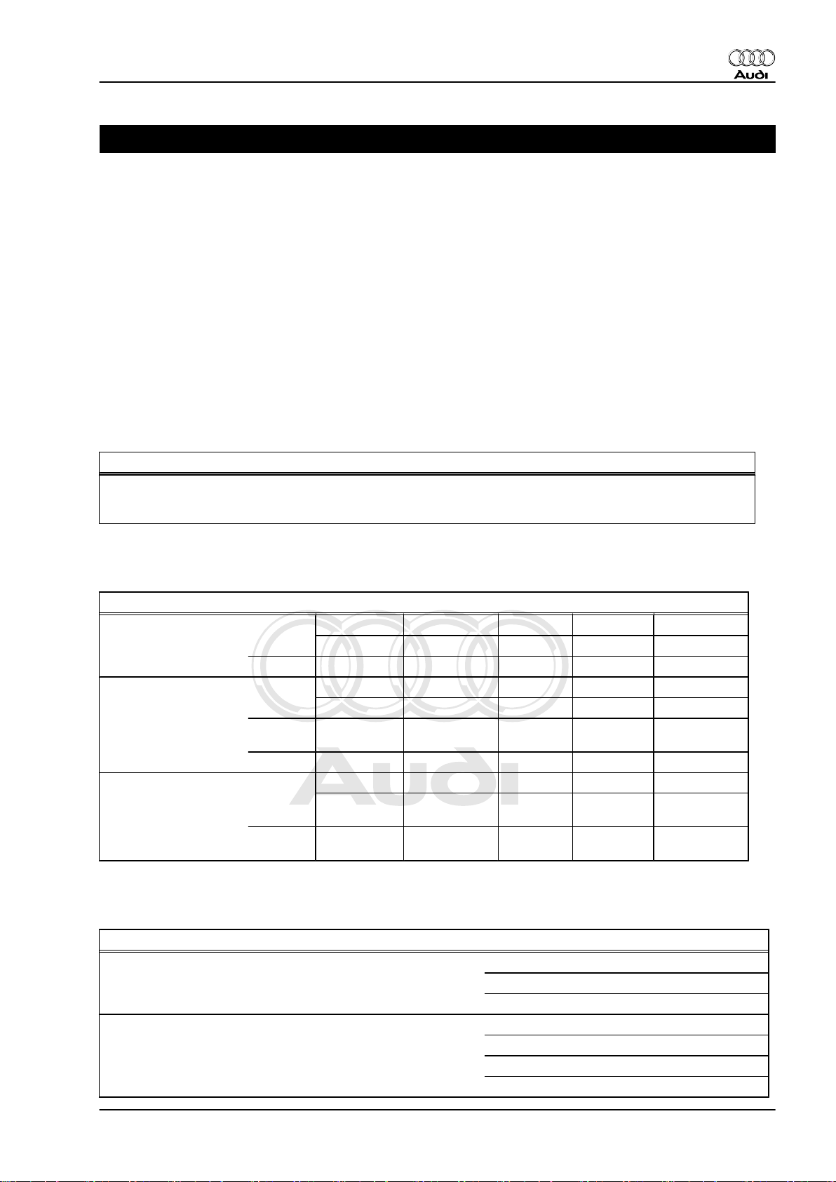
1.3 Front brakes
Front axle
Brake caliper (PR No.)
Front brake caliper
Piston
Brake disc (PR No.)
Front brake disc ∅ mm
Brake disc thickness
(ventilated)
Brake disc, wear limit
Brake pad
Pad thickness (new,
without backplate)
Pad wear limit (without
backplate)
1LJ 1LL 1LK 1LM 1LN
FN3 FN3 FNR-G-57 FNR-G-57 FNR-G-57
∅ mm 54 54 57 57 57
1LJ 1LJ 1LK 1LK 1LK
312 (16“) 312 (16“) 340 (17“) 340 (17“) 340 (17“)
mm 25 25 30 30 30
mm 21 21 27 27 27
mm
mm 2 2 2 2 2
14 14 14 14 14
1.4 Front brakes (TT RS)
Front axle, TT RS
Brakes (PR No.) 1LA
Front brake caliper
Piston
Brake disc (PR No.) 1LK
Front brake disc
Brake disc thickness (ventilated)
Brake disc, wear limit
Brembo (M4)
∅ 40 / 44 mm
∅ 370 mm
32 mm
30 mm
1. Technical data 1
Page 8
Protected by copyright. Copying for private or commercial purposes, in part or in whole, is not
permitted unless authorised by AUDI AG. AUDI AG does not guarantee or accept any liability
with respect to the correctness of information in this document. Copyright by AUDI AG.
Audi TT 2007 ➤
Brake system - Edition 04.2009
Front axle, TT RS
Pad wear limit (without backplate) 2 mm
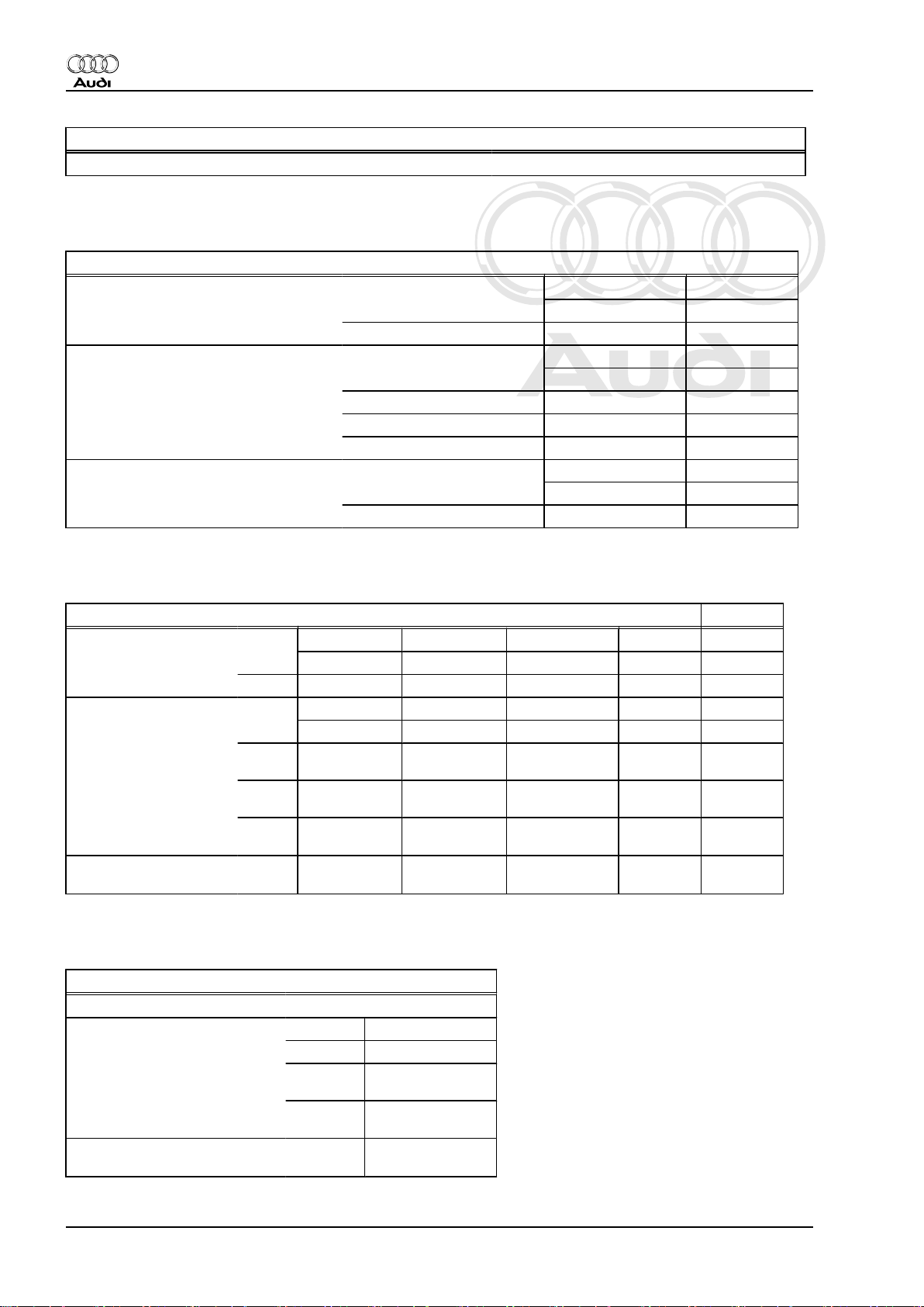
1.5 Rear wheel brakes, front-wheel drive
Rear wheel brakes, front-wheel drive
Brake caliper (PR No.)
Rear brake caliper
Piston
Brake disc (PR No.)
Rear brake disc ∅ mm
Brake disc thickness (non-ventilated)
Brake disc thickness (ventilated)
Brake disc wear limit
Brake pad
Pad thickness (new, without backplate) mm
Pad wear limit (without backplate)
∅ mm 38 38
mm 12 12
mm ------ -----mm 9 9
mm 2 2
2ED 1KZ
CII 38HR CII 38HR
2ED, 2EE 1KZ, 1KJ,
286 (16“) 286 (16“)
12 12
1.6 Rear wheel brakes, four-wheel drive
Rear wheel brakes, four-wheel drive
Brake caliper (PR No.)
Rear brake caliper
Piston
Brake disc (PR No.)
Rear brake disc ∅ mm
Brake disc thickness
(non-ventilated)
Brake disc thickness
(ventilated)
Brake disc,
wear limit
Pad wear limit (without
backplate)
∅ mm 41 41 41 41 41
mm 12 12 ------ ------ ------
mm ------ ------ 22 22 22
mm 9 9 19 19 19
mm 2 2 2 2 2
1KJ 2EE 2EA 2EF 2EG
CII 41HR CII 41HR CII 41HR CII 41HR CII 41HR
1KJ, 1KZ 2EE, 2ED 2EA 2EF 2EG
286 (16“) 286 (16“) 310 (17“) 310 (17“) 310 (17“)
1.7 Rear brakes (TT RS)
Rear brakes (TT RS)
Rear brake caliper CII 41 HR
Piston ∅ mm 41
Rear brake disc
Brake disc thickness (ventilated
brake disc)
Brake disc,
wear limit
Pad wear limit (without back‐
plate)
∅ mm 312
mm 22
mm 19
mm 2
2 Rep. Gr.00 - Technical data
Page 9
Protected by copyright. Copying for private or commercial purposes, in part or in whole, is not
permitted unless authorised by AUDI AG. AUDI AG does not guarantee or accept any liability
with respect to the correctness of information in this document. Copyright by AUDI AG.
2 Brake test
2.1 General notes
The wheels are driven by the test rollers.
During the test the gearbox must be in neutral on manual gear‐
boxes or
in position N on automatic gearboxes.
Follow the instructions provided by the manufacturer of the brake
test equipment when performing the test.
Note
Electronic brake control systems are inoperative when the ignition
is switched off.
2.2 Vehicles with front-wheel drive
Audi TT 2007 ➤
Brake system - Edition 04.2009
Testing on a single-axle brake dynamometer
Perform brake test on a single-axle brake dynamometer.
The EDL control can activate the brakes if the rollers start at dif‐
ferent points in time.
Test speed must not exceed 6 km/h.
All brake test equipment approved by Audi meets these require‐
ments.
2.3 Four-wheel drive vehicles with Haldex coupling
Testing on a single-axle brake dynamometer for four-wheel drive
vehicles
The rollers drive the wheels of one axle in opposite directions to
avoid transmitting torque to the other axle.
The EDL control can activate the brakes if the rollers start at dif‐
ferent points in time.
Test speed must not exceed 6 km/h.
All brake test equipment approved by Audi meets these require‐
ments.
2.4 Testing four-wheel drive vehicles with Haldex coupling on a conventional brake dynamometer
Proceed as follows to test brakes on a conventional brake dyna‐
mometer.
– Drive vehicle forward until front wheels are standing on rollers.
– Switch off engine and wait for 3 seconds.
– Perform brake test on front wheels.
– Allow engine to run for approx. 5 seconds after performing
brake test to build up sufficient vacuum in the servo.
– Drive vehicle forward until rear wheels are standing on rollers.
2. Brake test 3
Page 10
Protected by copyright. Copying for private or commercial purposes, in part or in whole, is not
permitted unless authorised by AUDI AG. AUDI AG does not guarantee or accept any liability
with respect to the correctness of information in this document. Copyright by AUDI AG.
Audi TT 2007 ➤
Brake system - Edition 04.2009
– Switch off engine and wait for 3 seconds.
– Perform brake test on rear wheels.
WARNING
The engine must not run and the ignition must be switched off
during the brake test, otherwise the rear wheels will be driven
by the Haldex coupling.
4 Rep. Gr.00 - Technical data
Page 11
Protected by copyright. Copying for private or commercial purposes, in part or in whole, is not
permitted unless authorised by AUDI AG. AUDI AG does not guarantee or accept any liability
with respect to the correctness of information in this document. Copyright by AUDI AG.
3 Brake fluid
3.1 General notes
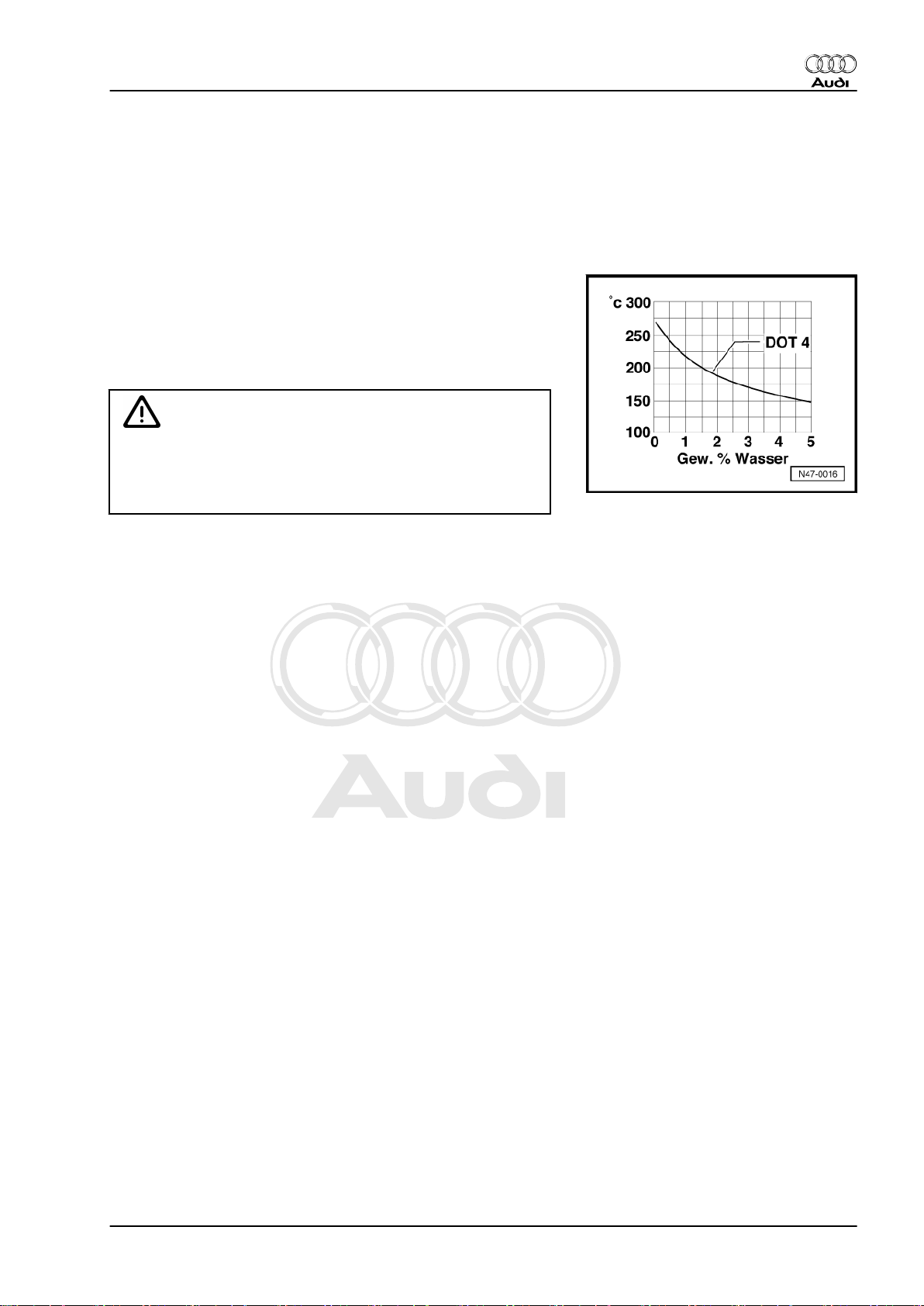
Brake fluid is hygroscopic, i.e. it has the tendency to absorb water
and moisture from the atmosphere
The boiling point decreases as the water content increases, which
means a considerable rise in brake fluid temperature can lead to
formation of vapour bubbles and reduced braking effect.
The colour of the brake fluid becomes darker over the course of
time. This is caused by a normal chemical reaction and is not an
indication of the condition of the fluid.
WARNING
Rubber parts of brake system (sleeves, seals) are not com‐
patible with mineral oil, fuel and cleaning agents. Even minute
quantities coming into contact with a sleeve or seal will affect
the component and could impair brake operation.
Audi TT 2007 ➤
Brake system - Edition 04.2009
3. Brake fluid 5
Page 12
Protected by copyright. Copying for private or commercial purposes, in part or in whole, is not
permitted unless authorised by AUDI AG. AUDI AG does not guarantee or accept any liability
with respect to the correctness of information in this document. Copyright by AUDI AG.
Audi TT 2007 ➤
Brake system - Edition 04.2009
45 – Anti-lock brake system
1 General information on the anti-lock
brake system
1.1 Notes for repair work on ABS Mark 60
WARNING
The anti-lock brake system is basically maintenance-free.
Testing, removing, installing and repair work may only be per‐
formed by qualified personnel.
Failure to observe the information described in this Workshop
Manual may result in damage to the system and could make
the vehicle unsafe.
Note
Malfunctions in the ABS system do not influence the brake system
itself. However, a change in braking behaviour must be reckoned
with.
Vehicles equipped with the ABS Mark 60 do not have a mechan‐
ical brake pressure regulator. A specially matched software in the
control unit controls the rear axle brake pressure regulation.
♦ Before carrying out repair work on the anti-lock brake system,
determine the cause of the problem using self-diagnosis.
♦ Always switch off ignition before unplugging the connector at
hydraulic control unit.
♦ If a new hydraulic control unit has been fitted, it must be en‐
coded. Vehicle diagnostic, testing and information system VAS 505x-
♦ Bleed brake system after performing work involving opening
of brake system: ABS/ESP Mark 60 ⇒ page 109 . To do so,
use for example the brake filling and bleeding equipment V.A.G 1869- or brake filling and bleeding equipment -VAS
5234- .
♦ Absolute cleanliness is required when working on the anti-lock
brake system; avoid any products that contain mineral oil,
such as oil, grease, etc.
♦ Thoroughly clean all connections and the adjacent areas be‐
fore loosening; do not use harsh cleaning agents such as
brake cleaner, fuel, thinners or similar.
♦ Place removed parts on a clean surface and cover them up.
♦ Carefully cover or seal open components if repairs are not to
be carried out immediately. Use plugs from repair kit; Part No.
⇒ ETKA .
♦ When the brake system is open do not work with compressed
air and do not move the vehicle.
♦ Only use lint-free cloths.
♦ Only use genuine spare parts from original packaging.
6 Rep. Gr.45 - Anti-lock brake system
Page 13

Protected by copyright. Copying for private or commercial purposes, in part or in whole, is not
permitted unless authorised by AUDI AG. AUDI AG does not guarantee or accept any liability
with respect to the correctness of information in this document. Copyright by AUDI AG.
♦ Only remove replacement parts from packaging immediately
prior to installation.
♦ During the final road test, ensure that at least one ABS-con‐
trolled braking operation is performed (pulsations must be felt
at the brake pedal).
♦ During painting operations, the electronic control unit can be
exposed to a maximum temperature of 95 °C for only a short
period, and to a maximum of 85 °C for longer periods (approx.
2 hours).
♦ Before carrying out welding work with an electric welding unit,
refer to ⇒ General notes; Body repairs; Safety notes .
Audi TT 2007 ➤
Brake system - Edition 04.2009
1. General information on the anti-lock brake system 7
Page 14
Protected by copyright. Copying for private or commercial purposes, in part or in whole, is not
permitted unless authorised by AUDI AG. AUDI AG does not guarantee or accept any liability
with respect to the correctness of information in this document. Copyright by AUDI AG.
Audi TT 2007 ➤
Brake system - Edition 04.2009
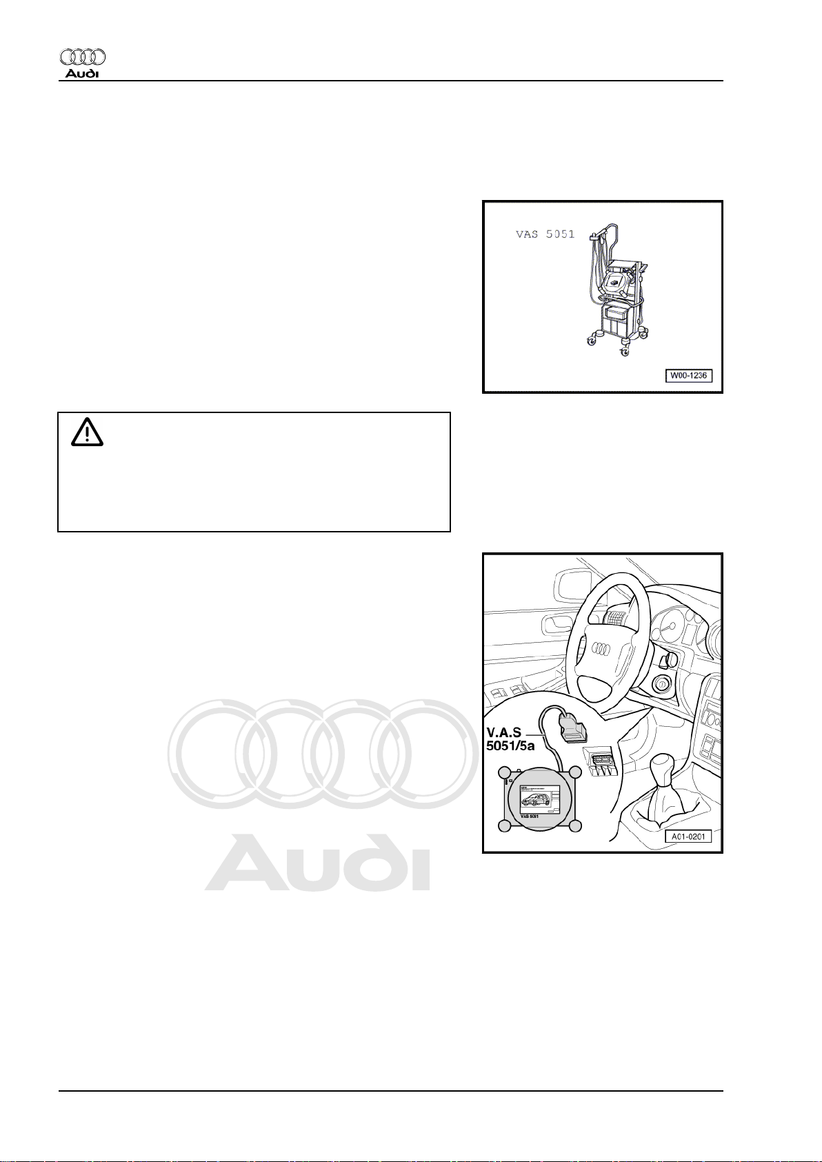
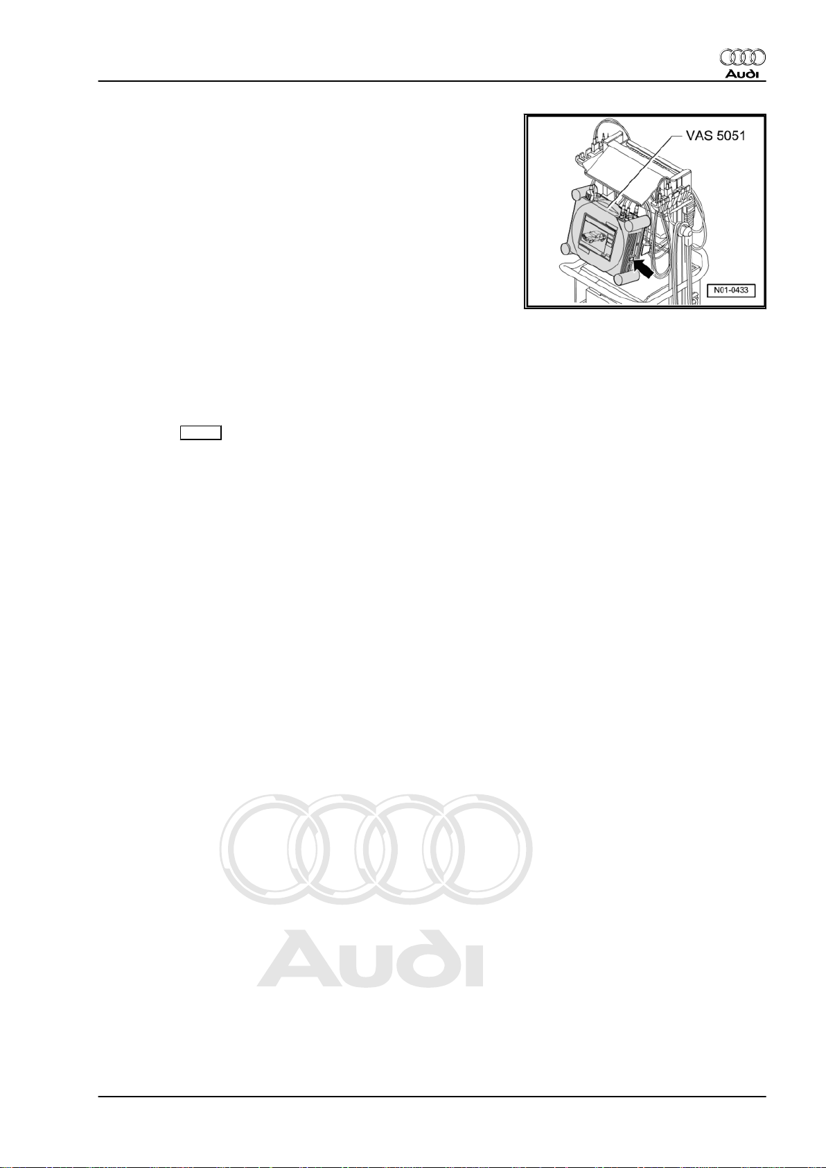
2 Connecting -VAS 505x- and select‐
ing functions
Special tools and workshop equipment required
♦ Vehicle diagnostic, testing and information system -VAS 505x-
WARNING
♦ Test equipment must always be secured to the rear seat
when road-testing the vehicle.
♦ While the vehicle is moving this equipment must be oper‐
ated by a second person; NOT by the driver.
– Attach the diagnosis cable connector to the diagnosis con‐
nection.
8 Rep. Gr.45 - Anti-lock brake system
Page 15
Protected by copyright. Copying for private or commercial purposes, in part or in whole, is not
permitted unless authorised by AUDI AG. AUDI AG does not guarantee or accept any liability
with respect to the correctness of information in this document. Copyright by AUDI AG.
– Switch on tester -arrow-.
The tester is ready as soon as a picture of a car appears in the
display.
– Switch on ignition.
– Press the Guided Fault Finding button on the display screen.
– Select the following:
♦ Make
♦ Model
♦ Model year
♦ Version
♦ Engine code letters
– Confirm the entered information.
Wait until the tester has interrogated all the control units in the
vehicle.
– Press the Go to button and select the option “Function/com‐
ponent selection”.
Follow the instructions in the display to begin with the desired
functions.
Audi TT 2007 ➤
Brake system - Edition 04.2009
2. Connecting VAS 505x and selecting functions 9
Page 16
Protected by copyright. Copying for private or commercial purposes, in part or in whole, is not
permitted unless authorised by AUDI AG. AUDI AG does not guarantee or accept any liability
with respect to the correctness of information in this document. Copyright by AUDI AG.
Audi TT 2007 ➤
Brake system - Edition 04.2009
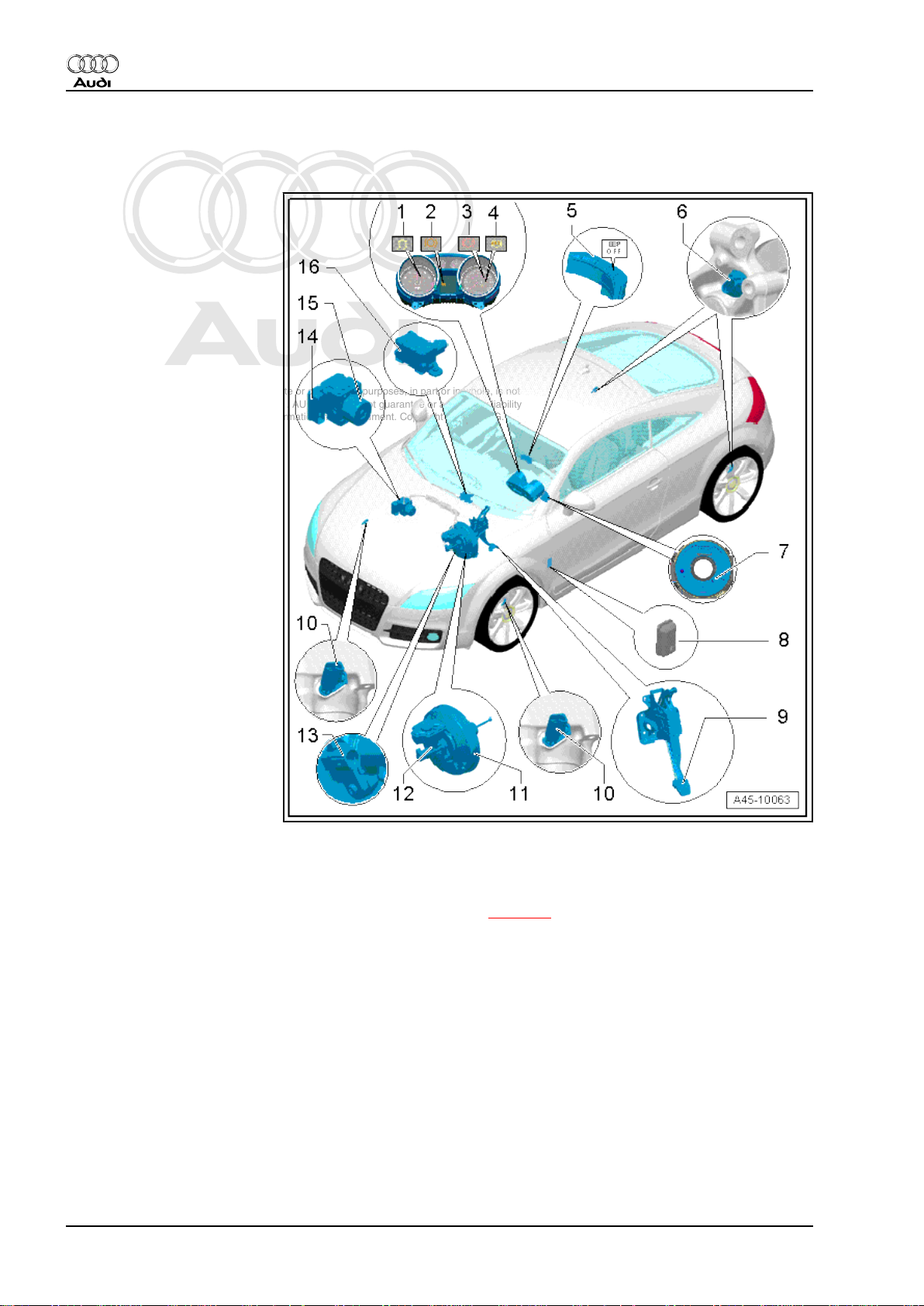
3 Components and fitting locations on brake system ABS/ESP Mark 60
1 - ESP and TCS warning lamp
-K155❑ Fitting location: in rev.
counter.
❑ Flashes when the vehi‐
cle is in motion and the
ESP/TCS control is in
operation
❑ Lights up when the igni‐
tion is switched on and
goes out after a short
self-test has been com‐
pleted
❑ Lights up if there is a
malfunction in the ESP
❑ Lights up if there is a
malfunction in the ABS,
since the ESP works in
conjunction with the
ABS
❑ Lights up when the ESP
is switched off
❑ Lights up during auto‐
matic self-adaption of
the sensor systems
when:
♦ the battery has been dis‐
connected and then re-con‐
nected
♦ the vehicle has been jump-
started
♦ the battery charge level is
very low
❑ The warning lamp goes
out after the vehicle has
been in motion for a
short time as soon as the learning procedure of the sensor systems is finalised.
2 - Brake pad warning lamp -K32-
❑ Fitting location: in centre display zone
❑ Lights up when wear limit of the brake pads is reached ⇒ page 1
3 - Brake system warning lamp -K118-
❑ Fitting location: in speedometer
❑ Lights up when the handbrake is applied.
❑ Lights up if there is a malfunction in the ABS system.
❑ Flashes if brake fluid level is too low
4 - ABS warning lamp -K47-
❑ Fitting location: in speedometer
❑ Lights up for a few seconds when the ignition is switched on and goes out after the automatic ABS self-
test has been completed, providing no faults have been detected in the ABS.
❑ There is a malfunction of the ABS if the warning lamp:
♦ does not light up when the ignition is switched on,
♦ does not go out again after a few seconds,
10 Rep. Gr.45 - Anti-lock brake system
Page 17
Protected by copyright. Copying for private or commercial purposes, in part or in whole, is not
permitted unless authorised by AUDI AG. AUDI AG does not guarantee or accept any liability
with respect to the correctness of information in this document. Copyright by AUDI AG.
Audi TT 2007 ➤
Brake system - Edition 04.2009
♦ lights up while the vehicle is in motion.
❑ Malfunctions in the ABS system do not influence the brake system itself. However, a change in braking
behaviour must be reckoned with.
❑ The ESP warning lamp will light up as well as the ABS warning lamp if there is a malfunction in the ABS,
since the two systems work in conjunction.
5 - TCS and ESP button -E256-
❑ Fitting location: on the centre console
6 - Rear left speed sensor -G44- , rear right speed sensor -G46- -
❑ 8 Nm
7 - Steering angle sender -G85-
❑ Fitting location: on steering column between steering wheel and steering column switch
❑ Removing and installing ⇒ page 16
8 - Diagnostic connection
❑ Fitting location: cover in driver's footwell
9 - Brake pedal
❑ Removing and installing ⇒ page 91
10 - Front left speed sensor -G45- , front right speed sensor -G47-
❑ Removing and installing ⇒ page 40
❑ 8 Nm
11 - Brake servo
❑ Removing and installing ⇒ page 113
Note
♦
On vehicles with TTS engine the
noise amplifier must be removed
and installed ⇒ page 129 .
♦
The noise amplifier is located in
the engine compartment in front
of the brake servo.
❑ With integrated brake vacuum sender -G 483
❑ Brake vacuum sender -G 483 is not fitted on all models
❑ Removing and installing brake servo vacuum sender -G 483 ⇒ page 17
Note
The brake vacuum sender -G 483 is
only installed on vehicles with
OHBV.
12 - Brake master cylinder
❑ With brake light switch attached
❑ Removing and installing ⇒ page 117
Note
♦
On vehicles with TTS engine the
noise amplifier must be removed
and installed ⇒ page 129 .
♦
The noise amplifier is located in
the engine compartment in front
of the brake servo.
3. Components and fitting locations on brake system ABS/ESP Mark 60 11
Page 18
Protected by copyright. Copying for private or commercial purposes, in part or in whole, is not
permitted unless authorised by AUDI AG. AUDI AG does not guarantee or accept any liability
with respect to the correctness of information in this document. Copyright by AUDI AG.
Audi TT 2007 ➤
Brake system - Edition 04.2009
13 - Brake light switch
❑ Removing and installing ⇒ page 13
❑ Removing and installing (TT RS) ⇒ page 13
❑ The brake light switch is not adjustable.
❑ Location: On brake master cylinder
❑ 5 Nm
14 - ABS control unit (with ESP) -J104-
❑ Fitting location: on hydraulic unit -N55 on right-side of engine compartment.
❑ Do not unplug connector before completing self-diagnosis. Switch off ignition before detaching connector.
❑ Removing and installing ⇒ page 20
❑ Removing and installing (TFSI engine) ⇒ page 25
❑ Removing and installing (vehicles with diesel particulate filter) ⇒ page 34
Caution
ABS control unit -J104and ABS hydraulic unit N55- must not be sepa‐
rated.
15 - ABS hydraulic unit -N55-
❑ Fitting location: in engine compartment (right-side) on control unit -J104-.
❑ Removing and installing ⇒ page 20
❑ Removing and installing (TFSI engine) ⇒ page 25
❑ Removing and installing (vehicles with diesel particulate filter) ⇒ page 34
❑ The ABS hydraulic pump -V64- , the ABS hydraulic unit -N55- and the ABS control unit (with ESP) -J104-
together make up the hydraulic control unit.
❑ With integrated brake pressure sender -G201❑ The brake pressure sender -G201- cannot be renewed separately.
❑ Allocation ⇒ ETKA
16 - ESP sensor unit -G419-
❑ 9 Nm
❑ Fitting location: on centre console in front of gear lever.
❑ Combined lateral acceleration sender -G200- and yaw rate sender -G202❑ Longitudinal acceleration sender -G251- (only four-wheel drive vehicles)
❑ Removing and installing ESP sensor unit ⇒ page 15
Note
The ABS sensor ring / rotor is incorporated in the corresponding
wheel bearing unit and cannot be renewed.
12 Rep. Gr.45 - Anti-lock brake system
Page 19
Protected by copyright. Copying for private or commercial purposes, in part or in whole, is not
permitted unless authorised by AUDI AG. AUDI AG does not guarantee or accept any liability
with respect to the correctness of information in this document. Copyright by AUDI AG.
4 Removing and installing parts of
ABS/ESP system
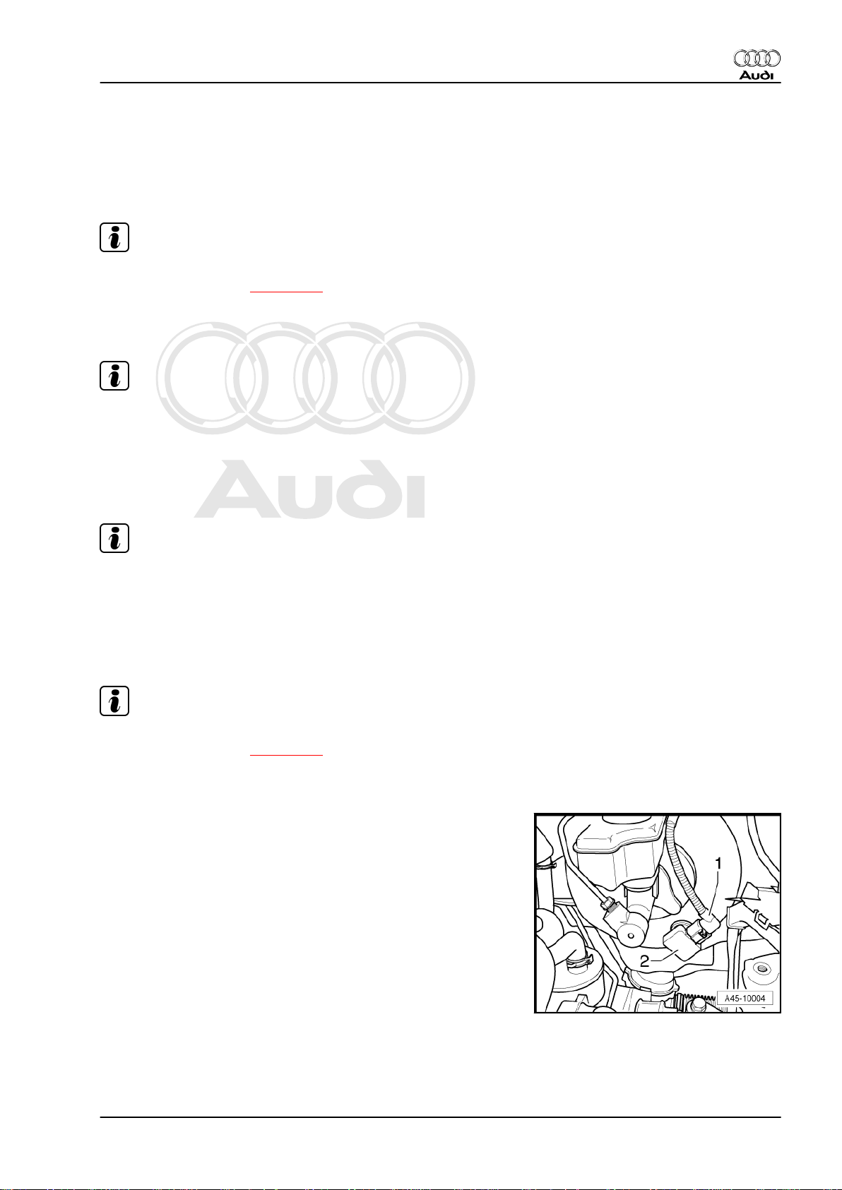
4.1 Removing and installing brake light switch
Removing
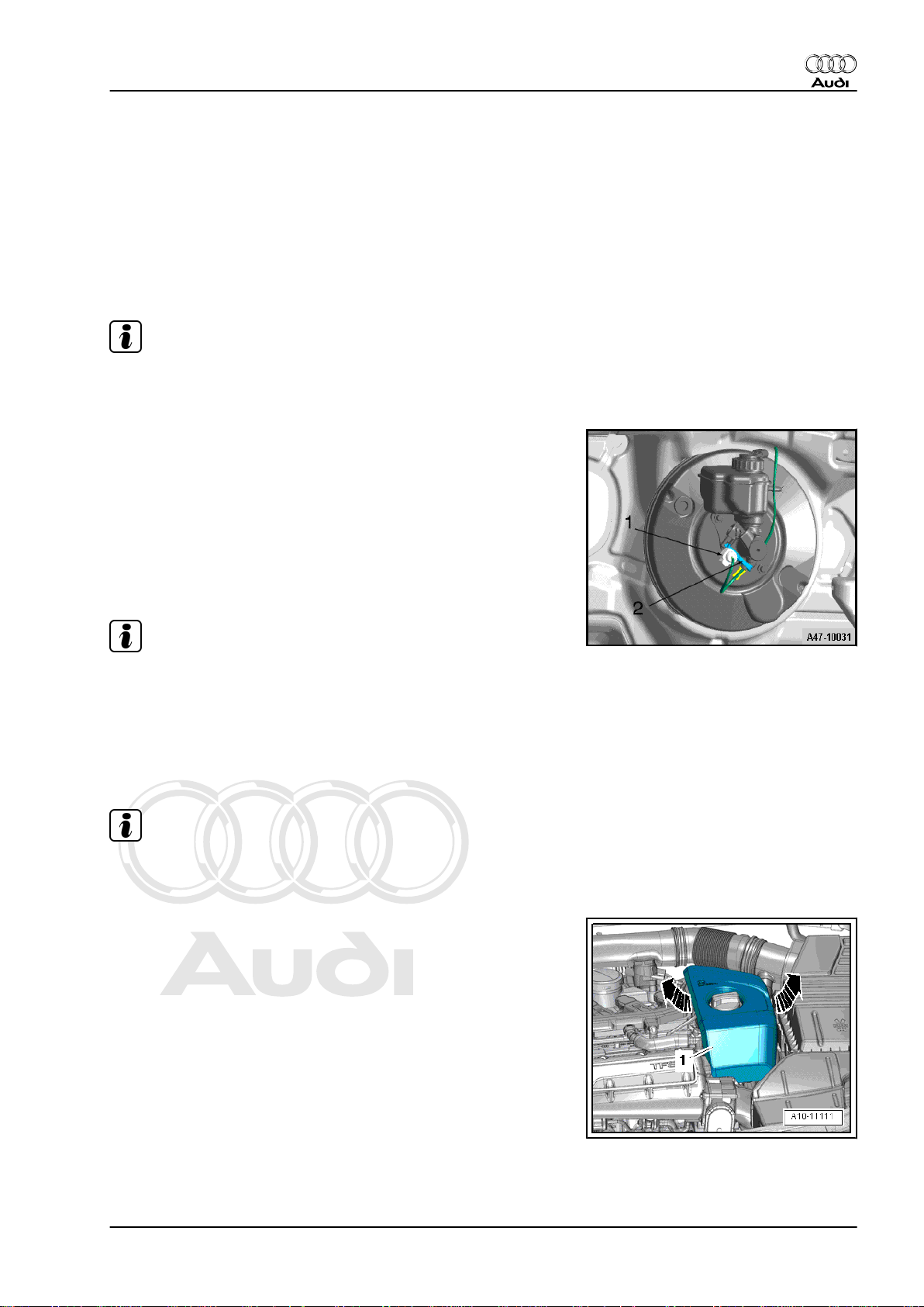
Note
♦
The brake light switch is located on the brake master cylinder.
♦
The brake light switch is not adjustable.
– Unplug electrical connector -1-.
– Remove securing bolt for brake light switch -2- from brake
master cylinder.
– Pull brake light switch at bottom out of brake master cylinder
and lift switch out of retaining tab at top.
Installing
– Installation is carried out in the reverse sequence. Ensure
proper seating of switch in retaining tab at top.
Audi TT 2007 ➤
Brake system - Edition 04.2009
Note
The brake light switch is not adjustable.
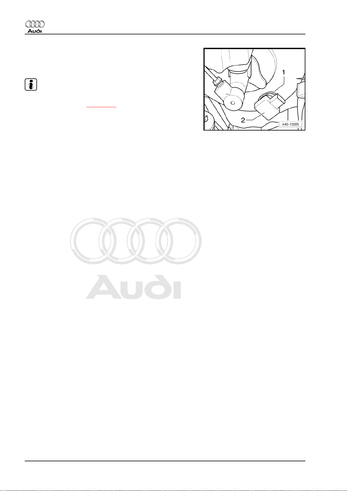
4.2 Removing and installing brake light switch (TT RS)
Removing
Note
♦
The brake light switch is located on the brake master cylinder.
♦
The brake light switch is not adjustable.
– Lift off engine cover panel -1-.
4. Removing and installing parts of ABS/ESP system 13
Page 20
Protected by copyright. Copying for private or commercial purposes, in part or in whole, is not
permitted unless authorised by AUDI AG. AUDI AG does not guarantee or accept any liability
with respect to the correctness of information in this document. Copyright by AUDI AG.
Audi TT 2007 ➤
Brake system - Edition 04.2009
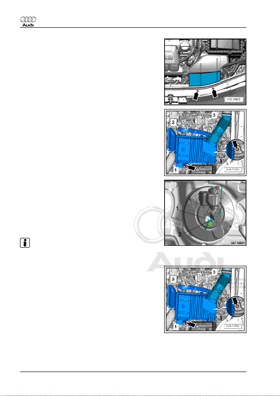
– Unscrew bolts -arrows- and detach air duct.
– Unscrew bolts -arrows- and detach air cleaner housing.
– Unplug electrical connector -1-.
– Remove securing bolt for brake light switch -2- from brake
master cylinder.
– Pull brake light switch at bottom out of brake master cylinder
and lift switch out of retaining tab at top.
Installing
– Installation is carried out in the reverse sequence. Ensure
proper seating of switch in retaining tab at top.
Note
The brake light switch is not adjustable.
– Insert air cleaner housing and tighten bolts -arrows-.
14 Rep. Gr.45 - Anti-lock brake system
Page 21
Protected by copyright. Copying for private or commercial purposes, in part or in whole, is not
permitted unless authorised by AUDI AG. AUDI AG does not guarantee or accept any liability
with respect to the correctness of information in this document. Copyright by AUDI AG.
– Insert air duct and tighten bolts -arrows-.
– Install engine cover panel.
4.3 Removing and installing ESP sensor unit -G419-
WARNING
The ESP sensor unit is sensitive to impact. The ESP sensor
unit can be damaged if subjected to impact. If the ESP sensor
unit has been dropped by mistake it may not work properly and
must not be installed in the vehicle.
Audi TT 2007 ➤
Brake system - Edition 04.2009
– After renewing ESP sensor unit -G419-, a basic setting (cali‐
bration) for
♦ Lateral acceleration sender -G200-
♦ Yaw rate sender -G202-
♦ Longitudinal acceleration sender -G251- (on four-wheel drive
vehicles)
– must be performed
Removing
Note
ESP sensor unit -G419 is fitted on centre console under trim in
front of gear lever / selector lever.
– Remove centre console trim ⇒ Rep. Gr. 68 .
– Unplug connector.
– Remove bolts.
– Lift out ESP sensor unit -G419-.
Installing
Installation is performed in reverse sequence; note the following:
Calibrate lateral acceleration sender -G200 and longitudinal ac‐
celeration sender -G251 on vehicles with four-wheel drive. To do
so, use the vehicle diagnosis, testing and information system VAS 505x- .
– Select on the display:
♦ Running gear
♦ Brake system (Repair group 01; 45)
♦ 01 - Self-diagnosis compatible systems
4. Removing and installing parts of ABS/ESP system 15
Page 22
Protected by copyright. Copying for private or commercial purposes, in part or in whole, is not
permitted unless authorised by AUDI AG. AUDI AG does not guarantee or accept any liability
with respect to the correctness of information in this document. Copyright by AUDI AG.
Audi TT 2007 ➤
Brake system - Edition 04.2009
♦ 03 - Brake electronics ABS/ESP Mark 60
– Select the function you require on the display.
♦ Calibrate lateral acceleration sender -G200-
♦ Calibrate longitudinal acceleration sender -G251- (only on
four-wheel drive vehicles)
– Carry out ESP road test and system test.
4.4 Removing and installing steering angle sender -G85-
Removing
– Turn wheels to straight ahead position.
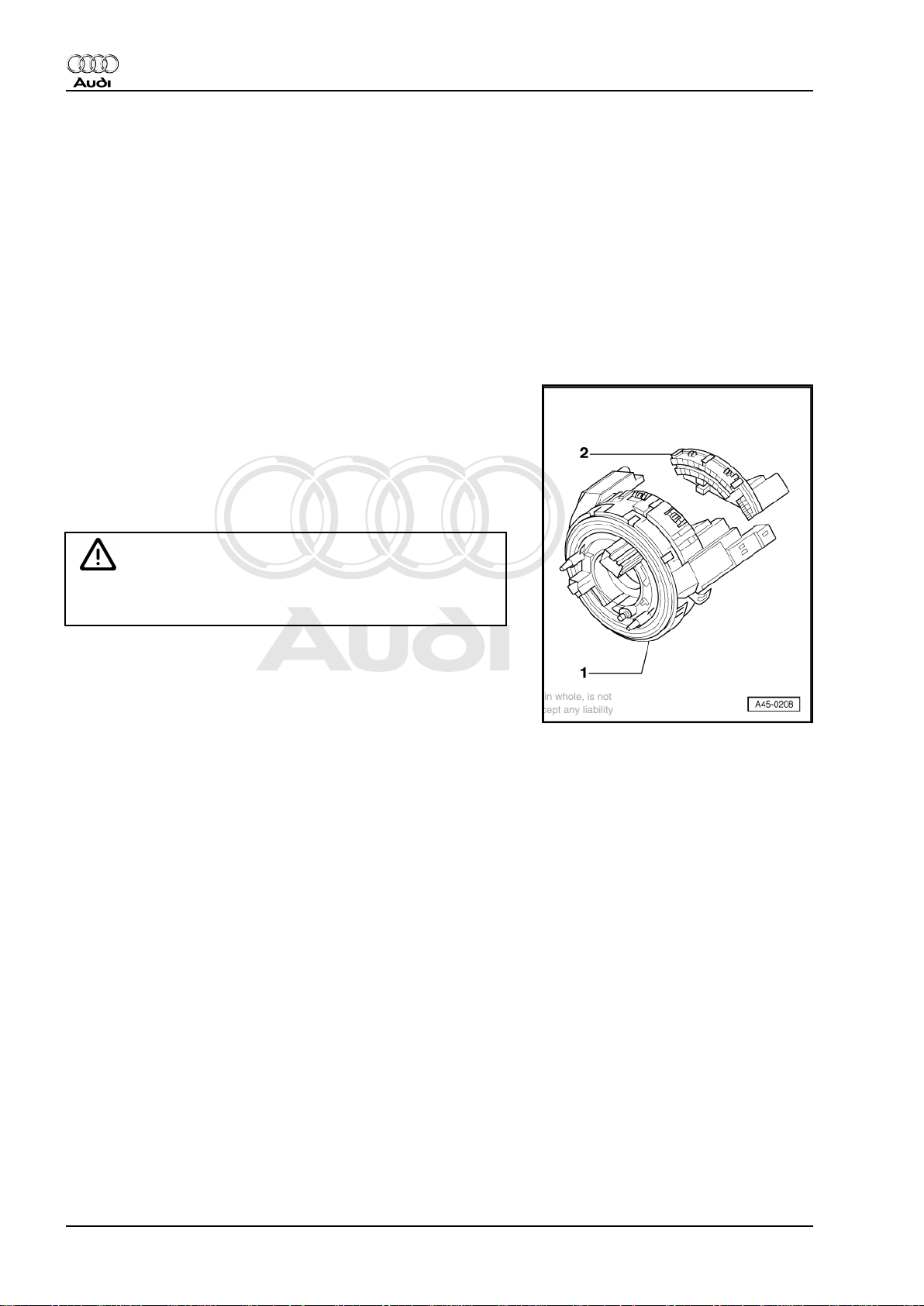
– Remove airbag unit and steering wheel ⇒ Rep. Gr. 48 .
Item -1-: Return ring with slip ring
- Clipped to switch for turn signal indicator, main beam, dipped
beam and headlight flasher
Item -2- Steering angle sender -G85-
- Clipped to return ring with slip ring
WARNING
The return ring with slip ring must not be rotated following re‐
moval.
– Remove driver's storage compartment ⇒ Rep. Gr. 68 .
– Remove steering column switch module ⇒ Rep. Gr. 94 .
Installing
Installation is carried out in the reverse sequence.
– Install airbag unit and steering wheel. ⇒ Rep. Gr. 48
Calibrate steering angle sender -G85.
To do this, use vehicle diagnosis, testing and information system
-VAS 505x- .
– Select on the display:
♦ Running gear
♦ Brake system (Repair group 01; 45)
♦ 01 - Self-diagnosis compatible systems
♦ 03 - Brake electronics ABS/ESP Mark 60
– Select the function you require on the display.
♦ J104 - Control unit for ABS/TCS/ESP, Functions
♦ G-85 - Calibrate steering angle sensor ⇒ Vehicle diagnosis,
testing and information system -VAS 505x- .
– Carry out ESP road test and system test.
16 Rep. Gr.45 - Anti-lock brake system
Page 23
Protected by copyright. Copying for private or commercial purposes, in part or in whole, is not
permitted unless authorised by AUDI AG. AUDI AG does not guarantee or accept any liability
with respect to the correctness of information in this document. Copyright by AUDI AG.
4.5 Removing and installing brake servo
vacuum sender -G483- . Only on vehi‐
cles with (OHBV) optimised hydraulic
brake assistance/vacuum sender
Note
♦
On vehicles with TTS engine the noise amplifier must be re‐
moved and installed ⇒ page 129 .
♦
The noise amplifier is located in the engine compartment in
front of the brake servo.
Note
Vehicles on which the brake vacuum is supplied entirely by the
intake manifold and vehicles with mechanical vacuum pump are
not fitted with brake servo vacuum sender -G483.
Audi TT 2007 ➤
Brake system - Edition 04.2009
Special tools and workshop equipment required
♦ Vehicle diagnostic, testing and information system -VAS 505x-
Note
♦
Brake servo vacuum sender -G483- does not have to be cali‐
brated after renewal.
♦
The "Guided Fault Finding" contains a description of the elec‐
trical check.
Removing
Note
♦
On vehicles with TTS engine the noise amplifier must be re‐
moved and installed ⇒ page 129 .
♦
The noise amplifier is located in the engine compartment in
front of the brake servo.
– Unplug electrical connector -1- for vacuum sender -2-.
4. Removing and installing parts of ABS/ESP system 17
Page 24
Protected by copyright. Copying for private or commercial purposes, in part or in whole, is not
permitted unless authorised by AUDI AG. AUDI AG does not guarantee or accept any liability
with respect to the correctness of information in this document. Copyright by AUDI AG.
Audi TT 2007 ➤
Brake system - Edition 04.2009
– Pull back retaining ring -1- on OHBV and remove sender -
G483 -2- from brake servo.
Installing
Note
♦
On vehicles with TTS engine the noise amplifier must be re‐
moved and installed ⇒ page 129 .
♦
The noise amplifier is located in the engine compartment in
front of the brake servo.
Installation is carried out in reverse sequence.
18 Rep. Gr.45 - Anti-lock brake system
Page 25
Protected by copyright. Copying for private or commercial purposes, in part or in whole, is not
permitted unless authorised by AUDI AG. AUDI AG does not guarantee or accept any liability
with respect to the correctness of information in this document. Copyright by AUDI AG.
Brake system - Edition 04.2009
5 ABS/ESP Mark 60 control unit -J104-
and hydraulic unit -N55-
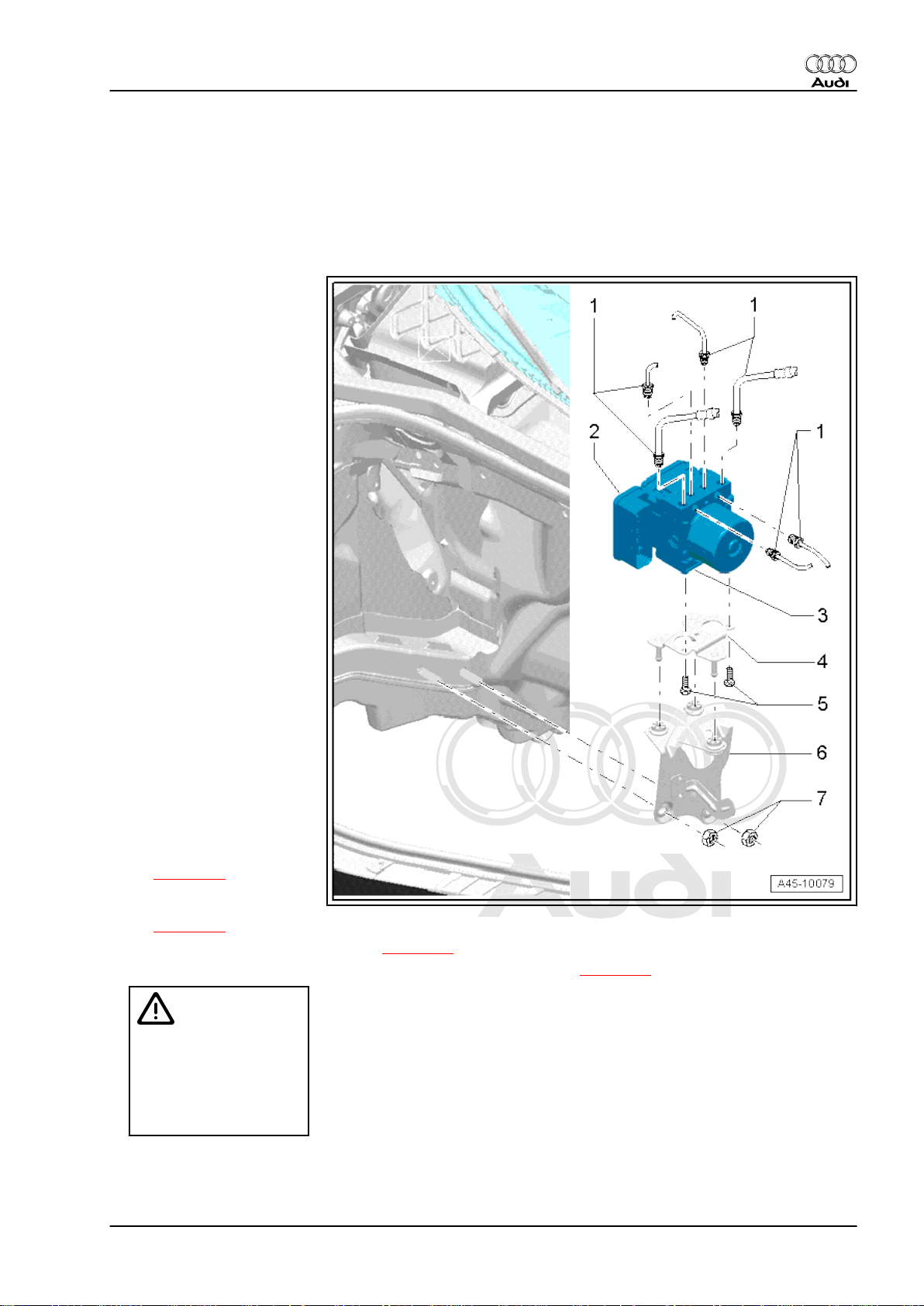
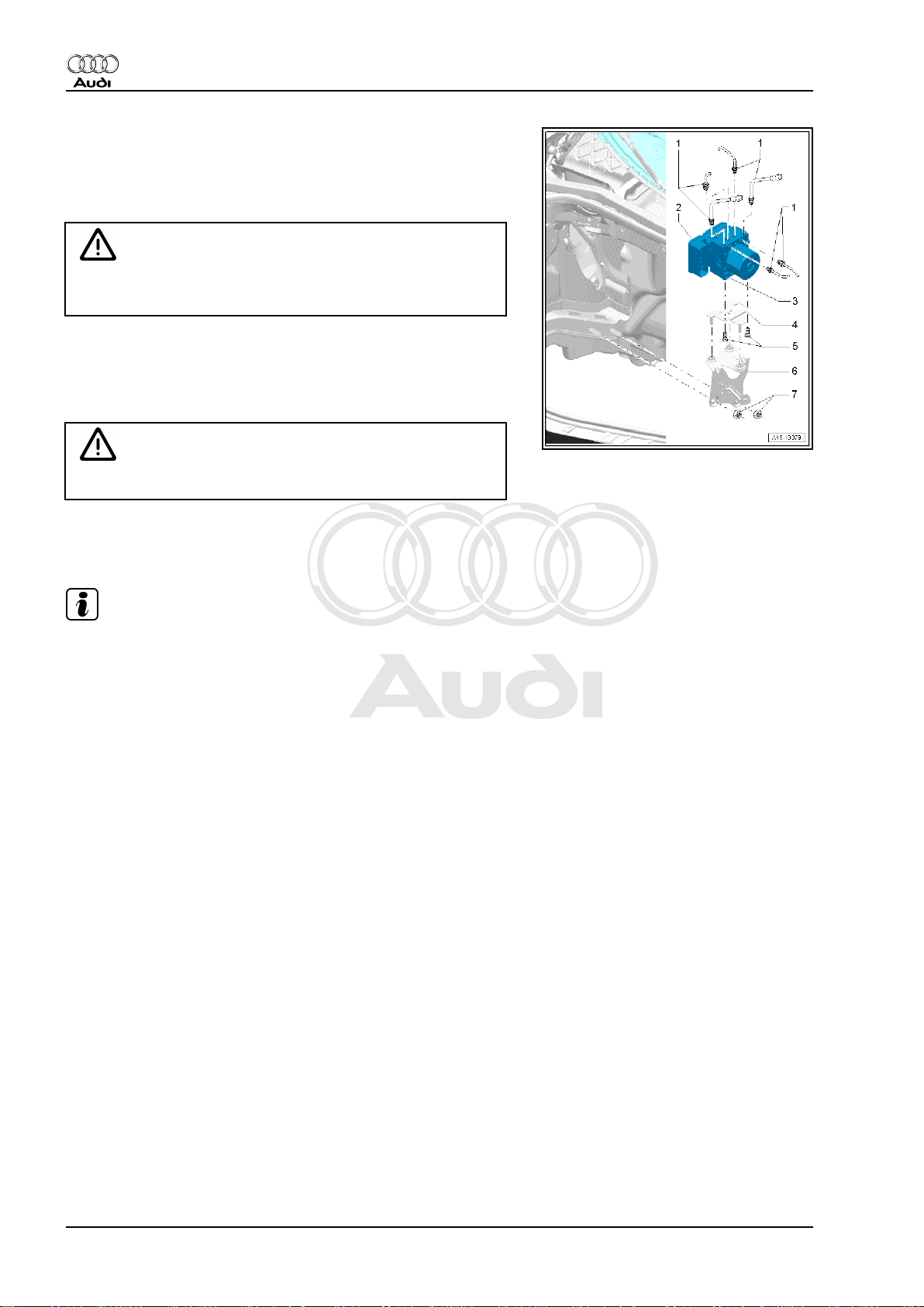
5.1 Exploded view
1 - Brake lines
♦ Marking - DK - Brake mas‐
ter cylinder/primary piston
circuit to hydraulic unit.
♦ Marking - HL - To rear left
brake caliper.
♦ Marking - VR - To front right
brake caliper.
♦ Marking - VL - To front left
brake caliper.
♦ Marking - HR - To rear right
brake caliper.
♦ Marking - SK - Brake mas‐
ter cylinder/secondary pis‐
ton circuit to hydraulic unit.
❑ 14 Nm
❑ Perform final control di‐
agnosis after securing
brake lines to hydraulic
unit. To do this, use ve‐
hicle diagnosis, testing
and information system
-VAS 505x- .
2 - ABS control unit (with ESP)
-J104❑ Fitting location: on hy‐
draulic unit -N55 on
right-side of engine
compartment.
❑ Allocation ⇒ ETKA
❑ Removing and installing
⇒ page 20
❑ Removing and installing
(TFSI engine)
⇒ page 25
❑ Removing and installing (TT RS) ⇒ page 29
❑ Removing and installing (vehicles with diesel particulate filter) ⇒ page 34
Audi TT 2007 ➤
Caution
ABS control unit -J104and ABS hydraulic unit N55- must not be sepa‐
rated. Control unit and
hydraulic unit must be re‐
newed as one unit.
3 - ABS hydraulic unit -N55-
❑ Fitting location: in engine compartment (right-side) on control unit -J104❑ Allocation ⇒ ETKA
5. ABS/ESP Mark 60 control unit -J104- and hydraulic unit -N55- 19
Page 26
Protected by copyright. Copying for private or commercial purposes, in part or in whole, is not
permitted unless authorised by AUDI AG. AUDI AG does not guarantee or accept any liability
with respect to the correctness of information in this document. Copyright by AUDI AG.
Audi TT 2007 ➤
Brake system - Edition 04.2009
❑ Removing and installing ⇒ page 20
❑ Removing and installing (TFSI engine) ⇒ page 25
❑ Removing and installing (TT RS) ⇒ page 29
❑ Removing and installing (vehicles with diesel particulate filter) ⇒ page 34
4 - Bracket
❑ Removing and installing together with hydraulic unit -N55- and control unit -J104- ⇒ page 20
5 - Bolt
❑ Bracket to hydraulic unit
❑ 8 Nm
6 - Mounting bracket
❑ With rubber buffer
7 - Nut
5.2 Removing and installing ABS control unit -J104- and ABS hydraulic unit -N55-
Caution
ABS control unit -J104- and ABS hydraulic unit -N55- must not
be separated.
Removing hydraulic unit with control unit
– Read out control unit version and note down.
– Disconnect battery ⇒ Electrical system; Rep. Gr. 27 (note
radio code).
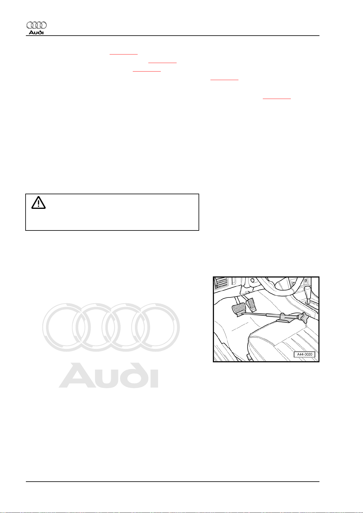
– Insert brake pedal actuator -V.A.G 1869/2- between brake
pedal and driver's seat (depress brake pedal at least 60 mm).
– Connect hose of bleeder bottle to bleeder screws of front left
and rear left brake calipers.
– Open bleeder screws of rear left and front left brake calipers
to release pressure in hydraulic unit.
– Close bleeder screws of front left and rear left brake calipers.
– Do not remove brake pedal actuator -V.A.G 1869/2- .
20 Rep. Gr.45 - Anti-lock brake system
Page 27

Protected by copyright. Copying for private or commercial purposes, in part or in whole, is not
permitted unless authorised by AUDI AG. AUDI AG does not guarantee or accept any liability
with respect to the correctness of information in this document. Copyright by AUDI AG.
– Release connector at control unit -arrow 1- and unplug
-arrow 2-.
Note
♦
Make sure brake fluid does not get into connector housing of
control unit. This can result in corrosion of the contacts and
failure of the system.
♦
Use compressed air to carefully clean connector housing if
necessary.
– To protect against escaping brake fluid, place a sufficient
number of lint-free cloths in area beneath control unit and hy‐
draulic unit.
– Mark brake lines ⇒ Item 1 (page 19) .
WARNING
Do not bend or kink brake lines.
Audi TT 2007 ➤
Brake system - Edition 04.2009
– Unscrew brake lines from hydraulic unit -2- to brake master
cylinder and tie in place.
– Disconnect remaining brake lines -3- on hydraulic unit.
Note
Hydraulic pump -1- must not be separated from hydraulic unit.
– Seal brake lines and threaded holes using sealing plugs from
repair kit.
5. ABS/ESP Mark 60 control unit -J104- and hydraulic unit -N55- 21
Page 28
Protected by copyright. Copying for private or commercial purposes, in part or in whole, is not
permitted unless authorised by AUDI AG. AUDI AG does not guarantee or accept any liability
with respect to the correctness of information in this document. Copyright by AUDI AG.
Audi TT 2007 ➤
Brake system - Edition 04.2009
– Carefully pull hydraulic unit -2- together with control unit and
bracket -4- out of rubber buffers on mounting bracket -6-.
– Take hydraulic unit out of vehicle.
– Unscrew bolts -5- from bracket -4- and detach bracket.
WARNING
Severe shocks or jolts can damage the control unit. The control
unit must not be re-installed if it has been damaged in any way.
– Place hydraulic unit on a clean flat surface with control unit
facing downwards.
Seal threaded holes and brake lines using sealing plugs 1H0.698.311.A after removing control unit and hydraulic unit.
WARNING
Hydraulic pump must not be separated from hydraulic unit.
Installing
Installation is performed in reverse sequence; note the following:
Note
♦
The hydraulic unit supplied as a replacement is filled with
brake fluid.
♦
Do not remove sealing plug of corresponding brake line before
fitting, otherwise brake fluid will escape. Proper bleeding is
then no longer ensured.
22 Rep. Gr.45 - Anti-lock brake system
Page 29

Protected by copyright. Copying for private or commercial purposes, in part or in whole, is not
permitted unless authorised by AUDI AG. AUDI AG does not guarantee or accept any liability
with respect to the correctness of information in this document. Copyright by AUDI AG.
– Secure bracket -4- by tightening bolts -5- to 8 Nm.
– Carefully insert hydraulic unit -2- together with control unit and
bracket -4- in rubber buffers on mounting bracket -6-.
Make sure that rubber buffers are not pressed through mounting
bracket when inserting unit.
– Connect brake lines as previously marked.
WARNING
Interchanging brake line connections will result in ESP system
malfunction.
– Connect brake lines to hydraulic unit.
– Attach connector to control unit and lock connector.
– Bleed brake system ⇒ page 109 .
– Perform final control diagnosis after securing brake lines to
hydraulic unit.
To do this, use vehicle diagnosis, testing and information system
-VAS 505x- .
Audi TT 2007 ➤
Brake system - Edition 04.2009
Note
Final control diagnosis can be used to establish whether line con‐
nections have been interchanged.
If a new ABS control unit -J104- has been fitted, it must be enco‐
ded.
To do this, use vehicle diagnosis, testing and information system
-VAS 505x- .
– Select on the display:
♦ Running gear
♦ Brake system (Repair group 01; 45)
♦ 01 - Self-diagnosis compatible systems
♦ 03 - Brake electronics ABS/ESP Mark 60
– Select required function on the display.
♦ J104 - Control unit for ABS/TCS/ESP Mark 60
♦ J104 - Control unit for ABS/TCS/ESP, Functions
♦ J104 - Encoding control unit
Also calibrate the following senders after renewing control unit J104-.
♦ Steering angle sender -G85-
♦ Lateral acceleration sender -G200-
♦ Brake pressure sender 1 -G201-
♦ Longitudinal acceleration sender -G251- (only on four-wheel
drive vehicles)
To do this, use vehicle diagnosis, testing and information system
-VAS 505x- .
– Select on the display:
5. ABS/ESP Mark 60 control unit -J104- and hydraulic unit -N55- 23
Page 30
Protected by copyright. Copying for private or commercial purposes, in part or in whole, is not
permitted unless authorised by AUDI AG. AUDI AG does not guarantee or accept any liability
with respect to the correctness of information in this document. Copyright by AUDI AG.
Audi TT 2007 ➤
Brake system - Edition 04.2009
♦ Running gear
♦ Brake system
♦ 01 - Self-diagnosis compatible systems
♦ 03 - Brake electronics ABS/ESP Mark 60
– Select required function on the display.
♦ J104 - Control unit for ABS/TCS/ESP Mark 60
♦ J104 - Control unit for ABS/TCS/ESP, Functions
– Then carry out ESP road test and system test.
WARNING
Before driving vehicle for the first time, make sure function of
brakes is OK.
24 Rep. Gr.45 - Anti-lock brake system
Page 31

Protected by copyright. Copying for private or commercial purposes, in part or in whole, is not
permitted unless authorised by AUDI AG. AUDI AG does not guarantee or accept any liability
with respect to the correctness of information in this document. Copyright by AUDI AG.
6 TFSI engine: ABS control unit -J104-
and ABS hydraulic unit -N55-
6.1 Removing and installing control unit J104- with hydraulic unit -N55- (TFSI)
Caution
ABS control unit -J104- and ABS hydraulic unit -N55- must not
be separated.
Removing hydraulic unit with control unit
– Read out control unit version and note down.
– Disconnect battery ⇒ Electrical system; Rep. Gr. 27 (note
radio code).
– Insert brake pedal actuator -V.A.G 1869/2- between brake
pedal and driver's seat (depress brake pedal at least 60 mm).
– Connect hose of bleeder bottle to bleeder screws of front left
and rear left brake calipers.
– Open bleeder screws of rear left and front left brake calipers
to release pressure in hydraulic unit.
– Close bleeder screws of front left and rear left brake calipers.
– Do not remove brake pedal actuator -V.A.G 1869/2- .
– Lower vehicle.
Audi TT 2007 ➤
Brake system - Edition 04.2009
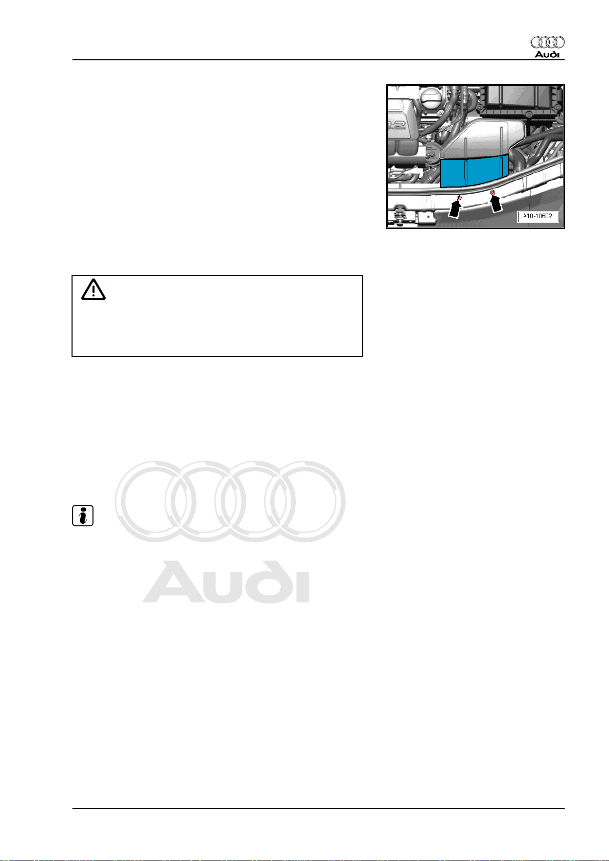
– Detach engine cover panel.
– Using suitable pliers, unfasten clamp at air hose to air duct and
detach hose
– Using suitable pliers, unfasten clamps of air duct and detach.
– Remove air duct to turbocharger from bracket.
– Take air duct out of vehicle.
6. TFSI engine: ABS control unit -J104- and ABS hydraulic unit -N55- 25
Page 32

Protected by copyright. Copying for private or commercial purposes, in part or in whole, is not
permitted unless authorised by AUDI AG. AUDI AG does not guarantee or accept any liability
with respect to the correctness of information in this document. Copyright by AUDI AG.
Audi TT 2007 ➤
Brake system - Edition 04.2009
– Release connector at control unit -arrow 1- and unplug
-arrow 2-.
Note
♦
Make sure brake fluid does not get into connector housing of
control unit. This can result in corrosion of the contacts and
failure of the system.
♦
Use compressed air to carefully clean connector housing if
necessary.
– To protect against escaping brake fluid, place a sufficient
number of lint-free cloths in area beneath control unit and hy‐
draulic unit.
– Mark brake lines ⇒ Item 1 (page 19) .
WARNING
Do not bend or kink brake lines.
– Unscrew brake lines from hydraulic unit -2- to brake master
cylinder and tie in place.
– Disconnect remaining brake lines -3- on hydraulic unit.
– Seal brake lines and threaded holes using sealing plugs from
repair kit.
Note
The hydraulic pump must not be separated from the hydraulic
unit.
26 Rep. Gr.45 - Anti-lock brake system
Page 33

Protected by copyright. Copying for private or commercial purposes, in part or in whole, is not
permitted unless authorised by AUDI AG. AUDI AG does not guarantee or accept any liability
with respect to the correctness of information in this document. Copyright by AUDI AG.
– Carefully pull hydraulic unit -2- together with control unit and
bracket -4- out of rubber buffers on mounting bracket -6-.
– Take hydraulic unit out of vehicle.
– Unscrew bolts -5- from bracket -4- and detach bracket.
– Place hydraulic unit on a clean flat surface with control unit
facing downwards.
WARNING
Severe shocks or jolts can damage the control unit. The control
unit must not be re-installed if it has been damaged in any way.
Seal threaded holes and brake lines using sealing plugs 1H0.698.311.A after removing control unit and hydraulic unit.
WARNING
Hydraulic pump must not be separated from hydraulic unit.
Audi TT 2007 ➤
Brake system - Edition 04.2009
Installing
Installation is performed in reverse sequence; note the following:
Note
♦
The hydraulic unit supplied as a replacement is filled with
brake fluid.
♦
If sealing plugs are removed before fitting corresponding
brake line, brake fluid will escape. Proper bleeding is then no
longer ensured.
6. TFSI engine: ABS control unit -J104- and ABS hydraulic unit -N55- 27
Page 34

Protected by copyright. Copying for private or commercial purposes, in part or in whole, is not
permitted unless authorised by AUDI AG. AUDI AG does not guarantee or accept any liability
with respect to the correctness of information in this document. Copyright by AUDI AG.
Audi TT 2007 ➤
Brake system - Edition 04.2009
– Secure bracket -4- by tightening bolts -5- to 8 Nm.
– Carefully insert hydraulic unit -2- together with control unit and
bracket -4- in rubber buffers on mounting bracket -6-.
Make sure that rubber buffers are not pressed through mounting
bracket when inserting unit.
– Connect brake lines as previously marked
⇒ Item 1 (page 19) .
WARNING
Interchanging brake line connections will result in ESP system
malfunction.
– Connect brake lines to hydraulic unit.
– Attach connector to control unit and lock connector.
– Insert air duct for turbocharger and use suitable pliers to fasten
clamps.
– Secure air duct for turbocharger at bracket.
– Connect air hose and use suitable pliers to fasten clamp.
– Install engine cover panel.
– Bleed brake system ⇒ page 109 .
– Perform final control diagnosis after securing brake lines to
hydraulic unit.
To do this, use vehicle diagnosis, testing and information system
-VAS 505x- .
Note
Final control diagnosis can be used to establish whether line con‐
nections have been interchanged.
If a new ABS control unit -J104- has been fitted, it must be enco‐
ded.
To do this, use vehicle diagnosis, testing and information system
-VAS 505x- .
– Select on the display:
♦ Running gear
♦ Brake system (Repair group 01; 45)
♦ 01 - Self-diagnosis compatible systems
♦ 03 - Brake electronics ABS/ESP Mark 60
– Select required function on the display.
♦ J104 - Control unit for ABS/TCS/ESP Mark 60
♦ J104 - Control unit for ABS/TCS/ESP, Functions
♦ J104 - Encoding control unit
Also calibrate the following senders after renewing control unit J104-.
♦ Steering angle sender -G85-
♦ Lateral acceleration sender -G200-
28 Rep. Gr.45 - Anti-lock brake system
Page 35

Protected by copyright. Copying for private or commercial purposes, in part or in whole, is not
permitted unless authorised by AUDI AG. AUDI AG does not guarantee or accept any liability
with respect to the correctness of information in this document. Copyright by AUDI AG.
♦ Brake pressure sender 1 -G201-
♦ Longitudinal acceleration sender -G251- (only on four-wheel
drive vehicles)
To do this, use vehicle diagnosis, testing and information system
-VAS 505x- .
– Select on the display:
♦ Running gear
♦ Brake system
♦ 01 - Self-diagnosis compatible systems
♦ 03 - Brake electronics ABS/ESP Mark 60
– Select required function on the display.
♦ J104 - Control unit for ABS/TCS/ESP Mark 60
♦ J104 - Control unit for ABS/TCS/ESP, Functions
– Then carry out ESP road test and system test.
WARNING
Audi TT 2007 ➤
Brake system - Edition 04.2009
Before driving vehicle for the first time, make sure function of
brakes is OK.
6.2 Removing and installing control unit J104- with hydraulic unit -N55- (TT RS)
Caution
ABS control unit -J104- and ABS hydraulic unit -N55- must not
be separated.
Removing hydraulic unit with control unit
– Read out control unit version and note down.
– Disconnect battery ⇒ Electrical system; Rep. Gr. 27 (note
radio code).
6. TFSI engine: ABS control unit -J104- and ABS hydraulic unit -N55- 29
Page 36

Protected by copyright. Copying for private or commercial purposes, in part or in whole, is not
permitted unless authorised by AUDI AG. AUDI AG does not guarantee or accept any liability
with respect to the correctness of information in this document. Copyright by AUDI AG.
Audi TT 2007 ➤
Brake system - Edition 04.2009
– Insert brake pedal actuator -V.A.G 1869/2- between brake
pedal and driver's seat (depress brake pedal at least 60 mm).
– Connect hose of bleeder bottle to bleeder screws of front left
and rear left brake calipers.
– Open bleeder screws of rear left and front left brake calipers
to release pressure in hydraulic unit.
– Close bleeder screws of front left and rear left brake calipers.
– Do not remove brake pedal actuator -V.A.G 1869/2- .
– Lower vehicle.
– Using suitable pliers, unfasten clamp at air hose to air duct and
detach hose.
– Using suitable pliers, unfasten clamps of air duct and detach.
– Remove air duct to turbocharger from bracket.
– Take air duct out of vehicle.
– Unclip coolant line to coolant expansion tank from bulkhead.
– Carefully press coolant line to one side.
– Release connector at control unit -arrow 1- and unplug
-arrow 2-.
Note
♦
Make sure brake fluid does not get into connector housing of
control unit. This can result in corrosion of the contacts and
failure of the system.
♦
Use compressed air to carefully clean connector housing if
necessary.
– Unfasten cable tie for electrical wiring to connector and move
wiring clear to one side.
– To protect against escaping brake fluid, place a sufficient
number of lint-free cloths in area beneath control unit and hy‐
draulic unit.
– Mark brake lines ⇒ Item 1 (page 19) .
WARNING
Do not bend or kink brake lines.
30 Rep. Gr.45 - Anti-lock brake system
Page 37

Protected by copyright. Copying for private or commercial purposes, in part or in whole, is not
permitted unless authorised by AUDI AG. AUDI AG does not guarantee or accept any liability
with respect to the correctness of information in this document. Copyright by AUDI AG.
– Unscrew brake lines from hydraulic unit -2- to brake master
cylinder and tie in place.
– Disconnect remaining brake lines -3- on hydraulic unit.
– Seal brake lines and threaded holes using sealing plugs from
repair kit.
Note
The hydraulic pump must not be separated from the hydraulic
unit.
– Carefully pull hydraulic unit -2- together with control unit and
bracket -4- out of rubber buffers on mounting bracket -6-.
– Take hydraulic unit out of vehicle.
– Unscrew bolts -5- from bracket -4- and detach bracket.
– Place hydraulic unit on a clean flat surface with control unit
facing downwards.
Audi TT 2007 ➤
Brake system - Edition 04.2009
WARNING
Severe shocks or jolts can damage the control unit. The control
unit must not be re-installed if it has been damaged in any way.
Seal threaded holes and brake lines using sealing plugs 1H0.698.311.A after removing control unit and hydraulic unit.
WARNING
Hydraulic pump must not be separated from hydraulic unit.
Installing
Installation is performed in reverse sequence; note the following:
Note
♦
The hydraulic unit supplied as a replacement is filled with
brake fluid.
♦
If sealing plugs are removed before fitting corresponding
brake line, brake fluid will escape. Proper bleeding is then no
longer ensured.
6. TFSI engine: ABS control unit -J104- and ABS hydraulic unit -N55- 31
Page 38

Protected by copyright. Copying for private or commercial purposes, in part or in whole, is not
permitted unless authorised by AUDI AG. AUDI AG does not guarantee or accept any liability
with respect to the correctness of information in this document. Copyright by AUDI AG.
Audi TT 2007 ➤
Brake system - Edition 04.2009
– Secure bracket -4- by tightening bolts -5- to 8 Nm.
– Carefully insert hydraulic unit -2- together with control unit and
bracket -4- in rubber buffers on mounting bracket -6-.
Make sure that rubber buffers are not pressed through mounting
bracket when inserting unit.
– Connect brake lines as previously marked
⇒ Item 1 (page 19) .
WARNING
Interchanging brake line connections will result in ESP system
malfunction.
– Connect brake lines to hydraulic unit.
– Attach connector to control unit and lock connector.
– Secure electrical wiring for connector to body using a cable
tie.
– Clip coolant line to coolant expansion tank into retainers in
bulkhead.
Note
Fasten retainers at bulkhead.
– Insert air duct for turbocharger and use suitable pliers to fasten
clamps.
– Secure air duct for turbocharger at bracket.
– Connect air hose and use suitable pliers to fasten clamp.
– Bleed brake system ⇒ page 109 .
– Perform final control diagnosis after securing brake lines to
hydraulic unit.
To do this, use vehicle diagnosis, testing and information system
-VAS 505x- .
Note
Final control diagnosis can be used to establish whether line con‐
nections have been interchanged.
If a new ABS control unit -J104- has been fitted, it must be enco‐
ded.
To do this, use vehicle diagnosis, testing and information system
-VAS 505x- .
– Select on the display:
♦ Running gear
♦ Brake system (Repair group 01; 45)
♦ 01 - Self-diagnosis compatible systems
♦ 03 - Brake electronics ABS/ESP Mark 60
– Select required function on the display.
♦ J104 - Control unit for ABS/TCS/ESP Mark 60
32 Rep. Gr.45 - Anti-lock brake system
Page 39

Protected by copyright. Copying for private or commercial purposes, in part or in whole, is not
permitted unless authorised by AUDI AG. AUDI AG does not guarantee or accept any liability
with respect to the correctness of information in this document. Copyright by AUDI AG.
♦ J104 - Control unit for ABS/TCS/ESP, Functions
♦ J104 - Encoding control unit
Also calibrate the following senders after renewing control unit J104-.
♦ Steering angle sender -G85-
♦ Lateral acceleration sender -G200-
♦ Brake pressure sender 1 -G201-
♦ Longitudinal acceleration sender -G251- (only on four-wheel
drive vehicles)
To do this, use vehicle diagnosis, testing and information system
-VAS 505x- .
– Select on the display:
♦ Running gear
♦ Brake system
♦ 01 - Self-diagnosis compatible systems
♦ 03 - Brake electronics ABS/ESP Mark 60
– Select required function on the display.
♦ J104 - Control unit for ABS/TCS/ESP Mark 60
♦ J104 - Control unit for ABS/TCS/ESP, Functions
– Then carry out ESP road test and system test.
Audi TT 2007 ➤
Brake system - Edition 04.2009
WARNING
Before driving vehicle for the first time, make sure function of
brakes is OK.
6. TFSI engine: ABS control unit -J104- and ABS hydraulic unit -N55- 33
Page 40

Protected by copyright. Copying for private or commercial purposes, in part or in whole, is not
permitted unless authorised by AUDI AG. AUDI AG does not guarantee or accept any liability
with respect to the correctness of information in this document. Copyright by AUDI AG.
Audi TT 2007 ➤
Brake system - Edition 04.2009
7 Vehicles with diesel particulate filter:
Control unit -J104- with hydraulic unit
-N55-
7.1 Removing and installing control unit J104- with hydraulic unit -N55- (TDI)
Note
The diesel particulate filter must be removed ⇒ Rep. Gr. 26 .
Special tools and workshop
equipment required
♦ Torque wrench -V.A.G
1331-
♦ Torque wrench -V.A.G
1410-
♦ Brake pedal actuator -
V.A.G 1869/2-
34 Rep. Gr.45 - Anti-lock brake system
Page 41

Protected by copyright. Copying for private or commercial purposes, in part or in whole, is not
permitted unless authorised by AUDI AG. AUDI AG does not guarantee or accept any liability
with respect to the correctness of information in this document. Copyright by AUDI AG.
Sealing plug repair kit, Part no. 1H0 698 311 A
No warranty can be assumed for hydraulic units without transport
protection.
1 - Transport protection for valve domes (foam)
2 - Sealing plugs M10 for brake lines and tapped holes
3 - Sealing plugs M12 for brake lines and tapped holes
Caution
ABS control unit -J104- and ABS hydraulic unit -N55- must not
be separated.
Removing hydraulic unit with control unit
– Read out control unit version and note down.
– Disconnect battery ⇒ Electrical system; Rep. Gr. 27 (note
radio code).
– Insert brake pedal actuator -V.A.G 1869/2- between brake
pedal and driver's seat. Depress the brake pedal at least
60 mm.
– Connect hose of bleeder bottle to bleeder screws of front left
and rear left brake calipers and open bleeder screws.
Audi TT 2007 ➤
Brake system - Edition 04.2009
Note
This will release the pressure in the hydraulic unit.
– Close front left and rear left bleeder screws.
– Do not remove brake pedal actuator -V.A.G 1869/2- .
– Lower vehicle.
– Remove engine cover panel.
– Remove diesel particulate filter ⇒ Rep. Gr. 26 .
7. Vehicles with diesel particulate filter: Control unit -J104- with hydraulic unit -N55- 35
Page 42

Protected by copyright. Copying for private or commercial purposes, in part or in whole, is not
permitted unless authorised by AUDI AG. AUDI AG does not guarantee or accept any liability
with respect to the correctness of information in this document. Copyright by AUDI AG.
Audi TT 2007 ➤
Brake system - Edition 04.2009
– Release connector at control unit -arrow 1- and unplug
-arrow 2-.
Note
♦
Make sure brake fluid does not get into connector housing of
control unit. This can result in corrosion of the contacts and
failure of the system.
♦
Use compressed air to carefully clean connector housing if
necessary.
– As protection against escaping brake fluid, place a sufficient
number of lint-free cloths in area beneath control unit and hy‐
draulic unit.
– Mark brake lines.
– Unscrew brake lines from hydraulic unit -1- to brake master
cylinder and tie in place.
– Disconnect remaining brake lines -2- on hydraulic unit.
WARNING
Do not bend or kink the brake lines in the vicinity of the hy‐
draulic unit.
– Seal brake lines and tapped holes with sealing plugs from re‐
pair kit.
36 Rep. Gr.45 - Anti-lock brake system
Page 43

Protected by copyright. Copying for private or commercial purposes, in part or in whole, is not
permitted unless authorised by AUDI AG. AUDI AG does not guarantee or accept any liability
with respect to the correctness of information in this document. Copyright by AUDI AG.
– Carefully pull hydraulic unit -2- together with control unit and
bracket -4- out of rubber buffers -6-.
– Take hydraulic unit out of vehicle.
– Unscrew bolts -5- from bracket -4- and detach bracket.
– Place hydraulic unit on a clean flat surface with control unit
facing downwards.
WARNING
Severe shocks or jolts can damage the control unit. The control
unit must not be re-installed if it has been damaged in any way.
Seal threaded holes and brake lines using sealing plugs
1H0.698.311.A after removing control unit and hydraulic unit.
WARNING
Hydraulic pump must not be separated from hydraulic unit.
Audi TT 2007 ➤
Brake system - Edition 04.2009
Installing
Installation is performed in reverse sequence; note the following:
Note
♦
The hydraulic unit supplied as a replacement is filled with
brake fluid.
♦
If sealing plugs are removed before fitting corresponding
brake line, brake fluid will escape. Proper bleeding is then no
longer ensured.
7. Vehicles with diesel particulate filter: Control unit -J104- with hydraulic unit -N55- 37
Page 44

Protected by copyright. Copying for private or commercial purposes, in part or in whole, is not
permitted unless authorised by AUDI AG. AUDI AG does not guarantee or accept any liability
with respect to the correctness of information in this document. Copyright by AUDI AG.
Audi TT 2007 ➤
Brake system - Edition 04.2009
– Secure mounting bracket -4- with bolts -5-. Tightening torque:
8 Nm.
– Carefully insert hydraulic unit -2- together with control unit and
bracket -4- in rubber buffers on mounting bracket -6-.
Make sure that rubber buffers are not pressed through mounting
bracket when inserting unit.
– Connect brake lines as previously marked.
WARNING
Interchanging brake lines will result in ESP system malfunc‐
tion.
– Connect brake lines to hydraulic unit.
– Attach connector to control unit and lock connector.
– Install diesel particulate filter ⇒ Rep. Gr. 26 .
– Install engine cover panel.
– Bleed brake system ⇒ page 109 .
– Perform final control diagnosis after securing brake lines to
hydraulic unit.
To do this, use vehicle diagnosis, testing and information system
-VAS 505x- .
Note
Final control diagnosis can be used to establish whether line con‐
nections have been interchanged.
If a new ABS control unit -J104- has been fitted, it must be enco‐
ded.
To do this, use vehicle diagnosis, testing and information system
-VAS 505x- .
– Select on the display:
♦ Running gear
♦ Brake system (Repair group 01; 45)
♦ 01 - Self-diagnosis compatible systems
♦ 03 - Brake electronics ABS/ESP Mark 60
– Select required function on the display.
♦ J104 - Control unit for ABS/TCS/ESP Mark 60
♦ J104 - Control unit for ABS/TCS/ESP, Functions
♦ J104 - Encoding control unit
Also calibrate the following senders after renewing control unit J104-.
♦ Steering angle sender -G85-
♦ Lateral acceleration sender -G200-
♦ Brake pressure sender 1 -G201-
♦ Longitudinal acceleration sender -G251- (only on four-wheel
drive vehicles)
38 Rep. Gr.45 - Anti-lock brake system
Page 45

Protected by copyright. Copying for private or commercial purposes, in part or in whole, is not
permitted unless authorised by AUDI AG. AUDI AG does not guarantee or accept any liability
with respect to the correctness of information in this document. Copyright by AUDI AG.
To do this, use vehicle diagnosis, testing and information system
-VAS 505x- .
– Select on the display:
♦ Running gear
♦ Brake system
♦ 01 - Self-diagnosis compatible systems
♦ 03 - Brake electronics ABS/ESP Mark 60
– Select required function on the display.
♦ J104 - Control unit for ABS/TCS/ESP Mark 60
♦ J104 - Control unit for ABS/TCS/ESP, Functions
– Then carry out ESP road test and system test.
WARNING
Before driving vehicle for the first time, make sure function of
brakes is OK.
Audi TT 2007 ➤
Brake system - Edition 04.2009
7.2 Basic setting of inlet valves and sepa‐
rating valves (Mark 60EC)
The basic setting of the inlet valves should only be performed if
the ABS control unit -J104- has been renewed.
To do so, use the vehicle diagnosis, testing and information sys‐
tem -VAS 505x- or -VAS 5052- .
Note
If the basic setting of the inlet valves has to be performed, you
must then perform the basic setting of the separating valves.
♦ Running gear
♦ Brake system
♦ 01 - Self-diagnosis compatible systems
♦ 03 ABS control unit J104 MK60EC
♦ 03 Functions ABS MK60EC J104
♦ Basic setting of inlet valves
♦ Basic setting of separating valves
Please follow the instructions on the display exactly.
7. Vehicles with diesel particulate filter: Control unit -J104- with hydraulic unit -N55- 39
Page 46

Protected by copyright. Copying for private or commercial purposes, in part or in whole, is not
permitted unless authorised by AUDI AG. AUDI AG does not guarantee or accept any liability
with respect to the correctness of information in this document. Copyright by AUDI AG.
Audi TT 2007 ➤
Brake system - Edition 04.2009
8 ABS/ESP system components on
front axle
8.1 Exploded view
Note
The ABS sensor ring / rotor is incorporated in the corresponding
wheel bearing unit ⇒ Rep. Gr. 42 and cannot be renewed.
1 - Speed sensor
❑ Removing and installing
⇒ page 40
2 - Hexagon socket head bolt
❑ 8 Nm
8.2 Removing and installing speed sensor
Removing
– Release connector -1- at speed sensor and unplug.
– Remove bolt -2-.
– Pull speed sensor -1- out of wheel bearing housing.
40 Rep. Gr.45 - Anti-lock brake system
Page 47

Protected by copyright. Copying for private or commercial purposes, in part or in whole, is not
permitted unless authorised by AUDI AG. AUDI AG does not guarantee or accept any liability
with respect to the correctness of information in this document. Copyright by AUDI AG.
Installing
Installation is performed in reverse sequence; note the following:
– Before inserting speed sensor, clean inner surface of hole and
coat speed sensor thoroughly with lubricating paste
G 000 650.
– Turn steering completely to left and right and check clearance
of speed sensor wire.
Audi TT 2007 ➤
Brake system - Edition 04.2009
8. ABS/ESP system components on front axle 41
Page 48

Protected by copyright. Copying for private or commercial purposes, in part or in whole, is not
permitted unless authorised by AUDI AG. AUDI AG does not guarantee or accept any liability
with respect to the correctness of information in this document. Copyright by AUDI AG.
Audi TT 2007 ➤
Brake system - Edition 04.2009
9 ABS/ESP system components on
rear axle (front-wheel drive vehicles)
9.1 Exploded view
Note
The ABS sensor ring / rotor is incorporated in the corresponding
wheel bearing unit ⇒ Rep. Gr. 42 and cannot be renewed.
1 - Hexagon socket head bolt
❑ 8 Nm
2 - Speed sensor
❑ Removing and installing
⇒ page 42
9.2 Removing and installing rear speed sen‐
sor
Removing
– Release connector -2- at speed sensor and unplug.
– Remove bolt -1-.
– Pull speed sensor -2- out of wheel bearing housing.
42 Rep. Gr.45 - Anti-lock brake system
Page 49

Protected by copyright. Copying for private or commercial purposes, in part or in whole, is not
permitted unless authorised by AUDI AG. AUDI AG does not guarantee or accept any liability
with respect to the correctness of information in this document. Copyright by AUDI AG.
Installing
Installation is performed in reverse sequence; note the following:
– Before inserting speed sensor, clean inner surface of fitting
hole and coat speed sensor thoroughly with grease -G 000
650- .
Audi TT 2007 ➤
Brake system - Edition 04.2009
9. ABS/ESP system components on rear axle (front-wheel drive vehicles) 43
Page 50

Protected by copyright. Copying for private or commercial purposes, in part or in whole, is not
permitted unless authorised by AUDI AG. AUDI AG does not guarantee or accept any liability
with respect to the correctness of information in this document. Copyright by AUDI AG.
Audi TT 2007 ➤
Brake system - Edition 04.2009
10 ABS/ESP system components on
rear axle (four-wheel drive vehicles)
10.1 Exploded view
Note
The ABS sensor ring / rotor is incorporated in the corresponding
wheel bearing unit ⇒ Rep. Gr. 42 and cannot be renewed.
1 - Speed sensor
❑ Removing and installing
⇒ page 44
2 - Hexagon socket head bolt
❑ 8 Nm
10.2 Removing and installing rear speed sen‐
sor
Removing
– Release connector -1- at speed sensor and unplug.
– Remove bolt -2-.
– Pull speed sensor -1- out of wheel bearing housing.
44 Rep. Gr.45 - Anti-lock brake system
Page 51

Protected by copyright. Copying for private or commercial purposes, in part or in whole, is not
permitted unless authorised by AUDI AG. AUDI AG does not guarantee or accept any liability
with respect to the correctness of information in this document. Copyright by AUDI AG.
Installing
Installation is performed in reverse sequence; note the following:
– Before inserting speed sensor, clean inner surface of hole and
coat speed sensor thoroughly with lubricating paste
G 000 650.
Audi TT 2007 ➤
Brake system - Edition 04.2009
10. ABS/ESP system components on rear axle (four-wheel drive vehicles) 45
Page 52

Protected by copyright. Copying for private or commercial purposes, in part or in whole, is not
permitted unless authorised by AUDI AG. AUDI AG does not guarantee or accept any liability
with respect to the correctness of information in this document. Copyright by AUDI AG.
Audi TT 2007 ➤
Brake system - Edition 04.2009
46 – Brakes - mechanism
1 Servicing front brakes
Observe general notes before servicing.
Note
♦
Use the brake filling and bleeding equipment -VAS 5234- to
extract brake fluid from brake fluid reservoir.
♦
Before removing brake caliper or disconnecting brake hose
from brake caliper, insert brake pedal actuator -V.A.G 1869/2to prevent brake fluid reservoir from emptying completely.
♦
To draw off brake fluid from brake fluid reservoir use a bleeder
bottle which is used only for brake fluid.
♦
Make sure that no brake fluid escapes, otherwise components
and paintwork will be damaged.
♦
Always install all parts supplied in repair kit.
WARNING
Brake fluid is poisonous and must NOT be sucked through a
hose with the mouth.
1.1 Servicing front brakes 16" FN3
♦ Install all parts supplied in repair kit.
♦ After replacing brake pads, depress brake pedal firmly several
times with vehicle stationary so that the pads are properly
seated in their normal operating position.
Observe general notes ⇒ page 46 .
46 Rep. Gr.46 - Brakes - mechanism
Page 53

Protected by copyright. Copying for private or commercial purposes, in part or in whole, is not
permitted unless authorised by AUDI AG. AUDI AG does not guarantee or accept any liability
with respect to the correctness of information in this document. Copyright by AUDI AG.
Audi TT 2007 ➤
Brake system - Edition 04.2009
1 - Wheel bearing unit with in‐
tegrated ABS sensor wheel
❑ Removing and installing
⇒ Rep. Gr. 40
2 - Speed sensor
❑ Removing and installing
⇒ page 40
3 - Hexagon socket head bolt
❑ 8 Nm
4 - Splash plate
5 - Bolt
❑ 10 Nm
6 - Brake disc
❑ Allocation, dimensions
and wear limit ⇒ page 1
❑ To remove, unbolt brake
caliper housing
❑ Do not force brake discs
off wheel hub; if neces‐
sary, use rust remover,
otherwise brake discs
could be damaged.
❑ Always renew on both
sides of axle
7 - Bolt
❑ Do not loosen unless re‐
moving brake disc
❑ 4 Nm
8 - Brake carrier
❑ Bolt to wheel bearing
housing
❑ 200 Nm
❑ Renew protective caps if they have been damaged (repair kit); use grease sachet supplied to lubricate
the guide pins
9 - Brake pads
❑ With wear indicator (on inner brake pad on left-side only)
❑ Pad thickness, wear limit ⇒ page 1
❑ Always renew on both sides of axle
Before fitting pads, clean guide surfaces and apply a thin coating of grease ⇒ ETKA .
❑ Removing and installing ⇒ page 49
❑ Checking pad thickness: ⇒ Maintenance ; Booklet 808
Note
Clean the brake caliper thoroughly
(grease-free) before inserting new
brake pads. It is particularly impor‐
tant to ensure that contact surfaces
for brake pads are clean.
10 - Retaining spring
❑ Insert in both holes in brake caliper housing
1. Servicing front brakes 47
Page 54

Protected by copyright. Copying for private or commercial purposes, in part or in whole, is not
permitted unless authorised by AUDI AG. AUDI AG does not guarantee or accept any liability
with respect to the correctness of information in this document. Copyright by AUDI AG.
Audi TT 2007 ➤
Brake system - Edition 04.2009
11 - Brake caliper housing
❑ Piston diameter ⇒ page 1 ; versions available ⇒ ETKA
❑ Unscrew from brake carrier to replace brake pads
❑ Removing and installing ⇒ page 52
❑ Servicing ⇒ page 96
Brake line connection to brake caliper, 19 Nm
Brake line connection to brake hose, 12 Nm
Counterhold at hexagon flats on brake hose when connecting brake line to brake hose.
❑ Brake caliper with vibration damper ⇒ page 74
12 - Bracket
13 - Bolt
❑ Bracket to brake caliper
14 - Protective cap
15 - Guide pin
❑ Brake caliper to brake carrier
❑ 30 Nm
16 - Bearing bush
17 - Protective cap
18 - Bolt
❑ Brake carrier to wheel bearing housing
❑ Always renew if removed
❑ 200 Nm
Brake hose connection with locating pin
Tightening torque for brake hose to brake caliper for 16" FN-3
brakes: 35 Nm
– Make sure groove in banjo union of brake hose is inserted on
locating pin -arrow-.
48 Rep. Gr.46 - Brakes - mechanism
Page 55

Protected by copyright. Copying for private or commercial purposes, in part or in whole, is not
permitted unless authorised by AUDI AG. AUDI AG does not guarantee or accept any liability
with respect to the correctness of information in this document. Copyright by AUDI AG.
Audi TT 2007 ➤
Brake system - Edition 04.2009
1.2 Removing and installing brake pads - front brakes 16" FN3
Special tools and workshop equipment required
♦ Torque wrench -V.A.G 1331-
♦ Torque wrench -V.A.G 1410-
♦ Torque wrench -V.A.G 1332-
♦ Brake pedal actuator -V.A.G 1869/2-
♦ Piston resetting appliance -T10145-
Removing
– Raise vehicle.
– Remove wheels.
Note
Mark brake pads when removing them if they are to be reinstalled.
Reinstall in their original position to prevent uneven braking.
1. Servicing front brakes 49
Page 56

Protected by copyright. Copying for private or commercial purposes, in part or in whole, is not
permitted unless authorised by AUDI AG. AUDI AG does not guarantee or accept any liability
with respect to the correctness of information in this document. Copyright by AUDI AG.
Audi TT 2007 ➤
Brake system - Edition 04.2009
– Unplug connector -1- of brake pad wear indicator at left brake.
– Do not loosen bolt -2-.
– Lever off brake pad retaining spring from brake caliper housing
with a screwdriver -arrow- and remove.
– Remove brake caliper. ⇒ page 52
– Remove brake caliper and secure such that the weight of the
caliper does not damage the brake line.
Note
Brake hose/line must not be twisted or kinked.
– Take brake pads out of brake caliper housing or from brake
carrier.
– Clean brake caliper housing; in particular the bonding surface
for the brake pad must be free of any traces of adhesive and
grease.
Only use methylated spirits to clean the brake caliper housing.
Installing
Before fitting pads, clean guides and apply a thin coating of
grease ⇒ ETKA .
Press back brake pistons using piston resetting appliance T10145- when fitting new brake pads ⇒ page 73 .
Make sure that no brake fluid escapes from brake fluid reservoir;
otherwise components and paintwork will be damaged.
To draw off brake fluid from brake fluid reservoir use a bleeder
bottle which is used only for brake fluid.
WARNING
Brake fluid is poisonous and must NOT be sucked through a
hose with the mouth. On account of its corrosive effect it must
also not be allowed to come into contact with paintwork.
Perform further installation in reverse order; note the following:
– Insert brake pads in brake carrier, paying attention to fitting
location:
50 Rep. Gr.46 - Brakes - mechanism
Page 57

Protected by copyright. Copying for private or commercial purposes, in part or in whole, is not
permitted unless authorised by AUDI AG. AUDI AG does not guarantee or accept any liability
with respect to the correctness of information in this document. Copyright by AUDI AG.
When properly installed, arrow on backplate of brake pad must
face downwards.
1 - Right-side brake pad (facing piston)
2 - Left-side brake pad (facing piston)
Note
The wear indicator is located on inner brake pad on front left brake
caliper.
– Pull protective foil off outer brake pad backplate.
– Fit brake caliper onto brake carrier and brake disc.
– Secure brake caliper with both guide pins to brake carrier
⇒ page 52 . Note tightening torque ⇒ Item 15 (page 48) .
Audi TT 2007 ➤
Brake system - Edition 04.2009
1. Servicing front brakes 51
Page 58

Protected by copyright. Copying for private or commercial purposes, in part or in whole, is not
permitted unless authorised by AUDI AG. AUDI AG does not guarantee or accept any liability
with respect to the correctness of information in this document. Copyright by AUDI AG.
Audi TT 2007 ➤
Brake system - Edition 04.2009
– Insert retaining spring -arrow- in brake caliper housing.
Note
Make sure not to twist or stretch brake hose when installing.
– Fit both protective caps onto guide pins.
– Insert retaining spring into brake caliper housing.
– Press in spring clip.
– Plug in connector for wear indicator.
– Press connector for wear indicator into bracket and insert wire.
– Fit wheels ⇒ Wheels and tyres; Rep. Gr. 44 .
WARNING
♦ The retaining spring must be pressed under the brake
carrier after inserting into both holes. If incorrectly instal‐
led, the wear of the outer pad cannot be adjusted, and the
pedal travel will be increased as a result.
♦ After installing the brake pads and bleeding brake system,
depress pedal firmly several times with the vehicle sta‐
tionary, so that the brake pads are properly seated in their
normal operating position.
– Check brake fluid level and top up if necessary.
–
WARNING
After installing the brake pads, depress pedal firmly several
times with the vehicle stationary, so that the brake pads are
properly seated in their normal operating position.
WARNING
Before driving vehicle for the first time, make sure function of
brakes is OK.
1.3 Removing and installing brake caliper front brakes 16" FN3
Special tools and workshop equipment required
52 Rep. Gr.46 - Brakes - mechanism
Page 59

Protected by copyright. Copying for private or commercial purposes, in part or in whole, is not
permitted unless authorised by AUDI AG. AUDI AG does not guarantee or accept any liability
with respect to the correctness of information in this document. Copyright by AUDI AG.
♦ Brake pedal actuator -V.A.G 1869/2-
Removing
– Insert brake pedal actuator -V.A.G 1869/2- between brake
pedal and driver's seat (depress brake pedal at least 60 mm).
Note
This closes the valves in the brake master cylinder and stops the
brake fluid reservoir from running empty.
Audi TT 2007 ➤
Brake system - Edition 04.2009
– Connect hose of bleeder bottle to bleeder screw of removed
brake caliper.
– Open bleeder screw.
– Do not remove brake pedal actuator -V.A.G 1869/2- .
– Close bleeder screws.
– Disconnect brake hose from brake caliper.
– Remove protective caps from guide pins -arrows-.
1. Servicing front brakes 53
Page 60

Protected by copyright. Copying for private or commercial purposes, in part or in whole, is not
permitted unless authorised by AUDI AG. AUDI AG does not guarantee or accept any liability
with respect to the correctness of information in this document. Copyright by AUDI AG.
Audi TT 2007 ➤
Brake system - Edition 04.2009
– Remove guide pins -arrows-.
– Pull both guide pins out of brake caliper and bearing bushes.
– Remove brake pads ⇒ page 49 .
Installing
Installation is performed in reverse sequence; note the following:
– Remove brake pedal actuator -V.A.G 1869/2- .
Press back brake pistons using piston resetting appliance T10145- when fitting new brake pads ⇒ page 73 .
Make sure that no brake fluid escapes from brake fluid reservoir;
otherwise components and paintwork will be damaged.
To draw off brake fluid from brake fluid reservoir use a bleeder
bottle which is used only for brake fluid.
WARNING
Brake fluid is poisonous and must NOT be sucked through a
hose with the mouth. On account of its corrosive effect it must
also not be allowed to come into contact with paintwork.
– Install brake pads ⇒ page 49 .
– Secure brake caliper with both guide pins to brake carrier
⇒ page 52 . Note tightening torque ⇒ Item 15 (page 48) .
– Secure brake hose to brake caliper.
Brake hose connection with locating pin
Tightening torque for brake hose to brake caliper for 16" FN-3
brakes: 35 Nm
– Make sure groove in banjo union of brake hose is inserted on
locating pin -arrow-.
– Bleed brake system ABS/ESP Mark 60 ⇒ page 109 .
– Fit wheels ⇒ Wheels and tyres; Rep. Gr. 44 .
WARNING
After installing the brake pads, depress pedal firmly several
times with the vehicle stationary, so that the brake pads are
properly seated in their normal operating position.
WARNING
Before driving vehicle for the first time, make sure function of
brakes is OK.
54 Rep. Gr.46 - Brakes - mechanism
Page 61

Protected by copyright. Copying for private or commercial purposes, in part or in whole, is not
permitted unless authorised by AUDI AG. AUDI AG does not guarantee or accept any liability
with respect to the correctness of information in this document. Copyright by AUDI AG.
2 Servicing front brakes 17" FNR G57
♦ Install all parts supplied in repair kit.
♦ After replacing brake pads, depress brake pedal firmly several
times with vehicle stationary so that the pads are properly
seated in their normal operating position.
Observe general notes ⇒ page 46 .
1 - Brake disc
❑ Always renew on both
sides of axle
❑ Detach brake caliper
prior to removing
❑ Lubricate contact surfa‐
ces between brake disc
and wheel hub with pol‐
ycarbamide grease -G
052 142 A2- . ⇒ Rep.
Gr. 44
❑ Allocation, dimensions
and wear limit ⇒ page 1
❑ Checking thickness
⇒ Maintenance ; Book‐
let 808
2 - Retaining spring
❑ Ensure correct installa‐
tion position
3 - Brake caliper housing
❑ Piston diameter
⇒ page 1 ⇒ ETKA
❑ Unscrew from brake
carrier to replace brake
pads
❑ Removing and installing
⇒ page 60
❑ Servicing brake caliper
⇒ page 100
❑ Brake caliper with vibra‐
tion damper
⇒ page 74
4 - Bearing bush
❑ Insert into brake caliper
housing
5 - Guide pin
❑ 30 Nm
6 - Protective cap
Audi TT 2007 ➤
Brake system - Edition 04.2009
7 - Cable retainer for wear indicator
8 - Bolt
❑ Cable retainer to brake caliper
❑ 25 Nm
9 - Protective cap
10 - Bolt
❑ Bracket for brake line to brake caliper
2. Servicing front brakes 17" FNR G57 55
Page 62

Protected by copyright. Copying for private or commercial purposes, in part or in whole, is not
permitted unless authorised by AUDI AG. AUDI AG does not guarantee or accept any liability
with respect to the correctness of information in this document. Copyright by AUDI AG.
Audi TT 2007 ➤
Brake system - Edition 04.2009
❑ 15 Nm
11 - Bracket for brake line
❑ Bolt to brake caliper housing
❑ Attach brake line
12 - Brake line
❑ Screw into brake caliper housing with ⇒ Item 11 (page 56)
❑ Do not twist hose when fitting
♦ Brake line connection to brake caliper, 14 Nm
♦ Brake line connection to brake hose, 14 Nm
♦ Counterhold at hexagon flats on brake hose when connecting brake line to brake hose.
13 - Spring clip
❑ Secures brake line in bracket ⇒ Item 11 (page 56)
14 - Brake pads
❑ With wear indicator (on inner brake pad on left-side only)
❑ Pad thickness, wear limit ⇒ page 1
❑ Removing and installing ⇒ page 57
Before fitting pads, clean guide surfaces and apply a thin coating of grease ⇒ ETKA .
❑ Always renew on both sides of axle
❑ Checking pad thickness: ⇒ Maintenance ; Booklet 808
Note
Clean the brake caliper thoroughly
(grease-free) before inserting new
brake pads. It is particularly impor‐
tant to ensure that contact surfaces
for brake pads are clean.
15 - Brake carrier
❑ Bolt to wheel bearing housing
❑ 200 Nm
16 - Bolt
❑ Brake carrier to wheel bearing housing
❑ Always renew if removed
❑ 200 Nm
56 Rep. Gr.46 - Brakes - mechanism
Page 63

Protected by copyright. Copying for private or commercial purposes, in part or in whole, is not
permitted unless authorised by AUDI AG. AUDI AG does not guarantee or accept any liability
with respect to the correctness of information in this document. Copyright by AUDI AG.
Audi TT 2007 ➤
Brake system - Edition 04.2009
2.1 Removing and installing brake pads - front brakes 17" FNR G57
Special tools and workshop equipment required
♦ Torque wrench -V.A.G 1331-
♦ Torque wrench -V.A.G 1410-
♦ Torque wrench -V.A.G 1332-
♦ Brake pedal actuator -V.A.G 1869/2-
♦ Piston resetting appliance -T10145-
Removing
Note
♦
Mark brake pads when removing them if they are to be rein‐
stalled. Reinstall in their original position to prevent uneven
braking.
♦
When installing brake discs, note direction of travel -indicated
by arrow on brake disc- and fitting location -left or right-.
– Raise vehicle.
2. Servicing front brakes 17" FNR G57 57
Page 64

Protected by copyright. Copying for private or commercial purposes, in part or in whole, is not
permitted unless authorised by AUDI AG. AUDI AG does not guarantee or accept any liability
with respect to the correctness of information in this document. Copyright by AUDI AG.
Audi TT 2007 ➤
Brake system - Edition 04.2009
– Remove wheels.
– Fit wheels ⇒ Wheels and tyres; Rep. Gr. 44 .
– Lever brake pad retaining spring out of brake caliper housing
with a screwdriver and remove.
Loosen bolt -1- only when removing brake disc (4 Nm).
– Unplug connector for brake pad wear indicator -1-.
– Do not loosen bolt -2-.
– Unplug connector for brake pad wear indicator from bracket
and detach wire.
58 Rep. Gr.46 - Brakes - mechanism
Page 65

Protected by copyright. Copying for private or commercial purposes, in part or in whole, is not
permitted unless authorised by AUDI AG. AUDI AG does not guarantee or accept any liability
with respect to the correctness of information in this document. Copyright by AUDI AG.
– Take spring clip -arrow- out of bracket for brake line.
– Detach brake line from bracket.
– Remove bolt and detach bracket for brake line.
– Remove brake caliper ⇒ page 60 .
– Remove brake caliper and secure such that the weight of the
caliper does not damage the brake line.
Note
Brake hose/line must not be twisted or kinked.
– Take brake pads out of brake caliper housing or from brake
carrier.
– Clean brake caliper housing; in particular the bonding surface
for the brake pad must be free of any traces of adhesive and
grease.
Only use methylated spirits to clean the brake caliper housing.
Installing
Before fitting pads, clean guide surfaces and apply a thin coating
of grease ⇒ ETKA .
Press back brake pistons using piston resetting appliance T10145- when fitting new brake pads ⇒ page 73 .
Make sure that no brake fluid escapes from brake fluid reservoir;
otherwise components and paintwork will be damaged.
To draw off brake fluid from brake fluid reservoir use a bleeder
bottle which is used only for brake fluid.
Audi TT 2007 ➤
Brake system - Edition 04.2009
WARNING
Brake fluid is poisonous and must NOT be sucked through a
hose with the mouth. On account of its corrosive effect it must
also not be allowed to come into contact with paintwork.
Perform further installation in reverse order; note the following:
Note
The wear indicator is located on inner brake pad on front left brake
caliper.
– Insert brake pad with retaining spring and wear indicator into
brake caliper housing (piston).
2. Servicing front brakes 17" FNR G57 59
Page 66

Protected by copyright. Copying for private or commercial purposes, in part or in whole, is not
permitted unless authorised by AUDI AG. AUDI AG does not guarantee or accept any liability
with respect to the correctness of information in this document. Copyright by AUDI AG.
Audi TT 2007 ➤
Brake system - Edition 04.2009
– Fit outer brake pad -2- in brake caliper.
– The wear indicator wire is fitted to the inner pad -1- at front left
wheel.
– Fit brake caliper together with inserted brake pads onto brake
carrier and brake disc.
– Secure brake caliper housing with both guide pins to brake
carrier. ⇒ page 60 Note specified tightening torque.
⇒ Item 5 (page 55)
Note
Make sure not to twist or stretch brake hose when installing.
– Fit both protective caps.
– Secure bracket for brake line.
– Insert retaining spring into brake caliper housing.
– Attach brake line to bracket.
– Press in spring clip.
– Plug in connector for wear indicator.
– Press connector for wear indicator into bracket and insert wire.
– Fit wheels ⇒ Wheels and tyres; Rep. Gr. 44 .
Note
The retaining spring must be pushed under the brake carrier after
engaging onto both studs. If incorrectly installed, the wear of the
outer pad cannot be adjusted, and the pedal travel will be in‐
creased as a result.
Note
Check that the brake caliper moves freely by moving it from side
to side.
– Check brake fluid level and top up if necessary.
WARNING
After installing the brake pads, depress pedal firmly several
times with the vehicle stationary, so that the brake pads are
properly seated in their normal operating position.
WARNING
Before driving vehicle for the first time, make sure function of
brakes is OK.
2.2 Removing and installing brake caliper front brakes 17" FNR G57
Special tools and workshop equipment required
60 Rep. Gr.46 - Brakes - mechanism
Page 67

Protected by copyright. Copying for private or commercial purposes, in part or in whole, is not
permitted unless authorised by AUDI AG. AUDI AG does not guarantee or accept any liability
with respect to the correctness of information in this document. Copyright by AUDI AG.
♦ Brake pedal actuator -V.A.G 1869/2-
Removing
– Insert brake pedal actuator -V.A.G 1869/2- between brake
pedal and driver's seat (depress brake pedal at least 60 mm).
Note
This closes the valves in the brake master cylinder and stops the
brake fluid reservoir from running empty.
Audi TT 2007 ➤
Brake system - Edition 04.2009
– Connect hose of bleeder bottle to bleeder screw of removed
brake caliper.
– Open bleeder screw.
– Do not remove brake pedal actuator -V.A.G 1869/2- .
– Close bleeder screws.
– Disconnect brake hose from brake caliper.
– Remove protective caps from guide pins -arrows-.
2. Servicing front brakes 17" FNR G57 61
Page 68

Protected by copyright. Copying for private or commercial purposes, in part or in whole, is not
permitted unless authorised by AUDI AG. AUDI AG does not guarantee or accept any liability
with respect to the correctness of information in this document. Copyright by AUDI AG.
Audi TT 2007 ➤
Brake system - Edition 04.2009
– Remove guide pins -arrows-.
– Pull both guide pins out of brake caliper and bearing bushes.
– Remove brake pads ⇒ page 57 .
Installing
Installation is performed in reverse sequence; note the following:
– Remove brake pedal actuator -V.A.G 1869/2- .
Press back brake pistons using piston resetting appliance T10145- when fitting new brake pads ⇒ page 73 .
Make sure that no brake fluid escapes from brake fluid reservoir;
otherwise components and paintwork will be damaged.
To draw off brake fluid from brake fluid reservoir use a bleeder
bottle which is used only for brake fluid.
WARNING
Brake fluid is poisonous and must NOT be sucked through a
hose with the mouth. On account of its corrosive effect it must
also not be allowed to come into contact with paintwork.
– Install brake pads ⇒ page 57 .
– Push both guide pins through bearing bushes into brake cali‐
per.
– Secure brake caliper housing with both guide pins to brake
carrier. Note specified tightening torque ⇒ Item 5 (page 55) .
– Secure brake hose to brake caliper.
Tightening torque for brake hose to brake caliper for 17" FNRG57 brakes: 14 Nm
– Bleed brake system ABS/ESP Mark 60 ⇒ page 109 .
Note
♦
Check that the brake caliper moves freely by moving it from
side to side.
♦
Fit wheels ⇒ Wheels and tyres; Rep. Gr. 44 .
– Lower vehicle.
WARNING
After installing the brake pads, depress pedal firmly several
times with the vehicle stationary, so that the brake pads are
properly seated in their normal operating position.
WARNING
Before driving vehicle for the first time, make sure function of
brakes is OK.
62 Rep. Gr.46 - Brakes - mechanism
Page 69

Protected by copyright. Copying for private or commercial purposes, in part or in whole, is not
permitted unless authorised by AUDI AG. AUDI AG does not guarantee or accept any liability
with respect to the correctness of information in this document. Copyright by AUDI AG.
3 Servicing front brakes (TT RS)
♦ Install all parts supplied in repair kit.
♦ After replacing brake pads, depress brake pedal firmly several
times with vehicle stationary so that the pads are properly
seated in their normal operating position.
1 - Bleeder screw
❑ 10 Nm
Note
2 - Bolt
❑ Unscrew for removal of
brake caliper
❑ 200 Nm
Note
Audi TT 2007 ➤
Brake system - Edition 04.2009
3 - Speed sensor
4 - Bolt
❑ For speed sensor
❑ 8 Nm
5 - Brake caliper
Note
❑ Removing and installing
⇒ page 67
❑ Renewing ⇒ page 69
6 - Brake disc
❑ Wear limit ⇒ page 1
Note
❑ Removing and installing
⇒ page 71
7 - Bolt
❑ For securing brake disc
❑ 4 Nm
Note
8 - Brake pads
❑ With brake pad wear cable (only in left brake caliper)
❑ Wear limit ⇒ page 1
❑ Removing and installing ⇒ page 64
Before fitting pads, clean guides and apply a thin coating of grease ⇒ ETKA .
Before fitting pads, peel off adhesive foil
9 - Brake pad wear cable
❑ Only installed in left brake caliper
3. Servicing front brakes (TT RS) 63
Page 70

Protected by copyright. Copying for private or commercial purposes, in part or in whole, is not
permitted unless authorised by AUDI AG. AUDI AG does not guarantee or accept any liability
with respect to the correctness of information in this document. Copyright by AUDI AG.
Audi TT 2007 ➤
Brake system - Edition 04.2009
10 - Retaining clip
❑ Ensure correct installation position
Note
11 - Brake pad retaining pins
Note
12 - Bolt
❑ For bracket
❑ 18 Nm
13 - Brake hose
❑ Screw into brake caliper
❑ Insert in bracket
❑ 35 Nm
Tightening torque for brake hose to brake caliper for TT RS: 35 Nm
Note
14 - Bracket
❑ For brake hose and brake pad wear cable
3.1 Removing and installing brake pads front brakes (TT RS)
Special tools and workshop equipment required
♦ Piston resetting appliance -T10145-
Mark brake pads when removing them if they are to be reinstalled.
Reinstall in their original position to prevent uneven braking.
Removing
– Raise vehicle.
– Remove wheels.
Note
Note
The brake pad wear cable is only installed at the left brake caliper.
64 Rep. Gr.46 - Brakes - mechanism
Page 71

Protected by copyright. Copying for private or commercial purposes, in part or in whole, is not
permitted unless authorised by AUDI AG. AUDI AG does not guarantee or accept any liability
with respect to the correctness of information in this document. Copyright by AUDI AG.
– Unclip brake pad wear cable -9- from bracket.
Note
Do not loosen bolts -2-.
– Unplug electrical connector from brake pad wear cable.
– Press brake pistons at brake pads slightly back into brake cal‐
iper using a suitable tool.
Note
Take care not to scratch or damage brake caliper.
Audi TT 2007 ➤
Brake system - Edition 04.2009
3. Servicing front brakes (TT RS) 65
Page 72

Protected by copyright. Copying for private or commercial purposes, in part or in whole, is not
permitted unless authorised by AUDI AG. AUDI AG does not guarantee or accept any liability
with respect to the correctness of information in this document. Copyright by AUDI AG.
Audi TT 2007 ➤
Brake system - Edition 04.2009
– Pull brake pad wear cable -9- out of retaining clip -10-.
– Pull one brake pad retaining pin -11- out of brake caliper. While
doing so, press down retaining clip -10-.
– Pull second brake pad retaining pin -11- out of brake caliper.
– Take brake pads out of brake caliper.
Only use methylated spirits to clean the brake caliper housing.
WARNING
Brake fluid is poisonous and must NOT be sucked through a
hose with the mouth. On account of its corrosive effect it must
also not be allowed to come into contact with paintwork.
Installing
If provided, peel adhesive foil off back of brake pads.
Before fitting pads, clean guides and apply a thin coating of
grease ⇒ ETKA .
Press back brake pistons using piston resetting appliance T10145- when fitting new brake pads ⇒ page 73 .
Make sure that no brake fluid escapes from brake fluid reservoir;
otherwise components and paintwork will be damaged.
To draw off brake fluid from brake fluid reservoir use a bleeder
bottle which is used only for brake fluid.
WARNING
Brake fluid is poisonous and must NOT be sucked through a
hose with the mouth. On account of its corrosive effect it must
also not be allowed to come into contact with paintwork.
Perform further installation in reverse order; note the following:
– Insert brake pads into brake caliper.
Note
♦
Make sure that brake pads are seated correctly.
♦
The brake pads with the brake pad wear cable are only fitted
in the left brake caliper.
♦
The brake pad wear cable is fitted in the left brake caliper in
both brake pads.
66 Rep. Gr.46 - Brakes - mechanism
Page 73

Protected by copyright. Copying for private or commercial purposes, in part or in whole, is not
permitted unless authorised by AUDI AG. AUDI AG does not guarantee or accept any liability
with respect to the correctness of information in this document. Copyright by AUDI AG.
– Slide one brake pad retaining pin -11- through brake caliper
and brake pads from inside to outside.
– Insert retaining spring -10- underneath retaining pin -11-.
– Slide second retaining pin through brake caliper and brake
pads from inside to outside. While doing so, press down re‐
taining spring -10-.
WARNING
Both brake pad retaining pins must be pressed through the
brake caliper and the brake pads as far as the stop so that the
spring is seated at the retaining pin in the brake caliper.
– Insert brake pad wear cable -9- in retaining spring -10-.
– Connect brake pad wear cable.
– Insert brake pad wear cable in bracket.
Fit wheels ⇒ Wheels and tyres; Rep. Gr. 44 .
– Lower vehicle.
– Check brake fluid level and top up if necessary.
Audi TT 2007 ➤
Brake system - Edition 04.2009
WARNING
After installing the brake pads, depress pedal firmly several
times with the vehicle stationary, so that the brake pads are
properly seated in their normal operating position.
WARNING
Before driving vehicle for the first time, make sure function of
brakes is OK.
3.2 Removing and installing brake caliper front brakes (TT RS)
Removing
– Raise vehicle.
– Remove wheels.
Note
The brake pad wear cable is only installed at the left brake caliper.
3. Servicing front brakes (TT RS) 67
Page 74

Protected by copyright. Copying for private or commercial purposes, in part or in whole, is not
permitted unless authorised by AUDI AG. AUDI AG does not guarantee or accept any liability
with respect to the correctness of information in this document. Copyright by AUDI AG.
Audi TT 2007 ➤
Brake system - Edition 04.2009
– Unclip brake pad wear cable -9- from bracket.
– Unplug electrical connector from brake pad wear cable.
– Unclip brake hose -13- from bracket.
– Press brake pistons at brake pads slightly back into brake cal‐
iper using a suitable tool.
Note
Take care not to scratch or damage brake caliper.
– Remove bolts -2-.
– Detach brake caliper.
Note
Do not suspend the brake caliper from the brake hose. Secure it
to the body with a suitable wire.
Installing
Note
Renew bolts -2-.
– Carefully slide brake caliper (with brake pads fitted) over brake
disc and install.
68 Rep. Gr.46 - Brakes - mechanism
Page 75

Protected by copyright. Copying for private or commercial purposes, in part or in whole, is not
permitted unless authorised by AUDI AG. AUDI AG does not guarantee or accept any liability
with respect to the correctness of information in this document. Copyright by AUDI AG.
– Secure brake caliper with new bolts -2-. 200 Nm
– Fit brake hose -13- in bracket.
– Connect brake pad wear cable -9-.
– Insert brake pad wear cable in bracket.
Fit wheels ⇒ Wheels and tyres; Rep. Gr. 44 .
– Lower vehicle.
– Check brake fluid level and top up if necessary.
WARNING
Firmly depress the brake pedal several times with the vehicle
stationary, so that the brake pads are properly seated in their
normal operating position.
WARNING
Before driving vehicle for the first time, make sure function of
brakes is OK.
Audi TT 2007 ➤
Brake system - Edition 04.2009
3.3 Renewing brake caliper - front brakes (TT RS)
Note
Mark brake pads when removing them if they are to be reinstalled.
Reinstall in their original position to prevent uneven braking.
Removing
– Raise vehicle.
– Remove wheels.
Note
The brake pad wear cable is only installed at the left brake caliper.
3. Servicing front brakes (TT RS) 69
Page 76

Protected by copyright. Copying for private or commercial purposes, in part or in whole, is not
permitted unless authorised by AUDI AG. AUDI AG does not guarantee or accept any liability
with respect to the correctness of information in this document. Copyright by AUDI AG.
Audi TT 2007 ➤
Brake system - Edition 04.2009
– Insert brake pedal actuator -V.A.G 1869/2- between brake
pedal and driver's seat (depress brake pedal at least 60 mm).
Note
This closes the valves in the brake master cylinder and stops the
brake fluid reservoir from running empty.
– Connect hose of bleeder bottle to bleeder screw of removed
brake caliper.
– Open bleeder screw.
– Do not remove brake pedal actuator -V.A.G 1869/2- .
– Close bleeder screws.
– Disconnect brake hose from brake caliper.
– Remove brake pads ⇒ page 64 .
– Disconnect brake hose -13- from brake caliper.
– Remove bolts -2-. Hold brake caliper in position while doing
so.
– Detach brake caliper.
Installing
Note
Renew bolts -2-.
– Remove brake pedal actuator -V.A.G 1869/2- .
– Install brake caliper.
– Secure brake caliper with new bolts -2-. 200 Nm
Press back brake pistons using piston resetting appliance T10145- when fitting new brake pads ⇒ page 73 .
Make sure that no brake fluid escapes from brake fluid reservoir;
otherwise components and paintwork will be damaged.
To draw off brake fluid from brake fluid reservoir use a bleeder
bottle which is used only for brake fluid.
WARNING
Brake fluid is poisonous and must NOT be sucked through a
hose with the mouth. On account of its corrosive effect it must
also not be allowed to come into contact with paintwork.
– Install brake pads ⇒ page 64 .
70 Rep. Gr.46 - Brakes - mechanism
Page 77

Protected by copyright. Copying for private or commercial purposes, in part or in whole, is not
permitted unless authorised by AUDI AG. AUDI AG does not guarantee or accept any liability
with respect to the correctness of information in this document. Copyright by AUDI AG.
– Attach brake hose -13- to caliper and tighten connection.
Tightening torque for brake hose to brake caliper for TT RS:
35 Nm
– Bleed brake system at all bleeder screws.
Fit wheels ⇒ Wheels and tyres; Rep. Gr. 44 .
– Lower vehicle.
– Check brake fluid level and top up if necessary.
WARNING
After installing the brake pads, depress pedal firmly several
times with the vehicle stationary, so that the brake pads are
properly seated in their normal operating position.
WARNING
Before driving vehicle for the first time, make sure function of
brakes is OK.
Audi TT 2007 ➤
Brake system - Edition 04.2009
3.4 Removing and installing brake disc front brakes (TT RS)
Note
Mark brake pads when removing them if they are to be reinstalled.
Reinstall in their original position to prevent uneven braking.
Removing
– Raise vehicle.
– Remove wheels.
Note
The brake pad wear cable is only installed at the left brake caliper.
– Remove brake caliper ⇒ page 67 .
Note
Do not suspend the brake caliper from the brake hose. Secure it
to the body with a suitable wire.
3. Servicing front brakes (TT RS) 71
Page 78

Protected by copyright. Copying for private or commercial purposes, in part or in whole, is not
permitted unless authorised by AUDI AG. AUDI AG does not guarantee or accept any liability
with respect to the correctness of information in this document. Copyright by AUDI AG.
Audi TT 2007 ➤
Brake system - Edition 04.2009
– Remove bolt -7-.
– Pull brake disc off wheel hub.
Note
Keep brake disc straight while detaching it.
Installing
Note
Always renew bolt -7-.
– Clean contact surfaces on wheel hub and brake disc.
– Fit brake disc onto wheel hub.
Note
Keep brake disc straight while installing it.
– Secure brake disc with new bolt -7- (4 Nm).
– Install brake caliper ⇒ page 67 .
Fit wheels ⇒ Wheels and tyres; Rep. Gr. 44 .
– Lower vehicle.
– Check brake fluid level and top up if necessary.
WARNING
Firmly depress the brake pedal several times with the vehicle
stationary, so that the brake pads are properly seated in their
normal operating position.
WARNING
Before driving vehicle for the first time, make sure function of
brakes is OK.
72 Rep. Gr.46 - Brakes - mechanism
Page 79

Protected by copyright. Copying for private or commercial purposes, in part or in whole, is not
permitted unless authorised by AUDI AG. AUDI AG does not guarantee or accept any liability
with respect to the correctness of information in this document. Copyright by AUDI AG.
4 Pressing back brake piston in front
brake caliper
Special tools and workshop equipment required
♦ Piston resetting appliance -T10145-
Note
Before inserting new brake pads, press brake piston back into
cylinder with resetting appliance. Before pressing the piston back,
draw off brake fluid from the reservoir with a bleeder bottle, oth‐
erwise components can be damaged by escaping brake fluid.
Press back brake pistons using piston resetting appliance T10145- ⇒ page 73 .
Make sure that no brake fluid escapes from brake fluid reservoir;
otherwise components and paintwork will be damaged.
To draw off brake fluid from brake fluid reservoir use a bleeder
bottle which is used only for brake fluid.
Audi TT 2007 ➤
Brake system - Edition 04.2009
WARNING
Brake fluid is poisonous and must NOT be sucked through a
hose with the mouth. On account of its corrosive effect it must
also not be allowed to come into contact with paintwork.
Pressing piston back
Pressing piston back
4. Pressing back brake piston in front brake caliper 73
Page 80

Protected by copyright. Copying for private or commercial purposes, in part or in whole, is not
permitted unless authorised by AUDI AG. AUDI AG does not guarantee or accept any liability
with respect to the correctness of information in this document. Copyright by AUDI AG.
Audi TT 2007 ➤
Brake system - Edition 04.2009
5 Vibration damper on brake caliper -
front brakes
The vibration damper is not fitted with all models. This has no
influence on removal, installation and servicing of the brake cali‐
per.
1 - Dust cap
2 - Bolt
❑ Always renew
❑ 10 Nm
3 - Vibration damper
❑ Removing and installing
⇒ page 74
4 - Washer
5 - Brake caliper
5.1 Removing and installing vibration damp‐
er
Removing
– Raise vehicle.
– Remove front wheels.
– Remove dust cap.
74 Rep. Gr.46 - Brakes - mechanism
Page 81

Protected by copyright. Copying for private or commercial purposes, in part or in whole, is not
permitted unless authorised by AUDI AG. AUDI AG does not guarantee or accept any liability
with respect to the correctness of information in this document. Copyright by AUDI AG.
– Remove bolt -2-.
– Detach vibration damper -3- and washer -4- from brake cali‐
per.
Installing
– Clean brake caliper in area of vibration damper.
– Insert washer -4- and vibration damper -3- in brake caliper.
– Insert new bolt -2- and tighten to 10 Nm.
– Insert and press home the dust cap -1-.
– Fit wheels ⇒ Wheels and tyres; Rep. Gr. 44 .
Audi TT 2007 ➤
Brake system - Edition 04.2009
5. Vibration damper on brake caliper - front brakes 75
Page 82

Protected by copyright. Copying for private or commercial purposes, in part or in whole, is not
permitted unless authorised by AUDI AG. AUDI AG does not guarantee or accept any liability
with respect to the correctness of information in this document. Copyright by AUDI AG.
Audi TT 2007 ➤
Brake system - Edition 04.2009
6 Servicing rear brakes
Note
♦
Use the brake filling and bleeding equipment -VAS 5234- or
the upgrade kit and extraction unit -V.A.G 1869/4- to extract
brake fluid from brake fluid reservoir.
♦
Before removing brake caliper or disconnecting brake hose
from brake caliper, insert brake pedal actuator -V.A.G 1869/2to prevent brake fluid reservoir from emptying completely.
WARNING
After installing the brake pads, depress pedal firmly several
times with the vehicle stationary, so that the brake pads are
properly seated in their normal operating position.
6.1 Rear brakes
General notes ⇒ page 76
1 - Brake disc
❑ Allocation, dimensions
and wear limit (frontwheel drive) ⇒ page 2
❑ Allocation, dimensions
and wear limit (fourwheel drive) ⇒ page 2
❑ Allocation, dimensions
and wear limit (TT RS)
⇒ page 2
❑ Do not force brake discs
off wheel hub; if neces‐
sary, use rust remover,
otherwise brake discs
could be damaged.
❑ Remove brake caliper
prior to removing
❑ Always renew on both
sides of axle
2 - Brake caliper
❑ Do not disconnect brake
hose when changing
brake pads
❑ Piston diameter (front-
wheel drive) ⇒ page 2
❑ Piston diameter (four-
wheel drive) ⇒ page 2
❑ Piston diameter (TT RS)
⇒ page 2
❑ Removing and installing
⇒ page 80
❑ Servicing ⇒ page 105
❑ The handbrake must be
adjusted following re‐
76 Rep. Gr.46 - Brakes - mechanism
Page 83

Protected by copyright. Copying for private or commercial purposes, in part or in whole, is not
permitted unless authorised by AUDI AG. AUDI AG does not guarantee or accept any liability
with respect to the correctness of information in this document. Copyright by AUDI AG.
Brake system - Edition 04.2009
pair or replacement
⇒ page 89 .
3 - Brake line
❑ Do not disconnect brake hose and brake line when changing brake pads
❑ Tightening torque for brake line (all models): 14 Nm
4 - Brake hose
❑ Do not disconnect brake hose when changing brake pads
❑ Tightening torque for brake hose (all models): 14 Nm
5 - Protective cap
6 - Bolt
❑ Remove when changing brake pads
❑ Always renew if removed
❑ Brake caliper to brake carrier
❑ Self-locking
❑ When loosening and tightening, counter-hold on guide pin
❑ 35 Nm
Note
Audi TT 2007 ➤
7 - Bleeder screw
❑ 10 Nm
8 - Protective cap
9 - Return spring for handbrake
10 - Nut
❑ Secures handbrake linkage to brake caliper
❑ Do not loosen
11 - Handbrake cable
❑ Removing and installing ⇒ page 87
12 - Handbrake linkage
13 - Pad retaining spring
❑ Always renew when changing pads
14 - Speed sensor wire
15 - Brake pads
❑ Always renew on both sides of axle
❑ Wear limit (front-wheel drive) ⇒ page 2
❑ Wear limit (four-wheel drive) ⇒ page 2
❑ Wear limit (TT RS) ⇒ page 2
❑ Removing and installing ⇒ page 78
Before fitting pads, clean guide surfaces and apply a thin coating of grease ⇒ ETKA .
❑ Removing and installing
❑ Checking pad thickness: ⇒ Maintenance ; Booklet 808
❑ For correct version refer to ⇒ ETKA
Note
16 - Bolt
❑ Brake carrier to wheel bearing housing
❑ Always renew if removed
6. Servicing rear brakes 77
Page 84

Protected by copyright. Copying for private or commercial purposes, in part or in whole, is not
permitted unless authorised by AUDI AG. AUDI AG does not guarantee or accept any liability
with respect to the correctness of information in this document. Copyright by AUDI AG.
Audi TT 2007 ➤
Brake system - Edition 04.2009
❑ 90 Nm + 90°
Note
17 - Brake carrier
❑ Bolt to wheel bearing housing
6.2 Removing and installing rear brake pads
Note
Mark brake pads when removing them if they are to be reinstalled.
Reinstall in their original position to prevent uneven braking.
Special tools and workshop equipment required
♦ Torque wrench -V.A.G 1331-
Removing
– Raise vehicle.
– Remove wheels.
Do not detach handbrake cable from brake caliper.
– Detach brake caliper housing (counterhold at guide pin).
– Remove brake caliper housing from brake disc.
– Secure brake caliper housing with wire such that the weight of
the caliper does not damage the brake hose.
WARNING
Do not kink or bend brake lines and brake hose.
78 Rep. Gr.46 - Brakes - mechanism
Page 85

Protected by copyright. Copying for private or commercial purposes, in part or in whole, is not
permitted unless authorised by AUDI AG. AUDI AG does not guarantee or accept any liability
with respect to the correctness of information in this document. Copyright by AUDI AG.
– Remove brake pads and pad retaining springs from brake car‐
rier -arrows-.
Note
Mark brake pads when removing them if they are to be reinstalled.
Reinstall in their original position to prevent uneven braking.
– Clean brake caliper housing; in particular the bonding surface
for the brake pad must be free of any traces of adhesive and
grease.
Only use methylated spirits to clean the brake caliper housing.
Installing
Before fitting pads, clean guide surfaces and apply a thin coating
of grease ⇒ ETKA .
Press back brake pistons using piston resetting appliance -
T10145- when fitting new brake pads ⇒ page 73 .
Make sure that no brake fluid escapes from brake fluid reservoir;
otherwise components and paintwork will be damaged.
To draw off brake fluid from brake fluid reservoir use a bleeder
bottle which is used only for brake fluid.
Audi TT 2007 ➤
Brake system - Edition 04.2009
WARNING
Brake fluid is poisonous and must NOT be sucked through a
hose with the mouth. On account of its corrosive effect it must
also not be allowed to come into contact with paintwork.
Perform further installation in reverse order; note the following:
6. Servicing rear brakes 79
Page 86

Protected by copyright. Copying for private or commercial purposes, in part or in whole, is not
permitted unless authorised by AUDI AG. AUDI AG does not guarantee or accept any liability
with respect to the correctness of information in this document. Copyright by AUDI AG.
Audi TT 2007 ➤
Brake system - Edition 04.2009
– Insert brake pad retaining springs -arrows- and brake pads
into brake carrier.
– Pull protective foil off brake pad backplate.
Note
Fit brake caliper onto brake carrier and brake disc.
– Secure brake caliper housing with new self-locking bolts. Note
tightening torque ⇒ Item 6 (page 77) .
Note
The repair kit includes four self-locking hexagon bolts which must
be installed in all cases.
– Fit wheels ⇒ Wheels and tyres; Rep. Gr. 44 .
– Check brake fluid level and top up if necessary.
WARNING
After installing the brake pads, depress pedal firmly several
times with the vehicle stationary, so that the brake pads are
properly seated in their normal operating position.
WARNING
Before driving vehicle for the first time, make sure function of
brakes is OK.
6.3 Removing and installing rear brake cal‐
iper
Special tools and workshop equipment required
♦ Torque wrench -V.A.G 1331-
80 Rep. Gr.46 - Brakes - mechanism
Page 87

Protected by copyright. Copying for private or commercial purposes, in part or in whole, is not
permitted unless authorised by AUDI AG. AUDI AG does not guarantee or accept any liability
with respect to the correctness of information in this document. Copyright by AUDI AG.
♦ Brake pedal actuator -V.A.G 1869/2-
Removing
– Raise vehicle.
– Remove wheels.
Only detach handbrake cable when brake caliper is being re‐
moved completely ⇒ page 83 .
– Remove brake pads ⇒ page 78 .
Audi TT 2007 ➤
Brake system - Edition 04.2009
Note
Mark brake pads when removing them if they are to be reinstalled.
Reinstall in their original position to prevent uneven braking.
– Detach brake caliper housing (counterhold at guide pin).
– Remove brake caliper housing from brake disc.
– Secure brake caliper housing with wire such that the weight of
the caliper does not damage the brake hose.
WARNING
Do not kink or bend brake lines and brake hose.
6. Servicing rear brakes 81
Page 88

Protected by copyright. Copying for private or commercial purposes, in part or in whole, is not
permitted unless authorised by AUDI AG. AUDI AG does not guarantee or accept any liability
with respect to the correctness of information in this document. Copyright by AUDI AG.
Audi TT 2007 ➤
Brake system - Edition 04.2009
– Insert brake pedal actuator -V.A.G 1869/2- between brake
pedal and driver's seat (depress brake pedal at least 60 mm).
Note
This closes the valves in the brake master cylinder and stops the
brake fluid reservoir from running empty.
– Connect hose of bleeder bottle to bleeder screw of rear brake
caliper (removed) and front brake caliper on same side of ve‐
hicle.
– Open both bleeder screws.
– Close front bleeder screw.
– Do not remove brake pedal actuator -V.A.G 1869/2- .
– Disconnect brake hose from brake caliper.
Installing
Press back brake pistons using piston resetting appliance T10145- when fitting new brake pads ⇒ page 73 .
Make sure that no brake fluid escapes from brake fluid reservoir;
otherwise components and paintwork will be damaged.
To draw off brake fluid from brake fluid reservoir use a bleeder
bottle which is used only for brake fluid.
WARNING
Brake fluid is poisonous and must NOT be sucked through a
hose with the mouth. On account of its corrosive effect it must
also not be allowed to come into contact with paintwork.
Perform further installation in reverse order; note the following:
– Install brake pads ⇒ page 78 .
– Secure brake caliper housing with new self-locking bolts. Note
tightening torque ⇒ Item 6 (page 77) .
– Secure brake hose to brake caliper.
Tightening torque for brake hose to brake caliper (all models):
14 Nm
Note
Make sure not to twist or stretch brake hose when installing.
– After fitting a serviced or new brake caliper, the handbrake
must be adjusted ⇒ page 89 . Do not press the brake pedal
until after the handbrake has been adjusted.
– Bleed brake system: ABS/ESP Mark 60 ⇒ page 109 .
WARNING
After installing the brake pads, depress pedal firmly several
times with the vehicle stationary, so that the brake pads are
properly seated in their normal operating position.
82 Rep. Gr.46 - Brakes - mechanism
Page 89

Protected by copyright. Copying for private or commercial purposes, in part or in whole, is not
permitted unless authorised by AUDI AG. AUDI AG does not guarantee or accept any liability
with respect to the correctness of information in this document. Copyright by AUDI AG.
WARNING
Before driving vehicle for the first time, make sure function of
brakes is OK.
6.4 Detaching and attaching handbrake ca‐
ble from/to brake caliper
Removing
– Press brake lever -2- in direction of arrow and disengage
handbrake cable -3-.
– Compress retaining tabs -1- and pull out handbrake cable
through guide.
Installing
– Insert handbrake cable through guide
Audi TT 2007 ➤
Brake system - Edition 04.2009
– Compress retaining tabs -1- and engage. Make sure that both
retaining tabs are engaged.
– Press brake lever -2- in direction of arrow and attach hand‐
brake cable -3-.
6.5 Pressing back piston in rear brake cali‐
per
Special tools and workshop equipment required
♦ Piston compressing tool -T 10165-
6. Servicing rear brakes 83
Page 90

Protected by copyright. Copying for private or commercial purposes, in part or in whole, is not
permitted unless authorised by AUDI AG. AUDI AG does not guarantee or accept any liability
with respect to the correctness of information in this document. Copyright by AUDI AG.
Audi TT 2007 ➤
Brake system - Edition 04.2009
Note
Before pressing the piston back, draw off brake fluid from the
reservoir. To draw off fluid, use a bleeder bottle or plastic bottle
kept specially for this purpose.
WARNING
Brake fluid is poisonous and must NOT be sucked through a
hose with the mouth.
– Apply piston compressing tool -T 10165- on piston of brake
caliper housing.
– Screw in piston by turning knurled wheel of piston compress‐
ing tool -T 10165- clockwise, do not damage protective cap
when doing so.
Note
If piston will not move easily, a 13 mm open-ended spanner can
be applied at the appropriate flats -arrow-.
84 Rep. Gr.46 - Brakes - mechanism
Page 91

Protected by copyright. Copying for private or commercial purposes, in part or in whole, is not
permitted unless authorised by AUDI AG. AUDI AG does not guarantee or accept any liability
with respect to the correctness of information in this document. Copyright by AUDI AG.
7 Handbrake
7.1 Handbrake - exploded view
1 - Handbrake lever
❑ Available as replace‐
ment part complete with
pull rod, pawl, push rod,
push-button, compres‐
sion spring and locking
segment
❑ Removing and installing
⇒ page 85
❑ Switch for warning lamp
is located under hand‐
brake lever
❑ Removing and installing
handbrake lever trim
2 - Handbrake switch
❑ Removing and installing
⇒ page 86
❑ For handbrake warning
lamp in instrument clus‐
ter
3 - Hexagon nut
❑ 15 Nm
4 - Compensator
❑ With adjustment nut to
adjust handbrake cable
5 - Handbrake cable (left and
right)
Audi TT 2007 ➤
Brake system - Edition 04.2009
7.2 Removing and installing handbrake lev‐
er
Removing
– Release handbrake.
– Remove centre console trim ⇒ Rep. Gr. 68 .
– Loosen adjustment nut on compensator -4- until handbrake
cables -5- can be unhooked from compensator on left and right
sides.
– Remove handbrake switch -2- ⇒ page 86 .
– Remove nuts -3-.
– Remove handbrake lever from vehicle.
7. Handbrake 85
Page 92

Protected by copyright. Copying for private or commercial purposes, in part or in whole, is not
permitted unless authorised by AUDI AG. AUDI AG does not guarantee or accept any liability
with respect to the correctness of information in this document. Copyright by AUDI AG.
Audi TT 2007 ➤
Brake system - Edition 04.2009
Installing
– Installation is carried out in reverse sequence.
– Install handbrake switch ⇒ page 86 .
– Pretension handbrake cable with adjustment nut on compen‐
sator -4-.
Note
The handbrake must be adjusted after installing handbrake cable
⇒ page 89 .
7.3 Removing and installing handbrake switch
1 - Locking knob
2 - Trim, one-piece
❑ Depending on type of
equipment
3 - Trim (left-side)
❑ Depending on type of
equipment
4 - Handbrake switch
❑ For handbrake warning
lamp in instrument clus‐
ter
5 - Trim (right-side)
❑ Depending on type of
equipment
6 - Protective cap
7 - Bolt
❑ 0.7 Nm
Removing
– Remove centre console trim ⇒ Rep. Gr. 68 .
– Detach locking knob -1-.
86 Rep. Gr.46 - Brakes - mechanism
Page 93

Protected by copyright. Copying for private or commercial purposes, in part or in whole, is not
permitted unless authorised by AUDI AG. AUDI AG does not guarantee or accept any liability
with respect to the correctness of information in this document. Copyright by AUDI AG.
Note
Note different versions of handbrake trim.
– One-piece trim for handbrake -2-: release and pull off to front.
– Two-piece trim for handbrake: release handle and pull off to
front.
– Remove two-piece trim for handbrake lever.
– Unclip handbrake switch -4-.
– Unplug connector.
Installing
– Installation is carried out in the reverse sequence.
The handbrake does not have to be adjusted after installing the
handbrake switch.
7.4 Removing and installing handbrake cable
Audi TT 2007 ➤
Brake system - Edition 04.2009
1 - Guide tube (bottom right) for
handbrake cable (right-side)
2 - Clip for guide tube (bottom
right)
3 - Nut for clip (bottom right)
❑ Do not loosen when re‐
moving handbrake ca‐
ble and guide tube
❑ 12 Nm
4 - Bolt (left and right)
❑ 4 Nm
5 - Bracket for handbrake ca‐
ble on axle beam (left and
right)
❑ On some versions it is
necessary to detach
skid plate
6 - Handbrake cable (left and
right)
7 - Rubber grommet (left and
right)
8 - Handbrake cable (left and
right)
9 - Retainer for handbrake ca‐
ble (left and right)
10 - Clip for guide tube (bottom
left)
11 - Guide tube (bottom left)
7. Handbrake 87
Page 94

Protected by copyright. Copying for private or commercial purposes, in part or in whole, is not
permitted unless authorised by AUDI AG. AUDI AG does not guarantee or accept any liability
with respect to the correctness of information in this document. Copyright by AUDI AG.
Audi TT 2007 ➤
Brake system - Edition 04.2009
Removing
– Release handbrake.
– Use hook to release cover in storage compartment in centre
console (rear) and remove cover.
– Loosen adjustment nut on handbrake cable until the hand‐
brake cables -3- can be unhooked from the compensator -4(left and right sides).
– Raise vehicle.
– Detach handbrake cables from brake calipers ⇒ page 83 (left
and right).
– Unfasten bolt (right-side) on axle beam (right-side) and detach
bracket with handbrake cable.
– Detach handbrake cable (right-side) from compensator.
– Unclip guide tube (right-side) ⇒ Item 1 (page 87) from bracket
⇒ Item 2 (page 87) , do not loosen nut ⇒ Item 3 (page 87) .
– Carefully pull out handbrake cable (right-side) from guide tube
(right-side).
– Unfasten bolt (left-side) on axle beam (left-side) and detach
bracket with handbrake cable.
– Detach handbrake cable left-side) from compensator.
– Unclip guide tube (left-side) ⇒ Item 11 (page 87) from bracket
(left-side) ⇒ Item 10 (page 87) .
– Carefully pull out handbrake cable (left-side) from guide tube
(left-side).
Installing
Note
Install handbrake cable free of tension and stress.
– Installation is carried out in the reverse sequence.
– Carefully push handbrake cables (left and right) through cor‐
responding guide tubes and into vehicle interior.
– Engage handbrake cables on brake calipers ⇒ page 83 (left
and right).
– Lower vehicle.
88 Rep. Gr.46 - Brakes - mechanism
Page 95

Protected by copyright. Copying for private or commercial purposes, in part or in whole, is not
permitted unless authorised by AUDI AG. AUDI AG does not guarantee or accept any liability
with respect to the correctness of information in this document. Copyright by AUDI AG.
– Pull handbrake cables (left and right) -3- out of front end of
relevant guide tube -2-.
– Engage handbrake cables (left and right) -3- in compensator
-4-.
– Pretension handbrake cable with adjustment nut on compen‐
sator -4-.
Note
The handbrake must be adjusted after installing handbrake cable
⇒ page 89 .
7.5 Removing and installing guide tubes for handbrake cable
Audi TT 2007 ➤
Brake system - Edition 04.2009
Removing
– Remove handbrake cable ⇒ page 87 .
– Unclip guide tubes from vehicle floor.
– Pull guide tubes -2- out of opening in vehicle floor from below.
– Take care not to damage rubber grommets -1-.
Installing
– Push guide tubes -2- through opening into vehicle interior from
below.
– Take care not to damage rubber grommets -1-.
– Clip guide tubes into retainers on vehicle floor.
7.6 Adjusting handbrake
Note
Adjustment is only necessary if handbrake cables, brake calipers
or brake discs have been replaced.
♦ Both rear wheels must turn freely when handbrake lever is not
pulled (released position).
♦ The handbrake lever must return by itself to released position
if not pulled up to the first catch.
♦ The adjustment nut on the compensator must be screwed past
the end of the pull rod.
7. Handbrake 89
Page 96

Protected by copyright. Copying for private or commercial purposes, in part or in whole, is not
permitted unless authorised by AUDI AG. AUDI AG does not guarantee or accept any liability
with respect to the correctness of information in this document. Copyright by AUDI AG.
Audi TT 2007 ➤
Brake system - Edition 04.2009
– Release handbrake.
– Use hook to release cover in storage compartment in centre
console (rear) and remove cover.
– The handbrake cable -5- must be routed free of stress.
Do not pull up the handbrake lever -1- more than 2 degrees when
adjusting the handbrake.
– Tighten adjustment nut on compensator -2- until levers on
brake caliper -4- lift away from stop -3-.
– The sum of distances -a- between lever on brake caliper -4-
and stop -3- on both sides of vehicle must be at least 1 mm
(with handbrake lever in released position).
– The distance on one side must not exceed 4 mm.
– The distance -a- to stop -3- on one side must be greater than
0 mm, however not greater than 4 mm.
– Apply handbrake firmly 3 times and then release.
– With handbrake released, check whether both wheels turn
freely. Check whether the distances -a- meet specifications.
– If the handbrake lever is pulled up to the first catch, there must
be a slight brake effect on the rear wheels.
If necessary, adjust via the adjustment nut.
Note
Due to the automatic adjustment of the rear brake, it is no longer
necessary to adjust the handbrake after performing initial adjust‐
ment.
WARNING
Before driving vehicle for the first time, make sure function of
brakes is OK.
90 Rep. Gr.46 - Brakes - mechanism
Page 97

Protected by copyright. Copying for private or commercial purposes, in part or in whole, is not
permitted unless authorised by AUDI AG. AUDI AG does not guarantee or accept any liability
with respect to the correctness of information in this document. Copyright by AUDI AG.
8 Brake pedal
8.1 Brake pedal - exploded view
WARNING
The brake pedal travel must not be restricted by additional floor
coverings.
1 - Brake servo
❑ Removing and installing
⇒ page 122
2 - Brake light switch on brake
master cylinder
3 - Mounting bracket
❑ With crash bar
4 - Bearing bush
❑ Before installing, lubri‐
cate pivot points with
polycarbamide grease G 052 142 A2- .
5 - Hexagon nut
❑ 25 Nm
6 - Hexagon nut
❑ 25 Nm
7 - Brake pedal
❑ Removing and installing
⇒ page 91
❑ Separating from brake
servo ⇒ page 92
❑ Before installing, lubri‐
cate pivot points with
polycarbamide grease G 052 142 A2- .
8 - Cap
9 - Hexagon bolt
Audi TT 2007 ➤
Brake system - Edition 04.2009
8.2 Removing and installing brake pedal
Removing
– Remove driver's storage compartment: ⇒ Rep. Gr. 68
– Separate brake pedal from brake servo ⇒ page 92 .
8. Brake pedal 91
Page 98

Protected by copyright. Copying for private or commercial purposes, in part or in whole, is not
permitted unless authorised by AUDI AG. AUDI AG does not guarantee or accept any liability
with respect to the correctness of information in this document. Copyright by AUDI AG.
Audi TT 2007 ➤
Brake system - Edition 04.2009
– Unscrew nut -5-.
– Pull hexagon bolt -9- out of brake pedal and bearing bush.
Installing
Installation is carried out in the reverse sequence.
– Push hexagon bolt -9- through brake pedal and bearing bush.
– Use new nut -5- and tighten. Note tightening torque
⇒ Item 5 (page 91) .
Note
Before installing, lubricate pivot points with polycarbamide grease
-G 052 142 A2- .
Clip brake pedal to ball head of brake servo push rod.
– Hold ball head of push rod in front of mounting and push brake
pedal in direction of brake servo so that the ball head audibly
locks into place ⇒ page 92 .
WARNING
Before driving vehicle for the first time, make sure function of
brakes is OK.
8.3 Separating brake pedal from brake ser‐
vo
Special tools and workshop equipment required
♦ Release tool -T 40024-
Separating
– Remove driver's storage compartment: ⇒ Rep. Gr. 68
92 Rep. Gr.46 - Brakes - mechanism
Page 99

Protected by copyright. Copying for private or commercial purposes, in part or in whole, is not
permitted unless authorised by AUDI AG. AUDI AG does not guarantee or accept any liability
with respect to the correctness of information in this document. Copyright by AUDI AG.
– Use release tool -T 40024- to separate brake pedal from brake
servo.
– Position release tool -T 40024- and press handles together
while simultaneously pulling the brake pedal towards driver's
seat. (The brake pedal is thereby detached from ball head of
push rod).
Installing
Clip brake pedal to ball head of brake servo push rod.
– Hold ball head of push rod in front of mounting and push brake
pedal in direction of brake servo so that the ball head audibly
locks into place.
– Install storage compartment on driver's side: ⇒ Rep. Gr. 68
WARNING
Audi TT 2007 ➤
Brake system - Edition 04.2009
Before driving vehicle for the first time, make sure function of
brakes is OK.
8. Brake pedal 93
Page 100

Protected by copyright. Copying for private or commercial purposes, in part or in whole, is not
permitted unless authorised by AUDI AG. AUDI AG does not guarantee or accept any liability
with respect to the correctness of information in this document. Copyright by AUDI AG.
Audi TT 2007 ➤
Brake system - Edition 04.2009
47 – Brakes - hydraulics
1 High-pressure and low-pressure
tests
1.1 Tests
Special tools and workshop equipment required
♦ Tester for brake pressure regulator -V.A.G 1310A-
♦ Brake pedal actuator -V.A.G 1869/2-
High-pressure test:
Note
Make sure that the brake system (master cylinder, brake hoses,
brake lines and brake calipers) works properly and is free of leaks.
– Screw out bleeder screw at one of the front brake calipers.
Connect tester for brake pressure regulator -V.A.G 1310 Aand bleed.
– Insert brake pedal actuator -V.A.G 1869/2- between brake
pedal and driver's seat. Apply pressure to brake pedal until the
gauge indicates a pressure of 50 bar. The pressure must not
drop by more than 4 bar during the test period of 45 seconds.
Renew brake master cylinder if drop in pressure exceeds the
specification.
Low-pressure test:
– Move the brake pedal actuator back until the pressure gauge
indicates a pressure of 6 bar.
94 Rep. Gr.47 - Brakes - hydraulics
 Loading...