

Page 1
Protected by copyright. Copying for private or commercial purposes, in part or in whole, is not
permitted unless authorised by AUDI AG. AUDI AG does not guarantee or accept any liability
with respect to the correctness of information in this document. Copyright by AUDI AG.
Service
Workshop Manual
Audi TT 2007 ➤
Direct petrol injection and ignition system (4-cyl. 1.8
ltr., 2.0 ltr. 4-valve turbo with timing chain)
Engine ID
Edition 06.2010
CDAACCZACCTACESACET
A
Service Department. Technical Information
Page 2

Protected by copyright. Copying for private or commercial purposes, in part or in whole, is not
permitted unless authorised by AUDI AG. AUDI AG does not guarantee or accept any liability
with respect to the correctness of information in this document. Copyright by AUDI AG.
Service
List of Workshop Manual Repair GroupsList of Workshop Manual
Repair GroupsList of Workshop Manual Repair Groups
Re pa ir G ro up
24 - Mixture preparation - injection
28 - Ignition system
Technical information should always be available to the foremen and mechanics, because their
careful and constant adherence to the instructions is essential to ensure vehicle road-worthiness and
safety. In addition, the normal basic safety precautions for working on motor vehicles must, as a
matter of course, be observed.
All rights reserved.
No reproduction without prior agreement from publisher.
Copyright © 2010 Audi AG, Ingolstadt A005TT02120
Page 3

Protected by copyright. Copying for private or commercial purposes, in part or in whole, is not
permitted unless authorised by AUDI AG. AUDI AG does not guarantee or accept any liability
with respect to the correctness of information in this document. Copyright by AUDI AG.
Audi TT 2007 ➤
Direct petrol injection and ignition system (4-cyl. 1.8 ltr., 2.0 ltr. 4-valve turbo with timing chain) - Edition
06.2010
Contents
24 - Mixture preparation - injection . . . . . . . . . . . . . . . . . . . . . . . . . . . . . . . . . . . . . . . . 1
1 Safety precautions and rules for cleanliness . . . . . . . . . . . . . . . . . . . . . . . . . . . . . . . . . . . . 1
1.1 General notes on self-diagnosis . . . . . . . . . . . . . . . . . . . . . . . . . . . . . . . . . . . . . . . . . . . . . . 1
1.2 Safety precautions . . . . . . . . . . . . . . . . . . . . . . . . . . . . . . . . . . . . . . . . . . . . . . . . . . . . . . . . 2
1.3 Safety precautions for vehicles with start/stop system . . . . . . . . . . . . . . . . . . . . . . . . . . . . 3
1.4 Rules for cleanliness and instructions for working on fuel system . . . . . . . . . . . . . . . . . . . . 3
1.5 Important: Required procedure prior to opening high-pressure injection system . . . . . . . . 4
1.6 Checking vacuum system . . . . . . . . . . . . . . . . . . . . . . . . . . . . . . . . . . . . . . . . . . . . . . . . . . 5
2 Technical data . . . . . . . . . . . . . . . . . . . . . . . . . . . . . . . . . . . . . . . . . . . . . . . . . . . . . . . . . . 7
3 Overviews - fitting locations . . . . . . . . . . . . . . . . . . . . . . . . . . . . . . . . . . . . . . . . . . . . . . . . 8
3.1 Overview - fitting locations (engine codes CDAA, CCZA and CCTA) . . . . . . . . . . . . . . . . 8
3.2 Overview - fitting locations (engine codes CESA and CETA) . . . . . . . . . . . . . . . . . . . . . . 19
4 Air cleaner . . . . . . . . . . . . . . . . . . . . . . . . . . . . . . . . . . . . . . . . . . . . . . . . . . . . . . . . . . . . . . 31
4.1 Air cleaner - exploded view . . . . . . . . . . . . . . . . . . . . . . . . . . . . . . . . . . . . . . . . . . . . . . . . 31
4.2 Removing and installing engine cover panel . . . . . . . . . . . . . . . . . . . . . . . . . . . . . . . . . . . . 32
4.3 Removing and installing air filter element . . . . . . . . . . . . . . . . . . . . . . . . . . . . . . . . . . . . . . 32
4.4 Removing and installing air cleaner housing . . . . . . . . . . . . . . . . . . . . . . . . . . . . . . . . . . . . 33
5 Intake manifold (engine codes CDAA, CCZA and CCTA) . . . . . . . . . . . . . . . . . . . . . . . . . . 35
5.1 Intake manifold - exploded view . . . . . . . . . . . . . . . . . . . . . . . . . . . . . . . . . . . . . . . . . . . . . . 35
5.2 Fuel rail - exploded view . . . . . . . . . . . . . . . . . . . . . . . . . . . . . . . . . . . . . . . . . . . . . . . . . . . . 37
6 Intake manifold (engine codes CESA and CETA) . . . . . . . . . . . . . . . . . . . . . . . . . . . . . . . . 39
6.1 Intake manifold - exploded view . . . . . . . . . . . . . . . . . . . . . . . . . . . . . . . . . . . . . . . . . . . . . . 39
6.2 Fuel rail - exploded view . . . . . . . . . . . . . . . . . . . . . . . . . . . . . . . . . . . . . . . . . . . . . . . . . . . . 41
6.3 Removing and installing intake manifold with fuel rail . . . . . . . . . . . . . . . . . . . . . . . . . . . . 42
7 High-pressure pump . . . . . . . . . . . . . . . . . . . . . . . . . . . . . . . . . . . . . . . . . . . . . . . . . . . . . . 49
7.1 High-pressure pump - exploded view . . . . . . . . . . . . . . . . . . . . . . . . . . . . . . . . . . . . . . . . . . 49
7.2 Removing and installing high-pressure pump . . . . . . . . . . . . . . . . . . . . . . . . . . . . . . . . . . 50
8 Injectors . . . . . . . . . . . . . . . . . . . . . . . . . . . . . . . . . . . . . . . . . . . . . . . . . . . . . . . . . . . . . . . . 53
8.1 Removing and installing injectors . . . . . . . . . . . . . . . . . . . . . . . . . . . . . . . . . . . . . . . . . . . . 53
8.2 Cleaning injectors . . . . . . . . . . . . . . . . . . . . . . . . . . . . . . . . . . . . . . . . . . . . . . . . . . . . . . . . 57
9 Components of injection system . . . . . . . . . . . . . . . . . . . . . . . . . . . . . . . . . . . . . . . . . . . . 59
9.1 Removing and installing fuel pressure sender G247 . . . . . . . . . . . . . . . . . . . . . . . . . . . . . . 59
9.2 Checking fuel pressure sender G247 . . . . . . . . . . . . . . . . . . . . . . . . . . . . . . . . . . . . . . . . 60
9.3 Checking fuel pressure and residual pressure (up to high-pressure pump) . . . . . . . . . . . . 62
9.4 Removing and installing air mass meter G70 . . . . . . . . . . . . . . . . . . . . . . . . . . . . . . . . . . 65
9.5 Removing and installing throttle valve module J338 . . . . . . . . . . . . . . . . . . . . . . . . . . . . . . 65
9.6 Cleaning throttle valve module J338 . . . . . . . . . . . . . . . . . . . . . . . . . . . . . . . . . . . . . . . . . . 66
9.7 Checking intake manifold change-over function . . . . . . . . . . . . . . . . . . . . . . . . . . . . . . . . . . 67
9.8 Checking dual non-return valve of activated charcoal filter solenoid valve 1 N80 . . . . . . 68
10 Lambda probes . . . . . . . . . . . . . . . . . . . . . . . . . . . . . . . . . . . . . . . . . . . . . . . . . . . . . . . . . . 71
10.1 Lambda probes - overview . . . . . . . . . . . . . . . . . . . . . . . . . . . . . . . . . . . . . . . . . . . . . . . . . . 71
10.2 Removing and installing Lambda probe G39 and Lambda probe heater Z19 before catalytic
converter . . . . . . . . . . . . . . . . . . . . . . . . . . . . . . . . . . . . . . . . . . . . . . . . . . . . . . . . . . . . . . 72
10.3 Removing and installing Lambda probe after catalytic converter G130 and Lambda probe 1
heater after catalytic converter Z29 . . . . . . . . . . . . . . . . . . . . . . . . . . . . . . . . . . . . . . . . . . 73
11 Engine control unit . . . . . . . . . . . . . . . . . . . . . . . . . . . . . . . . . . . . . . . . . . . . . . . . . . . . . . . . 75
11.1 Wiring and component check with test box V.A.G 1598/42 . . . . . . . . . . . . . . . . . . . . . . . . 75
11.2 Renewing engine control unit J623 . . . . . . . . . . . . . . . . . . . . . . . . . . . . . . . . . . . . . . . . . . 77
28 - Ignition system . . . . . . . . . . . . . . . . . . . . . . . . . . . . . . . . . . . . . . . . . . . . . . . . . . . . 81
1 General notes and safety precautions . . . . . . . . . . . . . . . . . . . . . . . . . . . . . . . . . . . . . . . . 81
1.1 General notes on ignition system . . . . . . . . . . . . . . . . . . . . . . . . . . . . . . . . . . . . . . . . . . . . 81
Contents i
Page 4
Protected by copyright. Copying for private or commercial purposes, in part or in whole, is not
permitted unless authorised by AUDI AG. AUDI AG does not guarantee or accept any liability
with respect to the correctness of information in this document. Copyright by AUDI AG.
Audi TT 2007 ➤
Direct petrol injection and ignition system (4-cyl. 1.8 ltr., 2.0 ltr. 4-valve turbo with timing chain) - Edition
06.2010
1.2 Safety precautions . . . . . . . . . . . . . . . . . . . . . . . . . . . . . . . . . . . . . . . . . . . . . . . . . . . . . . . . 82
2 Servicing ignition system . . . . . . . . . . . . . . . . . . . . . . . . . . . . . . . . . . . . . . . . . . . . . . . . . . 83
2.1 Test data . . . . . . . . . . . . . . . . . . . . . . . . . . . . . . . . . . . . . . . . . . . . . . . . . . . . . . . . . . . . . . 83
2.2 Ignition system - exploded view . . . . . . . . . . . . . . . . . . . . . . . . . . . . . . . . . . . . . . . . . . . . . . 83
2.3 Removing and installing ignition coils with output stages . . . . . . . . . . . . . . . . . . . . . . . . . . 84
2.4 Removing and installing knock sensor 1 G61 . . . . . . . . . . . . . . . . . . . . . . . . . . . . . . . . . . 85
2.5 Removing and installing engine speed sender G28 . . . . . . . . . . . . . . . . . . . . . . . . . . . . . . 85
ii Contents
Page 5

Protected by copyright. Copying for private or commercial purposes, in part or in whole, is not
permitted unless authorised by AUDI AG. AUDI AG does not guarantee or accept any liability
with respect to the correctness of information in this document. Copyright by AUDI AG.
Audi TT 2007 ➤
Direct petrol injection and ignition system (4-cyl. 1.8 ltr., 2.0 ltr. 4-valve turbo with timing chain) - Edition
24 – Mixture preparation - injection
1 Safety precautions and rules for
cleanliness
1.1 General notes on self-diagnosis
♦ The engine control unit has a self-diagnosis capability. Before
carrying out repairs and fault finding, the event memory must
be interrogated. The vacuum hoses and connections must al‐
so be checked (unmetered air).
♦ Fuel hoses in engine compartment must only be secured with
spring-type clips. O-type clips or screw-type clips must not be
used.
♦ A voltage of at least 11.5 V is required for proper operation of
the electrical components.
♦ Do not use sealants containing silicone. Particles of silicone
drawn into the engine will not be burnt in the engine and will
damage the Lambda probe.
♦ The vehicles are fitted with a crash/fuel shut-off system. This
system is designed to reduce the risk of a vehicle fire after a
crash by deactivating the fuel pump via the fuel pump relay.
♦ At the same time, this system also improves the engine's start‐
ing performance. When the driver's door is opened, the fuel
pump is activated for 2 seconds in order to build up pressure
in the fuel system ⇒ page 2 .
06.2010
1. Safety precautions and rules for cleanliness 1
Page 6
Protected by copyright. Copying for private or commercial purposes, in part or in whole, is not
permitted unless authorised by AUDI AG. AUDI AG does not guarantee or accept any liability
with respect to the correctness of information in this document. Copyright by AUDI AG.
Audi TT 2007 ➤
Direct petrol injection and ignition system (4-cyl. 1.8 ltr., 2.0 ltr. 4-valve turbo with timing chain) - Edition
06.2010
1.2 Safety precautions
Note the following if testers and measuring instruments have to
be used during a road test:
WARNING
Accidents can be caused if the driver is distracted by test
equipment while road-testing, or if test equipment is not prop‐
erly secured.
Persons sitting in the front passenger's seat could be injured if
the airbag is triggered in an accident.
• The use of test equipment while driving causes distraction.
• There is an increased risk of injury if test equipment is not
secured.
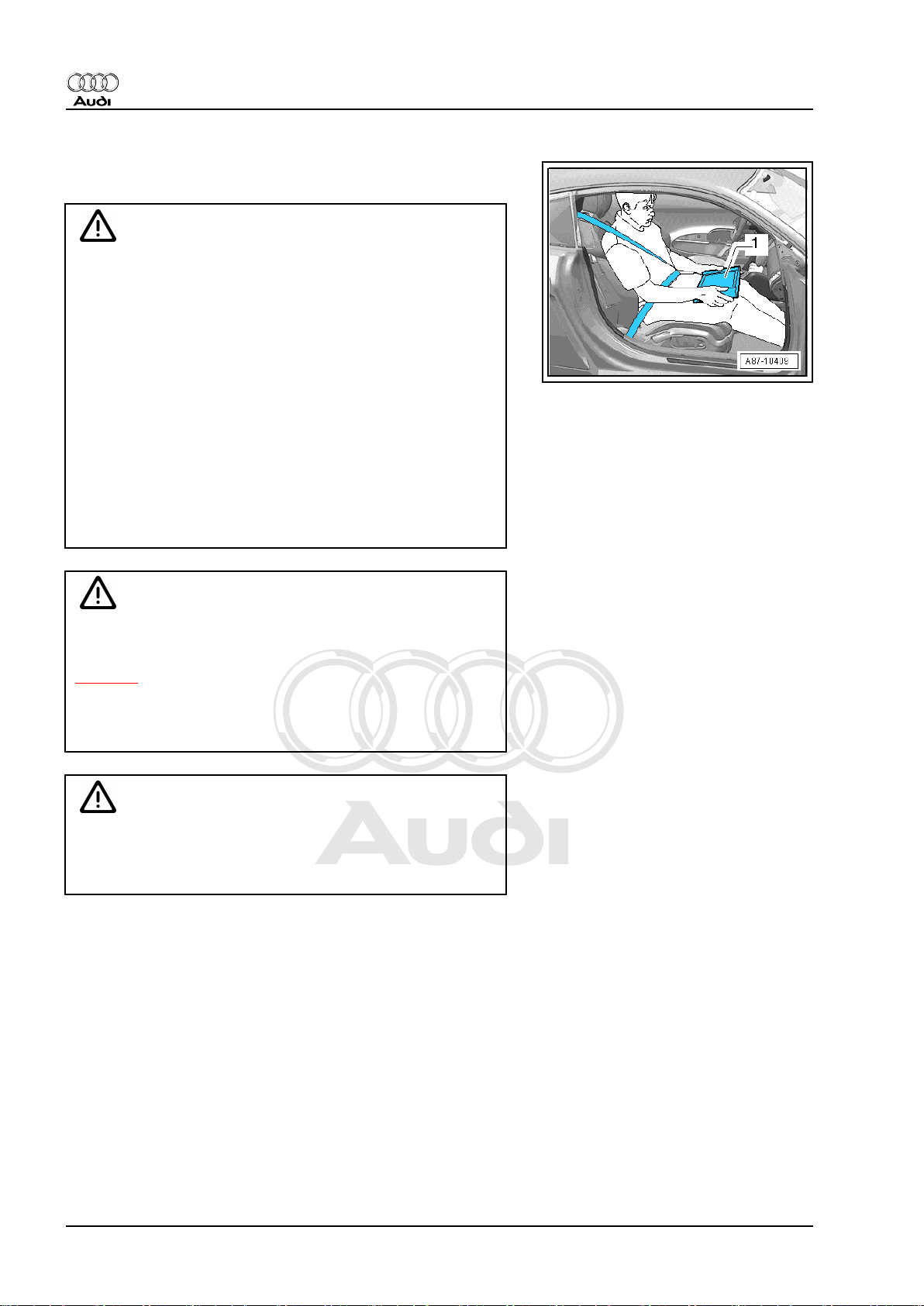
♦ Move the passenger's seat back as far as it will go.
♦ Use only vehicle diagnosis and service information sys‐
tem -VAS 5052 A- or diagnosis system -VAS 5053- .
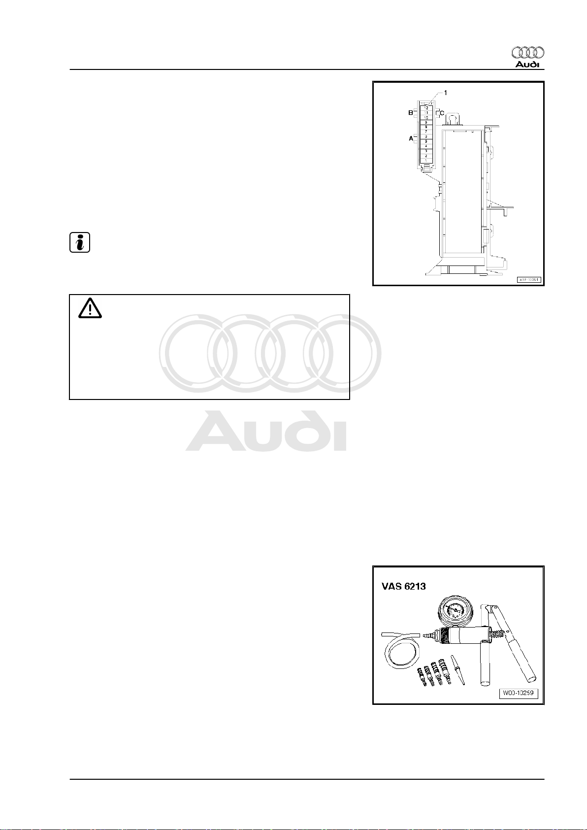
♦ The test equipment -1- must rest flat on the passenger's
thighs (as shown in illustration) and must be operated by
the passenger.
WARNING
The fuel system is pressurised. The fuel pressure in the highpressure part of the injection system must be reduced to a
residual pressure prior to opening; for procedure see
⇒ page 4 .
The connection must be opened immediately after reducing
the pressure; wrap a cloth around the connection and allow the
residual pressure (approx. 6 bar) to dissipate.
Caution
To prevent damage to the electronic components when dis‐
connecting the battery:
♦ Observe notes on procedure for disconnecting the battery.
– Disconnect battery ⇒ Rep. Gr. 27 .
To prevent injuries to persons and/or damage to the fuel injection
and ignition system, the following must be noted:
2 Rep. Gr.24 - Mixture preparation - injection
Page 7
Protected by copyright. Copying for private or commercial purposes, in part or in whole, is not
permitted unless authorised by AUDI AG. AUDI AG does not guarantee or accept any liability
with respect to the correctness of information in this document. Copyright by AUDI AG.
Audi TT 2007 ➤
Direct petrol injection and ignition system (4-cyl. 1.8 ltr., 2.0 ltr. 4-valve turbo with timing chain) - Edition
06.2010
♦ For safety reasons, the battery must be disconnected before
opening the fuel system to prevent the fuel pump from being
activated by the contact switch on the driver's door.
♦ Persons wearing a cardiac pacemaker must at all times main‐
tain a safe distance from high-voltage components such as the
ignition system and gas-discharge headlights.
♦ Do not open any fuel line connections while the engine is run‐
ning.
♦ Always switch off the ignition before connecting or discon‐
necting injection or ignition system wiring or tester cables.
♦ If engine is to be operated at cranking speed without it starting
(e.g. compression test), unplug connectors from ignition coils
and remove fuse for electric fuel pump.
♦ Certain tests may lead to a fault being detected by the control
unit and stored. The event memory should therefore be inter‐
rogated and (if necessary) erased after completing the tests
and any repair work that may be required.
♦ If the event memory has been erased, you must generate the
readiness code again.
♦ Always switch off the ignition before cleaning the engine.
♦ If the engine has to be operated at the starting speed without
actually starting (e.g. to test compression pressure), detach
the four connectors from the ignition coils using assembly tool
-T40039- ⇒ page 84 . Also remove fuse for fuel pump control
unit -J538- .
Note
♦
The fuse is located in the fuse holder in the luggage compart‐
ment (right-side).
♦
Removing the fuse will interrupt the voltage supply “termi‐
nal 30” for the fuel pump control unit -J538- . ⇒ Current flow
diagrams, Electrical fault finding and Fitting locations
1.3 Safety precautions for vehicles with start/stop system
WARNING
Risk of injury due to automatic engine start on vehicles with
start/stop system.
♦ On vehicles with activated start/stop system (this is indi‐
cated by a message in the instrument cluster display), the
engine may start automatically on demand.
♦ Therefore it is important to ensure that the start/stop sys‐
tem is deactivated when performing repairs (switch off
ignition, if required switch on ignition again).
1.4 Rules for cleanliness and instructions for working on fuel system
Even small amounts of dirt can cause faults in the injection sys‐
tem. When working on the fuel supply/injection system, pay care‐
ful attention to the following basic rules:
1. Safety precautions and rules for cleanliness 3
Page 8
Protected by copyright. Copying for private or commercial purposes, in part or in whole, is not
permitted unless authorised by AUDI AG. AUDI AG does not guarantee or accept any liability
with respect to the correctness of information in this document. Copyright by AUDI AG.
Audi TT 2007 ➤
Direct petrol injection and ignition system (4-cyl. 1.8 ltr., 2.0 ltr. 4-valve turbo with timing chain) - Edition
06.2010
♦ Carefully clean connection points and the surrounding area
with engine cleaner or brake cleaner and dry thoroughly before
opening.
♦ Plug open lines and connections with suitable protective caps
immediately.
♦ Place parts that have been removed on a clean surface and
cover them over. Do not use fluffy cloths.
♦ Only install clean components; replacement parts should only
be unpacked immediately prior to installation. Do not use parts
that have been previously unpacked and stored away loose
(e.g. in toolboxes, etc.).
♦ When the system is open: Do not work with compressed air.
Do not move the vehicle unless absolutely necessary.
1.5 Important: Required procedure prior to opening high-pressure injection system
Caution
The injection system consists of a high-pressure section (max‐
imum approx. 150 bar) and a low-pressure section (approx. 7
bar).
Prior to opening the high-pressure section (e.g. when removing
the high-pressure pump, fuel rail, injectors, fuel pipes, etc.) the
fuel pressure in the high-pressure section must be reduced.
The procedure is described below.
Reducing fuel pressure in high-pressure section
– Connect a vehicle diagnostic tester.
– Start engine and run at idling speed.
– Select “Engine electronics” in vehicle self-diagnosis.
– Then select function read “Measured values”.
– Select measured value block 140.
– With engine idling the fuel pressure is displayed in zone 3.
♦ Specification: between 35 and 45 bar
– The fuse is located in the fuse holder in the luggage compart‐
ment (right-side).
4 Rep. Gr.24 - Mixture preparation - injection
Page 9
Protected by copyright. Copying for private or commercial purposes, in part or in whole, is not
permitted unless authorised by AUDI AG. AUDI AG does not guarantee or accept any liability
with respect to the correctness of information in this document. Copyright by AUDI AG.
Audi TT 2007 ➤
Direct petrol injection and ignition system (4-cyl. 1.8 ltr., 2.0 ltr. 4-valve turbo with timing chain) - Edition
06.2010
– Remove luggage compartment trim (rear right) ⇒ Rep. Gr.
70 .
– With engine idling, pull out fuse for fuel pump control unit -
J538- ⇒ Current flow diagrams, Electrical fault finding and
Fitting locations.
– Observe fuel pressure displayed on tester.
• The fuel pressure will decrease very quickly because the me‐
chanical high-pressure pump is no longer being supplied with
fuel by the fuel system pressurisation pump -G6- .
– Switch off ignition as soon as fuel pressure has dropped to
approx. 8 bar.
Note
Fuel pressure must not fall below 6 bar, otherwise the engine will
stall (this could damage the catalytic converter).
WARNING
The fuel lines are still filled with fuel, however the fuel is no
longer under high pressure. Wear safety goggles and protec‐
tive clothing when opening the fuel system to avoid possible
injury and skin contact.
Before opening the high-pressure section, wrap a cloth around
the connection.
– The high-pressure system must be opened “immediately” after
reducing the fuel pressure; wrap a clean cloth around the con‐
nection. Catch the escaping fuel.
The following operations must be performed after completing re‐
pair work:
– Refit fuse.
– Erase event memory and generate readiness code in engine
control unit in “Guided Functions” mode.
1.6 Checking vacuum system
Special tools and workshop equipment required
♦ Hand vacuum pump -VAS 6213-
Procedure
– Check all vacuum lines in the complete vacuum system for:
♦ Cracks
1. Safety precautions and rules for cleanliness 5
Page 10

Protected by copyright. Copying for private or commercial purposes, in part or in whole, is not
permitted unless authorised by AUDI AG. AUDI AG does not guarantee or accept any liability
with respect to the correctness of information in this document. Copyright by AUDI AG.
Audi TT 2007 ➤
Direct petrol injection and ignition system (4-cyl. 1.8 ltr., 2.0 ltr. 4-valve turbo with timing chain) - Edition
06.2010
♦ Traces of animal bites
♦ Kinked or crushed lines
♦ Lines porous or leaking
– Check vacuum line to solenoid valve and from solenoid valve
to corresponding component.
– If an entry is stored in the event memory, check the vacuum
lines leading to the corresponding component and also check
the remaining vacuum lines leading to other components.
– If it is not possible to build up pressure with the hand vacuum
pump -VAS 6213- or if the pressure drops again immediately,
check the hand vacuum pump and connecting hoses for leaks.
6 Rep. Gr.24 - Mixture preparation - injection
Page 11
Protected by copyright. Copying for private or commercial purposes, in part or in whole, is not
permitted unless authorised by AUDI AG. AUDI AG does not guarantee or accept any liability
with respect to the correctness of information in this document. Copyright by AUDI AG.
Audi TT 2007 ➤
Direct petrol injection and ignition system (4-cyl. 1.8 ltr., 2.0 ltr. 4-valve turbo with timing chain) - Edition
06.2010
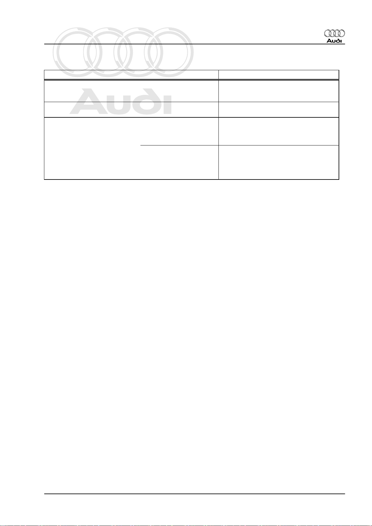
2 Technical data
Engine data 1.8 ltr. and 2.0 ltr. turbo FSI engine
Idling speed is not adjustable; con‐
trolled by the idling speed stabili‐
sation
Maximum rpm governed by deac‐
tivation of fuel injectors
Fuel pressure Initial fuel pressure up to
high-pressure pump (gen‐
erated by electric fuel pump
Pressure in high-pressure
fuel circuit (generated by
mechanical single-plunger
pump) at a coolant temper‐
ature of approx. 85°C.
in fuel tank)
640 ... 800 rpm
6500 rpm
3.0 to 7.0 bar (identical for all operating
conditions)
approx. 40 bar at idling speed
approx. 150 bar in certain parts of operating
range.
2. Technical data 7
Page 12
Protected by copyright. Copying for private or commercial purposes, in part or in whole, is not
permitted unless authorised by AUDI AG. AUDI AG does not guarantee or accept any liability
with respect to the correctness of information in this document. Copyright by AUDI AG.
Audi TT 2007 ➤
Direct petrol injection and ignition system (4-cyl. 1.8 ltr., 2.0 ltr. 4-valve turbo with timing chain) - Edition
06.2010
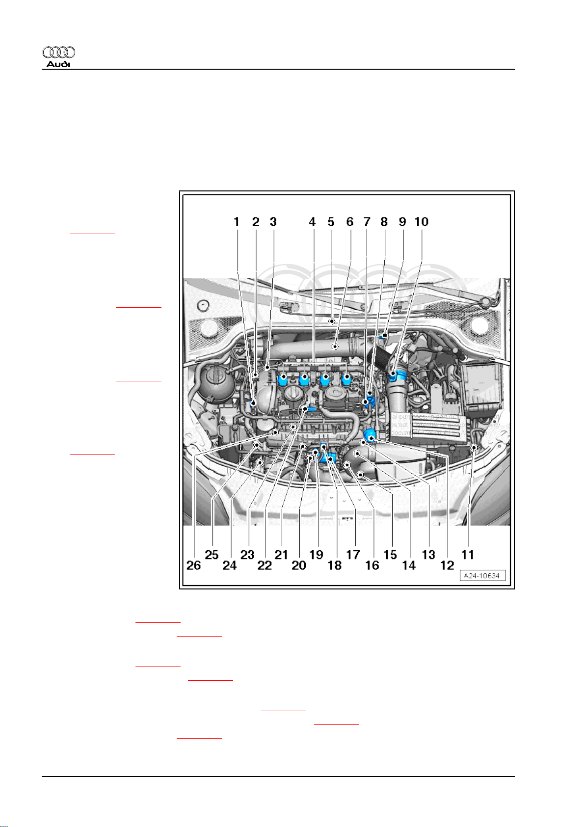
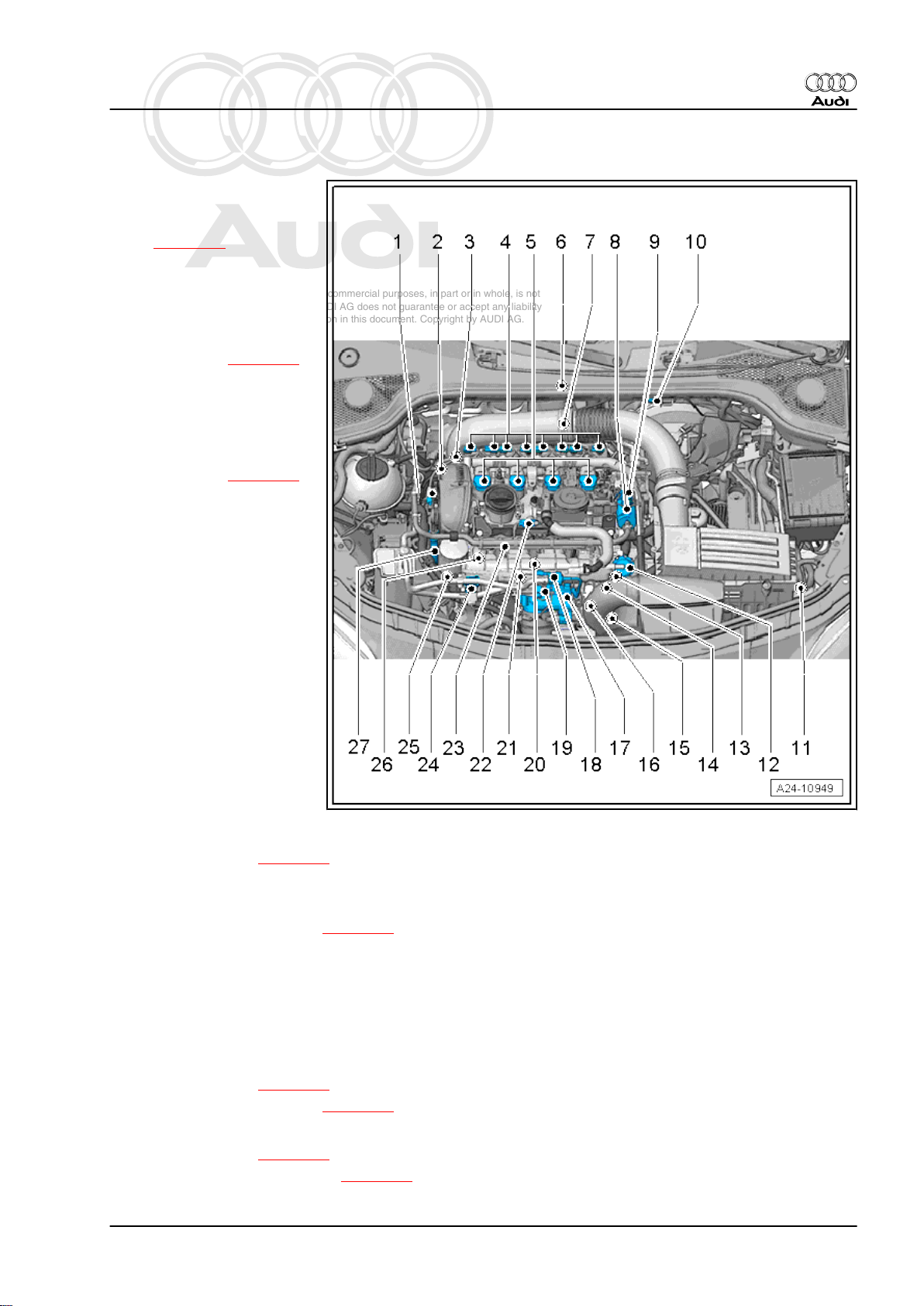
3 Overviews - fitting locations
3.1 Overview - fitting locations (engine co‐
des CDAA, CCZA and CCTA)
Components A to K are not shown in the overview.
1 - Camshaft control valve 1 N205-
❑ Fitting location
⇒ page 14
❑ Removing and installing
⇒ Rep. Gr. 15
2 - Charge pressure control
solenoid valve -N75-
❑ Located directly on tur‐
bocharger ⇒ page 17
❑ Removing and installing
⇒ Rep. Gr. 21
3 - Turbocharger air recircula‐
tion valve -N249-
❑ Located directly on tur‐
bocharger ⇒ page 17
❑ Removing and installing
⇒ Rep. Gr. 21
4 - Ignition coils with output
stages
❑ Removing and installing
⇒ page 84
❑ Ignition coil 1 with output
stage -N70-
❑ Ignition coil 2 with output
stage -N127-
❑ Ignition coil 3 with output
stage -N291-
❑ Ignition coil 4 with output
stage -N292-
❑ Puller -T40039- is re‐
quired for removing igni‐
tion coils from cylinder
head.
5 - Engine control unit -J623-
❑ Fitting location ⇒ page 11
❑ Removing and installing ⇒ page 77
6 - Lambda probe -G39- and Lambda probe heater -Z19-
❑ Fitting location ⇒ page 17
❑ Lambda probes - overview ⇒ page 71
7 - High-pressure pump
❑ Fitting location (engine code CDAA, 1.8 ltr.) ⇒ page 12
❑ Fitting location (engine codes CCZA and CCTA, 2.0 ltr.) ⇒ page 12
❑ Removing and installing ⇒ page 50
8 Rep. Gr.24 - Mixture preparation - injection
Page 13

Protected by copyright. Copying for private or commercial purposes, in part or in whole, is not
permitted unless authorised by AUDI AG. AUDI AG does not guarantee or accept any liability
with respect to the correctness of information in this document. Copyright by AUDI AG.
Audi TT 2007 ➤
Direct petrol injection and ignition system (4-cyl. 1.8 ltr., 2.0 ltr. 4-valve turbo with timing chain) - Edition
06.2010
8 - Fuel pressure regulating valve -N276-
❑ Fitting location (engine code CDAA, 1.8 ltr.) ⇒ page 12
❑ Fitting location (engine codes CCZA and CCTA, 2.0 ltr.) ⇒ page 12
9 - Electrical connector for Lambda probe -G39- and Lambda probe heater -Z19-
❑ Fitting location ⇒ page 16
10 - Air mass meter -G70- and intake air temperature sender 2 -G299-
❑ Removing and installing ⇒ page 65
11 - Radiator outlet coolant temperature sender -G83-
❑ Fitting location ⇒ page 16
12 - Vacuum unit for air flow control flaps (intake manifold flaps)
❑ Fitting location ⇒ page 13
13 - Intake manifold flap valve -N316-
❑ Fitting location ⇒ page 13
14 - Engine speed sender -G28-
❑ Fitting location ⇒ page 15
❑ Removing and installing ⇒ page 85
❑ 4.5 Nm
15 - Charge pressure sender -G31-
❑ Fitting location ⇒ page 16
16 - Electrical connectors
❑ From knock sensor 1 -G61- , fitting location ⇒ page 15
❑ From Hall sender -G40- , fitting location ⇒ page 15
❑ For injectors, fitting location ⇒ page 15
17 - Throttle valve module -J338- , throttle valve drive for electric throttle -G186-
❑ Throttle valve drive angle sender 1 for electric throttle -G187- and throttle valve drive angle sender 2 for
electric throttle -G188-
❑ After throttle valve module -J338- has been renewed, it must be re-adapted to engine control unit -J623- ,
see vehicle diagnostic, testing and information system -VAS 5051B-
18 - Activated charcoal filter solenoid valve 1 -N80-
❑ Fitting location ⇒ page 13
19 - Intake air temperature sender -G42-
20 - Knock sensor 1 -G61-
❑ Fitting location ⇒ page 13
❑ 20 Nm
❑ Removing and installing ⇒ page 85
21 - Coolant temperature sender -G62-
❑ Fitting location ⇒ page 15
❑ Removing and installing ⇒ Rep. Gr. 19
22 - Hall sender -G40- (camshaft position sensor)
23 - Fuel pressure sender -G247-
❑ 27 Nm
❑ Fitting location ⇒ page 13
❑ Removing and installing ⇒ page 59
24 - Valve for oil pressure control -N428-
❑ Fitting location ⇒ page 14
❑ Removing and installing ⇒ Rep. Gr. 17
3. Overviews - fitting locations 9
Page 14

Protected by copyright. Copying for private or commercial purposes, in part or in whole, is not
permitted unless authorised by AUDI AG. AUDI AG does not guarantee or accept any liability
with respect to the correctness of information in this document. Copyright by AUDI AG.
Audi TT 2007 ➤
Direct petrol injection and ignition system (4-cyl. 1.8 ltr., 2.0 ltr. 4-valve turbo with timing chain) - Edition
06.2010
25 - Oil pressure switch
❑ Oil pressure switch for reduced oil pressure -F378❑ Oil pressure switch -F22❑ Fitting location ⇒ page 14
❑ Removing and installing ⇒ Rep. Gr. 17
26 - Intake manifold flap potentiometer -G336-
❑ Fitting location ⇒ page 14
A - Diagnostic connector
❑ In driver's knee restraint
B - Fuel pump control unit -J538-
❑ Fitting location ⇒ page 11
C - Brake light switch - F- and brake pedal switch -F63-
❑ Fitting location ⇒ page 12
❑ Removing and installing ⇒ Rep. Gr. 45
D - Clutch position sender -G476-
❑ Only fitted on vehicles with manual gearbox
❑ Fitting location ⇒ page 12
❑ Removing and installing, see Power transmission, clutch ⇒ Rep. Gr. 30
E - Accelerator position sender -G79- and accelerator position sender 2 -G185-
❑ Fitting location ⇒ page 11
❑ On accelerator pedal (both senders are accommodated in one housing)
❑ If accelerator pedal module or engine control unit is renewed, kick-down function must be adapted on
vehicles with automatic gearbox
❑ Removing and installing ⇒ Rep. Gr. 20
F - Radiator fan control unit -J293-
❑ Fitting location ⇒ page 16
G - Injectors
❑ Removing and installing ⇒ page 53
❑ Injector, cylinder 1 -N30❑ Injector, cylinder 2 -N31❑ Injector, cylinder 3 -N32❑ Injector, cylinder 4 -N33-
H - Continued coolant circulation pump -V51-
❑ Fitting location ⇒ page 18
❑ Removing and installing ⇒ Rep. Gr. 19
I - Lambda probe after catalytic converter -G130- and Lambda probe heater 1 after catalytic converter -Z29-
❑ Fitting location ⇒ page 17
❑ Lambda probes - overview ⇒ page 71
J - Electrical connector for Lambda probe after catalytic converter -G130- and Lambda probe 1 heater after
catalytic converter -Z29-
❑ Fitting location ⇒ page 17
K - Relay and fuse holder in electronics box
❑ Relay and fuse assignment see ⇒ Current flow diagrams, Electrical fault finding and Fitting locations
10 Rep. Gr.24 - Mixture preparation - injection
Page 15
Protected by copyright. Copying for private or commercial purposes, in part or in whole, is not
permitted unless authorised by AUDI AG. AUDI AG does not guarantee or accept any liability
with respect to the correctness of information in this document. Copyright by AUDI AG.
Audi TT 2007 ➤
Direct petrol injection and ignition system (4-cyl. 1.8 ltr., 2.0 ltr. 4-valve turbo with timing chain) - Edition
06.2010
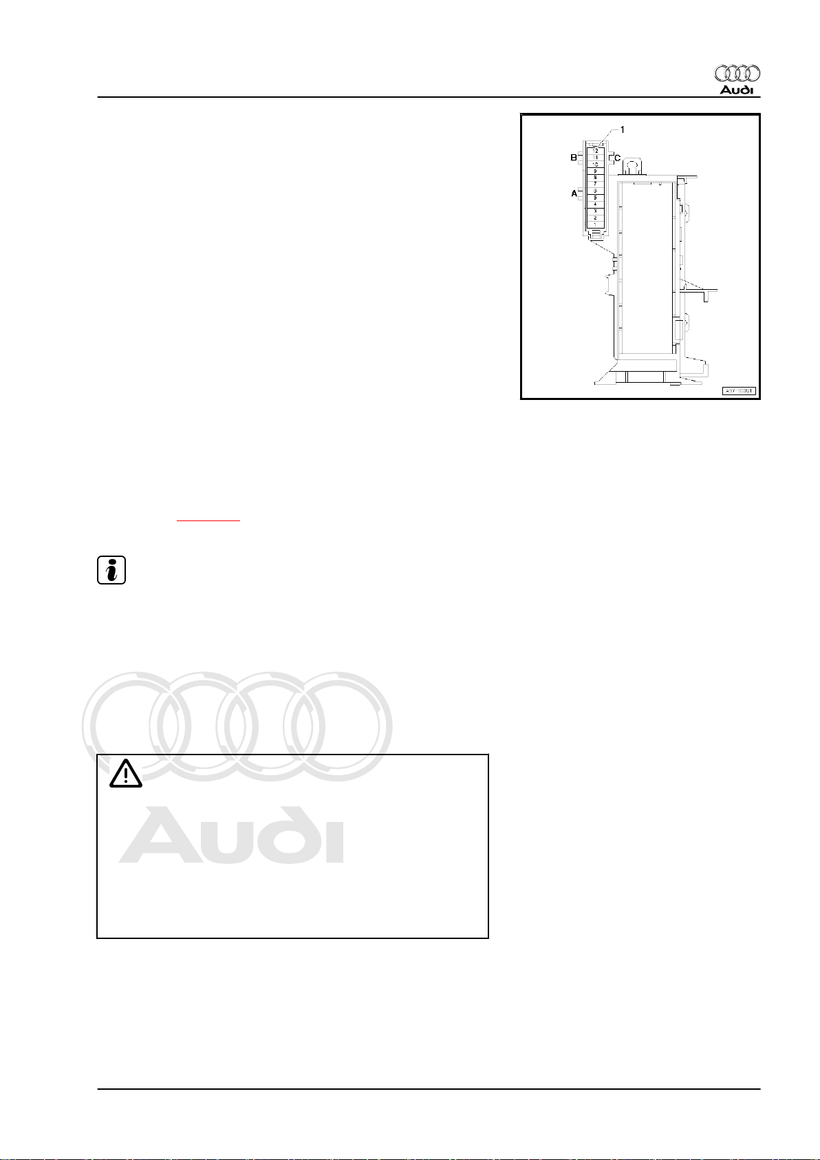
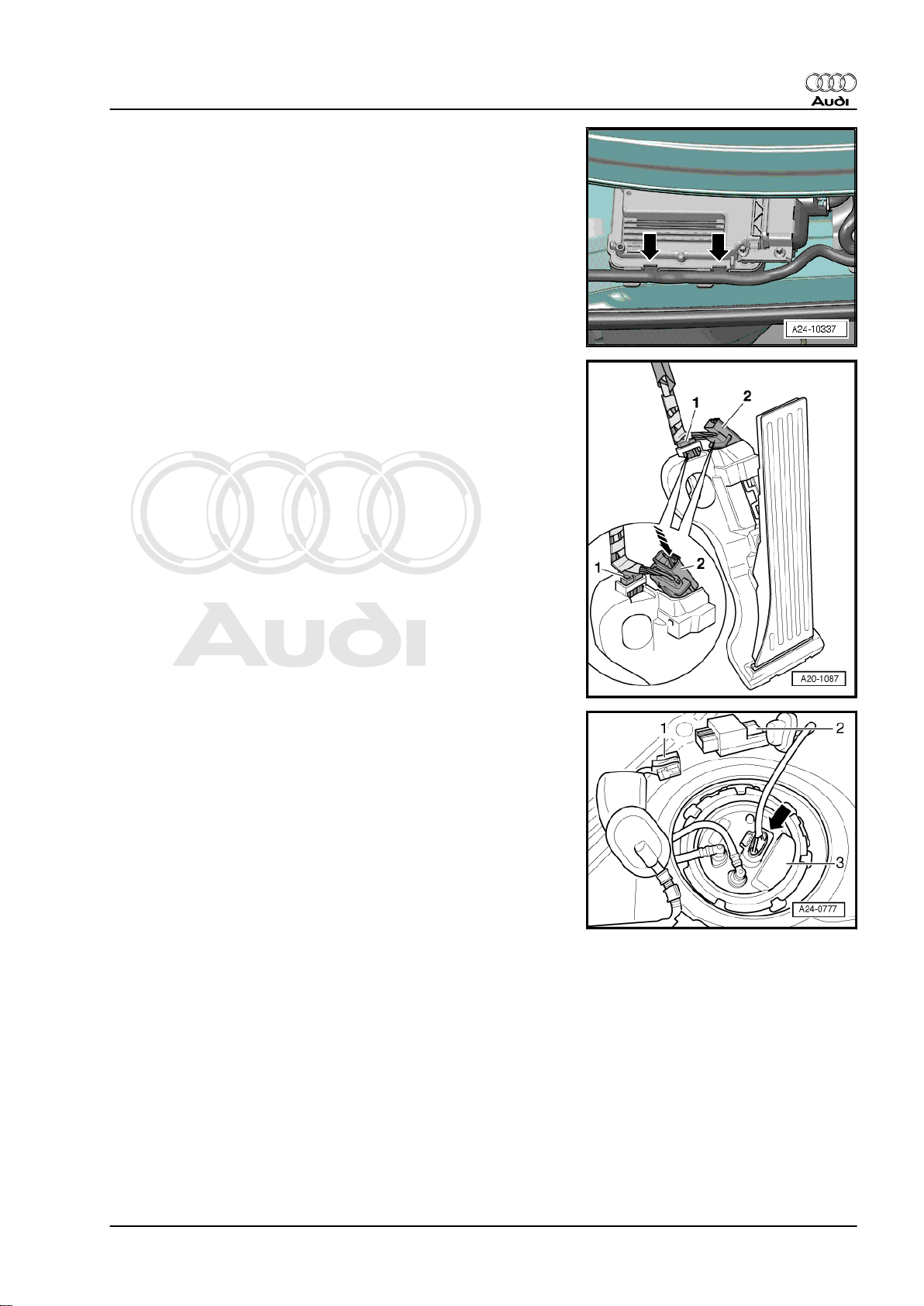
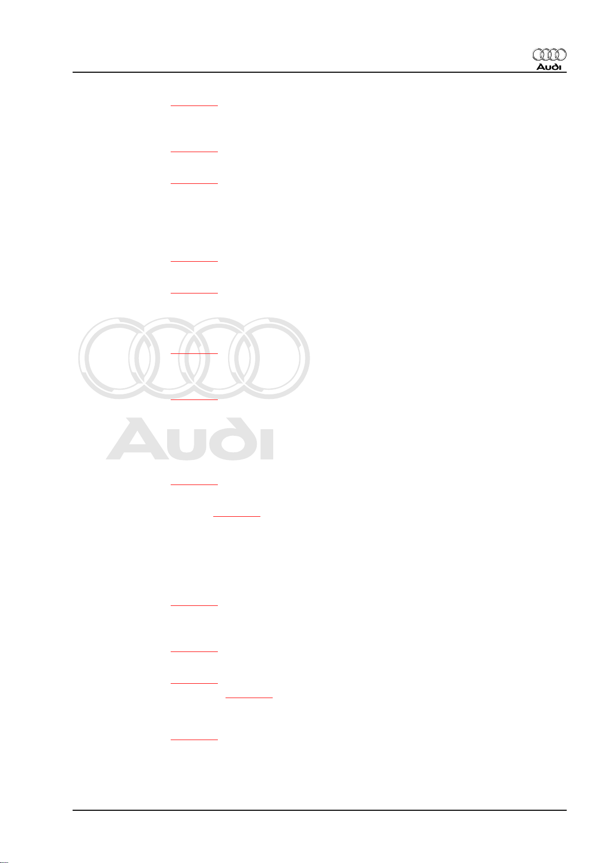
Engine control unit -J623-
Accelerator position sender -G79- and accelerator position send‐
er 2 -G185-
2 - Electrical connector for accelerator pedal module
Removing and installing ⇒ Rep. Gr. 20
Fuel pump control unit -J538- -2-
1 - Connector for fuel pump control unit -J538-
2 - Fuel pump control unit -J538-
3 - Fuel system pressurisation pump -G6-
3. Overviews - fitting locations 11
Page 16
Protected by copyright. Copying for private or commercial purposes, in part or in whole, is not
permitted unless authorised by AUDI AG. AUDI AG does not guarantee or accept any liability
with respect to the correctness of information in this document. Copyright by AUDI AG.
Audi TT 2007 ➤
Direct petrol injection and ignition system (4-cyl. 1.8 ltr., 2.0 ltr. 4-valve turbo with timing chain) - Edition
06.2010
Clutch position sender -G476-
Removing and installing ⇒ Rep. Gr. 30
Brake light switch -F- and brake pedal switch -F63-
High-pressure pump -2-
1 - Fuel pressure regulating valve -N276-
Note
Illustration shows pump of engine code CDAA, 1.8 ltr.
High-pressure pump -2-
1 - Fuel pressure regulating valve -N276-
Note
Illustration shows pump of engine codes CCZA and CCTA, 2.0
ltr.
12 Rep. Gr.24 - Mixture preparation - injection
Page 17
Protected by copyright. Copying for private or commercial purposes, in part or in whole, is not
permitted unless authorised by AUDI AG. AUDI AG does not guarantee or accept any liability
with respect to the correctness of information in this document. Copyright by AUDI AG.
Audi TT 2007 ➤
Direct petrol injection and ignition system (4-cyl. 1.8 ltr., 2.0 ltr. 4-valve turbo with timing chain) - Edition
06.2010
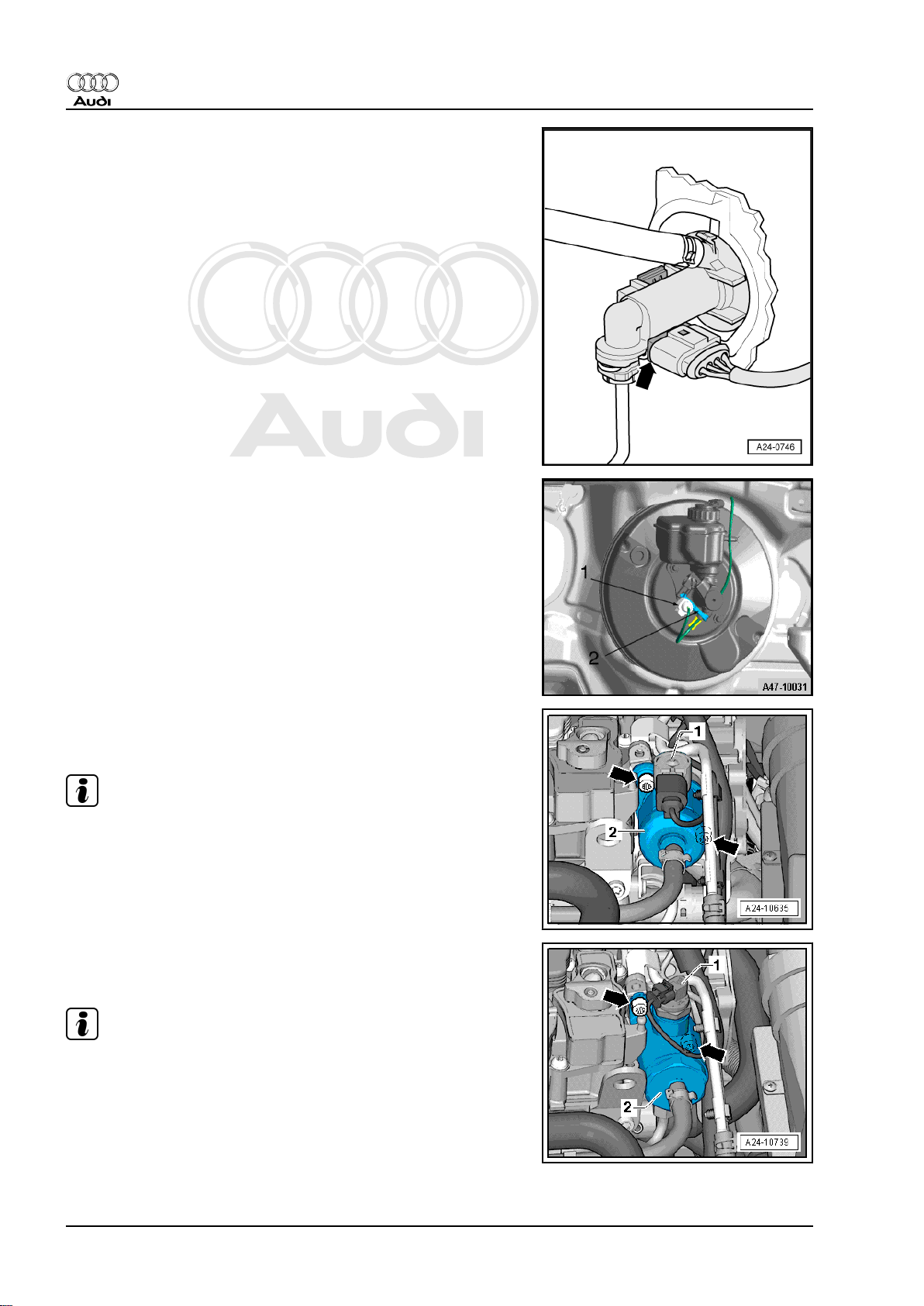
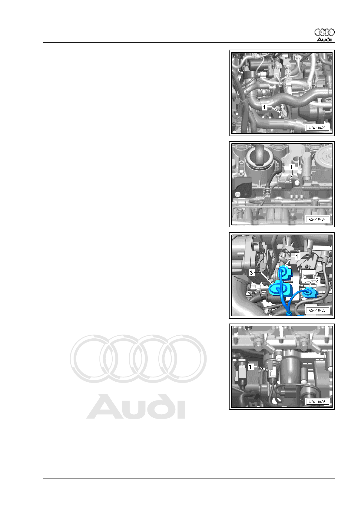
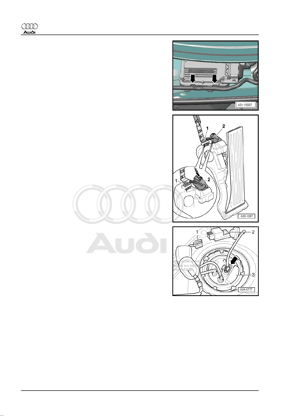
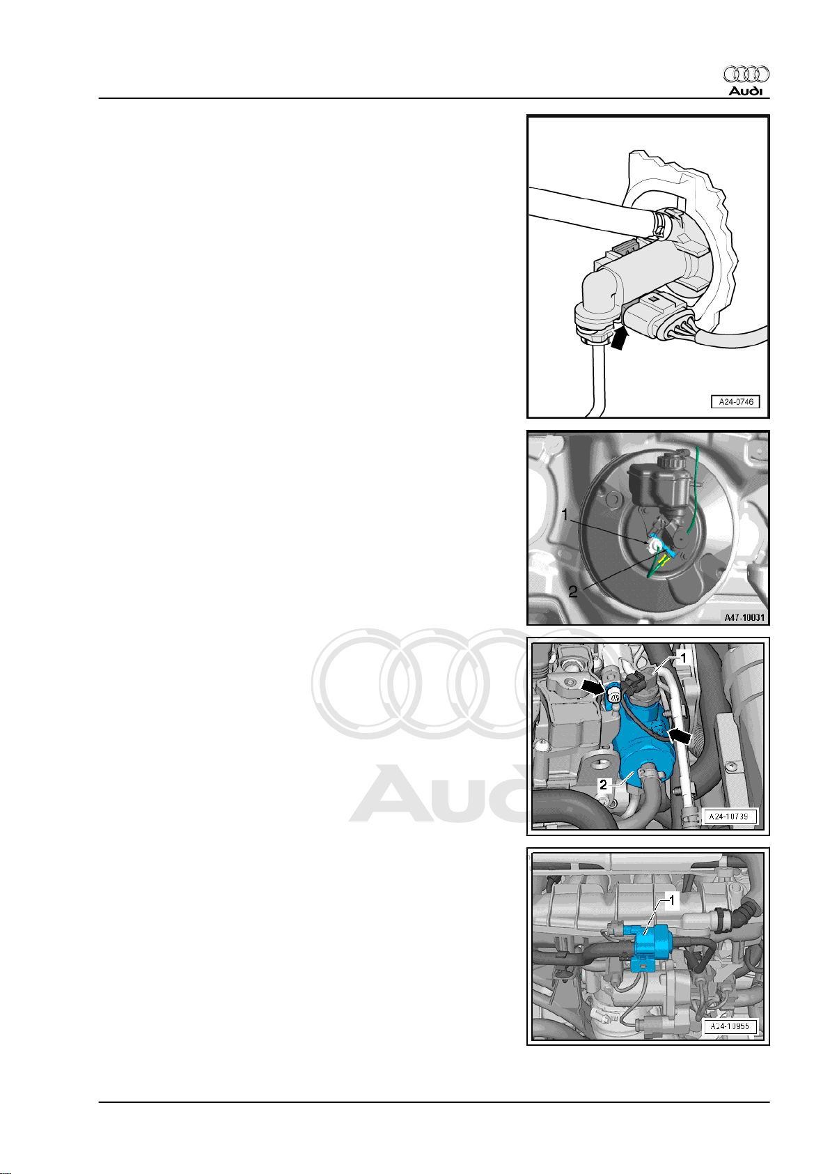
Activated charcoal filter solenoid valve 1 -N80- -1-
Fitting location of knock sensor 1 -G61-
1 - Electrical connector for knock sensor 1 -G61-
2 - Knock sensor 1 -G61-
Fitting location: below intake manifold and coolant pump
Intake manifold flap valve -N316- -2-
1 - Vacuum unit for intake manifold flaps
Note
Intake manifold flaps are the same as air flow control flaps.
Fuel pressure sender -G247- -1-
Removing and installing ⇒ page 59
3. Overviews - fitting locations 13
Page 18
Protected by copyright. Copying for private or commercial purposes, in part or in whole, is not
permitted unless authorised by AUDI AG. AUDI AG does not guarantee or accept any liability
with respect to the correctness of information in this document. Copyright by AUDI AG.
Audi TT 2007 ➤
Direct petrol injection and ignition system (4-cyl. 1.8 ltr., 2.0 ltr. 4-valve turbo with timing chain) - Edition
06.2010
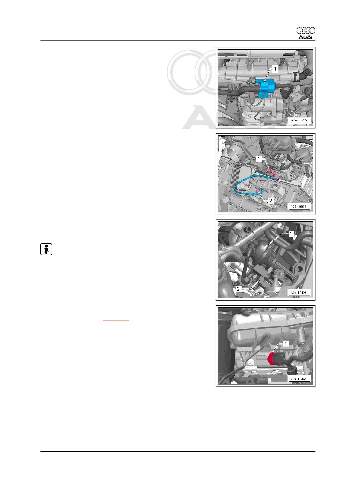
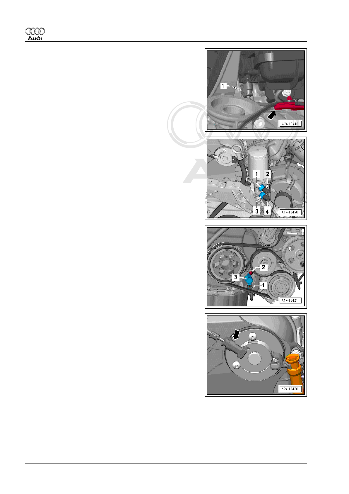
Intake manifold flap potentiometer -G336- -1-
Oil pressure switch
1 - Oil pressure switch for reduced oil pressure -F378-
2 - Electrical connector for oil pressure switch for reduced oil
pressure -F378-
3 - Oil pressure switch -F22-
4 - Electrical connector for oil pressure switch -F22-
Valve for oil pressure control -N428- -3-
Camshaft control valve 1 -N205- -arrow-
Removing and installing ⇒ Rep. Gr. 45
14 Rep. Gr.24 - Mixture preparation - injection
Page 19
Protected by copyright. Copying for private or commercial purposes, in part or in whole, is not
permitted unless authorised by AUDI AG. AUDI AG does not guarantee or accept any liability
with respect to the correctness of information in this document. Copyright by AUDI AG.
Audi TT 2007 ➤
Direct petrol injection and ignition system (4-cyl. 1.8 ltr., 2.0 ltr. 4-valve turbo with timing chain) - Edition
06.2010
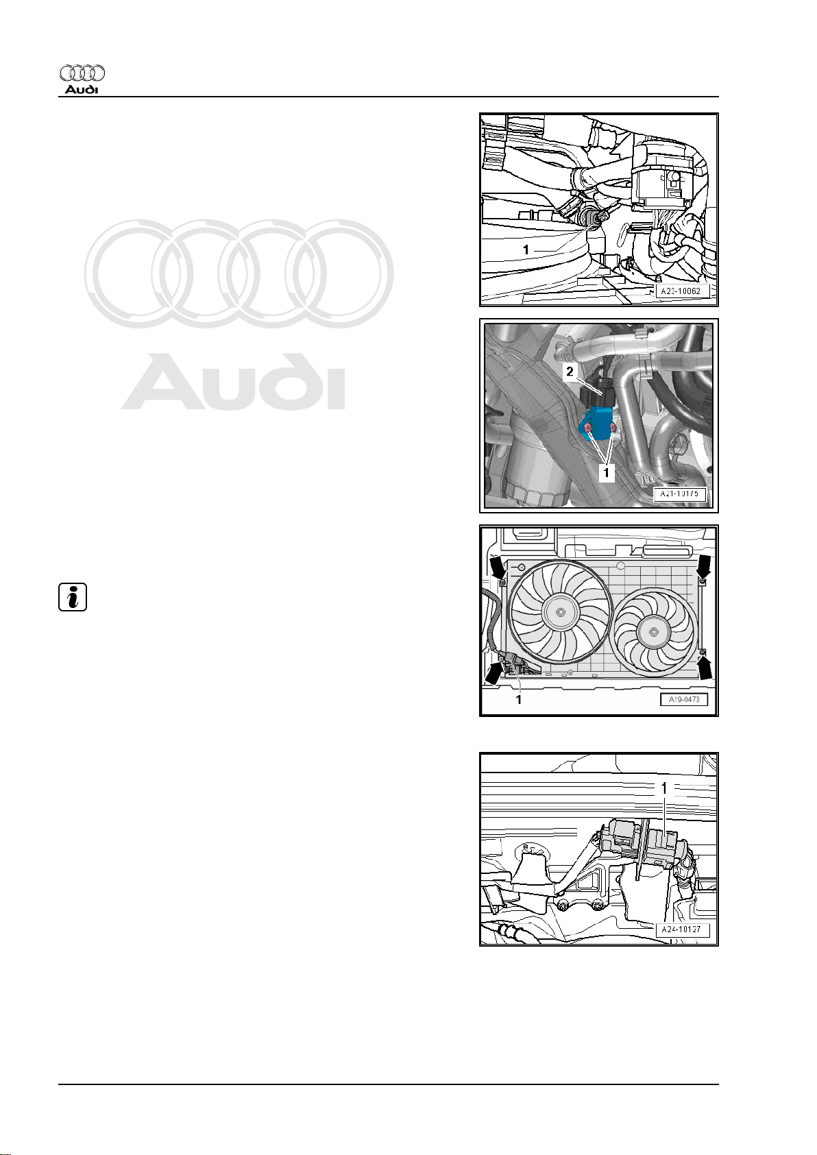
Engine speed sender -G28- -1-
Hall sender -G40- -1-
Electrical connectors
1 - From Hall sender -G40- and intake manifold flap potentiometer
-G336-
2 - From knock sensor 1 -G61-
3 - 8-pin connector for injectors
Coolant temperature sender -G62- -1-
Fitting location: below intake manifold in coolant pump
3. Overviews - fitting locations 15
Page 20
Protected by copyright. Copying for private or commercial purposes, in part or in whole, is not
permitted unless authorised by AUDI AG. AUDI AG does not guarantee or accept any liability
with respect to the correctness of information in this document. Copyright by AUDI AG.
Audi TT 2007 ➤
Direct petrol injection and ignition system (4-cyl. 1.8 ltr., 2.0 ltr. 4-valve turbo with timing chain) - Edition
06.2010
Radiator outlet coolant temperature sender -G83- -1-
Charge pressure sender -G31- -2-
Radiator fan control unit -J293-
1 - Connector for radiator fan control unit -J293-
Note
♦
The radiator fan control unit -J293- is integrated into the radi‐
ator fan -V7- .
♦
The fan shown in the illustration on the left is the radiator fan
-V7- .
♦
The fan shown in the illustration on the right is the radiator fan
on right of radiator -V35- .
Electrical connector
1 - For Lambda probe -G39- and Lambda probe heater -Z19-
16 Rep. Gr.24 - Mixture preparation - injection
Page 21
Protected by copyright. Copying for private or commercial purposes, in part or in whole, is not
permitted unless authorised by AUDI AG. AUDI AG does not guarantee or accept any liability
with respect to the correctness of information in this document. Copyright by AUDI AG.
Audi TT 2007 ➤
Direct petrol injection and ignition system (4-cyl. 1.8 ltr., 2.0 ltr. 4-valve turbo with timing chain) - Edition
06.2010
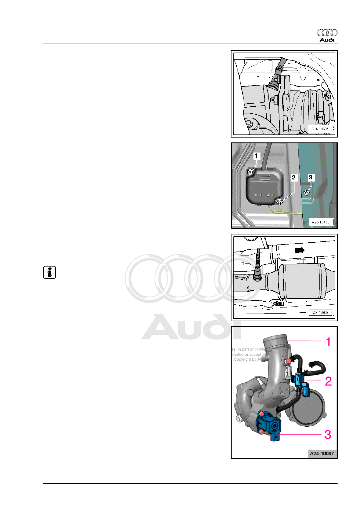
Fitting location of Lambda probe
1 - Lambda probe -G39- and Lambda probe heater -Z19-
Electrical connector (behind cover) for Lambda probe after cata‐
lytic converter -G130- and Lambda probe 1 heater after catalytic
converter -Z29-
Fitting location of Lambda probe
1 - Lambda probe after catalytic converter -G130- with Lambda
probe 1 heater after catalytic converter -Z29-
Note
The arrow in the illustration points in the direction of travel.
Components on turbocharger
1 - Removing and installing turbocharger ⇒ Rep. Gr. 21
2 - Tighten charge pressure control solenoid valve -N75- to 3 Nm
3 - Tighten turbocharger air recirculation valve -N249- to 7 Nm
(note installation position, refer to next illustration)
3. Overviews - fitting locations 17
Page 22
Protected by copyright. Copying for private or commercial purposes, in part or in whole, is not
permitted unless authorised by AUDI AG. AUDI AG does not guarantee or accept any liability
with respect to the correctness of information in this document. Copyright by AUDI AG.
Audi TT 2007 ➤
Direct petrol injection and ignition system (4-cyl. 1.8 ltr., 2.0 ltr. 4-valve turbo with timing chain) - Edition
06.2010
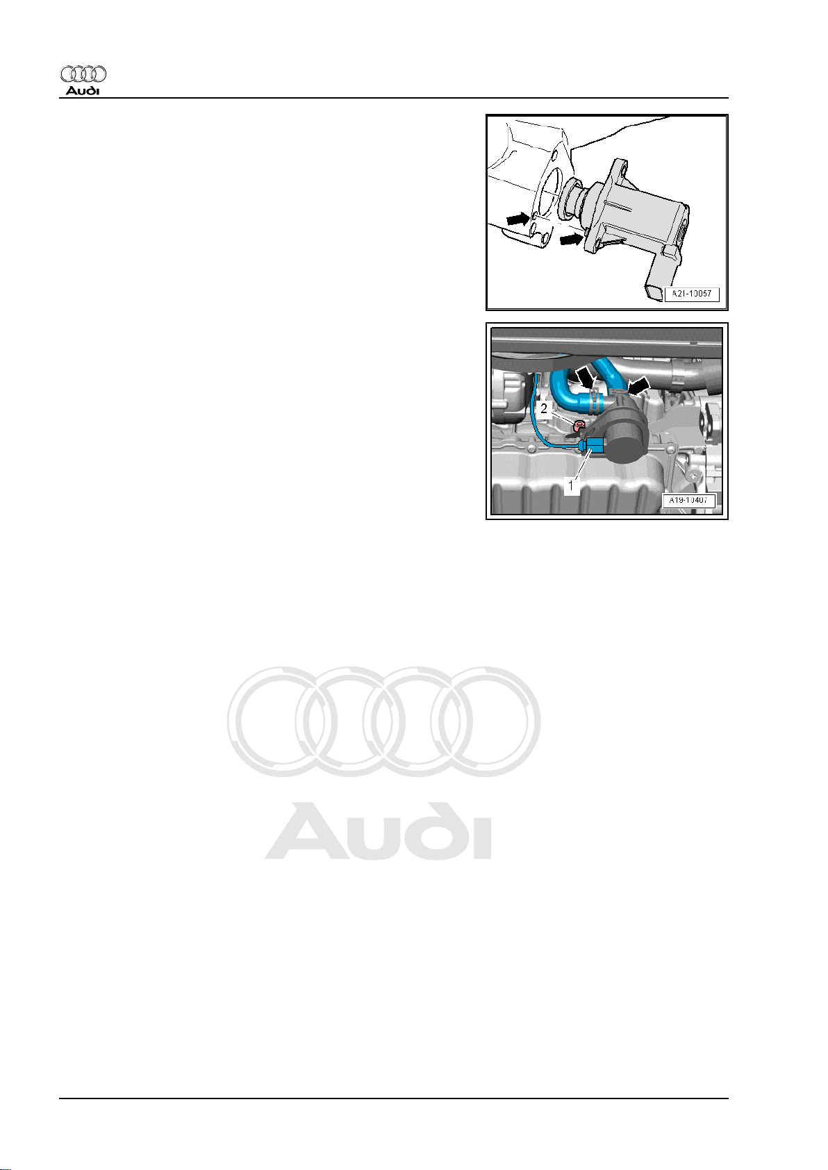
Pay attention to installation position of turbocharger air recircula‐
tion valve -N249-
Continued coolant circulation pump -V51-
Removing and installing ⇒ Rep. Gr. 19
18 Rep. Gr.24 - Mixture preparation - injection
Page 23
Protected by copyright. Copying for private or commercial purposes, in part or in whole, is not
permitted unless authorised by AUDI AG. AUDI AG does not guarantee or accept any liability
with respect to the correctness of information in this document. Copyright by AUDI AG.
Audi TT 2007 ➤
Direct petrol injection and ignition system (4-cyl. 1.8 ltr., 2.0 ltr. 4-valve turbo with timing chain) - Edition
06.2010
3.2 Overview - fitting locations (engine codes CESA and CETA)
1 - Camshaft control valve 1 N205-
❑ Fitting location
⇒ page 25
❑ Removing and installing
⇒ Rep. Gr. 15
2 - Charge pressure control
solenoid valve -N75-
❑ Located directly on tur‐
bocharger ⇒ page 29
❑ Removing and installing
⇒ Rep. Gr. 21
3 - Turbocharger air recircula‐
tion valve -N249-
❑ Located directly on tur‐
bocharger ⇒ page 29
❑ Removing and installing
⇒ Rep. Gr. 21
4 - Actuators for camshaft ad‐
justment
❑ Actuator 1 for camshaft
adjustment -F366-
❑ Actuator 2 for camshaft
adjustment -F367-
❑ Actuator 3 for camshaft
adjustment -F368-
❑ Actuator 4 for camshaft
adjustment -F369-
❑ Actuator 5 for camshaft
adjustment -F370-
❑ Actuator 6 for camshaft
adjustment -F371-
❑ Actuator 7 for camshaft
adjustment -F372-
❑ Actuator 8 for camshaft adjustment -F373❑ Fitting location ⇒ page 26
❑ Removing and installing ⇒ Rep. Gr. 15
5 - Ignition coils with output stages
❑ Removing and installing ⇒ page 84
❑ Ignition coil 1 with output stage -N70❑ Ignition coil 2 with output stage -N127❑ Ignition coil 3 with output stage -N291❑ Ignition coil 4 with output stage -N292❑ Puller -T40039- is required for removing ignition coils from cylinder head.
6 - Engine control unit -J623-
❑ Fitting location ⇒ page 22
❑ Removing and installing ⇒ page 77
7 - Lambda probe -G39- and Lambda probe heater -Z19-
❑ Fitting location ⇒ page 28
❑ Lambda probes - overview ⇒ page 71
3. Overviews - fitting locations 19
Page 24

Protected by copyright. Copying for private or commercial purposes, in part or in whole, is not
permitted unless authorised by AUDI AG. AUDI AG does not guarantee or accept any liability
with respect to the correctness of information in this document. Copyright by AUDI AG.
Audi TT 2007 ➤
Direct petrol injection and ignition system (4-cyl. 1.8 ltr., 2.0 ltr. 4-valve turbo with timing chain) - Edition
06.2010
8 - High-pressure pump
❑ Fitting location ⇒ page 23
❑ Removing and installing ⇒ page 50
9 - Fuel pressure regulating valve -N276-
❑ Fitting location ⇒ page 23
10 - Electrical connector for Lambda probe -G39- and Lambda probe heater -Z19-
❑ Fitting location ⇒ page 28
11 - Radiator outlet coolant temperature sender -G83-
❑ Fitting location ⇒ page 27
12 - Vacuum unit for air flow control flaps (intake manifold flaps)
❑ Fitting location ⇒ page 24
13 - Intake manifold flap valve -N316-
❑ Fitting location ⇒ page 24
14 - Engine speed sender -G28-
❑ Fitting location ⇒ page 26
❑ Removing and installing ⇒ page 85
❑ 4.5 Nm
15 - Charge pressure sender -G31-
❑ Fitting location ⇒ page 27
16 - Electrical connectors
❑ From knock sensor 1 -G61- , fitting location ⇒ page 27
❑ From Hall sender -G40- , fitting location ⇒ page 27
❑ For injectors, fitting location ⇒ page 15
17 - Throttle valve module -J338- , throttle valve drive for electric throttle -G186-
❑ Throttle valve drive angle sender 1 for electric throttle -G187- and throttle valve drive angle sender 2 for
electric throttle -G188-
❑ After throttle valve module -J338- has been renewed, it must be re-adapted to engine control unit -J623-
using a vehicle diagnostic tester
18 - Activated charcoal filter solenoid valve 1 -N80-
❑ Fitting location ⇒ page 23
19 - Intake air temperature sender -G42-
20 - Knock sensor 1 -G61-
❑ Fitting location ⇒ page 24
❑ 20 Nm
❑ Removing and installing ⇒ page 85
21 - Coolant temperature sender -G62-
❑ Fitting location ⇒ page 27
❑ Removing and installing ⇒ Rep. Gr. 19
22 - Hall sender -G40- (camshaft position sensor)
23 - Fuel pressure sender -G247-
❑ 27 Nm
❑ Fitting location ⇒ page 24
❑ Removing and installing ⇒ page 59
24 - Intake manifold pressure sender -G71-
❑ Fitting location ⇒ page 24
25 - Oil pressure switch
❑ Oil pressure switch for reduced oil pressure -F378-
20 Rep. Gr.24 - Mixture preparation - injection
Page 25
Protected by copyright. Copying for private or commercial purposes, in part or in whole, is not
permitted unless authorised by AUDI AG. AUDI AG does not guarantee or accept any liability
with respect to the correctness of information in this document. Copyright by AUDI AG.
Audi TT 2007 ➤
Direct petrol injection and ignition system (4-cyl. 1.8 ltr., 2.0 ltr. 4-valve turbo with timing chain) - Edition
06.2010
❑ Oil pressure switch -F22❑ Fitting location ⇒ page 25
❑ Removing and installing ⇒ Rep. Gr. 17
26 - Intake manifold flap potentiometer -G336-
❑ Fitting location ⇒ page 25
27 - Valve for oil pressure control -N428-
❑ Fitting location ⇒ page 25
❑ Removing and installing ⇒ Rep. Gr. 17
A - Diagnostic connector
❑ In driver's knee restraint
B - Fuel pump control unit -J538-
❑ Fitting location ⇒ page 22
C - Brake light switch - F- and brake pedal switch -F63-
❑ Fitting location ⇒ page 23
❑ Removing and installing ⇒ Rep. Gr. 45
D - Clutch position sender -G476-
❑ Only fitted on vehicles with manual gearbox
❑ Fitting location ⇒ page 23
❑ Removing and installing, see Power transmission, clutch ⇒ Rep. Gr. 30
E - Accelerator position sender -G79- and accelerator position sender 2 -G185-
❑ Fitting location ⇒ page 22
❑ On accelerator pedal (both senders are accommodated in one housing)
❑ If accelerator pedal module or engine control unit is renewed, kick-down function must be adapted on
vehicles with automatic gearbox
❑ Removing and installing ⇒ Rep. Gr. 20
F - Radiator fan control unit -J293-
❑ Fitting location ⇒ page 28
G - Injectors
❑ Removing and installing ⇒ page 53
❑ Injector, cylinder 1 -N30❑ Injector, cylinder 2 -N31❑ Injector, cylinder 3 -N32❑ Injector, cylinder 4 -N33-
H - Continued coolant circulation pump -V51-
❑ Fitting location ⇒ page 29
❑ Removing and installing ⇒ Rep. Gr. 19
I - Exhaust flap 1 valve -N321-
❑ Fitting location ⇒ page 30
J - Lambda probe after catalytic converter -G130- and Lambda probe heater 1 after catalytic converter -Z29-
❑ Fitting location ⇒ page 29
❑ Lambda probes - overview ⇒ page 71
K - Electrical connector for Lambda probe after catalytic converter -G130- and Lambda probe 1 heater after
catalytic converter -Z29-
❑ Fitting location ⇒ page 28
3. Overviews - fitting locations 21
Page 26
Protected by copyright. Copying for private or commercial purposes, in part or in whole, is not
permitted unless authorised by AUDI AG. AUDI AG does not guarantee or accept any liability
with respect to the correctness of information in this document. Copyright by AUDI AG.
Audi TT 2007 ➤
Direct petrol injection and ignition system (4-cyl. 1.8 ltr., 2.0 ltr. 4-valve turbo with timing chain) - Edition
06.2010
Engine control unit -J623-
Accelerator position sender -G79- and accelerator position send‐
er 2 -G185-
2 - Electrical connector for accelerator pedal module
Removing and installing ⇒ Rep. Gr. 20
Fuel pump control unit -J538- -2-
1 - Connector for fuel pump control unit -J538-
2 - Fuel pump control unit -J538-
3 - Fuel system pressurisation pump -G6-
22 Rep. Gr.24 - Mixture preparation - injection
Page 27
Protected by copyright. Copying for private or commercial purposes, in part or in whole, is not
permitted unless authorised by AUDI AG. AUDI AG does not guarantee or accept any liability
with respect to the correctness of information in this document. Copyright by AUDI AG.
Audi TT 2007 ➤
Direct petrol injection and ignition system (4-cyl. 1.8 ltr., 2.0 ltr. 4-valve turbo with timing chain) - Edition
06.2010
Clutch position sender -G476-
Removing and installing ⇒ Rep. Gr. 30
Brake light switch -F- and brake pedal switch -F63-
Removing and installing ⇒ Rep. Gr. 45
High-pressure pump
1 - Fuel pressure regulating valve -N276-
2 - High-pressure pump
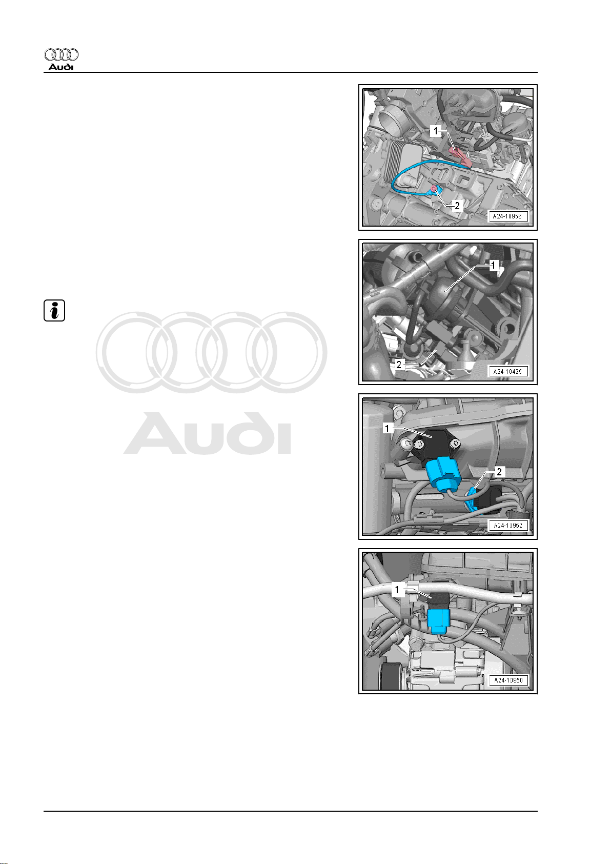
Activated charcoal filter solenoid valve 1 -N80- -1-
3. Overviews - fitting locations 23
Page 28
Protected by copyright. Copying for private or commercial purposes, in part or in whole, is not
permitted unless authorised by AUDI AG. AUDI AG does not guarantee or accept any liability
with respect to the correctness of information in this document. Copyright by AUDI AG.
Audi TT 2007 ➤
Direct petrol injection and ignition system (4-cyl. 1.8 ltr., 2.0 ltr. 4-valve turbo with timing chain) - Edition
06.2010
Fitting location of knock sensor 1 -G61-
1 - Electrical connector for knock sensor 1 -G61-
2 - Knock sensor 1 -G61-
Fitting location: below intake manifold and coolant pump
Intake manifold flap valve -N316-
1 - Vacuum unit for intake manifold flaps
2 - Intake manifold flap valve -N316-
Note
Intake manifold flaps are the same as air flow control flaps.
Intake manifold pressure sender -G71- -1- and fuel pressure
sender -G247- -2-
1 - Intake manifold pressure sender -G71-
2 - Fuel pressure sender -G247-
Intake manifold pressure sender -G71- -1-
24 Rep. Gr.24 - Mixture preparation - injection
Page 29

Protected by copyright. Copying for private or commercial purposes, in part or in whole, is not
permitted unless authorised by AUDI AG. AUDI AG does not guarantee or accept any liability
with respect to the correctness of information in this document. Copyright by AUDI AG.
Audi TT 2007 ➤
Direct petrol injection and ignition system (4-cyl. 1.8 ltr., 2.0 ltr. 4-valve turbo with timing chain) - Edition
06.2010
Intake manifold flap potentiometer -G336- -1-
Oil pressure switch
1 - Oil pressure switch for reduced oil pressure -F378-
2 - Electrical connector for oil pressure switch for reduced oil
pressure -F378-
3 - Oil pressure switch -F22-
4 - Electrical connector for oil pressure switch -F22-
Valve for oil pressure control -N428- -3-
Camshaft control valve 1 -N205- -arrow-
3. Overviews - fitting locations 25
Page 30

Protected by copyright. Copying for private or commercial purposes, in part or in whole, is not
permitted unless authorised by AUDI AG. AUDI AG does not guarantee or accept any liability
with respect to the correctness of information in this document. Copyright by AUDI AG.
Audi TT 2007 ➤
Direct petrol injection and ignition system (4-cyl. 1.8 ltr., 2.0 ltr. 4-valve turbo with timing chain) - Edition
06.2010
Ignition coils
1 - Ignition coil 1 with output stage -N70-
2 - Ignition coil 2 with output stage -N127-
3 - Ignition coil 3 with output stage -N291-
4 - Ignition coil 4 with output stage -N292-
5 - Actuator 2 for camshaft adjustment -F367- (for cylinder No. 1)
6 - Actuator 1 for camshaft adjustment -F366- (for cylinder No. 1)
7 - Actuator 3 for camshaft adjustment -F368- (for cylinder No. 2)
8 - Actuator 4 for camshaft adjustment -F369- (for cylinder No. 2)
9 - Actuator 6 for camshaft adjustment -F371- (for cylinder No. 3)
10 - Actuator 5 for camshaft adjustment -F370- (for cylinder No.
3)
11 - Actuator 7 for camshaft adjustment -F372- (for cylinder No.
4)
12 - Actuator 8 for camshaft adjustment -F373- (for cylinder No.
4)
Engine speed sender -G28- -1-
Hall sender -G40- -1-
26 Rep. Gr.24 - Mixture preparation - injection
Page 31

Protected by copyright. Copying for private or commercial purposes, in part or in whole, is not
permitted unless authorised by AUDI AG. AUDI AG does not guarantee or accept any liability
with respect to the correctness of information in this document. Copyright by AUDI AG.
Audi TT 2007 ➤
Direct petrol injection and ignition system (4-cyl. 1.8 ltr., 2.0 ltr. 4-valve turbo with timing chain) - Edition
06.2010
Electrical connectors
1 - From Hall sender -G40- and intake manifold flap potentiometer
-G336-
2 - From knock sensor 1 -G61-
3 - 8-pin connector for injectors
Coolant temperature sender -G62- -1-
Fitting location: below intake manifold in coolant pump
Radiator outlet coolant temperature sender -G83- -1-
Charge pressure sender -G31- -2-
3. Overviews - fitting locations 27
Page 32

Protected by copyright. Copying for private or commercial purposes, in part or in whole, is not
permitted unless authorised by AUDI AG. AUDI AG does not guarantee or accept any liability
with respect to the correctness of information in this document. Copyright by AUDI AG.
Audi TT 2007 ➤
Direct petrol injection and ignition system (4-cyl. 1.8 ltr., 2.0 ltr. 4-valve turbo with timing chain) - Edition
06.2010
Radiator fan control unit -J293-
1 - Connector for radiator fan control unit -J293-
Note
♦
The radiator fan control unit -J293- is integrated into the radi‐
ator fan -V7- .
♦
The fan shown in the illustration on the left is the radiator fan
-V7- .
♦
The fan shown in the illustration on the right is the radiator fan
on right of radiator -V35- .
Electrical connector
1 - For Lambda probe -G39- and Lambda probe heater -Z19-
Fitting location of Lambda probe
1 - Lambda probe -G39- and Lambda probe heater -Z19-
Electrical connector (behind cover) for Lambda probe after cata‐
lytic converter -G130- and Lambda probe 1 heater after catalytic
converter -Z29-
28 Rep. Gr.24 - Mixture preparation - injection
Page 33

Protected by copyright. Copying for private or commercial purposes, in part or in whole, is not
permitted unless authorised by AUDI AG. AUDI AG does not guarantee or accept any liability
with respect to the correctness of information in this document. Copyright by AUDI AG.
Audi TT 2007 ➤
Direct petrol injection and ignition system (4-cyl. 1.8 ltr., 2.0 ltr. 4-valve turbo with timing chain) - Edition
06.2010
Fitting location of Lambda probe
1 - Lambda probe after catalytic converter -G130- with Lambda
probe 1 heater after catalytic converter -Z29-
Note
The arrow in the illustration points in the direction of travel.
Components on turbocharger
1 - Removing and installing turbocharger ⇒ Rep. Gr. 21
2 - Tighten charge pressure control solenoid valve -N75- to 3 Nm
3 - Tighten turbocharger air recirculation valve -N249- to 7 Nm
(note installation position, refer to next illustration)
Pay attention to installation position of turbocharger air recircula‐
tion valve -N249-
Continued coolant circulation pump -V51-
Removing and installing ⇒ Rep. Gr. 19
3. Overviews - fitting locations 29
Page 34

Protected by copyright. Copying for private or commercial purposes, in part or in whole, is not
permitted unless authorised by AUDI AG. AUDI AG does not guarantee or accept any liability
with respect to the correctness of information in this document. Copyright by AUDI AG.
Audi TT 2007 ➤
Direct petrol injection and ignition system (4-cyl. 1.8 ltr., 2.0 ltr. 4-valve turbo with timing chain) - Edition
06.2010
Exhaust flap 1 valve -N321- -1-
30 Rep. Gr.24 - Mixture preparation - injection
Page 35

Protected by copyright. Copying for private or commercial purposes, in part or in whole, is not
permitted unless authorised by AUDI AG. AUDI AG does not guarantee or accept any liability
with respect to the correctness of information in this document. Copyright by AUDI AG.
Audi TT 2007 ➤
Direct petrol injection and ignition system (4-cyl. 1.8 ltr., 2.0 ltr. 4-valve turbo with timing chain) - Edition
06.2010
4 Air cleaner
4.1 Air cleaner - exploded view
1 - Spring-type clip
2 - Air hose
❑ To turbocharger
❑ Check air intake hose
for dirt and leaves
3 - Air mass meter -G70-
❑ 1.5 Nm
❑ Removing and installing
⇒ page 65
4 - Bolts
❑ For air cleaner (top sec‐
tion)
❑ 1.5 Nm
5 - Bolts
❑ For air cleaner (top sec‐
tion)
❑ 1.5 Nm
6 - Air cleaner (top section)
❑ Clean any salt residue,
leaves and dirt out of air
cleaner (top section)
7 - Filter element
❑ Always use genuine
part for air filter element
❑ Removing and installing
⇒ page 32
❑ Observe change inter‐
vals ⇒ Maintenance ;
Booklet 810
8 - Bolt
❑ For air cleaner (bottom
section)
9 - Snow screen
❑ Not installed in all vehicles
10 - Air cleaner (bottom section)
❑ Clean any salt residue, leaves and dirt out of air cleaner (bottom section)
11 - Connection for water drain hose
❑ Clean connection
12 - Water drain hose
❑ Clean water drain hose
13 - Flutter valve
❑ Clean and re-install
14 - Intake air duct
❑ To lock carrier
4. Air cleaner 31
Page 36

Protected by copyright. Copying for private or commercial purposes, in part or in whole, is not
permitted unless authorised by AUDI AG. AUDI AG does not guarantee or accept any liability
with respect to the correctness of information in this document. Copyright by AUDI AG.
Audi TT 2007 ➤
Direct petrol injection and ignition system (4-cyl. 1.8 ltr., 2.0 ltr. 4-valve turbo with timing chain) - Edition
06.2010
❑ Clean any leaves and dirt out of intake air duct
4.2 Removing and installing engine cover panel
Removing
– Carefully pull off engine cover panel. Do not jerk the cover
panel away, and do not try to pull on one side only.
Installing
– Press engine cover panel back carefully into its retainers.
– To avoid damage, do not strike the engine cover panel with
your fist or with any kind of tool.
4.3 Removing and installing air filter ele‐
ment
Removing
– Unscrew bolts -arrows- from air cleaner (top section).
Note
Disregard items 1 to 3.
– Lift up air cleaner (top section) and take out air filter element.
Installing
Note
♦
Always use genuine part for air filter element.
♦
Hose connections and hoses for charge air system must be
free of oil and grease before assembly. Do not use any lubri‐
cants containing silicone when assembling.
♦
The air cleaner housing must be clean.
♦
Secure all hose connections with the correct type of hose clips
(same as original equipment) ⇒ Parts catalogue
♦
To prevent malfunctions, cover all critical parts of the engine
air intake tract (air mass meter, intake pipes, etc.) with a clean
cloth when blowing out the air cleaner housing with com‐
pressed air.
♦
Please observe requirements for disposal.
– Check for salt residue, dirt and leaves in air mass meter and
air intake hose (engine intake side).
– Check for dirt in air intake hose from air duct.
32 Rep. Gr.24 - Mixture preparation - injection
Page 37

Protected by copyright. Copying for private or commercial purposes, in part or in whole, is not
permitted unless authorised by AUDI AG. AUDI AG does not guarantee or accept any liability
with respect to the correctness of information in this document. Copyright by AUDI AG.
Audi TT 2007 ➤
Direct petrol injection and ignition system (4-cyl. 1.8 ltr., 2.0 ltr. 4-valve turbo with timing chain) - Edition
06.2010
– Remove snow screen -1- and clean it.
Note
The snow screen is not fitted on all vehicles.
– Clean water drain -arrow- and air cleaner (bottom section).
– When installing the air filter element, check that it is properly
centred in the retainer in the air cleaner (bottom section).
– Fit the top section of the air cleaner carefully on the bottom
section, without using force. Make sure the top section of the
air cleaner is fitted straight on the air filter element (note posi‐
tion of sealing lip on air filter element).
The remaining installation steps are carried out in the reverse se‐
quence.
4.4 Removing and installing air cleaner housing
Removing
– Unscrew bolts -arrows- from air cleaner (top section).
– Lift up air cleaner (top section) and take out air filter element.
– Remove air duct leading from lock carrier to air cleaner hous‐
ing -2 and 3-.
– Slacken bolt -1-.
– Carefully lift air cleaner (bottom section).
Installing
4. Air cleaner 33
Page 38

Protected by copyright. Copying for private or commercial purposes, in part or in whole, is not
permitted unless authorised by AUDI AG. AUDI AG does not guarantee or accept any liability
with respect to the correctness of information in this document. Copyright by AUDI AG.
Audi TT 2007 ➤
Direct petrol injection and ignition system (4-cyl. 1.8 ltr., 2.0 ltr. 4-valve turbo with timing chain) - Edition
06.2010
– Remove snow screen -1- and clean it.
Note
The snow screen is not fitted on all vehicles.
– Clean water drain -arrow- and air cleaner (bottom section).
– Disconnect water drain hose -arrow- from air cleaner (bottom
section) and clean any dirt or leaves out of connection and
hose.
– When installing the air filter element, check that it is properly
centred in the retainer in the air cleaner (bottom section).
– Fit the top section of the air cleaner carefully on the bottom
section, without using force. Make sure the top section of the
air cleaner is fitted straight on the air filter element (note posi‐
tion of sealing lip on air filter element).
The remaining installation steps are carried out in the reverse se‐
quence.
34 Rep. Gr.24 - Mixture preparation - injection
Page 39

Protected by copyright. Copying for private or commercial purposes, in part or in whole, is not
permitted unless authorised by AUDI AG. AUDI AG does not guarantee or accept any liability
with respect to the correctness of information in this document. Copyright by AUDI AG.
Audi TT 2007 ➤
Direct petrol injection and ignition system (4-cyl. 1.8 ltr., 2.0 ltr. 4-valve turbo with timing chain) - Edition
06.2010
5 Intake manifold (engine codes
CDAA, CCZA and CCTA)
5.1 Intake manifold - exploded view
1 - Screw for intake air temper‐
ature sender -G42-
❑ 5 Nm
2 - Intake air temperature
sender -G42-
3 - Activated charcoal filter sol‐
enoid valve 1 -N80-
❑ With dual non-return
valve; checking
⇒ page 68
4 - Intake manifold
❑ Removing and installing
⇒ page 42
5 - Vacuum unit for air flow
control flaps (intake manifold
flaps)
6 - Bolts for high-pressure
pump
❑ 10 Nm (engine code
CDAA, 1.8 ltr.)
❑ 20 Nm (engine codes
CCZA and CCTA, 2.0
ltr.)
7 - Connecting piece for fuel
supply pipe
❑ From fuel tank
8 - Fuel pressure regulating
valve -N276-
9 - High-pressure pump
❑ With fuel pressure regu‐
lating valve -N276-
❑ An electric fuel pump
(fitted in fuel tank) supplies fuel to the mechanical high-pressure pump
❑ When installing the high-pressure fuel pump, it is essential to ensure that no dirt enters the fuel system.
❑ The fuel system must not be under pressure when installing the high-pressure pump; procedure for
reducing fuel pressure ⇒ page 4
❑ Fuel pipes must be free of tension when installed.
❑ Removing and installing ⇒ page 50
10 - Roller tappet
❑ May remain lodged in exhauster pump when high-pressure pump is removed; it can be taken out
11 - Connecting piece for fuel supply pipe to fuel rail
❑ Renew
❑ 25 Nm
12 - High-pressure fuel pipe
❑ Fuel pipes must be free of tension when installed.
5. Intake manifold (engine codes CDAA, CCZA and CCTA) 35
Page 40

Protected by copyright. Copying for private or commercial purposes, in part or in whole, is not
permitted unless authorised by AUDI AG. AUDI AG does not guarantee or accept any liability
with respect to the correctness of information in this document. Copyright by AUDI AG.
Audi TT 2007 ➤
Direct petrol injection and ignition system (4-cyl. 1.8 ltr., 2.0 ltr. 4-valve turbo with timing chain) - Edition
06.2010
❑ 20 Nm
13 - Intake manifold flap valve -N316-
14 - Injectors
❑ Renew O-ring and teflon ring
❑ Ensure correct installation position.
❑ Removing and installing ⇒ page 53
15 - Intake manifold support
16 - Bolt for intake manifold support
❑ 20 Nm
17 - Securing nut for intake manifold support
❑ 10 Nm
18 - Bolts for throttle valve module -J338-
❑ 5 Nm
19 - Throttle valve module -J338- , throttle valve drive for electric throttle -G186-
❑ Throttle valve drive angle sender 1 for electric throttle -G187- and throttle valve drive angle sender 2 for
electric throttle -G188-
❑ After throttle valve module -J338- has been renewed, it must be re-adapted to engine control unit -J623-
using a vehicle diagnostic tester
20 - Seal
❑ Renew
36 Rep. Gr.24 - Mixture preparation - injection
Page 41

Protected by copyright. Copying for private or commercial purposes, in part or in whole, is not
permitted unless authorised by AUDI AG. AUDI AG does not guarantee or accept any liability
with respect to the correctness of information in this document. Copyright by AUDI AG.
Audi TT 2007 ➤
Direct petrol injection and ignition system (4-cyl. 1.8 ltr., 2.0 ltr. 4-valve turbo with timing chain) - Edition
06.2010
5.2 Fuel rail - exploded view
1 - Injector
❑ With combustion cham‐
ber ring seal (teflon ring
seal): always renew
❑ Renew O-rings
❑ Ensure correct installa‐
tion position.
❑ Removing and installing
⇒ page 53
2 - Support ring
3 - Fuel rail
❑ Removing and installing
⇒ page 42
❑ Tighten to 8 Nm
4 - High-pressure pump
❑ With fuel pressure regu‐
lating valve -N276❑ An electric fuel pump
(fitted in fuel tank) sup‐
plies fuel to the mechan‐
ical high-pressure pump
❑ When installing the
high-pressure fuel
pump, it is essential to
ensure that no dirt en‐
ters the fuel system.
❑ The fuel system must
not be under pressure
when installing the high-
pressure pump; proce‐
dure for reducing fuel
pressure ⇒ page 4
❑ Fuel pipes must be free
of tension when instal‐
led.
❑ Removing and installing ⇒ page 50
5 - Roller tappet
6 - Fuel pressure regulating valve -N276-
7 - Bolts for high-pressure pump
❑ 10 Nm (engine code CDAA, 1.8 ltr.)
❑ 20 Nm (engine codes CCZA and CCTA, 2.0 ltr.)
8 - Connecting piece for fuel supply pipe
❑ Renew
❑ 25 Nm
9 - Union nut for fuel supply pipe
❑ 20 Nm
10 - Air flow control flaps (intake manifold flaps)
11 - Gasket
❑ Renew
12 - Intake manifold
❑ Removing and installing ⇒ page 42
5. Intake manifold (engine codes CDAA, CCZA and CCTA) 37
Page 42

Protected by copyright. Copying for private or commercial purposes, in part or in whole, is not
permitted unless authorised by AUDI AG. AUDI AG does not guarantee or accept any liability
with respect to the correctness of information in this document. Copyright by AUDI AG.
Audi TT 2007 ➤
Direct petrol injection and ignition system (4-cyl. 1.8 ltr., 2.0 ltr. 4-valve turbo with timing chain) - Edition
06.2010
13 - Vacuum unit for air flow control flaps (port separator plates)
14 - Throttle valve module -J338- , throttle valve drive for electric throttle -G186-
❑ Throttle valve drive angle sender 1 for electric throttle -G187- and throttle valve drive angle sender 2 for
electric throttle -G188-
❑ After throttle valve module -J338- has been renewed, it must be re-adapted to engine control unit -J623-
using a vehicle diagnostic tester
❑ 7 Nm
15 - Bolts for intake manifold
❑ 9 Nm
16 - Intake manifold flap potentiometer -G336-
❑ Intake manifold flap potentiometer -G336- must be re-adapted to engine control unit -J623- if it has been
renewed. Use vehicle diagnostic tester to do so.
17 - Fuel pressure sender -G247-
❑ 27 Nm
❑ Lubricate threads lightly with clean engine oil
❑ Fitting location ⇒ page 13
❑ Removing and installing ⇒ page 59
38 Rep. Gr.24 - Mixture preparation - injection
Page 43

Protected by copyright. Copying for private or commercial purposes, in part or in whole, is not
permitted unless authorised by AUDI AG. AUDI AG does not guarantee or accept any liability
with respect to the correctness of information in this document. Copyright by AUDI AG.
Audi TT 2007 ➤
Direct petrol injection and ignition system (4-cyl. 1.8 ltr., 2.0 ltr. 4-valve turbo with timing chain) - Edition
06.2010
6 Intake manifold (engine codes CESA
and CETA)
6.1 Intake manifold - exploded view
1 - Screw for intake air temper‐
ature sender -G42-
❑ 5 Nm
2 - Intake air temperature
sender -G42-
3 - Activated charcoal filter sol‐
enoid valve 1 -N80-
❑ With dual non-return
valve; checking
⇒ page 68
4 - Intake manifold
❑ Removing and installing
⇒ page 42
5 - Vacuum unit for air flow
control flaps (intake manifold
flaps)
6 - Bolts for high-pressure
pump
❑ 20 Nm
7 - Connecting piece for fuel
supply pipe
❑ From fuel tank
8 - Fuel pressure regulating
valve -N276-
9 - High-pressure pump
❑ With fuel pressure regu‐
lating valve -N276❑ An electric fuel pump
(fitted in fuel tank) sup‐
plies fuel to the mechan‐
ical high-pressure pump
❑ When installing the
high-pressure fuel pump, it is essential to ensure that no dirt enters the fuel system.
❑ The fuel system must not be under pressure when installing the high-pressure pump; procedure for
reducing fuel pressure ⇒ page 4
❑ Fuel pipes must be free of tension when installed.
❑ Removing and installing ⇒ page 50
10 - Roller tappet
❑ May remain lodged in exhauster pump when high-pressure pump is removed; it can be taken out
11 - Connecting piece for fuel supply pipe to fuel rail
❑ Renew
❑ 25 Nm
12 - High-pressure fuel pipe
❑ Fuel pipes must be free of tension when installed.
❑ 20 Nm
6. Intake manifold (engine codes CESA and CETA) 39
Page 44

Protected by copyright. Copying for private or commercial purposes, in part or in whole, is not
permitted unless authorised by AUDI AG. AUDI AG does not guarantee or accept any liability
with respect to the correctness of information in this document. Copyright by AUDI AG.
Audi TT 2007 ➤
Direct petrol injection and ignition system (4-cyl. 1.8 ltr., 2.0 ltr. 4-valve turbo with timing chain) - Edition
06.2010
13 - Intake manifold flap valve -N316-
14 - Injectors
❑ Renew O-ring and teflon ring
❑ Ensure correct installation position.
❑ Removing and installing ⇒ page 53
15 - Intake manifold support
16 - Bolt for intake manifold support
❑ 20 Nm
17 - Securing nut for intake manifold support
❑ 10 Nm
18 - Bolts for throttle valve module -J338-
❑ 5 Nm
19 - Throttle valve module -J338- , throttle valve drive for electric throttle -G186-
❑ Throttle valve drive angle sender 1 for electric throttle -G187- and throttle valve drive angle sender 2 for
electric throttle -G188-
❑ After throttle valve module -J338- has been renewed, it must be re-adapted to engine control unit -J623-
using a vehicle diagnostic tester
20 - Seal
❑ Renew
21 - Intake manifold pressure sender -G71-
22 - Bolts for intake manifold pressure sender -G71-
❑ 5 Nm
40 Rep. Gr.24 - Mixture preparation - injection
Page 45

Protected by copyright. Copying for private or commercial purposes, in part or in whole, is not
permitted unless authorised by AUDI AG. AUDI AG does not guarantee or accept any liability
with respect to the correctness of information in this document. Copyright by AUDI AG.
Audi TT 2007 ➤
Direct petrol injection and ignition system (4-cyl. 1.8 ltr., 2.0 ltr. 4-valve turbo with timing chain) - Edition
06.2010
6.2 Fuel rail - exploded view
1 - Injector
❑ With combustion cham‐
ber ring seal (teflon ring
seal): always renew
❑ Renew O-rings
❑ Ensure correct installa‐
tion position.
❑ Removing and installing
⇒ page 53
2 - Support ring
3 - Roller tappet
4 - Fuel pressure regulating
valve -N276-
5 - High-pressure pump
❑ With fuel pressure regu‐
lating valve -N276❑ An electric fuel pump
(fitted in fuel tank) sup‐
plies fuel to the mechan‐
ical high-pressure pump
❑ When installing the
high-pressure fuel
pump, it is essential to
ensure that no dirt en‐
ters the fuel system.
❑ The fuel system must
not be under pressure
when installing the high-
pressure pump; proce‐
dure for reducing fuel
pressure ⇒ page 4
❑ Fuel pipes must be free
of tension when instal‐
led.
❑ Removing and installing
⇒ page 50
6 - Bolts for high-pressure pump
❑ 20 Nm
7 - Bolts
❑ 9 Nm
8 - Connecting piece for fuel supply pipe
❑ Renew
❑ 25 Nm
9 - Union nut for fuel supply pipe
❑ 20 Nm
10 - Bolts
❑ 9 Nm
11 - Vacuum unit for air flow control flaps (intake manifold flaps)
12 - Throttle valve module -J338- , throttle valve drive for electric throttle -G186-
❑ Throttle valve drive angle sender 1 for electric throttle -G187- and throttle valve drive angle sender 2 for
electric throttle -G188-
6. Intake manifold (engine codes CESA and CETA) 41
Page 46

Protected by copyright. Copying for private or commercial purposes, in part or in whole, is not
permitted unless authorised by AUDI AG. AUDI AG does not guarantee or accept any liability
with respect to the correctness of information in this document. Copyright by AUDI AG.
Audi TT 2007 ➤
Direct petrol injection and ignition system (4-cyl. 1.8 ltr., 2.0 ltr. 4-valve turbo with timing chain) - Edition
06.2010
❑ After throttle valve module -J338- has been renewed, it must be re-adapted to engine control unit -J623-
using a vehicle diagnostic tester
❑ 7 Nm
13 - Intake air temperature sender -G42-
❑ Tighten to 5 Nm
14 - Intake manifold
❑ Removing and installing ⇒ page 42
15 - Intake manifold pressure sender -G71-
❑ Tighten to 5 Nm
16 - Intake manifold flap potentiometer -G336-
❑ Intake manifold flap potentiometer -G336- must be re-adapted to engine control unit -J623- if it has been
renewed. Use vehicle diagnostic tester to do so.
17 - Gasket
❑ Renew
18 - Air flow control flaps (intake manifold flaps)
19 - Fuel pressure sender -G247-
❑ 27 Nm
❑ Lubricate threads lightly with clean engine oil
❑ Fitting location ⇒ page 13
❑ Removing and installing ⇒ page 59
20 - Fuel rail
❑ Removing and installing ⇒ page 42
❑ Tighten to 8 Nm
6.3 Removing and installing intake manifold with fuel rail
After the fuel rail has been removed or renewed, intake manifold
flap potentiometer -G336- must be adapted to engine control unit
-J623- . Use vehicle diagnostic tester to do so.
Special tools and workshop equipment required
♦ Assembly tool -T10118-
42 Rep. Gr.24 - Mixture preparation - injection
Page 47

Protected by copyright. Copying for private or commercial purposes, in part or in whole, is not
permitted unless authorised by AUDI AG. AUDI AG does not guarantee or accept any liability
with respect to the correctness of information in this document. Copyright by AUDI AG.
Audi TT 2007 ➤
Direct petrol injection and ignition system (4-cyl. 1.8 ltr., 2.0 ltr. 4-valve turbo with timing chain) - Edition
06.2010
♦ Hose clip pliers -V.A.G 1921-
♦ Socket Torx T30 -T10347-
♦ Oil filter tool -3417-
Removing
– Remove engine cover panel.
Note
♦
The combustion chamber (teflon) ring seal and the O-ring
must always be renewed.
♦
Intake manifold - exploded view ⇒ page 35
♦
Fuel rail - exploded view ⇒ page 37
WARNING
The fuel system is pressurised. The fuel pressure in the highpressure part of the injection system must be reduced to a
residual pressure prior to opening; for procedure see
⇒ page 4 .
– Disconnect negative terminal from battery.
– Clean joint between intake manifold and cylinder head.
6. Intake manifold (engine codes CESA and CETA) 43
Page 48

Protected by copyright. Copying for private or commercial purposes, in part or in whole, is not
permitted unless authorised by AUDI AG. AUDI AG does not guarantee or accept any liability
with respect to the correctness of information in this document. Copyright by AUDI AG.
Audi TT 2007 ➤
Direct petrol injection and ignition system (4-cyl. 1.8 ltr., 2.0 ltr. 4-valve turbo with timing chain) - Edition
06.2010
– Pull cover off air duct (release clips on sides) -arrows-.
– Unclip air duct at the bottom by releasing clips -arrows-.
– Detach air duct at bottom together with air hose.
– Disconnect vacuum line -arrow- leading to activated charcoal
filter.
– Unplug following electrical connectors:
1 - Intake air temperature sender -G42-
2 - Activated charcoal filter solenoid valve 1 -N80-
3 - Throttle valve module -J338-
Unplug electrical connector -1- at Hall sender -G40- .
– Remove noise insulation ⇒ Rep. Gr. 66 .
44 Rep. Gr.24 - Mixture preparation - injection
Page 49

Protected by copyright. Copying for private or commercial purposes, in part or in whole, is not
permitted unless authorised by AUDI AG. AUDI AG does not guarantee or accept any liability
with respect to the correctness of information in this document. Copyright by AUDI AG.
Audi TT 2007 ➤
Direct petrol injection and ignition system (4-cyl. 1.8 ltr., 2.0 ltr. 4-valve turbo with timing chain) - Edition
06.2010
– Release hose clips -2- on air pipe.
– Unplug electrical connector -arrow-.
– Unscrew bolts -1 and 4- and remove air hose from throttle
valve module -J338- downwards.
– Pull out air hose.
– Disconnect vacuum line -1- at position marked -2- and remove
crankcase breather hose -3-.
– Unclip fuel supply hose from intake manifold.
Note
♦
The fuel system must not be under pressure.
♦
Use a clean cloth to catch escaping fuel.
– Release spring-type clip -1- and detach fuel supply hose from
high-pressure pump.
– Unscrew union nut for high-pressure fuel pipe -2- at high-pres‐
sure pump.
Note
Seal off open connections with clean caps. It is essential to ensure
that no dirt enters the fuel system.
– Disconnect vacuum line -arrow- at intake manifold flap valve -
N316- .
6. Intake manifold (engine codes CESA and CETA) 45
Page 50

Protected by copyright. Copying for private or commercial purposes, in part or in whole, is not
permitted unless authorised by AUDI AG. AUDI AG does not guarantee or accept any liability
with respect to the correctness of information in this document. Copyright by AUDI AG.
Audi TT 2007 ➤
Direct petrol injection and ignition system (4-cyl. 1.8 ltr., 2.0 ltr. 4-valve turbo with timing chain) - Edition
06.2010
– Remove two bolts -arrows- for coolant line from intake mani‐
fold.
Note
On vehicles with engine codes CESA and CETA, also unplug
electrical connector at intake manifold pressure sender -G71- .
– Unplug electrical connector at fuel pressure sender -G247-
-1-.
– Unplug electrical connectors -1- and -3- and detach connec‐
tors from retainer towards one side.
– Slightly loosen securing nut -1- and remove bolt -2-.
46 Rep. Gr.24 - Mixture preparation - injection
Page 51

Protected by copyright. Copying for private or commercial purposes, in part or in whole, is not
permitted unless authorised by AUDI AG. AUDI AG does not guarantee or accept any liability
with respect to the correctness of information in this document. Copyright by AUDI AG.
Audi TT 2007 ➤
Direct petrol injection and ignition system (4-cyl. 1.8 ltr., 2.0 ltr. 4-valve turbo with timing chain) - Edition
06.2010
– Loosen oil filter -arrow- with oil filter tool -3417- and remove oil
filter.
– Open cable retainer -arrow- and move wiring clear.
– Unscrew bolts from intake manifold using socket Torx T30 -
T10347- .
Note
To remove the bolts that cannot be accessed if you do not have
socket Torx T30 -T10347- , the throttle valve module -J338- must
be removed.
– Carefully pull intake manifold and fuel rail slightly away from
cylinder head.
– Unplug electrical connector -1- from intake manifold flap po‐
tentiometer -G336- and then detach intake manifold.
Note
♦
The injectors can remain in the fuel rail.
♦
Block off intake ports with a clean cloth.
– Disconnect intake manifold from fuel rail ⇒ page 47 .
Installing
– Fit intake manifold onto studs (left and right) on cylinder head.
Note
Make sure that injectors are installed correctly.
– The remaining installation steps are carried out in the reverse
sequence.
• Tightening torque: intake manifold - exploded view
⇒ page 35
• Tightening torque: fuel rail - exploded view ⇒ page 37
6.3.1 Removing and installing fuel rail
Note
Intake manifold must be removed; removing intake manifold
⇒ page 42 .
6. Intake manifold (engine codes CESA and CETA) 47
Page 52

Protected by copyright. Copying for private or commercial purposes, in part or in whole, is not
permitted unless authorised by AUDI AG. AUDI AG does not guarantee or accept any liability
with respect to the correctness of information in this document. Copyright by AUDI AG.
Audi TT 2007 ➤
Direct petrol injection and ignition system (4-cyl. 1.8 ltr., 2.0 ltr. 4-valve turbo with timing chain) - Edition
06.2010
– Release hose clip -1-.
– Remove hoses from activated charcoal filter.
– Disconnect fuel pipe at fuel rail.
– Unscrew two bolts -arrows- on fuel rail.
– Detach fuel rail from intake manifold.
Installing
– Always renew both connecting pieces for fuel supply pipe.
– Connect fuel pipe.
– The remaining installation steps are carried out in the reverse
sequence.
– Re-connect electrical connectors.
– Install intake manifold ⇒ page 42 .
48 Rep. Gr.24 - Mixture preparation - injection
Page 53

Protected by copyright. Copying for private or commercial purposes, in part or in whole, is not
permitted unless authorised by AUDI AG. AUDI AG does not guarantee or accept any liability
with respect to the correctness of information in this document. Copyright by AUDI AG.
Audi TT 2007 ➤
Direct petrol injection and ignition system (4-cyl. 1.8 ltr., 2.0 ltr. 4-valve turbo with timing chain) - Edition
06.2010
7 High-pressure pump
7.1 High-pressure pump - exploded view
WARNING
Fuel system operates under high pressure. Always dissipate
fuel pressure prior to opening fuel system. For procedure, refer
to ⇒ page 4
1 - Roller tappet
❑ May possibly remain
lodged in exhauster
pump when high-pres‐
sure pump is removed
2 - O-ring
❑ Renew
3 - High-pressure pump
❑ An electric fuel pump
(fitted in fuel tank) sup‐
plies fuel to the mechan‐
ical high-pressure pump
❑ When installing the
high-pressure fuel
pump, it is essential to
ensure that no dirt en‐
ters the fuel system.
❑ The fuel system must
not be under pressure;
procedure for reducing
fuel pressure ⇒ page 4
❑ Fuel pipes must be free
of tension when instal‐
led.
❑ Removing and installing
⇒ page 50
4 - Fuel pressure regulating
valve -N276-
5 - Aperture in exhauster pump
for high-pressure pump
6 - Injectors
❑ Renew O-ring and teflon
ring
❑ Ensure correct installa‐
tion position.
❑ Removing and installing ⇒ page 53
7 - Hall sender -G40-
8 - Camshaft control valve 1 -N205-
9 - Bolts for high-pressure pump
❑ 10 Nm (engine code CDAA, 1.8 ltr.)
❑ 20 Nm (engine codes CCZA, CCTA, CESA, CETA, 2.0 ltr.)
7. High-pressure pump 49
Page 54

Protected by copyright. Copying for private or commercial purposes, in part or in whole, is not
permitted unless authorised by AUDI AG. AUDI AG does not guarantee or accept any liability
with respect to the correctness of information in this document. Copyright by AUDI AG.
Audi TT 2007 ➤
Direct petrol injection and ignition system (4-cyl. 1.8 ltr., 2.0 ltr. 4-valve turbo with timing chain) - Edition
06.2010
10 - Connecting piece for fuel supply pipe from fuel tank
11 - Connecting piece for fuel supply pipe to fuel rail
❑ Renew
❑ Connecting piece: 25 Nm
❑ 25 Nm (engine code CDAA, 1.8 ltr.)
❑ 40 Nm (engine codes CCZA, CCTA, CESA, CETA, 2.0 ltr.)
❑ Tightening torque for union nut for fuel supply pipe: 20 Nm (engine code CDAA, 1.8 ltr.)
❑ Tightening torque for union nut for fuel supply pipe: 20 Nm (engine codes CCZA, CCTA, CESA, CETA,
2.0 ltr.)
❑ Fuel supply pipe must be free of tension when installed (make sure all parts are clean)
7.2 Removing and installing high-pressure pump
Removing
Note
♦
The high-pressure pump must only be removed when the en‐
gine is cold.
♦
When installing the high-pressure fuel pump, it is essential to
ensure that no dirt enters the fuel system.
♦
Use a cloth to catch escaping fuel.
♦
The O-ring must always be renewed.
♦
Always ensure that the high-pressure fuel pipes are free of
tension when tightening the connections.
WARNING
Fuel system operates under high pressure. Always dissipate
fuel pressure prior to opening fuel system. For procedure, refer
to ⇒ page 4
– Remove engine cover panel.
– Detach electrical connector at fuel pressure regulating valve -
N276- -1-.
Note
Illustration shows pump of 2.0 ltr. engine.
50 Rep. Gr.24 - Mixture preparation - injection
Page 55

Protected by copyright. Copying for private or commercial purposes, in part or in whole, is not
permitted unless authorised by AUDI AG. AUDI AG does not guarantee or accept any liability
with respect to the correctness of information in this document. Copyright by AUDI AG.
Audi TT 2007 ➤
Direct petrol injection and ignition system (4-cyl. 1.8 ltr., 2.0 ltr. 4-valve turbo with timing chain) - Edition
06.2010
– Disconnect both fuel lines -arrows-.
– Remove 2 bolts -arrows-.
– Carefully pull out high-pressure fuel pump. It is possible that
the roller tappet may remain lodged in the exhauster pump.
Installing
– Renew O-ring for high-pressure pump.
– Fit roller tappet in exhauster pump (check roller tappet for
damage first).
Note
♦
The roller tappet must be positioned at the lowest point when
installing the high-pressure pump.
♦
If the old high-pressure pump is re-installed, or if a used pump
is installed, the connecting piece for the fuel supply pipe (highpressure section of the system) must be renewed. Refer to
high-pressure pump - exploded view (item 11) ⇒ page 49 .
– Turn crankshaft until roller tappet is positioned at lowest point.
– Fit high-pressure pump in exhauster pump.
– Tighten bolts hand-tight.
– Renew connecting piece at high-pressure pump.
• Tightening torque: refer to exploded view of high-pressure
pump ⇒ page 49 .
– Now tighten bolts in diagonal sequence to specified torque,
refer to high-pressure pump - exploded view ⇒ page 49 .
– Tighten union nut on fuel supply pipe hand-tight. Align so that
parts are free of tension.
• Tightening torque for fuel supply pipe (union nut): intake mani‐
fold - exploded view ⇒ page 35 .
7. High-pressure pump 51
Page 56

Protected by copyright. Copying for private or commercial purposes, in part or in whole, is not
permitted unless authorised by AUDI AG. AUDI AG does not guarantee or accept any liability
with respect to the correctness of information in this document. Copyright by AUDI AG.
Audi TT 2007 ➤
Direct petrol injection and ignition system (4-cyl. 1.8 ltr., 2.0 ltr. 4-valve turbo with timing chain) - Edition
06.2010
– Re-attach electrical connector for fuel pressure regulating
valve -N276- -1-.
– Put back fuse if it has been removed.
Note
Check fuel system for leaks.
52 Rep. Gr.24 - Mixture preparation - injection
Page 57

Protected by copyright. Copying for private or commercial purposes, in part or in whole, is not
permitted unless authorised by AUDI AG. AUDI AG does not guarantee or accept any liability
with respect to the correctness of information in this document. Copyright by AUDI AG.
Audi TT 2007 ➤
Direct petrol injection and ignition system (4-cyl. 1.8 ltr., 2.0 ltr. 4-valve turbo with timing chain) - Edition
06.2010
8 Injectors
8.1 Removing and installing injectors
Special tools and workshop equipment required
♦ Tool kit with puller -T10133-
Note
Special tool T10133/2 (puller) has been modified and now has the
designation puller T10133/2 A . If you have not yet received the
new tool you can make the modification yourself.
Modifying special tool T10133/2 (puller) to make it equivalent to
puller T10133/2 A
– File out a semi-circular recess as shown in the illustration. The
recess allows the tool to be pushed further onto the injector so
the contact surface is increased.
– For identification purposes, mark the modified tool with the
letter “A” after the tool number.
Special tools and workshop equipment required
♦ Round file, approx. 6 mm
Removing
– Remove engine cover panel.
– Remove intake manifold and fuel rail ⇒ page 42 .
Removing injectors (from fuel rail)
Carefully pull injectors out of fuel rail.
8. Injectors 53
Page 58

Protected by copyright. Copying for private or commercial purposes, in part or in whole, is not
permitted unless authorised by AUDI AG. AUDI AG does not guarantee or accept any liability
with respect to the correctness of information in this document. Copyright by AUDI AG.
Audi TT 2007 ➤
Direct petrol injection and ignition system (4-cyl. 1.8 ltr., 2.0 ltr. 4-valve turbo with timing chain) - Edition
06.2010
Removing injectors (from cylinder head)
Injector (old version)
1 - Combustion chamber ring seal (teflon ring seal) - renew; when
fitting, do not grease ring or use any other lubricant
2 - Support ring is replaced by intermediate ring; see next illus‐
tration ⇒ page 54
3 - Injector
4 - Spacer ring (renew if damaged)
5 - O-ring (renew; apply thin coating of clean engine oil prior to
installation)
6 - Support ring (via this support ring, fuel rail exerts force which
secures injector in cylinder head)
Injector (new version)
1 - Renew intermediate ring
2 - Retainer
3 - Combustion chamber ring seal (teflon ring seal) - renew; when
fitting, do not grease ring or use any other lubricant
4 - Injector
5 - Spacer ring (renew if damaged)
6 - O-ring (renew; apply thin coating of clean engine oil prior to
installation)
7 - Support ring (via this support ring, fuel rail exerts force which
secures injector in cylinder head)
– Cover open inlet ports with a clean cloth.
– Unplug electrical connector at injector that is to be removed.
– Apply puller -T10133/2A- to groove on injector.
– Then attach removal tool -T10133/16- and pull out injector by
turning bolt -1-.
Note
The combustion chamber ring seal must always be renewed prior
to reinstalling the injector ⇒ page 54 .
8.1.1 Renewing combustion chamber ring seal (teflon ring seal)
Note
The combustion chamber ring seal must always be renewed prior
to reinstalling the injector.
– Carefully remove old teflon ring using suitable tools (e.g. cut
open ring using razor blade, or prise open ring with small
screwdriver and then pull off forwards). It is important to en‐
54 Rep. Gr.24 - Mixture preparation - injection
Page 59

Protected by copyright. Copying for private or commercial purposes, in part or in whole, is not
permitted unless authorised by AUDI AG. AUDI AG does not guarantee or accept any liability
with respect to the correctness of information in this document. Copyright by AUDI AG.
Audi TT 2007 ➤
Direct petrol injection and ignition system (4-cyl. 1.8 ltr., 2.0 ltr. 4-valve turbo with timing chain) - Edition
06.2010
sure that the groove and the continuous ridge in the bottom of
the groove are not damaged.
Note
The injector must be renewed if the groove is damaged.
– Before new teflon ring is fitted, any combustion residue must
be removed from ring groove and injector stem using a clean
cloth.
Note
The illustration shows an injector with “offset connector”. This can
be ignored since it is not relevant when replacing the combustion
chamber ring seal.
– Fit assembly cone -T10133/5- with new teflon ring -1- onto in‐
jector -2-.
– Use assembly sleeve -T10133/6- to press teflon ring further
onto assembly cone -T10133/5- until it seats in groove. Do not
use any lubricants during this procedure.
Note
The teflon ring is widened as it is pushed onto the injector. The
teflon ring must therefore be compressed again after it has been
fitted. This is done in two steps. The procedure is described be‐
low.
Step 1 of teflon ring seal calibration (adaption) is done with cali‐
bration sleeve -T10133/7- .
– Fit spacer sleeve -T10133/11- onto body of injector.
– Push calibration sleeve -T10133/7- over teflon ring until it
makes contact with spacer sleeve -T10133/11- by pressing
lightly and turning approx. 180°.
8. Injectors 55
Page 60

Protected by copyright. Copying for private or commercial purposes, in part or in whole, is not
permitted unless authorised by AUDI AG. AUDI AG does not guarantee or accept any liability
with respect to the correctness of information in this document. Copyright by AUDI AG.
Audi TT 2007 ➤
Direct petrol injection and ignition system (4-cyl. 1.8 ltr., 2.0 ltr. 4-valve turbo with timing chain) - Edition
06.2010
– Pull calibration sleeve -T10133/7- off again by turning it in the
opposite direction.
Use calibration sleeve -T10133/8- for step 2 of the calibration of
the teflon ring.
– Push calibration sleeve -T10133/8- over teflon ring until it
makes contact with spacer sleeve -T10133/11- by pressing
lightly and turning approx. 180°.
– Pull calibration sleeve -T10133/8- off again by turning it in the
opposite direction.
The teflon ring is now installed in the correct position.
– The teflon ring must not be lubricated.
– Fit new O-ring on injector. Lubricate O-ring lightly with clean
engine oil before installing.
– Use supplied nylon brush -T10133/4- to thoroughly clean
holes for injectors in cylinder head prior to installing injectors.
Note
♦
The teflon seal on the injector must not be oiled or greased.
♦
Make sure there is no cleaning fluid or oil in the cylinder head
bores when installing the injectors.
– Push injector by hand as far as it will go into aperture in cylin‐
der head (do not use oil or grease). Ensure that the injector is
properly seated in the cylinder head.
56 Rep. Gr.24 - Mixture preparation - injection
Page 61

Protected by copyright. Copying for private or commercial purposes, in part or in whole, is not
permitted unless authorised by AUDI AG. AUDI AG does not guarantee or accept any liability
with respect to the correctness of information in this document. Copyright by AUDI AG.
Audi TT 2007 ➤
Direct petrol injection and ignition system (4-cyl. 1.8 ltr., 2.0 ltr. 4-valve turbo with timing chain) - Edition
06.2010
Note
♦
It should be possible to insert injector easily. If necessary wait
until the combustion chamber ring seal has contracted suffi‐
ciently.
♦
Note correct installation position and ensure that injectors are
properly seated in cylinder head.
♦
If the injector cannot be pushed in by hand, use puller T10133/2A- -2- with striker -T10133/3- to insert injector.
– The remaining installation steps are carried out in the reverse
sequence.
Important: the following points must always be observed:
• Coat O-rings of high-pressure injectors with clean engine oil
to facilitate insertion into fuel rail.
• Renew all seals.
• Fuel rail must be positioned on injectors and pressed in evenly.
• Install intake manifold with fuel rail ⇒ page 42 .
8.2 Cleaning injectors
Special tools and workshop equipment required
♦ Ultrasonic cleaning unit -VAS 6418-
♦ Mounting plate for injection modules -VAS 6418/1-
♦ For cleaning fluid refer to electronic parts catalogue.
Cleaning
– Remove injectors ⇒ page 53 .
Note
Observe safety precautions and operating instructions for ultra‐
sonic unit.
– Ultrasonic unit must be filled with cleaning fluid.
Note
Ultrasonic unit must be filled with cleaning fluid up to top edge of
apertures (see detail in illustration).
– Insert injectors -1- all the way into mounting plate for injection
modules -VAS 6418/1- -2-.
8. Injectors 57
Page 62

Protected by copyright. Copying for private or commercial purposes, in part or in whole, is not
permitted unless authorised by AUDI AG. AUDI AG does not guarantee or accept any liability
with respect to the correctness of information in this document. Copyright by AUDI AG.
Audi TT 2007 ➤
Direct petrol injection and ignition system (4-cyl. 1.8 ltr., 2.0 ltr. 4-valve turbo with timing chain) - Edition
06.2010
– Immerse injectors together with mounting plate for injection
modules -VAS 6418/1- into cleaning fluid.
– Set rotary knob -4- to a temperature of 50°C.
– Select a cleaning time of 30 minutes with rotary knob -5-.
– Switch on ultrasonic unit with button -3-.
Note
The time set starts to elapse as soon as a cleaning temperature
of 50°C has been reached.
– After cleaning, renew combustion chamber ring seal (teflon
ring seal) for each injector ⇒ page 54 .
– Then re-install injectors ⇒ page 53 .
58 Rep. Gr.24 - Mixture preparation - injection
Page 63

Protected by copyright. Copying for private or commercial purposes, in part or in whole, is not
permitted unless authorised by AUDI AG. AUDI AG does not guarantee or accept any liability
with respect to the correctness of information in this document. Copyright by AUDI AG.
Audi TT 2007 ➤
Direct petrol injection and ignition system (4-cyl. 1.8 ltr., 2.0 ltr. 4-valve turbo with timing chain) - Edition
06.2010
9 Components of injection system
⇒ “9.1 Removing and installing fuel pressure sender G247 ”, page
59
⇒ “9.2 Checking fuel pressure sender G247 ”, page 60
⇒ “9.3 Checking fuel pressure and residual pressure (up to highpressure pump)”, page 62
⇒ “9.4 Removing and installing air mass meter G70 ”, page 65
⇒ “9.5 Removing and installing throttle valve module J338 ”, page
65
⇒ “9.6 Cleaning throttle valve module J338 ”, page 66
⇒ “9.7 Checking intake manifold change-over function”,
page 67
⇒ “9.8 Checking dual non-return valve of activated charcoal filter
solenoid valve 1 N80 ”, page 68
9.1 Removing and installing fuel pressure
sender -G247-
Special tools and workshop equipment required
♦ Assembly tool -T10118-
♦ Double hexagon socket 1/2", 27 mm -VAS 5301/7- or com‐
mercially available socket (27 mm)
Removing
– Pull off top engine cover panel carefully.
9. Components of injection system 59
Page 64

Protected by copyright. Copying for private or commercial purposes, in part or in whole, is not
permitted unless authorised by AUDI AG. AUDI AG does not guarantee or accept any liability
with respect to the correctness of information in this document. Copyright by AUDI AG.
Audi TT 2007 ➤
Direct petrol injection and ignition system (4-cyl. 1.8 ltr., 2.0 ltr. 4-valve turbo with timing chain) - Edition
06.2010
WARNING
The fuel system is pressurised. The fuel pressure in the highpressure part of the injection system must be reduced to a
residual pressure prior to opening; for procedure see
⇒ page 4 .
– Detach coolant pipe from intake manifold -arrows-.
– Release connector on fuel pressure sender -G247- using as‐
sembly tool -T10118- .
– Unscrew fuel pressure sender -G247- using double hexagon
socket, 1/2", 27 mm -VAS 5301/7- .
Installing:
– Install in reverse order.
– Make sure that connecting piece is tightened to specified tor‐
que before installing fuel pressure sender -G247- .
• Tightening torque for connecting piece: Fuel rail - exploded
view ⇒ page 37
• Tightening torque for fuel pressure sender -G247- : Fuel rail exploded view ⇒ page 37
9.2 Checking fuel pressure sender -G247-
Special tools and workshop equipment required
♦ Pressure sensor tester -VAS 6394-
♦ Adapter -VAS 6394/2-
♦ Test instrument adapter -VAS 5570-
♦ Torque wrench -V.A.G 1331-
♦ Vehicle diagnostic tester
Procedure
– Remove engine cover panel ⇒ page 32 .
WARNING
The fuel system is pressurised. The fuel pressure in the highpressure part of the injection system must be reduced to a
residual pressure prior to opening; for procedure see
⇒ page 4 .
– Remove fuel pressure sender -G247- ⇒ page 59 .
60 Rep. Gr.24 - Mixture preparation - injection
Page 65

Protected by copyright. Copying for private or commercial purposes, in part or in whole, is not
permitted unless authorised by AUDI AG. AUDI AG does not guarantee or accept any liability
with respect to the correctness of information in this document. Copyright by AUDI AG.
Audi TT 2007 ➤
Direct petrol injection and ignition system (4-cyl. 1.8 ltr., 2.0 ltr. 4-valve turbo with timing chain) - Edition
06.2010
– Screw in adapter -VAS 6394/2- in place of fuel pressure send‐
er -G247- and tighten adapter with the same torque as that
specified for fuel pressure sender -G247- .
• Tightening torque: fuel rail - exploded view ⇒ page 37
– Unscrew plug -2- on pressure sensor tester -VAS 6394- and
screw in the removed fuel pressure sender -G247- . Tighten
to torque normally specified for fuel pressure sender.
– Use test instrument adapter -VAS 5570- to make electrical
connection between vehicle and fuel pressure sender -G247- .
– Connect a vehicle diagnostic tester.
– Switch on ignition.
– Select “Engine electronics” in vehicle self-diagnosis.
– Then select function read “Measured values”.
– Select measured value block 140.
Display zone 3 shows the actual pressure value being transmitted
to the engine control unit by the fuel pressure sender -G247- .
– Switch on pressure sensor tester -VAS 6394- by pressing but‐
ton -A- once briefly.
Note
You can press and hold button -A- for 2 seconds to switch on the
illumination for 20 seconds.
Pressure sensor tester -VAS 6394- should indicate 0 bar. If this
is not the case, press button -C- once briefly to zero the tester.
9. Components of injection system 61
Page 66

Protected by copyright. Copying for private or commercial purposes, in part or in whole, is not
permitted unless authorised by AUDI AG. AUDI AG does not guarantee or accept any liability
with respect to the correctness of information in this document. Copyright by AUDI AG.
Audi TT 2007 ➤
Direct petrol injection and ignition system (4-cyl. 1.8 ltr., 2.0 ltr. 4-valve turbo with timing chain) - Edition
06.2010
– Connect pressure line of pressure sensor tester -VAS 6394-
to adapter -VAS 6394/2- .
– Start engine.
– Compare the pressure indicated by pressure sensor tester -
VAS 6394/1- with the actual pressure value on the vehicle
diagnostic tester .
• The pressure readings must not deviate by more than 5 bar.
– If the deviation is more than 5 bar, test a new fuel pressure
sender -G247- .
WARNING
The fuel system is pressurised. The fuel pressure in the highpressure part of the injection system must be reduced to a
residual pressure prior to opening; for procedure see
⇒ page 4 .
– Screw a new fuel pressure sender -G247- into the pressure
gauge -VAS 6394/1- .
– Repeat the test with the new fuel pressure sender -G247- and
compare the two pressure values.
If the two values still do not agree:
– Check the electrical connection between the fuel pressure
sender -G247- and the engine control unit; refer to ⇒ Current
flow diagrams, Electrical fault finding and Fitting locations.
If the values agree:
– Install the new fuel pressure sender -G247- ⇒ page 59 .
9.3 Checking fuel pressure and residual
pressure (up to high-pressure pump)
Special tools and workshop equipment required
♦ K-Jetronic pressure tester -V.A.G 1318-
♦ Fuel-resistant measuring container
♦ Protective gloves
Test conditions:
• Battery voltage at least 12.5 V.
• Fuel filter OK.
•
Fuel tank at least 1/4 full.
• Fuel pump control unit -J538- OK (check)
62 Rep. Gr.24 - Mixture preparation - injection
Page 67

Protected by copyright. Copying for private or commercial purposes, in part or in whole, is not
permitted unless authorised by AUDI AG. AUDI AG does not guarantee or accept any liability
with respect to the correctness of information in this document. Copyright by AUDI AG.
Audi TT 2007 ➤
Direct petrol injection and ignition system (4-cyl. 1.8 ltr., 2.0 ltr. 4-valve turbo with timing chain) - Edition
06.2010
• Ignition off.
Checking fuel pressure
Before removing pressure gauge, release fuel pressure by open‐
ing cut-off valve. Hold a container under the connection.
WARNING
♦ The pressure in the high-pressure part of the injection
system must be reduced to a residual pressure prior to
opening the system ⇒ page 4 .
♦ A clean cloth must then be wrapped around the connec‐
tion and the residual pressure dissipated by carefully loos‐
ening the connection.
– Push down protective sleeve -1- and disconnect fuel supply
pipe.
– First press hose connector -2- downwards -arrow A-, then
press release tabs -arrow B-.
– Pull off hose connector, keeping release tabs depressed.
– Screw connector -V.A.G 1318/23- and adapter set -V.A.G
1318/17A- onto K-Jetronic pressure tester -V.A.G 1318- .
– Fit adapter set -V.A.G 1318/17-1A- onto disconnected fuel
supply pipe.
– Screw adapter -V.A.G 1318/11- onto K-Jetronic tester -V.A.G
1318- .
9. Components of injection system 63
Page 68

Protected by copyright. Copying for private or commercial purposes, in part or in whole, is not
permitted unless authorised by AUDI AG. AUDI AG does not guarantee or accept any liability
with respect to the correctness of information in this document. Copyright by AUDI AG.
Audi TT 2007 ➤
Direct petrol injection and ignition system (4-cyl. 1.8 ltr., 2.0 ltr. 4-valve turbo with timing chain) - Edition
06.2010
– Run test hose into measuring glass -arrow-.
– Close cut-off valve on K-Jetronic pressure tester -V.A.G
1318- .
• Lever is at right angle to direction of flow -arrow-.
– Connect a vehicle diagnostic tester.
– Select “Engine electronics” in vehicle self-diagnosis.
– Then select “Final control diagnosis”.
– The fuel pump should start running.
Note
This function actuates the fuel pump.
– Read off fuel pressure on K-Jetronic pressure tester -V.A.G
1318- .
• Specification: approx. 5 bar (3 ... 6 bar).
– End this function when fuel pressure stops rising on K-Jetronic
pressure tester -V.A.G 1318- .
If specification is not obtained:
– Check delivery rate of fuel pump ⇒ Fuel supply system, petrol
engines; Rep. Gr. 20 .
Checking residual pressure
– Check system for leaks and check residual pressure by watch‐
ing the drop in pressure on the K-Jetronic pressure tester V.A.G 1318- .
• After 10 minutes pressure should still be at least 3 bar.
If the residual pressure drops below 3 bar:
♦ Check union between K-Jetronic pressure tester -V.A.G 1318-
and fuel supply pipe for leaks.
♦ Check K-Jetronic pressure tester -V.A.G 1318- for leaks.
♦ Check fuel lines and their connections for leaks.
♦ Renew fuel filter with integrated fuel pressure regulator ⇒ Fuel
supply system, petrol engines; Rep. Gr. 20 . Then repeat the
test.
♦ If fuel filter is OK, renew fuel pump ⇒ Fuel supply system,
petrol engines; Rep. Gr. 20 .
Assembly is carried out in the reverse order; note the following:
– The ignition must be switched off.
64 Rep. Gr.24 - Mixture preparation - injection
Page 69

Protected by copyright. Copying for private or commercial purposes, in part or in whole, is not
permitted unless authorised by AUDI AG. AUDI AG does not guarantee or accept any liability
with respect to the correctness of information in this document. Copyright by AUDI AG.
Audi TT 2007 ➤
Direct petrol injection and ignition system (4-cyl. 1.8 ltr., 2.0 ltr. 4-valve turbo with timing chain) - Edition
06.2010
Note
Before removing pressure gauge, release fuel pressure by open‐
ing cut-off valve. Hold a container -arrow- under the connection.
– Re-attach fuel supply pipe (make sure that all parts are clean).
Note
Check fuel system for leaks.
9.4 Removing and installing air mass meter
-G70-
Removing
– Unplug electrical connector -1- at air mass meter -G70- .
– Unscrew both bolts from air mass meter -G70- and carefully
pull air mass meter -G70- out of guide on air cleaner housing.
Installing
To ensure the proper function of the air mass meter -G70- it is
important to observe the following notes and instructions.
Note
♦
If the air filter element is very dirty or wet, dirt or water could
reach the air mass meter -G70- and affect the air mass value.
This would lead to loss of power, since a smaller injection
quantity is calculated.
♦
Always use genuine part for air filter element.
♦
Use a silicone-free lubricant when installing the air hose.
♦
Secure all hose connections with the correct type of hose clips
(same as original equipment) ⇒ Parts catalogue
– Check for salt residue, dirt and leaves in air mass meter and
air intake hose (engine intake side).
– Check for dirt in air duct leading to air filter element. If neces‐
sary, clean salt residue, dirt and leaves out of air cleaner
housing (top and bottom sections); wash out or use a vacuum
cleaner as required. Removing and installing air cleaner
⇒ page 32
The remaining installation steps are carried out in the reverse se‐
quence.
9.5 Removing and installing throttle valve module -J338-
Removing
– Remove engine cover panel ⇒ page 32 .
– Remove noise insulation ⇒ Rep. Gr. 66 .
9. Components of injection system 65
Page 70

Protected by copyright. Copying for private or commercial purposes, in part or in whole, is not
permitted unless authorised by AUDI AG. AUDI AG does not guarantee or accept any liability
with respect to the correctness of information in this document. Copyright by AUDI AG.
Audi TT 2007 ➤
Direct petrol injection and ignition system (4-cyl. 1.8 ltr., 2.0 ltr. 4-valve turbo with timing chain) - Edition
06.2010
– Unscrew bolts and clips -arrows- and remove charge air pipe
and hose from below.
– Unplug electrical connector -1- from throttle valve module -
J338- .
– Remove the four bolts -arrows- from throttle valve module -
J338- and detach throttle valve module -J338- .
Installing
– Install in reverse order.
– Clean sealing surface for seal.
– Renew seal.
• Tightening torques: intake manifold - exploded view
⇒ page 35 .
– After throttle valve module -J338- has been renewed, it must
be re-adapted to engine control unit -J623- using a vehicle di‐
agnostic tester.
9.6 Cleaning throttle valve module -J338-
Note
♦
The throttle valve module must be adapted if a new engine
control unit -J623- is installed.
♦
Take care not to scratch the throttle valve housing when clean‐
ing it.
– Remove throttle valve module -J338- ⇒ page 65 .
– Open throttle valve by hand and block it in the open position
with a suitable object (e.g. plastic or wooden wedge) -arrow-.
WARNING
Acetone is highly flammable. Please observe all accident pre‐
vention regulations and safety precautions when handling
flammable liquids. Do not use compressed air when cleaning
the throttle valve. Wear safety goggles and protective clothing
to avoid possible injury and skin contact.
66 Rep. Gr.24 - Mixture preparation - injection
Page 71

Protected by copyright. Copying for private or commercial purposes, in part or in whole, is not
permitted unless authorised by AUDI AG. AUDI AG does not guarantee or accept any liability
with respect to the correctness of information in this document. Copyright by AUDI AG.
Audi TT 2007 ➤
Direct petrol injection and ignition system (4-cyl. 1.8 ltr., 2.0 ltr. 4-valve turbo with timing chain) - Edition
06.2010
– Clean throttle valve housing, especially around the points
-arrows- where the throttle valve closes, using commercially
available acetone (DIN 53247) and a small brush.
– Wipe out throttle valve housing with a lint-free cloth.
– Allow acetone to evaporate completely and re-install throttle
valve module after cleaning.
– Erase learnt values and adapt engine control unit -J623- to
throttle valve module using a vehicle diagnostic tester.
9.7 Checking intake manifold change-over function
Only perform this test if there is a loss of engine torque (poor
flexibility or lack of pulling power).
Special tools and workshop equipment required
♦ Hand vacuum pump -VAS 6213-
Test condition:
♦ Intake manifold flap valve -N316- has been checked with a
vehicle diagnostic tester.
Perform the following steps if the intake manifold flap valve N316- is OK.
– Carefully pull off engine cover panel.
– Start engine and run at idling speed.
– Have a second mechanic rev up engine quickly (short burst of
throttle) and observe vacuum unit for intake manifold changeover.
• The vacuum unit should pick up -arrow-.
If the change-over does not operate as described:
– Check vacuum system for leaks.
– Check that change-over mechanism moves freely by operat‐
ing linkage manually.
– Check proper connection of vacuum lines.
– Check vacuum hoses for porosity.
9. Components of injection system 67
Page 72

Protected by copyright. Copying for private or commercial purposes, in part or in whole, is not
permitted unless authorised by AUDI AG. AUDI AG does not guarantee or accept any liability
with respect to the correctness of information in this document. Copyright by AUDI AG.
Audi TT 2007 ➤
Direct petrol injection and ignition system (4-cyl. 1.8 ltr., 2.0 ltr. 4-valve turbo with timing chain) - Edition
06.2010
– Disconnect vacuum hose -1- leading to vacuum unit for intake
manifold flap valve -N316- at intake manifold flap valve -N316-
-2-.
– Move adjuster ring -1- on hand vacuum pump -VAS 6213- to
position -A- to select "vacuum".
– Connect hand vacuum pump -VAS 6213- to vacuum unit for
intake manifold flap valve -N316- .
– Operate the hand vacuum pump -VAS 6213- several times.
The vacuum unit should move -arrows-.
– If vacuum unit does not move, renew vacuum unit.
9.8 Checking dual non-return valve of acti‐
vated charcoal filter solenoid valve 1 N80-
Special tools and workshop equipment required
68 Rep. Gr.24 - Mixture preparation - injection
Page 73

Protected by copyright. Copying for private or commercial purposes, in part or in whole, is not
permitted unless authorised by AUDI AG. AUDI AG does not guarantee or accept any liability
with respect to the correctness of information in this document. Copyright by AUDI AG.
Audi TT 2007 ➤
Direct petrol injection and ignition system (4-cyl. 1.8 ltr., 2.0 ltr. 4-valve turbo with timing chain) - Edition
06.2010
♦ Hand vacuum pump -VAS 6213-
♦ Auxiliary measuring set -V.A.G 1594C-
Test condition:
• Activated charcoal filter solenoid valve 1 -N80- has been
checked with a vehicle diagnostic tester and is OK.
– Carefully pull off engine cover panel.
– Unplug connector -1- and detach breather hose -3- from acti‐
vated charcoal filter solenoid valve 1 -N80- -2-.
– Move adjuster ring -1- on hand vacuum pump -VAS 6213- to
position -A- to select "vacuum".
9. Components of injection system 69
Page 74

Protected by copyright. Copying for private or commercial purposes, in part or in whole, is not
permitted unless authorised by AUDI AG. AUDI AG does not guarantee or accept any liability
with respect to the correctness of information in this document. Copyright by AUDI AG.
Audi TT 2007 ➤
Direct petrol injection and ignition system (4-cyl. 1.8 ltr., 2.0 ltr. 4-valve turbo with timing chain) - Edition
06.2010
– Connect hand vacuum pump -VAS 6213- to activated charcoal
filter solenoid valve 1 -N80- .
– Connect contacts of activated charcoal filter solenoid valve 1
-N80- -1- to battery using test leads. This will open activated
charcoal filter solenoid valve 1 -N80- .
Then immediately operate hand vacuum pump -VAS 6213- sev‐
eral times.
• Vacuum should build up.
– Again disconnect battery to cut off current supply.
If vacuum does not build up:
– Renew dual non-return valve -1-.
Dual non-return valve, activated charcoal filter solenoid valve 1 N80- and plastic hoses are combined as one unit and can only be
renewed together.
70 Rep. Gr.24 - Mixture preparation - injection
Page 75

Protected by copyright. Copying for private or commercial purposes, in part or in whole, is not
permitted unless authorised by AUDI AG. AUDI AG does not guarantee or accept any liability
with respect to the correctness of information in this document. Copyright by AUDI AG.
Audi TT 2007 ➤
Direct petrol injection and ignition system (4-cyl. 1.8 ltr., 2.0 ltr. 4-valve turbo with timing chain) - Edition
06.2010
10 Lambda probes
10.1 Lambda probes - overview
Electrical connector -1- for Lambda probe -G39- and Lambda
probe heater -Z19-
Lambda probe -G39- and Lambda probe heater -Z19- -1-
Electrical connector for Lambda probe after catalytic converter G130- and Lambda probe 1 heater after catalytic converter -Z29(behind cover)
10. Lambda probes 71
Page 76

Protected by copyright. Copying for private or commercial purposes, in part or in whole, is not
permitted unless authorised by AUDI AG. AUDI AG does not guarantee or accept any liability
with respect to the correctness of information in this document. Copyright by AUDI AG.
Audi TT 2007 ➤
Direct petrol injection and ignition system (4-cyl. 1.8 ltr., 2.0 ltr. 4-valve turbo with timing chain) - Edition
06.2010
Lambda probe after catalytic converter -G130- and Lambda probe
1 heater after catalytic converter -Z29- -1-
Note
The arrow in the illustration points in the direction of travel.
• Tightening torque: 55 Nm
Note
♦
Threads of new Lambda probes are already coated with as‐
sembly paste; the paste must not get into the slots on the probe
body.
♦
In the case of a used Lambda probe grease only the thread
with high-temperature paste. The paste must not get into the
slots on the Lambda probe body. High-temperature paste ⇒
Parts catalogue
♦
When installing, the Lambda probe wire must always be reat‐
tached at the same locations to prevent it from coming into
contact with the exhaust pipe.
Removing and installing Lambda probe -G39- and Lambda probe heater -Z19- before catalytic converter
⇒ “10.2 Removing and installing Lambda probe G39 and Lambda
probe heater Z19 before catalytic converter”, page 72 .
Removing and installing Lambda probe after catalytic converter G130- and Lambda probe 1 heater after catalytic converter -Z29-
⇒ “10.3 Removing and installing Lambda probe after catalytic
converter G130 and Lambda probe 1 heater after catalytic con‐
verter Z29 ”, page 73
10.2 Removing and installing Lambda probe
-G39- and Lambda probe heater -Z19before catalytic converter
Special tools and workshop equipment required
♦ Lambda probe open ring spanner set -3337-
72 Rep. Gr.24 - Mixture preparation - injection
Page 77

Protected by copyright. Copying for private or commercial purposes, in part or in whole, is not
permitted unless authorised by AUDI AG. AUDI AG does not guarantee or accept any liability
with respect to the correctness of information in this document. Copyright by AUDI AG.
Audi TT 2007 ➤
Direct petrol injection and ignition system (4-cyl. 1.8 ltr., 2.0 ltr. 4-valve turbo with timing chain) - Edition
06.2010
Removing
– Unplug electrical connector -1- for Lambda probe -G39- and
Lambda probe heater -Z19- .
– Unscrew Lambda probe -G39- -1- using tool from Lambda
probe open ring spanner set -3337- .
Installing
When installing, note the following:
Note
♦
Threads of new Lambda probes are already coated with as‐
sembly paste; the paste must not get into the slots on the probe
body.
♦
In the case of a used Lambda probe grease only the thread
with high-temperature paste. The paste must not get into the
slots on the Lambda probe body. High-temperature paste ⇒
Parts catalogue
♦
When installing, the Lambda probe wire must always be reat‐
tached at the same locations to prevent it from coming into
contact with the exhaust pipe.
• Tightening torque: Lambda probe - overview ⇒ page 71
10.3 Removing and installing Lambda probe
after catalytic converter -G130- and
Lambda probe 1 heater after catalytic
converter -Z29-
Special tools and workshop equipment required
♦ Lambda probe open ring spanner set -3337-
Removing
– Remove right-side cover from underbody.
10. Lambda probes 73
Page 78

Protected by copyright. Copying for private or commercial purposes, in part or in whole, is not
permitted unless authorised by AUDI AG. AUDI AG does not guarantee or accept any liability
with respect to the correctness of information in this document. Copyright by AUDI AG.
Audi TT 2007 ➤
Direct petrol injection and ignition system (4-cyl. 1.8 ltr., 2.0 ltr. 4-valve turbo with timing chain) - Edition
06.2010
– Unplug electrical connector for Lambda probe after catalytic
converter -G130- and Lambda probe 1 heater after catalytic
converter -Z29- .
– Unscrew Lambda probe after catalytic converter -G130- -1-
using tool from Lambda probe open ring spanner set -3337- .
Installing
When installing, note the following:
Note
♦
Threads of new Lambda probes are already coated with as‐
sembly paste; the paste must not get into the slots on the probe
body.
♦
In the case of a used Lambda probe grease only the thread
with high-temperature paste. The paste must not get into the
slots on the Lambda probe body. High-temperature paste ⇒
Parts catalogue
♦
When installing, the Lambda probe wire must always be reat‐
tached at the same locations to prevent it from coming into
contact with the exhaust pipe.
• Tightening torque: Lambda probe - overview ⇒ page 71
74 Rep. Gr.24 - Mixture preparation - injection
Page 79

Protected by copyright. Copying for private or commercial purposes, in part or in whole, is not
permitted unless authorised by AUDI AG. AUDI AG does not guarantee or accept any liability
with respect to the correctness of information in this document. Copyright by AUDI AG.
Audi TT 2007 ➤
Direct petrol injection and ignition system (4-cyl. 1.8 ltr., 2.0 ltr. 4-valve turbo with timing chain) - Edition
06.2010
11 Engine control unit
11.1 Wiring and component check with test
box -V.A.G 1598/42-
Special tools and workshop equipment required
♦ Adapter cable -V.A.G 1598/39-1-
♦ Adapter cable -V.A.G 1598/39-2-
♦ Test box -V.A.G 1598/42-
11. Engine control unit 75
Page 80

Protected by copyright. Copying for private or commercial purposes, in part or in whole, is not
permitted unless authorised by AUDI AG. AUDI AG does not guarantee or accept any liability
with respect to the correctness of information in this document. Copyright by AUDI AG.
Audi TT 2007 ➤
Direct petrol injection and ignition system (4-cyl. 1.8 ltr., 2.0 ltr. 4-valve turbo with timing chain) - Edition
06.2010
Note
♦
The test box has 105 sockets. The connecting cable can be
disconnected from the test box. This means that only the cable
(and not the test box) has to be purchased for future engine
control units with different types of connectors.
♦
The smaller of the two connectors on the engine control unit
has the contacts 1 to 60. The larger of the two connectors has
the contacts 1 to 94.
♦
To carry out tests on the 60-pin wiring harness connector, the
adapter cable -V.A.G 1598/39-1- is connected to connector
-A- on the test box. For components connected to 60-pin wiring
harness connector ⇒ Current flow diagrams, Electrical fault
finding and Fitting locations.
♦
To carry out tests on the 94-pin wiring harness connector, the
adapter cable -V.A.G 1598/39-2- must be connected to con‐
nectors -A- and -B- on the test box. For components connec‐
ted to 94-pin wiring harness connector ⇒ Current flow
diagrams, Electrical fault finding and Fitting locations.
♦
The test box -V.A.G 1598/42- is designed so it can be con‐
nected both to the wiring harness for the engine control unit
and to the engine control unit itself at the same time.
♦
The advantage of this is that the electronic engine control sys‐
tem remains fully functional when the test box is connected
(for example, for measuring signals when the engine is run‐
ning).
♦
The relevant test procedure will state whether it is necessary
to also connect the engine control unit to the test box.
WARNING
To prevent damage to the electronic components, select ap‐
propriate measuring range before connecting the measuring
cables and observe the test requirements.
The engine control unit has to be removed before multi-pin con‐
nectors can be unplugged from engine control unit ⇒ page 77 .
– Connect the test box -V.A.G 1598/42- to wiring harness with
adapter cable -V.A.G 1598/39-1- or adapter cable -V.A.G
1598/39-2- . Connect earth clip of test box to negative terminal
of battery. The instructions for performing the individual tests
indicate whether or not the engine control unit itself also needs
to be connected to the test box.
– Carry out test as described in appropriate repair procedures.
Installing engine control unit
Installation is performed in the reverse sequence.
– After installation, the protective housing must be re-fitted on
the control unit.
– Clean threaded holes for shear bolts to remove any residue
from locking fluid. This can be done using a thread tap.
– Always use new shear bolts.
Perform the following after reconnecting engine control unit:
– Interrogate event memory.
76 Rep. Gr.24 - Mixture preparation - injection
Page 81

Protected by copyright. Copying for private or commercial purposes, in part or in whole, is not
permitted unless authorised by AUDI AG. AUDI AG does not guarantee or accept any liability
with respect to the correctness of information in this document. Copyright by AUDI AG.
Audi TT 2007 ➤
Direct petrol injection and ignition system (4-cyl. 1.8 ltr., 2.0 ltr. 4-valve turbo with timing chain) - Edition
06.2010
11.2 Renewing engine control unit -J623-
Note
Not every engine control unit is bolted to a protective housing.
Whether a protective housing is fitted depends on the engine/
gearbox combination.
Special tools and workshop equipment required
♦ Hot air blower -VAS 1978/14A- -item 1- with nozzle attachment
-2- from wiring harness repair set -VAS 1978 B-
♦ Small, commercially available vice grip pliers -3-
Note
♦
Not every engine control unit is bolted to a protective housing.
Whether a protective housing is fitted depends on the engine/
gearbox combination.
♦
The engine control unit -1- is bolted to the protective housing
-5-. To make it more difficult to unscrew the shear bolts -4- for
locking plate -2-, their threads have been coated with locking
fluid.
♦
The protective housing has to be removed before the connec‐
tors can be unplugged from the engine control unit (e.g. to
connect the test box or renew the engine control unit).
Removing
– When renewing engine control unit, select diagnosis object
“Replace engine control unit” in “Guided Functions”.
– Switch off ignition and remove ignition key.
– Lever off caps on windscreen wiper arms with a screwdriver.
– Loosen hexagon nuts -arrows- several turns.
– Loosen wiper arms from wiper shafts by tilting them slightly.
– Completely remove hexagon nuts and detach wiper arms from
wiper shafts.
Note
If necessary, use puller -T10369- or a commercially available
puller to remove wiper arms.
11. Engine control unit 77
Page 82

Protected by copyright. Copying for private or commercial purposes, in part or in whole, is not
permitted unless authorised by AUDI AG. AUDI AG does not guarantee or accept any liability
with respect to the correctness of information in this document. Copyright by AUDI AG.
Audi TT 2007 ➤
Direct petrol injection and ignition system (4-cyl. 1.8 ltr., 2.0 ltr. 4-valve turbo with timing chain) - Edition
06.2010
– Pull off rubber seal -1- and remove plenum chamber cover
-2-.
Note
♦
Risk of damage to plenum chamber cover.
♦
Apply a small quantity of soap solution to transition between
windscreen and plenum chamber cover -2-. Then, starting at
edge of windscreen, carefully pull plenum chamber cover up‐
wards off retainer at windscreen.
– Detach plenum chamber cover -2- by pulling it carefully off re‐
tainer at windscreen.
– Move clear engine wiring harness at rear of plenum chamber
partition panel.
– Release clips -arrows- and remove engine control unit -J623- .
Perform the following work steps if a protective housing is fitted:
To help prevent unauthorised access to the connectors on the
engine control unit, the control unit is secured by means of shear
bolts to a locking plate and a metal casing.
The threads of the two shear bolts -4- which are not screwed into
the engine control unit are secured with locking fluid. To unscrew
these two bolts, the threads must therefore be heated with the hot
air blower.
78 Rep. Gr.24 - Mixture preparation - injection
Page 83

Protected by copyright. Copying for private or commercial purposes, in part or in whole, is not
permitted unless authorised by AUDI AG. AUDI AG does not guarantee or accept any liability
with respect to the correctness of information in this document. Copyright by AUDI AG.
Audi TT 2007 ➤
Direct petrol injection and ignition system (4-cyl. 1.8 ltr., 2.0 ltr. 4-valve turbo with timing chain) - Edition
06.2010
The threads of the two shear bolts -3- which are screwed into the
engine control unit are not secured with locking fluid. Do not apply
heat to the threads in the control unit housing; this is not neces‐
sary and would cause overheating of the control unit.
Select settings on hot air blower as shown in illustration, i.e. set
temperature potentiometer -2- to maximum heat output and twostage air flow switch -3- to position 3.
WARNING
Heating the thread of the locking plate also heats up the shear
bolts and parts of the metal housing. Take care to avoid burns.
It is also important to ensure that only the thread is heated and
none of the surrounding components if at all possible. These
should be covered if necessary.
Apply heat to the threads of the shear bolts on the connector side
as shown in the illustration.
Switch on the hot air blower and heat the bolt for approximately
20 ... 30 seconds.
– Unscrew shear bolts using suitable vice-grip pliers (see arrow
in illustration).
– The two shear bolts screwed into the engine control unit do
not need to be heated. They can be removed without heating.
– Detach metal locking plate from connectors.
– Unscrew two bolts securing retainers for engine control unit -
J623- .
11. Engine control unit 79
Page 84

Protected by copyright. Copying for private or commercial purposes, in part or in whole, is not
permitted unless authorised by AUDI AG. AUDI AG does not guarantee or accept any liability
with respect to the correctness of information in this document. Copyright by AUDI AG.
Audi TT 2007 ➤
Direct petrol injection and ignition system (4-cyl. 1.8 ltr., 2.0 ltr. 4-valve turbo with timing chain) - Edition
06.2010
– Release connectors on engine control unit -J623- and unplug
connectors.
– Take out old engine control unit -J623- and connect new en‐
gine control unit -J623- .
Installing engine control unit
Installation is performed in the reverse sequence.
– After installation, the locking plate must be re-fitted on the en‐
gine control unit -J623- .
– Clean threaded holes for shear bolts to remove any residue
from locking fluid. This can be done using a thread tap.
– Always use new shear bolts.
After installing a new engine control unit, the following operation
must be performed:
– Activate engine control unit via a vehicle diagnostic tester in
“Guided Functions” mode, “Replace engine control unit”.
80 Rep. Gr.24 - Mixture preparation - injection
Page 85

Protected by copyright. Copying for private or commercial purposes, in part or in whole, is not
permitted unless authorised by AUDI AG. AUDI AG does not guarantee or accept any liability
with respect to the correctness of information in this document. Copyright by AUDI AG.
Audi TT 2007 ➤
Direct petrol injection and ignition system (4-cyl. 1.8 ltr., 2.0 ltr. 4-valve turbo with timing chain) - Edition
06.2010
28 – Ignition system
1 General notes and safety precau‐
tions
1.1 General notes on ignition system
♦ The engine control unit has a self-diagnosis capability.
♦ A voltage of at least 11.5 V is required for proper operation of
the electrical components.
♦ Certain tests may lead to a fault being detected by the control
unit and stored. The event memory should therefore be inter‐
rogated and (if necessary) erased after completing the tests
and any repair work that may be required.
♦ If the engine starts, runs for a short period and then cuts out
after completing fault finding, repairs or component tests, this
may be due to the immobiliser disabling the engine control
unit. The event memory must then be interrogated and, if nec‐
essary, the control unit must be adapted.
1. General notes and safety precautions 81
Page 86

Protected by copyright. Copying for private or commercial purposes, in part or in whole, is not
permitted unless authorised by AUDI AG. AUDI AG does not guarantee or accept any liability
with respect to the correctness of information in this document. Copyright by AUDI AG.
Audi TT 2007 ➤
Direct petrol injection and ignition system (4-cyl. 1.8 ltr., 2.0 ltr. 4-valve turbo with timing chain) - Edition
06.2010
1.2 Safety precautions
Note the following if testers and measuring instruments have to
be used during a road test:
WARNING
Accidents can be caused if the driver is distracted by test
equipment while road-testing, or if test equipment is not prop‐
erly secured.
Injuries can also be caused if the passenger's airbag is trig‐
gered in a collision.
• The use of test equipment while driving causes distraction.
• There is an increased risk of injury if test equipment is not
secured.
♦ Move the passenger's seat back as far as it will go.
♦ Use only vehicle diagnosis and service information sys‐
tem -VAS 5052 A- or diagnosis system -VAS 5053- .
♦ The test equipment -1- must rest flat on the passenger's
thighs (as shown in illustration) and must be operated by
the passenger.
Caution
To prevent damage to the electronic components when dis‐
connecting the battery:
♦ Observe notes on procedure for disconnecting the battery.
– Disconnect battery ⇒ Rep. Gr. 27 .
To prevent injuries to persons and/or damage to the fuel injection
and ignition system, the following must be noted:
♦ Do not touch or disconnect ignition wiring when the engine is
running or being turned at starter speed.
♦ The ignition must be switched off before disconnecting or con‐
necting ignition system wiring, high-voltage wires and test
leads.
♦ If you want to crank the engine at starting speed without ac‐
tually starting it (e.g. compression test), first unplug the con‐
nectors from the ignition coils and the injectors. After
completing the work, interrogate and erase the event memory.
♦ Always switch off the ignition before cleaning the engine.
82 Rep. Gr.28 - Ignition system
Page 87

Protected by copyright. Copying for private or commercial purposes, in part or in whole, is not
permitted unless authorised by AUDI AG. AUDI AG does not guarantee or accept any liability
with respect to the correctness of information in this document. Copyright by AUDI AG.
Audi TT 2007 ➤
Direct petrol injection and ignition system (4-cyl. 1.8 ltr., 2.0 ltr. 4-valve turbo with timing chain) - Edition
06.2010
2 Servicing ignition system
2.1 Test data
Engine data 1.8 ltr. and 2.0 ltr. turbo FSI engine
Idling speed
is not adjustable; controlled by the idling speed
stabilisation
Engine speed limiter (deactivates injectors/closes
throttle valve)
Ignition timing is determined by the control unit.
Ignition timing cannot be adjusted.
Ignition system Multi-coil ignition system with 4 ignition coils (integrated
output stages) connected directly to spark plugs via
spark plug connectors; ignition coils can be pulled out of
cylinder head using puller - T40039 -
Firing order 1-3-4-2
640...800 rpm
approx. 6,500 rpm
2.2 Ignition system - exploded view
1 - Knock sensor 1 -G61-
❑ Contacts gold-plated
2 - Knock sensor 2 -G66-
❑ Contacts gold-plated
3 - Ignition coil with output
stage -(N70, N127, N291,
N292)-
❑ Removing and installing
⇒ page 84
❑ Use puller -T40039- for
removal
4 - Spark plug
❑ 30 Nm
❑ Use spark plug socket
and extension -3122 Bfor removal
❑ Removing and installing
⇒ Maintenance ; Book‐
let 810
5 - Bolt
❑ 20 Nm
❑ Tightening torque influ‐
ences the function of the
knock sensor
6 - Bolt
❑ 10 Nm
7 - Hall sender -G40-
❑ Contacts gold-plated
8 - O-ring
❑ Renew O-Ring if dam‐
2. Servicing ignition system 83
Page 88

Protected by copyright. Copying for private or commercial purposes, in part or in whole, is not
permitted unless authorised by AUDI AG. AUDI AG does not guarantee or accept any liability
with respect to the correctness of information in this document. Copyright by AUDI AG.
Audi TT 2007 ➤
Direct petrol injection and ignition system (4-cyl. 1.8 ltr., 2.0 ltr. 4-valve turbo with timing chain) - Edition
06.2010
aged
2.3 Removing and installing ignition coils with output stages
Special tools and workshop equipment required
♦ Puller -T40039-
Removing
– Remove engine cover panel.
– Unscrew two bolts on connector rail.
– Pull all ignition coils approx. 30 mm out of spark plug holes
using puller -T40039- .
The following step is only required on vehicles with engine codes
CESA and CETA.
– Release electrical connectors -5 to 12- at all camshaft adjust‐
ment actuators.
84 Rep. Gr.28 - Ignition system
Page 89

Protected by copyright. Copying for private or commercial purposes, in part or in whole, is not
permitted unless authorised by AUDI AG. AUDI AG does not guarantee or accept any liability
with respect to the correctness of information in this document. Copyright by AUDI AG.
Audi TT 2007 ➤
Direct petrol injection and ignition system (4-cyl. 1.8 ltr., 2.0 ltr. 4-valve turbo with timing chain) - Edition
06.2010
– Release connectors and unplug all connectors from the igni‐
tion coils at the same time.
Installing
– Fit all ignition coils loosely into spark plug holes.
– Align the ignition coils with the connectors and attach all con‐
nectors onto ignition coils simultaneously.
– Press ignition coils onto spark plugs by hand with uniform
pressure (do not use tool).
2.4 Removing and installing knock sensor 1
-G61-
Removing
– Unplug electrical connector -2- at knock sensor 1 -G61- .
– Remove coolant pump with thermostat ⇒ Engine, mechanics;
Rep. Gr. 19 .
Note
Knock sensor 1 -G61- is located below the intake manifold and
behind the coolant pump.
– Unscrew knock sensor 1 -G61- .
Installing
– Install in reverse order.
• Tightening torque: refer to exploded view of ignition system
⇒ page 83 .
2.5 Removing and installing engine speed
sender -G28-
Special tools and workshop equipment required
♦ Socket (4 mm) -T10370-
2. Servicing ignition system 85
Page 90

Protected by copyright. Copying for private or commercial purposes, in part or in whole, is not
permitted unless authorised by AUDI AG. AUDI AG does not guarantee or accept any liability
with respect to the correctness of information in this document. Copyright by AUDI AG.
Audi TT 2007 ➤
Direct petrol injection and ignition system (4-cyl. 1.8 ltr., 2.0 ltr. 4-valve turbo with timing chain) - Edition
06.2010
♦ Assembly tool -T10118-
Removing
– Remove engine cover panel.
– Pull cover off air duct (release clips on sides) -arrows-.
– Remove air pipe -1-.
Note
The air duct -item 2- does not have to be removed.
86 Rep. Gr.28 - Ignition system
Page 91

Protected by copyright. Copying for private or commercial purposes, in part or in whole, is not
permitted unless authorised by AUDI AG. AUDI AG does not guarantee or accept any liability
with respect to the correctness of information in this document. Copyright by AUDI AG.
Audi TT 2007 ➤
Direct petrol injection and ignition system (4-cyl. 1.8 ltr., 2.0 ltr. 4-valve turbo with timing chain) - Edition
06.2010
– Release hose clip -2- on air pipe.
– Unplug electrical connector -arrow-.
– Remove noise insulation ⇒ Rep. Gr. 66 .
– Unscrew bolts -1 and 4- and remove air hose from throttle
valve module -J338- downwards.
– Disconnect air hose -1- from charge air cooler and remove air
pipe downwards.
– Unplug electrical connector -1- at engine speed sender -G28- .
– Unscrew securing bolt for engine speed sender -G28- .
Installing
Installation is carried out in the reverse order; note the following:
• Tightening torque: refer to overview of fitting locations
⇒ page 8 .
2. Servicing ignition system 87
 Loading...