

Page 1
Protected by copyright. Copying for private or commercial purposes, in part or in whole, is not
permitted unless authorised by AUDI AG. AUDI AG does not guarantee or accept any liability
with respect to the correctness of information in this document. Copyright by AUDI AG.
Service
Workshop Manual
Audi TT 2007 ➤
Direct petrol injection and ignition system (4-cyl. 2.0 ltr.
4-valve turbo)
Engine ID
Edition 01.2008
BWA BPY
CDLBCDLACDM
A
Service Department. Technical Information
Page 2

Protected by copyright. Copying for private or commercial purposes, in part or in whole, is not
permitted unless authorised by AUDI AG. AUDI AG does not guarantee or accept any liability
with respect to the correctness of information in this document. Copyright by AUDI AG.
Service
List of Workshop Manual Repair GroupsList of Workshop Manual
Repair GroupsList of Workshop Manual Repair Groups
Re pa ir G ro up
24 - Mixture preparation - injection
28 - Ignition system
Technical information should always be available to the foremen and mechanics, because their
careful and constant adherence to the instructions is essential to ensure vehicle road-worthiness and
safety. In addition, the normal basic safety precautions for working on motor vehicles must, as a
matter of course, be observed.
All rights reserved.
No reproduction without prior agreement from publisher.
Copyright © 2010 Audi AG, Ingolstadt A005TT00720
Page 3

Protected by copyright. Copying for private or commercial purposes, in part or in whole, is not
permitted unless authorised by AUDI AG. AUDI AG does not guarantee or accept any liability
with respect to the correctness of information in this document. Copyright by AUDI AG.
Audi TT 2007 ➤
Direct petrol injection and ignition system (4-cyl. 2.0 ltr. 4-valve turbo) - Edition 01.2008
Contents
24 - Mixture preparation - injection . . . . . . . . . . . . . . . . . . . . . . . . . . . . . . . . . . . . . . . . 1
1 Safety precautions and rules for cleanliness . . . . . . . . . . . . . . . . . . . . . . . . . . . . . . . . . . . . 1
1.1 General notes on self-diagnosis . . . . . . . . . . . . . . . . . . . . . . . . . . . . . . . . . . . . . . . . . . . . . . 1
1.2 Safety precautions . . . . . . . . . . . . . . . . . . . . . . . . . . . . . . . . . . . . . . . . . . . . . . . . . . . . . . . . 2
1.3 Rules for cleanliness and instructions for working on fuel system . . . . . . . . . . . . . . . . . . . . 3
1.4 Important: Required procedure prior to opening high-pressure injection system . . . . . . . . 4
2 Injection system . . . . . . . . . . . . . . . . . . . . . . . . . . . . . . . . . . . . . . . . . . . . . . . . . . . . . . . . . . 6
2.1 Technical data . . . . . . . . . . . . . . . . . . . . . . . . . . . . . . . . . . . . . . . . . . . . . . . . . . . . . . . . . . 6
2.2 Overviews - fitting locations . . . . . . . . . . . . . . . . . . . . . . . . . . . . . . . . . . . . . . . . . . . . . . . . 6
2.3 Air cleaner / engine cover panel - exploded view (engines with code letters BWA and
BPY) . . . . . . . . . . . . . . . . . . . . . . . . . . . . . . . . . . . . . . . . . . . . . . . . . . . . . . . . . . . . . . . . . . 19
2.4 Removing and installing engine cover panel with air filter element - engines with code letters
BWA and BPY . . . . . . . . . . . . . . . . . . . . . . . . . . . . . . . . . . . . . . . . . . . . . . . . . . . . . . . . . . 20
2.5 Removing and installing air mass meter G70 - engines with code letters BWA and BPY . . 22
2.6 Air cleaner - exploded view (engines with code letters CDLA, CDLB and CDMA) . . . . . . 23
2.7 Removing and installing engine cover panel - engines with code letters CDLA, CDLB and
CDMA . . . . . . . . . . . . . . . . . . . . . . . . . . . . . . . . . . . . . . . . . . . . . . . . . . . . . . . . . . . . . . . . . . 24
2.8 Removing and installing air filter element - engines with code letters CDLA, CDLB and
CDMA . . . . . . . . . . . . . . . . . . . . . . . . . . . . . . . . . . . . . . . . . . . . . . . . . . . . . . . . . . . . . . . . . . 24
2.9 Removing and installing air cleaner housing - engines with code letters CDLA, CDLB and
CDMA . . . . . . . . . . . . . . . . . . . . . . . . . . . . . . . . . . . . . . . . . . . . . . . . . . . . . . . . . . . . . . . . . . 25
2.10 Removing and installing air mass meter G70 - engines with code letters CDLA, CDLB and
CDMA . . . . . . . . . . . . . . . . . . . . . . . . . . . . . . . . . . . . . . . . . . . . . . . . . . . . . . . . . . . . . . . . . . 26
2.11 Intake manifold - exploded view . . . . . . . . . . . . . . . . . . . . . . . . . . . . . . . . . . . . . . . . . . . . . . 28
2.12 Fuel rail - exploded view . . . . . . . . . . . . . . . . . . . . . . . . . . . . . . . . . . . . . . . . . . . . . . . . . . . . 30
2.13 Removing and installing intake manifold with fuel rail . . . . . . . . . . . . . . . . . . . . . . . . . . . . 31
2.14 Removing and installing fuel pressure sender G247 . . . . . . . . . . . . . . . . . . . . . . . . . . . . . . 36
2.15 Checking fuel pressure (low pressure) up to high-pressure pump . . . . . . . . . . . . . . . . . . . . 37
2.16 Checking fuel pressure and residual pressure (up to high-pressure pump) . . . . . . . . . . . . 38
2.17 High-pressure pump - exploded view . . . . . . . . . . . . . . . . . . . . . . . . . . . . . . . . . . . . . . . . . . 41
2.18 Removing and installing high-pressure pump . . . . . . . . . . . . . . . . . . . . . . . . . . . . . . . . . . 42
2.19 Removing and installing injectors . . . . . . . . . . . . . . . . . . . . . . . . . . . . . . . . . . . . . . . . . . . . 44
2.20 Cleaning injectors . . . . . . . . . . . . . . . . . . . . . . . . . . . . . . . . . . . . . . . . . . . . . . . . . . . . . . . . 48
2.21 Removing and installing intake manifold flap motor V157 with intake manifold flap
potentiometer G336 - engines with code letters BWA and BPY . . . . . . . . . . . . . . . . . . . . 49
2.22 Removing and installing intake manifold flap motor V157 with intake manifold flap
potentiometer G336 - engines with code letters CDLA, CDLB and CDMA . . . . . . . . . . . . 50
2.23 Removing and installing Lambda probe G39 and Lambda probe heater Z19 before catalytic
converter . . . . . . . . . . . . . . . . . . . . . . . . . . . . . . . . . . . . . . . . . . . . . . . . . . . . . . . . . . . . . . 52
2.24 Removing and installing Lambda probe after catalytic converter G130 and Lambda probe 1
heater, after catalytic converter Z29 . . . . . . . . . . . . . . . . . . . . . . . . . . . . . . . . . . . . . . . . . . 53
3 Engine control unit . . . . . . . . . . . . . . . . . . . . . . . . . . . . . . . . . . . . . . . . . . . . . . . . . . . . . . . . 55
3.1 Wiring and component check with test box V.A.G 1598/42 . . . . . . . . . . . . . . . . . . . . . . . . 55
3.2 Renewing engine control unit J623 . . . . . . . . . . . . . . . . . . . . . . . . . . . . . . . . . . . . . . . . . . 57
28 - Ignition system . . . . . . . . . . . . . . . . . . . . . . . . . . . . . . . . . . . . . . . . . . . . . . . . . . . . 61
1 General notes and safety precautions . . . . . . . . . . . . . . . . . . . . . . . . . . . . . . . . . . . . . . . . 61
1.1 General notes on ignition system . . . . . . . . . . . . . . . . . . . . . . . . . . . . . . . . . . . . . . . . . . . . 61
1.2 Safety precautions . . . . . . . . . . . . . . . . . . . . . . . . . . . . . . . . . . . . . . . . . . . . . . . . . . . . . . . . 62
2 Servicing ignition system . . . . . . . . . . . . . . . . . . . . . . . . . . . . . . . . . . . . . . . . . . . . . . . . . . 63
2.1 Test data . . . . . . . . . . . . . . . . . . . . . . . . . . . . . . . . . . . . . . . . . . . . . . . . . . . . . . . . . . . . . . 63
2.2 Ignition system - exploded view . . . . . . . . . . . . . . . . . . . . . . . . . . . . . . . . . . . . . . . . . . . . . . 63
2.3 Removing and installing ignition coils with output stages . . . . . . . . . . . . . . . . . . . . . . . . . . 64
Contents i
Page 4
Protected by copyright. Copying for private or commercial purposes, in part or in whole, is not
permitted unless authorised by AUDI AG. AUDI AG does not guarantee or accept any liability
with respect to the correctness of information in this document. Copyright by AUDI AG.
Audi TT 2007 ➤
Direct petrol injection and ignition system (4-cyl. 2.0 ltr. 4-valve turbo) - Edition 01.2008
ii Contents
Page 5
Protected by copyright. Copying for private or commercial purposes, in part or in whole, is not
permitted unless authorised by AUDI AG. AUDI AG does not guarantee or accept any liability
with respect to the correctness of information in this document. Copyright by AUDI AG.
Direct petrol injection and ignition system (4-cyl. 2.0 ltr. 4-valve turbo) - Edition 01.2008
24 – Mixture preparation - injection
1 Safety precautions and rules for
cleanliness
1.1 General notes on self-diagnosis
♦ The engine control unit has a self-diagnosis capability. Before
carrying out repairs and fault finding the fault memory must be
interrogated. The vacuum hoses and connections must also
be checked (unmetered air).
♦ Fuel hoses in engine compartment must only be secured with
spring-type clips. Clamping-type or screw-type clips must not
be used.
♦ A voltage of at least 11.5 V is required for proper operation of
the electrical components.
♦ Do not use sealants containing silicone. Particles of silicone
drawn into the engine will not be burnt in the engine and will
damage the Lambda probe.
♦ The vehicles are fitted with a crash/fuel shut-off system. This
system is designed to reduce the risk of a vehicle fire after a
crash by deactivating the fuel pump via the fuel pump relay.
♦ At the same time, this system also improves the engine's start‐
ing performance. When the driver's door is opened, the fuel
pump is activated for 2 seconds in order to build up pressure
in the fuel system ⇒ page 2 .
Audi TT 2007 ➤
1. Safety precautions and rules for cleanliness 1
Page 6
Protected by copyright. Copying for private or commercial purposes, in part or in whole, is not
permitted unless authorised by AUDI AG. AUDI AG does not guarantee or accept any liability
with respect to the correctness of information in this document. Copyright by AUDI AG.
Audi TT 2007 ➤
Direct petrol injection and ignition system (4-cyl. 2.0 ltr. 4-valve turbo) - Edition 01.2008
1.2 Safety precautions
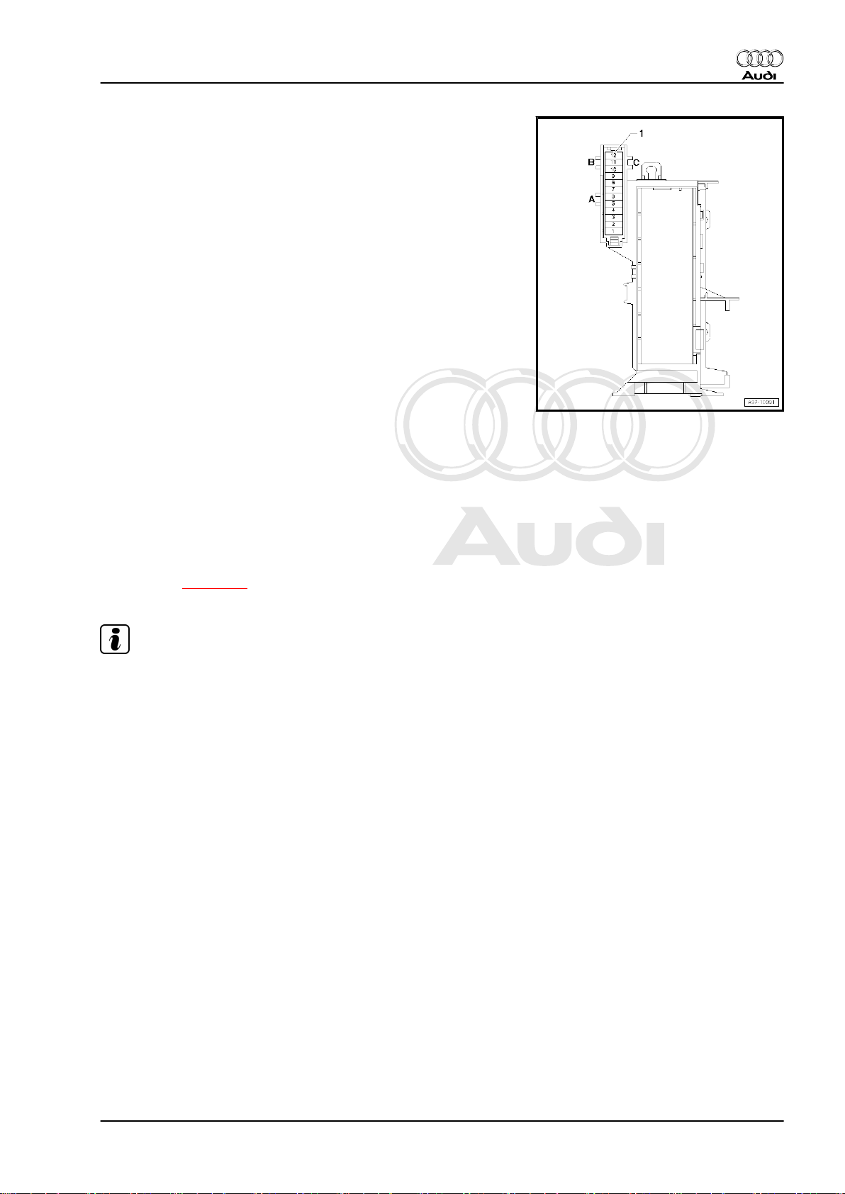
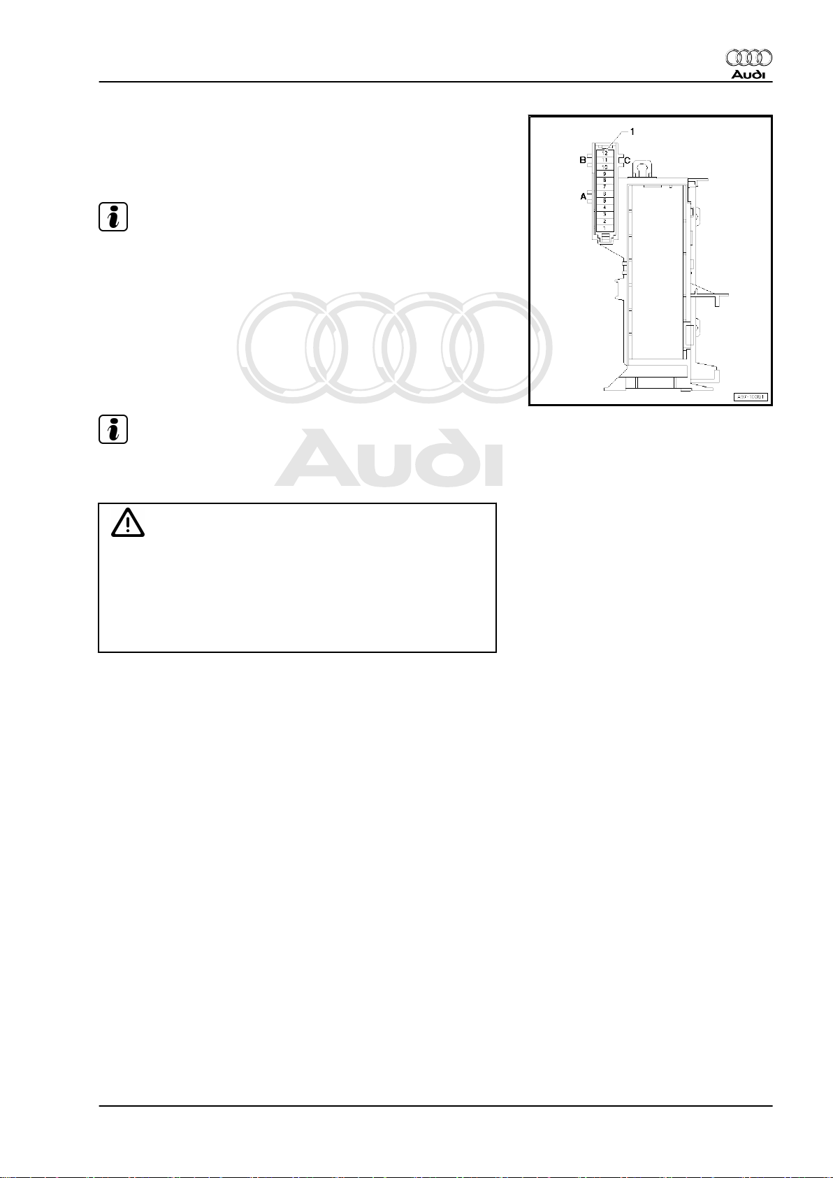
Note the following if testers and measuring instruments have to
be used during a road test:
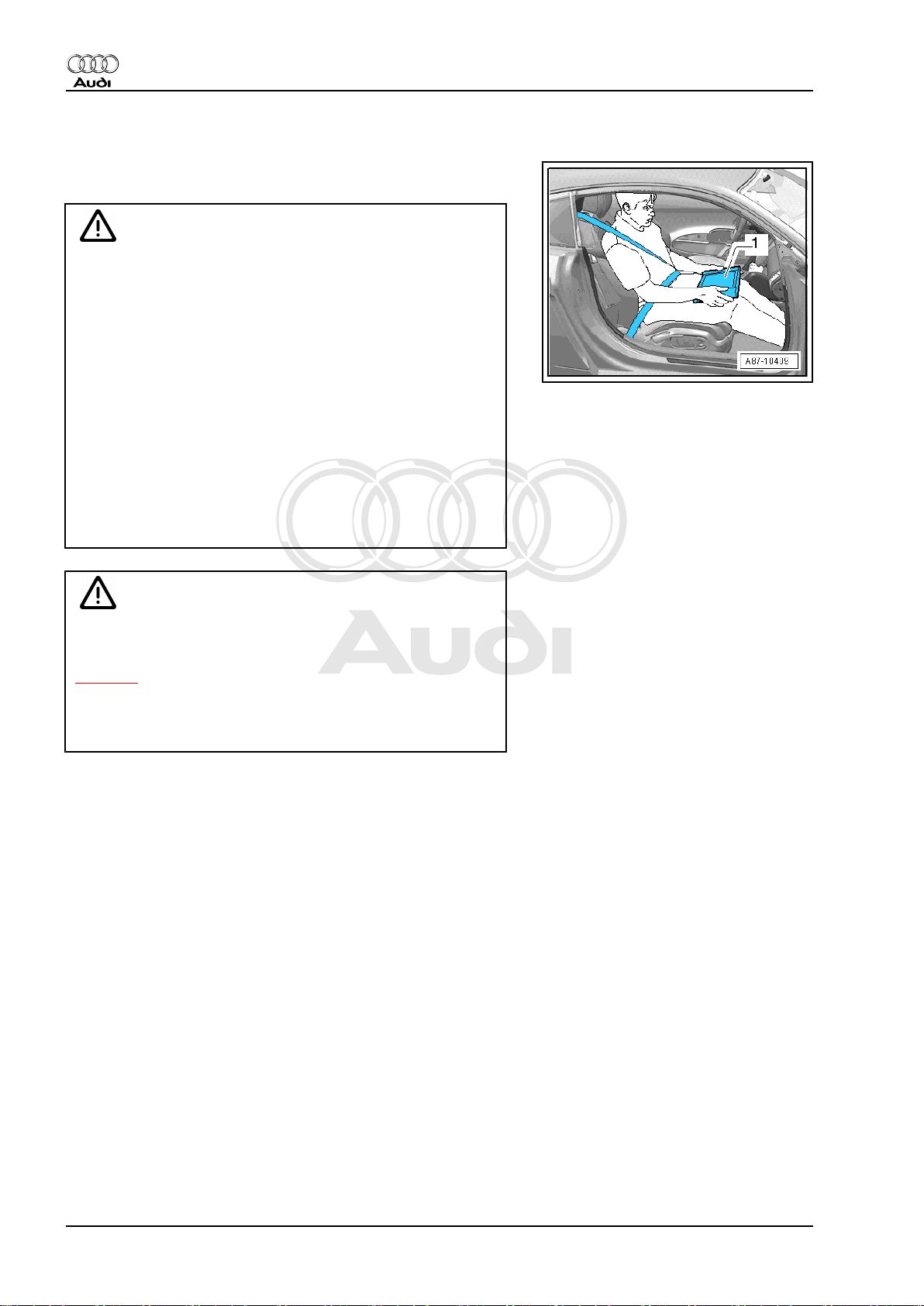
WARNING
Accidents can be caused if the driver is distracted by test
equipment while road-testing, or if test equipment is not prop‐
erly secured.
Injuries can also be caused if the passenger's airbag is trig‐
gered in a collision.
• The use of test equipment while driving causes distraction.
• There is an increased risk of injury if test equipment is not
secured.
♦ Move the passenger's seat back as far as it will go.
♦ Use only vehicle diagnosis and service information sys‐
tem -VAS 5052- or diagnosis system -VAS 5053- .
♦ The test equipment -1- must rest flat on the passenger's
thighs (as shown in illustration) and must be operated by
the passenger.
WARNING
The fuel system is pressurised. The fuel pressure in the highpressure part of the injection system must be reduced to a
residual pressure prior to opening; for procedure see
⇒ page 4 .
The connection must be opened immediately after reducing
the pressure; wrap a cloth around the connection and allow the
residual pressure (approx. 6 bar) to dissipate.
To avoid any risk of injuries to persons and/or damage to the fuel
injection and ignition system, always observe the following safety
precautions.
2 Rep. Gr.24 - Mixture preparation - injection
Page 7
Protected by copyright. Copying for private or commercial purposes, in part or in whole, is not
permitted unless authorised by AUDI AG. AUDI AG does not guarantee or accept any liability
with respect to the correctness of information in this document. Copyright by AUDI AG.
Direct petrol injection and ignition system (4-cyl. 2.0 ltr. 4-valve turbo) - Edition 01.2008
♦ For safety reasons, the battery must be disconnected before
opening the fuel system to prevent the fuel pump from being
activated by the contact switch on the driver's door.
♦ Persons wearing a cardiac pacemaker must at all times main‐
tain a safe distance from high-voltage components such as the
ignition system and gas-discharge headlights.
♦ Do not open any fuel line connections while the engine is run‐
ning.
♦ Always switch off the ignition before connecting or discon‐
necting injection or ignition system wiring or tester cables.
♦ If engine is to be operated at cranking speed without it starting
(e.g. compression test), unplug connectors from ignition coils
and remove fuse for electric fuel pump.
♦ Certain tests may lead to a fault being detected by the control
unit and stored. The fault memory should therefore be inter‐
rogated and (if necessary) erased after completing the tests
and any repair work that may be required.
♦ If the fault memory has been erased, you must generate the
readiness code again.
♦ Always switch off the ignition before cleaning the engine.
♦ Always switch off the ignition before connecting or discon‐
necting the battery, otherwise the engine control unit may be
damaged.
♦ If the engine has to be operated at the starting speed without
actually starting (e.g. to test compression pressure), detach
the four connectors from the ignition coils using assembly tool
-T40039- ⇒ page 64 . Also remove fuse for fuel pump control
unit -J538- .
Audi TT 2007 ➤
Note
♦
The fuse is located in the fuse holder in the luggage compart‐
ment (right-side).
♦
Removing fuse -SF 6- will interrupt the voltage supply “termi‐
nal 30” for the fuel pump control unit -J538- .
1.3 Rules for cleanliness and instructions for working on fuel system
Even small amounts of dirt can cause faults in the injection sys‐
tem. When working on the fuel supply/injection system, pay care‐
ful attention to the following basic rules:
♦ Carefully clean connection points and the surrounding area
with engine cleaner or brake cleaner and dry thoroughly before
opening.
♦ Plug open lines and connections with suitable protective caps
immediately.
♦ Place parts that have been removed on a clean surface and
cover them over. Use only lint-free cloths.
♦ Only install clean components; replacement parts should only
be unpacked immediately prior to installation. Do not use parts
that have been previously unpacked and stored away loose
(e.g. in toolboxes, etc.).
♦ When the system is open: Do not work with compressed air.
Do not move the vehicle unless absolutely necessary.
1. Safety precautions and rules for cleanliness 3
Page 8
Protected by copyright. Copying for private or commercial purposes, in part or in whole, is not
permitted unless authorised by AUDI AG. AUDI AG does not guarantee or accept any liability
with respect to the correctness of information in this document. Copyright by AUDI AG.
Audi TT 2007 ➤
Direct petrol injection and ignition system (4-cyl. 2.0 ltr. 4-valve turbo) - Edition 01.2008
1.4 Important: Required procedure prior to opening high-pressure injection system
Caution
The injection system consists of a high-pressure section (max‐
imum approx. 150 bar) and a low-pressure section (approx. 7
bar).
Prior to opening the high-pressure section (e.g. when removing
the high-pressure pump, fuel rail, injectors, fuel pipes or fuel
pressure sender -G247- , the fuel pressure in the high-pressure
section must be reduced to a residual pressure of approx. 7
bar. The procedure is described below.
Reducing fuel pressure in high-pressure section
– Connect up the vehicle diagnostic, testing and information
system -VAS 5051B- .
– Start engine and run at idling speed.
– Select “Engine electronics” in vehicle self-diagnosis.
– Then select function read “Measured values”.
– Select measured value block 140.
– With engine idling the fuel pressure is displayed in zone 3.
♦ Specification: between 45 and 55 bar
4 Rep. Gr.24 - Mixture preparation - injection
Page 9
Protected by copyright. Copying for private or commercial purposes, in part or in whole, is not
permitted unless authorised by AUDI AG. AUDI AG does not guarantee or accept any liability
with respect to the correctness of information in this document. Copyright by AUDI AG.
Direct petrol injection and ignition system (4-cyl. 2.0 ltr. 4-valve turbo) - Edition 01.2008
– The fuse is located in the fuse holder in the luggage compart‐
ment (right-side).
– With engine idling, pull out fuse -SF 6- for fuel pump control
unit -J538- .
Note
Removing fuse -SF 6- will interrupt the voltage supply “termi‐
nal 30” for the fuel pump control unit -J538- .
– Observe fuel pressure displayed on tester.
• The fuel pressure will decrease very quickly because the me‐
chanical high-pressure pump is no longer being supplied with
fuel by the fuel system pressurisation pump -G6- .
– Switch off ignition as soon as fuel pressure has dropped to
approx. 8 bar.
Note
Audi TT 2007 ➤
Fuel pressure must not fall below 6 bar, otherwise the engine will
stall (this could damage the catalytic converter).
WARNING
The fuel lines are still filled with fuel, however the fuel is no
longer under high pressure. Wear safety goggles and protec‐
tive clothing when opening the fuel system to avoid possible
injury and skin contact.
Before opening the high-pressure section, wrap a cloth around
the connection.
– The high-pressure system must be opened “immediately” after
reducing the fuel pressure; wrap a clean cloth around the con‐
nection. Catch the escaping fuel.
The following operations must be performed after completing re‐
pair work:
– Refit fuse.
– Erase fault memory and generate readiness code in engine
control unit in “Guided Functions” mode, using vehicle diag‐
nostic and service information system -VAS 5052 A- .
1. Safety precautions and rules for cleanliness 5
Page 10
Protected by copyright. Copying for private or commercial purposes, in part or in whole, is not
permitted unless authorised by AUDI AG. AUDI AG does not guarantee or accept any liability
with respect to the correctness of information in this document. Copyright by AUDI AG.
Audi TT 2007 ➤
Direct petrol injection and ignition system (4-cyl. 2.0 ltr. 4-valve turbo) - Edition 01.2008
2 Injection system
2.1 Technical data
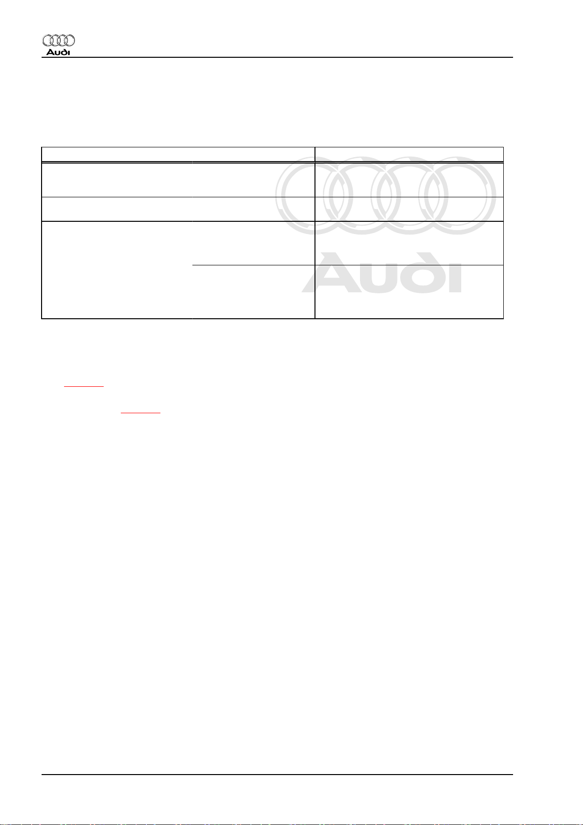
Engine data 2.0 ltr. turbo FSI engine
Idling speed is not adjustable; con‐
trolled by the idling speed stabili‐
sation
Maximum rpm governed by deac‐
tivation of fuel injectors
Fuel pressure Initial fuel pressure up to
high-pressure pump (gen‐
erated by electric fuel pump
in fuel tank)
Pressure in high-pressure
fuel circuit (generated by
mechanical single-plunger
pump) at a coolant temper‐
ature of approx. 85°C.
640 ... 800 rpm
6500 rpm
approx. 6.0 bar (identical for all operating
conditions)
approx. 50 bar at idling speed
approx. 110 bar in certain parts of operating
range.
2.2 Overviews - fitting locations
Overview of fitting locations - engines with code letters BWA and
BPY ⇒ page 6
Overview of fitting locations - engines with code letters CDLA,
CDLB and CDMA ⇒ page 9
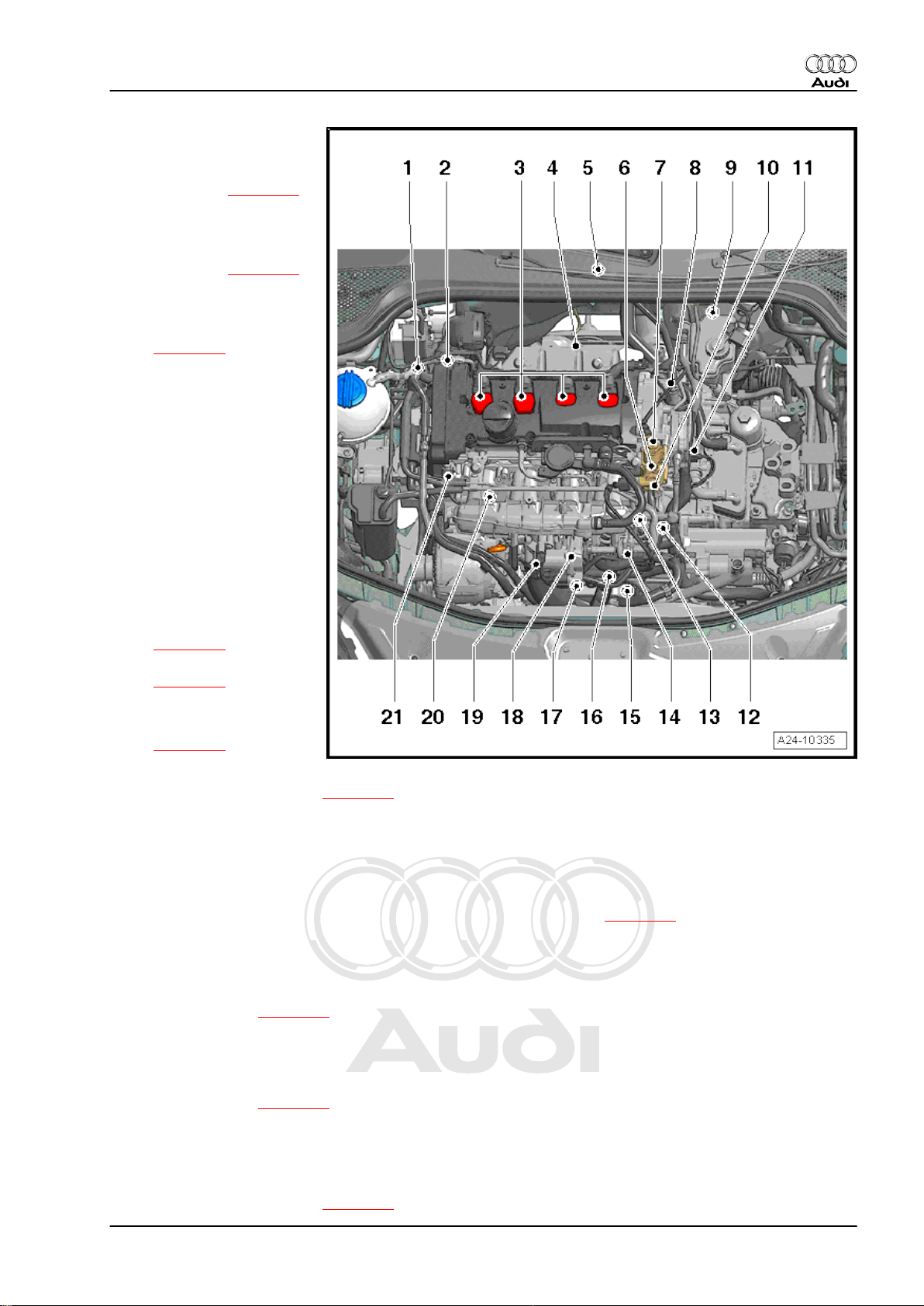
2.2.1 Overview of fitting locations - engines with code letters BWA and BPY
Components A to N are not shown in the exploded view.
6 Rep. Gr.24 - Mixture preparation - injection
Page 11
Protected by copyright. Copying for private or commercial purposes, in part or in whole, is not
permitted unless authorised by AUDI AG. AUDI AG does not guarantee or accept any liability
with respect to the correctness of information in this document. Copyright by AUDI AG.
Direct petrol injection and ignition system (4-cyl. 2.0 ltr. 4-valve turbo) - Edition 01.2008
1 - Solenoid valve for charge
pressure control -N75-
❑ Located directly on tur‐
bocharger ⇒ page 17
2 - Turbocharger air recircula‐
tion valve -N249-
❑ Located directly on tur‐
bocharger ⇒ page 17
3 - Ignition coils with output
stages
❑ Removing and installing
⇒ page 64
❑ Ignition coil 1 with output
stage -N70-
❑ Ignition coil 2 with output
stage -N127-
❑ Ignition coil 3 with output
stage -N291-
❑ Ignition coil 4 with output
stage -N292-
❑ Puller -T40039- is re‐
quired for removing igni‐
tion coils from cylinder
head.
4 - Lambda probe -G39- and
Lambda probe heater -Z19-
❑ Fitting location
⇒ page 16
❑ Removing and installing
⇒ page 52
5 - Engine control unit -J623-
❑ Removing and installing
⇒ page 57
6 - Single-plunger high-pressure pump
❑ Removing and installing ⇒ page 42
7 - Fuel pressure regulating valve -N276-
8 - Inlet camshaft control valve 1 -N205-
❑ Removing and installing ⇒ Rep. Gr. 15
9 - 6-pin connector
❑ For Lambda probe -G39- and Lambda probe heater -Z19- (black) ⇒ page 16
10 - Fuel pressure sender for low pressure -G410-
❑ 15 Nm
11 - Coolant temperature sender -G62-
❑ Fitting location ⇒ page 13
Audi TT 2007 ➤
12 - Engine speed sender -G28-
❑ Oil pressure sender -G10❑ Electrical connectors for knock sensor 1 -G61- and for knock sensor 2 -G66❑ Fitting location ⇒ page 15
13 - Intake manifold flap motor -V157- with intake manifold flap potentiometer -G336-
❑ After the fuel rail has been removed or renewed, intake manifold flap potentiometer -G336- must be
adapted to the engine control unit -J623- ; see vehicle diagnostic and service information system -VAS
5052- , “Guided Functions”
❑ Removing and installing ⇒ page 49
2. Injection system 7
Page 12
Protected by copyright. Copying for private or commercial purposes, in part or in whole, is not
permitted unless authorised by AUDI AG. AUDI AG does not guarantee or accept any liability
with respect to the correctness of information in this document. Copyright by AUDI AG.
Audi TT 2007 ➤
Direct petrol injection and ignition system (4-cyl. 2.0 ltr. 4-valve turbo) - Edition 01.2008
14 - Activated charcoal filter solenoid valve 1 -N80-
15 - Charge pressure sender -G31-
❑ Fitting location ⇒ page 15
16 - Connector
❑ For Hall sender -G40- and fuel pressure sender -G247❑ Fitting location ⇒ page 15
17 - 8-pin connector for injectors
❑ Fitting location ⇒ page 15
18 - Throttle valve module -J338- , throttle valve drive for electric throttle -G186-
❑ Throttle valve drive angle sender 1 for electric throttle -G187- and throttle valve drive angle sender 2 for
electric throttle -G188-
❑ After the throttle valve module -J338- has been renewed, it must be adapted to the engine control unit -
J623- , see vehicle diagnostic and service information system -VAS 5052- “Guided Functions”
19 - Intake air temperature sender -G42-
20 - Fuel pressure sender -G247-
❑ 22 Nm
❑ Fitting location ⇒ page 13
❑ Removing and installing ⇒ page 36
21 - Hall sender -G40- (camshaft position sensor)
❑ Electrical connector ⇒ page 13
A - Air mass meter -G70-
❑ In air cleaner (top section) ⇒ page 14
❑ Removing and installing ⇒ page 22
B - Fuel pump control unit -J538-
❑ ⇒ page 14
❑ Adaption of fuel pump must be performed after renewing fuel pump control unit -J538- . Basic setting,
measured value block 103, see ⇒ Rep. Gr. 20 or via vehicle diagnosis and service information system
-VAS 5052- “Guided Functions”
C - Brake light switch - F- and brake pedal switch -F63-
❑ Fitting location ⇒ page 15
❑ Removing and installing ⇒ Rep. Gr. 45
D - Accelerator position sender -G79- and accelerator position sender 2 -G185-
❑ Fitting location ⇒ page 12
❑ On accelerator pedal (both senders are accommodated in one housing)
❑ If accelerator pedal module or engine control unit is renewed, kick-down function must be adapted on
vehicles with automatic gearbox
❑ Removing and installing ⇒ Rep. Gr. 20
E - Clutch position sender -G476-
❑ Fitting location ⇒ page 14
❑ Removing and installing, see Power transmission, clutch ⇒ Rep. Gr. 30
F - Relay and fuse holder in electronics box
❑ Relay and fuse assignment see ⇒ Current flow diagrams, Electrical fault finding and Fitting locations
G - Radiator fan control unit -J293-
❑ Fitting location ⇒ page 16
H - Injectors
❑ In fuel rail
❑ Removing and installing ⇒ page 44
❑ Injector, cylinder 1 -N30-
8 Rep. Gr.24 - Mixture preparation - injection
Page 13

Protected by copyright. Copying for private or commercial purposes, in part or in whole, is not
permitted unless authorised by AUDI AG. AUDI AG does not guarantee or accept any liability
with respect to the correctness of information in this document. Copyright by AUDI AG.
Audi TT 2007 ➤
Direct petrol injection and ignition system (4-cyl. 2.0 ltr. 4-valve turbo) - Edition 01.2008
❑ Injector, cylinder 2 -N31❑ Injector, cylinder 3 -N32❑ Injector, cylinder 4 -N33-
The fuel injectors are high-pressure injectors. They inject fuel at high pressure (maximum approx. 110 bar)
directly into the cylinder.
I - Lambda probe after catalytic converter -G130- and Lambda probe heater 1 after catalytic converter -Z29-
❑ Fitting location ⇒ page 17
❑ Removing and installing ⇒ page 53
J - Knock sensor 1 -G61-
❑ For cylinders 1 and 2
❑ 20 Nm
❑ Fitting location ⇒ page 15
K - Knock sensor 2 -G66-
❑ For cylinders 3 and 4
❑ 20 Nm
❑ Fitting location ⇒ page 15
L - Oil pressure switch -F1-
❑ Fitting location ⇒ page 15
❑ Removing, installing and testing ⇒ Rep. Gr. 17
M - Radiator outlet coolant temperature sender -G83-
❑ Fitting location ⇒ page 13
N - Continued coolant circulation pump -V51-
❑ Fitting location ⇒ page 16
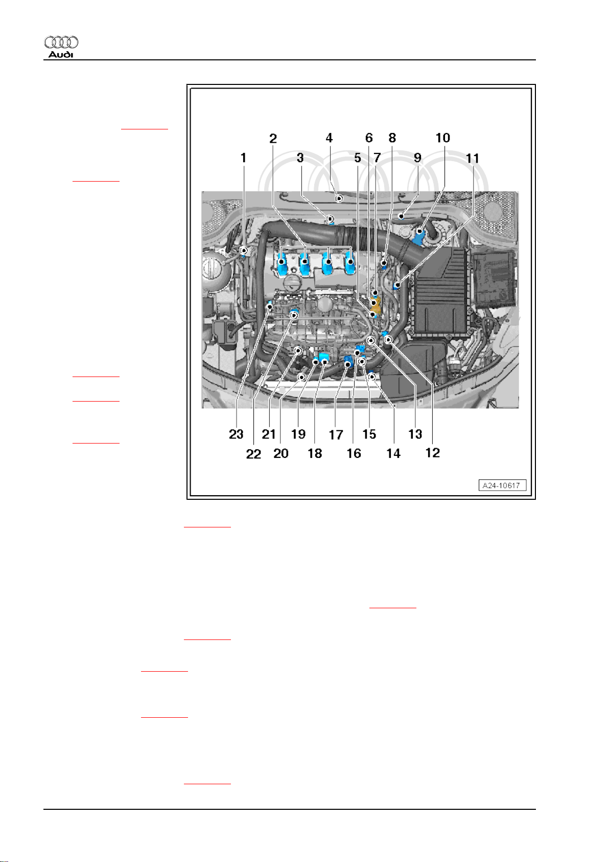
2.2.2 Overview of fitting locations - engines with code letters CDLA, CDLB and CDMA
Components A to L are not shown in the overview.
2. Injection system 9
Page 14
Protected by copyright. Copying for private or commercial purposes, in part or in whole, is not
permitted unless authorised by AUDI AG. AUDI AG does not guarantee or accept any liability
with respect to the correctness of information in this document. Copyright by AUDI AG.
Audi TT 2007 ➤
Direct petrol injection and ignition system (4-cyl. 2.0 ltr. 4-valve turbo) - Edition 01.2008
1 - Solenoid valve for charge
pressure control -N75-
❑ Located directly on tur‐
bocharger ⇒ page 17
2 - Ignition coils with output
stages
❑ Removing and installing
⇒ page 64
❑ Ignition coil 1 with output
stage -N70-
❑ Ignition coil 2 with output
stage -N127-
❑ Ignition coil 3 with output
stage -N291-
❑ Ignition coil 4 with output
stage -N292-
❑ Puller -T40039- is re‐
quired for removing igni‐
tion coils from cylinder
head.
3 - Lambda probe -G39- and
Lambda probe heater -Z19-
❑ Fitting location
⇒ page 16
❑ Removing and installing
⇒ page 52
4 - Engine control unit -J623-
❑ Removing and installing
⇒ page 57
5 - Fuel pressure sender for
low pressure -G410-
❑ 15 Nm
6 - Single-plunger high-pres‐
sure pump
❑ Removing and installing ⇒ page 42
7 - Fuel pressure regulating valve -N276-
8 - Inlet camshaft control valve 1 -N205-
❑ Removing and installing ⇒ Rep. Gr. 15
9 - 6-pin connector
❑ For Lambda probe -G39- and Lambda probe heater -Z19- (black) ⇒ page 16
10 - Air mass meter -G70-
❑ Removing and installing ⇒ page 26
11 - Coolant temperature sender -G62-
❑ Fitting location ⇒ page 13
12 - Engine speed sender -G28-
❑ Electrical connectors for knock sensor 1 -G61- and for knock sensor 2 -G66❑ Fitting location ⇒ page 15
13 - Intake manifold flap motor -V157- with intake manifold flap potentiometer -G336-
❑ After the fuel rail has been removed or renewed, intake manifold flap potentiometer -G336- must be
adapted to the engine control unit -J623- ; see vehicle diagnostic and service information system -VAS
5052- , “Guided Functions”
❑ Removing and installing ⇒ page 49
10 Rep. Gr.24 - Mixture preparation - injection
Page 15
Protected by copyright. Copying for private or commercial purposes, in part or in whole, is not
permitted unless authorised by AUDI AG. AUDI AG does not guarantee or accept any liability
with respect to the correctness of information in this document. Copyright by AUDI AG.
Audi TT 2007 ➤
Direct petrol injection and ignition system (4-cyl. 2.0 ltr. 4-valve turbo) - Edition 01.2008
14 - Charge pressure sender -G31-
❑ Fitting location ⇒ page 15
15 - Electrical connectors
❑ For injectors, Hall sender -G40- and fuel pressure sender -G247❑ Fitting location ⇒ page 15
16 - Activated charcoal filter solenoid valve 1 -N80-
❑ Fitting location ⇒ page 18
17 - Turbocharger air recirculation valve -N249-
❑ Fitting location ⇒ page 18
❑ Removing and installing ⇒ Rep. Gr. 21
18 - Throttle valve module -J338- , throttle valve drive for electric throttle operation -G186-
❑ Throttle valve drive angle sender 1 for electric throttle -G187- and throttle valve drive angle sender 2 for
electric throttle -G188-
❑ After the throttle valve module -J338- has been renewed, it must be adapted to the engine control unit -
J623- , see vehicle diagnostic and service information system -VAS 5052- “Guided Functions”
19 - Intake air temperature sender -G42-
20 - Continued coolant circulation pump -V51-
❑ Fitting location ⇒ page 16
21 - Radiator outlet coolant temperature sender -G83-
❑ Fitting location ⇒ page 13
22 - Fuel pressure sender -G247-
❑ 22 Nm
❑ Fitting location ⇒ page 13
❑ Removing and installing ⇒ page 36
23 - Hall sender -G40- (camshaft position sensor)
❑ Fitting location ⇒ page 13
A - Fuel pump control unit -J538-
❑ Fitting location ⇒ page 14
❑ Adaption of fuel pump must be performed after renewing fuel pump control unit -J538- . Basic setting for
measured value block 103, see ⇒ Rep. Gr. 20 or via vehicle diagnosis and service information system
-VAS 5052- “Guided Functions”
B - Brake light switch - F- and brake pedal switch -F63-
❑ Fitting location ⇒ page 15
❑ Removing and installing ⇒ Rep. Gr. 45
C - Accelerator position sender -G79- and accelerator position sender 2 -G185-
❑ Fitting location ⇒ page 12
❑ On accelerator pedal (both senders are accommodated in one housing)
❑ If accelerator pedal module or engine control unit is renewed, kick-down function must be adapted on
vehicles with automatic gearbox
❑ Removing and installing ⇒ Rep. Gr. 20
D - Clutch position sender -G476-
❑ Fitting location ⇒ page 14
❑ Removing and installing, see Power transmission, clutch ⇒ Rep. Gr. 30
E - Relay and fuse holder in electronics box
❑ Relay and fuse assignment see ⇒ Current flow diagrams, Electrical fault finding and Fitting locations
F - Radiator fan control unit -J293-
❑ Fitting location ⇒ page 16
2. Injection system 11
Page 16
Protected by copyright. Copying for private or commercial purposes, in part or in whole, is not
permitted unless authorised by AUDI AG. AUDI AG does not guarantee or accept any liability
with respect to the correctness of information in this document. Copyright by AUDI AG.
Audi TT 2007 ➤
Direct petrol injection and ignition system (4-cyl. 2.0 ltr. 4-valve turbo) - Edition 01.2008
G - Injectors
❑ In fuel rail
❑ Removing and installing ⇒ page 44
❑ Injector, cylinder 1 -N30❑ Injector, cylinder 2 -N31❑ Injector, cylinder 3 -N32❑ Injector, cylinder 4 -N33-
The fuel injectors are high-pressure injectors. They inject fuel at high pressure (maximum approx. 110 bar)
directly into the cylinder.
H - Lambda probe after catalytic converter -G130- and Lambda probe heater 1 after catalytic converter -Z29-
❑ Fitting location ⇒ page 17
❑ Removing and installing ⇒ page 53
I - Knock sensor 1 -G61-
❑ For cylinders 1 and 2
❑ 20 Nm
❑ Fitting location ⇒ page 15
J - Knock sensor 2 -G66-
❑ For cylinders 3 and 4
❑ 20 Nm
❑ Fitting location ⇒ page 15
K - Oil pressure switch -F1-
❑ Fitting location ⇒ page 15
❑ Removing, installing and testing ⇒ Rep. Gr. 17
L - Exhaust flap 1 valve -N321-
❑ Fitting location ⇒ page 19
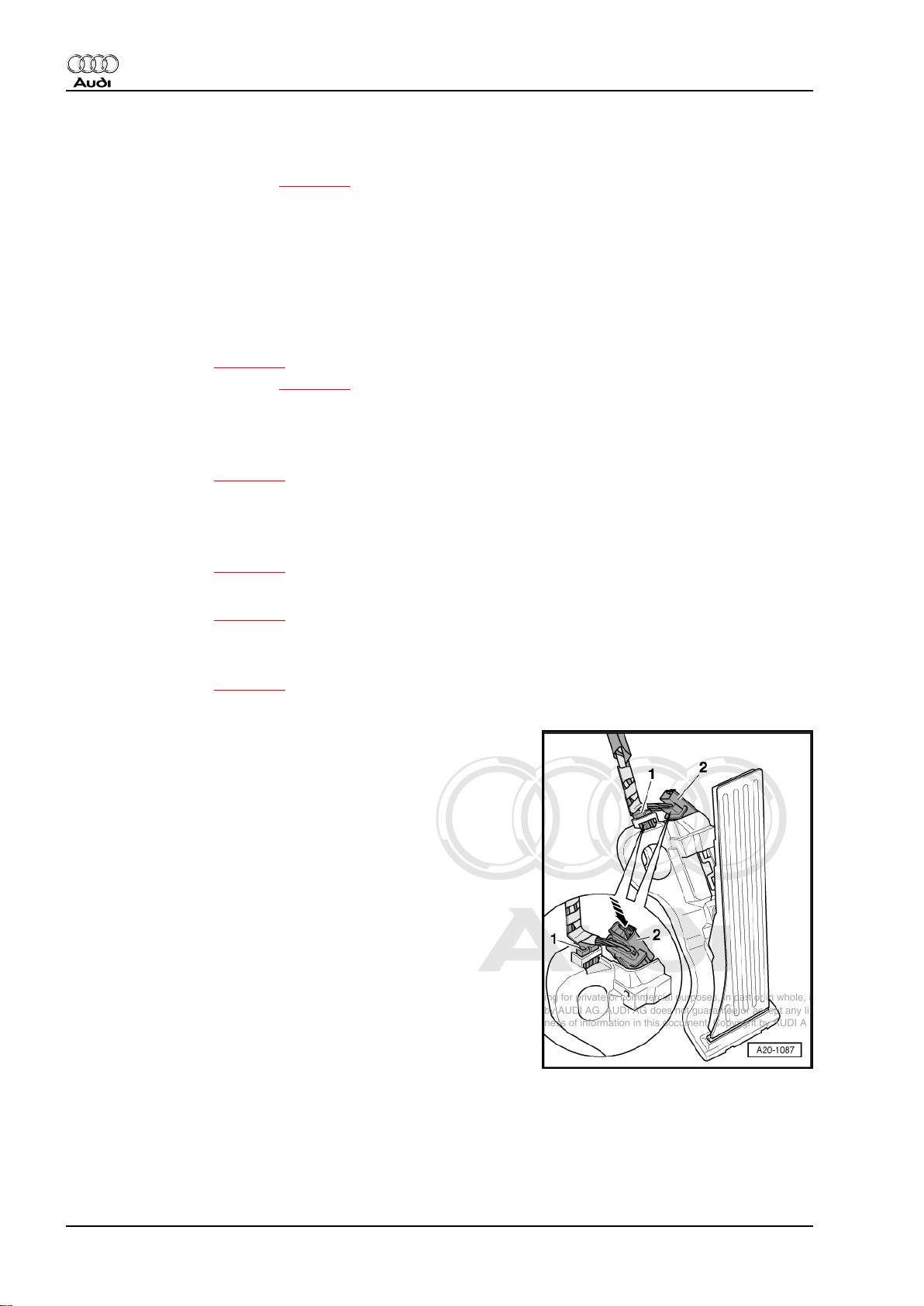
Accelerator position sender -G79- and accelerator position send‐
er 2 -G185-
2 - Electrical connector for accelerator pedal module
Removing and installing ⇒ Rep. Gr. 20
12 Rep. Gr.24 - Mixture preparation - injection
Page 17
Protected by copyright. Copying for private or commercial purposes, in part or in whole, is not
permitted unless authorised by AUDI AG. AUDI AG does not guarantee or accept any liability
with respect to the correctness of information in this document. Copyright by AUDI AG.
Direct petrol injection and ignition system (4-cyl. 2.0 ltr. 4-valve turbo) - Edition 01.2008
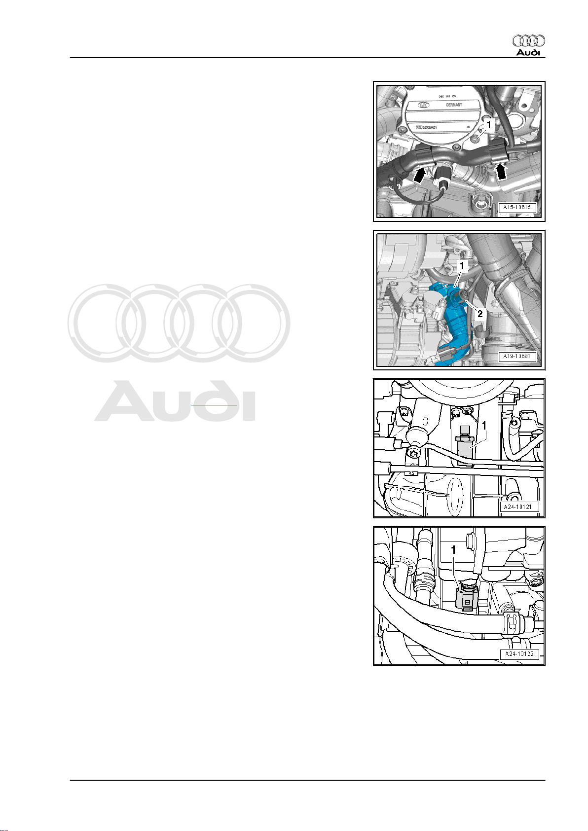
Coolant temperature sender -G62- -1-
Radiator outlet coolant temperature sender -G83- -1-
Audi TT 2007 ➤
Fuel pressure sender -G247- -1-
• Removing and installing ⇒ page 36
Hall sender -G40- -1-
2. Injection system 13
Page 18
Protected by copyright. Copying for private or commercial purposes, in part or in whole, is not
permitted unless authorised by AUDI AG. AUDI AG does not guarantee or accept any liability
with respect to the correctness of information in this document. Copyright by AUDI AG.
Audi TT 2007 ➤
Direct petrol injection and ignition system (4-cyl. 2.0 ltr. 4-valve turbo) - Edition 01.2008
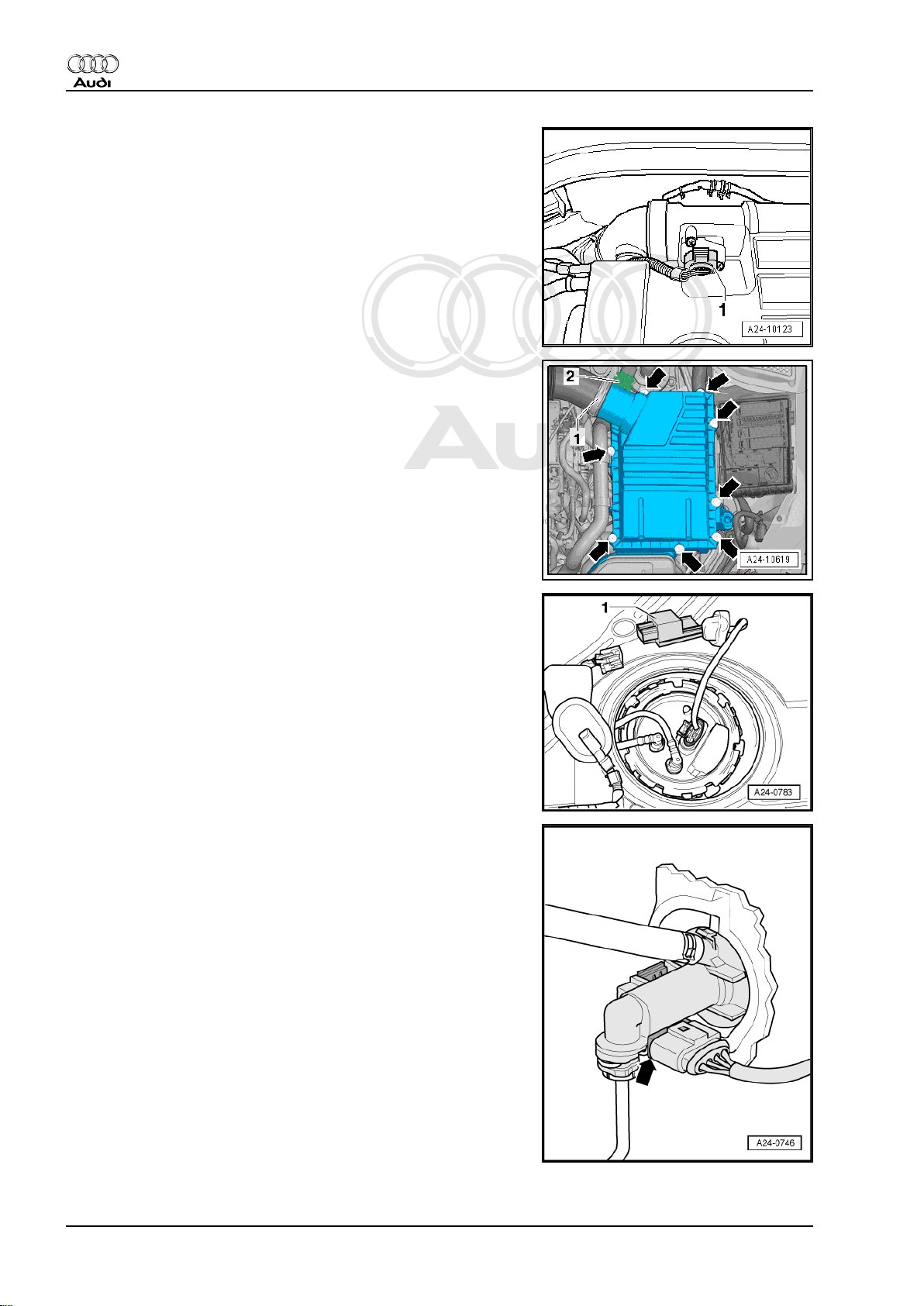
Air mass meter -G70- -1- “engines with code letters BWA and
BPY”
Air mass meter -G70- -1- “engines with code letters CDLA, CDLB
and CDMA”
Fuel pump control unit -J538- -1-
• Adaption of fuel pump must be performed after renewing fuel
pump control unit -J538- . Basic setting, measured value block
103, refer to ⇒ Rep. Gr. 20
Clutch position sender -G476-
Removing and installing, see Power transmission, clutch ⇒ Rep.
Gr. 30
14 Rep. Gr.24 - Mixture preparation - injection
Page 19
Protected by copyright. Copying for private or commercial purposes, in part or in whole, is not
permitted unless authorised by AUDI AG. AUDI AG does not guarantee or accept any liability
with respect to the correctness of information in this document. Copyright by AUDI AG.
Direct petrol injection and ignition system (4-cyl. 2.0 ltr. 4-valve turbo) - Edition 01.2008
Brake light switch -F- and brake pedal switch -F63-
Removing and installing ⇒ Rep. Gr. 45
Electrical connectors
1 - 3-pin connector (green) for knock sensor 1 -G61-
2 - 3-pin connector (brown) for knock sensor 2 -G66-
3 - Oil pressure switch -F1-
4 - Engine speed sender -G28-
5 - 3-pin electrical connector (grey) for engine speed sender G28-
Audi TT 2007 ➤
Fitting locations of components below intake manifold
1 - Knock sensor 1 -G61-
2 - Knock sensor 2 -G66-
3 - Oil pressure switch -F1-
4 - 3-pin connector (brown) for knock sensor 2 -G66-
5 - 3-pin electrical connector (grey) for engine speed sender G28-
6 - Electrical connector for Hall sender -G40- and fuel pressure
sender -G247-
7 - 8-pin connector for injectors
Charge air pressure sender -G31- -2-
2. Injection system 15
Page 20
Protected by copyright. Copying for private or commercial purposes, in part or in whole, is not
permitted unless authorised by AUDI AG. AUDI AG does not guarantee or accept any liability
with respect to the correctness of information in this document. Copyright by AUDI AG.
Audi TT 2007 ➤
Direct petrol injection and ignition system (4-cyl. 2.0 ltr. 4-valve turbo) - Edition 01.2008
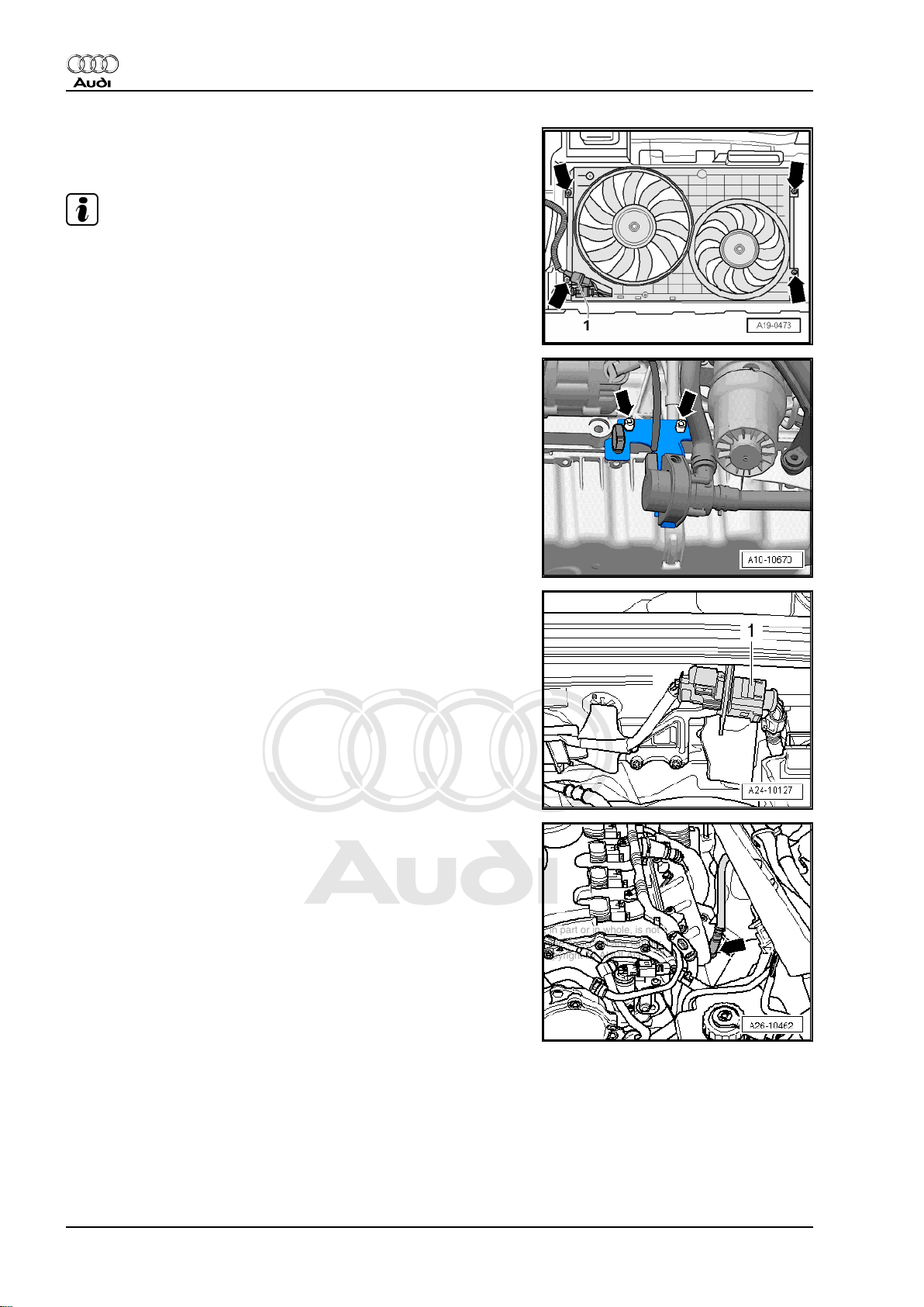
Radiator fan control unit -J293-
1 - Connector for radiator fan control unit -J293-
Note
The radiator fan control unit -J293- is integrated into the radiator
fan -V7- .
Continued coolant circulation pump -V51-
Electrical connector -arrow-
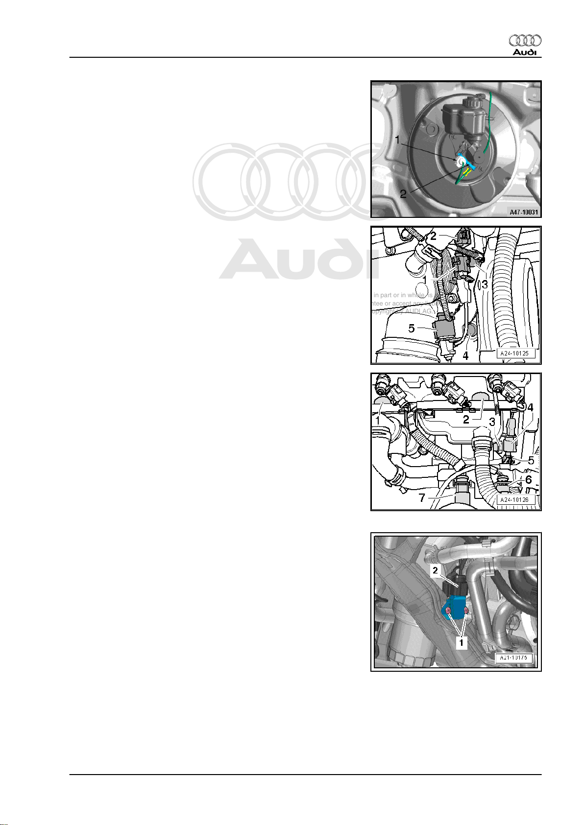
- Lambda probe -G39- and Lambda probe heater -Z19-
Lambda probe -G39- -arrow-
16 Rep. Gr.24 - Mixture preparation - injection
Page 21
Protected by copyright. Copying for private or commercial purposes, in part or in whole, is not
permitted unless authorised by AUDI AG. AUDI AG does not guarantee or accept any liability
with respect to the correctness of information in this document. Copyright by AUDI AG.
Direct petrol injection and ignition system (4-cyl. 2.0 ltr. 4-valve turbo) - Edition 01.2008
Electrical connector -arrow-
- Lambda probe, after catalytic converter -G130- and Lambda
probe heater 1, after catalytic converter -Z29- on right-side un‐
derbody
Lambda probe after catalytic converter -arrow-
- Lambda probe, after catalytic converter -G130- and Lambda
probe heater 1, after catalytic converter -Z29-
Audi TT 2007 ➤
Components on turbocharger “engines with code letters BWA and
BPY”
1 - Removing and installing turbocharger ⇒ Rep. Gr. 21
2 - Tighten charge pressure control solenoid valve -N75- to 3 Nm
3 - Tighten turbocharger air recirculation valve -N249- to 7 Nm
(note installation position, refer to next illustration)
Note installation position of turbocharger air recirculation valve N249- “engines with code letters BWA and BPY”
2. Injection system 17
Page 22

Protected by copyright. Copying for private or commercial purposes, in part or in whole, is not
permitted unless authorised by AUDI AG. AUDI AG does not guarantee or accept any liability
with respect to the correctness of information in this document. Copyright by AUDI AG.
Audi TT 2007 ➤
Direct petrol injection and ignition system (4-cyl. 2.0 ltr. 4-valve turbo) - Edition 01.2008
Component on turbocharger “engines with code letters CDLA,
CDLB and CDMA”
1 - Removing and installing turbocharger ⇒ Rep. Gr. 21
2 - Tighten charge pressure control solenoid valve -N75- to 3 Nm
Turbocharger air recirculation valve -N249- -2- “engines with code
letters CDLA, CDLB and CDMA”
1 - Activated charcoal filter solenoid valve 1 -N80-
2 - Turbocharger air recirculation valve -N249-
Note installation position of turbocharger air recirculation valve N249- “engines with code letters CDLA, CDLB and CDMA”
The marks -arrows- must align.
18 Rep. Gr.24 - Mixture preparation - injection
Page 23

Protected by copyright. Copying for private or commercial purposes, in part or in whole, is not
permitted unless authorised by AUDI AG. AUDI AG does not guarantee or accept any liability
with respect to the correctness of information in this document. Copyright by AUDI AG.
Audi TT 2007 ➤
Direct petrol injection and ignition system (4-cyl. 2.0 ltr. 4-valve turbo) - Edition 01.2008
Exhaust flap 1 valve -N321-
1 - Electrical connector for exhaust flap 1 valve -N321-
Checking vacuum unit for exhaust flap ⇒ Rep. Gr. 26
2.3 Air cleaner / engine cover panel - exploded view (engines with code letters BWA and BPY)
1 - Air mass meter -G70-
❑ Removing and installing
⇒ page 22
2 - 3 Nm
3 - Air cleaner housing (top
section/engine cover panel)
❑ Clean any salt deposits
or leaves and dirt out of
air cleaner housing (top
section)
4 - Spring-type clip
5 - Intake air duct
❑ To air cleaner housing
❑ Clean any leaves and
dirt out of intake air duct
6 - Filter element
❑ Always use genuine
part for air filter element
❑ Removing and installing
⇒ page 20
❑ Observe change inter‐
vals ⇒ Maintenance ;
Booklet 810
7 - Air cleaner housing (bottom
section)
❑ Clean any salt deposits
or leaves and dirt out of
air cleaner housing (bot‐
tom section)
8 - 3 Nm
9 - Heat shield
10 - Rubber sleeve
❑ Note assembly markings
11 - Air hose
❑ Note assembly markings
❑ To turbocharger
❑ Check air intake hose for dirt and leaves
2. Injection system 19
Page 24

Protected by copyright. Copying for private or commercial purposes, in part or in whole, is not
permitted unless authorised by AUDI AG. AUDI AG does not guarantee or accept any liability
with respect to the correctness of information in this document. Copyright by AUDI AG.
Audi TT 2007 ➤
Direct petrol injection and ignition system (4-cyl. 2.0 ltr. 4-valve turbo) - Edition 01.2008
2.4 Removing and installing engine cover panel with air filter element - engines with code letters BWA and BPY
The air filter element is integrated in the engine cover panel.
Removing engine cover panel
– Unplug electrical connector -3- at air mass meter -G70- .
– Open clamps -1 and 2- and disconnect air intake hose from
air mass meter.
– Detach air intake connection at lock carrier -5-.
– Release spring-type clip -4- and detach air intake hose from
engine cover panel.
– Carefully pull engine cover panel off positions -1 - 2 - 3 - 4-
one after the other.
Caution
Always observe sequence (risk of breaking engine cover pan‐
el).
– Cover open intake hose with a clean cloth.
Removing air filter element
– Remove all bolts -arrows-.
– Unbolt heat shield.
20 Rep. Gr.24 - Mixture preparation - injection
Page 25

Protected by copyright. Copying for private or commercial purposes, in part or in whole, is not
permitted unless authorised by AUDI AG. AUDI AG does not guarantee or accept any liability
with respect to the correctness of information in this document. Copyright by AUDI AG.
Direct petrol injection and ignition system (4-cyl. 2.0 ltr. 4-valve turbo) - Edition 01.2008
– Open engine cover panel (note retainers -arrows-).
– Pull air filter element out of engine cover panel.
Installing air filter element
Note
♦
Always use genuine part for air filter element.
♦
Hose connections and hoses for charge air system must be
free of oil and grease before assembly. Do not use any lubri‐
cants containing silicone when assembling.
♦
The air cleaner housing must be clean.
♦
Secure all hose connections with the correct type of hose clips
(same as original equipment): ⇒ Parts catalogue
♦
To prevent malfunctions, cover all critical parts of the engine
air intake tract (air mass meter, intake pipes, etc.) with a clean
cloth when blowing out the air cleaner housing with com‐
pressed air.
♦
Please observe requirements for disposal.
Audi TT 2007 ➤
– Check for salt residue, dirt and leaves in air mass meter and
air intake hose (engine intake side).
– Check for dirt in air intake hose from air duct.
– When installing the air filter element, check that it is properly
centred in the retainer in the air cleaner (bottom section).
– Fit the top section of the air cleaner carefully on the bottom
section, without using force. Make sure the top section of the
air cleaner is fitted straight on the air filter element (note posi‐
tion of sealing lip on air filter element).
– Ensure secure fit of intake hose at air mass meter -G70- .
The remaining installation steps are carried out in the reverse se‐
quence.
2. Injection system 21
Page 26

Protected by copyright. Copying for private or commercial purposes, in part or in whole, is not
permitted unless authorised by AUDI AG. AUDI AG does not guarantee or accept any liability
with respect to the correctness of information in this document. Copyright by AUDI AG.
Audi TT 2007 ➤
Direct petrol injection and ignition system (4-cyl. 2.0 ltr. 4-valve turbo) - Edition 01.2008
2.5 Removing and installing air mass meter
-G70- - engines with code letters BWA
and BPY
– Unplug electrical connector -3- at air mass meter -G70- .
– Unscrew both bolts from air mass meter -G70- and carefully
pull air mass meter -G70- out of guide on air cleaner housing.
Installing
To ensure the proper function of the air mass meter -G70- it is
important to observe the following notes and instructions.
Note
♦
If the air filter element is very dirty or wet, dirt or water could
reach the air mass meter -G70- and affect the air mass value.
This would lead to loss of power, since a smaller injection
quantity is calculated.
♦
Always use genuine part for air filter element.
♦
Use a silicone-free lubricant when installing the intake hose.
♦
Secure all hose connections with the correct type of hose clips
(same as original equipment): ⇒ Parts catalogue
– Check for salt residue, dirt and leaves in air mass meter and
air intake hose (engine intake side).
– Check for dirt in air duct leading to air filter element. If neces‐
sary, clean salt residue, dirt and leaves out of air cleaner
housing (top and bottom sections); wash out or use a vacuum
cleaner as required. Removing and installing air cleaner
⇒ page 20
The remaining installation steps are carried out in the reverse se‐
quence.
22 Rep. Gr.24 - Mixture preparation - injection
Page 27

Protected by copyright. Copying for private or commercial purposes, in part or in whole, is not
permitted unless authorised by AUDI AG. AUDI AG does not guarantee or accept any liability
with respect to the correctness of information in this document. Copyright by AUDI AG.
Audi TT 2007 ➤
Direct petrol injection and ignition system (4-cyl. 2.0 ltr. 4-valve turbo) - Edition 01.2008
2.6 Air cleaner - exploded view (engines with code letters CDLA, CDLB and CDMA)
1 - Gasket
❑ Clipped into air cleaner
housing (bottom sec‐
tion)
2 - Front air duct
❑ Clean out dirt, leaves
and salt deposits
3 - Bolt
❑ 2 Nm
4 - Lower part of air duct
❑ Clean out dirt, leaves
and salt deposits
5 - Air duct cover
6 - Bolt
❑ 5 Nm
7 - Bolt
❑ 3 Nm
8 - Air hose
9 - Air mass meter -G70-
❑ Removing and installing
⇒ page 26
10 - Seal
❑ Renew if damaged
11 - Air cleaner housing (top
section)
❑ Clean any salt deposits
or leaves and dirt out of
air cleaner housing (top
section)
12 - Air filter element
❑ Removing and installing ⇒ page 24
❑ Always use genuine part for air filter element
❑ Observe change intervals ⇒ Maintenance ; Booklet 810
13 - Air cleaner housing (bottom section)
❑ Clean any salt deposits or leaves and dirt out of air cleaner housing (bottom section)
❑ Removing and installing ⇒ page 25
❑ Clean out dirt, leaves and salt deposits
14 - Bolt
❑ 10 Nm
15 - Rubber grommet
16 - Bolt
❑ 10 Nm
17 - Bracket for air cleaner housing
18 - Retaining peg
❑ 10 Nm
2. Injection system 23
Page 28

Protected by copyright. Copying for private or commercial purposes, in part or in whole, is not
permitted unless authorised by AUDI AG. AUDI AG does not guarantee or accept any liability
with respect to the correctness of information in this document. Copyright by AUDI AG.
Audi TT 2007 ➤
Direct petrol injection and ignition system (4-cyl. 2.0 ltr. 4-valve turbo) - Edition 01.2008
19 - Rubber grommet
2.7 Removing and installing engine cover panel - engines with code letters CDLA, CDLB and CDMA
Removing
– Carefully pull off engine cover panel -arrows-. Do not jerk the
cover panel away, and do not try to pull on one side only.
Installing
– Press engine cover panel back carefully into its retainers.
– To avoid damage, do not strike the engine cover panel with
your fist or with any kind of tool.
2.8 Removing and installing air filter ele‐
ment - engines with code letters CDLA,
CDLB and CDMA
Removing
– Detach air intake hose -1- at air mass meter -G70- .
– Unplug electrical connector -2- at air mass meter -G70- .
– Detach air cleaner housing (top section) -arrows- and take out
air filter element.
Installing
Installation is carried out in the reverse order; note the following:
To ensure the proper function of the air mass meter it is important
to observe the following notes and instructions.
Note
♦
If the air filter element is very dirty or wet, dirt or water could
reach the air mass meter and affect the air mass value. This
would lead to loss of power, since a smaller injection quantity
is calculated.
♦
Always use genuine part for air filter element.
♦
The air cleaner housing MUST be clean.
♦
Secure all hose connections with the correct type of hose clips
(same as original equipment) ⇒ Electronic parts catalogue .
♦
To prevent malfunctions, cover all critical parts of the engine
air intake tract (air mass meter, intake pipes, etc.) with a clean
cloth when blowing out the air cleaner housing with com‐
pressed air.
♦
Please observe requirements for disposal.
24 Rep. Gr.24 - Mixture preparation - injection
Page 29

Protected by copyright. Copying for private or commercial purposes, in part or in whole, is not
permitted unless authorised by AUDI AG. AUDI AG does not guarantee or accept any liability
with respect to the correctness of information in this document. Copyright by AUDI AG.
Direct petrol injection and ignition system (4-cyl. 2.0 ltr. 4-valve turbo) - Edition 01.2008
– Blow out water drain (small hole in bottom section of air clean‐
er housing) with compressed air.
– Clean salt residue, dirt and leaves out of air cleaner housing
(top and bottom sections); use a vacuum cleaner if necessary.
– Check for salt residue, dirt and leaves in air mass meter and
air intake hose (engine intake side).
– Check for dirt and leaves in air duct going from lock carrier to
air cleaner housing.
– When installing the air filter element, check that it is properly
centred in the retainer in the air cleaner housing (bottom sec‐
tion).
– Fit the top section of the air cleaner housing carefully on the
bottom section, without using force. Make sure the top section
of the air cleaner housing is fitted straight on the air filter ele‐
ment (note position of sealing lip on air filter element).
– Ensure secure fit of intake hose at air mass meter.
♦ Tightening torque: refer to air cleaner - exploded view
⇒ page 23
Audi TT 2007 ➤
2.9 Removing and installing air cleaner housing - engines with code letters CDLA, CDLB and CDMA
Removing
– Remove air filter element ⇒ page 24 .
– Unscrew bolts -arrows- and remove air duct.
– Unscrew air cleaner housing (lower section) -arrows-.
Installing
Installation is carried out in the reverse order; note the following.
Note
♦
The air cleaner housing MUST be clean.
♦
Secure all hose connections with the correct type of hose clips
(same as original equipment) ⇒ Electronic parts catalogue .
♦
To prevent malfunctions, cover all critical parts of the engine
air intake tract (air mass meter, intake pipes, etc.) with a clean
cloth when blowing out the air cleaner housing with com‐
pressed air.
2. Injection system 25
Page 30

Protected by copyright. Copying for private or commercial purposes, in part or in whole, is not
permitted unless authorised by AUDI AG. AUDI AG does not guarantee or accept any liability
with respect to the correctness of information in this document. Copyright by AUDI AG.
Audi TT 2007 ➤
Direct petrol injection and ignition system (4-cyl. 2.0 ltr. 4-valve turbo) - Edition 01.2008
– Blow out water drain (small hole in bottom section of air clean‐
er housing) with compressed air.
– Clean salt residue, dirt and leaves out of air cleaner housing
(top and bottom sections); use a vacuum cleaner if necessary.
– Check for salt residue, dirt and leaves in air mass meter and
air intake hose (engine intake side).
– Check for dirt and leaves in air duct going from lock carrier to
air cleaner housing.
– Fit the top section of the air cleaner housing carefully on the
bottom section, without using force. Make sure the top section
of the air cleaner housing is fitted straight on the air filter ele‐
ment (note position of sealing lip on air filter element).
♦ Tightening torque: refer to air cleaner - exploded view
⇒ page 23
2.10 Removing and installing air mass meter
-G70- - engines with code letters CDLA,
CDLB and CDMA
Removing
– Detach electrical connector -2- for air mass meter -G70- .
Note
Disregard arrows.
– Loosen hose clip -1- and detach air intake hose.
26 Rep. Gr.24 - Mixture preparation - injection
Page 31

Protected by copyright. Copying for private or commercial purposes, in part or in whole, is not
permitted unless authorised by AUDI AG. AUDI AG does not guarantee or accept any liability
with respect to the correctness of information in this document. Copyright by AUDI AG.
Direct petrol injection and ignition system (4-cyl. 2.0 ltr. 4-valve turbo) - Edition 01.2008
– Remove bolts -arrows-.
– Then carefully pull air mass meter -G70- out of guide on air
cleaner housing (top section).
Installing
• Tightening torque ⇒ page 23
Installation is carried out in the reverse order; note the following.
To ensure the proper function of the air mass meter it is important
to observe the following notes and instructions.
Note
♦
Renew O-ring.
♦
If the air filter element is very dirty or wet, dirt or water could
reach the air mass meter and affect the air mass value. This
would lead to loss of power, since a smaller injection quantity
is calculated.
♦
Always use genuine part for air filter element.
♦
Use silicone-free lubricant when fitting air intake hose.
♦
Secure all hose connections with the correct type of hose clips
(same as original equipment) ⇒ Electronic parts catalogue .
Audi TT 2007 ➤
2. Injection system 27
Page 32

Protected by copyright. Copying for private or commercial purposes, in part or in whole, is not
permitted unless authorised by AUDI AG. AUDI AG does not guarantee or accept any liability
with respect to the correctness of information in this document. Copyright by AUDI AG.
Audi TT 2007 ➤
Direct petrol injection and ignition system (4-cyl. 2.0 ltr. 4-valve turbo) - Edition 01.2008
2.11 Intake manifold - exploded view
1 - Screw for intake air temper‐
ature sender -G42-
❑ 5 Nm
2 - Intake air temperature
sender -G42-
3 - Intake manifold
❑ Removing and installing
⇒ page 31
4 - Activated charcoal filter sol‐
enoid valve 1 -N80-
5 - Bolt for single-plunger highpressure pump
❑ 3 x
❑ 10 Nm
6 - Fuel pressure regulating
valve -N276-
7 - Mechanical single-plunger
high-pressure pump
❑ With fuel pressure regu‐
lating valve -N276- and
fuel pressure sender,
low pressure -G410-
❑ An electric fuel pump
(fitted in fuel tank) sup‐
plies fuel to the mechan‐
ical high-pressure pump
at a pressure of approx.
6 bar.
❑ When installing the
high-pressure fuel
pump, it is essential to
ensure that no dirt en‐
ters the fuel system.
❑ The fuel system must
not be under pressure; procedure for reducing fuel pressure ⇒ page 4
❑ Fuel pipes must be free of tension when installed.
❑ Removing and installing ⇒ page 42
8 - Connection for fuel return pipe to fuel tank
❑ Fuel pipe must be free of tension when installed (make sure all parts are clean)
9 - Fuel supply pipe to fuel rail
❑ Renew connecting piece
❑ Tighten connecting piece to 30 Nm
❑ Fuel line must be free of tension when installed (make sure all parts are clean); tightening torque: 27 Nm
10 - Intake manifold flap motor -V157- with intake manifold flap potentiometer -G336-
❑ After the fuel rail has been renewed, intake manifold flap potentiometer -G336- must be adapted to the
engine control unit with the vehicle diagnostic and service information system -VAS 5052- , “Guided
Functions”
❑ Removing and installing ⇒ page 49
11 - Bolt for intake manifold flap motor -V157- with intake manifold flap potentiometer -G336-
❑ 7 Nm
28 Rep. Gr.24 - Mixture preparation - injection
Page 33

Protected by copyright. Copying for private or commercial purposes, in part or in whole, is not
permitted unless authorised by AUDI AG. AUDI AG does not guarantee or accept any liability
with respect to the correctness of information in this document. Copyright by AUDI AG.
Audi TT 2007 ➤
Direct petrol injection and ignition system (4-cyl. 2.0 ltr. 4-valve turbo) - Edition 01.2008
12 - Intake manifold support
13 - Bolt for intake manifold support
❑ 23 Nm
14 - Throttle valve module -J338- , throttle valve drive for electric throttle -G186-
❑ Throttle valve drive angle sender 1 for electric throttle -G187- and throttle valve drive angle sender 2 for
electric throttle -G188-
❑ After the throttle valve module -J338- has been renewed, it must be adapted to the engine control unit -
J623- , see vehicle diagnostic and service information system -VAS 5052- “Guided Functions”
15 - Bolt for throttle valve module -J338-
❑ 4 x
❑ 7 Nm
16 - Securing nut for intake manifold support
❑ 10 Nm
17 - Seal
❑ Renew
18 - Fuel rail
❑ Removing and installing ⇒ page 31
19 - Fuel pressure sender -G247-
❑ 20 Nm
2. Injection system 29
Page 34

Protected by copyright. Copying for private or commercial purposes, in part or in whole, is not
permitted unless authorised by AUDI AG. AUDI AG does not guarantee or accept any liability
with respect to the correctness of information in this document. Copyright by AUDI AG.
Audi TT 2007 ➤
Direct petrol injection and ignition system (4-cyl. 2.0 ltr. 4-valve turbo) - Edition 01.2008
2.12 Fuel rail - exploded view
1 - Radial compensation ele‐
ment
❑ Renew if damaged
2 - Injector
❑ With combustion cham‐
ber ring seal (teflon ring
seal): always renew
❑ Renew O-rings
❑ Ensure correct installa‐
tion position.
❑ Removing and installing
⇒ page 44
3 - Support ring
4 - Fuel rail
❑ Removing and installing
⇒ page 31
5 - Fuel pressure sender G247-
❑ 22 Nm
❑ Tighten connecting
piece to 30 Nm
6 - Fuel pressure sender for
low pressure -G410-
7 - Fuel pressure regulating
valve -N276-
8 - Mechanical single-plunger
high-pressure pump
❑ With fuel pressure regu‐
lating valve -N276- and
fuel pressure sender,
low pressure -G410❑ An electric fuel pump
(fitted in fuel tank) sup‐
plies fuel to the mechanical high-pressure pump at a pressure of approx. 6 bar.
❑ When installing the high-pressure fuel pump, it is essential to ensure that no dirt enters the fuel system.
❑ The fuel system must not be under pressure when installing the high-pressure pump; procedure for
reducing fuel pressure ⇒ page 4
❑ Fuel pipes must be free of tension when installed.
❑ Removing and installing ⇒ page 42
9 - Activated charcoal filter solenoid valve 1 -N80-
10 - Throttle valve module -J338- , throttle valve drive for electric throttle -G186-
❑ Throttle valve drive angle sender 1 for electric throttle -G187- and throttle valve drive angle sender 2 for
electric throttle -G188❑ After the throttle valve module -J338- has been renewed, it must be adapted to the engine control unit -
J623- , see vehicle diagnostic and service information system -VAS 5052- “Guided Functions”
11 - Intake air temperature sender 2 -G299-
❑ 5 Nm
12 - Bolts for intake manifold
❑ 9 Nm
30 Rep. Gr.24 - Mixture preparation - injection
Page 35

Protected by copyright. Copying for private or commercial purposes, in part or in whole, is not
permitted unless authorised by AUDI AG. AUDI AG does not guarantee or accept any liability
with respect to the correctness of information in this document. Copyright by AUDI AG.
Direct petrol injection and ignition system (4-cyl. 2.0 ltr. 4-valve turbo) - Edition 01.2008
13 - Intake manifold
❑ Removing and installing ⇒ page 31
2.13 Removing and installing intake manifold with fuel rail
After the fuel rail has been renewed, intake manifold flap poten‐
tiometer -G336- must be adapted to the engine control unit J623- , see vehicle diagnostic and service information system VAS 5052- , “Guided Functions”
Note
♦
The injectors can only be accessed after removal of the intake
manifold and fuel rail with air flow control flap. (Additional or
fewer steps may be required depending on the model.)
♦
The combustion chamber (teflon) ring seal and the O-ring
must always be renewed.
♦
Intake manifold - exploded view ⇒ page 28
♦
Fuel rail - exploded view ⇒ page 30
Audi TT 2007 ➤
Removing
– Remove engine cover panel.
WARNING
The fuel system is pressurised. The fuel pressure in the highpressure part of the injection system must be reduced to a
residual pressure prior to opening; for procedure see
⇒ page 4 .
– Unplug all electrical connectors as necessary.
– Disconnect vacuum hose between intake manifold and vac‐
uum pump at intake manifold.
Note
♦
This vacuum hose and the vacuum pump (located at rear of
cylinder head) are only fitted on vehicles with automatic gear‐
box.
♦
Ignore items marked 1 and 2 in illustration.
– Disconnect hose connections -arrows- at cylinder head cover.
2. Injection system 31
Page 36

Protected by copyright. Copying for private or commercial purposes, in part or in whole, is not
permitted unless authorised by AUDI AG. AUDI AG does not guarantee or accept any liability
with respect to the correctness of information in this document. Copyright by AUDI AG.
Audi TT 2007 ➤
Direct petrol injection and ignition system (4-cyl. 2.0 ltr. 4-valve turbo) - Edition 01.2008
– Disconnect vacuum line -2- leading to activated charcoal filter.
– Disconnect fuel supply pipe -arrow-.
Note
The fuel system must not be under pressure.
– Open both fuel pipe connections -2 and 3- at high-pressure
pump.
– Unscrew bolt and nut -arrows- and press coolant pipe (front
right) to one side (coolant hoses remain attached).
32 Rep. Gr.24 - Mixture preparation - injection
Page 37

Protected by copyright. Copying for private or commercial purposes, in part or in whole, is not
permitted unless authorised by AUDI AG. AUDI AG does not guarantee or accept any liability
with respect to the correctness of information in this document. Copyright by AUDI AG.
Direct petrol injection and ignition system (4-cyl. 2.0 ltr. 4-valve turbo) - Edition 01.2008
– Remove bolt -arrow- for dipstick guide tube.
Step required only for engines with code letters CDLA, CDLB and
CDMA
– Unplug electrical connector -3-.
– Remove bolt -arrow-.
– Detach hose -2-.
– Loosen hose clip -1-, pull turbocharger air recirculation valve
-N249- off air pipe and move clear (hose -4- remains connec‐
ted).
All engine codes
Audi TT 2007 ➤
– Loosen hose clip -2- and detach air pipe from throttle valve
module -J338- .
Note
Disregard -items 1, 3 and 4-.
– Unplug electrical connector -1- at intake air temperature send‐
er -G42- .
Note
Ignore -arrow-.
2. Injection system 33
Page 38

Protected by copyright. Copying for private or commercial purposes, in part or in whole, is not
permitted unless authorised by AUDI AG. AUDI AG does not guarantee or accept any liability
with respect to the correctness of information in this document. Copyright by AUDI AG.
Audi TT 2007 ➤
Direct petrol injection and ignition system (4-cyl. 2.0 ltr. 4-valve turbo) - Edition 01.2008
– Unplug electrical connectors:
2 - For injectors (remove electrical connectors from bracket)
3 - For activated charcoal filter solenoid valve 1 -N80-
4 - Intake manifold flap motor -V157-
5 - For fuel pressure sender -G247- and Hall sender -G40- (re‐
move electrical connectors from bracket)
– Unplug electrical connector -1-.
– Remove bolts -arrows- and detach throttle valve module -
J338- .
– Unscrew nut -2- and bolt -1- and remove support for intake
manifold.
– Unplug electrical connector -1- at fuel pressure sender -
G247- .
– Unscrew all bolts from intake manifold.
– Carefully pull intake manifold and fuel rail off cylinder head.
Note
The injectors can remain in the fuel rail.
– Removing and installing fuel rail ⇒ page 35
Installing
– Install in reverse order.
♦ Tightening torques: refer to intake manifold - exploded view
⇒ page 28
♦ Tightening torques: refer to fuel rail - exploded view
⇒ page 30
34 Rep. Gr.24 - Mixture preparation - injection
Page 39

Protected by copyright. Copying for private or commercial purposes, in part or in whole, is not
permitted unless authorised by AUDI AG. AUDI AG does not guarantee or accept any liability
with respect to the correctness of information in this document. Copyright by AUDI AG.
Direct petrol injection and ignition system (4-cyl. 2.0 ltr. 4-valve turbo) - Edition 01.2008
2.13.1 Removing and installing fuel rail
If the fuel rail has been renewed, intake manifold flap potentiom‐
eter -G336- must be adapted to the engine control unit -J623- ,
see vehicle diagnostic and service information system -VAS
5052- , “Guided Functions”
Note
Intake manifold must be removed; removing intake manifold
⇒ page 31 .
– Remove hoses from activated charcoal filter.
– To do this, unfasten hose clip -1-.
– Unscrew two bolts -arrows- on fuel rail.
– Detach hose connection -1- from intake manifold and unscrew
two bolts -arrows-.
Audi TT 2007 ➤
– Disconnect fuel pipes -2 and 3-.
– Carefully pry off linkage from intake manifold flap motor -V157-
-4-.
– Unbolt intake manifold flap motor -V157- -5-.
2. Injection system 35
Page 40

Protected by copyright. Copying for private or commercial purposes, in part or in whole, is not
permitted unless authorised by AUDI AG. AUDI AG does not guarantee or accept any liability
with respect to the correctness of information in this document. Copyright by AUDI AG.
Audi TT 2007 ➤
Direct petrol injection and ignition system (4-cyl. 2.0 ltr. 4-valve turbo) - Edition 01.2008
– Pry fuel rail over retaining lugs -arrows- on intake manifold.
– Pull fuel rail off intake manifold.
Installing
– Install in reverse order.
– Installing intake manifold ⇒ page 31
2.14 Removing and installing fuel pressure sender -G247-
Special tools and workshop equipment required
♦ Assembly tool -T10118-
♦ Double hexagon socket, 27 mm -VAS 5301/7-
Removing:
WARNING
The fuel system is pressurised. The fuel pressure in the highpressure part of the injection system must be reduced to a
residual pressure prior to opening; for procedure see
⇒ page 4 .
36 Rep. Gr.24 - Mixture preparation - injection
Page 41

Protected by copyright. Copying for private or commercial purposes, in part or in whole, is not
permitted unless authorised by AUDI AG. AUDI AG does not guarantee or accept any liability
with respect to the correctness of information in this document. Copyright by AUDI AG.
Direct petrol injection and ignition system (4-cyl. 2.0 ltr. 4-valve turbo) - Edition 01.2008
– Detach coolant pipe and dipstick guide tube from intake mani‐
fold -arrows- and pull dipstick guide tube upwards off engine.
– Release connector on fuel pressure sender -G247- using as‐
sembly tool -T10118- .
– Unscrew fuel pressure sender -G247- using double hexagon
socket, 27 mm -VAS 5301/7- .
Installing:
– Install in reverse order.
– Make sure that connecting piece is tightened to specified tor‐
que “30 Nm” before installing fuel pressure sender -G247- .
♦ Tightening torque for fuel pressure sender -G247- , refer to
fuel rail - exploded view ⇒ page 30 .
Audi TT 2007 ➤
2.15 Checking fuel pressure (low pressure) up to high-pressure pump
Note
♦
Control unit for electric fuel pump OK.
♦
Fuel pump OK.
♦
Fuel filter OK
♦
Battery voltage at least 11 Volt
– Switch on ignition.
– Connect vehicle diagnosis and service information system -
VAS 5052- and select engine control unit.
– Select “Engine electronics” in vehicle self-diagnosis.
– Then select function read “Measured values”.
– Select measured value block 103.
– With ignition on, the fuel pressure (low pressure) is indicated
in display zone 1.
Note
When the ignition is switched off and on, the control unit for the
electric fuel pump -J538- will activate the fuel pump for several
seconds.
– Measure the fuel pressure (low pressure).
♦ Specification: approx. 6 bar (5 ... 7 bar)
2. Injection system 37
Page 42

Protected by copyright. Copying for private or commercial purposes, in part or in whole, is not
permitted unless authorised by AUDI AG. AUDI AG does not guarantee or accept any liability
with respect to the correctness of information in this document. Copyright by AUDI AG.
Audi TT 2007 ➤
Direct petrol injection and ignition system (4-cyl. 2.0 ltr. 4-valve turbo) - Edition 01.2008
– If reading does not match specification, check delivery rate of
electric fuel pump ⇒ Rep. Gr. 20 .
– Check fuel pressure and residual pressure using K-Jetronic
pressure tester -V.A.G 1318- ⇒ page 38 .
2.16 Checking fuel pressure and residual pressure (up to high-pressure pump)
Special tools and workshop
equipment required
♦ K-Jetronic pressure tester -
V.A.G 1318-
♦ Adapter -V.A.G 1318/11-
♦ Adapter -V.A.G 1318/17-1-
from adapter set -V.A.G
1318/17-
♦ Connector -V.A.G 1318/23-
♦ Remote control -V.A.G
1348/3 A- with adapter ca‐
ble -V.A.G 1348/3-3-
♦ Auxiliary measuring set -
V.A.G 1594 C- or -V.A.G
1594 A-
♦ Fuel-resistant measuring
container
Test conditions
• Battery voltage at least 12.5 V
• Fuel filter OK
•
Fuel tank at least 1/4 full.
• Fuel pump control unit -J538- OK (check)
• Ignition off.
38 Rep. Gr.24 - Mixture preparation - injection
Page 43

Protected by copyright. Copying for private or commercial purposes, in part or in whole, is not
permitted unless authorised by AUDI AG. AUDI AG does not guarantee or accept any liability
with respect to the correctness of information in this document. Copyright by AUDI AG.
Direct petrol injection and ignition system (4-cyl. 2.0 ltr. 4-valve turbo) - Edition 01.2008
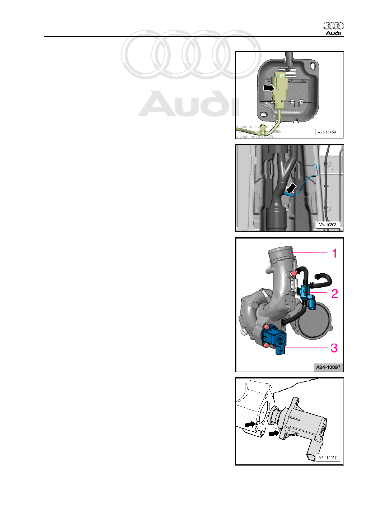
Test sequence
– Remove rear seat ⇒ General body repairs, interior; Rep. Gr.
72 .
– Unclip the retaining tabs -arrows- for the flange cover.
– Unplug electrical connector -arrow- at flange.
Audi TT 2007 ➤
– Connect remote control -V.A.G 1348/3 A- with adapter cable
-V.A.G 1348/3-3- to contact -1- using a test lead from auxiliary
measuring set -V.A.G 1594 C- .
– Tape off 2nd connector contact of the adapter cable -
V.A.G 1348/3-3- with insulating tape -arrow- to prevent short
circuits.
– Connect contact -5- to the body (earth) using a test lead from
auxiliary measuring set -V.A.G 1594 C- .
– Connect crocodile clamp to positive (+) terminal of battery.
– Remove filler cap from fuel filler neck.
WARNING
Fuel system is pressurised (low pressure). Wear safety gog‐
gles and protective clothing to avoid possible injury and skin
contact. Before opening the fuel system, wrap a cloth around
the connection. Then dissipate residual pressure by carefully
detaching the connection.
– Disconnect fuel supply pipe -arrow-.
2. Injection system 39
Page 44

Protected by copyright. Copying for private or commercial purposes, in part or in whole, is not
permitted unless authorised by AUDI AG. AUDI AG does not guarantee or accept any liability
with respect to the correctness of information in this document. Copyright by AUDI AG.
Audi TT 2007 ➤
Direct petrol injection and ignition system (4-cyl. 2.0 ltr. 4-valve turbo) - Edition 01.2008
– Screw connector -V.A.G 1318/23- and adapter -
V.A.G 1318/17-1- onto K-Jetronic tester -V.A.G 1318- .
– Fit adapter -V.A.G 1318/17-1- onto the disconnected fuel sup‐
ply pipe.
– Screw adapter -V.A.G 1318/11- onto K-Jetronic tester -V.A.G
1318- .
– Attach test hose -arrow- and hold end of hose in measuring
container.
– Open cut-off valve on K-Jetronic pressure tester -V.A.G
1318- . Lever must point in direction of flow.
– Bleed fuel system by pressing remote control button briefly.
– Close cut-off valve on K-Jetronic pressure tester -V.A.G
1318- . Lever is at right angle to direction of flow -arrow-.
– Press and hold remote control switch until K-Jetronic pressure
tester -V.A.G 1318- shows no further increase in pressure.
• Specification: approx. 6 bar (4 ...8 bar)
If specification is not obtained:
– Check delivery rate of fuel pump ⇒ Fuel supply system, petrol
engines; Rep. Gr. 20 .
Checking residual pressure
– Check leak-tightness and residual pressure by watching the
drop in pressure on the K-Jetronic pressure tester -V.A.G
1318- .
• After 10 minutes pressure should still be at least 3 bar.
If the residual pressure drops below 3 bar:
♦ Check union between K-Jetronic pressure tester -V.A.G 1318-
and fuel supply line for leaks.
♦ Check K-Jetronic pressure tester -V.A.G 1318- for leaks.
♦ Check fuel lines and their connections for leaks.
♦ Renew fuel filter with integrated fuel pressure regulator ⇒ Fuel
supply system, petrol engines; Rep. Gr. 20 . Then repeat the
test.
♦ If fuel filter is OK, renew fuel pump ⇒ Fuel supply system,
petrol engines; Rep. Gr. 20 .
Assembly is carried out in the reverse order; note the following:
– The ignition must be switched off.
Note
Before removing the pressure tester, release the fuel pressure by
opening the cut-off valve. Hold auxiliary hose in a container.
– Re-attach fuel supply line (make sure that all parts are clean
and that there are no leaks).
40 Rep. Gr.24 - Mixture preparation - injection
Page 45

Protected by copyright. Copying for private or commercial purposes, in part or in whole, is not
permitted unless authorised by AUDI AG. AUDI AG does not guarantee or accept any liability
with respect to the correctness of information in this document. Copyright by AUDI AG.
Audi TT 2007 ➤
Direct petrol injection and ignition system (4-cyl. 2.0 ltr. 4-valve turbo) - Edition 01.2008
2.17 High-pressure pump - exploded view
WARNING
Fuel system operates under high pressure. Always dissipate
fuel pressure prior to opening fuel system. For procedure, refer
to ⇒ page 4
1 - Air guide plates
❑ Removable
❑ Check for damage and
correct fitting
2 - Sleeve
❑ May remain lodged in
cylinder head when
high-pressure pump is
removed; it can be re‐
moved
3 - O-ring
❑ Renew
4 - Mechanical single-plunger
high-pressure pump
❑ An electric fuel pump
(fitted in fuel tank) sup‐
plies fuel to the mechan‐
ical high-pressure pump
at a pressure of approx.
6 bar.
❑ When installing the
high-pressure fuel
pump, it is essential to
ensure that no dirt en‐
ters the fuel system.
❑ The fuel system must
not be under pressure;
procedure for reducing
fuel pressure ⇒ page 4
❑ Fuel pipes must be free
of tension when instal‐
led.
❑ Removing and installing
⇒ page 42
5 - Fuel pressure regulating
valve -N276-
6 - Fuel pressure sender for low pressure -G410-
❑ 15 Nm
7 - Securing bolts for high-pressure pump
❑ 10 Nm
8 - Connecting piece for fuel return pipe to fuel tank
❑ It is important to leave the old seal in the pump when replacing the threaded connection. When it is first
installed at the supplier it becomes crushed and cannot be removed. For this reason, the threaded con‐
nection has a deformable sealing lip.
9 - Connecting piece for fuel supply pipe to fuel rail
❑ Renew connecting piece
2. Injection system 41
Page 46

Protected by copyright. Copying for private or commercial purposes, in part or in whole, is not
permitted unless authorised by AUDI AG. AUDI AG does not guarantee or accept any liability
with respect to the correctness of information in this document. Copyright by AUDI AG.
Audi TT 2007 ➤
Direct petrol injection and ignition system (4-cyl. 2.0 ltr. 4-valve turbo) - Edition 01.2008
❑ Tighten connecting piece to 30 Nm
❑ Union nut on fuel supply line must be free of tension when installed (make sure all parts are clean);
tightening torque: 27 Nm
10 - Bore in cylinder head for high-pressure pump
11 - Injectors
❑ Renew O-rings
❑ Ensure correct installation position.
❑ Removing and installing ⇒ page 44
2.18 Removing and installing high-pressure pump
WARNING
Fuel system operates under high pressure. Always dissipate
fuel pressure prior to opening fuel system. For procedure, refer
to ⇒ page 4
If the battery is not disconnected, the fuse -SF 6- for the fuel pump
control unit -J538- must be removed as a precautionary measure
before opening the fuel system, because the fuel pump will oth‐
erwise be activated by the contact switch on the driver's door.
Note
♦
The fuse is located in the fuse holder in the luggage compart‐
ment (right-side).
♦
Removing fuse -SF 6- will interrupt the voltage supply “termi‐
nal 30” for the fuel pump control unit -J538- .
Note
♦
The high-pressure fuel pump should only be removed and in‐
stalled when the engine is cold.
♦
When installing the high-pressure fuel pump, it is essential to
ensure that no dirt enters the fuel system.
♦
Use a cloth to catch escaping fuel.
♦
The O-ring must always be renewed.
♦
Banjo bolt for fuel return line must always be renewed.
♦
Always ensure that the high-pressure fuel pipes are free of
tension when tightening the connections.
Removing
– Remove engine cover panel.
42 Rep. Gr.24 - Mixture preparation - injection
Page 47

Protected by copyright. Copying for private or commercial purposes, in part or in whole, is not
permitted unless authorised by AUDI AG. AUDI AG does not guarantee or accept any liability
with respect to the correctness of information in this document. Copyright by AUDI AG.
Direct petrol injection and ignition system (4-cyl. 2.0 ltr. 4-valve turbo) - Edition 01.2008
– Detach electrical connectors from fuel pressure sender (low
pressure) -G410- -1- and fuel pressure regulating valve N276- -2-.
– Disconnect fuel pipes -2 and 3-.
Audi TT 2007 ➤
– Remove 3 bolts -arrows-.
– Carefully pull out high-pressure fuel pump. It is possible that
the sleeve may remain lodged in the cylinder head.
Installing
– Renew O-ring for high-pressure pump.
– Carefully fit high-pressure pump and sleeve in cylinder head
bore (check sleeve for damage first).
– Tighten bolts hand-tight.
– Make sure that connecting pieces on high-pressure pump are
tightened to specified torque before installing fuel lines.
♦ Tightening torque for connecting piece for fuel return line, refer
to high-pressure pump - exploded view ⇒ page 41
♦ Tightening torque for connecting piece for fuel supply line, re‐
fer to high-pressure pump - exploded view ⇒ page 41
– Now tighten bolts to specified torque (it is important to tighten
them alternately).
♦ Tightening torque: refer to exploded view of high-pressure
pump ⇒ page 41 .
– Firmly fit hose for fuel return line onto connection (use hose
clip). Align so that parts are free of tension.
– Tighten union nut on fuel supply line hand-tight. Align so that
parts are free of tension.
♦ Tightening torque for fuel supply line (union nut), refer to high-
pressure pump - exploded view ⇒ page 41 .
2. Injection system 43
Page 48

Protected by copyright. Copying for private or commercial purposes, in part or in whole, is not
permitted unless authorised by AUDI AG. AUDI AG does not guarantee or accept any liability
with respect to the correctness of information in this document. Copyright by AUDI AG.
Audi TT 2007 ➤
Direct petrol injection and ignition system (4-cyl. 2.0 ltr. 4-valve turbo) - Edition 01.2008
– Reattach electrical connectors for fuel pressure sender (low
pressure) -G410- and fuel pressure regulating valve -N276- .
– Put back fuse if it has been removed.
Note
Check fuel system for leaks.
2.19 Removing and installing injectors
Removing
Remove intake manifold and fuel rail ⇒ page 31 .
Removing injectors (from fuel rail)
Carefully pull injectors out of fuel rail.
Removing injectors (from cylinder head)
Special tools and workshop equipment required
♦ Tool kit with puller -T10133-
Note
Special tool T10133/2 (puller) has been modified and now has the
designation puller T10133/2 A . If you have not yet received the
new tool you can make the modification yourself.
Modifying special tool T10133/2 (puller) to make it equivalent to
puller T10133/2 A
Special tools and workshop equipment required
♦ Round file, approx. 6 mm
– File out a semi-circular recess as shown in the illustration. The
recess allows the tool to be pushed further onto the injector so
the contact surface is increased.
44 Rep. Gr.24 - Mixture preparation - injection
Page 49

Protected by copyright. Copying for private or commercial purposes, in part or in whole, is not
permitted unless authorised by AUDI AG. AUDI AG does not guarantee or accept any liability
with respect to the correctness of information in this document. Copyright by AUDI AG.
Direct petrol injection and ignition system (4-cyl. 2.0 ltr. 4-valve turbo) - Edition 01.2008
– For identification purposes, mark the modified tool with the
letter “A” after the tool number.
Illustration shows injector assembly:
1 - Radial compensation element, renew if damaged
2 - Combustion chamber ring seal (teflon ring seal) - renew; when
fitting, do not grease ring or use any other lubricant
3 - Groove on injector
4 - Spacer ring (renew if damaged)
5 - O-ring (renew; apply thin coating of clean engine oil prior to
installation)
6 - Support ring (via this support ring, fuel rail exerts force which
secures injector in cylinder head)
Audi TT 2007 ➤
Note
The radial compensation element -1- is clipped into the support
ring -6- with the injector fitted. To remove the injector, the support
ring must be removed from the injector so that the puller T10133/2- can be inserted into the groove on the injector -3-.
– Cover open inlet ports with a clean cloth.
– Unplug electrical connector at injector that is to be removed.
– Use a screwdriver to bend retainer tabs of radial compensation
element to side, and pull support ring off injector.
2. Injection system 45
Page 50

Protected by copyright. Copying for private or commercial purposes, in part or in whole, is not
permitted unless authorised by AUDI AG. AUDI AG does not guarantee or accept any liability
with respect to the correctness of information in this document. Copyright by AUDI AG.
Audi TT 2007 ➤
Direct petrol injection and ignition system (4-cyl. 2.0 ltr. 4-valve turbo) - Edition 01.2008
– Apply puller -T10133/2A- to groove on injector.
– Then attach removal tool -T10133/16- and pull out injector by
turning bolt -1-.
Note
The combustion chamber ring seal must always be renewed prior
to reinstalling the high-pressure injector ⇒ page 46 .
2.19.1 Renewing combustion chamber ring seal (teflon ring seal)
Note
The combustion chamber ring seal must always be renewed prior
to reinstalling the high-pressure injector.
Illustration shows injector assembly:
1 - Radial compensation element, renew if damaged
2 - Combustion chamber ring seal (teflon ring seal) - renew; when
fitting, do not grease ring or use any other lubricant
3 - Groove on injector
4 - Spacer ring (renew if damaged)
5 - O-ring (renew; apply thin coating of clean engine oil prior to
installation)
6 - Support ring (via this support ring, fuel rail exerts force which
secures injector in cylinder head)
– Carefully remove old teflon ring using suitable tools (e.g. cut
open ring using razor blade, or prise open ring with small
screwdriver and then pull off forwards). It is important to en‐
sure that the groove and the continuous ridge in the bottom of
the groove are not damaged.
Note
The injector must be renewed if the groove is damaged.
– Before new teflon ring is fitted, any combustion residue must
be removed from ring groove and injector stem using a clean
cloth.
Note
The illustration shows an injector with “offset connector”. This can
be ignored since it is not relevant when replacing the combustion
chamber ring seal.
46 Rep. Gr.24 - Mixture preparation - injection
Page 51

Protected by copyright. Copying for private or commercial purposes, in part or in whole, is not
permitted unless authorised by AUDI AG. AUDI AG does not guarantee or accept any liability
with respect to the correctness of information in this document. Copyright by AUDI AG.
Direct petrol injection and ignition system (4-cyl. 2.0 ltr. 4-valve turbo) - Edition 01.2008
– Fit the assembly cone -T10133/5- with new teflon seal -1- onto
the injector -2-.
– Use assembly sleeve -T10133/6- to press teflon ring seal fur‐
ther onto assembly cone -T10133/5- until it seats in groove.
Do not use any lubricants during this procedure.
Note
The teflon ring is widened as it is pushed onto the injector. The
teflon ring must therefore be compressed again after it has been
fitted. This is done in two steps. The procedure is described be‐
low.
Audi TT 2007 ➤
Step 1 of teflon ring seal calibration (adaption) is done with cali‐
bration sleeve -T10133/7- .
– Slide calibration sleeve -T10133/7- onto injector as far as the
stop by pressing lightly and turning approx. 180°. Pull calibra‐
tion sleeve -T10133/7- off again by turning it in the opposite
direction.
Step 2 of teflon ring seal calibration (adaption) is done with cali‐
bration sleeve -T10133/8- .
– Slide calibration sleeve -T10133/8- onto injector as far as the
stop by pressing lightly and turning approx. 180°. Pull calibra‐
tion sleeve -T10133/8- off again by turning it in the opposite
direction.
– Fit new O-ring on injector. Lubricate O-ring lightly with clean
engine oil before installing.
– The teflon ring must not be lubricated.
2. Injection system 47
Page 52

Protected by copyright. Copying for private or commercial purposes, in part or in whole, is not
permitted unless authorised by AUDI AG. AUDI AG does not guarantee or accept any liability
with respect to the correctness of information in this document. Copyright by AUDI AG.
Audi TT 2007 ➤
Direct petrol injection and ignition system (4-cyl. 2.0 ltr. 4-valve turbo) - Edition 01.2008
– Use supplied nylon brush -T10133/4- to thoroughly clean
holes for injectors in cylinder head prior to installing injectors.
Note
An open inlet valve may prevent cleaning. If so, the engine must
be cranked by hand by rotating the crankshaft with a spanner.
– Refit support ring -1- on injector and clip radial compensation
element -2- onto support ring.
Note
♦
The teflon seal on the injector must not be oiled or greased.
♦
Make sure there is no cleaning fluid or oil in the cylinder head
bores when installing the injectors.
– Use assembly tool -T10133/9- to push injector as far as it will
go into hole in cylinder head. Ensure that the injector is prop‐
erly seated in the cylinder head.
– The remaining installation steps are carried out in the reverse
sequence.
Important: the following points must always be observed:
• The teflon seal on the injector must not be oiled or greased.
• Make sure there is no cleaning fluid or oil in the cylinder head
bores when installing the injectors.
• Coat O-rings of high-pressure injectors with clean engine oil
to facilitate insertion into fuel rail.
• Renew all seals.
• Fuel rail must be positioned on injectors and pressed in evenly.
• Install intake manifold with fuel rail ⇒ page 31 .
2.20 Cleaning injectors
– Remove injectors ⇒ page 44 .
Note
Observe safety precautions and operating instructions for ultra‐
sonic unit.
– Fill up ultrasonic unit with cleaning agent supplied.
48 Rep. Gr.24 - Mixture preparation - injection
Page 53

Protected by copyright. Copying for private or commercial purposes, in part or in whole, is not
permitted unless authorised by AUDI AG. AUDI AG does not guarantee or accept any liability
with respect to the correctness of information in this document. Copyright by AUDI AG.
Direct petrol injection and ignition system (4-cyl. 2.0 ltr. 4-valve turbo) - Edition 01.2008
Note
Ultrasonic unit must be filled with cleaning agent up to top edge
of apertures (see detail in illustration).
– Insert injectors -1- in retainer provided -2- as far as stop.
– Immerse injectors together with retainer into cleaning agent.
– Set rotary knob -4- to a temperature of 50°C.
– Select a cleaning time of 30 minutes with rotary knob -5-.
– Switch on ultrasonic unit with button -3-.
Note
Audi TT 2007 ➤
The time set starts to elapse as soon as a cleaning temperature
of 50°C is reached.
– After cleaning, always renew combustion chamber ring seal
(teflon ring seal) for each injector ⇒ page 46 .
– Then re-install injectors ⇒ page 44 .
2.21 Removing and installing intake manifold flap motor -V157- with intake manifold flap potentiometer -G336- - engines with code letters BWA and BPY
For fitting location of intake manifold flap motor -V157- , refer to
exploded view of intake manifold ⇒ page 28 .
Special tools and workshop equipment required
♦
Standard 1/4 inch ratchet
♦ Torx insert 30
Removing
– Remove engine cover panel.
2. Injection system 49
Page 54

Protected by copyright. Copying for private or commercial purposes, in part or in whole, is not
permitted unless authorised by AUDI AG. AUDI AG does not guarantee or accept any liability
with respect to the correctness of information in this document. Copyright by AUDI AG.
Audi TT 2007 ➤
Direct petrol injection and ignition system (4-cyl. 2.0 ltr. 4-valve turbo) - Edition 01.2008
– Detach vacuum lines -arrows-.
– Remove bracket -arrow- for wiring harness
– Unplug electrical connectors connected to wiring harness and
move wiring harness as far as necessary to one side.
– Unbolt bracket for connectors -arrows- from coolant pipe.
Note
The nut marked with the arrow on the left only has to loosened
far enough to allow the bracket to be pivoted to the side.
– Carefully pry off linkage from intake manifold flap motor -V157-
-4-.
– Unbolt intake manifold flap motor -V157- -5-.
Note
The illustration shows the intake manifold flap motor -V157- with
the intake manifold removed.
Installing
– Install in reverse order.
♦ Tightening torque: refer to intake manifold - exploded view
⇒ page 28
2.22 Removing and installing intake manifold flap motor -V157- with intake manifold flap potentiometer -G336- - engines with code letters CDLA, CDLB and CDMA
For fitting location of intake manifold flap motor -V157- , refer to
exploded view of intake manifold ⇒ page 28 .
50 Rep. Gr.24 - Mixture preparation - injection
Page 55

Protected by copyright. Copying for private or commercial purposes, in part or in whole, is not
permitted unless authorised by AUDI AG. AUDI AG does not guarantee or accept any liability
with respect to the correctness of information in this document. Copyright by AUDI AG.
Direct petrol injection and ignition system (4-cyl. 2.0 ltr. 4-valve turbo) - Edition 01.2008
Special tools and workshop equipment required
♦
Standard 1/4 inch ratchet
♦ Torx insert 30
Removing
– Remove engine cover panel.
– Detach vacuum lines -arrows-.
Audi TT 2007 ➤
– Unplug electrical connector at turbocharger air recirculation
valve -N249- -1-.
– Remove bolt -2-.
– Release hose clip -3- and detach turbocharger air recirculation
valve -N249- .
Note
Cover opening of intake hose.
– Remove bracket -arrow- for wiring harness
– Unplug electrical connectors connected to wiring harness and
move wiring harness as far as necessary to one side.
– Pull bracket for connectors off coolant pipe.
– Carefully pry off linkage from intake manifold flap motor -V157-
-4-.
2. Injection system 51
Page 56

Protected by copyright. Copying for private or commercial purposes, in part or in whole, is not
permitted unless authorised by AUDI AG. AUDI AG does not guarantee or accept any liability
with respect to the correctness of information in this document. Copyright by AUDI AG.
Audi TT 2007 ➤
Direct petrol injection and ignition system (4-cyl. 2.0 ltr. 4-valve turbo) - Edition 01.2008
– Unbolt intake manifold flap motor -V157- -5-.
Note
The illustration shows the intake manifold flap motor -V157- with
the intake manifold removed.
Installing
– Install in reverse order.
♦ Tightening torque: refer to intake manifold - exploded view
⇒ page 28
2.23 Removing and installing Lambda probe
-G39- and Lambda probe heater -Z19before catalytic converter
Special tools and workshop equipment required
♦ Lambda probe open ring spanner set -3337-
Removing Lambda probe
– Remove engine cover panel ⇒ page 20 .
– Unplug electrical connector -1- for Lambda probe -G39- and
Lambda probe heater -Z19- .
52 Rep. Gr.24 - Mixture preparation - injection
Page 57

Protected by copyright. Copying for private or commercial purposes, in part or in whole, is not
permitted unless authorised by AUDI AG. AUDI AG does not guarantee or accept any liability
with respect to the correctness of information in this document. Copyright by AUDI AG.
Direct petrol injection and ignition system (4-cyl. 2.0 ltr. 4-valve turbo) - Edition 01.2008
– Unscrew Lambda probe -arrow- using tool from Lambda probe
open ring spanner set -3337- -arrow-.
Installing Lambda probe
When installing, note the following:
Note
♦
Threads of new Lambda probes are already coated with as‐
sembly paste; the paste must not get into the slots on the probe
body.
♦
In the case of a used Lambda probe grease only the thread
with high-temperature paste. The paste must not get into the
slots on the probe body. High-temperature paste ⇒ Parts
catalogue
♦
When installing, the Lambda probe wire must always be reat‐
tached at the same locations to prevent it from coming into
contact with the exhaust pipe.
♦
Tightening torque: 55 Nm.
Audi TT 2007 ➤
2.24 Removing and installing Lambda probe after catalytic converter -G130- and Lambda probe 1 heater, after catalytic converter -Z29-
Special tools and workshop equipment required
♦ Lambda probe open ring spanner set -3337-
Removing Lambda probe
– Unscrew nuts -1 and 2- from cover.
2. Injection system 53
Page 58

Protected by copyright. Copying for private or commercial purposes, in part or in whole, is not
permitted unless authorised by AUDI AG. AUDI AG does not guarantee or accept any liability
with respect to the correctness of information in this document. Copyright by AUDI AG.
Audi TT 2007 ➤
Direct petrol injection and ignition system (4-cyl. 2.0 ltr. 4-valve turbo) - Edition 01.2008
– Detach cover and unplug electrical connector -arrow- for
Lambda probe after catalytic converter -G130- and Lambda
probe 1 heater, after catalytic converter -Z29- .
– Unscrew Lambda probe after catalytic converter -G130- and
Lambda probe 1 heater, after catalytic converter -Z29-
-arrow- using a tool from the Lambda probe open ring spanner
set -3337- .
Installing Lambda probe
When installing, note the following:
Note
♦
Threads of new Lambda probes are already coated with as‐
sembly paste; the paste must not get into the slots on the probe
body.
♦
In the case of a used Lambda probe grease only the thread
with high-temperature paste. The paste must not get into the
slots on the probe body. High-temperature paste ⇒ Parts
catalogue
♦
When installing, the Lambda probe wire must always be reat‐
tached at the same locations to prevent it from coming into
contact with the exhaust pipe.
♦
Tightening torque: 55 Nm.
54 Rep. Gr.24 - Mixture preparation - injection
Page 59

Protected by copyright. Copying for private or commercial purposes, in part or in whole, is not
permitted unless authorised by AUDI AG. AUDI AG does not guarantee or accept any liability
with respect to the correctness of information in this document. Copyright by AUDI AG.
Direct petrol injection and ignition system (4-cyl. 2.0 ltr. 4-valve turbo) - Edition 01.2008
3 Engine control unit
3.1 Wiring and component check with test box -V.A.G 1598/42-
Special tools and workshop equipment required
♦ Adapter cable -V.A.G 1598/39-1-
♦ Adapter cable -V.A.G 1598/39-2-
♦ Test box -V.A.G 1598/42-
Audi TT 2007 ➤
3. Engine control unit 55
Page 60

Protected by copyright. Copying for private or commercial purposes, in part or in whole, is not
permitted unless authorised by AUDI AG. AUDI AG does not guarantee or accept any liability
with respect to the correctness of information in this document. Copyright by AUDI AG.
Audi TT 2007 ➤
Direct petrol injection and ignition system (4-cyl. 2.0 ltr. 4-valve turbo) - Edition 01.2008
Note
♦
The test box has 105 contacts. The connecting cable can be
disconnected from the test box. This means that only the cable
(and not the test box) has to be purchased for future engine
control units with different types of connectors.
♦
The smaller of the two connectors on the engine control unit
has the contacts 1 to 60. The larger of the two connectors has
the contacts 1 to 94.
♦
To carry out tests on the 60-pin wiring harness connector, the
adapter lead -V.A.G 1598/39-1- is connected to connector
-A- on the test box. For components connected to 60-pin wiring
harness connector ⇒ Current flow diagrams, Electrical fault
finding and Fitting locations.
♦
To carry out tests on the 94-pin wiring harness connector, the
adapter lead -V.A.G 1598/39-2- must be connected to con‐
nectors -A- and -B- on the test box. For components connec‐
ted to 94-pin wiring harness connector ⇒ Current flow
diagrams, Electrical fault finding and Fitting locations.
♦
The test box -V.A.G 1598/42- is designed so it can be con‐
nected both to the wiring harness for the engine control unit
and to the engine control unit itself at the same time.
♦
The advantage of this is that the electronic engine control sys‐
tem remains fully functional when the test box is connected
(for example, for measuring signals when the engine is run‐
ning).
♦
The relevant test procedure will state whether it is necessary
to also connect the engine control unit to the test box.
♦
Always use auxiliary measuring set -V.A.G 1594 C- to connect
test equipment (e.g. voltage tester -V.A.G 1527 B- , hand-held
multimeter -V.A.G 1526 C- etc.).
WARNING
To prevent damage to the electronic components, select ap‐
propriate measuring range before connecting the measuring
cables and observe the test requirements.
The engine control unit has to be removed before multi-pin con‐
nectors can be unplugged from engine control unit ⇒ page 57 .
– Connect test box -V.A.G 1598/42- to wiring harness connec‐
tor. The earth clip on the test box must be connected to the
negative battery terminal. The instructions for performing the
individual tests indicate whether or not the engine control unit
itself also needs to be connected to the test box.
– Carry out test as described in appropriate repair procedures.
Installing engine control unit
Installation is performed in the reverse sequence.
– After installation, the locking plate must be re-fitted on the
control unit.
– Clean threaded holes for shear bolts to remove any residue
from locking fluid. This can be done using a thread tap.
– Always use new shear bolts.
56 Rep. Gr.24 - Mixture preparation - injection
Page 61

Protected by copyright. Copying for private or commercial purposes, in part or in whole, is not
permitted unless authorised by AUDI AG. AUDI AG does not guarantee or accept any liability
with respect to the correctness of information in this document. Copyright by AUDI AG.
Direct petrol injection and ignition system (4-cyl. 2.0 ltr. 4-valve turbo) - Edition 01.2008
Perform the following after reconnecting engine control unit:
– Interrogate and, if necessary, erase fault memory.
3.2 Renewing engine control unit -J623-
Special tools and workshop equipment required
♦ Hot air blower -1- from the wiring harness repair set -VAS
1978-
♦ Nozzle attachment -2- from the wiring harness repair set -VAS
1978-
♦ Commercially available vice grip pliers (mole grip) -3-
♦ Vehicle diagnostic, testing and information system -VAS
5051B-
The engine control unit -1- is bolted to the locking plates
-2 and 5-. To make it more difficult to unscrew the shear bolts
-4- for locking plate -2-, their threads have been coated with lock‐
ing fluid.
The protective housing has to be removed before the connectors
can be unplugged from the engine control unit (e.g. to connect
the test box or renew the engine control unit).
Removing
– When renewing engine control unit, select diagnosis object
“Renew engine control unit” in “Guided Functions” ⇒ Vehicle
diagnosis, testing and information system VAS 5051.
– Switch off ignition and remove ignition key.
– Lever off caps on windscreen wiper arms with a screwdriver.
Audi TT 2007 ➤
– Loosen hexagon nuts -arrows- several turns.
– Loosen wiper arms from wiper shafts by tilting slightly.
– Completely remove hexagon nuts and detach wiper arms from
wiper shafts.
Note
If necessary, use puller -T10369- or a commercially available
puller to remove wiper arms.
3. Engine control unit 57
Page 62

Protected by copyright. Copying for private or commercial purposes, in part or in whole, is not
permitted unless authorised by AUDI AG. AUDI AG does not guarantee or accept any liability
with respect to the correctness of information in this document. Copyright by AUDI AG.
Audi TT 2007 ➤
Direct petrol injection and ignition system (4-cyl. 2.0 ltr. 4-valve turbo) - Edition 01.2008
– Pull off rubber seal -1- and remove plenum chamber cover
-2-.
Note
♦
Risk of damage to plenum chamber cover.
♦
Apply a small quantity of soap solution to transition between
windscreen and plenum chamber cover -2-. Then, starting at
edge of windscreen, carefully pull plenum chamber cover up‐
wards off retainer at windscreen.
– Detach plenum chamber cover -2- by pulling it carefully off re‐
tainer at windscreen.
– Detach engine wiring harness (rear) at plenum chamber par‐
tition panel.
– Release clips -arrows- and remove engine control unit -J623- .
To help prevent unauthorised access to the connectors on the
engine control unit, the control unit is secured by means of shear
bolts to a locking plate and a metal casing.
The threads of the two shear bolts -4- which are not screwed into
the engine control unit are secured with locking fluid. To unscrew
these bolts, the threads must therefore be heated with the hot-air
blower.
58 Rep. Gr.24 - Mixture preparation - injection
Page 63

Protected by copyright. Copying for private or commercial purposes, in part or in whole, is not
permitted unless authorised by AUDI AG. AUDI AG does not guarantee or accept any liability
with respect to the correctness of information in this document. Copyright by AUDI AG.
Direct petrol injection and ignition system (4-cyl. 2.0 ltr. 4-valve turbo) - Edition 01.2008
The threads of the two shear bolts -3- which are screwed into the
engine control unit are not secured with locking fluid. Do not apply
heat to the threads in the control unit housing; this is not neces‐
sary and would cause overheating of the control unit.
Select settings on hot air blower as shown in illustration, i.e. set
temperature potentiometer -2- to maximum heat output and twostage air flow switch -3- to position 3.
WARNING
Heating the thread of the locking plate also heats up the shear
bolts and parts of the metal housing. Take care to avoid burns.
It is also important to ensure that only the thread is heated and
none of the surrounding components if at all possible. These
should be covered if necessary.
Audi TT 2007 ➤
Apply heat to the threads of the shear bolts on the connector side
as shown in the illustration.
Switch on the hot air blower and heat the bolt for approximately
20 ... 30 seconds.
– Unscrew shear bolts using suitable vice-grip pliers (see arrow
in illustration).
– The two shear bolts screwed into the engine control unit do
not need to be heated. They can be removed without heating.
– Detach metal locking plate from connectors.
– Unscrew two bolts securing retainers for engine control unit -
J623- .
3. Engine control unit 59
Page 64

Protected by copyright. Copying for private or commercial purposes, in part or in whole, is not
permitted unless authorised by AUDI AG. AUDI AG does not guarantee or accept any liability
with respect to the correctness of information in this document. Copyright by AUDI AG.
Audi TT 2007 ➤
Direct petrol injection and ignition system (4-cyl. 2.0 ltr. 4-valve turbo) - Edition 01.2008
– Release connectors on engine control unit -J623- and unplug
connectors.
– Take out old engine control unit -J623- and install new engine
control unit -J623- .
Installing engine control unit
Installation is performed in the reverse sequence.
– After installation, the locking plate must be re-fitted on the en‐
gine control unit -J623- .
– Clean threaded holes for shear bolts to remove any residue
from locking fluid. This can be done using a thread tap.
– Always use new shear bolts.
The following step must be performed after installing the new en‐
gine control unit:
– Activate engine control unit on vehicle diagnosis and service
information system -VAS 5052- in “Guided Functions” mode,
“J623 - Renew engine control unit, further steps”.
60 Rep. Gr.24 - Mixture preparation - injection
Page 65

Protected by copyright. Copying for private or commercial purposes, in part or in whole, is not
permitted unless authorised by AUDI AG. AUDI AG does not guarantee or accept any liability
with respect to the correctness of information in this document. Copyright by AUDI AG.
Direct petrol injection and ignition system (4-cyl. 2.0 ltr. 4-valve turbo) - Edition 01.2008
28 – Ignition system
1 General notes and safety precau‐
tions
1.1 General notes on ignition system
♦ The engine control unit has a self-diagnosis capability.
♦ A voltage of at least 11.5 V is required for proper operation of
the electrical components.
♦ Certain tests may lead to a fault being detected by the control
unit and stored. The fault memory should therefore be inter‐
rogated and (if necessary) erased after completing the tests
and any repair work that may be required.
♦ If the engine starts, runs for a short period and then cuts out
after completing fault finding, repairs or component tests, this
may be due to the immobiliser disabling the engine control
unit. The fault memory must then be interrogated and, if nec‐
essary, the control unit must be adapted.
Audi TT 2007 ➤
1. General notes and safety precautions 61
Page 66

Protected by copyright. Copying for private or commercial purposes, in part or in whole, is not
permitted unless authorised by AUDI AG. AUDI AG does not guarantee or accept any liability
with respect to the correctness of information in this document. Copyright by AUDI AG.
Audi TT 2007 ➤
Direct petrol injection and ignition system (4-cyl. 2.0 ltr. 4-valve turbo) - Edition 01.2008
1.2 Safety precautions
Note the following if testers and measuring instruments have to
be used during a road test:
WARNING
Accidents can be caused if the driver is distracted by test
equipment while road-testing, or if test equipment is not prop‐
erly secured.
Injuries can also be caused if the passenger's airbag is trig‐
gered in a collision.
• The use of test equipment while driving causes distraction.
• There is an increased risk of injury if test equipment is not
secured.
♦ Move the passenger's seat back as far as it will go.
♦ Use only vehicle diagnosis and service information sys‐
tem -VAS 5052- or diagnosis system -VAS 5053- .
♦ The test equipment -1- must rest flat on the passenger's
thighs (as shown in illustration) and must be operated by
the passenger.
To avoid any risk of injuries to persons and/or damage to the fuel
injection and ignition system, always observe the following safety
precautions.
♦ Do not touch or disconnect ignition wiring when the engine is
running or being turned at starter speed.
♦ The ignition must be switched off before disconnecting or con‐
necting ignition system wiring, high-voltage wires and test
leads.
♦ If you want to crank the engine at starting speed without ac‐
tually starting it (e.g. compression test), first unplug the con‐
nectors from the ignition coils and the injectors. After
completing the work, interrogate and erase the fault memory.
♦ Always switch off the ignition before cleaning the engine.
♦ Always switch off the ignition before connecting or discon‐
necting the battery, otherwise the engine control unit may be
damaged.
62 Rep. Gr.28 - Ignition system
Page 67

Protected by copyright. Copying for private or commercial purposes, in part or in whole, is not
permitted unless authorised by AUDI AG. AUDI AG does not guarantee or accept any liability
with respect to the correctness of information in this document. Copyright by AUDI AG.
Audi TT 2007 ➤
Direct petrol injection and ignition system (4-cyl. 2.0 ltr. 4-valve turbo) - Edition 01.2008
2 Servicing ignition system
2.1 Test data
Engine data 2.0 ltr. / turbo FSI engine
Idling speed
is not adjustable; controlled by the idling speed
stabilisation
Engine speed limiter (deactivates injectors/closes
throttle valve)
Ignition timing is determined by the control unit.
Ignition timing cannot be adjusted.
Ignition system Multi-coil ignition system with 4 ignition coils (integrated
output stages) connected directly to spark plugs via
spark plug connectors; ignition coils can be pulled out of
cylinder head using puller - T40039 -
Firing order 1-3-4-2
640...800 rpm
approx. 6,500 rpm
2.2 Ignition system - exploded view
1 - Knock sensor 1 -G61-
❑ Contacts gold-plated
2 - Knock sensor 2 -G66-
❑ Contacts gold-plated
3 - Ignition coil with output
stage -(N70, N127, N291,
N292)-
❑ Removing and installing
⇒ page 64
❑ Use puller -T40039- for
removal
4 - Spark plug
❑ 30 Nm
❑ Use spark plug socket
and extension -3122 Bfor removal
❑ Removing and installing
⇒ Maintenance ; Book‐
let 810
5 - Bolt
❑ 20 Nm
❑ Tightening torque influ‐
ences the function of the
knock sensor
6 - Bolt
❑ 10 Nm
7 - Hall sender -G40-
❑ Contacts gold-plated
8 - O-ring
❑ Renew O-Ring if dam‐
2. Servicing ignition system 63
Page 68

Protected by copyright. Copying for private or commercial purposes, in part or in whole, is not
permitted unless authorised by AUDI AG. AUDI AG does not guarantee or accept any liability
with respect to the correctness of information in this document. Copyright by AUDI AG.
Audi TT 2007 ➤
Direct petrol injection and ignition system (4-cyl. 2.0 ltr. 4-valve turbo) - Edition 01.2008
aged
2.3 Removing and installing ignition coils with output stages
Special tools and workshop equipment required
♦ Puller -T40039-
Removing:
– Unscrew two bolts -1- on connector rail.
– Pull all ignition coils approx. 30 mm out of spark plug holes
using puller -T40039- .
64 Rep. Gr.28 - Ignition system
Page 69

Protected by copyright. Copying for private or commercial purposes, in part or in whole, is not
permitted unless authorised by AUDI AG. AUDI AG does not guarantee or accept any liability
with respect to the correctness of information in this document. Copyright by AUDI AG.
Direct petrol injection and ignition system (4-cyl. 2.0 ltr. 4-valve turbo) - Edition 01.2008
– Release connectors and unplug all connectors from the igni‐
tion coils at the same time.
Installing:
– Fit all ignition coils loosely into spark plug holes.
– Align the ignition coils with the connectors and attach all con‐
nectors onto ignition coils simultaneously.
– Press ignition coils onto spark plugs by hand with uniform
pressure (do not use tool).
Audi TT 2007 ➤
2. Servicing ignition system 65
 Loading...