

Page 1
Protected by copyright. Copying for private or commercial purposes, in part or in whole, is not
permitted unless authorised by AUDI AG. AUDI AG does not guarantee or accept any liability
with respect to the correctness of information in this document. Copyright by AUDI AG.
Service
Workshop Manual
Audi TT 2007 ➤
Direct petrol injection and ignition system (5-cyl. 2.5 ltr.
4-valve turbo)
Engine ID
Edition 03.2009
CEP
A
Service Department. Technical Information
Page 2

Protected by copyright. Copying for private or commercial purposes, in part or in whole, is not
permitted unless authorised by AUDI AG. AUDI AG does not guarantee or accept any liability
with respect to the correctness of information in this document. Copyright by AUDI AG.
Service
List of Workshop Manual Repair GroupsList of Workshop Manual
Repair GroupsList of Workshop Manual Repair Groups
Re pa ir G ro up
24 - Mixture preparation - injection
28 - Ignition system
Technical information should always be available to the foremen and mechanics, because their
careful and constant adherence to the instructions is essential to ensure vehicle road-worthiness and
safety. In addition, the normal basic safety precautions for working on motor vehicles must, as a
matter of course, be observed.
All rights reserved.
No reproduction without prior agreement from publisher.
Copyright © 2010 Audi AG, Ingolstadt D3E801CE821
Page 3

Protected by copyright. Copying for private or commercial purposes, in part or in whole, is not
permitted unless authorised by AUDI AG. AUDI AG does not guarantee or accept any liability
with respect to the correctness of information in this document. Copyright by AUDI AG.
Audi TT 2007 ➤
Direct petrol injection and ignition system (5-cyl. 2.5 ltr. 4-valve turbo) - Edition 03.2009
Contents
24 - Mixture preparation - injection . . . . . . . . . . . . . . . . . . . . . . . . . . . . . . . . . . . . . . . . 1
1 Safety precautions and rules for cleanliness . . . . . . . . . . . . . . . . . . . . . . . . . . . . . . . . . . . . 1
1.1 General notes on self-diagnosis . . . . . . . . . . . . . . . . . . . . . . . . . . . . . . . . . . . . . . . . . . . . . . 1
1.2 Safety precautions . . . . . . . . . . . . . . . . . . . . . . . . . . . . . . . . . . . . . . . . . . . . . . . . . . . . . . . . 2
1.3 Rules for cleanliness when working on fuel supply system and injection system . . . . . . . . 3
1.4 Important: Required procedure prior to opening high-pressure injection system . . . . . . . . 4
1.5 Checking vacuum system . . . . . . . . . . . . . . . . . . . . . . . . . . . . . . . . . . . . . . . . . . . . . . . . . . 5
2 Injection system . . . . . . . . . . . . . . . . . . . . . . . . . . . . . . . . . . . . . . . . . . . . . . . . . . . . . . . . . . 6
2.1 Technical data . . . . . . . . . . . . . . . . . . . . . . . . . . . . . . . . . . . . . . . . . . . . . . . . . . . . . . . . . . 6
2.2 Fitting locations - overview . . . . . . . . . . . . . . . . . . . . . . . . . . . . . . . . . . . . . . . . . . . . . . . . . . 6
2.3 Air cleaner - exploded view . . . . . . . . . . . . . . . . . . . . . . . . . . . . . . . . . . . . . . . . . . . . . . . . 12
2.4 Removing and installing air filter element . . . . . . . . . . . . . . . . . . . . . . . . . . . . . . . . . . . . . . 13
2.5 Removing and installing air cleaner housing . . . . . . . . . . . . . . . . . . . . . . . . . . . . . . . . . . . . 15
2.6 Intake manifold (top section) - exploded view . . . . . . . . . . . . . . . . . . . . . . . . . . . . . . . . . . 16
2.7 Removing and installing intake air temperature sender G42 / intake manifold pressure sender
G71 . . . . . . . . . . . . . . . . . . . . . . . . . . . . . . . . . . . . . . . . . . . . . . . . . . . . . . . . . . . . . . . . . . 17
2.8 Removing and installing throttle valve module J338 . . . . . . . . . . . . . . . . . . . . . . . . . . . . . . 18
2.9 Removing and installing intake manifold (top section) . . . . . . . . . . . . . . . . . . . . . . . . . . . . 20
2.10 Intake manifold (bottom section), fuel rail and injectors - exploded view . . . . . . . . . . . . . . 23
2.11 Removing and installing intake manifold (bottom section) with fuel rail . . . . . . . . . . . . . . . . 24
2.12 Removing and installing injectors . . . . . . . . . . . . . . . . . . . . . . . . . . . . . . . . . . . . . . . . . . . . 26
2.13 Removing and installing fuel pressure sender G247 . . . . . . . . . . . . . . . . . . . . . . . . . . . . . . 30
2.14 Checking fuel pressure and residual pressure (up to high-pressure pump) . . . . . . . . . . . . 31
2.15 High-pressure pump - exploded view . . . . . . . . . . . . . . . . . . . . . . . . . . . . . . . . . . . . . . . . . . 35
2.16 Removing and installing high-pressure pump . . . . . . . . . . . . . . . . . . . . . . . . . . . . . . . . . . 36
2.17 Removing and installing high-pressure pipe . . . . . . . . . . . . . . . . . . . . . . . . . . . . . . . . . . . . 37
2.18 Lambda probes - overview . . . . . . . . . . . . . . . . . . . . . . . . . . . . . . . . . . . . . . . . . . . . . . . . . . 40
2.19 Removing and installing Lambda probe G39 with Lambda probe heater Z19 . . . . . . . . . . 40
2.20 Removing and installing Lambda probe after catalytic converter G130 with Lambda probe 1
heater after catalytic converter Z29 . . . . . . . . . . . . . . . . . . . . . . . . . . . . . . . . . . . . . . . . . . 42
3 Engine control unit . . . . . . . . . . . . . . . . . . . . . . . . . . . . . . . . . . . . . . . . . . . . . . . . . . . . . . . . 45
3.1 Wiring and component check with test box V.A.G 1598/42 . . . . . . . . . . . . . . . . . . . . . . . . 45
3.2 Removing and installing engine control unit J623 . . . . . . . . . . . . . . . . . . . . . . . . . . . . . . . . 47
28 - Ignition system . . . . . . . . . . . . . . . . . . . . . . . . . . . . . . . . . . . . . . . . . . . . . . . . . . . . 51
1 General notes and safety precautions . . . . . . . . . . . . . . . . . . . . . . . . . . . . . . . . . . . . . . . . 51
1.1 General notes on ignition system . . . . . . . . . . . . . . . . . . . . . . . . . . . . . . . . . . . . . . . . . . . . 51
1.2 Safety precautions . . . . . . . . . . . . . . . . . . . . . . . . . . . . . . . . . . . . . . . . . . . . . . . . . . . . . . . . 51
2 Servicing ignition system . . . . . . . . . . . . . . . . . . . . . . . . . . . . . . . . . . . . . . . . . . . . . . . . . . 53
2.1 Test data . . . . . . . . . . . . . . . . . . . . . . . . . . . . . . . . . . . . . . . . . . . . . . . . . . . . . . . . . . . . . . 53
2.2 Ignition system - exploded view . . . . . . . . . . . . . . . . . . . . . . . . . . . . . . . . . . . . . . . . . . . . . . 53
2.3 Removing and installing ignition coils . . . . . . . . . . . . . . . . . . . . . . . . . . . . . . . . . . . . . . . . . . 54
2.4 Removing and installing knock sensors G61 / G66 . . . . . . . . . . . . . . . . . . . . . . . . . . . . . . 55
2.5 Removing and installing Hall senders G40 / G300 . . . . . . . . . . . . . . . . . . . . . . . . . . . . . . 56
2.6 Removing and installing engine speed sender G28 . . . . . . . . . . . . . . . . . . . . . . . . . . . . . . 57
Contents i
Page 4

Protected by copyright. Copying for private or commercial purposes, in part or in whole, is not
permitted unless authorised by AUDI AG. AUDI AG does not guarantee or accept any liability
with respect to the correctness of information in this document. Copyright by AUDI AG.
Audi TT 2007 ➤
Direct petrol injection and ignition system (5-cyl. 2.5 ltr. 4-valve turbo) - Edition 03.2009
ii Contents
Page 5

Protected by copyright. Copying for private or commercial purposes, in part or in whole, is not
permitted unless authorised by AUDI AG. AUDI AG does not guarantee or accept any liability
with respect to the correctness of information in this document. Copyright by AUDI AG.
Direct petrol injection and ignition system (5-cyl. 2.5 ltr. 4-valve turbo) - Edition 03.2009
24 – Mixture preparation - injection
1 Safety precautions and rules for
cleanliness
1.1 General notes on self-diagnosis
♦ The engine control unit has a self-diagnosis capability. Before
carrying out repairs and fault finding, the fault memory must
be interrogated. The vacuum hoses and connections must al‐
so be checked (unmetered air).
♦ Fuel hoses in engine compartment must only be secured with
spring-type clips. O-type clips or screw-type clips must not be
used.
♦ A voltage of at least 11.5 V is required for proper operation of
the electrical components.
♦ Do not use sealants containing silicone. Particles of silicone
drawn into the engine will not be burnt in the engine and will
damage the Lambda probes.
♦ The vehicles are fitted with a crash/fuel shut-off system. This
system is designed to reduce the risk of a vehicle fire after a
crash by deactivating the fuel pump via the fuel pump control
unit.
Audi TT 2007 ➤
1. Safety precautions and rules for cleanliness 1
Page 6
Protected by copyright. Copying for private or commercial purposes, in part or in whole, is not
permitted unless authorised by AUDI AG. AUDI AG does not guarantee or accept any liability
with respect to the correctness of information in this document. Copyright by AUDI AG.
Audi TT 2007 ➤
Direct petrol injection and ignition system (5-cyl. 2.5 ltr. 4-valve turbo) - Edition 03.2009
1.2 Safety precautions
Note the following if testers and measuring instruments have to
be used during a road test:
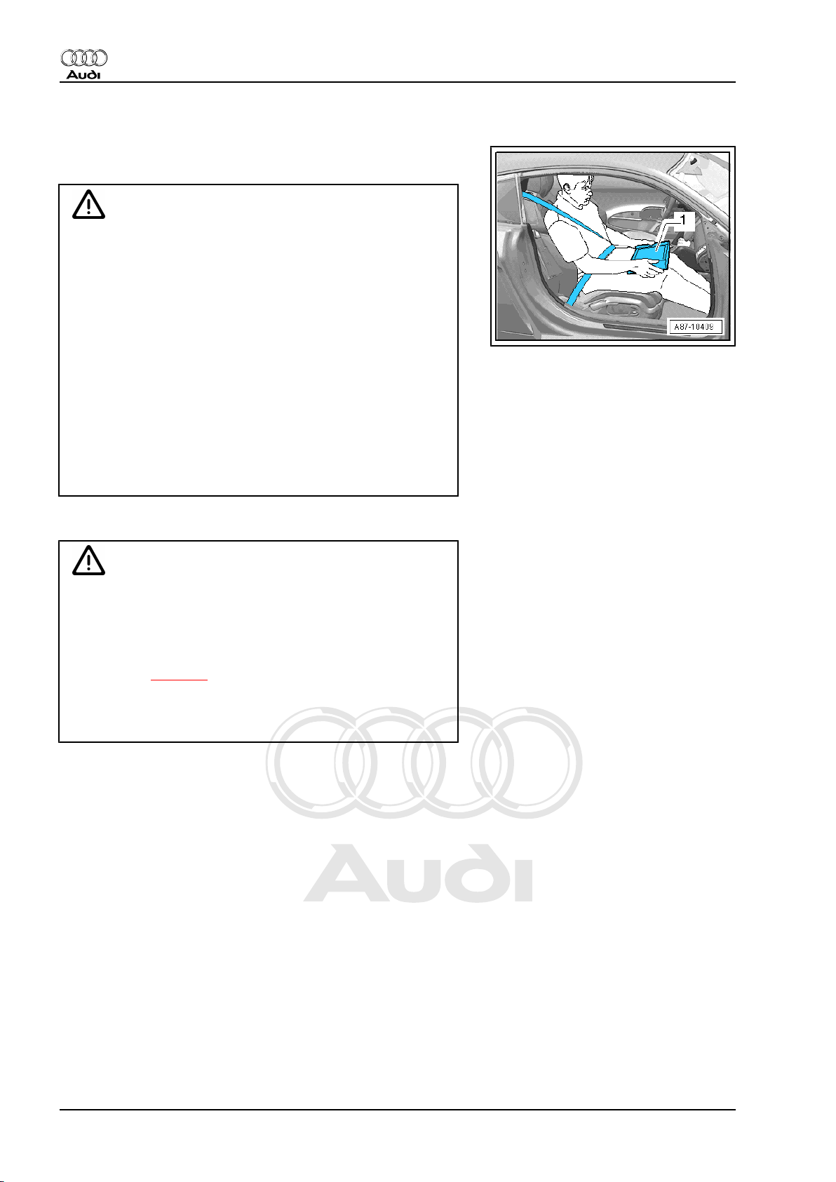
WARNING
Accidents can be caused if the driver is distracted by test
equipment while road-testing, or if test equipment is not prop‐
erly secured.
Persons sitting in the front passenger's seat could be injured if
the airbag is triggered in an accident.
• The use of test equipment while driving causes distraction.
• There is an increased risk of injury if test equipment is not
secured.
♦ Move the passenger's seat back as far as it will go.
♦ Use only vehicle diagnosis and service information sys‐
tem -VAS 5052 A- or diagnosis system -VAS 5053- .
♦ The test equipment -1- must rest flat on the passenger's
thighs (as shown in illustration) and must be operated by
the passenger.
When working on the fuel system note the following warnings:
WARNING
The fuel system operates at extremely high pressure. This can
cause injury.
♦ The fuel system is pressurised. The fuel pressure in the
high-pressure section of the injection system must be re‐
duced to a residual pressure prior to opening; for proce‐
dure see ⇒ page 4 .
♦ The connection must be opened immediately after reduc‐
ing the pressure; wrap a cloth around the connection and
allow the residual pressure (approx. 7 bar) to dissipate.
To prevent injuries to persons and/or damage to the fuel injection
and ignition system, the following must be noted:
2 Rep. Gr.24 - Mixture preparation - injection
Page 7
Protected by copyright. Copying for private or commercial purposes, in part or in whole, is not
permitted unless authorised by AUDI AG. AUDI AG does not guarantee or accept any liability
with respect to the correctness of information in this document. Copyright by AUDI AG.
Direct petrol injection and ignition system (5-cyl. 2.5 ltr. 4-valve turbo) - Edition 03.2009
♦ Persons wearing a cardiac pacemaker must at all times main‐
tain a safe distance from high-voltage components such as the
ignition system and gas-discharge headlights.
♦ Do not open any fuel line connections while the engine is run‐
ning.
♦ Always switch off the ignition before connecting or discon‐
necting injection or ignition system wiring or tester cables.
♦ Certain tests may lead to a fault being detected by the control
unit and stored. The fault memory should therefore be inter‐
rogated and (if necessary) erased after completing the tests
and any repair work that may be required.
♦ If the fault memory has been erased, you must generate the
readiness code again.
♦ Always switch off the ignition before cleaning the engine.
♦ Always switch off the ignition before connecting or discon‐
necting the battery, otherwise the engine control unit may be
damaged.
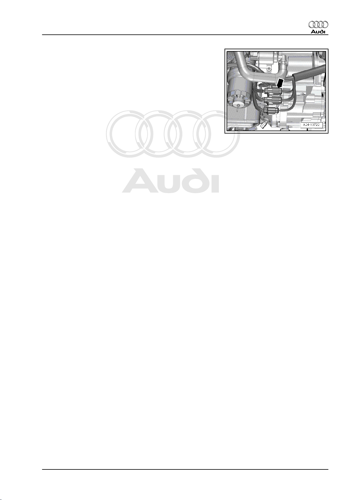
♦ If you want to crank the engine at starting speed without ac‐
tually starting it (e.g. compression test), first unplug the con‐
nectors from the ignition coils.
♦ Additionally unplug electrical connector -arrow- for injectors.
– Then connect vehicle diagnostic, testing and information sys‐
tem -VAS 5051B- and generate readiness code in engine
control unit using “Guided Fault Finding” mode.
Audi TT 2007 ➤
1.3 Rules for cleanliness when working on fuel supply system and injection system
Even small amounts of dirt can cause malfunctions. For this rea‐
son, please observe the following rules when working on the fuel
supply system and injection system:
♦ Carefully clean connection points and the surrounding area
with engine cleaner or brake cleaner and dry thoroughly before
opening.
♦ Seal off open pipes/lines and connections immediately with
clean plugs, e.g. from engine bung set -VAS 6122- .
♦ Place parts that have been removed on a clean surface and
cover them over. Use only lint-free cloths.
♦ Carefully cover or seal open components if repairs cannot be
carried out immediately.
♦ Only install clean components; replacement parts should only
be unpacked immediately prior to installation. Do not use parts
that have been previously unpacked and stored away loose
(e.g. in toolboxes, etc.).
♦ When the system is open: Do not work with compressed air.
Do not move the vehicle unless absolutely necessary.
♦ Protect unplugged electrical connectors against dirt and mois‐
ture and make sure connections are dry when attaching.
1. Safety precautions and rules for cleanliness 3
Page 8
Protected by copyright. Copying for private or commercial purposes, in part or in whole, is not
permitted unless authorised by AUDI AG. AUDI AG does not guarantee or accept any liability
with respect to the correctness of information in this document. Copyright by AUDI AG.
Audi TT 2007 ➤
Direct petrol injection and ignition system (5-cyl. 2.5 ltr. 4-valve turbo) - Edition 03.2009
1.4 Important: Required procedure prior to opening high-pressure injection system
WARNING
The fuel system operates at extremely high pressure. This can
cause injury.
♦ The injection system consists of a high-pressure section
(maximum approx. 125 bar) and a low-pressure section
(approx. 7 bar).
♦ Prior to opening the high-pressure section (e.g. when re‐
moving the high-pressure pump, fuel rail, injectors, fuel
pipes or fuel pressure sender -G247- ), the fuel pressure
in the high-pressure section must be reduced to a residual
pressure of approx. 7 bar. The procedure is described be‐
low.
Reducing fuel pressure in high-pressure section
– Connect up the vehicle diagnostic, testing and information
system -VAS 5051B- .
– Start engine and run at idling speed.
– Select “Engine electronics” in vehicle self-diagnosis.
– Then select function read “Measured values”.
– Select measured value block 140.
– With engine idling the fuel pressure is displayed in zone 3.
– With engine idling, pull out fuse for fuel pump control unit -
J538- ⇒ Current flow diagrams, Electrical fault finding and
Fitting locations.
Note
Removing the fuse will interrupt the voltage supply “terminal 30”
for the fuel pump control unit -J538- .
– Observe fuel pressure displayed on diagnostic system.
• The fuel pressure will decrease very quickly because the me‐
chanical high-pressure pump is no longer being supplied with
fuel from the fuel tank by the fuel pump -G23- .
– Switch off ignition as soon as fuel pressure has dropped to
approx. 8 bar.
Note
Fuel pressure must not fall below 6 bar, otherwise the engine will
stall (this could damage the catalytic converter).
4 Rep. Gr.24 - Mixture preparation - injection
Page 9
Protected by copyright. Copying for private or commercial purposes, in part or in whole, is not
permitted unless authorised by AUDI AG. AUDI AG does not guarantee or accept any liability
with respect to the correctness of information in this document. Copyright by AUDI AG.
Direct petrol injection and ignition system (5-cyl. 2.5 ltr. 4-valve turbo) - Edition 03.2009
WARNING
There is a risk of injury: avoid skin contact with fuel.
♦ The fuel lines are still filled with fuel, however the fuel is
no longer under high pressure. Wear safety goggles and
protective clothing when opening the fuel system.
♦ Before opening the high-pressure section, wrap a cloth
around the connection.
– The high-pressure system must be opened “immediately” after
reducing the fuel pressure; wrap a clean cloth around the con‐
nection. Catch the escaping fuel.
The following operations must be performed after completing re‐
pair work:
– Refit fuse.
– Then connect vehicle diagnostic, testing and information sys‐
tem -VAS 5051B- and generate readiness code in engine
control unit using “Guided Fault Finding” mode.
Audi TT 2007 ➤
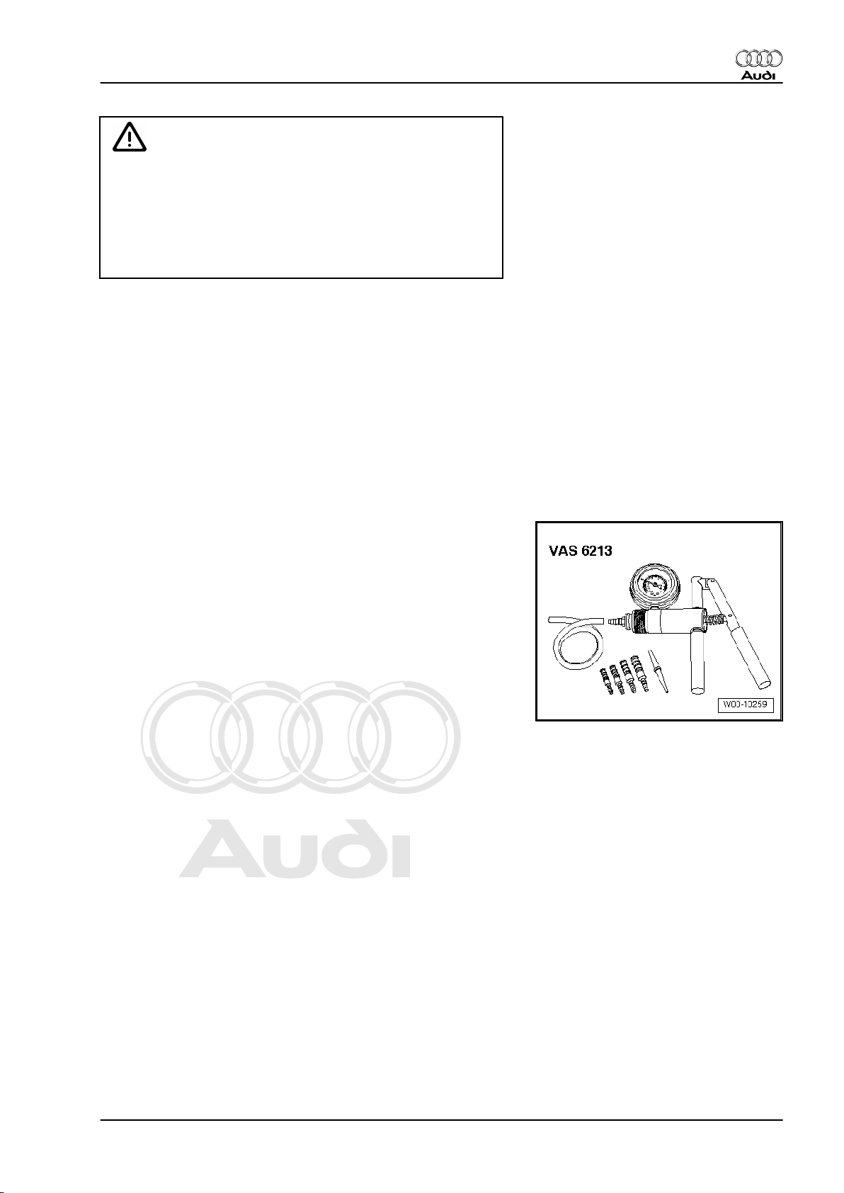
1.5 Checking vacuum system
Special tools and workshop equipment required
♦ Hand vacuum pump -VAS 6213-
Procedure
– Check all vacuum lines in the complete vacuum system for:
♦ Cracks
♦ Traces of animal bites
♦ Kinked or crushed lines
♦ Lines porous or leaking
– Check vacuum line to solenoid valve and from solenoid valve
to corresponding component.
– If a fault is stored in the fault memory, check the vacuum lines
leading to the corresponding component and also check the
other vacuum lines leading to other components.
– If it is not possible to build up pressure with the hand vacuum
pump -VAS 6213- or if the pressure drops again immediately,
check the hand vacuum pump and connecting hoses for leaks.
1. Safety precautions and rules for cleanliness 5
Page 10
Protected by copyright. Copying for private or commercial purposes, in part or in whole, is not
permitted unless authorised by AUDI AG. AUDI AG does not guarantee or accept any liability
with respect to the correctness of information in this document. Copyright by AUDI AG.
Audi TT 2007 ➤
Direct petrol injection and ignition system (5-cyl. 2.5 ltr. 4-valve turbo) - Edition 03.2009
2 Injection system
2.1 Technical data
Engine data 2.5 ltr. / 4V / 250 kW engine
Idling speed is not adjustable (con‐
trolled by idling speed stabilisation).
Maximum rpm governed by deacti‐
vation of fuel injectors
Fuel pressure Initial fuel pressure up to high-pres‐
sure pump (generated by electric
fuel pump in fuel tank)
Pressure in high-pressure fuel cir‐
cuit (generated by mechanical sin‐
gle-plunger pump) at a coolant
temperature of approx. 85°C.
680 ... 920 rpm
6900 rpm
7 bar
17.5 ... 125 bar (depending on op‐
erating conditions)
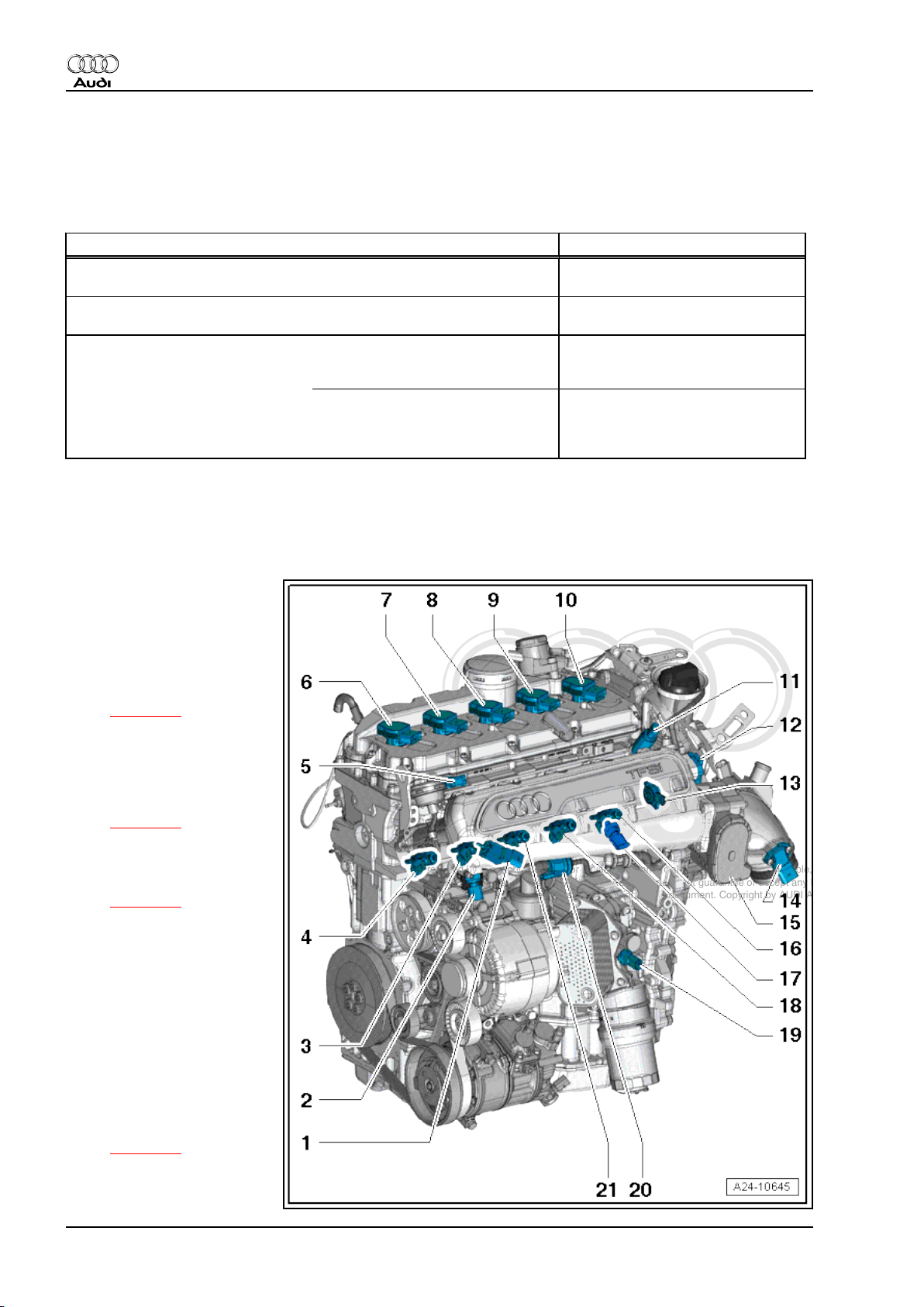
2.2 Fitting locations - overview
Part 1
1 - Intake manifold flap valve N316-
2 - Fuel pressure sender for
low pressure -G410-
3 - Injector, cylinder 2 -N31-
❑ Removing and installing
⇒ page 26
4 - Injector, cylinder 1 -N30-
5 - Hall sender -G40-
❑ Inlet side
❑ Removing and installing
⇒ page 56
6 - Ignition coil 1 with output
stage -N70-
❑ Removing and installing
⇒ page 54
7 - Ignition coil 2 with output
stage -N127-
8 - Ignition coil 3 with output
stage -N291-
9 - Ignition coil 4 with output
stage -N292-
10 - Ignition coil 5 with output
stage -N323-
11 - Camshaft control valve 1 N205-
❑ Fitting location
⇒ page 11
❑ Removing and installing
⇒ Rep. Gr. 15
6 Rep. Gr.24 - Mixture preparation - injection
Page 11

Protected by copyright. Copying for private or commercial purposes, in part or in whole, is not
permitted unless authorised by AUDI AG. AUDI AG does not guarantee or accept any liability
with respect to the correctness of information in this document. Copyright by AUDI AG.
Audi TT 2007 ➤
Direct petrol injection and ignition system (5-cyl. 2.5 ltr. 4-valve turbo) - Edition 03.2009
12 - Intake air temperature sender -G42- / intake manifold pressure sender -G71-
❑ Removing and installing ⇒ page 17
13 - Intake manifold flap potentiometer -G336-
❑ After renewing, perform “Adaption” in “Guided Functions” under “Adapting potentiometer for air flow
control flaps”
14 - Charge air pressure sender -G31- / intake air temperature sender 2 -G299-
❑ Removing and installing ⇒ Rep. Gr. 21
15 - Throttle valve module -J338-
❑ Including throttle valve drive for electric throttle -G186- , throttle valve drive angle sender 1 for electric
throttle -G187- and throttle valve drive angle sender 2 for electric throttle -G188❑ Removing and installing ⇒ page 18
❑ After renewing, perform “Adaption” in “Guided Functions”
16 - Injector, cylinder 5 -N83-
17 - Fuel pressure sender -G247-
❑ Removing and installing ⇒ page 30
18 - Injector, cylinder 4 -N33-
19 - Oil pressure switch -F22-
❑ Removing and installing ⇒ Rep. Gr. 17
20 - Activated charcoal filter solenoid valve 1 -N80-
21 - Injector, cylinder 3 -N32-
Part 2
2. Injection system 7
Page 12
Protected by copyright. Copying for private or commercial purposes, in part or in whole, is not
permitted unless authorised by AUDI AG. AUDI AG does not guarantee or accept any liability
with respect to the correctness of information in this document. Copyright by AUDI AG.
Audi TT 2007 ➤
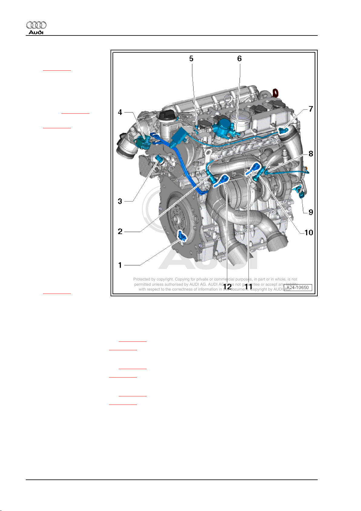
Direct petrol injection and ignition system (5-cyl. 2.5 ltr. 4-valve turbo) - Edition 03.2009
1 - Engine speed sender -G28-
❑ Removing and installing
⇒ page 57
2 - Lambda probe after catalyt‐
ic converter -G130- with Lamb‐
da probe 1 heater after catalyt‐
ic converter -Z29-
❑ Fitting location of con‐
nector ⇒ page 10
❑ Removing and installing
⇒ page 42
3 - Coolant temperature send‐
er -G62-
❑ Removing and installing
⇒ Rep. Gr. 19
4 - Turbocharger air recircula‐
tion valve -N249-
❑ Removing and installing
⇒ Rep. Gr. 21
5 - Exhaust camshaft control
valve 1 -N318-
❑ Removing and installing
⇒ Rep. Gr. 15
6 - Fuel metering valve -N290-
❑ Combined with high-
pressure pump
❑ Cannot be renewed
separately
7 - Hall sender 3 -G300-
❑ Exhaust side
❑ Removing and installing
⇒ page 56
8 - Exhaust gas temperature sender 1 -G235-
❑ Removing and installing ⇒ Rep. Gr. 26
9 - Charge pressure control solenoid valve -N75-
10 - Lambda probe before catalytic converter -G39- with Lambda probe heater -Z19-
❑ Fitting location of connector ⇒ page 10
❑ Removing and installing ⇒ page 40
11 - Knock sensor 1 -G61-
❑ Fitting location of connector ⇒ page 10
❑ Removing and installing ⇒ page 55
12 - Knock sensor 2 -G66-
❑ Fitting location of connector ⇒ page 10
❑ Removing and installing ⇒ page 55
8 Rep. Gr.24 - Mixture preparation - injection
Page 13
Protected by copyright. Copying for private or commercial purposes, in part or in whole, is not
permitted unless authorised by AUDI AG. AUDI AG does not guarantee or accept any liability
with respect to the correctness of information in this document. Copyright by AUDI AG.
Direct petrol injection and ignition system (5-cyl. 2.5 ltr. 4-valve turbo) - Edition 03.2009
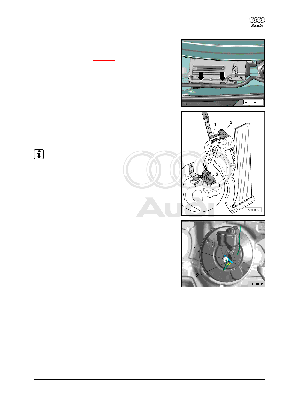
Fitting location of engine control unit -J623-
♦ In electronics box (plenum chamber)
♦ Removing and installing ⇒ page 47
Fitting location of accelerator position sender -G79- with acceler‐
ator position sender 2 -G185-
♦ Combined with accelerator pedal module
♦ Removing and installing accelerator pedal module ⇒ Rep. Gr.
20
Note
Audi TT 2007 ➤
The illustration shows the set-up for left-hand drive vehicles.
Fitting location of brake light switch -F- with brake pedal switch F47-
1 - Brake light switch -F- with brake pedal switch -F47-
♦ On brake master cylinder
♦ Removing and installing ⇒ Rep. Gr. 47
2. Injection system 9
Page 14
Protected by copyright. Copying for private or commercial purposes, in part or in whole, is not
permitted unless authorised by AUDI AG. AUDI AG does not guarantee or accept any liability
with respect to the correctness of information in this document. Copyright by AUDI AG.
Audi TT 2007 ➤
Direct petrol injection and ignition system (5-cyl. 2.5 ltr. 4-valve turbo) - Edition 03.2009
Fitting location of clutch position sender -G476-
♦ On clutch master cylinder-arrow-.
♦ Removing and installing ⇒ Rep. Gr. 30
Fitting location of electrical connectors for Lambda probes
1 - For Lambda probe, before catalytic converter -G39- with
Lambda probe heater -Z19-
2 - For Lambda probe after catalytic converter -G130- with
Lambda probe 1 heater after catalytic converter -Z29-
♦ At plenum chamber partition panel
Fitting location of electrical connectors for knock sensors
1 - For knock sensor 2 -G66-
2 - For knock sensor 1 -G61-
♦ On cylinder head cover
Fitting location of electrical connectors on cylinder head
1 - For engine speed sender -G28-
3 - For injectors
10 Rep. Gr.24 - Mixture preparation - injection
Page 15
Protected by copyright. Copying for private or commercial purposes, in part or in whole, is not
permitted unless authorised by AUDI AG. AUDI AG does not guarantee or accept any liability
with respect to the correctness of information in this document. Copyright by AUDI AG.
Direct petrol injection and ignition system (5-cyl. 2.5 ltr. 4-valve turbo) - Edition 03.2009
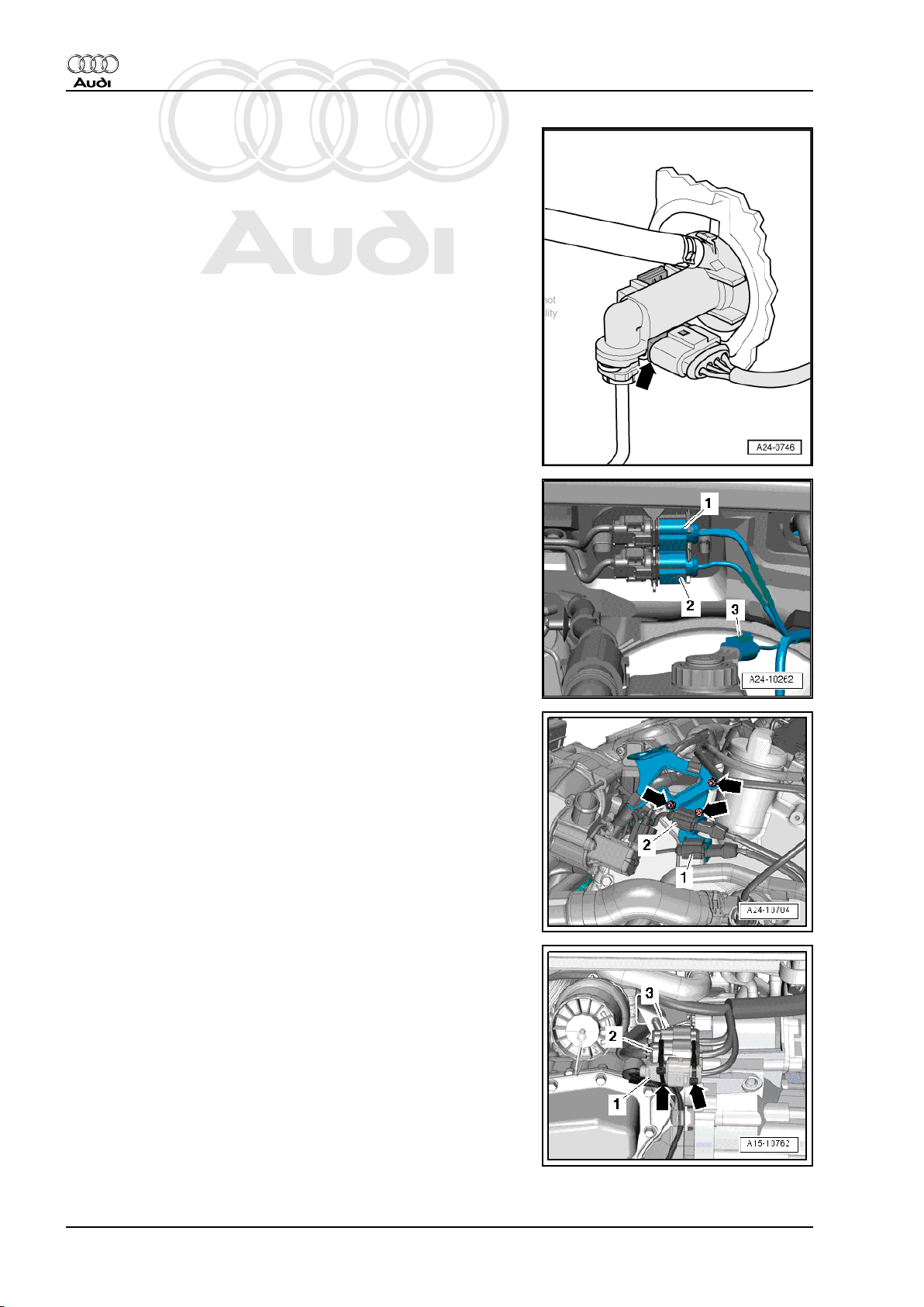
Fitting location of fuel pump control unit -J538-
2 - Fuel pump control unit -J538-
3 - Bracket
♦ On underside in front of fuel tank
Camshaft control valve 1 -N205-
Audi TT 2007 ➤
Fitting location of continued coolant circulation pump -V51-
2 - Continued coolant circulation pump -V51-
♦ On cylinder block (inlet side)
Fitting location of solenoid for coolant circuit -N492-
1 - Solenoid for coolant circuit -N492-
♦ On cylinder block (inlet side)
2. Injection system 11
Page 16
Protected by copyright. Copying for private or commercial purposes, in part or in whole, is not
permitted unless authorised by AUDI AG. AUDI AG does not guarantee or accept any liability
with respect to the correctness of information in this document. Copyright by AUDI AG.
Audi TT 2007 ➤
Direct petrol injection and ignition system (5-cyl. 2.5 ltr. 4-valve turbo) - Edition 03.2009
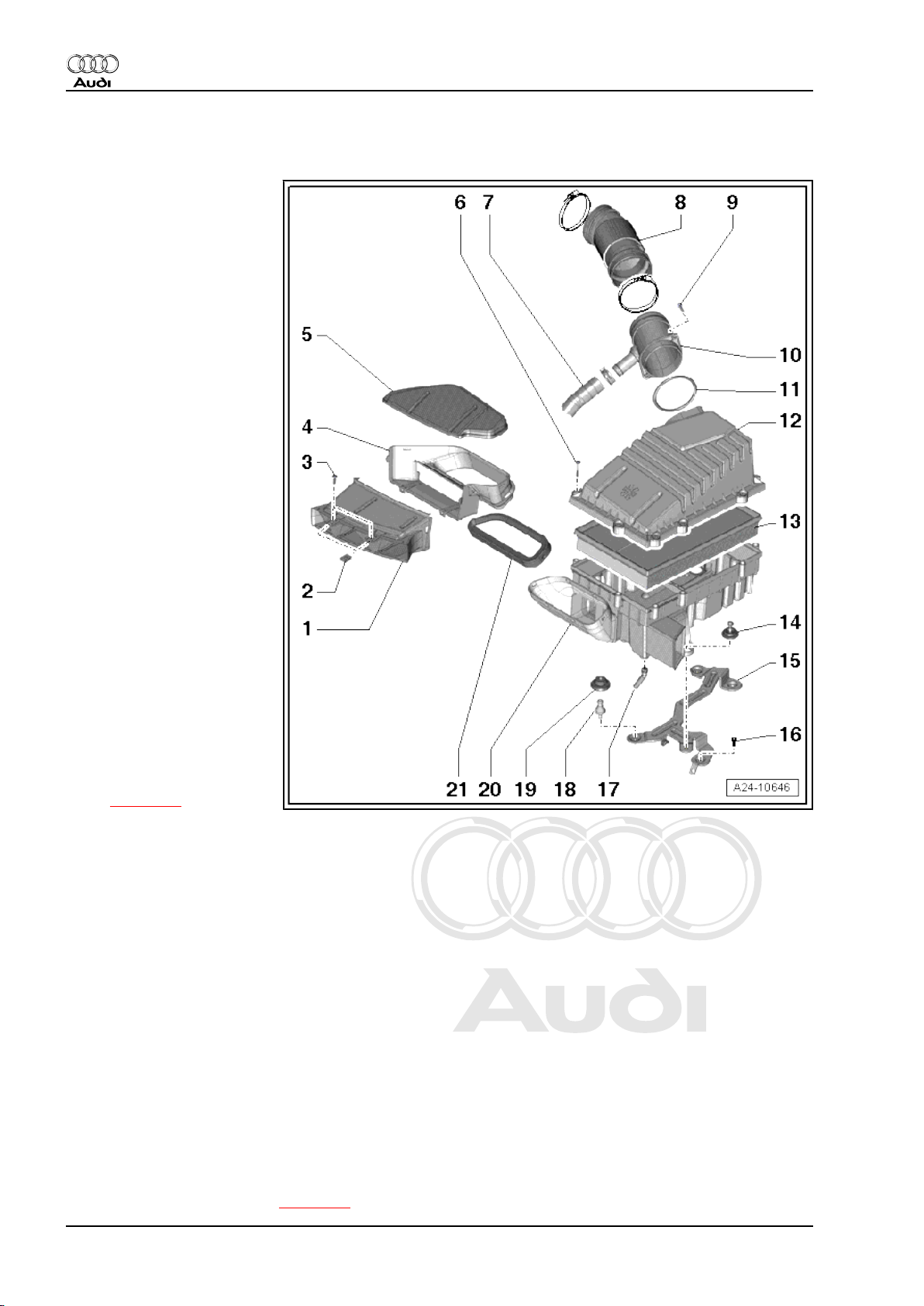
2.3 Air cleaner - exploded view
1 - Front air duct
❑ Clean out dirt, leaves
and salt deposits
2 - Clip nut
3 - Bolt
❑ 1.5 Nm
4 - Lower part of air duct
❑ Clean out dirt, leaves
and salt deposits
5 - Air duct cover
6 - Bolt
❑ 5 Nm
7 - Hose
❑ For crankcase breather
8 - Air hose
9 - Bolt
❑ 3 Nm
10 - Air pipe
11 - Seal
❑ Renew if damaged
12 - Air cleaner (top section)
❑ Clean out salt deposits,
dirt and leaves, etc.
13 - Air filter element
❑ Always use genuine
part for air filter element
❑ Removing and installing
⇒ page 13
❑ Observe change intervals ⇒ Maintenance ; Booklet 810
14 - Bolt
❑ With captive rubber grommet
❑ 10 Nm
15 - Bracket
❑ For air cleaner housing
16 - Bolt
❑ With captive rubber grommet
❑ 10 Nm
17 - Water drain
❑ Clean
18 - Retaining peg
❑ 10 Nm
19 - Rubber grommet
20 - Air cleaner (bottom section)
❑ Clean out salt deposits, dirt and leaves, etc.
❑ Removing and installing ⇒ page 15
12 Rep. Gr.24 - Mixture preparation - injection
Page 17
Protected by copyright. Copying for private or commercial purposes, in part or in whole, is not
permitted unless authorised by AUDI AG. AUDI AG does not guarantee or accept any liability
with respect to the correctness of information in this document. Copyright by AUDI AG.
Direct petrol injection and ignition system (5-cyl. 2.5 ltr. 4-valve turbo) - Edition 03.2009
21 - Seal
❑ Clipped into air cleaner (bottom section)
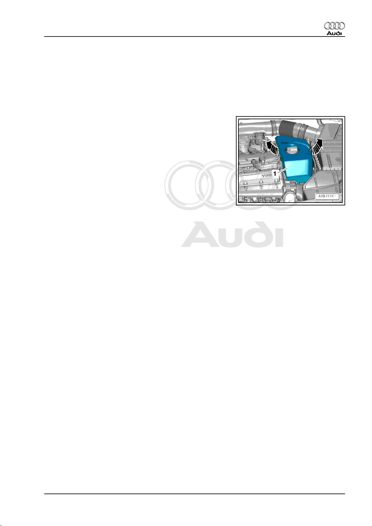
2.4 Removing and installing air filter ele‐
ment
Removing
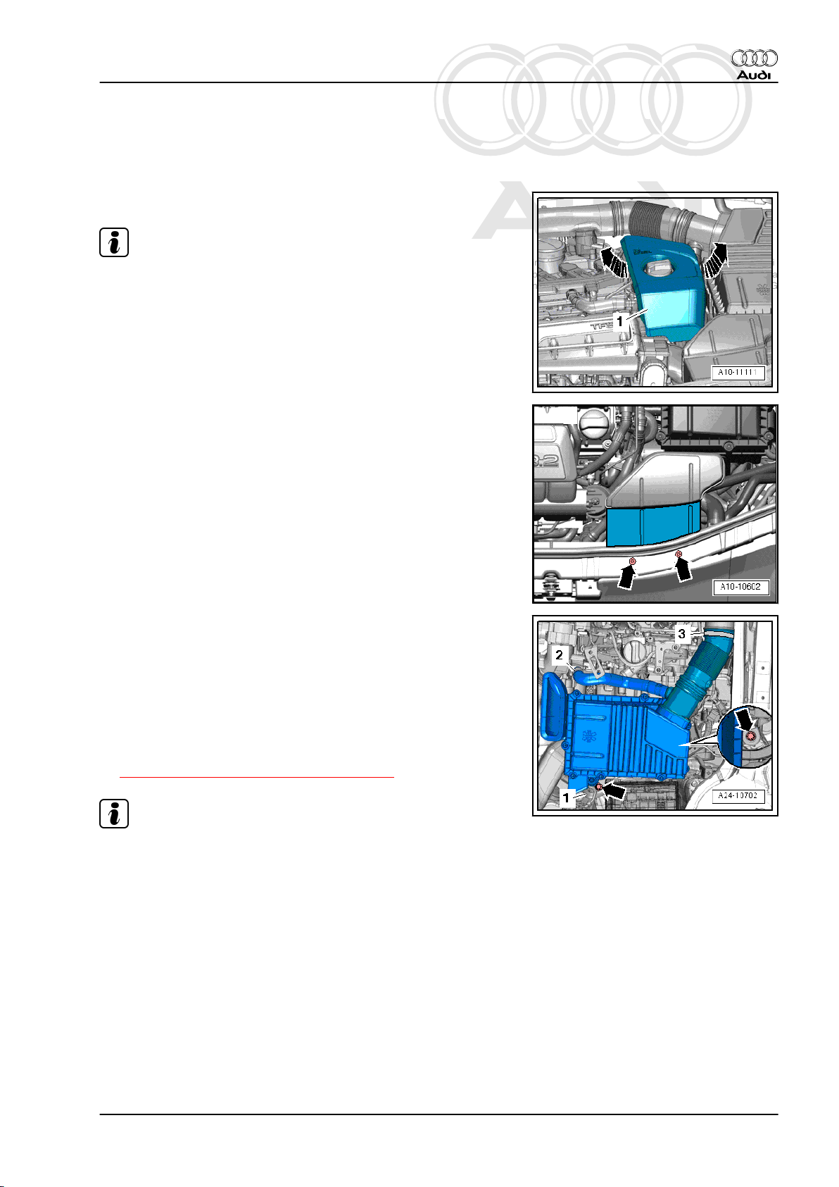
– Lift off engine cover panel -1- -arrows-.
Audi TT 2007 ➤
2. Injection system 13
Page 18
Protected by copyright. Copying for private or commercial purposes, in part or in whole, is not
permitted unless authorised by AUDI AG. AUDI AG does not guarantee or accept any liability
with respect to the correctness of information in this document. Copyright by AUDI AG.
Audi TT 2007 ➤
Direct petrol injection and ignition system (5-cyl. 2.5 ltr. 4-valve turbo) - Edition 03.2009
– Remove all bolts from air cleaner (top section) -arrow- and
swivel air cleaner (top section) away upwards.
– Take out air filter element.
Installing
Installation is carried out in the reverse order; note the following:
• Tightening torques
⇒ “2.3 Air cleaner - exploded view”, page 12
Note
♦
Always use genuine part for air filter element.
♦
The inside of the air cleaner housing must be clean.
♦
To prevent malfunctions, cover the air pipes etc. with clean
cloths when blowing out the air cleaner housing with com‐
pressed air.
♦
Hose connections and air pipes and hoses must be free of oil
and grease before assembly.
♦
Do not use any lubricants containing silicone when assem‐
bling.
♦
Secure all hose connections with the correct type of hose clips
(same as original equipment) ⇒ Electronic parts catalogue .
♦
To ensure that the air hoses can be properly secured at their
connections, spray rust remover onto the worm thread of used
hose clips before installing.
– Blow out water drain (small hole in bottom section of air clean‐
er housing) with compressed air.
– Clean salt residue, dirt and leaves out of air cleaner housing
(top and bottom sections), using a vacuum cleaner if neces‐
sary.
– Check for salt residue, dirt and leaves in air hoses (engine
intake side).
– Check for dirt and leaves in air duct going from lock carrier to
air cleaner housing.
– When fitting air filter element, check that it is properly centred
in the retainer in the air cleaner (bottom section).
– Carefully fit top section of air cleaner onto bottom section,
without using any force. When doing so, make sure that the
air cleaner (top section) is fitted straight on the air filter element
(note the position of the sealing lip on the air filter element).
14 Rep. Gr.24 - Mixture preparation - injection
Page 19
Protected by copyright. Copying for private or commercial purposes, in part or in whole, is not
permitted unless authorised by AUDI AG. AUDI AG does not guarantee or accept any liability
with respect to the correctness of information in this document. Copyright by AUDI AG.
Direct petrol injection and ignition system (5-cyl. 2.5 ltr. 4-valve turbo) - Edition 03.2009
2.5 Removing and installing air cleaner housing
Removing
– Lift off engine cover panel -1- -arrows-.
Note
Fit all cable ties in the original positions when installing.
– Unscrew bolts -arrows- and remove air duct.
Audi TT 2007 ➤
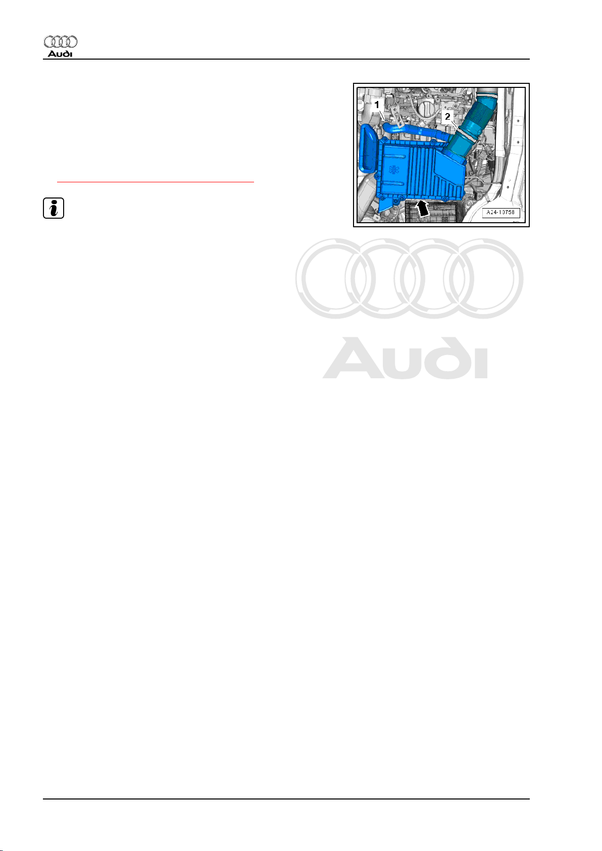
– Release hose clips -2- and -3- and disconnect air hoses.
– Move clear electrical wiring harness -1- at bracket for air clean‐
er housing.
– Unscrew bolts -arrows- and detach air cleaner housing.
Installing
Installation is carried out in the reverse order; note the following:
• Tightening torques
⇒ “2.3 Air cleaner - exploded view”, page 12
Note
♦
Hose connections and air pipes and hoses must be free of oil
and grease before assembly.
♦
Do not use any lubricants containing silicone when assem‐
bling.
♦
Secure all hose connections with the correct type of hose clips
(same as original equipment) ⇒ Electronic parts catalogue .
♦
To ensure that the air hoses can be properly secured at their
connections, spray rust remover onto the worm thread of used
hose clips before installing.
– Check for dirt and leaves in air duct going from lock carrier to
air cleaner housing.
2. Injection system 15
Page 20

Protected by copyright. Copying for private or commercial purposes, in part or in whole, is not
permitted unless authorised by AUDI AG. AUDI AG does not guarantee or accept any liability
with respect to the correctness of information in this document. Copyright by AUDI AG.
Audi TT 2007 ➤
Direct petrol injection and ignition system (5-cyl. 2.5 ltr. 4-valve turbo) - Edition 03.2009
2.6 Intake manifold (top section) - exploded view
1 - Seal
❑ Renew
2 - Throttle valve module J338-
❑ Removing and installing
⇒ page 18
❑ After renewing, perform
“Adaption” in “Guided
Functions”
3 - Non-return valve
4 - Bolt
❑ 9 Nm
5 - Activated charcoal filter sol‐
enoid valve 1 -N80-
6 - Bracket
7 - Bolt
❑ 9 Nm
8 - Intake manifold (top sec‐
tion)
❑ Removing and installing
⇒ page 20
9 - Bolt
❑ Tightening torque and
sequence ⇒ page 17
10 - Gasket
❑ Renew
11 - Hose
❑ For crankcase breather
12 - O-ring
❑ Renew
13 - O-ring
❑ Renew
14 - Intake air temperature sender -G42- / intake manifold pressure sender -G71-
❑ Removing and installing ⇒ page 17
15 - Bolt
❑ 9 Nm
16 - Gasket
❑ Renew
17 - Union
❑ Apply locking fluid when installing; refer to ⇒ Electronic parts catalogue
❑ 20 Nm
18 - Intake connecting pipe
19 - Bolt
❑ 9 Nm
16 Rep. Gr.24 - Mixture preparation - injection
Page 21

Protected by copyright. Copying for private or commercial purposes, in part or in whole, is not
permitted unless authorised by AUDI AG. AUDI AG does not guarantee or accept any liability
with respect to the correctness of information in this document. Copyright by AUDI AG.
Direct petrol injection and ignition system (5-cyl. 2.5 ltr. 4-valve turbo) - Edition 03.2009
20 - O-ring
❑ Renew
21 - Turbocharger air recirculation valve -N249-
❑ Removing and installing ⇒ Rep. Gr. 21
22 - Bolt
❑ 9 Nm
23 - O-ring
❑ Renew
24 - Charge air pressure sender -G31- / intake air temperature sender 2 -G299-
❑ Removing and installing ⇒ Rep. Gr. 21
25 - Bolt
❑ 9 Nm
Intake manifold (top section) - tightening torque and sequence
– Tighten bolts for intake manifold in the sequence -1 to 5-.
♦ Initially screw in bolts by hand until they make contact.
♦ Subsequently tighten to 9 Nm
Audi TT 2007 ➤
2.7 Removing and installing intake air tem‐
perature sender -G42- / intake manifold
pressure sender -G71-
Removing
– Lift off engine cover panel -1- -arrows-.
2. Injection system 17
Page 22

Protected by copyright. Copying for private or commercial purposes, in part or in whole, is not
permitted unless authorised by AUDI AG. AUDI AG does not guarantee or accept any liability
with respect to the correctness of information in this document. Copyright by AUDI AG.
Audi TT 2007 ➤
Direct petrol injection and ignition system (5-cyl. 2.5 ltr. 4-valve turbo) - Edition 03.2009
– Unplug electrical connector -1-.
– Unscrew bolts -2- and detach intake air temperature sender -
G42- / intake manifold pressure sender -G71- .
Installing
Installation is carried out in the reverse order; note the following:
• Tightening torques
⇒ “2.6 Intake manifold (top section) - exploded view”,
page 16
Note
Fit new O-ring.
2.8 Removing and installing throttle valve
module -J338-
Removing
– Unscrew bolts -arrows- and remove air duct.
– Release hose clip -arrow- and detach air hose.
– Loosen hose clip -2-.
– Unplug electrical connector -3- at charge air pressure sender
-G31- / intake air temperature sender 2 -G299- .
Note
Disregard -item 1-.
18 Rep. Gr.24 - Mixture preparation - injection
Page 23

Protected by copyright. Copying for private or commercial purposes, in part or in whole, is not
permitted unless authorised by AUDI AG. AUDI AG does not guarantee or accept any liability
with respect to the correctness of information in this document. Copyright by AUDI AG.
Direct petrol injection and ignition system (5-cyl. 2.5 ltr. 4-valve turbo) - Edition 03.2009
– Unplug electrical connectors:
1 - Throttle valve module -J338-
3 - Turbocharger air recirculation valve -N249-
Note
Disregard -item 2-.
– Disengage activated charcoal filter solenoid valve 1 -N80-
-item 1-.
– Remove bolt -2-.
– Release hose clip -3- and detach hose.
Audi TT 2007 ➤
– Remove bolts -arrows- and detach throttle valve module -
J338- -item 1- with connection from air hose -2-.
Installing
Installation is carried out in the reverse order; note the following:
• Tightening torques
⇒ “2.6 Intake manifold (top section) - exploded view”,
page 16 and ⇒ “2.3 Air cleaner - exploded view”, page 12
Note
♦
Renew gasket and O-ring.
♦
Hose connections and air pipes and hoses must be free of oil
and grease before assembly.
♦
Do not use any lubricants containing silicone when assem‐
bling.
♦
Secure all hose connections with the correct type of hose clips
(same as original equipment) ⇒ Electronic parts catalogue .
♦
To ensure that the air hoses can be properly secured at their
connections, spray rust remover onto the worm thread of used
hose clips before installing.
– After renewing, perform “Adaption” in “Guided Functions” -
VAS 5051B- .
2. Injection system 19
Page 24

Protected by copyright. Copying for private or commercial purposes, in part or in whole, is not
permitted unless authorised by AUDI AG. AUDI AG does not guarantee or accept any liability
with respect to the correctness of information in this document. Copyright by AUDI AG.
Audi TT 2007 ➤
Direct petrol injection and ignition system (5-cyl. 2.5 ltr. 4-valve turbo) - Edition 03.2009
2.9 Removing and installing intake manifold (top section)
Removing
– Lift off engine cover panel -1- -arrows-.
– Unscrew bolts -arrows- and remove air duct.
– Release hose clip -arrow- and detach air hose.
– Loosen hose clip -2-.
– Unplug electrical connector -3- at charge air pressure sender
-G31- / intake air temperature sender 2 -G299- .
Note
Disregard -item 1-.
20 Rep. Gr.24 - Mixture preparation - injection
Page 25

Protected by copyright. Copying for private or commercial purposes, in part or in whole, is not
permitted unless authorised by AUDI AG. AUDI AG does not guarantee or accept any liability
with respect to the correctness of information in this document. Copyright by AUDI AG.
Direct petrol injection and ignition system (5-cyl. 2.5 ltr. 4-valve turbo) - Edition 03.2009
– Unplug electrical connectors:
1 - Throttle valve module -J338-
2 - Intake air temperature sender -G42- / intake manifold pres‐
sure sender -G71-
3 - Turbocharger air recirculation valve -N249-
– Disengage activated charcoal filter solenoid valve 1 -N80-
-item 1-.
– Remove bolt -2-.
– Release hose clip -3- and detach hose.
Audi TT 2007 ➤
2. Injection system 21
Page 26

Protected by copyright. Copying for private or commercial purposes, in part or in whole, is not
permitted unless authorised by AUDI AG. AUDI AG does not guarantee or accept any liability
with respect to the correctness of information in this document. Copyright by AUDI AG.
Audi TT 2007 ➤
Direct petrol injection and ignition system (5-cyl. 2.5 ltr. 4-valve turbo) - Edition 03.2009
– Press release tabs and disconnect crankcase breather hose
-arrow-.
– Unscrew bolts -1 ... 5- and detach intake manifold (top sec‐
tion).
Caution
Risk of damage to engine.
♦ Block off the openings of the intake ports in the cylinder
head with a clean cloth to prevent small items from drop‐
ping into the engine.
Installing
Installation is carried out in the reverse order; note the following:
• Tightening torques
⇒ “2.6 Intake manifold (top section) - exploded view”,
page 16 ,
⇒ Fig. “ Intake manifold (top section) - tightening torque and
sequence “ , page 17 and
⇒ “2.3 Air cleaner - exploded view”, page 12 .
Note
♦
Renew gasket and O-ring.
♦
Hose connections and air pipes and hoses must be free of oil
and grease before assembly.
♦
Do not use any lubricants containing silicone when assem‐
bling.
♦
Secure all hose connections with the correct type of hose clips
(same as original equipment) ⇒ Electronic parts catalogue .
♦
To ensure that the air hoses can be properly secured at their
connections, spray rust remover onto the worm thread of used
hose clips before installing.
22 Rep. Gr.24 - Mixture preparation - injection
Page 27

Protected by copyright. Copying for private or commercial purposes, in part or in whole, is not
permitted unless authorised by AUDI AG. AUDI AG does not guarantee or accept any liability
with respect to the correctness of information in this document. Copyright by AUDI AG.
Audi TT 2007 ➤
Direct petrol injection and ignition system (5-cyl. 2.5 ltr. 4-valve turbo) - Edition 03.2009
2.10 Intake manifold (bottom section), fuel rail and injectors - exploded view
1 - Bolt
❑ 9 Nm
2 - High-pressure pipe
WARNING
The fuel system oper‐
ates at extremely high
pressure. This can
cause injury.
♦The fuel pressure in the
high-pressure section of
the injection system must
be reduced to a residual
pressure prior to opening
the system.
❑ Reducing fuel pressure
in high-pressure section
of injection system
⇒ page 4
❑ Connections must not
be damaged
❑ Do not alter shape
❑ Removing and installing
⇒ page 37
❑ 27 Nm
3 - Threaded connection
❑ 40 Nm
4 - Fuel rail
❑ Removing and installing
⇒ page 24
5 - Bracket
6 - Bolt
❑ 9 Nm
7 - Bolt
❑ 9 Nm
8 - Intake manifold (bottom section)
❑ With vacuum unit for intake manifold flaps
❑ Removing and installing ⇒ page 24
9 - Locking pin
10 - Vacuum unit
11 - Bolt
❑ 9 Nm
12 - Gasket
❑ Renew
2. Injection system 23
Page 28

Protected by copyright. Copying for private or commercial purposes, in part or in whole, is not
permitted unless authorised by AUDI AG. AUDI AG does not guarantee or accept any liability
with respect to the correctness of information in this document. Copyright by AUDI AG.
Audi TT 2007 ➤
Direct petrol injection and ignition system (5-cyl. 2.5 ltr. 4-valve turbo) - Edition 03.2009
13 - Dowel pin
14 - Seal
15 - Washer
16 - Intake manifold flap potentiometer -G336-
❑ After renewing, perform “Adaption” in “Guided Functions” under “Adapting potentiometer for air flow
control flaps”
17 - Bolt
❑ 2.5 Nm
18 - Bolt
❑ 9 Nm
19 - Sealing element (top)
20 - Sealing element (bottom)
21 - Circlip
22 - Combustion chamber ring seal
❑ Do not apply grease to ring seal or use any other lubricants
❑ Renewing ⇒ “2.12 Removing and installing injectors”, page 26
23 - Injector
❑ Removing and installing ⇒ page 26
24 - Spacer ring
❑ Renew if damaged
25 - O-ring
❑ Renew
❑ Lubricate lightly with clean engine oil
26 - Support ring
❑ Renew
❑ Via this support ring, the fuel rail exerts the clamping force that holds the injector in the cylinder head
❑ Clipped to -item 23-
27 - Fuel pressure sender -G247-
❑ Removing and installing ⇒ page 30
❑ 25 Nm
Intake manifold (bottom section) - tightening torque and tightening
sequence
– Tighten bolts and nuts for intake manifold (bottom section) in
the sequence -1 to 11- in 2 stages.
♦ Tighten initially to 7 Nm
♦ Subsequently tighten to 9 Nm
2.11 Removing and installing intake manifold (bottom section) with fuel rail
Removing
– Remove intake manifold (top section) ⇒ page 20 .
24 Rep. Gr.24 - Mixture preparation - injection
Page 29

Protected by copyright. Copying for private or commercial purposes, in part or in whole, is not
permitted unless authorised by AUDI AG. AUDI AG does not guarantee or accept any liability
with respect to the correctness of information in this document. Copyright by AUDI AG.
Direct petrol injection and ignition system (5-cyl. 2.5 ltr. 4-valve turbo) - Edition 03.2009
– Remove high-pressure pipe ⇒ page 37 .
– Remove front noise insulation -1- ⇒ Rep. Gr. 66 .
Note
Fit all cable ties in the original positions when installing.
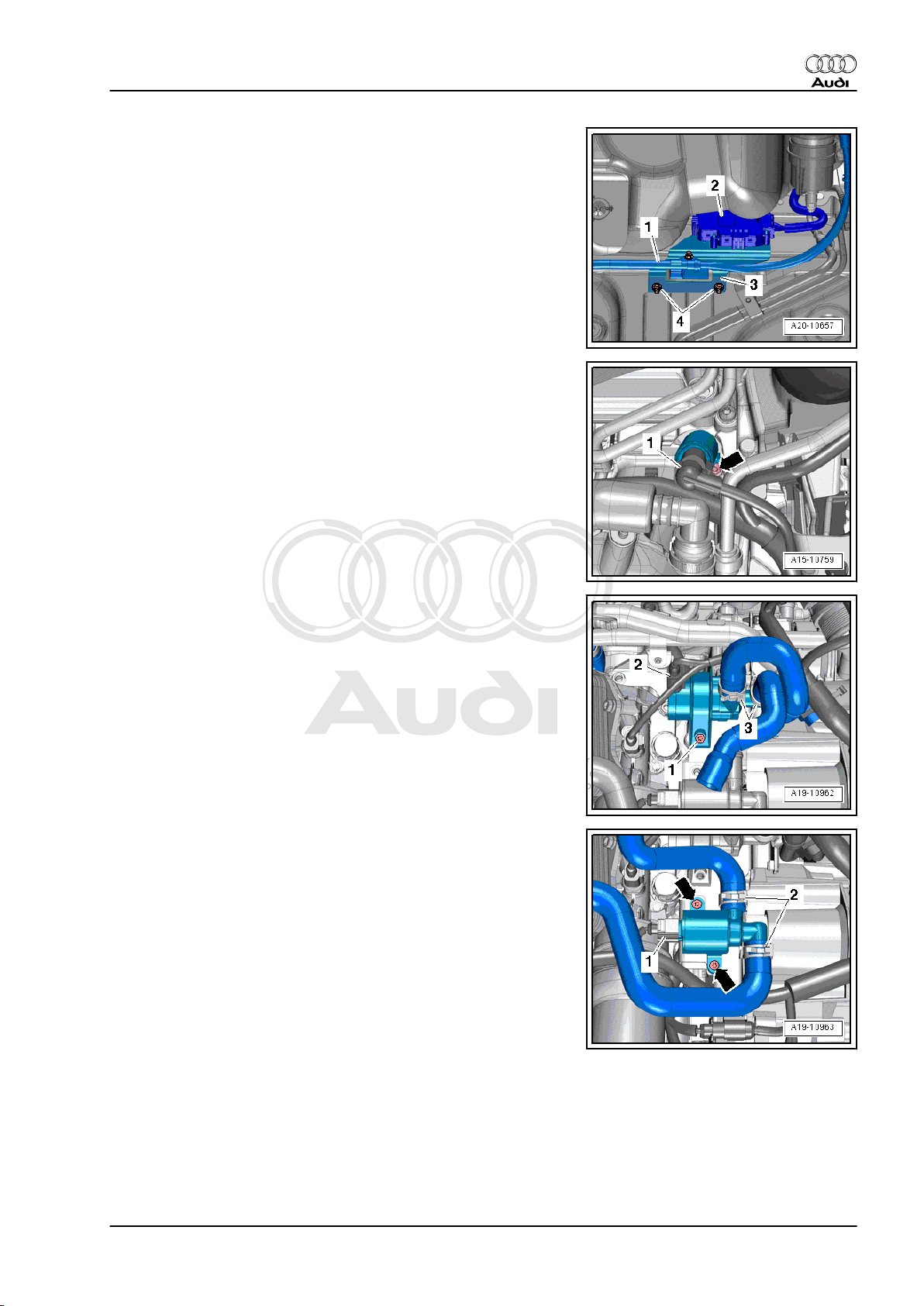
– Pull out oil dipstick -2-.
– Remove bolts -arrows- and lift off guide tube -1- for oil dipstick.
Audi TT 2007 ➤
– Unplug electrical connectors:
1 - Intake manifold flap valve -N316-
4 - Fuel pressure sender -G247-
5 - Intake manifold flap potentiometer -G336-
– Disconnect vacuum hose -2- and hose -3- from activated char‐
coal filter and move clear.
– Move electrical wiring clear.
2. Injection system 25
Page 30

Protected by copyright. Copying for private or commercial purposes, in part or in whole, is not
permitted unless authorised by AUDI AG. AUDI AG does not guarantee or accept any liability
with respect to the correctness of information in this document. Copyright by AUDI AG.
Audi TT 2007 ➤
Direct petrol injection and ignition system (5-cyl. 2.5 ltr. 4-valve turbo) - Edition 03.2009
– Loosen bolts in the sequence -11 ... 1-.
– Remove bolts and detach intake manifold (bottom section).
Caution
Risk of damage to engine.
♦ Block off the openings of the intake ports in the cylinder
head with a clean cloth to prevent small items from drop‐
ping into the engine.
Note
Injectors must be removed before gasket for intake manifold (bot‐
tom section) can be detached.
– Remove injectors ⇒ page 26 .
Installing
Installation is carried out in the reverse order; note the following:
• Tightening torque
⇒ Fig. “ Intake manifold (bottom section) - tightening torque
and tightening sequence “ , page 24 .
Note
♦
Renew gaskets and O-rings.
♦
Injectors must be installed after gasket for intake manifold
(bottom section) has been attached.
– Install injectors ⇒ page 26 .
– Secure dipstick guide tube ⇒ Rep. Gr. 17 .
– Install high-pressure pipe ⇒ page 37 .
– Install intake manifold (top section) ⇒ page 20 .
– Install noise insulation ⇒ Rep. Gr. 66 .
2.12 Removing and installing injectors
Special tools and workshop equipment required
♦ Tool set for FSI engines -T10133-
Removing
– Remove intake manifold (top section) ⇒ page 20 .
26 Rep. Gr.24 - Mixture preparation - injection
Page 31

Protected by copyright. Copying for private or commercial purposes, in part or in whole, is not
permitted unless authorised by AUDI AG. AUDI AG does not guarantee or accept any liability
with respect to the correctness of information in this document. Copyright by AUDI AG.
Direct petrol injection and ignition system (5-cyl. 2.5 ltr. 4-valve turbo) - Edition 03.2009
– Remove intake manifold (bottom section) ⇒ page 24 .
– Unplug electrical connectors -1 to 5- at injectors.
– Detach support ring -4- from injector -1-.
Audi TT 2007 ➤
– Apply puller -T10133/2A- to groove on injector.
– Attach removal tool -T10133/16- to puller.
– Pull out injector by screwing in bolt -1-.
– Repeat procedure for each injector.
– Detach gasket for intake manifold (bottom section).
2. Injection system 27
Page 32

Protected by copyright. Copying for private or commercial purposes, in part or in whole, is not
permitted unless authorised by AUDI AG. AUDI AG does not guarantee or accept any liability
with respect to the correctness of information in this document. Copyright by AUDI AG.
Audi TT 2007 ➤
Direct petrol injection and ignition system (5-cyl. 2.5 ltr. 4-valve turbo) - Edition 03.2009
Dismantling injector
– Pull O-ring -3- and spacer ring -2- off injector -1-.
– Detach circlip -7-, sealing element (top) -5- and sealing ele‐
ment (bottom) -6-.
– Carefully remove old combustion chamber ring seal -8-. To do
so, cut open seal using knife or prise open with small screw‐
driver and then pull off forwards.
Note
Take care not to damage groove on injector. The injector must be
renewed if the groove is damaged.
Installing
– Clean bore in cylinder head with nylon cylinder brush -
T10133/4- .
Note
♦
Renew combustion chamber ring seal and O-ring.
♦
Renew spacer ring if damaged.
– When re-installing an injector, clean any combustion residue
off groove for combustion chamber ring seal and injector stem
with a clean cloth.
– Fit assembly cone -T10133/5- with new combustion chamber
ring seal -1- onto injector -2-.
– Using assembly sleeve -T10133/6- , push combustion cham‐
ber ring seal onto assembly cone -T10133/5- as far as it will
go.
28 Rep. Gr.24 - Mixture preparation - injection
Page 33

Protected by copyright. Copying for private or commercial purposes, in part or in whole, is not
permitted unless authorised by AUDI AG. AUDI AG does not guarantee or accept any liability
with respect to the correctness of information in this document. Copyright by AUDI AG.
Direct petrol injection and ignition system (5-cyl. 2.5 ltr. 4-valve turbo) - Edition 03.2009
– Turn round assembly sleeve -T10133/6- and slide combustion
chamber ring seal into groove.
Note
The combustion chamber ring seal is widened when it is pushed
onto the injector. After pushing it on, it therefore has to be com‐
pressed again. This is done in two stages, as described below.
– Push calibration sleeve -T10133/7- onto injector as far as it will
go and simultaneously turn it slightly (approx. 180°).
– Pull calibration sleeve -T10133/7- off again by turning it in the
opposite direction.
Audi TT 2007 ➤
– Push calibration sleeve -T10133/8- onto injector as far as it will
go and simultaneously turn it slightly (approx. 180°).
– Pull calibration sleeve -T10133/8- off again by turning it in the
opposite direction.
– Before installing new injector -1-, lubricate new O-ring -3- light‐
ly with clean engine oil.
Note
The combustion chamber ring seal -8- must not be lubricated.
– Fit gasket for intake manifold (bottom section).
2. Injection system 29
Page 34

Protected by copyright. Copying for private or commercial purposes, in part or in whole, is not
permitted unless authorised by AUDI AG. AUDI AG does not guarantee or accept any liability
with respect to the correctness of information in this document. Copyright by AUDI AG.
Audi TT 2007 ➤
Direct petrol injection and ignition system (5-cyl. 2.5 ltr. 4-valve turbo) - Edition 03.2009
– Use assembly tool -T10133/9- to push injector as far as it will
go into hole in cylinder head.
Note
It should be possible to insert injector easily. If necessary wait
until the combustion chamber ring seal has contracted sufficient‐
ly.
– Check that injector is seated correctly in cylinder head:
• Electrical connector of injector must engage in recess in cyl‐
inder head.
– Install intake manifold (bottom section) ⇒ page 24 .
– Install intake manifold (top section) ⇒ page 20 .
2.13 Removing and installing fuel pressure sender -G247-
Removing
WARNING
The fuel system operates at extremely high pressure. This can
cause injury.
♦ The fuel pressure in the high-pressure section of the in‐
jection system must be reduced to a residual pressure
prior to opening the system.
– Reduce fuel pressure in high-pressure section of injection sys‐
tem ⇒ page 4 .
– Disengage activated charcoal filter solenoid valve 1 -N80-
-item 1-.
– Remove bolt -2-.
– Release hose clip -3- and detach hose.
Note
Place a cloth underneath to catch escaping fuel.
– Unplug electrical connector -arrow-.
– Unscrew fuel pressure sender -G247- .
Installing
Install in reverse order.
• Tightening torques
⇒ “2.10 Intake manifold (bottom section), fuel rail and injectors
- exploded view”, page 23 and
⇒ “2.3 Air cleaner - exploded view”, page 12
30 Rep. Gr.24 - Mixture preparation - injection
Page 35

Protected by copyright. Copying for private or commercial purposes, in part or in whole, is not
permitted unless authorised by AUDI AG. AUDI AG does not guarantee or accept any liability
with respect to the correctness of information in this document. Copyright by AUDI AG.
Audi TT 2007 ➤
Direct petrol injection and ignition system (5-cyl. 2.5 ltr. 4-valve turbo) - Edition 03.2009
2.14 Checking fuel pressure and residual pressure (up to high-pressure pump)
Special tools and workshop
equipment required
♦ K-Jetronic pressure tester -
V.A.G 1318-
♦ Adapter -V.A.G 1318/11-
♦ Adapter set -V.A.G
1318/17A-
♦ Connector -V.A.G 1318/23-
♦ Remote control -V.A.G
1348/3A- for V.A.G 1348
with adapter cable -V.A.G
1348/3-3-
♦ Auxiliary measuring set -
V.A.G 1594C-
♦ Engine bung set -VAS 6122-
♦ Fuel-resistant measuring container
Test conditions
• Battery voltage at least 12.5 V
• Fuel filter OK.
2. Injection system 31
Page 36

Protected by copyright. Copying for private or commercial purposes, in part or in whole, is not
permitted unless authorised by AUDI AG. AUDI AG does not guarantee or accept any liability
with respect to the correctness of information in this document. Copyright by AUDI AG.
Audi TT 2007 ➤
Direct petrol injection and ignition system (5-cyl. 2.5 ltr. 4-valve turbo) - Edition 03.2009
•
Fuel tank at least 1/4 full.
• Fuel pump control unit -J538- OK; check in “Guided Fault
Finding” mode using vehicle diagnostic, testing and informa‐
tion system -VAS 5051B- .
• Ignition off.
Checking fuel pressure
– TT Coupé: Remove rear seat bench ⇒ Rep. Gr. 72 .
– TT Roadster: Remove back panel trim (right-side) ⇒ Rep. Gr.
70 .
– Unclip retaining tabs -arrows- for flange cover.
– Unplug electrical connector -arrow- at flange.
– Connect remote control -V.A.G 1348/3A- for V.A.G 1348 to
contact -1- using adapter cable -V.A.G 1348/3-3- and test lead
from auxiliary measuring set -V.A.G 1594C- .
– Tape off 2nd connector contact of adapter cable -V.A.G
1348/3-3- with insulating tape -arrow- to prevent short circuits.
– Connect contact -5- to the body (earth) using a test lead from
auxiliary measuring set -V.A.G 1594C- .
– Connect crocodile clip to battery “+” (remote positive terminal
in engine compartment).
– Remove filler cap from fuel filler neck.
32 Rep. Gr.24 - Mixture preparation - injection
Page 37

Protected by copyright. Copying for private or commercial purposes, in part or in whole, is not
permitted unless authorised by AUDI AG. AUDI AG does not guarantee or accept any liability
with respect to the correctness of information in this document. Copyright by AUDI AG.
Direct petrol injection and ignition system (5-cyl. 2.5 ltr. 4-valve turbo) - Edition 03.2009
– Disengage fuel supply line from retainer and remove heat in‐
sulation sleeve -1- at fuel supply line connection.
WARNING
Risk of injury - fuel system operates under high pressure.
♦ To reduce the pressure in the fuel system, wrap a clean
cloth around the connection and carefully loosen the con‐
nection.
– Disconnect fuel supply line -3- (pull release ring -2-).
– Seal off open pipes/lines and connections with clean plugs
from engine bung set -VAS 6122- .
– Screw connector -V.A.G 1318/23- and adapter -V.A.G
1318/17A- onto K-Jetronic pressure tester -V.A.G 1318- .
– Fit adapter -V.A.G 1318/17A- onto disconnected fuel supply
line.
– Screw adapter -V.A.G 1318/11- onto K-Jetronic tester -V.A.G
1318- .
– Attach test hose -arrow- and hold end of hose in measuring
container.
– Open cut-off valve on pressure tester.
• Lever must point in direction of flow.
– Press and hold remote control switch until K-Jetronic pressure
tester -V.A.G 1318- shows no further increase in pressure.
• Specification: approx. 6 bar (4 ... 8 bar)
If specification is not attained, check delivery rate of fuel pump ⇒
Rep. Gr. 20 .
Checking residual pressure
– Check system for leaks and check residual pressure by watch‐
ing the drop in pressure on the K-Jetronic pressure tester V.A.G 1318- .
• After 10 minutes pressure should still be at least 3.0 bar.
If the residual pressure drops below 3 bar:
♦ Check union between K-Jetronic pressure tester -V.A.G 1318-
and fuel supply line for leaks.
♦ Check K-Jetronic pressure tester -V.A.G 1318- for leaks.
♦ Check fuel lines and their connections for leaks.
♦ Renew fuel filter with integral fuel pressure regulator ⇒ Rep.
Gr. 20 .
♦ If fuel filter is OK, renew fuel pump ⇒ Rep. Gr. 20 .
Assembling
Installation is carried out in the reverse order; note the following:
Audi TT 2007 ➤
2. Injection system 33
Page 38

Protected by copyright. Copying for private or commercial purposes, in part or in whole, is not
permitted unless authorised by AUDI AG. AUDI AG does not guarantee or accept any liability
with respect to the correctness of information in this document. Copyright by AUDI AG.
Audi TT 2007 ➤
Direct petrol injection and ignition system (5-cyl. 2.5 ltr. 4-valve turbo) - Edition 03.2009
Note
Before removing the pressure tester, release the fuel pressure by
opening the cut-off valve. Hold end of test hose -arrow- in meas‐
uring container.
– Re-attach fuel supply line -3- (make sure that all parts are
clean and that there are no leaks).
– Engage fuel supply line at retainer and re-attach heat insula‐
tion sleeve -1- at fuel supply line connection.
– TT Coupé: Install rear seat bench ⇒ Rep. Gr. 72 .
– TT Roadster: Install back panel trim (right-side) ⇒ Rep. Gr.
70 .
34 Rep. Gr.24 - Mixture preparation - injection
Page 39

Protected by copyright. Copying for private or commercial purposes, in part or in whole, is not
permitted unless authorised by AUDI AG. AUDI AG does not guarantee or accept any liability
with respect to the correctness of information in this document. Copyright by AUDI AG.
Direct petrol injection and ignition system (5-cyl. 2.5 ltr. 4-valve turbo) - Edition 03.2009
2.15 High-pressure pump - exploded view
1 - High-pressure pipe
WARNING
Risk of injury - fuel sys‐
tem operates under high
pressure.
♦The fuel pressure in the
high-pressure section of
the injection system must
be reduced to a residual
pressure prior to opening
the system.
❑ Reducing fuel pressure
in high-pressure section
of injection system
⇒ page 4
❑ Version fitted in vehicle
may differ from illustra‐
tion
❑ Tighten connecting
piece to 40 Nm (always
make sure that connect‐
ing piece is tightened to
specified torque before
installing fuel line)
❑ Connections must not
be damaged
❑ Do not alter shape
❑ Lubricate thread lightly
with oil
❑ Removing and installing
⇒ page 37
Audi TT 2007 ➤
2 - Bolt
❑ 9 Nm
3 - Union nut
❑ Connections must not be damaged
❑ 27 Nm
4 - High-pressure pump
❑ Removing and installing ⇒ page 36
5 - Bolt
❑ 20 Nm
6 - Seal
❑ Renew
7 - Screw plug
❑ 15 Nm
8 - O-ring
❑ Renew
9 - Roller tappet
10 - Union nut
❑ Connections must not be damaged
❑ 27 Nm
2. Injection system 35
Page 40

Protected by copyright. Copying for private or commercial purposes, in part or in whole, is not
permitted unless authorised by AUDI AG. AUDI AG does not guarantee or accept any liability
with respect to the correctness of information in this document. Copyright by AUDI AG.
Audi TT 2007 ➤
Direct petrol injection and ignition system (5-cyl. 2.5 ltr. 4-valve turbo) - Edition 03.2009
11 - Fuel supply pipe
2.16 Removing and installing high-pressure pump
Removing
WARNING
The fuel system operates at extremely high pressure. This can
cause injury.
♦ The fuel pressure in the high-pressure section of the in‐
jection system must be reduced to a residual pressure
prior to opening the system.
– Reduce fuel pressure in high-pressure section of injection sys‐
tem ⇒ page 4 .
– Lift off engine cover panel -1- -arrows-.
– Remove bolts -arrows-.
– Release hose clips -1- and -2- and remove air pipe.
36 Rep. Gr.24 - Mixture preparation - injection
Page 41

Protected by copyright. Copying for private or commercial purposes, in part or in whole, is not
permitted unless authorised by AUDI AG. AUDI AG does not guarantee or accept any liability
with respect to the correctness of information in this document. Copyright by AUDI AG.
Direct petrol injection and ignition system (5-cyl. 2.5 ltr. 4-valve turbo) - Edition 03.2009
Note
Place a cloth underneath to catch escaping fuel.
– Unscrew union nuts -1- and -2-.
– Unplug electrical connector -3- for fuel metering valve -N290- .
– Remove bolts -arrows-.
– Carefully press fuel lines to the side and detach high-pressure
fuel pump.
Installing
Installation is carried out in the reverse order; note the following:
Note
♦
Renew O-ring for high-pressure pump.
♦
The connections of the high-pressure pipes must not be dam‐
aged.
Audi TT 2007 ➤
– Check roller tappet -1- for damage and renew if necessary.
– Lightly lubricate roller tappet with oil and fit in cylinder head so
that guide -2- is in correct position -arrow-.
– Fit high-pressure pump and press downwards in guide as far
as stop.
– Tighten bolts hand tight in small steps.
– Tighten bolts alternately to specified torque.
• Tightening torque
⇒ “2.15 High-pressure pump - exploded view”, page 35 .
– Install air pipe ⇒ Rep. Gr. 21 .
2.17 Removing and installing high-pressure
pipe
Special tools and workshop equipment required
♦ Torque wrench -V.A.G 1331-
2. Injection system 37
Page 42

Protected by copyright. Copying for private or commercial purposes, in part or in whole, is not
permitted unless authorised by AUDI AG. AUDI AG does not guarantee or accept any liability
with respect to the correctness of information in this document. Copyright by AUDI AG.
Audi TT 2007 ➤
Direct petrol injection and ignition system (5-cyl. 2.5 ltr. 4-valve turbo) - Edition 03.2009
♦ Tool insert, AF 17 -V.A.G 1331/6-
♦ Puller -T10055-
Removing
WARNING
The fuel system operates at extremely high pressure. This can
cause injury.
♦ The fuel pressure in the high-pressure section of the in‐
jection system must be reduced to a residual pressure
prior to opening the system.
– Reduce fuel pressure in high-pressure section of injection sys‐
tem ⇒ page 4 .
– Remove intake manifold (top section) ⇒ page 20 .
– Remove bolts -arrows-.
– Unplug electrical connector -6- for Hall sender 3 -G300- .
– Release electrical connectors and unplug connectors from ig‐
nition coils -1 ... 5- simultaneously.
– Move electrical wiring harness to left side.
38 Rep. Gr.24 - Mixture preparation - injection
Page 43

Protected by copyright. Copying for private or commercial purposes, in part or in whole, is not
permitted unless authorised by AUDI AG. AUDI AG does not guarantee or accept any liability
with respect to the correctness of information in this document. Copyright by AUDI AG.
Direct petrol injection and ignition system (5-cyl. 2.5 ltr. 4-valve turbo) - Edition 03.2009
– Unplug electrical connector -1- at exhaust camshaft control
valve 1 -N318- .
Note
Disregard -arrow-.
– Remove bolts -arrows- and union nut -4-.
– Release hose clip -2- and detach fuel hose.
– Detach fuel supply line.
– Remove union nuts -1- and -3- and detach high-pressure pipe.
Note
Audi TT 2007 ➤
Do not attempt to bend high-pressure pipe to a different shape.
Installing
Note
♦
The connections of the high-pressure pipe must not be dam‐
aged.
♦
Do not attempt to bend high-pressure pipe to a different shape.
– First tighten union nut by hand until it makes contact, making
sure that high-pressure pipe is not under tension.
– Tighten union nut with torque wrench -V.A.G 1331- and 17 mm
tool insert -V.A.G 1331/6- ; to do so, counterhold at hexagon
flats of threaded connection with an open-end spanner.
• Tightening torques
⇒ “2.15 High-pressure pump - exploded view”, page 35 and
⇒ “2.10 Intake manifold (bottom section), fuel rail and injectors
- exploded view”, page 23
– Do not tighten bolt for retainer until high-pressure pipe has
been tightened.
– Install intake manifold (top section) ⇒ page 20 .
2. Injection system 39
Page 44

Protected by copyright. Copying for private or commercial purposes, in part or in whole, is not
permitted unless authorised by AUDI AG. AUDI AG does not guarantee or accept any liability
with respect to the correctness of information in this document. Copyright by AUDI AG.
Audi TT 2007 ➤
Direct petrol injection and ignition system (5-cyl. 2.5 ltr. 4-valve turbo) - Edition 03.2009
2.18 Lambda probes - overview
Note
♦
Threads of new Lambda probes are already coated with assembly paste; the paste must not get into the
slots on the probe body.
♦
In the case of a used Lambda probe grease only the thread with high-temperature paste. The paste must
not get into the slots on the probe body. For high-temperature paste refer to ⇒ Electronic parts catalogue
♦
When installing, it is important to re-attach the Lambda probe wiring at the same locations to prevent it from
coming into contact with the exhaust pipe.
1 - Electrical connector
❑ For exhaust tempera‐
ture sender 1 -G235-
2 - Bolts
❑ 5 Nm
3 - Lambda probe after catalyt‐
ic converter -G130- with Lamb‐
da probe 1 heater after catalyt‐
ic converter -Z29-
❑ Removing and installing
⇒ page 42
❑ 55 Nm
4 - Lambda probe -G39- with
Lambda probe heater -Z19-
❑ Removing and installing
⇒ page 40
❑ 55 Nm
5 - Turbocharger
6 - Exhaust gas temperature
sender 1 -G235-
❑ Removing and installing
⇒ Rep. Gr. 26
7 - Starter catalytic converter
2.19 Removing and installing Lambda probe
-G39- with Lambda probe heater -Z19-
Special tools and workshop equipment required
40 Rep. Gr.24 - Mixture preparation - injection
Page 45

Protected by copyright. Copying for private or commercial purposes, in part or in whole, is not
permitted unless authorised by AUDI AG. AUDI AG does not guarantee or accept any liability
with respect to the correctness of information in this document. Copyright by AUDI AG.
Direct petrol injection and ignition system (5-cyl. 2.5 ltr. 4-valve turbo) - Edition 03.2009
♦ Lambda probe open ring spanner set -3337-
Removing
– Lift off engine cover panel -1- -arrows-.
Note
Fit cable ties in the original positions when installing.
Audi TT 2007 ➤
– Remove bolts -arrows-.
– Release hose clips -1- and -2- and remove air pipe.
– Remove electrical connector -1- for Lambda probe -G39- from
bracket and unplug connector.
– Move clear electrical wiring for Lambda probe.
Note
Disregard -items 2, 3-.
2. Injection system 41
Page 46

Protected by copyright. Copying for private or commercial purposes, in part or in whole, is not
permitted unless authorised by AUDI AG. AUDI AG does not guarantee or accept any liability
with respect to the correctness of information in this document. Copyright by AUDI AG.
Audi TT 2007 ➤
Direct petrol injection and ignition system (5-cyl. 2.5 ltr. 4-valve turbo) - Edition 03.2009
– Unscrew Lambda probe -G39- -item 2- using a tool from
Lambda probe open ring spanner set -3337- .
Note
Disregard -item 1-.
Installing
Installation is carried out in the reverse order; note the following:
• Tightening torque
⇒ “2.18 Lambda probes - overview”, page 40 .
Note
♦
Threads of new Lambda probes are already coated with as‐
sembly paste; the paste must not get into the slots on the probe
body.
♦
In the case of a used Lambda probe grease only the thread
with high-temperature paste. The paste must not get into the
slots on the probe body. For high-temperature paste refer to
⇒ Electronic parts catalogue
♦
When installing, it is important to re-attach the Lambda probe
wiring at the same locations to prevent it from coming into
contact with the exhaust pipe.
– Install air pipe ⇒ Rep. Gr. 21 .
2.20 Removing and installing Lambda probe
after catalytic converter -G130- with
Lambda probe 1 heater after catalytic
converter -Z29-
Special tools and workshop equipment required
♦ Lambda probe open ring spanner set -3337-
42 Rep. Gr.24 - Mixture preparation - injection
Page 47

Protected by copyright. Copying for private or commercial purposes, in part or in whole, is not
permitted unless authorised by AUDI AG. AUDI AG does not guarantee or accept any liability
with respect to the correctness of information in this document. Copyright by AUDI AG.
Direct petrol injection and ignition system (5-cyl. 2.5 ltr. 4-valve turbo) - Edition 03.2009
Removing
– Lift off engine cover panel -1- -arrows-.
Note
Fit cable ties in the original positions when installing.
– Release hose clips -arrows- and detach air pipe -1-.
Audi TT 2007 ➤
– Remove electrical connector -2- for Lambda probe after cata‐
lytic converter -G130- from bracket and unplug connector.
– Move clear electrical wiring for Lambda probe.
Note
Disregard -items 1, 3-.
2. Injection system 43
Page 48

Protected by copyright. Copying for private or commercial purposes, in part or in whole, is not
permitted unless authorised by AUDI AG. AUDI AG does not guarantee or accept any liability
with respect to the correctness of information in this document. Copyright by AUDI AG.
Audi TT 2007 ➤
Direct petrol injection and ignition system (5-cyl. 2.5 ltr. 4-valve turbo) - Edition 03.2009
– Unscrew Lambda probe after catalytic converter -G130-
-item 1- using a tool from Lambda probe open ring spanner
set -3337- .
Note
Disregard -item 2-.
Installing
Installation is carried out in the reverse order; note the following:
• Tightening torque
⇒ “2.18 Lambda probes - overview”, page 40 .
Note
♦
Threads of new Lambda probes are already coated with as‐
sembly paste; the paste must not get into the slots on the probe
body.
♦
In the case of a used Lambda probe grease only the thread
with high-temperature paste. The paste must not get into the
slots on the probe body. For high-temperature paste refer to
⇒ Electronic parts catalogue
♦
When installing, it is important to re-attach the Lambda probe
wiring at the same locations to prevent it from coming into
contact with the exhaust pipe.
♦
Hose connections and air pipes and hoses must be free of oil
and grease before assembly.
♦
Do not use any lubricants containing silicone when assem‐
bling.
♦
Secure all hose connections with the correct type of hose clips
(same as original equipment) ⇒ Electronic parts catalogue .
♦
To ensure that the charge air hoses can be properly secured
at their connections, spray rust remover onto the worm thread
of used hose clips before installing.
44 Rep. Gr.24 - Mixture preparation - injection
Page 49

Protected by copyright. Copying for private or commercial purposes, in part or in whole, is not
permitted unless authorised by AUDI AG. AUDI AG does not guarantee or accept any liability
with respect to the correctness of information in this document. Copyright by AUDI AG.
Direct petrol injection and ignition system (5-cyl. 2.5 ltr. 4-valve turbo) - Edition 03.2009
3 Engine control unit
3.1 Wiring and component check with test box -V.A.G 1598/42-
Special tools and workshop equipment required
♦ Adapter cable -V.A.G 1598/39-
Audi TT 2007 ➤
♦ Test box -V.A.G 1598/42-
3. Engine control unit 45
Page 50

Protected by copyright. Copying for private or commercial purposes, in part or in whole, is not
permitted unless authorised by AUDI AG. AUDI AG does not guarantee or accept any liability
with respect to the correctness of information in this document. Copyright by AUDI AG.
Audi TT 2007 ➤
Direct petrol injection and ignition system (5-cyl. 2.5 ltr. 4-valve turbo) - Edition 03.2009
Note
♦
The test box -V.A.G 1598/42- has 105 sockets. It can be con‐
nected to the engine control unit via 2 different adapter cables.
♦
The engine control unit is connected to the vehicle's wiring
harness via two connectors, one of which has 60 pins, the
other has 94 pins.
♦
To carry out tests on the 60-pin wiring harness connector, the
adapter cable -V.A.G 1598/39-1- is connected to connector
-A- on the test box. For components connected to 60-pin wiring
harness connector ⇒ Current flow diagrams, Electrical fault
finding and Fitting locations.
♦
To carry out tests on the 94-pin wiring harness connector, the
adapter cable -V.A.G 1598/39-2- must be connected to con‐
nectors -A- and -B- on the test box. For components connec‐
ted to 94-pin wiring harness connector ⇒ Current flow
diagrams, Electrical fault finding and Fitting locations.
♦
The test box -V.A.G 1598/42- is designed so it can be con‐
nected both to the wiring harness for the engine control unit
and to the engine control unit itself at the same time. The ad‐
vantage of this is that the electronic engine control system
remains fully functional when the test box is connected (for
example, for measuring signals when the engine is running).
♦
The instructions for performing the individual tests indicate
whether or not the engine control unit itself also needs to be
connected to the test box.
♦
Always use auxiliary measuring set -V.A.G 1594C- to connect
test equipment (e.g. voltage tester -V.A.G 1527B- , hand-held
multimeter -V.A.G 1526D- etc.).
The engine control unit has to be removed before connectors can
be unplugged from engine control unit ⇒ page 47 .
Caution
Electronic components are susceptible to damage.
♦ Select the appropriate measuring range before connect‐
ing the test leads and observe test requirements.
46 Rep. Gr.24 - Mixture preparation - injection
Page 51

Protected by copyright. Copying for private or commercial purposes, in part or in whole, is not
permitted unless authorised by AUDI AG. AUDI AG does not guarantee or accept any liability
with respect to the correctness of information in this document. Copyright by AUDI AG.
Direct petrol injection and ignition system (5-cyl. 2.5 ltr. 4-valve turbo) - Edition 03.2009
– Connect test box -V.A.G 1598/42- to wiring harness with
adapter cable -V.A.G 1598/39-1- or adapter cable -V.A.G
1598/39-2- . Connect earth clip of test box to negative terminal
of battery. The instructions for performing the individual tests
indicate whether or not the engine control unit itself also needs
to be connected to the test box.
– Carry out test as described in relevant repair procedure.
– The locking plate must always be re-fitted on the engine con‐
trol unit ⇒ page 47 .
– Interrogate and, if necessary, erase fault memory: vehicle di‐
agnostic, testing and information system -VAS 5051B- .
Note
After completion of the “Guided Fault Finding” routine, the diag‐
nostic system will attempt to erase the fault memories of all control
units. If this is not successful, the remaining faults registered in
the memories must be rectified before all fault memories can be
erased.
Audi TT 2007 ➤
3.2 Removing and installing engine control unit -J623-
Note
♦
A metal locking plate -5- is bolted to the engine control unit
-1-. To make it more difficult to unscrew the shear bolts -4- for
locking plate -2-, their threads have been coated with locking
fluid.
♦
The protective housing has to be removed before the connec‐
tors can be unplugged from the engine control unit (e.g. to
connect the test box or renew the engine control unit).
Special tools and workshop equipment required
♦ Hot air blower -VAS 1978/14A- -1- with shrink element for hot
air blower -VAS 1978/15A- -2- from wiring harness repair set
-VAS 1978B-
♦ Small vice-grip pliers -3- (commercially available)
Removing
– If engine control unit is to be renewed, select test sequence/
function “Replace engine control unit” in “Guided Functions”
mode, vehicle diagnostic, testing and information system VAS 5051B- .
– Switch off ignition and take out ignition key.
3. Engine control unit 47
Page 52

Protected by copyright. Copying for private or commercial purposes, in part or in whole, is not
permitted unless authorised by AUDI AG. AUDI AG does not guarantee or accept any liability
with respect to the correctness of information in this document. Copyright by AUDI AG.
Audi TT 2007 ➤
Direct petrol injection and ignition system (5-cyl. 2.5 ltr. 4-valve turbo) - Edition 03.2009
– Lever off caps on windscreen wiper arms with a screwdriver.
– Loosen hexagon nuts -arrows- several turns.
– Loosen wiper arms from wiper shafts by tilting slightly.
– Completely remove hexagon nuts and detach wiper arms from
wiper shafts.
Note
Use puller (commercially available) to remove wiper arms if nec‐
essary.
– Remove seal -1-.
Caution
Risk of damage to plenum chamber cover.
♦ Apply a small amount of soap solution to transition be‐
tween windscreen and plenum chamber cover.
– Starting at edge of windscreen, carefully pull plenum chamber
cover -2- vertically upwards off retainer at windscreen
-arrows-.
Note
Disregard -items 3, 4-.
– Move clear engine wiring harness at rear of plenum chamber
partition panel.
– Release clips -arrows- and take out engine control unit -J623- .
Note
Cover painted surfaces with a cloth to prevent scratching.
48 Rep. Gr.24 - Mixture preparation - injection
Page 53

Protected by copyright. Copying for private or commercial purposes, in part or in whole, is not
permitted unless authorised by AUDI AG. AUDI AG does not guarantee or accept any liability
with respect to the correctness of information in this document. Copyright by AUDI AG.
Direct petrol injection and ignition system (5-cyl. 2.5 ltr. 4-valve turbo) - Edition 03.2009
To help prevent unauthorised access to the connectors on the
engine control unit, the control unit is secured by means of shear
bolts to a locking plate and a metal casing.
The threads of the two shear bolts -4- which are not screwed into
the engine control unit are secured with locking fluid. To unscrew
these two bolts, the threads must therefore be heated with the hot
air blower.
Audi TT 2007 ➤
The threads of the two shear bolts -3- which are screwed into the
engine control unit are not secured with locking fluid. Do not apply
heat to the threads in the control unit housing; this is not neces‐
sary and would cause overheating of the control unit.
Select settings on hot air blower as shown in illustration, i.e. set
temperature potentiometer -2- to maximum heat output and twostage air flow switch -3- to position 3.
WARNING
Heating the thread of the locking plate also heats up the shear
bolts and parts of the metal housing. Take care to avoid burns.
It is also important to ensure that only the thread is heated and
none of the surrounding components if at all possible. These
should be covered if necessary.
Apply heat to the threads of the shear bolts on the connector side
as shown in the illustration.
3. Engine control unit 49
Page 54

Protected by copyright. Copying for private or commercial purposes, in part or in whole, is not
permitted unless authorised by AUDI AG. AUDI AG does not guarantee or accept any liability
with respect to the correctness of information in this document. Copyright by AUDI AG.
Audi TT 2007 ➤
Direct petrol injection and ignition system (5-cyl. 2.5 ltr. 4-valve turbo) - Edition 03.2009
Switch on the hot air blower and heat the bolt for approximately
20 ... 30 seconds.
– Unscrew shear bolts using suitable vice-grip pliers (see arrow
in illustration).
– The two shear bolts screwed into the engine control unit do
not need to be heated. They can be removed without heating.
– Detach metal locking plate from connectors.
– Unscrew both securing bolts from engine control unit -J623- .
– Release connectors -1- on engine control unit -J623- and un‐
plug connectors.
– Take out old engine control unit -J623- and install new engine
control unit -J623- .
Note
When the connectors are unplugged from the engine control unit,
the learnt values are erased, but the contents of the fault memory
remain intact.
Installing
Installation is carried out in the reverse order; note the following:
– Re-fit locking plate on engine control unit.
– Clean threaded holes for shear bolts to remove any residue
from locking fluid. This can be done using a thread tap.
– Use new shear bolts.
After installing a new engine control unit, the following operation
must be performed:
– Activate engine control unit via vehicle diagnostic, testing and
information system -VAS 5051B- in “Guided Functions”, test
sequence/function “Replace engine control unit”.
– Install wiper arms ⇒ Rep. Gr. 92 .
50 Rep. Gr.24 - Mixture preparation - injection
Page 55

Protected by copyright. Copying for private or commercial purposes, in part or in whole, is not
permitted unless authorised by AUDI AG. AUDI AG does not guarantee or accept any liability
with respect to the correctness of information in this document. Copyright by AUDI AG.
Direct petrol injection and ignition system (5-cyl. 2.5 ltr. 4-valve turbo) - Edition 03.2009
28 – Ignition system
1 General notes and safety precau‐
tions
1.1 General notes on ignition system
♦ The engine control unit has a self-diagnosis capability. Before
carrying out repairs and fault finding, the fault memory must
be interrogated.
♦ A voltage of at least 11.5 V is required for proper operation of
the electrical components.
♦ Certain tests may lead to a fault being detected by the control
unit and stored. The fault memory should therefore be inter‐
rogated and (if necessary) erased after completing the tests
and any repair work that may be required.
♦ If the engine starts, runs for a short period and then cuts out
after completing fault finding, repairs or component tests, this
may be due to the immobiliser disabling the engine control
unit. The fault memory must then be interrogated and, if nec‐
essary, the control unit must be adapted.
Audi TT 2007 ➤
1.2 Safety precautions
Note the following if testers and measuring instruments have to
be used during a road test:
WARNING
Accidents can be caused if the driver is distracted by test
equipment while road-testing, or if test equipment is not prop‐
erly secured.
Persons sitting in the front passenger's seat could be injured if
the airbag is triggered in an accident.
• The use of test equipment while driving causes distraction.
• There is an increased risk of injury if test equipment is not
secured.
♦ Move the passenger's seat back as far as it will go.
♦ Use only vehicle diagnosis and service information sys‐
tem -VAS 5052 A- or diagnosis system -VAS 5053- .
♦ The test equipment -1- must rest flat on the passenger's
thighs (as shown in illustration) and must be operated by
the passenger.
To prevent injuries to persons and/or damage to the fuel injection
and ignition system, the following must be noted:
1. General notes and safety precautions 51
Page 56

Protected by copyright. Copying for private or commercial purposes, in part or in whole, is not
permitted unless authorised by AUDI AG. AUDI AG does not guarantee or accept any liability
with respect to the correctness of information in this document. Copyright by AUDI AG.
Audi TT 2007 ➤
Direct petrol injection and ignition system (5-cyl. 2.5 ltr. 4-valve turbo) - Edition 03.2009
♦ Do not touch or disconnect ignition coils when the engine is
running or being turned at starter speed.
♦ The ignition must be switched off before disconnecting or con‐
necting ignition system wiring, high-voltage wires and test
leads.
♦ Always switch off the ignition before cleaning the engine.
♦ Always switch off the ignition before connecting or discon‐
necting the battery, otherwise the engine control unit may be
damaged.
♦ If you want to crank the engine at starting speed without ac‐
tually starting it (e.g. compression test), first unplug the con‐
nectors from the ignition coils.
♦ Additionally unplug electrical connector -arrow- for injectors.
– Then connect vehicle diagnostic, testing and information sys‐
tem -VAS 5051B- and generate readiness code in engine
control unit using “Guided Fault Finding” mode.
52 Rep. Gr.28 - Ignition system
Page 57

Protected by copyright. Copying for private or commercial purposes, in part or in whole, is not
permitted unless authorised by AUDI AG. AUDI AG does not guarantee or accept any liability
with respect to the correctness of information in this document. Copyright by AUDI AG.
Audi TT 2007 ➤
Direct petrol injection and ignition system (5-cyl. 2.5 ltr. 4-valve turbo) - Edition 03.2009
2 Servicing ignition system
2.1 Test data
Engine data 2.5 ltr. / 4V / 250 kW engine
Idling speed (not adjustable)
Ignition timing Not adjustable (determined by control unit)
Ignition system Multi-coil system with 5 ignition coils (output stages
integrated) connected directly to spark plugs via
spark plug connectors
Spark plugs Designations ⇒ Data sheets for exhaust emission test
Tightening torque ⇒ Maintenance ; Booklet 810
Firing order 1-2-4-5-3
2.2 Ignition system - exploded view
1 - 4-pin connector
❑ For ignition coil
2 - Bolt
❑ 10 Nm
3 - 3-pin connector
❑ For Hall sender
4 - Hall sender
❑ Hall sender -G40❑ Hall sender 3 -G300❑ Removing and installing
⇒ page 56
5 - O-ring
❑ Renew if damaged
❑ Lubricate lightly with
clean engine oil
6 - Bolt
❑ The tightening torque in‐
fluences the function of
the knock sensor
❑ 20 Nm
7 - Knock sensor
❑ Knock sensor 1 -G61❑ Knock sensor 2 -G66❑ Contact surfaces be‐
tween knock sensor and
cylinder block must be
free of corrosion, oil and
grease
❑ Removing and installing
⇒ page 55
8 - Spark plug
❑ Remove and install with spark plug socket and extension -3122 B- ⇒ Maintenance ; Booklet 810
2. Servicing ignition system 53
Page 58

Protected by copyright. Copying for private or commercial purposes, in part or in whole, is not
permitted unless authorised by AUDI AG. AUDI AG does not guarantee or accept any liability
with respect to the correctness of information in this document. Copyright by AUDI AG.
Audi TT 2007 ➤
Direct petrol injection and ignition system (5-cyl. 2.5 ltr. 4-valve turbo) - Edition 03.2009
9 - Ignition coil
❑ Ignition coil 1 with output stage -N70❑ Ignition coil 2 with output stage -N127❑ Ignition coil 3 with output stage -N291❑ Ignition coil 4 with output stage -N292❑ Ignition coil 5 with output stage -N323❑ Removing and installing ⇒ page 54
Electrical connectors for ignition coils - tightening torque
– Tighten bolts -arrows- to 5 Nm.
Engine speed sender -G28- - tightening torque
– Tighten bolts -1- to 4.5 Nm.
2.3 Removing and installing ignition coils
Special tools and workshop equipment required
♦ Puller -T40039-
54 Rep. Gr.28 - Ignition system
Page 59

Protected by copyright. Copying for private or commercial purposes, in part or in whole, is not
permitted unless authorised by AUDI AG. AUDI AG does not guarantee or accept any liability
with respect to the correctness of information in this document. Copyright by AUDI AG.
Direct petrol injection and ignition system (5-cyl. 2.5 ltr. 4-valve turbo) - Edition 03.2009
Removing
– Unplug electrical connector -6- for Hall sender 3 -G300- .
– Remove bolts -arrows-.
– Release electrical connectors and unplug connectors from ig‐
nition coils -1 ... 5- simultaneously.
– Slide puller -T40039- onto ignition coil with output stage and
pull off ignition coil -arrow-.
Installing
– Fit all ignition coils loosely into spark plug holes.
– Align ignition coils with connectors and attach all connectors
onto ignition coils simultaneously.
– Press ignition coils onto spark plugs by hand evenly (do not
use tool).
– Secure electrical wiring guide for ignition coils to cylinder head
cover ⇒ page 54 .
Audi TT 2007 ➤
2.4 Removing and installing knock sensors
-G61- / -G66-
Removing
– Remove turbocharger ⇒ Rep. Gr. 21 .
– Detach appropriate electrical connector from bracket and un‐
plug:
1 - For knock sensor 2 -G66-
2 - For knock sensor 1 -G61-
Note
Disregard -arrows-.
2. Servicing ignition system 55
Page 60

Protected by copyright. Copying for private or commercial purposes, in part or in whole, is not
permitted unless authorised by AUDI AG. AUDI AG does not guarantee or accept any liability
with respect to the correctness of information in this document. Copyright by AUDI AG.
Audi TT 2007 ➤
Direct petrol injection and ignition system (5-cyl. 2.5 ltr. 4-valve turbo) - Edition 03.2009
– Remove bolts -arrows- and detach heat shield -1-.
– Remove corresponding bolt and detach knock sensor:
1 - Knock sensor 2 -G66-
2 - Knock sensor 1 -G61-
Installing
Installation is carried out in the reverse order; note the following:
• Tightening torque
⇒ “2.2 Ignition system - exploded view”, page 53 .
– Install turbocharger ⇒ Rep. Gr. 21 .
2.5 Removing and installing Hall senders -
G40- / -G300-
Removing
Hall sender -G40-
– Unplug electrical connector -2-.
– Unscrew bolt -1- and remove Hall sender -G40- .
Hall sender 3 -G300-
– Unplug electrical connector -1-.
– Unscrew bolt -2- and remove Hall sender 3 -G300- .
Installing
Installation is carried out in the reverse order; note the following:
• Tightening torque
⇒ “2.2 Ignition system - exploded view”, page 53 .
Note
Fit new O-rings.
56 Rep. Gr.28 - Ignition system
Page 61

Protected by copyright. Copying for private or commercial purposes, in part or in whole, is not
permitted unless authorised by AUDI AG. AUDI AG does not guarantee or accept any liability
with respect to the correctness of information in this document. Copyright by AUDI AG.
Direct petrol injection and ignition system (5-cyl. 2.5 ltr. 4-valve turbo) - Edition 03.2009
2.6 Removing and installing engine speed sender -G28-
Removing
Note
Fit all cable ties in the original positions when installing.
– Remove front noise insulation -1- ⇒ Rep. Gr. 66 .
– Move electrical connector -2- clear and disconnect.
– Move electrical wiring harness clear -arrows-.
– Unscrew bolts -1- and detach engine speed sender -G28- .
Installing
Installation is carried out in the reverse order; note the following:
• Tightening torque
⇒ Fig. “ Engine speed sender -G28- - tightening torque “ , page
54 .
– Install noise insulation ⇒ Rep. Gr. 66 .
Audi TT 2007 ➤
2. Servicing ignition system 57
 Loading...