

Page 1
Protected by copyright. Copying for private or commercial purposes, in part or in whole, is not
permitted unless authorised by AUDI AG. AUDI AG does not guarantee or accept any liability
with respect to the correctness of information in this document. Copyright by AUDI AG.
Service
Workshop Manual
Audi TT 2007 ➤
TDI injection and glow plug system (4-cyl. 2.0 ltr. 4valve common rail, generation II)
Engine ID
Edition 05.2010
CFG
B
Service Department. Technical Information
Page 2
Protected by copyright. Copying for private or commercial purposes, in part or in whole, is not
permitted unless authorised by AUDI AG. AUDI AG does not guarantee or accept any liability
with respect to the correctness of information in this document. Copyright by AUDI AG.
Service
List of Workshop Manual Repair GroupsList of Workshop Manual
Repair GroupsList of Workshop Manual Repair Groups
Re pa ir G ro up
23 - Mixture preparation - injection
28 - Glow plug system
Technical information should always be available to the foremen and mechanics, because their
careful and constant adherence to the instructions is essential to ensure vehicle road-worthiness and
safety. In addition, the normal basic safety precautions for working on motor vehicles must, as a
matter of course, be observed.
All rights reserved.
No reproduction without prior agreement from publisher.
Copyright © 2010 Audi AG, Ingolstadt D3E8029B417
Page 3

Protected by copyright. Copying for private or commercial purposes, in part or in whole, is not
permitted unless authorised by AUDI AG. AUDI AG does not guarantee or accept any liability
with respect to the correctness of information in this document. Copyright by AUDI AG.
Audi TT 2007 ➤
TDI injection and glow plug system (4-cyl. 2.0 ltr. 4-valve common rail, generation II) - Edition 05.2010
Contents
23 - Mixture preparation - injection . . . . . . . . . . . . . . . . . . . . . . . . . . . . . . . . . . . . . . . . 1
1 Safety precautions and rules for cleanliness . . . . . . . . . . . . . . . . . . . . . . . . . . . . . . . . . . . . 1
1.1 Safety precautions . . . . . . . . . . . . . . . . . . . . . . . . . . . . . . . . . . . . . . . . . . . . . . . . . . . . . . . . 1
1.2 Safety precautions for vehicles with start/stop system . . . . . . . . . . . . . . . . . . . . . . . . . . . . 1
1.3 Rules for cleanliness and instructions for working on fuel system . . . . . . . . . . . . . . . . . . . . 2
1.4 To avoid any risk of injuries to persons and/or damage to the injection and glow plug system,
always observe the following safety precautions: . . . . . . . . . . . . . . . . . . . . . . . . . . . . . . . . 3
1.5 Checking vacuum system . . . . . . . . . . . . . . . . . . . . . . . . . . . . . . . . . . . . . . . . . . . . . . . . . . 3
2 Overview of fitting locations . . . . . . . . . . . . . . . . . . . . . . . . . . . . . . . . . . . . . . . . . . . . . . . . 5
3 System layout . . . . . . . . . . . . . . . . . . . . . . . . . . . . . . . . . . . . . . . . . . . . . . . . . . . . . . . . . . . . 12
4 Bleeding fuel system . . . . . . . . . . . . . . . . . . . . . . . . . . . . . . . . . . . . . . . . . . . . . . . . . . . . . . 14
5 Air cleaner . . . . . . . . . . . . . . . . . . . . . . . . . . . . . . . . . . . . . . . . . . . . . . . . . . . . . . . . . . . . . . 15
5.1 Air cleaner - exploded view . . . . . . . . . . . . . . . . . . . . . . . . . . . . . . . . . . . . . . . . . . . . . . . . 15
5.2 Removing and installing engine cover panel . . . . . . . . . . . . . . . . . . . . . . . . . . . . . . . . . . . . 16
5.3 Removing and installing air filter element . . . . . . . . . . . . . . . . . . . . . . . . . . . . . . . . . . . . . . 17
5.4 Removing and installing air cleaner housing . . . . . . . . . . . . . . . . . . . . . . . . . . . . . . . . . . . . 18
5.5 Removing and installing air mass meter G70 . . . . . . . . . . . . . . . . . . . . . . . . . . . . . . . . . . 20
6 Intake manifold . . . . . . . . . . . . . . . . . . . . . . . . . . . . . . . . . . . . . . . . . . . . . . . . . . . . . . . . . . 21
6.1 Intake manifold with attached components - exploded view . . . . . . . . . . . . . . . . . . . . . . . . 21
6.2 Removing and installing intake manifold . . . . . . . . . . . . . . . . . . . . . . . . . . . . . . . . . . . . . . 22
7 High-pressure pump . . . . . . . . . . . . . . . . . . . . . . . . . . . . . . . . . . . . . . . . . . . . . . . . . . . . . . 25
7.1 High-pressure pump - exploded view . . . . . . . . . . . . . . . . . . . . . . . . . . . . . . . . . . . . . . . . . . 25
7.2 Removing and installing high-pressure pump . . . . . . . . . . . . . . . . . . . . . . . . . . . . . . . . . . 26
7.3 Performing first fuel filling operation after installing high-pressure pump . . . . . . . . . . . . . . 29
7.4 Checking fuel system for leaks . . . . . . . . . . . . . . . . . . . . . . . . . . . . . . . . . . . . . . . . . . . . . . 30
8 Injectors . . . . . . . . . . . . . . . . . . . . . . . . . . . . . . . . . . . . . . . . . . . . . . . . . . . . . . . . . . . . . . . . 31
8.1 Injectors - exploded view . . . . . . . . . . . . . . . . . . . . . . . . . . . . . . . . . . . . . . . . . . . . . . . . . . 31
8.2 Checking injectors . . . . . . . . . . . . . . . . . . . . . . . . . . . . . . . . . . . . . . . . . . . . . . . . . . . . . . . . 33
8.3 Performing adaption of injector delivery calibration values . . . . . . . . . . . . . . . . . . . . . . . . 33
8.4 Checking return flow rate of injectors with engine running . . . . . . . . . . . . . . . . . . . . . . . . . . 33
8.5 Checking return flow rate of injectors at starter cranking speed . . . . . . . . . . . . . . . . . . . . 36
8.6 Checking for injectors sticking open . . . . . . . . . . . . . . . . . . . . . . . . . . . . . . . . . . . . . . . . . . 38
8.7 Removing and installing injectors . . . . . . . . . . . . . . . . . . . . . . . . . . . . . . . . . . . . . . . . . . . . 39
9 Components of injection system . . . . . . . . . . . . . . . . . . . . . . . . . . . . . . . . . . . . . . . . . . . . 43
9.1 Removing and installing throttle valve module J338 . . . . . . . . . . . . . . . . . . . . . . . . . . . . . . 43
9.2 Installing high-pressure pipes . . . . . . . . . . . . . . . . . . . . . . . . . . . . . . . . . . . . . . . . . . . . . . . . 45
9.3 Checking fuel pressure regulating valve N276 . . . . . . . . . . . . . . . . . . . . . . . . . . . . . . . . . . 46
9.4 Checking fuel pressure (low pressure) . . . . . . . . . . . . . . . . . . . . . . . . . . . . . . . . . . . . . . . . 47
9.5 Checking delivery rate of fuel pumps . . . . . . . . . . . . . . . . . . . . . . . . . . . . . . . . . . . . . . . . . . 49
9.6 Removing and installing fuel pressure regulating valve N276 . . . . . . . . . . . . . . . . . . . . . . 51
9.7 Removing and installing fuel pressure sender G247 . . . . . . . . . . . . . . . . . . . . . . . . . . . . . . 52
9.8 Removing and installing fuel rail . . . . . . . . . . . . . . . . . . . . . . . . . . . . . . . . . . . . . . . . . . . . . . 55
10 Lambda probe and exhaust gas temperature senders . . . . . . . . . . . . . . . . . . . . . . . . . . . . 58
10.1 Lambda probe and exhaust gas temperature senders - exploded view . . . . . . . . . . . . . . . . 58
10.2 Removing and installing Lambda probe G39 with Lambda probe heater Z19 . . . . . . . . . . 58
10.3 Removing and installing pressure differential sender G505 . . . . . . . . . . . . . . . . . . . . . . . . 59
11 Engine control unit . . . . . . . . . . . . . . . . . . . . . . . . . . . . . . . . . . . . . . . . . . . . . . . . . . . . . . . . 61
11.1 Wiring and component check with test box V.A.G 1598/42 . . . . . . . . . . . . . . . . . . . . . . . . 61
11.2 Removing and installing engine control unit J623 . . . . . . . . . . . . . . . . . . . . . . . . . . . . . . . . 62
28 - Glow plug system . . . . . . . . . . . . . . . . . . . . . . . . . . . . . . . . . . . . . . . . . . . . . . . . . . 67
Contents i
Page 4
Protected by copyright. Copying for private or commercial purposes, in part or in whole, is not
permitted unless authorised by AUDI AG. AUDI AG does not guarantee or accept any liability
with respect to the correctness of information in this document. Copyright by AUDI AG.
Audi TT 2007 ➤
TDI injection and glow plug system (4-cyl. 2.0 ltr. 4-valve common rail, generation II) - Edition 05.2010
1 . . . . . . . . . . . . . . . . . . . . . . . . . . . . . . . . . . . . . . . . . . . . . . . . . . . . . . . . . . . . . . . . . . . . . . 67
1.1 Removing and installing glow plugs . . . . . . . . . . . . . . . . . . . . . . . . . . . . . . . . . . . . . . . . . . 67
1.2 Removing and installing automatic glow period control unit J179 . . . . . . . . . . . . . . . . . . . . 69
1.3 Removing and installing Hall sender G40 . . . . . . . . . . . . . . . . . . . . . . . . . . . . . . . . . . . . . . 69
1.4 Removing and installing engine speed sender G28 . . . . . . . . . . . . . . . . . . . . . . . . . . . . . . 70
ii Contents
Page 5
Protected by copyright. Copying for private or commercial purposes, in part or in whole, is not
permitted unless authorised by AUDI AG. AUDI AG does not guarantee or accept any liability
with respect to the correctness of information in this document. Copyright by AUDI AG.
Audi TT 2007 ➤
TDI injection and glow plug system (4-cyl. 2.0 ltr. 4-valve common rail, generation II) - Edition 05.2010
23 – Mixture preparation - injection
1 Safety precautions and rules for
cleanliness
⇒ “1.1 Safety precautions”, page 1
⇒ “1.2 Safety precautions for vehicles with start/stop system”,
page 1
⇒ “1.3 Rules for cleanliness and instructions for working on fuel
system”, page 2
⇒ “1.4 To avoid any risk of injuries to persons and/or damage to
the injection and glow plug system, always observe the following
safety precautions:”, page 3
⇒ “1.5 Checking vacuum system”, page 3
1.1 Safety precautions
Note the following if testers and measuring instruments have to
be used during a road test:
WARNING
Accidents can be caused if the driver is distracted by test
equipment while road-testing, or if test equipment is not prop‐
erly secured.
Persons sitting in the front passenger's seat could be injured if
the airbag is triggered in an accident.
• The use of test equipment while driving causes distraction.
• There is an increased risk of injury if test equipment is not
secured.
♦ Test equipment must always be secured on the rear seat
with a strap and operated from the rear seat by a second
person.
1.2 Safety precautions for vehicles with start/stop system
Risk of injury due to automatic engine start on vehicles with
start/stop system.
♦ On vehicles with activated start/stop system (this is indi‐
♦ Therefore it is important to ensure that the start/stop sys‐
WARNING
cated by a message in the instrument cluster display), the
engine may start automatically on demand.
tem is deactivated when performing repairs (switch off
ignition, if required switch on ignition again).
1. Safety precautions and rules for cleanliness 1
Page 6
Protected by copyright. Copying for private or commercial purposes, in part or in whole, is not
permitted unless authorised by AUDI AG. AUDI AG does not guarantee or accept any liability
with respect to the correctness of information in this document. Copyright by AUDI AG.
Audi TT 2007 ➤
TDI injection and glow plug system (4-cyl. 2.0 ltr. 4-valve common rail, generation II) - Edition 05.2010
1.3 Rules for cleanliness and instructions for working on fuel system
To prevent the high-pressure fuel pump from running while it is
empty and to ensure that the engine starts quickly after parts have
been renewed, it is important to observe the following:
♦ If components of the fuel system between the fuel tank and
the high-pressure fuel pump are removed or renewed, the ba‐
sic setting “Checking fuel system pressurisation pump” must
be performed to bleed the fuel system.
♦ If the supplementary fuel pump, fuel line (between fuel tank
and high-pressure fuel pump) or fuel filter is removed or re‐
newed, the basic setting “Checking fuel system pressurisation
pump” must be performed before the engine is started for the
first time.
♦ If the high-pressure fuel pump is removed or renewed, the ba‐
sic setting “Checking fuel system pressurisation pump” must
be performed before the engine is started for the first time.
Procedure for first fuel filling ⇒ page 29
• Clean tools and workbench etc. before working on the injection
system.
• Thoroughly clean all unions and surrounding areas before dis‐
connecting.
• When removing components, plug all open connections im‐
mediately with suitable clean sealing caps.
• Do not remove sealing caps from components until immedi‐
ately prior to installation. After removal, components should
be kept in new, sealable plastic bags (use the original new part
packaging if possible).
• Before installation, check the injectors and their surroundings
visually; they must be undamaged and free of lint. Make sure
the injector bores in the cylinder head are clean. Wipe out if
necessary using a clean cloth, taking care not to cause dam‐
age. Do not use sharp objects of any kind.
• If the high-pressure fuel lines are to be re-used, you must mark
them before removal. High-pressure fuel lines must always be
re-installed in their original positions (i.e. on the same cylin‐
der).
• The following components and seals/O-rings must always be
renewed when the injectors are removed and installed: “cop‐
per seal” and “O-ring for injector bore”.
• The following components and seals/O-rings must always be
renewed when an injector is renewed: “clamping piece”, “cop‐
per seal” and “O-ring for injector bore”.
• Always fit new copper seals for the injectors. Check all new O-
rings for damage before installing. Lubricate O-rings lightly
with assembly oil or clean engine oil before installing.
• Take care not to damage the injectors when removing the old
copper seals.
• Align the high-pressure fuel lines so they are free of tension.
Tighten all unions lightly to start with before tightening to final
torque.
• Never attempt to bend high-pressure fuel lines to shape.
• When working on any parts of the high-pressure fuel system,
tools may only be used for loosening and tightening pipe un‐
ions. All other components must always be removed and
installed by hand without using tools or other equipment.
2 Rep. Gr.23 - Mixture preparation - injection
Page 7
Protected by copyright. Copying for private or commercial purposes, in part or in whole, is not
permitted unless authorised by AUDI AG. AUDI AG does not guarantee or accept any liability
with respect to the correctness of information in this document. Copyright by AUDI AG.
Audi TT 2007 ➤
TDI injection and glow plug system (4-cyl. 2.0 ltr. 4-valve common rail, generation II) - Edition 05.2010
• Do not dismantle individual common rail components.
• If there is a fault, the complete components must be renewed.
• Do not bleed the common rail system by unfastening highpressure components after the engine has been started.
• When the engine is running, do not perform any repairs to the
common rail system; in particular, do not open or detach the
high-pressure pipes.
• All cable ties which are released or cut open when removing
must be refitted in the same position when installing.
• When the fuel system is open: Do not work with compressed
air if this can be avoided. Do not move the vehicle unless ab‐
solutely necessary.
• Also ensure that no diesel fuel comes into contact with the
coolant hoses. Should this occur, the hoses must be cleaned
immediately. Damaged hoses must be renewed.
1.4 To avoid any risk of injuries to persons
and/or damage to the injection and glow
plug system, always observe the follow‐
ing safety precautions:
♦ Persons wearing a pacemaker should not lean over the engine
compartment while the engine is running, as the injectors use
high voltage pulses.
♦ Do not open any fuel line connections while the engine is run‐
ning.
♦ Always switch off the ignition before connecting or discon‐
necting injection and glow plug system wiring or tester cables.
♦ Always switch off the ignition before cleaning the engine.
♦ Always switch off the ignition before connecting or discon‐
necting the battery, otherwise the engine control unit may be
damaged.
♦ Certain tests may lead to a fault being detected by the control
unit and stored. The event memory should therefore be inter‐
rogated and (if necessary) erased after completing the tests
and any repair work that may be required.
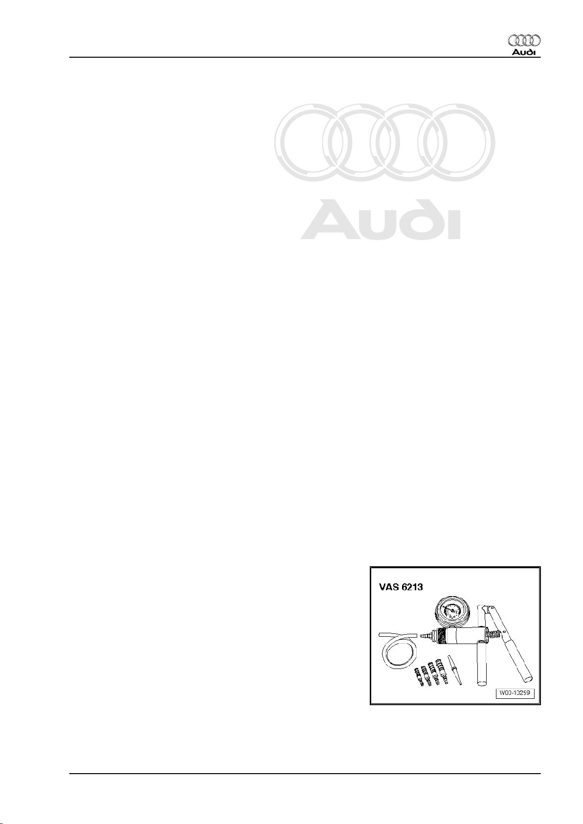
1.5 Checking vacuum system
Special tools and workshop equipment required
♦ Hand vacuum pump -VAS 6213-
Procedure
– Check all vacuum lines in the complete vacuum system for:
♦ Cracks
1. Safety precautions and rules for cleanliness 3
Page 8
Protected by copyright. Copying for private or commercial purposes, in part or in whole, is not
permitted unless authorised by AUDI AG. AUDI AG does not guarantee or accept any liability
with respect to the correctness of information in this document. Copyright by AUDI AG.
Audi TT 2007 ➤
TDI injection and glow plug system (4-cyl. 2.0 ltr. 4-valve common rail, generation II) - Edition 05.2010
♦ Traces of animal bites
♦ Kinked or crushed lines
♦ Lines porous or leaking
– Check vacuum line to solenoid valve and from solenoid valve
to corresponding component.
– If a fault is stored in the event memory, check all vacuum lines
leading to the corresponding component, and also check the
remaining vacuum lines leading to other components.
– If it is not possible to build up a vacuum with the hand vacuum
pump -VAS 6213- or if the vacuum pressure drops again im‐
mediately, check the hand vacuum pump and connecting
hoses for leaks.
4 Rep. Gr.23 - Mixture preparation - injection
Page 9
Protected by copyright. Copying for private or commercial purposes, in part or in whole, is not
permitted unless authorised by AUDI AG. AUDI AG does not guarantee or accept any liability
with respect to the correctness of information in this document. Copyright by AUDI AG.
Audi TT 2007 ➤
TDI injection and glow plug system (4-cyl. 2.0 ltr. 4-valve common rail, generation II) - Edition 05.2010
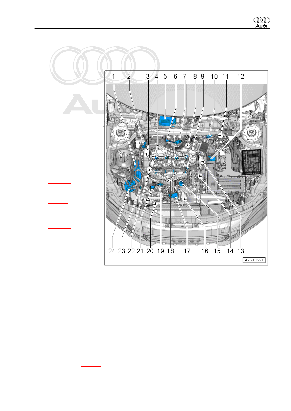
2 Overview of fitting locations
Components “A” to “H” are not shown in the illustration.
1 - Supplementary fuel pump V393-
❑ Exploded view ⇒ Rep.
Gr. 20
2 - Pressure differential sender
-G505-
❑ Exploded view
⇒ page 58
❑ Adaption must be per‐
formed after renewing
this component
3 - Hall sender -G40- (cam‐
shaft position sensor)
❑ Fitting location
⇒ page 10
❑ 10 Nm
4 - Injectors
❑ Exploded view
⇒ page 31
5 - Engine control unit -J623-
❑ Fitting location
⇒ page 7
6 - Lambda probe -G39- with
Lambda probe heater -Z19-
❑ Exploded view
⇒ page 58
❑ 50 Nm
7 - Position sender for charge
pressure positioner -G581-
❑ Fitting location
⇒ page 10
8 - Exhaust gas recirculation
control motor -V338- with exhaust gas recirculation potentiometer -G212-
❑ Integrated into exhaust gas recirculation cooler
❑ Fitting location ⇒ page 9
❑ Removing and installing ⇒ Engine, mechanics; Rep. Gr. 26
9 - Fuel pressure regulating valve -N276-
❑ Exploded view ⇒ page 43
❑ Checking ⇒ page 46
10 - Charge pressure control solenoid valve -N75-
❑ Fitting location ⇒ page 9
11 - Electrical connector
❑ For exhaust gas temperature sender 4 -G648❑ For exhaust gas temperature sender 1 -G235❑ For Lambda probe -G39❑ Fitting location ⇒ page 9
2. Overview of fitting locations 5
Page 10
Protected by copyright. Copying for private or commercial purposes, in part or in whole, is not
permitted unless authorised by AUDI AG. AUDI AG does not guarantee or accept any liability
with respect to the correctness of information in this document. Copyright by AUDI AG.
Audi TT 2007 ➤
TDI injection and glow plug system (4-cyl. 2.0 ltr. 4-valve common rail, generation II) - Edition 05.2010
12 - Coolant temperature sender -G62-
❑ Fitting location ⇒ page 10
13 - Air mass meter -G70-
❑ Exploded view ⇒ page 15
14 - Engine speed sender -G28-
❑ Fitting location ⇒ page 11
❑ 4.5 Nm
15 - Exhaust gas recirculation cooler change-over valve -N345-
❑ Fitting location ⇒ page 11
16 - Pump for exhaust gas recirculation cooler -V400-
❑ Fitting location ⇒ page 9
17 - Throttle valve module -J338- with throttle valve potentiometer -G69-
❑ Exploded view ⇒ page 21
18 - Glow plugs
❑ Glow plug 1 -Q10❑ Glow plug 2 -Q11❑ Glow plug 3 -Q12❑ Glow plug 4 -Q13❑ Removing and installing ⇒ page 67
❑ 17 Nm
19 - Fuel temperature sender -G81-
❑ In fuel supply line
❑ Fitting location ⇒ page 9
20 - Charge pressure sender -G31- with intake air temperature sender -G42-
❑ Fitting location ⇒ page 8
21 - High-pressure pump with fuel metering valve -N290-
❑ Exploded view ⇒ page 25
❑ Do not open fuel metering valve -N290❑ After renewing, first fuel filling operation MUST be performed (it is important not to allow pump to run
while it is still empty) ⇒ page 29
22 - Fuel pressure sender -G247-
❑ Exploded view ⇒ page 31
23 - Radiator outlet coolant temperature sender -G83-
❑ Fitting location ⇒ page 10
24 - Fuel filter
❑ Exploded view ⇒ Rep. Gr. 20
❑ Renewing ⇒ Rep. Gr. 20
A - Low heat output relay -J359- and high heat output relay -J360-
❑ Fitting location ⇒ Current flow diagrams, Electrical fault finding and Fitting locations
B - Brake light switch -F- and brake pedal switch -F47-
❑ Fitting location ⇒ page 7
C - Clutch position sender -G476-
❑ Fitting location ⇒ page 8
❑ Only fitted on vehicles with manual gearbox
D - Accelerator position sender -G79- and accelerator position sender 2 -G185-
❑ Fitting location ⇒ page 7
6 Rep. Gr.23 - Mixture preparation - injection
Page 11
Protected by copyright. Copying for private or commercial purposes, in part or in whole, is not
permitted unless authorised by AUDI AG. AUDI AG does not guarantee or accept any liability
with respect to the correctness of information in this document. Copyright by AUDI AG.
Audi TT 2007 ➤
TDI injection and glow plug system (4-cyl. 2.0 ltr. 4-valve common rail, generation II) - Edition 05.2010
E - Exhaust gas temperature sender 1 -G235-
❑ Exploded view ⇒ page 58
F - Exhaust gas temperature sender 3 -G495-
❑ Exploded view ⇒ page 58
G - Exhaust gas temperature sender 4 -G648-
❑ Exploded view ⇒ page 58
H - Particulate filter
❑ Combined with catalytic converter
❑ Adaption must be performed after renewing this component
❑ Removing and installing ⇒ Rep. Gr. 26
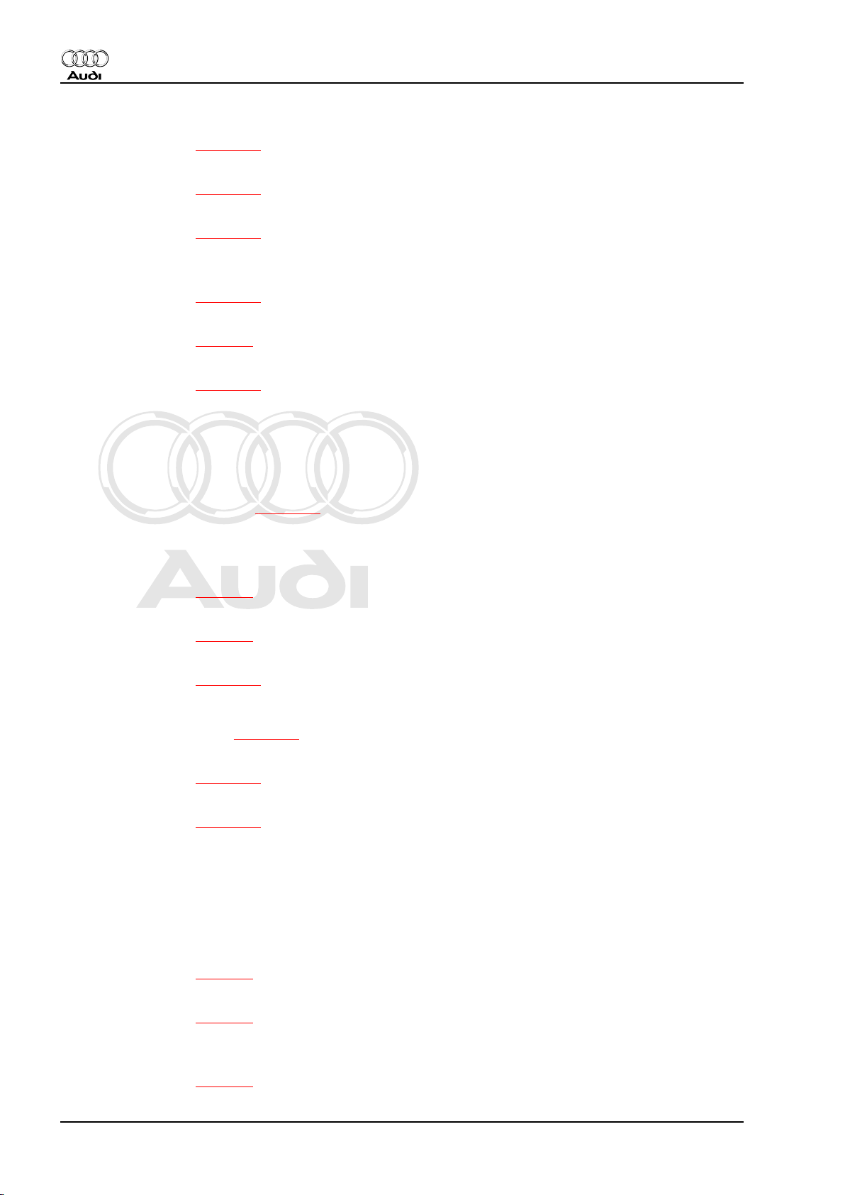
Fitting location of engine control unit -J623-
♦ In electronics box (plenum chamber)
Removing and installing ⇒ page 62
Fitting location: accelerator position sender -G79- and accelerator
position sender 2 -G185-
♦ Combined with accelerator pedal module
Note
The illustration shows the set-up for left-hand drive vehicles.
Removing and installing accelerator pedal module ⇒ Rep. Gr.
20
Fitting location of brake light switch -F- and brake pedal switch F47-
1 - Brake light switch -F- and brake pedal switch -F47-
♦ On brake master cylinder
Removing and installing ⇒ Rep. Gr. 47
2. Overview of fitting locations 7
Page 12
Protected by copyright. Copying for private or commercial purposes, in part or in whole, is not
permitted unless authorised by AUDI AG. AUDI AG does not guarantee or accept any liability
with respect to the correctness of information in this document. Copyright by AUDI AG.
Audi TT 2007 ➤
TDI injection and glow plug system (4-cyl. 2.0 ltr. 4-valve common rail, generation II) - Edition 05.2010
Fitting location of clutch position sender -G476-
♦ On clutch master cylinder-arrow-.
Removing and installing ⇒ Rep. Gr. 30
Integrated functions: clutch pedal switch for engine start -F194and clutch pedal switch -F36- (manual gearbox only)
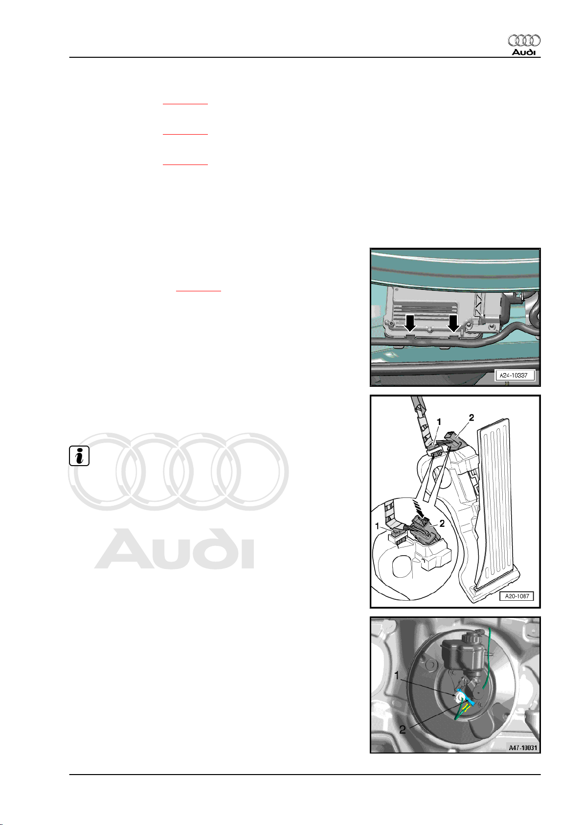
Fitting location of fuel pump control unit -J538-
1 - Connector for fuel pump control unit -J538-
2 - Fuel pump control unit -J538-
3 - Fuel system pressurisation pump -G6-
Removing and installing ⇒ Rep. Gr. 20
Fitting location of charge pressure sender -G31- with intake air
temperature sender -G42-
1 - Charge pressure sender -G31- with intake air temperature
sender -G42-
♦ At air pipe (right-side)
Removing and installing ⇒ Rep. Gr. 21
8 Rep. Gr.23 - Mixture preparation - injection
Page 13
Protected by copyright. Copying for private or commercial purposes, in part or in whole, is not
permitted unless authorised by AUDI AG. AUDI AG does not guarantee or accept any liability
with respect to the correctness of information in this document. Copyright by AUDI AG.
Audi TT 2007 ➤
TDI injection and glow plug system (4-cyl. 2.0 ltr. 4-valve common rail, generation II) - Edition 05.2010
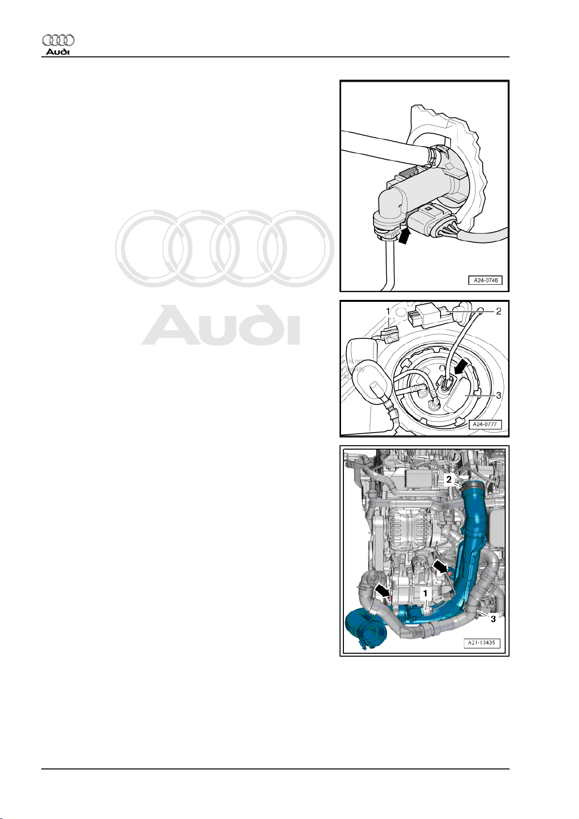
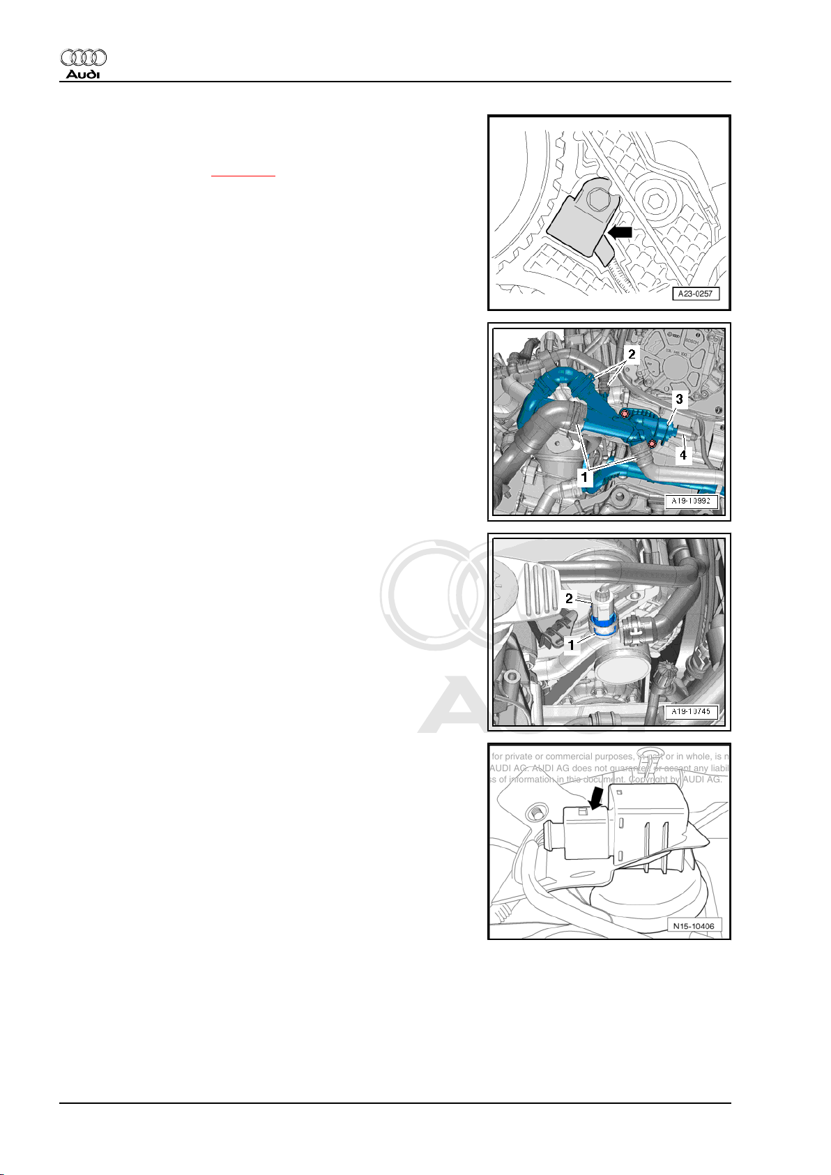
Components at rear of engine
2 - Exhaust gas recirculation control motor -V338- with exhaust
gas recirculation potentiometer -G212-
4 - Vacuum unit for exhaust gas recirculation cooling system
Electrical connectors
1 - For exhaust gas temperature sender 1 -G235-
2 - For exhaust gas temperature sender 4 -G648-
3 - For Lambda probe -G39-
4 - For exhaust gas temperature sender 3 -G495-
Fitting location of pump for exhaust gas recirculation cooler V400-
2 - Pump for exhaust gas recirculation cooler -V400-
♦ At front of engine
Removing and installing ⇒ Rep. Gr. 19
Fitting location of fuel temperature sender -G81-
4 - Fuel temperature sender -G81-
♦ In fuel supply line at high-pressure pump
2. Overview of fitting locations 9
Page 14
Protected by copyright. Copying for private or commercial purposes, in part or in whole, is not
permitted unless authorised by AUDI AG. AUDI AG does not guarantee or accept any liability
with respect to the correctness of information in this document. Copyright by AUDI AG.
Audi TT 2007 ➤
TDI injection and glow plug system (4-cyl. 2.0 ltr. 4-valve common rail, generation II) - Edition 05.2010
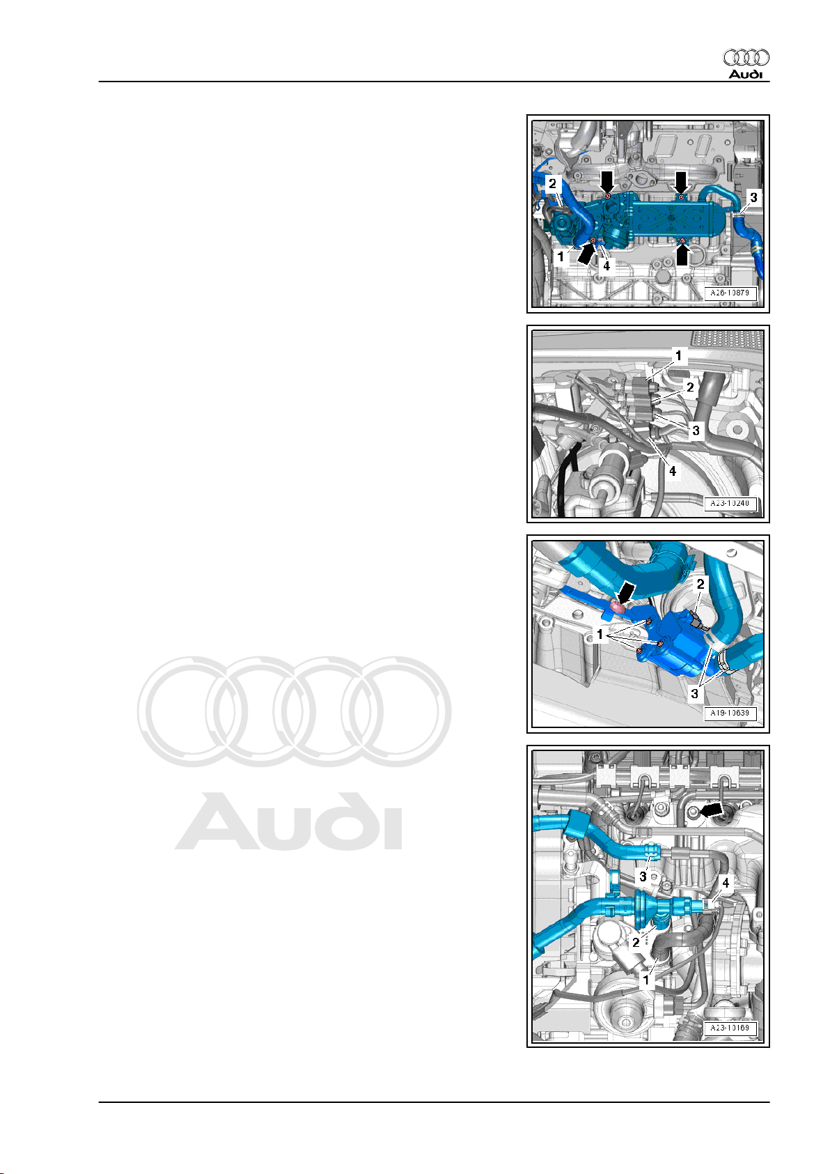
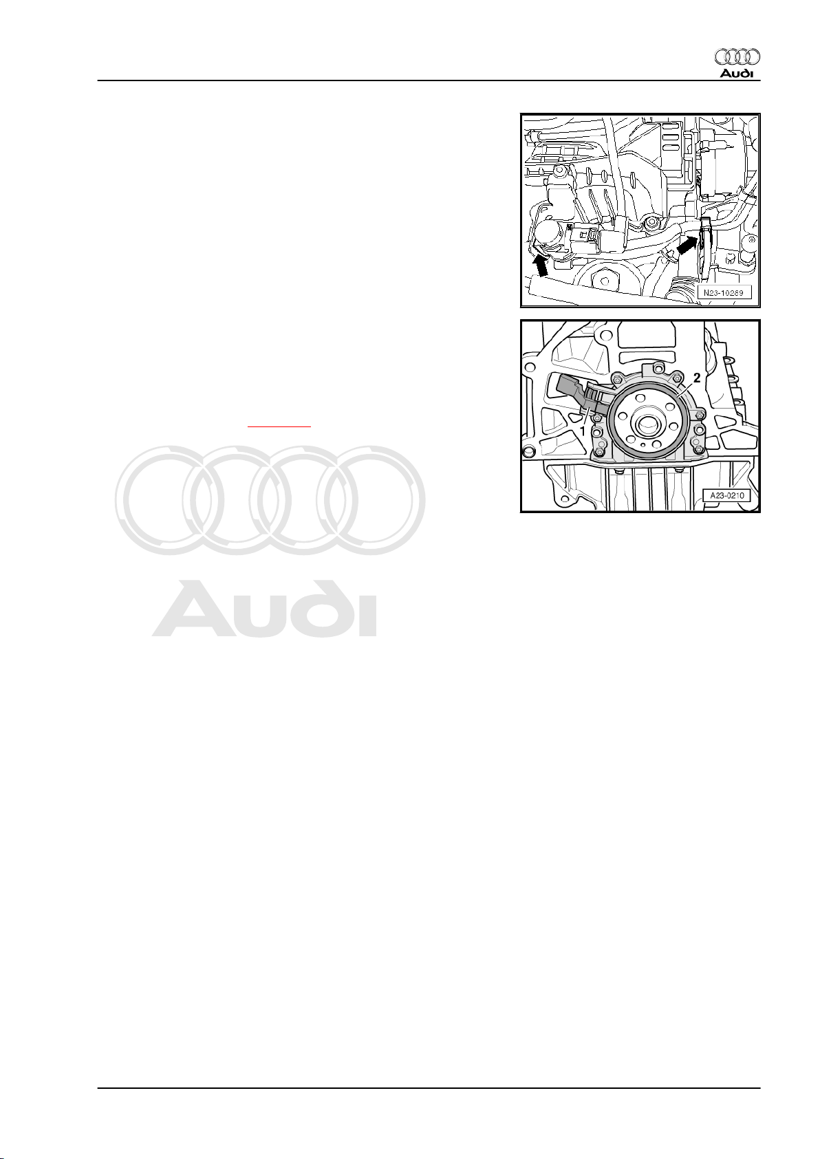
Fitting location of Hall sender -G40-
♦ Next to camshaft sprocket -arrow-
Removing and installing ⇒ page 69
Fitting location of coolant temperature sender -G62-
4 - Coolant temperature sender -G62-
♦ On right side of engine under exhauster pump
Removing and installing ⇒ Rep. Gr. 19
Fitting location of radiator outlet coolant temperature sender G83-
2 - Radiator outlet coolant temperature sender -G83-
♦ In coolant pipe (right-side) above alternator
Removing and installing ⇒ Rep. Gr. 19
Fitting location of position sender for charge pressure positioner
-G581-
♦ At rear of engine at turbocharger -arrow-.
10 Rep. Gr.23 - Mixture preparation - injection
Page 15
Protected by copyright. Copying for private or commercial purposes, in part or in whole, is not
permitted unless authorised by AUDI AG. AUDI AG does not guarantee or accept any liability
with respect to the correctness of information in this document. Copyright by AUDI AG.
Audi TT 2007 ➤
TDI injection and glow plug system (4-cyl. 2.0 ltr. 4-valve common rail, generation II) - Edition 05.2010
Fitting location of exhaust gas recirculation cooler change-over
valve -N345-
♦ On intake manifold -left arrow-.
Fitting location of engine speed sender -G28-
1 - Engine speed sender -G28-
2 - Sender wheel
♦ On flywheel side of engine.
Removing and installing ⇒ page 70
2. Overview of fitting locations 11
Page 16
Protected by copyright. Copying for private or commercial purposes, in part or in whole, is not
permitted unless authorised by AUDI AG. AUDI AG does not guarantee or accept any liability
with respect to the correctness of information in this document. Copyright by AUDI AG.
Audi TT 2007 ➤
TDI injection and glow plug system (4-cyl. 2.0 ltr. 4-valve common rail, generation II) - Edition 05.2010
3 System layout
WARNING
♦ Always read rules for cleanliness and instructions for
working on fuel system ⇒ page 2 .
♦ Follow these instructions and rules for cleanliness before
starting work and while working on the fuel system.
Caution
The high-pressure fuel pump has very close tolerances and
must not be allowed to run without fuel. To prevent this and to
enable the engine to start quickly after parts have been re‐
newed, it is important to observe the following:
♦ If components of the fuel system between the fuel tank
and the high-pressure pump are removed or renewed, the
first fuel filling operation must be performed.
♦ If a fuel pump, fuel line (between fuel tank and high-pres‐
sure pump) or fuel filter is removed or renewed, the fuel
system must be bled before the engine is started for the
first time.
♦ If the high-pressure pump is removed or renewed, the fuel
system must be bled before the engine is started for the
first time.
Procedure for first fuel filling ⇒ page 29
Note
The high-pressure pump will be damaged if the first fuel filling
procedure is not performed.
12 Rep. Gr.23 - Mixture preparation - injection
Page 17
Protected by copyright. Copying for private or commercial purposes, in part or in whole, is not
permitted unless authorised by AUDI AG. AUDI AG does not guarantee or accept any liability
with respect to the correctness of information in this document. Copyright by AUDI AG.
Audi TT 2007 ➤
TDI injection and glow plug system (4-cyl. 2.0 ltr. 4-valve common rail, generation II) - Edition 05.2010
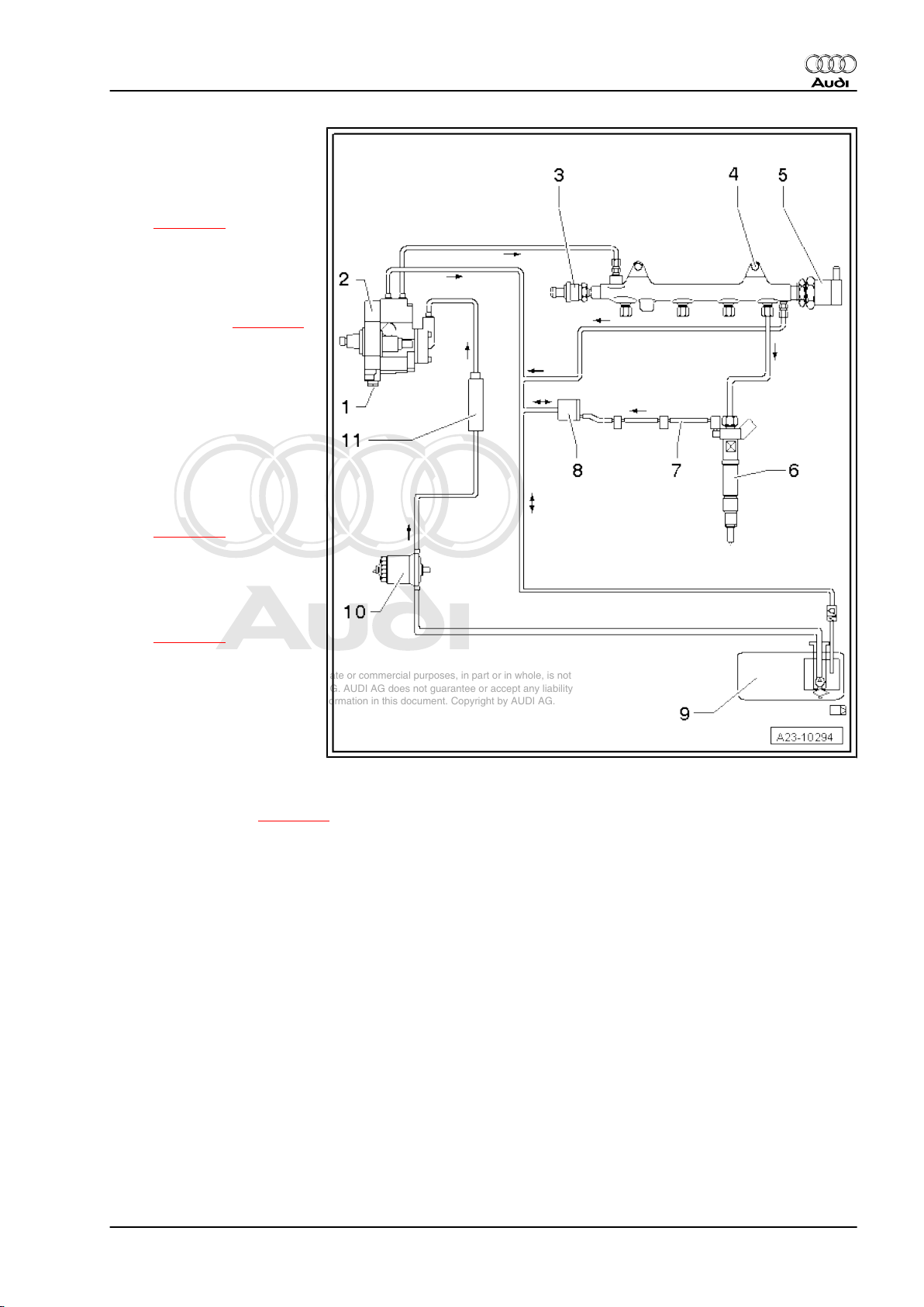
1 - Fuel metering valve -N290-
❑ Do not unscrew
2 - High-pressure pump
❑ Exploded view
⇒ page 25
❑ After renewing, first fuel
filling operation MUST
be performed (it is im‐
portant not to allow
pump to run while it is
still empty) ⇒ page 29
❑ After renewing high-
pressure pump or fuel
pressure regulating
valve -N276- , learnt val‐
ues must be re-adapted;
see “Guided Functions”
in vehicle diagnostic
tester
3 - Fuel pressure sender G247-
❑ Exploded view
⇒ page 31
4 - Fuel rail
5 - Fuel pressure regulating
valve -N276-
❑ Exploded view
⇒ page 31
❑ After renewing high-
pressure pump or fuel
pressure regulating
valve -N276- , learnt val‐
ues must be re-adapted;
see “Guided Functions”
in vehicle diagnostic
tester
6 - Injector
❑ Exploded view ⇒ page 31
7 - Fuel return line
8 - Not fitted
9 - Fuel tank
❑ With fuel system pressurisation pump -G6-
10 - Fuel filter
❑ Exploded view ⇒ Rep. Gr. 20
11 - Supplementary fuel pump -V393-
❑ Exploded view ⇒ Rep. Gr. 20
3. System layout 13
Page 18
Protected by copyright. Copying for private or commercial purposes, in part or in whole, is not
permitted unless authorised by AUDI AG. AUDI AG does not guarantee or accept any liability
with respect to the correctness of information in this document. Copyright by AUDI AG.
Audi TT 2007 ➤
TDI injection and glow plug system (4-cyl. 2.0 ltr. 4-valve common rail, generation II) - Edition 05.2010
4 Bleeding fuel system
Caution
If components of the fuel system between the fuel tank and the
high-pressure fuel pump are removed or renewed, the basic
setting “Checking fuel system pressurisation pump” must be
performed to bleed the fuel system.
If the supplementary fuel pump, fuel line (between fuel tank
and high-pressure fuel pump) or fuel filter is removed or re‐
newed, the basic setting “Checking fuel system pressurisation
pump” must be performed before the engine is started for the
first time.
Proceed as follows to fill fuel system with fuel:
– Connect a vehicle diagnostic tester.
– Switch on ignition.
– Select “Engine electronics” in vehicle self-diagnosis.
– Then select “Basic setting”.
– Select “Checking fuel system pressurisation pump” from the
list.
– Press “Start” button.
– The fuel pumps start running.
– The fuel pumps must run for approx. 1 minute to ensure that
the fuel system is filled sufficiently with fuel.
Note
To repeat basic setting, switch ignition off and on once. Then start
basic setting again.
– Start engine after filling fuel system.
– Run engine at moderate speed for several minutes and then
switch off.
– Check fuel system for leaks.
– Erase entry in event memory using diagnostic tester.
– After completing the repair, road-test the vehicle over a dis‐
tance of at least 20 km. Accelerate with full throttle at least
once. Then inspect the high-pressure section of the fuel sys‐
tem again for leaks.
Note
If there is any air left in the fuel system, the engine may switch to
the backup mode ('emergency running' mode) during the road
test. Switch off the engine and erase the event memory. Then
continue the road test.
– Interrogate event memory.
14 Rep. Gr.23 - Mixture preparation - injection
Page 19
Protected by copyright. Copying for private or commercial purposes, in part or in whole, is not
permitted unless authorised by AUDI AG. AUDI AG does not guarantee or accept any liability
with respect to the correctness of information in this document. Copyright by AUDI AG.
Audi TT 2007 ➤
TDI injection and glow plug system (4-cyl. 2.0 ltr. 4-valve common rail, generation II) - Edition 05.2010
5 Air cleaner
⇒ “5.1 Air cleaner - exploded view”, page 15
⇒ “5.2 Removing and installing engine cover panel”, page 16
⇒ “5.3 Removing and installing air filter element”, page 17
⇒ “5.4 Removing and installing air cleaner housing”, page 18
⇒ “5.5 Removing and installing air mass meter G70 ”, page 20
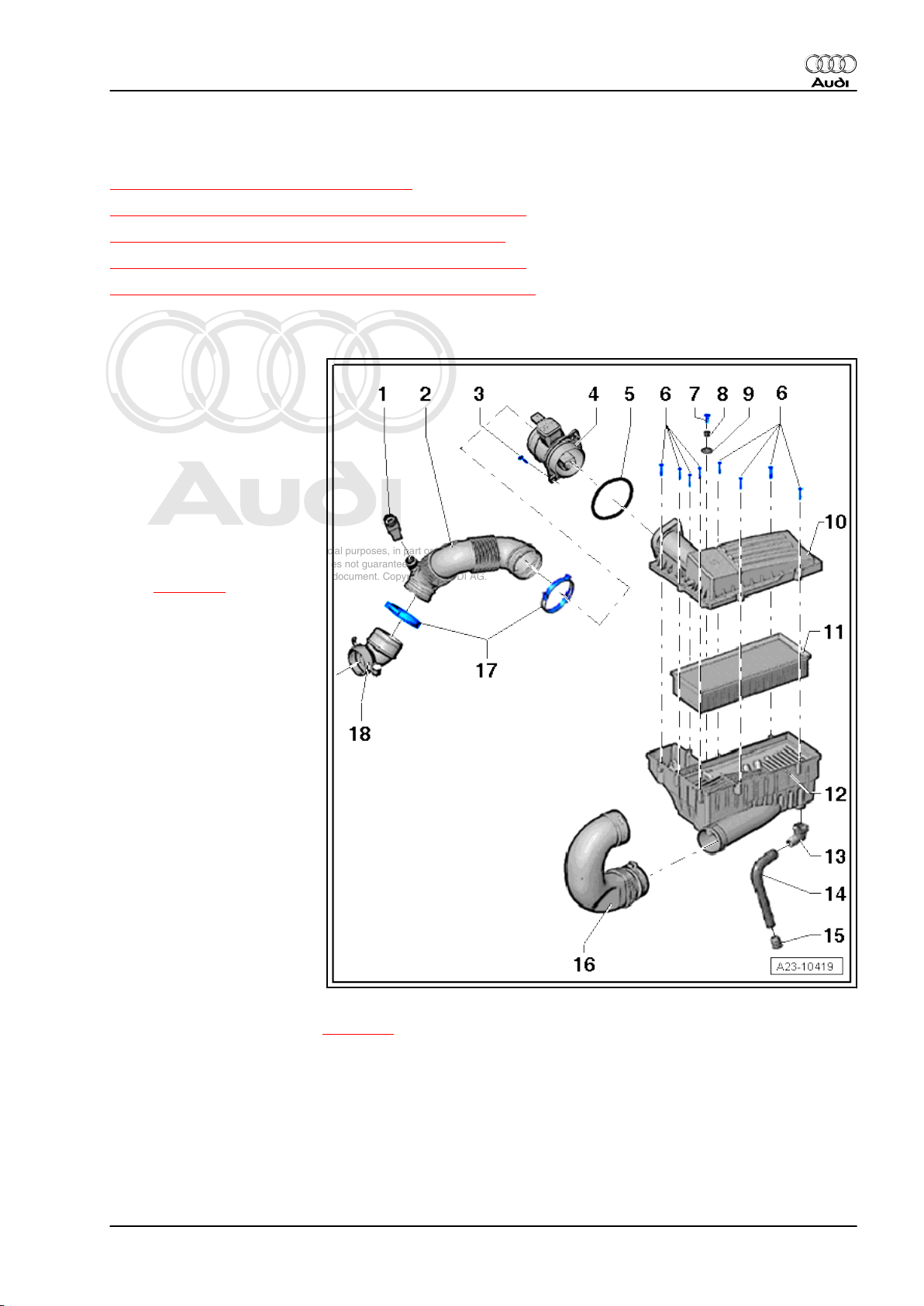
5.1 Air cleaner - exploded view
1 - Hose connection
2 - Air hose
❑ To turbocharger
❑ Check for dirt and accu‐
mulated leaves, etc.
3 - Bolt
❑ 2x
❑ 1.5 Nm
4 - Air mass meter -G70-
❑ Removing and installing
⇒ page 20
5 - O-ring
❑ Renew
❑ Use silicone-free lubri‐
cant when installing
6 - Bolts
❑ For air cleaner (top sec‐
tion)
❑ 1.5 Nm
7 - Bolt
❑ For air cleaner (bottom
section)
❑ 8 Nm
8 - Sleeve
9 - Washer
10 - Air cleaner (top section)
❑ Clean out dirt, leaves
and salt deposits
11 - Air filter element
❑ Always use genuine part for air filter element
❑ Removing and installing ⇒ page 17
❑ Observe change intervals ⇒ Maintenance ; Booklet 810
12 - Air cleaner (bottom section)
❑ Clean out dirt, leaves and salt deposits
❑ On vehicles for cold climates, air cleaner (bottom section) with hot-air-intake hose is installed
❑ Country-specific version with snow screen
13 - Connection for water drain hose
❑ Clean
5. Air cleaner 15
Page 20
Protected by copyright. Copying for private or commercial purposes, in part or in whole, is not
permitted unless authorised by AUDI AG. AUDI AG does not guarantee or accept any liability
with respect to the correctness of information in this document. Copyright by AUDI AG.
Audi TT 2007 ➤
TDI injection and glow plug system (4-cyl. 2.0 ltr. 4-valve common rail, generation II) - Edition 05.2010
14 - Water drain hose
❑ Clean
15 - Flutter valve
❑ Clean and re-install
16 - Intake air duct
❑ To lock carrier
❑ Clean out dirt, leaves and salt deposits
17 - Spring-type clip
18 - Connecting hose
❑ To turbocharger
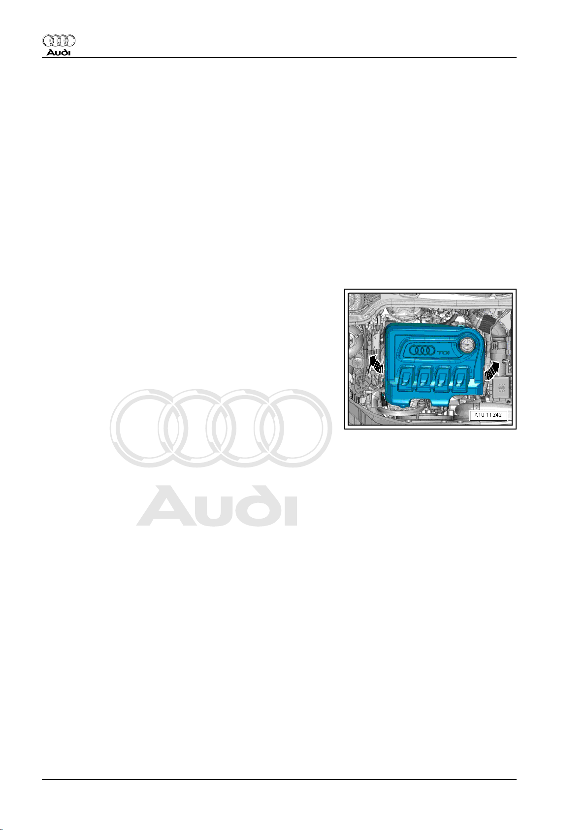
5.2 Removing and installing engine cover panel
Removing
– Carefully pull engine cover panel off retaining pins one after
the other -arrows-. Do not jerk the cover panel away, and do
not try to pull on one side only.
Installing
– To avoid damage, do not strike the engine cover panel with
your fist or with any kind of tool.
– Position engine cover panel on engine (note locations of oil
filler neck and oil dipstick).
– Press engine cover panel with both hands into the rubber
grommets at the rear and then into the grommets at the front.
16 Rep. Gr.23 - Mixture preparation - injection
Page 21
Protected by copyright. Copying for private or commercial purposes, in part or in whole, is not
permitted unless authorised by AUDI AG. AUDI AG does not guarantee or accept any liability
with respect to the correctness of information in this document. Copyright by AUDI AG.
Audi TT 2007 ➤
TDI injection and glow plug system (4-cyl. 2.0 ltr. 4-valve common rail, generation II) - Edition 05.2010
5.3 Removing and installing air filter ele‐
ment
Removing
– Remove bolts -arrows-.
Note
Disregard -items 1, 2, 3-.
– Lift up air cleaner (top section) and take out air filter element.
Installing
• Tightening torque
⇒ “5.1 Air cleaner - exploded view”, page 15
To ensure that the air mass meter functions properly, it is impor‐
tant to observe the following notes and instructions.
Note
♦
If the air filter element is very dirty or wet, dirt or water could
reach the air mass meter and affect the air mass value. This
would lead to loss of power, since a smaller injection quantity
is calculated.
♦
Always use genuine part for air filter element.
♦
The air cleaner housing MUST be clean.
♦
To prevent malfunctions, cover critical parts of the engine air
intake (air mass meter, air pipes, etc.) with a clean cloth when
blowing out the air cleaner housing with compressed air.
♦
Observe environmental requirements for disposal.
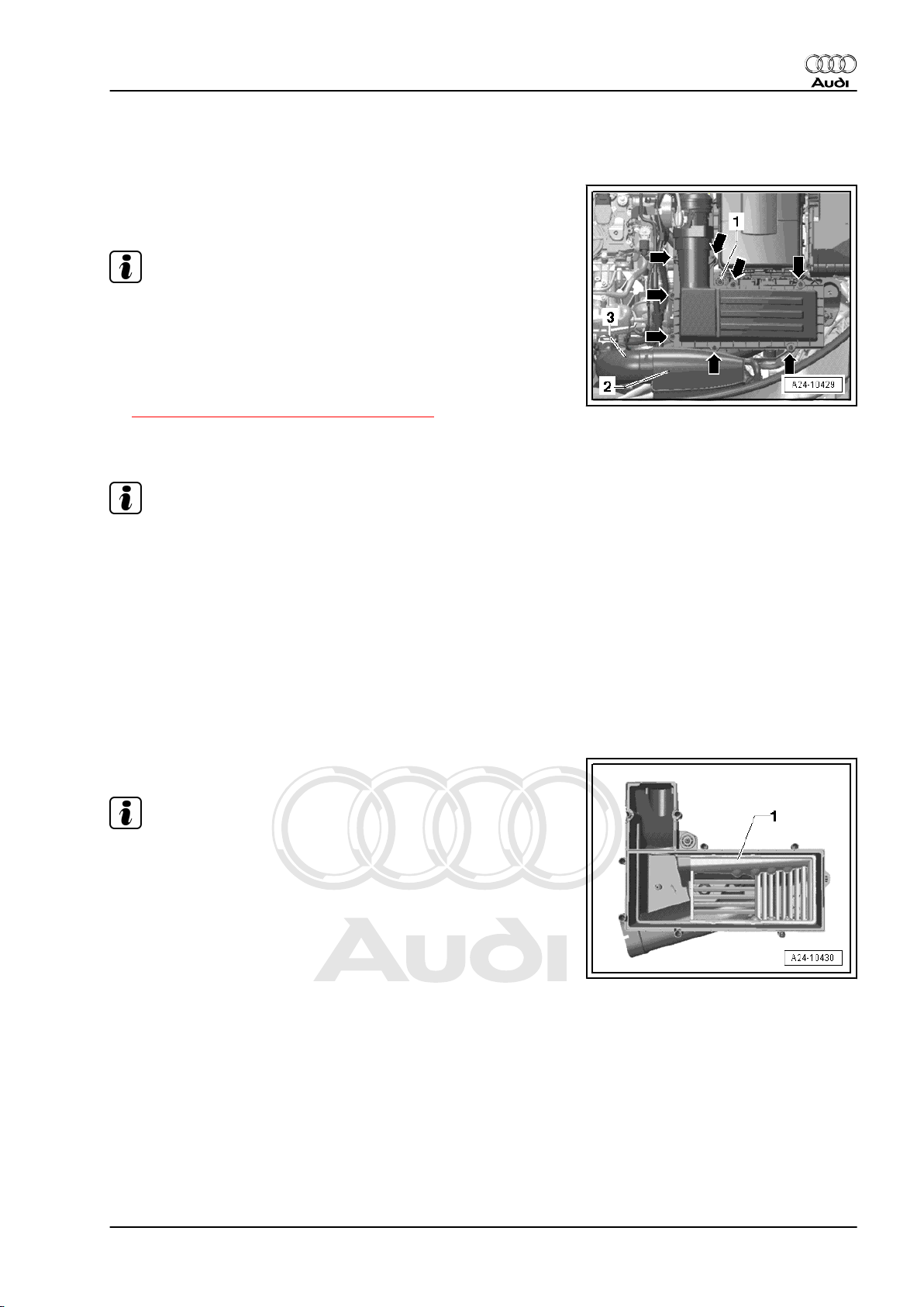
– Remove snow screen -1- and clean it.
Note
The snow screen is not fitted on all vehicles.
5. Air cleaner 17
Page 22
Protected by copyright. Copying for private or commercial purposes, in part or in whole, is not
permitted unless authorised by AUDI AG. AUDI AG does not guarantee or accept any liability
with respect to the correctness of information in this document. Copyright by AUDI AG.
Audi TT 2007 ➤
TDI injection and glow plug system (4-cyl. 2.0 ltr. 4-valve common rail, generation II) - Edition 05.2010
– Clean water drain -arrow- and air cleaner (bottom section).
– Clean salt residue, dirt and leaves out of air cleaner housing
(top and bottom sections) using a vacuum cleaner.
– Check for salt residue, dirt and leaves in air mass meter and
air intake hose (engine intake side).
– Check for dirt and leaves in air duct going from lock carrier to
air cleaner housing.
– When installing air filter element, check that it is properly cen‐
tred in retainer in air cleaner (bottom section).
– Fit the top section of the air cleaner carefully on the bottom
section, without using force. Make sure the top section of the
air cleaner is fitted straight on the air filter element (note posi‐
tion of sealing lip on air filter element).
– Ensure secure fit of intake hose at air mass meter.
The remaining installation steps are carried out in the reverse se‐
quence.
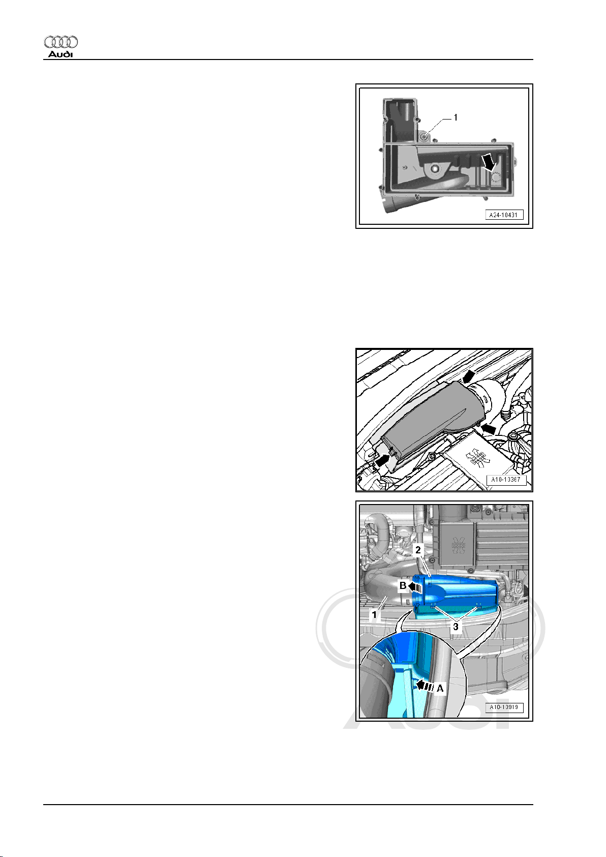
5.4 Removing and installing air cleaner housing
Removing
– Pull cover off air duct (release clips on sides) -arrows-.
– Release clips on left and right -arrow A- and unclip air duct at
bottom -2-.
– Swivel air duct (bottom) slightly to the rear and detach air duct
(bottom) from retainers -3-.
– Detach air pipe -1- from air duct (bottom) -arrow B-.
18 Rep. Gr.23 - Mixture preparation - injection
Page 23
Protected by copyright. Copying for private or commercial purposes, in part or in whole, is not
permitted unless authorised by AUDI AG. AUDI AG does not guarantee or accept any liability
with respect to the correctness of information in this document. Copyright by AUDI AG.
Audi TT 2007 ➤
TDI injection and glow plug system (4-cyl. 2.0 ltr. 4-valve common rail, generation II) - Edition 05.2010
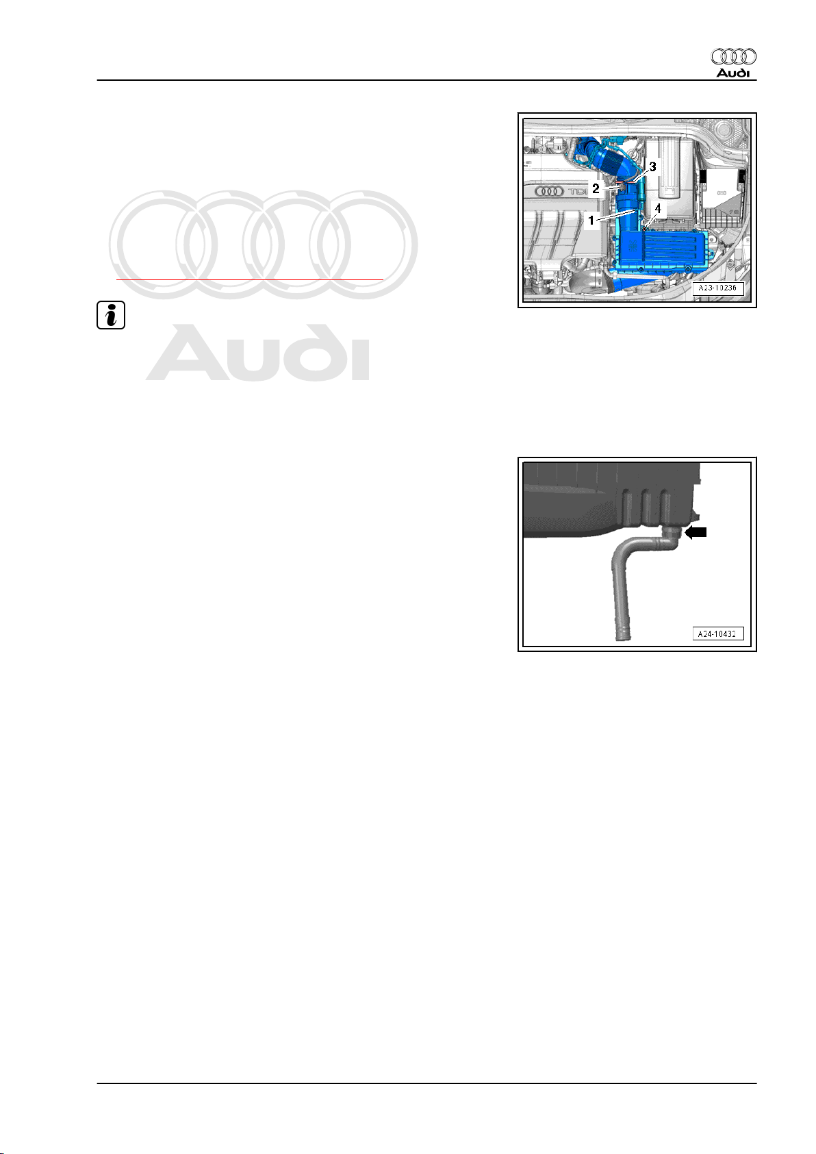
– Unplug electrical connector -2- from air mass meter -G70- .
– Detach hose -1-.
– Release hose clip -3- and detach air hose.
– Unscrew bolt -4- and remove air cleaner housing.
Installing
Installation is carried out in the reverse order; note the following:
• Tightening torque
⇒ “5.1 Air cleaner - exploded view”, page 15
Note
♦
Hose connections and air pipes and hoses must be free of oil
and grease before assembly.
♦
Use silicone-free lubricant when installing air hose.
♦
Secure all hose connections with the correct type of hose clips
(same as original equipment) ⇒ Electronic parts catalogue .
– Disconnect water drain hose -arrow- from air cleaner (bottom
section) and clean any dirt or leaves out of connection and
hose.
5. Air cleaner 19
Page 24

Protected by copyright. Copying for private or commercial purposes, in part or in whole, is not
permitted unless authorised by AUDI AG. AUDI AG does not guarantee or accept any liability
with respect to the correctness of information in this document. Copyright by AUDI AG.
Audi TT 2007 ➤
TDI injection and glow plug system (4-cyl. 2.0 ltr. 4-valve common rail, generation II) - Edition 05.2010
5.5 Removing and installing air mass meter
-G70-
Removing
– Remove air cleaner housing ⇒ page 18 .
– Remove bolts -arrows-.
– Carefully pull air mass meter -G70- out of guide on air cleaner
housing.
Installing
• Tightening torque
⇒ “5.1 Air cleaner - exploded view”, page 15
To ensure the proper function of the air mass meter -G70- it is
important to observe the following instructions.
Note
♦
If the air filter element is very dirty or wet, dirt or water could
reach the air mass meter and affect the air mass value. This
would lead to loss of power, since a smaller injection quantity
is calculated.
♦
Always use genuine part for air filter element.
♦
Always renew seal if damaged (air leaks in intake system).
♦
Use a silicone-free lubricant when installing the air hose and
seal.
♦
Hose connections and air pipes and hoses must be free of oil
and grease before assembly.
♦
Secure all hose connections with the correct type of hose clips
(same as original equipment) ⇒ Electronic parts catalogue .
– Check for salt residue, dirt and leaves in air mass meter and
air intake hose (engine intake side).
– Check for dirt in air duct leading to air filter element. If neces‐
sary, clean salt residue, dirt and leaves out of air cleaner
housing (top and bottom sections); wash out or use a vacuum
cleaner as required.
– Install air cleaner housing ⇒ page 18 .
20 Rep. Gr.23 - Mixture preparation - injection
Page 25

Protected by copyright. Copying for private or commercial purposes, in part or in whole, is not
permitted unless authorised by AUDI AG. AUDI AG does not guarantee or accept any liability
with respect to the correctness of information in this document. Copyright by AUDI AG.
Audi TT 2007 ➤
TDI injection and glow plug system (4-cyl. 2.0 ltr. 4-valve common rail, generation II) - Edition 05.2010
6 Intake manifold
⇒ “6.1 Intake manifold with attached components - exploded
view”, page 21
⇒ “6.2 Removing and installing intake manifold”, page 22
6.1 Intake manifold with attached components - exploded view
1 - Guide tube
❑ For oil dipstick
2 - Seal
❑ Renew
3 - Gasket
❑ Renew
4 - Bolt
❑ 8 Nm
5 - Fuel return line
6 - Bolt
❑ 9 Nm
7 - Intake manifold
❑ With intake manifold
flap motor -V157- and
intake manifold flap po‐
tentiometer -G336❑ Must not be dismantled
❑ Removing and installing
⇒ page 22
8 - Bracket
❑ For exhaust gas recircu‐
lation cooler change-
over valve -N345-
9 - Bolt
❑ 9 Nm
10 - Exhaust gas recirculation
cooler change-over valve N345-
11 - Gasket
❑ Renew
12 - Bolt
❑ 20 Nm
13 - Connecting pipe
❑ To exhaust gas recirculation cooler
14 - Clamp
❑ Renew
❑ 5 Nm
15 - Connection
❑ For exhaust gas recirculation
16 - Bolt
❑ 8 Nm
6. Intake manifold 21
Page 26

Protected by copyright. Copying for private or commercial purposes, in part or in whole, is not
permitted unless authorised by AUDI AG. AUDI AG does not guarantee or accept any liability
with respect to the correctness of information in this document. Copyright by AUDI AG.
Audi TT 2007 ➤
TDI injection and glow plug system (4-cyl. 2.0 ltr. 4-valve common rail, generation II) - Edition 05.2010
17 - Seal
❑ Renew
18 - Throttle valve module -J338-
❑ With throttle valve potentiometer -G69❑ Removing and installing ⇒ page 43
19 - Bolt
❑ 8 Nm
20 - Bolt
❑ 9 Nm
21 - Clip
6.2 Removing and installing intake manifold
Special tools and workshop equipment required
♦ Socket T30 -T10405-
Removing
WARNING
♦ Always read rules for cleanliness and instructions for
working on fuel system ⇒ page 2 .
♦ Follow these instructions and rules for cleanliness before
starting work and while working on the fuel system.
– Remove engine cover panel ⇒ page 16 .
– Loosen hose clip -arrow-.
– Detach electrical connectors at glow plugs ⇒ page 67 .
22 Rep. Gr.23 - Mixture preparation - injection
Page 27

Protected by copyright. Copying for private or commercial purposes, in part or in whole, is not
permitted unless authorised by AUDI AG. AUDI AG does not guarantee or accept any liability
with respect to the correctness of information in this document. Copyright by AUDI AG.
Audi TT 2007 ➤
TDI injection and glow plug system (4-cyl. 2.0 ltr. 4-valve common rail, generation II) - Edition 05.2010
– Take exhaust gas recirculation cooler change-over valve -
N345- -left arrow- out of bracket and move clear to one side.
Note
Disregard -arrow- on right-side of illustration.
– Remove bolts -2- and place coolant return line to one side.
– Remove bolts -arrows- and place fuel return line to one side.
– Remove bolt -2- and union nuts -1 and 3- and detach high-
pressure pipe.
– Remove fuel rail ⇒ page 55 .
6. Intake manifold 23
Page 28

Protected by copyright. Copying for private or commercial purposes, in part or in whole, is not
permitted unless authorised by AUDI AG. AUDI AG does not guarantee or accept any liability
with respect to the correctness of information in this document. Copyright by AUDI AG.
Audi TT 2007 ➤
TDI injection and glow plug system (4-cyl. 2.0 ltr. 4-valve common rail, generation II) - Edition 05.2010
– Unplug electrical connector -2- at throttle valve module -
J338- .
– Remove bolt -1- for dipstick guide tube.
Note
Disregard -arrows-.
– Open clamp -1- and detach.
Note
Disregard -item 2-.
– Unscrew intake manifold bolts -arrows- in diagonal sequence
starting from outside and working inwards using socket T30 T10405- .
– Carefully take out intake manifold.
Installing
Installation is carried out in the reverse order; note the following:
• Tightening torque
⇒ “6.1 Intake manifold with attached components - exploded
view”, page 21
Note
Renew seals and/or gaskets.
– Tighten intake manifold bolts in diagonal sequence, working
from inside to outside.
– Install air pipe ⇒ Rep. Gr. 21 .
– Install fuel rail ⇒ page 55 .
24 Rep. Gr.23 - Mixture preparation - injection
Page 29

Protected by copyright. Copying for private or commercial purposes, in part or in whole, is not
permitted unless authorised by AUDI AG. AUDI AG does not guarantee or accept any liability
with respect to the correctness of information in this document. Copyright by AUDI AG.
Audi TT 2007 ➤
TDI injection and glow plug system (4-cyl. 2.0 ltr. 4-valve common rail, generation II) - Edition 05.2010
7 High-pressure pump
⇒ “7.1 High-pressure pump - exploded view”, page 25
⇒ “7.2 Removing and installing high-pressure pump”, page 26
⇒ “7.3 Performing first fuel filling operation after installing highpressure pump”, page 29
⇒ “7.4 Checking fuel system for leaks”, page 30
7.1 High-pressure pump - exploded view
1 - Bracket for ancillaries
❑ Removing and installing
⇒ Rep. Gr. 13
2 - Bolt
❑ 2x
❑ Renew
❑ 20 Nm + 180° further
3 - Hub
❑ Use counterhold tool -
T10051- when loosen‐
ing and tightening
❑ To remove, use puller -
T40064-
4 - High-pressure pump
sprocket
5 - Bolt
❑ 3x
❑ Renew
❑ 20 Nm + 90° further
6 - Nut
❑ 95 Nm
7 - Bolt
❑ Renew
❑ 20 Nm + 45° further
8 - High-pressure pump
❑ With fuel metering valve
-N290- (do not open)
❑ After renewing, first fuel
filling operation MUST
be performed (it is im‐
portant not to allow
pump to run while it is still empty) ⇒ page 29
❑ After renewing high-pressure pump or fuel pressure regulating valve -N276- , learnt values must be re-
adapted; see “Guided Functions” in vehicle diagnostic tester
❑ Removing and installing ⇒ page 26
9 - Fuel supply hose
10 - Fuel return hose
11 - High-pressure pipes
❑ Between high-pressure pump and fuel rail
❑ Do not interchange
7. High-pressure pump 25
Page 30

Protected by copyright. Copying for private or commercial purposes, in part or in whole, is not
permitted unless authorised by AUDI AG. AUDI AG does not guarantee or accept any liability
with respect to the correctness of information in this document. Copyright by AUDI AG.
Audi TT 2007 ➤
TDI injection and glow plug system (4-cyl. 2.0 ltr. 4-valve common rail, generation II) - Edition 05.2010
Note
❑ Install free of stress
❑ Tightening torque ⇒ Item 9 (page 32)
7.2 Removing and installing high-pressure
pump
Special tools and workshop equipment required
♦ Counterhold tool -T10051-
♦ Puller -T40064- with T40064/1
Removing
Caution
♦ Always observe rules for cleanliness and instructions for
working on fuel system ⇒ page 2 .
♦ Follow these instructions and rules for cleanliness before
starting work and while working on the fuel system.
Running when dry causes irreparable damage to high-pres‐
sure pump.
♦ The high-pressure pump must first be filled with fuel before
the engine is started. The high-pressure pump must not
be allowed to run while still empty. First fuel filling
⇒ page 29
26 Rep. Gr.23 - Mixture preparation - injection
Page 31

Protected by copyright. Copying for private or commercial purposes, in part or in whole, is not
permitted unless authorised by AUDI AG. AUDI AG does not guarantee or accept any liability
with respect to the correctness of information in this document. Copyright by AUDI AG.
Audi TT 2007 ➤
TDI injection and glow plug system (4-cyl. 2.0 ltr. 4-valve common rail, generation II) - Edition 05.2010
– Remove toothed belt from camshaft and high-pressure pump
⇒ Rep. Gr. 15 .
– Remove bolts -2- and detach toothed belt sprocket from high-
pressure pump.
Note
Disregard -item 1-.
– Counterhold using counterhold tool -T10051- and remove nut
-1- at hub of high-pressure pump.
– Apply puller -T40064- with thrust piece -T40064/1- and pin -
T40064/2- as shown in illustration and pull hub off high-pres‐
sure pump. If necessary, counterhold using an open-end
spanner (24 mm).
7. High-pressure pump 27
Page 32

Protected by copyright. Copying for private or commercial purposes, in part or in whole, is not
permitted unless authorised by AUDI AG. AUDI AG does not guarantee or accept any liability
with respect to the correctness of information in this document. Copyright by AUDI AG.
Audi TT 2007 ➤
TDI injection and glow plug system (4-cyl. 2.0 ltr. 4-valve common rail, generation II) - Edition 05.2010
– Remove bolts -2- and place coolant return line to one side.
Note
Disregard -items 1, 3-.
– Remove bolts -arrows- and place fuel return line to one side.
– Remove bolt -2- and union nuts -1 and 3- and detach high-
pressure pipe.
– Unplug electrical connectors -1- and -3-.
– Detach fuel supply hose -2- and fuel return hose -4-.
28 Rep. Gr.23 - Mixture preparation - injection
Page 33

Protected by copyright. Copying for private or commercial purposes, in part or in whole, is not
permitted unless authorised by AUDI AG. AUDI AG does not guarantee or accept any liability
with respect to the correctness of information in this document. Copyright by AUDI AG.
Audi TT 2007 ➤
TDI injection and glow plug system (4-cyl. 2.0 ltr. 4-valve common rail, generation II) - Edition 05.2010
– Remove bolts -arrows- for high-pressure pump.
– Carefully take out high-pressure pump.
Installing
Installation is carried out in the reverse order; note the following:
• Tightening torques
⇒ “7.1 High-pressure pump - exploded view”, page 25
– Install toothed belt ⇒ Rep. Gr. 15 .
– Install high-pressure pipe ⇒ page 45 .
Caution
Running when dry causes irreparable damage to high-pres‐
sure pump.
♦ The high-pressure pump must first be filled with fuel before
the engine is started. The high-pressure pump must not
be allowed to run while still empty. First fuel filling
⇒ page 29
7.3 Performing first fuel filling operation af‐
ter installing high-pressure pump
Caution
Running when dry causes irreparable damage to high-pres‐
sure pump.
♦ The high-pressure pump must first be filled with fuel before
the engine is started. The high-pressure pump must not
be allowed to run while still empty.
Note
♦
When installing the high-pressure fuel pump, it is essential to
ensure that no dirt enters the fuel system.
♦
Only remove sealing plugs immediately prior to installation of
fuel pipes.
♦
There must be sufficient fuel in the tank.
– Connect vehicle diagnostic tester.
– Switch on ignition.
– Select “Engine electronics” in vehicle self-diagnosis.
– Then select “Basic setting”.
– Select “Checking fuel system pressurisation pump” from the
list.
– The fuel pumps start running.
– The fuel pumps must run for approx. 1 minute to ensure that
the high-pressure pump is filled with sufficient fuel.
– Start engine after filling fuel system.
– Run engine at moderate speed for several minutes and then
switch off.
7. High-pressure pump 29
Page 34

Protected by copyright. Copying for private or commercial purposes, in part or in whole, is not
permitted unless authorised by AUDI AG. AUDI AG does not guarantee or accept any liability
with respect to the correctness of information in this document. Copyright by AUDI AG.
Audi TT 2007 ➤
TDI injection and glow plug system (4-cyl. 2.0 ltr. 4-valve common rail, generation II) - Edition 05.2010
– Check fuel system for leaks.
– Erase entry in event memory using vehicle diagnostic tester.
– After completing the repair, road-test the vehicle over a dis‐
tance of at least 20 km. Accelerate with full throttle at least
once. Then inspect the high-pressure section of the fuel sys‐
tem again for leaks.
Note
If there is any air left in the fuel system, the engine may switch to
the backup mode ('emergency running' mode) during the road
test. Switch off the engine and erase the event memory. Then
continue the road test.
– Interrogate event memory.
7.4 Checking fuel system for leaks
– Run engine at idling speed for several minutes (do not press
accelerator) and then switch off. Fuel system will bleed itself
automatically.
– Check the entire fuel system for leaks.
Renew affected component if leakage still occurs after tightening
to correct torque.
– After completing the repair, road-test the vehicle. Accelerate
with full throttle at least once. Then check the high-pressure
section of the fuel system again for leaks.
Note
If there is any air left in the fuel system, the engine may switch to
the backup mode ('emergency running' mode) during the road
test. Switch off the engine and erase the event memory. Then
continue the road test.
30 Rep. Gr.23 - Mixture preparation - injection
Page 35

Protected by copyright. Copying for private or commercial purposes, in part or in whole, is not
permitted unless authorised by AUDI AG. AUDI AG does not guarantee or accept any liability
with respect to the correctness of information in this document. Copyright by AUDI AG.
Audi TT 2007 ➤
TDI injection and glow plug system (4-cyl. 2.0 ltr. 4-valve common rail, generation II) - Edition 05.2010
8 Injectors
⇒ “8.1 Injectors - exploded view”, page 31
⇒ “8.2 Checking injectors”, page 33
⇒ “8.3 Performing adaption of injector delivery calibration values”,
page 33
⇒ “8.4 Checking return flow rate of injectors with engine running”,
page 33
⇒ “8.5 Checking return flow rate of injectors at starter cranking
speed”, page 36
⇒ “8.6 Checking for injectors sticking open”, page 38
⇒ “8.7 Removing and installing injectors”, page 39
8.1 Injectors - exploded view
1 - Seal
❑ In cylinder head cover
❑ Removing and installing
⇒ Rep. Gr. 15
2 - Copper seal
❑ Renew
3 - O-ring
❑ Renew
4 - Injector
❑ The following compo‐
nents and seals/O-rings
must always be re‐
newed when the injec‐
tors are removed and
installed: “copper seal”
and “O-ring for injector
bore”.
❑ The following compo‐
nents and seals/O-rings
must always be re‐
newed when an injector
is renewed: “clamping
piece”, “copper seal”
and “O-ring for injector
bore”.
❑ When re-installing
“high-pressure injector
pipe” check taper seats
visually for damage,
scores and corrosion
(always renew if dam‐
aged)
❑ If they are to be re-in‐
stalled, the injectors,
high-pressure fuel pipes
and clamping pieces
must always be re-fitted on the same cylinder
❑ Removing and installing ⇒ page 39
5 - O-ring
❑ Renew
8. Injectors 31
Page 36

Protected by copyright. Copying for private or commercial purposes, in part or in whole, is not
permitted unless authorised by AUDI AG. AUDI AG does not guarantee or accept any liability
with respect to the correctness of information in this document. Copyright by AUDI AG.
Audi TT 2007 ➤
TDI injection and glow plug system (4-cyl. 2.0 ltr. 4-valve common rail, generation II) - Edition 05.2010
6 - Fuel return line
❑ To fuel tank
❑ Must not be kinked, damaged or clogged
❑ Do not dismantle
❑ After replacement, engine must be run at idling speed for approx. 2 minutes to bleed fuel system. Then
check fuel return lines for leaks
7 - Bolt
❑ Renew
❑ 8 Nm + 180° further
8 - Clamping piece
❑ If they are to be re-installed, the injectors and clamping pieces must always be re-fitted on the same
cylinder
❑ If an injector is renewed, the corresponding clamping piece must also be renewed
❑ Installation position ⇒ page 33
9 - High-pressure pipe
❑ Between fuel rail and injectors
Note
❑ Install free of stress
❑ Lubricate threads of union nuts with clean engine oil
❑ 25 Nm
10 - Bolt
❑ 22 Nm
11 - Fuel rail
❑ Removing and installing ⇒ page 55
12 - Fuel return hose
13 - Fuel pressure regulating valve -N276-
❑ Always renew after removing
❑ Removing and installing ⇒ page 51
❑ 80 Nm
❑ After renewing high-pressure pump or fuel pressure regulating valve -N276- , learnt values must be re-
adapted; see “Guided Functions” in vehicle diagnostic tester
14 - O-ring
❑ Renew
15 - High-pressure pipe
❑ Between high-pressure pump and fuel rail
Note
❑ Lubricate threads of union nuts with clean engine oil
❑ 25 Nm
16 - Bolt
❑ 8 Nm
17 - Fuel pressure sender -G247-
❑ Removing and installing
⇒ page 52
❑ 100 Nm
18 - Grommet
❑ In cylinder head cover
32 Rep. Gr.23 - Mixture preparation - injection
Page 37

Protected by copyright. Copying for private or commercial purposes, in part or in whole, is not
permitted unless authorised by AUDI AG. AUDI AG does not guarantee or accept any liability
with respect to the correctness of information in this document. Copyright by AUDI AG.
Audi TT 2007 ➤
TDI injection and glow plug system (4-cyl. 2.0 ltr. 4-valve common rail, generation II) - Edition 05.2010
Installation position of clamping piece
• One clamping piece is always used to secure two injectors.
• The bulge -arrow- of the clamping piece should point down‐
wards.
8.2 Checking injectors
There are three different tests for checking the operation of the
injectors.
• Checking adaption of “Injector delivery calibration values”
⇒ page 33
• Checking return flow rate of injectors with engine running
⇒ page 33
• Checking return flow rate of injectors at starter cranking speed
⇒ page 36
8.3 Performing adaption of injector delivery
calibration values
The “Injector delivery calibration values” function serves to correct
the injection rates for each cylinder of a common rail system in‐
dividually across the entire operating range.
The 7-digit adaption values -1- (details in illustration are only an
example) are marked separately on each injector. The values
may consist of letters and/or numbers.
Injector (view from above)
1 - Check sum
2 - Data matrix code
3 - Part number
When a new injector is installed, the adaption value must be writ‐
ten into the engine control unit.
When a new engine control unit is installed, the “Adaption values
for injectors” must be written into the new control unit.
Additionally, check that the “injector delivery calibration values”
are correctly entered for all the other injectors. Do NOT attempt
to re-enter these values if the correct values are already stored in
the engine control unit.
The adaption procedure is described in the “Guided Fault Find‐
ing”. (The procedure is also described under “Guided Functions”.)
8.4 Checking return flow rate of injectors
with engine running
A - Checking return flow rate of all injectors
Special tools and workshop equipment required
♦ Fuel-resistant measuring container
8. Injectors 33
Page 38

Protected by copyright. Copying for private or commercial purposes, in part or in whole, is not
permitted unless authorised by AUDI AG. AUDI AG does not guarantee or accept any liability
with respect to the correctness of information in this document. Copyright by AUDI AG.
Audi TT 2007 ➤
TDI injection and glow plug system (4-cyl. 2.0 ltr. 4-valve common rail, generation II) - Edition 05.2010
WARNING
♦ Always read rules for cleanliness and instructions for
working on fuel system ⇒ page 2 .
♦ Follow these instructions and rules for cleanliness before
starting work and while working on the fuel system.
– Remove engine cover panel ⇒ page 16 .
– Disconnect hose connection at fuel line.
– Seal off the open return connection with a plug -1-.
– Hold end of fuel return hose -2- (lengthen if necessary) in a
measuring container to measure the total return flow rate.
– Start engine and let it idle for 2 minutes.
• Specification for 2 minutes: 0 ml to 50 ml
– If specification is attained, increase engine speed to 2000 ...
2500 rpm for approx. 2 minutes and then check return flow rate
again.
• Specification for 2 minutes: less than 250 ml
Note
1000 ml = 1 litre
If specification is exceeded, this indicates that one or more injec‐
tors are defective. Check return flow rate from each injector
individually.
B - Checking return flow rate of individual injectors
Special tools and workshop equipment required
♦ Hose clamps for hoses up to 25 mm -3094-
34 Rep. Gr.23 - Mixture preparation - injection
Page 39

Protected by copyright. Copying for private or commercial purposes, in part or in whole, is not
permitted unless authorised by AUDI AG. AUDI AG does not guarantee or accept any liability
with respect to the correctness of information in this document. Copyright by AUDI AG.
Audi TT 2007 ➤
TDI injection and glow plug system (4-cyl. 2.0 ltr. 4-valve common rail, generation II) - Edition 05.2010
♦ Injection rate comparison meter -V.A.G 1348/2 B-
♦ 4 lengths of hose (made up in the workshop) to fit return line
connections on injectors
Each injector normally has a relatively low return flow rate. If the
return flow rate at one injector is relatively high compared to the
other injectors, that injector is probably defective.
– Clean all return line connections (e.g. with commercial clean‐
ing solution etc.) before removing.
– Dry all components after cleaning.
– Clamp off fuel return hose -arrow- using a hose clamp -3094- .
8. Injectors 35
Page 40

Protected by copyright. Copying for private or commercial purposes, in part or in whole, is not
permitted unless authorised by AUDI AG. AUDI AG does not guarantee or accept any liability
with respect to the correctness of information in this document. Copyright by AUDI AG.
Audi TT 2007 ➤
TDI injection and glow plug system (4-cyl. 2.0 ltr. 4-valve common rail, generation II) - Edition 05.2010
– Pull return line connections off injectors; to do so, press tabs
-1- and -2- down and at the same time pull release pin upwards
-arrow-.
Note
No dirt must be allowed to get into the disconnected return lines
or the open connections on the injectors.
– Connect hoses onto return line connections of all 4 injectors.
– Run the 4 hoses into injection rate comparison meter -V.A.G
1348/2 B- .
– Start engine and let it idle for several minutes.
Caution
Risk of damage to injectors when return lines are disconnec‐
ted.
♦ Do NOT press the accelerator during this test; the engine
must only run at idling speed.
– When the engine is warm and running at idling speed, the re‐
turn flow rates at each of the 4 return lines must not differ by
more than a small amount.
– If one injector has a significantly higher return flow rate than
the others it must be renewed ⇒ page 39 .
Installing fuel return lines
– Push return line connections carefully onto injectors. The
catch should engage audibly. Then press release pin down
carefully.
– Check fuel system for leaks ⇒ page 30 .
8.5 Checking return flow rate of injectors at starter cranking speed
If it is not possible to start engine, check return flow rate of injec‐
tors at starter cranking speed.
Special tools and workshop equipment required
♦ Injection rate comparison meter -V.A.G 1348/2 B-
♦ 4 lengths of hose (made up in the workshop) to fit return line
connections on injectors
36 Rep. Gr.23 - Mixture preparation - injection
Page 41

Protected by copyright. Copying for private or commercial purposes, in part or in whole, is not
permitted unless authorised by AUDI AG. AUDI AG does not guarantee or accept any liability
with respect to the correctness of information in this document. Copyright by AUDI AG.
Audi TT 2007 ➤
TDI injection and glow plug system (4-cyl. 2.0 ltr. 4-valve common rail, generation II) - Edition 05.2010
WARNING
♦ Always read rules for cleanliness and instructions for
working on fuel system ⇒ page 2 .
♦ Follow these instructions and rules for cleanliness before
starting work and while working on the fuel system.
Each injector normally has a relatively low return flow rate. If the
return flow rate at one injector is relatively high compared to the
other injectors, that injector is probably defective.
– Remove engine cover panel ⇒ page 16 .
– Clean all return line connections (with commercial cleaning
solution or similar) before removing.
– Dry all components after cleaning.
– Pull return line connections off injectors; to do so, press tabs
-1- and -2- down and at the same time pull release pin upwards
-arrow-.
Note
No dirt must be allowed to get into the disconnected return lines
or the open connections on the injectors.
– Unplug electrical connector -arrow- at fuel pressure regulating
valve -N276- .
Note
This prevents fuel from being injected when starter is operated.
– Connect the 4 hoses onto return line connections of all 4 in‐
jectors.
– Run the 4 hoses into injection rate comparison meter -V.A.G
1348/2 B- .
– Operate starter three times. (Wait approx. 20 seconds each
time after operating starter to prevent it from overheating.)
• Specification of return flow rate: 0 ml
– If fuel comes out of one injector, that injector must be renewed.
– Re-attach electrical connector on fuel pressure regulating
valve -N276- .
Installing fuel return lines
– Push return line connections carefully onto injectors. The
catch should engage audibly. Then press release pin down
carefully.
– Check fuel system for leaks ⇒ page 30 .
– Erase entry in event memory using vehicle diagnostic tester.
8. Injectors 37
Page 42

Protected by copyright. Copying for private or commercial purposes, in part or in whole, is not
permitted unless authorised by AUDI AG. AUDI AG does not guarantee or accept any liability
with respect to the correctness of information in this document. Copyright by AUDI AG.
Audi TT 2007 ➤
TDI injection and glow plug system (4-cyl. 2.0 ltr. 4-valve common rail, generation II) - Edition 05.2010
8.6 Checking for injectors sticking open
Special tools and workshop equipment required
♦ Tool insert, AF 17 -V.A.G 1331/6-
♦ Screw plug -T40204-
WARNING
♦ Always read rules for cleanliness and instructions for
working on fuel system ⇒ page 2 .
♦ Follow these instructions and rules for cleanliness before
starting work and while working on the fuel system.
– Erase entry in event memory using vehicle diagnostic tester.
– Remove engine cover panel ⇒ page 16 .
– Clean all connections (with commercial cleaning solution or
similar) before removing.
Note
♦
Make sure all parts are clean; no dirt must be allowed to enter
the fuel system.
♦
Check all cylinders in turn.
– Dry all components after cleaning.
Start with cylinder No. 1.
– Unscrew union nut for cylinder 1 on fuel rail. Also loosen union
nut on injector slightly. Seal off open connection on injector
pipe.
– Plug open connection using plug -T40204- .
• The electrical connector of the relevant injector must remain
connected.
– Erase all entries in the event memory.
– Perform test drive.
38 Rep. Gr.23 - Mixture preparation - injection
Page 43

Protected by copyright. Copying for private or commercial purposes, in part or in whole, is not
permitted unless authorised by AUDI AG. AUDI AG does not guarantee or accept any liability
with respect to the correctness of information in this document. Copyright by AUDI AG.
Audi TT 2007 ➤
TDI injection and glow plug system (4-cyl. 2.0 ltr. 4-valve common rail, generation II) - Edition 05.2010
Note
♦
The fault “positive fuel pressure control” should no longer be
indicated when the defective injector has been located.
♦
Other fault messages may possibly be stored in the memory.
These result from previous steps and can be disregarded.
– Interrogate event memory after road-testing vehicle. If a fault
relating to “positive fuel pressure control” is still indicated, re‐
peat the above steps for all connections until the fault is no
longer indicated after the road test.
Observe all instructions for connecting injector pipes.
– Lubricate threads of union nuts with fuel.
– Hand-tighten union nuts on high-pressure pipes. Make sure
that connections are not under tension.
– Install high-pressure pipes ⇒ page 45 .
8.7 Removing and installing injectors
Special tools and workshop equipment required
♦ Puller -T10055-
♦ Assembly sleeve -T10377-
♦ Puller -T10415-
8. Injectors 39
Page 44

Protected by copyright. Copying for private or commercial purposes, in part or in whole, is not
permitted unless authorised by AUDI AG. AUDI AG does not guarantee or accept any liability
with respect to the correctness of information in this document. Copyright by AUDI AG.
Audi TT 2007 ➤
TDI injection and glow plug system (4-cyl. 2.0 ltr. 4-valve common rail, generation II) - Edition 05.2010
Removing
WARNING
♦ Always read rules for cleanliness and instructions for
working on fuel system ⇒ page 2 .
♦ Follow these instructions and rules for cleanliness before
starting work and while working on the fuel system.
– Remove engine cover panel ⇒ page 16 .
Caution
♦ Mark cylinder numbers on injector units. They must al‐
ways be re-installed on the same cylinders.
♦ Observe rules for cleanliness when working on the injec‐
tion system.
♦ Plug open connections with suitable sealing caps imme‐
diately.
– Pull return line connections off injectors; to do so, press tabs
-1- and -2- down and at the same time pull release pin upwards
-arrow-.
– Unplug electrical connectors -arrows- at injectors.
– Unscrew union nuts on corresponding high-pressure pipe
(-1 to 4-) and detach corresponding high-pressure pipe.
– Unscrew bolt -1- for clamping piece.
40 Rep. Gr.23 - Mixture preparation - injection
Page 45

Protected by copyright. Copying for private or commercial purposes, in part or in whole, is not
permitted unless authorised by AUDI AG. AUDI AG does not guarantee or accept any liability
with respect to the correctness of information in this document. Copyright by AUDI AG.
Audi TT 2007 ➤
TDI injection and glow plug system (4-cyl. 2.0 ltr. 4-valve common rail, generation II) - Edition 05.2010
– Apply puller -T10055- with puller -T10415- as shown in illus‐
tration, and pull out injector upwards.
Note
To avoid damaging the sealing lip, rotate the injector while pulling
it out.
– After removal, lay injectors on a clean cloth.
Important instructions for installing injectors:
• The following components and seals/O-rings must always be
renewed when the injectors are removed and installed: “cop‐
per seal” and “O-ring for injector bore”.
• The following components and seals/O-rings must always be
renewed when an injector is renewed: “clamping piece”, “cop‐
per seal” and “O-ring for injector bore”.
• Lubricate all O-rings with engine oil or assembly oil before in‐
stalling.
Note
♦
Note identification marks for cylinder allocation when re-in‐
stalling high-pressure pipes.
♦
The high-pressure pipes can be re-used after performing the
following checks:
♦
Check taper seats of high-pressure pipes for deformation and
cracks.
♦
The bore of the pipe must not be distorted, restricted or oth‐
erwise damaged.
♦
Corroded pipes must not be used again.
If a used injector is being re-installed:
– Spray tip of injector nozzle with rust-releasing spray. Wait ap‐
prox. 5 minutes and wipe off soot particles and oil with a cloth.
– If an injector is very dirty, the tip of the nozzle should also be
cleaned with a soft brass wire brush to make it easier to re‐
move the copper seal. Do not apply the wire brush to the bores
in the nozzle.
– To remove the old copper seal from the injector, clamp the seal
carefully in a vice so that it is just held between the jaws without
turning. Then carefully pull and twist the injector out of the
copper seal by hand.
– Clean off deposits under the copper seal using a suitable scra‐
per.
Caution
To remove carbon deposits from the injector sealing surface,
clean the injector seat in the cylinder head with a cloth soaked
in engine oil or rust solvent. Take care not to damage the seal‐
ing surface.
8. Injectors 41
Page 46

Protected by copyright. Copying for private or commercial purposes, in part or in whole, is not
permitted unless authorised by AUDI AG. AUDI AG does not guarantee or accept any liability
with respect to the correctness of information in this document. Copyright by AUDI AG.
Audi TT 2007 ➤
TDI injection and glow plug system (4-cyl. 2.0 ltr. 4-valve common rail, generation II) - Edition 05.2010
– Renew seal for injector bore using assembly sleeve -T10377- .
– Install injectors.
– Hand-tighten union nuts on high-pressure pipes. Make sure
that connections are not under tension.
• Tightening torques
⇒ “8.1 Injectors - exploded view”, page 31
– Press return line connections carefully over the seals and onto
the injector units (check seal for damage before connecting
return line). The catch should engage audibly. Then press re‐
lease pin down carefully.
When one or more injectors have been renewed, the “Injector
delivery calibration values” for the new injectors must be pro‐
grammed in the engine control unit.
Additionally, check that the “injector delivery calibration values”
are correctly entered for all the other injectors. Do NOT attempt
to re-enter these values if the correct values are already stored in
the engine control unit.
Bleeding fuel system and checking for leaks
Note
The fuel system is self-bleeding; do not open the high-pressure
connections.
– Run engine at idling speed for several minutes and then switch
off.
– Switch off ignition.
– Check the complete fuel system including all 4 return line con‐
nections for leaks.
Renew affected component if leakage still occurs after tightening
to correct torque.
Note
The return lines can only be renewed together with the pressure
retention valve as one unit.
– After completing the repair, road-test the vehicle over a dis‐
tance of at least 20 km. Accelerate with full throttle at least
once. Then inspect the high-pressure section of the fuel sys‐
tem again for leaks.
Note
If there is any air left in the fuel system, the engine may switch to
the backup mode ('emergency running' mode) during the road
test. Switch off the engine and erase the event memory. Then
continue the road test.
42 Rep. Gr.23 - Mixture preparation - injection
Page 47

Protected by copyright. Copying for private or commercial purposes, in part or in whole, is not
permitted unless authorised by AUDI AG. AUDI AG does not guarantee or accept any liability
with respect to the correctness of information in this document. Copyright by AUDI AG.
Audi TT 2007 ➤
TDI injection and glow plug system (4-cyl. 2.0 ltr. 4-valve common rail, generation II) - Edition 05.2010
9 Components of injection system
⇒ “9.1 Removing and installing throttle valve module J338 ”, page
43
⇒ “9.2 Installing high-pressure pipes”, page 45
⇒ “9.3 Checking fuel pressure regulating valve N276 ”,
page 46
⇒ “9.4 Checking fuel pressure (low pressure)”, page 47
⇒ “9.5 Checking delivery rate of fuel pumps”, page 49
⇒ “9.6 Removing and installing fuel pressure regulating valve
N276 ”, page 51
⇒ “9.7 Removing and installing fuel pressure sender G247 ”, page
52
⇒ “9.8 Removing and installing fuel rail”, page 55
9.1 Removing and installing throttle valve module -J338-
Removing
– Remove engine cover panel ⇒ page 16 .
– Remove noise insulation -1- ⇒ Rep. Gr. 66 .
– Loosen hose clip -2- and remove air hose.
9. Components of injection system 43
Page 48

Protected by copyright. Copying for private or commercial purposes, in part or in whole, is not
permitted unless authorised by AUDI AG. AUDI AG does not guarantee or accept any liability
with respect to the correctness of information in this document. Copyright by AUDI AG.
Audi TT 2007 ➤
TDI injection and glow plug system (4-cyl. 2.0 ltr. 4-valve common rail, generation II) - Edition 05.2010
Removing air hoses with plug-in connectors
– Release tab -A- on plug-in connector by lifting retaining clip
-arrow-.
– Disconnect air pipes and hoses by hand (do not use a tool).
– Remove bolts -1- and -3-.
– Loosen hose clip -5- at throttle valve module -J338- , detach
air pipe -2-, but leave in position.
Note
Disregard item -4-.
– Loosen hose clip -arrow-.
44 Rep. Gr.23 - Mixture preparation - injection
Page 49

Protected by copyright. Copying for private or commercial purposes, in part or in whole, is not
permitted unless authorised by AUDI AG. AUDI AG does not guarantee or accept any liability
with respect to the correctness of information in this document. Copyright by AUDI AG.
Audi TT 2007 ➤
TDI injection and glow plug system (4-cyl. 2.0 ltr. 4-valve common rail, generation II) - Edition 05.2010
– Unplug electrical connector -2-.
– Remove bolt -1- for dipstick guide tube.
– Remove bolts -arrows- and detach throttle valve module -
J338- .
Installing
Installation is carried out in the reverse order; note the following:
• Tightening torque
⇒ “6.1 Intake manifold with attached components - exploded
view”, page 21
Note
Fit new O-ring.
9.2 Installing high-pressure pipes
Special tools and workshop equipment required
♦ Torque wrench -V.A.G 1331-
♦ Socket -T40055-
9. Components of injection system 45
Page 50

Protected by copyright. Copying for private or commercial purposes, in part or in whole, is not
permitted unless authorised by AUDI AG. AUDI AG does not guarantee or accept any liability
with respect to the correctness of information in this document. Copyright by AUDI AG.
Audi TT 2007 ➤
TDI injection and glow plug system (4-cyl. 2.0 ltr. 4-valve common rail, generation II) - Edition 05.2010
Procedure
Note
♦
Note identification marks for cylinder allocation when re-in‐
stalling high-pressure pipes.
♦
The high-pressure pipes can be re-used after performing the
following checks:
♦
Check taper seats of high-pressure pipes for deformation and
cracks.
♦
The bore of the pipe must not be distorted, restricted or oth‐
erwise damaged.
♦
Corroded pipes must not be used again.
Caution
The fuel rail and the clamping pieces can be slackened so that
the injector pipes are not installed under tension. If necessary,
move the fuel rail slightly and turn the corresponding injector
slightly. Never bend the pipes or subject them to tension.
Bending the pipes would ultimately cause them to fracture.
– Use vacuum cleaner to remove dirt from taper seat at fuel rail.
– Clean fuel pipe and end of pipe using cleaning solution and
dry with compressed air.
– Lubricate threads of union nuts with fuel.
– Hand-tighten union nuts on high-pressure pipes (ensure that
pipes are not under tension).
• Tightening torque ⇒ “8.1 Injectors - exploded view”, page 31
– To tighten unions of high-pressure pipes to fuel rail and injec‐
tors, use torque wrench -V.A.G 1331- with socket -T40055- .
– Check fuel system for leaks ⇒ page 30 .
9.3 Checking fuel pressure regulating valve
-N276-
Special tools and workshop equipment required
♦ Fuel-resistant measuring container
46 Rep. Gr.23 - Mixture preparation - injection
Page 51

Protected by copyright. Copying for private or commercial purposes, in part or in whole, is not
permitted unless authorised by AUDI AG. AUDI AG does not guarantee or accept any liability
with respect to the correctness of information in this document. Copyright by AUDI AG.
Audi TT 2007 ➤
TDI injection and glow plug system (4-cyl. 2.0 ltr. 4-valve common rail, generation II) - Edition 05.2010
WARNING
♦ Always read rules for cleanliness and instructions for
working on fuel system ⇒ page 2 .
♦ Follow these instructions and rules for cleanliness before
starting work and while working on the fuel system.
– Remove engine cover panel ⇒ page 16 .
– Release hose clip -arrow- and detach fuel return hose from
fuel rail.
– Seal off open return line connection with a plug.
– Connect test hose -2- to return line connection of fuel rail -3-.
– Hold end of test hose into measuring container -4- to measure
return flow rate.
– Start engine and let it idle for 30 seconds.
• Specification: 90 … 110 ml in 30 seconds
If specification is not obtained, fuel pressure regulating valve N276- is defective.
9.4 Checking fuel pressure (low pressure)
Special tools and workshop equipment required
♦ K-Jetronic pressure tester -V.A.G 1318-
9. Components of injection system 47
Page 52

Protected by copyright. Copying for private or commercial purposes, in part or in whole, is not
permitted unless authorised by AUDI AG. AUDI AG does not guarantee or accept any liability
with respect to the correctness of information in this document. Copyright by AUDI AG.
Audi TT 2007 ➤
TDI injection and glow plug system (4-cyl. 2.0 ltr. 4-valve common rail, generation II) - Edition 05.2010
Test conditions:
• Battery voltage at least 12.5 V.
• Fuel filter OK.
•
Fuel tank at least 1/2 full.
• Ignition off.
Checking residual pressure
– Remove engine cover panel ⇒ page 16 .
WARNING
♦ Always read rules for cleanliness and instructions for
working on fuel system ⇒ page 2 .
♦ Follow these instructions and rules for cleanliness before
starting work and while working on the fuel system.
♦ To reduce the pressure in the fuel system, wrap a clean
cloth around the connection and carefully loosen the con‐
nection.
– Release hose clip and detach fuel supply line -arrow- from
high-pressure pump.
– Connect K-Jetronic pressure tester -V.A.G 1318- to fuel sup‐
ply line -1- with suitable adapter -2-.
– Connect second hose -3- (from K-Jetronic pressure tester -
V.A.G 1318- ) to open connection on high-pressure pump, as
shown in illustration below.
48 Rep. Gr.23 - Mixture preparation - injection
Page 53

Protected by copyright. Copying for private or commercial purposes, in part or in whole, is not
permitted unless authorised by AUDI AG. AUDI AG does not guarantee or accept any liability
with respect to the correctness of information in this document. Copyright by AUDI AG.
Audi TT 2007 ➤
TDI injection and glow plug system (4-cyl. 2.0 ltr. 4-valve common rail, generation II) - Edition 05.2010
Note
In this way the K-Jetronic pressure tester -V.A.G 1318- is con‐
nected into the fuel supply line.
– Connect vehicle diagnostic tester (e.g. vehicle diagnostic, test‐
ing and information system -VAS 5051B- ).
– Switch on ignition.
– Select “Engine electronics” in vehicle self-diagnosis.
– Then select “Basic setting”.
– Select “Checking fuel system pressurisation pump” from the
list.
– Press “Start” button.
– Press “Start” key: The fuel pump will start running.
– Let fuel pump run until maximum fuel pressure has built up.
• Specification: at least 3.5 bar
If specification is not obtained:
♦ Leak in union between pressure gauge and fuel line
♦ Leak in pressure tester
♦ Leak in fuel lines and their connections
♦ Fuel filter is blocked.
– Check delivery rate of fuel pump ⇒ page 49 .
Note
Check fuel system for leaks.
9.5 Checking delivery rate of fuel pumps
Special tools and workshop equipment required
♦ Measuring container (fuel-resistant)
Test conditions:
• Battery voltage at least 12.5 Volt.
• Fuel filter OK.
•
Fuel tank at least 1/2 full.
• Ignition switched off
Checking fuel delivery rate
– Remove engine cover panel ⇒ page 16 .
9. Components of injection system 49
Page 54

Protected by copyright. Copying for private or commercial purposes, in part or in whole, is not
permitted unless authorised by AUDI AG. AUDI AG does not guarantee or accept any liability
with respect to the correctness of information in this document. Copyright by AUDI AG.
Audi TT 2007 ➤
TDI injection and glow plug system (4-cyl. 2.0 ltr. 4-valve common rail, generation II) - Edition 05.2010
WARNING
♦ Always read rules for cleanliness and instructions for
working on fuel system ⇒ page 2 .
♦ Follow these instructions and rules for cleanliness before
starting work and while working on the fuel system.
♦ To reduce the pressure in the fuel system, wrap a clean
cloth around the connection and carefully loosen the con‐
nection.
– Release hose clip and detach fuel supply line -arrow- from
high-pressure pump.
– Hold fuel supply line -1- into a measuring container -2-.
– Connect vehicle diagnostic tester.
– Switch on ignition.
– Select “Engine electronics” in vehicle self-diagnosis.
– Then select “Basic setting”.
– Select “Checking fuel system pressurisation pump” from the
list.
– Press “Start” key: The fuel pump will start running.
– Let fuel pump run for 15 seconds and exit activation function.
• Specification in 15 seconds: at least 600 ml
If minimum delivery rate is not reached, check for the following
causes:
♦ Fuel pump was not running for 15 seconds
♦ Fuel lines have been crushed
♦ Fuel filter is blocked
♦ Fuel pumps defective: Checking ⇒ Rep. Gr. 20
Note
Check fuel system for leaks.
50 Rep. Gr.23 - Mixture preparation - injection
Page 55

Protected by copyright. Copying for private or commercial purposes, in part or in whole, is not
permitted unless authorised by AUDI AG. AUDI AG does not guarantee or accept any liability
with respect to the correctness of information in this document. Copyright by AUDI AG.
Audi TT 2007 ➤
TDI injection and glow plug system (4-cyl. 2.0 ltr. 4-valve common rail, generation II) - Edition 05.2010
9.6 Removing and installing fuel pressure regulating valve -N276-
The fuel pressure regulating valve -N276- -2- is located in the fuel
rail. It maintains a constant pressure in the fuel rail and the injector
pipes (high-pressure fuel circuit).
If the pressure in the high-pressure fuel circuit is too high, the
regulating valve opens to allow some of the fuel to flow back from
the fuel rail to the fuel tank via a return line.
If the pressure in the high-pressure fuel circuit is too low, the fuel
pressure regulating valve -N276- closes and seals off the highpressure section of the system from the low-pressure section.
Note
Fuel pressure regulating valve -N276- must always be renewed
after it has been removed.
Removing
WARNING
♦ Always observe rules for cleanliness and instructions for
working on fuel system ⇒ page 2 .
♦ Follow these instructions and rules for cleanliness before
starting work and while working on the fuel system.
– Remove fuel rail ⇒ page 55 .
– Before removal, clean area around thread for fuel pressure
regulating valve -N276- using commercial cleaning solution or
similar (no dirt must enter opening in fuel rail).
Note
Clean carefully; cleaning solution must not enter the electrical
connector.
– Dry off fuel pressure regulating valve -N276- .
– Slacken union nut (counterhold at hexagon flats on housing).
Then unscrew and remove by hand.
– Extract dirt from opening in fuel rail (thread and sealing sur‐
face) using a vacuum cleaner. Do not use metal tools, etc.
– Seal off open fuel rail connections with clean plugs.
Installing
• Tightening torque ⇒ “8.1 Injectors - exploded view”, page 31
9. Components of injection system 51
Page 56

Protected by copyright. Copying for private or commercial purposes, in part or in whole, is not
permitted unless authorised by AUDI AG. AUDI AG does not guarantee or accept any liability
with respect to the correctness of information in this document. Copyright by AUDI AG.
Audi TT 2007 ➤
TDI injection and glow plug system (4-cyl. 2.0 ltr. 4-valve common rail, generation II) - Edition 05.2010
Note
♦
The fuel pressure regulating valve -N276- has a deformable
sealing lip and no separate seal; it can therefore be used only
once.
♦
Check that sealing surfaces (deformable sealing lip) and
threads on new fuel pressure regulating valve -N276- are not
damaged.
♦
Check sealing surface at opening in fuel rail.
♦
The beginning of the thread and the deformable sealing lip of
the fuel pressure regulating valve -N276- must be coated with
diesel fuel.
– Screw on union nut by hand.
– Align new regulating valve so that connecting wire is free of
tension after connector is attached.
– Hold regulating valve in this position by holding hexagon flats
on housing of regulating valve with open-end spanner or pliers
(water pump pliers or similar).
– Use suitable torque wrench with an open-end spanner insert
(30 mm) to tighten union nut.
– Install fuel rail ⇒ page 55 .
– After installation, run engine at moderate speed for several
minutes and then switch off.
– Check fuel system for leaks.
– Interrogate event memory.
After renewing high-pressure pump and/or fuel pressure regulat‐
ing valve -N276- , adaption must be performed. (The procedure
is described under Guided Functions.)
– After completing the repair, road-test the vehicle. Accelerate
with full throttle at least once. Then check the high-pressure
section of the fuel system again for leaks.
– Interrogate event memory again.
9.7 Removing and installing fuel pressure sender -G247-
The fuel pressure sender -G247- is located in the fuel rail and
continuously measures the fuel pressure in the high-pressure
system. It transmits a corresponding voltage signal to the engine
control unit -J623- .
Removing
WARNING
♦ Always read rules for cleanliness and instructions for
working on fuel system ⇒ page 2 .
♦ Follow these instructions and rules for cleanliness before
starting work and while working on the fuel system.
– Remove engine cover panel ⇒ page 16 .
52 Rep. Gr.23 - Mixture preparation - injection
Page 57

Protected by copyright. Copying for private or commercial purposes, in part or in whole, is not
permitted unless authorised by AUDI AG. AUDI AG does not guarantee or accept any liability
with respect to the correctness of information in this document. Copyright by AUDI AG.
Audi TT 2007 ➤
TDI injection and glow plug system (4-cyl. 2.0 ltr. 4-valve common rail, generation II) - Edition 05.2010
– Before removal, clean area around thread for fuel pressure
sender using commercial cleaning solution etc. (no dirt must
enter opening).
Note
Clean carefully; cleaning solution must not enter the electrical
connector.
– Dry off fuel pressure sender -G247- .
– Unplug electrical connector -B- at fuel pressure sender -
G247- .
9. Components of injection system 53
Page 58

Protected by copyright. Copying for private or commercial purposes, in part or in whole, is not
permitted unless authorised by AUDI AG. AUDI AG does not guarantee or accept any liability
with respect to the correctness of information in this document. Copyright by AUDI AG.
Audi TT 2007 ➤
TDI injection and glow plug system (4-cyl. 2.0 ltr. 4-valve common rail, generation II) - Edition 05.2010
– Unscrew fuel pressure sender -G247- .
– Extract dirt from opening in fuel rail (thread and sealing sur‐
face) using a vacuum cleaner. Do not use metal tools, etc.
– Seal off opening in fuel rail with a plug.
Installing
• Tightening torques
⇒ “8.1 Injectors - exploded view”, page 31
Note
♦
The fuel pressure sender -G247- does not have a seal; in‐
stead, it has a deformable sealing lip.
♦
Check that sealing surfaces (deformable sealing lip) and
threads on fuel pressure sender -G247- are not damaged. If
inspection of fuel pressure sender -G247- shows that it is OK,
it can be used again.
♦
Also check sealing surface at opening in fuel rail.
♦
The beginning of the thread and the deformable sealing lip of
the fuel pressure regulating valve -N276- must be coated with
diesel fuel.
– Screw in fuel pressure sender -G247- by hand.
– Then tighten fuel pressure sender -G247- to specified torque.
– After installing fuel pressure sender -G247- , leave engine
running at moderate speed for a few minutes when bleeding
fuel system and then switch off again.
Note
The fuel system is “self-bleeding”; do NOT open the high-pres‐
sure connections.
– Interrogate event memory and erase it if necessary.
– Switch off ignition.
– Carefully check the entire fuel system for leaks.
– Renew affected component if leakage still occurs after tight‐
ening to correct torque.
– After completing the repair, road-test the vehicle. Accelerate
with full throttle at least once. Then check the high-pressure
section of the fuel system again for leaks.
Note
If there is any air left in the fuel system, the engine may switch to
the backup mode ('emergency running' mode) during the road
test. Switch off the engine and erase the event memory. Then
continue the road test.
– After road test, interrogate event memory again.
54 Rep. Gr.23 - Mixture preparation - injection
Page 59

Protected by copyright. Copying for private or commercial purposes, in part or in whole, is not
permitted unless authorised by AUDI AG. AUDI AG does not guarantee or accept any liability
with respect to the correctness of information in this document. Copyright by AUDI AG.
Audi TT 2007 ➤
TDI injection and glow plug system (4-cyl. 2.0 ltr. 4-valve common rail, generation II) - Edition 05.2010
9.8 Removing and installing fuel rail
Removing
WARNING
♦ Always read rules for cleanliness and instructions for
working on fuel system ⇒ page 2 .
♦ Follow these instructions and rules for cleanliness before
starting work and while working on the fuel system.
– Remove engine cover panel ⇒ page 16 .
– Unplug electrical connector -arrow- at fuel pressure regulating
valve -N276- .
– Unplug electrical connector -B- at fuel pressure sender -
G247- .
– Disconnect vacuum hose -A- from cylinder head cover.
– Release hose clip -arrow- and detach fuel return hose from
fuel rail.
9. Components of injection system 55
Page 60

Protected by copyright. Copying for private or commercial purposes, in part or in whole, is not
permitted unless authorised by AUDI AG. AUDI AG does not guarantee or accept any liability
with respect to the correctness of information in this document. Copyright by AUDI AG.
Audi TT 2007 ➤
TDI injection and glow plug system (4-cyl. 2.0 ltr. 4-valve common rail, generation II) - Edition 05.2010
– Release retaining clips -arrows- at wiring harness and detach
electrical connectors from glow plugs.
– Remove bolt -2- and union nuts -1 and 3- and detach high-
pressure pipe.
– Remove bolts -2- and place coolant return line to one side.
– Remove bolts -arrows- and place fuel return line to one side.
– Disconnect wiring guide from fuel rail and move clear to one
side.
56 Rep. Gr.23 - Mixture preparation - injection
Page 61

Protected by copyright. Copying for private or commercial purposes, in part or in whole, is not
permitted unless authorised by AUDI AG. AUDI AG does not guarantee or accept any liability
with respect to the correctness of information in this document. Copyright by AUDI AG.
Audi TT 2007 ➤
TDI injection and glow plug system (4-cyl. 2.0 ltr. 4-valve common rail, generation II) - Edition 05.2010
– Loosen union nuts on the 4 high-pressure pipes -1-.
– After removal, lay high-pressure pipes on a clean cloth.
– Unscrew both bolts -arrows- and remove fuel rail.
Installing
Installation is carried out in the reverse order; note the following:
• Tightening torques
⇒ “8.1 Injectors - exploded view”, page 31
– Install high-pressure pipes so they are free of tension
⇒ page 45 .
Note
♦
Note identification marks for cylinder allocation when re-in‐
stalling high-pressure pipes.
♦
The high-pressure pipes can be re-used after performing the
following checks:
♦
Check taper seats of high-pressure pipes for deformation and
cracks.
♦
The bore of the pipe must not be distorted, restricted or oth‐
erwise damaged.
♦
Corroded pipes must not be used again.
9. Components of injection system 57
Page 62

Protected by copyright. Copying for private or commercial purposes, in part or in whole, is not
permitted unless authorised by AUDI AG. AUDI AG does not guarantee or accept any liability
with respect to the correctness of information in this document. Copyright by AUDI AG.
Audi TT 2007 ➤
TDI injection and glow plug system (4-cyl. 2.0 ltr. 4-valve common rail, generation II) - Edition 05.2010
10 Lambda probe and exhaust gas tem‐
perature senders
⇒ “10.1 Lambda probe and exhaust gas temperature senders exploded view”, page 58
⇒ “10.2 Removing and installing Lambda probe G39 with Lambda
probe heater Z19 ”, page 58
⇒ “10.3 Removing and installing pressure differential sender
G505 ”, page 59
10.1 Lambda probe and exhaust gas temperature senders - exploded view
1 - Turbocharger
2 - Particulate filter
3 - Hose
4 - Pressure differential sender
-G505❑ Removing and installing
⇒ page 59
5 - Bolt
❑ 8 Nm
6 - Bracket
❑ For pressure differential
sender -G505-
7 - Nut
❑ 9 Nm
8 - Exhaust gas temperature
sender 3 -G495-
❑ 45 Nm
❑ Removing and installing
⇒ Rep. Gr. 26
9 - Lambda probe -G39- with
Lambda probe heater -Z19-
❑ 50 Nm
❑ Removing and installing
⇒ page 58
10 - Exhaust gas temperature
sender 4 -G648-
❑ 45 Nm
❑ Removing and installing
⇒ Rep. Gr. 26
11 - Exhaust gas temperature
sender 1 -G235-
❑ 45 Nm
❑ Removing and installing ⇒ Rep. Gr. 26
10.2 Removing and installing Lambda probe
-G39- with Lambda probe heater -Z19-
Special tools and workshop equipment required
58 Rep. Gr.23 - Mixture preparation - injection
Page 63

Protected by copyright. Copying for private or commercial purposes, in part or in whole, is not
permitted unless authorised by AUDI AG. AUDI AG does not guarantee or accept any liability
with respect to the correctness of information in this document. Copyright by AUDI AG.
Audi TT 2007 ➤
TDI injection and glow plug system (4-cyl. 2.0 ltr. 4-valve common rail, generation II) - Edition 05.2010
♦ Lambda probe open ring spanner set -3337-
Removing
– Remove engine cover panel ⇒ page 16 .
– Unplug electrical connector -2- for Lambda probe -G39- and
move electrical wiring clear.
– Unscrew Lambda probe -G39- -1- using tool from Lambda
probe open ring spanner set -3337- .
Installing
Installation is carried out in the reverse order; note the following:
• Tightening torque
⇒ “10.1 Lambda probe and exhaust gas temperature senders
- exploded view”, page 58
Note
♦
Threads of new Lambda probes are already coated with as‐
sembly paste; the paste must not get into the slots on the probe
body.
♦
In the case of a used Lambda probe grease only the thread
with high-temperature paste. The paste must not get into the
slots on the Lambda probe body. For high-temperature paste
refer to ⇒ Electronic parts catalogue
♦
When installing, the Lambda probe wiring must always be re‐
attached at the same locations to prevent it from coming into
contact with the exhaust pipe.
10.3 Removing and installing pressure differ‐
ential sender -G505-
The pressure differential sender -G505- detects the amount of
deposits in the particulate filter.
Removing
– Remove engine cover panel ⇒ page 16 .
– Detach heat shield sleeve.
10. Lambda probe and exhaust gas temperature senders 59
Page 64

Protected by copyright. Copying for private or commercial purposes, in part or in whole, is not
permitted unless authorised by AUDI AG. AUDI AG does not guarantee or accept any liability
with respect to the correctness of information in this document. Copyright by AUDI AG.
Audi TT 2007 ➤
TDI injection and glow plug system (4-cyl. 2.0 ltr. 4-valve common rail, generation II) - Edition 05.2010
– Unplug electrical connector -3-.
– Remove bolt -2- and detach pressure differential sender -
G505- from bracket.
– Detach retaining clips from both hoses.
– Before disconnecting, spray the hoses for the pressure differ‐
ential sender -G505- with suitable release agent.
– Carefully disconnect the hoses from their connections (take
care to keep the hoses straight: the connections on pressure
sensor can break off easily).
Installing
Installation is carried out in the reverse order; note the following:
• Tightening torque
⇒ “10.1 Lambda probe and exhaust gas temperature senders
- exploded view”, page 58
Note
♦
Before installing, blow out control pipes from pressure differ‐
ential sender -G505- to particulate filter towards particulate
filter with compressed air (pipes can become obstructed or
may ice up due to condensation).
♦
Make sure that hoses are securely fitted and seal properly.
♦
If pressure pipes are detached from particulate filter, tighten
pressure pipe connections ⇒ Rep. Gr. 26 .
♦
Secure all hose connections with the correct type of hose clips
(same as original equipment) ⇒ Electronic parts catalogue .
♦
Secure the heat insulation sleeve in the original position when
installing.
Adaption must be performed after renewing pressure differential
sender -G505- and/or particulate filter. (The procedure is descri‐
bed under Guided Functions.)
60 Rep. Gr.23 - Mixture preparation - injection
Page 65

Protected by copyright. Copying for private or commercial purposes, in part or in whole, is not
permitted unless authorised by AUDI AG. AUDI AG does not guarantee or accept any liability
with respect to the correctness of information in this document. Copyright by AUDI AG.
Audi TT 2007 ➤
TDI injection and glow plug system (4-cyl. 2.0 ltr. 4-valve common rail, generation II) - Edition 05.2010
11 Engine control unit
⇒ “11.1 Wiring and component check with test box V.A.G 1598/42
”, page 61
⇒ “11.2 Removing and installing engine control unit J623 ”, page
62
11.1 Wiring and component check with test box -V.A.G 1598/42-
Special tools and workshop equipment required
♦ Adapter cable -V.A.G 1598/39-
♦ Test box -V.A.G 1598/42-
11. Engine control unit 61
Page 66

Protected by copyright. Copying for private or commercial purposes, in part or in whole, is not
permitted unless authorised by AUDI AG. AUDI AG does not guarantee or accept any liability
with respect to the correctness of information in this document. Copyright by AUDI AG.
Audi TT 2007 ➤
TDI injection and glow plug system (4-cyl. 2.0 ltr. 4-valve common rail, generation II) - Edition 05.2010
Note
♦
The test box has 105 sockets. The connecting cable can be
disconnected from the test box. This means that only the cable
(and not the test box) has to be purchased for future engine
control units with different types of connectors.
♦
The smaller of the two connectors on the engine control unit
has the contacts 1 to 60. The larger of the two connectors has
the contacts 1 to 94.
♦
To carry out tests on the 60-pin wiring harness connector, the
adapter cable -V.A.G 1598/39-1- is connected to connector
-A- on the test box. For components connected to 60-pin wiring
harness connector ⇒ Current flow diagrams, Electrical fault
finding and Fitting locations.
♦
To carry out tests on the 94-pin wiring harness connector, the
adapter cable -V.A.G 1598/39-2- must be connected to con‐
nectors -A- and -B- on the test box. For components connec‐
ted to 94-pin wiring harness connector ⇒ Current flow
diagrams, Electrical fault finding and Fitting locations.
♦
The test box -V.A.G 1598/42- is designed so it can be con‐
nected both to the wiring harness for the engine control unit
and to the engine control unit itself at the same time.
♦
The advantage of this is that the electronic engine control sys‐
tem remains fully functional when the test box is connected
(for example, for measuring signals when the engine is run‐
ning).
♦
The relevant test procedure will state whether it is necessary
to also connect the engine control unit to the test box.
The engine control unit has to be removed before connectors can
be unplugged from engine control unit ⇒ page 62 .
WARNING
To prevent damage to the electronic components, select ap‐
propriate measuring range before connecting the measuring
cables and observe the test requirements.
– Connect the test box -V.A.G 1598/42- to wiring harness with
adapter cable -V.A.G 1598/39-1- or adapter cable -V.A.G
1598/39-2- . Connect earth clip of test box to negative terminal
of battery. The instructions for performing the individual tests
indicate whether or not the engine control unit itself also needs
to be connected to the test box.
– Carry out test as described in appropriate repair procedures.
Installing engine control unit
Installation is performed in the reverse sequence.
Perform the following after reconnecting engine control unit:
– Interrogate event memory and erase if necessary.
11.2 Removing and installing engine control unit -J623-
Special tools and workshop equipment required
62 Rep. Gr.23 - Mixture preparation - injection
Page 67

Protected by copyright. Copying for private or commercial purposes, in part or in whole, is not
permitted unless authorised by AUDI AG. AUDI AG does not guarantee or accept any liability
with respect to the correctness of information in this document. Copyright by AUDI AG.
Audi TT 2007 ➤
TDI injection and glow plug system (4-cyl. 2.0 ltr. 4-valve common rail, generation II) - Edition 05.2010
♦ Hot air blower -VAS 1978/14A- -item 1- with nozzle attachment
-2- from wiring harness repair set -VAS 1978 B-
♦ Small vice-grip pliers -3- (commercially available)
Note
♦
Not every engine control unit is bolted to a protective housing.
Whether a protective housing is fitted depends on the engine/
gearbox combination.
♦
The engine control unit -1- is bolted to the protective housing
-5-. To make it more difficult to unscrew the shear bolts -4- for
locking plate -2-, their threads have been coated with locking
fluid.
♦
The protective housing has to be removed before the connec‐
tors can be unplugged from the engine control unit (e.g. to
connect the test box or renew the engine control unit).
Removing
– Before removing the engine control unit -J623- , the adaption
values of the injectors and the ash deposit mass must be read
out. Use vehicle diagnostic tester to do so.
– Store adaption values as electronic file.
– Switch off ignition and remove ignition key after storing elec‐
tronic file containing adaption values.
Note
If the adaption values of the injectors of the old (defective) engine
control unit cannot be read out, the adaption values must be en‐
tered into the new engine control unit manually and the adaption
procedure must be performed accordingly.
– Loosen hexagon nuts -arrows- several turns.
– Loosen wiper arms from wiper shafts by tilting slightly.
– Completely remove hexagon nuts and detach wiper arms from
wiper shafts.
11. Engine control unit 63
Page 68

Protected by copyright. Copying for private or commercial purposes, in part or in whole, is not
permitted unless authorised by AUDI AG. AUDI AG does not guarantee or accept any liability
with respect to the correctness of information in this document. Copyright by AUDI AG.
Audi TT 2007 ➤
TDI injection and glow plug system (4-cyl. 2.0 ltr. 4-valve common rail, generation II) - Edition 05.2010
Note
If necessary, use puller -T10369- or a commercially available
puller to remove wiper arms.
– Remove seal -1-.
Caution
Risk of damage to plenum chamber cover.
♦ Apply a small amount of soap solution to transition be‐
tween windscreen and plenum chamber cover.
– Starting at edge of windscreen, carefully pull plenum chamber
cover -2- vertically upwards off retainer at windscreen
-arrows-.
Note
Disregard -items 3, 4-.
– Move clear engine wiring harness at rear of plenum chamber
partition panel.
– Release clip -arrow- and remove engine control unit -J623- .
The threads of the two shear bolts -4- which are not screwed into
the engine control unit are secured with locking fluid. To unscrew
these two bolts, the threads must therefore be heated with the hot
air blower.
The threads of the two shear bolts -3- which are screwed into the
engine control unit are not secured with locking fluid. Do not apply
heat to the threads in the control unit housing; this is not neces‐
sary and would cause overheating of the control unit.
64 Rep. Gr.23 - Mixture preparation - injection
Page 69

Protected by copyright. Copying for private or commercial purposes, in part or in whole, is not
permitted unless authorised by AUDI AG. AUDI AG does not guarantee or accept any liability
with respect to the correctness of information in this document. Copyright by AUDI AG.
Audi TT 2007 ➤
TDI injection and glow plug system (4-cyl. 2.0 ltr. 4-valve common rail, generation II) - Edition 05.2010
Select settings on hot air blower as shown in illustration, i.e. set
temperature potentiometer -2- to maximum heat output and twostage air flow switch -3- to position 3.
WARNING
Heating the thread of the locking plate also heats up the shear
bolts and parts of the metal housing. Take care to avoid burns.
It is also important to ensure that only the thread is heated and
none of the surrounding components if at all possible. These
should be covered if necessary.
Switch on the hot air blower and heat the bolt for approximately
20 ... 30 seconds.
– Unscrew shear bolts using suitable vice-grip pliers (see arrow
in illustration).
– The two shear bolts screwed into the engine control unit do
not need to be heated. They can be removed without heating.
– Detach protective housing from control unit connectors.
– Unscrew both securing bolts from engine control unit -J623- .
11. Engine control unit 65
Page 70

Protected by copyright. Copying for private or commercial purposes, in part or in whole, is not
permitted unless authorised by AUDI AG. AUDI AG does not guarantee or accept any liability
with respect to the correctness of information in this document. Copyright by AUDI AG.
Audi TT 2007 ➤
TDI injection and glow plug system (4-cyl. 2.0 ltr. 4-valve common rail, generation II) - Edition 05.2010
– Release multi-pin connectors -1- -arrow- and disconnect.
Installing
Installation is performed in the reverse sequence.
– After installation, the protective housing must be re-fitted on
the engine control unit -J623- .
– Clean threaded holes for shear bolts to remove any residue
from locking fluid. This can be done using a thread tap.
– Always use new shear bolts.
The procedure required after connecting the new engine control
unit is described in the Guided Fault Finding or Guided Functions.
Use vehicle diagnostic tester to do so.
– The injector delivery calibration and the injector voltage cali‐
bration must additionally be re-adapted in the engine control
unit -J623- after the control unit has been renewed (these
functions influence engine power and exhaust emissions).
– On vehicles with particulate filter the current mileage (km)
reading must be stored in the engine control unit via an adap‐
tion procedure.
– Install wiper arms ⇒ Electrical system; Rep. Gr. 92 .
66 Rep. Gr.23 - Mixture preparation - injection
Page 71

Protected by copyright. Copying for private or commercial purposes, in part or in whole, is not
permitted unless authorised by AUDI AG. AUDI AG does not guarantee or accept any liability
with respect to the correctness of information in this document. Copyright by AUDI AG.
Audi TT 2007 ➤
TDI injection and glow plug system (4-cyl. 2.0 ltr. 4-valve common rail, generation II) - Edition 05.2010
28 – Glow plug system
1 Checking glow plug system
Automatic glow period control unit -J179- is located in relay and
fuse holder in electronics box in plenum chamber.
1 - Automatic glow period control unit -J179-
The glow plug system is activated via the automatic glow period
control unit -J179- . The automatic glow period control unit -J179is capable of self-diagnosis.
A fault is stored in the engine control unit if a fault occurs in the
glow plug system.
The procedure for checking the glow plug system is described in
the “Guided Fault Finding”.
For faster starting, the vehicle is equipped with electronically con‐
trolled glow plugs and a separate glow period control unit.
Each glow plug is activated and diagnosed separately.
1.1 Removing and installing glow plugs
Special tools and workshop equipment required
♦ U/J extension and socket, 10 mm -3220-
♦ Pliers -3314-
Removing
– Switch off ignition.
– Remove engine cover panel ⇒ page 16 .
1. 67
Page 72

Protected by copyright. Copying for private or commercial purposes, in part or in whole, is not
permitted unless authorised by AUDI AG. AUDI AG does not guarantee or accept any liability
with respect to the correctness of information in this document. Copyright by AUDI AG.
Audi TT 2007 ➤
TDI injection and glow plug system (4-cyl. 2.0 ltr. 4-valve common rail, generation II) - Edition 05.2010
Caution
♦ Make sure that no wire connection is damaged when un‐
plugging the glow plug connectors; otherwise the entire
wiring harness must be renewed.
♦ When unplugging the glow plug connectors, do not com‐
press the pliers -3314- with too much force so that the
support sleeve is not damaged.
– Release retaining clips -arrows- at wiring harness and detach
electrical connectors from glow plugs.
– Apply groove -arrow A- of pliers -3314- to collar of support
sleeve -arrow B- and pull glow plug connectors off glow plugs.
– Clean glow plug openings in cylinder head; make sure no dirt
gets into cylinder.
Note
♦
Cleaning procedure:
♦
Use a vacuum cleaner to remove coarse dirt.
♦
Spray brake cleaner or suitable cleaning agent into glow plug
openings, let it work in briefly, and blow out with compressed
air.
♦
Then clean the glow plug openings using a cloth moistened
with oil.
– To slacken the glow plugs use special tool U/J extension and
socket, 10 mm -3220-
Installing
Installation is carried out in the reverse order; note the following:
• Tightening torque ⇒ “2 Overview of fitting locations”, page 5
68 Rep. Gr.28 - Glow plug system
Page 73

Protected by copyright. Copying for private or commercial purposes, in part or in whole, is not
permitted unless authorised by AUDI AG. AUDI AG does not guarantee or accept any liability
with respect to the correctness of information in this document. Copyright by AUDI AG.
Audi TT 2007 ➤
TDI injection and glow plug system (4-cyl. 2.0 ltr. 4-valve common rail, generation II) - Edition 05.2010
– Fit glow plug connectors -1- back onto glow plugs -arrow-.
Note
Check that glow plug connectors are securely seated.
1.2 Removing and installing automatic glow period control unit -J179-
Removing
– Slide the two clips in the direction of the -arrows- and remove
cover from electronics box in engine compartment.
– Pull automatic glow period control unit -J179- -arrow- out of
relay carrier below electronics box in engine compartment.
Installing
Install in reverse order.
1.3 Removing and installing Hall sender G40-
Removing
– Remove toothed belt ⇒ Rep. Gr. 15 .
1. 69
Page 74

Protected by copyright. Copying for private or commercial purposes, in part or in whole, is not
permitted unless authorised by AUDI AG. AUDI AG does not guarantee or accept any liability
with respect to the correctness of information in this document. Copyright by AUDI AG.
Audi TT 2007 ➤
TDI injection and glow plug system (4-cyl. 2.0 ltr. 4-valve common rail, generation II) - Edition 05.2010
– Unplug electrical connector -arrow- from Hall sender -G40-
and detach connector from retainer.
– Unbolt Hall sender -G40- -arrow-.
– Using a screwdriver, remove projections and take out cover
for repair opening -arrows-.
– Take Hall sender -G40- off cylinder head and guide its con‐
nector through repair opening in toothed belt cover.
Installing
Installation is carried out in the reverse order; note the following:
• Tightening torque ⇒ “2 Overview of fitting locations”, page 5
– Seal repair opening in toothed belt cover with rubber plug; for
rubber plug refer to ⇒ Electronic parts catalogue .
– Fit toothed belt and adjust valve timing ⇒ Rep. Gr. 15 .
1.4 Removing and installing engine speed sender -G28-
Special tools and workshop equipment required
♦ Socket, 4 mm -T10370-
70 Rep. Gr.28 - Glow plug system
Page 75

Protected by copyright. Copying for private or commercial purposes, in part or in whole, is not
permitted unless authorised by AUDI AG. AUDI AG does not guarantee or accept any liability
with respect to the correctness of information in this document. Copyright by AUDI AG.
Audi TT 2007 ➤
TDI injection and glow plug system (4-cyl. 2.0 ltr. 4-valve common rail, generation II) - Edition 05.2010
Removing
– Remove noise insulation ⇒ Rep. Gr. 66 .
– Unplug electrical connector -1- at engine speed sender -G28-
using assembly tool -T10118- .
Note
To release electrical connector without assembly tool -T10118- ,
press connector on engine speed sender in with a screwdriver
and at the same time lift release tab with a thin wire hook.
– Unscrew bolt -arrow- for engine speed sender -G28- using
socket (4 mm) -T10370- .
Installing
Installation is carried out in the reverse order; note the following:
• Tightening torque ⇒ “2 Overview of fitting locations”, page 5
1. 71
 Loading...