

Page 1
Protected by copyright. Copying for private or commercial purposes, in part or in whole, is not
permitted unless authorised by AUDI AG. AUDI AG does not guarantee or accept any liability
with respect to the correctness of information in this document. Copyright by AUDI AG.
Service
Workshop Manual
Audi TT 2007 ➤
General body repairs, interior
Edition 07.2010
Service Department. Technical Information
Page 2

Protected by copyright. Copying for private or commercial purposes, in part or in whole, is not
permitted unless authorised by AUDI AG. AUDI AG does not guarantee or accept any liability
with respect to the correctness of information in this document. Copyright by AUDI AG.
Service
List of Workshop Manual Repair GroupsList of Workshop Manual
Repair GroupsList of Workshop Manual Repair Groups
Re pa ir G ro up
00 - Technical data
68 - Interior equipment
69 - Passenger protection
70 - Trim, insulation
72 - Seat frames
74 - Seat - padding, covers
Technical information should always be available to the foremen and mechanics, because their
careful and constant adherence to the instructions is essential to ensure vehicle road-worthiness and
safety. In addition, the normal basic safety precautions for working on motor vehicles must, as a
matter of course, be observed.
All rights reserved.
No reproduction without prior agreement from publisher.
Copyright © 2010 Audi AG, Ingolstadt A005TT00420
Page 3

Protected by copyright. Copying for private or commercial purposes, in part or in whole, is not
permitted unless authorised by AUDI AG. AUDI AG does not guarantee or accept any liability
with respect to the correctness of information in this document. Copyright by AUDI AG.
Audi TT 2007 ➤
General body repairs, interior - Edition 07.2010
Contents
00 - Technical data . . . . . . . . . . . . . . . . . . . . . . . . . . . . . . . . . . . . . . . . . . . . . . . . . . . . 1
1 Routing and attaching pipes/hoses and wiring . . . . . . . . . . . . . . . . . . . . . . . . . . . . . . . . . . 1
2 Contact corrosion . . . . . . . . . . . . . . . . . . . . . . . . . . . . . . . . . . . . . . . . . . . . . . . . . . . . . . . . 2
68 - Interior equipment . . . . . . . . . . . . . . . . . . . . . . . . . . . . . . . . . . . . . . . . . . . . . . . . 3
1 Shelves / trim panels . . . . . . . . . . . . . . . . . . . . . . . . . . . . . . . . . . . . . . . . . . . . . . . . . . . . . . 3
1.1 Exploded view of shelves / trim panels . . . . . . . . . . . . . . . . . . . . . . . . . . . . . . . . . . . . . . . . 3
1.2 Exploded view of dash panel trim (driver side) . . . . . . . . . . . . . . . . . . . . . . . . . . . . . . . . . . 4
1.3 Removing and installing dash panel trim (driver side) . . . . . . . . . . . . . . . . . . . . . . . . . . . . 5
1.4 Exploded view of trim for steering column switch . . . . . . . . . . . . . . . . . . . . . . . . . . . . . . . . 6
1.5 Removing and installing trim cover for instrument cluster . . . . . . . . . . . . . . . . . . . . . . . . . . 6
1.6 Removing and installing upper trim for steering column switch . . . . . . . . . . . . . . . . . . . . . . 7
1.7 Removing and installing trim (bottom) for steering column switch . . . . . . . . . . . . . . . . . . . . 8
1.8 Exploded view of glove box . . . . . . . . . . . . . . . . . . . . . . . . . . . . . . . . . . . . . . . . . . . . . . . . 9
1.9 Manually releasing the glove box lid . . . . . . . . . . . . . . . . . . . . . . . . . . . . . . . . . . . . . . . . . . 9
1.10 Removing and installing trim panel for glove box lid . . . . . . . . . . . . . . . . . . . . . . . . . . . . . . 10
1.11 Removing and installing glove box opening mechanism with lock . . . . . . . . . . . . . . . . . . . . 11
1.12 Removing and installing glove box . . . . . . . . . . . . . . . . . . . . . . . . . . . . . . . . . . . . . . . . . . . . 12
1.13 Removing and installing cushioning element for glove box lid . . . . . . . . . . . . . . . . . . . . . . 12
1.14 Removing and installing storage net . . . . . . . . . . . . . . . . . . . . . . . . . . . . . . . . . . . . . . . . . . 12
2 Centre console . . . . . . . . . . . . . . . . . . . . . . . . . . . . . . . . . . . . . . . . . . . . . . . . . . . . . . . . . . 14
2.1 Exploded view of centre console . . . . . . . . . . . . . . . . . . . . . . . . . . . . . . . . . . . . . . . . . . . . 14
2.2 Removing and installing side trim for centre console . . . . . . . . . . . . . . . . . . . . . . . . . . . . . . 17
2.3 Removing and installing bracket for side trim . . . . . . . . . . . . . . . . . . . . . . . . . . . . . . . . . . . . 17
2.4 Removing and installing centre console trim - vehicles with manual gearbox . . . . . . . . . . 17
2.5 Removing and installing centre console trim - vehicles with dual clutch gearbox . . . . . . . . 18
2.6 Removing and installing trim frame - vehicles with manual gearbox . . . . . . . . . . . . . . . . . . 19
2.7 Removing and installing trim frame - vehicles with dual clutch gearbox . . . . . . . . . . . . . . 20
2.8 Removing and installing button module in centre console trim . . . . . . . . . . . . . . . . . . . . . . 20
2.9 Installation position of convertible roof actuation button E137 and cabrio windbreak switch
E278 . . . . . . . . . . . . . . . . . . . . . . . . . . . . . . . . . . . . . . . . . . . . . . . . . . . . . . . . . . . . . . . . . . 20
2.10 Removing and installing grip moulding for handbrake lever . . . . . . . . . . . . . . . . . . . . . . . . 21
2.11 Removing and installing ashtray . . . . . . . . . . . . . . . . . . . . . . . . . . . . . . . . . . . . . . . . . . . . 21
2.12 Removing and installing ashtray lid . . . . . . . . . . . . . . . . . . . . . . . . . . . . . . . . . . . . . . . . . . 21
2.13 Removing and installing trim for ashtray lid . . . . . . . . . . . . . . . . . . . . . . . . . . . . . . . . . . . . 22
2.14 Removing and installing centre console (front) . . . . . . . . . . . . . . . . . . . . . . . . . . . . . . . . . . 22
2.15 Removing and installing centre console (rear) . . . . . . . . . . . . . . . . . . . . . . . . . . . . . . . . . . 23
2.16 Removing and installing brackets for centre console . . . . . . . . . . . . . . . . . . . . . . . . . . . . . . 24
3 Trim for handbrake grip . . . . . . . . . . . . . . . . . . . . . . . . . . . . . . . . . . . . . . . . . . . . . . . . . . . . 25
3.1 Exploded view of trim for handbrake grip . . . . . . . . . . . . . . . . . . . . . . . . . . . . . . . . . . . . . . 25
3.2 Removing and installing trim for handbrake grip - vehicles with no centre armrest . . . . . . 26
3.3 Removing and installing trim for handbrake grip - vehicles with centre armrest . . . . . . . . 26
3.4 Removing and installing handbrake trim panels (left and right) - vehicles with centre
armrest . . . . . . . . . . . . . . . . . . . . . . . . . . . . . . . . . . . . . . . . . . . . . . . . . . . . . . . . . . . . . . . . 26
4 Centre armrest . . . . . . . . . . . . . . . . . . . . . . . . . . . . . . . . . . . . . . . . . . . . . . . . . . . . . . . . . . 27
4.1 Exploded view of centre armrest . . . . . . . . . . . . . . . . . . . . . . . . . . . . . . . . . . . . . . . . . . . . 27
4.2 Removing and installing centre armrest padding . . . . . . . . . . . . . . . . . . . . . . . . . . . . . . . . 27
4.3 Removing and installing holder for padding . . . . . . . . . . . . . . . . . . . . . . . . . . . . . . . . . . . . 28
5 Interior mirror . . . . . . . . . . . . . . . . . . . . . . . . . . . . . . . . . . . . . . . . . . . . . . . . . . . . . . . . . . . . 29
5.1 Safety regulations for interior mirror . . . . . . . . . . . . . . . . . . . . . . . . . . . . . . . . . . . . . . . . . . 29
5.2 General notes on interior mirror . . . . . . . . . . . . . . . . . . . . . . . . . . . . . . . . . . . . . . . . . . . . . . 29
5.3 Switching automatic anti-dazzle function on and off . . . . . . . . . . . . . . . . . . . . . . . . . . . . . . 30
5.4 Switching compass display on and off . . . . . . . . . . . . . . . . . . . . . . . . . . . . . . . . . . . . . . . . 30
Contents i
Page 4

Protected by copyright. Copying for private or commercial purposes, in part or in whole, is not
permitted unless authorised by AUDI AG. AUDI AG does not guarantee or accept any liability
with respect to the correctness of information in this document. Copyright by AUDI AG.
Audi TT 2007 ➤
General body repairs, interior - Edition 07.2010
5.5 Setting magnetic deflection zone . . . . . . . . . . . . . . . . . . . . . . . . . . . . . . . . . . . . . . . . . . . . 30
5.6 Calibrating digital compass . . . . . . . . . . . . . . . . . . . . . . . . . . . . . . . . . . . . . . . . . . . . . . . . 31
5.7 Adjusting automatic anti-dazzle interior mirror Y7 for right-hand drive or left-hand drive
vehicles . . . . . . . . . . . . . . . . . . . . . . . . . . . . . . . . . . . . . . . . . . . . . . . . . . . . . . . . . . . . . . . . 32
5.8 Selecting the applicable deflection zone from the map . . . . . . . . . . . . . . . . . . . . . . . . . . . . 33
5.9 Checking operation of automatic anti-dazzle interior mirror . . . . . . . . . . . . . . . . . . . . . . . . 38
5.10 Removing and installing interior mirror . . . . . . . . . . . . . . . . . . . . . . . . . . . . . . . . . . . . . . . . 39
5.11 Removing and installing rain and light sensor G397 . . . . . . . . . . . . . . . . . . . . . . . . . . . . . . 40
69 - Passenger protection . . . . . . . . . . . . . . . . . . . . . . . . . . . . . . . . . . . . . . . . . . . . . . 42
1 Safety regulations and test methods for pyrotechnic, electrical and mechanical components
of the restraint system . . . . . . . . . . . . . . . . . . . . . . . . . . . . . . . . . . . . . . . . . . . . . . . . . . . . 42
1.1 General safety regulations . . . . . . . . . . . . . . . . . . . . . . . . . . . . . . . . . . . . . . . . . . . . . . . . . . 42
1.2 Storing, transporting and disposing of airbag units, belt tensioner units and battery isolation
units (pyrotechnic components) . . . . . . . . . . . . . . . . . . . . . . . . . . . . . . . . . . . . . . . . . . . . . . 43
1.3 Additional safety regulations for side airbags . . . . . . . . . . . . . . . . . . . . . . . . . . . . . . . . . . . . 44
1.4 Additional safety regulations for curtain airbags . . . . . . . . . . . . . . . . . . . . . . . . . . . . . . . . . . 45
1.5 Safety regulations for crash sensors (pressure sensors) for side airbag (front) . . . . . . . . . . 45
1.6 Additional safety regulations for working on seat occupied sensor controlling deactivation of
front passenger airbag - country-specific version . . . . . . . . . . . . . . . . . . . . . . . . . . . . . . . . 46
1.7 Procedure for dealing with seat occupied sensor controlling deactivation of front passenger
airbag following an accident - country-specific version . . . . . . . . . . . . . . . . . . . . . . . . . . . . 46
1.8 Renewing pyrotechnic, electrical and mechanical components of the restraint system
following an accident . . . . . . . . . . . . . . . . . . . . . . . . . . . . . . . . . . . . . . . . . . . . . . . . . . . . . . 47
1.9 Checking airbag mounting components following an accident . . . . . . . . . . . . . . . . . . . . . . 49
1.10 Accident in which no airbag was triggered . . . . . . . . . . . . . . . . . . . . . . . . . . . . . . . . . . . . . . 49
1.11 Checking seat belts . . . . . . . . . . . . . . . . . . . . . . . . . . . . . . . . . . . . . . . . . . . . . . . . . . . . . . 49
1.12 Checking belt webbing . . . . . . . . . . . . . . . . . . . . . . . . . . . . . . . . . . . . . . . . . . . . . . . . . . . . 50
1.13 Checking automatic belt retractor (locking action) . . . . . . . . . . . . . . . . . . . . . . . . . . . . . . . . 50
1.14 Visual inspection of belt buckle . . . . . . . . . . . . . . . . . . . . . . . . . . . . . . . . . . . . . . . . . . . . . . 51
1.15 Functional check of belt buckle . . . . . . . . . . . . . . . . . . . . . . . . . . . . . . . . . . . . . . . . . . . . . . 51
1.16 Checking guide fittings and latch plate . . . . . . . . . . . . . . . . . . . . . . . . . . . . . . . . . . . . . . . . 51
1.17 Checking securing components and anchorage points following an accident . . . . . . . . . . 52
1.18 Checking child seat restraint function for additional child seats (not for driver's seat belt) -
country-specific version . . . . . . . . . . . . . . . . . . . . . . . . . . . . . . . . . . . . . . . . . . . . . . . . . . . . 52
1.19 Checking child seat anchors following an accident . . . . . . . . . . . . . . . . . . . . . . . . . . . . . . 52
2 Seat belts (Coupé) . . . . . . . . . . . . . . . . . . . . . . . . . . . . . . . . . . . . . . . . . . . . . . . . . . . . . . . . 53
2.1 Overview of seat belts and anchorage points . . . . . . . . . . . . . . . . . . . . . . . . . . . . . . . . . . 53
2.2 Exploded view of three-point seat belt (front) . . . . . . . . . . . . . . . . . . . . . . . . . . . . . . . . . . . . 54
2.3 Removing and installing three-point seat belt with belt tensioner / pressure limiter . . . . . . 55
2.4 Removing and installing outer belt end fitting (front) . . . . . . . . . . . . . . . . . . . . . . . . . . . . . . 56
2.5 Removing and installing belt guide fitting anchorage point . . . . . . . . . . . . . . . . . . . . . . . . 57
2.6 Exploded view of belt buckle anchorage point (front) . . . . . . . . . . . . . . . . . . . . . . . . . . . . . . 58
2.7 Removing and installing front buckle anchorage point . . . . . . . . . . . . . . . . . . . . . . . . . . . . 58
2.8 Exploded view of three-point seat belt (rear) . . . . . . . . . . . . . . . . . . . . . . . . . . . . . . . . . . . . 61
2.9 Removing and installing three-point seat belt (rear) . . . . . . . . . . . . . . . . . . . . . . . . . . . . . . 61
2.10 Removing and installing outer belt end fitting (rear) . . . . . . . . . . . . . . . . . . . . . . . . . . . . . . 62
2.11 Exploded view of belt buckle (rear) . . . . . . . . . . . . . . . . . . . . . . . . . . . . . . . . . . . . . . . . . . 63
2.12 Removing and installing belt buckle . . . . . . . . . . . . . . . . . . . . . . . . . . . . . . . . . . . . . . . . . . 64
3 Seat belts (Roadster) . . . . . . . . . . . . . . . . . . . . . . . . . . . . . . . . . . . . . . . . . . . . . . . . . . . . . . 65
3.1 Overview of seat belts and anchorage points . . . . . . . . . . . . . . . . . . . . . . . . . . . . . . . . . . 65
3.2 Exploded view of three-point seat belt . . . . . . . . . . . . . . . . . . . . . . . . . . . . . . . . . . . . . . . . 66
3.3 Removing and installing three-point seat belt with belt tensioner / pressure limiter . . . . . . 67
3.4 Removing and installing outer belt end fitting . . . . . . . . . . . . . . . . . . . . . . . . . . . . . . . . . . . . 71
3.5 Removing and installing belt guide anchorage point . . . . . . . . . . . . . . . . . . . . . . . . . . . . . . 72
3.6 Overview of buckle anchorage point . . . . . . . . . . . . . . . . . . . . . . . . . . . . . . . . . . . . . . . . . . 72
3.7 Removing and installing front buckle anchorage point . . . . . . . . . . . . . . . . . . . . . . . . . . . . 73
ii Contents
Page 5

Protected by copyright. Copying for private or commercial purposes, in part or in whole, is not
permitted unless authorised by AUDI AG. AUDI AG does not guarantee or accept any liability
with respect to the correctness of information in this document. Copyright by AUDI AG.
Audi TT 2007 ➤
General body repairs, interior - Edition 07.2010
4 Child seat anchors (ISOFIX, Top Tether) . . . . . . . . . . . . . . . . . . . . . . . . . . . . . . . . . . . . . . 75
4.1 Exploded view of child seat anchors (ISOFIX) for front seat . . . . . . . . . . . . . . . . . . . . . . . . 75
4.2 Removing and installing child seat anchor (ISOFIX) . . . . . . . . . . . . . . . . . . . . . . . . . . . . . . 76
4.3 Exploded view of child seat anchors (ISOFIX) for rear seats . . . . . . . . . . . . . . . . . . . . . . . . 79
4.4 Exploded view of child seat anchor (Top Tether) - country-specific version . . . . . . . . . . . . 80
4.5 Removing and installing child seat mounting (Top Tether) . . . . . . . . . . . . . . . . . . . . . . . . 80
5 Servicing airbags . . . . . . . . . . . . . . . . . . . . . . . . . . . . . . . . . . . . . . . . . . . . . . . . . . . . . . . . 82
5.1 Overview of fitting locations . . . . . . . . . . . . . . . . . . . . . . . . . . . . . . . . . . . . . . . . . . . . . . . . 82
5.2 Exploded view of airbag control unit J234 . . . . . . . . . . . . . . . . . . . . . . . . . . . . . . . . . . . . . . 83
5.3 Removing and installing airbag control unit J234 . . . . . . . . . . . . . . . . . . . . . . . . . . . . . . . . 83
5.4 Exploded view of battery isolation igniter N253 . . . . . . . . . . . . . . . . . . . . . . . . . . . . . . . . . . 86
5.5 Removing and installing battery isolation igniter N253 . . . . . . . . . . . . . . . . . . . . . . . . . . . . 86
6 Servicing airbag (driver side) . . . . . . . . . . . . . . . . . . . . . . . . . . . . . . . . . . . . . . . . . . . . . . . . 89
6.1 Exploded view of airbag unit (driver side) . . . . . . . . . . . . . . . . . . . . . . . . . . . . . . . . . . . . . . 89
6.2 Removing and installing airbag igniter on driver side N95 and airbag igniter 2 on driver side
N250 . . . . . . . . . . . . . . . . . . . . . . . . . . . . . . . . . . . . . . . . . . . . . . . . . . . . . . . . . . . . . . . . . . 89
6.3 Renewing connector at airbag unit . . . . . . . . . . . . . . . . . . . . . . . . . . . . . . . . . . . . . . . . . . . . 92
7 Servicing airbag (front passenger side) . . . . . . . . . . . . . . . . . . . . . . . . . . . . . . . . . . . . . . . . 94
7.1 Exploded view of airbag unit (front passenger side) . . . . . . . . . . . . . . . . . . . . . . . . . . . . . . 94
7.2 Removing and installing airbag unit (front passenger side) . . . . . . . . . . . . . . . . . . . . . . . . 95
7.3 Removing and installing brackets for airbag unit (front passenger side) . . . . . . . . . . . . . . 97
7.4 Removing and installing key-operated switch to deactivate airbag on front passenger side
E224 . . . . . . . . . . . . . . . . . . . . . . . . . . . . . . . . . . . . . . . . . . . . . . . . . . . . . . . . . . . . . . . . . . 97
7.5 Removing and installing warning lamp for airbag deactivated on front passenger side K145
. . . . . . . . . . . . . . . . . . . . . . . . . . . . . . . . . . . . . . . . . . . . . . . . . . . . . . . . . . . . . . . . . . . . . . 98
8 Servicing side airbag (front) . . . . . . . . . . . . . . . . . . . . . . . . . . . . . . . . . . . . . . . . . . . . . . . . 99
8.1 Exploded view of side airbag (front) . . . . . . . . . . . . . . . . . . . . . . . . . . . . . . . . . . . . . . . . . . 99
8.2 Removing and installing side airbag . . . . . . . . . . . . . . . . . . . . . . . . . . . . . . . . . . . . . . . . . . 100
9 Servicing knee airbag . . . . . . . . . . . . . . . . . . . . . . . . . . . . . . . . . . . . . . . . . . . . . . . . . . . . . . 102
9.1 Exploded view of knee airbag unit (driver and passenger side) . . . . . . . . . . . . . . . . . . . . . . 102
9.2 Removing and installing knee restraint (dash panel trim, driver side) . . . . . . . . . . . . . . . . 104
9.3 Removing and installing knee airbag (driver side) . . . . . . . . . . . . . . . . . . . . . . . . . . . . . . . . 104
9.4 Removing and installing supports (left and right) for knee airbag (driver side) . . . . . . . . . . 106
9.5 Removing and installing retaining bracket (above knee airbag, driver side) . . . . . . . . . . . . 107
9.6 Removing and installing glove box (on vehicles with knee airbag) . . . . . . . . . . . . . . . . . . 108
9.7 Removing and installing knee airbag (front passenger side) . . . . . . . . . . . . . . . . . . . . . . . . 110
9.8 Removing and installing supports (left and right) for knee airbag (front passenger side) . . 112
10 Servicing crash sensors for airbags . . . . . . . . . . . . . . . . . . . . . . . . . . . . . . . . . . . . . . . . . . 115
10.1 Overview of fitting locations . . . . . . . . . . . . . . . . . . . . . . . . . . . . . . . . . . . . . . . . . . . . . . . . 115
10.2 Removing and installing crash sensor for front airbag . . . . . . . . . . . . . . . . . . . . . . . . . . . . 116
10.3 Removing and installing crash sensor for side airbag . . . . . . . . . . . . . . . . . . . . . . . . . . . . 118
11 Belt-fastened recognition . . . . . . . . . . . . . . . . . . . . . . . . . . . . . . . . . . . . . . . . . . . . . . . . . . 122
11.1 Removing and installing seat occupied sensor (front passenger side) G128 . . . . . . . . . . 122
12 Seat position sensor - country-specific version . . . . . . . . . . . . . . . . . . . . . . . . . . . . . . . . . . 124
12.1 Exploded view of seat position sensor . . . . . . . . . . . . . . . . . . . . . . . . . . . . . . . . . . . . . . . . 124
12.2 Removing and installing seat position sensor . . . . . . . . . . . . . . . . . . . . . . . . . . . . . . . . . . 125
13 Servicing seat occupied recognition system for front passenger's airbag - country-specific
version . . . . . . . . . . . . . . . . . . . . . . . . . . . . . . . . . . . . . . . . . . . . . . . . . . . . . . . . . . . . . . . . 127
13.1 Exploded view of seat occupied sensor for front passenger airbag - country-specific
version . . . . . . . . . . . . . . . . . . . . . . . . . . . . . . . . . . . . . . . . . . . . . . . . . . . . . . . . . . . . . . . . 128
13.2 Removing and installing seat occupied recognition system - country-specific version . . . . 129
70 - Trim, insulation . . . . . . . . . . . . . . . . . . . . . . . . . . . . . . . . . . . . . . . . . . . . . . . . . . . . 133
1 Door trim . . . . . . . . . . . . . . . . . . . . . . . . . . . . . . . . . . . . . . . . . . . . . . . . . . . . . . . . . . . . . . . . 133
1.1 Exploded view of door trim . . . . . . . . . . . . . . . . . . . . . . . . . . . . . . . . . . . . . . . . . . . . . . . . . . 133
Contents iii
Page 6
Protected by copyright. Copying for private or commercial purposes, in part or in whole, is not
permitted unless authorised by AUDI AG. AUDI AG does not guarantee or accept any liability
with respect to the correctness of information in this document. Copyright by AUDI AG.
Audi TT 2007 ➤
General body repairs, interior - Edition 07.2010
1.2 Removing and installing mid-range loudspeaker trim . . . . . . . . . . . . . . . . . . . . . . . . . . . . 135
1.3 Removing and installing bass loudspeaker trim . . . . . . . . . . . . . . . . . . . . . . . . . . . . . . . . . . 135
1.4 Removing and installing trim panel for BOSE sound system . . . . . . . . . . . . . . . . . . . . . . . . 136
1.5 Removing and installing trim for door puller . . . . . . . . . . . . . . . . . . . . . . . . . . . . . . . . . . . . 136
1.6 Removing and installing door trim . . . . . . . . . . . . . . . . . . . . . . . . . . . . . . . . . . . . . . . . . . . . 137
1.7 Removing and installing inner cover panel . . . . . . . . . . . . . . . . . . . . . . . . . . . . . . . . . . . . . . 139
1.8 Removing and installing interior door handle . . . . . . . . . . . . . . . . . . . . . . . . . . . . . . . . . . . . 140
1.9 Removing and installing door puller . . . . . . . . . . . . . . . . . . . . . . . . . . . . . . . . . . . . . . . . . . 140
1.10 Removing and installing armrest . . . . . . . . . . . . . . . . . . . . . . . . . . . . . . . . . . . . . . . . . . . . 141
1.11 Removing and installing mounting for mirror adjustment switch . . . . . . . . . . . . . . . . . . . . 141
1.12 Removing and installing mounting for window regulator switch . . . . . . . . . . . . . . . . . . . . . . 142
2 Dash panel . . . . . . . . . . . . . . . . . . . . . . . . . . . . . . . . . . . . . . . . . . . . . . . . . . . . . . . . . . . . . . 143
2.1 Overview of dash panel . . . . . . . . . . . . . . . . . . . . . . . . . . . . . . . . . . . . . . . . . . . . . . . . . . . . 143
2.2 Exploded view of dash panel . . . . . . . . . . . . . . . . . . . . . . . . . . . . . . . . . . . . . . . . . . . . . . . . 144
2.3 Removing and installing dash panel end trim . . . . . . . . . . . . . . . . . . . . . . . . . . . . . . . . . . . . 146
2.4 Removing and installing dash panel vent . . . . . . . . . . . . . . . . . . . . . . . . . . . . . . . . . . . . . . 146
2.5 Removing and installing side loudspeaker trim . . . . . . . . . . . . . . . . . . . . . . . . . . . . . . . . . . 147
2.6 Removing and installing centre loudspeaker trim . . . . . . . . . . . . . . . . . . . . . . . . . . . . . . . . 147
2.7 Removing and installing trim cover for centre console . . . . . . . . . . . . . . . . . . . . . . . . . . . . 147
2.8 Removing and installing cover for instrument cluster . . . . . . . . . . . . . . . . . . . . . . . . . . . . . . 148
2.9 Removing and installing mounting frame for radio / navigation system . . . . . . . . . . . . . . . . 149
2.10 Removing and installing dash panel . . . . . . . . . . . . . . . . . . . . . . . . . . . . . . . . . . . . . . . . . . 149
2.11 Removing and installing side defroster vents . . . . . . . . . . . . . . . . . . . . . . . . . . . . . . . . . . . . 152
2.12 Removing and installing defroster vent (centre) . . . . . . . . . . . . . . . . . . . . . . . . . . . . . . . . . . 152
3 Central tube . . . . . . . . . . . . . . . . . . . . . . . . . . . . . . . . . . . . . . . . . . . . . . . . . . . . . . . . . . . . 153
3.1 Exploded view of central tube . . . . . . . . . . . . . . . . . . . . . . . . . . . . . . . . . . . . . . . . . . . . . . 153
3.2 Removing and installing central tube . . . . . . . . . . . . . . . . . . . . . . . . . . . . . . . . . . . . . . . . . . 156
4 Trim panels (Coupé) . . . . . . . . . . . . . . . . . . . . . . . . . . . . . . . . . . . . . . . . . . . . . . . . . . . . . . 162
4.1 Overview of trim panels . . . . . . . . . . . . . . . . . . . . . . . . . . . . . . . . . . . . . . . . . . . . . . . . . . . . 162
4.2 Exploded view of A-pillar trim (top) . . . . . . . . . . . . . . . . . . . . . . . . . . . . . . . . . . . . . . . . . . . . 164
4.3 Removing and installing A-pillar trim (top) . . . . . . . . . . . . . . . . . . . . . . . . . . . . . . . . . . . . . . 164
4.4 Exploded view of A-pillar trim (bottom) . . . . . . . . . . . . . . . . . . . . . . . . . . . . . . . . . . . . . . . . 166
4.5 Removing and installing A-pillar trim (bottom) . . . . . . . . . . . . . . . . . . . . . . . . . . . . . . . . . . 166
4.6 Exploded view of foot rest cover and bracket . . . . . . . . . . . . . . . . . . . . . . . . . . . . . . . . . . . . 168
4.7 Removing and installing foot rest cover . . . . . . . . . . . . . . . . . . . . . . . . . . . . . . . . . . . . . . . . 169
4.8 Removing and installing foot rest bracket . . . . . . . . . . . . . . . . . . . . . . . . . . . . . . . . . . . . . . 169
4.9 Exploded view of sill panel trim . . . . . . . . . . . . . . . . . . . . . . . . . . . . . . . . . . . . . . . . . . . . . . 170
4.10 Removing sill panel trim . . . . . . . . . . . . . . . . . . . . . . . . . . . . . . . . . . . . . . . . . . . . . . . . . . . . 170
4.11 Exploded view of C-pillar trim . . . . . . . . . . . . . . . . . . . . . . . . . . . . . . . . . . . . . . . . . . . . . . . . 172
4.12 Removing and installing C-pillar trim . . . . . . . . . . . . . . . . . . . . . . . . . . . . . . . . . . . . . . . . . . 172
4.13 Exploded view of rear side trim . . . . . . . . . . . . . . . . . . . . . . . . . . . . . . . . . . . . . . . . . . . . . . 175
4.14 Removing and installing rear side trim . . . . . . . . . . . . . . . . . . . . . . . . . . . . . . . . . . . . . . . . 175
4.15 Removing and installing bracket for C-pillar trim, rear side trim and luggage compartment
side trim . . . . . . . . . . . . . . . . . . . . . . . . . . . . . . . . . . . . . . . . . . . . . . . . . . . . . . . . . . . . . . . . 177
4.16 Removing and installing belt exit point trim . . . . . . . . . . . . . . . . . . . . . . . . . . . . . . . . . . . . 178
4.17 Exploded view of roof end trim . . . . . . . . . . . . . . . . . . . . . . . . . . . . . . . . . . . . . . . . . . . . . . 179
4.18 Removing and installing roof end trim . . . . . . . . . . . . . . . . . . . . . . . . . . . . . . . . . . . . . . . . 179
4.19 Exploded view of floor covering . . . . . . . . . . . . . . . . . . . . . . . . . . . . . . . . . . . . . . . . . . . . . . 181
4.20 Removing and installing floor covering . . . . . . . . . . . . . . . . . . . . . . . . . . . . . . . . . . . . . . . . 181
4.21 Exploded view of rear lid trim panels . . . . . . . . . . . . . . . . . . . . . . . . . . . . . . . . . . . . . . . . . . 183
4.22 Removing and installing rear lid trim (top) . . . . . . . . . . . . . . . . . . . . . . . . . . . . . . . . . . . . . . 183
4.23 Removing and installing rear lid trim (bottom) . . . . . . . . . . . . . . . . . . . . . . . . . . . . . . . . . . 184
4.24 Removing and installing trim for rear lid lock . . . . . . . . . . . . . . . . . . . . . . . . . . . . . . . . . . . . 185
4.25 Exploded view of rear shelf . . . . . . . . . . . . . . . . . . . . . . . . . . . . . . . . . . . . . . . . . . . . . . . . 186
4.26 Removing and installing front section of rear shelf . . . . . . . . . . . . . . . . . . . . . . . . . . . . . . . . 186
4.27 Removing and installing rear section of rear shelf . . . . . . . . . . . . . . . . . . . . . . . . . . . . . . . . 187
iv Contents
Page 7

Protected by copyright. Copying for private or commercial purposes, in part or in whole, is not
permitted unless authorised by AUDI AG. AUDI AG does not guarantee or accept any liability
with respect to the correctness of information in this document. Copyright by AUDI AG.
Audi TT 2007 ➤
General body repairs, interior - Edition 07.2010
4.28 Exploded view of rear cross panel trim . . . . . . . . . . . . . . . . . . . . . . . . . . . . . . . . . . . . . . . . 187
4.29 Removing and installing rear cross panel trim . . . . . . . . . . . . . . . . . . . . . . . . . . . . . . . . . . 188
4.30 Exploded view of luggage compartment side trim . . . . . . . . . . . . . . . . . . . . . . . . . . . . . . . . 189
4.31 Removing and installing luggage compartment side trim . . . . . . . . . . . . . . . . . . . . . . . . . . 189
4.32 Removing and installing fastening ring . . . . . . . . . . . . . . . . . . . . . . . . . . . . . . . . . . . . . . . . 190
4.33 Exploded view of luggage compartment floor covering . . . . . . . . . . . . . . . . . . . . . . . . . . . . 191
4.34 Removing and installing luggage compartment floor covering . . . . . . . . . . . . . . . . . . . . . . 191
5 Trim panels (Roadster) . . . . . . . . . . . . . . . . . . . . . . . . . . . . . . . . . . . . . . . . . . . . . . . . . . . . 192
5.1 Overview of trim panels . . . . . . . . . . . . . . . . . . . . . . . . . . . . . . . . . . . . . . . . . . . . . . . . . . . . 192
5.2 Exploded view of locking element trim . . . . . . . . . . . . . . . . . . . . . . . . . . . . . . . . . . . . . . . . 194
5.3 Exploded view of trim for windscreen frame . . . . . . . . . . . . . . . . . . . . . . . . . . . . . . . . . . . . 195
5.4 Removing and installing trim for windscreen frame . . . . . . . . . . . . . . . . . . . . . . . . . . . . . . 195
5.5 Exploded view of sun visor . . . . . . . . . . . . . . . . . . . . . . . . . . . . . . . . . . . . . . . . . . . . . . . . . . 197
5.6 Exploded view of A-pillar trim (top) . . . . . . . . . . . . . . . . . . . . . . . . . . . . . . . . . . . . . . . . . . . . 198
5.7 Removing and installing A-pillar trim (top) . . . . . . . . . . . . . . . . . . . . . . . . . . . . . . . . . . . . . . 198
5.8 Exploded view of A-pillar trim (bottom) . . . . . . . . . . . . . . . . . . . . . . . . . . . . . . . . . . . . . . . . 200
5.9 Removing and installing A-pillar trim (bottom) . . . . . . . . . . . . . . . . . . . . . . . . . . . . . . . . . . 200
5.10 Exploded view of foot rest cover and bracket . . . . . . . . . . . . . . . . . . . . . . . . . . . . . . . . . . . . 203
5.11 Removing and installing foot rest cover . . . . . . . . . . . . . . . . . . . . . . . . . . . . . . . . . . . . . . . . 203
5.12 Removing and installing foot rest bracket . . . . . . . . . . . . . . . . . . . . . . . . . . . . . . . . . . . . . . 204
5.13 Exploded view of sill panel trim . . . . . . . . . . . . . . . . . . . . . . . . . . . . . . . . . . . . . . . . . . . . . . 205
5.14 Removing and installing sill panel trim . . . . . . . . . . . . . . . . . . . . . . . . . . . . . . . . . . . . . . . . 205
5.15 Exploded view of floor covering . . . . . . . . . . . . . . . . . . . . . . . . . . . . . . . . . . . . . . . . . . . . . . 206
5.16 Removing and installing floor covering . . . . . . . . . . . . . . . . . . . . . . . . . . . . . . . . . . . . . . . . 207
5.17 Exploded view of back panel side trim . . . . . . . . . . . . . . . . . . . . . . . . . . . . . . . . . . . . . . . . 208
5.18 Removing and installing back panel side trim . . . . . . . . . . . . . . . . . . . . . . . . . . . . . . . . . . 209
5.19 Exploded view of storage compartments (left and right) . . . . . . . . . . . . . . . . . . . . . . . . . . 210
5.20 Exploded view of centre storage compartment . . . . . . . . . . . . . . . . . . . . . . . . . . . . . . . . . . 211
5.21 Removing and installing centre storage compartment . . . . . . . . . . . . . . . . . . . . . . . . . . . . 211
5.22 Exploded view of back panel cover . . . . . . . . . . . . . . . . . . . . . . . . . . . . . . . . . . . . . . . . . . 213
5.23 Removing and installing back panel cover . . . . . . . . . . . . . . . . . . . . . . . . . . . . . . . . . . . . . . 214
5.24 Exploded view of roll-over bar trim . . . . . . . . . . . . . . . . . . . . . . . . . . . . . . . . . . . . . . . . . . . . 215
5.25 Removing and installing roll-over bar trim . . . . . . . . . . . . . . . . . . . . . . . . . . . . . . . . . . . . . . 215
5.26 Exploded view of windbreak . . . . . . . . . . . . . . . . . . . . . . . . . . . . . . . . . . . . . . . . . . . . . . . . 217
5.27 Removing and installing windbreak (or mount for windbreak) . . . . . . . . . . . . . . . . . . . . . . 217
5.28 Exploded view of convertible roof compartment trim (front) . . . . . . . . . . . . . . . . . . . . . . . . 218
5.29 Removing and installing convertible roof compartment trim (front) . . . . . . . . . . . . . . . . . . 218
5.30 Exploded view of convertible roof compartment trim (rear) . . . . . . . . . . . . . . . . . . . . . . . . 219
5.31 Exploded view of luggage compartment floor covering . . . . . . . . . . . . . . . . . . . . . . . . . . . . 221
5.32 Exploded view of rear cross panel trim . . . . . . . . . . . . . . . . . . . . . . . . . . . . . . . . . . . . . . . . 222
5.33 Removing and installing rear cross panel trim . . . . . . . . . . . . . . . . . . . . . . . . . . . . . . . . . . 223
5.34 Exploded view of luggage compartment side trim . . . . . . . . . . . . . . . . . . . . . . . . . . . . . . . . 224
5.35 Removing and installing luggage compartment side trim . . . . . . . . . . . . . . . . . . . . . . . . . . 224
5.36 Exploded view of luggage compartment trim (front and top) . . . . . . . . . . . . . . . . . . . . . . . . 225
5.37 Exploded view of centre storage compartment (bottom) . . . . . . . . . . . . . . . . . . . . . . . . . . 228
5.38 Removing and installing centre storage compartment (bottom) . . . . . . . . . . . . . . . . . . . . . . 228
5.39 Exploded view of rear lid trim panels . . . . . . . . . . . . . . . . . . . . . . . . . . . . . . . . . . . . . . . . . . 229
5.40 Removing and installing rear lid trim . . . . . . . . . . . . . . . . . . . . . . . . . . . . . . . . . . . . . . . . . . 229
5.41 Removing and installing trim for rear lid lock . . . . . . . . . . . . . . . . . . . . . . . . . . . . . . . . . . . . 230
6 Roof trim (Coupé) . . . . . . . . . . . . . . . . . . . . . . . . . . . . . . . . . . . . . . . . . . . . . . . . . . . . . . . . 231
6.1 Exploded view of moulded headliner . . . . . . . . . . . . . . . . . . . . . . . . . . . . . . . . . . . . . . . . . . 231
6.2 Removing and installing moulded headliner . . . . . . . . . . . . . . . . . . . . . . . . . . . . . . . . . . . . 231
6.3 Exploded view of sun visors . . . . . . . . . . . . . . . . . . . . . . . . . . . . . . . . . . . . . . . . . . . . . . . . 234
6.4 Removing and installing sun visors . . . . . . . . . . . . . . . . . . . . . . . . . . . . . . . . . . . . . . . . . . 235
6.5 Exploded view of centre bracket for sun visor . . . . . . . . . . . . . . . . . . . . . . . . . . . . . . . . . . 236
6.6 Removing and installing centre bracket for sun visor . . . . . . . . . . . . . . . . . . . . . . . . . . . . . . 236
Contents v
Page 8

Protected by copyright. Copying for private or commercial purposes, in part or in whole, is not
permitted unless authorised by AUDI AG. AUDI AG does not guarantee or accept any liability
with respect to the correctness of information in this document. Copyright by AUDI AG.
Audi TT 2007 ➤
General body repairs, interior - Edition 07.2010
72 - Seat frames . . . . . . . . . . . . . . . . . . . . . . . . . . . . . . . . . . . . . . . . . . . . . . . . . . . . . . 238
1 Overview of seat versions . . . . . . . . . . . . . . . . . . . . . . . . . . . . . . . . . . . . . . . . . . . . . . . . . . 238
1.1 Moving front seats to service position . . . . . . . . . . . . . . . . . . . . . . . . . . . . . . . . . . . . . . . . 239
1.2 Attaching front seat to seat repair stand VAS 6136 . . . . . . . . . . . . . . . . . . . . . . . . . . . . . . 240
2 Front seats with manual adjustment . . . . . . . . . . . . . . . . . . . . . . . . . . . . . . . . . . . . . . . . . . 242
2.1 Exploded view of front seat . . . . . . . . . . . . . . . . . . . . . . . . . . . . . . . . . . . . . . . . . . . . . . . . 242
2.2 Removing and installing front seat . . . . . . . . . . . . . . . . . . . . . . . . . . . . . . . . . . . . . . . . . . . . 243
2.3 Unplugging and plugging in connectors . . . . . . . . . . . . . . . . . . . . . . . . . . . . . . . . . . . . . . . . 245
2.4 Connecting airbag adapter . . . . . . . . . . . . . . . . . . . . . . . . . . . . . . . . . . . . . . . . . . . . . . . . . . 246
2.5 Connector point connectors . . . . . . . . . . . . . . . . . . . . . . . . . . . . . . . . . . . . . . . . . . . . . . . . 246
2.6 Exploded view of modular wire routing . . . . . . . . . . . . . . . . . . . . . . . . . . . . . . . . . . . . . . . . 246
2.7 Modular wire routing versions . . . . . . . . . . . . . . . . . . . . . . . . . . . . . . . . . . . . . . . . . . . . . . 247
2.8 Modular wire routing with corrugated tube at front seat . . . . . . . . . . . . . . . . . . . . . . . . . . . . 247
2.9 Removing and installing seat rail covers . . . . . . . . . . . . . . . . . . . . . . . . . . . . . . . . . . . . . . 250
2.10 Removing and installing stop for longitudinal seat adjustment . . . . . . . . . . . . . . . . . . . . . . 250
2.11 Exploded view of trim (sill side and tunnel side) . . . . . . . . . . . . . . . . . . . . . . . . . . . . . . . . . . 251
2.12 Removing and installing backrest adjuster . . . . . . . . . . . . . . . . . . . . . . . . . . . . . . . . . . . . . . 251
2.13 Removing and installing trim (sill side) . . . . . . . . . . . . . . . . . . . . . . . . . . . . . . . . . . . . . . . . 252
2.14 Exploded view of lumbar support adjustment switch E176 / E177 . . . . . . . . . . . . . . . . . . 254
2.15 Removing and installing lumbar support adjustment switch E176 / E177 . . . . . . . . . . . . . . 255
2.16 Removing and installing trim (tunnel side) . . . . . . . . . . . . . . . . . . . . . . . . . . . . . . . . . . . . . . 255
2.17 Exploded view of retaining bracket for trim (sill side) . . . . . . . . . . . . . . . . . . . . . . . . . . . . . . 256
2.18 Removing and installing retaining bracket for trim (sill side) . . . . . . . . . . . . . . . . . . . . . . . . 256
2.19 Exploded view of seat height adjustment unit and seat height adjuster . . . . . . . . . . . . . . . . 257
2.20 Removing and installing seat height adjuster . . . . . . . . . . . . . . . . . . . . . . . . . . . . . . . . . . . . 258
2.21 Removing and installing seat height adjustment unit . . . . . . . . . . . . . . . . . . . . . . . . . . . . . . 259
2.22 Removing and installing seat longitudinal adjustment handle . . . . . . . . . . . . . . . . . . . . . . 260
2.23 Exploded view of front seat backrest . . . . . . . . . . . . . . . . . . . . . . . . . . . . . . . . . . . . . . . . . . 261
2.24 Removing and installing front seat backrest . . . . . . . . . . . . . . . . . . . . . . . . . . . . . . . . . . . . 262
2.25 Exploded view of backrest cover panel . . . . . . . . . . . . . . . . . . . . . . . . . . . . . . . . . . . . . . . . 265
2.26 Removing and installing backrest cover panel . . . . . . . . . . . . . . . . . . . . . . . . . . . . . . . . . . 266
2.27 Exploded view of spring mat . . . . . . . . . . . . . . . . . . . . . . . . . . . . . . . . . . . . . . . . . . . . . . . . 266
2.28 Removing and installing spring mat . . . . . . . . . . . . . . . . . . . . . . . . . . . . . . . . . . . . . . . . . . 267
2.29 Exploded view of four-way lumbar support . . . . . . . . . . . . . . . . . . . . . . . . . . . . . . . . . . . . 268
2.30 Removing and installing four-way lumbar support . . . . . . . . . . . . . . . . . . . . . . . . . . . . . . . . 268
2.31 Exploded view of Easy Entry facility (Coupé only) . . . . . . . . . . . . . . . . . . . . . . . . . . . . . . . . 269
2.32 Removing and installing trim with Easy Entry handle (Coupé only) . . . . . . . . . . . . . . . . . . 269
2.33 Removing and installing retainer for Easy Entry facility (Coupé only) . . . . . . . . . . . . . . . . 269
2.34 Removing and installing Bowden cables, left and right (Coupé only) . . . . . . . . . . . . . . . . 269
2.35 Adjusting Bowden cables for Easy Entry facility (Coupé only) . . . . . . . . . . . . . . . . . . . . . . 269
2.36 Exploded view of head restraints . . . . . . . . . . . . . . . . . . . . . . . . . . . . . . . . . . . . . . . . . . . . 270
2.37 Removing and installing head restraints with slide-in locking mechanism . . . . . . . . . . . . . . 270
2.38 Removing and installing head restraint guides without and with release button . . . . . . . . 270
2.39 Exploded view of seat pan . . . . . . . . . . . . . . . . . . . . . . . . . . . . . . . . . . . . . . . . . . . . . . . . . . 270
2.40 Renewing seat pan . . . . . . . . . . . . . . . . . . . . . . . . . . . . . . . . . . . . . . . . . . . . . . . . . . . . . . . . 271
2.41 Exploded view of storage compartment . . . . . . . . . . . . . . . . . . . . . . . . . . . . . . . . . . . . . . . . 272
2.42 Removing and installing storage compartment . . . . . . . . . . . . . . . . . . . . . . . . . . . . . . . . . . 272
2.43 Exploded view of storage compartment components . . . . . . . . . . . . . . . . . . . . . . . . . . . . . . 272
2.44 Dismantling and assembling storage compartment . . . . . . . . . . . . . . . . . . . . . . . . . . . . . . 272
3 Front seats with electric adjustment (electrically operated seats) . . . . . . . . . . . . . . . . . . . . 273
3.1 Exploded view of front seat . . . . . . . . . . . . . . . . . . . . . . . . . . . . . . . . . . . . . . . . . . . . . . . . 273
3.2 Removing and installing front seat . . . . . . . . . . . . . . . . . . . . . . . . . . . . . . . . . . . . . . . . . . . . 274
3.3 Removing front seat if seat longitudinal adjustment motor V288 is defective . . . . . . . . . . 277
3.4 Unplugging and plugging in connectors . . . . . . . . . . . . . . . . . . . . . . . . . . . . . . . . . . . . . . . . 280
3.5 Connecting airbag adapter . . . . . . . . . . . . . . . . . . . . . . . . . . . . . . . . . . . . . . . . . . . . . . . . . . 283
vi Contents
Page 9

Protected by copyright. Copying for private or commercial purposes, in part or in whole, is not
permitted unless authorised by AUDI AG. AUDI AG does not guarantee or accept any liability
with respect to the correctness of information in this document. Copyright by AUDI AG.
Audi TT 2007 ➤
General body repairs, interior - Edition 07.2010
3.6 Connector point connectors . . . . . . . . . . . . . . . . . . . . . . . . . . . . . . . . . . . . . . . . . . . . . . . . 286
3.7 Exploded view of modular wire routing . . . . . . . . . . . . . . . . . . . . . . . . . . . . . . . . . . . . . . . . 286
3.8 Modular wire routing versions . . . . . . . . . . . . . . . . . . . . . . . . . . . . . . . . . . . . . . . . . . . . . . 286
3.9 Modular wire routing with corrugated tube at front seat . . . . . . . . . . . . . . . . . . . . . . . . . . . . 286
3.10 Removing and installing spindle covers and seat rail covers . . . . . . . . . . . . . . . . . . . . . . . . 286
3.11 Exploded view of trim (sill side and tunnel side) . . . . . . . . . . . . . . . . . . . . . . . . . . . . . . . . . . 289
3.12 Removing and installing trim (sill side) . . . . . . . . . . . . . . . . . . . . . . . . . . . . . . . . . . . . . . . . 289
3.13 Removing and installing trim (tunnel side) . . . . . . . . . . . . . . . . . . . . . . . . . . . . . . . . . . . . . . 291
3.14 Exploded view of retaining bracket for trim (sill side) . . . . . . . . . . . . . . . . . . . . . . . . . . . . . . 293
3.15 Removing and installing retaining bracket for trim (sill side) . . . . . . . . . . . . . . . . . . . . . . . . 293
3.16 Exploded view of seat and backrest adjustment actuators . . . . . . . . . . . . . . . . . . . . . . . . 294
3.17 Removing and installing seat adjustment actuator . . . . . . . . . . . . . . . . . . . . . . . . . . . . . . . . 294
3.18 Removing and installing backrest adjustment actuator . . . . . . . . . . . . . . . . . . . . . . . . . . . . 295
3.19 Exploded view of front seat backrest . . . . . . . . . . . . . . . . . . . . . . . . . . . . . . . . . . . . . . . . . . 297
3.20 Removing and installing front seat backrest . . . . . . . . . . . . . . . . . . . . . . . . . . . . . . . . . . . . 298
3.21 Exploded view of backrest cover panel . . . . . . . . . . . . . . . . . . . . . . . . . . . . . . . . . . . . . . . . 301
3.22 Removing and installing backrest cover panel . . . . . . . . . . . . . . . . . . . . . . . . . . . . . . . . . . 302
3.23 Exploded view of four-way lumbar support . . . . . . . . . . . . . . . . . . . . . . . . . . . . . . . . . . . . 306
3.24 Removing and installing four-way lumbar support . . . . . . . . . . . . . . . . . . . . . . . . . . . . . . . . 307
3.25 Exploded view of Easy Entry facility (Coupé only) . . . . . . . . . . . . . . . . . . . . . . . . . . . . . . . . 311
3.26 Removing and installing trim with Easy Entry handle (Coupé only) up to 10.2006 . . . . . . 312
3.27 Removing and installing trim with Easy Entry handle (Coupé only) from 11.2006 onwards
. . . . . . . . . . . . . . . . . . . . . . . . . . . . . . . . . . . . . . . . . . . . . . . . . . . . . . . . . . . . . . . . . . . . . . . . 313
3.28 Removing and installing retainer for Easy Entry facility (Coupé only) . . . . . . . . . . . . . . . . 314
3.29 Removing and installing Bowden cables, left and right (Coupé only) . . . . . . . . . . . . . . . . 315
3.30 Adjusting Bowden cables for Easy Entry facility (Coupé only) . . . . . . . . . . . . . . . . . . . . . . 318
3.31 Exploded view of head restraints . . . . . . . . . . . . . . . . . . . . . . . . . . . . . . . . . . . . . . . . . . . . 321
3.32 Removing and installing head restraints with slide-in locking mechanism . . . . . . . . . . . . . . 321
3.33 Removing and installing head restraint guides without and with release button . . . . . . . . 322
3.34 Exploded view of seat pan . . . . . . . . . . . . . . . . . . . . . . . . . . . . . . . . . . . . . . . . . . . . . . . . . . 325
3.35 Dismantling and assembling seat pan . . . . . . . . . . . . . . . . . . . . . . . . . . . . . . . . . . . . . . . . 326
3.36 Exploded view of storage compartment . . . . . . . . . . . . . . . . . . . . . . . . . . . . . . . . . . . . . . . . 329
3.37 Removing and installing storage compartment . . . . . . . . . . . . . . . . . . . . . . . . . . . . . . . . . . 329
3.38 Exploded view of storage compartment components . . . . . . . . . . . . . . . . . . . . . . . . . . . . . . 332
3.39 Dismantling and assembling storage compartment . . . . . . . . . . . . . . . . . . . . . . . . . . . . . . 332
3.40 Overview of electrical and electronic components . . . . . . . . . . . . . . . . . . . . . . . . . . . . . . . . 335
3.41 Exploded view of seat rake adjustment motor V243 / V244 . . . . . . . . . . . . . . . . . . . . . . . . 336
3.42 Removing and installing seat rake adjustment motor V243 / V244 . . . . . . . . . . . . . . . . . . 337
3.43 Exploded view of seat longitudinal adjustment motor V288 . . . . . . . . . . . . . . . . . . . . . . . . 339
3.44 Removing and installing seat longitudinal adjustment motor V288 . . . . . . . . . . . . . . . . . . 339
3.45 Exploded view of backrest adjustment motor V45 / V46 . . . . . . . . . . . . . . . . . . . . . . . . . . 342
3.46 Removing and installing backrest adjustment motor V45 / V46 . . . . . . . . . . . . . . . . . . . . 343
3.47 Exploded view of limit switch E69 / E70 . . . . . . . . . . . . . . . . . . . . . . . . . . . . . . . . . . . . . . 345
3.48 Removing and installing limit switch E69 / E70 . . . . . . . . . . . . . . . . . . . . . . . . . . . . . . . . . . 346
3.49 Exploded view of lumbar support longitudinal and height adjustment motors . . . . . . . . . . 348
3.50 Removing and installing lumbar support longitudinal adjustment motor V125 / V126 . . . . 349
3.51 Removing and installing lumbar support height adjustment motor V129 / V130 . . . . . . . . 351
3.52 Exploded view of seat height adjustment motor V245 / V246 . . . . . . . . . . . . . . . . . . . . . . 354
3.53 Removing and installing seat height adjustment motor V245 / V246 . . . . . . . . . . . . . . . . 354
3.54 Removing and installing toothed segment for seat height adjustment . . . . . . . . . . . . . . . . 356
3.55 Exploded view of lumbar support adjustment switch E176 / E177 . . . . . . . . . . . . . . . . . . 359
3.56 Removing and installing lumbar support adjustment switch E176 / E177 . . . . . . . . . . . . . . 360
3.57 Exploded view of switches for seat longitudinal adjustment, rake adjustment, seat height
adjustment and backrest adjustment ( E418 , E421 , E424 , E425 ) . . . . . . . . . . . . . . . . . . 361
3.58 Removing and installing seat longitudinal adjustment button, rake adjustment button, seat
height adjustment button and backrest adjustment button ( E418 , E421 , E424 , E425 )
. . . . . . . . . . . . . . . . . . . . . . . . . . . . . . . . . . . . . . . . . . . . . . . . . . . . . . . . . . . . . . . . . . . . . . . . 362
Contents vii
Page 10

Protected by copyright. Copying for private or commercial purposes, in part or in whole, is not
permitted unless authorised by AUDI AG. AUDI AG does not guarantee or accept any liability
with respect to the correctness of information in this document. Copyright by AUDI AG.
Audi TT 2007 ➤
General body repairs, interior - Edition 07.2010
4 Front bucket seat . . . . . . . . . . . . . . . . . . . . . . . . . . . . . . . . . . . . . . . . . . . . . . . . . . . . . . . . 363
4.1 Removing and installing seat . . . . . . . . . . . . . . . . . . . . . . . . . . . . . . . . . . . . . . . . . . . . . . . . 363
4.2 Stop for longitudinal seat adjustment . . . . . . . . . . . . . . . . . . . . . . . . . . . . . . . . . . . . . . . . . . 364
4.3 Removing and installing seat rail cover . . . . . . . . . . . . . . . . . . . . . . . . . . . . . . . . . . . . . . . . 364
4.4 Unplugging electrical connectors . . . . . . . . . . . . . . . . . . . . . . . . . . . . . . . . . . . . . . . . . . . . 365
4.5 Removing and installing side trim panels . . . . . . . . . . . . . . . . . . . . . . . . . . . . . . . . . . . . . . 366
4.6 Removing and installing backrest adjuster knob . . . . . . . . . . . . . . . . . . . . . . . . . . . . . . . . 368
4.7 Removing and installing seat height adjuster . . . . . . . . . . . . . . . . . . . . . . . . . . . . . . . . . . . . 368
4.8 Removing and installing backrest and seat pan (front) . . . . . . . . . . . . . . . . . . . . . . . . . . . . 369
4.9 Removing and installing seat height adjustment unit . . . . . . . . . . . . . . . . . . . . . . . . . . . . . . 372
4.10 Removing and installing backrest cover panels . . . . . . . . . . . . . . . . . . . . . . . . . . . . . . . . . . 373
4.11 Exploded view of operating cable for locking backrest . . . . . . . . . . . . . . . . . . . . . . . . . . . . 376
4.12 Removing and installing operating cable for locking backrest . . . . . . . . . . . . . . . . . . . . . . 377
4.13 Adjusting operating cables for locking backrest . . . . . . . . . . . . . . . . . . . . . . . . . . . . . . . . . . 380
5 Rear seats (Coupé only) . . . . . . . . . . . . . . . . . . . . . . . . . . . . . . . . . . . . . . . . . . . . . . . . . . 381
5.1 Exploded view of rear seats . . . . . . . . . . . . . . . . . . . . . . . . . . . . . . . . . . . . . . . . . . . . . . . . 381
5.2 Exploded view of seat bench . . . . . . . . . . . . . . . . . . . . . . . . . . . . . . . . . . . . . . . . . . . . . . . . 382
5.3 Removing and installing seat bench . . . . . . . . . . . . . . . . . . . . . . . . . . . . . . . . . . . . . . . . . . 383
5.4 Exploded view of seat frame . . . . . . . . . . . . . . . . . . . . . . . . . . . . . . . . . . . . . . . . . . . . . . . . 384
5.5 Removing and installing seat frame . . . . . . . . . . . . . . . . . . . . . . . . . . . . . . . . . . . . . . . . . . 385
5.6 Exploded view of 1/2 section of backrest (left and right) . . . . . . . . . . . . . . . . . . . . . . . . . . 385
5.7 Removing and installing backrest . . . . . . . . . . . . . . . . . . . . . . . . . . . . . . . . . . . . . . . . . . . . 386
5.8 Removing and installing cap for centre mounting . . . . . . . . . . . . . . . . . . . . . . . . . . . . . . . . 389
5.9 Exploded view of belt buckle . . . . . . . . . . . . . . . . . . . . . . . . . . . . . . . . . . . . . . . . . . . . . . . . 391
5.10 Removing and installing belt buckle . . . . . . . . . . . . . . . . . . . . . . . . . . . . . . . . . . . . . . . . . . 391
5.11 Exploded view of release mechanism (left-side/right-side) . . . . . . . . . . . . . . . . . . . . . . . . 391
5.12 Removing and installing release mechanism (left-side/right-side) . . . . . . . . . . . . . . . . . . . . 391
5.13 Removing and installing trim (left-side/right-side) . . . . . . . . . . . . . . . . . . . . . . . . . . . . . . . . 395
5.14 Removing and installing button for release mechanism . . . . . . . . . . . . . . . . . . . . . . . . . . . . 396
5.15 Removing and installing outer filler piece (left-side/right-side) . . . . . . . . . . . . . . . . . . . . . . 398
5.16 Removing and installing inner filler piece (left-side/right-side) . . . . . . . . . . . . . . . . . . . . . . 398
5.17 Exploded view of child seat mounting (Top Tether) - country-specific version . . . . . . . . . . 399
5.18 Removing and installing child seat mounting (Top Tether) . . . . . . . . . . . . . . . . . . . . . . . . 399
5.19 Exploded view of backrest frame and backrest pan . . . . . . . . . . . . . . . . . . . . . . . . . . . . . . 399
5.20 Removing and installing backrest frame . . . . . . . . . . . . . . . . . . . . . . . . . . . . . . . . . . . . . . 399
5.21 Removing and installing backrest pan . . . . . . . . . . . . . . . . . . . . . . . . . . . . . . . . . . . . . . . . 400
74 - Seat - padding, covers . . . . . . . . . . . . . . . . . . . . . . . . . . . . . . . . . . . . . . . . . . . . . . 401
1 Covers and padding on front seat . . . . . . . . . . . . . . . . . . . . . . . . . . . . . . . . . . . . . . . . . . . . 401
1.1 Exploded view of seat pan cover and padding . . . . . . . . . . . . . . . . . . . . . . . . . . . . . . . . . . 401
1.2 Removing and installing seat pan cover and padding . . . . . . . . . . . . . . . . . . . . . . . . . . . . 401
1.3 Detaching seat cover from padding (seat pan) . . . . . . . . . . . . . . . . . . . . . . . . . . . . . . . . . . 404
1.4 Exploded view of backrest cover and padding . . . . . . . . . . . . . . . . . . . . . . . . . . . . . . . . . . 406
1.5 Removing and installing backrest cover and padding . . . . . . . . . . . . . . . . . . . . . . . . . . . . 407
1.6 Detaching seat cover from padding (backrest) . . . . . . . . . . . . . . . . . . . . . . . . . . . . . . . . . . 409
1.7 Overview of seat heating element . . . . . . . . . . . . . . . . . . . . . . . . . . . . . . . . . . . . . . . . . . . . 410
1.8 Removing and installing seat heating element . . . . . . . . . . . . . . . . . . . . . . . . . . . . . . . . . . 411
1.9 Overview of backrest heating element . . . . . . . . . . . . . . . . . . . . . . . . . . . . . . . . . . . . . . . . 412
1.10 Removing and installing backrest heating element . . . . . . . . . . . . . . . . . . . . . . . . . . . . . . 412
1.11 Exploded view of cover and padding for head restraint . . . . . . . . . . . . . . . . . . . . . . . . . . . . 413
1.12 Removing and installing cover and padding for head restraint with slide-in locking
mechanism . . . . . . . . . . . . . . . . . . . . . . . . . . . . . . . . . . . . . . . . . . . . . . . . . . . . . . . . . . . . . . 414
2 Covers and padding on front bucket seat . . . . . . . . . . . . . . . . . . . . . . . . . . . . . . . . . . . . . . 416
2.1 Removing and installing seat pan cover and padding . . . . . . . . . . . . . . . . . . . . . . . . . . . . 416
2.2 Removing and installing backrest cover and padding . . . . . . . . . . . . . . . . . . . . . . . . . . . . 417
2.3 Removing and installing seat heating element . . . . . . . . . . . . . . . . . . . . . . . . . . . . . . . . . . 419
viii Contents
Page 11

Protected by copyright. Copying for private or commercial purposes, in part or in whole, is not
permitted unless authorised by AUDI AG. AUDI AG does not guarantee or accept any liability
with respect to the correctness of information in this document. Copyright by AUDI AG.
Audi TT 2007 ➤
General body repairs, interior - Edition 07.2010
2.4 Removing and installing backrest heating element . . . . . . . . . . . . . . . . . . . . . . . . . . . . . . 420
3 Covers and padding on rear seats (Coupé only) . . . . . . . . . . . . . . . . . . . . . . . . . . . . . . . . 421
3.1 Exploded view of cover and padding for seat bench . . . . . . . . . . . . . . . . . . . . . . . . . . . . . . 421
3.2 Removing and installing cover and padding for seat bench . . . . . . . . . . . . . . . . . . . . . . . . 421
3.3 Detaching seat cover from padding (seat bench) . . . . . . . . . . . . . . . . . . . . . . . . . . . . . . . . 422
3.4 Exploded view of backrest cover and padding . . . . . . . . . . . . . . . . . . . . . . . . . . . . . . . . . . 423
3.5 Removing and installing backrest cover and padding . . . . . . . . . . . . . . . . . . . . . . . . . . . . 424
3.6 Detaching seat cover from padding (backrest) . . . . . . . . . . . . . . . . . . . . . . . . . . . . . . . . . . 425
Contents ix
Page 12

Protected by copyright. Copying for private or commercial purposes, in part or in whole, is not
permitted unless authorised by AUDI AG. AUDI AG does not guarantee or accept any liability
with respect to the correctness of information in this document. Copyright by AUDI AG.
Audi TT 2007 ➤
General body repairs, interior - Edition 07.2010
x Contents
Page 13

Protected by copyright. Copying for private or commercial purposes, in part or in whole, is not
permitted unless authorised by AUDI AG. AUDI AG does not guarantee or accept any liability
with respect to the correctness of information in this document. Copyright by AUDI AG.
General body repairs, interior - Edition 07.2010
00 – Technical data
1 Routing and attaching pipes/hoses
and wiring
Make sketches or take photographs when unfastening or remov‐
ing and installing hydraulic and pneumatic pipes or wires. This
ensures re-installation at the original location.
Audi TT 2007 ➤
1. Routing and attaching pipes/hoses and wiring 1
Page 14
Protected by copyright. Copying for private or commercial purposes, in part or in whole, is not
permitted unless authorised by AUDI AG. AUDI AG does not guarantee or accept any liability
with respect to the correctness of information in this document. Copyright by AUDI AG.
Audi TT 2007 ➤
General body repairs, interior - Edition 07.2010
2 Contact corrosion
Contact corrosion can occur if unsuitable fasteners (bolts, nuts,
washers etc.) are used on the vehicle.
For this reason, only fasteners with a special surface coating are
fitted.
In addition, all rubber and plastic parts and all adhesives are made
of non-conductive materials.
Should you have any doubts whether certain parts can be reused, use new parts ⇒ Electronic parts catalogue .
Important:
♦ We recommend using genuine replacement parts only, as
these have been checked and are compatible with aluminium.
♦ We recommend using Audi Genuine Accessories.
♦ Damage caused by contact corrosion is not covered by the
warranty.
2 Rep. gr.00 - Technical data
Page 15
Protected by copyright. Copying for private or commercial purposes, in part or in whole, is not
permitted unless authorised by AUDI AG. AUDI AG does not guarantee or accept any liability
with respect to the correctness of information in this document. Copyright by AUDI AG.
General body repairs, interior - Edition 07.2010
68 – Interior equipment
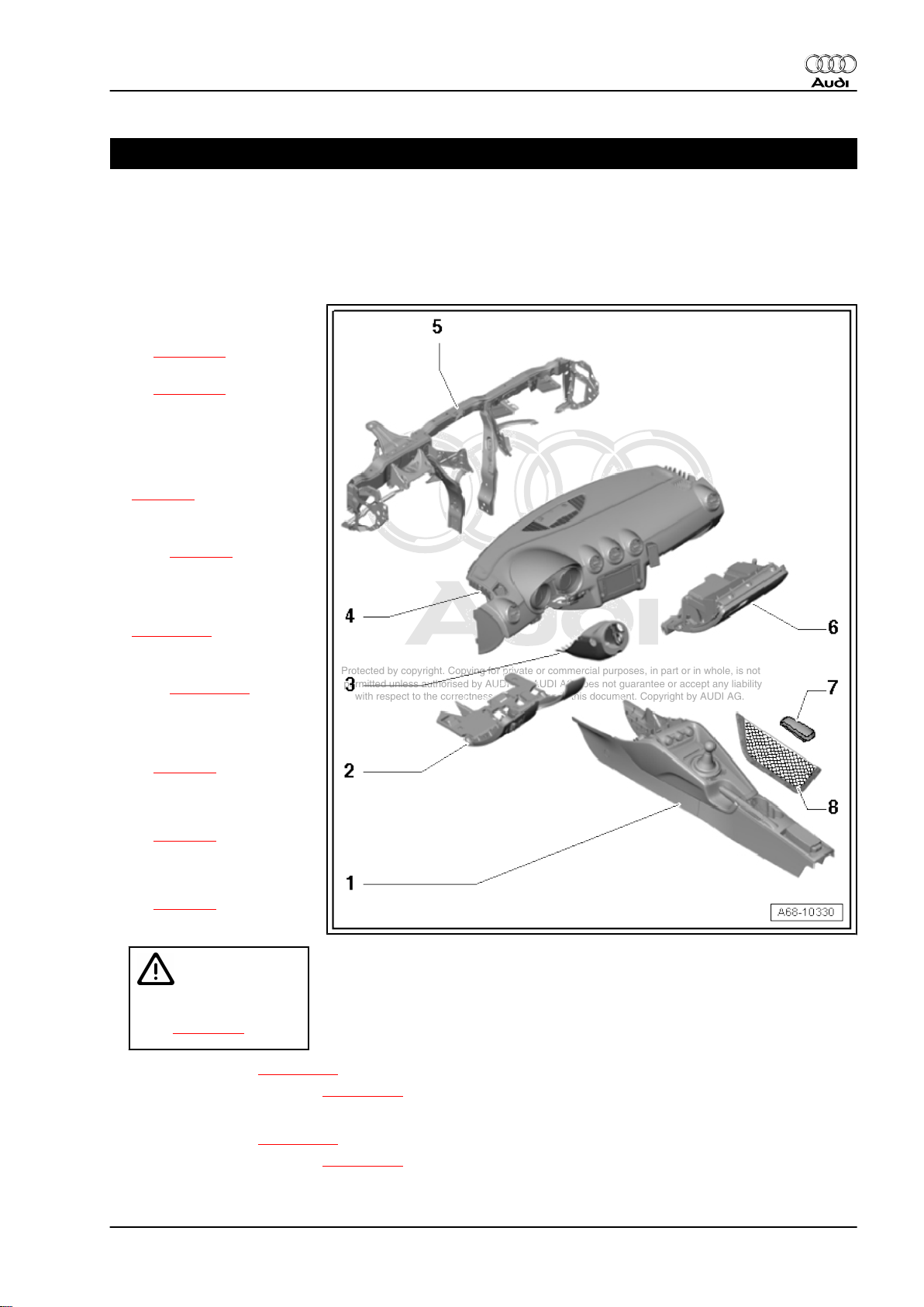
1 Shelves / trim panels
1.1 Exploded view of shelves / trim panels
1 - Centre console
❑ Exploded view
⇒ page 14
❑ Removing and installing
⇒ page 22
2 - Dash panel trim (driver side)
❑ Vehicles without knee
airbag:
♦ Exploded view
⇒ page 4
♦ Removing and installing
dash panel trim (driver
side) ⇒ page 5
❑ Vehicles with knee air‐
bag:
♦ Exploded view
⇒ page 102
♦ Removing and installing
dash panel trim (driver
side) ⇒ page 104
3 - Trim for steering column
switch
❑ Exploded view
⇒ page 6
❑ Removing and installing
upper trim for steering
column switch
⇒ page 7
❑ Removing and installing
trim (bottom) for steer‐
ing column switch
⇒ page 8
4 - Dash panel
Audi TT 2007 ➤
WARNING
Observe safety regula‐
tions for working on air‐
bags ⇒ page 42 .
❑ Exploded view ⇒ page 144
❑ Removing and installing ⇒ page 149
5 - Central tube
❑ Exploded view ⇒ page 153
❑ Removing and installing ⇒ page 156
1. Shelves / trim panels 3
Page 16
Protected by copyright. Copying for private or commercial purposes, in part or in whole, is not
permitted unless authorised by AUDI AG. AUDI AG does not guarantee or accept any liability
with respect to the correctness of information in this document. Copyright by AUDI AG.
Audi TT 2007 ➤
General body repairs, interior - Edition 07.2010
6 - Glove box
❑ Vehicles without knee airbag:
♦ Exploded view ⇒ page 9
♦ Removing and installing ⇒ page 12
❑ Vehicles with knee airbag:
♦ Exploded view ⇒ page 102
♦ Removing and installing ⇒ page 108
7 - Padding for centre armrest
❑ Exploded view ⇒ page 27
❑ Removing and installing ⇒ page 27
❑ Removing and installing holder for padding ⇒ page 28
8 - Storage net
❑ Depending on equipment version
❑ Attached to floor covering on passenger side in area of centre console
❑ Removing and installing ⇒ page 12
1.2 Exploded view of dash panel trim (driver side)
1 - Dash panel end trim
❑ Removing and installing
⇒ page 146
2 - Bolt
❑ 2.5 Nm
3 - 16-pin connector -T16-
❑ Diagnostic connector
4 - Spring clip
❑ For dash panel trim (bot‐
tom) on driver side
5 - Spring clip
❑ For upper dash panel
trim (driver side)
6 - Dash panel trim (driver side)
❑ Removing and installing
⇒ page 5
7 - Light switch
❑ Removing and installing
⇒ Rep. gr. 96
8 - Bolt
❑ 2.5 Nm
4 Rep. gr.68 - Interior equipment
Page 17
Protected by copyright. Copying for private or commercial purposes, in part or in whole, is not
permitted unless authorised by AUDI AG. AUDI AG does not guarantee or accept any liability
with respect to the correctness of information in this document. Copyright by AUDI AG.
General body repairs, interior - Edition 07.2010
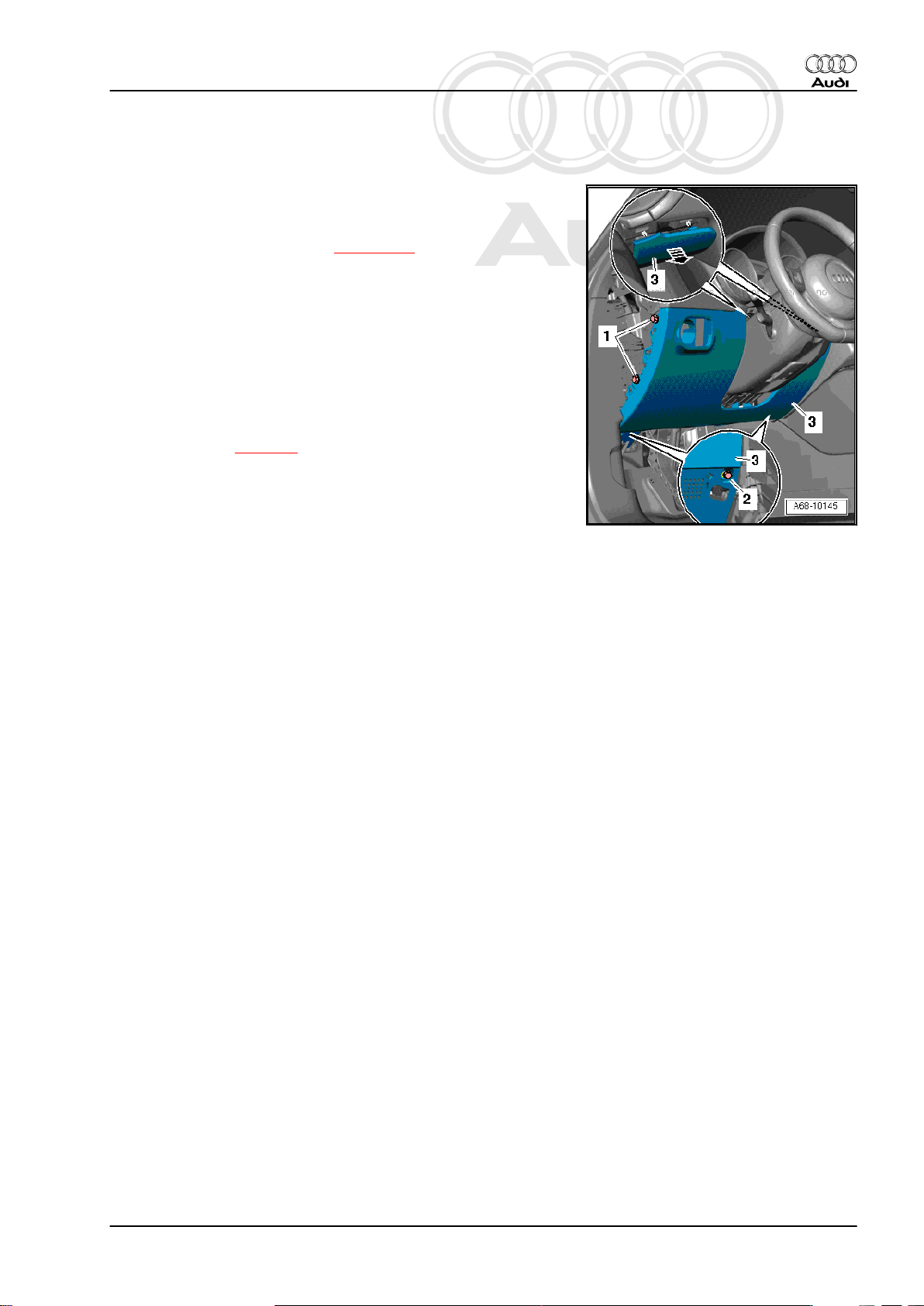
1.3 Removing and installing dash panel trim (driver side)
Removing
– Remove light switch ⇒ Rep. gr. 96 .
– Remove dash panel end trim ⇒ page 146 .
– Remove bolts -1- and -2-.
– Apply small screwdriver to top edge of dash panel trim (driver
side) -3- and unclip it from dash panel -arrow-.
– Unclip 16-pin connector -T16- .
– Detach dash panel trim (driver side).
Installing
Install in reverse order of removal.
Tightening torque ⇒ page 4
Audi TT 2007 ➤
1. Shelves / trim panels 5
Page 18
Protected by copyright. Copying for private or commercial purposes, in part or in whole, is not
permitted unless authorised by AUDI AG. AUDI AG does not guarantee or accept any liability
with respect to the correctness of information in this document. Copyright by AUDI AG.
Audi TT 2007 ➤
General body repairs, interior - Edition 07.2010
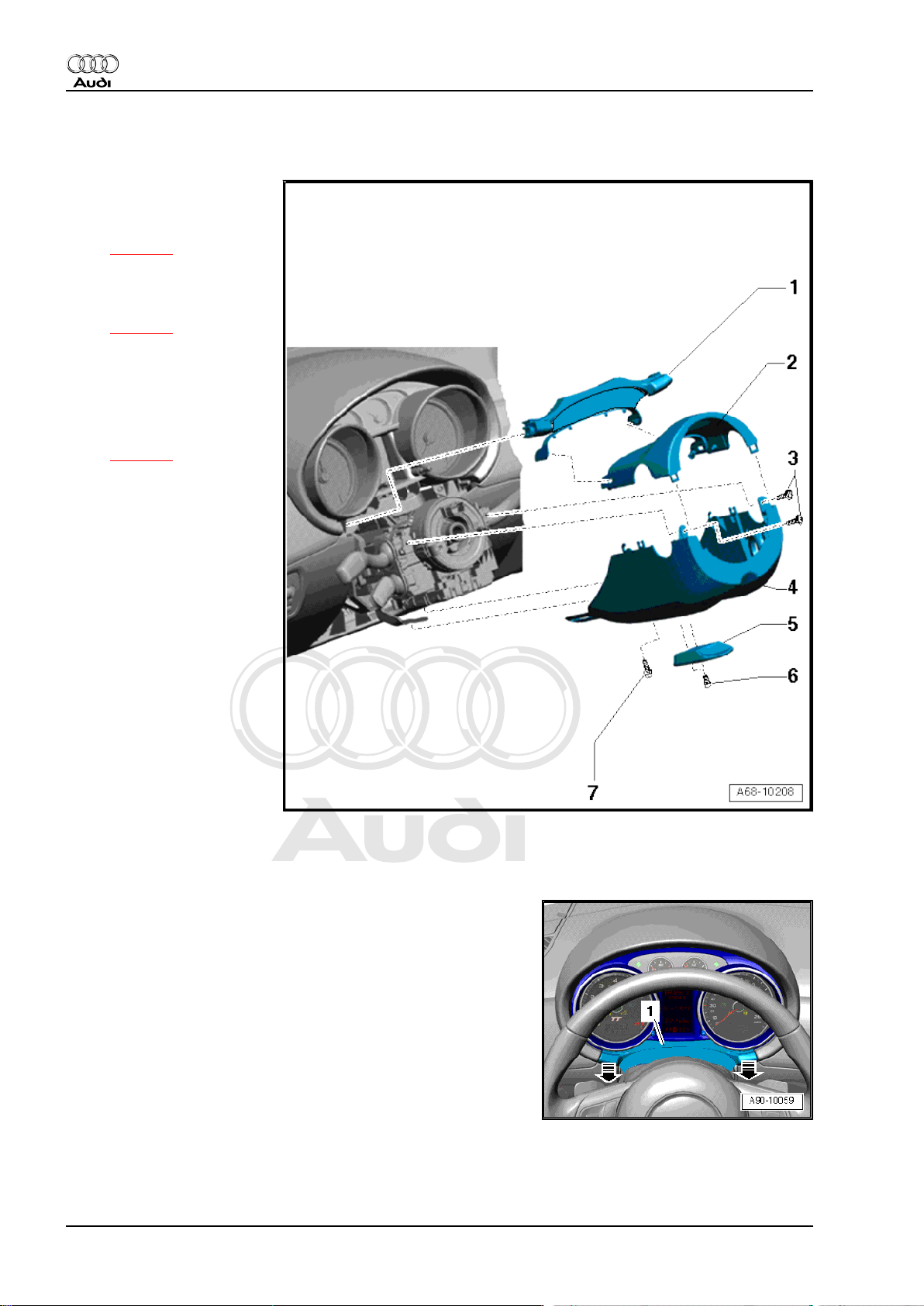
1.4 Exploded view of trim for steering column switch
1 - Trim cover
❑ For instrument cluster
❑ Removing and installing
⇒ page 6
2 - Trim (top) for steering col‐
umn switch
❑ Removing and installing
⇒ page 7
3 - Bolts
❑ 2.5 Nm
4 - Lower trim for steering col‐
umn switch
❑ Removing and installing
⇒ page 8
5 - Steering column adjust‐
ment handle
6 - Bolts
❑ 3 Nm
7 - Bolt
❑ 2.5 Nm
1.5 Removing and installing trim cover for instrument cluster
Removing
– Move steering wheel down and towards rear as far as it will
go, using full range of steering column adjuster.
– Pull off trim cover -1- in direction of -arrow-.
6 Rep. gr.68 - Interior equipment
Page 19
Protected by copyright. Copying for private or commercial purposes, in part or in whole, is not
permitted unless authorised by AUDI AG. AUDI AG does not guarantee or accept any liability
with respect to the correctness of information in this document. Copyright by AUDI AG.
General body repairs, interior - Edition 07.2010
– Use a small flat screwdriver to carefully prise trim cover -2- off
upper trim -3- for steering column switch.
Note
Disregard items -1- and -4-.
Installing
Installation is carried out in the reverse order; note the following:
– Make sure that trim cover engages audibly in trim (top).
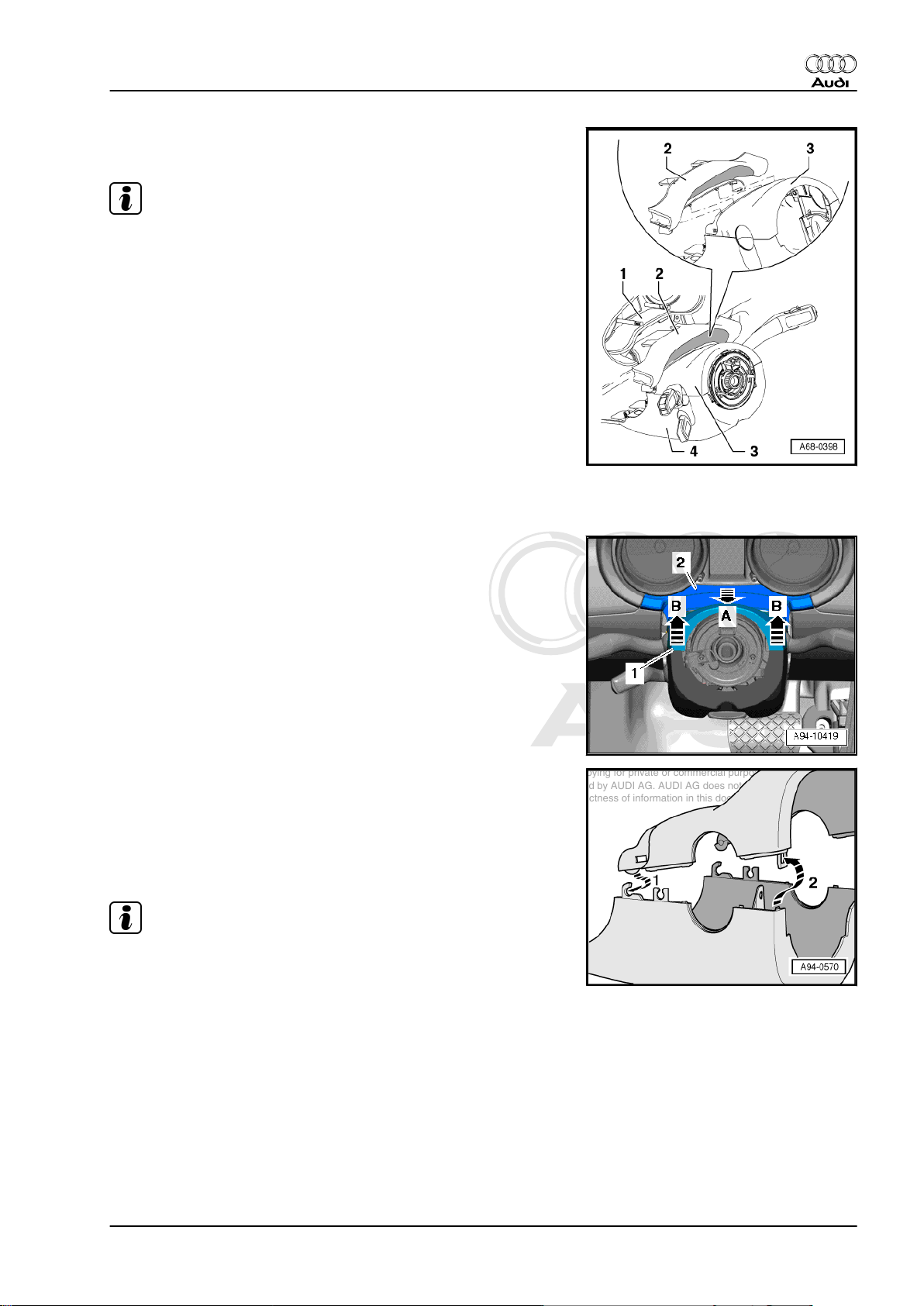
1.6 Removing and installing upper trim for steering column switch
Audi TT 2007 ➤
Removing
– Move steering wheel down and towards rear as far as it will
go, using full range of steering column adjuster.
– Detach trim cover -2- in direction of -arrow A-.
– Lift off upper trim -1- for steering column switch -arrows B-.
– Disengage upper trim for steering column switch at lower trim.
Installing
Installation is carried out in the reverse order; note the following:
– First engage upper trim in lower trim -arrow 1-.
– Make sure that lug of lower trim engages in recess at retaining
tab of upper trim -arrow 2-.
Note
Shown in the illustration with the steering column switch trim re‐
moved.
– Engage trim cover at instrument cluster.
1. Shelves / trim panels 7
Page 20
Protected by copyright. Copying for private or commercial purposes, in part or in whole, is not
permitted unless authorised by AUDI AG. AUDI AG does not guarantee or accept any liability
with respect to the correctness of information in this document. Copyright by AUDI AG.
Audi TT 2007 ➤
General body repairs, interior - Edition 07.2010
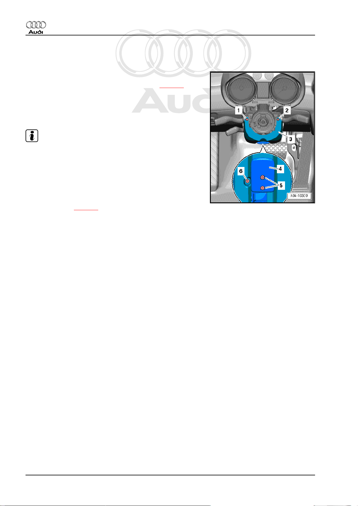
1.7 Removing and installing trim (bottom) for steering column switch
Removing
– Remove upper trim for steering column switch ⇒ page 7 .
– Unscrew bolts -5- and remove handle -4- for adjusting steering
column.
– Starting from straight ahead position, turn steering wheel 90°
and remove bolts -1- and -2-.
Note
If bolts -1- and -2- are not accessible, steering wheel must be
removed before performing remaining work steps ⇒ Rep. gr. 48 .
– Remove bolt -6- and detach lower trim -3- for steering column
switch.
Installing
Install in reverse order of removal.
Tightening torque ⇒ page 6
8 Rep. gr.68 - Interior equipment
Page 21
Protected by copyright. Copying for private or commercial purposes, in part or in whole, is not
permitted unless authorised by AUDI AG. AUDI AG does not guarantee or accept any liability
with respect to the correctness of information in this document. Copyright by AUDI AG.
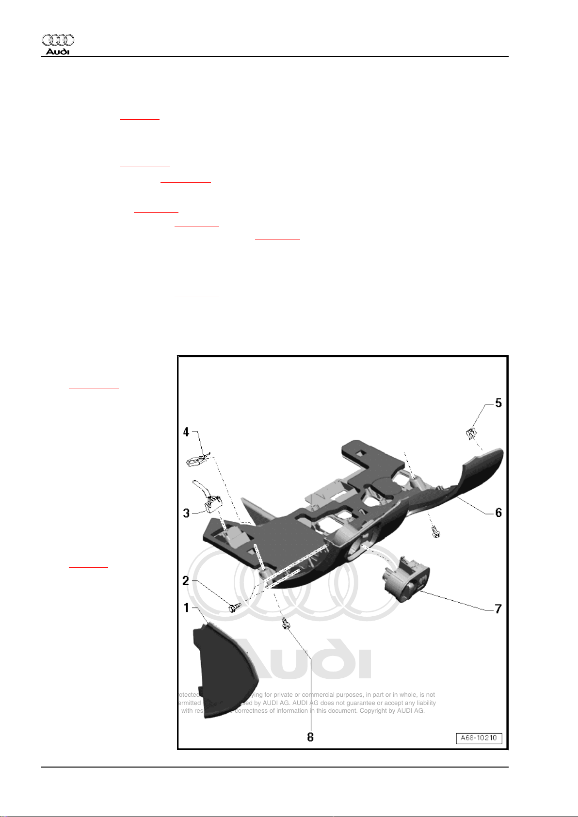
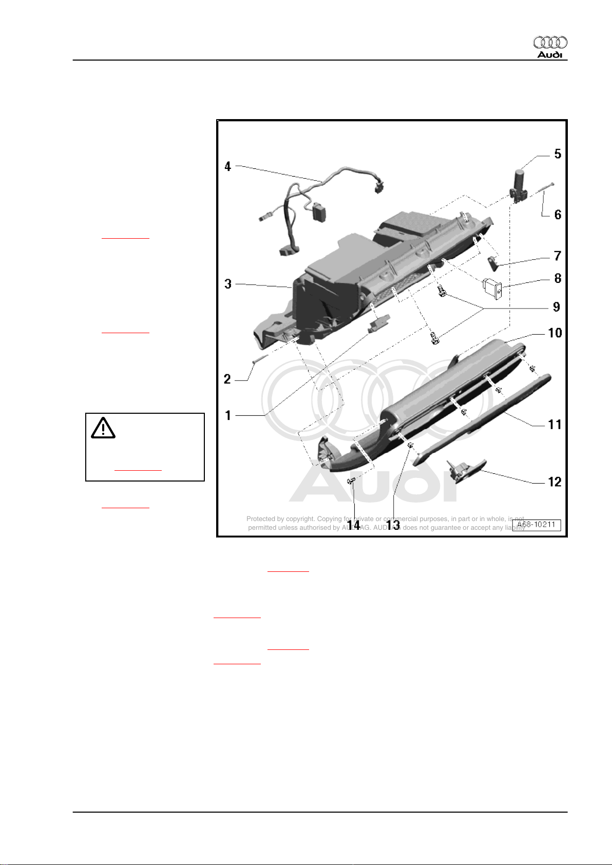
1.8 Exploded view of glove box
1 - Glove box light
❑ Removing and installing
⇒ Rep. gr. 96
2 - Hinge pin
❑ For securing glove box
lid
3 - Glove box
❑ Removing and installing
⇒ page 12
4 - Wiring harness for glove
box
5 - Cushioning element
❑ With glove box light
switch -E26-
❑ Removing and installing
⇒ page 12
6 - Hinge pin
7 - Mounting for striker pin
8 - Key-operated switch to de‐
activate airbag on front pas‐
senger side -E224-
Audi TT 2007 ➤
General body repairs, interior - Edition 07.2010
WARNING
Observe safety regula‐
tions for working on air‐
bags ⇒ page 42 .
❑ Removing and installing
⇒ page 97
9 - Bolt
❑ 2.5 Nm
10 - Glove box lid
❑ Manually releasing the glove box lid ⇒ page 9
❑ Cannot be renewed as a separate unit
11 - Trim panel for glove box lid
❑ Removing and installing ⇒ page 10
12 - Glove box opening mechanism with lock
❑ Manually releasing the glove box lid ⇒ page 9
❑ Removing and installing ⇒ page 11
13 - Clip
14 - Bolt
❑ 1.6 Nm
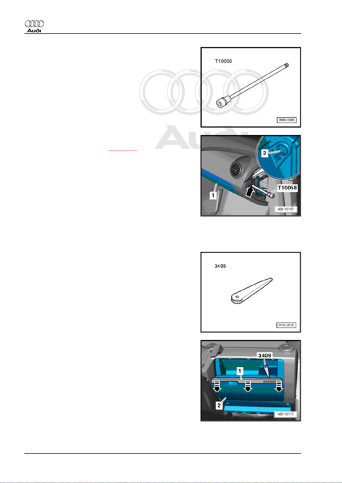
1.9 Manually releasing the glove box lid
Special tools and workshop equipment required
1. Shelves / trim panels 9
Page 22
Protected by copyright. Copying for private or commercial purposes, in part or in whole, is not
permitted unless authorised by AUDI AG. AUDI AG does not guarantee or accept any liability
with respect to the correctness of information in this document. Copyright by AUDI AG.
Audi TT 2007 ➤
General body repairs, interior - Edition 07.2010
♦ Allen key, long reach -T10058-
Procedure
– Remove dash panel end trim ⇒ page 146 .
– Insert Allen key -T10058- (or similar suitable tool with a length
of 115 mm) through opening -arrow- in dash panel (passenger
side).
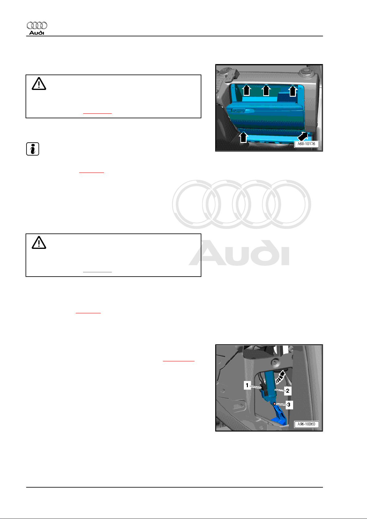
– Open glove box lid -1- by pressing down locking pin -2-.
1.10 Removing and installing trim panel for glove box lid
Special tools and workshop equipment required
♦ Removal wedge -3409-
Removing
– Open glove box.
– Use removal wedge -3409- to carefully unclip trim panel -1-
from glove box lid -2- -arrows-.
Installing
Installation is carried out in the reverse order; note the following:
– Make sure trim panel engages audibly.
10 Rep. gr.68 - Interior equipment
Page 23
Protected by copyright. Copying for private or commercial purposes, in part or in whole, is not
permitted unless authorised by AUDI AG. AUDI AG does not guarantee or accept any liability
with respect to the correctness of information in this document. Copyright by AUDI AG.
General body repairs, interior - Edition 07.2010
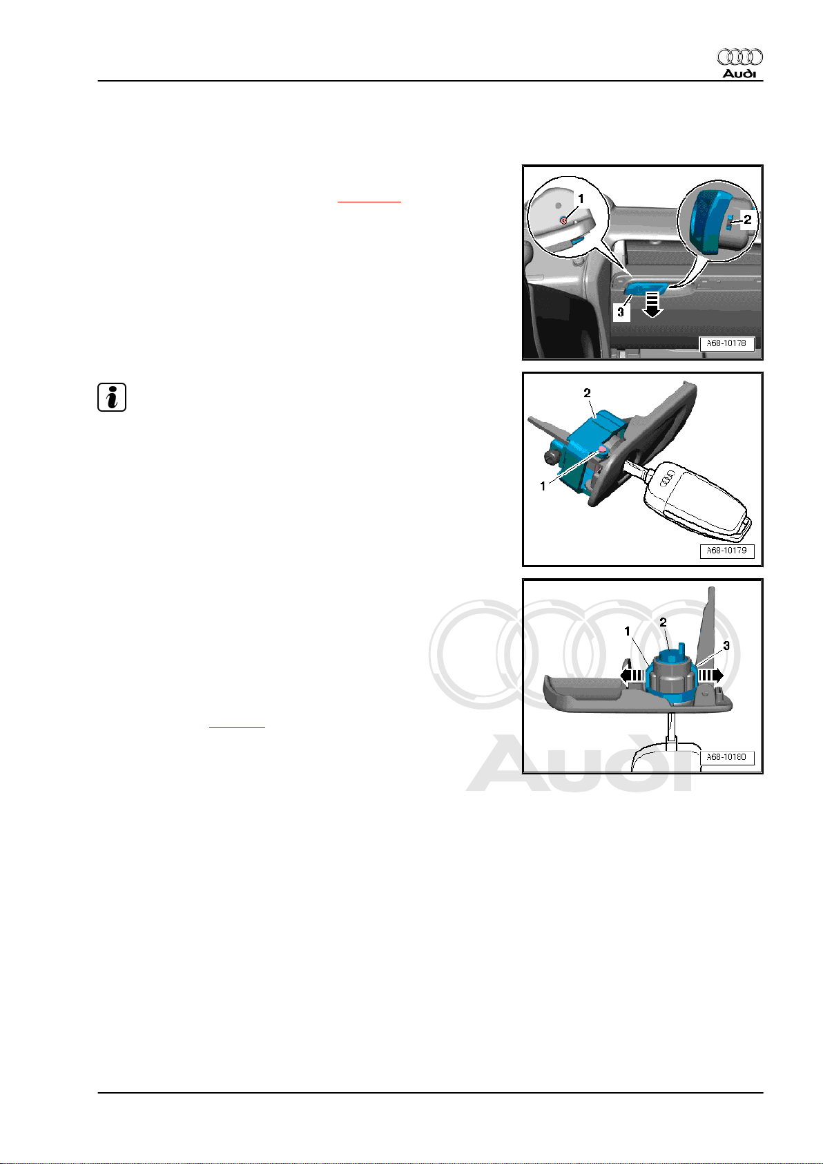
1.11 Removing and installing glove box opening mechanism with lock
Removing
– Remove trim panel for glove box lid ⇒ page 10 .
– Remove bolt -1-.
– Use a screwdriver to press down catch -2- on side of glove box
opening mechanism.
– Take out glove box opening mechanism -3- with lock -arrow-.
Note
The lock cylinder can only be removed with the key inserted.
Audi TT 2007 ➤
– Use a drift punch to knock out pin -1-.
– Detach cap -2-.
– Use screwdriver to carefully prise retainers -1- and -3- in di‐
rection of -arrow- and at the same time pull lock cylinder -2out of glove box opening mechanism.
Installing
Installation is carried out in the reverse order; note the following:
– With key inserted, press in lock cylinder until it engages audi‐
bly in all retainers.
Tightening torque ⇒ page 9
1. Shelves / trim panels 11
Page 24
Protected by copyright. Copying for private or commercial purposes, in part or in whole, is not
permitted unless authorised by AUDI AG. AUDI AG does not guarantee or accept any liability
with respect to the correctness of information in this document. Copyright by AUDI AG.
Audi TT 2007 ➤
General body repairs, interior - Edition 07.2010
1.12 Removing and installing glove box
Removing
WARNING
On vehicles with key-operated switch to deactivate airbag on
front passenger side -E224- , observe safety regulations for
working on airbags ⇒ page 42 .
– Open glove box lid.
Note
If the glove box lid cannot be opened in the normal way, you can
release it manually ⇒ page 9 .
– If fitted, remove CD changer ⇒ Rep. gr. 91 .
– Unscrew bolts -arrows- and detach glove box.
All vehicles:
– Unplug electrical connector at main connector.
Installing
WARNING
On vehicles with key-operated switch to deactivate airbag on
front passenger side -E224- , observe safety regulations for
working on airbags ⇒ page 42 .
Installation is carried out in the reverse order; note the following:
– Make sure connectors engage audibly.
Tightening torque ⇒ page 9
1.13 Removing and installing cushioning el‐
ement for glove box lid
Removing
– Remove dash panel end trim (passenger side) ⇒ page 146 .
– If fitted, remove aerial amplifier for mobile telephone -R86- ⇒
Rep. gr. 91 .
– Unplug electrical connector -1-.
– Pull out hinge pin -3-.
– Release cushioning element -2- in anti-clockwise direction
-arrow- and detach.
Installing
Install in reverse order of removal.
1.14 Removing and installing storage net
Removing
– Remove front passenger's seat:
12 Rep. gr.68 - Interior equipment
Page 25
Protected by copyright. Copying for private or commercial purposes, in part or in whole, is not
permitted unless authorised by AUDI AG. AUDI AG does not guarantee or accept any liability
with respect to the correctness of information in this document. Copyright by AUDI AG.
General body repairs, interior - Edition 07.2010
♦ Removing and installing front seats (with manual adjustment)
⇒ page 243
♦ Removing and installing front seats (with electric adjustment)
⇒ page 274
– Remove centre console side trim (passenger side)
⇒ page 17 .
– Disengage floor covering from bracket at tunnel.
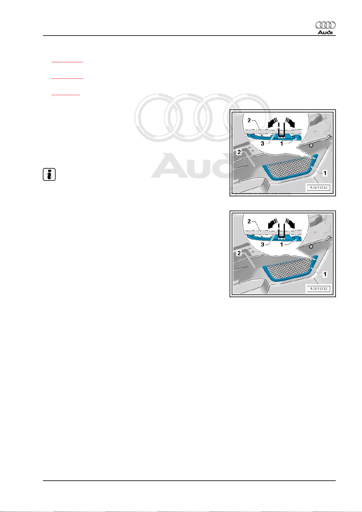
– Fold over floor covering -2- in area of front passenger's foot‐
well.
– Bend back clips -3- securing storage net -1- (on back of floor
covering -2-) by 90° (in opposite direction of -arrows-).
– Detach net from floor covering.
Installing
Note
When installing a new floor covering, make perforations for the
storage net where they were made in the old floor covering.
Audi TT 2007 ➤
– Insert net -1- into perforations in floor covering -2-.
– Bend back clips -3- on back of floor covering in direction of
-arrows- until they touch the covering. To do so, hold the net
from the front.
Perform remaining installation in reverse order of removal.
1. Shelves / trim panels 13
Page 26
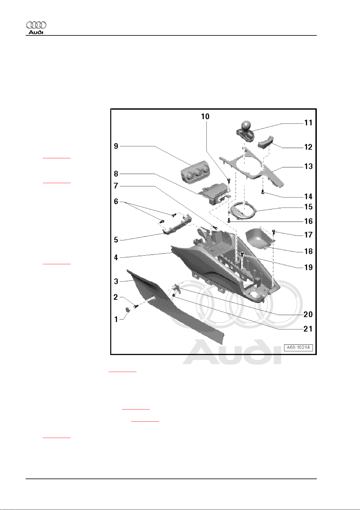
Protected by copyright. Copying for private or commercial purposes, in part or in whole, is not
permitted unless authorised by AUDI AG. AUDI AG does not guarantee or accept any liability
with respect to the correctness of information in this document. Copyright by AUDI AG.
Audi TT 2007 ➤
General body repairs, interior - Edition 07.2010
2 Centre console
2.1 Exploded view of centre console
Part 1 (front)
1 - Cap
2 - Bolt
❑ 2.5 Nm
3 - Centre console side trim
❑ Removing and installing
⇒ page 17
4 - Centre console (front)
❑ Removing and installing
⇒ page 22
5 - Bracket for centre console
❑ With adjuster
6 - Bolt
❑ 3.5 Nm
7 - Bolt
❑ 3.5 Nm
8 - Ashtray
❑ Removing and installing
⇒ page 21
9 - Climatronic control unit J255-
❑ Removing and installing
⇒ Rep. gr. 87
10 - Bolt
❑ 2.5 Nm
11 - Selector lever/gear lever
❑ Removing and installing
selector lever/gear lever
⇒ Rep. gr. 34
12 - Button module
❑ In centre console trim
❑ Removing and installing ⇒ page 20
13 - Centre console trim
❑ Different versions
❑ Removing and installing:
Vehicles with manual gearbox ⇒ page 17
Vehicles with dual clutch gearbox ⇒ page 18
❑ Installation position of convertible roof actuation button -E137- and cabrio windbreak switch -E278-
⇒ page 20
14 - Bolt
❑ 1 Nm
14 Rep. gr.68 - Interior equipment
Page 27

Protected by copyright. Copying for private or commercial purposes, in part or in whole, is not
permitted unless authorised by AUDI AG. AUDI AG does not guarantee or accept any liability
with respect to the correctness of information in this document. Copyright by AUDI AG.
15 - Trim frame
❑ Different versions
❑ Removing and installing:
Vehicles with manual gearbox ⇒ page 19
Vehicles with dual clutch gearbox ⇒ page 20
16 - Bolt
❑ 1 Nm
17 - Bolt
❑ 2.5 Nm
18 - Grip moulding for handbrake lever
❑ Removing and installing ⇒ page 21
19 - Bolt
❑ 3.5 Nm
20 - Bracket for side trim
❑ Removing and installing ⇒ page 17
21 - Nut
❑ 3.5 Nm
Audi TT 2007 ➤
General body repairs, interior - Edition 07.2010
Part 2 (rear)
2. Centre console 15
Page 28
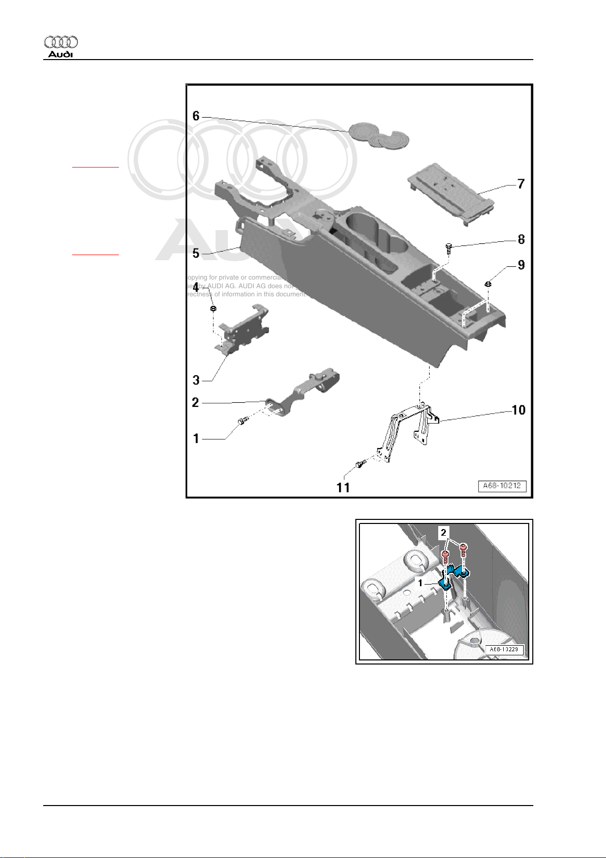
Protected by copyright. Copying for private or commercial purposes, in part or in whole, is not
permitted unless authorised by AUDI AG. AUDI AG does not guarantee or accept any liability
with respect to the correctness of information in this document. Copyright by AUDI AG.
Audi TT 2007 ➤
General body repairs, interior - Edition 07.2010
1 - Bolt
❑ 3.5 Nm
2 - Retainer
3 - Bracket for centre console
❑ Removing and installing
⇒ page 24
4 - Nut
❑ 8 Nm
5 - Centre console (rear)
❑ Different versions
❑ Removing and installing
⇒ page 23
6 - Lining mat
7 - Telephone bracket -R126- /
storage compartment
❑ Removing and installing
telephone bracket R126- ⇒ Rep. gr. 91
8 - Bolt
❑ 2.5 Nm
❑ For Roadster only
9 - Nut
❑ 3.5 Nm
10 - Bracket for centre console
❑ For Roadster only
11 - Bolt
❑ 3.5 Nm
❑ For Roadster only
Tightening torque for dummy cover for AUX socket
1 - Dummy cover for AUX socket
2 - Bolts, 1.5 Nm
16 Rep. gr.68 - Interior equipment
Page 29
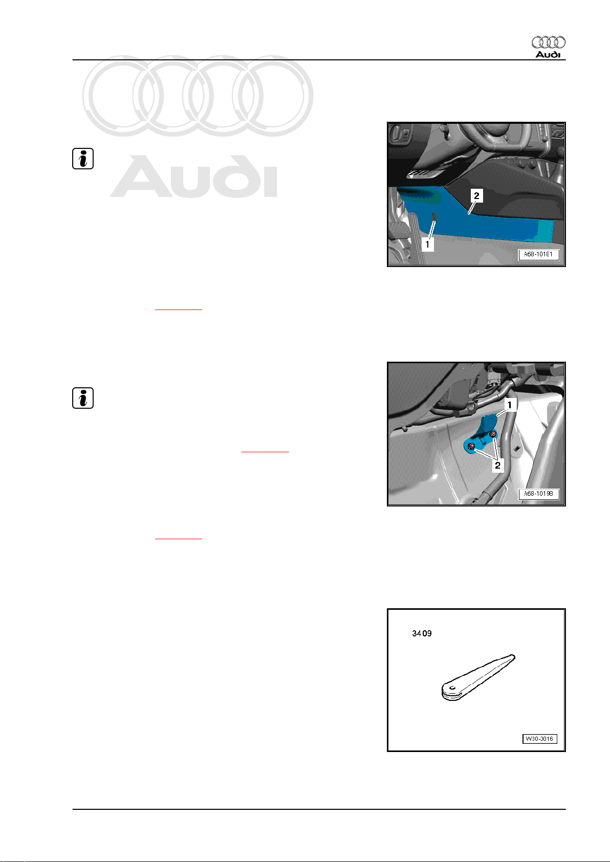
Protected by copyright. Copying for private or commercial purposes, in part or in whole, is not
permitted unless authorised by AUDI AG. AUDI AG does not guarantee or accept any liability
with respect to the correctness of information in this document. Copyright by AUDI AG.
General body repairs, interior - Edition 07.2010
2.2 Removing and installing side trim for centre console
Removing
Note
Removal and installation are identical on the left and right.
– Use a screwdriver to prise off cap -1- and unscrew bolt.
– Reach beneath the side trim -2- and carefully detach it from
the centre console.
Installing
Installation is carried out in the reverse order; note the following:
– Make sure side trim engages audibly.
Tightening torque ⇒ page 14
2.3 Removing and installing bracket for side trim
Audi TT 2007 ➤
Removing
Note
Removal and installation are identical on the left and right.
– Remove centre console side trim ⇒ page 17 .
– Fold back floor covering in area of bracket -1-.
– Unscrew nuts -2- and detach bracket from centre tunnel.
Installing
Install in reverse order of removal.
Tightening torque ⇒ page 14
2.4 Removing and installing centre console trim - vehicles with manual gearbox
Special tools and workshop equipment required
♦ Removal wedge -3409-
2. Centre console 17
Page 30
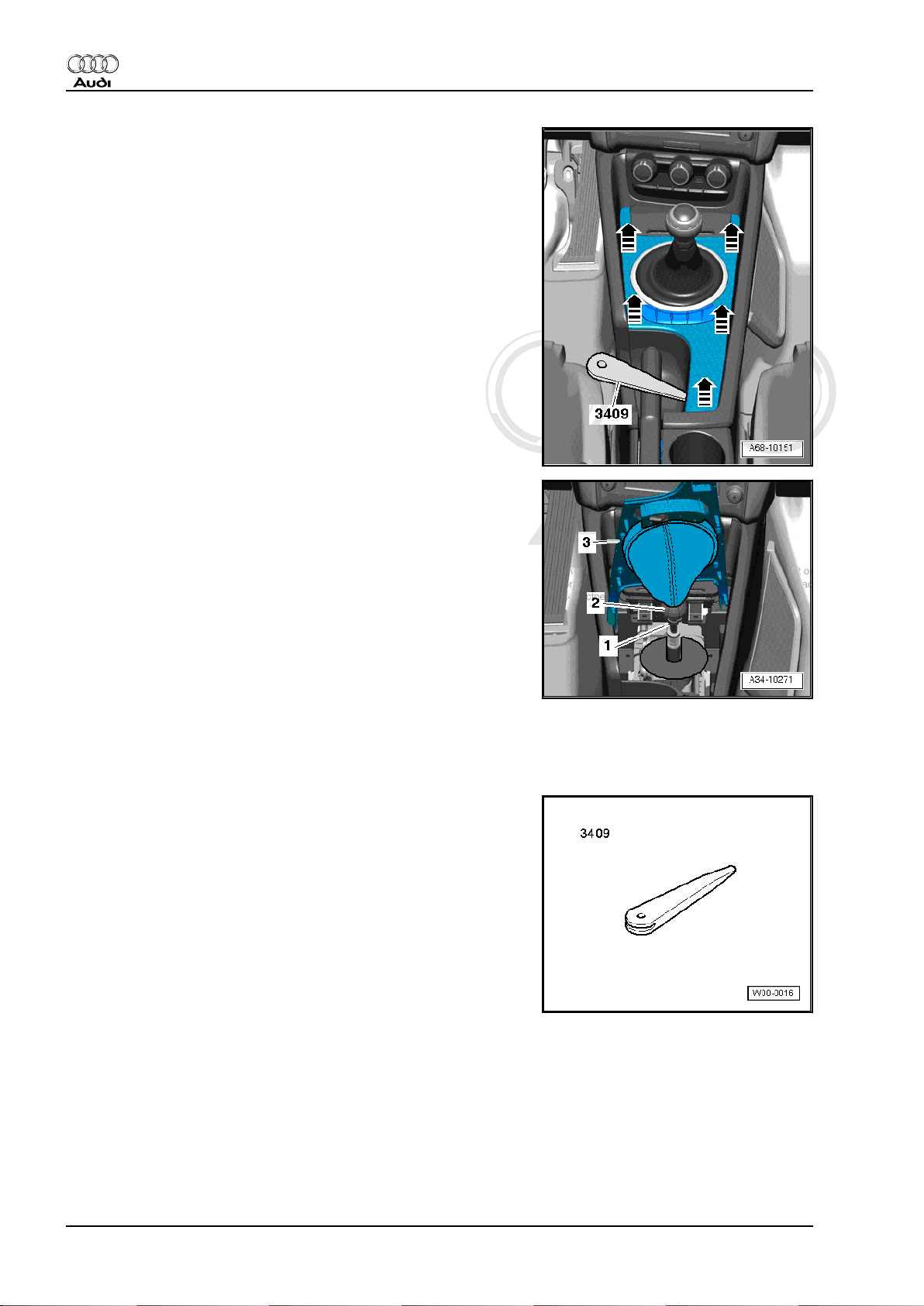
Protected by copyright. Copying for private or commercial purposes, in part or in whole, is not
permitted unless authorised by AUDI AG. AUDI AG does not guarantee or accept any liability
with respect to the correctness of information in this document. Copyright by AUDI AG.
Audi TT 2007 ➤
General body repairs, interior - Edition 07.2010
Removing
– Use removal wedge -3409- to prise centre console trim out of
centre console -arrows-.
– Unplug electrical connectors.
– Fold centre console trim together with gear lever boot upwards
over gear knob.
– Unfasten hose clamp -1- and lift off gear knob -2- together with
centre console trim -3-.
Installing
Installation is carried out in the reverse order; note the following:
– Make sure trim engages audibly in centre console.
2.5 Removing and installing centre console trim - vehicles with dual clutch gearbox
Special tools and workshop equipment required
♦ Removal wedge -3409-
18 Rep. gr.68 - Interior equipment
Page 31

Protected by copyright. Copying for private or commercial purposes, in part or in whole, is not
permitted unless authorised by AUDI AG. AUDI AG does not guarantee or accept any liability
with respect to the correctness of information in this document. Copyright by AUDI AG.
General body repairs, interior - Edition 07.2010
Removing
– Use a small screwdriver to carefully prise out the selector lever
boot at the side -arrow 1-.
– Lift off the selector lever boot on both sides -arrows 2 and 3-.
– Use removal wedge -3409- to prise centre console trim out of
centre console -arrows-.
– Unplug electrical connectors.
Installing
Installation is carried out in the reverse order; note the following:
– Make sure trim engages audibly in centre console.
Audi TT 2007 ➤
2.6 Removing and installing trim frame - ve‐
hicles with manual gearbox
Removing
– Remove centre console trim ⇒ page 17 .
– Release gear lever boot -arrows- and detach it from trim frame
together with gear knob -5-.
– Remove bolts -1, 3, 4, 6- and detach trim frame -2-.
Installing
Install in reverse order of removal.
Tightening torque ⇒ page 14
2. Centre console 19
Page 32

Protected by copyright. Copying for private or commercial purposes, in part or in whole, is not
permitted unless authorised by AUDI AG. AUDI AG does not guarantee or accept any liability
with respect to the correctness of information in this document. Copyright by AUDI AG.
Audi TT 2007 ➤
General body repairs, interior - Edition 07.2010
2.7 Removing and installing trim frame - ve‐
hicles with dual clutch gearbox
Removing
– Remove centre console trim ⇒ page 18 .
– Unscrew bolts -arrows- and detach trim frame -1- with selector
lever position display -Y26- .
Installing
Install in reverse order of removal.
Tightening torque ⇒ page 14
2.8 Removing and installing button module in centre console trim
Removing
Note
The illustration shows a vehicle with dual clutch gearbox.
– Remove centre console trim: vehicles with manual gearbox
⇒ page 17 , vehicles with dual clutch gearbox ⇒ page 18 .
– Remove bolts -arrows- and detach button module -1-.
Installing
Install in reverse order of removal.
Tightening torque ⇒ page 14
2.9 Installation position of convertible roof actuation button -E137- and cabrio windbreak switch -E278-
1 - Convertible roof actuation button -E137-
2 - Cabrio windbreak switch -E278-
3 - Centre console trim
Note
Removing and installing convertible roof actuation button -E137and cabrio windbreak switch -E278- ⇒ Electrical System; Rep.
gr. 96
20 Rep. gr.68 - Interior equipment
Page 33

Protected by copyright. Copying for private or commercial purposes, in part or in whole, is not
permitted unless authorised by AUDI AG. AUDI AG does not guarantee or accept any liability
with respect to the correctness of information in this document. Copyright by AUDI AG.
General body repairs, interior - Edition 07.2010
2.10 Removing and installing grip moulding for handbrake lever
Removing
– Remove centre console trim: vehicles with manual gearbox
⇒ page 17 , vehicles with dual clutch gearbox ⇒ page 18 .
– Apply handbrake.
– Remove bolts -1- and -2-.
– Lift the grip moulding for the handbrake lever -3- at the front
-arrow- and remove it to the front out of the centre console.
Installing
Installation is carried out in the reverse order; note the following:
– Make sure the grip moulding for the handbrake lever is prop‐
erly inserted in the spring clip.
Tightening torque ⇒ page 14
2.11 Removing and installing ashtray
Audi TT 2007 ➤
Removing
– Remove Climatronic control unit -J255- ⇒ Rep. gr. 87 .
– Remove centre console trim: vehicles with manual gearbox
⇒ page 17 , vehicles with dual clutch gearbox ⇒ page 18 .
– Unscrew bolts -arrows- and carefully take out ashtray -1- to‐
wards rear.
– Unplug cigarette lighter connector at ashtray.
Installing
Install in reverse order of removal.
Tightening torque ⇒ page 14
2.12 Removing and installing ashtray lid
Removing
– Remove ashtray ⇒ page 21 .
– Press down retaining tabs -1- and -3- (left and right) and slide
lid -2- off ashtray -arrow-.
Installing
Install in reverse order of removal.
2. Centre console 21
Page 34

Protected by copyright. Copying for private or commercial purposes, in part or in whole, is not
permitted unless authorised by AUDI AG. AUDI AG does not guarantee or accept any liability
with respect to the correctness of information in this document. Copyright by AUDI AG.
Audi TT 2007 ➤
General body repairs, interior - Edition 07.2010
2.13 Removing and installing trim for ashtray lid
Removing
– Remove ashtray ⇒ page 21 .
– Use a screwdriver to carefully prise trim -1- off ashtray lid
-arrows- (left and right).
Installing
Installation is carried out in the reverse order; note the following:
– Make sure trim for ashtray lid engages audibly.
2.14 Removing and installing centre console (front)
Removing
– Remove centre console side trim panels ⇒ page 17 .
– Remove centre console trim: vehicles with manual gearbox
⇒ page 17 , vehicles with dual clutch gearbox ⇒ page 18 .
– Remove grip moulding for handbrake lever ⇒ page 21 .
– Remove ashtray ⇒ page 21 .
– Unscrew bolts -1 ... 10-.
Note
The illustration shows a vehicle with dual clutch gearbox.
– Apply handbrake as firmly as possible.
– Pull the rear centre console upwards -arrow A- and guide it
past the handbrake lever. To do so, slide the centre console
forwards as far as possible -arrow B-.
– Remove centre console to the rear over selector lever or gear
lever.
22 Rep. gr.68 - Interior equipment
Page 35

Protected by copyright. Copying for private or commercial purposes, in part or in whole, is not
permitted unless authorised by AUDI AG. AUDI AG does not guarantee or accept any liability
with respect to the correctness of information in this document. Copyright by AUDI AG.
General body repairs, interior - Edition 07.2010
Installing
Installation is carried out in the reverse order; note the following:
– Check freedom of movement of adjuster nut -1- of adjuster
-arrows-.
– Screw in adjuster nuts as far as they will go, but do not tighten.
Note
When tightening the bolts, the nuts of the adjusters automatically
turn towards the mounting points of the centre console to lock it
in place.
Tightening torque ⇒ page 14
2.15 Removing and installing centre console (rear)
Special tools and workshop equipment required
♦ Removal lever -80 - 200-
Audi TT 2007 ➤
♦ Hook -3438-
Removing
– Remove centre console (front) ⇒ page 22 .
– If fitted, remove holder for padding ⇒ page 28 .
– If fitted, remove telephone bracket -R126- ⇒ Rep. gr. 91 .
– Take out lining mat.
– Pull the storage compartment -1- with the hook -3438- out of
the centre console -arrows-.
– Unplug electrical connector from AUX socket.
2. Centre console 23
Page 36

Protected by copyright. Copying for private or commercial purposes, in part or in whole, is not
permitted unless authorised by AUDI AG. AUDI AG does not guarantee or accept any liability
with respect to the correctness of information in this document. Copyright by AUDI AG.
Audi TT 2007 ➤
General body repairs, interior - Edition 07.2010
– Press clip -arrow- off centre console using removal lever -80 -
200- .
Note
Use silicone-free lubricant spray to facilitate removal of the clip if
necessary.
– Unscrew nuts -1- and -3-.
– Pull centre console -2- upwards and guide it out over hand‐
brake lever.
Installing
Install in reverse order of removal.
Tightening torque ⇒ page 15
2.16 Removing and installing brackets for centre console
Special tools and workshop equipment required
♦ Removal lever -80 - 200-
Removing
– Remove centre console (rear) ⇒ page 22 .
– Press clips -arrows- off bracket using removal lever -80 - 200- .
Note
Use silicone-free lubricant spray to facilitate removal of the clips
if necessary.
– Unscrew nuts -1- and -2- and detach bracket.
Installing
Install in reverse order of removal.
Tightening torque ⇒ page 15
24 Rep. gr.68 - Interior equipment
Page 37

Protected by copyright. Copying for private or commercial purposes, in part or in whole, is not
permitted unless authorised by AUDI AG. AUDI AG does not guarantee or accept any liability
with respect to the correctness of information in this document. Copyright by AUDI AG.
General body repairs, interior - Edition 07.2010
3 Trim for handbrake grip
3.1 Exploded view of trim for handbrake grip
1 - Trim for handbrake grip
❑ For vehicles with no
centre armrest
❑ Removing and installing
⇒ page 26
2 - Stud
❑ Detach after removing
trim for handbrake grip
3 - Handbrake trim (left-side)
❑ For vehicles with centre
armrest
❑ Removing and installing
⇒ page 26
4 - Trim for handbrake grip
❑ For vehicles with centre
armrest
❑ Removing and installing
⇒ page 26
5 - Pushbutton
❑ Detach after removing
trim for handbrake grip
6 - Cap
❑ For vehicles with centre
armrest
7 - Bolt
❑ For vehicles with centre
armrest
❑ 2.5 Nm
❑ 3x
8 - Handbrake trim (right-side)
❑ For vehicles with centre
armrest
❑ Removing and installing ⇒ page 26
Audi TT 2007 ➤
3. Trim for handbrake grip 25
Page 38

Protected by copyright. Copying for private or commercial purposes, in part or in whole, is not
permitted unless authorised by AUDI AG. AUDI AG does not guarantee or accept any liability
with respect to the correctness of information in this document. Copyright by AUDI AG.
Audi TT 2007 ➤
General body repairs, interior - Edition 07.2010
3.2 Removing and installing trim for hand‐
brake grip - vehicles with no centre arm‐
rest
Removing
– Apply handbrake as firmly as possible.
– Release retaining clip through recess at bottom of handbrake
grip using a small screwdriver -2-.
– Detach trim for handbrake grip -1- to the front -arrow-.
Installing
Installation is carried out in the reverse order; note the following:
– Make sure trim for handbrake grip engages audibly.
3.3 Removing and installing trim for hand‐
brake grip - vehicles with centre armrest
Removing
– Remove holder for padding ⇒ page 28 .
– Apply handbrake as firmly as possible.
– Use a small screwdriver -2- to pierce seam of handbrake grip
at position shown in illustration.
– Release retaining clip beneath it and detach trim for hand‐
brake grip -1- to the front -arrow-.
Installing
Installation is carried out in the reverse order; note the following:
– Make sure trim for handbrake grip engages audibly.
3.4 Removing and installing handbrake trim panels (left and right) - vehicles with centre armrest
Removing
– Remove centre console (rear) ⇒ page 23 .
– Remove trim for handbrake grip ⇒ page 26 .
– Unscrew bolts -4-.
– Use a screwdriver to prise off cap -1- and unscrew bolt.
– Detach trim panels -2 and 3- for handbrake lever.
Installing
Installation is carried out in the reverse order, note the following.
Tightening torque ⇒ page 25
26 Rep. gr.68 - Interior equipment
Page 39

Protected by copyright. Copying for private or commercial purposes, in part or in whole, is not
permitted unless authorised by AUDI AG. AUDI AG does not guarantee or accept any liability
with respect to the correctness of information in this document. Copyright by AUDI AG.
General body repairs, interior - Edition 07.2010
4 Centre armrest
4.1 Exploded view of centre armrest
1 - Trim for handbrake lever
2 - Retaining spring
3 - Padding for centre armrest
❑ Removing and installing
⇒ page 27
❑ Cannot be dismantled
4 - Bolt
❑ 2.5 Nm
❑ 3x
5 - Holder for padding
❑ Removing and installing
⇒ page 28
Audi TT 2007 ➤
4.2 Removing and installing centre armrest padding
Removing
– Lift the centre armrest padding -1- out of the spring clips
-arrows-.
Installing
Installation is carried out in the reverse order; note the following:
– Make sure centre armrest padding engages audibly in spring
clips.
4. Centre armrest 27
Page 40

Protected by copyright. Copying for private or commercial purposes, in part or in whole, is not
permitted unless authorised by AUDI AG. AUDI AG does not guarantee or accept any liability
with respect to the correctness of information in this document. Copyright by AUDI AG.
Audi TT 2007 ➤
General body repairs, interior - Edition 07.2010
4.3 Removing and installing holder for pad‐
ding
Removing
– Remove centre armrest padding ⇒ page 27 .
– Remove bolts -arrows- and detach holder -1-.
Installing
Install in reverse order of removal.
Tightening torque ⇒ page 27
28 Rep. gr.68 - Interior equipment
Page 41

Protected by copyright. Copying for private or commercial purposes, in part or in whole, is not
permitted unless authorised by AUDI AG. AUDI AG does not guarantee or accept any liability
with respect to the correctness of information in this document. Copyright by AUDI AG.
General body repairs, interior - Edition 07.2010
5 Interior mirror
5.1 Safety regulations for interior mirror
WARNING
♦ The interior mirror glass consists of several layers and
contains an electrolyte which gives the mirror its proper‐
ties. Beware of liquid electrolyte escaping from a broken
mirror.
♦ Liquid electrolyte can cause irritation to skin, eyes and
respiratory organs.
♦ Should liquid electrolyte make contact with your skin or
eyes rinse it off immediately with lots of water. If the irri‐
tation does not go away visit a doctor without delay.
Caution
Audi TT 2007 ➤
If liquid electrolyte escapes from a broken mirror glass it will
damage all plastic surfaces with which it comes into contact.
Make sure you clean away any leaked electrolyte immediately
using clean water and a sponge.
5.2 General notes on interior mirror
There are different types of interior mirrors with different functions:
♦ Manual anti-dazzle interior mirror
♦ Automatic anti-dazzle interior mirror -Y7-
♦ Interior mirror with digital compass
♦ Interior mirror with rain and light sensor -G397-
♦ Interior mirror with humidity sender -G355-
5. Interior mirror 29
Page 42

Protected by copyright. Copying for private or commercial purposes, in part or in whole, is not
permitted unless authorised by AUDI AG. AUDI AG does not guarantee or accept any liability
with respect to the correctness of information in this document. Copyright by AUDI AG.
Audi TT 2007 ➤
General body repairs, interior - Edition 07.2010
5.3 Switching automatic anti-dazzle func‐
tion on and off
Switching automatic anti-dazzle function on and off:
– Press button -1- briefly (up to 3 seconds) to switch automatic
anti-dazzle function on or off.
Automatic anti-dazzle function „On“: Indicator lamp -2- lights
up.
Automatic anti-dazzle function „Off“: Indicator lamp -2- goes
out.
♦ The automatic anti-dazzle function is activated every time the
ignition is switched on.
♦ If you deactivate the automatic anti-dazzle function for the in‐
terior mirror this will also deactivate the anti-dazzle function for
the exterior mirrors.
♦ When in anti-dazzle mode, the mirror will become lighter as
soon as the interior light is switched on or reverse gear is en‐
gaged.
♦ Please note that the automatic anti-dazzle function for the in‐
terior mirror can only function correctly if the rear sun blind is
retracted.
5.4 Switching compass display on and off
Switching compass display on and off:
– Press button -2- for 3 to 6 seconds. The compass display will
be switched „on“ or „off“.
Compass display -1- „on“ - direction is indicated.
Compass display -1- „off“ - direction is not indicated.
5.5 Setting magnetic deflection zone
It is necessary to set the magnetic deflection zone if:
♦ A new automatic anti-dazzle interior mirror -Y7- is installed.
♦ You should set a different magnetic deflection zone if you have
reached a distance more than two zones away from the preset reference zone after travelling long distances.
30 Rep. gr.68 - Interior equipment
Page 43

Protected by copyright. Copying for private or commercial purposes, in part or in whole, is not
permitted unless authorised by AUDI AG. AUDI AG does not guarantee or accept any liability
with respect to the correctness of information in this document. Copyright by AUDI AG.
General body repairs, interior - Edition 07.2010
Setting magnetic deflection zone:
– Press and hold button -2- for 6 to 9 seconds until compass
display shows „Z“ and a number for the magnetic deflection
zone.
– Press button -2- repeatedly until the number of the desired
magnetic deflection zone appears.
– Refer to the maps to select the applicable deflection zone:
♦ Europe ⇒ page 33
♦ North America ⇒ page 33
♦ South America ⇒ page 34
♦ Asia ⇒ page 35
♦ Africa ⇒ page 36
♦ Australia ⇒ page 37
After a few seconds the compass display will switch from the
magnetic deflection zone to the current direction/point of the com‐
pass.
– Make sure you switch the anti-dazzle function of the interior
mirror back on ⇒ page 30 after setting the magnetic deflection
zone.
Audi TT 2007 ➤
5.6 Calibrating digital compass
It is necessary to calibrate the digital compass if:
♦ The directions the digital compass shows are inaccurate.
♦ The compass display shows a „C“ instead of a point of the
compass, or if the display remains blank.
♦ A new automatic anti-dazzle interior mirror -Y7- is installed.
In exceptional circumstances, the digital compass may also have
to be calibrated, for example if:
♦ The vehicle battery is reconnected after being disconnected
for a long period,
♦ A new audio system or audio system components has/have
been fitted
Calibrating digital compass:
– Switch on ignition.
Compass display -1- should show „C“.
– If display does not show „C“, press and hold button -2- for 9 to
12 seconds until letter „C“ appears in compass display -1-.
– Drive the vehicle in a circle two or three times at a speed of
approx. 5 mph (10 km/h) until a direction is indicated on the
compass display -1-.
– Make sure you switch the anti-dazzle function of the interior
mirror back on ⇒ page 30 after completing the calibration
process.
5. Interior mirror 31
Page 44

Protected by copyright. Copying for private or commercial purposes, in part or in whole, is not
permitted unless authorised by AUDI AG. AUDI AG does not guarantee or accept any liability
with respect to the correctness of information in this document. Copyright by AUDI AG.
Audi TT 2007 ➤
General body repairs, interior - Edition 07.2010
5.7 Adjusting automatic anti-dazzle interior
mirror -Y7- for right-hand drive or lefthand drive vehicles
It is necessary to adjust the mirror to right-hand or left-hand drive
if:
♦ A new automatic anti-dazzle interior mirror -Y7- is installed.
Note
♦
On recently manufactured automatic anti-dazzle interior mir‐
rors -Y7- , the sensor for the magnetic deflection zone is no
longer fitted in the mirror base, but in the mirror housing. Only
these mirrors can and MUST be adjusted to right-hand or lefthand drive.
♦
Recently manufactured automatic anti-dazzle interior mirrors
-Y7- can be identified by pressing and holding button -2- for
longer than 12 seconds; „L“ or „A“ will appear on the display
of these mirrors.
– Press and hold button -2- for 12 to 15 seconds until display
shows „L“ (for left-hand drive vehicles) or „A“ (for right-hand
drive vehicles).
– Press button -2- again briefly to change the setting for right-
hand or left-hand drive.
– After a short while, the display will automatically show „C“ (for
calibration). The digital compass must now be calibrated
⇒ page 31 .
– Make sure you switch the anti-dazzle function of the interior
mirror back on ⇒ page 30 after adjusting the mirror for righthand or left-hand drive.
32 Rep. gr.68 - Interior equipment
Page 45

Protected by copyright. Copying for private or commercial purposes, in part or in whole, is not
permitted unless authorised by AUDI AG. AUDI AG does not guarantee or accept any liability
with respect to the correctness of information in this document. Copyright by AUDI AG.
General body repairs, interior - Edition 07.2010
5.8 Selecting the applicable deflection zone from the map
Europe
Audi TT 2007 ➤
North America
5. Interior mirror 33
Page 46

Protected by copyright. Copying for private or commercial purposes, in part or in whole, is not
permitted unless authorised by AUDI AG. AUDI AG does not guarantee or accept any liability
with respect to the correctness of information in this document. Copyright by AUDI AG.
Audi TT 2007 ➤
General body repairs, interior - Edition 07.2010
South America
34 Rep. gr.68 - Interior equipment
Page 47

Protected by copyright. Copying for private or commercial purposes, in part or in whole, is not
permitted unless authorised by AUDI AG. AUDI AG does not guarantee or accept any liability
with respect to the correctness of information in this document. Copyright by AUDI AG.
Audi TT 2007 ➤
General body repairs, interior - Edition 07.2010
Asia
5. Interior mirror 35
Page 48

Protected by copyright. Copying for private or commercial purposes, in part or in whole, is not
permitted unless authorised by AUDI AG. AUDI AG does not guarantee or accept any liability
with respect to the correctness of information in this document. Copyright by AUDI AG.
Audi TT 2007 ➤
General body repairs, interior - Edition 07.2010
Africa
36 Rep. gr.68 - Interior equipment
Page 49

Protected by copyright. Copying for private or commercial purposes, in part or in whole, is not
permitted unless authorised by AUDI AG. AUDI AG does not guarantee or accept any liability
with respect to the correctness of information in this document. Copyright by AUDI AG.
Audi TT 2007 ➤
General body repairs, interior - Edition 07.2010
Australia
5. Interior mirror 37
Page 50

Protected by copyright. Copying for private or commercial purposes, in part or in whole, is not
permitted unless authorised by AUDI AG. AUDI AG does not guarantee or accept any liability
with respect to the correctness of information in this document. Copyright by AUDI AG.
Audi TT 2007 ➤
General body repairs, interior - Edition 07.2010
5.9 Checking operation of automatic antidazzle interior mirror
The test can only be carried out if the following conditions are met:
• Interior mirror is fitted.
• Ignition is switched on.
• Reverse gear is not engaged.
• Automatic anti-dazzle function is switched on, indicator lamp
must be lit.
38 Rep. gr.68 - Interior equipment
Page 51

Protected by copyright. Copying for private or commercial purposes, in part or in whole, is not
permitted unless authorised by AUDI AG. AUDI AG does not guarantee or accept any liability
with respect to the correctness of information in this document. Copyright by AUDI AG.
General body repairs, interior - Edition 07.2010
Test sequence
– Cover or mask photosensor -arrow- on housing side -1-.
– Aim beam of a torch (or similar) at photosensor -arrow- on
mirror side -2-.
Interior mirror should darken quickly.
5.10 Removing and installing interior mirror
Audi TT 2007 ➤
When removing and installing the mirror observe the safety reg‐
ulations ⇒ page 29 and the general notes ⇒ page 29 .
Note
The following procedure for installing and removing refers to the
automatic anti-dazzle interior mirror -Y7- . The other types of in‐
terior mirrors are removed and installed in a similar manner.
Removing
– Unclip cover -8- from cable guide -6-.
– Unplug connector -5- from rain and light sensor -G397- .
– Unclip wiring from brackets -3- and -4-.
Vehicles with automatic anti-dazzle interior mirror -Y7-
– Unplug connector -2-.
1 - Interior mirror
7 - Interior light (roof module)
9 - Compass display
10 - Photosensor for automatic anti-dazzle interior mirror
11 - Switch with two functions:
♦ To switch automatic anti-dazzle function on and off
♦ To activate and calibrate digital compass
5. Interior mirror 39
Page 52

Protected by copyright. Copying for private or commercial purposes, in part or in whole, is not
permitted unless authorised by AUDI AG. AUDI AG does not guarantee or accept any liability
with respect to the correctness of information in this document. Copyright by AUDI AG.
Audi TT 2007 ➤
General body repairs, interior - Edition 07.2010
All vehicles (continued)
– Detach cable guide -1- from retaining plate -3-.
– Turn interior mirror -2- approx. 20° turn in anti-clockwise di‐
rection.
– Detach interior mirror -2- from retaining plate -3-.
Note
Under no circumstances detach interior mirror from mirror base.
Installing
– Install in reverse order of removal.
5.11 Removing and installing rain and light sensor -G397-
Removing
– Remove interior mirror ⇒ page 39 .
– Unclip retaining spring -3- from retaining plate -1-.
– Detach rain and light sensor -G397- -2- from retaining plate
-1-.
40 Rep. gr.68 - Interior equipment
Page 53

Protected by copyright. Copying for private or commercial purposes, in part or in whole, is not
permitted unless authorised by AUDI AG. AUDI AG does not guarantee or accept any liability
with respect to the correctness of information in this document. Copyright by AUDI AG.
General body repairs, interior - Edition 07.2010
Installing
Install in reverse order of removal. Observe the following:
– Make sure that retaining spring -3- engages correctly on re‐
taining plate -1-.
Audi TT 2007 ➤
5. Interior mirror 41
Page 54

Protected by copyright. Copying for private or commercial purposes, in part or in whole, is not
permitted unless authorised by AUDI AG. AUDI AG does not guarantee or accept any liability
with respect to the correctness of information in this document. Copyright by AUDI AG.
Audi TT 2007 ➤
General body repairs, interior - Edition 07.2010
69 – Passenger protection
1 Safety regulations and test methods
for pyrotechnic, electrical and me‐
chanical components of the restraint
system
1.1 General safety regulations
Note
Pyrotechnic components are:
♦ Airbag units
♦ Belt tensioners
♦ Belt force limiters (depending on equipment version)
♦ Battery isolation elements (depending on equipment version)
General notes
♦ Testing, removing, installing and repair work may only be per‐
formed by qualified personnel.
♦ There are no specified intervals for renewing airbag units.
♦ Never perform tests with a test lamp, voltmeter or ohmmeter.
♦ Only check pyrotechnic components when they are installed
in the vehicle and always use suitable vehicle diagnostic, test‐
ing and information systems which have been approved by the
manufacturer.
♦ When working on pyrotechnic components and on the airbag
control unit -J234- always disconnect the battery earth strap
with the ignition SWITCHED ON. Subsequently cover nega‐
tive terminal.
♦ After disconnecting the battery, you must wait for 10 seconds.
♦ The battery must be connected with the ignition SWITCHED
ON. Make sure there is no one in the vehicle. Exception: Ve‐
hicles on which the battery is in the passenger compartment;
in this case, please keep away from the operating range of the
seat belts and airbags.
♦ Observe measures to be taken after connecting the battery ⇒
Electrical system; Rep. gr. 27 .
♦ Before handling pyrotechnic components of the restraint sys‐
tem (e.g. unplugging the electrical connector) the mechanic
must discharge static electricity, for example by briefly touch‐
ing grounded metal components such as the door striker plate.
♦ Always wash hands after handling pyrotechnic components of
the restraint system which have been triggered.
♦ Pyrotechnic components must not be opened or repaired; al‐
ways use new parts (risk of injury).
♦ Pyrotechnic components which have been dropped onto a
hard surface or which show signs of damage must not be used.
42 Rep. gr.69 - Passenger protection
Page 55

Protected by copyright. Copying for private or commercial purposes, in part or in whole, is not
permitted unless authorised by AUDI AG. AUDI AG does not guarantee or accept any liability
with respect to the correctness of information in this document. Copyright by AUDI AG.
General body repairs, interior - Edition 07.2010
♦ Pyrotechnic components should be installed immediately after
removing them from their packaging.
♦ If the work is interrupted, the pyrotechnic component should
again be placed in its packaging.
♦ The pyrotechnic component must never be left unattended.
♦ When connecting pyrotechnic components of the restraint
system, there should be no-one in the vehicle other than the
person performing the work.
♦ Pyrotechnic components must never be treated with grease,
cleaning agents or similar.
♦ Always renew airbag unit if fabric is contaminated by oil,
grease, paint, solvent or similar.
♦ Pyrotechnic components must not be exposed to tempera‐
tures higher than 100 °C even for brief periods of time.
Special notes for driver's and front passenger's airbags
♦ Following removal, driver's and front passenger's airbag units
must be stored with the cushioned side facing upwards.
Always keep to the following sequence when renewing airbag
units:
1 - Remove old airbag unit and set it down with cushioned side
facing upwards.
2 - Take new airbag unit out of packaging and set it down with
cushioned side facing upwards.
3 - Immediately place old airbag unit in packaging.
4 - Install new airbag unit in vehicle.
Special notes for belt tensioners
♦ When removing and installing belt tensioners, proceed very
carefully. If belt tensioner units are not handled correctly, there
is an increased danger and injury risk.
♦ Belt tensioner units which are mechanically damaged (dents,
fractures) must always be renewed.
♦ Never point the open end of a belt tensioner at another person.
♦ When connecting the belt tensioner unit, all mechanical com‐
ponents (including those of the three-point seat belt) must be
secured properly. Should there not be enough space to con‐
nect the belt tensioner unit, the belt must be retracted com‐
pletely before connecting the tensioner unit. In this case, there
is no increased safety risk if you observe the safety precau‐
tions, i.e. most importantly the mechanic must disconnect the
battery and discharge static electricity before connecting the
belt tensioner unit.
♦ Depending on the accident, the belt tensioner might have been
triggered WITHOUT the belt force limiter being triggered.
These components must be handled in the same way as nonignited components.
Audi TT 2007 ➤
1.2 Storing, transporting and disposing of
airbag units, belt tensioner units and
battery isolation units (pyrotechnic com‐
ponents)
♦ Storage must be in accordance with the statutory regulations
of the countries in question.
1. Safety regulations and test methods for pyrotechnic, electrical and mechanical components of the restraint system 43
Page 56

Protected by copyright. Copying for private or commercial purposes, in part or in whole, is not
permitted unless authorised by AUDI AG. AUDI AG does not guarantee or accept any liability
with respect to the correctness of information in this document. Copyright by AUDI AG.
Audi TT 2007 ➤
General body repairs, interior - Edition 07.2010
♦ Transportation must be in accordance with the national and
international guidelines which regulate the details of the pack‐
aging, marking, labelling and accompanying documents.
♦ Non-ignited pyrotechnic components must be disposed of in
their original packaging and in accordance with national reg‐
ulations. Please contact your importer if you require further
information.
♦ Only pyrotechnic components that have been triggered com‐
pletely may be disposed of with commercial refuse.
WARNING
♦ This does not apply to belt tensioners which are Wankel-
powered. These must be treated in the same manner as
non-ignited pyrotechnic components (for example air‐
bags, seat belts, pyrotechnic battery isolators).
♦ Reason: The workshop does not have the means to check
whether the Wankel-type belt tensioners have ignited fully
(in all ignition stages).
1.3 Additional safety regulations for side air‐
bags
♦ We recommend using genuine seat covers (same as original
equipment).
♦ It is NOT permissible to use seat covers or protective covers
which have not been approved for use on Audi seats with side
airbags.
♦ The backrest foam fill must not be cut away in the area of the
side airbag.
♦ When installing, make sure seam for side airbag is straight.
♦ All upholstery clips (metal and plastic clips) must be renewed.
♦ We recommend using only genuine upholstery clips (same as
original equipment).
♦ When installing, all new upholstery clips must be fitted in the
same positions as the original ones.
♦ For safety reasons, the cover should always be renewed if it
is damaged (tears, burn marks, etc.) in the area of the side
airbag, as otherwise the side airbag will not inflate properly.
♦ Never repair backrest cover in area of side airbag (due to spe‐
cial thread and precisely defined seam).
♦ Always renew backrest padding after side airbags have been
triggered.
♦ All damaged components must be renewed after an accident.
The original airbag unit can still be used if no signs of damage
are found.
♦ If side airbag units are renewed, remove sticker with airbag
number from new side airbag unit and stick it over old sticker
on seat pan.
♦ Never pierce the seat cover fabric with upholstery needles or
other sharp objects in the vicinity of the airbag, seat occupied
sensor (front passenger side) -G128- and the seat occupied
sensor mat.
44 Rep. gr.69 - Passenger protection
Page 57

Protected by copyright. Copying for private or commercial purposes, in part or in whole, is not
permitted unless authorised by AUDI AG. AUDI AG does not guarantee or accept any liability
with respect to the correctness of information in this document. Copyright by AUDI AG.
General body repairs, interior - Edition 07.2010
1.4 Additional safety regulations for curtain airbags
♦ Before carrying out any installation work always visually in‐
spect trim for damage.
♦ Trim repairs (A-pillar trim (top), B-pillar trim, C-pillar trim and
D-pillar trim) are not permitted.
♦ When installing, make sure that trim panels are fitted securely.
♦ When carrying out repairs behind the curtain airbag always
remove the complete unit.
♦ When removing and installing curtain airbag units, proceed
very carefully to prevent possible damage.
♦ After removal, store old curtain airbag units in their transport
containers or on a clean, level surface (on a blanket).
♦ After performing body repairs in area of curtain airbag, check
body for welding spatter, deformation and abrasion by com‐
paring with opposite side.
♦ It is important that you hold the gas generator at all times when
handling it (during transportation, removing and installing etc.)
until it has been bolted on.
♦ Never twist, turn, knot, throw, pull, hang, pinch, press or clamp
curtain airbag unit.
♦ It might be possible to fold it, as long as you are careful not to
damage it (and in particular its protective cover).
1.5 Safety regulations for crash sensors (pressure sensors) for side airbag (front)
Audi TT 2007 ➤
The crash sensors for side airbags are very sensitive to pressure
changes and must therefore be handled with great care. Please
note the following:
♦ Always observe correct installation position: ONLY install in
correct fitting location in door.
♦ Protect crash sensor from jolts and knocks. Crash sensors
which have been dropped must NOT be used. Remove crash
sensor to perform body repairs at door.
♦ The crash sensor is adapted to the air volume inside the door:
If the door is deformed, causing the air volume in the door to
be reduced, the function of the crash sensor will be impaired.
♦ Make sure the crash sensor is not badly soiled: Do not use
compressed air near the crash sensor. Protect the crash sen‐
sor against filings or drilling swarf (e.g. on service installation
of door loudspeakers). Do not use cavity sealant or oil sprays
near crash sensor.
♦ Protect against heat and cold: Protect crash sensor against
heat, e.g. when painting or carrying out other body work. Crash
sensors should never be exposed to temperatures of less than
–40 °C (e.g. in non-air-conditioned aircraft cargo holds).
♦ The crash sensor must be protected against moisture, both
during storage and when installing.
Make sure that the door is properly sealed when it is installed;
otherwise the crash sensor may not function correctly. Please
note the following:
♦ Make sure that all components (e.g. cover panel, loudspeaker,
door trim) are fitted correctly.
1. Safety regulations and test methods for pyrotechnic, electrical and mechanical components of the restraint system 45
Page 58

Protected by copyright. Copying for private or commercial purposes, in part or in whole, is not
permitted unless authorised by AUDI AG. AUDI AG does not guarantee or accept any liability
with respect to the correctness of information in this document. Copyright by AUDI AG.
Audi TT 2007 ➤
General body repairs, interior - Edition 07.2010
♦ The retaining clips for the door trim provide a seal for the sys‐
tem. Renew retaining clips if necessary.
1.6 Additional safety regulations for working
on seat occupied sensor controlling de‐
activation of front passenger airbag country-specific version
♦ Following any repair work on the front passenger's seat during
which the seat and/or backrest cover are/is disengaged, the
basic setting for the seat occupied recognition control unit
must always be performed ⇒ Vehicle diagnostic, testing and
information system VAS 5051.
♦ The mat for the seat occupied sensor must not be bent or
kinked.
♦ The mat must be renewed if it is damaged (service kit).
♦ The pressure hose for the seat occupied sensor must not be
bent or kinked.
♦ Make sure that the components of the seat occupied recogni‐
tion system (service kit) do not fall onto hard surfaces, do not
come into contact with grease and cannot be damaged by
sharp objects.
♦ Make sure that the mat, the fleece and all covers are not
creased when they are installed.
♦ Make sure that the seat padding and seat cover are in the
correct installation position.
♦ Renew all staples/clips and make sure they are correctly posi‐
tioned on the seat.
♦ The system's basic setting is only possible at temperatures
between 0°C and + 40°C if airbag units 8.R and 9.* are instal‐
led, and only between 5°C and 35°C if airbag unit 10.* is
installed.
♦ Make sure there are no objects lying on the seat before or
while you are performing the basic setting.
♦ The use of loose seat covers - such as cushions or similar -
impairs the function of the seat occupied recognition system
and thus the function of the airbag system.
1.7 Procedure for dealing with seat occu‐
pied sensor controlling deactivation of
front passenger airbag following an ac‐
cident - country-specific version
♦ The basic setting for the seat occupied recognition control unit
must be performed whenever the airbag and/or front passeng‐
er's belt tensioner has/have been triggered ⇒ Vehicle diag‐
nostic, testing and information system VAS 5051.
♦ If the seat rail and/or seat pan has/have to be renewed after a
crash due to deformation, the seat occupied sensor must be
renewed using the „seat occupied recognition service kit“. The
„basic setting“ for the seat occupied recognition control unit
must then be performed ⇒ Vehicle diagnostic, testing and in‐
formation system VAS 5051.
46 Rep. gr.69 - Passenger protection
Page 59

Protected by copyright. Copying for private or commercial purposes, in part or in whole, is not
permitted unless authorised by AUDI AG. AUDI AG does not guarantee or accept any liability
with respect to the correctness of information in this document. Copyright by AUDI AG.
General body repairs, interior - Edition 07.2010
1.8 Renewing pyrotechnic, electrical and mechanical components of the restraint system following an accident
Special tools and workshop equipment required
♦ Use a suitable vehicle diagnostic, testing and information sys‐
tem such as the vehicle diagnostic, testing and information
system -VAS 5051B- .
Note
Audi TT 2007 ➤
♦
The airbag control unit can be used with airbag generation 8.*
»not 8.R« for up to two side airbag and/or belt tensioner trig‐
gering operations.
♦
The airbag control unit can be used with airbag generation 9.*,
10.* and 8.R for up to two triggering operations of the side
airbags, driver's airbag, front passenger's airbag and/or belt
tensioners.
♦
After the third activation the fault display will show „Control unit
defective“.
Airbag control unit must be renewed:
♦ If driver's/front passenger's airbag has been triggered (how‐
ever not with airbag generation 9.*, 10.* and 8.R) ⇒ page 47
♦ After three side airbag, driver's airbag, front passenger's air‐
bag or belt tensioner triggering operations
♦ If housing is damaged
♦ In the event of a tunnel deformation within 200 mm radius of
control unit
Always renew the following:
♦ All triggered airbag units
♦ Battery isolation igniter -N253-
If front passenger's airbag has been triggered, also renew:
♦ Dash panel
♦ Supports for front passenger's airbag unit which have become
deformed (must not be bent back into shape)
♦ All front airbag sensors at front end
♦ Remaining lateral acceleration sensors (if anchorage points
around sensor have become deformed)
If driver's airbag has been triggered, also renew:
♦ Return ring with slip ring
♦ All front airbag sensors at front end
1. Safety regulations and test methods for pyrotechnic, electrical and mechanical components of the restraint system 47
Page 60

Protected by copyright. Copying for private or commercial purposes, in part or in whole, is not
permitted unless authorised by AUDI AG. AUDI AG does not guarantee or accept any liability
with respect to the correctness of information in this document. Copyright by AUDI AG.
Audi TT 2007 ➤
General body repairs, interior - Edition 07.2010
♦ Remaining lateral acceleration sensors (if anchorage points
around sensor have become deformed)
If side airbag(s) has/have been triggered, also renew:
♦ Pressure sensors on the side on which the airbag was trig‐
gered
♦ Lateral acceleration sensors on the side on which airbag was
triggered
♦ Cover
♦ Padding
♦ Folding rear seat backrest: side padding (if fitted)
♦ Remaining lateral acceleration sensors (if anchorage points
around sensor have become deformed)
Additionally:
♦ All automatic belt retractors with belt tensioners which have
been triggered
♦ All automatic belt retractors with belt force limiters (depending
on equipment version) which have been triggered
– If you suspect that belt tensioner(s) and/or belt force limiter(s)
has/have been triggered, connect a suitable vehicle diagnos‐
tic, testing and information system such as the vehicle diag‐
nostic, testing and information system -VAS 5051B- .
– In „15 - Airbag“ of the »Guided Fault Finding« function, check
whether there is an entry recording a crash in the airbag con‐
trol unit.
– Check whether at the same time the fault „Resistance too high“
is entered for belt tensioner(s) and/or belt force limiter(s). Belt
tensioner(s) and/or belt force limiter(s) which have been trig‐
gered must fulfil both conditions. Condition: The airbag control
unit has not yet been renewed.
Note
♦
The fault „Resistance too high“ can also be entered if there is
an open circuit. In this case, there should usually be no crash
entry.
♦
Depending on the accident, the belt tensioner might have been
triggered without the belt force limiter being triggered. In this
case, observe the disposal regulations for pyrotechnic com‐
ponents ⇒ page 43 .
♦
Also observe the notes on checking seat belts ⇒ page 49 .
♦
Triggered belt force limiters can be identified by the following
characteristics:
♦
The pin -1- and the lug -3- have come out of the housing of the
belt force limiter on the automatic belt retractor.
♦
The tab -2- is no longer in a vertical position, but is facing out‐
wards at an angle.
– If components of the belt system are removed following an
accident, renew the bolts for the belt system.
– In addition, the following must also be renewed if necessary
(visual check): all damaged components
48 Rep. gr.69 - Passenger protection
Page 61

Protected by copyright. Copying for private or commercial purposes, in part or in whole, is not
permitted unless authorised by AUDI AG. AUDI AG does not guarantee or accept any liability
with respect to the correctness of information in this document. Copyright by AUDI AG.
General body repairs, interior - Edition 07.2010
1.9 Checking airbag mounting components following an accident
It is essential to always renew all damaged mounting components
- it is not permissible to »reshape« or rework damaged compo‐
nents.
The following components must be checked after an airbag has
been triggered.
If front passenger's airbag has been triggered:
♦ Central tube for dash panel; it must be possible to install front
passenger's airbag supports and front passenger's airbag unit
so that they are free of stress. Otherwise central tube should
also be renewed.
♦ Check glove box for damage. Renew glove box if it is dam‐
aged.
If driver's airbag has been triggered:
♦ Steering wheel: Remove steering wheel and place it on a level
surface (resting on rim). The full area of the rim must lie flat. If
it does not, the steering wheel has to be renewed.
♦ Check steering wheel for smoke marks. Renew steering wheel
if such marks are found.
Audi TT 2007 ➤
1.10 Accident in which no airbag was trig‐
gered
♦ Pyrotechnic components do not have to be renewed if airbag
warning lamp -K75- does not indicate a fault. The seat belts
must be checked separately.
1.11 Checking seat belts
WARNING
A systematic check of the seat belt system must be carried out
after every accident. If any damage is identified (see section
on points to check), the customer must be informed that one
or more of the seat belts have to be renewed.
Points to check:
♦ Check belt webbing ⇒ page 50 .
♦ Check automatic belt retractor (locking action) ⇒ page 50 .
♦ Visual inspection of belt buckle ⇒ page 51 .
♦ Functional check of belt buckle ⇒ page 51 .
♦ Check guide fittings and latch plate ⇒ page 51 .
♦ Check securing components and anchorage points
⇒ page 52 .
♦ Check child seat restraint function for additional child seats
(not for driver's seat belt) - country-specific version
⇒ page 52 .
Caution
If customers refuse to have damaged seat belts renewed, this
must be noted accordingly in the Service Schedule.
1. Safety regulations and test methods for pyrotechnic, electrical and mechanical components of the restraint system 49
Page 62

Protected by copyright. Copying for private or commercial purposes, in part or in whole, is not
permitted unless authorised by AUDI AG. AUDI AG does not guarantee or accept any liability
with respect to the correctness of information in this document. Copyright by AUDI AG.
Audi TT 2007 ➤
General body repairs, interior - Edition 07.2010
1.12 Checking belt webbing
Procedure
– Pull belt as far as it will go out of automatic belt retractor or lap
belt adjuster.
– Inspect belt for dirt and, if necessary, wash it with mild soap
solution ⇒ Owner's Manual .
• If the following type of damage (shown in illustrations 1 and 2)
is identified on a vehicle following an accident you must renew
the complete seat belt including the belt buckle.
• If damage as shown in illustrations 1, 2 or 3 is identified on a
vehicle which has not been involved in an accident, it is suffi‐
cient to only renew the damaged belt.
• 1 – Belt is cut, torn or chafed
• 2 – Frayed fabric at edge of belt
• 3 – Burn marks caused by cigarettes or similar
1.13 Checking automatic belt retractor (lock‐
ing action)
The automatic belt retractor has two locking functions.
♦ The first locking function is triggered by pulling the belt quickly
out of the automatic belt retractor.
First check
– Pull belt out of automatic belt retractor in a sharp quick move‐
ment.
• No locking effect - renew complete seat belt including belt
buckle.
50 Rep. gr.69 - Passenger protection
Page 63

Protected by copyright. Copying for private or commercial purposes, in part or in whole, is not
permitted unless authorised by AUDI AG. AUDI AG does not guarantee or accept any liability
with respect to the correctness of information in this document. Copyright by AUDI AG.
General body repairs, interior - Edition 07.2010
• If you encounter difficulties when pulling belt out or retracting
it, first check whether position of automatic belt retractor has
changed.
• The second locking function is triggered if vehicle motion
changes (vehicle-dependent locking function).
Second check
WARNING
For safety reasons, test drive must be performed on a road with
no traffic to avoid putting other road users at risk.
– Fasten seat belt.
– Accelerate vehicle to 20 km/h and then press foot brake firmly
(emergency braking).
• If braking does not activate seat belt locking mechanism, re‐
new complete seat belt including belt buckle.
1.14 Visual inspection of belt buckle
Audi TT 2007 ➤
– Inspect belt buckle for cracks and fracturing.
• If you identify any damage, renew complete seat belt including
belt buckle.
1.15 Functional check of belt buckle
Checking belt buckle
– Push latch plate into belt buckle until you hear it engage. Pull
belt firmly to check whether locking mechanism has engaged.
• Carry out test at least 5 times. If latch plate does not engage
properly in belt buckle in one or more of the tests, renew com‐
plete seat belt including belt buckle.
Checking release function:
– Release seat belt by pressing button on belt buckle. Latch
plate must be automatically ejected from belt buckle when belt
is slack.
• Carry out test at least 5 times. If latch plate is not ejected in
one or more of these tests, renew complete seat belt including
belt buckle.
WARNING
Under no circumstances apply lubricant to belt buckle to elim‐
inate noises or to stop buttons sticking.
1.16 Checking guide fittings and latch plate
When a seat belt has been under strain in an accident the plasticcovered guides will show fine parallel scoring. (By contrast, a
guide fitting which is worn because of frequent use will have a
smoothly worn surface, but no scoring).
– Inspect for deformation, fracturing and cracks in the plastic.
• If you identify any scoring and/or damage, renew the complete
seat belt including the belt buckle.
1. Safety regulations and test methods for pyrotechnic, electrical and mechanical components of the restraint system 51
Page 64

Protected by copyright. Copying for private or commercial purposes, in part or in whole, is not
permitted unless authorised by AUDI AG. AUDI AG does not guarantee or accept any liability
with respect to the correctness of information in this document. Copyright by AUDI AG.
Audi TT 2007 ➤
General body repairs, interior - Edition 07.2010
1.17 Checking securing components and an‐
chorage points following an accident
♦ Latch plate deformed (strained)
♦ Height adjustment not functioning
♦ Anchorage points (seat, pillar, vehicle floor) deformed or
thread damaged
• If you identify any damage on these parts, renew complete
seat belt including belt buckle.
• If components of the belt system are removed following an
accident, renew the securing bolts for the belt system.
• Renew anchorage points.
Note
In the event of damage not resulting from an accident (for exam‐
ple wear) only the corresponding damaged part must be renewed.
1.18 Checking child seat restraint function for additional child seats (not for driver's seat belt) - country-specific version
To check this function fit the complete belt assembly (including
side panel trim).
Activating locking function of retractor mechanism:
♦ Pull out belt as far as it will go.
Correct function:
♦ The belt should retract with an audible clicking sound.
♦ Once you stop the belt retracting any further, it should no lon‐
ger be possible to pull the belt out.
Deactivating
♦ Allow the belt to retract as far as the last approx. 100 mm.
♦ The locking function of the retractor mechanism should be de‐
activated at the latest by the time the belt has been retracted
as far as the last 100 mm. The belt then functions as "normal"
again.
If child seat restraint function of seat belt is not operating properly,
seat belt must be renewed.
1.19 Checking child seat anchors following an accident
Points to check:
♦ After an accident, child seat anchors must be checked for
damage and deformation.
♦ Child seat anchors welded or bolted to body or seats/backr‐
ests must not be repaired or straightened.
♦ Child seat anchors bolted to the body or seats/backrests must
be renewed if they are damaged or deformed.
♦ Bolts for securing child seat anchors must be renewed if re‐
tainer is damaged.
52 Rep. gr.69 - Passenger protection
Page 65

Protected by copyright. Copying for private or commercial purposes, in part or in whole, is not
permitted unless authorised by AUDI AG. AUDI AG does not guarantee or accept any liability
with respect to the correctness of information in this document. Copyright by AUDI AG.
Audi TT 2007 ➤
General body repairs, interior - Edition 07.2010
2 Seat belts (Coupé)
WARNING
♦ Observe safety regulations for pyrotechnic components
⇒ page 42 .
♦ Observe disposal regulations for pyrotechnic components
⇒ page 43 .
♦ Note checks for seat belts ⇒ page 49 .
2.1 Overview of seat belts and anchorage points
1 - Belt reel / belt tensioner /
switchable pressure limiter
❑ For three-point seat belt
(front)
❑ Switchable pressure
limiter: only for countryspecific version
❑ Exploded view:
♦ Belt reel with belt tensioner
⇒ page 54
♦ Belt reel with belt tensioner
and switchable pressure
limiter (country-specific
version) ⇒ page 54
2 - Anchorage point for belt
guide fitting (front)
❑ Removing ⇒ page 55
3 - Belt reel
❑ For three-point seat belt
(rear)
❑ Exploded view
⇒ page 61
4 - Anchorage point for belt
guide fitting (rear)
❑ Removing ⇒ page 61
5 - Three-point seat belt (rear)
❑ Exploded view
⇒ page 61
6 - Outer belt end fitting (rear)
❑ Removing ⇒ page 62
7 - Centre belt end fitting
❑ Removing ⇒ page 58
8 - Outer belt end fitting (front)
❑ Removing ⇒ page 56
9 - Three-point seat belt (front)
❑ Exploded view of three-point seat belt:
♦ With belt tensioner ⇒ page 54
♦ With belt tensioner and switchable pressure limiter (country-specific version) ⇒ page 54
2. Seat belts (Coupé) 53
Page 66

Protected by copyright. Copying for private or commercial purposes, in part or in whole, is not
permitted unless authorised by AUDI AG. AUDI AG does not guarantee or accept any liability
with respect to the correctness of information in this document. Copyright by AUDI AG.
Audi TT 2007 ➤
General body repairs, interior - Edition 07.2010
10 - Belt buckle anchorage point (front)
❑ On front seat
❑ Exploded view ⇒ page 58
♦ Removing and installing without belt buckle sensor ⇒ page 58
♦ Removing and installing with seat occupied recognition system controlling deactivation of front passenger's
airbag (country-specific version) ⇒ page 58
2.2 Exploded view of three-point seat belt (front)
1 - Three-point seat belt
❑ Without switchable
pressure limiter
♦ Removing and installing
⇒ page 55
❑ With switchable pres‐
sure limiter (countryspecific version)
♦ Removing and installing
⇒ page 55
2 - Connector for switchable
pressure limiter
❑ Country-specific version
❑ Removing and installing
⇒ page 56
3 - Connector for belt tensioner
❑ Unplugging and plug‐
ging in ⇒ page 55
4 - Bolt
❑ 4.5 Nm
❑ 2x
5 - Bracket
6 - Belt
7 - Belt guide fitting
8 - Bolt
❑ 45 Nm
❑ 2x
9 - Belt end fitting
❑ Removing and installing
⇒ page 56
10 - Bolt
❑ 55 Nm
11 - Washer
12 - Bolt
❑ 45 Nm
54 Rep. gr.69 - Passenger protection
Page 67

Protected by copyright. Copying for private or commercial purposes, in part or in whole, is not
permitted unless authorised by AUDI AG. AUDI AG does not guarantee or accept any liability
with respect to the correctness of information in this document. Copyright by AUDI AG.
General body repairs, interior - Edition 07.2010
2.3 Removing and installing three-point seat belt with belt tensioner / pressure limiter
Removing
WARNING
♦ Observe safety regulations for pyrotechnic components
⇒ page 42 .
♦ Observe disposal regulations for pyrotechnic components
⇒ page 43 .
– Switch off ignition.
– Disconnect the battery earth wire ⇒ Electrical system; Rep.
gr. 27 .
– Unscrew outer belt end fitting (front) ⇒ page 56 .
– Remove side trim ⇒ page 175 .
– Remove subwoofer (equipment-specific) on left side ⇒ Com‐
munication; Rep. gr. 91 .
– Unscrew belt guide fitting anchorage point -1-.
– Thread webbing -3- out of bracket -2-.
Audi TT 2007 ➤
WARNING
♦ Before handling the belt tensioner units (e.g. unplugging
the electrical connector) the mechanic must discharge
static electricity by briefly touching the door striker plate,
or similar.
– Use a screwdriver -8- to release connector -7- at belt tension‐
er.
– Unplug connector at belt tensioner.
2. Seat belts (Coupé) 55
Page 68

Protected by copyright. Copying for private or commercial purposes, in part or in whole, is not
permitted unless authorised by AUDI AG. AUDI AG does not guarantee or accept any liability
with respect to the correctness of information in this document. Copyright by AUDI AG.
Audi TT 2007 ➤
General body repairs, interior - Edition 07.2010
Vehicles with switchable pressure limiter (country-specific ver‐
sion)
– Use a screwdriver -8- to release connector -6- at pressure lim‐
iter.
– Unplug connector at pressure limiter.
All vehicles (continued)
– Remove bolt -5-.
– Take three-point seat belt -4- out of mounting.
Installing
WARNING
♦ Observe safety regulations for pyrotechnic components
⇒ page 42 .
♦ Before handling the belt tensioner units (e.g. plugging in
the electrical connector) the mechanic must discharge
static electricity by briefly touching the door striker plate,
or similar.
♦ Make sure electrical connectors are fitted correctly (as far
as stop) and engage audibly.
Install in reverse order of removal. Observe the following:
– Insert belt tensioner with locking element -arrow 1- into mount‐
ing -arrow 2-.
– After fitting three-point seat belt (front passenger side), check
belt operation for child seat (country-specific version)
⇒ page 52 .
– Connect battery earth wire with ignition switched on ⇒ Elec‐
trical system; Rep. gr. 27 .
Tightening torque ⇒ page 54
2.4 Removing and installing outer belt end fitting (front)
Removing
– Move front seat forwards as far as it will go.
56 Rep. gr.69 - Passenger protection
Page 69

Protected by copyright. Copying for private or commercial purposes, in part or in whole, is not
permitted unless authorised by AUDI AG. AUDI AG does not guarantee or accept any liability
with respect to the correctness of information in this document. Copyright by AUDI AG.
General body repairs, interior - Edition 07.2010
– Open lid of cover -2- by pulling in direction of -arrow-.
– Lift cover -2- out of floor covering.
– Remove bolt -1-.
Installing
– Screw in bolt -1-.
– When fitting, slide tab -4- underneath floor covering.
– Close lid -2- to press tabs -3- underneath floor covering.
Tightening torque ⇒ page 54
2.5 Removing and installing belt guide fitting anchorage point
Audi TT 2007 ➤
Removing
– Remove rear side trim ⇒ page 175 .
– Remove bolts -1- and detach belt guide fitting -2-.
– Thread belt -3- out of belt guide fitting -2-.
Installing
Install in reverse order of removal.
Tightening torque ⇒ page 54
2. Seat belts (Coupé) 57
Page 70

Protected by copyright. Copying for private or commercial purposes, in part or in whole, is not
permitted unless authorised by AUDI AG. AUDI AG does not guarantee or accept any liability
with respect to the correctness of information in this document. Copyright by AUDI AG.
Audi TT 2007 ➤
General body repairs, interior - Edition 07.2010
2.6 Exploded view of belt buckle anchorage point (front)
1 - Belt buckle
❑ Removing and installing
belt buckle without
buckle sensor
⇒ page 58
❑ Removing and installing
belt buckle for seat oc‐
cupied recognition sys‐
tem controlling deacti‐
vation of front passeng‐
er's airbag (countryspecific version)
⇒ page 58 (belt buckle
version not shown in il‐
lustration)
2 - Front seat
3 - Seat frame
4 - Bolt
❑ ONLY on bucket seat:
22 Nm
❑ All other seats: 34 Nm
❑ Renew
2.7 Removing and installing front buckle an‐
Removing
– Move front seat as far as possible to the rear and upwards.
– Remove front seat:
♦ Removing and installing front seats (with manual adjustment)
⇒ page 243
♦ Removing and installing front seats (with electric adjustment)
⇒ page 274
♦ Removing and installing bucket seat ⇒ page 363
chorage point
58 Rep. gr.69 - Passenger protection
Page 71

Protected by copyright. Copying for private or commercial purposes, in part or in whole, is not
permitted unless authorised by AUDI AG. AUDI AG does not guarantee or accept any liability
with respect to the correctness of information in this document. Copyright by AUDI AG.
General body repairs, interior - Edition 07.2010
Vehicles with seat occupied recognition system controlling deac‐
tivation of front passenger's airbag (country-specific version)
WARNING
The belt buckle for the seat occupied recognition system con‐
trolling the deactivation of the front passenger's airbag must
ALWAYS be renewed when the front passenger's belt tension‐
er has been triggered.
– Unplug connector -2-.
1 - Belt buckle for seat occupied recognition system controlling
deactivation of front passenger's airbag (country-specific version)
– Unfasten cable tie clip -3-.
Audi TT 2007 ➤
2. Seat belts (Coupé) 59
Page 72

Protected by copyright. Copying for private or commercial purposes, in part or in whole, is not
permitted unless authorised by AUDI AG. AUDI AG does not guarantee or accept any liability
with respect to the correctness of information in this document. Copyright by AUDI AG.
Audi TT 2007 ➤
General body repairs, interior - Edition 07.2010
All vehicles (continued)
– Unscrew bolt -2- and detach belt buckle -1-.
Installing
Install in reverse order of removal. Observe the following:
Vehicles with seat occupied recognition system controlling deac‐
tivation of front passenger's airbag (country-specific version)
– If the belt buckle for the seat occupied recognition system
controlling the deactivation of the front passenger's airbag is
renewed, you must complete the form for the seat occupied
recognition system stating the serial number and including the
bar code sticker of the new belt buckle, and then send the form
to the importer.
All vehicles (continued)
– Remove bolt from belt buckle.
Note
Make sure electrical connectors are fitted correctly (as far as stop)
and engage audibly.
– Switch on ignition.
WARNING
The battery must be connected with the ignition switched on.
If pyrotechnic components (e.g. airbag or belt tensioner) are
inexpertly repaired, this may result in unwanted triggering after
connecting the battery. There must not be anyone in the vehi‐
cle while you are connecting the battery.
– Connect battery earth wire with ignition switched on ⇒ Elec‐
trical system; Rep. gr. 27 .
– If the airbag warning lamp -K75- indicates a fault following the
installation, the fault memory must be interrogated, erased
and interrogated again ⇒ Vehicle diagnostic, testing and in‐
formation system -VAS 5051B- .
Tightening torque ⇒ page 58
60 Rep. gr.69 - Passenger protection
Page 73

Protected by copyright. Copying for private or commercial purposes, in part or in whole, is not
permitted unless authorised by AUDI AG. AUDI AG does not guarantee or accept any liability
with respect to the correctness of information in this document. Copyright by AUDI AG.
General body repairs, interior - Edition 07.2010
2.8 Exploded view of three-point seat belt (rear)
1 - Cover
❑ For automatic belt re‐
tractor
2 - Bolt
❑ 45 Nm
3 - Automatic belt retractor
❑ Removing and installing
⇒ page 61
4 - Bolt
❑ 45 Nm
❑ Not installed on all ver‐
sions
5 - Bolt
❑ 45 Nm
❑ 2x
6 - Belt guide fitting
❑ Different versions
7 - Bracket
8 - Bolt
❑ 4.5 Nm
❑ 2x
9 - Bolt
❑ 55 Nm
10 - Belt end fitting
❑ Removing and installing
⇒ page 61
Audi TT 2007 ➤
2.9 Removing and installing three-point seat belt (rear)
Removing
– Remove side trim ⇒ page 175 .
– Remove subwoofer (equipment-specific) on left side ⇒ Com‐
munication; Rep. gr. 91 .
– Unscrew outer belt end fitting (rear) ⇒ page 62 .
2. Seat belts (Coupé) 61
Page 74

Protected by copyright. Copying for private or commercial purposes, in part or in whole, is not
permitted unless authorised by AUDI AG. AUDI AG does not guarantee or accept any liability
with respect to the correctness of information in this document. Copyright by AUDI AG.
Audi TT 2007 ➤
General body repairs, interior - Edition 07.2010
– Thread belt -1- out of bracket -2- and belt guide fitting -3-.
– Pull trim cover -5- off downwards.
– Remove bolt -6- and detach three-point seat belt -4-.
Installing
Install in reverse order of removal. Observe the following:
– Insert three-point seat belt with locking element -arrow 1- into
mounting -arrow 2-.
Tightening torque ⇒ page 61
2.10 Removing and installing outer belt end fitting (rear)
Removing
– Remove side trim ⇒ page 175 .
– Remove subwoofer (equipment-specific) on left side ⇒ Com‐
munication; Rep. gr. 91 .
– Remove bolt -2- of belt end fitting -1-.
Installing
Install in reverse order of removal. Observe the following:
– The groove of the belt end fitting must rest on the lugs of the
floor panel such that the end of the belt faces towards the in‐
side of the vehicle.
Tightening torque ⇒ page 61
62 Rep. gr.69 - Passenger protection
Page 75

Protected by copyright. Copying for private or commercial purposes, in part or in whole, is not
permitted unless authorised by AUDI AG. AUDI AG does not guarantee or accept any liability
with respect to the correctness of information in this document. Copyright by AUDI AG.
General body repairs, interior - Edition 07.2010
2.11 Exploded view of belt buckle (rear)
1 - Cover
❑ Not installed on all ver‐
sions
❑ Installing ⇒ page 64
2 - Belt buckle
❑ Removing and installing
⇒ page 64
3 - Nut
❑ Depending on equip‐
ment version
❑ 55 Nm
4 - Bolt
❑ Depending on equip‐
ment version
❑ 55 Nm
5 - Centre mounting for back‐
rest
Audi TT 2007 ➤
2. Seat belts (Coupé) 63
Page 76

Protected by copyright. Copying for private or commercial purposes, in part or in whole, is not
permitted unless authorised by AUDI AG. AUDI AG does not guarantee or accept any liability
with respect to the correctness of information in this document. Copyright by AUDI AG.
Audi TT 2007 ➤
General body repairs, interior - Edition 07.2010
2.12 Removing and installing belt buckle
Removing
– Remove seat bench ⇒ page 383 .
– Remove bolt or nut -2-.
– Detach belt buckle -1-.
Installing
Install in reverse order of removal. Observe the following:
– Make sure locking element -arrow A- on underside of belt
buckle -1- is inserted in recess -arrow B- of centre mounting
-2-.
– Pull lug of cover through underneath belt buckle shaft and
swivel upwards -1-.
– If fitted, slide lug of cover into slit in cover and engage -2-.
Tightening torque ⇒ page 63
64 Rep. gr.69 - Passenger protection
Page 77

Protected by copyright. Copying for private or commercial purposes, in part or in whole, is not
permitted unless authorised by AUDI AG. AUDI AG does not guarantee or accept any liability
with respect to the correctness of information in this document. Copyright by AUDI AG.
Audi TT 2007 ➤
General body repairs, interior - Edition 07.2010
3 Seat belts (Roadster)
WARNING
♦ Observe safety regulations for pyrotechnic components
⇒ page 42 .
♦ Observe disposal regulations for pyrotechnic components
⇒ page 43 .
♦ Note checks for seat belts ⇒ page 49 .
3.1 Overview of seat belts and anchorage points
1 - Belt reel / belt tensioner /
switchable pressure limiter
❑ For three-point seat belt
❑ Switchable pressure
limiter: only for countryspecific version
❑ Exploded view:
♦ Belt reel with belt tensioner
⇒ page 66
♦ Belt reel with belt tensioner
and switchable pressure
limiter (country-specific
version) ⇒ page 66
2 - Holder
❑ For three-point seat belt
❑ Attached to seat
3 - Outer belt end fitting
❑ Removing and installing
⇒ page 71
4 - Three-point seat belt
❑ Exploded view of three-
point seat belt:
♦ With belt tensioner
⇒ page 66
♦ With belt tensioner and
switchable pressure limiter
(country-specific version)
⇒ page 66
5 - Anchorage point (belt buck‐
le)
❑ Exploded view
❑ On front seat
♦ Removing and installing without belt buckle sensor ⇒ page 73
♦ Removing and installing with seat occupied recognition system controlling deactivation of front passenger's
airbag (country-specific version) ⇒ page 73
6 - Belt guide
❑ Removing and installing ⇒ page 72
⇒ page 72
3. Seat belts (Roadster) 65
Page 78

Protected by copyright. Copying for private or commercial purposes, in part or in whole, is not
permitted unless authorised by AUDI AG. AUDI AG does not guarantee or accept any liability
with respect to the correctness of information in this document. Copyright by AUDI AG.
Audi TT 2007 ➤
General body repairs, interior - Edition 07.2010
3.2 Exploded view of three-point seat belt
1 - Three-point seat belt
❑ Without switchable
pressure limiter
♦ Removing and installing
⇒ page 67
❑ With switchable pres‐
sure limiter (countryspecific version)
♦ Removing and installing
⇒ page 67
2 - Connector for belt tensioner
❑ Unplugging and plug‐
ging in ⇒ page 67
3 - Belt
4 - Connector for switchable
pressure limiter
❑ Country-specific version
❑ Removing and installing
⇒ page 67
5 - Coupling unit
❑ Left-side: For switcha‐
ble pressure limiter
❑ Right-side: For belt ten‐
sioner
❑ Clipped to vehicle body
6 - Bolt
❑ 45 Nm
7 - Belt guide
❑ Removing and installing
⇒ page 72
8 - Bolt
❑ 6 Nm
❑ Renew
9 - Belt end fitting
❑ Removing and installing ⇒ page 71
10 - Bolt
❑ 55 Nm
66 Rep. gr.69 - Passenger protection
Page 79

Protected by copyright. Copying for private or commercial purposes, in part or in whole, is not
permitted unless authorised by AUDI AG. AUDI AG does not guarantee or accept any liability
with respect to the correctness of information in this document. Copyright by AUDI AG.
General body repairs, interior - Edition 07.2010
3.3 Removing and installing three-point seat belt with belt tensioner / pressure limiter
Removing
WARNING
♦ Observe safety regulations for pyrotechnic components
⇒ page 42 .
♦ Observe disposal regulations for pyrotechnic components
⇒ page 43 .
– Move both seats forwards and fold backrest forwards.
– Switch off ignition.
– Disconnect the battery earth wire ⇒ Electrical system; Rep.
gr. 27 .
– Release stud -arrow- and open seat belt holder -1-.
– Remove seat belt -2- from seat belt holder.
– Remove belt end fitting ⇒ page 71 .
– Remove back panel cover ⇒ page 214 .
– Remove back panel side trim ⇒ page 209 .
– Storage compartments (left and right) must be removed if fitted
in back panel ⇒ page 210 .
Audi TT 2007 ➤
WARNING
♦ Before handling the belt tensioner units (e.g. unplugging
the electrical connector) the mechanic must discharge
static electricity by briefly touching the door striker plate,
or similar.
Driver side (left side of vehicle)
– Use a screwdriver -2- to release connector -1- at belt tension‐
er.
– Unplug connector at belt tensioner.
3. Seat belts (Roadster) 67
Page 80

Protected by copyright. Copying for private or commercial purposes, in part or in whole, is not
permitted unless authorised by AUDI AG. AUDI AG does not guarantee or accept any liability
with respect to the correctness of information in this document. Copyright by AUDI AG.
Audi TT 2007 ➤
General body repairs, interior - Edition 07.2010
Vehicles with switchable pressure limiter (country-specific ver‐
sion)
Note
Never remove cable tie -2- securing wiring from pyrotechnic belt
tensioner or switchable pressure limiter -arrow- to coupling -3-.
– Unplug pressure limiter connector from coupling -5-.
All vehicles (continued)
– Remove bolt -3-.
– Take three-point seat belt -4- out of mounting on body.
– At the same time, thread belt out of belt guide -5-.
68 Rep. gr.69 - Passenger protection
Page 81

Protected by copyright. Copying for private or commercial purposes, in part or in whole, is not
permitted unless authorised by AUDI AG. AUDI AG does not guarantee or accept any liability
with respect to the correctness of information in this document. Copyright by AUDI AG.
General body repairs, interior - Edition 07.2010
Passenger side (right side of vehicle)
– Unplug electrical connector for belt tensioner at coupling -3-.
Vehicles with switchable pressure limiter (country-specific ver‐
sion)
Audi TT 2007 ➤
Note
Never remove cable tie -2- securing wiring from pyrotechnic belt
tensioner or switchable pressure limiter -arrow- to coupling -3-.
– Unplug connector -2- at switchable pressure limiter.
3. Seat belts (Roadster) 69
Page 82

Protected by copyright. Copying for private or commercial purposes, in part or in whole, is not
permitted unless authorised by AUDI AG. AUDI AG does not guarantee or accept any liability
with respect to the correctness of information in this document. Copyright by AUDI AG.
Audi TT 2007 ➤
General body repairs, interior - Edition 07.2010
All vehicles (continued)
– Remove bolt -3-.
– Take three-point seat belt -4- out of mounting on body.
– At the same time, thread belt -5- out of belt guide.
Installing
WARNING
♦ Observe safety regulations for pyrotechnic components
⇒ page 42 .
♦ Before handling pyrotechnic components (e.g. plugging in
the electrical connector) the mechanic must discharge
static electricity by briefly touching the door striker plate,
or similar.
Install in reverse order of removal. Observe the following:
– Insert belt reel / belt tensioner / pressure limiter with locating
element -1- in mounting -2- on body in direction of -arrow-.
Note
Make sure electrical connectors are fitted correctly (as far as stop)
and engage audibly.
70 Rep. gr.69 - Passenger protection
Page 83

Protected by copyright. Copying for private or commercial purposes, in part or in whole, is not
permitted unless authorised by AUDI AG. AUDI AG does not guarantee or accept any liability
with respect to the correctness of information in this document. Copyright by AUDI AG.
General body repairs, interior - Edition 07.2010
– Make sure that wiring -arrow- leading to coupling -3- is addi‐
tionally secured to belt reel housing -1- using a cable tie -2-.
Caution
If this cable tie securing the wiring to the belt reel housing is
missing, the wiring can become abraded, and this could result
in the failure of the pyrotechnic belt tensioner or the switchable
pressure limiter.
– Switch on ignition.
WARNING
The battery must be connected with the ignition switched on.
If pyrotechnic components (e.g. airbag or belt tensioner) are
inexpertly repaired, this may result in unwanted triggering after
connecting the battery. There must not be anyone in the vehi‐
cle while you are connecting the battery.
Audi TT 2007 ➤
– Connect battery earth wire with ignition switched on ⇒ Elec‐
trical system; Rep. gr. 27 .
– If airbag warning lamp -K75- indicates a fault following instal‐
lation, you must interrogate, erase and then re-interrogate the
fault memory ⇒ Vehicle diagnostic, testing and information
system VAS 5051.
– After fitting three-point seat belt (front passenger side), check
belt operation for child seat (country-specific version)
⇒ page 52 .
Tightening torque ⇒ page 66
3.4 Removing and installing outer belt end fitting
Removing
– Move seat forwards and fold backrest forwards.
– Open lid of cover -2- by pulling in direction of -arrow-.
– Lift cover -2- out of floor covering.
– Remove bolt -1-.
Installing
– Screw in bolt -1-.
– When fitting, slide tab -4- underneath floor covering.
– Close lid -2- to press tabs -3- underneath floor covering.
Tightening torque ⇒ page 66
3. Seat belts (Roadster) 71
Page 84

Protected by copyright. Copying for private or commercial purposes, in part or in whole, is not
permitted unless authorised by AUDI AG. AUDI AG does not guarantee or accept any liability
with respect to the correctness of information in this document. Copyright by AUDI AG.
Audi TT 2007 ➤
General body repairs, interior - Edition 07.2010
3.5 Removing and installing belt guide an‐
chorage point
Removing
– Remove belt end fitting ⇒ page 71 .
– Remove back panel cover ⇒ page 214 .
– Remove bolt -1- and detach belt guide -2-.
– Thread belt -3- out of belt guide -2-.
Installing
Install in reverse order of removal.
Tightening torque ⇒ page 66
3.6 Overview of buckle anchorage point
1 - Belt buckle
❑ Removing and installing
belt buckle without
buckle sensor
⇒ page 73
❑ Removing and installing
belt buckle for seat oc‐
cupied recognition sys‐
tem controlling deacti‐
vation of front passeng‐
er's airbag (countryspecific version)
⇒ page 73 (belt buckle
version not shown in il‐
lustration)
2 - Seat
3 - Seat frame
4 - Bolt
❑ ONLY on bucket seat:
22 Nm
❑ All other seats: 34 Nm
❑ Renew
72 Rep. gr.69 - Passenger protection
Page 85

Protected by copyright. Copying for private or commercial purposes, in part or in whole, is not
permitted unless authorised by AUDI AG. AUDI AG does not guarantee or accept any liability
with respect to the correctness of information in this document. Copyright by AUDI AG.
General body repairs, interior - Edition 07.2010
3.7 Removing and installing front buckle an‐
chorage point
Removing
– Move the seat as far as possible to the rear and upwards.
– Remove front seat:
♦ Removing and installing front seats (with manual adjustment)
⇒ page 243
♦ Removing and installing front seats (with electric adjustment)
⇒ page 274
♦ Removing and installing bucket seat ⇒ page 363
Vehicles with seat occupied recognition system controlling deac‐
tivation of front passenger's airbag (country-specific version)
WARNING
The belt buckle for the seat occupied recognition system con‐
trolling the deactivation of the front passenger's airbag must
ALWAYS be renewed when the front passenger's belt tension‐
er has been triggered.
Audi TT 2007 ➤
– Unplug connector -2-.
1 - Belt buckle for seat occupied recognition system controlling
deactivation of front passenger's airbag (country-specific version)
– Unfasten cable tie clip -3-.
3. Seat belts (Roadster) 73
Page 86

Protected by copyright. Copying for private or commercial purposes, in part or in whole, is not
permitted unless authorised by AUDI AG. AUDI AG does not guarantee or accept any liability
with respect to the correctness of information in this document. Copyright by AUDI AG.
Audi TT 2007 ➤
General body repairs, interior - Edition 07.2010
All vehicles (continued)
– Unscrew bolt -2- and detach belt buckle -1-.
Installing
Install in reverse order of removal. Observe the following:
Vehicles with seat occupied recognition system controlling deac‐
tivation of front passenger's airbag (country-specific version)
– If the belt buckle for the seat occupied recognition system
controlling the deactivation of the front passenger's airbag is
renewed, you must complete the form for the seat occupied
recognition system stating the serial number and including the
bar code sticker of the new belt buckle, and then send the form
to the importer.
All vehicles (continued)
– Remove bolt from belt buckle.
Note
Make sure electrical connectors are fitted correctly (as far as stop)
and engage audibly.
– Switch on ignition.
WARNING
The battery must be connected with the ignition switched on.
If pyrotechnic components (e.g. airbag or belt tensioner) are
inexpertly repaired, this may result in unwanted triggering after
connecting the battery. There must not be anyone in the vehi‐
cle while you are connecting the battery.
– Connect battery earth wire with ignition switched on ⇒ Elec‐
trical system; Rep. gr. 27 .
– If the airbag warning lamp -K75- indicates a fault following the
installation, the fault memory must be interrogated, erased
and interrogated again ⇒ Vehicle diagnostic, testing and in‐
formation system -VAS 5051B- .
Tightening torque ⇒ page 72
74 Rep. gr.69 - Passenger protection
Page 87

Protected by copyright. Copying for private or commercial purposes, in part or in whole, is not
permitted unless authorised by AUDI AG. AUDI AG does not guarantee or accept any liability
with respect to the correctness of information in this document. Copyright by AUDI AG.
Audi TT 2007 ➤
General body repairs, interior - Edition 07.2010
4 Child seat anchors (ISOFIX, Top
Tether)
4.1 Exploded view of child seat anchors (ISOFIX) for front seat
Note
For greater clarity cover is not shown in illustration.
1 - Seat pan
2 - Retainer
❑ Front passenger's seat
only
❑ Attached to seat pan
and bolted on
❑ Checking after an acci‐
dent ⇒ page 52
❑ Renew if damaged
❑ Removing and installing
⇒ page 76
3 - Bolt
❑ 12 Nm
❑ 4x
❑ Renew if retainer is
damaged
4. Child seat anchors (ISOFIX, Top Tether) 75
Page 88

Protected by copyright. Copying for private or commercial purposes, in part or in whole, is not
permitted unless authorised by AUDI AG. AUDI AG does not guarantee or accept any liability
with respect to the correctness of information in this document. Copyright by AUDI AG.
Audi TT 2007 ➤
General body repairs, interior - Edition 07.2010
4.2 Removing and installing child seat an‐
chor (ISOFIX)
Removing
WARNING
♦ Observe safety regulations for pyrotechnic components
⇒ page 42 .
♦ Before handling the airbag units (e.g. unplugging the elec‐
trical connector) the mechanic must discharge static elec‐
tricity by briefly touching the door striker plate, or similar.
– Remove front passenger's seat:
♦ Front seat with manual adjustment ⇒ page 243
♦ Front seat with electric adjustment ⇒ page 274
– Attach front seat to seat repair stand -VAS 6136-
⇒ page 240 .
– Remove backrest:
♦ Front seat with manual adjustment ⇒ page 262
♦ Front seat with electric adjustment ⇒ page 298
– If fitted, disengage securing straps (left and right) -arrow-.
– Disengage fastening strips -1-, -2- and -3- on back of seat pan
-4-.
76 Rep. gr.69 - Passenger protection
Page 89

Protected by copyright. Copying for private or commercial purposes, in part or in whole, is not
permitted unless authorised by AUDI AG. AUDI AG does not guarantee or accept any liability
with respect to the correctness of information in this document. Copyright by AUDI AG.
General body repairs, interior - Edition 07.2010
– Pull cover to front off ISOFIX brackets.
Make sure the cover does not tear at the opening for the ISOFIX
bracket.
Audi TT 2007 ➤
4. Child seat anchors (ISOFIX, Top Tether) 77
Page 90

Protected by copyright. Copying for private or commercial purposes, in part or in whole, is not
permitted unless authorised by AUDI AG. AUDI AG does not guarantee or accept any liability
with respect to the correctness of information in this document. Copyright by AUDI AG.
Audi TT 2007 ➤
General body repairs, interior - Edition 07.2010
– Remove bolts -3- (4x).
Note
For greater clarity the padding is shown without the cover.
– Lift retainer -1- off seat pan -2-.
Installing
Install in reverse order of removal. Observe the following:
WARNING
♦ Observe safety regulations for pyrotechnic components
⇒ page 42 .
♦ Before handling the airbag units (e.g. plugging in the elec‐
trical connector) the mechanic must discharge static elec‐
tricity by briefly touching the door striker plate, or similar.
Note
Make sure electrical connectors are fitted correctly (as far as stop)
and engage audibly.
– Switch on ignition.
WARNING
The battery must be connected with the ignition switched on.
If pyrotechnic components (e.g. airbag or belt tensioner) are
inexpertly repaired, this may result in unwanted triggering after
connecting the battery. There must not be anyone in the vehi‐
cle while you are connecting the battery.
– Connect battery earth wire with ignition switched on ⇒ Elec‐
trical system; Rep. gr. 27 .
– If the airbag warning lamp -K75- indicates a fault following the
installation, the fault memory must be interrogated, erased
and interrogated again ⇒ Vehicle diagnostic, testing and in‐
formation system -VAS 5051 B- .
Tightening torque ⇒ page 75
78 Rep. gr.69 - Passenger protection
Page 91

Protected by copyright. Copying for private or commercial purposes, in part or in whole, is not
permitted unless authorised by AUDI AG. AUDI AG does not guarantee or accept any liability
with respect to the correctness of information in this document. Copyright by AUDI AG.
Audi TT 2007 ➤
General body repairs, interior - Edition 07.2010
4.3 Exploded view of child seat anchors (ISOFIX) for rear seats
Exploded view of backrest child seat anchor (ISOFIX)
1 - Backrest pan (right-side)
❑ Exploded view
⇒ page 399
❑ Removing and installing
⇒ page 400
❑ Double-sided adhesive
tape on front and top
edge
❑ Adhesive film on back
❑ With Top Tether (coun‐
try-specific version)
2 - Backrest pan (left-side)
❑ Exploded view
⇒ page 399
❑ Removing and installing
⇒ page 400
❑ Double-sided adhesive
tape on front and top
edge
❑ Adhesive film on back
❑ With Top Tether (coun‐
try-specific version)
3 - Bolt
❑ Tightening torque
⇒ page 399
❑ 16x
4 - Backrest frame
❑ Backrest pans (left and
right) must be removed
to renew backrest frame
❑ Exploded view
⇒ page 399
❑ Removing and installing
⇒ page 399
❑ Equipment versions:
♦ With child seat mounting (ISOFIX)
♦ Without child seat mounting
5 - Double-sided adhesive tape
❑ Affixed to front and top edge of backrest pan
Removing and installing child seat anchor (ISOFIX)
Child seat anchor (ISOFIX) is welded to backrest frame. Removal
and installation of the child seat anchor involve taking out and
replacing backrest frame.
Removing and installing child seat anchor (ISOFIX)
⇒ page 399
4. Child seat anchors (ISOFIX, Top Tether) 79
Page 92

Protected by copyright. Copying for private or commercial purposes, in part or in whole, is not
permitted unless authorised by AUDI AG. AUDI AG does not guarantee or accept any liability
with respect to the correctness of information in this document. Copyright by AUDI AG.
Audi TT 2007 ➤
General body repairs, interior - Edition 07.2010
4.4 Exploded view of child seat anchor (Top Tether) - country-specific version
1 - Backrest
2 - Inner trim
❑ Removing and installing
⇒ page 80
3 - Bracket
❑ Removing and installing
⇒ page 80
4 - Bolt
❑ 4 Nm
❑ 4x
5 - Outer trim
❑ Removing and installing
⇒ page 80
4.5 Removing and installing child seat mounting (Top Tether)
Special tools and workshop equipment required
♦ Removal wedge -3409-
80 Rep. gr.69 - Passenger protection
Page 93

Protected by copyright. Copying for private or commercial purposes, in part or in whole, is not
permitted unless authorised by AUDI AG. AUDI AG does not guarantee or accept any liability
with respect to the correctness of information in this document. Copyright by AUDI AG.
Removing
– Unclip outer trim -5- using removal wedge -3409- .
– Unscrew bolts -4-.
– Detach bracket -3-.
– Detach inner trim -2- from backrest -1-.
Installing
Install in reverse order of removal.
Tightening torque ⇒ page 80
Audi TT 2007 ➤
General body repairs, interior - Edition 07.2010
4. Child seat anchors (ISOFIX, Top Tether) 81
Page 94

Protected by copyright. Copying for private or commercial purposes, in part or in whole, is not
permitted unless authorised by AUDI AG. AUDI AG does not guarantee or accept any liability
with respect to the correctness of information in this document. Copyright by AUDI AG.
Audi TT 2007 ➤
General body repairs, interior - Edition 07.2010
5 Servicing airbags
WARNING
♦ Observe safety regulations for pyrotechnic components
⇒ page 42 .
♦ Observe disposal regulations for pyrotechnic components
⇒ page 43 .
5.1 Overview of fitting locations
1 - Key-operated switch to de‐
activate airbag on front pas‐
senger side -E224-
❑ Removing and installing
⇒ page 97
2 - Airbag unit (front passenger
side)
❑ Removing and installing
⇒ page 95
❑ Can be disabled and ac‐
tivated via key-operated
switch to deactivate air‐
bag on front passenger
side -E224-
3 - Side airbag, front (passen‐
ger side)
❑ Exploded view
⇒ page 99
❑ Removing and installing
⇒ page 100
4 - Battery isolation igniter N253-
❑ Removing and installing
⇒ page 86
5 - Side airbag, front (driver
side)
❑ Exploded view
⇒ page 99
❑ Removing and installing
⇒ page 100
6 - Airbag unit (driver side)
❑ Exploded view
⇒ page 89
❑ Removing and installing
⇒ page 89
7 - Airbag coil connector and return ring with slip ring -F138-
❑ Removing and installing ⇒ Electrical system; Rep. gr. 94
8 - Airbag control unit -J234-
❑ Fitting location: on centre tunnel
❑ Removing and installing ⇒ page 83
9 - Airbag warning lamp -K75-
❑ Fitting location: in instrument cluster ⇒ Rep. gr. 90
82 Rep. gr.69 - Passenger protection
Page 95

Protected by copyright. Copying for private or commercial purposes, in part or in whole, is not
permitted unless authorised by AUDI AG. AUDI AG does not guarantee or accept any liability
with respect to the correctness of information in this document. Copyright by AUDI AG.
General body repairs, interior - Edition 07.2010
10 - Warning lamp for airbag deactivated on front passenger side -K145-
❑ Fitting location: In radio/navigation unit
❑ Removing and installing ⇒ Communication; Rep. gr. 91
5.2 Exploded view of airbag control unit -J234-
1 - Nut
❑ 9 Nm
2 - Airbag control unit -J234-
❑ Removing and installing
⇒ page 83
3 - Connector
❑ To unplug, release
catch at connector and
unplug connector.
4 - Threaded pin
❑ 3x
Audi TT 2007 ➤
5.3 Removing and installing airbag control unit -J234-
Removing
WARNING
♦ Observe safety regulations for pyrotechnic components
⇒ page 42 .
– Switch off ignition.
– Disconnect battery earth wire with ignition switched off ⇒
Electrical system; Rep. gr. 27 .
5. Servicing airbags 83
Page 96

Protected by copyright. Copying for private or commercial purposes, in part or in whole, is not
permitted unless authorised by AUDI AG. AUDI AG does not guarantee or accept any liability
with respect to the correctness of information in this document. Copyright by AUDI AG.
Audi TT 2007 ➤
General body repairs, interior - Edition 07.2010
– Remove centre console (front) ⇒ page 22 .
WARNING
♦ Before handling pyrotechnic components (e.g. unplugging
the electrical connector) the mechanic must discharge
static electricity by briefly touching the door striker plate,
or similar.
84 Rep. gr.69 - Passenger protection
Page 97

Protected by copyright. Copying for private or commercial purposes, in part or in whole, is not
permitted unless authorised by AUDI AG. AUDI AG does not guarantee or accept any liability
with respect to the correctness of information in this document. Copyright by AUDI AG.
General body repairs, interior - Edition 07.2010
– Open catch at connector -1-.
– Unplug connector -1-.
– Unscrew nuts -3- (3x) from studs.
– Detach airbag control unit -J234- -2- from studs.
Installing
Install in reverse order of removal. Observe the following:
WARNING
♦ Observe safety regulations for pyrotechnic components
⇒ page 42 .
♦ Before handling pyrotechnic components (e.g. plugging in
the electrical connector) the mechanic must discharge
static electricity by briefly touching the door striker plate,
or similar.
Note
Audi TT 2007 ➤
Make sure electrical connectors are fitted correctly (as far as stop)
and engage audibly.
– Switch on ignition.
WARNING
The battery must be connected with the ignition switched on.
If pyrotechnic components (e.g. airbag or belt tensioner) are
inexpertly repaired, this may result in unwanted triggering after
connecting the battery. There must not be anyone in the vehi‐
cle while you are connecting the battery.
– Connect battery earth wire with ignition switched on ⇒ Elec‐
trical system; Rep. gr. 27 .
– If airbag warning lamp -K75- indicates a fault following instal‐
lation, you must interrogate, erase and then re-interrogate the
fault memory ⇒ Vehicle diagnostic, testing and information
system VAS 5051.
Note
♦
Control unit must be encoded after renewal ⇒ Vehicle diag‐
nostic, testing and information system VAS 5051.
♦
Earth connection for airbag control unit -J234- is provided by
securing housing to body.
Tightening torque ⇒ page 83
5. Servicing airbags 85
Page 98

Protected by copyright. Copying for private or commercial purposes, in part or in whole, is not
permitted unless authorised by AUDI AG. AUDI AG does not guarantee or accept any liability
with respect to the correctness of information in this document. Copyright by AUDI AG.
Audi TT 2007 ➤
General body repairs, interior - Edition 07.2010
5.4 Exploded view of battery isolation igniter -N253-
1 - Nut
❑ 2x
❑ 6 Nm
2 - Battery positive terminal
❑ With additional wires
3 - Battery isolation igniter N253-
❑ Removing and installing
⇒ page 86
4 - Nut
❑ 15 Nm
5 - Battery
5.5 Removing and installing battery isola‐
tion igniter -N253-
Special tools and workshop equipment required
♦ Vehicle diagnostic, testing and information system -VAS
5051B-
86 Rep. gr.69 - Passenger protection
Page 99

Protected by copyright. Copying for private or commercial purposes, in part or in whole, is not
permitted unless authorised by AUDI AG. AUDI AG does not guarantee or accept any liability
with respect to the correctness of information in this document. Copyright by AUDI AG.
General body repairs, interior - Edition 07.2010
Removing
WARNING
♦ Observe safety regulations for pyrotechnic components
⇒ page 42 .
♦ Observe disposal regulations for pyrotechnic components
⇒ page 43 .
Note
♦
If airbag warning lamp -K75- is illuminated after an accident,
use ⇒ Vehicle diagnostic, testing and information system
VAS 5051 to check whether crash data have been stored. If
this is the case, check whether the fault »001 Resistance too
high« is stored in the fault memory of the battery isolation ig‐
niter -N253- . If this fault is stored in the memory, the battery
isolation igniter -N253- must be renewed.
♦
Each time the airbag is triggered, the battery isolation igniter
-N253- electrically isolates the circuit. Battery isolation igniter
-N253- must always be renewed after triggering.
Audi TT 2007 ➤
– Switch off ignition and remove ignition key.
– Take the cover panel out of the luggage compartment floor.
– Disconnect battery earth strap ⇒ Electrical system; Rep. gr.
27 .
5. Servicing airbags 87
Page 100

Protected by copyright. Copying for private or commercial purposes, in part or in whole, is not
permitted unless authorised by AUDI AG. AUDI AG does not guarantee or accept any liability
with respect to the correctness of information in this document. Copyright by AUDI AG.
Audi TT 2007 ➤
General body repairs, interior - Edition 07.2010
– Disconnect the battery positive strap -1- and detach it with the
auxiliary fuse box.
– Unscrew nuts -2-.
– Detach battery isolation igniter -N253- -5-.
WARNING
♦ Before handling pyrotechnic components (e.g. unplugging
the electrical connector) the mechanic must discharge
static electricity by briefly touching the door striker plate,
or similar.
– Release connector -3- at battery isolation igniter -N253- with
a screwdriver -4-.
Installing
Install in reverse order of removal. Observe the following:
WARNING
♦ Observe safety regulations for pyrotechnic components
⇒ page 42 .
♦ Before handling pyrotechnic components (e.g. plugging in
the electrical connector) the mechanic must discharge
static electricity by briefly touching the door striker plate,
or similar.
Note
Make sure electrical connectors are fitted correctly (as far as stop)
and engage audibly.
– Switch on ignition.
WARNING
The battery must be connected with the ignition switched on.
If pyrotechnic components (e.g. airbag or belt tensioner) are
inexpertly repaired, this may result in unwanted triggering after
connecting the battery. There must not be anyone in the vehi‐
cle while you are connecting the battery.
– Connect battery earth wire with ignition switched on ⇒ Elec‐
trical system; Rep. gr. 27 .
– Finally read out fault memory for airbag control unit using
⇒ Vehicle diagnostic, testing and information system
VAS 5051 and rectify faults as necessary.
Tightening torque ⇒ page 86
88 Rep. gr.69 - Passenger protection
 Loading...