

Page 1

Protected by copyright. Copying for private or commercial purposes, in part or in whole, is not
permitted unless authorised by AUDI AG. AUDI AG does not guarantee or accept any liability
with respect to the correctness of information in this document. Copyright by AUDI AG.
Service
Maintenance
Audi TT 1999 ➤
Edition 06.2007
Service Department. Technical Information
Page 2

Protected by copyright. Copying for private or commercial purposes, in part or in whole, is not
permitted unless authorised by AUDI AG. AUDI AG does not guarantee or accept any liability
with respect to the correctness of information in this document. Copyright by AUDI AG.
Maintenance
He ad in g
1. Overview of engines
2. Delivery Inspection
3. LongLife Service
4. Oil Change Service
5. Inspection Service
6. Description of work
7. Type plate, vehicle identification number
8. Lifting the vehicle
9. Tow-starting/towing
10. Vehicle tests carried out as part of inspection services and maintenance
Service
Technical information should always be available to the foremen and mechanics, because their
careful and constant adherence to the instructions is essential to ensure vehicle road-worthiness and
safety. In addition, the normal basic safety precautions for working on motor vehicles must, as a
matter of course, be observed.
All rights reserved.
No reproduction without prior agreement from publisher.
Copyright © 2010 Audi AG, Ingolstadt A0357015220
Page 3

Protected by copyright. Copying for private or commercial purposes, in part or in whole, is not
permitted unless authorised by AUDI AG. AUDI AG does not guarantee or accept any liability
with respect to the correctness of information in this document. Copyright by AUDI AG.
Audi TT 1999 ➤
Maintenance - Edition 06.2007
Contents
1 Overview of engines . . . . . . . . . . . . . . . . . . . . . . . . . . . . . . . . . . . . . . . . . . . . . . . . . . . . . . 1
2 Delivery Inspection . . . . . . . . . . . . . . . . . . . . . . . . . . . . . . . . . . . . . . . . . . . . . . . . . . . . . . . . 3
3 LongLife Service . . . . . . . . . . . . . . . . . . . . . . . . . . . . . . . . . . . . . . . . . . . . . . . . . . . . . . . . . . 5
4 Oil Change Service . . . . . . . . . . . . . . . . . . . . . . . . . . . . . . . . . . . . . . . . . . . . . . . . . . . . . . 9
5 Inspection Service . . . . . . . . . . . . . . . . . . . . . . . . . . . . . . . . . . . . . . . . . . . . . . . . . . . . . . . . 10
6 Description of work . . . . . . . . . . . . . . . . . . . . . . . . . . . . . . . . . . . . . . . . . . . . . . . . . . . . . . . . 14
6.1 Battery: performing load test . . . . . . . . . . . . . . . . . . . . . . . . . . . . . . . . . . . . . . . . . . . . . . . . 14
6.2 Battery: checking "no load" voltage before starting the engine for the first time (only applies
to stock vehicles) . . . . . . . . . . . . . . . . . . . . . . . . . . . . . . . . . . . . . . . . . . . . . . . . . . . . . . . . 15
6.3 Battery: checking that battery cables are securely fitted . . . . . . . . . . . . . . . . . . . . . . . . . . 16
6.4 Battery: checking electrolyte level, topping up with distilled water if necessary . . . . . . . . . . 16
6.5 Lights, electrical equipment, switches, displays and other driver-operated controls: checking
operation . . . . . . . . . . . . . . . . . . . . . . . . . . . . . . . . . . . . . . . . . . . . . . . . . . . . . . . . . . . . . . 20
6.6 Tyres: checking condition, wear pattern, tread depth and correcting inflation pressures. . . 21
6.7 Brake system: visual check for leaks and damage . . . . . . . . . . . . . . . . . . . . . . . . . . . . . . 22
6.8 Brake fluid level (depends on brake pad wear): checking . . . . . . . . . . . . . . . . . . . . . . . . . . 22
6.9 Brake fluid: changing . . . . . . . . . . . . . . . . . . . . . . . . . . . . . . . . . . . . . . . . . . . . . . . . . . . . . . 23
6.10 Brake pads: checking thickness . . . . . . . . . . . . . . . . . . . . . . . . . . . . . . . . . . . . . . . . . . . . . . 29
6.11 Direct shift gearbox (DSG): changing oil and renewing oil filter . . . . . . . . . . . . . . . . . . . . 30
6.12 Electric windows: checking positions . . . . . . . . . . . . . . . . . . . . . . . . . . . . . . . . . . . . . . . . . . 30
6.13 Vehicle keys: checking operation . . . . . . . . . . . . . . . . . . . . . . . . . . . . . . . . . . . . . . . . . . . . 30
6.14 Interrogating fault memory for all systems: . . . . . . . . . . . . . . . . . . . . . . . . . . . . . . . . . . . . 31
6.15 Noise insulation: removing . . . . . . . . . . . . . . . . . . . . . . . . . . . . . . . . . . . . . . . . . . . . . . . . . . 33
6.16 Haldex coupling: changing oil . . . . . . . . . . . . . . . . . . . . . . . . . . . . . . . . . . . . . . . . . . . . . . . . 33
6.17 Haldex coupling: renewing oil filter . . . . . . . . . . . . . . . . . . . . . . . . . . . . . . . . . . . . . . . . . . . . 34
6.18 Haldex coupling: checking oil level . . . . . . . . . . . . . . . . . . . . . . . . . . . . . . . . . . . . . . . . . . . . 34
6.19 Hydraulic system: checking for leaks, checking hydraulic fluid level and topping up if
necessary . . . . . . . . . . . . . . . . . . . . . . . . . . . . . . . . . . . . . . . . . . . . . . . . . . . . . . . . . . . . . . 34
6.20 Instrument cluster: setting the language . . . . . . . . . . . . . . . . . . . . . . . . . . . . . . . . . . . . . . 35
6.21 Air conditioner: checking operation and setting temperature to 22 °C . . . . . . . . . . . . . . . . 36
6.22 Cooling system: checking antifreeze and topping up with coolant if necessary . . . . . . . . . . 37
6.23 Poly V-belt: renewing . . . . . . . . . . . . . . . . . . . . . . . . . . . . . . . . . . . . . . . . . . . . . . . . . . . . . . 39
6.24 Air cleaner: cleaning housing and renewing filter element . . . . . . . . . . . . . . . . . . . . . . . . . . 40
6.25 Bonnet arrester hook: lubricating . . . . . . . . . . . . . . . . . . . . . . . . . . . . . . . . . . . . . . . . . . . . 41
6.26 Engine cover panel: removing . . . . . . . . . . . . . . . . . . . . . . . . . . . . . . . . . . . . . . . . . . . . . . 41
6.27 Engine (from above and below) and engine compartment: visual check for leaks and
damage . . . . . . . . . . . . . . . . . . . . . . . . . . . . . . . . . . . . . . . . . . . . . . . . . . . . . . . . . . . . . . . . 41
6.28 Engine oil: draining or extracting, changing oil filter . . . . . . . . . . . . . . . . . . . . . . . . . . . . . . 42
6.29 Engine oil: filling up . . . . . . . . . . . . . . . . . . . . . . . . . . . . . . . . . . . . . . . . . . . . . . . . . . . . . . 44
6.30 Engine: checking oil level . . . . . . . . . . . . . . . . . . . . . . . . . . . . . . . . . . . . . . . . . . . . . . . . . . 45
6.31 Road test . . . . . . . . . . . . . . . . . . . . . . . . . . . . . . . . . . . . . . . . . . . . . . . . . . . . . . . . . . . . . . 45
6.32 Wheel bolts: tightening to specified torque . . . . . . . . . . . . . . . . . . . . . . . . . . . . . . . . . . . . . . 46
6.33 Tyre repair kit: checking . . . . . . . . . . . . . . . . . . . . . . . . . . . . . . . . . . . . . . . . . . . . . . . . . . . . 46
6.34 Radio (Chorus, Concert): switching off transport mode . . . . . . . . . . . . . . . . . . . . . . . . . . . . 46
6.35 Radio: activating anti-theft coding by entering fixed code number . . . . . . . . . . . . . . . . . . . . 49
6.36 Dust and pollen filter: renewing . . . . . . . . . . . . . . . . . . . . . . . . . . . . . . . . . . . . . . . . . . . . . . 49
6.37 Manual gearbox/final drive: checking oil level, topping up with oil if necessary . . . . . . . . . . 50
6.38 Windscreen wiper/washer system and headlight washer system: checking jet settings and
operation . . . . . . . . . . . . . . . . . . . . . . . . . . . . . . . . . . . . . . . . . . . . . . . . . . . . . . . . . . . . . . 50
6.39 Windscreen wiper/washer system: checking jet settings, adjusting jets if necessary . . . . 50
6.40 Headlight washer system: checking jet settings . . . . . . . . . . . . . . . . . . . . . . . . . . . . . . . . . . 51
6.41 Headlights: checking settings and adjusting if necessary . . . . . . . . . . . . . . . . . . . . . . . . . . 51
6.42 Windscreen and headlight washer system: topping up with washer fluid . . . . . . . . . . . . . . 58
6.43 Wiper blades: checking park position and checking for damage . . . . . . . . . . . . . . . . . . . . 58
Contents i
Page 4

Protected by copyright. Copying for private or commercial purposes, in part or in whole, is not
permitted unless authorised by AUDI AG. AUDI AG does not guarantee or accept any liability
with respect to the correctness of information in this document. Copyright by AUDI AG.
Audi TT 1999 ➤
Maintenance - Edition 06.2007
6.44 Service interval display: resetting Inspection Service (fixed intervals), up to chassis No. 8NY1
049 999 . . . . . . . . . . . . . . . . . . . . . . . . . . . . . . . . . . . . . . . . . . . . . . . . . . . . . . . . . . . . . . . . 59
6.45 Service interval display: resetting LongLife Service (from chassis No. 8NY1 050 000
onwards) . . . . . . . . . . . . . . . . . . . . . . . . . . . . . . . . . . . . . . . . . . . . . . . . . . . . . . . . . . . . . . . . 64
6.46 Service interval display: resetting Inspection Service (fixed intervals), from chassis No.
8NY1 050 000 onwards . . . . . . . . . . . . . . . . . . . . . . . . . . . . . . . . . . . . . . . . . . . . . . . . . . . . 81
6.47 Track rod ball joints: checking play, security and boots . . . . . . . . . . . . . . . . . . . . . . . . . . . . 97
6.48 Door arresters and lock cylinders: lubricating . . . . . . . . . . . . . . . . . . . . . . . . . . . . . . . . . . 97
6.49 Transport locks: removing locking elements for front and rear axles . . . . . . . . . . . . . . . . . . 98
6.50 Underseal: visual check for damage . . . . . . . . . . . . . . . . . . . . . . . . . . . . . . . . . . . . . . . . . . 98
6.51 Plenum chamber: checking and cleaning water drain . . . . . . . . . . . . . . . . . . . . . . . . . . . . 99
6.52 Winter tyres (factory-fitted) . . . . . . . . . . . . . . . . . . . . . . . . . . . . . . . . . . . . . . . . . . . . . . . . . . 99
6.53 Toothed belt: renewing . . . . . . . . . . . . . . . . . . . . . . . . . . . . . . . . . . . . . . . . . . . . . . . . . . . . 99
6.54 Clock: setting . . . . . . . . . . . . . . . . . . . . . . . . . . . . . . . . . . . . . . . . . . . . . . . . . . . . . . . . . . . . 100
6.55 Spark plugs: renewing . . . . . . . . . . . . . . . . . . . . . . . . . . . . . . . . . . . . . . . . . . . . . . . . . . . . 100
7 Type plate, vehicle identification number . . . . . . . . . . . . . . . . . . . . . . . . . . . . . . . . . . . . . . 104
8 Lifting the vehicle . . . . . . . . . . . . . . . . . . . . . . . . . . . . . . . . . . . . . . . . . . . . . . . . . . . . . . . . 106
9 Tow-starting/towing . . . . . . . . . . . . . . . . . . . . . . . . . . . . . . . . . . . . . . . . . . . . . . . . . . . . . . 108
10 Vehicle tests carried out as part of inspection services and maintenance . . . . . . . . . . . . . . 111
ii Contents
Page 5
Protected by copyright. Copying for private or commercial purposes, in part or in whole, is not
permitted unless authorised by AUDI AG. AUDI AG does not guarantee or accept any liability
with respect to the correctness of information in this document. Copyright by AUDI AG.
Audi TT 1999 ➤
Maintenance - Edition 06.2007
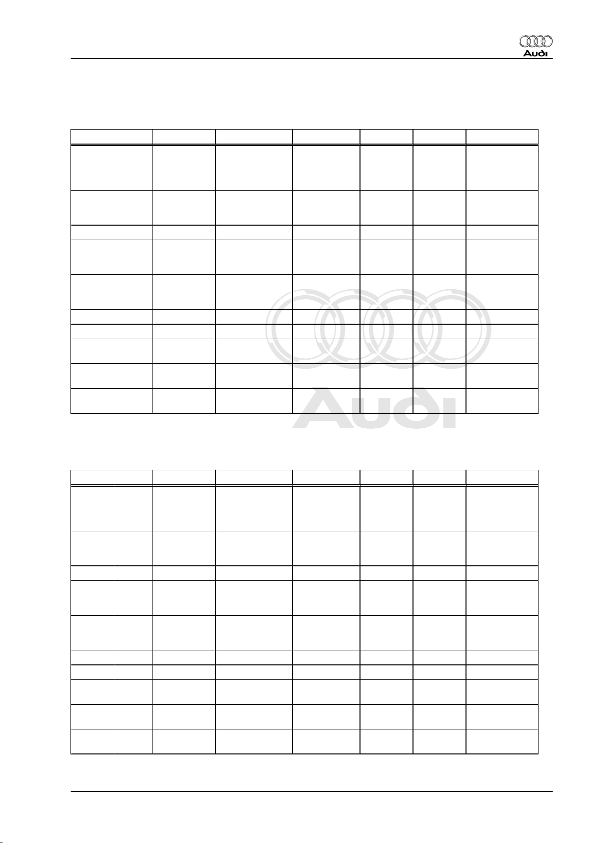
1 Overview of engines
Petrol engines
Engine code AJQ APP AUQ ARY AUM BVP
kW at
rpm
rpm
EU II + D3 EU II + D3 EU IV EU III EU IV EU IV
4 / 5 4 / 5 4 / 5 4 / 5 4 / 5 4 / 5
132/
5500...6000
235/
2000...4600
132/
5500...6000
235/
2000...4600
132/
5500...6000
235/
1950...5000
132/
5500...600
0
235/
1950...500
0
110/
5500...570
0
210/
1750...460
0
1950...4700
9.5 9.5 9.5 9.0 9.5 9.3
Bosch
Motronic
1)
98
Super plus
Bosch
Motronic
1)
98
Super plus
Bosch
Motronic
1)
98
Super plus
Bosch
Motronic
1)
98
Super plus
Bosch
Motronic
2)
95
(unleaded)
Motronic
(unleaded)
120/
5700
225/
Bosch
95
Exhaust
emis‐
sions
standard
No. of cylinders /
valves per cylin‐
der
Capacity ltr. 1.781 1.781 1.781 1.781 1.781 1.781
Power
output
Torque Nm at
Bore ∅ mm 81.0 81.0 81.0 81.0 81.0 81.0
Stroke mm 86.4 86.4 86.4 86.4 86.4 86.4
Compression ra‐
tio
Fuel injection / ig‐
nition
RON min.
2)
1) Unleaded RON 95 can also be used, but will result in a slight loss of power.
2) Unleaded RON 91 can also be used, but will result in a slight loss of power.
Engine code BVR APX AMU BAM BFV BHE
Exhaust
EU IV EU II + D3 EU III EU III EU III EU IV
emis‐
sions
standard
No. of cylinders /
4/5 4 / 5 4 / 5 4/5 4/5 6/4
valves per cylin‐
der
Capacity ltr. 1.781 1.781 1.781 1.781 1.781 3.189
Power
output
kW at
rpm
140/
5700
165/
5500...6000
165/
5500...6000
165/
5500...600
176/
5700
184/
6300
0
Torque Nm at
rpm
240/
1980...5400
280/
2200...5500
280/
2200...5500
280/
2200...550
0
320/
2300...500
0
320/
2800...3200
Bore ∅ mm 81 81.0 81.0 81.0 81 84.0
Stroke mm 86.4 86.4 86.4 86.4 86.4 31.9
Compression ra‐
9.3 9.0 9.0 9.0 8.9 11.3
tio
Fuel injection / ig‐
nition
RON min.
Bosch
Motronic
3)
98
Super plus
Bosch
Motronic
3)
98
Super plus
Bosch
Motronic
3)
98
Super plus
Bosch
Motronic
3)
98
Super plus
Bosch
Motronic
3)
98
Super plus
Bosch
Motronic
98
Super plus
3)
1. Overview of engines 1
Page 6

Protected by copyright. Copying for private or commercial purposes, in part or in whole, is not
permitted unless authorised by AUDI AG. AUDI AG does not guarantee or accept any liability
with respect to the correctness of information in this document. Copyright by AUDI AG.
Audi TT 1999 ➤
Maintenance - Edition 06.2007
3) Unleaded RON 95 can also be used, but will result in a slight loss of power.
2 1. Overview of engines
Page 7
Protected by copyright. Copying for private or commercial purposes, in part or in whole, is not
permitted unless authorised by AUDI AG. AUDI AG does not guarantee or accept any liability
with respect to the correctness of information in this document. Copyright by AUDI AG.
Maintenance - Edition 06.2007
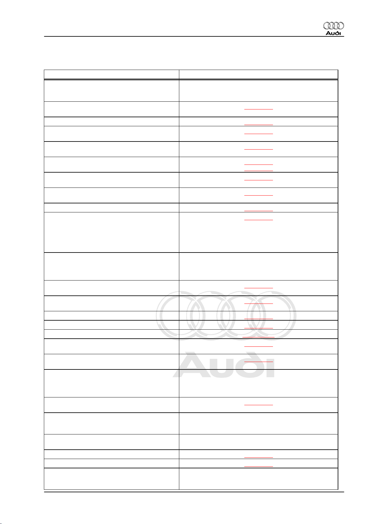
2 Delivery Inspection
Work to be completed Page
In the case of stock vehicles: perform steps
specified in Technical Service Handbook; “In‐
spection and Maintenance”; Chapter 6
Battery: checking that battery cables are secure‐
ly fitted
Battery: performing load test ⇒ page 14
Engine (from above) and engine compartment:
visual check for leaks and damage
Cooling system: coolant must be filled to max.
level
Windscreen and headlight washer system: must
be filled to max. level
Engine: checking oil level and topping up if nec‐
essary
Brake system: brake fluid must be filled to max.
level
Hydraulic system: checking fluid level ⇒ page 34
Transport locks: removing locking elements for
front suspension struts
Please note: If there is a “warning” notice (orange
tag) attached to the interior mirror, the locking el‐
ements for rear suspension struts (on both sides)
must also be removed.
Underside of vehicle, mechanical units, steering,
boots, brake system, hoses, fluid reservoirs: vis‐
ual check for leaks and damage (without disman‐
tling noise insulation)
Underside of vehicle (underbody): visual check
for damage
Tyre pressure on all 4 wheels and spare wheel:
check (note: 3.5 bar when car leaves factory)
Wheel bolts: tightening to specified torque ⇒ page 46
Electric windows: checking positions ⇒ page 30
Clock: setting ⇒ page 100
Air conditioner: checking operation and setting
temperature to 22 °C
Radio or Radio/Navigation System Plus (Chorus,
Concert): Deactivating transport mode
Radio: sticking label with serial number and fixed
code number (see vehicle data sticker) onto radio
card
(included with radio operating instructions)
Radio: activating anti-theft coding by entering
fixed code number
Radio: storing local radio stations on station but‐
tons (on RDS radios, do not store until station
name appears on display)
Telephone: sticking label with serial number in
telephone operating instructions
Instrument cluster: setting the language ⇒ page 35
Service interval display: resetting ⇒ page 64
Passenger's airbag: checking key switch on / off,
must be set to “on”.
(see Owner's Manual)
⇒ page 16
⇒ page 41
⇒ page 37
⇒ page 51
⇒ page 51
⇒ page 45
⇒ page 22
⇒ page 98
⇒ page 98
⇒ page 22
⇒ page 36
⇒ page 46
⇒ page 49
Audi TT 1999 ➤
2. Delivery Inspection 3
Page 8
Protected by copyright. Copying for private or commercial purposes, in part or in whole, is not
permitted unless authorised by AUDI AG. AUDI AG does not guarantee or accept any liability
with respect to the correctness of information in this document. Copyright by AUDI AG.
Audi TT 1999 ➤
Maintenance - Edition 06.2007
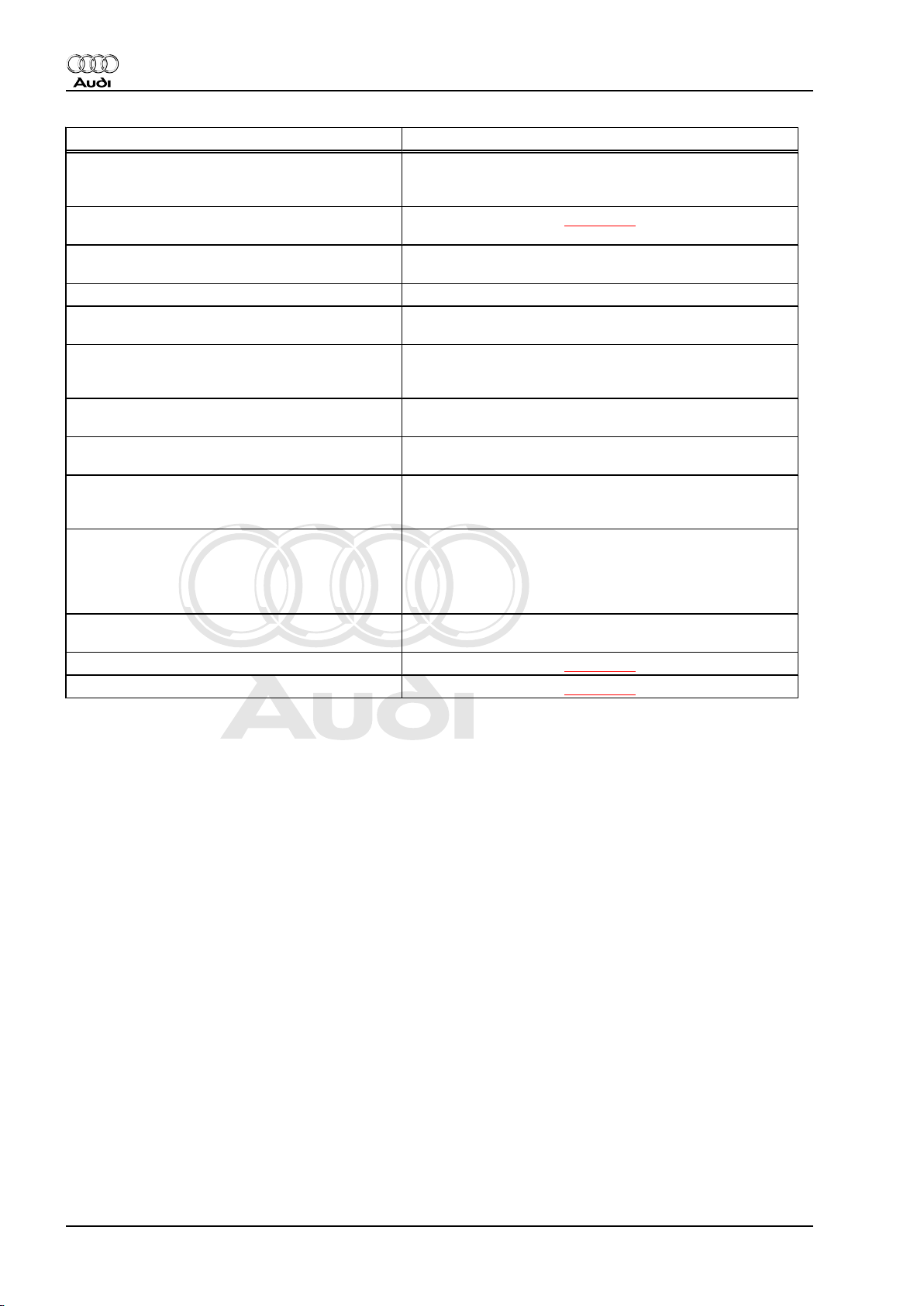
Work to be completed Page
All control units: interrogating fault memory
(Enter “00” for address word “Automatic test se‐
quence”)
Windscreen washer jets: adjusting height of
⇒ page 50
spray area
Protective seat covers and plastic sheeting for
carpet: removing
Floor mats: fitting
Cleanliness of vehicle interior: checking front and
rear seats, interior trim, carpeting/mats, windows
Fitting wheel covers/hub trim caps, roof aerial,
telephone aerial (components stored in luggage
compartment)
Transport protection: removing protective edge
strips on doors
Cleanliness of vehicle exterior: checking paint‐
work, trims, windows, wiper blades
Audi sticker: enter next service (and date for
brake fluid change) and affix sticker on left of
dash panel or on door post (B-pillar)
Service Schedule: removing vehicle data sticker
from spare wheel well or luggage compartment
floor and sticking into Service Schedule under
“Warranty entitlement record”. Entering Delivery
Inspection.
Owner's literature: checking that it is complete
and preparing for handover to customer
Vehicle keys: checking operation ⇒ page 30
Road test ⇒ page 45
4 2. Delivery Inspection
Page 9

Protected by copyright. Copying for private or commercial purposes, in part or in whole, is not
permitted unless authorised by AUDI AG. AUDI AG does not guarantee or accept any liability
with respect to the correctness of information in this document. Copyright by AUDI AG.
3 LongLife Service
Vehicles built model year 2000 > -Y-
Note
♦
Belgium
♦
Denmark
♦
Germany
♦
Finland
♦
France
♦
Gibraltar
♦
Greece
♦
Great Britain
♦
Ireland
♦
Iceland
♦
Italy
♦
Canary Islands
♦
Luxembourg
♦
Malta
♦
Netherlands
♦
Norway
♦
Austria
♦
Portugal
♦
Sweden
♦
Switzerland/Liechtenstein
Audi TT 1999 ➤
Maintenance - Edition 06.2007
♦
Spain/Andorra
♦
Cyprus
♦
Japan (from August 2002)
♦
Czech Republic (from 2003)
Extended servicing intervals
♦ Vehicles with petrol engine/ turbocharged petrol engine: max.
30,000 km (20,000 miles) or max. 2 years, oil grade 2
♦ The oil grade must be entered in the instrument cluster.
LongLife engine oil
New VW standard (specially developed, resistant to ageing) ac‐
cording to specification:
-VW 503 00- or -VW 504 00- for petrol engines / turbocharged
petrol engines (110 / 120 / 132 / 140 / 184 kW)
-VW 503 01- or -VW 504 00- for turbocharged petrol engines
(165 / 176 kW)
3. LongLife Service 5
Page 10
Protected by copyright. Copying for private or commercial purposes, in part or in whole, is not
permitted unless authorised by AUDI AG. AUDI AG does not guarantee or accept any liability
with respect to the correctness of information in this document. Copyright by AUDI AG.
Audi TT 1999 ➤
Maintenance - Edition 06.2007
Work to be completed
The order of the individual servicing operations is optimised
as a result of long-standing experience. It is therefore essen‐
tial to comply with the stated order to avoid unnecessary
delays.
The order in which operations are described here is based on
that specified for the Inspection Service, which is the type of
service performed most frequently.
Please inform the customer if any faults or defects which need
repairing are identified during an Inspection Service.
Interval Work to be completed
according to
All work to be completed except for jobs marked "XX"
service interval
display
every 60,000 km
All work to be completed including jobs marked "XX"
(40,000 miles)
every 30,000 km
(20,000 miles)
In addition to LongLife Service:
♦ Change oil for Haldex coupling
♦ Direct shift gearbox (DSG) tiptronic: changing oil and re‐
newing oil filter (only on vehicles with chassis no.
8N_41000189 to 8N_1009705)
every 60,000 km
(40,000 miles)
In addition to LongLife Service:
♦ Direct shift gearbox (DSG) tiptronic: changing oil and re‐
newing oil filter
♦ Haldex coupling: changing oil and renewing oil filter
every 120,000
km
(80,000 miles)
In addition to LongLife Service:
– Poly V-belt and toothed belt: renewing
♦ 1.8 ltr. 165 kW turbocharged engines from model year 2001
onwards
♦ 1.8 ltr. 176 kW turbocharged engines
every 180,000
km
(115,000 miles)
In addition to LongLife Service:
– Poly V-belt and toothed belt: renewing
♦ 1.8 ltr. 132 kW turbocharged engines from model year 2001
onwards
♦ 1.8 ltr. 110 kW turbocharged engines
♦ 1.8 ltr. 120 kW turbocharged engines
♦ 1.8 ltr. 140 kW turbocharged engines
⇒ page 33
⇒ page 30
⇒ page 30
⇒ page 99
⇒ page 99
every 180,000
km
(115,000 miles)
or every 5 years
In addition to LongLife Service:
– Poly V-belt and toothed belt: renewing
♦ 1.8 ltr. 132 kW turbocharged engines up to model year
2000
♦ 1.8 ltr. 165 kW turbocharged engines up to model year
2000
every 24 months In addition to LongLife Service:
– Brake fluid: changing
Work to be com‐
pleted B
Work to be completed Page
Electrical system
6 3. LongLife Service
⇒ page 99
⇒ page 23
Page 11
Protected by copyright. Copying for private or commercial purposes, in part or in whole, is not
permitted unless authorised by AUDI AG. AUDI AG does not guarantee or accept any liability
with respect to the correctness of information in this document. Copyright by AUDI AG.
Maintenance - Edition 06.2007
Work to be completed Page
Front lighting - checking operation: side lights, dipped
headlights, main beam headlights, fog lights, turn sig‐
nals, hazard warning lights
Rear lighting - checking operation: brake lights (incl.
3rd brake light), rear lights, reversing lights, rear fog
light, number plate lights, turn signals, hazard warn‐
ing lights, luggage compartment light
Interior lights and glove box lights, warning and indi‐
cator lamps, horn: checking operation
Self-diagnosis: interrogating fault memory with fault
⇒ page 31
reader -V.A.G 1551- or -VAS 5051Service interval display: resetting LongLife Service
⇒ page 64
(from chassis No. 8NY1 050 000 onwards)
Vehicle, from outside
Door arresters, lock cylinder and bonnet arrester
⇒ page 97
hook: lubricating
Windscreen wiper/washer system and headlight
⇒ page 50
washer system: checking jet settings and operation
Wiper blades in park position: checking ⇒ page 58
Only in the case of “juddering” wiper blades: checking
⇒ page 58
setting angle
Wiper blades: checking for damage
Tyres
Tyre on spare wheel: checking condition and wear
⇒ page 21
pattern; entering tread depth
Tyre (front left): checking condition and wear pattern;
⇒ page 21
entering tread depth
Tyre (rear left): checking condition and wear pattern;
entering tread depth
Tyre (rear right): checking condition and wear pattern;
entering tread depth
Tyre (front right): checking condition and wear pat‐
⇒ page 21
⇒ page 21
⇒ page 21
tern; entering tread depth
Tyre repair kit: checking expiry date ⇒ page 46
Vehicle, from below:
Engine, gearbox, final drive, steering and boots: vis‐
ual checks for leaks and damage
Engine oil: draining or extracting, changing oil filter ⇒ page 42
Manual gearbox/final drive: checking oil level, topping
⇒ page 50
up with oil if necessary
Haldex coupling: changing oil (four-wheel drive) / ad‐
⇒ page 33
ditional work
Haldex coupling: renewing oil filter (four-wheel drive) /
⇒ page 34
additional work
Brake system: visual check for leaks and damage ⇒ page 22
Brake pads: checking thickness ⇒ page 29
Underseal: visual check for damage ⇒ page 98
Exhaust system: visual check for leaks and damage,
check that parts are properly secured
Track rod ball joints: checking play, security and
⇒ page 97
boots
Swivel joints: checking play, checking boots for leaks
and damage
Engine compartment
Audi TT 1999 ➤
3. LongLife Service 7
Page 12
Protected by copyright. Copying for private or commercial purposes, in part or in whole, is not
permitted unless authorised by AUDI AG. AUDI AG does not guarantee or accept any liability
with respect to the correctness of information in this document. Copyright by AUDI AG.
Audi TT 1999 ➤
Maintenance - Edition 06.2007
Work to be completed Page
Engine (from above) and engine compartment: visual
⇒ page 41
check for leaks and damage
Engine oil: filling up ⇒ page 44
Battery: checking electrolyte level, topping up with
⇒ page 16
distilled water if necessary
Battery with magic eye: checking display, topping up
with distilled water if necessary
Windscreen and headlight washer system: topping up
⇒ page 58
with washer fluid
Cooling system: checking antifreeze and coolant lev‐
⇒ page 37
el / antifreeze specified value -25°C; actual value
(measured value):
XXHydraulic system: checking for leaks, checking hy‐
⇒ page 34
draulic fluid level and topping up if necessary
XXAir cleaner: cleaning housing and renewing filter ele‐
⇒ page 40
ment
XXSpark plugs: renewing ⇒ page 100
Dust and pollen filter: renewing ⇒ page 49
Plenum chamber: checking water drain ⇒ page 99
Poly V-belt: renewing - additional work ⇒ page 39
Toothed belt: renewing - additional work ⇒ page 39
Brake fluid: changing (every two years) - additional
⇒ page 23
work
Note: Never remove strainer from brake fluid reser‐
voir
Final jobs
Tyre pressures on all 4 wheels and spare wheel:
⇒ page 22
checking
Headlights, ellipsoid headlights: checking settings
and adjusting if necessary
Gas discharge headlights: checking settings and ad‐
⇒ page 51
⇒ page 53
justing if necessary
Sticker: enter next service (and date for brake fluid
change) and affix sticker on left side of dash panel or
on door post (B-pillar)
Road test ⇒ page 45
8 3. LongLife Service
Page 13
Protected by copyright. Copying for private or commercial purposes, in part or in whole, is not
permitted unless authorised by AUDI AG. AUDI AG does not guarantee or accept any liability
with respect to the correctness of information in this document. Copyright by AUDI AG.
4 Oil Change Service
Audi TT 1999 ➤
Maintenance - Edition 06.2007
Work required
Page
every 15,000 km
(10,000 miles)
or 12 months
Engine oil: draining or extracting, changing oil filter ⇒ page 42
Brake pads: checking thickness of disc brake pads ⇒ page 29
Engine oil: filling up ⇒ page 44
Service interval display: resetting (on vehicles up to chassis No.
⇒ page 59
8NY1 049 999)
Service interval display: resetting Inspection Service (from
⇒ page 81
chassis No. 8NY1 050 000 onwards)
4. Oil Change Service 9
Page 14
Protected by copyright. Copying for private or commercial purposes, in part or in whole, is not
permitted unless authorised by AUDI AG. AUDI AG does not guarantee or accept any liability
with respect to the correctness of information in this document. Copyright by AUDI AG.
Audi TT 1999 ➤
Maintenance - Edition 06.2007
5 Inspection Service
Fixed service interval
♦ Vehicles with petrol engine/ turbocharged petrol engine: max.
15,000 km (10,000 miles) or max. 1 year; oil grade 1.
♦ The oil grade must be entered in the instrument cluster.
Inspection Service
In the case of fixed service intervals the following engine oils ac‐
cording to VW standards must be used:
-VW 501 01- , -VW 502 00- or -VW 504 00- for petrol engines /
turbocharged petrol engines
Work to be completed
The order of the individual servicing operations is optimised
as a result of long-standing experience. It is therefore essen‐
tial to comply with the stated order to avoid unnecessary
delays.
The order in which operations are described here is based on
that specified for the Inspection Service, which is the type of
service performed most frequently.
Please inform the customer if any faults or defects which need
repairing are identified during an Inspection Service.
Interval Work to be completed
according to
All work to be completed except for jobs marked "XX"
service interval
display
every 60,000 km
All work to be completed including jobs marked "XX"
(40,000 miles)
every 30,000 km
(20,000 miles)
In addition to Inspection Service:
♦ Change oil for Haldex coupling
♦ Direct shift gearbox (DSG) tiptronic: changing oil and re‐
newing oil filter (only on vehicles with chassis no.
8N_41000189 to 8N_1009705)
every 60,000 km
(40,000 miles)
In addition to Inspection Service:
♦ Direct shift gearbox (DSG) tiptronic: changing oil and re‐
newing oil filter
♦ Haldex coupling: changing oil and renewing oil filter
every 120,000
km
(80,000 miles)
In addition to LongLife Service:
– Poly V-belt and toothed belt: renewing
♦ 1.8 ltr. 165 kW turbocharged engines from model year 2001
onwards
♦ 1.8 ltr. 176 kW turbocharged engines
every 180,000
km (115,000
miles)
In addition to LongLife Service:
– Poly V-belt and toothed belt: renewing
♦ 1.8 ltr. 132 kW turbocharged engines from model year 2001
onwards
♦ 1.8 ltr. 110 kW turbocharged engines
♦ 1.8 ltr. 120 kW turbocharged engines
♦ 1.8 ltr. 140 kW turbocharged engines
⇒ page 33
⇒ page 30
⇒ page 30
⇒ page 99
⇒ page 99
10 5. Inspection Service
Page 15
Protected by copyright. Copying for private or commercial purposes, in part or in whole, is not
permitted unless authorised by AUDI AG. AUDI AG does not guarantee or accept any liability
with respect to the correctness of information in this document. Copyright by AUDI AG.
Audi TT 1999 ➤
Maintenance - Edition 06.2007
Interval Work to be completed
every
180,000 km
(115,000 miles)
/ every 5 years
In addition to LongLife Service:
– Poly V-belt and toothed belt: renewing
♦ 1.8 ltr. 132 kW turbocharged engines up to model year
2000
♦ 1.8 ltr. 165 kW turbocharged engines up to model year
2000
every 24 months In addition to Inspection Service:
– Brake fluid: changing
Work to be com‐
pleted B
Work to be completed Page
Electrical system
Front lighting - checking operation: side lights,
dipped headlights, main beam headlights, fog
lights, turn signals, hazard warning lights
Rear lighting - checking operation: brake lights
(incl. 3rd brake light), rear lights, reversing lights,
rear fog light, number plate lights, turn signals,
hazard warning lights, luggage compartment
light
Interior lights and glove box lights, warning and
indicator lamps, horn: checking operation
Self-diagnosis: interrogating fault memory with
fault reader -V.A.G 1551- or -VAS 5051-
Service interval display: resetting LongLife Serv‐
⇒ page 31
⇒ page 64
ice (from chassis No. 8NY1 050 000 onwards)
Vehicle, from outside
Door arresters, lock cylinder and bonnet arrester
⇒ page 97
hook: lubricating
Windscreen wiper/washer system and headlight
⇒ page 50
washer system: checking jet settings and opera‐
tion
Wiper blades in park position: checking ⇒ page 58
Only in the case of “juddering” wiper blades:
⇒ page 58
checking setting angle
Wiper blades: checking for damage
Tyres
Tyre on spare wheel: checking condition and
⇒ page 21
wear pattern; entering tread depth
Tyre (front left): checking condition and wear pat‐
⇒ page 21
tern; entering tread depth
Tyre (rear left): checking condition and wear pat‐
⇒ page 21
tern; entering tread depth
Tyre (rear right): checking condition and wear
⇒ page 21
pattern; entering tread depth
Tyre (front right): checking condition and wear
⇒ page 21
pattern; entering tread depth
Tyre repair kit: checking expiry date ⇒ page 46
Vehicle, from below:
Engine, gearbox, final drive, steering and boots:
visual checks for leaks and damage
⇒ page 99
⇒ page 23
5. Inspection Service 11
Page 16
Protected by copyright. Copying for private or commercial purposes, in part or in whole, is not
permitted unless authorised by AUDI AG. AUDI AG does not guarantee or accept any liability
with respect to the correctness of information in this document. Copyright by AUDI AG.
Audi TT 1999 ➤
Maintenance - Edition 06.2007
Work to be completed Page
Engine oil: draining or extracting, changing oil fil‐
⇒ page 42
ter
Manual gearbox/final drive: checking oil level,
⇒ page 50
topping up with oil if necessary
Haldex coupling: changing oil (four-wheel drive) /
⇒ page 33
additional work
Haldex coupling: renewing oil filter (four-wheel
⇒ page 34
drive) / additional work
Brake system: visual check for leaks and dam‐
⇒ page 22
age
Brake pads: checking thickness ⇒ page 29
Underseal: visual check for damage ⇒ page 98
Exhaust system: visual check for leaks and dam‐
age, check that parts are properly secured
Track rod ball joints: checking play, security and
⇒ page 97
boots
Swivel joints: checking play, checking boots for
leaks and damage
Engine compartment
Engine (from above) and engine compartment:
⇒ page 41
visual check for leaks and damage
Engine oil: filling up ⇒ page 44
Battery: checking electrolyte level, topping up
⇒ page 16
with distilled water if necessary
Battery with magic eye: checking display, topping
up with distilled water if necessary
Windscreen and headlight washer system: top‐
⇒ page 58
ping up with washer fluid
Cooling system: checking antifreeze and coolant
⇒ page 37
level / antifreeze specified value -25°C; actual
value (measured value):
XXHydraulic system: checking for leaks, checking
⇒ page 34
hydraulic fluid level and topping up if necessary
XXAir cleaner: cleaning housing and renewing filter
⇒ page 40
element
XXSpark plugs: renewing ⇒ page 100
Dust and pollen filter: renewing ⇒ page 49
Plenum chamber: checking water drain ⇒ page 99
Poly V-belt: renewing - additional work ⇒ page 39
Toothed belt: renewing - additional work ⇒ page 39
Brake fluid: changing (every two years) - addi‐
⇒ page 23
tional work
Note: Never remove strainer from brake fluid res‐
ervoir
Final jobs
Tyre pressures on all 4 wheels and spare wheel:
checking
Headlights, ellipsoid headlights: checking set‐
⇒ page 22
⇒ page 51
tings and adjusting if necessary
Gas discharge headlights: checking settings and
⇒ page 53
adjusting if necessary
Sticker: enter next service (and date for brake
fluid change) and affix sticker on left side of dash
panel or on door post (B-pillar)
12 5. Inspection Service
Page 17

Protected by copyright. Copying for private or commercial purposes, in part or in whole, is not
permitted unless authorised by AUDI AG. AUDI AG does not guarantee or accept any liability
with respect to the correctness of information in this document. Copyright by AUDI AG.
Maintenance - Edition 06.2007
Work to be completed Page
Road test ⇒ page 45
Audi TT 1999 ➤
5. Inspection Service 13
Page 18
Protected by copyright. Copying for private or commercial purposes, in part or in whole, is not
permitted unless authorised by AUDI AG. AUDI AG does not guarantee or accept any liability
with respect to the correctness of information in this document. Copyright by AUDI AG.
Audi TT 1999 ➤
Maintenance - Edition 06.2007
6 Description of work
6.1 Battery: performing load test
The battery load test provides information on the condition of the
battery.
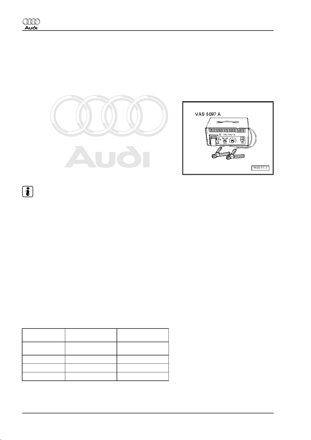
Special tools and workshop equipment required
♦ Battery tester -VAS 5097 A-
Note
It is not necessary to remove the battery when using battery tester
-VAS 5097 A- . The battery does not have to be disconnected.
Carrying out load test
– Switch off ignition.
– Read operating instructions for battery tester.
– Connect the clamps of the test leads to battery terminals as
described in operating instructions for the tester.
The clamps must make good contact with the battery terminals.
– As the load current differs depending on the battery, the cur‐
rent must be set on the tester according to battery capacity ⇒
Operating instructions for battery test equipment.
– Perform a battery load test as described in the operating in‐
structions.
Test equipment display during load test
Please note the test results shown on the display of the tester.
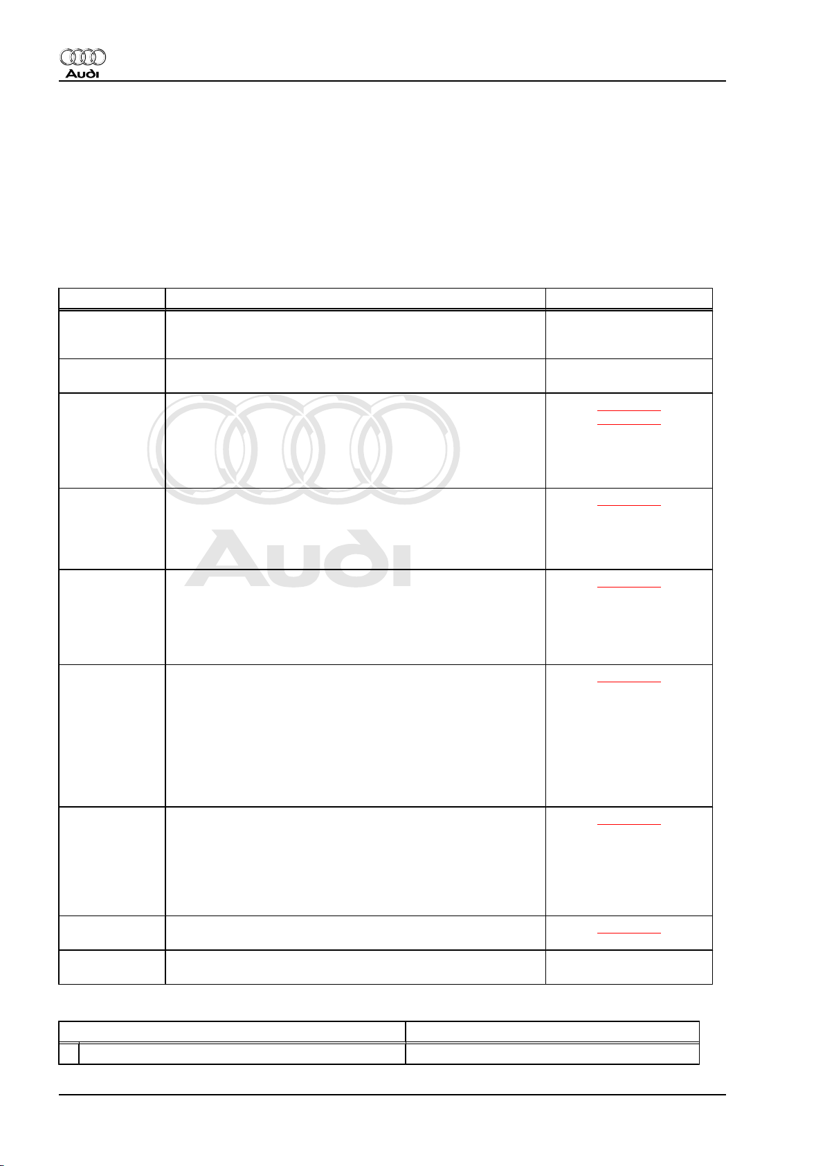
Table:
Display on bat‐
tery tester
Battery Very
Delivery Inspection Inspection Service
LongLife Service
Battery OK Battery OK
Good
Battery Good
Battery Not Good
Charge battery
Charge battery
Battery Faulty Renew battery
1)
1)
Battery OK
Charge battery
Renew battery
1)
2)
1) - Perform battery load test again after recharging the battery.
If tester shows “Battery Good” after charging battery, battery is
OK. However, if tester still shows “Battery Not Good”, battery must
be renewed.
14 6. Description of work
Page 19
Protected by copyright. Copying for private or commercial purposes, in part or in whole, is not
permitted unless authorised by AUDI AG. AUDI AG does not guarantee or accept any liability
with respect to the correctness of information in this document. Copyright by AUDI AG.
2) - Agree battery replacement with customer.
– Renewing the battery ⇒ Electrical system; Repair group 27;
Removing and installing battery .
Notes on battery load test:
The battery voltage will decrease during the test due to the high
load (high current flow).
If a battery is in working order battery voltage will only drop to
minimum voltage.
If the battery is defective or only insufficiently charged, battery
voltage will very quickly drop below minimum voltage.
After carrying out the load test the voltage will remain at this low
level for quite a while; voltage will only rise again slowly.
6.2 Battery: checking "no load" voltage be‐
fore starting the engine for the first time
(only applies to stock vehicles)
Special tools and workshop equipment required
♦ Digital multimeter -V.A.G 1715-
♦ or
♦ Hand-held multimeter -V.A.G 1526 B-
Audi TT 1999 ➤
Maintenance - Edition 06.2007
Note
♦
The vehicle must not be driven or started with the battery that
is to be tested for at least 2 hours before performing test.
♦
The battery must not be placed under load from connected
electrical equipment for at least 2 hours before the test.
♦
The battery must not be charged for at least 2 hours before
the test.
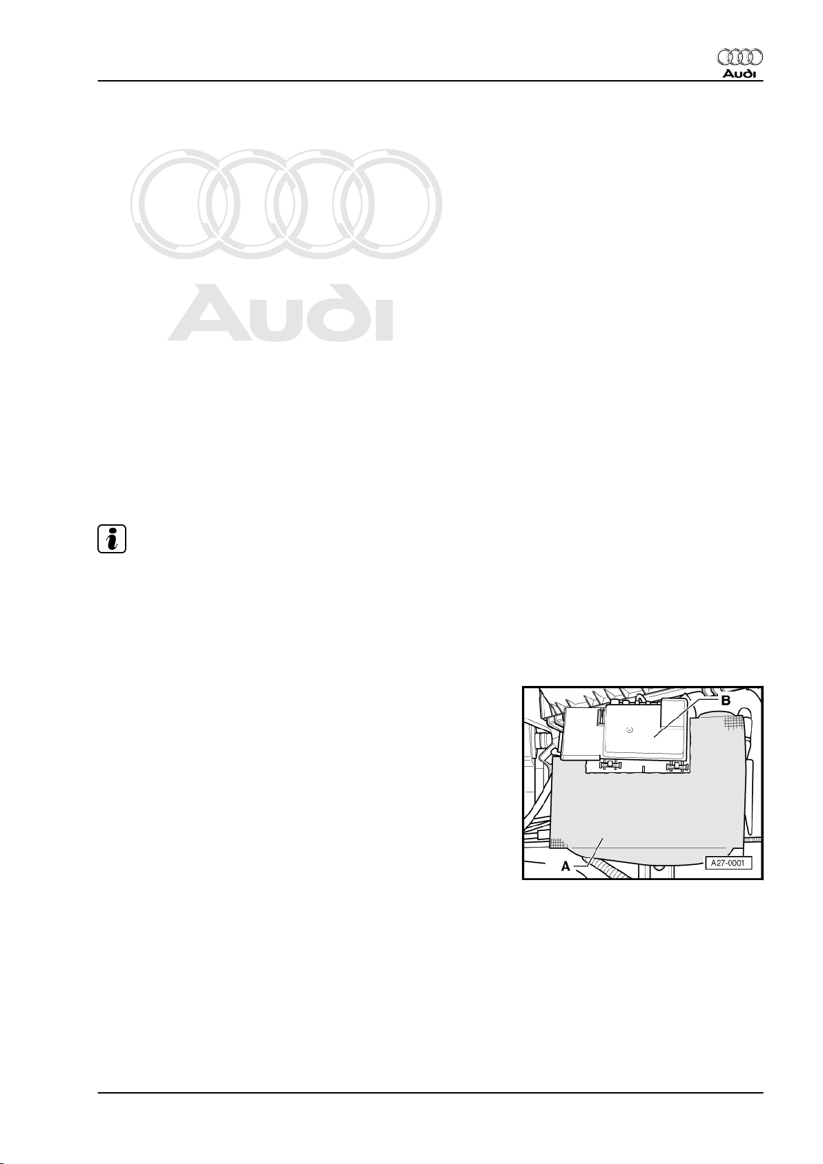
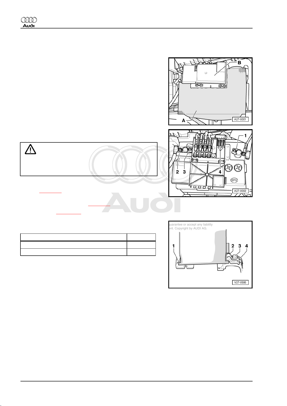
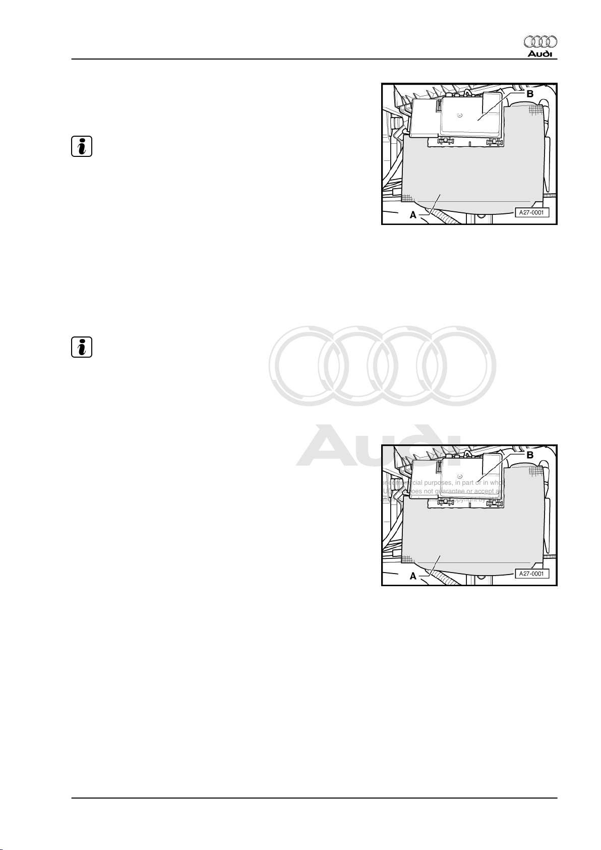
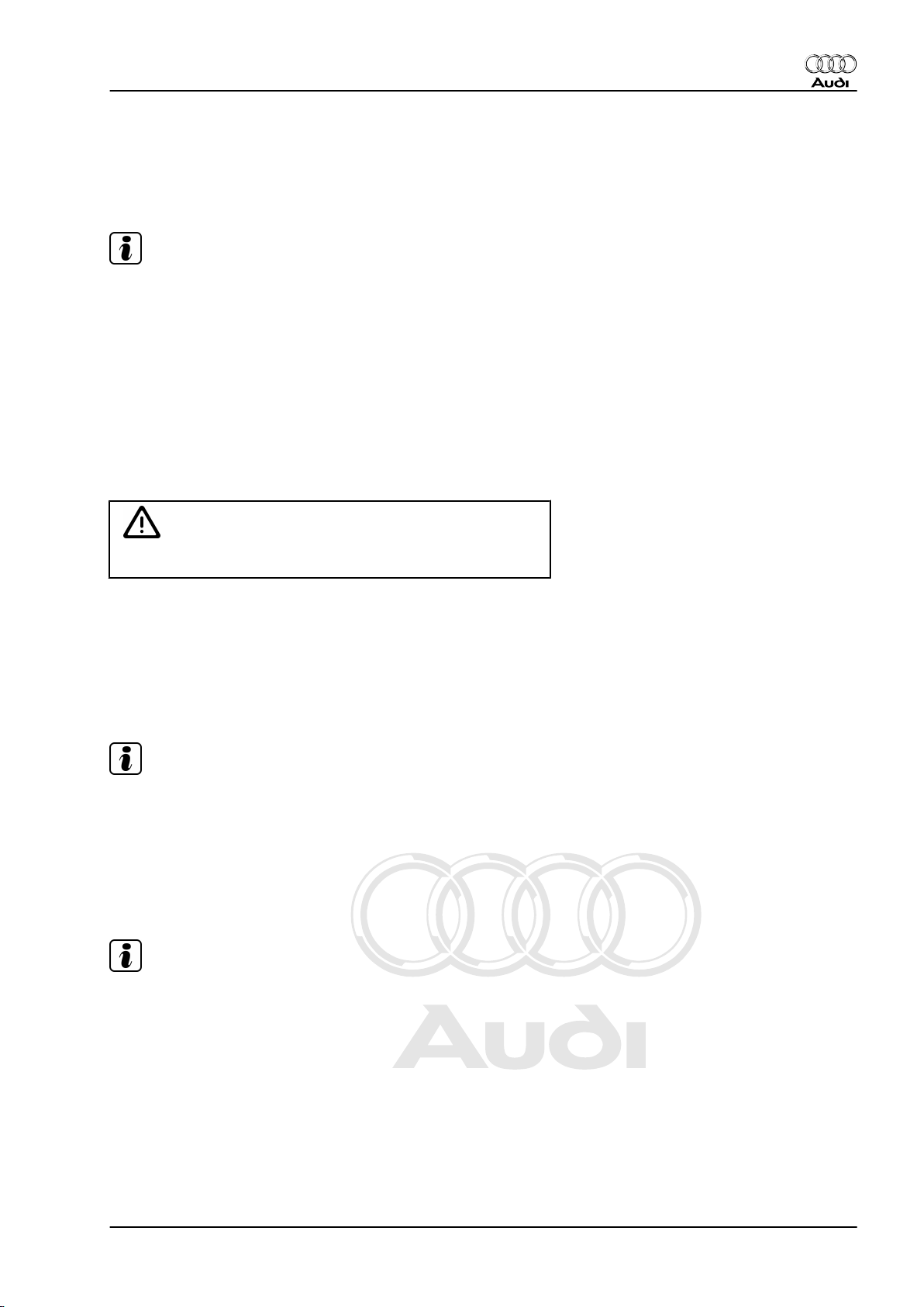
– Open the protective cover on the battery -A- (velcro fastener).
– Open lid -B- of main fuse box towards front of vehicle.
– Check voltage between battery terminals with the ignition
switched off.
♦ If the tester indicates 12.5 V or more, then the battery is OK.
♦ If the voltage is less than 12.5 V, locate the source of the
problem (repair measure).
6. Description of work 15
Page 20
Protected by copyright. Copying for private or commercial purposes, in part or in whole, is not
permitted unless authorised by AUDI AG. AUDI AG does not guarantee or accept any liability
with respect to the correctness of information in this document. Copyright by AUDI AG.
Audi TT 1999 ➤
Maintenance - Edition 06.2007
6.3 Battery: checking that battery cables are securely fitted
– Open the protective cover on the battery -A- (velcro fastener).
– Open lid -B- of main fuse box towards front of vehicle.
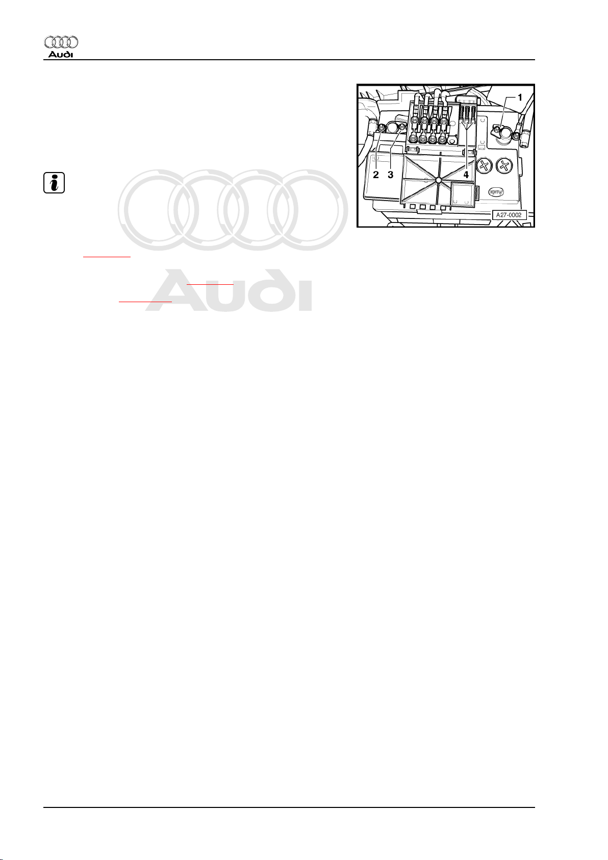
– Check that the battery terminal clamps are securely fitted. If
necessary, tighten nuts -1- and -3-.
WARNING
If the battery terminal clamp on the positive terminal is not fitted
securely, disconnect the battery earth strap from the battery
negative terminal first to avoid possible accidents.
– After connecting battery earth strap, enter anti-theft code for
radio ⇒ page 49 .
– Activate the automatic one-touch function for opening and
closing the electric windows ⇒ page 30 .
– Set the clock ⇒ page 100 .
– Check that battery is securely installed. If necessary tighten
securing bolt -3- on retainer plate -2-.
Tightening torque Nm
Battery terminal clamp to battery terminal 5
Bolt on retainer plate 22
6.4 Battery: checking electrolyte level, top‐
ping up with distilled water if necessary
The battery is located in the engine compartment (front left).
16 6. Description of work
Page 21
Protected by copyright. Copying for private or commercial purposes, in part or in whole, is not
permitted unless authorised by AUDI AG. AUDI AG does not guarantee or accept any liability
with respect to the correctness of information in this document. Copyright by AUDI AG.
– Open the protective cover on the battery -A- (velcro fastener)
and push slightly downwards.
♦ The electrolyte level must be between min. and max. marks
Note
♦
For batteries with clearly visible min. and max. mark, a visual
check of the battery is sufficient.
♦
If the external min. and max. marks on the battery are not
clearly visible or if the electrolyte level cannot be checked
properly due to an opaque battery housing, the sealing plugs
must be unscrewed ⇒ Topping up with distilled water.
♦
The electrolyte level must align with the marking inside the
battery (plastic moulding). This corresponds to the max mark‐
ing on the outside.
– If necessary, top up battery cells to max. mark with distilled
water.
Topping up with distilled water
Audi TT 1999 ➤
Maintenance - Edition 06.2007
Note
The centre sealing plugs on the battery are concealed by the
bracket for the main fuse box. To unscrew these sealing plugs
you must first remove the main fuse box.
– In the case of vehicles with anti-theft code you will require the
correct code; if necessary obtain the code beforehand.
– Open lid -B- of main fuse box towards front of vehicle.
6. Description of work 17
Page 22
Protected by copyright. Copying for private or commercial purposes, in part or in whole, is not
permitted unless authorised by AUDI AG. AUDI AG does not guarantee or accept any liability
with respect to the correctness of information in this document. Copyright by AUDI AG.
Audi TT 1999 ➤
Maintenance - Edition 06.2007
– Slacken hexagon nut -1- and disconnect battery earth strap.
– Remove the hexagon nut -2- and detach retaining brackets for
main fuse box from battery housing.
– Remove the sealing plugs.
– Only top up the electrolyte level with distilled water.
Note
The use of distilled water prevents contamination of the electro‐
lyte and any associated increase in self discharge.
– After connecting battery earth strap, enter anti-theft code for
radio ⇒ page 49 .
– Activate the automatic one-touch function for opening and
closing the electric windows ⇒ page 30 .
– Set the clock ⇒ page 100 .
Batteries with magic eye
18 6. Description of work
Page 23
Protected by copyright. Copying for private or commercial purposes, in part or in whole, is not
permitted unless authorised by AUDI AG. AUDI AG does not guarantee or accept any liability
with respect to the correctness of information in this document. Copyright by AUDI AG.
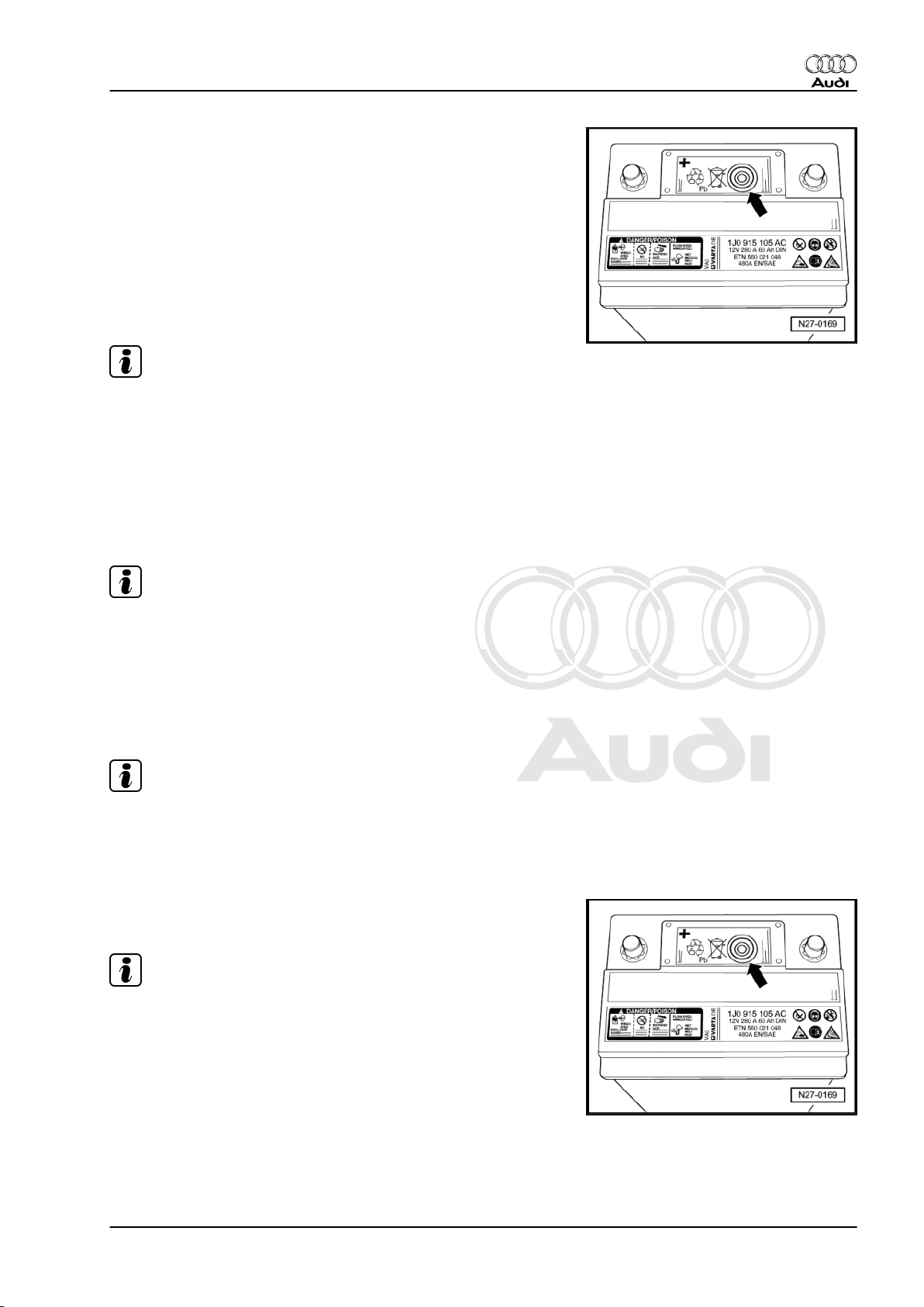
– In the case of batteries (lead-calcium batteries) with magic eye
-arrow- please carry out check as follows:
The magic eye indicates the electrolyte level and the charge level
of the battery. Three different colours are used as indicators:
Green → the battery is sufficiently charged.
Black → no charge or charge too low (repair measure).
Colourless or yellow → critical electrolyte level has been reached.
It is essential to top up with distilled water:
– Remove the foil covering the sealing plug.
Note
♦
Sealed starter batteries have been fitted from week 01, model
year 2001.
♦
On these batteries it is not possible to measure relative density
or top up with distilled water.
– Unscrew sealing plug from battery.
– Use battery filler bottle -VAS 5045- to top up with distilled water
to max. mark.
Audi TT 1999 ➤
Maintenance - Edition 06.2007
Note
The neck of filler bottle -VAS 5045- is designed to prevent over‐
filling of the battery cells and spillage of battery acid. When the
"max." level is reached, the flow of distilled water into the cells is
cut off.
– Screw the sealing plug back onto battery.
Electrolyte level too high
Note
If the electrolyte level is too high (above the max. marking) the
leaking electrolyte (sulphuric acid/water mixture) will cause dam‐
age outside the battery, e. g. to components in engine compart‐
ment.
– The foil covering the sealing plug must be pulled off on bat‐
teries with magic eye -arrow-.
Note
♦
Sealed starter batteries have been fitted from week 01, model
year 2001.
♦
On these batteries it is not possible to measure relative density
or top up with distilled water.
– Unscrew sealing plug from battery.
If the electrolyte level is too high (over-filled), e.g. is above inner
mark for electrolyte level (plastic moulding) or above the exterior
max. marking:
6. Description of work 19
Page 24
Protected by copyright. Copying for private or commercial purposes, in part or in whole, is not
permitted unless authorised by AUDI AG. AUDI AG does not guarantee or accept any liability
with respect to the correctness of information in this document. Copyright by AUDI AG.
Audi TT 1999 ➤
Maintenance - Edition 06.2007
– Draw off electrolyte with a hydrometer (⇒ illustration) until the
electrolyte level reaches the plastic moulding or the max.
marking.
Note
Observe disposal regulations.
– Screw the sealing plug back onto battery.
6.5 Lights, electrical equipment, switches,
displays and other driver-operated con‐
trols: checking operation
– The following components must be checked:
♦ Lighting, headlights, fog lights, turn signals, hazard warning
lights, rear lights, rear fog light, reversing lights, brake lights,
parking light function
♦ Interior lights and reading lights (automatic switch-off function
for front interior light), glove box lighting, ashtray light, luggage
compartment lighting, ignition key light
♦ Warning buzzer indicating that lights and/or radio have been
left on
♦ All switches on console
♦ Driver Information System (DIS)
♦ Instrument cluster including all displays, counters, lights and
illumination
♦ Dual-tone horn
♦ Windscreen wiper/washer system, headlight washer system
♦ Cigarette lighter
♦ Electric exterior mirrors (heated, adjustable)
♦ Electric window lifters
♦ Central locking, remote control (radio-operated), convenience
close function
♦ Seat heating
♦ Radio
20 6. Description of work
Page 25
Protected by copyright. Copying for private or commercial purposes, in part or in whole, is not
permitted unless authorised by AUDI AG. AUDI AG does not guarantee or accept any liability
with respect to the correctness of information in this document. Copyright by AUDI AG.
6.6 Tyres: checking condition, wear pattern, tread depth and correcting inflation pressures.
Note
In the interest of driving safety, only tyres of the same type and
tread pattern should be fitted on a vehicle.
6.6.1 Checking tyres
Delivery Inspection
– Check tyre tread surfaces and sidewalls for damage and re‐
move any foreign bodies.
Inspection Service
– Check tyres for scuffing, one-sided wear, porous sidewalls,
cuts and fractures.
Audi TT 1999 ➤
Maintenance - Edition 06.2007
WARNING
Any defects must be reported to the customer.
6.6.2 Checking tyre wear pattern
– The wear pattern of the front tyres indicates, for example,
whether the toe and camber have to be checked.
♦ Feathering on tread indicates incorrect toe setting.
♦ One-sided tread wear is usually due to incorrect camber.
Note
If the above types of wear are found, check wheel alignment to
determine the cause (repair measure).
6.6.3 Checking tyre tread depth
– Checking tyre tread depth
♦ Minimum depth: 1.6 mm
Note
♦
This figure may vary for individual countries due to different
legislation.
♦
The minimum tread depth is reached when the tyres have
worn down level with the 1.6 mm high tread wear indicators
positioned at intervals around the tyre.
♦
If the tread depth is approaching the minimum permissible
tread depth, the customer must be informed.
6. Description of work 21
Page 26
Protected by copyright. Copying for private or commercial purposes, in part or in whole, is not
permitted unless authorised by AUDI AG. AUDI AG does not guarantee or accept any liability
with respect to the correctness of information in this document. Copyright by AUDI AG.
Audi TT 1999 ➤
Maintenance - Edition 06.2007
6.6.4 Inflating to correct pressures
The correct inflation pressures for summer tyres are listed on the
sticker on the inside of the tank flap.
Note
♦
Please note that the inflation pressures listed on the sticker
apply to cold tyres. When the tyres are warm, the actual pres‐
sures will be higher, but must not be reduced.
♦
When using winter tyres, pressures should be increased by
0.2 bar.
6.6.5 Spare wheel
• Temporary (compact) spare wheel
The correct inflation pressure is indicated on the sidewall.
Note
Check the valve extensions for damage and dirt which could
cause leaks. Renew if necessary.
6.7 Brake system: visual check for leaks and damage
– Check following components for leaks and damage:
♦ Brake master cylinder
♦ Brake servo
♦ ABS hydraulic unit
♦ Brake calipers
– Ensure that brake hoses are not twisted.
– Make sure that brake hoses do not touch any components
when steering is on full lock.
– Check brake hoses for porosity, blistering and brittleness.
– Check brake hoses and pipes for chafing.
– Check brake pipe connections and mountings for correct seat‐
ing, leaks and corrosion.
WARNING
Any faults found must be rectified (repair measure).
6.8 Brake fluid level (depends on brake pad wear): checking
Only use new genuine VW/Audi brake fluid in accordance with
US standard FMVSS 116 DOT 4.
22 6. Description of work
Page 27
Protected by copyright. Copying for private or commercial purposes, in part or in whole, is not
permitted unless authorised by AUDI AG. AUDI AG does not guarantee or accept any liability
with respect to the correctness of information in this document. Copyright by AUDI AG.
WARNING
♦ Brake fluid is poisonous. It also has caustic properties and
must therefore not be allowed to come into contact with
paintwork.
♦ Brake fluid is hygroscopic, i.e. it absorbs moisture from the
surrounding air. It must therefore always be stored in airtight containers.
– Note the following:
Delivery Inspection
♦ The fluid level must be at the MAX mark.
Note
The fluid level must not exceed the MAX marking, otherwise the
fluid will overflow.
Audi TT 1999 ➤
Maintenance - Edition 06.2007
Inspection Service
When the vehicle is driven, the brake fluid level will drop slightly
with use and as a result of the automatic adjustment of the brake
pads.
– When checking the brake fluid level, always take into account
the amount of wear on the brake pads:
♦ If the brake pads are new or a long way from reaching the wear
limit, the fluid level should be between the MIN and MAX
marks.
♦ If the brake fluid level is at or slightly above the MIN marking
and the brake pads have almost reached the wear limit, top‐
ping up is not required.
WARNING
If the fluid level has fallen below the MIN mark, check the brake
system (repair measure) before adding brake fluid.
6.9 Brake fluid: changing
Note
Only use new genuine VW/Audi brake fluid, refer to ⇒ ETKA .
6. Description of work 23
Page 28
Protected by copyright. Copying for private or commercial purposes, in part or in whole, is not
permitted unless authorised by AUDI AG. AUDI AG does not guarantee or accept any liability
with respect to the correctness of information in this document. Copyright by AUDI AG.
Audi TT 1999 ➤
Maintenance - Edition 06.2007
Changing the brake fluid with brake filling and bleeding equipment
-VAS 5234- ⇒ page 26
Changing the brake fluid with brake filling and bleeding equipment
-V.A.G 1869- ⇒ page 24
WARNING
♦ Brake fluid must on no account come into contact with liq‐
uids containing mineral oils (oil, petrol, cleaning agents).
Mineral oils damage the plugs and sleeves in the brake
system.
♦ Brake fluid is poisonous and must under no circumstances
be sucked through a tube using the mouth. Because of its
caustic properties it must also not come into contact with
paintwork.
♦ Brake fluid is hygroscopic, i.e. it absorbs moisture from the
surrounding air. It must therefore always be stored in airtight containers.
♦ Always observe the relevant environmental regulations for
disposal.
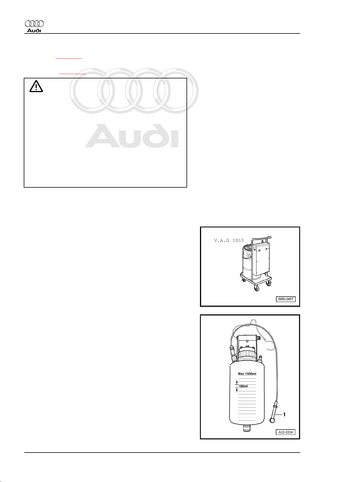
6.9.1 Changing brake fluid with brake filling and bleeding equipment -V.A.G 1869-
Special tools and workshop equipment required
♦ Brake filling and bleeding equipment -V.A.G 1869-
♦ Container for collecting used fluid
24 6. Description of work
Page 29
Protected by copyright. Copying for private or commercial purposes, in part or in whole, is not
permitted unless authorised by AUDI AG. AUDI AG does not guarantee or accept any liability
with respect to the correctness of information in this document. Copyright by AUDI AG.
Note
♦
The brake fluid reservoir must always be adequately filled to
ensure that no air can enter the brake system from the reser‐
voir.
♦
The strainer in the brake fluid reservoir must not be removed.
♦
Observe the instructions given in the operating manual for the
brake filling and bleeding equipment -V.A.G. 1869- .
WARNING
Do not reuse the old brake fluid that has been extracted.
– Open brake fluid reservoir.
– Open the bleeder screw on brake caliper (rear right).
– Get a suitable container ready to catch the used brake fluid.
Audi TT 1999 ➤
Maintenance - Edition 06.2007
6. Description of work 25
Page 30
Protected by copyright. Copying for private or commercial purposes, in part or in whole, is not
permitted unless authorised by AUDI AG. AUDI AG does not guarantee or accept any liability
with respect to the correctness of information in this document. Copyright by AUDI AG.
Audi TT 1999 ➤
Maintenance - Edition 06.2007
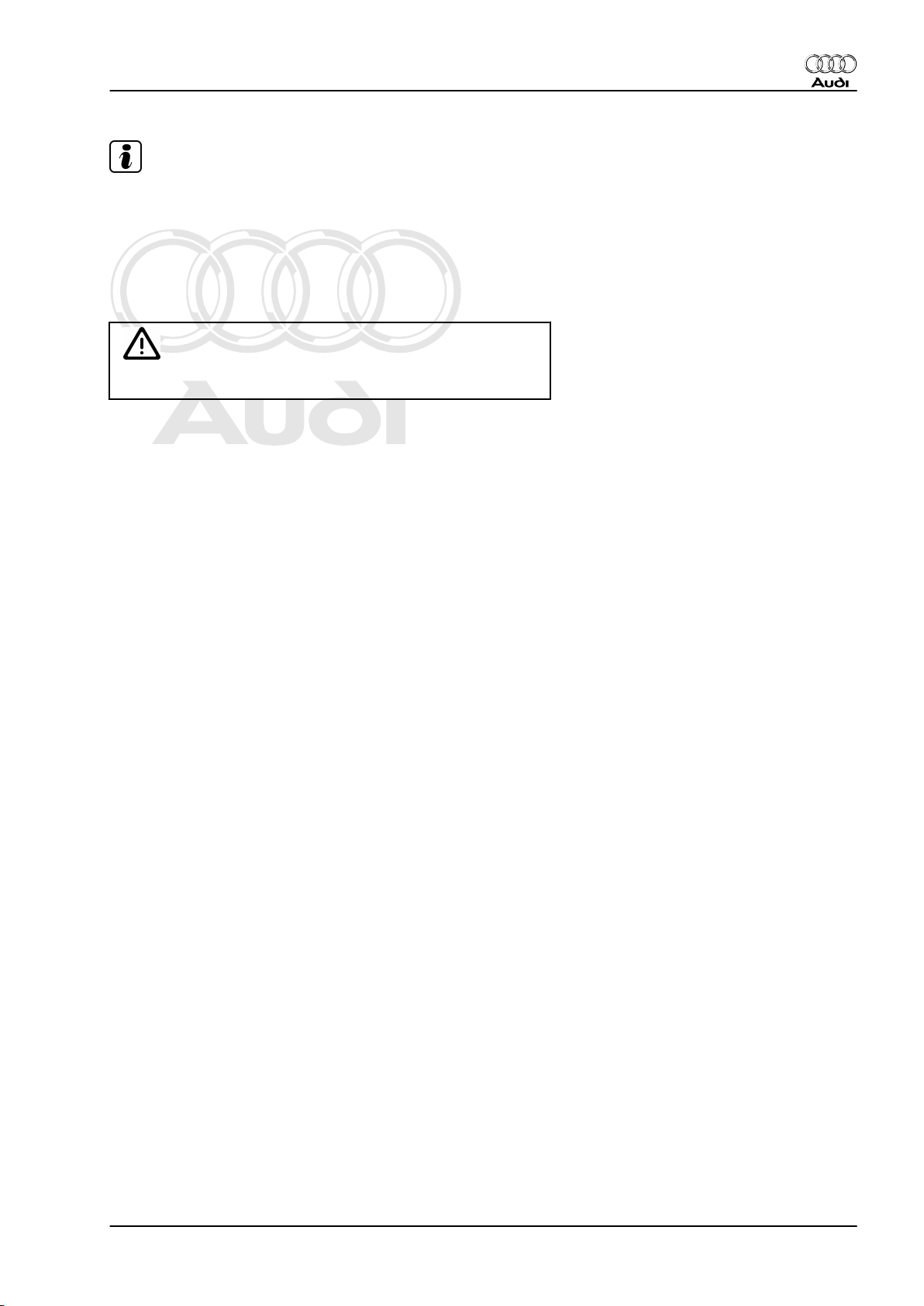
– With engine running, use brake pedal to pump out brake fluid
until fluid level goes down as far as the connection -arrow- on
the reservoir.
– Close bleeder screw.
On vehicles with manual gearbox the clutch slave cylinder must
also be “flushed out” with new brake fluid. When doing so, note
the following:
– Connect brake filling and bleeding equipment -V.A.G 1869- ,
but do not switch on yet.
– Open bleeder screw on clutch slave cylinder.
– Fit bleeder hose leading to brake fluid collector onto bleeder
screw on clutch slave cylinder.
–
Then switch on bleeder appliance and allow about 100 cm3 of
brake fluid to drain out.
– Close bleeder screw.
Sequence for changing brake fluid in brake calipers:
1 - Front left-hand brake caliper
2 - Front right-hand brake caliper
3 - Rear left-hand brake caliper
4 - Rear right-hand brake caliper
– Fit bleeder hose leading to brake fluid collector onto bleeder
screw for relevant brake caliper.
–
Open bleeder screw and allow about 200 cm3 of brake fluid to
drain out.
Used brake fluid is pushed out of the system when new fluid is
pumped in.
– Close bleeder screw.
– Disconnect hose from brake fluid reservoir.
– Check pedal pressure and free play of brake pedal.
♦
Free play: no more than 1/3 of pedal travel
– During the final test drive, make sure that at least one ABS-
controlled brake application is carried out (with noticeable
pulsing of brake pedal).
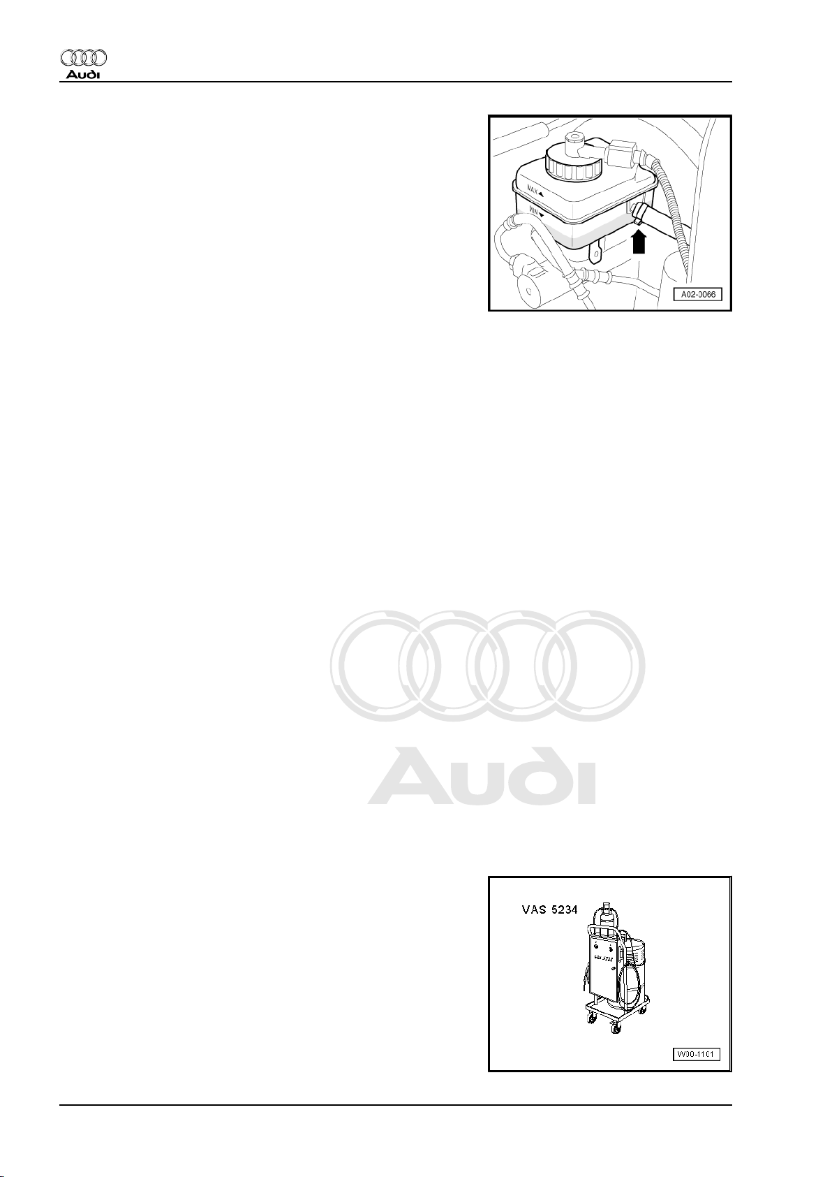
6.9.2 Changing brake fluid with brake filling and bleeding equipment -VAS 5234-
Special tools and workshop equipment required
♦ Brake filling and bleeding equipment -VAS 5234-
26 6. Description of work
Page 31

Protected by copyright. Copying for private or commercial purposes, in part or in whole, is not
permitted unless authorised by AUDI AG. AUDI AG does not guarantee or accept any liability
with respect to the correctness of information in this document. Copyright by AUDI AG.
♦ Container for collecting used fluid
Audi TT 1999 ➤
Maintenance - Edition 06.2007
Note
♦
The brake fluid reservoir must always be adequately filled to
ensure that no air can enter the brake system from the reser‐
voir.
♦
The strainer in the brake fluid reservoir must not be removed.
♦
Observe the instructions given in the operating manual for the
brake filling and bleeding equipment -VAS 5234- .
– Unscrew cap -1- from brake fluid reservoir.
6. Description of work 27
Page 32

Protected by copyright. Copying for private or commercial purposes, in part or in whole, is not
permitted unless authorised by AUDI AG. AUDI AG does not guarantee or accept any liability
with respect to the correctness of information in this document. Copyright by AUDI AG.
Audi TT 1999 ➤
Maintenance - Edition 06.2007
– Use extraction hose included in brake filling and bleeding
equipment -VAS 5234- to extract as much brake fluid as pos‐
sible.
WARNING
Do not reuse the old brake fluid that has been extracted.
– Connect adapter -1- to brake fluid reservoir.
– Connect filling hose -2- included with brake filling and bleeding
equipment -VAS 5234- to adapter.
Vehicles with manual gearbox:
– Remove cap from bleeder screw on clutch slave cylinder.
– Connect bleeder hose -1- attached to collector bottle to bleed‐
er screw on clutch slave cylinder, open bleeder screw and let
approx. 100 ml flow out. Close bleeder screw and fit cap back
on.
– Repeatedly depress the clutch pedal.
Continuation for all vehicles:
– Remove caps from bleeder screws.
– Connect bleeder hose -1- attached to collector bottle to bleed‐
er screw (front left), open bleeder screw and allow approx. 200
ml of brake fluid to flow out. Close bleeder screw.
28 6. Description of work
Page 33

Protected by copyright. Copying for private or commercial purposes, in part or in whole, is not
permitted unless authorised by AUDI AG. AUDI AG does not guarantee or accept any liability
with respect to the correctness of information in this document. Copyright by AUDI AG.
– Repeat the procedure on the other front side of the vehicle.
– Connect bleeder hose -1- attached to collector bottle to bleed‐
er screw (rear left), open bleeder screw and allow approx. 200
ml of brake fluid to flow out. Close bleeder screw.
– Repeat the procedure on the other rear side of the vehicle.
– Fit caps back on bleeder screws on brake calipers.
– Move filling lever on brake filling and bleeding equipment -
VAS 5234- to position -B- (see operating instructions).
– Detach filling hose from adapter.
– Unscrew adapter from brake fluid reservoir.
– Screw cap onto brake fluid reservoir.
– Check brake fluid level and correct as necessary.
– Check pedal pressure and free play of brake pedal. Free play:
no more than 1/3 of pedal travel
6.9.3 Table - sequence for changing brake flu‐
id / quantities
Audi TT 1999 ➤
Maintenance - Edition 06.2007
Front left 200 ml
Front right 200 ml
Rear left 200 ml
Rear right 200 ml
Clutch slave cylinder
4)
200 ml
Total quantity 1,000 ml
4) Not on vehicles with automatic gearbox
6.10 Brake pads: checking thickness
WARNING
When brake pad thickness is down to 7 mm (including back‐
plate) the brake pads have reached their wear limit and must
be renewed (repair measure). The customer must be informed.
Front disc brake pads:
a - Pad thickness including backplate
- Wear limit: 7 mm
6. Description of work 29
Page 34

Protected by copyright. Copying for private or commercial purposes, in part or in whole, is not
permitted unless authorised by AUDI AG. AUDI AG does not guarantee or accept any liability
with respect to the correctness of information in this document. Copyright by AUDI AG.
Audi TT 1999 ➤
Maintenance - Edition 06.2007
Rear disc brake pads:
a - Pad thickness including backplate
- Wear limit: 7 mm
Front and rear:
– Determine thickness of outer pads by checking visually (with
electric torch through cut-out in wheel).
– Determine thickness of inner pads by checking visually (with
help of electric torch and mirror).
6.11 Direct shift gearbox (DSG): changing oil and renewing oil filter
⇒ Direct shift gearbox; Rep. Gr. 34 ; Changing gear oil
6.12 Electric windows: checking positions
The electric window lifters “forget” their current positions and the
automatic open/close function when the battery is disconnected.
– Activate the automatic open/close function as follows:
– Switch on ignition.
– Close windows all the way to their top positions using the win‐
dow lifters.
– Then operate all window lifter switches again for at least one
second in the “close” direction to activate the automatic onetouch function.
– Press switch to open window. The side window should move
all the way down automatically.
6.13 Vehicle keys: checking operation
– Open key ring to check each key individually.
– Lock and unlock the driver's door manually with each key.
– Insert each key in the ignition lock and switch on the ignition.
The key symbol for the immobiliser displayed in the instrument
cluster must disappear after two seconds. If the key symbol
flashes, the key has not been matched to the immobiliser. ⇒
Guided Fault Finding; Matching vehicle keys
Note
Make a note in the delivery record of the number of keys which
have been checked and handed over to the customer.
30 6. Description of work
Page 35

Protected by copyright. Copying for private or commercial purposes, in part or in whole, is not
permitted unless authorised by AUDI AG. AUDI AG does not guarantee or accept any liability
with respect to the correctness of information in this document. Copyright by AUDI AG.
6.14 Interrogating fault memory for all sys‐
tems:
6.14.1 Fault reader -V.A.G 1551-
– Connect fault reader -V.A.G 1551- with lead -V.A.G 1551/3-
(ignition must be switched off).
– Switch on ignition.
– Switch on printer with PRINT button (indicator lamp in button
lights up).
Indicated on display:
V.A.G - SELF-DIAGNOSIS HELP
1 - Rapid data transfer
V.A.G - SELF-DIAGNOSIS HELP
2 - Flash code output
– Enter “1” for “Rapid data transfer”.
Interrogating fault memory:
– Enter “00” for address word “Automatic test sequence” and
confirm entry with Q key. The -V.A.G 1551- sends all known
address words one after the other.
When a control unit responds stating its identification the display
will show the number of stored faults or “No fault recognised”.
Any system faults that are stored will be displayed one after the
other and printed out. The -V.A.G 1551- will then transmit the next
address word.
The automatic test sequence has ended when the following is
indicated on the display:
Audi TT 1999 ➤
Maintenance - Edition 06.2007
V.A.G - SELF-DIAGNOSIS HELP
1 - Rapid data transfer
V.A.G - SELF-DIAGNOSIS HELP
2 - Flash code output
– Switch off ignition.
If faults have been stored these must be rectified. The fault log is
required for the repair work.
6.14.2 Vehicle diagnostic, testing and informa‐
tion system -VAS 5051-
Special tools and workshop equipment required
6. Description of work 31
Page 36

Protected by copyright. Copying for private or commercial purposes, in part or in whole, is not
permitted unless authorised by AUDI AG. AUDI AG does not guarantee or accept any liability
with respect to the correctness of information in this document. Copyright by AUDI AG.
Audi TT 1999 ➤
Maintenance - Edition 06.2007
♦ Vehicle diagnostic, testing and information system -VAS 5051-
♦ Adapter lead -VAS 5051/5a-
Connecting vehicle diagnostic, testing and information system VAS 5051-
– Storage compartment on driver's side (bottom left)
– Apply handbrake.
– Automatic gearbox: selector lever to position “P” or “N”.
– Manual gearbox: gear lever in neutral.
– Connect fault reader -VAS 5051- with lead -VAS 5051/5a- (ig‐
nition must be switched off).
– Switch on ignition.
Indicated on display:
Selecting operating mode:
– Press button for “vehicle self-diagnosis” on display -arrow-.
Note
If the display does not coincide with the work sequence shown:
⇒ Operating instructions for Vehicle Diagnostic, Testing and In‐
formation System VAS 5051.
Selecting vehicle system:
32 6. Description of work
Page 37

Protected by copyright. Copying for private or commercial purposes, in part or in whole, is not
permitted unless authorised by AUDI AG. AUDI AG does not guarantee or accept any liability
with respect to the correctness of information in this document. Copyright by AUDI AG.
Indicated on display:
– Press “00 - Interrogate fault memory overall system” on dis‐
play -arrow-.
– The -VAS 5051- sends all known address words one after the
other.
When a control unit responds stating its identification the display
will show the number of stored faults or “No fault recognised”.
Any system faults that are stored will be displayed in a list. The VAS 5051- will then transmit the next address word.
The automatic test sequence has ended when the following is
indicated on the display:
– Press “Print” button -1- on display and then press “Screen” in
the print menu.
The -VAS 5051- prints out all the faults or “No faults detected”. If
faults have been stored these must be rectified. The fault log is
required for the repair work.
– Press “Go to” button -2- on the display.
Audi TT 1999 ➤
Maintenance - Edition 06.2007
Indicated on display:
– Press “Exit” button on display -arrow-.
– Press “Exit” button in the Exit menu.
If faults have been stored these must be rectified. The fault log is
required for the repair work.
6.15 Noise insulation: removing
– Unscrew bolts -arrows- and remove noise insulation.
4-cylinder and 6-cylinder petrol engines:
6.16 Haldex coupling: changing oil
⇒ Rear final drive; Rep. Gr. 39 ; Changing oil in Haldex coupling
6. Description of work 33
Page 38

Protected by copyright. Copying for private or commercial purposes, in part or in whole, is not
permitted unless authorised by AUDI AG. AUDI AG does not guarantee or accept any liability
with respect to the correctness of information in this document. Copyright by AUDI AG.
Audi TT 1999 ➤
Maintenance - Edition 06.2007
6.17 Haldex coupling: renewing oil filter
⇒ Rear final drive; Rep. Gr. 39 ; Changing oil filter in Haldex
coupling
6.18 Haldex coupling: checking oil level
⇒ Rear final drive; Rep. Gr. 39 ; Checking oil level in Haldex
coupling
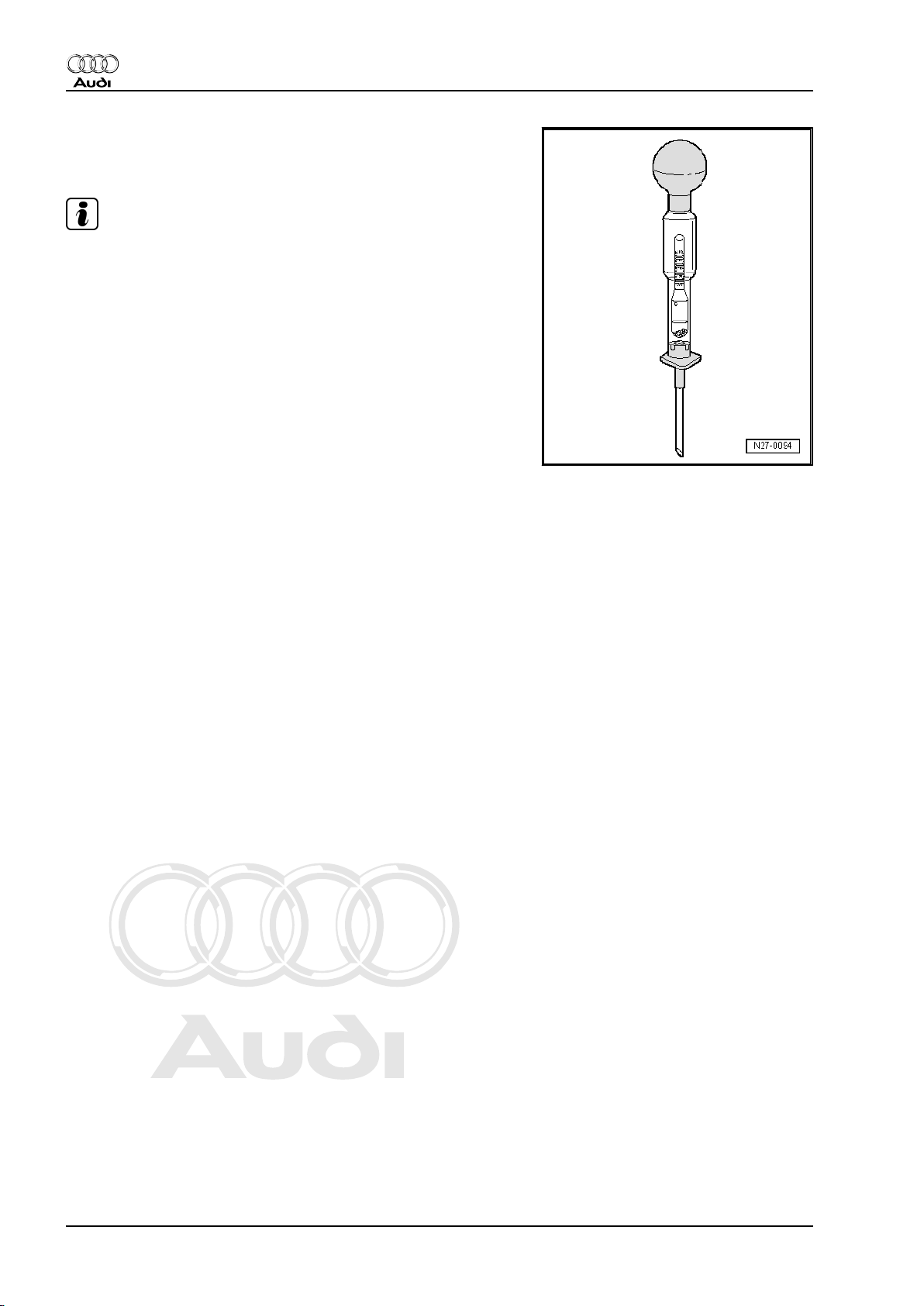
6.19 Hydraulic system: checking for leaks,
checking hydraulic fluid level and top‐
ping up if necessary
Fluid level in power steering system
• Fluid in cold condition:
– Do not start engine but bring front wheels to straight-ahead
position.
• Fluid at operating temperature (above approx. 50 °C):
– Start engine and bring front wheels to straight-ahead position.
– Use a screwdriver -arrow- to unscrew filler cap with dipstick.
– Clean dipstick with a clean cloth.
– Screw cap on hand tight and unscrew again.
34 6. Description of work
Page 39

Protected by copyright. Copying for private or commercial purposes, in part or in whole, is not
permitted unless authorised by AUDI AG. AUDI AG does not guarantee or accept any liability
with respect to the correctness of information in this document. Copyright by AUDI AG.
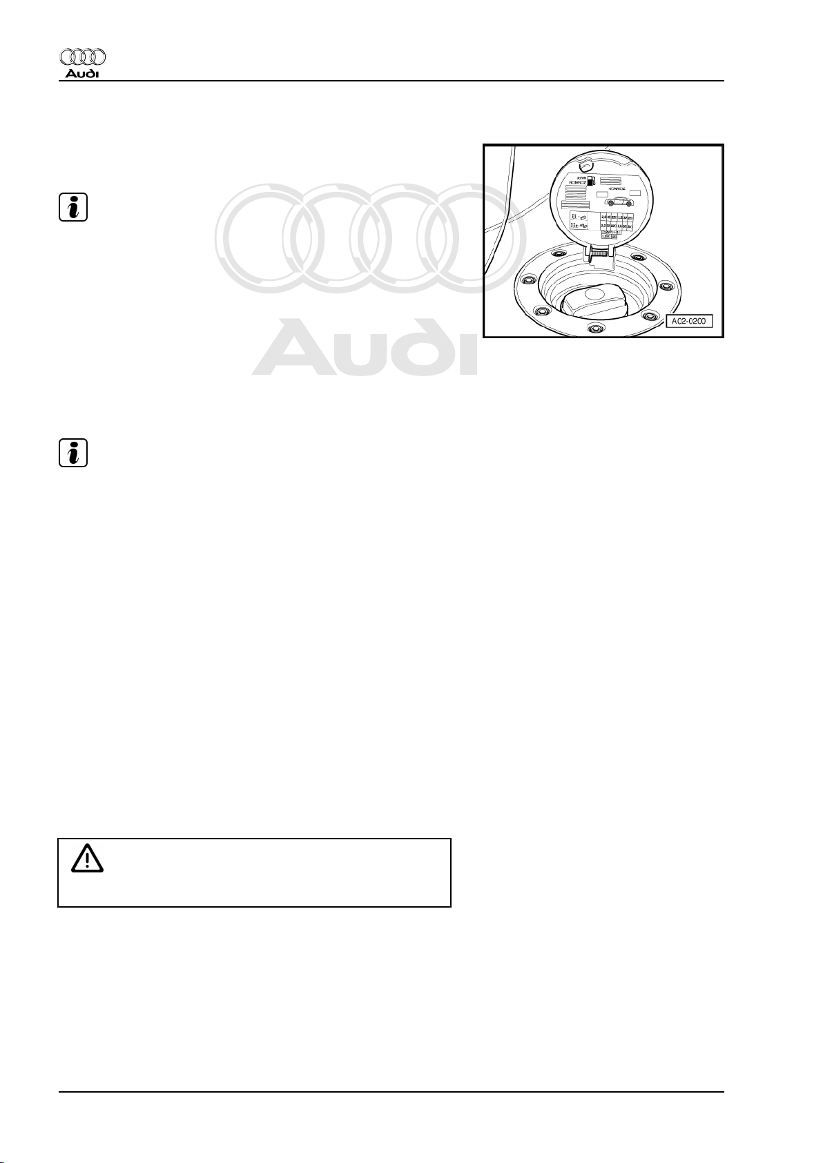
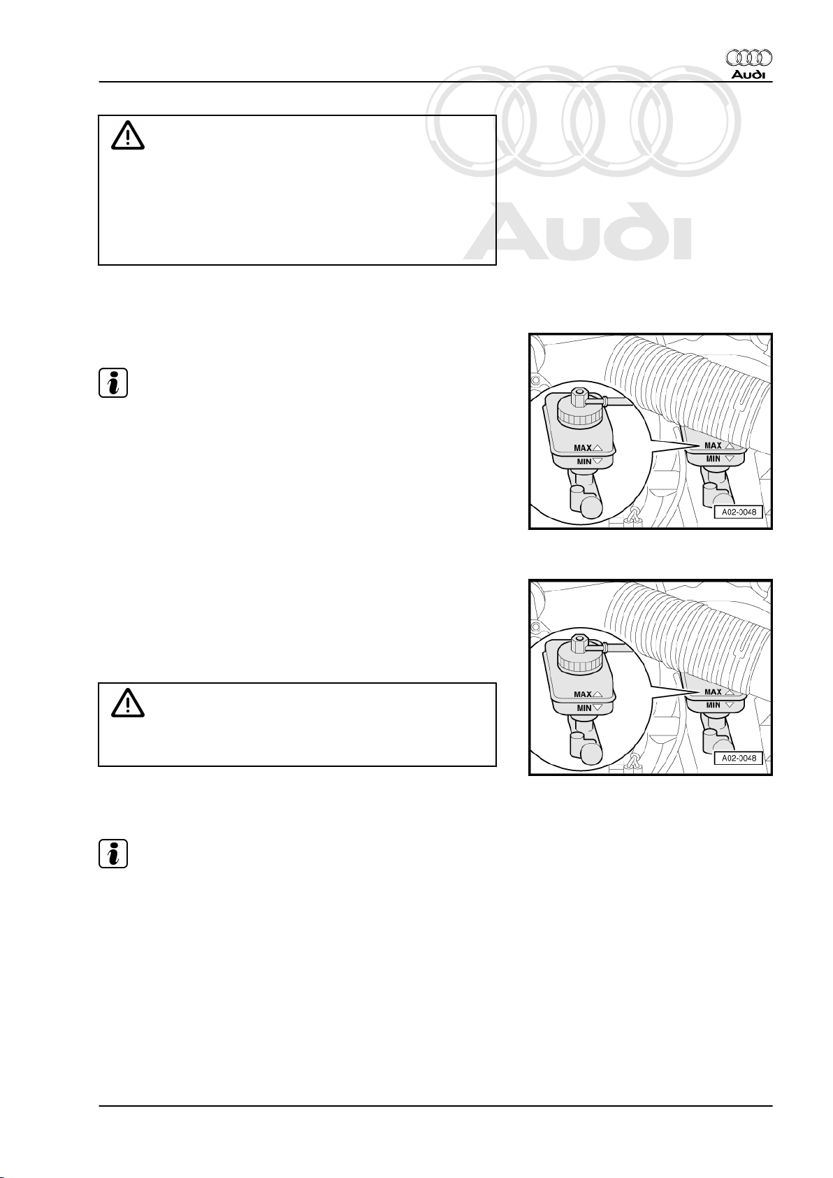
– Check fluid level:
• Fluid in cold condition:
The fluid level must be in area of MIN. marking (up to 2 mm above
or below marking).
• Fluid at operating temperature (above approx. 50 °C):
Fluid level must be between MIN. and MAX. markings.
Note
♦
The fluid level reading will only be accurate if the cap was
screwed on properly before checking the dipstick.
♦
If the fluid level is above the area specified, the excess fluid
must be extracted.
WARNING
If the fluid level is below the range specified, the hydraulic sys‐
tem must be checked for leaks (repair measure). It is then not
sufficient to merely top up the fluid.
Audi TT 1999 ➤
Maintenance - Edition 06.2007
– If the system is not leaking top up with “G 002 000” fluid.
– Screw cap on hand tight.
6.20 Instrument cluster: setting the language
Vehicles with Driver Information System (DIS)
When a car is delivered to the customer, the multifunction monitor
display can be set to any of the following languages as required:
German, English, French, Italian, Spanish, Portuguese
Cars are delivered by the factory with the multifunction monitor
set to German.
– To change the language proceed as follows:
Connect fault reader -V.A.G 1551- .
– ⇒ page 31
– Switch on ignition.
– Enter “1” for “Rapid data transfer”.
– Enter “17” to select the address word “Dash panel insert” and
confirm entry with Q key.
– Press → key twice to continue.
– Enter “10” to select the function “Adaption” and confirm entry
with Q key.
– Enter “04” to select “Adaption channel 04” and confirm entry
with Q key.
When the following is indicated on the display:
– Press → key to continue.
Indicated on display:
Channel 4 Adaption 2 ->
- ↑ - ↓ -
Channel 4 Adaption 2 Q
Enter adaption value XXXXX
6. Description of work 35
Page 40

Protected by copyright. Copying for private or commercial purposes, in part or in whole, is not
permitted unless authorised by AUDI AG. AUDI AG does not guarantee or accept any liability
with respect to the correctness of information in this document. Copyright by AUDI AG.
Audi TT 1999 ➤
Maintenance - Edition 06.2007
– Select desired language according to the following table.
Language version Code
German 00001
English 00002
French 00003
Italian 00004
Spanish 00005
Portuguese 00006
Note
♦
The first four digits must be “0”.
♦
If an incorrect value is entered the function “Adaption” will be
terminated automatically and must be restarted!
Example:
– Enter “00001” (e.g. for German).
When the following is indicated on the display:
Channel 4 Adaption 2 Q
Enter adaption value 00001
– Confirm entry with Q key.
When the following is indicated on the display:
– Confirm entry with Q key.
When the following is indicated on the display:
– Confirm entry with Q key.
When the following is indicated on the display:
– Terminate adaption of the language version by pressing the →
key.
Indicated on display:
6.21 Air conditioner: checking operation and setting temperature to 22 °C
– Check all air conditioner functions: ⇒ Owner's Manual
– Check whether display zone -2- is set to 22 °C.
– If necessary, adjust the temperature setting as follows:
– Press button -3- for automatic operation. “AUTO” will appear
in the display -2-.
– Turn switch -1- to the left (“colder”) or to the right (“warmer”)
to set temperature to 22 °C.
Channel 4 Adaption 1 Q
- ↑ - ↓ -
Channel 4 Adaption 1 Q
Store changed value?
Channel 4 Adaption 1 ->
Changed value is stored
Rapid data transfer HELP
Select function XX
36 6. Description of work
Page 41

Protected by copyright. Copying for private or commercial purposes, in part or in whole, is not
permitted unless authorised by AUDI AG. AUDI AG does not guarantee or accept any liability
with respect to the correctness of information in this document. Copyright by AUDI AG.
6.22 Cooling system: checking antifreeze and topping up with coolant if necessary
Note
♦
All new engines are filled with the coolant additive G 12 Plus
conforming to TL VW 774 F (purple colour). It is possible to
mix G 12 Plus with the previously used coolant additives G 11
and G 12 (red). However, please note that only G 12 Plus
should now be used for re-filling (in view of its improved prop‐
erties).
♦
G 12 Plus is suitable for filling cast iron and all-aluminium en‐
gines for life and provides the engine with ideal protection
against frost, corrosion damage, scaling and overheating.
♦
G 12 Plus raises the boiling point of the coolant to 135 °C and
improves heat dissipation.
♦
The antifreeze ratio must be at least 40 % (offers frost protec‐
tion down to -25 °C), but should not exceed 60 % (offers frost
protection down to -40 °C), as beyond this concentration the
antifreeze protection and also the cooling efficiency are re‐
duced again.
♦
Frost protection should be ensured down to temperatures of
about -25 °C.
Audi TT 1999 ➤
Maintenance - Edition 06.2007
Checking antifreeze and topping up with coolant additive if nec‐
essary
Special tools and workshop equipment required
♦ Refractometer -T10007-
Note
For exact readings for the following tests refer to the light-dark
border. Before carrying out the tests, you can first determine the
light-dark border for water. To do so, use a pipette to place a drop
of water on the glass. The light-dark border will now show up
clearly at the “WATERLINE” marking.
– Check the coolant additive concentration using the refractom‐
eter -T10007- . Observe the instructions in the operating man‐
ual.
6. Description of work 37
Page 42

Protected by copyright. Copying for private or commercial purposes, in part or in whole, is not
permitted unless authorised by AUDI AG. AUDI AG does not guarantee or accept any liability
with respect to the correctness of information in this document. Copyright by AUDI AG.
Audi TT 1999 ➤
Maintenance - Edition 06.2007
Scale -1- on the refractometer applies to coolant additives G 12,
G 12 Plus and G 11.
Scale -2- refers only to coolant additive -G 13- (previously called
L80).
Note
♦
Frost protection should be ensured down to temperatures of
about –25 °C.
♦
If greater antifreeze protection is required in very cold cli‐
mates, the proportion of G 12 Plus can be increased, but only
up to 60 % (this gives frost protection to about –40 °C). Beyond
this concentration the antifreeze protection and also the cool‐
ing efficiency are reduced again.
– If antifreeze protection is too low, drain off the required quantity
as specified in the frost protection table and top up with coolant
additive G 12 Plus.
Note
Observe disposal regulations.
Antifreeze protection to °C Required quantity in litres
Actual Specified 4-cyl. engines 6-cyl. engines
0 -25 3.5 5.0
-35 4.0 6.0
-5 -25 3.0 4.5
-35 3.5 5.5
-10 -25 2.0 3.5
-35 3.0 4.5
-15 -25 1.5 2.5
-35 2.0 3.5
-20 -25 1.0 1.5
-35 1.5 2.5
-25 -35 1.0 1.5
-30 -35 0.5 1.0
-35 -40 0.5 0.5
– Check coolant additive concentration once more following
road test.
Checking coolant level and topping up with coolant if necessary
– Check coolant level on expansion tank while the engine is
cold.
38 6. Description of work
Page 43

Protected by copyright. Copying for private or commercial purposes, in part or in whole, is not
permitted unless authorised by AUDI AG. AUDI AG does not guarantee or accept any liability
with respect to the correctness of information in this document. Copyright by AUDI AG.
♦ Delivery Inspection: Coolant level should be above “Min.”
marking -arrow-
♦ Inspection Service: Coolant level should be above “Min.”
marking -arrow-
– If coolant level is too low, add required amount (using correct
mixture ratio).
Note
If fluid losses are greater than can be reasonably expected, de‐
termine the cause and rectify faults (repair measure).
Mixture ratio:
Audi TT 1999 ➤
Maintenance - Edition 06.2007
Frost protectiontoCoolant additive
Water
G 12 Plus /
TL VW 774 F
-25 °C approx. 40 % approx. 60 %
-35 °C approx. 50 % approx. 50 %
-40 °C approx. 60 % approx. 40 %
Note
♦
The coolant additive G 12 Plus conforming to specification
"TL VW 774 F" prevents frost and corrosion damage, stops
scaling and at the same time raises the boiling point of the
coolant. It is therefore essential to use the correct antifreeze
and corrosion protection additive in the cooling system all year
round.
♦
Because of its high boiling point, the coolant improves engine
reliability under heavy loads, particularly in countries with trop‐
ical climates.
♦
The coolant concentration must not be reduced by adding wa‐
ter even in warmer seasons and in warmer countries. The
antifreeze ratio must be at least 40 %.
6.23 Poly V-belt: renewing
⇒ 4-cyl. engine, mechanics; Repair group 13; Crankshaft group;
Removing and installing poly V-belt
⇒ 6-cyl. engine, mechanics; Repair group 13; Crankshaft group;
Removing and installing poly V-belt
6. Description of work 39
Page 44

Protected by copyright. Copying for private or commercial purposes, in part or in whole, is not
permitted unless authorised by AUDI AG. AUDI AG does not guarantee or accept any liability
with respect to the correctness of information in this document. Copyright by AUDI AG.
Audi TT 1999 ➤
Maintenance - Edition 06.2007
6.24 Air cleaner: cleaning housing and re‐
newing filter element
4-cyl. and 6-cyl. petrol engines:
– Detach the connector -1- from the air mass meter.
– Slacken bolts -2- and lift cover off air cleaner housing.
– Remove old filter element.
– Clean filter housing and install new filter element.
Note
♦
If the air filter element is very dirty or soaked with water, dirt
particles or moisture can reach the air mass meter -G70- and
falsify the detected air mass values. This will cause a loss of
power, as the calculated injection quantities will be too low.
♦
Always use genuine air filter elements (same as original equip‐
ment).
♦
Use a lubricant (silicon-free!) when installing the intake hose.
♦
Secure all hose connections with genuine hose clips: ⇒ Parts
catalogue
♦
Clean the water drain in the bottom section of the air cleaner
housing with compressed air.
♦
Clean the water drain in the bottom section of the air cleaner
housing with compressed air.
♦
Clean the air cleaner housing (top and bottom sections) to re‐
move any salt residue, dirt and leaves (if necessary vacuumclean).
♦
Check air mass meter and air intake hose (clean air side) for
salt residue, dirt and leaves.
♦
Check intake duct as far as air filter element for dirt.
♦
When installing the air filter element make sure it is positioned
centrally on the mounting in the bottom section of the air
cleaner.
♦
Carefully fit the top section of the air cleaner on the bottom
section of the air cleaner, without applying any force. When
fitting the top section of the air cleaner, make sure it is NOT
positioned on the air filter element at an angle. Note position
of sealing lip on air filter element (to prevent air leaks).
♦
Then secure top section of air cleaner to bottom section.
40 6. Description of work
Page 45

Protected by copyright. Copying for private or commercial purposes, in part or in whole, is not
permitted unless authorised by AUDI AG. AUDI AG does not guarantee or accept any liability
with respect to the correctness of information in this document. Copyright by AUDI AG.
6.25 Bonnet arrester hook: lubricating
– Only grease the bonnet arrester hook at the points shown in
the illustration -arrows-.
♦ Lubricant: “G 052 778 A2”
6.26 Engine cover panel: removing
– Loosen nuts -arrows- and remove engine cover.
4-cylinder petrol engines: 132 kW
Audi TT 1999 ➤
Maintenance - Edition 06.2007
4-cylinder petrol engines: 165 kW / 176 kW
6.27 Engine (from above and below) and en‐
gine compartment: visual check for
leaks and damage
– Carry out visual check as follows:
– Remove engine cover panel ⇒ page 41 .
– Check engine and engine compartment for leaks and damage.
– Check the pipes, hoses and connections of the following sys‐
tems for leaks, chafing, porosity and brittleness.
♦ Fuel system
♦ Cooling and heating system
♦ Brake system
6. Description of work 41
Page 46

Protected by copyright. Copying for private or commercial purposes, in part or in whole, is not
permitted unless authorised by AUDI AG. AUDI AG does not guarantee or accept any liability
with respect to the correctness of information in this document. Copyright by AUDI AG.
Audi TT 1999 ➤
Maintenance - Edition 06.2007
– Perform a visual check of the same components from below
with the vehicle raised on a lifting platform and the noise in‐
sulation removed.
WARNING
Any faults found must be rectified (repair measure).
6.28 Engine oil: draining or extracting, chang‐
ing oil filter
Note
Oil should always be changed when engine is warm.
Special tools required
♦ Hazet strap wrench -2171-1-
or
42 6. Description of work
Page 47

Protected by copyright. Copying for private or commercial purposes, in part or in whole, is not
permitted unless authorised by AUDI AG. AUDI AG does not guarantee or accept any liability
with respect to the correctness of information in this document. Copyright by AUDI AG.
♦ Oil filter tool -3417-
♦ Oil extractor -V.A.G 1782-
Note
Observe disposal regulations.
4-cylinder petrol engines:
– Remove noise insulation ⇒ page 33 .
– Use Hazet strap wrench -2171-1- or oil filter tool -3417- to
slacken oil filter and then remove it.
– Open oil drain plug / draw off engine oil.
– Clean sealing surface for oil filter at engine.
– Lightly lubricate rubber seal.
– Screw in new filter and tighten.
WARNING
Audi TT 1999 ➤
Maintenance - Edition 06.2007
After renewing oil filter cartridge, check clearance of hoses
from oil cooler to adjacent components, if necessary correct oil
cooler position.
– Screw in oil drain plug with new seal.
Tightening torque Nm
Oil drain plug 30
Note
♦
Fill up with engine oil ⇒ page 44 .
♦
Please observe the notes for turbocharged engines
⇒ page 44 .
6-cylinder petrol engine
– Remove noise insulation before draining oil via the oil drain
plug ⇒ page 33 .
6. Description of work 43
Page 48

Protected by copyright. Copying for private or commercial purposes, in part or in whole, is not
permitted unless authorised by AUDI AG. AUDI AG does not guarantee or accept any liability
with respect to the correctness of information in this document. Copyright by AUDI AG.
Audi TT 1999 ➤
Maintenance - Edition 06.2007
– Drain oil via drain plug -1-.
Note
Observe disposal regulations.
– Loosen lower part of filter -3- on hexagon -2- or on circumfer‐
ence -4- and remove.
– Remove old filter element.
– Wipe filter housing with a cloth.
– Remove old O-ring.
– Use new O-ring and moisten with oil.
– Install new filter element and new O-ring.
– Tighten lower part of filter -3- on hexagon -2- to 30 Nm.
– Fit new seal to drain plug -1- and tighten to 10 Nm.
Tightening torque Nm
Oil drain plug 30
Note
Fill up with engine oil ⇒ page 44 .
6.29 Engine oil: filling up
Note
Please observe the engine oil capacities and oil grades listed in
the ELSA maintenance table.
Engines with turbocharger:
– When the engine oil and oil filter have been changed, it is im‐
portant to note the following after starting the engine for the
first time:
♦ The engine must only run at idling speed as long as the oil
pressure warning lamp in dash panel is on. Do not rev up! If
the engine is revved up the turbocharger can be damaged or
fail completely.
♦ The full oil pressure is not attained until the warning lamp has
gone out, only then can the engine be revved up.
All models:
– Finally, check engine oil level ⇒ page 45 .
44 6. Description of work
Page 49

Protected by copyright. Copying for private or commercial purposes, in part or in whole, is not
permitted unless authorised by AUDI AG. AUDI AG does not guarantee or accept any liability
with respect to the correctness of information in this document. Copyright by AUDI AG.
6.30 Engine: checking oil level
Note
♦
Engine oil temperature at least 60 °C.
♦
Vehicle must be level (horizontal).
♦
Wait a few minutes after switching off the engine to allow the
oil to flow back into the sump.
– Pull out the dipstick, wipe with a clean cloth and insert again
as far as it will go.
– Pull out the dipstick again and read off the oil level.
Markings on oil dipstick:
a - Do not top up oil.
b - Oil can be topped up. The oil level may rise as far as area
-a- after topping up.
c - Oil must be topped up. The oil level is sufficient if it is some‐
where in area -b- (grooved area) after topping up.
Audi TT 1999 ➤
Maintenance - Edition 06.2007
Note
The oil level must not be above marking -a- on the dipstick.
6.31 Road test
To what extent the following can be checked depends on vehicle
equipment and local conditions (urban/country).
– The following points must be checked during the road test:
♦ Engine: performance, misfiring, idling speed, acceleration
♦ Clutch: pulling away, pedal pressure, odours
♦ Gear selection: ease of operation, gear lever position
♦ Brake pedal and handbrake: operation, travel and effective‐
ness, pulling to one side, juddering, squeal
♦ ABS function: pulsing must be felt at brake pedal when per‐
forming ABS-controlled braking.
♦ Steering: operation, steering free play, steering wheel central‐
ised when wheels are in straight-ahead position.
♦ Cruise control system: operation
♦ Radio: quality of reception, GALA, interference
♦ Driver Information System (DIS): functions
♦ Air conditioner: operation
♦ Vehicle: moving off line when travelling straight ahead (level
road)
♦ Imbalance: wheels, drive shafts
♦ Wheel bearings: noises
♦ Engine: hot starting behaviour
6. Description of work 45
Page 50

Protected by copyright. Copying for private or commercial purposes, in part or in whole, is not
permitted unless authorised by AUDI AG. AUDI AG does not guarantee or accept any liability
with respect to the correctness of information in this document. Copyright by AUDI AG.
Audi TT 1999 ➤
Maintenance - Edition 06.2007
6.32 Wheel bolts: tightening to specified tor‐
que
Trim cap
Puller -A- for removing trim caps is included in vehicle tool kit.
Wheel bolts
The adapter for loosening and tightening anti-theft wheel bolts is
included in vehicle tool kit.
Note
Ensure that wheel bolts are tightened in diagonal sequence to the
following tightening torque:
Tightening torque Nm
Wheel bolts 120
– Place puller and adapter back in vehicle tool kit after complet‐
ing work.
6.33 Tyre repair kit: checking
In the case of vehicles with a tyre repair set, the expiry date
-arrow- must be checked.
Please note:
The bottle must be replaced if the expiry date has been exceeded.
6.34 Radio (Chorus, Concert): switching off transport mode
Transport mode for the aforementioned radios was activated on
vehicles built from week 18 (gradual introduction).
The calendar week in which the vehicle was built is shown in the
seven-digit production control number on the data sticker (see
end of line “2”). The first two digits of the production control num‐
ber “arrow” indicate the week.
Transport mode may have been activated in “dash panel insert
17” and “Radio 56”.
– To deactivate the transport mode (e.g. in dash panel insert
“address word 17”) follow the instructions shown below.
To deactivate the transport mode for radio “address word 56” fol‐
low the same procedure.
♦ Connect vehicle diagnostic, testing and information system -
VAS 5051- ⇒ page 70 .
– Switch on ignition.
46 6. Description of work
Page 51

Protected by copyright. Copying for private or commercial purposes, in part or in whole, is not
permitted unless authorised by AUDI AG. AUDI AG does not guarantee or accept any liability
with respect to the correctness of information in this document. Copyright by AUDI AG.
Indicated on display:
Selecting operating mode:
– Press button for “Vehicle self-diagnosis” on display.
Note
If the display does not coincide with the work sequence shown:
⇒ Operating instructions for Vehicle Diagnostic, Testing and In‐
formation System VAS 5051.
Indicated on display:
Selecting vehicle system:
– Press “17 - Dash panel insert” on display -arrow-.
Audi TT 1999 ➤
Maintenance - Edition 06.2007
Indicated on display:
The control unit identification and coding are displayed -arrow-.
– Press arrow button -1- on the display.
Indicated on display:
– Press “10 - Adaption” on display -arrow-.
6. Description of work 47
Page 52

Protected by copyright. Copying for private or commercial purposes, in part or in whole, is not
permitted unless authorised by AUDI AG. AUDI AG does not guarantee or accept any liability
with respect to the correctness of information in this document. Copyright by AUDI AG.
Audi TT 1999 ➤
Maintenance - Edition 06.2007
Indicated on display:
– On the number block of the display -arrow- press key 9 twice.
The transport mode is activated or deactivated in adaption chan‐
nel 99
– Press Q key on display number block to confirm entry.
Note
♦
“0” transport mode off
♦
“1” transport mode on
Indicated on display:
– Move the cursor -arrow- on the display to the left until "0" is
displayed above the scroll bar -1-.
♦ "0" transport mode off
– Press “Save” button -2- on the display.
Indicated on display:
– Press “Transfer” button on display -arrow-.
Ending output
Indicated on display:
– Press “Go to” button on display -arrow-.
48 6. Description of work
Page 53

Protected by copyright. Copying for private or commercial purposes, in part or in whole, is not
permitted unless authorised by AUDI AG. AUDI AG does not guarantee or accept any liability
with respect to the correctness of information in this document. Copyright by AUDI AG.
Indicated on display:
– Press “Exit” button on display -arrow-.
– Press “Exit” button in the Exit menu.
– Switch off ignition.
Note
The -VAS 5051- must remain connected for various checks and
for carrying out the exhaust emissions test (if required).
6.35 Radio: activating anti-theft coding by en‐
tering fixed code number
The radio units are supplied with a fixed code. This means that
each radio unit with anti-theft coding is programmed with its own
code number. The fixed code is not activated by the factory.
The security coding of the ready-to-use unit is only activated by
entering the fixed code.
– Activate the fixed code as follows:
“Chorus” and “Concert” radios:
– Switch on radio.
– Press buttons TP and RDS simultaneously until “1000” ap‐
pears in the digital display. Release the buttons.
New generation of radios
– Press buttons RDS and SCAN simultaneously until “1000” ap‐
pears in the digital display. Release the buttons.
All models:
– Use radio station buttons 1 to 4 to enter the code number which
appears on the adhesive radio code card. Button 1 is used to
enter the first digit of the code number, button 2 for the second
digit, and so on.
– Then press buttons TP and RDS simultaneously again and
hold down until “SAFE” appears on the frequency display.
(New radio generation: press buttons RDS and SCAN.) Re‐
lease the buttons. After a brief delay a frequency will appear
automatically.
Audi TT 1999 ➤
Maintenance - Edition 06.2007
6.36 Dust and pollen filter: renewing
The filter is located below the plenum chamber cover (right-side).
– Pull rubber seal off upwards to vehicle centre.
– Fold up movable part -A- of plenum chamber cover.
– Press back the 2 retainer tabs -B- (one of the retainer tabs is
concealed in illustration).
– Remove dust and pollen filter -C-.
6. Description of work 49
Page 54

Protected by copyright. Copying for private or commercial purposes, in part or in whole, is not
permitted unless authorised by AUDI AG. AUDI AG does not guarantee or accept any liability
with respect to the correctness of information in this document. Copyright by AUDI AG.
Audi TT 1999 ➤
Maintenance - Edition 06.2007
Note
♦
Observe disposal regulations.
♦
Plenum chamber cover and cowl panel trim must be properly
installed to make sure no water can run into the dust and pollen
filter or the heating system.
♦
The dust and pollen filter element must be fitted into the frame
-B- facing in the correct direction. The arrow markings -A- in‐
dicate the direction of air flow.
– Install new filter element.
– Install plenum chamber cover and rubber seal.
6.37 Manual gearbox/final drive: checking oil level, topping up with oil if necessary
⇒ Manual gearbox, selector mechanism assembly, differential
lock; Rep. Gr. 34 ; Checking gear oil
6.38 Windscreen wiper/washer system and headlight washer system: checking jet settings and operation
Note
If the functional check shows that the wiper blades judder or make
noises, check wiper blade setting angle ⇒ page 58 .
6.39 Windscreen wiper/washer system: checking jet settings, adjusting jets if necessary
Note
Never use pins or other sharp objects as these will damage the
fan jets.
Windscreen washer jet settings
– Mark upper edge of spray area on the windscreen with water-
soluble pen.
– Use a screwdriver to adjust height of spray area on fan jet -
arrow-.
Note
The setting dimension is measured starting from fan jet.
50 6. Description of work
Page 55

Protected by copyright. Copying for private or commercial purposes, in part or in whole, is not
permitted unless authorised by AUDI AG. AUDI AG does not guarantee or accept any liability
with respect to the correctness of information in this document. Copyright by AUDI AG.
Setting dimension:
a = 400 mm
6.40 Headlight washer system: checking jet settings
The headlight washer jets are set by the manufacturer and there‐
fore do not need to be adjusted.
6.41 Headlights: checking settings and ad‐
justing if necessary
Audi TT 1999 ➤
Maintenance - Edition 06.2007
The following checking and adjustment procedures apply to all
countries. However, national legislation and guidelines for indi‐
vidual countries must be adhered to.
6.41.1 Requirements for checking and adjust‐
ing
♦ Tyre pressures OK.
♦ Lenses must not be damaged or dirty.
♦ Reflectors and bulbs OK.
♦ Vehicle correctly loaded.
Loading: With one person or 75 kg on the driver's seat and the
vehicle otherwise unloaded (unladen weight).
The unladen weight is the weight of the vehicle ready for operation
with full fuel tank (at least 90 %) including the weight of all equip‐
ment normally carried (e.g. spare wheel, tools, jack, fire extin‐
guisher, etc.).
If the fuel tank is not at least 90% full put in additional weight as
follows:
– Read fuel level in fuel tank from the fuel gauge. Calculate ad‐
ditional weight according to the following table and place
weight into boot.
6.41.2 Capacity table
Fuel level on fuel
gauge
1/4 40 45
1/2 25 30
3/4 10 15
full 0 0
Example:
When the tank is half full an additional weight of 25 kg must be
placed in the boot if the vehicle is front-wheel drive.
Front-wheel drive
Additional weight in
kg
Four-wheel drive
Additional weight in
kg
6. Description of work 51
Page 56

Protected by copyright. Copying for private or commercial purposes, in part or in whole, is not
permitted unless authorised by AUDI AG. AUDI AG does not guarantee or accept any liability
with respect to the correctness of information in this document. Copyright by AUDI AG.
Audi TT 1999 ➤
Maintenance - Edition 06.2007
Note
As an additional weight it is best to use a fuel canister filled with
water (a 5 litre fuel canister filled with water weighs approx. 5 kg).
Roll vehicle several metres or depress front and rear springs fully
several times so that springs settle correctly.
♦ Vehicle and headlight adjuster must be on a level surface ⇒
Headlight adjuster operating instructions .
♦ Vehicle and headlight adjuster must be aligned.
Ensure that the headlight adjuster is positioned 30 cm in front of
the headlight.
A “%” value is marked on top of headlight. This indicates the dip
setting that the headlights must be adjusted to. The percentage
value is for a range of 10 m. At a dip setting of, for example, 1.0%
(for vehicles with headlight range control), this converts to 10 cm.
♦ Dip setting must be adjusted.
Dip setting:
♦ Headlights (main and dipped beam) 10 cm
Vehicles with headlight range control:
♦ The knurled wheel for headlight range control must be in po‐
sition -0-.
6.41.3 Checking headlight setting (using new test screen without 15° setting line)
– Check the following:
♦ With dipped beam switched on, the horizontal light-dark bor‐
der should coincide with the setting line -1- on the test surface.
♦ The break-away point -2- between the horizontal section of the
light-dark border on the left and the rising section on the right
should coincide with the vertical line running through the cen‐
tral point -3-. The bright spot in the centre of the beam should
be to the right of the vertical line.
Note
♦
To make it easier to find break-away point -2-, cover and un‐
cover left half of headlight (as seen in direction of travel) a few
times. Then check dipped beam again.
♦
If dipped beams have been adjusted correctly the centre point
of the main beam should lie on central point -3-.
♦
If using an old test screen with a 15 ° setting line, the adjust‐
ment procedure is the same as for the new test screen. To
avoid incorrect settings, ignore the 15 ° setting line.
52 6. Description of work
Page 57

Protected by copyright. Copying for private or commercial purposes, in part or in whole, is not
permitted unless authorised by AUDI AG. AUDI AG does not guarantee or accept any liability
with respect to the correctness of information in this document. Copyright by AUDI AG.
6.41.4 Adjusting headlights
– Gas discharge headlights ⇒ page 53
– Halogen headlights ⇒ as described below
Headlight (left)
– Adjust setting using a suitable screwdriver (do not damage
adjuster wheel) or hexagon key.
2 - Height adjuster screw
3 - Adjuster screw for lateral setting
– Use a cross-head screwdriver or hexagon key to reset adjuster
screw accordingly.
Note
On the right headlight, the adjuster screws are in a symmetrically
opposite position.
Fog lights:
– Check whether the upper light-dark border touches the setting
line horizontally over the complete width of the test screen.
Audi TT 1999 ➤
Maintenance - Edition 06.2007
Rapid data transfer HELP
Enter address word XX
Note
The height of the fog lights can be adjusted by means of adjuster
screw -1-.
6.41.5 Adjusting headlights with automatic headlight range control
• Note the requirements for checking and adjusting ⇒ page 51
• Basic setting with -VAS 5051- ⇒ page 55
• Basic setting with -V.A.G 1551- ⇒ as described below
– Connect -V.A.G 1551- ⇒ page 31 .
– Switch on ignition.
– Press key 1 for “Rapid data transfer” mode.
Indicated on display:
Address word for automatic headlight range control: 55
– Press key 5 twice.
Rapid data transfer Q
55 - Headlight range control
Indicated on the display:
– Confirm entry with Q key.
6.41.6 Perform basic setting:
– Press keys 0 and 4. (04 selects “Basic setting” function).
Indicated on the display:
Rapid data transfer Q
04 - Basic setting
Basic setting
Input display group number XXX
6. Description of work 53
Page 58

Protected by copyright. Copying for private or commercial purposes, in part or in whole, is not
permitted unless authorised by AUDI AG. AUDI AG does not guarantee or accept any liability
with respect to the correctness of information in this document. Copyright by AUDI AG.
Audi TT 1999 ➤
Maintenance - Edition 06.2007
– Confirm entry with Q key.
Indicated on the display:
– Enter display group number 001.
– Confirm entry with Q key.
Indicated on the display:
– The headlights will now be moved into setting position (approx.
15 seconds).
Indicated on the display:
– The headlights are now in the setting position. Adjust head‐
lights with headlight adjustment device (e.g. -VAS 5046- ).
Basic setting function 1 switches off automatic range control
and fault “Headlights not set” will be stored in fault memory.
– Press → key.
Indicated on display:
– Press keys 0 and 4. (04 selects “Basic setting” function).
Indicated on the display:
– Confirm entry with Q key.
System in basic setting 1 ->
Wait
System in basic setting 1 ->
Set headlight
Rapid data transfer HELP
Select function XX
Rapid data transfer Q
04 - Basic setting
Basic setting
Input display group number XXX
Indicated on the display:
– Enter display group number 002.
– Confirm entry with Q key.
Indicated on the display:
– The control unit has now "learnt" this position as reference
position. The fault “Headlights not set” in the fault memory will
be erased and the automatic range control function will be re‐
stored.
– Press → key.
Indicated on display:
– Press keys 0 and 2. (02 selects “Interrogate fault memory”
function).
Indicated on display:
– Confirm entry with Q key.
The display shows either no fault or the number of faults that have
been stored.
– Press → key.
System in basic setting 2 ->
Ctrl pos. learnt
Rapid data transfer HELP
Select function XX
Rapid data transfer Q
02 - Interrogate fault memory
X faults recognised!
Indicated on display:
– Press keys 0 and 6. (06 selects “End output” function).
54 6. Description of work
Rapid data transfer HELP
Select function XX
Page 59

Protected by copyright. Copying for private or commercial purposes, in part or in whole, is not
permitted unless authorised by AUDI AG. AUDI AG does not guarantee or accept any liability
with respect to the correctness of information in this document. Copyright by AUDI AG.
6.41.7 Performing basic setting using vehicle
diagnostic, testing and information sys‐
tem -VAS 5051- :
– Connect the vehicle diagnostic, testing and information sys‐
tem -VAS 5051- ⇒ page 70 .
– Switch on ignition.
Indicated on display:
Audi TT 1999 ➤
Maintenance - Edition 06.2007
6.41.8 Selecting operating mode:
– Press button for “vehicle self-diagnosis” on display -arrow-.
Note
If the display does not coincide with the work sequence shown:
⇒ Operating instructions for Vehicle Diagnostic, Testing and In‐
formation System VAS 5051.
Indicated on display:
– Press “55 - Headlight range control” on display -arrow-.
Indicated on display:
– Press “04 - Start basic setting” on display -arrow-.
6. Description of work 55
Page 60

Protected by copyright. Copying for private or commercial purposes, in part or in whole, is not
permitted unless authorised by AUDI AG. AUDI AG does not guarantee or accept any liability
with respect to the correctness of information in this document. Copyright by AUDI AG.
Audi TT 1999 ➤
Maintenance - Edition 06.2007
Indicated on display:
– On the number block of the display -arrow- press 001 (001
selects “display group number 001”).
– Press Q key on display number block to confirm entry.
After the message “wait”, the following display will appear:
Indicated on display:
– Adjust headlights now ⇒ page 53
– After adjusting the headlights, press the -arrow- key on the
display.
Indicated on display:
– On the number block of the display -arrow- press 002 (002
selects “display group number 002”).
– Press Q key on display number block to confirm entry.
Indicated on display:
The control unit then “learns” the reference position of the head‐
lights.
– Press -arrow- button on display.
56 6. Description of work
Page 61

Protected by copyright. Copying for private or commercial purposes, in part or in whole, is not
permitted unless authorised by AUDI AG. AUDI AG does not guarantee or accept any liability
with respect to the correctness of information in this document. Copyright by AUDI AG.
Indicated on display:
– Press -arrow- button on display.
Indicated on display:
– Press “02 - Interrogate fault memory” -arrow- on the display.
Audi TT 1999 ➤
Maintenance - Edition 06.2007
Indicated on display:
Any system faults that are stored will be displayed.
If faults have been stored these must be rectified. The fault log is
required for the repair work.
– Press -arrow- button on display.
Indicated on display:
– Press “Go to” button on display -arrow-.
6. Description of work 57
Page 62

Protected by copyright. Copying for private or commercial purposes, in part or in whole, is not
permitted unless authorised by AUDI AG. AUDI AG does not guarantee or accept any liability
with respect to the correctness of information in this document. Copyright by AUDI AG.
Audi TT 1999 ➤
Maintenance - Edition 06.2007
Indicated on display:
– Press “Exit” button on display -arrow-.
– Press “Exit” button in the Exit menu.
– Switch off ignition and detach diagnostic connector.
6.42 Windscreen and headlight washer sys‐
tem: topping up with washer fluid
– Fill container up to top with washer fluid.
Note
The washer fluid must always contain a pH-neutral window clean‐
ing additive (antifreeze additive in winter).
6.43 Wiper blades: checking park position and checking for damage
Park position for windscreen wiper blades
– Switch windscreen wipers on and off and let them return to
their park position.
– Check for the following distances between tips of wiper blades
-1- and plenum chamber cover -2- at bottom edge of wind‐
screen:
– Distance a = 15 ... 25 mm
Note
The layout is symmetrically opposite for right-hand drive vehicles.
– If necessary, loosen the wiper arm, align and tighten securing
nut.
– Actuate touch-wipe switch and check settings.
Tightening torque Nm
Wiper arms to wiper shafts 16
Setting angle of wiper blades
Note
Only check the setting angle if the wiper blades judder or make
noises.
Special tools and workshop equipment required
♦ Wiper arm setting tool -3358 B-
58 6. Description of work
Page 63

Protected by copyright. Copying for private or commercial purposes, in part or in whole, is not
permitted unless authorised by AUDI AG. AUDI AG does not guarantee or accept any liability
with respect to the correctness of information in this document. Copyright by AUDI AG.
– Switch windscreen wipers on and off and let them return to
their park position.
– Remove wiper blade.
– Insert wiper arm -2- into wiper arm setting tool -3358 B- and
secure with locking screw -3-.
– Compare angle indicated to value specified in table.
Setting angle (specifications)
Driver's side - 4°
Passenger's side - 4.5°
Tolerance - 1.5°
– If necessary, adjust the setting angle to the specified value as
follows:
– Apply open-end spanner (24 mm) -1- to setting tool and adjust
wiper arm -2- to specified value -arrows-.
– Release wiper arm -2- from setting tool and then re-secure
with locking screw -3-.
– Check that value is set according to the table. If necessary,
repeat setting and checking procedure until setting angle
meets specification.
– Remove setting tool and fit wiper blade.
– Check wiper system operates without juddering.
Audi TT 1999 ➤
Maintenance - Edition 06.2007
6.44 Service interval display: resetting In‐
spection Service (fixed intervals), up to
chassis No. 8NY1 049 999
Resetting service interval display with
♦ Vehicle diagnostic, testing and information system -VAS 5051-
⇒ page 61 .
or with the
♦ Fault reader -V.A.G 1551- as described below.
or
♦ without fault reader -V.A.G 1551- or vehicle diagnostic, testing
and information system -VAS 5051- ⇒ page 64 .
Connecting fault reader -V.A.G 1551- :
– Storage compartment on driver's side (bottom left)
6. Description of work 59
Page 64

Protected by copyright. Copying for private or commercial purposes, in part or in whole, is not
permitted unless authorised by AUDI AG. AUDI AG does not guarantee or accept any liability
with respect to the correctness of information in this document. Copyright by AUDI AG.
Audi TT 1999 ➤
Maintenance - Edition 06.2007
– Connect fault reader -V.A.G 1551- with lead -V.A.G 1551/3-
(ignition must be switched off).
– Switch on printer with PRINT button (indicator lamp in button
lights up).
Indicated on display:
V.A.G - SELF-DIAGNOSIS HELP
1 - Rapid data transfer
V.A.G - SELF-DIAGNOSIS HELP
2 - Flash code output
5) appears alternately
– Enter “1” for “Rapid data transfer”.
Indicated on display:
Rapid data transfer HELP
Select function XX
– Enter address word “17” for the “dash panel insert”.
– Confirm entry with Q key.
Rapid data transfer HELP
Address word 17
– Press keys 1 and 0 and confirm with the Q key.
Indicated on display:
Rapid data transfer Q
10 - Adaption
– Confirm entry with Q key.
Indicated on the display:
Adaption
Enter channel no. XX
– Press keys 0 and 2.
– Confirm entry with Q key.
Channel 2 Adaption 1 ->
1 - means that Service is active, i.e. the instrument cluster display
shows “SERVICE!”.
Note
The service interval display must only be reset by direct numerical
input.
– Press → key.
Indicated on the display:
Channel 2 Adaption 1
Enter adaption value XXXXX
The Service is reset by entering the following adaption values:
Adaption value Service setting
00000 Resetting
60 6. Description of work
Page 65

Protected by copyright. Copying for private or commercial purposes, in part or in whole, is not
permitted unless authorised by AUDI AG. AUDI AG does not guarantee or accept any liability
with respect to the correctness of information in this document. Copyright by AUDI AG.
– Use the keypad to enter the correct adaption value -00000- to
delete the service.
– Press key "0" five times.
Indicated on the display:
Channel 2 Adaption 1 Q
Enter adaption value 00000
– Confirm entry with Q key.
Indicated on the display:
Channel 2 Adaption 0 Q
0 - means that the Service has been reset, i.e. the instrument
cluster display will show “SERVICE IN 15000 km” once the entry
has been confirmed with the Q key.
– Confirm entry with Q key.
Indicated on the display:
Channel 2 Adaption 0 Q
Store changed value?
Audi TT 1999 ➤
Maintenance - Edition 06.2007
– Confirm entry with Q key.
Indicated on the display:
Channel 2 Adaption 0 ->
Changed value is stored
– Press → key to complete resetting of service interval display.
6.44.1 Resetting the service interval display (VAS 5051)
Special tools and workshop equipment required
♦ Vehicle diagnostic, testing and information system -VAS 5051-
♦ Adapter lead -VAS 5051/5a-
Connecting vehicle diagnostic, testing and information system VAS 5051-
– Apply handbrake.
– Manual gearbox: gear lever in neutral.
With ignition switched off, connect -VAS 5051- as follows:
6. Description of work 61
Page 66

Protected by copyright. Copying for private or commercial purposes, in part or in whole, is not
permitted unless authorised by AUDI AG. AUDI AG does not guarantee or accept any liability
with respect to the correctness of information in this document. Copyright by AUDI AG.
Audi TT 1999 ➤
Maintenance - Edition 06.2007
– With ignition switched off connect -VAS 5051- using adapter
lead -VAS 5051/5a- .
– Switch on ignition.
Indicated on display:
Selecting operating mode:
– Press button for “vehicle self-diagnosis” on display -arrow-.
Note
If the display does not coincide with the work sequence shown:
⇒ Operating instructions for Vehicle Diagnostic, Testing and In‐
formation System VAS 5051.
Indicated on display:
Selecting vehicle system:
– Press “17 - Dash panel insert” on display -arrow-.
Indicated on display:
The control unit identification and coding are displayed -arrow-.
– Press arrow button -1- on the display.
62 6. Description of work
Page 67

Protected by copyright. Copying for private or commercial purposes, in part or in whole, is not
permitted unless authorised by AUDI AG. AUDI AG does not guarantee or accept any liability
with respect to the correctness of information in this document. Copyright by AUDI AG.
Indicated on display:
– Press “10 - Adaption” on display -arrow-.
Indicated on display:
– Press keys 0 and 2 on display number block -arrow-.
The service interval display is reset via adaption channel 02.
– Press Q key on display number block to confirm entry.
Audi TT 1999 ➤
Maintenance - Edition 06.2007
Indicated on display:
– Move the cursor -arrow- on the display to the left until "0" is
displayed above the scroll bar -1-.
– Press “Save” button -2- on the display.
Indicated on display:
– Press “Transfer” button on display -arrow-.
Ending output
6. Description of work 63
Page 68

Protected by copyright. Copying for private or commercial purposes, in part or in whole, is not
permitted unless authorised by AUDI AG. AUDI AG does not guarantee or accept any liability
with respect to the correctness of information in this document. Copyright by AUDI AG.
Audi TT 1999 ➤
Maintenance - Edition 06.2007
Indicated on display:
– Press “Go to” button on display -arrow-.
Indicated on display:
– Press “Exit” button on display -arrow-.
– Press “Exit” button in the Exit menu.
– Switch off ignition and detach diagnostic connector.
6.44.2 Resetting SID with the adjuster buttons for trip recorder and clock
– Switch off ignition.
– Press the reset button for the trip recorder -3- on the dash
panel insert and at the same time switch on the ignition.
The centre display (location of outside temperature display) -2will show: “SERVICE IN xxxx km” or “SERVICE”.
– Release the button.
– Turn the adjuster button for the clock -1- to the left or right. The
display “SERVICE IN xxxx km” or “SERVICE” will be reset.
Indicated on display: “SERVICE IN xxxx” (xxxx is the new fixed
interval = 15,000 km).
– Switch off ignition.
6.45 Service interval display: resetting Long‐
Life Service (from chassis No.
8NY1 050 000 onwards)
Resetting service interval display with
♦ Vehicle diagnostic, testing and information system -VAS 5051-
⇒ page 70 .
or with the
♦ Fault reader -V.A.G 1551- as described below.
64 6. Description of work
Page 69

Protected by copyright. Copying for private or commercial purposes, in part or in whole, is not
permitted unless authorised by AUDI AG. AUDI AG does not guarantee or accept any liability
with respect to the correctness of information in this document. Copyright by AUDI AG.
Note
If resetting is performed without fault reader -V.A.G 1551- or ve‐
hicle diagnostic, testing and information system -VAS 5051- this
will automatically set fixed intervals for servicing.
Connecting fault reader -V.A.G 1551- :
– Storage compartment on driver's side (bottom left)
Audi TT 1999 ➤
Maintenance - Edition 06.2007
6. Description of work 65
Page 70

Protected by copyright. Copying for private or commercial purposes, in part or in whole, is not
permitted unless authorised by AUDI AG. AUDI AG does not guarantee or accept any liability
with respect to the correctness of information in this document. Copyright by AUDI AG.
Audi TT 1999 ➤
Maintenance - Edition 06.2007
– Connect fault reader -V.A.G 1551- with lead -V.A.G 1551/3-
(ignition must be switched off).
– Switch on printer with PRINT button (indicator lamp in button
lights up).
6)
Indicated on display:
V.A.G - SELF-DIAGNOSIS HELP
1 - Rapid data transfer
V.A.G - SELF-DIAGNOSIS HELP
2 - Flash code output
6) appears alternately
– Enter “1” for “Rapid data transfer”.
Indicated on display:
Rapid data transfer HELP
Select function XX
– Enter address word “17” for the “dash panel insert”.
– Confirm entry with Q key.
Rapid data transfer HELP
Address word 17
– Press keys 1 and 0 and confirm with the Q key.
Indicated on display:
Rapid data transfer Q
10 - Adaption
– Confirm entry with Q key.
Indicated on the display:
Adaption
Enter channel no. XX
– Press keys 0 and 2.
– Confirm entry with Q key.
Note
♦
The service interval display serves to remind the driver that a
service is due. It is shown in the centre display.
♦
The service reminder will first appear 1 month or 2,000 km
before the next service is due. The distance indicated decrea‐
ses by 100 km at a time. Example: after covering a total
mileage of 28,700 km the display will show “SERVICE IN 1300
km”.
♦
The remaining mileage to the service can be called up via the
menu in the centre display by pressing the clock reset button
once.
♦
Once a service is due, an appropriate text message will be
shown in the centre display for about 5 seconds when the ig‐
nition is switched on. It is displayed after the automatic gear‐
box info and after entering a destination in the navigation
system (if applicable). Display shows: “SERVICE!”.
66 6. Description of work
Page 71

Protected by copyright. Copying for private or commercial purposes, in part or in whole, is not
permitted unless authorised by AUDI AG. AUDI AG does not guarantee or accept any liability
with respect to the correctness of information in this document. Copyright by AUDI AG.
Indicated on display: type of service which is due
Channel 2 Adaption 1 ->
1 - means that Service is active, i.e. the instrument cluster display
shows “SERVICE!”.
Note
The service interval display must only be reset by direct numerical
input.
– Press → key.
Indicated on the display:
Channel 2 Adaption 1
Enter adaption value XXXXX
The Service is reset by entering the following adaption values:
Adaption value Service setting
00000 Resetting
Audi TT 1999 ➤
Maintenance - Edition 06.2007
– Use the keypad to enter the correct adaption value -00000- to
delete the service.
– Press key "0" five times.
Indicated on the display:
Channel 2 Adaption 1 Q
Enter adaption value 00000
– Confirm entry with Q key.
Indicated on the display:
Channel 2 Adaption 0 Q
0 - means that the Service has been reset, i.e. the instrument
cluster display will show “SERVICE IN 15000 km” once the entry
has been confirmed with the Q key.
Note
To begin with, the service interval display will show the starting
value of 15,000 km. -The conversion to the higher mileage (e.g.
30,000 km for 4-cyl. petrol engines) is performed during driving.
– Confirm entry with Q key.
Indicated on the display:
Channel 2 Adaption 0 Q
Store changed value?
– Confirm entry with Q key.
Indicated on the display:
Channel 2 Adaption 0 ->
Changed value is stored
– Press → key to complete resetting of service interval display.
6. Description of work 67
Page 72

Protected by copyright. Copying for private or commercial purposes, in part or in whole, is not
permitted unless authorised by AUDI AG. AUDI AG does not guarantee or accept any liability
with respect to the correctness of information in this document. Copyright by AUDI AG.
Audi TT 1999 ➤
Maintenance - Edition 06.2007
6.45.1 Checking or changing adaption values
After resetting the service interval display the following channels
and adaption values (for the engine version relevant to the vehi‐
cle) must be checked or changed.
6.45.2 Table of channels and adaption values
Channel 42 (min. mileage) 15,000 km
Channel 43 (max mileage) Petrol engines 30,000 km
Channel 44 (max. time interval to next due service) 730 days
Channel 45 (oil grade for max. mileage of 30,000
km)
Procedure for correction of adaption values:
♦ ⇒ page 68 , Channel 42 (min. mileage)
♦ ⇒ page 68 , Channel 43 (max. mileage)
♦ ⇒ page 69 , Channel 44 (max. time interval to next due serv‐
ice)
♦ ⇒ page 70 , Channel 45 (oil grade for max. mileage)
2
6.45.3 Minimum mileage
This function specifies a minimum mileage (shown in km) for the
service interval display in the instrument cluster.
Indicated on display:
– Press keys 1 and 0 and confirm with the Q key.
Indicated on display:
– Confirm entry with Q key.
Indicated on the display:
– Press keys 4 and 2.
– Confirm entry with Q key.
Indicated on display: minimum mileage in km before the next
service is due (in this example: 15 = 15,000 km).
Note
♦
The specification must be entered in steps of 1,000 km. Ac‐
cordingly, the display will also only show the figure in steps of
1,000 km.
♦
When using the keypad on the fault reader, only direct numer‐
ical input is possible!
Rapid data transfer HELP
Select function XX
Rapid data transfer Q
10 - Adaption
Adaption
Enter channel no. XX
Channel 42 Adaption 15 ->
min. val. oil in 1,000 km
♦
If an incorrect value is entered the function “Adaption” will be
terminated automatically and must be restarted!
6.45.4 Maximum mileage
This function specifies a maximum mileage (shown in km) for the
service interval display in the instrument cluster.
Indicated on display:
68 6. Description of work
Rapid data transfer HELP
Select function XX
Page 73

Protected by copyright. Copying for private or commercial purposes, in part or in whole, is not
permitted unless authorised by AUDI AG. AUDI AG does not guarantee or accept any liability
with respect to the correctness of information in this document. Copyright by AUDI AG.
– Press keys 1 and 0 and confirm with the Q key.
Audi TT 1999 ➤
Maintenance - Edition 06.2007
Indicated on display:
– Confirm entry with Q key.
Indicated on the display:
– Press keys 4 and 3.
– Confirm entry with Q key.
Indicated on display: maximum mileage in km before the next
service is due (in this example: 30 = 30,000 km).
Note
♦
The value entered for the correct engine version must corre‐
spond with the value specified in the table ⇒ page 68 .
♦
The specification must be entered in steps of 1,000 km. Ac‐
cordingly, the display will also only show the figure in steps of
1,000 km.
♦
When using the keypad on the fault reader, only direct numer‐
ical input is possible!
♦
If an incorrect value is entered the function “Adaption” will be
terminated automatically and must be restarted!
Rapid data transfer Q
10 - Adaption
Adaption
Enter channel no. XX
Channel 43 Adaption 30 ->
max. val. oil in 1,000 km
6.45.5 Maximum time interval
This function specifies a maximum interval (shown in days) for the
service interval display in the instrument cluster.
Indicated on display:
– Press keys 1 and 0 and confirm with the Q key.
Indicated on display:
– Confirm entry with Q key.
Indicated on the display:
– Press keys 4 and 4.
– Confirm entry with Q key.
– Indicated on display: maximum interval in days before the next
service is due (in this example: 730 = 730 days).
Rapid data transfer HELP
Select function XX
Rapid data transfer Q
10 - Adaption
Adaption
Enter channel no. XX
Channel 44 Adaption 730 >
max. val. Insp. in 1 days
6. Description of work 69
Page 74

Protected by copyright. Copying for private or commercial purposes, in part or in whole, is not
permitted unless authorised by AUDI AG. AUDI AG does not guarantee or accept any liability
with respect to the correctness of information in this document. Copyright by AUDI AG.
Audi TT 1999 ➤
Maintenance - Edition 06.2007
Note
♦
The value entered for the correct engine version must corre‐
spond with the value specified in the table ⇒ page 68 .
♦
The specification must be entered in days. Accordingly, the
display will also only show the figure in days.
♦
When using the keypad on the fault reader, only direct numer‐
ical input is possible!
♦
If an incorrect value is entered the function “Adaption” will be
terminated automatically and must be restarted!
6.45.6 Adaption of oil grade
Indicated on display:
– Press keys 1 and 0 and confirm with the Q key.
Indicated on display:
– Confirm entry with Q key.
Indicated on the display:
– Press keys 4 and 5.
– Confirm entry with Q key.
Note
♦
The oil used for the vehicle has to be adapted after each Serv‐
ice.
♦
Settings for the adaption value range from 1-4. Each value
from 1-4 is linked with a max. mileage (channel 43) and max.
time interval (channel 44).
♦
The value entered for the correct engine version must corre‐
spond with the value specified in the table ⇒ page 68 .
Rapid data transfer HELP
Select function XX
Rapid data transfer Q
10 - Adaption
Adaption
Enter channel no. XX
6.45.7 Resetting the service interval display (VAS 5051)
Special tools and workshop equipment required
♦ Vehicle diagnostic, testing and information system -VAS 5051-
♦ Adapter lead -VAS 5051/5a-
70 6. Description of work
Page 75

Protected by copyright. Copying for private or commercial purposes, in part or in whole, is not
permitted unless authorised by AUDI AG. AUDI AG does not guarantee or accept any liability
with respect to the correctness of information in this document. Copyright by AUDI AG.
Connecting vehicle diagnostic, testing and information system VAS 5051-
– Apply handbrake.
– Manual gearbox: gear lever in neutral.
With ignition switched off, connect -VAS 5051- as follows:
– With ignition switched off connect -VAS 5051- using adapter
lead -VAS 5051/5a- .
– Switch on ignition.
Audi TT 1999 ➤
Maintenance - Edition 06.2007
Indicated on display:
Selecting operating mode:
– Press button for “vehicle self-diagnosis” on display -arrow-.
Note
If the display does not coincide with the work sequence shown:
⇒ Operating instructions for Vehicle Diagnostic, Testing and In‐
formation System VAS 5051.
Indicated on display:
Selecting vehicle system:
– Press “17 - Dash panel insert” on display -arrow-.
6. Description of work 71
Page 76

Protected by copyright. Copying for private or commercial purposes, in part or in whole, is not
permitted unless authorised by AUDI AG. AUDI AG does not guarantee or accept any liability
with respect to the correctness of information in this document. Copyright by AUDI AG.
Audi TT 1999 ➤
Maintenance - Edition 06.2007
Indicated on display:
The control unit identification and coding are displayed -arrow-.
– Press arrow button -1- on the display.
Indicated on display:
– Press “10 - Adaption” on display -arrow-.
Indicated on display:
– Press keys 0 and 2 on display number block -arrow-.
The service interval display is reset via adaption channel 02.
– Press Q key on display number block to confirm entry.
Indicated on display:
– Move the cursor -arrow- on the display to the left until "0" is
displayed above the scroll bar -1-.
– Press “Save” button -2- on the display.
72 6. Description of work
Page 77

Protected by copyright. Copying for private or commercial purposes, in part or in whole, is not
permitted unless authorised by AUDI AG. AUDI AG does not guarantee or accept any liability
with respect to the correctness of information in this document. Copyright by AUDI AG.
Indicated on display:
– Press “Transfer” button on display -arrow-.
Ending output
Indicated on display:
– Press “Go to” button on display -arrow-.
Audi TT 1999 ➤
Maintenance - Edition 06.2007
Indicated on display:
– Press “Exit” button on display -arrow-.
– Press “Exit” button in the Exit menu.
– Switch off ignition and detach diagnostic connector.
Note
The -VAS 5051- must remain connected for checking the adap‐
tion values and for carrying out the exhaust emissions test (if
required).
– Switch on ignition.
After switching on the ignition, the mileage display in the dash
panel insert will no longer indicate that a service is due.
Checking or changing adaption values
– Connect -VAS 5051- ⇒ page 70 .
Indicated on display:
Selecting vehicle system:
– Press “17 - Dash panel insert” on display -arrow-.
6. Description of work 73
Page 78

Protected by copyright. Copying for private or commercial purposes, in part or in whole, is not
permitted unless authorised by AUDI AG. AUDI AG does not guarantee or accept any liability
with respect to the correctness of information in this document. Copyright by AUDI AG.
Audi TT 1999 ➤
Maintenance - Edition 06.2007
Indicated on display:
The control unit identification and coding are displayed -arrow-.
– Press arrow button -1- on the display.
Indicated on display:
– Press “10 - Adaption” on display -arrow-.
Indicated on display:
– Press keys 4 and 5 on display number block -arrow-.
Adaption channel 45 is used to adapt the dash panel insert to the
oil grade.
– Press Q key on display number block to confirm entry.
Indicated on display:
– Move the cursor -arrow- on the display to the left until adaption
value 2 is displayed above the scroll bar -1-.
Note
The adaption value in the top line indicates the current status of
the service interval display:
Channel 45 (oil grade for petrol engines
2
max. mileage 30,000 km)
Note
Encode flexible service interval on dash panel insert (LongLife
Service). For petrol engines enter adaption value 2.
74 6. Description of work
Page 79

Protected by copyright. Copying for private or commercial purposes, in part or in whole, is not
permitted unless authorised by AUDI AG. AUDI AG does not guarantee or accept any liability
with respect to the correctness of information in this document. Copyright by AUDI AG.
– Press “Save” button -2- on the display.
Indicated on display:
– Press “Transfer” button on display -arrow-.
Audi TT 1999 ➤
Maintenance - Edition 06.2007
Indicated on display:
– Press -arrow- button on display.
Indicated on display:
– Press “10 - Adaption” on display -arrow-.
6. Description of work 75
Page 80

Protected by copyright. Copying for private or commercial purposes, in part or in whole, is not
permitted unless authorised by AUDI AG. AUDI AG does not guarantee or accept any liability
with respect to the correctness of information in this document. Copyright by AUDI AG.
Audi TT 1999 ➤
Maintenance - Edition 06.2007
Indicated on display:
– Press keys 4 and 4 on display number block -arrow-.
Adaption channel 44 is used to adapt the time interval which may
elapse before the next service is due.
– Press Q key on display number block to confirm entry.
Indicated on display:
– Move the cursor -arrow- on the display to the left until adaption
value 730 is displayed above the scroll bar -1-.
Note
The adaption value displays the maximum time interval which
may elapse before the next service is due.
Channel 44 (max. time interval to next due service) 730 days
Note
Encode flexible service interval (LongLife Service) on dash panel
insert. Enter adaption value 730.
– Press “Save” button -2- on the display.
Indicated on display:
– Press “Transfer” button on display -arrow-.
76 6. Description of work
Page 81

Protected by copyright. Copying for private or commercial purposes, in part or in whole, is not
permitted unless authorised by AUDI AG. AUDI AG does not guarantee or accept any liability
with respect to the correctness of information in this document. Copyright by AUDI AG.
Indicated on display:
– Press -arrow- button on display.
Indicated on display:
– Press “10 - Adaption” on display -arrow-.
Audi TT 1999 ➤
Maintenance - Edition 06.2007
Indicated on display:
– Press keys 4 and 3 on display number block -arrow-.
Adaption channel 43 is used to adapt the maximum mileage
which can be covered before the next service is due.
– Press Q key on display number block to confirm entry.
6. Description of work 77
Page 82

Protected by copyright. Copying for private or commercial purposes, in part or in whole, is not
permitted unless authorised by AUDI AG. AUDI AG does not guarantee or accept any liability
with respect to the correctness of information in this document. Copyright by AUDI AG.
Audi TT 1999 ➤
Maintenance - Edition 06.2007
Indicated on display:
– Move the cursor -arrow- on the display to the left until adaption
value 30 is displayed above the scroll bar -1-.
Note
♦
Briefly press the scroll bar -2- to the right of the cursor to in‐
crement the figure by one.
♦
Briefly press the scroll bar -3- to the left of the cursor to reduce
the figure by one.
♦
The adaption value in the top line indicates the maximum mile‐
age which can be covered before the next service is due.
Channel 43 (max. mileage)
30,000 km
petrol engines
Note
Encode flexible service interval on dash panel insert (LongLife
Service). For petrol engines enter adaption value 30.
– Press “Save” button -4- on the display.
Indicated on display:
– Press “Transfer” button on display -arrow-.
78 6. Description of work
Page 83

Protected by copyright. Copying for private or commercial purposes, in part or in whole, is not
permitted unless authorised by AUDI AG. AUDI AG does not guarantee or accept any liability
with respect to the correctness of information in this document. Copyright by AUDI AG.
Indicated on display:
– Press -arrow- button on display.
Indicated on display:
– Press “10 - Adaption” on display -arrow-.
Audi TT 1999 ➤
Maintenance - Edition 06.2007
Indicated on display:
– Press keys 4 and 2 on display number block -arrow-.
Adaption channel 42 is used to adapt the minimum mileage be‐
fore the next service is due.
– Press Q key on display number block to confirm entry.
6. Description of work 79
Page 84

Protected by copyright. Copying for private or commercial purposes, in part or in whole, is not
permitted unless authorised by AUDI AG. AUDI AG does not guarantee or accept any liability
with respect to the correctness of information in this document. Copyright by AUDI AG.
Audi TT 1999 ➤
Maintenance - Edition 06.2007
Indicated on display:
– Move the cursor -arrow- on the display to the left until adaption
value 15 is displayed above the scroll bar -1-.
Note
♦
Briefly press the scroll bar -2- to the right of the cursor to in‐
crement the figure by one.
♦
Briefly press the scroll bar -3- to the left of the cursor to reduce
the figure by one.
♦
The adaption value in the top line indicates the minimum mile‐
age before the next service is due.
Channel 42 (min. mileage) 15,000 km
Note
Encode flexible service interval (LongLife Service) on dash panel
insert. Enter adaption value 15.
– Press “Save” button -4- on the display.
Indicated on display:
– Press “Transfer” button on display -arrow-.
Ending output
80 6. Description of work
Page 85

Protected by copyright. Copying for private or commercial purposes, in part or in whole, is not
permitted unless authorised by AUDI AG. AUDI AG does not guarantee or accept any liability
with respect to the correctness of information in this document. Copyright by AUDI AG.
Indicated on display:
– Press “Go to” button on display -arrow-.
Indicated on display:
– Press “Exit” button on display -arrow-.
– Press “Exit” button in the Exit menu.
– Switch off ignition and detach diagnostic connector.
Audi TT 1999 ➤
Maintenance - Edition 06.2007
6.46 Service interval display: resetting In‐
spection Service (fixed intervals), from
chassis No. 8NY1 050 000 onwards
Resetting service interval display with
♦ Vehicle diagnostic, testing and information system -VAS 5051-
⇒ page 70 .
or
♦ Resetting without using fault reader -V.A.G 1551- or -
VAS 5051- ⇒ page 64
♦ Resetting with fault reader -V.A.G 1551- is described below:
Connecting fault reader -V.A.G 1551- :
– Storage compartment on driver's side (bottom left)
6. Description of work 81
Page 86

Protected by copyright. Copying for private or commercial purposes, in part or in whole, is not
permitted unless authorised by AUDI AG. AUDI AG does not guarantee or accept any liability
with respect to the correctness of information in this document. Copyright by AUDI AG.
Audi TT 1999 ➤
Maintenance - Edition 06.2007
– Connect fault reader -V.A.G 1551- with lead -V.A.G 1551/3-
(ignition must be switched off).
– Switch on printer with PRINT button (indicator lamp in button
lights up).
Indicated on display:
V.A.G - SELF-DIAGNOSIS HELP
1 - Rapid data transfer
V.A.G - SELF-DIAGNOSIS HELP
2 - Flash code output
7) appears alternately
– Enter “1” for “Rapid data transfer”.
Indicated on display:
Rapid data transfer HELP
Select function XX
– Enter address word “17” for the “dash panel insert”.
– Confirm entry with Q key.
Rapid data transfer HELP
Address word 17
– Press keys 1 and 0 and confirm with the Q key.
Indicated on display:
Rapid data transfer Q
10 - Adaption
– Confirm entry with Q key.
Indicated on the display:
Adaption
Enter channel no. XX
– Press keys 0 and 2.
– Confirm entry with Q key.
Note
♦
The service interval display serves to remind the driver that a
service is due. It is shown in the centre display.
♦
The service reminder will first appear 1 month or 2,000 km
before the next service is due. The distance indicated decrea‐
ses by 100 km at a time. Example: after covering a total
mileage of 13,700 km the display will show “SERVICE IN 1300
km”.
♦
The remaining mileage to the service can be called up via the
menu in the centre display by pressing the clock reset button
once.
♦
Once a service is due, an appropriate text message will be
shown in the centre display for about 5 seconds when the ig‐
nition is switched on. It is displayed after the automatic gear‐
box info and after entering a destination in the navigation
system (if applicable). Display shows: “SERVICE!”.
82 6. Description of work
Page 87

Protected by copyright. Copying for private or commercial purposes, in part or in whole, is not
permitted unless authorised by AUDI AG. AUDI AG does not guarantee or accept any liability
with respect to the correctness of information in this document. Copyright by AUDI AG.
Indicated on display: type of service which is due
Channel 2 Adaption 1 ->
1 - means that Service is active, i.e. the instrument cluster display
shows “SERVICE!”.
Note
The service interval display must only be reset by direct numerical
input.
– Press → key.
Indicated on the display:
Channel 2 Adaption 1
Enter adaption value XXXXX
The Service is reset by entering the following adaption values:
Adaption value Service setting
00000 Resetting
Audi TT 1999 ➤
Maintenance - Edition 06.2007
– Use the keypad to enter the correct adaption value -00000- to
delete the service.
– Press key "0" five times.
Indicated on the display:
Channel 2 Adaption 1 Q
Enter adaption value 00000
– Confirm entry with Q key.
Indicated on the display:
Channel 2 Adaption 0 Q
0 - means that the Service has been reset, i.e. the instrument
cluster display will show “SERVICE IN 15000 km” once the entry
has been confirmed with the Q key.
– Confirm entry with Q key.
Indicated on the display:
Channel 2 Adaption 0 Q
Store changed value?
– Confirm entry with Q key.
Indicated on the display:
Channel 2 Adaption 0 ->
Changed value is stored
– Press → key to complete resetting of service interval display.
6.46.1 Checking or changing adaption values
After resetting the service interval display the following channels
and adaption values must be checked or changed.
6.46.2 Table of channels and adaption values
Channel 42 (min. mileage) 15,000 km
Channel 43 (max. mileage) 15,000 km
6. Description of work 83
Page 88

Protected by copyright. Copying for private or commercial purposes, in part or in whole, is not
permitted unless authorised by AUDI AG. AUDI AG does not guarantee or accept any liability
with respect to the correctness of information in this document. Copyright by AUDI AG.
Audi TT 1999 ➤
Maintenance - Edition 06.2007
Channel 44 (max. time interval to next due service) 365 days
Channel 45 (oil grade) 1
Procedure for correction of adaption values:
♦ ⇒ page 68 , Channel 42 (min. mileage)
♦ ⇒ page 68 , Channel 43 (max. mileage)
♦ ⇒ page 69 , Channel 44 (max. time interval to next due service)
♦ ⇒ page 70 , Channel 45 (oil grade for max. mileage)
6.46.3 Minimum mileage
This function specifies a minimum mileage (shown in km) for the
service interval display in the instrument cluster.
Indicated on display:
– Press keys 1 and 0 and confirm with the Q key.
Rapid data transfer HELP
Select function XX
Indicated on display:
– Confirm entry with Q key.
Indicated on the display:
– Press keys 4 and 2.
– Confirm entry with Q key.
Indicated on display: minimum mileage in km before the next
service is due (in this example: 15 = 15,000 km).
Note
♦
The specification must be entered in steps of 1,000 km. Ac‐
cordingly, the display will also only show the figure in steps of
1,000 km.
♦
When using the keypad on the fault reader, only direct numer‐
ical input is possible!
♦
If an incorrect value is entered the function “Adaption” will be
terminated automatically and must be restarted!
6.46.4 Maximum mileage
Rapid data transfer Q
10 - Adaption
Adaption
Enter channel no. XX
Channel 42 Adaption 15 ->
min. val. oil in 1,000 km
This function specifies a maximum mileage (shown in km) for the
service interval display in the instrument cluster.
Indicated on display:
– Press keys 1 and 0 and confirm with the Q key.
Indicated on display:
– Confirm entry with Q key.
Indicated on the display:
– Press keys 4 and 3.
– Confirm entry with Q key.
84 6. Description of work
Rapid data transfer HELP
Select function XX
Rapid data transfer Q
10 - Adaption
Adaption
Enter channel no. XX
Page 89

Protected by copyright. Copying for private or commercial purposes, in part or in whole, is not
permitted unless authorised by AUDI AG. AUDI AG does not guarantee or accept any liability
with respect to the correctness of information in this document. Copyright by AUDI AG.
Audi TT 1999 ➤
Maintenance - Edition 06.2007
Indicated on display: maximum mileage in km before the next
service is due (in this example: 30 = 30,000 km).
Note
♦
The value entered for the correct engine version must corre‐
spond with the value specified in the table ⇒ page 83 .
♦
The specification must be entered in steps of 1,000 km. Ac‐
cordingly, the display will also only show the figure in steps of
1,000 km.
♦
When using the keypad on the fault reader, only direct numer‐
ical input is possible!
♦
If an incorrect value is entered, the function “Adaption” will be
terminated automatically and must be restarted!
6.46.5 Maximum time interval
This function specifies a maximum interval (shown in days) for the
service interval display in the instrument cluster.
Indicated on display:
– Press keys 1 and 0 and confirm with the Q key.
Indicated on display:
Channel 43 Adaption 30 ->
max. val. oil in 1,000 km
Rapid data transfer HELP
Select function XX
Rapid data transfer Q
10 - Adaption
– Confirm entry with Q key.
Indicated on the display:
– Press keys 4 and 4.
– Confirm entry with Q key.
– Indicated on display: maximum interval in days before the next
service is due (in this example: 730 = 730 days).
Note
♦
The value entered for the correct engine version must corre‐
spond with the value specified in the table ⇒ page 83 .
♦
The specification must be entered in days. Accordingly, the
display will also only show the figure in days.
♦
When using the keypad on the fault reader, only direct numer‐
ical input is possible!
♦
If an incorrect value is entered the function “Adaption” will be
terminated automatically and must be restarted!
6.46.6 Adaption of oil grade
Adaption
Enter channel no. XX
Channel 44 Adaption 730 >
max. val. Insp. in 1 days
Indicated on display:
– Press keys 1 and 0 and confirm with the Q key.
Indicated on display:
– Confirm entry with Q key.
Rapid data transfer HELP
Select function XX
Rapid data transfer Q
10 - Adaption
6. Description of work 85
Page 90

Protected by copyright. Copying for private or commercial purposes, in part or in whole, is not
permitted unless authorised by AUDI AG. AUDI AG does not guarantee or accept any liability
with respect to the correctness of information in this document. Copyright by AUDI AG.
Audi TT 1999 ➤
Maintenance - Edition 06.2007
Indicated on the display:
– Press keys 4 and 5.
– Confirm entry with Q key.
Note
♦
The oil used for the vehicle has to be adapted after each Serv‐
ice.
♦
Settings for the adaption value range from 1-4. Each value
from 1-4 is linked with a max. mileage (channel 43) and max.
time interval (channel 44).
♦
The value entered for the correct engine version must corre‐
spond with the value specified in the table ⇒ page 83 .
6.46.7 Resetting the service interval display (VAS 5051)
Special tools and workshop equipment required
♦ Vehicle diagnostic, testing and information system -VAS 5051-
Adaption
Enter channel no. XX
♦ Adapter lead -VAS 5051/5a-
Connecting vehicle diagnostic, testing and information system VAS 5051-
– Apply handbrake.
– Manual gearbox: gear lever in neutral.
With ignition switched off, connect -VAS 5051- as follows:
86 6. Description of work
Page 91

Protected by copyright. Copying for private or commercial purposes, in part or in whole, is not
permitted unless authorised by AUDI AG. AUDI AG does not guarantee or accept any liability
with respect to the correctness of information in this document. Copyright by AUDI AG.
– With ignition switched off connect -VAS 5051- using adapter
lead -VAS 5051/5a- .
– Switch on ignition.
Indicated on display:
Selecting operating mode:
– Press button for “vehicle self-diagnosis” on display -arrow-.
Audi TT 1999 ➤
Maintenance - Edition 06.2007
Note
If the display does not coincide with the work sequence shown:
⇒ Operating instructions for Vehicle Diagnostic, Testing and In‐
formation System VAS 5051.
Indicated on display:
Selecting vehicle system:
– Press “17 - Dash panel insert” on display -arrow-.
Indicated on display:
The control unit identification and coding are displayed -arrow-.
– Press arrow button -1- on the display.
6. Description of work 87
Page 92

Protected by copyright. Copying for private or commercial purposes, in part or in whole, is not
permitted unless authorised by AUDI AG. AUDI AG does not guarantee or accept any liability
with respect to the correctness of information in this document. Copyright by AUDI AG.
Audi TT 1999 ➤
Maintenance - Edition 06.2007
Indicated on display:
– Press “10 - Adaption” on display -arrow-.
Indicated on display:
– Press keys 0 and 2 on display number block -arrow-.
The service interval display is reset via adaption channel 02.
– Press Q key on display number block to confirm entry.
Indicated on display:
– Move the cursor -arrow- on the display to the left until "0" is
displayed above the scroll bar -1-.
– Press “Save” button -2- on the display.
Indicated on display:
– Press “Transfer” button on display -arrow-.
Ending output
88 6. Description of work
Page 93

Protected by copyright. Copying for private or commercial purposes, in part or in whole, is not
permitted unless authorised by AUDI AG. AUDI AG does not guarantee or accept any liability
with respect to the correctness of information in this document. Copyright by AUDI AG.
Indicated on display:
– Press “Go to” button on display -arrow-.
Indicated on display:
– Press “Exit” button on display -arrow-.
– Press “Exit” button in the Exit menu.
– Switch off ignition and detach diagnostic connector.
Note
Audi TT 1999 ➤
Maintenance - Edition 06.2007
The -VAS 5051- must remain connected for checking the adap‐
tion values ⇒ page 83 and for carrying out the exhaust emissions
test (if required).
– Switch on ignition.
After switching on the ignition, the mileage display in the dash
panel insert will no longer indicate that a service is due.
Checking or changing adaption values
– Connect -VAS 5051- ⇒ page 70 .
Indicated on display:
Selecting vehicle system:
– Press “17 - Dash panel insert” on display -arrow-.
Indicated on display:
The control unit identification and coding are displayed -arrow-.
– Press arrow button -1- on the display.
6. Description of work 89
Page 94

Protected by copyright. Copying for private or commercial purposes, in part or in whole, is not
permitted unless authorised by AUDI AG. AUDI AG does not guarantee or accept any liability
with respect to the correctness of information in this document. Copyright by AUDI AG.
Audi TT 1999 ➤
Maintenance - Edition 06.2007
Indicated on display:
– Press “10 - Adaption” on display -arrow-.
Indicated on display:
– Press keys 4 and 5 on display number block -arrow-.
Adaption channel 45 is used to adapt the dash panel insert to the
oil grade.
– Press Q key on display number block to confirm entry.
Indicated on display:
– Move the cursor -arrow- on the display to the left until adaption
value 1 is displayed above the scroll bar -1-.
Note
The adaption value in the top line indicates the current status of
the service interval display:
Channel 45 (oil grade for petrol engines
1
max. mileage 15,000 km)
Note
Encode fixed service interval on dash panel insert. For petrol en‐
gines enter adaption value 1.
– Press “Save” button -2- on the display.
90 6. Description of work
Page 95

Protected by copyright. Copying for private or commercial purposes, in part or in whole, is not
permitted unless authorised by AUDI AG. AUDI AG does not guarantee or accept any liability
with respect to the correctness of information in this document. Copyright by AUDI AG.
Indicated on display:
– Press “Transfer” button on display -arrow-.
Indicated on display:
– Press -arrow- button on display.
Audi TT 1999 ➤
Maintenance - Edition 06.2007
Indicated on display:
– Press “10 - Adaption” on display -arrow-.
Indicated on display:
– Press keys 4 and 4 on display number block -arrow-.
Adaption channel 44 is used to adapt the time interval which may
elapse before the next service is due.
– Press Q key on display number block to confirm entry.
6. Description of work 91
Page 96

Protected by copyright. Copying for private or commercial purposes, in part or in whole, is not
permitted unless authorised by AUDI AG. AUDI AG does not guarantee or accept any liability
with respect to the correctness of information in this document. Copyright by AUDI AG.
Audi TT 1999 ➤
Maintenance - Edition 06.2007
Indicated on display:
– Move the cursor -arrow- on the display to the left until adaption
value 365 is displayed above the scroll bar -1-.
Note
The adaption value displays the maximum time interval which
may elapse before the next service is due.
Channel 44 (max. time interval to next due service) 365 days
Note
Encode fixed service interval on dash panel insert. Enter adaption
value 365.
– Press “Save” button -2- on the display.
Indicated on display:
– Press “Transfer” button on display -arrow-.
Indicated on display:
– Press -arrow- button on display.
92 6. Description of work
Page 97

Protected by copyright. Copying for private or commercial purposes, in part or in whole, is not
permitted unless authorised by AUDI AG. AUDI AG does not guarantee or accept any liability
with respect to the correctness of information in this document. Copyright by AUDI AG.
Indicated on display:
– Press “10 - Adaption” on display -arrow-.
Indicated on display:
– Press keys 4 and 3 on display number block -arrow-.
Adaption channel 43 is used to adapt the maximum mileage
which can be covered before the next service is due.
– Press Q key on display number block to confirm entry.
Audi TT 1999 ➤
Maintenance - Edition 06.2007
Indicated on display:
– Move the cursor -arrow- on the display to the left until adaption
value 15 is displayed above the scroll bar -1-.
Note
♦
Briefly press the scroll bar -2- to the right of the cursor to in‐
crement the figure by one.
♦
Briefly press the scroll bar -3- to the left of the cursor to reduce
the figure by one.
♦
The adaption value in the top line indicates the maximum mile‐
age which can be covered before the next service is due.
Channel 43 (max. mileage)
15,000 km
petrol engines
Note
Encode fixed service interval on dash panel insert. For petrol en‐
gines enter adaption value 15.
6. Description of work 93
Page 98

Protected by copyright. Copying for private or commercial purposes, in part or in whole, is not
permitted unless authorised by AUDI AG. AUDI AG does not guarantee or accept any liability
with respect to the correctness of information in this document. Copyright by AUDI AG.
Audi TT 1999 ➤
Maintenance - Edition 06.2007
– Press “Save” button -4- on the display.
Indicated on display:
– Press “Transfer” button on display -arrow-.
Indicated on display:
– Press -arrow- button on display.
Indicated on display:
– Press “10 - Adaption” on display -arrow-.
94 6. Description of work
Page 99

Protected by copyright. Copying for private or commercial purposes, in part or in whole, is not
permitted unless authorised by AUDI AG. AUDI AG does not guarantee or accept any liability
with respect to the correctness of information in this document. Copyright by AUDI AG.
Indicated on display:
– Press keys 4 and 2 on display number block -arrow-.
Adaption channel 42 is used to adapt the minimum mileage be‐
fore the next service is due.
– Press Q key on display number block to confirm entry.
Indicated on display:
– Move the cursor -arrow- on the display to the left until adaption
value 15 is displayed above the scroll bar -1-.
Note
♦
Briefly press the scroll bar -2- to the right of the cursor to in‐
crement the figure by one.
♦
Briefly press the scroll bar -3- to the left of the cursor to reduce
the figure by one.
♦
The adaption value in the top line indicates the minimum mile‐
age before the next service is due.
Audi TT 1999 ➤
Maintenance - Edition 06.2007
Channel 42 (min. mileage) 15,000 km
Note
Encode fixed service interval on dash panel insert. Enter adaption
value 15.
– Press “Save” button -4- on the display.
6. Description of work 95
Page 100

Protected by copyright. Copying for private or commercial purposes, in part or in whole, is not
permitted unless authorised by AUDI AG. AUDI AG does not guarantee or accept any liability
with respect to the correctness of information in this document. Copyright by AUDI AG.
Audi TT 1999 ➤
Maintenance - Edition 06.2007
Indicated on display:
– Press “Transfer” button on display -arrow-.
Ending output
Indicated on display:
– Press “Go to” button on display -arrow-.
Indicated on display:
– Press “Exit” button on display -arrow-.
– Press “Exit” button in the Exit menu.
– Switch off ignition and detach diagnostic connector.
6.46.8 Resetting SID with the adjuster buttons for trip recorder and clock
– Switch off ignition.
– Press the reset button for the trip recorder -3- on the dash
panel insert and at the same time switch on the ignition.
The centre display (location of outside temperature display) -2will show: “SERVICE IN xxxx km” or “SERVICE”.
– Release the button.
– Turn the adjuster button for the clock -1- to the left or right. The
display “SERVICE IN xxxx km” or “SERVICE” will be reset.
Indicated on display: “SERVICE IN xxxx” (xxxx is the new fixed
interval = 15,000 km).
– Switch off ignition.
96 6. Description of work
 Loading...