

Page 1
Protected by copyright. Copying for private or commercial purposes, in part or in whole, is not
permitted unless authorised by AUDI AG. AUDI AG does not guarantee or accept any liability
with respect to the correctness of information in this document. Copyright by AUDI AG.
Service
Workshop Manual
Audi TT 2007 ➤
General body repairs, exterior
Edition 09.2009
Service Department. Technical Information
Page 2

Protected by copyright. Copying for private or commercial purposes, in part or in whole, is not
permitted unless authorised by AUDI AG. AUDI AG does not guarantee or accept any liability
with respect to the correctness of information in this document. Copyright by AUDI AG.
Service
List of Workshop Manual Repair GroupsList of Workshop Manual
Repair GroupsList of Workshop Manual Repair Groups
Re pa ir G ro up
00 - Technical data
50 - Body - front
55 - Bonnet, rear lid
57 - Front doors, door components, central locking
61 - Convertible roof, hardtop, canopy
63 - Bumpers
64 - Glazing
66 - Exterior equipment
Technical information should always be available to the foremen and mechanics, because their
careful and constant adherence to the instructions is essential to ensure vehicle road-worthiness and
safety. In addition, the normal basic safety precautions for working on motor vehicles must, as a
matter of course, be observed.
All rights reserved.
No reproduction without prior agreement from publisher.
Copyright © 2010 Audi AG, Ingolstadt A005TT00220
Page 3

Protected by copyright. Copying for private or commercial purposes, in part or in whole, is not
permitted unless authorised by AUDI AG. AUDI AG does not guarantee or accept any liability
with respect to the correctness of information in this document. Copyright by AUDI AG.
Audi TT 2007 ➤
General body repairs, exterior - Edition 09.2009
Contents
00 - Technical data . . . . . . . . . . . . . . . . . . . . . . . . . . . . . . . . . . . . . . . . . . . . . . . . . . . . 1
1 Routing and attaching pipes and wiring . . . . . . . . . . . . . . . . . . . . . . . . . . . . . . . . . . . . . . . . 1
2 Contact corrosion . . . . . . . . . . . . . . . . . . . . . . . . . . . . . . . . . . . . . . . . . . . . . . . . . . . . . . . . 2
50 - Body - front . . . . . . . . . . . . . . . . . . . . . . . . . . . . . . . . . . . . . . . . . . . . . . . . . . . . . . 3
1 Body - front . . . . . . . . . . . . . . . . . . . . . . . . . . . . . . . . . . . . . . . . . . . . . . . . . . . . . . . . . . . . . . 3
1.1 Removing and installing lock carrier with attachments - exploded view . . . . . . . . . . . . . . . . 3
1.2 Strut for engine mounting - exploded view . . . . . . . . . . . . . . . . . . . . . . . . . . . . . . . . . . . . . . 6
1.3 Removing and installing plenum chamber cover . . . . . . . . . . . . . . . . . . . . . . . . . . . . . . . . 8
1.4 Removing and installing front wing - exploded view . . . . . . . . . . . . . . . . . . . . . . . . . . . . . . 9
55 - Bonnet, rear lid . . . . . . . . . . . . . . . . . . . . . . . . . . . . . . . . . . . . . . . . . . . . . . . . . . . . 11
1 Bonnet - TT . . . . . . . . . . . . . . . . . . . . . . . . . . . . . . . . . . . . . . . . . . . . . . . . . . . . . . . . . . . . 11
1.1 Removing and installing bonnet - exploded view . . . . . . . . . . . . . . . . . . . . . . . . . . . . . . . . 11
1.2 Adjusting bonnet . . . . . . . . . . . . . . . . . . . . . . . . . . . . . . . . . . . . . . . . . . . . . . . . . . . . . . . . . . 14
1.3 Removing and installing gas strut - exploded view . . . . . . . . . . . . . . . . . . . . . . . . . . . . . . 16
1.4 Removing and installing seal for bonnet . . . . . . . . . . . . . . . . . . . . . . . . . . . . . . . . . . . . . . 17
1.5 Removing and installing bonnet lock cable - exploded view . . . . . . . . . . . . . . . . . . . . . . . . 18
2 Bonnet - TT RS . . . . . . . . . . . . . . . . . . . . . . . . . . . . . . . . . . . . . . . . . . . . . . . . . . . . . . . . . . 24
2.1 Bonnet - exploded view . . . . . . . . . . . . . . . . . . . . . . . . . . . . . . . . . . . . . . . . . . . . . . . . . . . . 24
2.2 Removing and installing bonnet . . . . . . . . . . . . . . . . . . . . . . . . . . . . . . . . . . . . . . . . . . . . . . 25
2.3 Removing and installing bonnet hinge . . . . . . . . . . . . . . . . . . . . . . . . . . . . . . . . . . . . . . . . 25
2.4 Removing and installing striker with arrester . . . . . . . . . . . . . . . . . . . . . . . . . . . . . . . . . . . . 26
2.5 Removing and installing strikers (left and right) . . . . . . . . . . . . . . . . . . . . . . . . . . . . . . . . . . 26
2.6 Removing and installing impact guard . . . . . . . . . . . . . . . . . . . . . . . . . . . . . . . . . . . . . . . . 26
2.7 Gap widths at bonnet . . . . . . . . . . . . . . . . . . . . . . . . . . . . . . . . . . . . . . . . . . . . . . . . . . . . . . 28
2.8 Adjusting bonnet . . . . . . . . . . . . . . . . . . . . . . . . . . . . . . . . . . . . . . . . . . . . . . . . . . . . . . . . . . 29
2.9 Removing and installing gas strut and releasing gas from gas strut . . . . . . . . . . . . . . . . . . 31
3 Bonnet lock - TT RS . . . . . . . . . . . . . . . . . . . . . . . . . . . . . . . . . . . . . . . . . . . . . . . . . . . . . . 33
3.1 Bonnet lock - exploded view . . . . . . . . . . . . . . . . . . . . . . . . . . . . . . . . . . . . . . . . . . . . . . . . 33
3.2 Removing and installing bonnet lock . . . . . . . . . . . . . . . . . . . . . . . . . . . . . . . . . . . . . . . . . . 34
3.3 Removing and installing bonnet lock (left and right) . . . . . . . . . . . . . . . . . . . . . . . . . . . . . . 35
3.4 Cable for bonnet and cable operating lever - exploded view . . . . . . . . . . . . . . . . . . . . . . . . 36
3.5 Removing and installing mounting bracket for operating lever . . . . . . . . . . . . . . . . . . . . . . 37
3.6 Removing and installing cable for bonnet lock . . . . . . . . . . . . . . . . . . . . . . . . . . . . . . . . . . 37
3.7 Removing and installing cable for bonnet lock (left-side) . . . . . . . . . . . . . . . . . . . . . . . . . . 39
3.8 Removing and installing cable for bonnet lock (right-side) . . . . . . . . . . . . . . . . . . . . . . . . . . 40
3.9 Removing and installing mounting bracket for bonnet lock cables . . . . . . . . . . . . . . . . . . . . 41
3.10 Adjusting cables for bonnet lock . . . . . . . . . . . . . . . . . . . . . . . . . . . . . . . . . . . . . . . . . . . . . . 43
4 Rear lid - Coupé . . . . . . . . . . . . . . . . . . . . . . . . . . . . . . . . . . . . . . . . . . . . . . . . . . . . . . . . . . 44
4.1 Removing and installing rear lid - exploded view . . . . . . . . . . . . . . . . . . . . . . . . . . . . . . . . 44
4.2 Adjusting rear lid . . . . . . . . . . . . . . . . . . . . . . . . . . . . . . . . . . . . . . . . . . . . . . . . . . . . . . . . . . 46
4.3 Removing and installing rear lid hinge - exploded view . . . . . . . . . . . . . . . . . . . . . . . . . . . . 47
4.4 Removing and installing gas strut - exploded view . . . . . . . . . . . . . . . . . . . . . . . . . . . . . . 48
4.5 Removing and installing rear lid lock . . . . . . . . . . . . . . . . . . . . . . . . . . . . . . . . . . . . . . . . . . 51
4.6 Removing and installing seal for rear lid - exploded view . . . . . . . . . . . . . . . . . . . . . . . . . . 53
4.7 Adjusting rear lid . . . . . . . . . . . . . . . . . . . . . . . . . . . . . . . . . . . . . . . . . . . . . . . . . . . . . . . . . . 53
5 Rear lid - Roadster . . . . . . . . . . . . . . . . . . . . . . . . . . . . . . . . . . . . . . . . . . . . . . . . . . . . . . . . 55
5.1 Removing and installing rear lid - exploded view . . . . . . . . . . . . . . . . . . . . . . . . . . . . . . . . 55
5.2 Adjusting rear lid . . . . . . . . . . . . . . . . . . . . . . . . . . . . . . . . . . . . . . . . . . . . . . . . . . . . . . . . . . 57
5.3 Removing and installing rear lid hinge - exploded view . . . . . . . . . . . . . . . . . . . . . . . . . . . . 58
5.4 Removing and installing gas strut - exploded view . . . . . . . . . . . . . . . . . . . . . . . . . . . . . . 58
Contents i
Page 4
Protected by copyright. Copying for private or commercial purposes, in part or in whole, is not
permitted unless authorised by AUDI AG. AUDI AG does not guarantee or accept any liability
with respect to the correctness of information in this document. Copyright by AUDI AG.
Audi TT 2007 ➤
General body repairs, exterior - Edition 09.2009
5.5 Removing and installing rear lid lock . . . . . . . . . . . . . . . . . . . . . . . . . . . . . . . . . . . . . . . . . . 61
5.6 Cable for rear lid lock - exploded view . . . . . . . . . . . . . . . . . . . . . . . . . . . . . . . . . . . . . . . . 62
5.7 Removing and installing seal for rear lid - exploded view . . . . . . . . . . . . . . . . . . . . . . . . . . 68
5.8 Adjusting rear lid . . . . . . . . . . . . . . . . . . . . . . . . . . . . . . . . . . . . . . . . . . . . . . . . . . . . . . . . . . 68
6 Tank flap . . . . . . . . . . . . . . . . . . . . . . . . . . . . . . . . . . . . . . . . . . . . . . . . . . . . . . . . . . . . . . . . 70
6.1 Removing and installing tank flap - exploded view . . . . . . . . . . . . . . . . . . . . . . . . . . . . . . . . 70
57 - Front doors, door components, central locking . . . . . . . . . . . . . . . . . . . . . . . . . . 74
1 Front door . . . . . . . . . . . . . . . . . . . . . . . . . . . . . . . . . . . . . . . . . . . . . . . . . . . . . . . . . . . . . . 74
1.1 Removing and installing door . . . . . . . . . . . . . . . . . . . . . . . . . . . . . . . . . . . . . . . . . . . . . . . . 75
1.2 Removing and installing window regulator - exploded view . . . . . . . . . . . . . . . . . . . . . . . . 76
1.3 Adjusting door . . . . . . . . . . . . . . . . . . . . . . . . . . . . . . . . . . . . . . . . . . . . . . . . . . . . . . . . . . 84
1.4 Removing and installing door handle and door lock - exploded view . . . . . . . . . . . . . . . . . . 88
1.5 Removing and installing door handle - exploded view . . . . . . . . . . . . . . . . . . . . . . . . . . . . 90
1.6 Removing and installing door lock - exploded view . . . . . . . . . . . . . . . . . . . . . . . . . . . . . . 92
1.7 Door seals - Coupé . . . . . . . . . . . . . . . . . . . . . . . . . . . . . . . . . . . . . . . . . . . . . . . . . . . . . . 93
1.8 Door seals - Roadster . . . . . . . . . . . . . . . . . . . . . . . . . . . . . . . . . . . . . . . . . . . . . . . . . . . . 93
2 Servicing central locking system . . . . . . . . . . . . . . . . . . . . . . . . . . . . . . . . . . . . . . . . . . . . 96
2.1 Removing and installing bonnet contact switch F266 . . . . . . . . . . . . . . . . . . . . . . . . . . . . 97
2.2 Removing and installing tank filler flap locking motor V 155 . . . . . . . . . . . . . . . . . . . . . . . . 97
61 - Convertible roof, hardtop, canopy . . . . . . . . . . . . . . . . . . . . . . . . . . . . . . . . . . . . 102
1 Repairing convertible roof (soft top) . . . . . . . . . . . . . . . . . . . . . . . . . . . . . . . . . . . . . . . . . . 102
1.1 Safety precautions . . . . . . . . . . . . . . . . . . . . . . . . . . . . . . . . . . . . . . . . . . . . . . . . . . . . . . . . 102
1.2 Convertible roof - exploded view . . . . . . . . . . . . . . . . . . . . . . . . . . . . . . . . . . . . . . . . . . . . 102
1.3 Removing and installing convertible roof . . . . . . . . . . . . . . . . . . . . . . . . . . . . . . . . . . . . . . 103
1.4 Convertible roof compartment trim (front) - exploded view . . . . . . . . . . . . . . . . . . . . . . . . 105
1.5 Removing and installing convertible roof compartment trim (front) . . . . . . . . . . . . . . . . . . 105
1.6 Detaching tensioner at main mounting . . . . . . . . . . . . . . . . . . . . . . . . . . . . . . . . . . . . . . . . 106
1.7 Adjusting convertible roof . . . . . . . . . . . . . . . . . . . . . . . . . . . . . . . . . . . . . . . . . . . . . . . . . . 107
1.8 Removing and installing seals for convertible roof . . . . . . . . . . . . . . . . . . . . . . . . . . . . . . . . 113
1.9 Removing and installing flap for convertible roof frame . . . . . . . . . . . . . . . . . . . . . . . . . . . . 114
1.10 Removing and installing trim for convertible roof storage compartment . . . . . . . . . . . . . . 116
1.11 Removing and installing locking mechanism for convertible roof . . . . . . . . . . . . . . . . . . . . 118
1.12 Removing and installing convertible roof cover - exploded view . . . . . . . . . . . . . . . . . . . . 124
1.13 Removing and installing headliner . . . . . . . . . . . . . . . . . . . . . . . . . . . . . . . . . . . . . . . . . . . . 132
2 Repairing hydraulic system for convertible roof . . . . . . . . . . . . . . . . . . . . . . . . . . . . . . . . . . 138
2.1 General information on hydraulic system . . . . . . . . . . . . . . . . . . . . . . . . . . . . . . . . . . . . . . 138
2.2 Rules for cleanliness . . . . . . . . . . . . . . . . . . . . . . . . . . . . . . . . . . . . . . . . . . . . . . . . . . . . . . 138
2.3 Filling and bleeding the hydraulic system . . . . . . . . . . . . . . . . . . . . . . . . . . . . . . . . . . . . . . 138
2.4 Hydraulic system - exploded view . . . . . . . . . . . . . . . . . . . . . . . . . . . . . . . . . . . . . . . . . . . . 139
2.5 Removing hydraulic pump . . . . . . . . . . . . . . . . . . . . . . . . . . . . . . . . . . . . . . . . . . . . . . . . . . 140
2.6 Renewing pump motor . . . . . . . . . . . . . . . . . . . . . . . . . . . . . . . . . . . . . . . . . . . . . . . . . . . . 143
2.7 Checking fluid level in hydraulic pump . . . . . . . . . . . . . . . . . . . . . . . . . . . . . . . . . . . . . . . . 143
2.8 Hydraulic cylinder - exploded view . . . . . . . . . . . . . . . . . . . . . . . . . . . . . . . . . . . . . . . . . . . . 144
63 - Bumpers . . . . . . . . . . . . . . . . . . . . . . . . . . . . . . . . . . . . . . . . . . . . . . . . . . . . . . . . 147
1 Bumper (front) - Audi TT . . . . . . . . . . . . . . . . . . . . . . . . . . . . . . . . . . . . . . . . . . . . . . . . . . 147
1.1 Removing and installing bumper - exploded view . . . . . . . . . . . . . . . . . . . . . . . . . . . . . . . . 147
1.2 Removing bumper . . . . . . . . . . . . . . . . . . . . . . . . . . . . . . . . . . . . . . . . . . . . . . . . . . . . . . . . 148
1.3 Removing and installing impact bar - exploded view . . . . . . . . . . . . . . . . . . . . . . . . . . . . . . 153
2 Bumper (front) - Audi TT RS . . . . . . . . . . . . . . . . . . . . . . . . . . . . . . . . . . . . . . . . . . . . . . . . 155
2.1 Bumper (front) - exploded view . . . . . . . . . . . . . . . . . . . . . . . . . . . . . . . . . . . . . . . . . . . . . . 155
2.2 Removing and installing bumper . . . . . . . . . . . . . . . . . . . . . . . . . . . . . . . . . . . . . . . . . . . . 156
2.3 Removing and installing guide for bumper . . . . . . . . . . . . . . . . . . . . . . . . . . . . . . . . . . . . . . 158
ii Contents
Page 5

Protected by copyright. Copying for private or commercial purposes, in part or in whole, is not
permitted unless authorised by AUDI AG. AUDI AG does not guarantee or accept any liability
with respect to the correctness of information in this document. Copyright by AUDI AG.
Audi TT 2007 ➤
General body repairs, exterior - Edition 09.2009
2.4 Removing and installing air intake grille . . . . . . . . . . . . . . . . . . . . . . . . . . . . . . . . . . . . . . . . 159
2.5 Removing and installing inner cover panel . . . . . . . . . . . . . . . . . . . . . . . . . . . . . . . . . . . . . . 159
2.6 Removing and installing spoiler (top section) . . . . . . . . . . . . . . . . . . . . . . . . . . . . . . . . . . . . 159
2.7 Removing and installing spoiler (bottom section) . . . . . . . . . . . . . . . . . . . . . . . . . . . . . . . . 160
2.8 Impact bar and impact absorber - exploded view . . . . . . . . . . . . . . . . . . . . . . . . . . . . . . . . 160
2.9 Removing and installing impact absorber . . . . . . . . . . . . . . . . . . . . . . . . . . . . . . . . . . . . . . 161
2.10 Removing and installing impact bar . . . . . . . . . . . . . . . . . . . . . . . . . . . . . . . . . . . . . . . . . . 161
3 Bumper (rear) - Audi TT . . . . . . . . . . . . . . . . . . . . . . . . . . . . . . . . . . . . . . . . . . . . . . . . . . . . 162
3.1 Removing and installing bumper (rear) - exploded view . . . . . . . . . . . . . . . . . . . . . . . . . . 162
3.2 Removing bumper (rear) . . . . . . . . . . . . . . . . . . . . . . . . . . . . . . . . . . . . . . . . . . . . . . . . . . 164
3.3 Removing and installing impact bar - exploded view . . . . . . . . . . . . . . . . . . . . . . . . . . . . . . 168
4 Bumper (rear) - Audi TT RS . . . . . . . . . . . . . . . . . . . . . . . . . . . . . . . . . . . . . . . . . . . . . . . . 170
4.1 Bumper (rear) - exploded view . . . . . . . . . . . . . . . . . . . . . . . . . . . . . . . . . . . . . . . . . . . . . . 170
4.2 Removing and installing bumper (rear) . . . . . . . . . . . . . . . . . . . . . . . . . . . . . . . . . . . . . . . . 171
4.3 Removing and installing spoiler for bumper . . . . . . . . . . . . . . . . . . . . . . . . . . . . . . . . . . . . 173
4.4 Removing and installing diffuser trim . . . . . . . . . . . . . . . . . . . . . . . . . . . . . . . . . . . . . . . . . . 173
4.5 Removing and installing exhaust trim panels . . . . . . . . . . . . . . . . . . . . . . . . . . . . . . . . . . . . 174
4.6 Impact bar, impact absorber and guide - exploded view . . . . . . . . . . . . . . . . . . . . . . . . . . 175
4.7 Removing and installing impact absorber . . . . . . . . . . . . . . . . . . . . . . . . . . . . . . . . . . . . . . 176
4.8 Removing and installing impact bar . . . . . . . . . . . . . . . . . . . . . . . . . . . . . . . . . . . . . . . . . . 177
4.9 Removing and installing bumper bracket . . . . . . . . . . . . . . . . . . . . . . . . . . . . . . . . . . . . . . 177
4.10 Removing and installing guide . . . . . . . . . . . . . . . . . . . . . . . . . . . . . . . . . . . . . . . . . . . . . . 177
4.11 Removing and installing inner guide . . . . . . . . . . . . . . . . . . . . . . . . . . . . . . . . . . . . . . . . . . 178
64 - Glazing . . . . . . . . . . . . . . . . . . . . . . . . . . . . . . . . . . . . . . . . . . . . . . . . . . . . . . . . . . 179
1 Flush-bonded windows . . . . . . . . . . . . . . . . . . . . . . . . . . . . . . . . . . . . . . . . . . . . . . . . . . . . 179
1.1 Removing and installing flush-bonded windows . . . . . . . . . . . . . . . . . . . . . . . . . . . . . . . . . . 179
1.2 Windscreen - exploded view . . . . . . . . . . . . . . . . . . . . . . . . . . . . . . . . . . . . . . . . . . . . . . . . 182
1.3 Removing and installing windscreen . . . . . . . . . . . . . . . . . . . . . . . . . . . . . . . . . . . . . . . . . . 184
1.4 Side window - exploded view . . . . . . . . . . . . . . . . . . . . . . . . . . . . . . . . . . . . . . . . . . . . . . . . 190
1.5 Removing and installing side window . . . . . . . . . . . . . . . . . . . . . . . . . . . . . . . . . . . . . . . . . . 190
1.6 Rear window - exploded view . . . . . . . . . . . . . . . . . . . . . . . . . . . . . . . . . . . . . . . . . . . . . . . . 193
1.7 Removing and installing rear window . . . . . . . . . . . . . . . . . . . . . . . . . . . . . . . . . . . . . . . . . . 194
2 Windows secured by threaded fasteners . . . . . . . . . . . . . . . . . . . . . . . . . . . . . . . . . . . . . . 201
2.1 Removing and installing front door window . . . . . . . . . . . . . . . . . . . . . . . . . . . . . . . . . . . . 201
2.2 Adjusting door window . . . . . . . . . . . . . . . . . . . . . . . . . . . . . . . . . . . . . . . . . . . . . . . . . . . . 204
66 - Exterior equipment . . . . . . . . . . . . . . . . . . . . . . . . . . . . . . . . . . . . . . . . . . . . . . . . 207
1 Strips and panels . . . . . . . . . . . . . . . . . . . . . . . . . . . . . . . . . . . . . . . . . . . . . . . . . . . . . . . . 207
1.1 Removing and installing roof trim strip - exploded view . . . . . . . . . . . . . . . . . . . . . . . . . . . . 207
1.2 Renewing A-pillar trim - exploded view . . . . . . . . . . . . . . . . . . . . . . . . . . . . . . . . . . . . . . . . 208
1.3 Removing and installing outer sill panel trim - exploded view . . . . . . . . . . . . . . . . . . . . . . 209
1.4 Removing and installing side member trim - exploded view . . . . . . . . . . . . . . . . . . . . . . . . 210
2 Exterior mirrors . . . . . . . . . . . . . . . . . . . . . . . . . . . . . . . . . . . . . . . . . . . . . . . . . . . . . . . . . . 212
2.1 Tools . . . . . . . . . . . . . . . . . . . . . . . . . . . . . . . . . . . . . . . . . . . . . . . . . . . . . . . . . . . . . . . . . . 212
2.2 Removing and installing exterior mirror - exploded view . . . . . . . . . . . . . . . . . . . . . . . . . . 212
2.3 Removing and installing mirror glass . . . . . . . . . . . . . . . . . . . . . . . . . . . . . . . . . . . . . . . . . . 213
2.4 Removing and installing mirror housing - exploded view . . . . . . . . . . . . . . . . . . . . . . . . . . 214
2.5 Removing and installing electric mirror adjustment unit . . . . . . . . . . . . . . . . . . . . . . . . . . . . 215
3 Radiator grille - Audi TT . . . . . . . . . . . . . . . . . . . . . . . . . . . . . . . . . . . . . . . . . . . . . . . . . . . . 216
3.1 Removing and installing radiator grille - exploded view . . . . . . . . . . . . . . . . . . . . . . . . . . . . 216
4 Radiator grille - TT RS . . . . . . . . . . . . . . . . . . . . . . . . . . . . . . . . . . . . . . . . . . . . . . . . . . . . 217
4.1 Radiator grille and number plate holder - exploded view . . . . . . . . . . . . . . . . . . . . . . . . . . 217
4.2 Removing and installing number plate holders . . . . . . . . . . . . . . . . . . . . . . . . . . . . . . . . . . 218
4.3 Removing and installing cover for radiator grille . . . . . . . . . . . . . . . . . . . . . . . . . . . . . . . . 218
Contents iii
Page 6
Protected by copyright. Copying for private or commercial purposes, in part or in whole, is not
permitted unless authorised by AUDI AG. AUDI AG does not guarantee or accept any liability
with respect to the correctness of information in this document. Copyright by AUDI AG.
Audi TT 2007 ➤
General body repairs, exterior - Edition 09.2009
4.4 Removing and installing radiator grille . . . . . . . . . . . . . . . . . . . . . . . . . . . . . . . . . . . . . . . . 219
5 Spoiler - TT . . . . . . . . . . . . . . . . . . . . . . . . . . . . . . . . . . . . . . . . . . . . . . . . . . . . . . . . . . . . . . 220
5.1 Spoiler for rear lid - exploded view . . . . . . . . . . . . . . . . . . . . . . . . . . . . . . . . . . . . . . . . . . . . 220
5.2 Wheel spoiler (front) - exploded view . . . . . . . . . . . . . . . . . . . . . . . . . . . . . . . . . . . . . . . . . . 222
5.3 Wheel spoiler (rear) - exploded view . . . . . . . . . . . . . . . . . . . . . . . . . . . . . . . . . . . . . . . . . . 223
6 Spoiler - TT RS . . . . . . . . . . . . . . . . . . . . . . . . . . . . . . . . . . . . . . . . . . . . . . . . . . . . . . . . . . 224
6.1 Rear spoiler - exploded view . . . . . . . . . . . . . . . . . . . . . . . . . . . . . . . . . . . . . . . . . . . . . . . . 224
6.2 Removing and installing spoiler . . . . . . . . . . . . . . . . . . . . . . . . . . . . . . . . . . . . . . . . . . . . . . 225
6.3 Assembling spoiler . . . . . . . . . . . . . . . . . . . . . . . . . . . . . . . . . . . . . . . . . . . . . . . . . . . . . . . . 226
7 Trim on underbody . . . . . . . . . . . . . . . . . . . . . . . . . . . . . . . . . . . . . . . . . . . . . . . . . . . . . . . . 232
7.1 Removing and installing noise insulation - exploded view . . . . . . . . . . . . . . . . . . . . . . . . . . 232
7.2 Heat shields . . . . . . . . . . . . . . . . . . . . . . . . . . . . . . . . . . . . . . . . . . . . . . . . . . . . . . . . . . . . 233
8 Wheel housing liners . . . . . . . . . . . . . . . . . . . . . . . . . . . . . . . . . . . . . . . . . . . . . . . . . . . . . . 239
8.1 Removing and installing wheel housing liner (front) - exploded view . . . . . . . . . . . . . . . . . . 239
8.2 Removing and installing wheel housing liner (rear) - exploded view . . . . . . . . . . . . . . . . . . 240
9 Model emblems . . . . . . . . . . . . . . . . . . . . . . . . . . . . . . . . . . . . . . . . . . . . . . . . . . . . . . . . . . 241
iv Contents
Page 7

Protected by copyright. Copying for private or commercial purposes, in part or in whole, is not
permitted unless authorised by AUDI AG. AUDI AG does not guarantee or accept any liability
with respect to the correctness of information in this document. Copyright by AUDI AG.
General body repairs, exterior - Edition 09.2009
00 – Technical data
1 Routing and attaching pipes and wir‐
ing
Make sketches or take photographs when unfastening or remov‐
ing and installing hydraulic and pneumatic pipes or wires. This
ensures re-installation at the original location.
Audi TT 2007 ➤
1. Routing and attaching pipes and wiring 1
Page 8
Protected by copyright. Copying for private or commercial purposes, in part or in whole, is not
permitted unless authorised by AUDI AG. AUDI AG does not guarantee or accept any liability
with respect to the correctness of information in this document. Copyright by AUDI AG.
Audi TT 2007 ➤
General body repairs, exterior - Edition 09.2009
2 Contact corrosion
Contact corrosion can occur if unsuitable fasteners (bolts, nuts,
washers etc.) are used on the vehicle.
For this reason, only fasteners with a special surface coating are
fitted.
In addition, all rubber and plastic parts and all adhesives are made
of non-conductive materials.
Always install new parts as listed in the Parts catalogue if you are
not sure whether used parts can be reused.
Important:
♦ We recommend using genuine replacement parts only, as
these have been checked and are compatible with aluminium.
♦ We recommend using Audi Genuine Accessories.
♦ Damage caused by contact corrosion is not covered by the
warranty.
2 Rep. Gr.00 - Technical data
Page 9
Protected by copyright. Copying for private or commercial purposes, in part or in whole, is not
permitted unless authorised by AUDI AG. AUDI AG does not guarantee or accept any liability
with respect to the correctness of information in this document. Copyright by AUDI AG.
Audi TT 2007 ➤
General body repairs, exterior - Edition 09.2009
50 – Body - front
1 Body - front
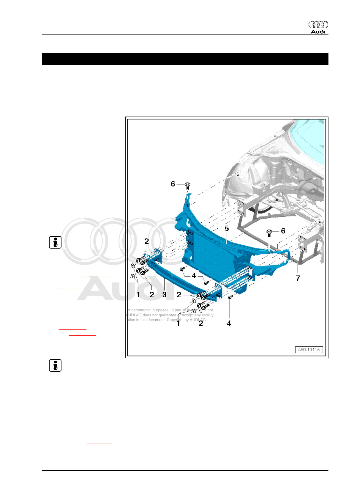
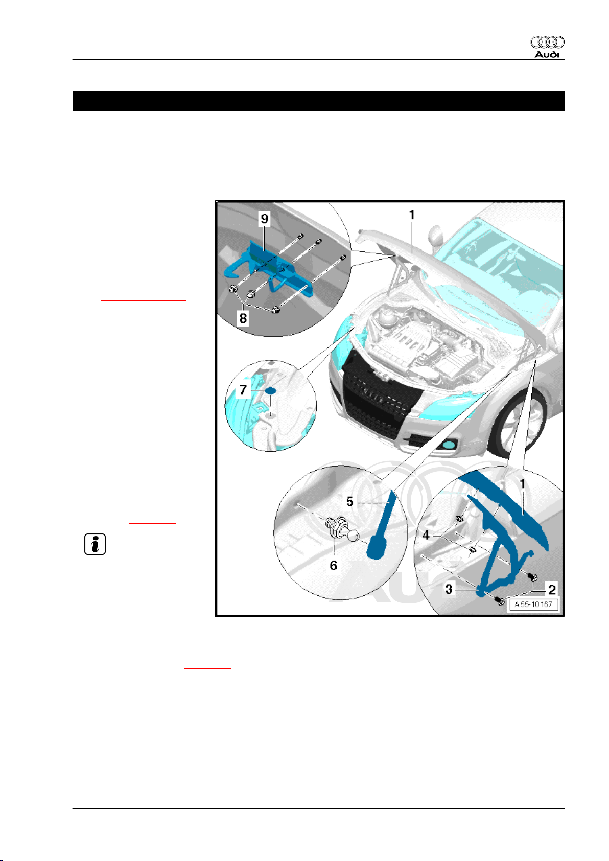
1.1 Removing and installing lock carrier with attachments - exploded view
1 - Lock washer
❑ Used to secure impact
bar in position, does not
have to be detached for
removing lock carrier
2 - Bolt
❑ 30 Nm
3 - Impact bar
❑ Does not need to be de‐
tached from bumper
brackets when remov‐
ing the lock carrier.
4 - Bolt
❑ 6 Nm
5 - Lock carrier
Note
❑ Removing:
– Remove bumper (front):
Audi TT ⇒ page 148 ,
Audi TT RS
⇒ page 156 .
– Remove headlight ⇒
Rep. Gr. 94 .
– Detach cable for bonnet
lock at coupling: Audi TT
⇒ page 18 , Audi TT
RS ⇒ page 41 .
– Unscrew bolts -2- at lon‐
gitudinal member.
Note
– Unscrew bolts -6- at wing and unscrew bolts -4-.
– Detach lock carrier to front.
❑ Install in reverse sequence.
6 - Bolt
❑ 23 Nm
7 - Frame
❑ Removing ⇒ page 4
1. Body - front 3
Page 10
Protected by copyright. Copying for private or commercial purposes, in part or in whole, is not
permitted unless authorised by AUDI AG. AUDI AG does not guarantee or accept any liability
with respect to the correctness of information in this document. Copyright by AUDI AG.
Audi TT 2007 ➤
General body repairs, exterior - Edition 09.2009
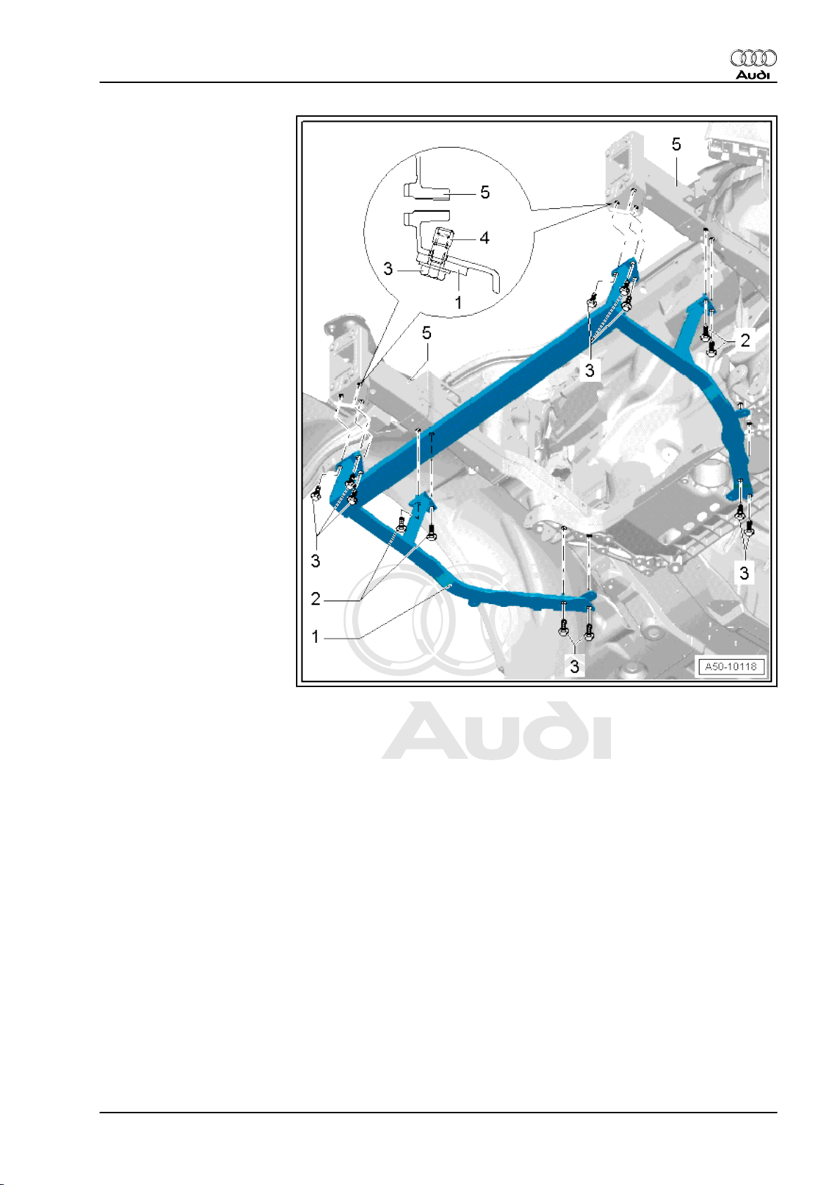
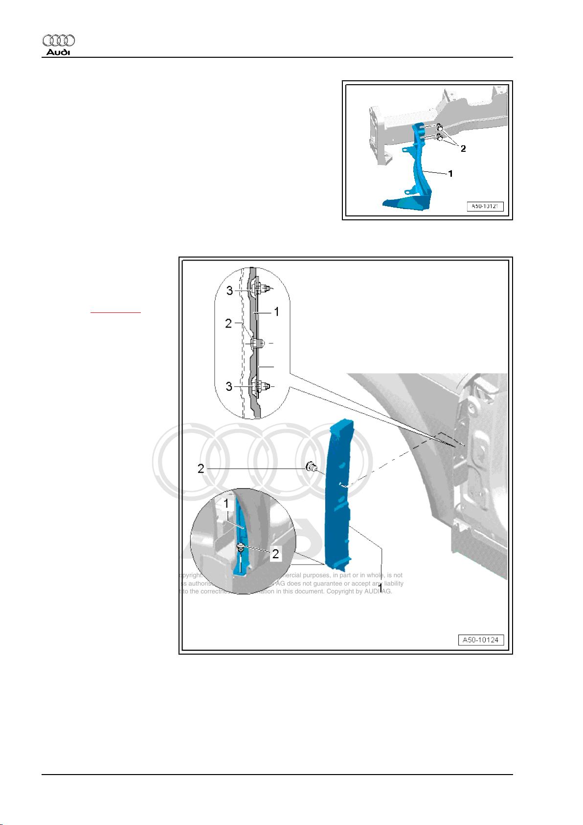
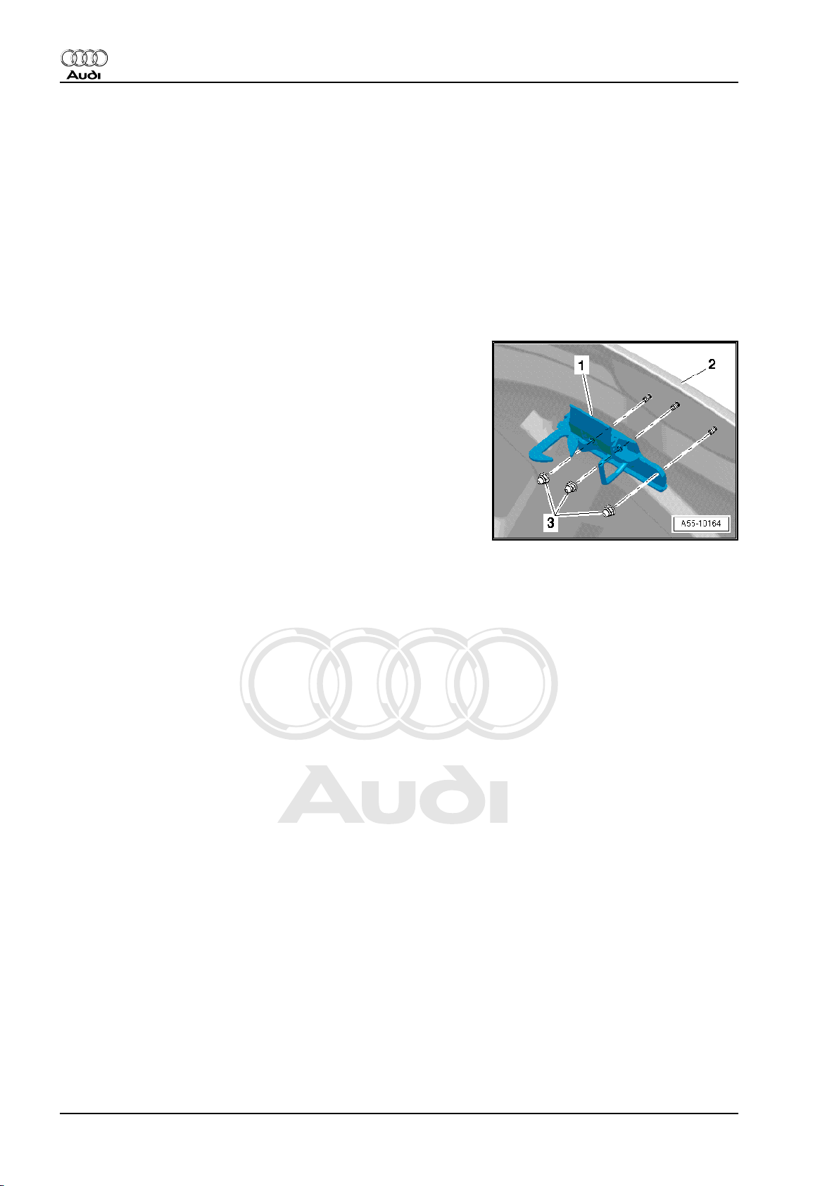
Removing and installing bumper bracket
1 - Bumper bracket (right-side)
2 - Bolt
❑ 5 Nm
3 - Bumper bracket (left-side)
4 - Bumper
Frame for noise insulation
4 Rep. Gr.50 - Body - front
Page 11
Protected by copyright. Copying for private or commercial purposes, in part or in whole, is not
permitted unless authorised by AUDI AG. AUDI AG does not guarantee or accept any liability
with respect to the correctness of information in this document. Copyright by AUDI AG.
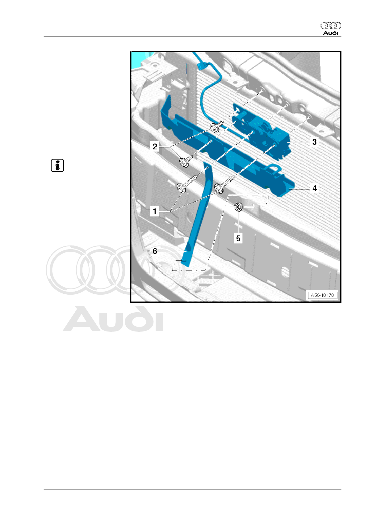
1 - Frame
❑ Noise insulation re‐
moved
❑ Unscrew bolts -2- and
-3- and take out frame.
2 - Bolt
❑ 23 Nm
3 - Bolt
❑ 23 Nm
4 - Pop rivet nut
5 - Longitudinal member
Audi TT 2007 ➤
General body repairs, exterior - Edition 09.2009
1. Body - front 5
Page 12
Protected by copyright. Copying for private or commercial purposes, in part or in whole, is not
permitted unless authorised by AUDI AG. AUDI AG does not guarantee or accept any liability
with respect to the correctness of information in this document. Copyright by AUDI AG.
Audi TT 2007 ➤
General body repairs, exterior - Edition 09.2009
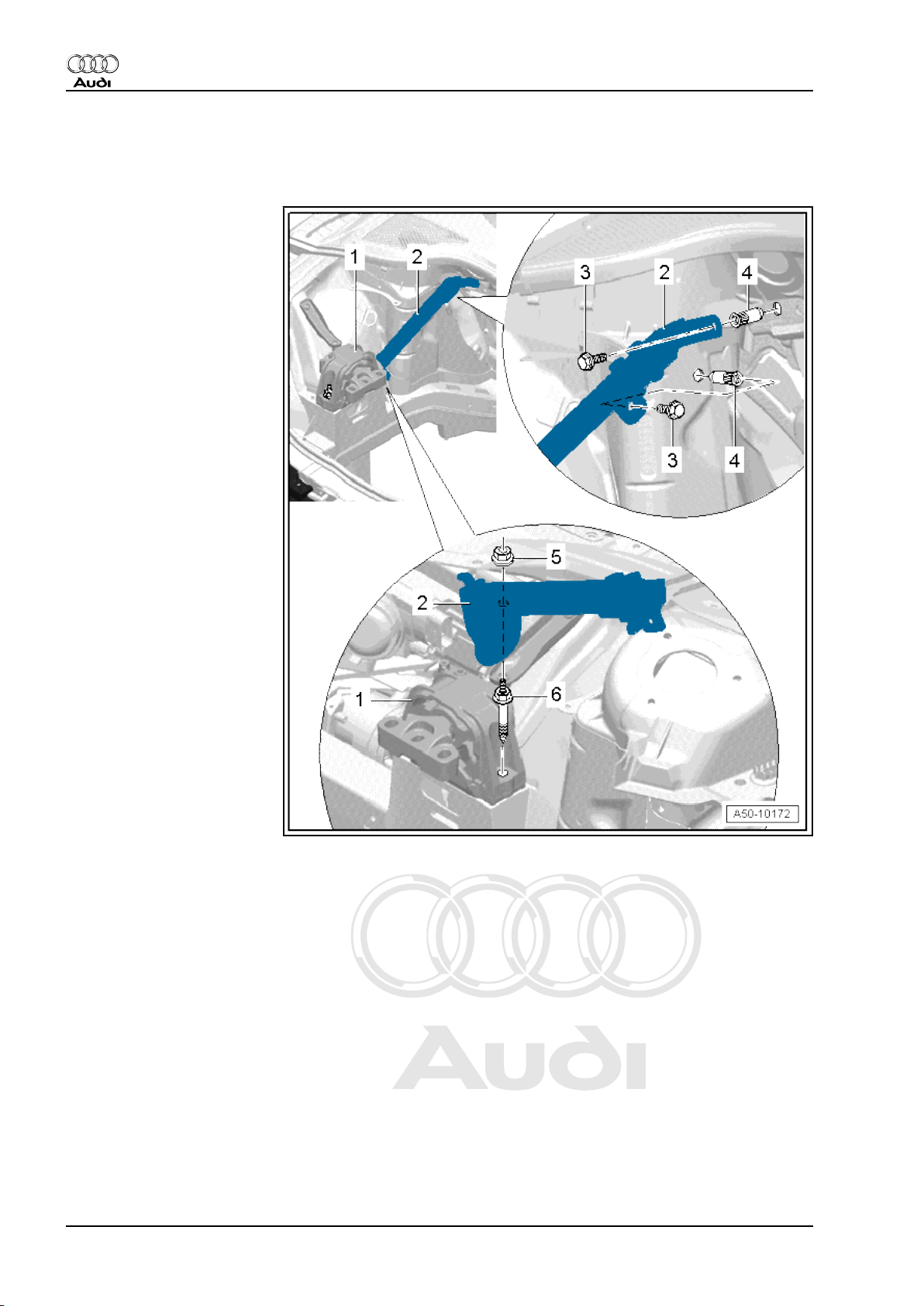
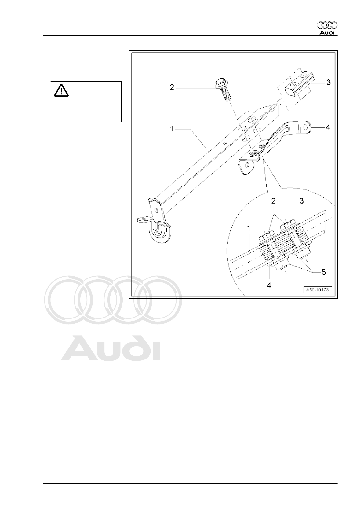
1.2 Strut for engine mounting - exploded view
Only on Roadster; country-specific version
1 - Engine mounting
Removing ⇒ Rep. Gr. 10
2 - Strut for engine mounting
❑ Remove nut -5- and
bolts -3-
3 - Bolt
❑ 23 Nm
4 - Pop rivet nut
5 - Nut
❑ 10 Nm
6 - Special bolt
❑ Do not unscrew bolt
when removing strut
❑ Tightening torque ⇒
Rep. Gr. 10
Reinforcement for strut
6 Rep. Gr.50 - Body - front
Page 13
Protected by copyright. Copying for private or commercial purposes, in part or in whole, is not
permitted unless authorised by AUDI AG. AUDI AG does not guarantee or accept any liability
with respect to the correctness of information in this document. Copyright by AUDI AG.
1 - Strut for engine mounting
❑ Remove bolts -2- if strut
has to be detached from
bracket
WARNING
When installing, rein‐
forcement -3- must be
pushed into strut -1-
2 - Bolt
❑ 23 Nm
❑
When tightening to specified
torque, counterhold at nut -5with open-end spanner
3 - Reinforcement for strut
4 - Bracket
5 - Nut
Audi TT 2007 ➤
General body repairs, exterior - Edition 09.2009
1. Body - front 7
Page 14
Protected by copyright. Copying for private or commercial purposes, in part or in whole, is not
permitted unless authorised by AUDI AG. AUDI AG does not guarantee or accept any liability
with respect to the correctness of information in this document. Copyright by AUDI AG.
Audi TT 2007 ➤
General body repairs, exterior - Edition 09.2009
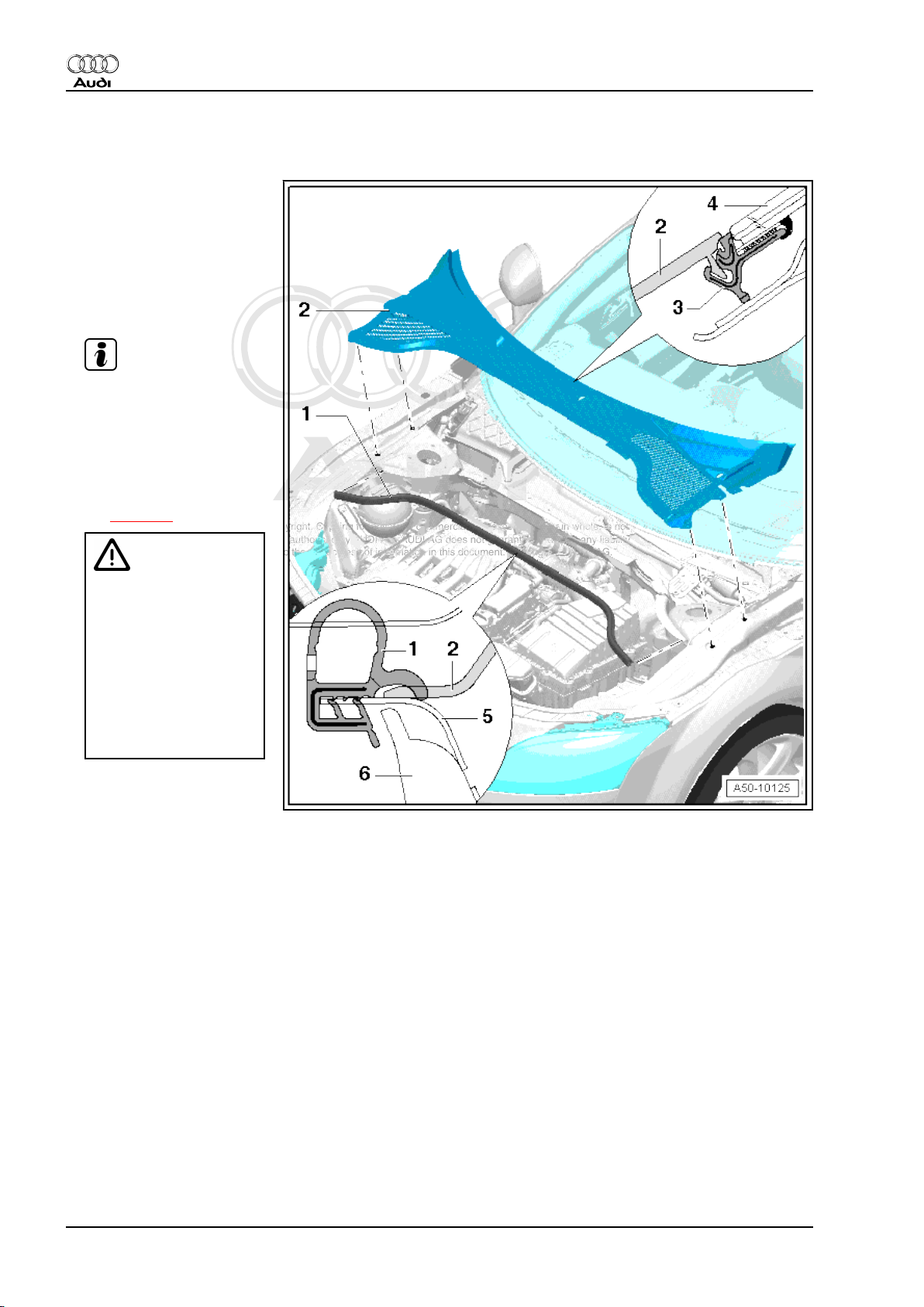
1.3 Removing and installing plenum chamber cover
1 - Seal for bonnet
❑ When fitted correctly,
seal must be positioned
over plenum chamber
cover as shown in detail
view
2 - Plenum chamber cover
❑ Wiper arms removed
Note
❑ Bonnet seal detached
❑ Pull trim panel out of re‐
taining strip, starting at
side of windscreen and
lifting it upwards verti‐
cally.
❑ Vehicles with bolts
⇒ page 9
Caution
Danger of smashing
glass during installation
When installing, trim
panel must not be
knocked on with a ham‐
mer, etc.
Starting at the side, care‐
fully press trim into re‐
taining strip.
3 - Windscreen surround
❑ To facilitate removal / in‐
stallation, spray soap
solution onto the windscreen surround.
❑ Not available as a separate replacement part
4 - Windscreen
5 - Plenum chamber
6 - Bulkhead trim
8 Rep. Gr.50 - Body - front
Page 15
Protected by copyright. Copying for private or commercial purposes, in part or in whole, is not
permitted unless authorised by AUDI AG. AUDI AG does not guarantee or accept any liability
with respect to the correctness of information in this document. Copyright by AUDI AG.
General body repairs, exterior - Edition 09.2009
Plenum chamber cover with bolts
– Remove bolts -3- and -4-.
– Pull off rubber seal -1-.
– Starting at edge of windscreen, carefully pull plenum chamber
cover -2- vertically upwards out of retainer at windscreen
-arrows-.
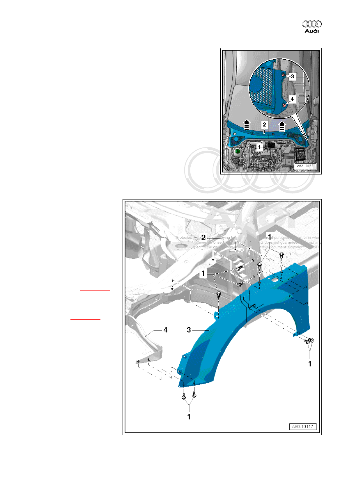
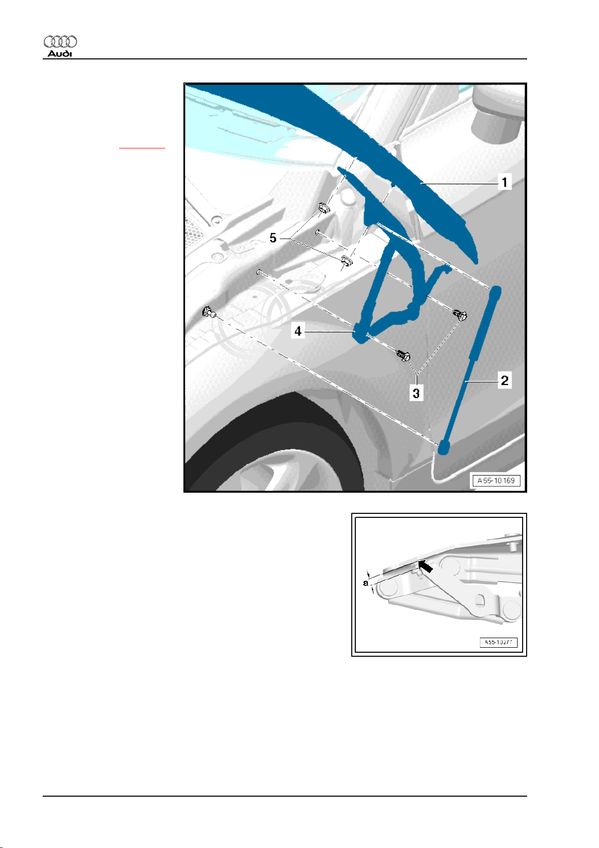
1.4 Removing and installing front wing - exploded view
Audi TT 2007 ➤
1 - Bolt
❑ 11 Nm
2 - Bracket
3 - Wing panel
❑ Removing:
❑ Detach side member
trim in area of wing pan‐
el.
❑ Headlight removed ⇒
Rep. Gr. 94
– Remove bumper (front):
Audi TT ⇒ page 148 ,
Audi TT RS
⇒ page 156 .
– Remove wheel housing
liner ⇒ page 239 .
– Remove end plate
⇒ page 10 .
– Remove bolts and de‐
tach wing.
❑ Install in reverse se‐
quence.
4 - Brace
1. Body - front 9
Page 16
Protected by copyright. Copying for private or commercial purposes, in part or in whole, is not
permitted unless authorised by AUDI AG. AUDI AG does not guarantee or accept any liability
with respect to the correctness of information in this document. Copyright by AUDI AG.
Audi TT 2007 ➤
General body repairs, exterior - Edition 09.2009
Brace for wing panel
– Wing removed
– To remove, only loosen bolts -2- and slide brace forwards out
of elongated holes.
♦ Bolts -2- 23 Nm
Removing and installing end plate
1 - End plate
– Remove front wheel.
– Remove wheel housing
liner ⇒ page 239 .
❑ Detach reservoir.
– Pull out plug -3- and
slide out end plate -1downwards.
❑
2 - Plug
3 - Bolts
❑ 11 Nm
10 Rep. Gr.50 - Body - front
Page 17
Protected by copyright. Copying for private or commercial purposes, in part or in whole, is not
permitted unless authorised by AUDI AG. AUDI AG does not guarantee or accept any liability
with respect to the correctness of information in this document. Copyright by AUDI AG.
General body repairs, exterior - Edition 09.2009
55 – Bonnet, rear lid
1 Bonnet - TT
1.1 Removing and installing bonnet - exploded view
1 - Bonnet
• When removing or instal‐
ling the bonnet, a 2nd me‐
chanic is required to sup‐
port and hold the bonnet.
❑ Removing:
– Detach gas strut
⇒ Item 5 (page 11)
from bonnet
⇒ page 16 .
– Unscrew nuts -4- at bon‐
net hinge at top.
Audi TT 2007 ➤
– Detach bonnet.
❑ Install in reverse se‐
quence.
❑ Adjusting:
– Align bonnet between
wings.
– Adjust height of bonnet
via bottom section of
bonnet lock.
– Adjust position of bon‐
net to wings via bump
stops ⇒ page 15 .
Note
2 - Bolts
❑ 32 Nm
3 - Bonnet hinge
• For removal and installa‐
tion, remove bonnet or support it securely.
❑ Removing:
– Remove gas strut ⇒ page 16 .
– Remove bolts -2- and nuts -4-.
❑ Install in reverse sequence.
4 - Nuts
❑ 25 Nm
5 - Gas strut
❑ Removing and installing ⇒ page 16 .
❑ The cylinder end of the gas strut must be installed on the bonnet side.
1. Bonnet - TT 11
Page 18
Protected by copyright. Copying for private or commercial purposes, in part or in whole, is not
permitted unless authorised by AUDI AG. AUDI AG does not guarantee or accept any liability
with respect to the correctness of information in this document. Copyright by AUDI AG.
Audi TT 2007 ➤
General body repairs, exterior - Edition 09.2009
6 - Ball stud
❑ 21 Nm
7 - Protective film
❑ Self-adhesive
❑ Peel off protective film before mounting.
8 - Nuts
❑ 9 Nm
9 - Arrester
Removing and installing arrester
– Unscrew nuts and detach arrester.
Removing and installing bonnet lock
12 Rep. Gr.55 - Bonnet, rear lid
Page 19
Protected by copyright. Copying for private or commercial purposes, in part or in whole, is not
permitted unless authorised by AUDI AG. AUDI AG does not guarantee or accept any liability
with respect to the correctness of information in this document. Copyright by AUDI AG.
1 - Bolt
❑ 11 Nm
2 - Bolt
❑ 11 Nm
3 - Bonnet lock
❑ Unfasten bumper cover
(top) and press to side.
❑ Detach cable for bonnet
lock at coupling.
❑ Unplug electrical con‐
nector.
❑ Remove bolts -1- and
-2-.
Note
4 - Cover for bonnet lock
5 - Nut
❑ 11 Nm
6 - Brace
Audi TT 2007 ➤
General body repairs, exterior - Edition 09.2009
Removing and installing bonnet hinge
1. Bonnet - TT 13
Page 20
Protected by copyright. Copying for private or commercial purposes, in part or in whole, is not
permitted unless authorised by AUDI AG. AUDI AG does not guarantee or accept any liability
with respect to the correctness of information in this document. Copyright by AUDI AG.
Audi TT 2007 ➤
General body repairs, exterior - Edition 09.2009
1 - Bonnet
2 - Gas strut
❑ Engage cylinder end of
gas strut on bonnet end
❑ Removing ⇒ page 16
3 - Nut
❑ 25 Nm
4 - Hinge for bonnet
– Before removing hinge,
support bonnet or se‐
cure it in position.
❑ Gas strut removed
❑ Remove bolts -3- and
nuts -5-.
❑ Detach bonnet when re‐
moving the two hinges.
5 - Nut
❑ 25 Nm
Adjusting bonnet hinge
♦ When renewing hinge, check dimension -a- = 12.5 mm; adjust
if necessary.
1.2 Adjusting bonnet
Special tools and workshop equipment required
14 Rep. Gr.55 - Bonnet, rear lid
Page 21
Protected by copyright. Copying for private or commercial purposes, in part or in whole, is not
permitted unless authorised by AUDI AG. AUDI AG does not guarantee or accept any liability
with respect to the correctness of information in this document. Copyright by AUDI AG.
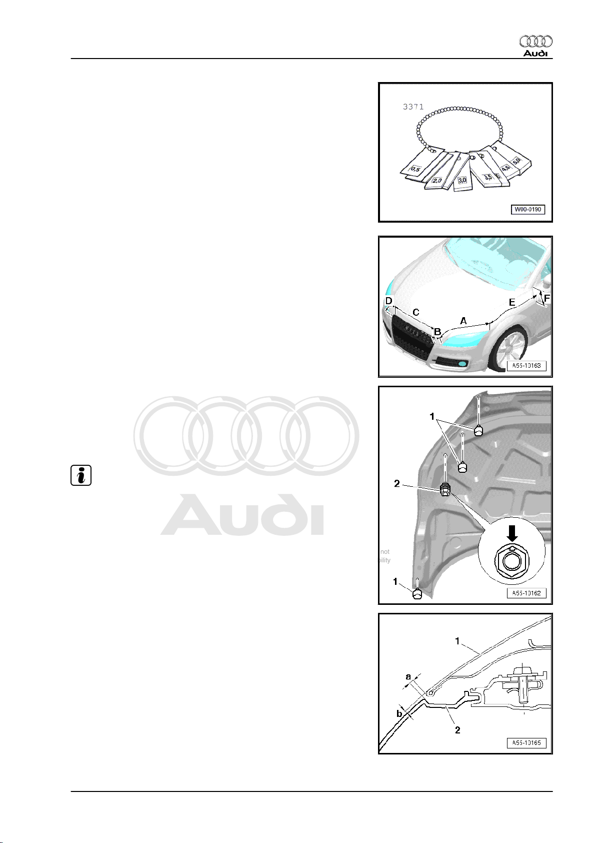
♦ Setting gauge -3371-
Gap widths at bonnet
• In area -A- = 3.5 mm ±0.5 mm
• In area -B- = 4.5 mm ± 0.5 mm
• In area -C- = 4.5 mm ± 0.5 mm
• In area -D- = 4.0 mm ... 2.5 mm (at corner radius)
• In area -E- = 3.5 mm ± 0.5 mm
• In area -F- = 3.5 mm ±0.5 mm
Audi TT 2007 ➤
General body repairs, exterior - Edition 09.2009
Adjusting height of bump stops
• With bonnet closed, adjusting buffers -1- must rest gently on
lock carrier.
• Rubber buffers -2- are used as impact protection and should
not make contact when bonnet is closed.
Note
The adjusting buffers are used to adjust the height of the bonnet.
Projection at bonnet
– When correctly set, the bonnet -1- must project in the area of
the headlights -2-.
• Dimension -a- = 3.5 mm ±0.5 mm
• Projection dimension -b- = 3 mm ±0.5 mm
1. Bonnet - TT 15
Page 22
Protected by copyright. Copying for private or commercial purposes, in part or in whole, is not
permitted unless authorised by AUDI AG. AUDI AG does not guarantee or accept any liability
with respect to the correctness of information in this document. Copyright by AUDI AG.
Audi TT 2007 ➤
General body repairs, exterior - Edition 09.2009
1.3 Removing and installing gas strut - exploded view
1 - Gas strut
❑ To remove, lift locking
spring -arrow- slightly
and detach gas strut
from ball stud.
Note
2 - Bonnet
3 - Ball stud
❑ 21 Nm
Removing
– Support bonnet or secure it in position.
– Use small screwdriver to raise locking spring slightly and de‐
tach gas strut -1- from upper ball stud -2-.
– Repeat procedure at lower ball stud.
Installing
Note
If the gas strut has been completely removed make sure it is reinstalled in the correct position. The cylinder end of the gas strut
must be engaged on the bonnet side.
– Press gas strut onto ball stud and engage.
16 Rep. Gr.55 - Bonnet, rear lid
Page 23
Protected by copyright. Copying for private or commercial purposes, in part or in whole, is not
permitted unless authorised by AUDI AG. AUDI AG does not guarantee or accept any liability
with respect to the correctness of information in this document. Copyright by AUDI AG.
General body repairs, exterior - Edition 09.2009
Releasing gas from gas strut
– Clamp section -x = 50 mm- of gas strut in a vice.
WARNING
♦ Only the section indicated may be clamped in the vice
(accident risk!).
♦ Always wear safety goggles while sawing.
Note
Cover area around saw cut with a cloth to catch any fluid which
may escape.
– Saw open first third of cylinder part of gas strut (measured from
piston rod end of cylinder).
1.4 Removing and installing seal for bonnet
Audi TT 2007 ➤
1 - Lock carrier seal
❑ Slide centrally from rear
onto lock carrier.
2 - Profiled seal (right-side)
❑ Self-adhesive
❑ Pull off protective film
and press onto wing
mounting flange.
3 - Seal for plenum chamber
❑ Starting at the side, slide
into profiled seal (with
pre-tension).
❑ Gradually press on seal
as far as opposite side.
❑ When fitting, tension
seal at corners.
Caution
Squashing in corners is
not permitted
❑ Insert seal in profiled
seal on opposite side in
the same manner.
4 - Plenum chamber cover
❑ Must be inserted be‐
neath lip of plenum
chamber seal.
5 - Profiled seal (left-side)
❑ Self-adhesive
❑ Pull off protective film
and press onto wing
mounting flange.
1. Bonnet - TT 17
Page 24
Protected by copyright. Copying for private or commercial purposes, in part or in whole, is not
permitted unless authorised by AUDI AG. AUDI AG does not guarantee or accept any liability
with respect to the correctness of information in this document. Copyright by AUDI AG.
Audi TT 2007 ➤
General body repairs, exterior - Edition 09.2009
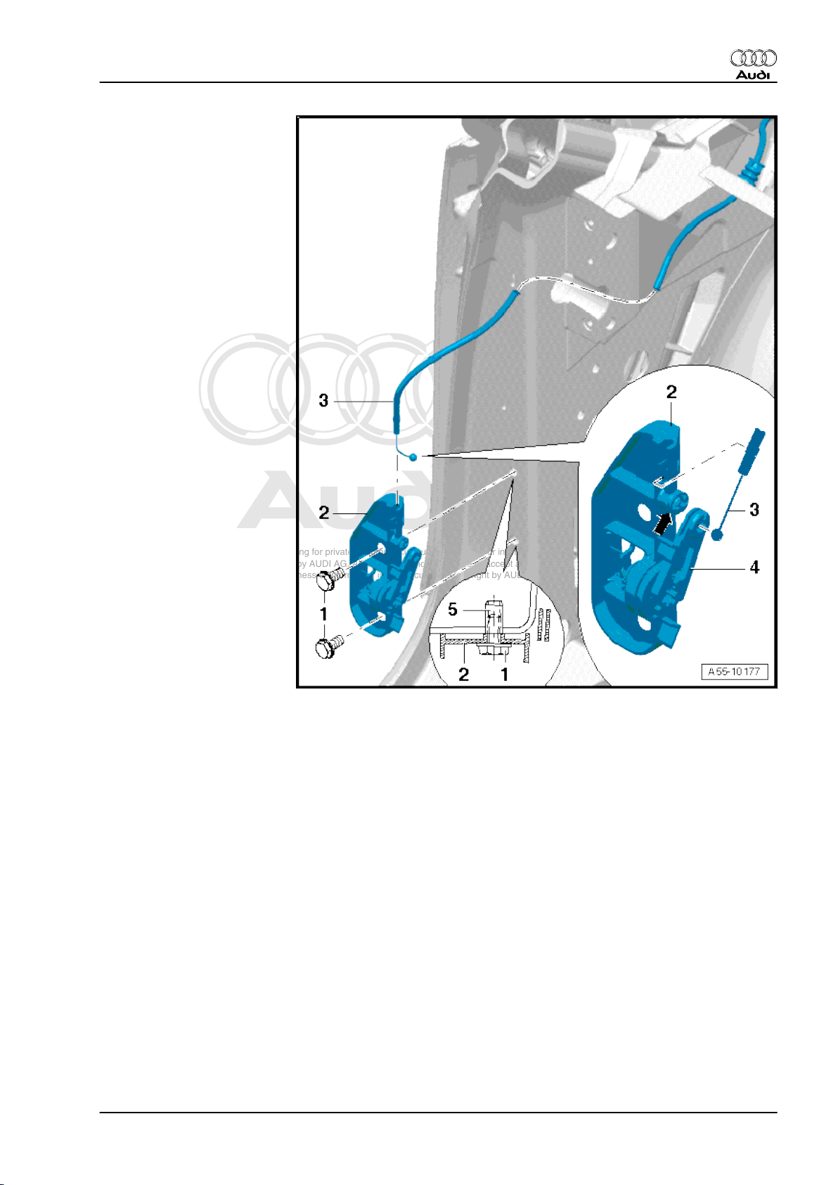
1.5 Removing and installing bonnet lock cable - exploded view
1 - Bonnet lock
❑ Removing and installing
❑ Slide upwards or down‐
wards to adjust bonnet.
2 - Cable for bonnet lock
❑ Removing:
❑ Disconnect cable at
coupling unit
⇒ page 19 .
– Disengage cable from
bracket -7-.
– Pull cable through to‐
wards engine compart‐
ment.
❑ Install in reverse se‐
quence.
3 - Foam sheath
❑ Attached to coupling
unit
4 - Coupling unit for cable
❑ Detach cable at this lo‐
cation before taking out
lock carrier and when
removing release lever.
5 - Grommet
❑ When installing, make
sure it is seated correct‐
ly.
6 - Cover for cable
❑ Attached to edge of pan‐
el
7 - Bracket for cable
❑ Disengaging cable ⇒ page 22
8 - Release lever for bonnet lock
❑ Removing cover for release lever ⇒ page 21
9 - Retaining clip
❑ Attached on side to body flange
10 - Clip
❑ Attached from front to lock carrier
Removing cover for cable
18 Rep. Gr.55 - Bonnet, rear lid
Page 25
Protected by copyright. Copying for private or commercial purposes, in part or in whole, is not
permitted unless authorised by AUDI AG. AUDI AG does not guarantee or accept any liability
with respect to the correctness of information in this document. Copyright by AUDI AG.
1 - Cable
2 - Cover for cable
❑ To remove from body
flange, pull towards
front and then detach
upwards from wing
mounting flange
❑ Unclip cable from cover.
3 - Body flange
4 - Wing mounting flange
Audi TT 2007 ➤
General body repairs, exterior - Edition 09.2009
Coupling unit for cable
1. Bonnet - TT 19
Page 26
Protected by copyright. Copying for private or commercial purposes, in part or in whole, is not
permitted unless authorised by AUDI AG. AUDI AG does not guarantee or accept any liability
with respect to the correctness of information in this document. Copyright by AUDI AG.
Audi TT 2007 ➤
General body repairs, exterior - Edition 09.2009
1 - Cable (rear)
2 - Coupling unit for cable
❑ To release, detach foam
sheath and open cou‐
pling unit.
❑ Lift front cable with nip‐
ple out of coupling unit.
3 - Foam sheath
❑ After fitting cable, slide
sideways over coupling
unit
4 - Cable (front)
Engaging cable in bonnet lock
20 Rep. Gr.55 - Bonnet, rear lid
Page 27
Protected by copyright. Copying for private or commercial purposes, in part or in whole, is not
permitted unless authorised by AUDI AG. AUDI AG does not guarantee or accept any liability
with respect to the correctness of information in this document. Copyright by AUDI AG.
1 - Bonnet lock
2 - Nipple for cable
❑ Insert cable nipple in op‐
erating lever -5-.
❑ Insert cable in bottom
section of bonnet lock
(in direction of arrow)
and slide in until it en‐
gages.
3 - Cable (front)
4 - Guide
❑ Engage cable guide in
bottom section of bon‐
net lock.
5 - Operating lever
❑ Insert cable nipple at
this location
Audi TT 2007 ➤
General body repairs, exterior - Edition 09.2009
Removing cover for operating lever
1. Bonnet - TT 21
Page 28
Protected by copyright. Copying for private or commercial purposes, in part or in whole, is not
permitted unless authorised by AUDI AG. AUDI AG does not guarantee or accept any liability
with respect to the correctness of information in this document. Copyright by AUDI AG.
Audi TT 2007 ➤
General body repairs, exterior - Edition 09.2009
1 - A-pillar trim (bottom)
2 - Cover for operating lever
❑ Before removing, disen‐
gage cable in coupling
in engine compartment
⇒ page 19 .
❑ Raise operating lever by
approx. 90° and pull out
of operating lever to‐
wards centre of vehicle.
3 - Operating lever
Removing operating lever
22 Rep. Gr.55 - Bonnet, rear lid
Page 29
Protected by copyright. Copying for private or commercial purposes, in part or in whole, is not
permitted unless authorised by AUDI AG. AUDI AG does not guarantee or accept any liability
with respect to the correctness of information in this document. Copyright by AUDI AG.
1 - Bolts
❑ 12 Nm
2 - Mounting bracket for oper‐
ating lever
❑ Not available as a sepa‐
rate replacement part
3 - Cable
❑ If fitted correctly, cable
must run in idler roller
-arrow- in mounting
bracket -2-.
4 - Operating lever
❑ Cover for operating lev‐
er removed
❑ A-pillar trim (bottom) re‐
moved
❑ Unscrew bolts -1- and
disengage cable -3-.
5 - Pop rivet nut
Audi TT 2007 ➤
General body repairs, exterior - Edition 09.2009
1. Bonnet - TT 23
Page 30
Protected by copyright. Copying for private or commercial purposes, in part or in whole, is not
permitted unless authorised by AUDI AG. AUDI AG does not guarantee or accept any liability
with respect to the correctness of information in this document. Copyright by AUDI AG.
Audi TT 2007 ➤
General body repairs, exterior - Edition 09.2009
2 Bonnet - TT RS
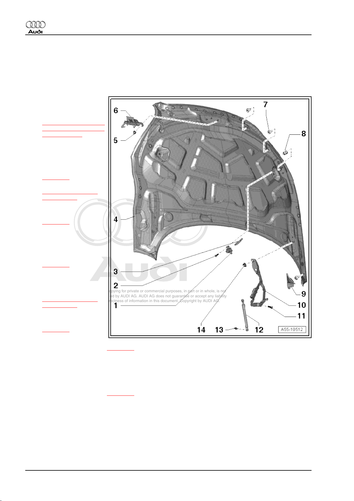
2.1 Bonnet - exploded view
1 - Locating element
❑ For striker
❑ Removing and installing
⇒ “2.5 Removing and in‐
stalling strikers (left and
right)”, page 26
2 - Bolt
❑ 2 Nm
3 - Striker
❑ Removing and installing
⇒ page 26
❑ Adjusting
⇒ “2.8 Adjusting bon‐
net”, page 29
4 - Bonnet
❑ Removing and installing
⇒ page 25
5 - Nuts
❑ 9 Nm
6 - Striker with arrester
❑ Removing and installing
⇒ page 26
7 - Bump stop
8 - Adjusting buffer
❑ Adjusting
⇒ “2.8 Adjusting bon‐
net”, page 29
9 - Impact guard
❑ Removing and installing
⇒ page 26
10 - Bonnet hinge
❑ Removing and installing ⇒ page 25
11 - Bolt
❑ Note different lengths
❑ 34 Nm
12 - Gas strut
❑ Removing and installing ⇒ page 31
13 - Ball stud
❑ 23 Nm
14 - Nut
❑ 34 Nm
24 Rep. Gr.55 - Bonnet, rear lid
Page 31

Protected by copyright. Copying for private or commercial purposes, in part or in whole, is not
permitted unless authorised by AUDI AG. AUDI AG does not guarantee or accept any liability
with respect to the correctness of information in this document. Copyright by AUDI AG.
General body repairs, exterior - Edition 09.2009
2.2 Removing and installing bonnet
Removing
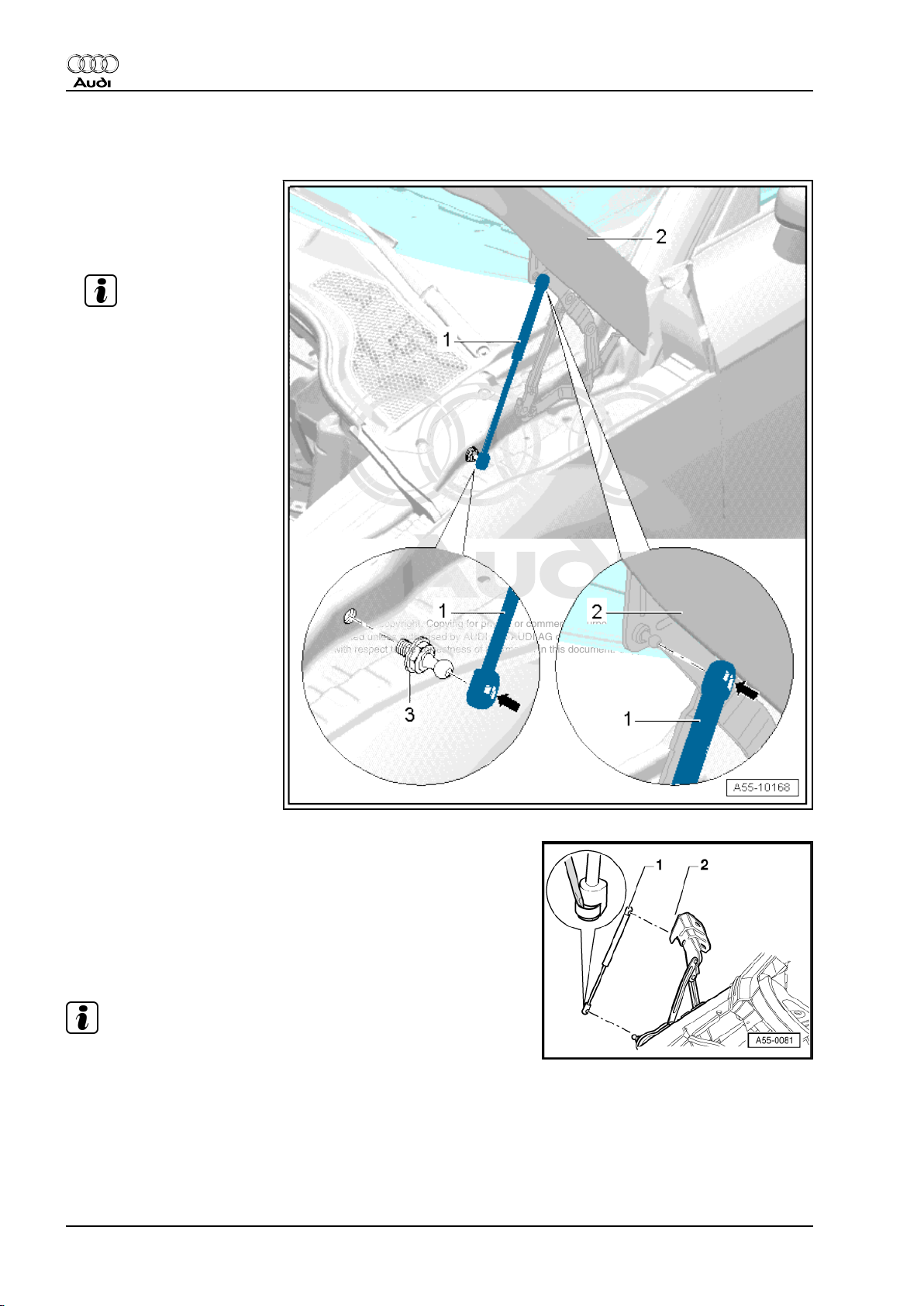
– Remove washer jets ⇒ Rep. Gr. 92 .
– Pull sealing plug -2- out of bonnet.
– Guide electrical wiring harness -3- and washer fluid line -1- out
of bonnet.
WARNING
Risk of injury!
♦ A second mechanic is required to support and hold the
bonnet during removal and installation.
– Unscrew nuts -arrows- (left and right) at hinge.
– Detach bonnet -4-.
Installing
• Tightening torques ⇒ page 24
Installation is carried out in the reverse order; note the following:
– Adjust bonnet ⇒ page 29 .
Audi TT 2007 ➤
2.3 Removing and installing bonnet hinge
Removing
– Remove bonnet ⇒ page 25 .
– Disengage gas strut -2- at bonnet hinge ⇒ page 31 .
– Release retaining tabs and disengage duct -1- at bonnet
hinge.
– Use a felt-tip pen to mark installation position of bonnet hinge
-3- for re-installation.
– Remove bolts -4- and -5-.
Note
Bolts -4- and -5- have different lengths.
– Detach bonnet hinge.
Installing
• Tightening torques ⇒ page 24
Installation is carried out in the reverse order; note the following:
– Set stop bolt -1- for bonnet hinge to dimension -a-.
• Dimension -a- = 34 mm
– Install bonnet hinge according to markings made during re‐
moval.
– Adjust bonnet ⇒ page 29 .
2. Bonnet - TT RS 25
Page 32

Protected by copyright. Copying for private or commercial purposes, in part or in whole, is not
permitted unless authorised by AUDI AG. AUDI AG does not guarantee or accept any liability
with respect to the correctness of information in this document. Copyright by AUDI AG.
Audi TT 2007 ➤
General body repairs, exterior - Edition 09.2009
2.4 Removing and installing striker with ar‐
rester
Removing
– Unscrew cap nuts -3-.
– Detach striker -1- with arrester at bonnet -2-.
Installing
• Tightening torque ⇒ page 24
Install in reverse order of removal.
2.5 Removing and installing strikers (left and right)
Removing
– Open bonnet.
– Remove bolt -1- and detach locating element -2- for striker.
– Remove striker -3- for bonnet lock.
Installing
• Tightening torques ⇒ page 24
Installation is carried out in the reverse order; note the following:
– Adjust striker ⇒ “2.8 Adjusting bonnet”, page 29 .
2.6 Removing and installing impact guard
Special tools and workshop equipment required
♦ Hot-air blower -V.A.G 1416-
♦ Cleaning solution -D 009 401 04-
26 Rep. Gr.55 - Bonnet, rear lid
Page 33

Protected by copyright. Copying for private or commercial purposes, in part or in whole, is not
permitted unless authorised by AUDI AG. AUDI AG does not guarantee or accept any liability
with respect to the correctness of information in this document. Copyright by AUDI AG.
General body repairs, exterior - Edition 09.2009
Removing
– Open bonnet.
– Carefully heat impact guard -1- with hot-air blower -V.A.G
1416- and pull impact guard off bonnet -2- in bonded area.
– Detach impact guard.
Installing
Installation is carried out in the reverse order; note the following:
– Remove any residual adhesive with adhesive strip remover -
VAS 6349- .
– Clean bonding surface on body with cleaning solution -D 009
401 04- .
– Peel off protective film and insert guide -2- on impact guard
-1- into mounting on bonnet -3-.
• Impact guard must be flush with outer edge of bonnet.
– Press on impact guard over entire length.
Audi TT 2007 ➤
2. Bonnet - TT RS 27
Page 34

Protected by copyright. Copying for private or commercial purposes, in part or in whole, is not
permitted unless authorised by AUDI AG. AUDI AG does not guarantee or accept any liability
with respect to the correctness of information in this document. Copyright by AUDI AG.
Audi TT 2007 ➤
General body repairs, exterior - Edition 09.2009
2.7 Gap widths at bonnet
Gap widths of bonnet to radiator grille, bumper and headlights
A - Bonnet to bumper
• Gap width -a- = 4.5 ±
0.5 mm
-1- Bonnet
-2- Bumper
❑ Adjusting ⇒ page 29
B - Bonnet to radiator grille (at
side)
• Gap width -b- (from top to
bottom) = 4.0 … 2.5 ± 0.5
mm
-1- Bonnet
-3- Radiator grille
❑ Adjusting ⇒ page 29
C - Bonnet to radiator grille
• Gap width -c- = 4.4 ±
0.5 mm
• Projection -d- = 1.5 ± 0.5
mm
-1- Bonnet
-3- Radiator grille
❑ Adjusting ⇒ page 29
D - Bonnet to headlight
• Gap width -e- (from top to
bottom) = 3.0 … 1.6 ± 0.5
mm
• Projection -f- = 3.0 ± 0.5
mm
Gap widths of bonnet to wing and front door
28 Rep. Gr.55 - Bonnet, rear lid
Page 35

Protected by copyright. Copying for private or commercial purposes, in part or in whole, is not
permitted unless authorised by AUDI AG. AUDI AG does not guarantee or accept any liability
with respect to the correctness of information in this document. Copyright by AUDI AG.
A - Bonnet to wing (in area of
headlight)
• Gap width -a- = 2.5 ±
0.5 mm
-1- Bonnet
-2- Wing (front section)
❑ Adjusting ⇒ page 29
B - Bonnet to front door
• Gap width -b- = 3.5 ±
0.5 mm
• Projection -c- = 0.0 + 1.0
mm
-1- Bonnet
-3- Front door
❑ Adjusting ⇒ page 29
C - Bonnet to wing (in area of
A-pillar)
• Gap width -d- = 3.5 ±
0.5 mm
• Projection -e- = 2.0 ± 0.5
mm
-1- Bonnet
-4- Wing (rear section)
❑ Adjusting ⇒ page 29
Audi TT 2007 ➤
General body repairs, exterior - Edition 09.2009
2.8 Adjusting bonnet
Special tools and workshop equipment required
♦ Setting gauge -3371-
2. Bonnet - TT RS 29
Page 36

Protected by copyright. Copying for private or commercial purposes, in part or in whole, is not
permitted unless authorised by AUDI AG. AUDI AG does not guarantee or accept any liability
with respect to the correctness of information in this document. Copyright by AUDI AG.
Audi TT 2007 ➤
General body repairs, exterior - Edition 09.2009
Procedure
• Gap widths ⇒ page 28
• Tightening torques ⇒ page 24
Lateral and longitudinal adjustment at hinge:
– Loosen nuts -A- at hinge -2- on both sides.
– Adjust bonnet -1- (lateral and longitudinal adjustment).
– Tighten nuts.
Height adjustment at hinge:
– Loosen bolts -B- and -C- at hinge on both sides.
– Adjust height of hinge -2- in area of bolt -B-.
– Tighten bolts.
Note
Check height adjustment of stop bolt for bonnet hinge
⇒ page 25 .
Height adjustment at bonnet lock:
• Tightening torque ⇒ page 33
– Loosen bolts -arrows-.
– Adjust height of bonnet lock -1- in lock carrier (front) -2-.
• The bonnet striker with arrester must engage vertically in the
bonnet lock.
– Tighten bolts.
Height adjustment at bonnet lock (left and right):
• Tightening torque ⇒ page 24
– Remove bolt -1- and detach locating element -2- for striker.
– Screw striker -3- for bonnet lock as far as it will go into bonnet
and then screw out by 3 turns.
• Closing check for bonnet: Bonnet must fall into bonnet lock
from neutral position and engage fully.
– If necessary, adjust height of striker.
– Fit locating element -2- onto striker -3-.
– Secure locating element with bolt.
30 Rep. Gr.55 - Bonnet, rear lid
Page 37

Protected by copyright. Copying for private or commercial purposes, in part or in whole, is not
permitted unless authorised by AUDI AG. AUDI AG does not guarantee or accept any liability
with respect to the correctness of information in this document. Copyright by AUDI AG.
General body repairs, exterior - Edition 09.2009
Adjusting bump stop:
• Inner bump stops -1- are used as impact protection and should
not make contact when bonnet is closed.
– Turn bump stops for bonnet to adjust height -arrows-.
2.9 Removing and installing gas strut and
releasing gas from gas strut
Note
Different gas struts are installed; the procedures for removal also
differ.
Audi TT 2007 ➤
Removing gas strut with steel spring
WARNING
Risk of accident.
♦ Before removing a gas strut, support bonnet or secure it
in position.
– Disengage gas strut for bonnet; to do so, lift retaining spring
-2- -arrow- with a small screwdriver -1- and detach gas strut
-3- from ball stud.
Removing gas strut with plastic clip
– Using commercially available long-nose pliers, compress
plastic clip -1- as shown and pull gas strut -2- off ball stud.
Installing
Installation is carried out in the reverse order; note the following:
• The cylinder end of the gas strut must be installed on the bon‐
net side.
– Press gas strut onto ball stud until it engages audibly.
2. Bonnet - TT RS 31
Page 38

Protected by copyright. Copying for private or commercial purposes, in part or in whole, is not
permitted unless authorised by AUDI AG. AUDI AG does not guarantee or accept any liability
with respect to the correctness of information in this document. Copyright by AUDI AG.
Audi TT 2007 ➤
General body repairs, exterior - Edition 09.2009
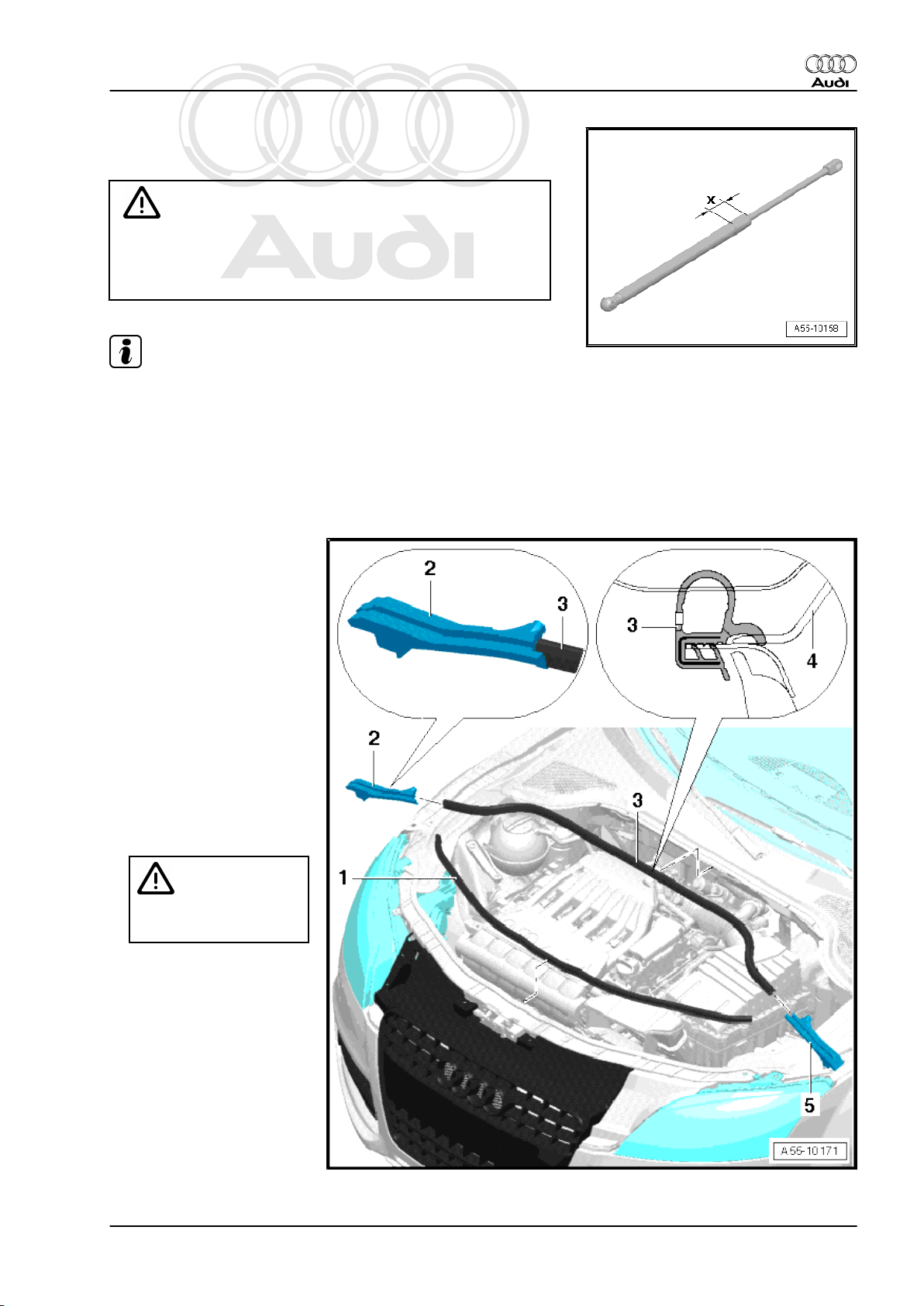
Releasing gas from gas strut
– Clamp section -x = 50 mm- of gas strut in a vice.
WARNING
Risk of injury!
♦ It is important to only clamp this section.
♦ Always wear safety goggles while sawing.
Note
Cover area around saw notch with a cloth to catch any escaping
fluid.
– Saw open first third of cylinder part of gas strut (measured from
piston rod end of cylinder).
32 Rep. Gr.55 - Bonnet, rear lid
Page 39

Protected by copyright. Copying for private or commercial purposes, in part or in whole, is not
permitted unless authorised by AUDI AG. AUDI AG does not guarantee or accept any liability
with respect to the correctness of information in this document. Copyright by AUDI AG.
3 Bonnet lock - TT RS
3.1 Bonnet lock - exploded view
1 - Nut
❑ 9 Nm
2 - Brace
3 - Bolt
❑ 11 Nm
4 - Bolt
❑ 11 Nm
5 - Anti-theft bracket
6 - Bonnet lock (right-side)
❑ Removing and installing
⇒ page 35
7 - Mounting (right-side) for
bonnet lock
8 - Bolt
❑ 3 Nm
9 - Mounting (left-side) for bon‐
net lock
10 - Bolt
❑ 10 Nm
11 - Bonnet lock (left-side)
❑ Removing and installing
⇒ page 35
12 - Bonnet lock
❑ With bonnet contact
switch -F266-
❑ Can be used to adjust
height of bonnet
⇒ page 29
❑ Removing and installing
⇒ page 34
13 - Bolt
❑ 11 Nm
Audi TT 2007 ➤
General body repairs, exterior - Edition 09.2009
3. Bonnet lock - TT RS 33
Page 40

Protected by copyright. Copying for private or commercial purposes, in part or in whole, is not
permitted unless authorised by AUDI AG. AUDI AG does not guarantee or accept any liability
with respect to the correctness of information in this document. Copyright by AUDI AG.
Audi TT 2007 ➤
General body repairs, exterior - Edition 09.2009
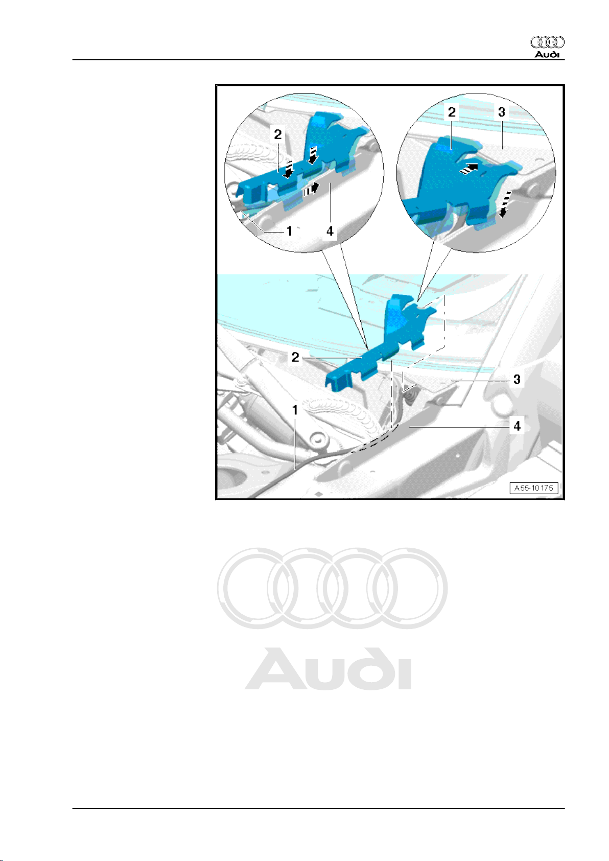
3.2 Removing and installing bonnet lock
Removing
– Detach bonnet contact switch -F266- only at bonnet lock
⇒ page 97 .
– Prise retaining clips -3- off cable guide -2-.
– Remove bolts -arrows-.
– Detach bonnet lock -1- from lock carrier.
– Press release lever at cable -1- in direction of -arrow A-.
– Swivel support bracket with cable in direction of -arrow B- and
disengage it at bonnet lock -2-.
Installing
• Tightening torque ⇒ page 33
Installation is carried out in the reverse order; note the following:
– Engage support bracket -5- with cable at bonnet lock -2-
-arrow- and swivel it forwards towards bonnet lock until catch
-1- engages. This causes cable nipple -4- to engage at oper‐
ating lever -3- for bonnet lock release.
– Install bonnet contact switch -F266- at bonnet lock
⇒ page 97 .
– Adjust bonnet ⇒ page 29 .
34 Rep. Gr.55 - Bonnet, rear lid
Page 41

Protected by copyright. Copying for private or commercial purposes, in part or in whole, is not
permitted unless authorised by AUDI AG. AUDI AG does not guarantee or accept any liability
with respect to the correctness of information in this document. Copyright by AUDI AG.
General body repairs, exterior - Edition 09.2009
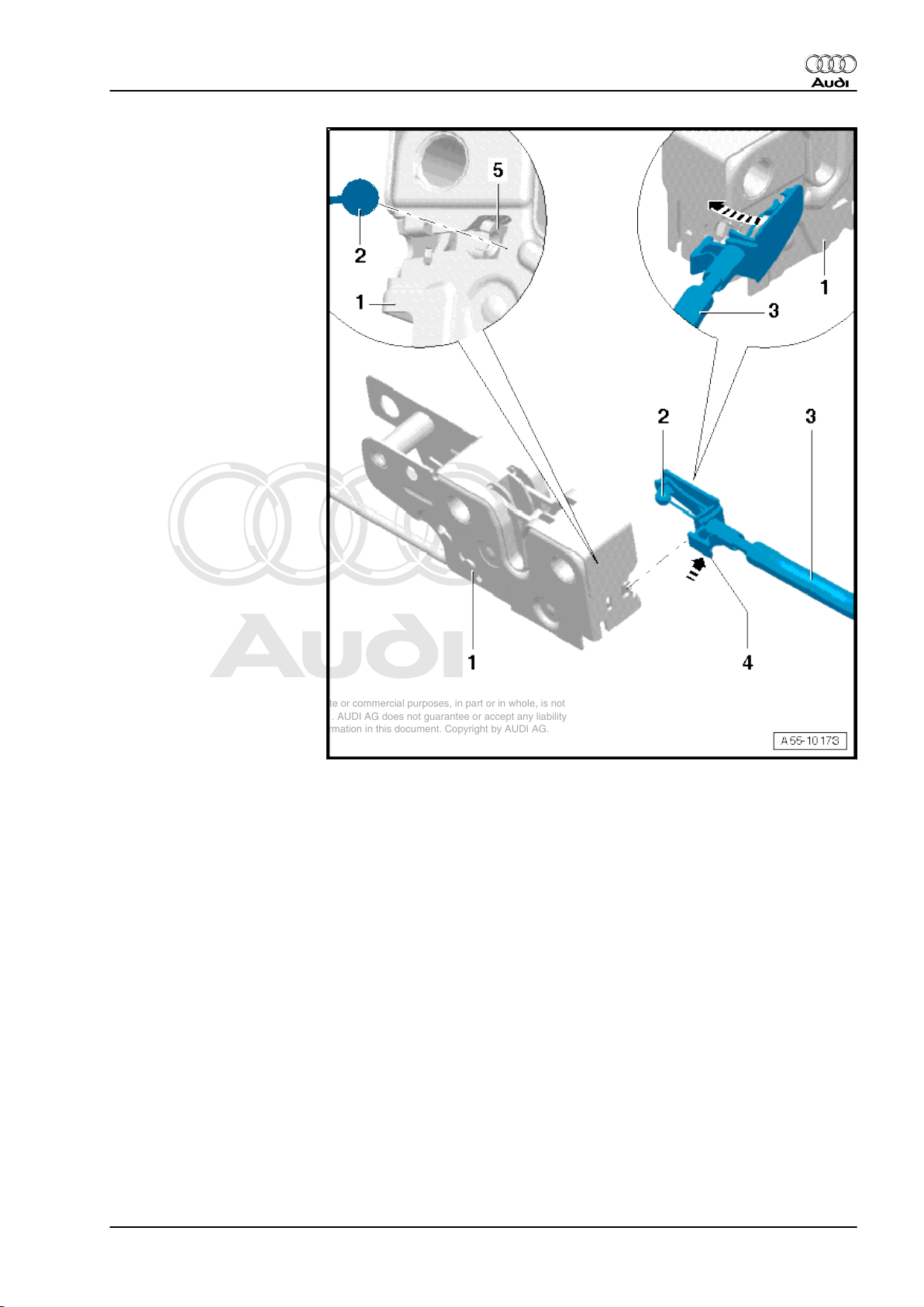
3.3 Removing and installing bonnet lock
(left and right)
Removing
– Remove bolts -arrows-.
– Take out bonnet lock -1- until cable is visible.
– Release retaining tab -1- -arrow A- and pull cable support
bracket out of mounting -2- -arrow B-.
– Pull cable nipple -3- out of release lever -4- at bonnet lock.
– Detach bonnet lock.
Installing
• Tightening torque ⇒ page 33
Installation is carried out in the reverse order; note the following:
– Adjust bonnet ⇒ page 29 .
Audi TT 2007 ➤
3. Bonnet lock - TT RS 35
Page 42

Protected by copyright. Copying for private or commercial purposes, in part or in whole, is not
permitted unless authorised by AUDI AG. AUDI AG does not guarantee or accept any liability
with respect to the correctness of information in this document. Copyright by AUDI AG.
Audi TT 2007 ➤
General body repairs, exterior - Edition 09.2009
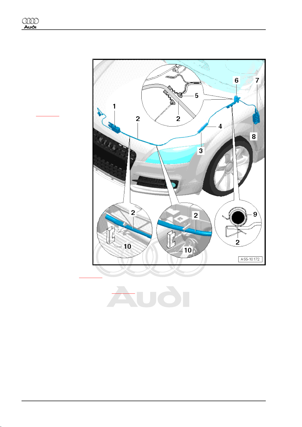
3.4 Cable for bonnet and cable operating lever - exploded view
1 - Bonnet lock
2 - Cable (right-side)
❑ For bonnet lock (right-
side)
❑ Removing and installing
⇒ page 40
3 - Bonnet lock (right-side)
4 - Mounting bracket
❑ For cables leading to
bonnet locks (left and
right)
❑ Removing and installing
⇒ page 41
5 - Cover
❑ For cable
6 - Grommet
❑ To seal off passenger
compartment
7 - Bolt
❑ 10 Nm
8 - Mounting bracket for oper‐
ating lever
❑ Removing and installing
⇒ page 37
9 - Operating lever
10 - Retaining clip
❑ For mounting bracket
with cable
11 - Bonnet lock (left-side)
❑ Removing and installing
⇒ page 35
12 - Cable (left-side)
❑ For bonnet lock (left-side)
❑ Removing and installing ⇒ page 39
❑ Adjusting ⇒ page 43
13 - Cable
❑ For bonnet lock
❑ Removing and installing ⇒ page 37
36 Rep. Gr.55 - Bonnet, rear lid
Page 43

Protected by copyright. Copying for private or commercial purposes, in part or in whole, is not
permitted unless authorised by AUDI AG. AUDI AG does not guarantee or accept any liability
with respect to the correctness of information in this document. Copyright by AUDI AG.
General body repairs, exterior - Edition 09.2009
3.5 Removing and installing mounting
bracket for operating lever
Removing
– Remove dash panel trim (driver side) ⇒ Rep. Gr. 70 .
– Remove A-pillar trim (bottom) ⇒ Rep. Gr. 70 .
– Remove bolts -1- and -2-.
– Pull cable -4- for bonnet out of support bracket and detach at
idler roller -arrow-.
– Disengage cable nipple -5- from operating lever -6-.
– Detach mounting bracket -3- for operating lever.
Installing
Installation is carried out in the reverse order; note the following:
• Tightening torque ⇒ page 36
– Cable nipple must be inserted correctly in operating lever.
– Insert cable in idler roller and press cable sleeve into support
bracket.
– Install A-pillar trim (bottom) ⇒ Rep. Gr. 70 .
– Install dash panel trim (driver side) ⇒ Rep. Gr. 70 .
Audi TT 2007 ➤
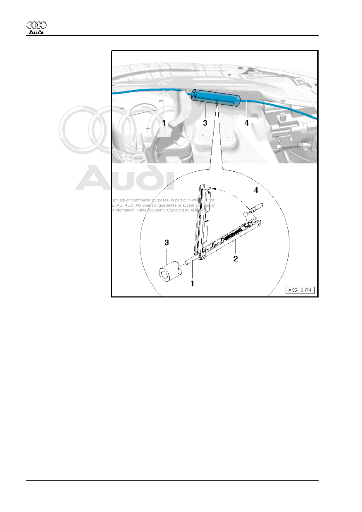
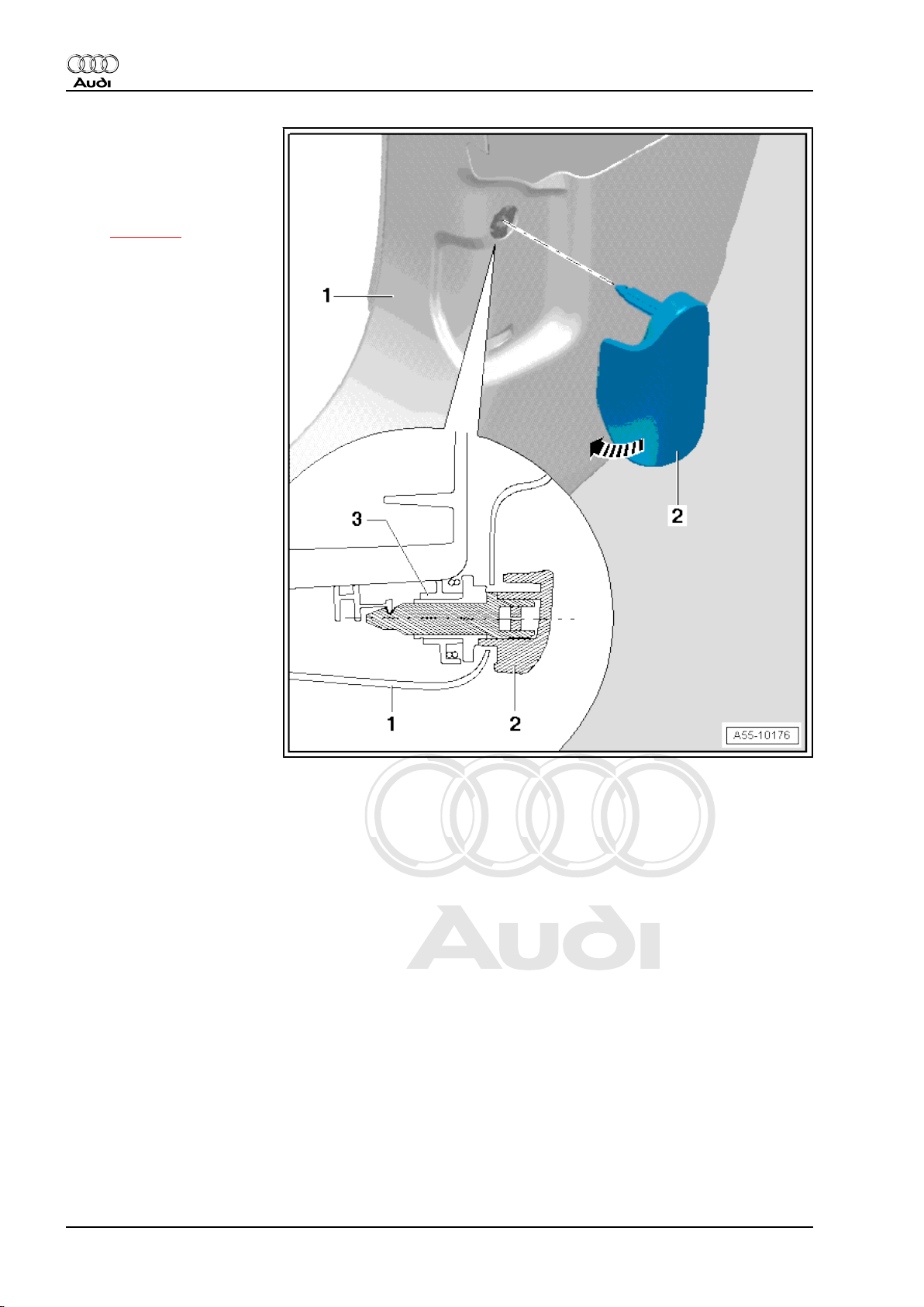
3.6 Removing and installing cable for bon‐
net lock
Removing
– Remove bumper ⇒ page 156 .
– Remove bolts -arrows-.
– Detach air duct -1-.
3. Bonnet lock - TT RS 37
Page 44

Protected by copyright. Copying for private or commercial purposes, in part or in whole, is not
permitted unless authorised by AUDI AG. AUDI AG does not guarantee or accept any liability
with respect to the correctness of information in this document. Copyright by AUDI AG.
Audi TT 2007 ➤
General body repairs, exterior - Edition 09.2009
– Unscrew nut -1- and bolts -3- and -4-.
– Detach brace -6-.
– Disengage anti-theft bracket -2- from bottom of lock carrier
-5- -arrows- and detach.
– Prise retaining clips -3- off cable guide -2-.
– Remove bolts -arrows-.
– Detach bonnet lock -1- from lock carrier.
– Press release lever at cable -1- in direction of -arrow A-.
– Swivel support bracket with cable in direction of -arrow B- and
disengage it at bonnet lock -2-.
38 Rep. Gr.55 - Bonnet, rear lid
Page 45

Protected by copyright. Copying for private or commercial purposes, in part or in whole, is not
permitted unless authorised by AUDI AG. AUDI AG does not guarantee or accept any liability
with respect to the correctness of information in this document. Copyright by AUDI AG.
General body repairs, exterior - Edition 09.2009
– Slide both locking bars in direction of -arrows- and detach
cover for engine compartment electronics box.
– Push foam sleeve -7- at cable mounting bracket -6- to one
side.
– Cut through cable tie -arrow-.
– Release retaining clips and open cover.
– Take cable support bracket -4- out of cable mounting bracket
-1-.
– Disengage cable nipple for bonnet lock from connecting piece
-2-.
Audi TT 2007 ➤
Note
Ignore -items 3 and 5-.
– Guide cable out towards front through opening in lock carrier.
Installing
Installation is carried out in the reverse order; note the following:
Note
Re-attach all cable ties at the same locations when re-installing.
– Install cover for engine compartment electronics box ⇒ Rep.
Gr. 97 .
– Install bonnet lock ⇒ page 34 .
– Install bumper ⇒ page 156 .
3.7 Removing and installing cable for bon‐
net lock (left-side)
Removing
– Remove bonnet lock (left-side) ⇒ page 35 .
– Slide both locking bars in direction of -arrows- and detach
cover for engine compartment electronics box.
3. Bonnet lock - TT RS 39
Page 46

Protected by copyright. Copying for private or commercial purposes, in part or in whole, is not
permitted unless authorised by AUDI AG. AUDI AG does not guarantee or accept any liability
with respect to the correctness of information in this document. Copyright by AUDI AG.
Audi TT 2007 ➤
General body repairs, exterior - Edition 09.2009
– Push foam sleeve -7- at cable mounting bracket -6- to one
side.
– Cut through cable tie -arrow-.
– Release retaining clips and open cover.
– Take cable support bracket -3- out of cable mounting bracket
-1-.
– Disengage cable nipple for bonnet lock (left-side) from con‐
necting piece -2-.
Note
Ignore -items 4 and 5-.
– Cut open cable tie and detach cable for bonnet lock.
Installing
Installation is carried out in the reverse order; note the following:
Note
Re-attach all cable ties at the same locations when re-installing.
– Install bonnet lock (left-side) ⇒ page 35 .
– Install cover for engine compartment electronics box ⇒ Rep.
Gr. 97 .
3.8 Removing and installing cable for bon‐
net lock (right-side)
Removing
– Slide both locking bars in direction of -arrows- and detach
cover for engine compartment electronics box.
40 Rep. Gr.55 - Bonnet, rear lid
Page 47

Protected by copyright. Copying for private or commercial purposes, in part or in whole, is not
permitted unless authorised by AUDI AG. AUDI AG does not guarantee or accept any liability
with respect to the correctness of information in this document. Copyright by AUDI AG.
General body repairs, exterior - Edition 09.2009
– Push foam sleeve -7- at cable mounting bracket -6- to one
side.
– Cut through cable tie -arrow-.
– Release retaining clips and open cover.
– Take cable support bracket -5- out of cable mounting bracket
-1-.
– Disengage cable nipple for bonnet lock (right-side) from con‐
necting piece -2-.
Note
Ignore -items 3 and 4-.
– Unscrew bolts -arrows- and detach air duct.
– Remove bonnet lock (right-side) ⇒ page 35 .
– Cut open cable tie and detach cable for bonnet lock.
Installing
Installation is carried out in the reverse order; note the following:
Audi TT 2007 ➤
Note
Re-attach all cable ties at the same locations when re-installing.
– Install bonnet lock (right-side) ⇒ page 35 .
– Install cover for engine compartment electronics box ⇒ Rep.
Gr. 97 .
3.9 Removing and installing mounting bracket for bonnet lock cables
Removing
– Slide both locking bars in direction of -arrows- and detach
cover for engine compartment electronics box.
3. Bonnet lock - TT RS 41
Page 48

Protected by copyright. Copying for private or commercial purposes, in part or in whole, is not
permitted unless authorised by AUDI AG. AUDI AG does not guarantee or accept any liability
with respect to the correctness of information in this document. Copyright by AUDI AG.
Audi TT 2007 ➤
General body repairs, exterior - Edition 09.2009
– Push foam sleeve -7- at cable mounting bracket -6- to one
side.
– Cut through cable tie -arrow-.
– Release retaining clips and open cover.
– Take cable support brackets -3, 4, 5- out of cable mounting
bracket -1-.
– Disengage cable nipple for bonnet lock from connecting piece
-2-.
– Remove dash panel trim (driver side) ⇒ Rep. Gr. 70 .
– Remove A-pillar trim (bottom) ⇒ Rep. Gr. 70 .
– Pull cable -2- for bonnet out of support bracket -1- and detach
at idler roller -arrow-.
– Disengage cable nipple -3- from operating lever -4-.
– Remove wiper arms ⇒ Rep. Gr. 92 .
– Remove bolts -3- and -4-.
– Pull off rubber seal -1-.
Caution
Risk of damage to plenum chamber cover.
♦ Coat transition between windscreen and plenum chamber
cover with a small amount of soap solution.
– Starting at edge of windscreen, carefully pull plenum chamber
cover -2- vertically upwards out of retainer at windscreen
-arrows-.
42 Rep. Gr.55 - Bonnet, rear lid
Page 49

Protected by copyright. Copying for private or commercial purposes, in part or in whole, is not
permitted unless authorised by AUDI AG. AUDI AG does not guarantee or accept any liability
with respect to the correctness of information in this document. Copyright by AUDI AG.
General body repairs, exterior - Edition 09.2009
– Detach cover -4- and take cable out of retaining clip -3-.
– Pull sealing grommet -1- with cable -2- out of opening in body.
– Remove cable mounting bracket for bonnet lock.
Installing
Installation is carried out in the reverse order; note the following:
– Install plenum chamber cover ⇒ page 8 .
– Install cover for engine compartment electronics box ⇒ Rep.
Gr. 97 .
– Engage cable nipple -3- in operating lever -4-.
– Guide cable -2- for bonnet over idler roller -arrow- and press
it into support bracket -1-.
– Install A-pillar trim (bottom) ⇒ Rep. Gr. 70 .
– Install dash panel trim (driver side) ⇒ Rep. Gr. 70 .
Audi TT 2007 ➤
3.10 Adjusting cables for bonnet lock
Procedure
When the release lever is operated, the bonnet locks (left and
right) should be operated simultaneously.
– Set bonnet locks (left and right) to “closed” position:
• The operating cables should allow the catches on the bonnet
locks to engage fully.
• The operating cables -1- and -2- should then be slack.
– If necessary, turn operating cable adjuster -3- accordingly
-arrows-.
3. Bonnet lock - TT RS 43
Page 50

Protected by copyright. Copying for private or commercial purposes, in part or in whole, is not
permitted unless authorised by AUDI AG. AUDI AG does not guarantee or accept any liability
with respect to the correctness of information in this document. Copyright by AUDI AG.
Audi TT 2007 ➤
General body repairs, exterior - Edition 09.2009
4 Rear lid - Coupé
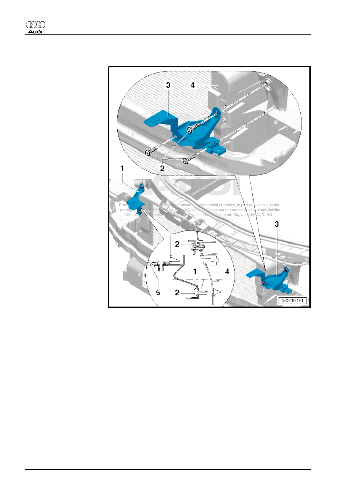
4.1 Removing and installing rear lid - exploded view
1 - Rear lid
• When removing or instal‐
ling the rear lid, a 2nd me‐
chanic is required to sup‐
port and hold the rear lid.
❑ Removing:
– Remove rear lid lining ⇒
Rep. Gr. 70 .
– Disconnect wiring and
pull out of rear lid.
– Remove gas struts (left
and right) ⇒ page 48 .
– Unscrew bolts connect‐
ing rear lid hinges to rear
lid ⇒ page 47 .
– Detach rear lid.
❑ Install in reverse se‐
quence.
❑ Adjusting:
• Gas struts must be fitted
before adjusting new rear
lid.
– Height and longitudinal
adjustments at top of
rear lid must be made
via rear lid hinge.
– Height adjustments at
bottom of rear lid must
be made via rear lid
lock.
– Align rear lid centrally
according to specified gap widths ⇒ page 46 .
– Adjust bump stops ⇒ Item 2 (page 44) .
❑ Removing and installing seal for rear lid ⇒ page 53 .
2 - Bump stop
❑ With the rear lid correctly adjusted and closed, the adjusting buffers must rest lightly against the body.
❑ Adjusting ⇒ page 45 .
3 - Pop rivet
❑ To remove, drill out rivet heads and knock out rivet stems.
4 - Rear lid lock
❑ To remove, unscrew bolts with washers and disengage cable.
5 - Nuts
❑ 21 Nm
44 Rep. Gr.55 - Bonnet, rear lid
Page 51

Protected by copyright. Copying for private or commercial purposes, in part or in whole, is not
permitted unless authorised by AUDI AG. AUDI AG does not guarantee or accept any liability
with respect to the correctness of information in this document. Copyright by AUDI AG.
Audi TT 2007 ➤
General body repairs, exterior - Edition 09.2009
6 - Cable for manual release
7 - Striker plate
❑ Adjusting:
– Hand-tighten bolts with washers ⇒ Item 5 (page 44) (it must still be possible to move striker plate).
– Carefully close rear lid until it is flush with rear side panels.
– Carefully open rear lid and tighten bolts ⇒ Item 5 (page 44) .
8 - Nuts
❑ 21 Nm
9 - Protective film
❑ Self-adhesive
❑ Peel off protective film before mounting.
10 - Rear lid hinge
❑ Removing and installing ⇒ page 47 .
Adjusting bump stops
– Close rear lid.
Note
With the rear lid correctly adjusted and closed, the adjusting buf‐
fers must rest lightly against the body.
– Replacement buffers are pre-adjusted and should only be
screwed in or out as and when required.
– Check gap widths ⇒ page 46 .
Note
To remove bump stop, drill rivet head off pop rivet -1-, knock out
rivet stem and detach bump stop.
4. Rear lid - Coupé 45
Page 52

Protected by copyright. Copying for private or commercial purposes, in part or in whole, is not
permitted unless authorised by AUDI AG. AUDI AG does not guarantee or accept any liability
with respect to the correctness of information in this document. Copyright by AUDI AG.
Audi TT 2007 ➤
General body repairs, exterior - Edition 09.2009
4.2 Adjusting rear lid
Special tools and work‐
shop equipment re‐
quired
♦ Setting gauge -3371-
Gap widths
The gap widths can be
checked using setting
gauge -3371- .
• In area -A- = 4.5 mm
± 0.5 mm
• In area -B- = 3.5 mm
± 0.5 mm
• In area -C- = 4.0 mm
± 0.5 mm
• In area -D- = 2.0 mm
± 0.5 mm
• In area -E- = 2.0 mm
± 0.5 mm
46 Rep. Gr.55 - Bonnet, rear lid
Page 53

Protected by copyright. Copying for private or commercial purposes, in part or in whole, is not
permitted unless authorised by AUDI AG. AUDI AG does not guarantee or accept any liability
with respect to the correctness of information in this document. Copyright by AUDI AG.
General body repairs, exterior - Edition 09.2009
4.3 Removing and installing rear lid hinge - exploded view
1 - Rear lid hinge
❑ To remove rear lid, only
unscrew bolts -3-.
❑ Unfasten headliner in
area of nut -4-.
❑ To remove, take out
cover ⇒ page 47 and
unscrew nut -4-.
2 - Rear lid
3 - Bolt
❑ 21 Nm
4 - Nut
❑ 21 Nm
Audi TT 2007 ➤
Removing cover for rear lid hinge
4. Rear lid - Coupé 47
Page 54

Protected by copyright. Copying for private or commercial purposes, in part or in whole, is not
permitted unless authorised by AUDI AG. AUDI AG does not guarantee or accept any liability
with respect to the correctness of information in this document. Copyright by AUDI AG.
Audi TT 2007 ➤
General body repairs, exterior - Edition 09.2009
1 - Cover for rear lid hinge
❑ To detach cover for rear
lid hinge, start by prising
out at bottom
❑ When installing, engage
at top and then allow to
engage at bottom.
4.4 Removing and installing gas strut - ex‐
ploded view
WARNING
Risk of accident.
♦ Before removing a gas strut, support rear lid or secure it
in position.
48 Rep. Gr.55 - Bonnet, rear lid
Page 55

Protected by copyright. Copying for private or commercial purposes, in part or in whole, is not
permitted unless authorised by AUDI AG. AUDI AG does not guarantee or accept any liability
with respect to the correctness of information in this document. Copyright by AUDI AG.
1 - Rear lid
2 - Gas strut
❑ Observe installation po‐
sition and engage gas
strut on body end.
❑ Note different versions.
3 - Ball stud
❑ 21 Nm
4 - Retaining clip
❑ To release, lift slightly
with a small screwdriv‐
er.
❑ Note different versions.
Audi TT 2007 ➤
General body repairs, exterior - Edition 09.2009
Note
Different gas struts are installed; the procedures for removal also
differ.
Note
Removing gas strut with steel spring
– Disengage gas strut for rear lid; to do so, lift retaining spring
-2- -arrow- with a small screwdriver -1- and detach gas strut
-3- from ball stud.
4. Rear lid - Coupé 49
Page 56

Protected by copyright. Copying for private or commercial purposes, in part or in whole, is not
permitted unless authorised by AUDI AG. AUDI AG does not guarantee or accept any liability
with respect to the correctness of information in this document. Copyright by AUDI AG.
Audi TT 2007 ➤
General body repairs, exterior - Edition 09.2009
Removing gas strut with plastic clip
– Using commercially available long-nose pliers, compress
plastic clip -1- as shown and pull gas strut -2- off ball stud.
Installing
Note
♦
Following complete removal, pay attention to correct position
of gas strut when installing.
♦
The gas strut cylinder must be engaged on the body end.
– Start by pressing on gas strut at bottom and then onto ball
studs at top.
Releasing gas from gas strut
– Clamp section -x = 50 mm- of gas strut in a vice.
WARNING
♦ Only the section indicated may be clamped in the vice
(accident risk!).
♦ Always wear safety goggles while sawing.
Note
Cover area around saw cut with a cloth to catch any fluid which
may escape.
– Saw open first third of cylinder part of gas strut (measured from
piston rod end of cylinder).
50 Rep. Gr.55 - Bonnet, rear lid
Page 57

Protected by copyright. Copying for private or commercial purposes, in part or in whole, is not
permitted unless authorised by AUDI AG. AUDI AG does not guarantee or accept any liability
with respect to the correctness of information in this document. Copyright by AUDI AG.
General body repairs, exterior - Edition 09.2009
4.5 Removing and installing rear lid lock
1 - Rear lid
2 - Rear lid lock
❑ Rear lid trim removed ⇒
Rep. Gr. 70
❑ Before removing, de‐
tach cover for rear lid
lock.
❑ Disengage manual re‐
lease cable.
❑ Unscrew nuts and de‐
tach rear lid lock.
3 - Cover for rear lid lock
❑ Cover should engage
audibly in rear lid lock on
installation.
4 - Nut
❑ 21 Nm
5 - Anti-theft cover
Audi TT 2007 ➤
Manual release for rear lid lock
4. Rear lid - Coupé 51
Page 58

Protected by copyright. Copying for private or commercial purposes, in part or in whole, is not
permitted unless authorised by AUDI AG. AUDI AG does not guarantee or accept any liability
with respect to the correctness of information in this document. Copyright by AUDI AG.
Audi TT 2007 ➤
General body repairs, exterior - Edition 09.2009
1 - Cable
❑ Before removing, unclip
anti-theft cover
❑ Cable secured with clips
-arrows-.
2 - Rear lid lock
3 - Rear lid
4 - Operating lever for manual
release mechanism
❑ Clipped into rear lid trim.
5 - Cap for rear lid trim
52 Rep. Gr.55 - Bonnet, rear lid
Page 59

Protected by copyright. Copying for private or commercial purposes, in part or in whole, is not
permitted unless authorised by AUDI AG. AUDI AG does not guarantee or accept any liability
with respect to the correctness of information in this document. Copyright by AUDI AG.
General body repairs, exterior - Edition 09.2009
4.6 Removing and installing seal for rear lid - exploded view
1 - Seal for rear lid
❑ To remove, pull seal off
body flange.
❑ When fitting, align seal
with joint -arrow- at left
ball stud and press onto
body flange all round.
Audi TT 2007 ➤
4.7 Adjusting rear lid
Special tools and workshop equipment required
♦ Setting gauge -3371-
Gap widths
4. Rear lid - Coupé 53
Page 60

Protected by copyright. Copying for private or commercial purposes, in part or in whole, is not
permitted unless authorised by AUDI AG. AUDI AG does not guarantee or accept any liability
with respect to the correctness of information in this document. Copyright by AUDI AG.
Audi TT 2007 ➤
General body repairs, exterior - Edition 09.2009
♦ Dimension -A- = 4.0 mm ± 0.5 mm
♦ Dimension -B- = 4.5 mm ± 0.5 mm
♦ Dimension -C- = 3.5 mm ± 0.5 mm
♦ Dimension -D- = 2 mm all round
54 Rep. Gr.55 - Bonnet, rear lid
Page 61

Protected by copyright. Copying for private or commercial purposes, in part or in whole, is not
permitted unless authorised by AUDI AG. AUDI AG does not guarantee or accept any liability
with respect to the correctness of information in this document. Copyright by AUDI AG.
General body repairs, exterior - Edition 09.2009
5 Rear lid - Roadster
5.1 Removing and installing rear lid - exploded view
1 - Rear lid
• When removing or instal‐
ling the rear lid, a 2nd me‐
chanic is required to sup‐
port and hold the rear lid.
❑ Removing:
– Remove rear lid lining ⇒
Rep. Gr. 70 .
– Disconnect wiring and
pull out of rear lid.
– Remove gas struts (left
and right) ⇒ page 58 .
Audi TT 2007 ➤
– Unscrew bolts connect‐
ing rear lid hinges to rear
lid ⇒ page 58 .
– Detach rear lid.
❑ Install in reverse se‐
quence.
❑ Adjusting:
• Gas struts must be fitted
before adjusting new rear
lid.
– Height and longitudinal
adjustments at top of
rear lid must be made
via rear lid hinge.
– Height adjustments at
bottom of rear lid must
be made via rear lid
lock.
– Align rear lid centrally
according to specified gap widths ⇒ page 57 .
– Adjust bump stops ⇒ Item 2 (page 55) .
❑ Removing and installing seal for rear lid ⇒ page 68 .
2 - Bump stop
❑ With the rear lid correctly adjusted and closed, the adjusting buffers must rest lightly against the body.
❑ Adjusting ⇒ page 56 .
3 - Pop rivet
❑ To remove, drill out rivet heads and knock out rivet stems.
4 - Rear lid lock
❑ To remove, unscrew bolts with washers and disengage cable.
5 - Nuts
❑ 21 Nm
5. Rear lid - Roadster 55
Page 62

Protected by copyright. Copying for private or commercial purposes, in part or in whole, is not
permitted unless authorised by AUDI AG. AUDI AG does not guarantee or accept any liability
with respect to the correctness of information in this document. Copyright by AUDI AG.
Audi TT 2007 ➤
General body repairs, exterior - Edition 09.2009
6 - Cable for manual release
7 - Striker plate
❑ Adjusting:
– Hand-tighten bolts with washers ⇒ Item 5 (page 55) (it must still be possible to move striker plate).
– Carefully close rear lid until it is flush with rear side panels.
– Carefully open rear lid and tighten bolts ⇒ Item 5 (page 55) .
8 - Nuts
❑ 21 Nm
9 - Protective film
❑ Self-adhesive
❑ Peel off protective film before mounting.
10 - Rear lid hinge
❑ Removing and installing ⇒ page 58 .
Adjusting bump stops
– Close rear lid.
Note
With the rear lid correctly adjusted and closed, the adjusting buf‐
fers must rest lightly against the body.
– Replacement buffers are pre-adjusted and should only be
screwed in or out as and when required.
– Check gap widths ⇒ page 57 .
Note
To remove bump stop, drill rivet head off pop rivet -1-, knock out
rivet stem and detach bump stop.
56 Rep. Gr.55 - Bonnet, rear lid
Page 63

Protected by copyright. Copying for private or commercial purposes, in part or in whole, is not
permitted unless authorised by AUDI AG. AUDI AG does not guarantee or accept any liability
with respect to the correctness of information in this document. Copyright by AUDI AG.
5.2 Adjusting rear lid
Special tools and work‐
shop equipment re‐
quired
♦ Setting gauge -3371-
Gap widths
The gap widths can be
checked using setting
gauge -3371- .
• In area -A- = 4.5 mm
± 0.5 mm
• In area -B- = 3.5 mm
± 0.5 mm
• In area -C- = 4.0 mm
± 0.5 mm
• In area -D- = 2.0 mm
± 0.5 mm
• In area -E- = 2.0 mm
± 0.5 mm
Audi TT 2007 ➤
General body repairs, exterior - Edition 09.2009
5. Rear lid - Roadster 57
Page 64

Protected by copyright. Copying for private or commercial purposes, in part or in whole, is not
permitted unless authorised by AUDI AG. AUDI AG does not guarantee or accept any liability
with respect to the correctness of information in this document. Copyright by AUDI AG.
Audi TT 2007 ➤
General body repairs, exterior - Edition 09.2009
5.3 Removing and installing rear lid hinge - exploded view
1 - Bolt
❑ 21 Nm
2 - Bolt
❑ 21 Nm
3 - Rear lid hinge
❑ To remove rear lid, only
unscrew nuts -6-.
❑ To remove, remove cov‐
er and unscrew bolts
-1- and -2-.
4 - Rear lid
5 - Gas strut
❑ Note different versions.
6 - Nut
❑ 21 Nm
5.4 Removing and installing gas strut - ex‐
ploded view
WARNING
Risk of accident.
♦ Before removing a gas strut, support rear lid or secure it
in position.
58 Rep. Gr.55 - Bonnet, rear lid
Page 65

Protected by copyright. Copying for private or commercial purposes, in part or in whole, is not
permitted unless authorised by AUDI AG. AUDI AG does not guarantee or accept any liability
with respect to the correctness of information in this document. Copyright by AUDI AG.
1 - Rear lid
2 - Gas strut
❑ Observe correct instal‐
lation position
❑ Note different versions
3 - Ball stud
❑ 21 Nm
4 - Retaining clip
❑ Note different versions.
Audi TT 2007 ➤
General body repairs, exterior - Edition 09.2009
Note
Different gas struts are installed; the procedures for removal also
differ.
Removing gas strut with steel spring
– Disengage gas strut for rear lid; to do so, lift retaining spring
-2- -arrow- with a small screwdriver -1- and detach gas strut
-3- from ball stud.
5. Rear lid - Roadster 59
Page 66

Protected by copyright. Copying for private or commercial purposes, in part or in whole, is not
permitted unless authorised by AUDI AG. AUDI AG does not guarantee or accept any liability
with respect to the correctness of information in this document. Copyright by AUDI AG.
Audi TT 2007 ➤
General body repairs, exterior - Edition 09.2009
Removing gas strut with plastic clip
– Using commercially available long-nose pliers, compress
plastic clip -1- as shown and pull gas strut -2- off ball stud.
Installing
Note
♦
Following complete removal, pay attention to correct position
of gas strut when installing.
♦
Gas strut cylinder must be engaged at rear lid end.
– Start by pressing on gas strut at bottom and then onto ball
studs at top.
Releasing gas from gas strut
– Clamp section -x = 50 mm- of gas strut in a vice.
WARNING
♦ Only the section indicated may be clamped in the vice
(accident risk!).
♦ Always wear safety goggles while sawing.
Note
Cover area around saw cut with a cloth to catch any fluid which
may escape.
– Saw open first third of cylinder part of gas strut (measured from
piston rod end of cylinder).
60 Rep. Gr.55 - Bonnet, rear lid
Page 67

Protected by copyright. Copying for private or commercial purposes, in part or in whole, is not
permitted unless authorised by AUDI AG. AUDI AG does not guarantee or accept any liability
with respect to the correctness of information in this document. Copyright by AUDI AG.
General body repairs, exterior - Edition 09.2009
5.5 Removing and installing rear lid lock
1 - Rear lid
2 - Rear lid lock
❑ Rear lid trim removed ⇒
Rep. Gr. 70
❑ Before removing, de‐
tach cover for rear lid
lock.
❑ Disengage manual re‐
lease cable.
❑ Unscrew nuts and de‐
tach rear lid lock.
3 - Cover for rear lid lock
❑ Cover should engage
audibly in rear lid lock on
installation.
4 - Nut
❑ 21 Nm
5 - Anti-theft cover
Audi TT 2007 ➤
5. Rear lid - Roadster 61
Page 68

Protected by copyright. Copying for private or commercial purposes, in part or in whole, is not
permitted unless authorised by AUDI AG. AUDI AG does not guarantee or accept any liability
with respect to the correctness of information in this document. Copyright by AUDI AG.
Audi TT 2007 ➤
General body repairs, exterior - Edition 09.2009
5.6 Cable for rear lid lock - exploded view
Manual release for rear lid lock
1 - Manual release handle
2 - Grommet
3 - Bowden cable
❑ When installing, engage
rear lid end of cable with
coupling unit -8- in rear
lid lock ⇒ page 62 .
❑ Clip coupling unit into in‐
ner part of rear lid
⇒ page 63 .
❑ With rear lid open, run
handle end of Bowden
cable through hinge into
luggage compartment
and engage grommet
-6- onto hinge
⇒ page 64 .
❑ Clip cover -5- onto
hinge.
❑ Take hold of Bowden
cable in luggage com‐
partment and run cable
through bottom hole in
rear roof frame -10-.
❑ Engage Bowden cable
in end plate -11- in cen‐
tre of convertible roof
compartment
⇒ page 65 .
❑ Engage Bowden cable
in handle.
4 - Grommet for rear lid
5 - Cover
❑ Push onto hinge
6 - Grommet for hinge
❑ Clipped into hinge
7 - Guide piece
8 - Coupling unit
9 - Rear lid lock
10 - Rear roof frame
11 - End plate, convertible roof compartment
Attaching Bowden cable to rear lid lock
62 Rep. Gr.55 - Bonnet, rear lid
Page 69

Protected by copyright. Copying for private or commercial purposes, in part or in whole, is not
permitted unless authorised by AUDI AG. AUDI AG does not guarantee or accept any liability
with respect to the correctness of information in this document. Copyright by AUDI AG.
1 - Rear lid lock
2 - Cover
❑ After attaching Bowden
cable, fit cover on lock.
3 - Actuator for rear lid lock
4 - Bowden cable
❑ Engage in actuator as
shown and secure Bow‐
den cable to rear lid
lock.
Audi TT 2007 ➤
General body repairs, exterior - Edition 09.2009
Coupling unit for Bowden cable
5. Rear lid - Roadster 63
Page 70

Protected by copyright. Copying for private or commercial purposes, in part or in whole, is not
permitted unless authorised by AUDI AG. AUDI AG does not guarantee or accept any liability
with respect to the correctness of information in this document. Copyright by AUDI AG.
Audi TT 2007 ➤
General body repairs, exterior - Edition 09.2009
1 - Coupling unit for Bowden
cable
❑ Coupling unit is clipped
into inside of rear lid.
❑ Pull out locking element
from the side and fold
open coupling unit.
❑ Push locking element
back into coupling unit
when installing.
2 - Cable
❑ Fit ball on cable into
coupling unit, close flap
and push in locking ele‐
ment.
3 - Locking element
Routing of Bowden cable at hinge
64 Rep. Gr.55 - Bonnet, rear lid
Page 71

Protected by copyright. Copying for private or commercial purposes, in part or in whole, is not
permitted unless authorised by AUDI AG. AUDI AG does not guarantee or accept any liability
with respect to the correctness of information in this document. Copyright by AUDI AG.
1 - Cover
❑ Press cover onto side of
hinge.
2 - Bowden cable
3 - Grommet for hinge
❑ Press grommet into
hinge so it snaps into
place.
4 - Hinge for rear lid
Audi TT 2007 ➤
General body repairs, exterior - Edition 09.2009
Attaching Bowden cable to handle
5. Rear lid - Roadster 65
Page 72

Protected by copyright. Copying for private or commercial purposes, in part or in whole, is not
permitted unless authorised by AUDI AG. AUDI AG does not guarantee or accept any liability
with respect to the correctness of information in this document. Copyright by AUDI AG.
Audi TT 2007 ➤
General body repairs, exterior - Edition 09.2009
1 - Bowden cable
❑ Engage ball -1- on Bow‐
den cable in handle -2-.
Caution
To ensure correct func‐
tion, the cable must run
behind the retaining lug
as shown.
2 - Manual release handle
3 - Grommet
❑ Push into end plate and
secure by moving to‐
ward one side.
Manual release mechanism (different version for some countries)
66 Rep. Gr.55 - Bonnet, rear lid
Page 73

Protected by copyright. Copying for private or commercial purposes, in part or in whole, is not
permitted unless authorised by AUDI AG. AUDI AG does not guarantee or accept any liability
with respect to the correctness of information in this document. Copyright by AUDI AG.
1 - Retainer for Bowden cable
❑ Riveted to rear lid
2 - Bowden cable
3 - Rear lid
4 - Rear lid lock
❑ Engage Bowden cable
in rear lid lock as shown
in detail illustration
-arrow-.
❑ Attaching Bowden cable
to operating lever ⇒
Rep. Gr. 70 .
5 - Rivet
❑ 3x
Audi TT 2007 ➤
General body repairs, exterior - Edition 09.2009
5. Rear lid - Roadster 67
Page 74

Protected by copyright. Copying for private or commercial purposes, in part or in whole, is not
permitted unless authorised by AUDI AG. AUDI AG does not guarantee or accept any liability
with respect to the correctness of information in this document. Copyright by AUDI AG.
Audi TT 2007 ➤
General body repairs, exterior - Edition 09.2009
5.7 Removing and installing seal for rear lid - exploded view
1 - Seal for rear lid
❑ To remove, pull seal off
body flange.
❑ When fitting, align seal
with joint -arrow- at left
ball stud and press onto
body flange all round.
5.8 Adjusting rear lid
Special tools and workshop equipment required
♦ Setting gauge -3371-
Gap widths
68 Rep. Gr.55 - Bonnet, rear lid
Page 75

Protected by copyright. Copying for private or commercial purposes, in part or in whole, is not
permitted unless authorised by AUDI AG. AUDI AG does not guarantee or accept any liability
with respect to the correctness of information in this document. Copyright by AUDI AG.
Audi TT 2007 ➤
General body repairs, exterior - Edition 09.2009
♦ Dimension -A- = 4.0 mm ± 0.5 mm
♦ Dimension -B- = 4.5 mm ± 0.5 mm
♦ Dimension -C- = 3.5 mm ± 0.5 mm
♦ Dimension -D- = 2 mm all round
5. Rear lid - Roadster 69
Page 76

Protected by copyright. Copying for private or commercial purposes, in part or in whole, is not
permitted unless authorised by AUDI AG. AUDI AG does not guarantee or accept any liability
with respect to the correctness of information in this document. Copyright by AUDI AG.
Audi TT 2007 ➤
General body repairs, exterior - Edition 09.2009
6 Tank flap
Special tools and workshop equipment required
♦ Front-end hook -3370-
6.1 Removing and installing tank flap - exploded view
1 - Cable for tank flap
2 - Bolts
❑ 4 Nm
3 - Retaining hook
❑ Retaining hook must be
flush with bottom part of
tank flap.
4 - Tank flap
❑ When removing, unbolt
cable -1- at tank flap.
❑ When installing a new
tank flap, proceed as fol‐
lows:
– Guide cable through
opening in tank flap cup.
– Insert tank flap at an an‐
gle until retaining tabs
engage at flange in side
panel.
– Press down the tank flap
against the pre-tension
of the tank flap cup until
the adjustable retaining
hook engages visibly.
– Secure tank flap with
bolts (3x).
5 - Tank flap cup
6 - Drain hose
70 Rep. Gr.55 - Bonnet, rear lid
Page 77

Protected by copyright. Copying for private or commercial purposes, in part or in whole, is not
permitted unless authorised by AUDI AG. AUDI AG does not guarantee or accept any liability
with respect to the correctness of information in this document. Copyright by AUDI AG.
General body repairs, exterior - Edition 09.2009
Removing
– Remove the three bolts -arrows-.
– Release catch -arrow- with hook -T40207- (or make an im‐
provised hook with e.g. a piece of welding wire).
Audi TT 2007 ➤
– Use front-end hook -3370- to pull tank flap vertically upwards
out of body opening.
– Remove bolts -arrows- at cable.
6. Tank flap 71
Page 78

Protected by copyright. Copying for private or commercial purposes, in part or in whole, is not
permitted unless authorised by AUDI AG. AUDI AG does not guarantee or accept any liability
with respect to the correctness of information in this document. Copyright by AUDI AG.
Audi TT 2007 ➤
General body repairs, exterior - Edition 09.2009
Installing
Installation is carried out in reverse order; note the following:
– The tank flap cup must be installed as follows to be able to lay
the overflow hose without kinking:
• As shown in the illustration, the edge of the drain hole in the
tank flap cup must coincide with the edge of the hole in the
body -arrows-.
Installation position of tank flap
1 - Lid for tank flap
❑ Set an even distance
-A- from the side panel.
2 - Tank cap
3 - Tank flap
4 - Tank flap cup
❑ Fit onto body flange all
around (as shown).
5 - Drain hose
Drain hose for tank flap
72 Rep. Gr.55 - Bonnet, rear lid
Page 79

Protected by copyright. Copying for private or commercial purposes, in part or in whole, is not
permitted unless authorised by AUDI AG. AUDI AG does not guarantee or accept any liability
with respect to the correctness of information in this document. Copyright by AUDI AG.
1 - Drain hose
– Press drain hose into
clips -3- beneath wheel
housing liner and fit onto
body pins (as shown).
2 - Tank flap
3 - Clip
❑ Attached to body pins as
shown.
Audi TT 2007 ➤
General body repairs, exterior - Edition 09.2009
6. Tank flap 73
Page 80

Protected by copyright. Copying for private or commercial purposes, in part or in whole, is not
permitted unless authorised by AUDI AG. AUDI AG does not guarantee or accept any liability
with respect to the correctness of information in this document. Copyright by AUDI AG.
Audi TT 2007 ➤
General body repairs, exterior - Edition 09.2009
57 – Front doors, door components, central locking
1 Front door
Special tools and workshop equipment required
♦ Multi-point socket screwdriver -T10011-
♦ Bit insert -3320/2-
♦ Socket -3410-
74 Rep. Gr.57 - Front doors, door components, central locking
Page 81

Protected by copyright. Copying for private or commercial purposes, in part or in whole, is not
permitted unless authorised by AUDI AG. AUDI AG does not guarantee or accept any liability
with respect to the correctness of information in this document. Copyright by AUDI AG.
Audi TT 2007 ➤
General body repairs, exterior - Edition 09.2009
1.1 Removing and installing door
Note
♦
For various assembly operations, the door can be lifted out of the door hinges completely after unplugging
the electrical connectors at the A-pillar (bottom).
♦
No adjustment work is required after fitting.
1 - Door panel
– Pull bellows out of A-pil‐
lar (bottom).
– Unplug electrical con‐
nectors at A-pillar (bot‐
tom).
– Loosen bolt -4- at door
hinge (top).
– Unscrew lower bolt with
washer -9- at door hinge
(bottom).
– Pull trim cap off hinge
pin.
Caution
Protect the painted sur‐
faces on the door and
wing panel from dam‐
age.
– Carefully lift the door up
and off the hinges.
2 - Upper section of door hinge
(top)
❑ Not available as a sepa‐
rate replacement part
❑ Remains bolted to the
door.
3 - Lower section of door hinge
(top)
❑ Not available as a sepa‐
rate replacement part
❑ Remains bolted to A-pillar.
4 - Locking nut
❑ 25 Nm
5 - Cap
❑ Attach to locking nut
6 - Retaining clip
❑ Only fitted on replacement part.
❑ Pull off after fitting a new hinge.
1. Front door 75
Page 82

Protected by copyright. Copying for private or commercial purposes, in part or in whole, is not
permitted unless authorised by AUDI AG. AUDI AG does not guarantee or accept any liability
with respect to the correctness of information in this document. Copyright by AUDI AG.
Audi TT 2007 ➤
General body repairs, exterior - Edition 09.2009
7 - Upper section of door hinge (bottom)
– If necessary, slacken any tension between upper and lower section of door hinge (bottom) using a
screwdriver.
❑ Not available as a separate replacement part
❑ Remains bolted to the door.
8 - Lower section of door hinge (bottom)
❑ Not available as a separate replacement part
❑ Remains bolted to A-pillar.
9 - Bolt with washer
❑ 32 Nm
1.2 Removing and installing window regulator - exploded view
1 - Door window
❑ Removing and installing
⇒ page 201
2 - Window regulator
❑ Door trim removed ⇒
Rep. Gr. 70
– Window glass removed
– Cover for inner door
panel removed
⇒ page 79
– Disconnect/unclip elec‐
trical wiring.
– Window regulator motor
removed
– Remove nuts -4- and
-7-.
– Lift window regulator to
side through opening
and out of door.
3 - Door
4 - Nut
❑ 8 Nm
5 - Bolt
❑ 3.5 Nm
6 - Window regulator motor
Note
7 - Nut
❑ 8 Nm
Lateral adjustment of window regulator
76 Rep. Gr.57 - Front doors, door components, central locking
Page 83

Protected by copyright. Copying for private or commercial purposes, in part or in whole, is not
permitted unless authorised by AUDI AG. AUDI AG does not guarantee or accept any liability
with respect to the correctness of information in this document. Copyright by AUDI AG.
1 - Window regulator
2 - Door
3 - Nut
❑ 8 Nm
4 - Nut
❑ 8 Nm
5 - Adjuster screw
❑ For lateral adjustment,
the position of the win‐
dow regulator can be al‐
tered via the adjuster
screws.
– Loosen nuts -3- and
screw adjuster screws
in or out to align with
door seal at roof or rear
window.
Audi TT 2007 ➤
General body repairs, exterior - Edition 09.2009
Height adjustment of window regulator
Note
The height of the window regulator can be adjusted without removing the door trim.
1. Front door 77
Page 84

Protected by copyright. Copying for private or commercial purposes, in part or in whole, is not
permitted unless authorised by AUDI AG. AUDI AG does not guarantee or accept any liability
with respect to the correctness of information in this document. Copyright by AUDI AG.
Audi TT 2007 ➤
General body repairs, exterior - Edition 09.2009
1 - Window regulator
❑ To adjust, move window
regulator down as far as
it will go
❑ Apply 5 mm Allen key to
adjuster screws from
underneath (through
door panel) and perform
adjustment -arrows- ac‐
cordingly.
2 - Driver (rear)
❑ Adjuster screw (rear)
-arrow-
3 - Driver (front)
❑ Adjuster screw (front)
-arrow-
Removing window regulator motor
– Door trim removed ⇒ Rep. Gr. 70 .
78 Rep. Gr.57 - Front doors, door components, central locking
Page 85

Protected by copyright. Copying for private or commercial purposes, in part or in whole, is not
permitted unless authorised by AUDI AG. AUDI AG does not guarantee or accept any liability
with respect to the correctness of information in this document. Copyright by AUDI AG.
General body repairs, exterior - Edition 09.2009
– Bolt -2- 3.5 Nm
Note
♦
Window regulator motor can be removed or installed with mo‐
tor or side window in any position.
♦
Unplug connectors before removing motor.
– Unscrew bolts -2- and detach motor -1- from threaded pins.
Installing
– When installing, make sure threaded pins -3- engage with
catches in inner door panel.
– Push window regulator motor -1- onto threaded studs -3- and
secure with bolts -2-.
Note
♦
After installing the electric motor and attached wiring, first turn
the ignition on.
♦
Then raise door window as far as it will go and keep window
regulator switch pulled for approx. 2 seconds.
♦
The window regulator is now in the basic setting and the open‐
ing/closing function is activated.
Audi TT 2007 ➤
Removing and installing rear cover for inner door panel
1. Front door 79
Page 86

Protected by copyright. Copying for private or commercial purposes, in part or in whole, is not
permitted unless authorised by AUDI AG. AUDI AG does not guarantee or accept any liability
with respect to the correctness of information in this document. Copyright by AUDI AG.
Audi TT 2007 ➤
General body repairs, exterior - Edition 09.2009
1 - Cable for interior door han‐
dle
2 - Grommet
❑ Must be completely
pressed into cover -4-.
3 - Inner door panel
4 - Cover
❑ To remove, gradually
release retaining tabs
on cover using a thin ob‐
ject.
❑ Position of retaining
tabs
5 -
Cover fasteners
– Use a thin tool to gradually release fasteners -arrows- of cover
-1- from inner door panel -2-.
– Renew seal -3- if necessary.
80 Rep. Gr.57 - Front doors, door components, central locking
Page 87

Protected by copyright. Copying for private or commercial purposes, in part or in whole, is not
permitted unless authorised by AUDI AG. AUDI AG does not guarantee or accept any liability
with respect to the correctness of information in this document. Copyright by AUDI AG.
General body repairs, exterior - Edition 09.2009
Removing and installing front covers for inner door panel
– Insert centring pin -arrow- of cover -1- in inner door panel -4-
and press on.
– Renew seal -2- of cover -3- if necessary.
Removing A-pillar trim
Audi TT 2007 ➤
1 - Trim
❑ Attach trim from above
as shown -arrow- and
secure with bolt -4-.
2 - Door
3 - Outer window slot trim strip
❑ Trim -1- detached for re‐
moval
4 - Bolt
❑ 2.5 Nm
1. Front door 81
Page 88

Protected by copyright. Copying for private or commercial purposes, in part or in whole, is not
permitted unless authorised by AUDI AG. AUDI AG does not guarantee or accept any liability
with respect to the correctness of information in this document. Copyright by AUDI AG.
Audi TT 2007 ➤
General body repairs, exterior - Edition 09.2009
Side impact bar for Coupé
– The side impact bar is removed and installed through the elon‐
gated hole for the bellows.
– When installing, slide impact bar -1- through elongated hole in
door -2- and tighten bolts -3- to 12 Nm.
Side impact bar for Roadster
– The side impact bar is removed and installed through the elon‐
gated hole for the bellows.
– When installing, slide impact bar through elongated hole in
door.
– Fit impact bar in hole in A-pillar and then secure hand-tight
with bolt -1-.
– Then secure impact bar -2- with bolt -1-.
– Tighten bolts to 12 Nm, starting at the B-pillar and working
forwards.
Protective side strip
– Bolt -1- 3.5 Nm
– Insert protective side strip in door and secure with bolts.
82 Rep. Gr.57 - Front doors, door components, central locking
Page 89

Protected by copyright. Copying for private or commercial purposes, in part or in whole, is not
permitted unless authorised by AUDI AG. AUDI AG does not guarantee or accept any liability
with respect to the correctness of information in this document. Copyright by AUDI AG.
General body repairs, exterior - Edition 09.2009
Reinforcement for door trim
To remove, drill off rivet heads and knock out rivet stems.
Removing and installing outer window slot trim strip
Audi TT 2007 ➤
1 - Door
2 - Speed nut
❑ Pressed into door flange
3 - Window slot trim strip
❑ Door trim ⇒ Rep. Gr. 70
and door window re‐
moved
– Remove A-pillar trim.
❑ Unscrew bolts and de‐
tach window slot trim
strip.
❑ When installing, align
slot trim strip at B-pillar
and secure with bolts
-4-.
4 - Bolt
❑ 1.5 Nm
Removing and installing inner window slot trim strip
1. Front door 83
Page 90

Protected by copyright. Copying for private or commercial purposes, in part or in whole, is not
permitted unless authorised by AUDI AG. AUDI AG does not guarantee or accept any liability
with respect to the correctness of information in this document. Copyright by AUDI AG.
Audi TT 2007 ➤
General body repairs, exterior - Edition 09.2009
1 - Door
2 - Inner window slot trim strip
❑ Door trim removed.
❑ Door window removed.
– To install, insert in guide
rail at A-pillar.
– Insert slot trim strip at A-
pillar -arrow-.
– Then clip into door at B-
pillar.
– Press slot trim strip onto
door flange from above.
3 - Door window
4 - A-pillar trim
1.3 Adjusting door
Special tools and workshop equipment required
♦ Setting gauge -3371-
84 Rep. Gr.57 - Front doors, door components, central locking
Page 91

Protected by copyright. Copying for private or commercial purposes, in part or in whole, is not
permitted unless authorised by AUDI AG. AUDI AG does not guarantee or accept any liability
with respect to the correctness of information in this document. Copyright by AUDI AG.
General body repairs, exterior - Edition 09.2009
♦ Template -T40038/7-
Adjustment using template -T40038/7-
– The template can be used to check the lateral position and
height of the door as well as its position with respect to the rear
window.
Audi TT 2007 ➤
– The distance from the side window can be checked with the
graduation for dimension -a-.
– The projection of the wing with respect to the door or of the
door with respect to the side panel can be checked with the
graduations for dimensions -b- and -c-.
– Template must be applied at a distance (-a- = 100 mm) from
rear edge of door window or at front as extension of top edge
of windscreen -arrow- to roof trim strip.
1. Front door 85
Page 92

Protected by copyright. Copying for private or commercial purposes, in part or in whole, is not
permitted unless authorised by AUDI AG. AUDI AG does not guarantee or accept any liability
with respect to the correctness of information in this document. Copyright by AUDI AG.
Audi TT 2007 ➤
General body repairs, exterior - Edition 09.2009
– In illustration shown (min. mark on window), window is cor‐
rectly set if two resting surfaces -a- and -b- make contact with
door window and there is a small gap at contact surface of roof
trim strip.
– If the upper resting surface -a- does not make contact with the
door window, the door window is too far inwards.
– In illustration shown (max. mark on window), window is cor‐
rectly set if contact surface makes contact with roof trim strip
and there is a small gap at contact surface -a- of upper tem‐
plate.
– If contact surface of template does not make contact with roof
trim strip, door window is set too far outwards.
Height adjustment
– At a distance of -a- = 17 mm measured from the top edge of
the door window, make a mark on adhesive strip -2-.
– Apply template as shown and slide it upwards until it makes
contact with roof trim strip -1-.
– When correctly adjusted, the mark must be in the area of the
small graduation as shown.
86 Rep. Gr.57 - Front doors, door components, central locking
Page 93

Protected by copyright. Copying for private or commercial purposes, in part or in whole, is not
permitted unless authorised by AUDI AG. AUDI AG does not guarantee or accept any liability
with respect to the correctness of information in this document. Copyright by AUDI AG.
General body repairs, exterior - Edition 09.2009
Setting with respect to side window
– Insert the template as shown in the door seal -3- between the
mounting rail -4- of the side window -1- and the door window
-2-.
– The door window must be in the area of the small groove.
Gap widths
The gap widths can be checked using setting gauge -3371- .
• Dimension -A- = 3.5 mm ± 0.5 mm
• Dimension -B- = 3.5 mm ± 0.5 mm
• Dimension -C- = 0 mm ... –1 mm
• Dimension -D- = 0 mm ... +1 mm
Audi TT 2007 ➤
Adjusting door at striker plate
– Loosen bolts -2-.
– Move striker plate -1- until door shell is flush with body contour.
– Tighten bolts to 20 Nm.
Note
The striker plate must only be adjusted towards the centre of the
vehicle and not in height, as otherwise the lock could become
damaged.
1. Front door 87
Page 94

Protected by copyright. Copying for private or commercial purposes, in part or in whole, is not
permitted unless authorised by AUDI AG. AUDI AG does not guarantee or accept any liability
with respect to the correctness of information in this document. Copyright by AUDI AG.
Audi TT 2007 ➤
General body repairs, exterior - Edition 09.2009
1.4 Removing and installing door handle and door lock - exploded view
1 - Door lock
• Door trim removed ⇒ Rep.
Gr. 70
❑ The door lock can be re‐
moved without taking
out the window regula‐
tor.
❑ Removing ⇒ page 92
2 - Bolt
❑ 20 Nm
3 - Anti-theft cover
❑ Attached to door panel
⇒ page 89
4 - Mounting bracket
• Remove and install with
door handle and lock cylin‐
der housing removed.
• Disengage cable at door
lock.
❑ To remove, unscrew
cross-head bolt -11-,
slide mounting bracket
slightly to rear and take
out of door.
5 - Operating cable
❑ Engage in door lock
⇒ Item 3 (page 90)
6 - Backing plate (rear)
❑ Insert in door panel
7 - Lock cylinder housing
❑ Removing:
– Unclip cap on end face of door.
– Pull out door handle.
– Use socket wrench (width across flats T20) to unscrew bolt as far as it will go.
– Whilst pressing gently on the bolt, release the lock cylinder and pull it sideways out of the door.
❑ Installing:
– Fit cap -8- before installing.
8 - Cap
❑ Attached to lock cylinder
9 - Door handle
10 - Backing plate (front)
❑ Attach to door handle
11 - Bolt
❑ 2.5 Nm
88 Rep. Gr.57 - Front doors, door components, central locking
Page 95

Protected by copyright. Copying for private or commercial purposes, in part or in whole, is not
permitted unless authorised by AUDI AG. AUDI AG does not guarantee or accept any liability
with respect to the correctness of information in this document. Copyright by AUDI AG.
General body repairs, exterior - Edition 09.2009
Removing anti-theft cover
– The anti-theft cover -1- is attached as shown to the door panel
-4- between the door lock -2- and the mounting bracket -3-.
Removing and installing lock cylinder
– Prise off cover -1-.
– Pull and hold door handle.
– Use a socket wrench (width across flats T20) to unscrew bolt
-2- as far as it will go.
– Slight pressure on the socket wrench or bolt is required to
completely release the lock cylinder housing.
– Pull lock cylinder housing -2- sideways out of door or mounting
bracket.
Installing
Install in reverse order.
Audi TT 2007 ➤
1. Front door 89
Page 96

Protected by copyright. Copying for private or commercial purposes, in part or in whole, is not
permitted unless authorised by AUDI AG. AUDI AG does not guarantee or accept any liability
with respect to the correctness of information in this document. Copyright by AUDI AG.
Audi TT 2007 ➤
General body repairs, exterior - Edition 09.2009
1.5 Removing and installing door handle - exploded view
1 - Door handle
❑ Before detaching, re‐
move lock cylinder with
cover at driver's door or
housing
❑ To remove, slide door
handle towards rear and
disengage from operat‐
ing lever on mounting
bracket.
❑ Pull door handle out to‐
wards the side at rear
end.
❑ Pull door handle out of
mounting bracket and
door by pulling it to‐
wards the rear in diago‐
nal direction.
2 - Mounting bracket
3 - Operating cable
❑ Door lock removed.
❑ Engage operating cable
in operating lever of
door lock -arrow-.
Caution
♦The Bowden cable must
NOT be kinked during in‐
stallation. This can cause
malfunctions.
♦Check function after in‐
stalling.
❑ Insert operating cable
sideways in door lock,
then turn through 90° to lock in position.
4 - Door lock
❑ Removing ⇒ page 92
5 - Striker
6 - Operating lever
❑ Engage operating cable in operating lever at door handle, as shown.
Inserting door handle in mounting bracket
90 Rep. Gr.57 - Front doors, door components, central locking
Page 97

Protected by copyright. Copying for private or commercial purposes, in part or in whole, is not
permitted unless authorised by AUDI AG. AUDI AG does not guarantee or accept any liability
with respect to the correctness of information in this document. Copyright by AUDI AG.
1 - Backing plate (rear)
❑ Clip into door panel
2 - Door handle
– Backing plates -2- and
-5- must be fitted prior to
installation.
– Insert door handle in
front door opening until
it engages in web at
mounting bracket
-arrow-.
– Press door handle at
rear lock cylinder into
mounting bracket.
– Insert lock cylinder with
cap.
– To secure lock cylinder,
completely screw in bolt
⇒ page 89
Audi TT 2007 ➤
General body repairs, exterior - Edition 09.2009
3 - Mounting bracket
4 - Backing plate (front)
❑ Attach to door handle.
5 - Door
– When installing door handle -1-, rear end must be inserted in
mounting bracket in direction of -arrow- (as shown).
1. Front door 91
Page 98

Protected by copyright. Copying for private or commercial purposes, in part or in whole, is not
permitted unless authorised by AUDI AG. AUDI AG does not guarantee or accept any liability
with respect to the correctness of information in this document. Copyright by AUDI AG.
Audi TT 2007 ➤
General body repairs, exterior - Edition 09.2009
1.6 Removing and installing door lock - exploded view
1 - Cap
❑ Pressed into door
❑ When removing, unclip
from lock cylinder and
unscrew bolt beneath.
2 - Bolt
❑ 20 Nm
3 - Door
4 - Door lock
❑ Removing:
❑ Door trim removed ⇒
Rep. Gr. 70
❑ Rear cover at inner door
panel removed
⇒ page 79
– Run door window to top
position.
– Lock cylinder removed.
– Unscrew bolts -2- and
slide door lock down‐
wards.
– Disengage cable for in‐
terior handle -7- from
door lock.
❑ Install in reverse order
or removal.
5 - Shaft for lock cylinder
❑ When installing, the so-
called “paddle” must
slide into groove
-arrow- in door lock.
6 - Lock cylinder
7 - Cable for interior door handle
Engaging cable for interior handle in door lock
– To install, first insert Bowden cable -2- vertically into release
lever -3- as shown in detail view, then swivel 90° and clip into
door lock -1- to secure.
92 Rep. Gr.57 - Front doors, door components, central locking
Page 99

Protected by copyright. Copying for private or commercial purposes, in part or in whole, is not
permitted unless authorised by AUDI AG. AUDI AG does not guarantee or accept any liability
with respect to the correctness of information in this document. Copyright by AUDI AG.
1.7 Door seals - Coupé
Removing and installing inner door seal
1 - Door seal
• Remove and install with Apillar trim (bottom), sill pan‐
el trim and B-pillar trim
removed ⇒ Rep. Gr. 70 .
❑ Removing:
– Detach door seal from
door flange all round or
pull out of seal rails at
top and side window.
❑ Installing:
– Start by pressing door
seal into seal rail at Bpillar (top) -arrow-.
– Then press door seal in‐
to seal rail at A-pillar
(top) -arrow-.
Audi TT 2007 ➤
General body repairs, exterior - Edition 09.2009
– At roof frame, first press
door seal in at centre,
then along entire length
of seal rail.
– Push door seal into seal
rail at bottom of side
window.
– Then push seal fully into
seal rail in area of side
window, starting from
the centre.
– Press door seal onto
door flange at B-pillar
(bottom).
– Then push door seal on
between side window and B-pillar (bottom), starting in centre.
– Press door seal onto door flange at A-pillar (bottom).
– Then press door seal onto door flange between A-pillar and B-pillar (bottom), starting in centre.
– Press door seal on completely between A-pillar (bottom) and A-pillar (top), starting in centre.
2 - Seal for roof frame
❑ Pressed in on flange in roof frame
3 - Roof trim strip
1.8 Door seals - Roadster
Special tools and workshop equipment required
1. Front door 93
Page 100

Protected by copyright. Copying for private or commercial purposes, in part or in whole, is not
permitted unless authorised by AUDI AG. AUDI AG does not guarantee or accept any liability
with respect to the correctness of information in this document. Copyright by AUDI AG.
Audi TT 2007 ➤
General body repairs, exterior - Edition 09.2009
♦ Roller -3356-
Removing and installing inner door seal
1 - Seal (front)
Note
❑ A-pillar trim (top) and
roof frame trim removed
⇒ Rep. Gr. 70
– Unscrew bolts and pull
off seal (front) starting at
A-pillar.
– Remove any residual
adhesive at points
where seal was attach‐
ed with adhesive strip.
– Bonding surfaces must
be free of dust and
grease; clean with
cleaning solution
D 009 401 04.
– Attach seal at top cor‐
ners (left and right) of
roof flange.
– Slide seal onto roof
frame.
– Attach seal downwards
onto flange of A-pillar.
– Secure seal at top with
bolts (left and right).
– Grasp tab and gradually
pull out protective film
between roof frame and
seal and press seal onto
roof frame with a roller
-3356- .
2 - Inner door seal
❑ A-pillar trim (bottom), sill panel trim and back panel trim removed ⇒ Rep. Gr. 70
– Pull door seal off body flange all around and pull out from underneath seal (front).
– Remove any residual adhesive at points where seal was attached with adhesive strip.
– Bonding surfaces must be free of dust and grease; clean with cleaning solution D 009 401 04.
94 Rep. Gr.57 - Front doors, door components, central locking
 Loading...