

Page 1
Protected by copyright. Copying for private or commercial purposes, in part or in whole, is not
permitted unless authorised by AUDI AG. AUDI AG does not guarantee or accept any liability
with respect to the correctness of information in this document. Copyright by AUDI AG.
Service
Workshop Manual
Audi TT 2007 ➤
4-cylinder direct petrol injection engine (2.0 ltr. 4-valve
turbo TTS), mechanics
Engine ID
Edition 01.2008
CDLACDLBCDM
A
Service Department. Technical Information
Page 2

Protected by copyright. Copying for private or commercial purposes, in part or in whole, is not
permitted unless authorised by AUDI AG. AUDI AG does not guarantee or accept any liability
with respect to the correctness of information in this document. Copyright by AUDI AG.
Service
List of Workshop Manual Repair GroupsList of Workshop Manual
Repair GroupsList of Workshop Manual Repair Groups
Re pa ir G ro up
00 - Technical data
10 - Removing and installing engine
13 - Crankshaft group
15 - Cylinder head, valve gear
17 - Lubrication
19 - Cooling
21 - Turbocharging/supercharging
26 - Exhaust system
Technical information should always be available to the foremen and mechanics, because their
careful and constant adherence to the instructions is essential to ensure vehicle road-worthiness and
safety. In addition, the normal basic safety precautions for working on motor vehicles must, as a
matter of course, be observed.
All rights reserved.
No reproduction without prior agreement from publisher.
Copyright © 2010 Audi AG, Ingolstadt A005TT01820
Page 3

Protected by copyright. Copying for private or commercial purposes, in part or in whole, is not
permitted unless authorised by AUDI AG. AUDI AG does not guarantee or accept any liability
with respect to the correctness of information in this document. Copyright by AUDI AG.
Audi TT 2007 ➤
4-cylinder direct petrol injection engine (2.0 ltr. 4-valve turbo TTS), mechanics - Edition 01.2008
Contents
00 - Technical data . . . . . . . . . . . . . . . . . . . . . . . . . . . . . . . . . . . . . . . . . . . . . . . . . . . . 1
1 Engine number . . . . . . . . . . . . . . . . . . . . . . . . . . . . . . . . . . . . . . . . . . . . . . . . . . . . . . . . . . 1
2 Engine data . . . . . . . . . . . . . . . . . . . . . . . . . . . . . . . . . . . . . . . . . . . . . . . . . . . . . . . . . . . . 2
3 Safety precautions . . . . . . . . . . . . . . . . . . . . . . . . . . . . . . . . . . . . . . . . . . . . . . . . . . . . . . . . 3
3.1 Procedure before opening high-pressure section of injection system . . . . . . . . . . . . . . . . 5
4 General repair instructions . . . . . . . . . . . . . . . . . . . . . . . . . . . . . . . . . . . . . . . . . . . . . . . . . . 9
4.1 Rules for cleanliness when working on fuel supply system, injection system and
turbocharger . . . . . . . . . . . . . . . . . . . . . . . . . . . . . . . . . . . . . . . . . . . . . . . . . . . . . . . . . . . . 9
4.2 Contact corrosion! . . . . . . . . . . . . . . . . . . . . . . . . . . . . . . . . . . . . . . . . . . . . . . . . . . . . . . . . 9
4.3 Routing and attachment of pipes, hoses and wiring . . . . . . . . . . . . . . . . . . . . . . . . . . . . . . 9
10 - Removing and installing engine . . . . . . . . . . . . . . . . . . . . . . . . . . . . . . . . . . . . . . 10
1 Removing engine . . . . . . . . . . . . . . . . . . . . . . . . . . . . . . . . . . . . . . . . . . . . . . . . . . . . . . . . 10
2 Separating engine and gearbox . . . . . . . . . . . . . . . . . . . . . . . . . . . . . . . . . . . . . . . . . . . . . . 29
2.1 Separating engine from manual gearbox . . . . . . . . . . . . . . . . . . . . . . . . . . . . . . . . . . . . . . 29
2.2 Separating engine and S tronic gearbox . . . . . . . . . . . . . . . . . . . . . . . . . . . . . . . . . . . . . . 30
3 Securing engine to engine and gearbox support . . . . . . . . . . . . . . . . . . . . . . . . . . . . . . . . 34
4 Installing engine . . . . . . . . . . . . . . . . . . . . . . . . . . . . . . . . . . . . . . . . . . . . . . . . . . . . . . . . . . 36
5 Assembly mountings . . . . . . . . . . . . . . . . . . . . . . . . . . . . . . . . . . . . . . . . . . . . . . . . . . . . . . 42
5.1 Assembly mountings - exploded view . . . . . . . . . . . . . . . . . . . . . . . . . . . . . . . . . . . . . . . . 42
5.2 Checking adjustment of assembly mountings (engine/gearbox mountings) . . . . . . . . . . . . 43
5.3 Adjusting assembly mountings . . . . . . . . . . . . . . . . . . . . . . . . . . . . . . . . . . . . . . . . . . . . . . 44
13 - Crankshaft group . . . . . . . . . . . . . . . . . . . . . . . . . . . . . . . . . . . . . . . . . . . . . . . . . . 49
1 Cylinder block (pulley end) . . . . . . . . . . . . . . . . . . . . . . . . . . . . . . . . . . . . . . . . . . . . . . . . . . 49
1.1 Poly V-belt drive, bracket for ancillaries - exploded view . . . . . . . . . . . . . . . . . . . . . . . . . . 49
1.2 Removing and installing poly V-belt . . . . . . . . . . . . . . . . . . . . . . . . . . . . . . . . . . . . . . . . . . 50
1.3 Removing and installing tensioner for poly V-belt . . . . . . . . . . . . . . . . . . . . . . . . . . . . . . . . 52
1.4 Removing and installing bracket for ancillaries . . . . . . . . . . . . . . . . . . . . . . . . . . . . . . . . . . 53
1.5 Removing and installing vibration damper . . . . . . . . . . . . . . . . . . . . . . . . . . . . . . . . . . . . . . 54
1.6 Sealing flange (pulley end) - exploded view . . . . . . . . . . . . . . . . . . . . . . . . . . . . . . . . . . . . 56
1.7 Renewing crankshaft oil seal (pulley end) . . . . . . . . . . . . . . . . . . . . . . . . . . . . . . . . . . . . . . 57
1.8 Removing and installing sealing flange (pulley end) . . . . . . . . . . . . . . . . . . . . . . . . . . . . . . 59
2 Cylinder block (gearbox end) . . . . . . . . . . . . . . . . . . . . . . . . . . . . . . . . . . . . . . . . . . . . . . . . 63
2.1 Dual-mass flywheel and sealing flange (gearbox end) - exploded view . . . . . . . . . . . . . . . . 63
2.2 Removing and installing dual-mass flywheel . . . . . . . . . . . . . . . . . . . . . . . . . . . . . . . . . . . . 64
2.3 Renewing sealing flange (gearbox end) . . . . . . . . . . . . . . . . . . . . . . . . . . . . . . . . . . . . . . . . 65
3 Crankshaft . . . . . . . . . . . . . . . . . . . . . . . . . . . . . . . . . . . . . . . . . . . . . . . . . . . . . . . . . . . . . . 68
3.1 Crankshaft - exploded view . . . . . . . . . . . . . . . . . . . . . . . . . . . . . . . . . . . . . . . . . . . . . . . . 68
3.2 Crankshaft dimensions . . . . . . . . . . . . . . . . . . . . . . . . . . . . . . . . . . . . . . . . . . . . . . . . . . . . 70
3.3 Measuring axial clearance of crankshaft . . . . . . . . . . . . . . . . . . . . . . . . . . . . . . . . . . . . . . 70
3.4 Measuring radial clearance of crankshaft . . . . . . . . . . . . . . . . . . . . . . . . . . . . . . . . . . . . . . 71
3.5 Extracting and driving in needle bearing for crankshaft . . . . . . . . . . . . . . . . . . . . . . . . . . . . 72
3.6 Removing and installing drive chain sprocket . . . . . . . . . . . . . . . . . . . . . . . . . . . . . . . . . . 73
4 Pistons and conrods . . . . . . . . . . . . . . . . . . . . . . . . . . . . . . . . . . . . . . . . . . . . . . . . . . . . . . 77
4.1 Pistons and conrods - exploded view . . . . . . . . . . . . . . . . . . . . . . . . . . . . . . . . . . . . . . . . . . 77
4.2 Piston and cylinder dimensions . . . . . . . . . . . . . . . . . . . . . . . . . . . . . . . . . . . . . . . . . . . . . . 79
4.3 Measuring axial clearance of conrods . . . . . . . . . . . . . . . . . . . . . . . . . . . . . . . . . . . . . . . . 79
4.4 Measuring radial clearance of conrods . . . . . . . . . . . . . . . . . . . . . . . . . . . . . . . . . . . . . . . . 80
15 - Cylinder head, valve gear . . . . . . . . . . . . . . . . . . . . . . . . . . . . . . . . . . . . . . . . . . 81
Contents i
Page 4

Protected by copyright. Copying for private or commercial purposes, in part or in whole, is not
permitted unless authorised by AUDI AG. AUDI AG does not guarantee or accept any liability
with respect to the correctness of information in this document. Copyright by AUDI AG.
Audi TT 2007 ➤
4-cylinder direct petrol injection engine (2.0 ltr. 4-valve turbo TTS), mechanics - Edition 01.2008
1 Toothed belt drive . . . . . . . . . . . . . . . . . . . . . . . . . . . . . . . . . . . . . . . . . . . . . . . . . . . . . . . . 81
1.1 Toothed belt drive - exploded view . . . . . . . . . . . . . . . . . . . . . . . . . . . . . . . . . . . . . . . . . . . . 81
1.2 Removing and installing toothed belt . . . . . . . . . . . . . . . . . . . . . . . . . . . . . . . . . . . . . . . . . . 82
2 Cylinder head . . . . . . . . . . . . . . . . . . . . . . . . . . . . . . . . . . . . . . . . . . . . . . . . . . . . . . . . . . . . 90
2.1 Cylinder head cover and cylinder head - exploded view . . . . . . . . . . . . . . . . . . . . . . . . . . 90
2.2 Removing and installing inlet camshaft control valve 1 N205 . . . . . . . . . . . . . . . . . . . . . . 92
2.3 Removing and installing cylinder head cover . . . . . . . . . . . . . . . . . . . . . . . . . . . . . . . . . . . . 94
2.4 Removing and installing cylinder head . . . . . . . . . . . . . . . . . . . . . . . . . . . . . . . . . . . . . . . . 95
2.5 Checking compression . . . . . . . . . . . . . . . . . . . . . . . . . . . . . . . . . . . . . . . . . . . . . . . . . . . . 102
3 Valve gear . . . . . . . . . . . . . . . . . . . . . . . . . . . . . . . . . . . . . . . . . . . . . . . . . . . . . . . . . . . . . . 104
3.1 Valve gear - exploded view . . . . . . . . . . . . . . . . . . . . . . . . . . . . . . . . . . . . . . . . . . . . . . . . 104
3.2 Measuring axial clearance of camshafts . . . . . . . . . . . . . . . . . . . . . . . . . . . . . . . . . . . . . . 106
3.3 Measuring radial clearance of camshafts . . . . . . . . . . . . . . . . . . . . . . . . . . . . . . . . . . . . . . 107
3.4 Renewing exhaust camshaft oil seal . . . . . . . . . . . . . . . . . . . . . . . . . . . . . . . . . . . . . . . . . . 108
3.5 Removing and installing camshaft adjuster . . . . . . . . . . . . . . . . . . . . . . . . . . . . . . . . . . . . 111
3.6 Removing and installing camshafts . . . . . . . . . . . . . . . . . . . . . . . . . . . . . . . . . . . . . . . . . . 115
3.7 Renewing valve stem oil seals with cylinder head installed . . . . . . . . . . . . . . . . . . . . . . . . 120
3.8 Renewing valve stem oil seals with cylinder head removed . . . . . . . . . . . . . . . . . . . . . . . . 123
3.9 Valve dimensions . . . . . . . . . . . . . . . . . . . . . . . . . . . . . . . . . . . . . . . . . . . . . . . . . . . . . . . . 127
3.10 Checking valve guides . . . . . . . . . . . . . . . . . . . . . . . . . . . . . . . . . . . . . . . . . . . . . . . . . . . . 127
3.11 Checking valves . . . . . . . . . . . . . . . . . . . . . . . . . . . . . . . . . . . . . . . . . . . . . . . . . . . . . . . . . . 128
17 - Lubrication . . . . . . . . . . . . . . . . . . . . . . . . . . . . . . . . . . . . . . . . . . . . . . . . . . . . . . 129
1 Oil pump and sump . . . . . . . . . . . . . . . . . . . . . . . . . . . . . . . . . . . . . . . . . . . . . . . . . . . . . . 129
1.1 Sump - exploded view . . . . . . . . . . . . . . . . . . . . . . . . . . . . . . . . . . . . . . . . . . . . . . . . . . . . 130
1.2 Removing and installing oil level and oil temperature sender G266 . . . . . . . . . . . . . . . . . . 131
1.3 Removing and installing sump . . . . . . . . . . . . . . . . . . . . . . . . . . . . . . . . . . . . . . . . . . . . . . 131
1.4 Balance shaft assembly with oil pump - exploded view . . . . . . . . . . . . . . . . . . . . . . . . . . . . 135
1.5 Removing and installing balance shaft assembly with oil pump . . . . . . . . . . . . . . . . . . . . . . 136
2 Oil filter bracket and oil cooler . . . . . . . . . . . . . . . . . . . . . . . . . . . . . . . . . . . . . . . . . . . . . . 141
2.1 Oil filter bracket and oil cooler - exploded view . . . . . . . . . . . . . . . . . . . . . . . . . . . . . . . . . . 141
2.2 Draining oil filter housing . . . . . . . . . . . . . . . . . . . . . . . . . . . . . . . . . . . . . . . . . . . . . . . . . . 142
2.3 Removing and installing oil cooler . . . . . . . . . . . . . . . . . . . . . . . . . . . . . . . . . . . . . . . . . . . . 143
2.4 Removing and installing oil filter bracket . . . . . . . . . . . . . . . . . . . . . . . . . . . . . . . . . . . . . . 147
2.5 Removing and installing oil pressure switch F1 . . . . . . . . . . . . . . . . . . . . . . . . . . . . . . . . 147
2.6 Checking oil pressure switch F1 . . . . . . . . . . . . . . . . . . . . . . . . . . . . . . . . . . . . . . . . . . . . 149
2.7 Checking oil pressure . . . . . . . . . . . . . . . . . . . . . . . . . . . . . . . . . . . . . . . . . . . . . . . . . . . . . . 150
2.8 Engine oil . . . . . . . . . . . . . . . . . . . . . . . . . . . . . . . . . . . . . . . . . . . . . . . . . . . . . . . . . . . . . . 151
2.9 Checking engine oil level . . . . . . . . . . . . . . . . . . . . . . . . . . . . . . . . . . . . . . . . . . . . . . . . . . 151
19 - Cooling . . . . . . . . . . . . . . . . . . . . . . . . . . . . . . . . . . . . . . . . . . . . . . . . . . . . . . . . . . 152
1 Cooling system . . . . . . . . . . . . . . . . . . . . . . . . . . . . . . . . . . . . . . . . . . . . . . . . . . . . . . . . . . 152
1.1 Diagram of coolant hose connections . . . . . . . . . . . . . . . . . . . . . . . . . . . . . . . . . . . . . . . . 153
1.2 Draining and filling cooling system . . . . . . . . . . . . . . . . . . . . . . . . . . . . . . . . . . . . . . . . . . . . 154
2 Coolant pump and coolant thermostat . . . . . . . . . . . . . . . . . . . . . . . . . . . . . . . . . . . . . . . . 160
2.1 Coolant pump and thermostat with housing - exploded view . . . . . . . . . . . . . . . . . . . . . . . . 160
2.2 Removing and installing radiator outlet coolant temperature sender G83 . . . . . . . . . . . . 161
2.3 Removing and installing coolant pump . . . . . . . . . . . . . . . . . . . . . . . . . . . . . . . . . . . . . . . . 161
2.4 Removing and installing thermostat with housing . . . . . . . . . . . . . . . . . . . . . . . . . . . . . . . . 162
3 Coolant pipes and continued coolant circulation pump V51 . . . . . . . . . . . . . . . . . . . . . . . . 164
3.1 Coolant pipes - exploded view . . . . . . . . . . . . . . . . . . . . . . . . . . . . . . . . . . . . . . . . . . . . . . 164
3.2 Removing and installing coolant temperature sender G62 . . . . . . . . . . . . . . . . . . . . . . . . 165
3.3 Removing and installing coolant pipes 1 and 2 (front) . . . . . . . . . . . . . . . . . . . . . . . . . . . . 165
3.4 Removing and installing coolant pipe (front right) . . . . . . . . . . . . . . . . . . . . . . . . . . . . . . . . 168
3.5 Continued coolant circulation pump V51 - exploded view . . . . . . . . . . . . . . . . . . . . . . . . . . 170
ii Contents
Page 5
Protected by copyright. Copying for private or commercial purposes, in part or in whole, is not
permitted unless authorised by AUDI AG. AUDI AG does not guarantee or accept any liability
with respect to the correctness of information in this document. Copyright by AUDI AG.
Audi TT 2007 ➤
4-cylinder direct petrol injection engine (2.0 ltr. 4-valve turbo TTS), mechanics - Edition 01.2008
3.6 Removing and installing continued coolant circulation pump V51 . . . . . . . . . . . . . . . . . . 171
4 Radiator and radiator fans . . . . . . . . . . . . . . . . . . . . . . . . . . . . . . . . . . . . . . . . . . . . . . . . . . 172
4.1 Radiator and radiator fans - exploded view . . . . . . . . . . . . . . . . . . . . . . . . . . . . . . . . . . . . 172
4.2 Removing and installing radiator . . . . . . . . . . . . . . . . . . . . . . . . . . . . . . . . . . . . . . . . . . . . 173
4.3 Removing and installing radiator cowl . . . . . . . . . . . . . . . . . . . . . . . . . . . . . . . . . . . . . . . . 173
4.4 Removing and installing radiator fan V7 and radiator fan 2 V177 . . . . . . . . . . . . . . . . . . . . 174
4.5 Checking cooling system for leaks . . . . . . . . . . . . . . . . . . . . . . . . . . . . . . . . . . . . . . . . . . . . 174
21 - Turbocharging/supercharging . . . . . . . . . . . . . . . . . . . . . . . . . . . . . . . . . . . . . . . . 177
1 Turbocharger . . . . . . . . . . . . . . . . . . . . . . . . . . . . . . . . . . . . . . . . . . . . . . . . . . . . . . . . . . . . 177
1.1 Connection diagram . . . . . . . . . . . . . . . . . . . . . . . . . . . . . . . . . . . . . . . . . . . . . . . . . . . . . . 177
1.2 Removing and installing air pipes and hoses with plug-in connectors . . . . . . . . . . . . . . . . 178
1.3 Turbocharger - exploded view . . . . . . . . . . . . . . . . . . . . . . . . . . . . . . . . . . . . . . . . . . . . . . 179
1.4 Removing and installing turbocharger . . . . . . . . . . . . . . . . . . . . . . . . . . . . . . . . . . . . . . . . 182
1.5 Checking vacuum unit for turbocharger . . . . . . . . . . . . . . . . . . . . . . . . . . . . . . . . . . . . . . . . 187
1.6 Removing and installing vacuum unit for turbocharger . . . . . . . . . . . . . . . . . . . . . . . . . . . . 189
1.7 Adjusting vacuum unit for turbocharger . . . . . . . . . . . . . . . . . . . . . . . . . . . . . . . . . . . . . . . . 190
2 Charge air cooler . . . . . . . . . . . . . . . . . . . . . . . . . . . . . . . . . . . . . . . . . . . . . . . . . . . . . . . . 194
2.1 Charge air cooler - exploded view . . . . . . . . . . . . . . . . . . . . . . . . . . . . . . . . . . . . . . . . . . . . 194
2.2 Removing and installing charge air pressure sender G31 . . . . . . . . . . . . . . . . . . . . . . . . 195
2.3 Removing and installing turbocharger air recirculation valve N249 . . . . . . . . . . . . . . . . . . 195
2.4 Removing and installing charge air cooler . . . . . . . . . . . . . . . . . . . . . . . . . . . . . . . . . . . . . . 196
2.5 Checking charge air system for leaks . . . . . . . . . . . . . . . . . . . . . . . . . . . . . . . . . . . . . . . . 197
26 - Exhaust system . . . . . . . . . . . . . . . . . . . . . . . . . . . . . . . . . . . . . . . . . . . . . . . . . . 201
1 Silencers . . . . . . . . . . . . . . . . . . . . . . . . . . . . . . . . . . . . . . . . . . . . . . . . . . . . . . . . . . . . . . . . 201
1.1 Silencers - exploded view . . . . . . . . . . . . . . . . . . . . . . . . . . . . . . . . . . . . . . . . . . . . . . . . . . 201
1.2 Removing and installing front exhaust pipe with catalytic converter and front silencer . . . . 202
1.3 Stress-free alignment of exhaust system . . . . . . . . . . . . . . . . . . . . . . . . . . . . . . . . . . . . . . 206
1.4 Aligning tailpipes . . . . . . . . . . . . . . . . . . . . . . . . . . . . . . . . . . . . . . . . . . . . . . . . . . . . . . . . 207
1.5 Checking exhaust system for leaks . . . . . . . . . . . . . . . . . . . . . . . . . . . . . . . . . . . . . . . . . . 207
2 Exhaust manifold . . . . . . . . . . . . . . . . . . . . . . . . . . . . . . . . . . . . . . . . . . . . . . . . . . . . . . . . 208
3 Exhaust flap . . . . . . . . . . . . . . . . . . . . . . . . . . . . . . . . . . . . . . . . . . . . . . . . . . . . . . . . . . . . 209
3.1 Checking vacuum unit for exhaust flap . . . . . . . . . . . . . . . . . . . . . . . . . . . . . . . . . . . . . . . . 209
Contents iii
Page 6

Protected by copyright. Copying for private or commercial purposes, in part or in whole, is not
permitted unless authorised by AUDI AG. AUDI AG does not guarantee or accept any liability
with respect to the correctness of information in this document. Copyright by AUDI AG.
Audi TT 2007 ➤
4-cylinder direct petrol injection engine (2.0 ltr. 4-valve turbo TTS), mechanics - Edition 01.2008
iv Contents
Page 7
Protected by copyright. Copying for private or commercial purposes, in part or in whole, is not
permitted unless authorised by AUDI AG. AUDI AG does not guarantee or accept any liability
with respect to the correctness of information in this document. Copyright by AUDI AG.
Audi TT 2007 ➤
4-cylinder direct petrol injection engine (2.0 ltr. 4-valve turbo TTS), mechanics - Edition 01.2008
00 – Technical data
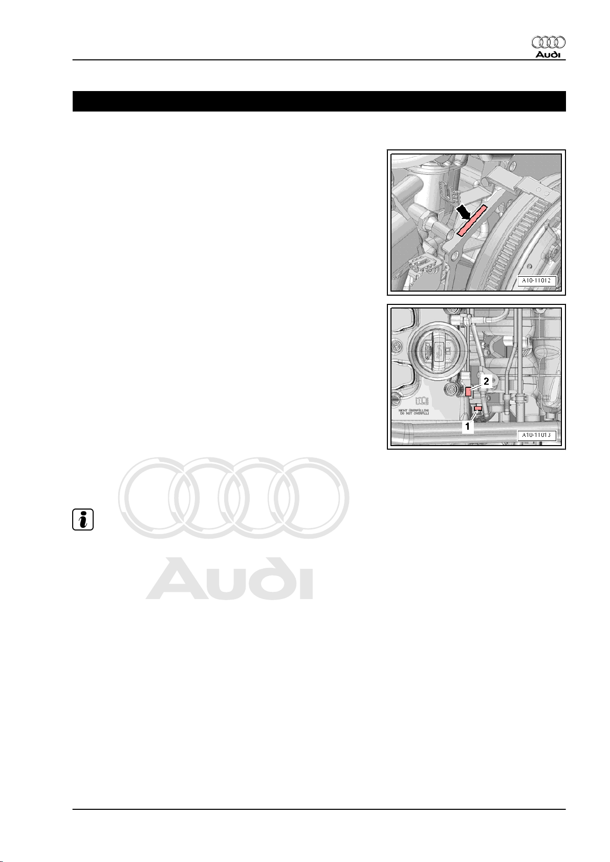
1 Engine number
♦ The engine number (“Engine code” and “Serial number”) can
be found on the left of the joint between engine and gearbox
-arrow-.
♦ The engine code letters are also stamped on the right of the
cylinder head -2- and on the cylinder block -1-.
♦ Additionally there is a sticker on the toothed belt cover with“En‐
gine code” and “Serial number”.
♦ Starting with the letter “C”, the engine codes consist of 4 let‐
ters.
♦ The first 3 characters of the engine code stand for the engine
capacity and the mechanical construction and design. They
are stamped on the cylinder block, together with the serial
number.
♦ The 4th character indicates the power output and torque of the
engine, and is determined by the engine control unit.
Note
♦
The 4-character engine code can be found on the type plate
(in versions for some countries only) and on the vehicle data
sticker and the engine control unit.
♦
Fitting locations of the type plate (certain countries only) and
the vehicle data sticker ⇒ Maintenance ; Booklet 810 .
1. Engine number 1
Page 8
Protected by copyright. Copying for private or commercial purposes, in part or in whole, is not
permitted unless authorised by AUDI AG. AUDI AG does not guarantee or accept any liability
with respect to the correctness of information in this document. Copyright by AUDI AG.
Audi TT 2007 ➤
4-cylinder direct petrol injection engine (2.0 ltr. 4-valve turbo TTS), mechanics - Edition 01.2008
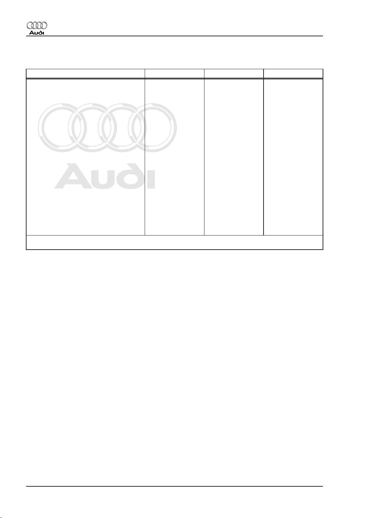
2 Engine data
Code letters CDLA CDLB CDMA
Capacity ltr. 1.984 1.984 1.984
Power output kW at rpm 195/6000 199/6000 195/6000
Torque Nm at rpm 350/2500 … 5250 350/2500 … 5250 350/2500 … 5250
Bore ∅ in mm 82.5 82.5 82.5
Stroke mm 92.8 92.8 92.8
Compression ratio
RON not less than
Firing order 1-3-4-2 1-3-4-2 1-3-4-2
Emission standards EU4 EU4 EU4
Exhaust gas recirculation no no no
Turbocharging/supercharging Turbocharger Turbocharger Turbocharger
Knock control yes yes yes
Charge air cooling yes yes yes
Lambda control 2 probes 2 probes 2 probes
Variable valve timing Inlet Inlet Inlet
Intake manifold change-over no no no
Secondary air system no no no
Valves per cylinder 4 4 4
1)
•
Unleaded premium RON 95 can also be used, but results in reduced power
9.8 9.8 9.8
98
1)
98
1)
98
1)
2 Rep. Gr.00 - Technical data
Page 9
Protected by copyright. Copying for private or commercial purposes, in part or in whole, is not
permitted unless authorised by AUDI AG. AUDI AG does not guarantee or accept any liability
with respect to the correctness of information in this document. Copyright by AUDI AG.
Audi TT 2007 ➤
4-cylinder direct petrol injection engine (2.0 ltr. 4-valve turbo TTS), mechanics - Edition 01.2008
3 Safety precautions
When working on the fuel system note the following warnings:
WARNING
The fuel system operates at extremely high pressure. This can
cause injury.
♦ The fuel pressure in the high-pressure section of the in‐
jection system must be reduced to a residual pressure
prior to opening the system.
♦ Wrap a clean cloth around the connection and carefully
loosen the connection to allow the residual pressure to
dissipate.
– Procedure before opening high-pressure section of injection
system ⇒ page 5 .
WARNING
Escaping fuel can cause a fire risk.
♦ The power supply for the fuel pump control unit -J538-
must be disconnected before opening the fuel system, as
the fuel system pressurisation pump -G6- will be activated
briefly when the driver's door is opened with the battery
still connected.
– Remove luggage compartment side trim (right-side) ⇒ Rep.
Gr. 70 .
3. Safety precautions 3
Page 10
Protected by copyright. Copying for private or commercial purposes, in part or in whole, is not
permitted unless authorised by AUDI AG. AUDI AG does not guarantee or accept any liability
with respect to the correctness of information in this document. Copyright by AUDI AG.
Audi TT 2007 ➤
4-cylinder direct petrol injection engine (2.0 ltr. 4-valve turbo TTS), mechanics - Edition 01.2008
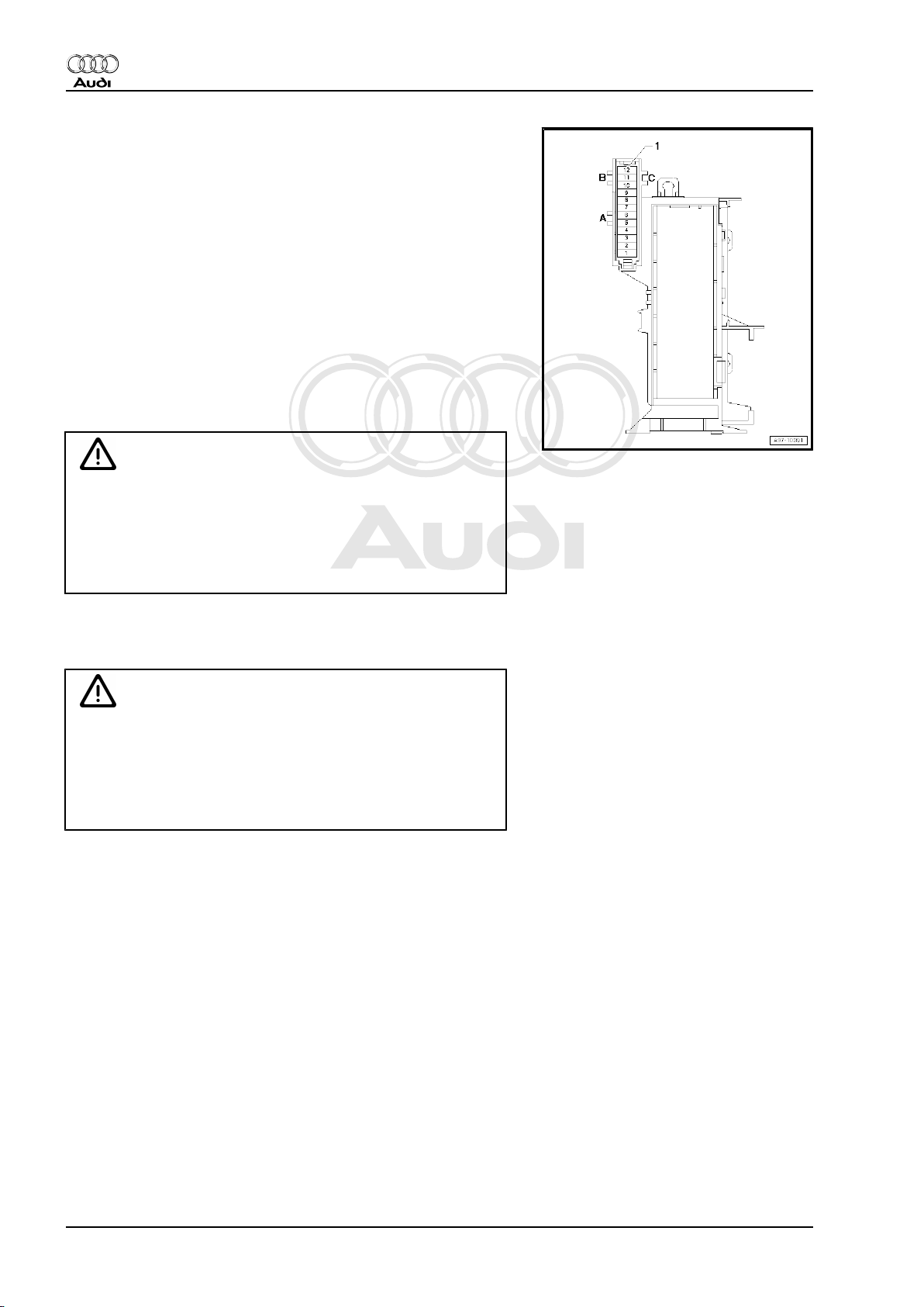
– Remove fuse 6 in fuse holder F -SF6- for fuel pump control
unit -J538- in fuse holder in luggage compartment (right-side).
Observe the following to prevent injuries to persons and damage
to the injection and ignition system:
♦ Always switch off the ignition before connecting or discon‐
necting electrical wiring for the injection or ignition system or
tester cables.
♦ Always switch off ignition before washing engine.
♦ Faults are stored in engine control unit if electrical connectors
have been unplugged:
– Connect vehicle diagnostic, testing and information system -
VAS 5051B- .
– Start “Guided Functions” mode.
– Generate readiness code in engine control unit.
Caution
To prevent damage to the electronic components when dis‐
connecting the battery:
♦ Observe notes on procedure for disconnecting the battery.
♦ Always switch off the ignition before disconnecting the
battery.
– Disconnect battery ⇒ Rep. Gr. 27 .
When working on the cooling system note the following warnings:
WARNING
Hot steam/hot coolant can escape - risk of scalding.
♦ The cooling system is under pressure when the engine is
hot.
♦ Cover filler cap on expansion tank with a cloth and open
carefully to dissipate pressure.
4 Rep. Gr.00 - Technical data
Page 11
Protected by copyright. Copying for private or commercial purposes, in part or in whole, is not
permitted unless authorised by AUDI AG. AUDI AG does not guarantee or accept any liability
with respect to the correctness of information in this document. Copyright by AUDI AG.
Audi TT 2007 ➤
4-cylinder direct petrol injection engine (2.0 ltr. 4-valve turbo TTS), mechanics - Edition 01.2008
Note the following if testers and measuring instruments have to
be used during a road test:
WARNING
Accidents can be caused if the driver is distracted by test
equipment while road-testing, or if test equipment is not prop‐
erly secured.
Injuries can also be caused if the passenger's airbag is trig‐
gered in a collision.
• The use of test equipment while driving causes distraction.
• There is an increased risk of injury if test equipment is not
secured.
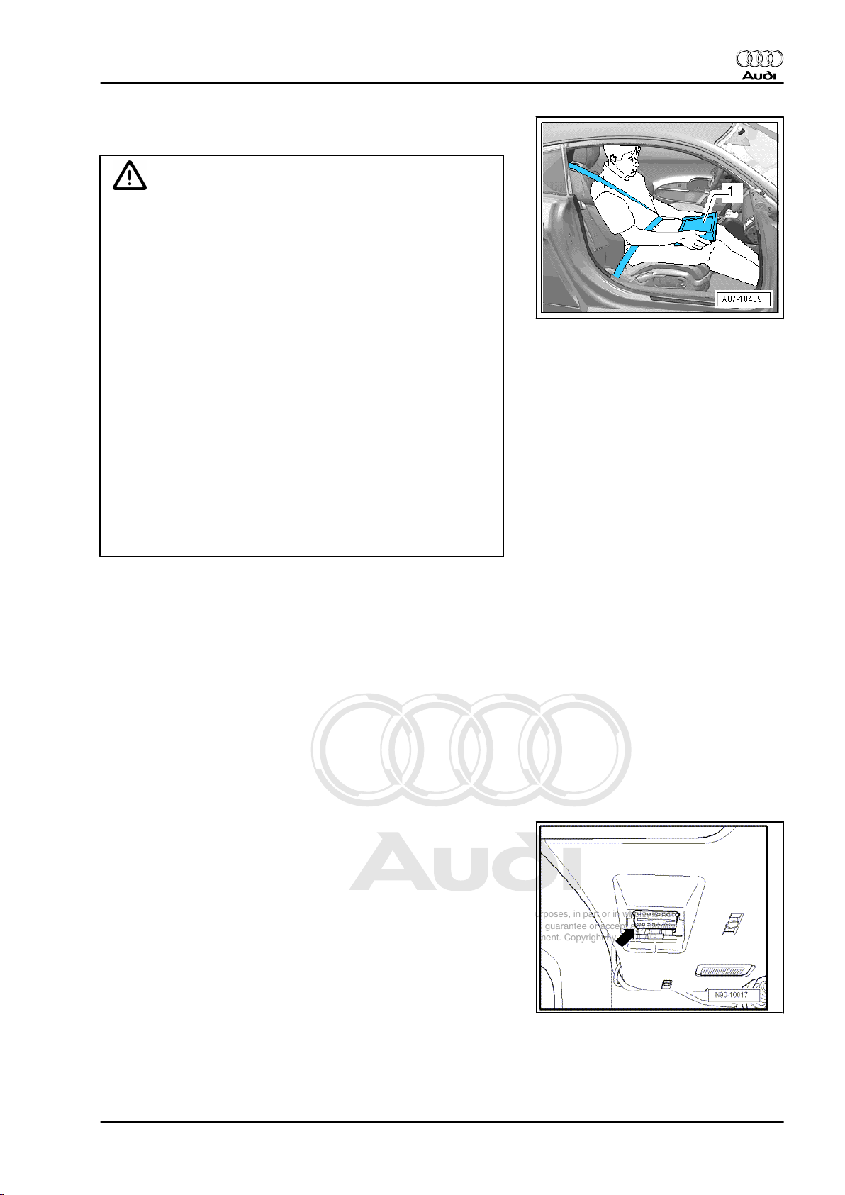
TT Coupé:
Test equipment must always be secured on the rear seat with
a strap and operated from the rear seat by a second person.
TT Roadster:
♦ Move the passenger's seat back as far as it will go.
♦ Use only vehicle diagnosis and service information sys‐
tem -VAS 5052- or diagnosis system -VAS 5053- .
♦ The test equipment -1- must rest flat on the passenger's
thighs (as shown in illustration) and must be operated by
the passenger.
3.1 Procedure before opening high-pres‐
sure section of injection system
♦ The injection system consists of a high-pressure section (max‐
imum approx. 120 bar) and a low-pressure section (approx.
6 bar).
♦ Before removing a component in the high-pressure section of
the injection system, the fuel pressure in the high-pressure
section must be reduced to a residual pressure of approx.
6 bar; follow the procedure outlined below.
Special tools and workshop equipment required
♦ Vehicle diagnostic, testing and information system -VAS
5051B-
Procedure
Proceed as follows:
– With ignition switched off, connect vehicle diagnostic, testing
and information system -VAS 5051B- with diagnosis lead to
diagnosis connection.
– Start the engine and run at idling speed.
3. Safety precautions 5
Page 12
Protected by copyright. Copying for private or commercial purposes, in part or in whole, is not
permitted unless authorised by AUDI AG. AUDI AG does not guarantee or accept any liability
with respect to the correctness of information in this document. Copyright by AUDI AG.
Audi TT 2007 ➤
4-cylinder direct petrol injection engine (2.0 ltr. 4-valve turbo TTS), mechanics - Edition 01.2008
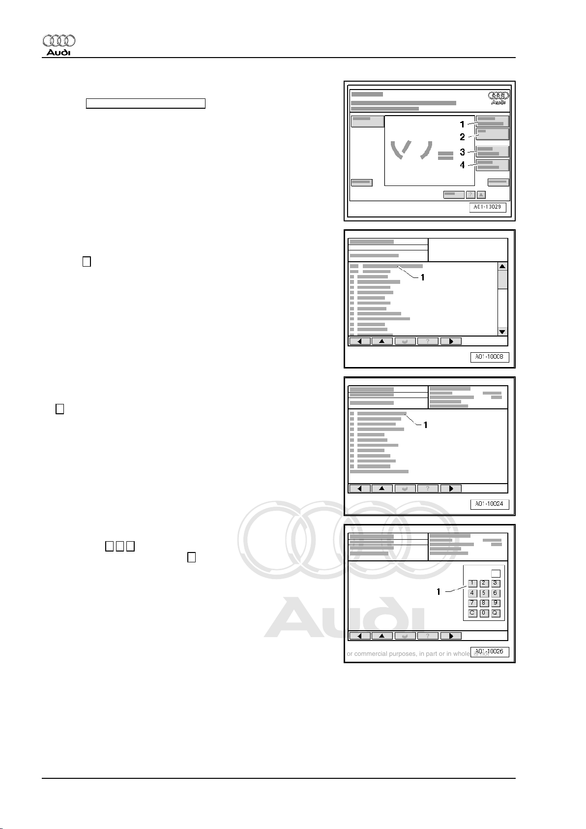
Display on -VAS 5051B- :
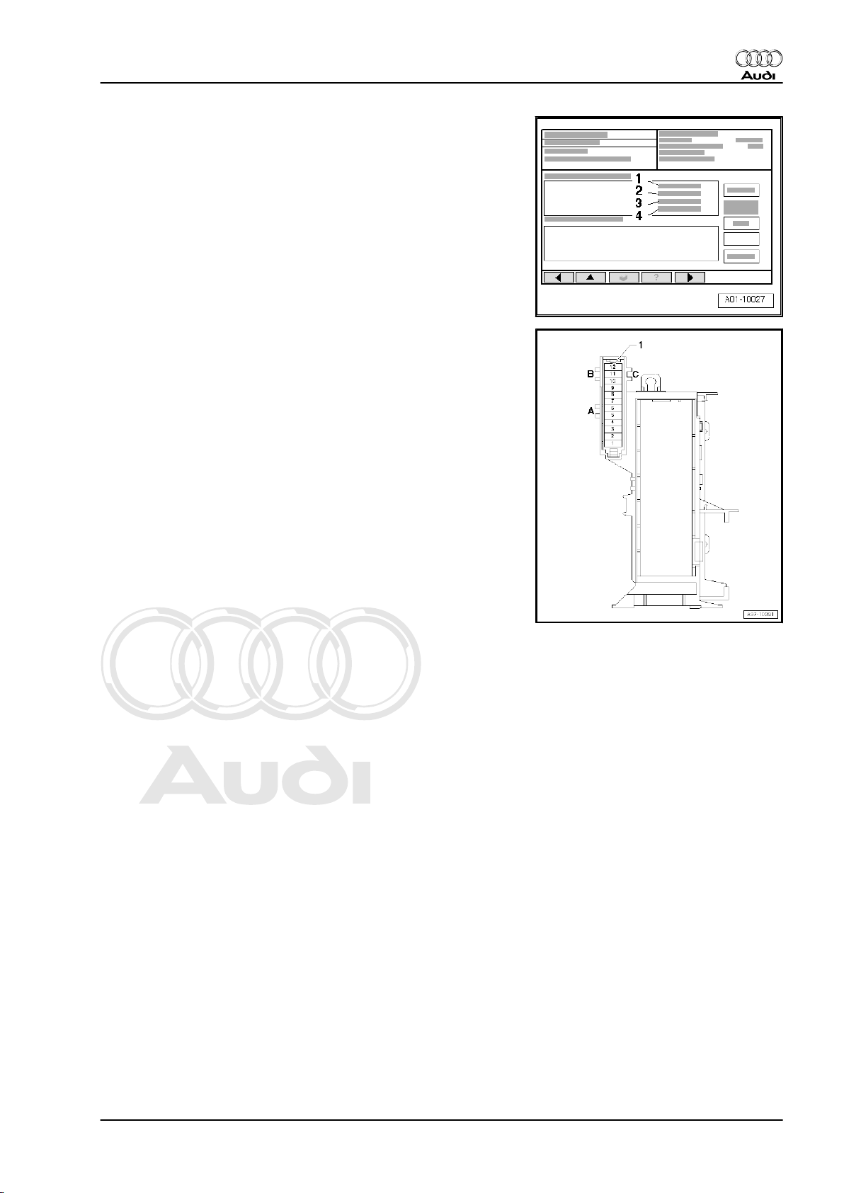
– Select Vehicle self-diagnosis from the list -item 1-.
Display on -VAS 5051B- :
– From menu -1-, select vehicle system “Engine electronics” and
press → key to continue.
Display on -VAS 5051B- :
– From menu -1-, select function “Measured values” and press
→ key to continue.
Display on -VAS 5051B- :
– Press keys 1 4 0 on keypad -1- to select “Display group 140”
and confirm entry by pressing Q
key.
6 Rep. Gr.00 - Technical data
Page 13
Protected by copyright. Copying for private or commercial purposes, in part or in whole, is not
permitted unless authorised by AUDI AG. AUDI AG does not guarantee or accept any liability
with respect to the correctness of information in this document. Copyright by AUDI AG.
Audi TT 2007 ➤
4-cylinder direct petrol injection engine (2.0 ltr. 4-valve turbo TTS), mechanics - Edition 01.2008
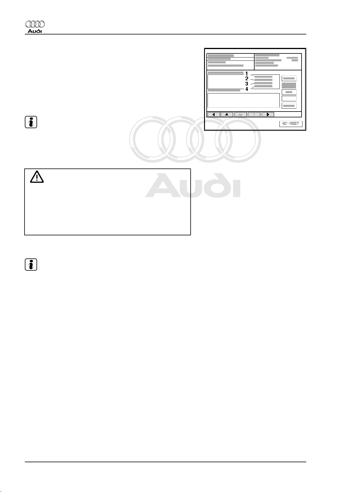
Display on -VAS 5051B- :
– Check display indicating fuel pressure in fuel rail in display
zone -3-.
• With engine idling the figure displayed will be 35 ... 45 bar. The
display shows the actual pressure in the fuel rail which is being
generated by the high-pressure pump.
– Remove luggage compartment side trim (right-side) ⇒ Rep.
Gr. 70 .
– Remove fuse 6 in fuse holder F -SF6- for fuel pump control
unit -J538- in fuse holder in luggage compartment (right-side).
3. Safety precautions 7
Page 14
Protected by copyright. Copying for private or commercial purposes, in part or in whole, is not
permitted unless authorised by AUDI AG. AUDI AG does not guarantee or accept any liability
with respect to the correctness of information in this document. Copyright by AUDI AG.
Audi TT 2007 ➤
4-cylinder direct petrol injection engine (2.0 ltr. 4-valve turbo TTS), mechanics - Edition 01.2008
Display on -VAS 5051B- :
– With engine still running, check display zone -3- for fuel pres‐
sure in fuel system:
• The fuel pressure will decrease very quickly because the me‐
chanical high-pressure pump is no longer being supplied with
fuel from the fuel tank by the electric fuel pump.
– Switch off ignition as soon as fuel pressure has dropped to just
below 8 bar.
Note
Fuel pressure must not fall below 6 bar, otherwise the engine will
stall (this could damage the catalytic converter).
The fuel rail is still filled with fuel, however it is no longer under
high pressure.
WARNING
There is a risk of injury: avoid skin contact with fuel.
♦ Wear safety goggles and protective clothing when open‐
ing the fuel system.
♦ Before opening the high-pressure section of the fuel sys‐
tem, place a clean cloth around the connection to catch
escaping fuel.
– Disconnect a fuel line connection without delay.
Note
The pressure will increase again due to the effect of residual heat
if the high-pressure system is not opened immediately.
Additional steps required
– Re-fit fuse 6 in fuse holder F -SF6- .
– With ignition switched off, connect vehicle diagnostic, testing
and information system -VAS 5051B- .
– Start “Guided Functions” mode.
– Generate readiness code in engine control unit ⇒ Vehicle di‐
agnosis, testing and information system VAS 5051.
8 Rep. Gr.00 - Technical data
Page 15

Protected by copyright. Copying for private or commercial purposes, in part or in whole, is not
permitted unless authorised by AUDI AG. AUDI AG does not guarantee or accept any liability
with respect to the correctness of information in this document. Copyright by AUDI AG.
Audi TT 2007 ➤
4-cylinder direct petrol injection engine (2.0 ltr. 4-valve turbo TTS), mechanics - Edition 01.2008
4 General repair instructions
4.1 Rules for cleanliness when working on fuel supply system, injection system and turbocharger
Even small amounts of dirt can cause malfunctions. For this rea‐
son, please observe the following rules when working on the fuel
supply system, injection system and turbocharger:
♦ Carefully clean connection points and the surrounding area
with engine cleaner or brake cleaner and dry thoroughly before
opening.
♦ Seal off open lines and connections with clean plugs or sealing
caps immediately.
♦ Place parts that have been removed on a clean surface and
cover them over. Use only lint-free cloths.
♦ Carefully cover or seal open components if repairs cannot be
carried out immediately.
♦ Only install clean components; replacement parts should only
be unpacked immediately prior to installation. Do not use parts
that have not been stored in their packing (e.g. in tool boxes
etc.).
♦ When the system is open, do not work with compressed air
and do not move the vehicle.
♦ Protect unplugged electrical connectors against dirt and mois‐
ture and make sure connections are dry when attaching.
4.2 Contact corrosion!
Contact corrosion can occur if unsuitable fasteners are used (e.g.
bolts, nuts, washers, etc.).
For this reason, only fasteners with a special surface coating are
used.
Additionally, all rubber and plastic parts and all adhesives are
made of non-conductive materials.
Always install new parts if you are not sure whether used parts
can be re-fitted ⇒ Electronic parts catalogue .
Note the following:
♦ We recommend using only genuine replacement parts; these
have been tested and are compatible with aluminium.
♦ We recommend the use of Audi accessories.
♦ Damage caused by contact corrosion is not covered under
warranty.
4.3 Routing and attachment of pipes, hoses and wiring
Mark hydraulic lines, vacuum lines and electrical wiring before
removal so they can be re-installed in the original positions and
correctly connected. Make sketches or take photographs if nec‐
essary.
4. General repair instructions 9
Page 16
Protected by copyright. Copying for private or commercial purposes, in part or in whole, is not
permitted unless authorised by AUDI AG. AUDI AG does not guarantee or accept any liability
with respect to the correctness of information in this document. Copyright by AUDI AG.
Audi TT 2007 ➤
4-cylinder direct petrol injection engine (2.0 ltr. 4-valve turbo TTS), mechanics - Edition 01.2008
10 – Removing and installing engine
1 Removing engine
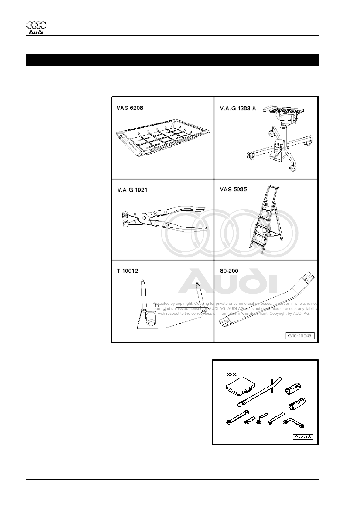
Special tools and workshop
equipment required
♦ Drip tray for workshop hoist
-VAS 6208-
♦ Engine and gearbox jack -
V.A.G 1383 A-
♦ Hose clip pliers -V.A.G
1921-
♦ Stepladder -VAS 5085-
♦ Engine bracket -T10012-
♦ Removal lever -80 - 200-
♦ Lambda probe open ring spanner set -3337-
10 Rep. Gr.10 - Removing and installing engine
Page 17
Protected by copyright. Copying for private or commercial purposes, in part or in whole, is not
permitted unless authorised by AUDI AG. AUDI AG does not guarantee or accept any liability
with respect to the correctness of information in this document. Copyright by AUDI AG.
Audi TT 2007 ➤
4-cylinder direct petrol injection engine (2.0 ltr. 4-valve turbo TTS), mechanics - Edition 01.2008
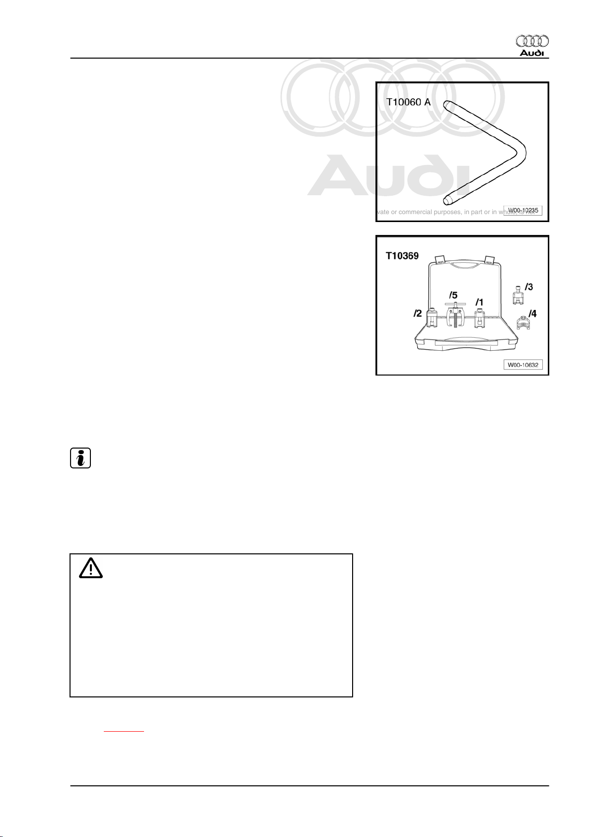
♦ Locking pin -T10060A-
♦ Tool set for wiper arms -T10369-
♦ Engine bung set -VAS 6122-
Procedure
Proceed as follows:
Note
♦
The engine is removed from underneath together with the
gearbox.
♦
Fit cable ties in the original positions when installing.
♦
Collect drained coolant in a clean container for re-use or dis‐
posal.
WARNING
The fuel system operates at extremely high pressure. This can
cause injury.
♦ Do not open the high-pressure section of the injection
system when removing the engine.
♦ However, if the engine has to be removed for repair pro‐
cedures which necessitate opening the high-pressure
section, the fuel pressure in the high-pressure section
must be reduced in a controlled manner to a residual pres‐
sure prior to opening.
– Reduce fuel pressure in high-pressure section of injection sys‐
tem ⇒ page 5 .
1. Removing engine 11
Page 18
Protected by copyright. Copying for private or commercial purposes, in part or in whole, is not
permitted unless authorised by AUDI AG. AUDI AG does not guarantee or accept any liability
with respect to the correctness of information in this document. Copyright by AUDI AG.
Audi TT 2007 ➤
4-cylinder direct petrol injection engine (2.0 ltr. 4-valve turbo TTS), mechanics - Edition 01.2008
Caution
To prevent damage to the electronic components when dis‐
connecting the battery:
♦ Observe notes on procedure for disconnecting the battery.
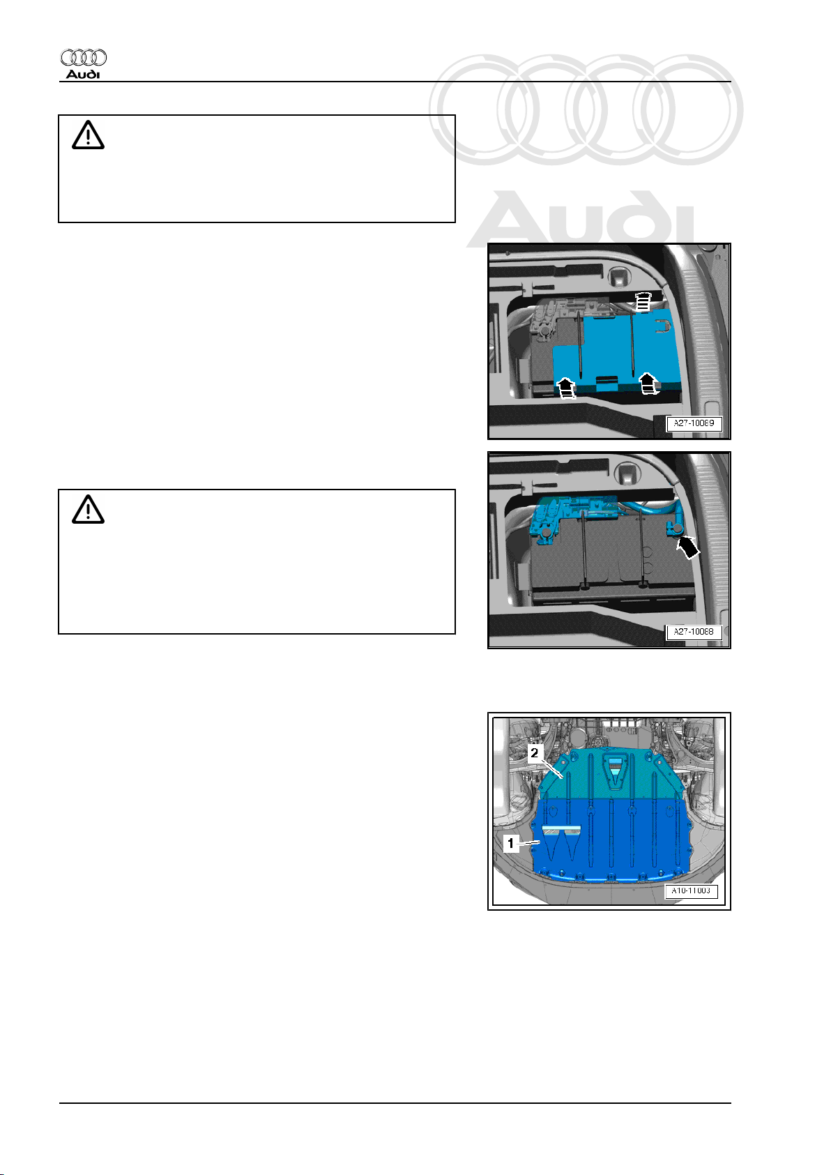
– Take out luggage compartment floor covering.
– Remove rear cross panel trim if cover for negative terminal of
battery is located under rear cross panel trim ⇒ Rep. Gr. 70 .
– Release retaining clips -arrows- and detach cover for negative
terminal.
– Slacken nut a few turns and disconnect battery clamp on earth
cable -arrow- from battery terminal.
WARNING
Hot steam/hot coolant can escape - risk of scalding.
♦ The cooling system is under pressure when the engine is
hot.
♦ Cover filler cap on expansion tank with a cloth and open
carefully to dissipate pressure.
– Open filler cap on expansion tank.
– Remove both front wheels.
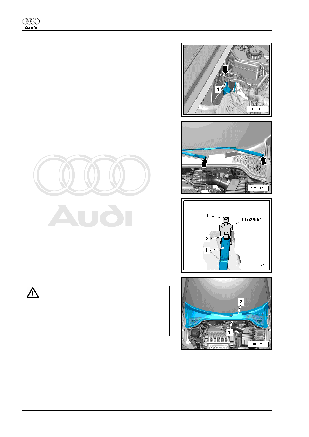
– Remove front noise insulation -1- ⇒ Rep. Gr. 66 .
12 Rep. Gr.10 - Removing and installing engine
Page 19
Protected by copyright. Copying for private or commercial purposes, in part or in whole, is not
permitted unless authorised by AUDI AG. AUDI AG does not guarantee or accept any liability
with respect to the correctness of information in this document. Copyright by AUDI AG.
Audi TT 2007 ➤
4-cylinder direct petrol injection engine (2.0 ltr. 4-valve turbo TTS), mechanics - Edition 01.2008
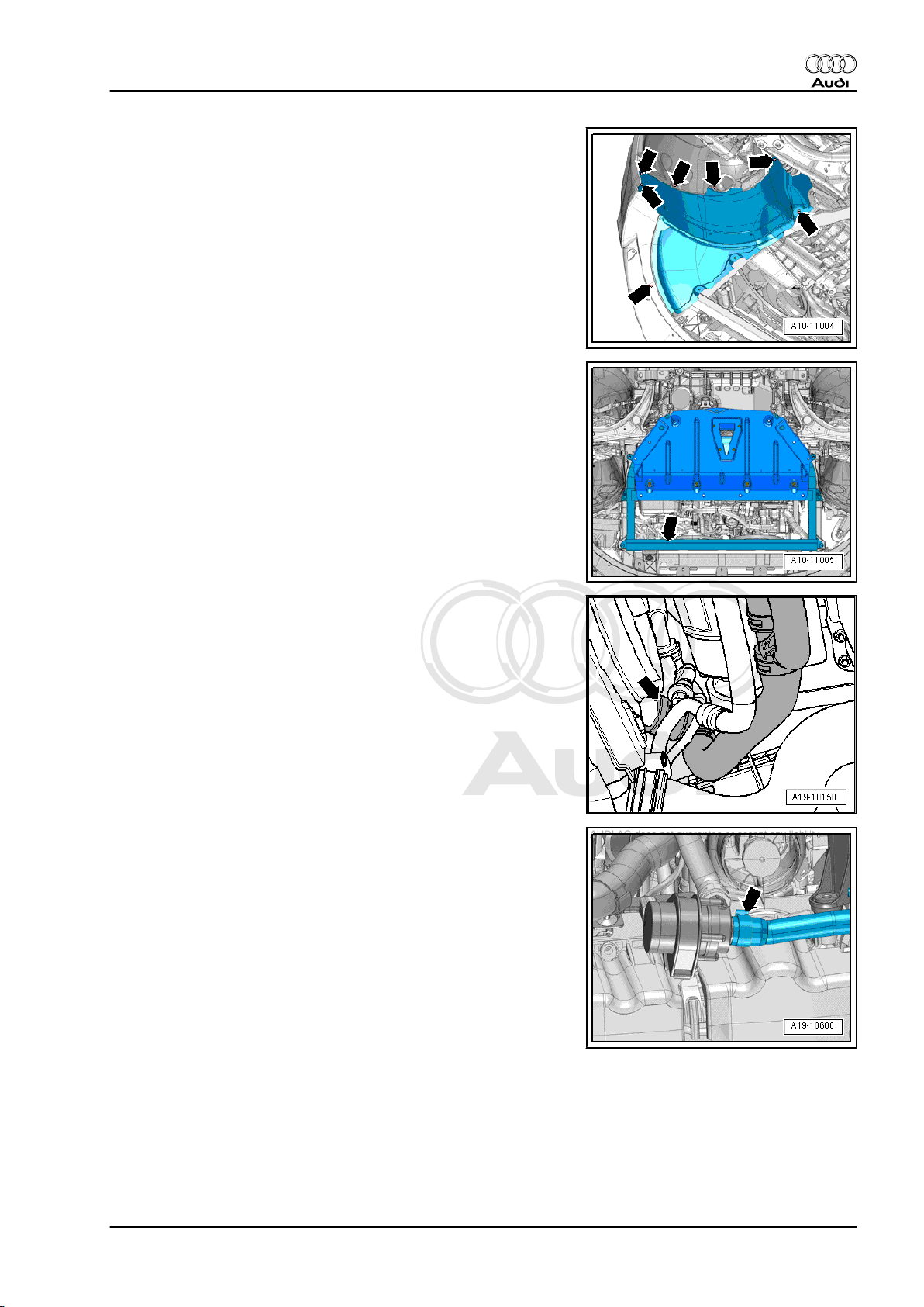
– Remove noise insulation on left and right sides -arrows-.
– Remove noise insulation frame -arrow- together with rear
noise insulation ⇒ Rep. Gr. 66 .
– Place drip tray for workshop hoist -VAS 6208- beneath engine.
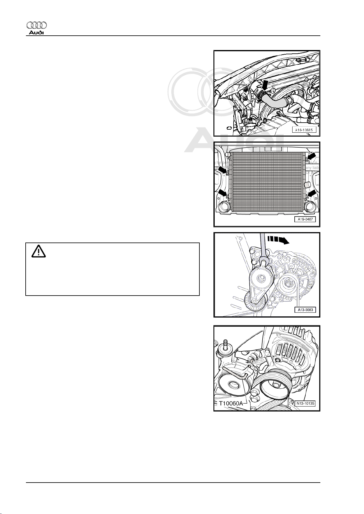
– Lift retaining clip, disconnect coolant hose (bottom) -arrow-
from radiator and drain off coolant.
– Disconnect bottom coolant hose leading to continued coolant
circulation pump -V51- -arrow- and drain off coolant.
1. Removing engine 13
Page 20
Protected by copyright. Copying for private or commercial purposes, in part or in whole, is not
permitted unless authorised by AUDI AG. AUDI AG does not guarantee or accept any liability
with respect to the correctness of information in this document. Copyright by AUDI AG.
Audi TT 2007 ➤
4-cylinder direct petrol injection engine (2.0 ltr. 4-valve turbo TTS), mechanics - Edition 01.2008
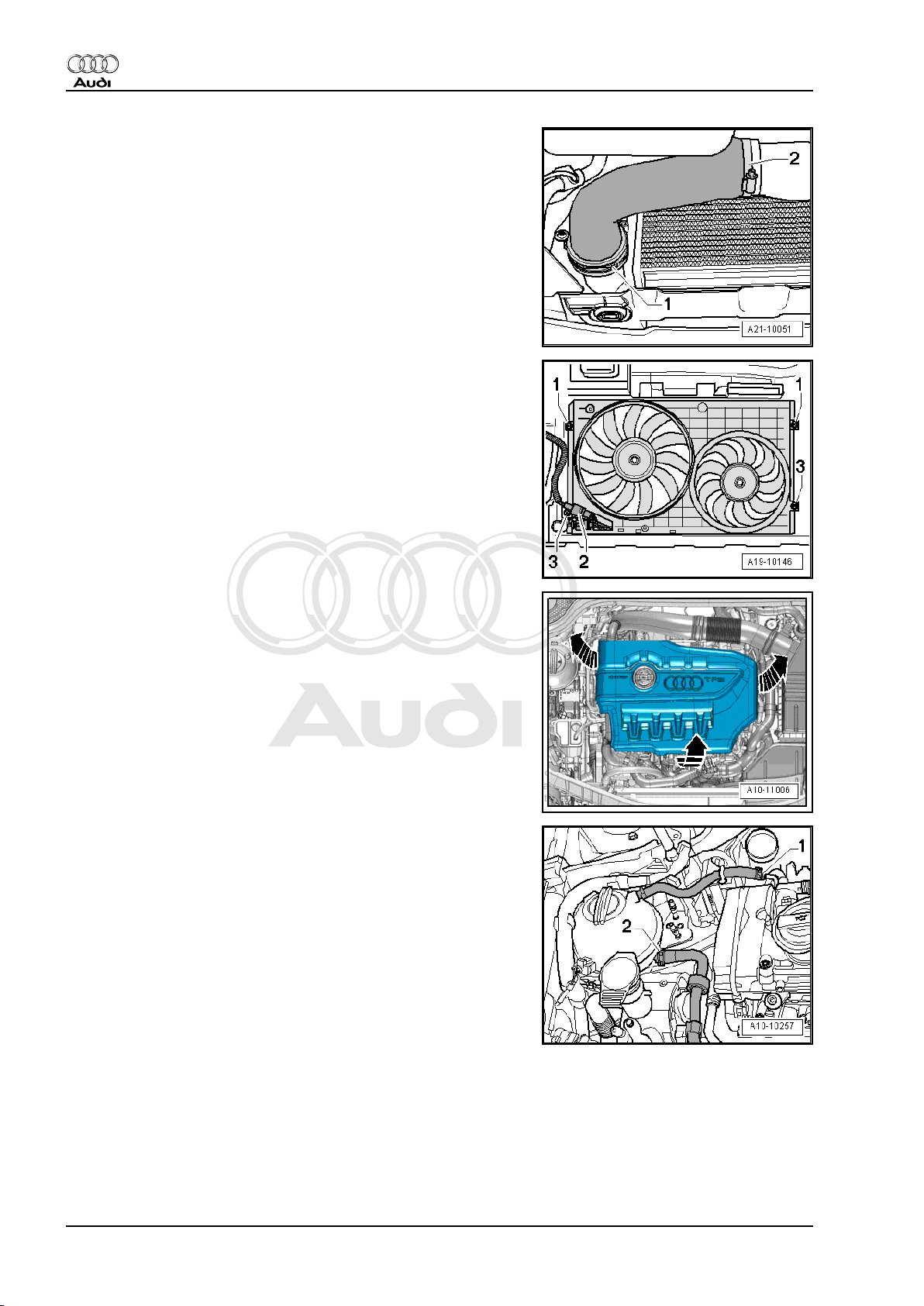
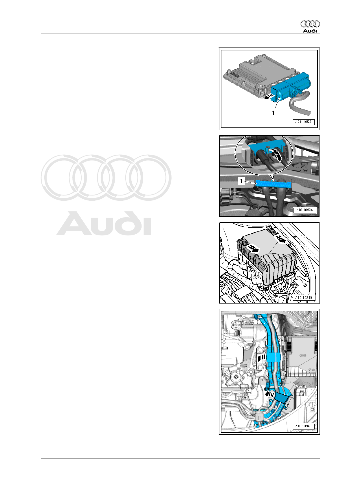
– Release hose clips -1- and -2- and remove air hose.
– Unplug electrical connector -2-.
– Remove bolts -3-.
– Remove engine cover panel -arrows-.
– Detach coolant hoses -1- and -2-.
14 Rep. Gr.10 - Removing and installing engine
Page 21
Protected by copyright. Copying for private or commercial purposes, in part or in whole, is not
permitted unless authorised by AUDI AG. AUDI AG does not guarantee or accept any liability
with respect to the correctness of information in this document. Copyright by AUDI AG.
Audi TT 2007 ➤
4-cylinder direct petrol injection engine (2.0 ltr. 4-valve turbo TTS), mechanics - Edition 01.2008
WARNING
Risk of injury caused by fuel.
♦ To allow the fuel pressure to dissipate, wrap a clean cloth
around the connection and carefully loosen the connec‐
tion before opening the fuel system.
Caution
Observe rules for cleanliness when working on the fuel supply
system ⇒ page 9 .
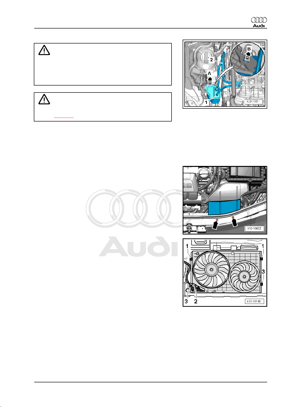
– Remove protective sleeve -2- and disconnect fuel hose by
pressing release ring.
– Detach hose -1-.
– Release activated charcoal filter -arrow B-, lift off -arrow A- and
move clear to one side.
– Unscrew bolts -arrows- and remove air duct.
– Remove bolts -1- and lift out radiator cowl.
1. Removing engine 15
Page 22
Protected by copyright. Copying for private or commercial purposes, in part or in whole, is not
permitted unless authorised by AUDI AG. AUDI AG does not guarantee or accept any liability
with respect to the correctness of information in this document. Copyright by AUDI AG.
Audi TT 2007 ➤
4-cylinder direct petrol injection engine (2.0 ltr. 4-valve turbo TTS), mechanics - Edition 01.2008
– Lift retaining clip and disconnect coolant hose (top) -arrow-
from radiator.
– Remove bolts -arrows- on reverse side of radiator.
– Remove radiator upwards.
Vehicles with air conditioning:
Caution
If a used belt runs in the opposite direction when it is refitted,
this can cause breakage.
♦ Before removing, mark direction of rotation of poly V-belt
with chalk or felt-tipped pen for re-installation.
– To slacken poly V-belt turn tensioner in clockwise direction
-arrow-.
– Lock tensioner with locking pin -T10060 A-
– Take off poly V-belt.
16 Rep. Gr.10 - Removing and installing engine
Page 23
Protected by copyright. Copying for private or commercial purposes, in part or in whole, is not
permitted unless authorised by AUDI AG. AUDI AG does not guarantee or accept any liability
with respect to the correctness of information in this document. Copyright by AUDI AG.
Audi TT 2007 ➤
4-cylinder direct petrol injection engine (2.0 ltr. 4-valve turbo TTS), mechanics - Edition 01.2008
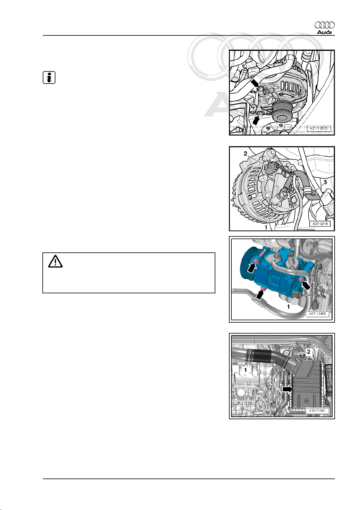
– Remove bolts -arrows- and detach alternator from bracket for
ancillaries.
Note
♦
If alternator sticks in its bracket, screw bolt back in again down
to the last 2 turns.
♦
Tap carefully on bolt heads with flat side of hammer to release
bushes of alternator mountings.
– Swivel alternator towards right side of vehicle with electrical
wiring connected.
– Unplug electrical connector -2-.
– Unscrew electrical wiring -1- and clamp -3- and remove from
alternator.
– Lift out alternator.
– Unplug electrical connector -1- for magnetic clutch on air con‐
ditioner compressor.
Caution
Danger of damage to refrigerant lines and hoses.
♦ Do NOT stretch, kink or bend refrigerant lines and hoses.
– Remove bolts -arrows-.
– Detach air conditioner compressor from bracket for ancillaries
and tie up to the right side.
All vehicles (continued):
– Release hose clip -1- and detach air hose.
– Unplug electrical connector -2- for air mass meter -G70- .
– Unscrew top section of air cleaner housing -arrow- and re‐
move air filter element.
1. Removing engine 17
Page 24
Protected by copyright. Copying for private or commercial purposes, in part or in whole, is not
permitted unless authorised by AUDI AG. AUDI AG does not guarantee or accept any liability
with respect to the correctness of information in this document. Copyright by AUDI AG.
Audi TT 2007 ➤
4-cylinder direct petrol injection engine (2.0 ltr. 4-valve turbo TTS), mechanics - Edition 01.2008
– Remove bolts -arrows- and detach bottom section of air clean‐
er housing.
– Remove bolts -arrows- and detach bracket for air cleaner
housing.
– Take electrical connector -arrow- for Lambda probe -G39- out
of bracket, unplug and move clear.
– Unscrew Lambda probe -G39- -arrow- using tool from Lambda
probe open ring spanner set -3337- .
18 Rep. Gr.10 - Removing and installing engine
Page 25
Protected by copyright. Copying for private or commercial purposes, in part or in whole, is not
permitted unless authorised by AUDI AG. AUDI AG does not guarantee or accept any liability
with respect to the correctness of information in this document. Copyright by AUDI AG.
Audi TT 2007 ➤
4-cylinder direct petrol injection engine (2.0 ltr. 4-valve turbo TTS), mechanics - Edition 01.2008
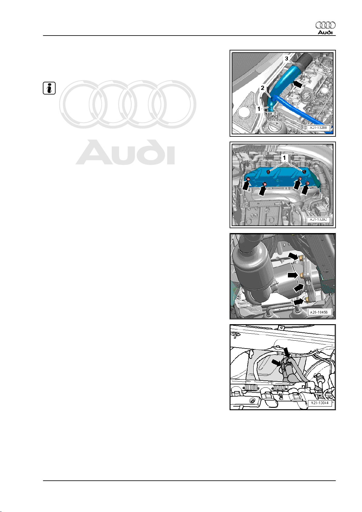
– Remove bolt -arrow-.
– Release hose clip -1- and lay air pipe on engine (hose -2- re‐
mains attached).
Note
Disregard item -3-.
– Unscrew bolts -arrows- and nuts -1- and detach heat shield.
– Working from above, unscrew nuts -arrows- securing front ex‐
haust pipe to turbocharger.
– Detach coolant hoses -arrows- leading to heat exchanger.
1. Removing engine 19
Page 26
Protected by copyright. Copying for private or commercial purposes, in part or in whole, is not
permitted unless authorised by AUDI AG. AUDI AG does not guarantee or accept any liability
with respect to the correctness of information in this document. Copyright by AUDI AG.
Audi TT 2007 ➤
4-cylinder direct petrol injection engine (2.0 ltr. 4-valve turbo TTS), mechanics - Edition 01.2008
– Disconnect vacuum hose -1- coming from non-return valve.
– Pull non-return valve -arrow- off brake servo.
– Pry off caps on windscreen wiper arms with a screwdriver.
– Loosen nuts -arrows- several turns.
– Apply puller -T10369/1- to wiper arm -1- as shown in illustra‐
tion.
– Apply thrust piece -2- onto wiper shaft.
– Turn bolt -3- in clockwise direction until wiper arm is pulled off
wiper shaft.
– Remove nuts and detach windscreen wiper arms.
– Remove seal -1-.
Caution
Risk of damage to plenum chamber cover.
♦ Apply a small quantity of soap solution to transition be‐
tween windscreen and plenum chamber cover -2-. Then,
starting at edge of windscreen, carefully pull plenum
chamber cover upwards off retainer at windscreen.
– Detach plenum chamber cover -2- by pulling it carefully off re‐
tainer at windscreen.
– Detach engine wiring harness (rear) at plenum chamber par‐
tition panel.
20 Rep. Gr.10 - Removing and installing engine
Page 27
Protected by copyright. Copying for private or commercial purposes, in part or in whole, is not
permitted unless authorised by AUDI AG. AUDI AG does not guarantee or accept any liability
with respect to the correctness of information in this document. Copyright by AUDI AG.
Audi TT 2007 ➤
4-cylinder direct petrol injection engine (2.0 ltr. 4-valve turbo TTS), mechanics - Edition 01.2008
– Remove engine control unit ⇒ Rep. Gr. 24 .
– Unplug electrical connector -1- for engine wiring harness
-arrow-.
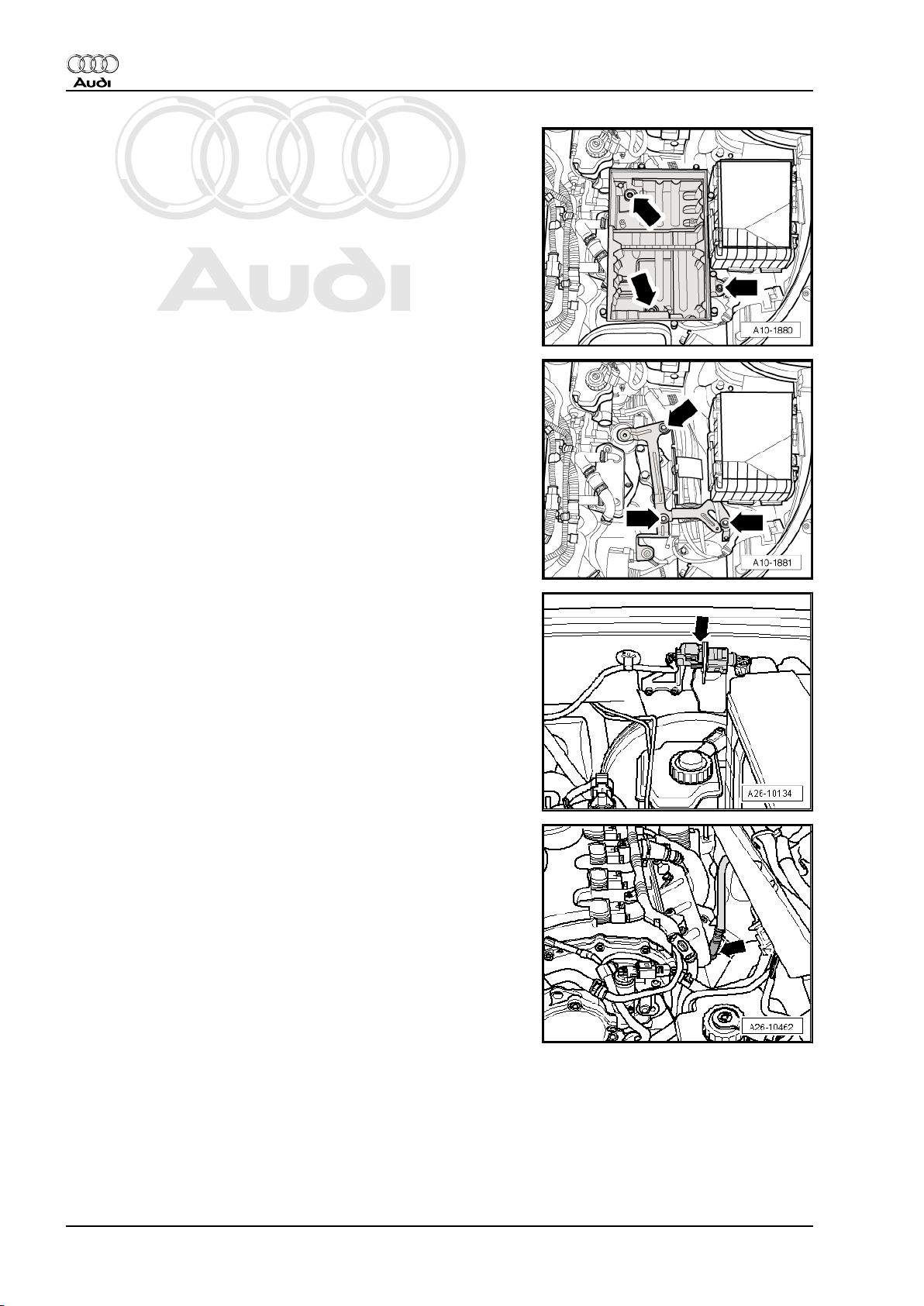
– Release wiring protector -1- for engine wiring harness
-arrow- and lift off.
– Slide the two clips in the direction of the -arrows- and remove
cover from electronics box in engine compartment.
– Open wiring duct brackets -arrows-.
1. Removing engine 21
Page 28
Protected by copyright. Copying for private or commercial purposes, in part or in whole, is not
permitted unless authorised by AUDI AG. AUDI AG does not guarantee or accept any liability
with respect to the correctness of information in this document. Copyright by AUDI AG.
Audi TT 2007 ➤
4-cylinder direct petrol injection engine (2.0 ltr. 4-valve turbo TTS), mechanics - Edition 01.2008
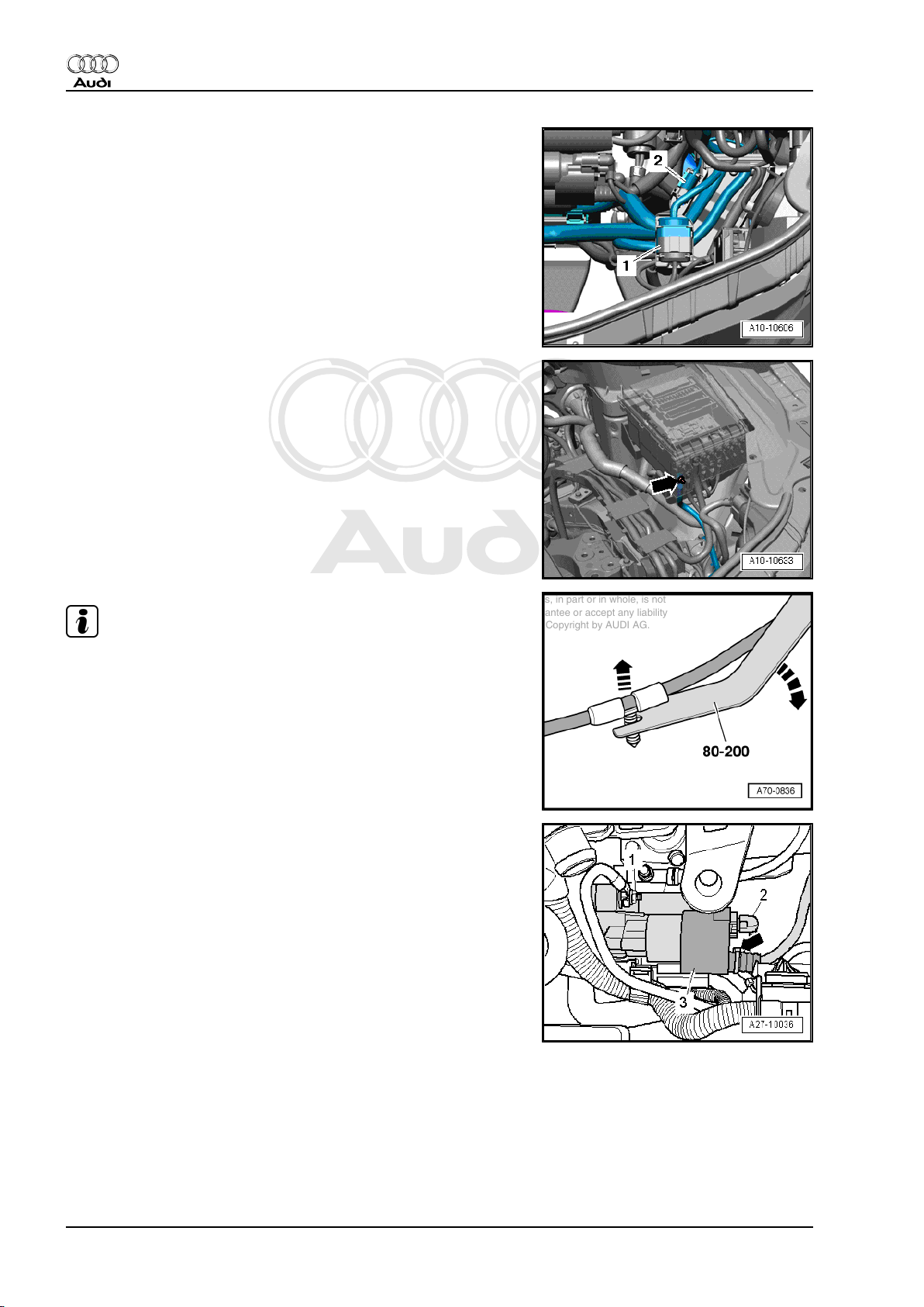
– Unclip electrical connector -1- from bracket and unplug.
– Open wiring duct bracket located underneath.
– Unclip wiring harness for engine control unit from wiring duct.
– Place engine wiring harness with engine control unit on top of
engine.
– Secure engine control unit to prevent it falling.
– Unclip electrical connector -2- from bracket and unplug.
– Unscrew terminal 30 wire -arrow- from electronics box in en‐
gine compartment and move it clear.
Note
Use removal lever -80 - 200- to lever out the wiring clips.
Vehicles with manual gearbox:
– Cut open cable tie -arrow- for protective cover -3-.
– Unplug electrical connector -2-.
– Push back protective cover and unscrew B+ cable at starter
solenoid switch
– Remove nut -1- for earth wire.
– Remove top starter bolt.
22 Rep. Gr.10 - Removing and installing engine
Page 29
Protected by copyright. Copying for private or commercial purposes, in part or in whole, is not
permitted unless authorised by AUDI AG. AUDI AG does not guarantee or accept any liability
with respect to the correctness of information in this document. Copyright by AUDI AG.
Audi TT 2007 ➤
4-cylinder direct petrol injection engine (2.0 ltr. 4-valve turbo TTS), mechanics - Edition 01.2008
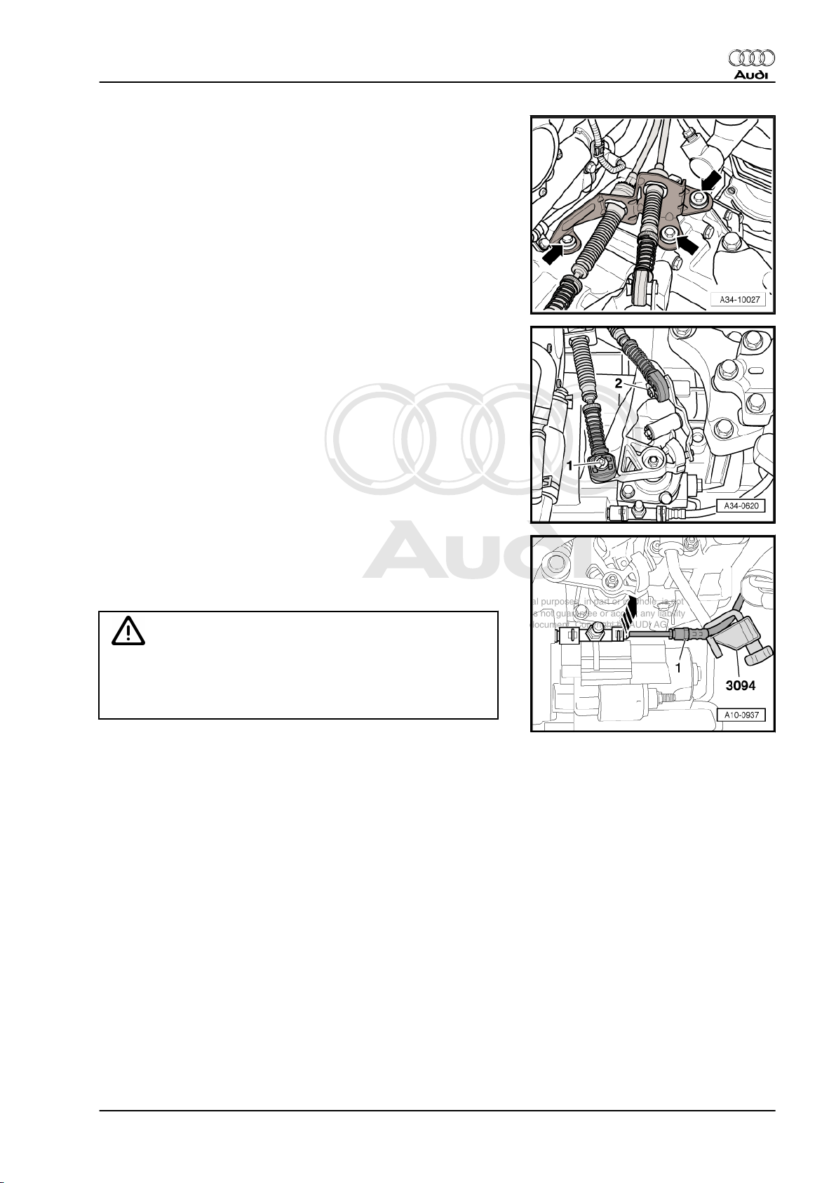
– Detach cable support bracket from gearbox -arrows-.
– Unclip circlip -1- from gear selector cable and circlip -2- from
gate selector cable.
– Pull selector cable end-pieces with selector cables off selector
shaft lever and relay lever.
– Tie selector cables with cable support bracket to one side.
– Clamp off pressure hose to clutch slave cylinder using a hose
clamp -3094- .
– Pull securing clip upwards -arrow- and detach pipe/hose as‐
sembly -1- from bleeder connection on clutch slave cylinder.
Caution
Risk of contamination by escaping brake fluid.
♦ Do not operate clutch pedal after detaching pipe/hose as‐
sembly from bleeder connection on clutch slave cylinder.
1. Removing engine 23
Page 30
Protected by copyright. Copying for private or commercial purposes, in part or in whole, is not
permitted unless authorised by AUDI AG. AUDI AG does not guarantee or accept any liability
with respect to the correctness of information in this document. Copyright by AUDI AG.
Audi TT 2007 ➤
4-cylinder direct petrol injection engine (2.0 ltr. 4-valve turbo TTS), mechanics - Edition 01.2008
Vehicles with S tronic gearbox:
– Cut open cable tie -arrow- for protective cover -1-.
– Unplug electrical connector -2-.
– Push back protective cover and unscrew B+ cable at starter
solenoid switch
– Unscrew earth wire -3-.
Caution
Risk of damage to control unit (mechatronic unit) by static dis‐
charge.
♦ Do NOT touch connector contacts in gearbox connector
with your hands.
– Touch vehicle earth with bare hands to discharge any static
charge.
– Turn retainer catch anti-clockwise and unplug electrical con‐
nector -4- at gearbox.
– Unplug electrical connector -1-.
Note
Disregard -arrows-.
All vehicles (continued):
– Loosen bolts -arrows- for assembly mounting (engine end)
approx. 2 turns.
– Loosen bolts -arrows- for assembly mounting (gearbox end)
approx. 2 turns.
24 Rep. Gr.10 - Removing and installing engine
Page 31

Protected by copyright. Copying for private or commercial purposes, in part or in whole, is not
permitted unless authorised by AUDI AG. AUDI AG does not guarantee or accept any liability
with respect to the correctness of information in this document. Copyright by AUDI AG.
Audi TT 2007 ➤
4-cylinder direct petrol injection engine (2.0 ltr. 4-valve turbo TTS), mechanics - Edition 01.2008
– Mark position of flexible coupling and flange for bevel box in
relation to each other for re-installation.
– Remove bolts -arrows- for flexible coupling for propshaft at
bevel box (counterhold using a suitable lever at the triangular
flange).
Caution
Make sure not to damage the oil seal -arrow- in the propshaft
flange.
♦ Push the propshaft horizontally to the rear and towards the
right side of vehicle as far as possible.
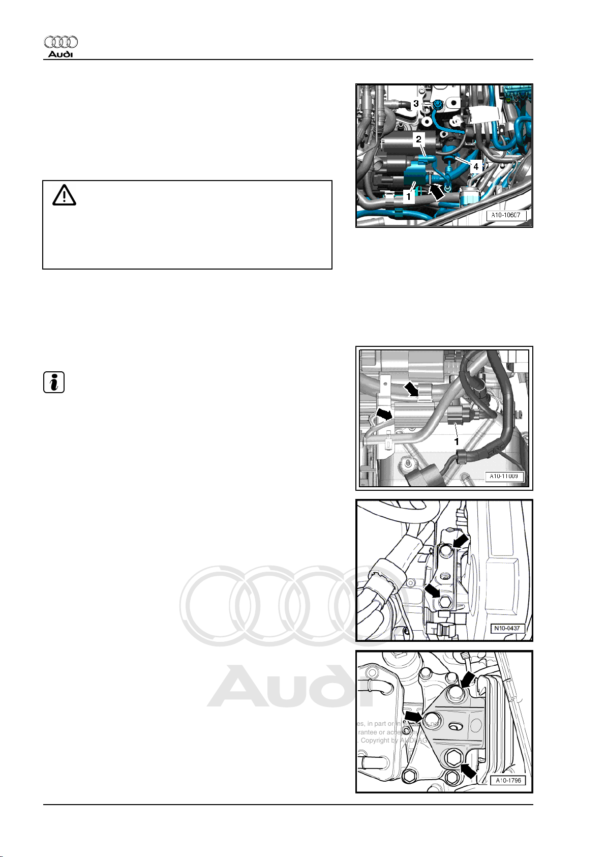
– Unscrew bolts -1- and -2- at bracket for electrical connector
for Lambda probe (on underbody) and remove cover.
– Remove bolt -3- and move electrical wire to Lambda probe
clear.
– Take plug-in connector -arrow- out of bracket.
– Unplug electrical connector for Lambda probe after catalytic
converter -G130- and move clear.
1. Removing engine 25
Page 32

Protected by copyright. Copying for private or commercial purposes, in part or in whole, is not
permitted unless authorised by AUDI AG. AUDI AG does not guarantee or accept any liability
with respect to the correctness of information in this document. Copyright by AUDI AG.
Audi TT 2007 ➤
4-cylinder direct petrol injection engine (2.0 ltr. 4-valve turbo TTS), mechanics - Edition 01.2008
– Remove bolts -arrows- and detach bracket for exhaust system
and tunnel brace.
Caution
Avoid damage to flexible joints.
♦ Do not bend flexible joints in front exhaust pipe more than
10°.
– Slacken nuts -arrows- at clamp and disconnect exhaust sys‐
tem.
– Detach front exhaust pipe with catalytic converter and front
silencer.
Vehicles with S tronic gearbox:
– Remove bolts -1- for support bracket.
– Pull off securing clip -3- -arrow- and remove selector lever ca‐
ble from gearbox.
Note
Disregard item -2-.
All vehicles (continued):
Caution
Make sure not to damage the oil seal in the propshaft flange.
♦ When removing the bolts for the pendulum support/sub‐
frame, the engine/gearbox assembly swings slightly for‐
ward.
– Remove bolts -1, 2, 3- and remove pendulum support.
26 Rep. Gr.10 - Removing and installing engine
Page 33

Protected by copyright. Copying for private or commercial purposes, in part or in whole, is not
permitted unless authorised by AUDI AG. AUDI AG does not guarantee or accept any liability
with respect to the correctness of information in this document. Copyright by AUDI AG.
Audi TT 2007 ➤
4-cylinder direct petrol injection engine (2.0 ltr. 4-valve turbo TTS), mechanics - Edition 01.2008
– Unplug electrical connector -1- at oil level and oil temperature
sender -G266- .
– Unclip bracket -2- for wire to oil level and oil temperature
sender -G266- from subframe.
– Unbolt heat shield for drive shaft (right-side) from bevel box
-arrows-.
– Unbolt drive shaft (left-side) from gearbox flange and drive
shaft (right-side) from bevel box flange.
– Release hose clip -arrow- and detach air hose from charge air
cooler.
– Move coolant hose -2- clear.
– Unscrew bolts -4- and move continued coolant circulation
pump -V51- to one side (coolant hoses -arrows- remain con‐
nected).
Note
Disregard -items 1 and 3-.
1. Removing engine 27
Page 34

Protected by copyright. Copying for private or commercial purposes, in part or in whole, is not
permitted unless authorised by AUDI AG. AUDI AG does not guarantee or accept any liability
with respect to the correctness of information in this document. Copyright by AUDI AG.
Audi TT 2007 ➤
4-cylinder direct petrol injection engine (2.0 ltr. 4-valve turbo TTS), mechanics - Edition 01.2008
– Secure engine bracket -T10012- to cylinder block with bolt
-1- and nut -2- (tightening torque: approx. 20 Nm).
– Insert engine and gearbox jack -V.A.G 1383 A- in engine sup‐
port -T10012- and raise engine/gearbox assembly slightly.
Note
To unscrew bolts for assembly mounting use stepladder VAS 5085- .
– Remove bolts -arrows- for assembly mounting (engine end).
– Remove bolts -arrows- for assembly mounting (gearbox end).
Note
♦
Check that all hoses, pipes and wiring connections between
engine, gearbox and body have been detached.
♦
Carefully guide engine/gearbox assembly when lowering to
avoid damage.
– Pull engine/gearbox assembly as far forward and to the left as
possible, and lower gradually (pay attention to drive shafts).
28 Rep. Gr.10 - Removing and installing engine
Page 35

Protected by copyright. Copying for private or commercial purposes, in part or in whole, is not
permitted unless authorised by AUDI AG. AUDI AG does not guarantee or accept any liability
with respect to the correctness of information in this document. Copyright by AUDI AG.
Audi TT 2007 ➤
4-cylinder direct petrol injection engine (2.0 ltr. 4-valve turbo TTS), mechanics - Edition 01.2008
2 Separating engine and gearbox
2.1 Separating engine from manual gear‐
box
Special tools and workshop equipment required
♦ Hooks -10 - 222 A /2-
♦ Workshop hoist -VAS 6100-
♦ Lifting tackle -T40013-
2. Separating engine and gearbox 29
Page 36

Protected by copyright. Copying for private or commercial purposes, in part or in whole, is not
permitted unless authorised by AUDI AG. AUDI AG does not guarantee or accept any liability
with respect to the correctness of information in this document. Copyright by AUDI AG.
Audi TT 2007 ➤
4-cylinder direct petrol injection engine (2.0 ltr. 4-valve turbo TTS), mechanics - Edition 01.2008
Procedure
Proceed as follows:
• Engine/gearbox assembly removed and attached to engine
support -T10012- .
– Unscrew bolts -1- and -2- and detach bracket for bevel box.
– Attach lifting tackle -T40013- to gearbox and close lock.
– Attach workshop hoist -VAS 6100- with hooks -10 - 222 A /2-
to the lifting tackle.
– Remove bolts -1 ... 5- securing gearbox to engine.
– Detach gearbox from engine.
2.2 Separating engine and S tronic gearbox
Special tools and workshop equipment required
30 Rep. Gr.10 - Removing and installing engine
Page 37

Protected by copyright. Copying for private or commercial purposes, in part or in whole, is not
permitted unless authorised by AUDI AG. AUDI AG does not guarantee or accept any liability
with respect to the correctness of information in this document. Copyright by AUDI AG.
Audi TT 2007 ➤
4-cylinder direct petrol injection engine (2.0 ltr. 4-valve turbo TTS), mechanics - Edition 01.2008
♦ Adapter -10 - 222 A /20-
♦ Lifting tackle -2024 A-
♦ Workshop hoist -VAS 6100-
Procedure
Proceed as follows:
• Engine/gearbox assembly removed and attached to engine
support -T10012- .
– Move coolant hose clear -arrow-.
2. Separating engine and gearbox 31
Page 38

Protected by copyright. Copying for private or commercial purposes, in part or in whole, is not
permitted unless authorised by AUDI AG. AUDI AG does not guarantee or accept any liability
with respect to the correctness of information in this document. Copyright by AUDI AG.
Audi TT 2007 ➤
4-cylinder direct petrol injection engine (2.0 ltr. 4-valve turbo TTS), mechanics - Edition 01.2008
– Move wiring harnesses -arrows- and electrical connector -1-
clear at bracket.
– Unscrew bolts -1- and -2- and remove starter from gearbox.
– Detach coolant hoses -arrows- from ATF cooler.
– Slacken bolts -1- and remove bolts -2-.
32 Rep. Gr.10 - Removing and installing engine
Page 39

Protected by copyright. Copying for private or commercial purposes, in part or in whole, is not
permitted unless authorised by AUDI AG. AUDI AG does not guarantee or accept any liability
with respect to the correctness of information in this document. Copyright by AUDI AG.
Audi TT 2007 ➤
4-cylinder direct petrol injection engine (2.0 ltr. 4-valve turbo TTS), mechanics - Edition 01.2008
– Engage hook of lifting tackle -2024 A- in gearbox lifting eye
and secure with locking pin -arrow-.
– Attach workshop hoist -VAS 6100- to lifting tackle -2024 A-
with adapter -10 - 222 A /20- .
– Remove bolts -1, 3, 5, 6, 7, 8, 9, 10- securing gearbox to en‐
gine.
Note
Disregard items marked -2, 4 and A-.
– Detach gearbox from engine.
2. Separating engine and gearbox 33
Page 40

Protected by copyright. Copying for private or commercial purposes, in part or in whole, is not
permitted unless authorised by AUDI AG. AUDI AG does not guarantee or accept any liability
with respect to the correctness of information in this document. Copyright by AUDI AG.
Audi TT 2007 ➤
4-cylinder direct petrol injection engine (2.0 ltr. 4-valve turbo TTS), mechanics - Edition 01.2008
3 Securing engine to engine and gearbox support
Special tools and workshop
equipment required
♦ Lifting tackle -2024 A-
♦ Workshop hoist -
VAS 6100-
♦ Engine and gearbox sup‐
port -VAS 6095-
34 Rep. Gr.10 - Removing and installing engine
Page 41

Protected by copyright. Copying for private or commercial purposes, in part or in whole, is not
permitted unless authorised by AUDI AG. AUDI AG does not guarantee or accept any liability
with respect to the correctness of information in this document. Copyright by AUDI AG.
Audi TT 2007 ➤
4-cylinder direct petrol injection engine (2.0 ltr. 4-valve turbo TTS), mechanics - Edition 01.2008
Procedure
Proceed as follows:
• Gearbox detached from engine.
– Attach lifting tackle -2024 A- to engine and workshop hoist -
VAS 6100- as shown in illustration.
Note
To adjust to the centre of gravity of the assembly, the perforated
rails of the support hooks must be positioned as shown.
WARNING
Accident risk from loose components of lifting tackle.
♦ The support hooks and retaining pins on the lifting tackle
must be secured with locking pins -arrows-.
– Lift engine off engine bracket -T10012- using workshop hoist
-VAS 6100- .
– Secure engine to engine and gearbox support -VAS 6095-
(gearbox end) as shown in illustration.
3. Securing engine to engine and gearbox support 35
Page 42

Protected by copyright. Copying for private or commercial purposes, in part or in whole, is not
permitted unless authorised by AUDI AG. AUDI AG does not guarantee or accept any liability
with respect to the correctness of information in this document. Copyright by AUDI AG.
Audi TT 2007 ➤
4-cylinder direct petrol injection engine (2.0 ltr. 4-valve turbo TTS), mechanics - Edition 01.2008
4 Installing engine
Tightening torques
Note
♦
Tightening torques apply only to lightly greased, oiled,
phosphated or black-finished nuts and bolts.
♦
Additional lubricants such as engine or gearbox oil may be
used, but do not use lubricants containing graphite.
♦
Do not use degreased parts.
♦
Tolerance for tightening torques ± 15%.
• Tightening torques ⇒ page 42
• Further tightening torques:
Component Nm
Bolts/nuts M6 10
Except for the following:
Earth cable 22
M7 15
M8 22
M10 40
M12 65
Securing manual gearbox to engine
Item Bolt Nm
1
2
1)
1)
M12x55 80
M12x165 80
3 M10x105 40
4 M10x50 40
5
2)
M12x65 80
A Dowel sleeves for centralising
1)
•
Bolt with M8 stud
2)
•
Screwed into gearbox from engine side.
36 Rep. Gr.10 - Removing and installing engine
Page 43

Protected by copyright. Copying for private or commercial purposes, in part or in whole, is not
permitted unless authorised by AUDI AG. AUDI AG does not guarantee or accept any liability
with respect to the correctness of information in this document. Copyright by AUDI AG.
Audi TT 2007 ➤
4-cylinder direct petrol injection engine (2.0 ltr. 4-valve turbo TTS), mechanics - Edition 01.2008
Securing S tronic gearbox to engine
Item Bolt Nm
1, 3 M12x55 80
5 M12x65 80
6 M12x50 80
7, 8 M10x50 40
9 M12x70 80
10 M12x55 80
2, 4 Securing starter ⇒ Rep. Gr. 27
A Dowel sleeves for centralising
Procedure
Installation is carried out in the reverse order; note the following:
Note
♦
Renew self-locking nuts and bolts.
♦
Renew bolts which are tightened to a specified angle as well
as oil seals and gaskets.
♦
Hose connections and air pipes and hoses must be free of oil
and grease before assembly.
♦
Secure all hose connections with the correct type of hose clips
(same as original equipment) ⇒ Electronic parts catalogue .
♦
To ensure that the charge air hoses can be properly secured
at their connections, spray rust remover onto the worm thread
of used hose clips before installing.
♦
Fit cable ties in the original positions when installing.
– If not already fitted, install dowel sleeves for centring engine
and gearbox in cylinder block.
Vehicles with manual gearbox:
– Remove needle bearing in crankshaft if fitted ⇒ page 72 .
– Renew clutch release bearing if worn ⇒ Rep. Gr. 30 .
– Lubricate splines of gearbox input shaft lightly with grease for
clutch plate splines ⇒ Electronic parts catalogue .
– Make sure that clutch plate is properly centred.
Vehicles with S tronic gearbox:
– Install needle bearing if not fitted in crankshaft ⇒ page 72 .
All vehicles (continued):
– Secure gearbox to engine.
4. Installing engine 37
Page 44

Protected by copyright. Copying for private or commercial purposes, in part or in whole, is not
permitted unless authorised by AUDI AG. AUDI AG does not guarantee or accept any liability
with respect to the correctness of information in this document. Copyright by AUDI AG.
Audi TT 2007 ➤
4-cylinder direct petrol injection engine (2.0 ltr. 4-valve turbo TTS), mechanics - Edition 01.2008
– Secure bracket for bevel box ⇒ Rep. Gr. 34 or ⇒ Rep. Gr.
39 .
– Guide engine/gearbox assembly into body.
– Initially hand-tighten bolts -arrows- for assembly mounting
(engine end).
– Initially hand-tighten bolts -arrows- for assembly mounting
(gearbox end).
Note
The bolts are tightened to final torque only after adjusting the as‐
sembly mountings ⇒ page 44 .
– Remove engine support -T10012- from engine.
– Tighten bolts -2- and -3- securing pendulum support to gear‐
box ⇒ page 42 .
Vehicles with S tronic gearbox:
– Install selector lever cable ⇒ Rep. Gr. 34 .
38 Rep. Gr.10 - Removing and installing engine
Page 45

Protected by copyright. Copying for private or commercial purposes, in part or in whole, is not
permitted unless authorised by AUDI AG. AUDI AG does not guarantee or accept any liability
with respect to the correctness of information in this document. Copyright by AUDI AG.
Audi TT 2007 ➤
4-cylinder direct petrol injection engine (2.0 ltr. 4-valve turbo TTS), mechanics - Edition 01.2008
All vehicles (continued):
Caution
Make sure not to damage the oil seal -arrow- in the propshaft
flange.
♦ Push engine/gearbox assembly towards bulkhead, guid‐
ing pin on bevel box flange carefully into propshaft flange.
– Tighten bolt -1- securing pendulum support to subframe
⇒ page 42 .
4. Installing engine 39
Page 46

Protected by copyright. Copying for private or commercial purposes, in part or in whole, is not
permitted unless authorised by AUDI AG. AUDI AG does not guarantee or accept any liability
with respect to the correctness of information in this document. Copyright by AUDI AG.
Audi TT 2007 ➤
4-cylinder direct petrol injection engine (2.0 ltr. 4-valve turbo TTS), mechanics - Edition 01.2008
– Secure propshaft with flexible coupling to bevel box ⇒ Rear
final drive 02D/0AV; Rep. Gr. 39 .
Remaining installation steps are carried out in reverse sequence;
note the following:
– Install front exhaust pipe with catalytic converter and front si‐
lencer ⇒ page 202 .
– Install exhaust system and align free of stress ⇒ page 206 .
– Install Lambda probe -G39- ⇒ Rep. Gr. 24
– Install drive shafts ⇒ Rep. Gr. 40 .
– Install heat shield for drive shaft ⇒ Rep. Gr. 39 .
Vehicles with manual gearbox:
– Installing and adjusting selector mechanism ⇒ Rep. Gr. 34 .
Caution
Risk of contamination by escaping brake fluid.
♦ Do not operate clutch pedal before attaching pipe/hose
assembly to bleeder connection on clutch slave cylinder.
– Connect pipe/hose assembly to bleeder connection on clutch
slave cylinder and bleed clutch system ⇒ Rep. Gr. 30 .
All vehicles (continued):
– Install air conditioner compressor ⇒ Rep. Gr. 87 .
– Install alternator ⇒ Rep. Gr. 27 .
– Install poly V-belt ⇒ page 52 .
– Install radiator ⇒ page 173 .
– Install radiator cowl ⇒ page 173 .
– Install starter ⇒ Rep. Gr. 27
– Install noise insulation frame and noise insulation ⇒ Rep. Gr.
66 .
– Adjust assembly mountings ⇒ page 44 .
– Install engine control unit ⇒ Rep. Gr. 24 .
– Electrical connections and routing ⇒ Current flow diagrams,
Electrical fault finding and Fitting locations.
– Install wiper arms ⇒ Rep. Gr. 92 .
– Observe notes on procedure for connecting the battery ⇒ Rep.
Gr. 27 .
– Check engine oil level ⇒ Maintenance ; Booklet 810 .
Caution
Risk of damage to control units because of excessive voltage.
♦ Never use battery charging equipment for boost starting.
– Fill up with coolant ⇒ page 156 .
40 Rep. Gr.10 - Removing and installing engine
Page 47

Protected by copyright. Copying for private or commercial purposes, in part or in whole, is not
permitted unless authorised by AUDI AG. AUDI AG does not guarantee or accept any liability
with respect to the correctness of information in this document. Copyright by AUDI AG.
Audi TT 2007 ➤
4-cylinder direct petrol injection engine (2.0 ltr. 4-valve turbo TTS), mechanics - Edition 01.2008
Note
♦
Do not use drained coolant again if:
♦
the cylinder head or cylinder block have been renewed.
♦
the coolant is contaminated or dirty.
4. Installing engine 41
Page 48

Protected by copyright. Copying for private or commercial purposes, in part or in whole, is not
permitted unless authorised by AUDI AG. AUDI AG does not guarantee or accept any liability
with respect to the correctness of information in this document. Copyright by AUDI AG.
Audi TT 2007 ➤
4-cylinder direct petrol injection engine (2.0 ltr. 4-valve turbo TTS), mechanics - Edition 01.2008
5 Assembly mountings
5.1 Assembly mountings - exploded view
1 - Bolt
❑ Gearbox support to
gearbox
❑ Tightening torque ⇒
Rep. Gr. 34
2 - Bolts
❑ Pendulum support to
gearbox
❑ Different lengths
❑ Tightening torque ⇒
Rep. Gr. 34
3 - Engine support
❑ With support arm
❑ Version fitted in vehicle
may differ from illustra‐
tion
4 - Bolt
❑ Engine support to en‐
gine
❑ Different lengths
❑ 45 Nm
5 - Engine mounting
❑ With support arm
6 - Bolt
❑ Engine mounting to
body
❑ Renew
❑ 40 Nm + turn 90° further
7 - Connecting bracket
8 - Bolt
❑ Connecting bracket to engine mounting
❑ Renew
❑ 20 Nm + turn 90° further
9 - Bolt
❑ Connecting bracket to body
❑ Renew
❑ 20 Nm + turn 90° further
10 - Bolt
❑ Engine mounting to body
❑ Renew
❑ 40 Nm + turn 90° further
11 - Bolts
❑ Engine mounting to engine support
❑ Renew
42 Rep. Gr.10 - Removing and installing engine
Page 49

Protected by copyright. Copying for private or commercial purposes, in part or in whole, is not
permitted unless authorised by AUDI AG. AUDI AG does not guarantee or accept any liability
with respect to the correctness of information in this document. Copyright by AUDI AG.
Audi TT 2007 ➤
4-cylinder direct petrol injection engine (2.0 ltr. 4-valve turbo TTS), mechanics - Edition 01.2008
❑ 60 Nm + turn 90° further
12 - Pendulum support
13 - Bolt
❑ Pendulum support to subframe
❑ Tightening torque ⇒ Rep. Gr. 34
14 - Bolt
❑ Gearbox mounting to gearbox support
❑ Tightening torque ⇒ Rep. Gr. 34
15 - Bolt
❑ Gearbox mounting to body
❑ Tightening torque ⇒ Rep. Gr. 34
16 - Gearbox mounting
❑ With support arm
❑ Illustration shows version for S tronic gearbox
17 - Bolt
❑ Gearbox support to gearbox
❑ Tightening torque ⇒ Rep. Gr. 34
18 - Bolt
❑ Gearbox support to gearbox
❑ Tightening torque ⇒ Rep. Gr. 34
19 - Gearbox support
5.2 Checking adjustment of assembly mountings (engine/gearbox mountings)
Procedure
Proceed as follows:
– Release activated charcoal filter -arrow B-, lift off -arrow A- and
move clear to one side.
Note
Disregard -items 1 and 2-.
5. Assembly mountings 43
Page 50

Protected by copyright. Copying for private or commercial purposes, in part or in whole, is not
permitted unless authorised by AUDI AG. AUDI AG does not guarantee or accept any liability
with respect to the correctness of information in this document. Copyright by AUDI AG.
Audi TT 2007 ➤
4-cylinder direct petrol injection engine (2.0 ltr. 4-valve turbo TTS), mechanics - Edition 01.2008
– Check distances at mounting (right-side) for engine and gear‐
box:
• The two bolt heads -2- must be parallel with edge of support
arm -3- for engine mounting.
• There must be a distance of -x- = 16 mm between engine
mounting -1- and engine support -4-.
Note
Distance -x- = 16 mm can also be checked with a metal rod of
suitable size, or similar.
– If the distance measured is too large or small, the assembly
mountings must be adjusted ⇒ page 44 .
5.3 Adjusting assembly mountings
Special tools and workshop
equipment required
♦ Support bracket -10 - 222
A-
♦ Shackle -10 - 222 A /12-
♦ Adapter -10 - 222 A /20-
♦ Lifting tackle -2024 A-
♦ Adapter -T40093/6- (2x)
44 Rep. Gr.10 - Removing and installing engine
Page 51

Protected by copyright. Copying for private or commercial purposes, in part or in whole, is not
permitted unless authorised by AUDI AG. AUDI AG does not guarantee or accept any liability
with respect to the correctness of information in this document. Copyright by AUDI AG.
Audi TT 2007 ➤
4-cylinder direct petrol injection engine (2.0 ltr. 4-valve turbo TTS), mechanics - Edition 01.2008
Procedure
• Tightening torques ⇒ page 42
Proceed as follows:
– Remove engine cover panel -arrows-.
– Unscrew bolts -arrows- and remove air duct.
– Release hose clip -1- and detach air hose.
– Unplug electrical connector -2- for air mass meter -G70- .
– Unscrew top section of air cleaner housing -arrow- and re‐
move air filter element.
– Remove bolts -arrows- and detach bottom section of air clean‐
er housing.
5. Assembly mountings 45
Page 52

Protected by copyright. Copying for private or commercial purposes, in part or in whole, is not
permitted unless authorised by AUDI AG. AUDI AG does not guarantee or accept any liability
with respect to the correctness of information in this document. Copyright by AUDI AG.
Audi TT 2007 ➤
4-cylinder direct petrol injection engine (2.0 ltr. 4-valve turbo TTS), mechanics - Edition 01.2008
– Remove bolts -arrows- and detach bracket for air cleaner
housing.
– Unscrew bolt and nut -arrows- and press coolant pipe (front
right) to one side (coolant hoses remain attached).
– Position support bracket -10 - 222 A- on top of body flanges
using the following tools:
♦ Rack -10 - 222 A /1- (2x)
♦ Spindle -10 - 222 A /11- (2x)
♦ Shackle -10 - 222 A /12-
♦ Adapter -10 - 222 A /20-
♦ Hook of lifting tackle -2024 A-
♦ Adapter -T40093/6- (2x)
– Hook spindle -10 - 222 A /11- onto gearbox lifting eye (left-
side) with shackle -10 - 222 A /12- .
– Engage spindle -10 - 222 A /11- at gearbox with adapter -10 -
222 A /20- and hook of lifting tackle -2024 A- .
WARNING
Risk of accident.
♦ The support hooks and retaining pins on the lifting tackle
must be secured with locking pins -arrows-.
Note
Illustration shows vehicle with S tronic gearbox.
– Take up weight of engine/gearbox assembly by evenly tight‐
ening two spindles.
46 Rep. Gr.10 - Removing and installing engine
Page 53

Protected by copyright. Copying for private or commercial purposes, in part or in whole, is not
permitted unless authorised by AUDI AG. AUDI AG does not guarantee or accept any liability
with respect to the correctness of information in this document. Copyright by AUDI AG.
Audi TT 2007 ➤
4-cylinder direct petrol injection engine (2.0 ltr. 4-valve turbo TTS), mechanics - Edition 01.2008
– Remove bolts -arrows- for assembly mounting (engine end).
– Remove bolts -arrows- for assembly mounting (gearbox end).
– Renew each of the 5 bolts in turn (if not already done when
installing engine) and hand-tighten.
– Slacken bolts on left and right-hand support arms by approx.
two turns each.
– Using a tyre iron, adjust engine/gearbox assembly between
engine mounting -1- and engine support -4- until the specifi‐
cations listed below are obtained:
• The two bolt heads -2- must be parallel with the edge of the
support arm -3-.
• There must be a distance of -x- = 16 mm between engine
mounting -1- and engine support -4-.
Note
Distance -x- = 16 mm can also be checked with a metal rod of
suitable size, or similar.
– Tighten bolts for assembly mounting (gearbox end).
5. Assembly mountings 47
Page 54

Protected by copyright. Copying for private or commercial purposes, in part or in whole, is not
permitted unless authorised by AUDI AG. AUDI AG does not guarantee or accept any liability
with respect to the correctness of information in this document. Copyright by AUDI AG.
Audi TT 2007 ➤
4-cylinder direct petrol injection engine (2.0 ltr. 4-valve turbo TTS), mechanics - Edition 01.2008
– Ensure that the edges of the support arm (on the gearbox as‐
sembly mounting) -1- and gearbox mounting -2- are parallel.
• Dimension -x- must be identical on both sides of mounting.
– Tighten bolts for assembly mounting (engine end).
Remaining installation steps are carried out in reverse sequence;
note the following:
Note
♦
Hose connections and air pipes and hoses must be free of oil
and grease before assembly.
♦
Secure all hose connections with the correct type of hose clips
(same as original equipment) ⇒ Electronic parts catalogue .
– Tighten bolts for front section of longitudinal member ⇒ Rep.
Gr. 50 .
– Detach support bracket -10 - 222 A- .
– Install coolant pipe (front right) ⇒ page 168 .
– Install air cleaner housing and air filter element ⇒ Rep. Gr.
24 .
48 Rep. Gr.10 - Removing and installing engine
Page 55

Protected by copyright. Copying for private or commercial purposes, in part or in whole, is not
permitted unless authorised by AUDI AG. AUDI AG does not guarantee or accept any liability
with respect to the correctness of information in this document. Copyright by AUDI AG.
Audi TT 2007 ➤
4-cylinder direct petrol injection engine (2.0 ltr. 4-valve turbo TTS), mechanics - Edition 01.2008
13 – Crankshaft group
1 Cylinder block (pulley end)
1.1 Poly V-belt drive, bracket for ancillaries - exploded view
1 - Vibration damper
❑ With poly V-belt pulley
❑ Removing and installing
⇒ page 54
❑ Can only be installed in
one position
2 - Bolt
❑ Renew
❑ 10 Nm + turn 90° further
3 - Bolt
❑ 23 Nm
4 - Poly V-belt tensioner
❑ Lock with locking pin -
T10060 A-
❑ Removing and installing
⇒ page 52
5 - Bracket for ancillaries
❑ Removing and installing
⇒ page 53
6 - Bolt
❑ Tightening torque ⇒
Rep. Gr. 27
7 - Sliding bush
8 - Alternator
❑ Removing and installing
⇒ Rep. Gr. 27
9 - Bolt
❑ Apply locking fluid when
installing; refer to ⇒
Electronic parts cata‐
logue
❑ Tightening torque and sequence ⇒ page 50
10 - Bush
❑ 2x
11 - Bolt
❑ Tightening torque ⇒ Rep. Gr. 87
12 - Air conditioner compressor
❑ Removing and installing ⇒ Rep. Gr. 87
13 - Poly V-belt
❑ Check for wear
❑ Before removing, mark direction of rotation with chalk or felt-tipped pen
❑ Removing and installing ⇒ page 50
1. Cylinder block (pulley end) 49
Page 56

Protected by copyright. Copying for private or commercial purposes, in part or in whole, is not
permitted unless authorised by AUDI AG. AUDI AG does not guarantee or accept any liability
with respect to the correctness of information in this document. Copyright by AUDI AG.
Audi TT 2007 ➤
4-cylinder direct petrol injection engine (2.0 ltr. 4-valve turbo TTS), mechanics - Edition 01.2008
❑ Do not kink
❑ When installing, make sure it is properly seated on pulleys.
Bracket for ancillaries - tightening torque and tightening sequence
– Tighten bolts in the sequence -1 ... 6- in 2 stages as follows:
1. Screw in bolts by hand until they make contact.
2. Tighten to 40 Nm.
1.2 Removing and installing poly V-belt
Special tools and workshop equipment required
♦ Locking pin -T10060A-
Removing
Proceed as follows:
– Release activated charcoal filter -arrow B-, lift off -arrow A- and
move clear to one side.
Note
Disregard -items 1 and 2-.
50 Rep. Gr.13 - Crankshaft group
Page 57

Protected by copyright. Copying for private or commercial purposes, in part or in whole, is not
permitted unless authorised by AUDI AG. AUDI AG does not guarantee or accept any liability
with respect to the correctness of information in this document. Copyright by AUDI AG.
Audi TT 2007 ➤
4-cylinder direct petrol injection engine (2.0 ltr. 4-valve turbo TTS), mechanics - Edition 01.2008
Caution
If a used belt runs in the opposite direction when it is refitted,
this can cause breakage.
♦ Before removing, mark direction of rotation of poly V-belt
with chalk or felt-tipped pen for re-installation.
– To slacken poly V-belt turn tensioner in clockwise direction
-arrow-.
– Secure tensioner with locking pin -T10060 A-
– Take off poly V-belt.
Installing
Installation is carried out in the reverse order; note the following:
– Fit poly V-belt on poly V-belt pulleys (on alternator pulley last).
Vehicles not equipped with air conditioning:
1 - Crankshaft
2 - Tensioner
3 - Alternator
1. Cylinder block (pulley end) 51
Page 58

Protected by copyright. Copying for private or commercial purposes, in part or in whole, is not
permitted unless authorised by AUDI AG. AUDI AG does not guarantee or accept any liability
with respect to the correctness of information in this document. Copyright by AUDI AG.
Audi TT 2007 ➤
4-cylinder direct petrol injection engine (2.0 ltr. 4-valve turbo TTS), mechanics - Edition 01.2008
Vehicles with air conditioning:
1 - Crankshaft
2 - Tensioner
3 - Alternator
4 - Air conditioner compressor
All vehicles (continued):
– Swivel tensioner fractionally clockwise -arrow-, remove lock‐
ing pin -T10060 A- and release tensioner.
– Check that poly V-belt is properly seated.
– Start engine and check that belt runs properly.
1.3 Removing and installing tensioner for poly V-belt
Removing
Proceed as follows:
– Remove poly V-belt ⇒ page 50 .
Note
The tensioner is not locked.
– Remove bolts -arrows- and take off tensioner for poly-V-belt.
Installing
• Tightening torque ⇒ page 49
Installation is carried out in the reverse order; note the following:
– Install poly V-belt ⇒ page 50 .
52 Rep. Gr.13 - Crankshaft group
Page 59

Protected by copyright. Copying for private or commercial purposes, in part or in whole, is not
permitted unless authorised by AUDI AG. AUDI AG does not guarantee or accept any liability
with respect to the correctness of information in this document. Copyright by AUDI AG.
Audi TT 2007 ➤
4-cylinder direct petrol injection engine (2.0 ltr. 4-valve turbo TTS), mechanics - Edition 01.2008
1.4 Removing and installing bracket for an‐
cillaries
Removing
Proceed as follows:
– Remove poly V-belt tensioner ⇒ page 52 .
– Remove alternator ⇒ Rep. Gr. 27 .
– Remove front noise insulation -1- ⇒ Rep. Gr. 66 .
– Remove radiator cowl ⇒ page 173 .
– Remove noise insulation (right-side) -arrows-.
– Remove noise insulation frame -arrow- together with rear
noise insulation ⇒ Rep. Gr. 66 .
Vehicles with air conditioning:
– Unplug electrical connector -1- for magnetic clutch on air con‐
ditioner compressor.
Caution
Danger of damage to refrigerant lines and hoses.
♦ Do NOT stretch, kink or bend refrigerant lines and hoses.
– Remove bolts -arrows-.
– Detach air conditioner compressor from bracket and tie up to
lock carrier.
1. Cylinder block (pulley end) 53
Page 60

Protected by copyright. Copying for private or commercial purposes, in part or in whole, is not
permitted unless authorised by AUDI AG. AUDI AG does not guarantee or accept any liability
with respect to the correctness of information in this document. Copyright by AUDI AG.
Audi TT 2007 ➤
4-cylinder direct petrol injection engine (2.0 ltr. 4-valve turbo TTS), mechanics - Edition 01.2008
All vehicles (continued):
– Remove bolts -1 ... 6- and detach bracket for ancillaries.
Installing
• Tightening torque ⇒ page 50
Installation is carried out in the reverse order; note the following:
– Install air conditioner compressor ⇒ Rep. Gr. 87 .
– Install radiator cowl ⇒ page 173 .
– Install noise insulation frame and noise insulation ⇒ Rep. Gr.
66 .
– Install alternator ⇒ Rep. Gr. 27 .
– Install poly V-belt tensioner ⇒ page 52 .
1.5 Removing and installing vibration damp‐
er
Removing
Proceed as follows:
– Remove poly V-belt ⇒ page 50 .
– Remove front noise insulation -1- ⇒ Rep. Gr. 66 .
– Remove noise insulation (right-side) -arrows-.
54 Rep. Gr.13 - Crankshaft group
Page 61

Protected by copyright. Copying for private or commercial purposes, in part or in whole, is not
permitted unless authorised by AUDI AG. AUDI AG does not guarantee or accept any liability
with respect to the correctness of information in this document. Copyright by AUDI AG.
Audi TT 2007 ➤
4-cylinder direct petrol injection engine (2.0 ltr. 4-valve turbo TTS), mechanics - Edition 01.2008
– Remove noise insulation frame -arrow- together with rear
noise insulation ⇒ Rep. Gr. 66 .
– Slacken bolts for vibration damper and remove (counterhold
with ring spanner).
Installing
• Tightening torque ⇒ page 49
Installation is carried out in the reverse order; note the following:
Note
Renew bolts for vibration damper.
• The vibration damper can only be installed in one position. The
hole -arrow- in the vibration damper must be located over the
projection on the toothed belt sprocket.
– Install noise insulation frame and noise insulation ⇒ Rep. Gr.
66 .
– Install poly V-belt ⇒ page 54 .
1. Cylinder block (pulley end) 55
Page 62

Protected by copyright. Copying for private or commercial purposes, in part or in whole, is not
permitted unless authorised by AUDI AG. AUDI AG does not guarantee or accept any liability
with respect to the correctness of information in this document. Copyright by AUDI AG.
Audi TT 2007 ➤
4-cylinder direct petrol injection engine (2.0 ltr. 4-valve turbo TTS), mechanics - Edition 01.2008
1.6 Sealing flange (pulley end) - exploded view
1 - Bolt
❑ Tightening torque
⇒ Item 20 (page 82)
2 - Crankshaft sprocket
❑ Contact surface to
crankshaft must be free
of oil
❑ Can only be installed in
one position
3 - Diamond-coated washer
❑ Between toothed belt
sprocket and crankshaft
❑ Renew washer if tooth‐
ed belt sprocket is re‐
moved
4 - Oil seal
❑ For crankshaft (pulley
end)
❑ Renewing ⇒ page 57
❑ Do not lubricate with oil
5 - Sealing flange (pulley end)
❑ Should be positioned on
dowel pins
❑ Removing and installing
⇒ page 59
6 - Bolt
❑ Tightening torque
⇒ Item 12 (page 81)
7 - Damper wheel
❑ For toothed belt
8 - Dowel pin
❑ 2x
9 - Bolt
❑ Tightening torque and sequence ⇒ page 57
56 Rep. Gr.13 - Crankshaft group
Page 63

Protected by copyright. Copying for private or commercial purposes, in part or in whole, is not
permitted unless authorised by AUDI AG. AUDI AG does not guarantee or accept any liability
with respect to the correctness of information in this document. Copyright by AUDI AG.
Audi TT 2007 ➤
4-cylinder direct petrol injection engine (2.0 ltr. 4-valve turbo TTS), mechanics - Edition 01.2008
Sealing flange (pulley end) - tightening torque and sequence
– Tighten bolts -1 … 11- in 3 stages as follows:
1. Hand-tighten bolts -1 ... 11- until they make contact.
2. Tighten bolts -1 ... 7- in diagonal sequence and in stages to
15 Nm.
3. Tighten bolts -8 ... 11- to 15 Nm.
1.7 Renewing crankshaft oil seal (pulley
end)
Special tools and workshop equipment required
♦ Oil seal extractor -3203-
♦ Counterhold tool -3415-
1. Cylinder block (pulley end) 57
Page 64

Protected by copyright. Copying for private or commercial purposes, in part or in whole, is not
permitted unless authorised by AUDI AG. AUDI AG does not guarantee or accept any liability
with respect to the correctness of information in this document. Copyright by AUDI AG.
Audi TT 2007 ➤
4-cylinder direct petrol injection engine (2.0 ltr. 4-valve turbo TTS), mechanics - Edition 01.2008
♦ Assembly tool -T10053-
Procedure
Proceed as follows:
– Remove toothed belt ⇒ page 82 .
– Loosen bolt for crankshaft sprocket using counterhold tool
-3415- .
– Unscrew bolt -1- and detach crankshaft sprocket -2- and dia‐
mond-coated washer-3-
– To guide oil seal extractor, screw bolt for crankshaft sprocket
into crankshaft onto stop by hand.
58 Rep. Gr.13 - Crankshaft group
Page 65

Protected by copyright. Copying for private or commercial purposes, in part or in whole, is not
permitted unless authorised by AUDI AG. AUDI AG does not guarantee or accept any liability
with respect to the correctness of information in this document. Copyright by AUDI AG.
Audi TT 2007 ➤
4-cylinder direct petrol injection engine (2.0 ltr. 4-valve turbo TTS), mechanics - Edition 01.2008
– Screw inner section of oil seal extractor -3203- nine turns (ap‐
prox. 20 mm) out of outer section and lock with knurled screw.
– Lubricate threaded head of oil seal extractor, place it in posi‐
tion and screw it into oil seal as far as possible (applying firm
pressure).
– Loosen knurled screw and turn inner part against crankshaft
until the oil seal is pulled out.
– Unscrew bolt for crankshaft sprocket.
– Clamp flats of oil seal extractor in vice and use pliers to remove
oil seal.
– Clean contact surface and sealing surface for oil seal.
– Remove oil residue from crankshaft journal with a clean cloth.
– Fit guide sleeve -T10053/1- onto crankshaft journal.
– Push oil seal over guide sleeve onto crankshaft journal.
– Press in oil seal using bolt for crankshaft sprocket and thrust
sleeve of assembly tool -T10053- until flush.
– Install crankshaft sprocket ⇒ page 82 .
– Install toothed belt (adjust valve timing) ⇒ page 87 .
1.8 Removing and installing sealing flange
(pulley end)
Special tools and workshop equipment required
♦ Counterhold tool -3415-
1. Cylinder block (pulley end) 59
Page 66

Protected by copyright. Copying for private or commercial purposes, in part or in whole, is not
permitted unless authorised by AUDI AG. AUDI AG does not guarantee or accept any liability
with respect to the correctness of information in this document. Copyright by AUDI AG.
Audi TT 2007 ➤
4-cylinder direct petrol injection engine (2.0 ltr. 4-valve turbo TTS), mechanics - Edition 01.2008
♦ Assembly tool -T10053-
♦ Electric drill with plastic brush
♦ Safety goggles
♦ Sealant ⇒ Electronic parts catalogue
Removing
Proceed as follows:
– Remove toothed belt ⇒ page 82 .
– Loosen bolt for crankshaft sprocket using counterhold tool
-3415- .
– Unscrew bolt -1- and detach crankshaft sprocket -2- and dia‐
mond-coated washer-3-
60 Rep. Gr.13 - Crankshaft group
Page 67

Protected by copyright. Copying for private or commercial purposes, in part or in whole, is not
permitted unless authorised by AUDI AG. AUDI AG does not guarantee or accept any liability
with respect to the correctness of information in this document. Copyright by AUDI AG.
Audi TT 2007 ➤
4-cylinder direct petrol injection engine (2.0 ltr. 4-valve turbo TTS), mechanics - Edition 01.2008
– Remove bolts -1 ... 11-.
– Carefully lever off sealing flange.
– If necessary, unscrew damper wheel from sealing flange
⇒ page 81 .
Installing
• Tightening torque ⇒ page 57
Installation is carried out in the reverse order; note the following:
Caution
Make sure sealant residue does not enter lubrication system.
♦ Place a clean cloth over the exposed section of the sump.
– Carefully remove sealant residue on cylinder block and sump.
WARNING
Protect eyes against injuries.
♦ Wear safety goggles.
– Use e.g. rotating plastic brush to remove sealant residue on
sealing flange.
– Clean sealing surfaces; they must be free of oil and grease.
Note
Note the use-by date of the sealant.
– Cut off nozzle of tube at front marking (nozzle ∅ approx. 2
mm).
– Apply a thin bead of sealant at the edge of the joint between
the cylinder block and the sump -arrows-.
1. Cylinder block (pulley end) 61
Page 68

Protected by copyright. Copying for private or commercial purposes, in part or in whole, is not
permitted unless authorised by AUDI AG. AUDI AG does not guarantee or accept any liability
with respect to the correctness of information in this document. Copyright by AUDI AG.
Audi TT 2007 ➤
4-cylinder direct petrol injection engine (2.0 ltr. 4-valve turbo TTS), mechanics - Edition 01.2008
Caution
Make sure lubrication system is not clogged by excess sealant.
♦ The bead of sealant must not be thicker than specified.
– Apply bead of sealant -arrow- onto clean sealing surface of
sealing flange as illustrated.
• Thickness of sealant bead: 2 ... 3 mm
– Apply a thin coat of sealant to bottom sealing surface
-shaded- on sealing flange.
Note
The sealing flange must be installed within 5 minutes after apply‐
ing the sealant.
– Carefully fit sealing flange onto dowel pins in cylinder block.
Note
Use guide sleeve -T10053/1- to attach sealing flange with oil seal
fitted.
– Tighten sealing flange ⇒ page 57 .
– Install crankshaft sprocket ⇒ page 82 .
– Install toothed belt (adjust valve timing) ⇒ page 87 .
62 Rep. Gr.13 - Crankshaft group
Page 69

Protected by copyright. Copying for private or commercial purposes, in part or in whole, is not
permitted unless authorised by AUDI AG. AUDI AG does not guarantee or accept any liability
with respect to the correctness of information in this document. Copyright by AUDI AG.
Audi TT 2007 ➤
4-cylinder direct petrol injection engine (2.0 ltr. 4-valve turbo TTS), mechanics - Edition 01.2008
2 Cylinder block (gearbox end)
Note
♦
When performing assembly work, secure engine to engine
and gearbox support ⇒ page 34 .
♦
Servicing clutch ⇒ Rep. Gr. 30
2.1 Dual-mass flywheel and sealing flange (gearbox end) - exploded view
1 - Bolt
❑ Renew
❑ 60 Nm + turn 90° further
2 - Dual-mass flywheel
❑ Removing and installing
⇒ page 64
❑ Can only be installed in
one position (holes are
off-set)
3 - Bolt
❑ Tightening torque and
sequence ⇒ page 64
4 - Intermediate plate
❑ Should be positioned on
dowel pins
❑ Do not damage or bend
❑ Is fitted onto sealing
flange ⇒ page 64
5 - Cylinder block
6 - Dowel pin
7 - Sealing flange (gearbox
end)
❑ With oil seal
❑ Renew only as com‐
plete unit ⇒ page 65
❑ Do not lubricate/grease
sealing lip of oil seal
❑ Use guide sleeve sup‐
plied when fitting
❑ Do not remove guide
sleeve until sealing
flange has been slipped
onto crankshaft journal
2. Cylinder block (gearbox end) 63
Page 70

Protected by copyright. Copying for private or commercial purposes, in part or in whole, is not
permitted unless authorised by AUDI AG. AUDI AG does not guarantee or accept any liability
with respect to the correctness of information in this document. Copyright by AUDI AG.
Audi TT 2007 ➤
4-cylinder direct petrol injection engine (2.0 ltr. 4-valve turbo TTS), mechanics - Edition 01.2008
Sealing flange (gearbox end) - tightening torque and sequence
– Tighten sealing flange bolts (gearbox end) in three stages as
follows:
1. Hand-tighten bolts -1 ... 8- until they make contact.
2. Tighten bolts -1 ... 6- in diagonal sequence and in stages to
15 Nm.
3. Tighten bolts -7- and -8- to 15 Nm.
Installing intermediate plate
– Engage intermediate plate in sealing flange and slide onto
dowel pins -arrows-.
2.2 Removing and installing dual-mass fly‐
wheel
Special tools and workshop equipment required
♦ Counterhold tool -3067-
64 Rep. Gr.13 - Crankshaft group
Page 71

Protected by copyright. Copying for private or commercial purposes, in part or in whole, is not
permitted unless authorised by AUDI AG. AUDI AG does not guarantee or accept any liability
with respect to the correctness of information in this document. Copyright by AUDI AG.
Audi TT 2007 ➤
4-cylinder direct petrol injection engine (2.0 ltr. 4-valve turbo TTS), mechanics - Edition 01.2008
Removing
Proceed as follows:
• Gearbox removed.
Caution
Make sure dual-mass flywheel is not damaged.
♦ Remove bolts -B- using normal hand tools (do not use
pneumatic wrench or impact driver, etc.).
♦ When removing the bolts, make sure that the bolt heads
do not come into contact with the dual-mass flywheel.
♦ Rotate the dual-mass flywheel -A- so that the bolts -B-
align centrally with the holes -arrows-.
– Insert counterhold tool -3067- in hole on cylinder block
-item B-, slacken and remove bolts for dual-mass flywheel.
Installing
• Tightening torque ⇒ page 63
Installation is carried out in the reverse order; note the following:
Note
Renew bolts for dual-mass flywheel.
– Insert counterhold -3067- in hole on cylinder block -item A-.
2.3 Renewing sealing flange (gearbox end)
Special tools and workshop equipment required
♦ Sealant ⇒ Parts catalogue
Procedure
Proceed as follows:
• Gearbox removed.
• Tightening torque ⇒ page 64
– Remove dual-mass flywheel ⇒ page 64 .
– Detach intermediate plate from sealing flange and dowel pins
-arrows-.
2. Cylinder block (gearbox end) 65
Page 72

Protected by copyright. Copying for private or commercial purposes, in part or in whole, is not
permitted unless authorised by AUDI AG. AUDI AG does not guarantee or accept any liability
with respect to the correctness of information in this document. Copyright by AUDI AG.
Audi TT 2007 ➤
4-cylinder direct petrol injection engine (2.0 ltr. 4-valve turbo TTS), mechanics - Edition 01.2008
– Unscrew bolts -1 ... 8- and remove sealing flange.
Caution
Make sure sealant residue does not enter lubrication system.
♦ Cover exposed section of oil sump.
– Carefully remove sealant residue on cylinder block and sump.
– Clean sealing surfaces; they must be free of oil and grease.
Note
Note the use-by date of the sealant.
– Cut off nozzle of tube at front marking (nozzle ∅ approx. 3
mm).
– Apply a thin bead of sealant at the edge of the joint between
the cylinder block and the sump -arrows-.
– Apply a thin coat of sealant to bottom sealing surface
-shaded- on sealing flange.
Caution
Make sure lubrication system is not clogged by excess sealant.
♦ The bead of sealant must not be thicker than specified.
Note
The sealing flange must be installed within 5 minutes after apply‐
ing the sealant.
66 Rep. Gr.13 - Crankshaft group
Page 73

Protected by copyright. Copying for private or commercial purposes, in part or in whole, is not
permitted unless authorised by AUDI AG. AUDI AG does not guarantee or accept any liability
with respect to the correctness of information in this document. Copyright by AUDI AG.
Audi TT 2007 ➤
4-cylinder direct petrol injection engine (2.0 ltr. 4-valve turbo TTS), mechanics - Edition 01.2008
– Push sealing flange -2- together with guide sleeve -1- (fitted
on replacement part) onto crankshaft.
– Then carefully fit sealing flange onto dowel pins in cylinder
block.
– Tighten sealing flange ⇒ page 64 .
Remaining installation steps are carried out in reverse sequence;
note the following:
– Install intermediate plate ⇒ page 64 .
– Install dual-mass flywheel ⇒ page 64 .
2. Cylinder block (gearbox end) 67
Page 74

Protected by copyright. Copying for private or commercial purposes, in part or in whole, is not
permitted unless authorised by AUDI AG. AUDI AG does not guarantee or accept any liability
with respect to the correctness of information in this document. Copyright by AUDI AG.
Audi TT 2007 ➤
4-cylinder direct petrol injection engine (2.0 ltr. 4-valve turbo TTS), mechanics - Edition 01.2008
3 Crankshaft
Note
♦
When performing assembly work, secure engine to engine
and gearbox support ⇒ page 34 .
♦
If large quantities of metal shavings or abrasion are found
when performing engine repairs, this may be an indication of
damage to the crankshaft or conrod bearings. To prevent fur‐
ther damage, the following steps are required after completion
of repair work: clean the oil galleries carefully and renew the
oil spray jets, oil cooler and oil filter.
3.1 Crankshaft - exploded view
1 - Bolt
❑ Renew
❑ 65 Nm + turn 90° further
2 - Bearing cap
❑ Bearing cap 1: Pulley
end
❑ Installation position: re‐
taining lugs on bearing
shells in cylinder block
and bearing caps must
be on the same side
3 - Bolt
❑ Renew
❑ Sender wheel must be
renewed if bolts are
loosened ⇒ page 69
❑ 10 Nm + turn 90° further
4 - Needle bearing
❑ Only on vehicles with S
tronic gearbox
❑ Extracting and driving in
⇒ page 72
5 - Sender wheel
❑ For engine speed send‐
er -G28-
❑ Sender wheel must be
renewed if bolts are
loosened
❑ Removing and installing
⇒ page 69
❑ Can only be installed in
one position (holes are
off-set)
6 - Crankshaft
❑ Do not place on sender wheel -item 5- after removing
❑ Measuring axial clearance ⇒ page 70
❑ Measuring radial clearance ⇒ page 71
❑ Crankshaft dimensions ⇒ page 70
68 Rep. Gr.13 - Crankshaft group
Page 75

Protected by copyright. Copying for private or commercial purposes, in part or in whole, is not
permitted unless authorised by AUDI AG. AUDI AG does not guarantee or accept any liability
with respect to the correctness of information in this document. Copyright by AUDI AG.
Audi TT 2007 ➤
4-cylinder direct petrol injection engine (2.0 ltr. 4-valve turbo TTS), mechanics - Edition 01.2008
7 - Thrust washers
❑ For bearing No. 3
8 - Bearing shell
❑ For cylinder block (with oil groove)
❑ Mark used bearing shells for re-installation but not on bearing surface
❑ Bearing shells worn down to nickel layer must be renewed
❑ Install new bearing shells for the cylinder block with the correct coloured markings ⇒ page 70
9 - Drive chain sprocket
❑ For drive chain for oil pump
❑ Removing and installing ⇒ page 73
10 - Bearing shell
❑ For bearing cap (without oil groove)
❑ Mark used bearing shells for re-installation but not on bearing surface
❑ Bearing shells worn down to nickel layer must be renewed
❑ Installing new bearing shells for bearing cap with correct colour-coding ⇒ page 70
Removing and installing sender wheel
Caution
Safety risk from loose sender wheel.
♦ Sender wheel -2- must always be renewed after slacken‐
ing off bolts -1-.
♦ If the countersunk bolts are tightened a second time, the
seats for the bolt heads in the sender wheel will be de‐
formed to such an extent that the bolt heads make contact
with the crankshaft -3- -arrows- and the sender wheel be‐
neath the bolts will be loose.
Note
Sender wheel can only be installed in one position (holes are offset).
3. Crankshaft 69
Page 76

Protected by copyright. Copying for private or commercial purposes, in part or in whole, is not
permitted unless authorised by AUDI AG. AUDI AG does not guarantee or accept any liability
with respect to the correctness of information in this document. Copyright by AUDI AG.
Audi TT 2007 ➤
4-cylinder direct petrol injection engine (2.0 ltr. 4-valve turbo TTS), mechanics - Edition 01.2008
Allocation of crankshaft bearing shells (top) for cylinder block
♦ Bearing shells of the correct thickness are matched to the
bearings (top) in the cylinder block at the factory. Coloured
dots on the side of the bearing shells are used to identify the
bearing shell thickness.
♦ Letter codes on the lower sealing surface of the cylinder block
indicate the thickness of the bearing shell to be fitted at each
location.
Letter on cylinder block Colour coding of bearing
S = Black
R = Red
G = Yellow
Note
The -arrow- points in direction of travel.
Allocation of crankshaft bearing shells for bearing cap
♦ Bearing shells of the correct thickness are assigned to the
bearing caps at the factory. Coloured dots on the side of the
bearing shells are used to identify the bearing shell thickness.
♦ The correct allocation of bearing shells to bearing cap is indi‐
cated by a sequence of letters on the pulley flange of the
crankshaft. The first letter in the sequence stands for bearing
“1”, the second letter for bearing “2”, etc.
Letter on crankshaft Colour coding of bearing
R = Red
G = Yellow
B = Blue
W = White
3.2 Crankshaft dimensions
Honing di‐
mension
(in mm)
Basic dimen‐
sion
Main bearing journal ∅ Conrod journal ∅
54.000 – 0.017
– 0.037
47.800 – 0.022
– 0.042
3.3 Measuring axial clearance of crankshaft
Special tools and workshop equipment required
70 Rep. Gr.13 - Crankshaft group
Page 77

Protected by copyright. Copying for private or commercial purposes, in part or in whole, is not
permitted unless authorised by AUDI AG. AUDI AG does not guarantee or accept any liability
with respect to the correctness of information in this document. Copyright by AUDI AG.
Audi TT 2007 ➤
4-cylinder direct petrol injection engine (2.0 ltr. 4-valve turbo TTS), mechanics - Edition 01.2008
♦ Universal dial gauge bracket -VW 387-
♦ Dial gauge -VAS 6079-
Procedure
Proceed as follows:
– Bolt dial gauge -VAS 6079- with dial gauge bracket -VW 387-
onto cylinder block and set it against crank web.
– Press crankshaft against dial gauge by hand.
– Set dial gauge to “0”.
– Push crankshaft away from dial gauge and read off value.
Axial clearance:
• New: 0.07 ... 0.23 mm.
• Wear limit: 0.30 mm.
3.4 Measuring radial clearance of crank‐
shaft
Special tools and workshop equipment required
♦ Plastigage
Procedure
Proceed as follows:
Note
♦
Do not interchange used bearings.
♦
Bearing shells worn down to the nickel layer must be renewed.
– Remove bearing cap.
– Clean bearing cap and bearing journal.
3. Crankshaft 71
Page 78

Protected by copyright. Copying for private or commercial purposes, in part or in whole, is not
permitted unless authorised by AUDI AG. AUDI AG does not guarantee or accept any liability
with respect to the correctness of information in this document. Copyright by AUDI AG.
Audi TT 2007 ➤
4-cylinder direct petrol injection engine (2.0 ltr. 4-valve turbo TTS), mechanics - Edition 01.2008
– Place a length of Plastigage corresponding to the width of the
bearing on the bearing journal or in the bearing shell.
• The Plastigage must be positioned in the centre of the bearing
shell.
– Fit bearing cap and tighten bolts to 30 Nm without rotating
crankshaft.
– Remove bearing cap again.
– Compare width of Plastigage with measurement scale.
Radial clearance:
• New: 0.017 ... 0.037 mm.
• Wear limit: 0.10 mm.
3.5 Extracting and driving in needle bearing
for crankshaft
Special tools and workshop equipment required
♦ Drift -VW 207 C-
♦ Puller -T10055- with adapter -T10055/3-
♦ -1- internal puller Kukko 21/2
72 Rep. Gr.13 - Crankshaft group
Page 79

Protected by copyright. Copying for private or commercial purposes, in part or in whole, is not
permitted unless authorised by AUDI AG. AUDI AG does not guarantee or accept any liability
with respect to the correctness of information in this document. Copyright by AUDI AG.
Audi TT 2007 ➤
4-cylinder direct petrol injection engine (2.0 ltr. 4-valve turbo TTS), mechanics - Edition 01.2008
Procedure
Proceed as follows:
• Gearbox removed.
– Use internal puller Kukko 21/2 -arrow-, adapter -T10055/3-
and puller -T10055- to pull out needle bearing.
– Drive in needle bearing with drift -VW 207 C- .
• Insertion depth: dimension -a- = 2 mm.
3.6 Removing and installing drive chain sprocket
Special tools and workshop equipment required
♦ Drift sleeve -30 - 100-
3. Crankshaft 73
Page 80

Protected by copyright. Copying for private or commercial purposes, in part or in whole, is not
permitted unless authorised by AUDI AG. AUDI AG does not guarantee or accept any liability
with respect to the correctness of information in this document. Copyright by AUDI AG.
Audi TT 2007 ➤
4-cylinder direct petrol injection engine (2.0 ltr. 4-valve turbo TTS), mechanics - Edition 01.2008
♦ Thrust plate -40 - 105-
♦ -1- Two-arm puller Kukko 44/1
♦ Protective gloves
Removing
Proceed as follows:
– Remove sump ⇒ page 131 .
– Unscrew bolts -arrows- and remove toothed belt cover (top
section).
Caution
Irreparable damage can be caused if the toothed belt slips.
♦ Turn crankshaft only in direction of engine rotation.
– Rotate crankshaft by turning bolt for toothed belt sprocket until
camshaft sprocket is positioned at “TDC”.
• Marking on camshaft sprocket must face arrow on toothed belt
cover -top arrow-.
• Notch on vibration damper must face arrow on toothed belt
cover -bottom arrow-.
74 Rep. Gr.13 - Crankshaft group
Page 81

Protected by copyright. Copying for private or commercial purposes, in part or in whole, is not
permitted unless authorised by AUDI AG. AUDI AG does not guarantee or accept any liability
with respect to the correctness of information in this document. Copyright by AUDI AG.
Audi TT 2007 ➤
4-cylinder direct petrol injection engine (2.0 ltr. 4-valve turbo TTS), mechanics - Edition 01.2008
– Pull off chain guard; if necessary, retaining tabs can be re‐
leased with a small screwdriver (insert in openings -arrows-).
– Counterhold crankshaft at bolt for toothed belt sprocket and
slacken bolt for chain sprocket for oil pump.
– Use screwdriver to slacken chain rail -arrow- and lock it in po‐
sition with hexagon key (3 mm) -1-.
– Remove sealing flange (pulley end) ⇒ page 59 .
Caution
If a used drive chain rotates in the opposite direction when it is
refitted, this can cause breakage.
♦ Mark running direction of drive chain with paint for re-in‐
stallation. Do not mark drive chain by means of centre
punch, notch or the like.
– Detach chain sprocket with drive chain for oil pump.
3. Crankshaft 75
Page 82

Protected by copyright. Copying for private or commercial purposes, in part or in whole, is not
permitted unless authorised by AUDI AG. AUDI AG does not guarantee or accept any liability
with respect to the correctness of information in this document. Copyright by AUDI AG.
Audi TT 2007 ➤
4-cylinder direct petrol injection engine (2.0 ltr. 4-valve turbo TTS), mechanics - Edition 01.2008
– Pull off drive chain sprocket using two-arm puller Kukko 44/1
-item 2- (protect end of crankshaft with thrust plate -40 - 105-
-item 1-).
Installing
Installation is carried out in the reverse order; note the following:
WARNING
Risk of burn injuries.
♦ Wear protective gloves.
– Heat drive chain sprocket in oven for approx. 15 minutes to
220°C.
• Installation position: wider collar on drive chain sprocket faces
engine.
– Fit drive chain sprocket on end of crankshaft using pliers, and
press onto crankshaft as far as the stop using drift sleeve -30
- 100- .
– Fit drive chain according to marking for direction of rotation
(made during removal).
– Install sealing flange (pulley end) ⇒ page 59 .
– Install balance shaft assembly with oil pump ⇒ page 136 .
76 Rep. Gr.13 - Crankshaft group
Page 83

Protected by copyright. Copying for private or commercial purposes, in part or in whole, is not
permitted unless authorised by AUDI AG. AUDI AG does not guarantee or accept any liability
with respect to the correctness of information in this document. Copyright by AUDI AG.
Audi TT 2007 ➤
4-cylinder direct petrol injection engine (2.0 ltr. 4-valve turbo TTS), mechanics - Edition 01.2008
4 Pistons and conrods
Note
♦
All bearing and running surfaces must be oiled before assem‐
bling.
♦
Oil spray jet and pressure relief valve ⇒ page 79
4.1 Pistons and conrods - exploded view
1 - Bolts
❑ When measuring radial
clearance, tighten used
bolt to 45 Nm but not fur‐
ther
❑ Renew
❑ Lubricate threads and
contact surface
❑ 45 Nm + turn 90° further
2 - Conrod bearing cap
❑ Mark cylinder allocation
in colour -B❑ Installation position:
Markings -A- face to‐
wards pulley end
3 - Bearing shells
❑ Upper bearing shell with
oil hole for piston pin lu‐
brication
❑ Installation position
⇒ page 79
❑ Mark used bearing
shells for re-installation
but not on bearing sur‐
face
❑ Bearing shells worn
down to nickel layer
must be renewed
4 - Conrod
❑ With oil drilling for piston
pin lubrication
❑ Only renew as a com‐
plete set
❑ Mark cylinder allocation
in colour -B❑ Installation position: Markings -A- face towards pulley end
❑ Measuring axial clearance ⇒ page 79
❑ Measuring radial clearance ⇒ page 80
5 - Circlip
❑ Renew
6 - Piston pin
❑ If difficult to remove, heat piston to approx. 60 °C
❑ Remove and install using drift -VW 222 A-
4. Pistons and conrods 77
Page 84

Protected by copyright. Copying for private or commercial purposes, in part or in whole, is not
permitted unless authorised by AUDI AG. AUDI AG does not guarantee or accept any liability
with respect to the correctness of information in this document. Copyright by AUDI AG.
Audi TT 2007 ➤
4-cylinder direct petrol injection engine (2.0 ltr. 4-valve turbo TTS), mechanics - Edition 01.2008
7 - Piston
❑ Checking ⇒ page 78
❑ Mark installation position to conrod and cylinder allocation
❑ Installation position: arrow on piston crown points to pulley end
❑ Install using piston ring clamp
❑ Checking cylinder bore ⇒ page 79
❑ Piston and cylinder dimensions ⇒ page 79
8 - Piston rings
❑ Offset gaps by 120°
❑ Use piston ring pliers to remove and install
❑ Inscription “TOP” faces towards piston crown
❑ Checking ring gap ⇒ page 78
❑ Checking ring-to-groove clearance ⇒ page 78
Checking piston ring gap
– Insert ring at right angle to cylinder wall from above and push
down into lower cylinder opening approx. 15 mm from bottom
of cylinder.
– To do so, use a piston without rings.
– Check gap using feeler gauge.
Piston ring
New Wear limit
Dimensions in mm
Compression ring 0.20 … 0.40 0.8
Oil scraper ring 0.25 … 0.55 0.8
Checking ring-to-groove clearance
– Clean annular groove of piston.
– Check gap using feeler gauge.
Piston ring
New Wear limit
Dimensions in mm
Compression ring 0.035 … 0.075 0.015
Oil scraper ring 0.03 … 0.06 0.15
Checking piston
– Using a micrometer (75 ... 100 mm), measure approx. 10 mm
from the lower edge, perpendicular to the piston pin axis.
• Maximum deviation from nominal dimension: 0.04 mm.
Nominal dimension
⇒ “4.2 Piston and cylinder dimensions”, page 79 .
78 Rep. Gr.13 - Crankshaft group
Page 85

Protected by copyright. Copying for private or commercial purposes, in part or in whole, is not
permitted unless authorised by AUDI AG. AUDI AG does not guarantee or accept any liability
with respect to the correctness of information in this document. Copyright by AUDI AG.
Audi TT 2007 ➤
4-cylinder direct petrol injection engine (2.0 ltr. 4-valve turbo TTS), mechanics - Edition 01.2008
Checking cylinder bore
– Use an internal dial gauge -VAS 6078- to take measurements
at 3 points in transverse direction -A- and in longitudinal di‐
rection -B-.
• Maximum deviation from nominal dimension: 0.08 mm.
Nominal dimension
⇒ “4.2 Piston and cylinder dimensions”, page 79 .
Installation position of bearing shells in conrods
– Insert bearing shells centrally in conrod/conrod bearing cap.
• Distance -a- = approx. 1.5 mm.
Oil spray jet and pressure relief valve
1 - Bolt with pressure relief valve, 27 Nm
2 - Oil spray jet (for cooling of pistons)
• Installation position: align locating edge of oil spray jet with
machined surface of cylinder block.
Note
♦
Take care not to bend oil spray jets.
♦
Always renew bent oil spray jets.
4.2 Piston and cylinder dimensions
Honing dimension
(in mm)
Basic dimension
1)
•
Dimension not including coating (thickness 0.02 mm). The
coating wears down in service.
Diameter of piston Diameter of cylinder
bore
82.465
1)
82.510
4.3 Measuring axial clearance of conrods
Special tools and workshop equipment required
♦ Feeler gauge
4. Pistons and conrods 79
Page 86

Protected by copyright. Copying for private or commercial purposes, in part or in whole, is not
permitted unless authorised by AUDI AG. AUDI AG does not guarantee or accept any liability
with respect to the correctness of information in this document. Copyright by AUDI AG.
Audi TT 2007 ➤
4-cylinder direct petrol injection engine (2.0 ltr. 4-valve turbo TTS), mechanics - Edition 01.2008
Procedure
Proceed as follows:
– Check gap using feeler gauge.
Axial clearance:
• New: 0.10 ... 0.30 mm.
• Wear limit: 0.40 mm.
4.4 Measuring radial clearance of conrods
Special tools and workshop equipment required
♦ Plastigage
Procedure
Proceed as follows:
– Remove conrod bearing cap. Clean bearing cap and bearing
journal.
– Place a length of Plastigage corresponding to the width of the
bearing on the bearing journal or in the bearing shell.
• The Plastigage must be positioned in the centre of the bearing
shell.
– Fit conrod bearing cap and tighten bolts to 45 Nm without ro‐
tating crankshaft.
– Remove conrod bearing cap again.
– Compare width of Plastigage with measurement scale.
Radial clearance:
• New: 0.02 ... 0.06 mm.
• Wear limit: 0.09 mm.
– Renew conrod bolts.
80 Rep. Gr.13 - Crankshaft group
Page 87

Protected by copyright. Copying for private or commercial purposes, in part or in whole, is not
permitted unless authorised by AUDI AG. AUDI AG does not guarantee or accept any liability
with respect to the correctness of information in this document. Copyright by AUDI AG.
Audi TT 2007 ➤
4-cylinder direct petrol injection engine (2.0 ltr. 4-valve turbo TTS), mechanics - Edition 01.2008
15 – Cylinder head, valve gear
1 Toothed belt drive
1.1 Toothed belt drive - exploded view
1 - Bolt
❑ 9 Nm
2 - Toothed belt cover (top)
3 - Bolt
❑ Renew
❑ Slacken and tighten with
counterhold tool -3036-
❑ 50 Nm + turn 180° fur‐
ther
4 - Camshaft sprocket
❑ Located in position by
Woodruff key -item 7-
5 - Bolt
❑ Apply locking fluid when
installing; refer to ⇒
Electronic parts cata‐
logue
❑ 9 Nm
6 - Toothed belt cover (rear)
7 - Woodruff key
❑ Check for firm attach‐
ment
8 - Nut
❑ 23 Nm
9 - Tensioning roller
10 - Coolant pump
❑ Removing and installing
⇒ page 161
11 - O-ring
❑ Renew
12 - Bolt
❑ 23 Nm
13 - Damper wheel
14 - Bolt
❑ Tightening torque ⇒ Item 1 (page 160)
15 - Bolt
❑ 33 Nm
16 - Damper wheel
17 - Sealing flange
❑ Removing and installing ⇒ page 59
1. Toothed belt drive 81
Page 88

Protected by copyright. Copying for private or commercial purposes, in part or in whole, is not
permitted unless authorised by AUDI AG. AUDI AG does not guarantee or accept any liability
with respect to the correctness of information in this document. Copyright by AUDI AG.
Audi TT 2007 ➤
4-cylinder direct petrol injection engine (2.0 ltr. 4-valve turbo TTS), mechanics - Edition 01.2008
18 - Diamond-coated washer
❑ Between toothed belt sprocket and crankshaft
❑ Renew
19 - Crankshaft sprocket
❑ Removing and installing ⇒ page 82
❑ Contact surfaces between toothed belt sprocket, diamond-coated washer and crankshaft must be free
of oil
❑ Can only be installed in one position
20 - Bolt
❑ Renew
❑ Do not lubricate with oil
❑ 90 Nm + turn 90° further
21 - Toothed belt
❑ Before removing, mark direction of rotation with chalk or felt-tipped pen
❑ Check for wear
❑ Removing ⇒ page 82
❑ Installing (adjusting valve timing) ⇒ page 87
22 - Toothed belt cover (bottom)
23 - Bolts
❑ 7x
❑ 9 Nm
24 - Engine support
25 - Bolt
❑ Tightening torque ⇒ Item 4 (page 42)
Removing and installing crankshaft sprocket
– Use counterhold tool -3415- to slacken and tighten bolt for
crankshaft sprocket.
Note
Contact surfaces between toothed belt sprocket, diamond-coated
washer and crankshaft must be free of oil.
– When installing, fit new diamond-coated washer between
toothed belt sprocket and crankshaft.
1.2 Removing and installing toothed belt
Special tools and workshop equipment required
82 Rep. Gr.15 - Cylinder head, valve gear
Page 89

Protected by copyright. Copying for private or commercial purposes, in part or in whole, is not
permitted unless authorised by AUDI AG. AUDI AG does not guarantee or accept any liability
with respect to the correctness of information in this document. Copyright by AUDI AG.
Audi TT 2007 ➤
4-cylinder direct petrol injection engine (2.0 ltr. 4-valve turbo TTS), mechanics - Edition 01.2008
♦ Support bracket -10 - 222 A-
♦ Shackle -10 - 222 A /12-
♦ Adapter -T40093/6- (2x)
Removing
Proceed as follows:
– Remove engine cover panel -arrows-.
– Drain coolant ⇒ page 154 .
1. Toothed belt drive 83
Page 90

Protected by copyright. Copying for private or commercial purposes, in part or in whole, is not
permitted unless authorised by AUDI AG. AUDI AG does not guarantee or accept any liability
with respect to the correctness of information in this document. Copyright by AUDI AG.
Audi TT 2007 ➤
4-cylinder direct petrol injection engine (2.0 ltr. 4-valve turbo TTS), mechanics - Edition 01.2008
– Remove front right wheel.
– Remove noise insulation (right-side) -arrows-.
– Loosen front section of wheel housing liner (right-side) and
press towards rear ⇒ Rep. Gr. 66 .
– Remove poly V-belt tensioner ⇒ page 52 .
– Remove bolts -arrows- and detach bracket for activated char‐
coal filter.
Note
Disregard item -1-.
– Detach coolant hose -arrow-.
– Detach coolant hoses -1- and -2-.
84 Rep. Gr.15 - Cylinder head, valve gear
Page 91

Protected by copyright. Copying for private or commercial purposes, in part or in whole, is not
permitted unless authorised by AUDI AG. AUDI AG does not guarantee or accept any liability
with respect to the correctness of information in this document. Copyright by AUDI AG.
Audi TT 2007 ➤
4-cylinder direct petrol injection engine (2.0 ltr. 4-valve turbo TTS), mechanics - Edition 01.2008
– Move electrical wiring clear at coolant expansion tank.
– Unplug electrical connector -1- at coolant shortage indicator
switch -F66- .
– Remove bolts -arrows- and remove coolant expansion tank.
– Unscrew bolts -arrows- and remove toothed belt cover (top
section).
– Unscrew bolt and nut -arrows- and press coolant pipe (front
right) to one side.
– Position support bracket -10 - 222 A- on top of body flanges
using the following tools:
♦ Rack -10 - 222 A /1- (2x)
♦ Spindle -10 - 222 A /11-
♦ Shackle -10 - 222 A /12-
♦ Adapter -T40093/6- (2x)
– Hook spindle -10 - 222 A /11- with shackle -10 - 222 A /12-
onto engine lifting eye.
WARNING
Risk of accident.
♦ The support hooks and retaining pins on the lifting tackle
must be secured with locking pins -arrows-.
– Take up weight of engine/gearbox assembly by tightening
spindle.
1. Toothed belt drive 85
Page 92

Protected by copyright. Copying for private or commercial purposes, in part or in whole, is not
permitted unless authorised by AUDI AG. AUDI AG does not guarantee or accept any liability
with respect to the correctness of information in this document. Copyright by AUDI AG.
Audi TT 2007 ➤
4-cylinder direct petrol injection engine (2.0 ltr. 4-valve turbo TTS), mechanics - Edition 01.2008
– Remove bolts -1- and -2- and remove connecting bracket.
– Remove bolts -3 ... 6- and detach engine mounting.
– Remove bolts -1, 2, 3-.
Note
Bolt -2- can be accessed from the wheel housing end.
Caution
Danger of damage to components and hoses.
♦ When raising the engine, take care that no components
are damaged and no hoses are stretched.
– Raise engine using support bracket -10 - 222 A- until engine
support can be taken out.
Caution
Irreparable damage can be caused if the toothed belt slips.
♦ Turn crankshaft only in direction of engine rotation.
– Rotate crankshaft by turning bolt for toothed belt sprocket until
camshaft sprocket is positioned at “TDC”.
• Marking on camshaft sprocket must face arrow on toothed belt
cover -top arrow-.
• Notch on vibration damper must face arrow on toothed belt
cover -bottom arrow-.
– Remove vibration damper ⇒ page 54 .
Caution
Risk of damage to engine.
♦ The “TDC” markings must align before the vibration damp‐
er is detached.
♦ Do not rotate the crankshaft unless the “TDC” position is
marked by an additional marking.
86 Rep. Gr.15 - Cylinder head, valve gear
Page 93

Protected by copyright. Copying for private or commercial purposes, in part or in whole, is not
permitted unless authorised by AUDI AG. AUDI AG does not guarantee or accept any liability
with respect to the correctness of information in this document. Copyright by AUDI AG.
Audi TT 2007 ➤
4-cylinder direct petrol injection engine (2.0 ltr. 4-valve turbo TTS), mechanics - Edition 01.2008
– Remove toothed belt cover (bottom section) -arrows-.
– Mark “TDC” position -arrow-.
Caution
If a used belt runs in the opposite direction when it is refitted,
this can cause breakage.
♦ Before removing, mark direction of rotation of toothed belt
with chalk or felt-tipped pen for re-installation.
– Loosen tensioning roller and detach toothed belt.
Installing (adjusting valve timing)
• Tightening torques ⇒ page 81
Caution
Avoid damage to valves and piston crowns.
♦ The crankshaft must not be at “TDC” at any cylinder when
the camshaft is turned.
♦ The engine must be no more than warm to touch.
– Check whether the camshaft and the crankshaft are posi‐
tioned at “TDC”:
• The markings on the camshaft -top arrow- and the crankshaft
-bottom arrow- must be aligned.
1. Toothed belt drive 87
Page 94

Protected by copyright. Copying for private or commercial purposes, in part or in whole, is not
permitted unless authorised by AUDI AG. AUDI AG does not guarantee or accept any liability
with respect to the correctness of information in this document. Copyright by AUDI AG.
Audi TT 2007 ➤
4-cylinder direct petrol injection engine (2.0 ltr. 4-valve turbo TTS), mechanics - Edition 01.2008
– Fit toothed belt according to marking for direction of rotation
(made during removal) as follows:
• Crankshaft, tensioning roller, camshaft, coolant pump and id‐
ler roller -arrow-.
– Make sure tensioning roller is positioned correctly in cylinder
head.
• Retaining bracket -arrow- must engage in slot on cylinder
head.
– Tension toothed belt as follows:
1. Using hexagon key, turn eccentric adjuster clockwise
-arrow- until notch -2- is above indicator -3- (toothed belt
over-tensioned).
2. Let eccentric adjuster return to initial position (release tooth‐
ed belt).
3. Using hexagon key, turn eccentric adjuster clockwise
-arrow- until notch -2- is aligned with indicator -3-.
– Tighten nut -1- for tensioning roller.
Caution
Irreparable damage can be caused if the toothed belt slips.
♦ Turn crankshaft only in direction of engine rotation.
– Turn crankshaft two rotations in direction of engine rotation by
turning bolt for toothed belt sprocket until crankshaft is at
“TDC” again.
• It is important that the engine is rotated without stopping during
the final 45° (1/8 turn).
– Check toothed belt tension:
• Notch -2- and indicator -3- must be aligned.
– If necessary, tighten toothed belt further.
88 Rep. Gr.15 - Cylinder head, valve gear
Page 95

Protected by copyright. Copying for private or commercial purposes, in part or in whole, is not
permitted unless authorised by AUDI AG. AUDI AG does not guarantee or accept any liability
with respect to the correctness of information in this document. Copyright by AUDI AG.
Audi TT 2007 ➤
4-cylinder direct petrol injection engine (2.0 ltr. 4-valve turbo TTS), mechanics - Edition 01.2008
– Check valve timing:
• The markings on the camshaft -top arrow- and the crankshaft
-bottom arrow- must be aligned.
– Repeat adjustment of valve timing if markings are not aligned.
Remaining installation steps are carried out in reverse sequence;
note the following:
– Install toothed belt cover (bottom section) ⇒ page 81 .
– Install vibration damper ⇒ page 54 .
– Check valve timing again:
• Marking on camshaft sprocket must face arrow on toothed belt
cover -top arrow-.
• Notch on vibration damper must face arrow on toothed belt
cover -bottom arrow-.
– Install engine support and engine mounting ⇒ page 42 and
adjust ⇒ page 44 .
– Install coolant pipe (front right) ⇒ page 168 .
– Install poly V-belt tensioner ⇒ page 52 .
– Fill up with coolant ⇒ page 156 .
1. Toothed belt drive 89
Page 96

Protected by copyright. Copying for private or commercial purposes, in part or in whole, is not
permitted unless authorised by AUDI AG. AUDI AG does not guarantee or accept any liability
with respect to the correctness of information in this document. Copyright by AUDI AG.
Audi TT 2007 ➤
4-cylinder direct petrol injection engine (2.0 ltr. 4-valve turbo TTS), mechanics - Edition 01.2008
2 Cylinder head
2.1 Cylinder head cover and cylinder head - exploded view
1 - Bolt
❑ Renew if seal is dam‐
aged
❑ Tightening sequence
⇒ page 91
2 - Cylinder head cover
3 - Gasket
❑ Renew if damaged or
leaking
4 - Pressure control valve
❑ For crankcase breather
5 - Filler cap
6 - Seal
❑ Renew if damaged or
leaking
7 - Bolt
❑ 4 Nm
8 - Gasket for cylinder head
cover
❑ Renew if damaged or
leaking
9 - Exhauster pump
10 - Bolt
❑ 4 Nm
11 - Inlet camshaft control
valve 1 -N205-
❑ Removing and installing
⇒ page 92
12 - Seal
❑ Renew
13 - Bolt
❑ 9 Nm
14 - Wiring bracket
15 - Seal
❑ Renew if damaged or leaking
16 - Bolt
❑ 9 Nm
17 - Housing
❑ For drive chain
18 - Gasket
❑ Renew
90 Rep. Gr.15 - Cylinder head, valve gear
Page 97

Protected by copyright. Copying for private or commercial purposes, in part or in whole, is not
permitted unless authorised by AUDI AG. AUDI AG does not guarantee or accept any liability
with respect to the correctness of information in this document. Copyright by AUDI AG.
Audi TT 2007 ➤
4-cylinder direct petrol injection engine (2.0 ltr. 4-valve turbo TTS), mechanics - Edition 01.2008
19 - Engine lifting eye
20 - Bolt
❑ 23 Nm
21 - Stud
❑ For intake manifold
❑ 9 Nm
22 - Separating plate
23 - Cylinder head gasket
❑ Renew
❑ Check installation position: Part No. towards cylinder head
24 - Bolt
❑ 9 Nm
25 - Hall sender -G40-
26 - Seal
27 - Stud
❑ For tensioning roller
❑ 15 Nm
28 - Stud
❑ For exhaust manifold
❑ 17 Nm
29 - Cylinder head
❑ Removing and installing ⇒ page 95
❑ ⇒ Fig. “ Checking cylinder head for distortion “ , page 92
❑ ⇒ Fig. “ Cylinder head machining limit “ , page 92
❑ If renewed, change coolant and engine oil
30 - Bolt
❑ Renew
❑ Note correct sequence when loosening ⇒ page 100
❑ Tightening torque and sequence ⇒ page 92
Cylinder head cover - tightening torque and sequence
– Tighten bolts in the sequence -1 ... 14- in 2 stages as follows:
1. Screw in bolts by hand until they make contact.
2. Tighten to 10 Nm.
2. Cylinder head 91
Page 98

Protected by copyright. Copying for private or commercial purposes, in part or in whole, is not
permitted unless authorised by AUDI AG. AUDI AG does not guarantee or accept any liability
with respect to the correctness of information in this document. Copyright by AUDI AG.
Audi TT 2007 ➤
4-cylinder direct petrol injection engine (2.0 ltr. 4-valve turbo TTS), mechanics - Edition 01.2008
Cylinder head - tightening torque and sequence
– Tighten bolts in the sequence -1 ... 10- in 3 stages as follows:
1. Tighten to 40 Nm.
2. Turn 90° further.
3. Turn 90° further.
Checking cylinder head for distortion
– Use straight edge and feeler gauge to measure cylinder head
for distortion at several points.
• Max. permissible distortion: 0.05 mm.
Cylinder head machining limit
Machining of the cylinder head (surface grinding) is only permis‐
sible down to the minimum dimension -a-.
• Minimum dimension: -a- = 139.20 mm
2.2 Removing and installing inlet camshaft control valve 1 -N205-
Removing
Proceed as follows:
– Remove engine cover panel -arrows-.
92 Rep. Gr.15 - Cylinder head, valve gear
Page 99

Protected by copyright. Copying for private or commercial purposes, in part or in whole, is not
permitted unless authorised by AUDI AG. AUDI AG does not guarantee or accept any liability
with respect to the correctness of information in this document. Copyright by AUDI AG.
Audi TT 2007 ➤
4-cylinder direct petrol injection engine (2.0 ltr. 4-valve turbo TTS), mechanics - Edition 01.2008
– Unplug electrical connector -1-.
– Release electrical wiring -2- from bracket.
– Remove bolt -3-.
Caution
Risk of damage to electrical wiring.
♦ Do not pull on electrical connector when removing inlet
camshaft control valve 1 -N205- .
– Remove bolts -arrows- and pull inlet camshaft control valve 1
-N205- out of drive chain housing.
Installing
• Tightening torque ⇒ page 90
Note
♦
Renew the seal.
♦
Remove any kind of dirt from inlet camshaft control valve 1 N205- .
Caution
♦ Protect inlet camshaft control valve 1 -N205- against dam‐
age by knocks and impact.
♦ Do not remove a new inlet camshaft control valve 1 -N205-
from packaging until you are ready to install it.
– Lubricate seal lightly with engine oil.
– Carefully fit inlet camshaft control valve 1 -N205- into drive
chain housing and press in by hand as far as the stop (exert
pressure in line with axis of valve).
Remaining installation steps are carried out in reverse sequence;
note the following:
– Install coolant bleeder pipe ⇒ page 164 .
2. Cylinder head 93
Page 100

Protected by copyright. Copying for private or commercial purposes, in part or in whole, is not
permitted unless authorised by AUDI AG. AUDI AG does not guarantee or accept any liability
with respect to the correctness of information in this document. Copyright by AUDI AG.
Audi TT 2007 ➤
4-cylinder direct petrol injection engine (2.0 ltr. 4-valve turbo TTS), mechanics - Edition 01.2008
2.3 Removing and installing cylinder head cover
Removing
Proceed as follows:
– Remove engine cover panel -arrows-.
– Unscrew bolts -arrows- and press toothed belt cover (top)
slightly to one side.
– Remove ignition coils ⇒ Rep. Gr. 28 .
– Remove bolt -arrow-.
– Loosen hose clips -1- and -3- and move air pipe clear to one
side (hose -2- remains connected).
– Disconnect vacuum hose -1- from cylinder head cover.
– Remove bolts -arrows- and detach pressure control valve for
crankcase breather system.
94 Rep. Gr.15 - Cylinder head, valve gear
 Loading...