

Page 1
Protected by copyright. Copying for private or commercial purposes, in part or in whole, is not
permitted unless authorised by AUDI AG. AUDI AG does not guarantee or accept any liability
with respect to the correctness of information in this document. Copyright by AUDI AG.
Service
Workshop Manual
Audi TT 2007 ➤
5-cylinder direct petrol injection engine (2.5 ltr. 4-valve
turbo), mechanics
Engine ID
Edition 12.2010
CEP
A
Service Department. Technical Information
Page 2

Protected by copyright. Copying for private or commercial purposes, in part or in whole, is not
permitted unless authorised by AUDI AG. AUDI AG does not guarantee or accept any liability
with respect to the correctness of information in this document. Copyright by AUDI AG.
Service
List of Workshop Manual Repair GroupsList of Workshop Manual
Repair GroupsList of Workshop Manual Repair Groups
Re pa ir G ro up
00 - Technical data
10 - Removing and installing engine
13 - Crankshaft group
15 - Cylinder head, valve gear
17 - Lubrication
19 - Cooling
21 - Turbocharging/supercharging
26 - Exhaust system
Technical information should always be available to the foremen and mechanics, because their
careful and constant adherence to the instructions is essential to ensure vehicle road-worthiness and
safety. In addition, the normal basic safety precautions for working on motor vehicles must, as a
matter of course, be observed.
All rights reserved.
No reproduction without prior agreement from publisher.
Copyright © 2010 Audi AG, Ingolstadt D3E8020278E
Page 3

Protected by copyright. Copying for private or commercial purposes, in part or in whole, is not
permitted unless authorised by AUDI AG. AUDI AG does not guarantee or accept any liability
with respect to the correctness of information in this document. Copyright by AUDI AG.
Audi TT 2007 ➤
5-cylinder direct petrol injection engine (2.5 ltr. 4-valve turbo), mechanics - Edition 12.2010
Contents
00 - Technical data . . . . . . . . . . . . . . . . . . . . . . . . . . . . . . . . . . . . . . . . . . . . . . . . . . . . 1
1 Engine number . . . . . . . . . . . . . . . . . . . . . . . . . . . . . . . . . . . . . . . . . . . . . . . . . . . . . . . . . . 1
2 Engine data . . . . . . . . . . . . . . . . . . . . . . . . . . . . . . . . . . . . . . . . . . . . . . . . . . . . . . . . . . . . 2
3 Safety precautions . . . . . . . . . . . . . . . . . . . . . . . . . . . . . . . . . . . . . . . . . . . . . . . . . . . . . . . . 3
3.1 Working on the fuel system . . . . . . . . . . . . . . . . . . . . . . . . . . . . . . . . . . . . . . . . . . . . . . . . 3
3.2 Procedure before opening high-pressure section of injection system . . . . . . . . . . . . . . . . 4
3.3 Working on the cooling system . . . . . . . . . . . . . . . . . . . . . . . . . . . . . . . . . . . . . . . . . . . . . . 4
3.4 Working on vehicles with start/stop system . . . . . . . . . . . . . . . . . . . . . . . . . . . . . . . . . . . . 4
3.5 Using testers and measuring instruments during a road test . . . . . . . . . . . . . . . . . . . . . . . . 5
3.6 Working on the exhaust system . . . . . . . . . . . . . . . . . . . . . . . . . . . . . . . . . . . . . . . . . . . . . . 5
4 General repair instructions . . . . . . . . . . . . . . . . . . . . . . . . . . . . . . . . . . . . . . . . . . . . . . . . . . 6
4.1 Rules for cleanliness when working on fuel supply system, injection system and
turbocharger . . . . . . . . . . . . . . . . . . . . . . . . . . . . . . . . . . . . . . . . . . . . . . . . . . . . . . . . . . . . 6
4.2 Checking fuel system for leaks . . . . . . . . . . . . . . . . . . . . . . . . . . . . . . . . . . . . . . . . . . . . . . 6
4.3 Foreign particles in engine . . . . . . . . . . . . . . . . . . . . . . . . . . . . . . . . . . . . . . . . . . . . . . . . . . 6
4.4 Contact corrosion! . . . . . . . . . . . . . . . . . . . . . . . . . . . . . . . . . . . . . . . . . . . . . . . . . . . . . . . . 7
4.5 Routing and attachment of pipes, hoses and wiring . . . . . . . . . . . . . . . . . . . . . . . . . . . . . . 7
4.6 Checking vacuum system . . . . . . . . . . . . . . . . . . . . . . . . . . . . . . . . . . . . . . . . . . . . . . . . . . 7
4.7 Installing radiators, condensers and charge air coolers . . . . . . . . . . . . . . . . . . . . . . . . . . . . 8
10 - Removing and installing engine . . . . . . . . . . . . . . . . . . . . . . . . . . . . . . . . . . . . . . 9
1 Removing engine . . . . . . . . . . . . . . . . . . . . . . . . . . . . . . . . . . . . . . . . . . . . . . . . . . . . . . . . 9
2 Separating engine from manual gearbox . . . . . . . . . . . . . . . . . . . . . . . . . . . . . . . . . . . . . . 29
3 Separating engine and dual-clutch gearbox . . . . . . . . . . . . . . . . . . . . . . . . . . . . . . . . . . . . 32
4 Securing engine to engine and gearbox support . . . . . . . . . . . . . . . . . . . . . . . . . . . . . . . . 35
5 Installing engine . . . . . . . . . . . . . . . . . . . . . . . . . . . . . . . . . . . . . . . . . . . . . . . . . . . . . . . . . . 37
6 Assembly mountings . . . . . . . . . . . . . . . . . . . . . . . . . . . . . . . . . . . . . . . . . . . . . . . . . . . . . . 42
6.1 Assembly mountings - exploded view . . . . . . . . . . . . . . . . . . . . . . . . . . . . . . . . . . . . . . . . 42
6.2 Checking adjustment of assembly mountings (engine/gearbox mountings) . . . . . . . . . . . . 43
6.3 Adjusting assembly mountings . . . . . . . . . . . . . . . . . . . . . . . . . . . . . . . . . . . . . . . . . . . . . . 45
6.4 Removing and installing engine mountings . . . . . . . . . . . . . . . . . . . . . . . . . . . . . . . . . . . . 49
13 - Crankshaft group . . . . . . . . . . . . . . . . . . . . . . . . . . . . . . . . . . . . . . . . . . . . . . . . . . 52
1 Cylinder block (pulley end) . . . . . . . . . . . . . . . . . . . . . . . . . . . . . . . . . . . . . . . . . . . . . . . . . . 52
1.1 Poly V-belt drive, bracket for ancillaries - exploded view . . . . . . . . . . . . . . . . . . . . . . . . . . 53
1.2 Removing and installing poly V-belt for A/C compressor . . . . . . . . . . . . . . . . . . . . . . . . . . 55
1.3 Removing and installing poly V-belt for alternator and coolant pump . . . . . . . . . . . . . . . . 56
1.4 Removing and installing poly V-belt tensioner for air conditioner compressor . . . . . . . . . . 57
1.5 Removing and installing poly V-belt tensioner for alternator and coolant pump . . . . . . . . 57
1.6 Removing and installing bracket for ancillaries . . . . . . . . . . . . . . . . . . . . . . . . . . . . . . . . . . 58
1.7 Removing and installing vibration damper . . . . . . . . . . . . . . . . . . . . . . . . . . . . . . . . . . . . . . 59
1.8 Sealing flange (pulley end) - exploded view . . . . . . . . . . . . . . . . . . . . . . . . . . . . . . . . . . . . 62
1.9 Renewing sealing flange (pulley end) . . . . . . . . . . . . . . . . . . . . . . . . . . . . . . . . . . . . . . . . 62
2 Cylinder block (gearbox end) . . . . . . . . . . . . . . . . . . . . . . . . . . . . . . . . . . . . . . . . . . . . . . . . 66
2.1 Dual-mass flywheel - exploded view . . . . . . . . . . . . . . . . . . . . . . . . . . . . . . . . . . . . . . . . . . 66
2.2 Removing and installing dual-mass flywheel . . . . . . . . . . . . . . . . . . . . . . . . . . . . . . . . . . . . 67
2.3 Renewing crankshaft oil seal (gearbox end) . . . . . . . . . . . . . . . . . . . . . . . . . . . . . . . . . . . . 68
3 Crankshaft . . . . . . . . . . . . . . . . . . . . . . . . . . . . . . . . . . . . . . . . . . . . . . . . . . . . . . . . . . . . . . 70
3.1 Crankshaft - exploded view . . . . . . . . . . . . . . . . . . . . . . . . . . . . . . . . . . . . . . . . . . . . . . . . 70
3.2 Crankshaft dimensions . . . . . . . . . . . . . . . . . . . . . . . . . . . . . . . . . . . . . . . . . . . . . . . . . . . . 72
3.3 Measuring axial clearance of crankshaft . . . . . . . . . . . . . . . . . . . . . . . . . . . . . . . . . . . . . . 72
Contents i
Page 4
Protected by copyright. Copying for private or commercial purposes, in part or in whole, is not
permitted unless authorised by AUDI AG. AUDI AG does not guarantee or accept any liability
with respect to the correctness of information in this document. Copyright by AUDI AG.
Audi TT 2007 ➤
5-cylinder direct petrol injection engine (2.5 ltr. 4-valve turbo), mechanics - Edition 12.2010
3.4 Measuring radial clearance of crankshaft . . . . . . . . . . . . . . . . . . . . . . . . . . . . . . . . . . . . . . 73
4 Pistons and conrods . . . . . . . . . . . . . . . . . . . . . . . . . . . . . . . . . . . . . . . . . . . . . . . . . . . . . . 74
4.1 Pistons and conrods - exploded view . . . . . . . . . . . . . . . . . . . . . . . . . . . . . . . . . . . . . . . . . . 74
4.2 Piston and cylinder dimensions . . . . . . . . . . . . . . . . . . . . . . . . . . . . . . . . . . . . . . . . . . . . . . 77
4.3 Measuring radial clearance of conrods . . . . . . . . . . . . . . . . . . . . . . . . . . . . . . . . . . . . . . . . 77
15 - Cylinder head, valve gear . . . . . . . . . . . . . . . . . . . . . . . . . . . . . . . . . . . . . . . . . . 78
1 Chain drive . . . . . . . . . . . . . . . . . . . . . . . . . . . . . . . . . . . . . . . . . . . . . . . . . . . . . . . . . . . . . . 78
1.1 Timing chain covers - exploded view . . . . . . . . . . . . . . . . . . . . . . . . . . . . . . . . . . . . . . . . . . 79
1.2 Removing and installing timing chain cover (top) . . . . . . . . . . . . . . . . . . . . . . . . . . . . . . . . 80
1.3 Renewing oil seal in timing chain cover (top) . . . . . . . . . . . . . . . . . . . . . . . . . . . . . . . . . . . . 83
1.4 Removing and installing timing chain cover (bottom) . . . . . . . . . . . . . . . . . . . . . . . . . . . . . . 84
1.5 Camshaft timing chain - exploded view . . . . . . . . . . . . . . . . . . . . . . . . . . . . . . . . . . . . . . . . 89
1.6 Removing and installing camshaft timing chain . . . . . . . . . . . . . . . . . . . . . . . . . . . . . . . . . . 90
1.7 Drive chain for valve gear - exploded view . . . . . . . . . . . . . . . . . . . . . . . . . . . . . . . . . . . . . . 96
1.8 Removing and installing drive chain for valve gear . . . . . . . . . . . . . . . . . . . . . . . . . . . . . . 97
2 Cylinder head . . . . . . . . . . . . . . . . . . . . . . . . . . . . . . . . . . . . . . . . . . . . . . . . . . . . . . . . . . . . 99
2.1 Cylinder head cover and cylinder head - exploded view . . . . . . . . . . . . . . . . . . . . . . . . . . 99
2.2 Removing and installing camshaft control valves N205 / N318 . . . . . . . . . . . . . . . . . . . . 102
2.3 Removing and installing cylinder head cover . . . . . . . . . . . . . . . . . . . . . . . . . . . . . . . . . . . . 103
2.4 Removing and installing cylinder head . . . . . . . . . . . . . . . . . . . . . . . . . . . . . . . . . . . . . . . . 104
2.5 Checking compression . . . . . . . . . . . . . . . . . . . . . . . . . . . . . . . . . . . . . . . . . . . . . . . . . . . . 112
3 Valve gear . . . . . . . . . . . . . . . . . . . . . . . . . . . . . . . . . . . . . . . . . . . . . . . . . . . . . . . . . . . . . . 114
3.1 Valve gear - exploded view . . . . . . . . . . . . . . . . . . . . . . . . . . . . . . . . . . . . . . . . . . . . . . . . 115
3.2 Measuring axial clearance of camshafts . . . . . . . . . . . . . . . . . . . . . . . . . . . . . . . . . . . . . . 117
3.3 Measuring radial clearance of camshafts . . . . . . . . . . . . . . . . . . . . . . . . . . . . . . . . . . . . . . 118
3.4 Removing and installing camshafts . . . . . . . . . . . . . . . . . . . . . . . . . . . . . . . . . . . . . . . . . . 118
3.5 Renewing valve stem oil seals with cylinder head installed . . . . . . . . . . . . . . . . . . . . . . . . 123
3.6 Renewing valve stem oil seals with cylinder head removed . . . . . . . . . . . . . . . . . . . . . . . . 126
3.7 Checking hydraulic valve compensation elements . . . . . . . . . . . . . . . . . . . . . . . . . . . . . . . . 128
3.8 Valve dimensions . . . . . . . . . . . . . . . . . . . . . . . . . . . . . . . . . . . . . . . . . . . . . . . . . . . . . . . . 131
3.9 Checking valve guides . . . . . . . . . . . . . . . . . . . . . . . . . . . . . . . . . . . . . . . . . . . . . . . . . . . . 131
3.10 Checking valves . . . . . . . . . . . . . . . . . . . . . . . . . . . . . . . . . . . . . . . . . . . . . . . . . . . . . . . . . . 132
17 - Lubrication . . . . . . . . . . . . . . . . . . . . . . . . . . . . . . . . . . . . . . . . . . . . . . . . . . . . . . 133
1 Sump and oil pump . . . . . . . . . . . . . . . . . . . . . . . . . . . . . . . . . . . . . . . . . . . . . . . . . . . . . . 133
1.1 Sump (bottom section), sump (top section), oil pump - exploded view . . . . . . . . . . . . . . . . 134
1.2 Removing and installing oil level and oil temperature sender G266 . . . . . . . . . . . . . . . . . . 137
1.3 Removing and installing sump (bottom section) . . . . . . . . . . . . . . . . . . . . . . . . . . . . . . . . . . 137
1.4 Removing and installing sump (top section) . . . . . . . . . . . . . . . . . . . . . . . . . . . . . . . . . . . . 139
1.5 Removing and installing oil pump . . . . . . . . . . . . . . . . . . . . . . . . . . . . . . . . . . . . . . . . . . . . 146
2 Oil filter bracket and engine oil cooler . . . . . . . . . . . . . . . . . . . . . . . . . . . . . . . . . . . . . . . . 151
2.1 Oil filter bracket and engine oil cooler - exploded view . . . . . . . . . . . . . . . . . . . . . . . . . . . . 152
2.2 Removing and installing engine oil cooler . . . . . . . . . . . . . . . . . . . . . . . . . . . . . . . . . . . . . . 153
2.3 Removing and installing oil filter bracket with engine oil cooler . . . . . . . . . . . . . . . . . . . . . . 154
2.4 Checking oil pressure switch F1 / oil pressure switch F22 / oil pressure switch for reduced oil
pressure F378 . . . . . . . . . . . . . . . . . . . . . . . . . . . . . . . . . . . . . . . . . . . . . . . . . . . . . . . . . . 156
2.5 Removing and installing oil pressure switch F1 / oil pressure switch for reduced oil pressure
F378 . . . . . . . . . . . . . . . . . . . . . . . . . . . . . . . . . . . . . . . . . . . . . . . . . . . . . . . . . . . . . . . . . . 156
2.6 Removing and installing oil pressure switch F22 / valve for oil pressure control N428 from
09.2010 onwards . . . . . . . . . . . . . . . . . . . . . . . . . . . . . . . . . . . . . . . . . . . . . . . . . . . . . . . . 157
2.7 Checking oil pressure . . . . . . . . . . . . . . . . . . . . . . . . . . . . . . . . . . . . . . . . . . . . . . . . . . . . . . 159
2.8 Engine oil . . . . . . . . . . . . . . . . . . . . . . . . . . . . . . . . . . . . . . . . . . . . . . . . . . . . . . . . . . . . . . 160
2.9 Checking oil level . . . . . . . . . . . . . . . . . . . . . . . . . . . . . . . . . . . . . . . . . . . . . . . . . . . . . . . . 160
19 - Cooling . . . . . . . . . . . . . . . . . . . . . . . . . . . . . . . . . . . . . . . . . . . . . . . . . . . . . . . . . . 161
ii Contents
Page 5

Protected by copyright. Copying for private or commercial purposes, in part or in whole, is not
permitted unless authorised by AUDI AG. AUDI AG does not guarantee or accept any liability
with respect to the correctness of information in this document. Copyright by AUDI AG.
Audi TT 2007 ➤
5-cylinder direct petrol injection engine (2.5 ltr. 4-valve turbo), mechanics - Edition 12.2010
1 Cooling system . . . . . . . . . . . . . . . . . . . . . . . . . . . . . . . . . . . . . . . . . . . . . . . . . . . . . . . . . . 161
1.1 Diagram of coolant hose connections . . . . . . . . . . . . . . . . . . . . . . . . . . . . . . . . . . . . . . . . 162
1.2 Draining and filling cooling system . . . . . . . . . . . . . . . . . . . . . . . . . . . . . . . . . . . . . . . . . . . . 164
1.3 Checking cooling system for leaks . . . . . . . . . . . . . . . . . . . . . . . . . . . . . . . . . . . . . . . . . . . . 169
2 Coolant pump and thermostat . . . . . . . . . . . . . . . . . . . . . . . . . . . . . . . . . . . . . . . . . . . . . . 172
2.1 Coolant pump and thermostat with housing - exploded view . . . . . . . . . . . . . . . . . . . . . . . . 173
2.2 Removing and installing continued coolant circulation pump V51 . . . . . . . . . . . . . . . . . . 173
2.3 Removing and installing solenoid valve for coolant circuit N492 . . . . . . . . . . . . . . . . . . . . 175
2.4 Removing and installing coolant pump . . . . . . . . . . . . . . . . . . . . . . . . . . . . . . . . . . . . . . . . 176
2.5 Removing and installing thermostat with housing . . . . . . . . . . . . . . . . . . . . . . . . . . . . . . . . 178
2.6 Removing and installing coolant distributor housing . . . . . . . . . . . . . . . . . . . . . . . . . . . . . . 180
3 Coolant pipes . . . . . . . . . . . . . . . . . . . . . . . . . . . . . . . . . . . . . . . . . . . . . . . . . . . . . . . . . . . . 182
3.1 Coolant pipes - exploded view . . . . . . . . . . . . . . . . . . . . . . . . . . . . . . . . . . . . . . . . . . . . . . 182
3.2 Removing and installing coolant temperature sender G62 . . . . . . . . . . . . . . . . . . . . . . . . 183
3.3 Removing and installing coolant pipe (left-side) . . . . . . . . . . . . . . . . . . . . . . . . . . . . . . . . . . 184
3.4 Removing and installing coolant pipe (right-side) . . . . . . . . . . . . . . . . . . . . . . . . . . . . . . . . 186
3.5 Removing and installing coolant pipes (front) . . . . . . . . . . . . . . . . . . . . . . . . . . . . . . . . . . 187
3.6 Removing and installing coolant pipe - vehicles with dual clutch gearbox . . . . . . . . . . . . . . 189
4 Radiators and radiator fans . . . . . . . . . . . . . . . . . . . . . . . . . . . . . . . . . . . . . . . . . . . . . . . . 192
4.1 Radiators and radiator fans - exploded view . . . . . . . . . . . . . . . . . . . . . . . . . . . . . . . . . . . . 192
4.2 Removing and installing radiator . . . . . . . . . . . . . . . . . . . . . . . . . . . . . . . . . . . . . . . . . . . . 194
4.3 Removing and installing auxiliary radiator (left-side) . . . . . . . . . . . . . . . . . . . . . . . . . . . . . . 196
4.4 Removing and installing auxiliary radiator (right-side) . . . . . . . . . . . . . . . . . . . . . . . . . . . . 198
4.5 Removing and installing radiator cowl . . . . . . . . . . . . . . . . . . . . . . . . . . . . . . . . . . . . . . . . 200
4.6 Removing and installing radiator fans V7 / V177 . . . . . . . . . . . . . . . . . . . . . . . . . . . . . . . . 203
21 - Turbocharging/supercharging . . . . . . . . . . . . . . . . . . . . . . . . . . . . . . . . . . . . . . . . 204
1 Turbocharger . . . . . . . . . . . . . . . . . . . . . . . . . . . . . . . . . . . . . . . . . . . . . . . . . . . . . . . . . . . . 204
1.1 Turbocharger - exploded view . . . . . . . . . . . . . . . . . . . . . . . . . . . . . . . . . . . . . . . . . . . . . . 205
1.2 Removing and installing charge pressure sender G31 / intake air temperature sender 2 G299
. . . . . . . . . . . . . . . . . . . . . . . . . . . . . . . . . . . . . . . . . . . . . . . . . . . . . . . . . . . . . . . . . . . . . . 209
1.3 Removing and installing turbocharger air recirculation valve N249 . . . . . . . . . . . . . . . . . . 209
1.4 Removing and installing turbocharger . . . . . . . . . . . . . . . . . . . . . . . . . . . . . . . . . . . . . . . . 210
2 Charge air cooler . . . . . . . . . . . . . . . . . . . . . . . . . . . . . . . . . . . . . . . . . . . . . . . . . . . . . . . . 216
2.1 Charge air cooler - exploded view . . . . . . . . . . . . . . . . . . . . . . . . . . . . . . . . . . . . . . . . . . . . 216
2.2 Removing and installing charge air cooler . . . . . . . . . . . . . . . . . . . . . . . . . . . . . . . . . . . . . . 218
2.3 Checking charge air system for leaks . . . . . . . . . . . . . . . . . . . . . . . . . . . . . . . . . . . . . . . . 220
26 - Exhaust system . . . . . . . . . . . . . . . . . . . . . . . . . . . . . . . . . . . . . . . . . . . . . . . . . . 223
1 Silencers . . . . . . . . . . . . . . . . . . . . . . . . . . . . . . . . . . . . . . . . . . . . . . . . . . . . . . . . . . . . . . . . 223
1.1 Silencers - exploded view . . . . . . . . . . . . . . . . . . . . . . . . . . . . . . . . . . . . . . . . . . . . . . . . . . 223
1.2 Removing and installing starter catalytic converter . . . . . . . . . . . . . . . . . . . . . . . . . . . . . . 225
1.3 Removing and installing catalytic converters . . . . . . . . . . . . . . . . . . . . . . . . . . . . . . . . . . . . 226
1.4 Stress-free alignment of exhaust system . . . . . . . . . . . . . . . . . . . . . . . . . . . . . . . . . . . . . . 226
1.5 Checking exhaust system for leaks . . . . . . . . . . . . . . . . . . . . . . . . . . . . . . . . . . . . . . . . . . 227
2 Exhaust manifold . . . . . . . . . . . . . . . . . . . . . . . . . . . . . . . . . . . . . . . . . . . . . . . . . . . . . . . . 228
3 Exhaust gas temperature control . . . . . . . . . . . . . . . . . . . . . . . . . . . . . . . . . . . . . . . . . . . . 229
3.1 Exhaust gas temperature control - exploded view . . . . . . . . . . . . . . . . . . . . . . . . . . . . . . . . 229
3.2 Removing and installing exhaust gas temperature sender 1 G235 . . . . . . . . . . . . . . . . . . 230
4 Exhaust flap . . . . . . . . . . . . . . . . . . . . . . . . . . . . . . . . . . . . . . . . . . . . . . . . . . . . . . . . . . . . 231
4.1 Checking vacuum unit for exhaust flap . . . . . . . . . . . . . . . . . . . . . . . . . . . . . . . . . . . . . . . . 231
Contents iii
Page 6
Protected by copyright. Copying for private or commercial purposes, in part or in whole, is not
permitted unless authorised by AUDI AG. AUDI AG does not guarantee or accept any liability
with respect to the correctness of information in this document. Copyright by AUDI AG.
Audi TT 2007 ➤
5-cylinder direct petrol injection engine (2.5 ltr. 4-valve turbo), mechanics - Edition 12.2010
iv Contents
Page 7
Protected by copyright. Copying for private or commercial purposes, in part or in whole, is not
permitted unless authorised by AUDI AG. AUDI AG does not guarantee or accept any liability
with respect to the correctness of information in this document. Copyright by AUDI AG.
5-cylinder direct petrol injection engine (2.5 ltr. 4-valve turbo), mechanics - Edition 12.2010
00 – Technical data
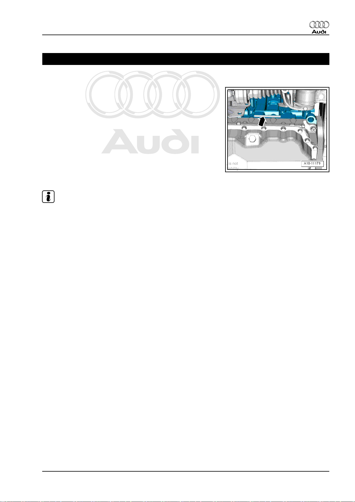
1 Engine number
♦ The engine number („Engine code“ and „Serial number“) can
be found on the rear of the joint between cylinder block and
sump (top section) -arrow-.
♦ There is also a sticker on the timing chain cover (top) showing
the „engine code“ and „serial number“.
♦ Starting with the letter „C“, the engine codes consist of 4 let‐
ters.
♦ The first 3 characters of the engine code stand for the engine
capacity and the mechanical construction and design. They
are stamped on the cylinder block, together with the serial
number.
♦ The 4th character indicates the power output and torque of the
engine, and is determined by the engine control unit.
Audi TT 2007 ➤
Note
♦
The 4-character engine code can be found on the type plate
(in versions for some countries only) and on the vehicle data
sticker and the engine control unit.
♦
Fitting locations of the type plate (certain countries only) and
the vehicle data sticker ⇒ Maintenance ; Booklet 810 .
1. Engine number 1
Page 8
Protected by copyright. Copying for private or commercial purposes, in part or in whole, is not
permitted unless authorised by AUDI AG. AUDI AG does not guarantee or accept any liability
with respect to the correctness of information in this document. Copyright by AUDI AG.
Audi TT 2007 ➤
5-cylinder direct petrol injection engine (2.5 ltr. 4-valve turbo), mechanics - Edition 12.2010
2 Engine data
Code letters CEPA
Capacity ltr. 2.480
Power output kW at rpm 250/5400 … 6500
Torque Nm at rpm 450/1600 … 5300
Bore ∅ in mm 82.5
Stroke mm 92.8
Compression ra‐
tio
RON at least
Injection/ignition system Bosch Motronic
Firing order
Exhaust gas recirculation no
Exhaust gas temperature control 1 senders
Turbocharging/supercharging Turbocharger
Knock control 2 sensors
Charge air cooling yes
Lambda control 1 probe before catalytic
Variable valve timing Inlet
Intake manifold change-over no
Secondary air system no
Valves per cylinder 4
1)
•
Unleaded premium RON 95 can also be used, but results
in reduced power
10
1)
98
1-2-4-5-3
converter
1 probe after catalytic con‐
verter
Exhaust
2 Rep. gr.00 - Technical data
Page 9
Protected by copyright. Copying for private or commercial purposes, in part or in whole, is not
permitted unless authorised by AUDI AG. AUDI AG does not guarantee or accept any liability
with respect to the correctness of information in this document. Copyright by AUDI AG.
5-cylinder direct petrol injection engine (2.5 ltr. 4-valve turbo), mechanics - Edition 12.2010
3 Safety precautions
Overview
♦ ⇒ „3.1 Working on the fuel system“, page 3
♦ ⇒ „3.2 Procedure before opening high-pressure section of in‐
jection system“, page 4
♦ ⇒ „3.3 Working on the cooling system“, page 4
♦ ⇒ „3.4 Working on vehicles with start/stop system“,
page 4
♦ ⇒ „3.5 Using testers and measuring instruments during a road
test“, page 5
♦ ⇒ „3.6 Working on the exhaust system“, page 5
3.1 Working on the fuel system
When working on the fuel system note the following warnings:
WARNING
Audi TT 2007 ➤
The fuel system operates at extremely high pressure. This can
cause injury.
♦ The fuel pressure in the high-pressure section of the in‐
jection system must be reduced to a residual pressure
prior to opening the system.
♦ Wrap a clean cloth around the connection and carefully
loosen the connection to allow the residual pressure to
dissipate.
– Procedure before opening high-pressure section of injection
system ⇒ Rep. gr. 24 .
Observe the following to prevent injuries to persons and damage
to the injection and ignition system:
♦ Always switch off the ignition before connecting or discon‐
necting electrical wiring for the injection or ignition system or
tester cables.
♦ Always switch off ignition before washing engine.
♦ Faults are stored in engine control unit(s) if electrical connec‐
tors were unplugged and engine was started: „Generate read‐
iness code“ in „Guided Functions“ ⇒ Vehicle diagnostic,
testing and information system VAS 5051.
Caution
To prevent irreparable damage to the electronic components
when disconnecting the battery:
♦ Observe notes on procedure for disconnecting the battery.
♦ Always switch off the ignition before disconnecting the
battery.
– Disconnect battery ⇒ Electrical system; Rep. gr. 27 .
3. Safety precautions 3
Page 10
Protected by copyright. Copying for private or commercial purposes, in part or in whole, is not
permitted unless authorised by AUDI AG. AUDI AG does not guarantee or accept any liability
with respect to the correctness of information in this document. Copyright by AUDI AG.
Audi TT 2007 ➤
5-cylinder direct petrol injection engine (2.5 ltr. 4-valve turbo), mechanics - Edition 12.2010
3.2 Procedure before opening high-pres‐
sure section of injection system
WARNING
The fuel system operates at extremely high pressure. This can
cause injury.
♦ The injection system consists of a high-pressure section
(maximum approx. 140 bar) and a low-pressure section
(approx. 6 bar).
♦ The fuel pressure in the high-pressure section must be
reduced to a residual pressure of approx. 6 bar prior to
opening the system. Procedure ⇒ Rep. gr. 24 .
3.3 Working on the cooling system
When working on the cooling system note the following warnings:
WARNING
Hot steam/hot coolant can escape - risk of scalding.
♦ The cooling system is under pressure when the engine is
hot.
♦ To allow pressure to dissipate, cover filler cap on coolant
expansion tank with cloth and open carefully.
3.4 Working on vehicles with start/stop sys‐
tem
When performing repairs on vehicles with start/stop system, note
the following:
WARNING
Risk of injury due to automatic engine start on vehicles with
start/stop system.
♦ On vehicles with activated start/stop system (this is indi‐
cated by a message in the instrument cluster display), the
engine may start automatically on demand.
♦ Therefore it is important to ensure that the start/stop sys‐
tem is deactivated when performing repairs (switch off
ignition, if required switch on ignition again).
4 Rep. gr.00 - Technical data
Page 11
Protected by copyright. Copying for private or commercial purposes, in part or in whole, is not
permitted unless authorised by AUDI AG. AUDI AG does not guarantee or accept any liability
with respect to the correctness of information in this document. Copyright by AUDI AG.
5-cylinder direct petrol injection engine (2.5 ltr. 4-valve turbo), mechanics - Edition 12.2010
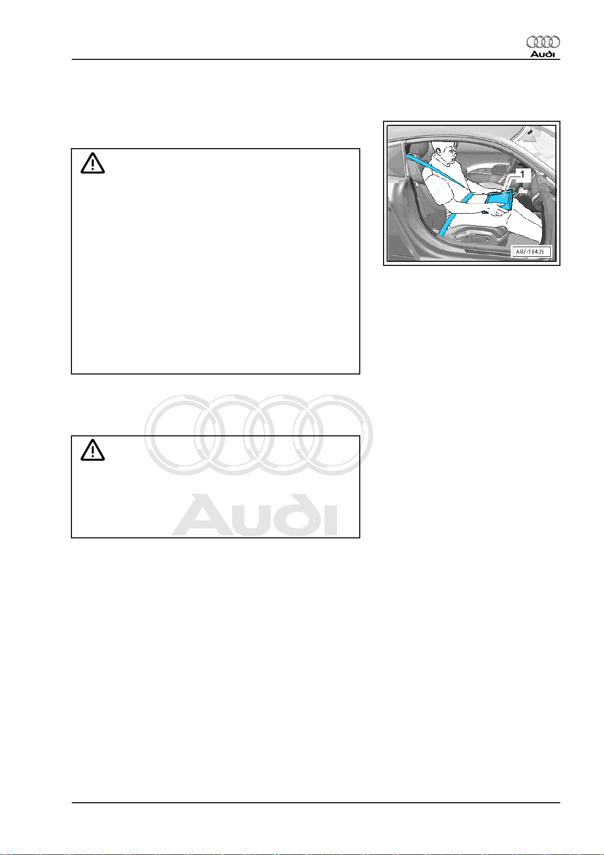
3.5 Using testers and measuring instru‐
ments during a road test
Note the following if testers and measuring instruments have to
be used during a road test:
WARNING
Accidents can be caused if the driver is distracted by test
equipment while road-testing, or if test equipment is not prop‐
erly secured.
Persons sitting in the front passenger's seat could be injured if
the airbag is triggered in an accident.
• The use of test equipment while driving causes distraction.
• There is an increased risk of injury if test equipment is not
secured.
♦ Move the passenger's seat back as far as it will go.
♦ Use only vehicle diagnosis and service information sys‐
tem -VAS 5052 A- or diagnosis system -VAS 5053- .
♦ The test equipment -1- must rest flat on the passenger's
thighs (as shown in illustration) and must be operated by
the passenger.
Audi TT 2007 ➤
3.6 Working on the exhaust system
When working on the exhaust system please note the following:
Caution
Avoid damage to flexible joint.
♦ Do not bend flexible joint more than 10°.
♦ Install flexible joint so that it is not under tension.
♦ Take care not to damage wire mesh on flexible joint.
3. Safety precautions 5
Page 12
Protected by copyright. Copying for private or commercial purposes, in part or in whole, is not
permitted unless authorised by AUDI AG. AUDI AG does not guarantee or accept any liability
with respect to the correctness of information in this document. Copyright by AUDI AG.
Audi TT 2007 ➤
5-cylinder direct petrol injection engine (2.5 ltr. 4-valve turbo), mechanics - Edition 12.2010
4 General repair instructions
Overview
♦ ⇒ „4.1 Rules for cleanliness when working on fuel supply sys‐
tem, injection system and turbocharger“, page 6
♦ ⇒ „4.2 Checking fuel system for leaks“, page 6
♦ ⇒ „4.3 Foreign particles in engine“, page 6
♦ ⇒ „4.4 Contact corrosion!“, page 7
♦ ⇒ „4.5 Routing and attachment of pipes, hoses and wiring“,
page 7
♦ ⇒ „4.6 Checking vacuum system“, page 7
♦ ⇒ „4.7 Installing radiators, condensers and charge air coolers“,
page 8
4.1 Rules for cleanliness when working on fuel supply system, injection system and turbocharger
Even small amounts of dirt can cause malfunctions. For this rea‐
son, please observe the following rules when working on the fuel
supply system, injection system and turbocharger:
♦ Carefully clean connection points and the surrounding area
with engine cleaner or brake cleaner and dry thoroughly before
opening.
♦ Seal off open pipes/lines and connections immediately with
clean plugs, e.g. from engine bung set -VAS 6122- .
♦ Place parts that have been removed on a clean surface and
cover them over. Use only lint-free cloths.
♦ Carefully cover or seal open components if repairs cannot be
carried out immediately.
♦ Only install clean components; replacement parts should only
be unpacked immediately prior to installation. Do not use parts
that have not been stored in their packing (e.g. in tool boxes
etc.).
♦ When the system is open, do not work with compressed air
and do not move the vehicle.
♦ Protect unplugged electrical connectors against dirt and mois‐
ture and make sure connections are dry when attaching.
4.2 Checking fuel system for leaks
– Allow engine to run for several minutes at moderate rpm.
– Switch off ignition.
– Check complete fuel system for leaks.
– If leaks are found although the connections have been tight‐
ened to the correct torque, the relevant component must be
renewed.
– Road-test vehicle and accelerate with full throttle at least once.
– Then inspect high-pressure section of fuel system again for
leaks.
4.3 Foreign particles in engine
♦ When performing assembly work on the engine, all open pas‐
sages in the intake and exhaust systems must be sealed with
6 Rep. gr.00 - Technical data
Page 13

Protected by copyright. Copying for private or commercial purposes, in part or in whole, is not
permitted unless authorised by AUDI AG. AUDI AG does not guarantee or accept any liability
with respect to the correctness of information in this document. Copyright by AUDI AG.
5-cylinder direct petrol injection engine (2.5 ltr. 4-valve turbo), mechanics - Edition 12.2010
suitable plugs (e.g. from engine bung set -VAS 6122- ) to pre‐
vent foreign particles from entering the engine.
4.4 Contact corrosion!
Contact corrosion can occur if unsuitable fasteners are used (e.g.
bolts, nuts, washers, etc.).
For this reason, only fasteners with a special surface coating are
used.
Additionally, all rubber and plastic parts and all adhesives are
made of non-conductive materials.
Always install new parts if you are not sure whether used parts
can be re-fitted ⇒ Electronic parts catalogue .
Note the following:
♦ We recommend using only genuine replacement parts; these
have been tested and are compatible with aluminium.
♦ We recommend the use of Audi accessories.
♦ Damage caused by contact corrosion is not covered under
warranty.
Audi TT 2007 ➤
4.5 Routing and attachment of pipes, hoses and wiring
♦ Mark fuel lines, hydraulic lines, vacuum lines, lines for activa‐
ted charcoal filter system and electrical wiring etc. before
removal so they can be re-installed in the original positions
and correctly connected. Make sketches or take photographs
if necessary.
♦ To prevent damaging pipes, hoses and wiring, ensure suffi‐
cient clearance from all moving or hot components in engine
compartment (little space in engine compartment).
4.6 Checking vacuum system
Special tools and workshop equipment required
♦ Hand vacuum pump -VAS 6213-
Procedure
– Check all vacuum lines in the complete vacuum system for:
♦ Cracks
♦ Traces of animal bites
♦ Kinked or crushed lines
♦ Lines porous or leaking
– Check vacuum line to solenoid valve and from solenoid valve
to corresponding component.
4. General repair instructions 7
Page 14
Protected by copyright. Copying for private or commercial purposes, in part or in whole, is not
permitted unless authorised by AUDI AG. AUDI AG does not guarantee or accept any liability
with respect to the correctness of information in this document. Copyright by AUDI AG.
Audi TT 2007 ➤
5-cylinder direct petrol injection engine (2.5 ltr. 4-valve turbo), mechanics - Edition 12.2010
– If a fault is stored in the memory, check the vacuum lines lead‐
ing to the corresponding component and also check the re‐
maining vacuum lines in the system.
– If it is not possible to build up a vacuum with the hand vacuum
pump -VAS 6213- or if the vacuum pressure drops again im‐
mediately, check the hand vacuum pump and connecting
hoses for leaks.
4.7 Installing radiators, condensers and charge air coolers
Even when the radiator, condenser and charge air cooler are cor‐
rectly installed, slight impressions may be visible on the fins of
these components. This does not mean that the components are
damaged. If the fins are only very slightly distorted, this does not
justify renewal of the radiator, condenser or charge air cooler.
8 Rep. gr.00 - Technical data
Page 15
Protected by copyright. Copying for private or commercial purposes, in part or in whole, is not
permitted unless authorised by AUDI AG. AUDI AG does not guarantee or accept any liability
with respect to the correctness of information in this document. Copyright by AUDI AG.
5-cylinder direct petrol injection engine (2.5 ltr. 4-valve turbo), mechanics - Edition 12.2010
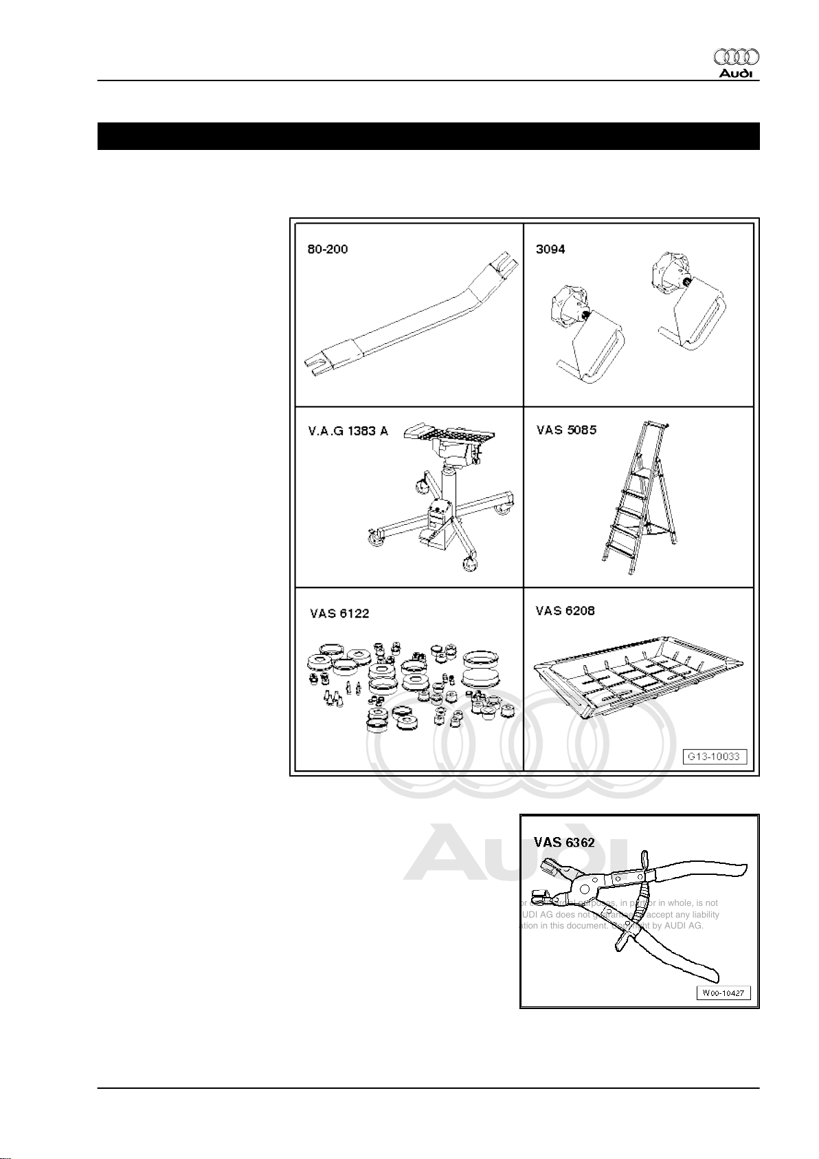
10 – Removing and installing engine
1 Removing engine
Special tools and workshop
equipment required
♦ Removal lever -80 - 200-
♦ Hose clamps for hoses up
to 25 mm -3094-
♦ Engine and gearbox jack -
V.A.G 1383 A-
♦ Stepladder -VAS 5085-
♦ Engine bung set -VAS
6122-
♦ Drip tray for workshop hoist
-VAS 6208-
Audi TT 2007 ➤
♦ Hose clip pliers -VAS 6362-
1. Removing engine 9
Page 16
Protected by copyright. Copying for private or commercial purposes, in part or in whole, is not
permitted unless authorised by AUDI AG. AUDI AG does not guarantee or accept any liability
with respect to the correctness of information in this document. Copyright by AUDI AG.
Audi TT 2007 ➤
5-cylinder direct petrol injection engine (2.5 ltr. 4-valve turbo), mechanics - Edition 12.2010
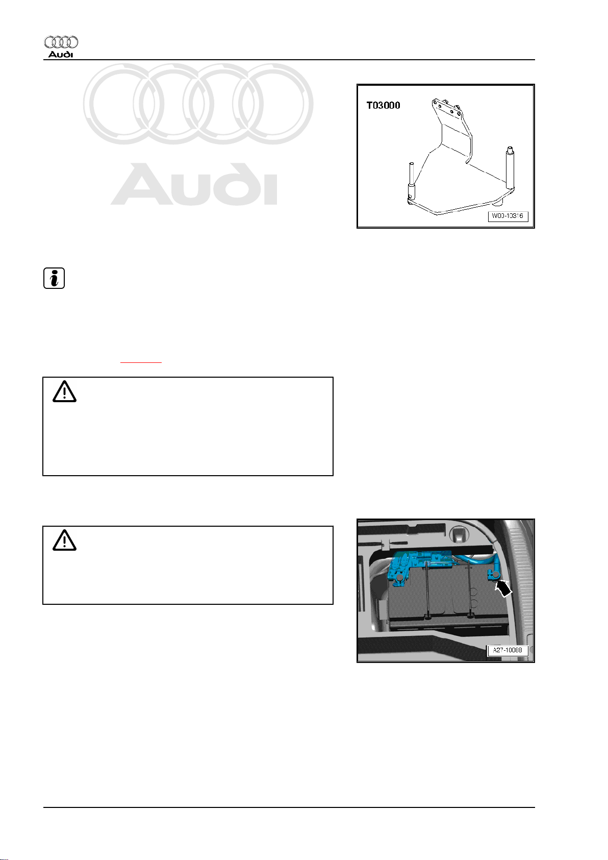
♦ Engine bracket -T03000-
Procedure
Note
♦
The engine is removed from underneath together with the
gearbox.
♦
Fit cable ties in the original positions when installing.
♦
Routing and attachment of pipes, hoses and wiring in engine
compartment ⇒ page 7 .
WARNING
The fuel system operates at extremely high pressure. This can
cause injury.
♦ The fuel pressure in the high-pressure section of the in‐
jection system must be reduced to a residual pressure
prior to opening the system.
– Reduce fuel pressure in high-pressure section of injection sys‐
tem ⇒ Rep. gr. 24 .
Caution
To prevent irreparable damage to the electronic components
when disconnecting the battery:
♦ Observe notes on procedure for disconnecting the battery.
– With ignition switched off, disconnect earth cable -arrow- at
battery ⇒ Electrical system; Rep. gr. 27 .
10 Rep. gr.10 - Removing and installing engine
Page 17
Protected by copyright. Copying for private or commercial purposes, in part or in whole, is not
permitted unless authorised by AUDI AG. AUDI AG does not guarantee or accept any liability
with respect to the correctness of information in this document. Copyright by AUDI AG.
5-cylinder direct petrol injection engine (2.5 ltr. 4-valve turbo), mechanics - Edition 12.2010
WARNING
Hot steam/hot coolant can escape - risk of scalding.
♦ The cooling system is under pressure when the engine is
hot.
♦ Cover filler cap on coolant expansion tank with a cloth and
open carefully to dissipate pressure.
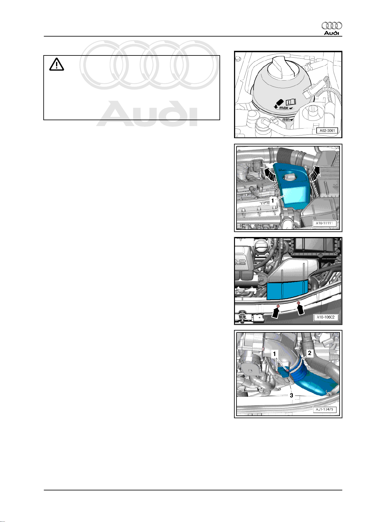
– Open filler cap on coolant expansion tank.
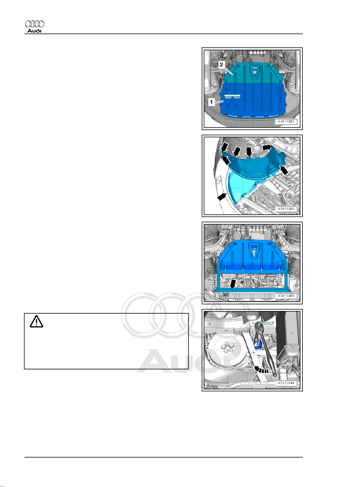
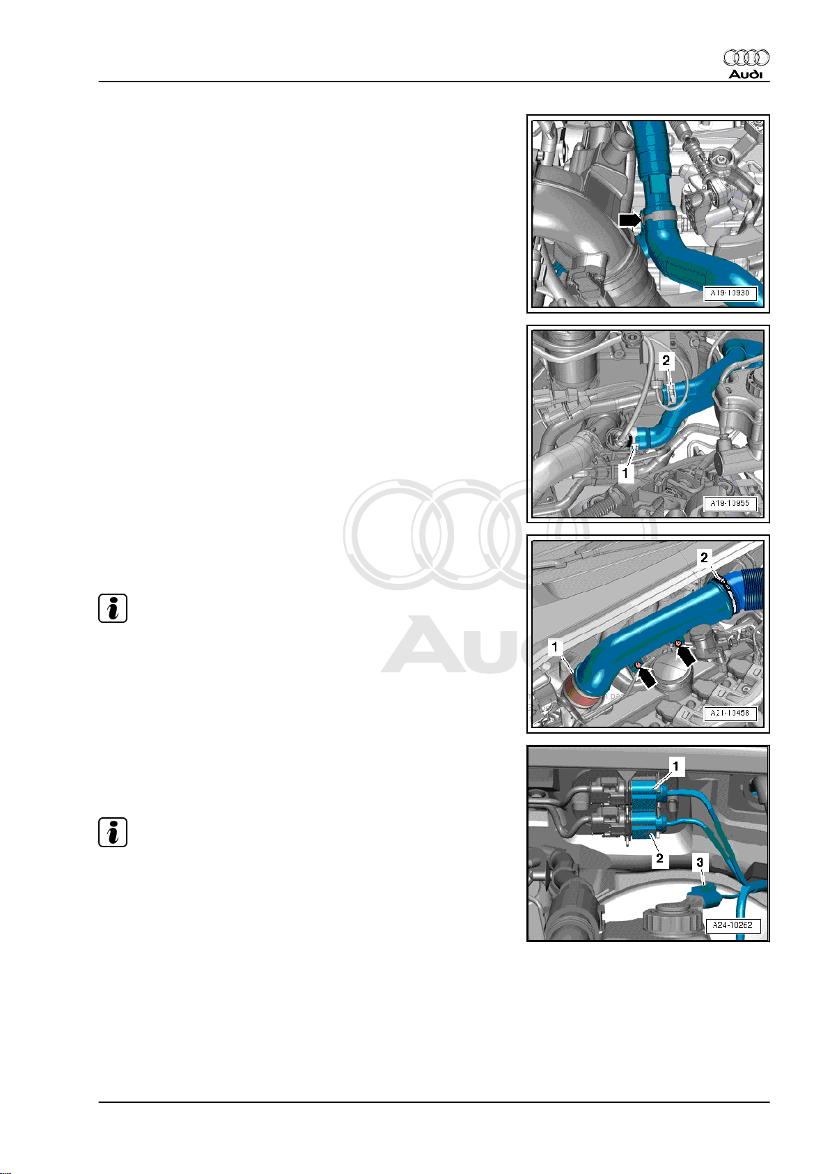
– Lift off engine cover panel -1- -arrows-.
Audi TT 2007 ➤
– Unscrew bolts -arrows- and remove air duct.
– Unplug electrical connector -3-.
– Unscrew bolts -1- and remove charge pressure sender -G31- /
intake air temperature sender 2 -G299- .
– Loosen hose clip -2-.
1. Removing engine 11
Page 18
Protected by copyright. Copying for private or commercial purposes, in part or in whole, is not
permitted unless authorised by AUDI AG. AUDI AG does not guarantee or accept any liability
with respect to the correctness of information in this document. Copyright by AUDI AG.
Audi TT 2007 ➤
5-cylinder direct petrol injection engine (2.5 ltr. 4-valve turbo), mechanics - Edition 12.2010
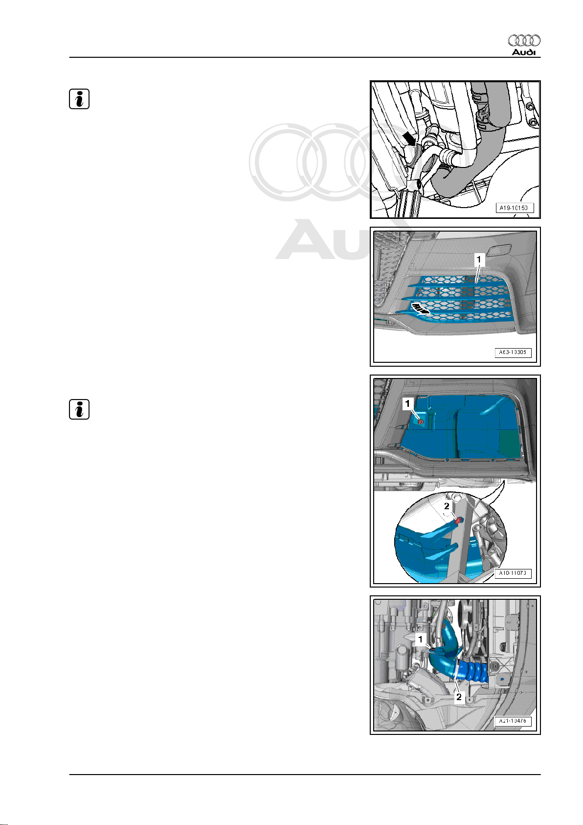
– Remove front wheels ⇒ Wheels and tyres; Rep. gr. 44 .
– Remove front noise insulation -1- ⇒ Rep. gr. 66 .
– Remove front bottom sections of wheel housing liners (left and
right)⇒ Rep. gr. 66 .
– Remove noise insulation frame -arrow- together with rear
noise insulation ⇒ Rep. gr. 50 .
Caution
If a used belt runs in the opposite direction when it is refitted,
this can cause breakage.
♦ Before removing, mark direction of rotation of poly V-belt
for air conditioner compressor with chalk or felt-tipped pen
for re-installation.
– To slacken poly V-belt turn tensioner in clockwise direction
-arrow-.
– Detach poly V-belt for air conditioner compressor and release
tensioner.
12 Rep. gr.10 - Removing and installing engine
Page 19
Protected by copyright. Copying for private or commercial purposes, in part or in whole, is not
permitted unless authorised by AUDI AG. AUDI AG does not guarantee or accept any liability
with respect to the correctness of information in this document. Copyright by AUDI AG.
5-cylinder direct petrol injection engine (2.5 ltr. 4-valve turbo), mechanics - Edition 12.2010
Note
Collect drained coolant in a clean container for re-use or disposal.
– Place drip tray for workshop hoist -VAS 6208- under connec‐
tion.
– Lift retaining clip -arrow-, disconnect coolant hose (bottom)
from radiator and drain off coolant.
Vehicles with manual gearbox:
– Detach air intake grille -1- from bumper cover -arrow-.
Audi TT 2007 ➤
– Unscrew bolt -1- and remove air duct.
Note
Disregard -item 2-.
– Remove bolt -1-.
– Release hose clip -2- and detach air pipe.
1. Removing engine 13
Page 20
Protected by copyright. Copying for private or commercial purposes, in part or in whole, is not
permitted unless authorised by AUDI AG. AUDI AG does not guarantee or accept any liability
with respect to the correctness of information in this document. Copyright by AUDI AG.
Audi TT 2007 ➤
5-cylinder direct petrol injection engine (2.5 ltr. 4-valve turbo), mechanics - Edition 12.2010
Vehicles with dual clutch gearbox:
– Place drip tray for workshop hoist -VAS 6208- under connec‐
tion.
– Release hose clip -arrow-, disconnect coolant hose and drain
off coolant.
– Remove nuts -arrows-.
– Release hose clip -1- and detach air pipe.
All vehicles (continued):
– Place drip tray for workshop hoist -VAS 6208- under connec‐
tion.
– Release hose clips, disconnect coolant hoses -1- and -2- and
drain off coolant.
Note
Disregard -item 3-.
– Unplug electrical connector -2- for radiator fan.
– Remove bolts -3-.
WARNING
Risk of injury caused by fuel.
♦ To allow the fuel pressure to dissipate, wrap a clean cloth
around the connection and carefully loosen the connec‐
tion before opening the fuel system.
Caution
Risk of damage caused by particles of dirt.
♦ Observe rules for cleanliness when working on the fuel
supply system ⇒ page 6 .
14 Rep. gr.10 - Removing and installing engine
Page 21
Protected by copyright. Copying for private or commercial purposes, in part or in whole, is not
permitted unless authorised by AUDI AG. AUDI AG does not guarantee or accept any liability
with respect to the correctness of information in this document. Copyright by AUDI AG.
5-cylinder direct petrol injection engine (2.5 ltr. 4-valve turbo), mechanics - Edition 12.2010
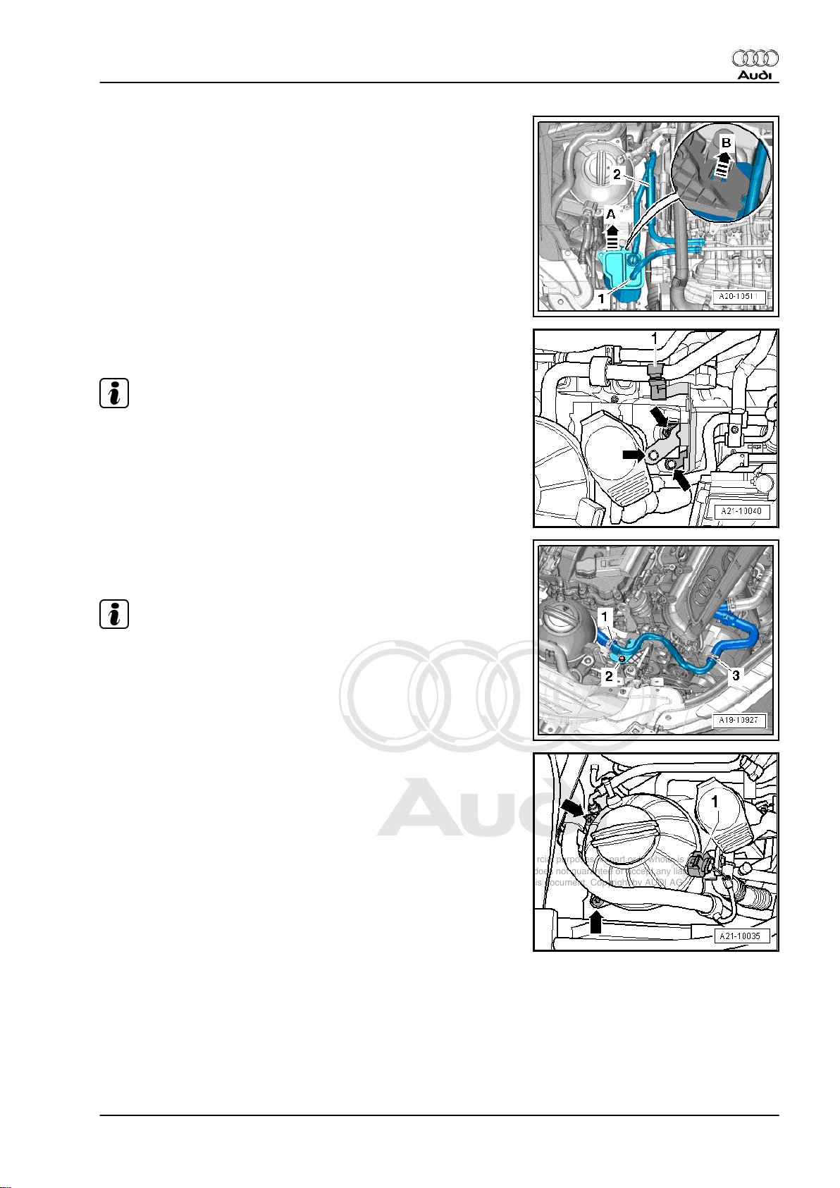
– Disengage fuel supply line from retainer and remove heat in‐
sulation sleeve -2- at fuel supply line connection.
– Disconnect fuel supply pipe (pull release ring).
– Seal off open pipes/lines and connections with clean plugs
from engine bung set -VAS 6122- .
– Disconnect hose -1- from activated charcoal filter.
– Release activated charcoal filter -arrow B-, lift off -arrow A- and
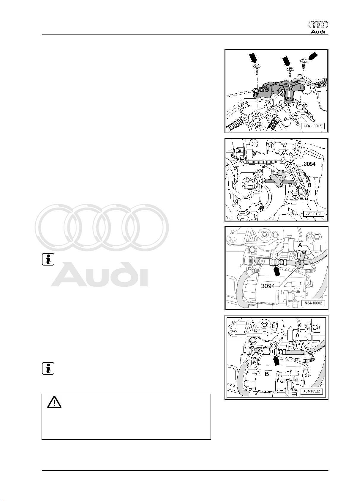
move clear to one side.
– Remove bolts -arrows- and detach bracket for activated char‐
coal filter.
Note
Disregard -item 1-.
Audi TT 2007 ➤
– Release hose clip -3- and detach coolant hose.
– Guide coolant hose downwards and drain off coolant.
Note
Disregard -items 1, 2-.
– Unplug electrical connector -1- for coolant shortage indicator
switch -F66- .
– Remove bolts -arrows- and move coolant expansion tank with
coolant pipe (right-side) to side.
1. Removing engine 15
Page 22
Protected by copyright. Copying for private or commercial purposes, in part or in whole, is not
permitted unless authorised by AUDI AG. AUDI AG does not guarantee or accept any liability
with respect to the correctness of information in this document. Copyright by AUDI AG.
Audi TT 2007 ➤
5-cylinder direct petrol injection engine (2.5 ltr. 4-valve turbo), mechanics - Edition 12.2010
Caution
If a used belt runs in the opposite direction when it is refitted,
this can cause breakage.
♦ Before removing, mark direction of rotation of poly V-belt
for alternator and coolant pump with chalk or felt-tipped
pen for re-installation.
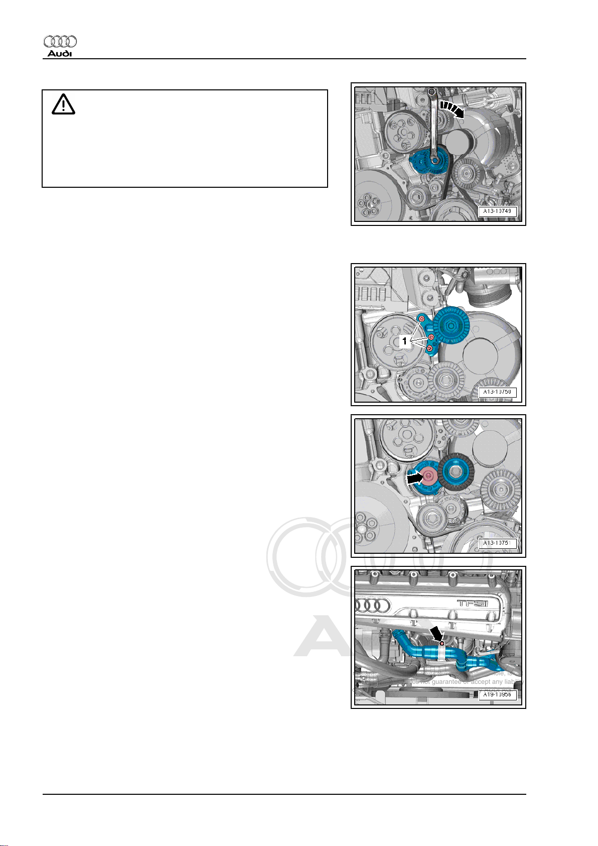
– To slacken poly V-belt turn tensioner in clockwise direction
-arrow-.
– Detach poly V-belt for alternator and coolant pump and re‐
lease tensioner.
– Unscrew bolts -1- and remove idler roller.
– Remove bolt -arrow- and take off tensioner.
– Remove bolt -arrow- from retaining clamp.
16 Rep. gr.10 - Removing and installing engine
Page 23
Protected by copyright. Copying for private or commercial purposes, in part or in whole, is not
permitted unless authorised by AUDI AG. AUDI AG does not guarantee or accept any liability
with respect to the correctness of information in this document. Copyright by AUDI AG.
5-cylinder direct petrol injection engine (2.5 ltr. 4-valve turbo), mechanics - Edition 12.2010
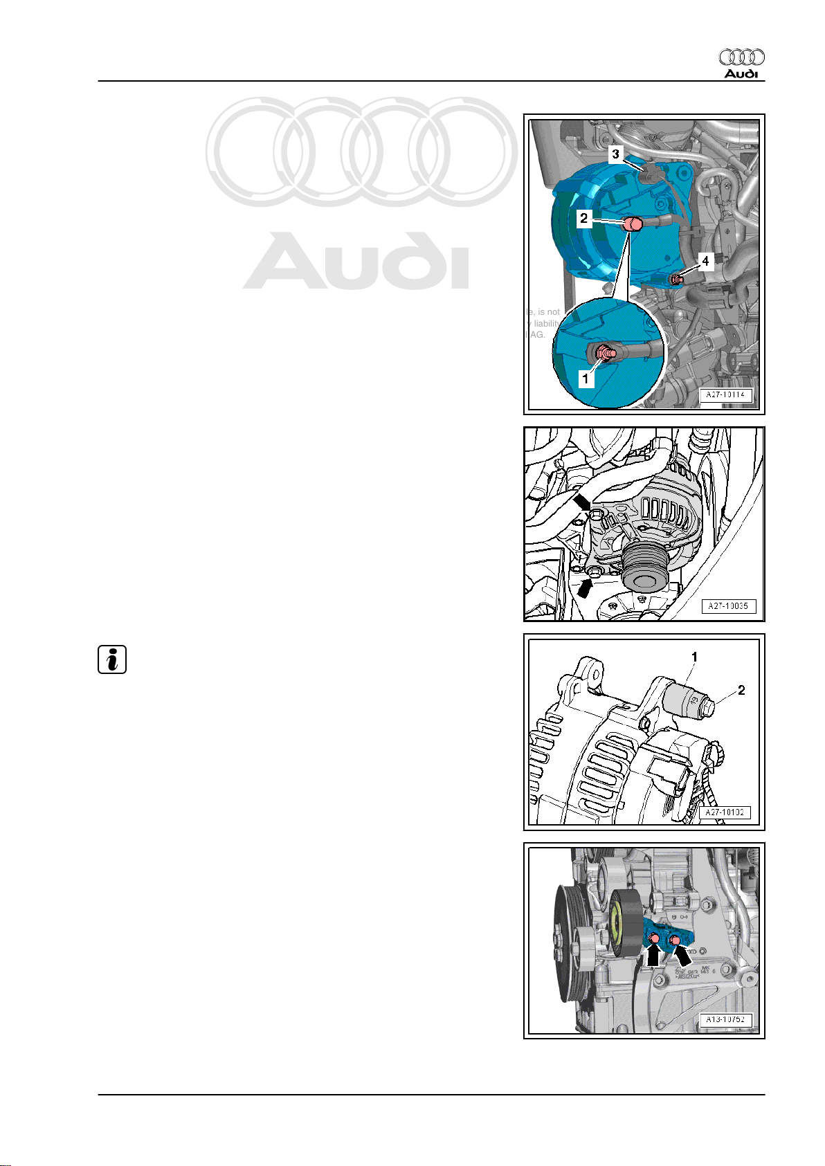
– Unplug electrical connector -3- at alternator.
– Lever off protective cap -2- and remove nut -1- for terminal 30/
B+.
– Remove nut -4- and detach wiring clamp.
– Remove bolts -arrows- and lift out alternator.
Audi TT 2007 ➤
Note
♦
Apply 1/2” socket insert AF 19 -item 1- to sliding bush if alter‐
nator is stuck in bracket.
♦
Screw a bolt M8x45 -item 2- into sliding bush and pull sliding
bush out of alternator by screwing in bolt.
– Unscrew bolts -arrows- and remove idler roller.
1. Removing engine 17
Page 24
Protected by copyright. Copying for private or commercial purposes, in part or in whole, is not
permitted unless authorised by AUDI AG. AUDI AG does not guarantee or accept any liability
with respect to the correctness of information in this document. Copyright by AUDI AG.
Audi TT 2007 ➤
5-cylinder direct petrol injection engine (2.5 ltr. 4-valve turbo), mechanics - Edition 12.2010
– Release hose clip -2- and detach coolant hose.
Note
Disregard -item 1-.
– Move clear coolant line -1- -arrows- and move to rear.
– Remove bolts -1- and lift out radiator cowl.
– Release hose clips -2- and -3- and disconnect air hoses.
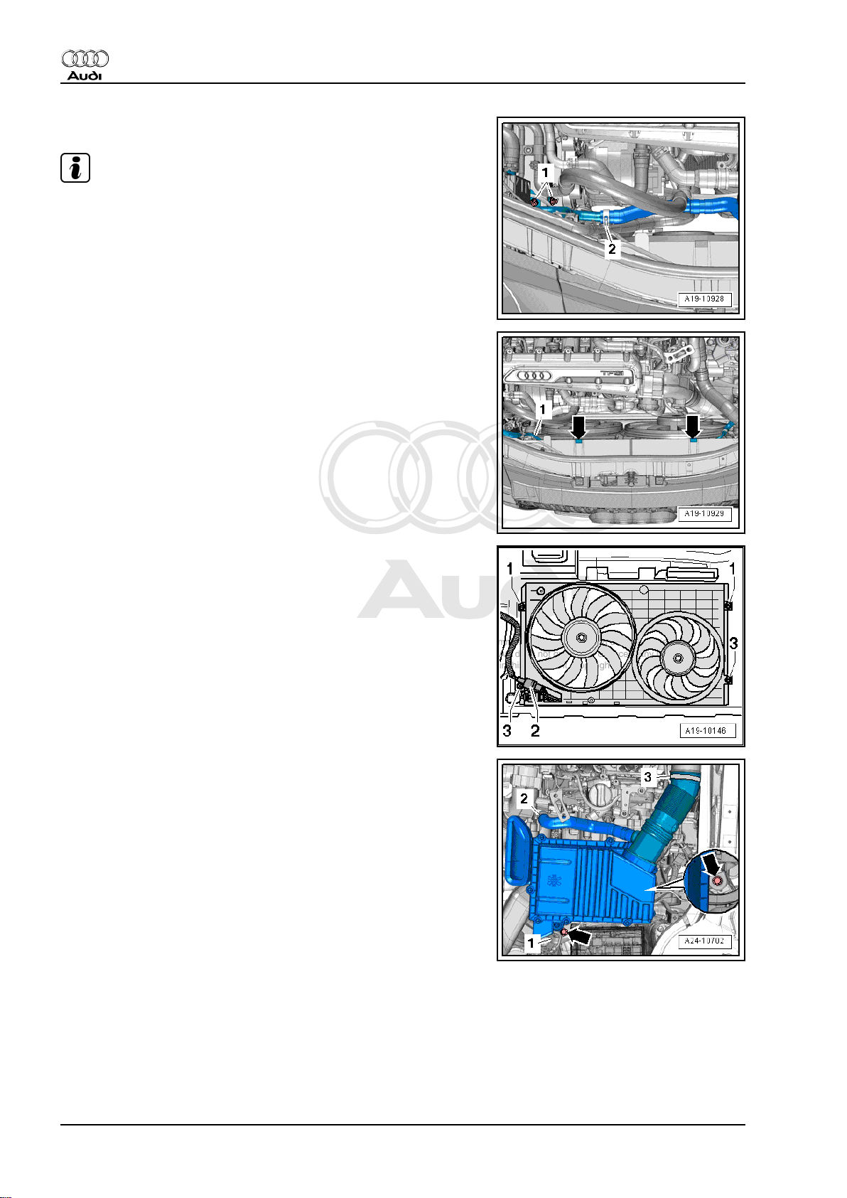
– Move clear electrical wiring harness -1- at bracket for air clean‐
er housing.
– Unscrew bolts -arrows- and detach air cleaner housing.
18 Rep. gr.10 - Removing and installing engine
Page 25
Protected by copyright. Copying for private or commercial purposes, in part or in whole, is not
permitted unless authorised by AUDI AG. AUDI AG does not guarantee or accept any liability
with respect to the correctness of information in this document. Copyright by AUDI AG.
5-cylinder direct petrol injection engine (2.5 ltr. 4-valve turbo), mechanics - Edition 12.2010
– Release hose clip -arrow- and detach coolant hose.
– Release hose clips -1- and -2- and detach coolant hoses.
Audi TT 2007 ➤
– Remove bolts -arrows-.
– Release hose clip -1- and detach air pipe.
Note
Disregard -item 2-.
– Remove electrical connector -1- for Lambda probe -G39- from
bracket and unplug connector.
– Move clear electrical wiring to Lambda probe.
Note
Disregard -items 2, 3-.
1. Removing engine 19
Page 26
Protected by copyright. Copying for private or commercial purposes, in part or in whole, is not
permitted unless authorised by AUDI AG. AUDI AG does not guarantee or accept any liability
with respect to the correctness of information in this document. Copyright by AUDI AG.
Audi TT 2007 ➤
5-cylinder direct petrol injection engine (2.5 ltr. 4-valve turbo), mechanics - Edition 12.2010
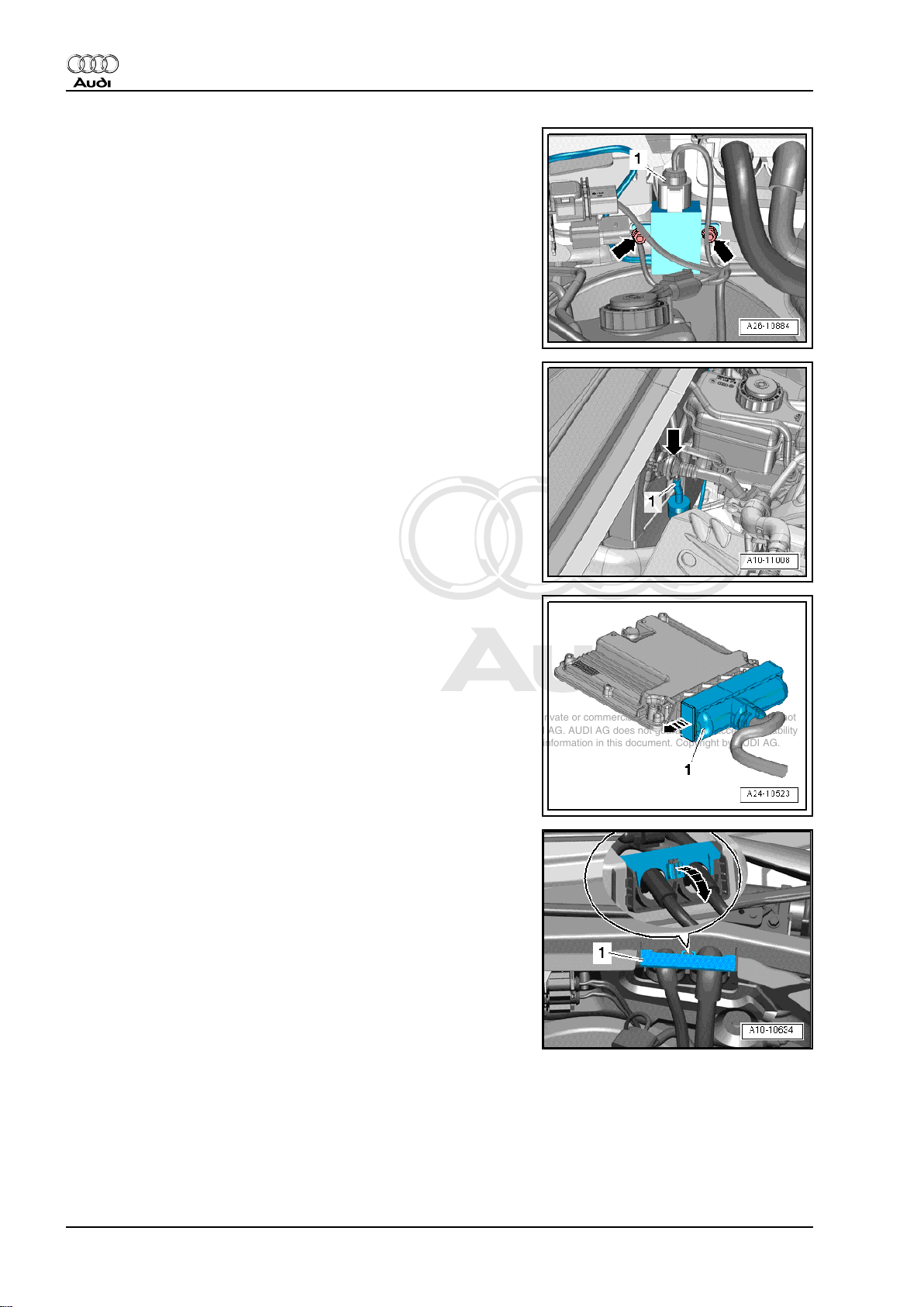
– Unplug electrical connector -1-.
– Remove bolts -arrows- and place exhaust gas temperature
sender 1 -G235- onto cylinder head.
– Detach vacuum hose -1- from non-return valve -arrow-.
– Pull non-return valve off brake servo.
– Release electrical connector -1- for engine wiring harness
-arrow- and detach ⇒ Removing and installing engine control
unit -J623-; Rep. gr. 24 .
– Release wiring protector -1- for engine wiring harness
-arrow- and lift off.
20 Rep. gr.10 - Removing and installing engine
Page 27
Protected by copyright. Copying for private or commercial purposes, in part or in whole, is not
permitted unless authorised by AUDI AG. AUDI AG does not guarantee or accept any liability
with respect to the correctness of information in this document. Copyright by AUDI AG.
5-cylinder direct petrol injection engine (2.5 ltr. 4-valve turbo), mechanics - Edition 12.2010
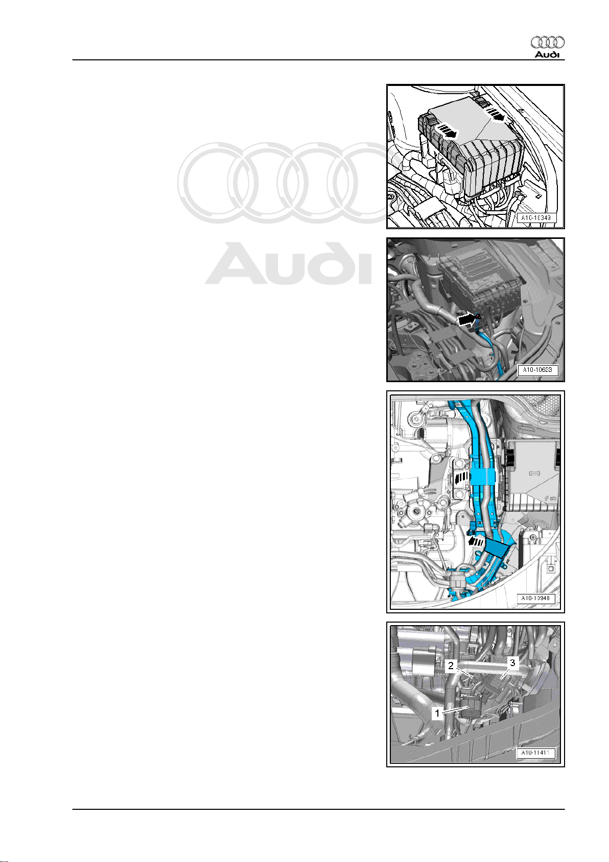
– Slide the two clips in the direction of the -arrows- and remove
cover from electronics box in engine compartment.
– Remove nut -arrow-, detach terminal 30 wire from electronics
box in engine compartment and move it clear.
Audi TT 2007 ➤
– Open wiring duct brackets -arrows-.
– Unclip electrical connectors -2- and -3- from bracket and un‐
plug connectors.
– Unclip electrical connector -1- from bracket and unplug.
– Open wiring duct bracket located underneath.
– Unclip wiring harness for engine control unit from wiring duct.
– Place engine wiring harness on top of engine.
– Secure engine control unit to prevent it falling.
1. Removing engine 21
Page 28
Protected by copyright. Copying for private or commercial purposes, in part or in whole, is not
permitted unless authorised by AUDI AG. AUDI AG does not guarantee or accept any liability
with respect to the correctness of information in this document. Copyright by AUDI AG.
Audi TT 2007 ➤
5-cylinder direct petrol injection engine (2.5 ltr. 4-valve turbo), mechanics - Edition 12.2010
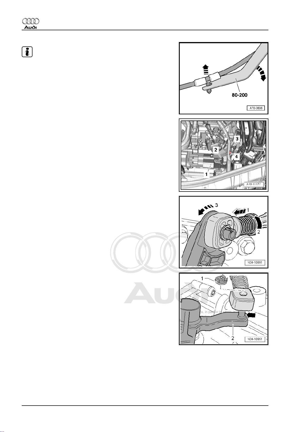
Note
Use removal lever -80 - 200- to lever out the wiring clips.
Vehicles with manual gearbox:
– Unplug electrical connector -2- at starter.
– Push back protective cover -1- and unscrew B+ cable at starter
solenoid switch.
– Remove bolt -4- for earth connection.
– Unplug electrical connector -3- for reversing light switch -F4- .
– Pull locking device forwards onto stop -arrow 1- and lock by
turning anti-clockwise -arrow 2-.
– Press relay lever towards front -arrow 3-, take gate selector
cable out of end-piece.
– Detach securing clip -1- for gear selector cable from gearbox
selector lever -2- and pull cable off pin -arrow-.
22 Rep. gr.10 - Removing and installing engine
Page 29
Protected by copyright. Copying for private or commercial purposes, in part or in whole, is not
permitted unless authorised by AUDI AG. AUDI AG does not guarantee or accept any liability
with respect to the correctness of information in this document. Copyright by AUDI AG.
5-cylinder direct petrol injection engine (2.5 ltr. 4-valve turbo), mechanics - Edition 12.2010
– Remove bolts -arrows-, detach cable support bracket from
gearbox and tie up to the left side.
– If a plastic pipe is installed between clutch master cylinder and
slave cylinder, clamp off supply hose to clutch master cylinder
using hose clamps for hoses up to 25 mm -3094- .
Audi TT 2007 ➤
– If a pipe/hose assembly is installed between clutch master
cylinder and slave cylinder, clamp off hose -A- using hose
clamps for hoses up to 25 mm -3094- .
Note
♦
Disregard -arrow-.
♦
Make sure brake fluid does not come into contact with starter
or gearbox when performing the following operations. If it
does, clean affected area thoroughly.
– Pull out clip -arrow- as far as stop.
– Pull plastic pipe or pipe/hose assembly -A- out of bleeder con‐
nection for clutch slave cylinder.
– Seal off open pipes/lines and connections with clean plugs
from engine bung set -VAS 6122- .
Note
Disregard -item B-.
Caution
Risk of contamination by escaping brake fluid.
♦ Do not operate clutch pedal after detaching pipe from
bleeder connection on clutch slave cylinder.
1. Removing engine 23
Page 30
Protected by copyright. Copying for private or commercial purposes, in part or in whole, is not
permitted unless authorised by AUDI AG. AUDI AG does not guarantee or accept any liability
with respect to the correctness of information in this document. Copyright by AUDI AG.
Audi TT 2007 ➤
5-cylinder direct petrol injection engine (2.5 ltr. 4-valve turbo), mechanics - Edition 12.2010
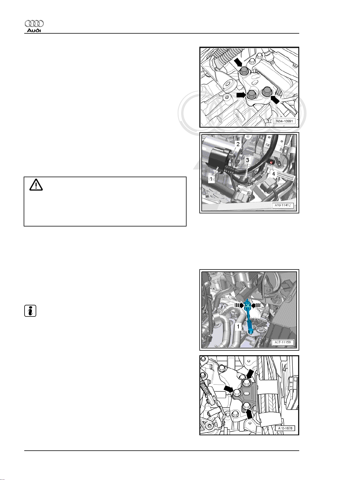
– Loosen bolts -arrows- for gearbox mounting approx. 2 turns.
Vehicles with dual clutch gearbox:
– Unplug electrical connector -2- at starter.
– Push back protective cover -1- and unscrew B+ cable at starter
solenoid switch.
– Remove bolt -4- for earth connection.
Caution
Risk of irreparable damage to gearbox control unit (mecha‐
tronic unit) because of static discharge.
♦ Do NOT touch connector contacts in gearbox connector
with your hands.
– Touch gearbox housing with your hand (without wearing
gloves) to eliminate static charge.
– Turn retainer catch anti-clockwise and unplug electrical con‐
nector -3- at gearbox.
– Pry ball socket of selector lever cable off gearbox selector lev‐
er using removal lever -80 - 200- .
– Release fasteners -arrows- and move selector lever cable
clear.
Note
Take care not to bend or kink selector lever cable.
– Loosen bolts -arrows- for gearbox mounting approx. 2 turns.
24 Rep. gr.10 - Removing and installing engine
Page 31

Protected by copyright. Copying for private or commercial purposes, in part or in whole, is not
permitted unless authorised by AUDI AG. AUDI AG does not guarantee or accept any liability
with respect to the correctness of information in this document. Copyright by AUDI AG.
5-cylinder direct petrol injection engine (2.5 ltr. 4-valve turbo), mechanics - Edition 12.2010
All vehicles (continued):
– Loosen bolt -3- and push clamp onto starter catalytic convert‐
er.
– Remove bolt -2-, tie up starter catalytic converter to rear.
Note
Disregard -item 1-.
– Remove bolts -1- and -2-.
– Release hose clips -arrows- and remove air pipe.
Audi TT 2007 ➤
– Unplug electrical connector -1- on air conditioner compressor
regulating valve -N280- .
Caution
Danger of damage to refrigerant lines and hoses.
♦ Do NOT stretch, kink or bend refrigerant lines and hoses.
– Remove bolts -arrows-.
– Detach air conditioner compressor from bracket for ancillaries
and tie up to the right side.
– Remove nuts -1- and detach heat shield for drive shaft (right-
side).
– Remove drive shaft (left and right) ⇒ Rep. gr. 40 .
1. Removing engine 25
Page 32

Protected by copyright. Copying for private or commercial purposes, in part or in whole, is not
permitted unless authorised by AUDI AG. AUDI AG does not guarantee or accept any liability
with respect to the correctness of information in this document. Copyright by AUDI AG.
Audi TT 2007 ➤
5-cylinder direct petrol injection engine (2.5 ltr. 4-valve turbo), mechanics - Edition 12.2010
– Remove bolts -1, 2, 3- and detach pendulum support.
– Unplug electrical connector -1- at oil level and oil temperature
sender -G266- .
– Unclip bracket -2- for electrical wiring from subframe.
– Remove nuts -1- and -2-.
– Loosen clamps -1- and -2- and move to front.
– Detach catalytic converter (left and right).
26 Rep. gr.10 - Removing and installing engine
Page 33

Protected by copyright. Copying for private or commercial purposes, in part or in whole, is not
permitted unless authorised by AUDI AG. AUDI AG does not guarantee or accept any liability
with respect to the correctness of information in this document. Copyright by AUDI AG.
5-cylinder direct petrol injection engine (2.5 ltr. 4-valve turbo), mechanics - Edition 12.2010
– Mark position of flexible coupling and flange for bevel box in
relation to each other for re-installation.
– Remove bolts -arrows- for flexible coupling for propshaft at
bevel box (select gear on gearbox).
Caution
Make sure not to damage the oil seal -arrow- in the propshaft
flange.
♦ Push the propshaft horizontally to the rear as far as pos‐
sible.
Audi TT 2007 ➤
Note
The propshaft must be renewed if oil seal is damaged.
– Unscrew pin -T03000/1- from engine bracket -T03000- .
– Fit engine bracket -T03000- with remaining pin -3- to cylinder
block, screw in bolts -1- and -2- by hand until they make con‐
tact.
– Fit pin -T03000/1- to cylinder block and tighten to 20 Nm.
– Tighten bolts -1- and -2- to 25 Nm.
– Insert engine and gearbox jack -V.A.G 1383 A- in engine
bracket -T03000- and raise engine/gearbox assembly slightly.
1. Removing engine 27
Page 34

Protected by copyright. Copying for private or commercial purposes, in part or in whole, is not
permitted unless authorised by AUDI AG. AUDI AG does not guarantee or accept any liability
with respect to the correctness of information in this document. Copyright by AUDI AG.
Audi TT 2007 ➤
5-cylinder direct petrol injection engine (2.5 ltr. 4-valve turbo), mechanics - Edition 12.2010
Note
To unscrew bolts for assembly mounting use stepladder VAS 5085- .
– Remove bolts -1- and -arrows- for engine mounting (left-side).
Note
The bolt at the rear of the cylinder block can be accessed from
the wheel housing side.
– Remove bolts -arrows- securing gearbox mounting.
Caution
Danger of damage to hoses, pipes and wiring connections and
to engine compartment.
♦ Check that all hoses and wiring connections between en‐
gine, gearbox, subframe and body have been detached.
♦ Carefully guide engine/gearbox assembly out of engine
compartment when lowering.
♦ Make sure there is sufficient clearance from air conditioner
compressor.
– Swing gearbox section of engine/gearbox assembly to front
and only then lower further.
28 Rep. gr.10 - Removing and installing engine
Page 35

Protected by copyright. Copying for private or commercial purposes, in part or in whole, is not
permitted unless authorised by AUDI AG. AUDI AG does not guarantee or accept any liability
with respect to the correctness of information in this document. Copyright by AUDI AG.
5-cylinder direct petrol injection engine (2.5 ltr. 4-valve turbo), mechanics - Edition 12.2010
2 Separating engine from manual gear‐
box
Special tools and workshop equipment required
♦ Lifting tackle -2024 A-
♦ Workshop hoist -VAS 6100-
Audi TT 2007 ➤
Procedure
• Engine/gearbox assembly removed and attached to engine
support -T03000- .
– Remove bolts -1, 2, 3- and detach bracket for bevel box.
– Disconnect vacuum hose -2-.
– Move clear vacuum hose -1- -arrow- and disconnect from vac‐
uum pump for brake servo.
2. Separating engine from manual gearbox 29
Page 36

Protected by copyright. Copying for private or commercial purposes, in part or in whole, is not
permitted unless authorised by AUDI AG. AUDI AG does not guarantee or accept any liability
with respect to the correctness of information in this document. Copyright by AUDI AG.
Audi TT 2007 ➤
5-cylinder direct petrol injection engine (2.5 ltr. 4-valve turbo), mechanics - Edition 12.2010
– Remove nuts and bolts -arrows-.
– Release hose clips -1- and -2- and detach coolant pipe (left-
side).
– Remove nuts -2- and detach wiring bracket -1- from starter.
– Remove bolts -arrows- for starter.
– Take out starter -1- downwards.
30 Rep. gr.10 - Removing and installing engine
Page 37

Protected by copyright. Copying for private or commercial purposes, in part or in whole, is not
permitted unless authorised by AUDI AG. AUDI AG does not guarantee or accept any liability
with respect to the correctness of information in this document. Copyright by AUDI AG.
5-cylinder direct petrol injection engine (2.5 ltr. 4-valve turbo), mechanics - Edition 12.2010
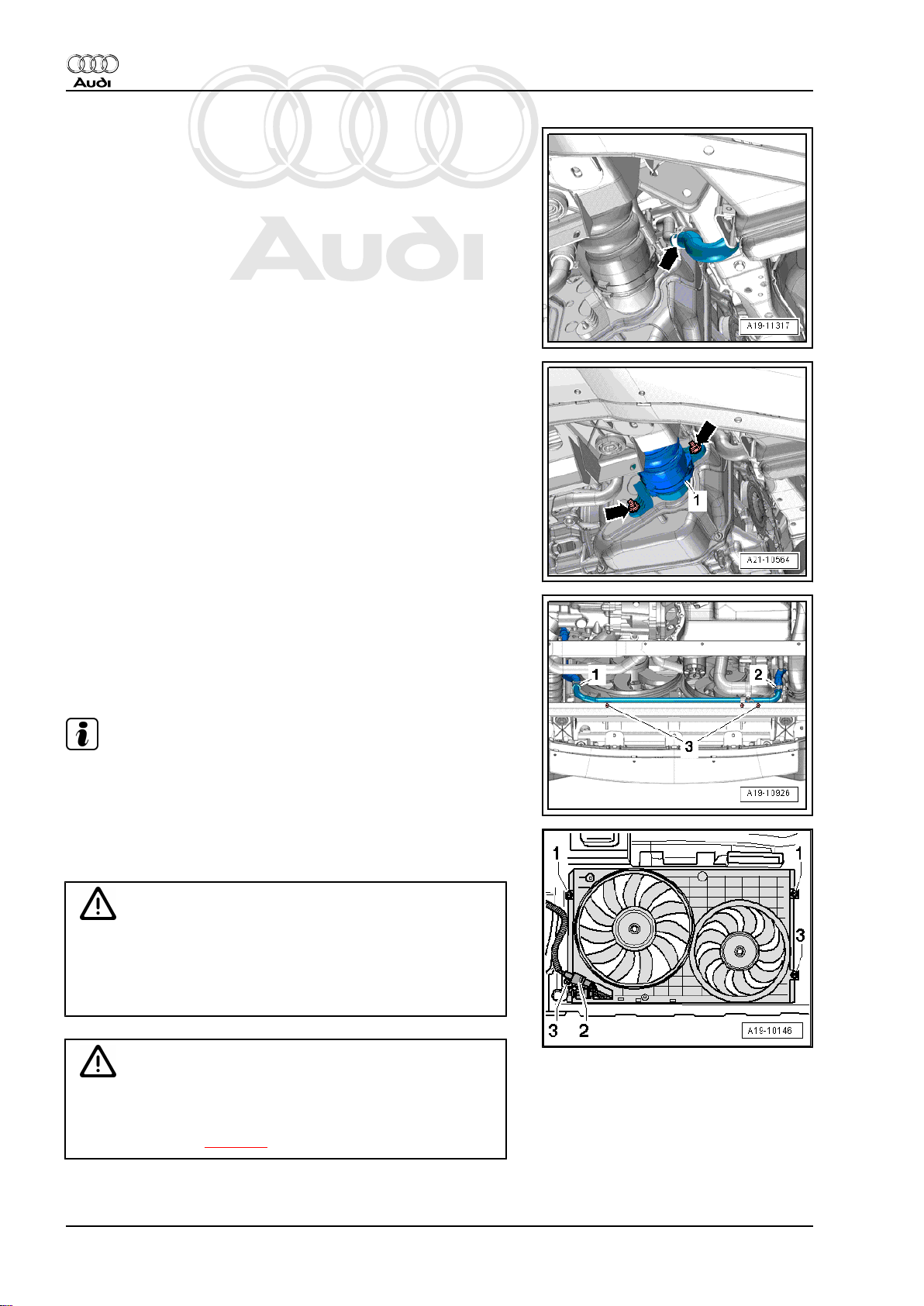
– Engage lifting tackle -2024 A- on gearbox and workshop hoist
-VAS 6100- .
Note
To adjust to the centre of gravity of the gearbox, the perforated
rails of the support hooks must be positioned as shown.
WARNING
Accident risk from loose components of lifting tackle.
♦ The support hooks and retaining pins on the lifting tackle
must be secured with locking pins -arrows-.
– Remove bolts -1, 3, 4, 5- securing gearbox to engine.
– Detach gearbox from engine.
Audi TT 2007 ➤
Note
Disregard -items 2, A, B-.
2. Separating engine from manual gearbox 31
Page 38

Protected by copyright. Copying for private or commercial purposes, in part or in whole, is not
permitted unless authorised by AUDI AG. AUDI AG does not guarantee or accept any liability
with respect to the correctness of information in this document. Copyright by AUDI AG.
Audi TT 2007 ➤
5-cylinder direct petrol injection engine (2.5 ltr. 4-valve turbo), mechanics - Edition 12.2010
3 Separating engine and dual-clutch
gearbox
Special tools and workshop equipment required
♦ Lifting tackle -2024 A-
♦ Eye-head bolt -3368-
♦ Workshop hoist -VAS 6100-
♦ Puller for ATF-supply -T40123 A-
32 Rep. gr.10 - Removing and installing engine
Page 39

Protected by copyright. Copying for private or commercial purposes, in part or in whole, is not
permitted unless authorised by AUDI AG. AUDI AG does not guarantee or accept any liability
with respect to the correctness of information in this document. Copyright by AUDI AG.
5-cylinder direct petrol injection engine (2.5 ltr. 4-valve turbo), mechanics - Edition 12.2010
Procedure
• Engine/gearbox assembly removed and attached to engine
support -T03000- .
– Remove bevel box ⇒ Rep. gr. 34 .
– Remove starter ⇒ Electrical system; Rep. gr. 27 .
– Remove nut -arrow- and move electrical wiring harness clear.
– Move breather hose -1- clear -arrows-.
Audi TT 2007 ➤
– Remove eye on puller for ATF-supply -T40123 A- and screw
into lower threaded hole for starter bolt as far as stop.
– Secure eye-head bolt -3368- to housing bore of gearbox with
two lock nuts -1-.
– Attach lifting tackle -2024 A- to both eyes and to workshop
hoist -VAS 6100- as shown in illustration.
Note
To adjust to the centre of gravity of the gearbox, the perforated
rails of the support hooks must be positioned as shown.
WARNING
Accident risk from loose components of lifting tackle.
♦ The support hooks and retaining pins on the lifting tackle
must be secured with locking pins -arrows-.
3. Separating engine and dual-clutch gearbox 33
Page 40

Protected by copyright. Copying for private or commercial purposes, in part or in whole, is not
permitted unless authorised by AUDI AG. AUDI AG does not guarantee or accept any liability
with respect to the correctness of information in this document. Copyright by AUDI AG.
Audi TT 2007 ➤
5-cylinder direct petrol injection engine (2.5 ltr. 4-valve turbo), mechanics - Edition 12.2010
– Remove bolts -1 ... 8- securing gearbox to engine.
– Detach gearbox from engine.
Note
Disregard -item A-.
34 Rep. gr.10 - Removing and installing engine
Page 41

Protected by copyright. Copying for private or commercial purposes, in part or in whole, is not
permitted unless authorised by AUDI AG. AUDI AG does not guarantee or accept any liability
with respect to the correctness of information in this document. Copyright by AUDI AG.
5-cylinder direct petrol injection engine (2.5 ltr. 4-valve turbo), mechanics - Edition 12.2010
4 Securing engine to engine and gear‐
box support
Special tools and workshop equipment required
♦ Lifting tackle -2024 A-
♦ Engine and gearbox support -VAS 6095-
Audi TT 2007 ➤
♦ Workshop hoist -VAS 6100-
♦ Engine bracket -T03001-
4. Securing engine to engine and gearbox support 35
Page 42

Protected by copyright. Copying for private or commercial purposes, in part or in whole, is not
permitted unless authorised by AUDI AG. AUDI AG does not guarantee or accept any liability
with respect to the correctness of information in this document. Copyright by AUDI AG.
Audi TT 2007 ➤
5-cylinder direct petrol injection engine (2.5 ltr. 4-valve turbo), mechanics - Edition 12.2010
Procedure
• Gearbox detached from engine.
– Secure engine support -T03001- to cylinder block.
1 - 40 Nm
2 - 25 Nm
3 - 40 Nm
– Engage lifting tackle -2024 A- on engine and workshop hoist
-VAS 6100- .
Note
To adjust to the centre of gravity of the assembly, the perforated
rails of the support hooks must be positioned as shown.
WARNING
Accident risk from loose components of lifting tackle.
♦ The support hooks and retaining pins on the lifting tackle
must be secured with locking pins -arrows-.
– Lift engine off engine bracket -T03000- using workshop hoist
-VAS 6100- .
– Secure engine to engine and gearbox support -VAS 6095- us‐
ing engine bracket -T03001- .
36 Rep. gr.10 - Removing and installing engine
Page 43

Protected by copyright. Copying for private or commercial purposes, in part or in whole, is not
permitted unless authorised by AUDI AG. AUDI AG does not guarantee or accept any liability
with respect to the correctness of information in this document. Copyright by AUDI AG.
5-cylinder direct petrol injection engine (2.5 ltr. 4-valve turbo), mechanics - Edition 12.2010
5 Installing engine
Tightening torques
Note
♦
Tightening torques apply only to lightly greased, oiled,
phosphated or black-finished nuts and bolts.
♦
Additional lubricants such as engine or gearbox oil may be
used, but do not use lubricants containing graphite.
♦
Do not use degreased parts.
♦
Tolerance for tightening torques: ± 15%.
Component Nm
Bolts/nuts M6 10
M7 15
M8 22
M10 40
M12 65
Audi TT 2007 ➤
Manual gearbox to engine
Item Bolt Nm
1 M12x65 80
2 Securing starter ⇒ Electrical system; Rep.
gr. 27
3 M10x65 40
4 M10x75 40
5
1)
M12x95 80
A, B Dowel sleeves for centralising
1)
•
Screwed into gearbox from engine side
5. Installing engine 37
Page 44

Protected by copyright. Copying for private or commercial purposes, in part or in whole, is not
permitted unless authorised by AUDI AG. AUDI AG does not guarantee or accept any liability
with respect to the correctness of information in this document. Copyright by AUDI AG.
Audi TT 2007 ➤
5-cylinder direct petrol injection engine (2.5 ltr. 4-valve turbo), mechanics - Edition 12.2010
Dual-clutch gearbox to engine
Item Bolt Nm
1 M12x65 80
2, 3, 4 M12x70 80
5, 6, 7 M10x60 40
8
1)
M12x95 80
A Dowel sleeves for centralising
1)
•
Screwed into gearbox from engine side
Procedure
• Engine/gearbox assembly attached to engine bracket T10012- .
Note
♦
Renew the bolts tightened with specified tightening angle.
♦
Renew self-locking nuts and bolts as well as seals, gaskets
and O-rings.
♦
Hose connections and air pipes and hoses must be free of oil
and grease before assembly.
♦
Secure all hose connections with the correct type of hose clips
(same as original equipment) ⇒ Electronic parts catalogue .
♦
To ensure that the air hoses can be properly secured at their
connections, spray rust remover onto the worm thread of used
hose clips before installing.
♦
Routing and attachment of pipes, hoses and wiring in engine
compartment ⇒ page 7 .
♦
Fit all cable ties in the original positions when installing.
Vehicles with manual gearbox:
– If not already fitted, install dowel sleeves -A, B- for centring
engine and gearbox in cylinder block.
– Renew clutch release bearing if worn ⇒ Rep. gr. 30 .
– Lubricate splines of gearbox input shaft lightly with grease for
clutch plate splines ⇒ Electronic parts catalogue .
– Make sure that clutch plate is properly centred.
38 Rep. gr.10 - Removing and installing engine
Page 45

Protected by copyright. Copying for private or commercial purposes, in part or in whole, is not
permitted unless authorised by AUDI AG. AUDI AG does not guarantee or accept any liability
with respect to the correctness of information in this document. Copyright by AUDI AG.
5-cylinder direct petrol injection engine (2.5 ltr. 4-valve turbo), mechanics - Edition 12.2010
Vehicles with dual clutch gearbox:
– If not already fitted, install dowel sleeves -A- for centring en‐
gine and gearbox in cylinder block.
All vehicles (continued):
– Secure gearbox to engine.
– Secure bracket for bevel box ⇒ Rep. gr. 34 .
– Install coolant pipe (left-side) ⇒ page 184 .
– Guide engine/gearbox assembly into body.
– Install engine mountings ⇒ page 42 .
Vehicles with manual gearbox:
– Initially screw in bolts -arrows- for gearbox mounting by hand
until they make contact.
Audi TT 2007 ➤
Vehicles with dual clutch gearbox:
– Initially screw in bolts -arrows- for gearbox mounting by hand
until they make contact.
All vehicles (continued):
– Detach engine support -T03000- from engine.
– Install pendulum support ⇒ Rep. gr. 34 .
Caution
Make sure not to damage the oil seal -arrow- in the propshaft
flange.
♦ Push the propshaft horizontally to the rear as far as pos‐
sible.
Note
The propshaft must be renewed if oil seal is damaged.
– Push engine/gearbox assembly towards plenum chamber par‐
tition panel, guiding pin on bevel box flange carefully into
propshaft flange.
5. Installing engine 39
Page 46

Protected by copyright. Copying for private or commercial purposes, in part or in whole, is not
permitted unless authorised by AUDI AG. AUDI AG does not guarantee or accept any liability
with respect to the correctness of information in this document. Copyright by AUDI AG.
Audi TT 2007 ➤
5-cylinder direct petrol injection engine (2.5 ltr. 4-valve turbo), mechanics - Edition 12.2010
– Secure propshaft with flexible coupling to bevel box ⇒ Rear
final drive 02D, 0AV, 0BR and 0BY; Rep. gr. 39 .
Remaining installation steps are carried out in reverse sequence;
note the following:
– Install catalytic converters ⇒ page 226 .
– Install starter catalytic converter ⇒ page 225 .
– Install wishbones and drive shafts ⇒ Rep. gr. 40 .
– Install heat shield for drive shaft ⇒ Rep. gr. 39 .
Vehicles with manual gearbox:
– Installing and adjusting selector mechanism ⇒ Rep. gr. 34 .
Caution
Risk of contamination by escaping brake fluid.
♦ Do not operate clutch pedal before attaching pipe/hose
assembly to bleeder connection on clutch slave cylinder.
– Connect pipe/hose assembly to bleeder connection on clutch
slave cylinder and bleed clutch system ⇒ Rep. gr. 30 .
Vehicles with dual clutch gearbox:
– Install selector lever cable ⇒ Rep. gr. 34 .
All vehicles (continued):
– Install coolant pipe (right-side) ⇒ page 182 .
– Install radiator ⇒ page 194 .
– Install air pipes ⇒ page 216 .
– Install idler rollers and poly V-belt tensioner ⇒ page 53 .
– Install alternator ⇒ Electrical system; Rep. gr. 27 .
– Install poly V-belt for alternator and coolant pump
⇒ page 56 .
– Install air conditioner compressor ⇒ Rep. gr. 87 .
– Install poly V-belt for air conditioner compressor
⇒ page 55 .
– Install starter ⇒ Electrical system; Rep. gr. 27 .
– Install noise insulation frame ⇒ Rep. gr. 50 .
– Install noise insulation and front wheel housing liners (bottom
sections) ⇒ Rep. gr. 66 .
– Fit front wheels ⇒ Wheels and tyres; Rep. gr. 44 .
– Adjust assembly mountings ⇒ page 45 .
– Install engine control unit and air cleaner housing ⇒ Rep. gr.
24 .
– Install charge pressure sender -G31- / intake air temperature
sender 2 -G299- ⇒ page 205 .
– Electrical connections and routing ⇒ Current flow diagrams,
Electrical fault finding and Fitting locations.
– Observe notes on procedure for connecting the battery ⇒
Electrical system; Rep. gr. 27 .
– Check oil level ⇒ Maintenance ; Booklet 810 .
40 Rep. gr.10 - Removing and installing engine
Page 47

Protected by copyright. Copying for private or commercial purposes, in part or in whole, is not
permitted unless authorised by AUDI AG. AUDI AG does not guarantee or accept any liability
with respect to the correctness of information in this document. Copyright by AUDI AG.
5-cylinder direct petrol injection engine (2.5 ltr. 4-valve turbo), mechanics - Edition 12.2010
Caution
Risk of irreparable damage to control units because of exces‐
sive voltage.
♦ Never use battery charging equipment for boost starting.
– Fill up with coolant ⇒ page 166 .
Note
Drained-off coolant may only be used again if the original cylinder
head and cylinder block are re-installed.
Audi TT 2007 ➤
5. Installing engine 41
Page 48

Protected by copyright. Copying for private or commercial purposes, in part or in whole, is not
permitted unless authorised by AUDI AG. AUDI AG does not guarantee or accept any liability
with respect to the correctness of information in this document. Copyright by AUDI AG.
Audi TT 2007 ➤
5-cylinder direct petrol injection engine (2.5 ltr. 4-valve turbo), mechanics - Edition 12.2010
6 Assembly mountings
Overview
♦ ⇒ „6.1 Assembly mountings - exploded view“, page 42
♦ ⇒ „6.2 Checking adjustment of assembly mountings (engine/
gearbox mountings)“, page 43
♦ ⇒ „6.3 Adjusting assembly mountings“, page 45
♦ ⇒ „6.4 Removing and installing engine mountings“,
page 49
6.1 Assembly mountings - exploded view
1 - Bolt
❑ Renew
❑ 40 Nm + turn 90° further
2 - Bolt
❑ Renew
❑ 40 Nm + turn 90° further
3 - Bolt
❑ Renew
❑ 40 Nm + turn 90° further
4 - Bracket
❑ For activated charcoal
filter
5 - Bolt
❑ Tightening torque
⇒ Item 11 (page 182)
6 - Nut
❑ 8 Nm
7 - Engine mounting
❑ Checking adjustment
⇒ page 43
❑ Adjusting ⇒ page 45
❑ Removing and installing
⇒ page 49
8 - Connecting bracket
9 - Bolt
❑ Renew
❑ 20 Nm + turn 90° further
10 - Bolt
❑ Renew
❑ 20 Nm + turn 90° further
11 - Bolt
❑ Renew
❑ 40 Nm + turn 90° further
12 - Pendulum support
❑ Removing and installing ⇒ Rep. gr. 34
42 Rep. gr.10 - Removing and installing engine
Page 49

Protected by copyright. Copying for private or commercial purposes, in part or in whole, is not
permitted unless authorised by AUDI AG. AUDI AG does not guarantee or accept any liability
with respect to the correctness of information in this document. Copyright by AUDI AG.
5-cylinder direct petrol injection engine (2.5 ltr. 4-valve turbo), mechanics - Edition 12.2010
13 - Bolt
❑ Tightening torque ⇒ Rep. gr. 34
14 - Bolt
❑ Tightening torque ⇒ Rep. gr. 34
15 - Bolt
❑ Tightening torque ⇒ Rep. gr. 34
16 - Bolt
❑ Tightening torque ⇒ Rep. gr. 34
17 - Bolt
❑ Tightening torque ⇒ Rep. gr. 34
18 - Gearbox mounting
❑ Checking adjustment ⇒ page 43
❑ Adjusting ⇒ page 45
❑ Removing and installing ⇒ Rep. gr. 34
6.2 Checking adjustment of assembly mountings (engine/gearbox mountings)
Audi TT 2007 ➤
Special tools and workshop equipment required
♦ Gauge -T40226-
Procedure
– Lift off engine cover panel -1- -arrows-.
6. Assembly mountings 43
Page 50

Protected by copyright. Copying for private or commercial purposes, in part or in whole, is not
permitted unless authorised by AUDI AG. AUDI AG does not guarantee or accept any liability
with respect to the correctness of information in this document. Copyright by AUDI AG.
Audi TT 2007 ➤
5-cylinder direct petrol injection engine (2.5 ltr. 4-valve turbo), mechanics - Edition 12.2010
– Remove air cleaner housing ⇒ Rep. gr. 24 .
Vehicles with manual gearbox:
– Open wiring duct brackets -arrows-.
– Cut through cable ties and press electrical wiring to side.
– Unclip wiring duct.
– Fit gauge -T40226- onto bolt heads of gearbox mounting (left-
side) and press in.
– Engage bridge of -T40226- onto rib on gearbox casting
-arrow- as shown in illustration.
• Distance of gap between adjusting tool and gearbox mounting
must be equal at front and rear.
• Distance -x- rear = -x- front (parallel) or
• Dimension -x- rear = dimension -x- front = „0“ (no gap).
44 Rep. gr.10 - Removing and installing engine
Page 51

Protected by copyright. Copying for private or commercial purposes, in part or in whole, is not
permitted unless authorised by AUDI AG. AUDI AG does not guarantee or accept any liability
with respect to the correctness of information in this document. Copyright by AUDI AG.
5-cylinder direct petrol injection engine (2.5 ltr. 4-valve turbo), mechanics - Edition 12.2010
Vehicles with dual clutch gearbox:
– Ensure that edges of support arm (on gearbox side) -1- and
gearbox mounting -2- are parallel.
• Dimension -x- = dimension -x-.
All vehicles (continued):
– Check installation position at engine mounting:
• The distance -a- between support arm and engine mounting
must be at least 9 mm.
Note
Audi TT 2007 ➤
Distance -a- can be checked using a ∅ 9 mm drill bit or similar.
– If the distance measured is too small, the assembly mounting
must be adjusted ⇒ page 45 .
6.3 Adjusting assembly mountings
Special tools and workshop equipment required
♦ Support bracket -10 - 222 A-
♦ Adapter -10 - 222 A /20-
6. Assembly mountings 45
Page 52

Protected by copyright. Copying for private or commercial purposes, in part or in whole, is not
permitted unless authorised by AUDI AG. AUDI AG does not guarantee or accept any liability
with respect to the correctness of information in this document. Copyright by AUDI AG.
Audi TT 2007 ➤
5-cylinder direct petrol injection engine (2.5 ltr. 4-valve turbo), mechanics - Edition 12.2010
♦ Gauge -T40226-
Procedure
– Loosen bolts -1, 2, 3- for pendulum support approx. 1 turn (do
not remove).
– Lift off engine cover panel -1- -arrows-.
– Remove air cleaner housing ⇒ Rep. gr. 24 .
46 Rep. gr.10 - Removing and installing engine
Page 53

Protected by copyright. Copying for private or commercial purposes, in part or in whole, is not
permitted unless authorised by AUDI AG. AUDI AG does not guarantee or accept any liability
with respect to the correctness of information in this document. Copyright by AUDI AG.
5-cylinder direct petrol injection engine (2.5 ltr. 4-valve turbo), mechanics - Edition 12.2010
– Position support bracket -10 - 222 A- on top edges of body
flanges as shown in illustration.
• One spindle -10 - 222 A /11- should be at front, one at rear.
WARNING
Risk of accident.
♦ The support hooks and retaining pin on the lifting tackle
must be secured with a locking pin -arrow-.
– Attach spindle -10 - 222 A /11- (front) with adapter -10 - 222
A /20- to engine lifting eye (front left).
– Attach spindle -10 - 222 A /11- (rear) to engine lifting eye (rear
left).
– Apply light tension to spindles.
• The engine must be positioned in installation position, assem‐
bly mountings must not be under load.
Vehicles with manual gearbox:
– Open wiring duct brackets -arrows-.
– Cut through cable ties and press electrical wiring to side.
– Unclip wiring duct.
Audi TT 2007 ➤
– Remove bolts -arrows- securing gearbox mounting.
– Renew all three bolts one by one and screw in by hand until
they make contact.
6. Assembly mountings 47
Page 54

Protected by copyright. Copying for private or commercial purposes, in part or in whole, is not
permitted unless authorised by AUDI AG. AUDI AG does not guarantee or accept any liability
with respect to the correctness of information in this document. Copyright by AUDI AG.
Audi TT 2007 ➤
5-cylinder direct petrol injection engine (2.5 ltr. 4-valve turbo), mechanics - Edition 12.2010
– Fit gauge -T40226- onto bolt heads of gearbox mounting (left-
side) and press in.
– Engage bridge of gauge -T40226- onto rib on gearbox casting
-arrow- as shown in illustration.
– Place engine/gearbox assembly in installation position; en‐
sure that it is free of stress by shaking assembly to align it.
• Distance of gap between adjusting tool and gearbox mounting
must be equal at front and rear.
• Distance -x- rear = -x- front (parallel) or
• Dimension -x- rear = dimension -x- front = „0“ (no gap).
– Check installation position at engine mounting:
• The distance -a- between support arm and engine mounting
must be at least 9 mm.
Note
Distance -a- can be checked using a ∅ 9 mm drill bit or similar.
– Move engine/gearbox assembly sideways if necessary.
– Tighten gearbox mounting bolts -arrows- with fitted gauge -
T40226- ⇒ Rep. gr. 34 .
Vehicles with dual clutch gearbox:
– Remove bolts -arrows- securing gearbox mounting.
– Renew all three bolts one by one and screw in by hand until
they make contact.
48 Rep. gr.10 - Removing and installing engine
Page 55

Protected by copyright. Copying for private or commercial purposes, in part or in whole, is not
permitted unless authorised by AUDI AG. AUDI AG does not guarantee or accept any liability
with respect to the correctness of information in this document. Copyright by AUDI AG.
5-cylinder direct petrol injection engine (2.5 ltr. 4-valve turbo), mechanics - Edition 12.2010
– Ensure that edges of support arm (on gearbox side) -1- and
gearbox mounting -2- are parallel.
• Dimension -x- = dimension -x-.
– Tighten gearbox mounting bolts ⇒ Rep. gr. 34 .
– Check installation position at engine mounting:
• The distance -a- between support arm and engine mounting
must be at least 9 mm.
Note
Distance -a- can be checked using a ∅ 9 mm drill bit or similar.
Audi TT 2007 ➤
– Move engine/gearbox assembly sideways if necessary.
All vehicles (continued):
Installation is carried out in the reverse order; note the following:
– Tighten bolts -1, 2, 3- for pendulum support ⇒ Rep. gr. 34 .
– Install air cleaner housing ⇒ Rep. gr. 24 .
6.4 Removing and installing engine mount‐
ings
Special tools and workshop equipment required
♦ Support bracket -10 - 222 A-
6. Assembly mountings 49
Page 56

Protected by copyright. Copying for private or commercial purposes, in part or in whole, is not
permitted unless authorised by AUDI AG. AUDI AG does not guarantee or accept any liability
with respect to the correctness of information in this document. Copyright by AUDI AG.
Audi TT 2007 ➤
5-cylinder direct petrol injection engine (2.5 ltr. 4-valve turbo), mechanics - Edition 12.2010
Removing
– Remove front wheel (right-side) ⇒ Wheels and tyres; Rep. gr.
44 .
– Remove bottom section of front wheel housing liner (right-
side) ⇒ Rep. gr. 66 .
– Remove one bolt of front wheel housing (right-side).
– Release activated charcoal filter -arrow B-, lift off -arrow A- and
move clear to one side with hose -1- connected.
Note
Disregard -item 2-.
– Remove bolts -arrows- and detach bracket for activated char‐
coal filter.
Note
Disregard -item 1-.
– Remove bolts -arrows-.
– Detach electrical connector -1- for coolant shortage indicator
switch -F66- and move coolant expansion tank with coolant
pipe (right-side) to side.
50 Rep. gr.10 - Removing and installing engine
Page 57

Protected by copyright. Copying for private or commercial purposes, in part or in whole, is not
permitted unless authorised by AUDI AG. AUDI AG does not guarantee or accept any liability
with respect to the correctness of information in this document. Copyright by AUDI AG.
5-cylinder direct petrol injection engine (2.5 ltr. 4-valve turbo), mechanics - Edition 12.2010
– Position support bracket -10 - 222 A- on top edges of body
flanges as shown in illustration.
• The spindle -10 - 222 A /11- is located at the front.
– Attach hook of spindle to engine lifting eye (right-side).
– Apply light tension to spindle.
– Remove bolts -1- and -arrows- for engine mounting (left-side).
Note
The bolt at the rear of the cylinder block can be accessed from
the wheel housing side.
Installing
• Tightening torques
⇒ „6.1 Assembly mountings - exploded view“, page 42
– Check adjustment of assembly mountings (engine/gearbox
mountings) ⇒ page 43 .
Remaining installation steps are carried out in reverse sequence;
note the following:
– Install bottom section of front wheel housing liner ⇒ Rep. gr.
66 .
– Fit front wheel ⇒ Wheels and tyres; Rep. gr. 44 .
Audi TT 2007 ➤
6. Assembly mountings 51
Page 58

Protected by copyright. Copying for private or commercial purposes, in part or in whole, is not
permitted unless authorised by AUDI AG. AUDI AG does not guarantee or accept any liability
with respect to the correctness of information in this document. Copyright by AUDI AG.
Audi TT 2007 ➤
5-cylinder direct petrol injection engine (2.5 ltr. 4-valve turbo), mechanics - Edition 12.2010
13 – Crankshaft group
1 Cylinder block (pulley end)
Overview
♦ ⇒ „1.1 Poly V-belt drive, bracket for ancillaries - exploded
view“, page 53
♦ ⇒ „1.2 Removing and installing poly V-belt for A/C compres‐
sor“, page 55
♦ ⇒ „1.3 Removing and installing poly V-belt for alternator and
coolant pump“, page 56
♦ ⇒ „1.4 Removing and installing poly V-belt tensioner for air
conditioner compressor“, page 57
♦ ⇒ „1.5 Removing and installing poly V-belt tensioner for alter‐
nator and coolant pump“, page 57
♦ ⇒ „1.6 Removing and installing bracket for ancillaries“,
page 58
♦ ⇒ „1.7 Removing and installing vibration damper“, page 59
♦ ⇒ „1.8 Sealing flange (pulley end) - exploded view“,
page 62
♦ ⇒ „1.9 Renewing sealing flange (pulley end)“, page 62
52 Rep. gr.13 - Crankshaft group
Page 59

Protected by copyright. Copying for private or commercial purposes, in part or in whole, is not
permitted unless authorised by AUDI AG. AUDI AG does not guarantee or accept any liability
with respect to the correctness of information in this document. Copyright by AUDI AG.
5-cylinder direct petrol injection engine (2.5 ltr. 4-valve turbo), mechanics - Edition 12.2010
1.1 Poly V-belt drive, bracket for ancillaries - exploded view
1 - Bolt
❑ 35 Nm
2 - Bolt
❑ Renew
❑ 50 Nm + turn 90° further
3 - Vibration damper
❑ Removing and installing
⇒ page 59
❑ Can only be installed in
one position
4 - Poly V-belt for air condition‐
er compressor
❑ Check for wear
❑ Before removing, mark
direction of rotation with
chalk or felt-tipped pen
❑ Removing and installing
⇒ page 55
❑ Do not kink
❑ When installing, make
sure it is properly seated
on pulleys.
5 - Tensioner
❑ For poly V-belt for air
conditioner compressor
❑ Removing and installing
⇒ page 57
6 - Bolt
❑ 35 Nm
7 - Tensioner
❑ For poly V-belt for alter‐
nator and coolant pump
❑ Removing and installing ⇒ page 57
8 - Poly V-belt for alternator and coolant pump
❑ Check for wear
❑ Before removing, mark direction of rotation with chalk or felt-tipped pen
❑ Removing and installing ⇒ page 56
❑ Do not kink
❑ When installing, make sure it is properly seated on pulleys.
9 - Idler roller
10 - Bolt
❑ Tightening torque ⇒ Item 2 (page 173)
11 - Coolant pump
❑ Removing and installing ⇒ page 176
12 - Bolt
❑ 8 Nm
13 - Dowel sleeves
❑ For bracket for ancillaries
Audi TT 2007 ➤
1. Cylinder block (pulley end) 53
Page 60

Protected by copyright. Copying for private or commercial purposes, in part or in whole, is not
permitted unless authorised by AUDI AG. AUDI AG does not guarantee or accept any liability
with respect to the correctness of information in this document. Copyright by AUDI AG.
Audi TT 2007 ➤
5-cylinder direct petrol injection engine (2.5 ltr. 4-valve turbo), mechanics - Edition 12.2010
14 - Bracket for ancillaries
❑ Removing and installing ⇒ page 58
15 - Bolt
❑ Different lengths
❑ Tightening torque and sequence ⇒ page 54
16 - Bolt
❑ Tightening torque ⇒ Electrical system; Rep. gr. 27
17 - Alternator
❑ Removing and installing ⇒ Electrical system; Rep. gr. 27
18 - Sliding bush
19 - Idler roller
20 - Bolt
❑ 23 Nm
21 - Dowel sleeves
❑ For air conditioner compressor
22 - Air conditioner compressor
❑ With double-sided poly V-belt pulley
❑ Removing and installing ⇒ Rep. gr. 87
23 - Bolt
❑ Tightening torque ⇒ Rep. gr. 87
Bracket for ancillaries - tightening torque and tightening sequence
– Renew bolts for bracket for ancillaries and fit as follows:
♦ Bolts -1, 2, 3, 6- M8x30.
♦ Bolt -4- M8x60.
♦ Bolt -5- M8x110.
– Tighten bolts in 2 stages in the sequence shown:
Stage Bolts Tightening torque
1. -1 … 6- Screw in bolts by hand until they make
contact
2. -1 … 6- 23 Nm
54 Rep. gr.13 - Crankshaft group
Page 61

Protected by copyright. Copying for private or commercial purposes, in part or in whole, is not
permitted unless authorised by AUDI AG. AUDI AG does not guarantee or accept any liability
with respect to the correctness of information in this document. Copyright by AUDI AG.
5-cylinder direct petrol injection engine (2.5 ltr. 4-valve turbo), mechanics - Edition 12.2010
1.2 Removing and installing poly V-belt for A/C compressor
Removing
– Remove front wheel (right-side) ⇒ Wheels and tyres; Rep. gr.
44 .
– Remove bottom section of front wheel housing liner (right-
side) ⇒ Rep. gr. 66 .
Caution
If a used belt runs in the opposite direction when it is refitted,
this can cause breakage.
Audi TT 2007 ➤
♦ Before removing, mark direction of rotation of poly V-belt
for air conditioner compressor with chalk or felt-tipped pen
for re-installation.
– To slacken poly V-belt turn tensioner in clockwise direction
-arrow-.
– Detach poly V-belt for air conditioner compressor and release
tensioner.
Installing
Installation is carried out in the reverse order; note the following:
– Swivel tensioner in clockwise direction -arrow-.
– Fit poly V-belt on poly V-belt pulleys (on air conditioner pulley
last).
1 - Vibration damper
2 - Tensioner
3 - Air conditioner compressor
– Slacken tensioner.
– Check that poly V-belt is properly seated.
– Start engine and check that belt runs properly.
– Install bottom section of front wheel housing liner ⇒ Rep. gr.
66 .
– Fit front wheel ⇒ Wheels and tyres; Rep. gr. 44 .
1. Cylinder block (pulley end) 55
Page 62

Protected by copyright. Copying for private or commercial purposes, in part or in whole, is not
permitted unless authorised by AUDI AG. AUDI AG does not guarantee or accept any liability
with respect to the correctness of information in this document. Copyright by AUDI AG.
Audi TT 2007 ➤
5-cylinder direct petrol injection engine (2.5 ltr. 4-valve turbo), mechanics - Edition 12.2010
1.3 Removing and installing poly V-belt for alternator and coolant pump
Removing
– Remove poly V-belt for air conditioner compressor
⇒ page 55 .
– Release activated charcoal filter -arrow B-, lift off -arrow A- and
move clear to one side with hose -1- connected.
Note
Disregard -item 2-.
Caution
If a used belt runs in the opposite direction when it is refitted,
this can cause breakage.
♦ Before removing, mark direction of rotation of poly V-belt
for alternator and coolant pump with chalk or felt-tipped
pen for re-installation.
– To slacken poly V-belt turn tensioner in clockwise direction
-arrow-.
– Detach poly V-belt for alternator and coolant pump and re‐
lease tensioner.
Installing
Installation is carried out in the reverse order; note the following:
– Swivel tensioner in clockwise direction -arrow-.
– Fit poly V-belt on poly V-belt pulleys (on alternator pulley last).
1 - Tensioner
2 - Coolant pump
3 - Idler roller
4 - Alternator
5 - Idler roller
6 - Air conditioner compressor
– Slacken tensioner.
– Check that poly V-belt is properly seated.
– Install poly V-belt for air conditioner compressor ⇒ page 55 .
56 Rep. gr.13 - Crankshaft group
Page 63

Protected by copyright. Copying for private or commercial purposes, in part or in whole, is not
permitted unless authorised by AUDI AG. AUDI AG does not guarantee or accept any liability
with respect to the correctness of information in this document. Copyright by AUDI AG.
5-cylinder direct petrol injection engine (2.5 ltr. 4-valve turbo), mechanics - Edition 12.2010
1.4 Removing and installing poly V-belt ten‐
sioner for air conditioner compressor
Removing
– Remove poly V-belt for air conditioner compressor
⇒ page 55 .
– Remove front noise insulation -1- ⇒ Rep. gr. 66 .
– Remove bolts -arrows- and detach bracket -1- for auxiliary ra‐
diator.
Audi TT 2007 ➤
– Remove bolt -arrow- and take off tensioner.
Installing
Installation is carried out in the reverse order; note the following:
• Tightening torque
⇒ „1.1 Poly V-belt drive, bracket for ancillaries - exploded
view“, page 53
– Install bracket for auxiliary radiator ⇒ page 192 .
– Install front noise insulation ⇒ Rep. gr. 66 .
– Install poly V-belt for air conditioner compressor ⇒ page 55 .
1.5 Removing and installing poly V-belt ten‐
sioner for alternator and coolant pump
Removing
– Release activated charcoal filter -arrow B-, lift off -arrow A- and
move clear to one side with hose -1- connected.
Note
Disregard -item 2-.
1. Cylinder block (pulley end) 57
Page 64

Protected by copyright. Copying for private or commercial purposes, in part or in whole, is not
permitted unless authorised by AUDI AG. AUDI AG does not guarantee or accept any liability
with respect to the correctness of information in this document. Copyright by AUDI AG.
Audi TT 2007 ➤
5-cylinder direct petrol injection engine (2.5 ltr. 4-valve turbo), mechanics - Edition 12.2010
– To slacken poly V-belt turn tensioner in clockwise direction
-arrow-.
– Remove poly V-belt from alternator and release tensioner.
– Remove bolt -arrow- and take off tensioner.
Installing
Installation is carried out in the reverse order; note the following:
• Tightening torque
⇒ „1.1 Poly V-belt drive, bracket for ancillaries - exploded
view“, page 53
– Install poly V-belt for alternator and coolant pump
⇒ page 56 .
1.6 Removing and installing bracket for an‐
cillaries
Removing
– Remove poly V-belt tensioner for air conditioner compressor
⇒ page 57 .
– Remove alternator ⇒ Electrical system; Rep. gr. 27 .
– Remove engine mounting ⇒ page 49 .
– Remove noise insulation frame -arrow- together with rear
noise insulation ⇒ Rep. gr. 50 .
– Remove radiator cowl ⇒ page 200 .
58 Rep. gr.13 - Crankshaft group
Page 65

Protected by copyright. Copying for private or commercial purposes, in part or in whole, is not
permitted unless authorised by AUDI AG. AUDI AG does not guarantee or accept any liability
with respect to the correctness of information in this document. Copyright by AUDI AG.
5-cylinder direct petrol injection engine (2.5 ltr. 4-valve turbo), mechanics - Edition 12.2010
– Unplug electrical connector -1- on air conditioner compressor
regulating valve -N280- .
Caution
Danger of damage to refrigerant lines and hoses.
♦ Do NOT stretch, kink or bend refrigerant lines and hoses.
– Remove bolts -arrows-.
– Detach air conditioner compressor from bracket and tie up to
lock carrier.
– Remove bolt -arrow-.
– Remove bolts -1 ... 6- and detach bracket for ancillaries.
Installing
Installation is carried out in the reverse order; note the following:
– Tighten bolts for bracket for ancillaries ⇒ page 54 .
– Install air conditioner compressor ⇒ Rep. gr. 87 .
– Install radiator cowl ⇒ page 200 .
– Install noise insulation frame ⇒ Rep. gr. 50 .
– Install engine mountings ⇒ page 49 .
– Install alternator ⇒ Electrical system; Rep. gr. 27 .
– Install poly V-belt tensioner for air conditioner compressor
⇒ page 57 .
Audi TT 2007 ➤
1.7 Removing and installing vibration damp‐
er
Special tools and workshop equipment required
♦ Socket -T03003-
1. Cylinder block (pulley end) 59
Page 66

Protected by copyright. Copying for private or commercial purposes, in part or in whole, is not
permitted unless authorised by AUDI AG. AUDI AG does not guarantee or accept any liability
with respect to the correctness of information in this document. Copyright by AUDI AG.
Audi TT 2007 ➤
5-cylinder direct petrol injection engine (2.5 ltr. 4-valve turbo), mechanics - Edition 12.2010
♦ Locking pin -T40069-
Removing
– Remove poly V-belt for air conditioner compressor
⇒ page 55 .
– Remove noise insulation panel -1- and -2- ⇒ Rep. gr. 66 .
– Turn crankshaft with socket -T03003- in normal direction of
rotation -arrow- to „TDC position“.
• Notch -1- in socket -T03003- must be perpendicular to sealing
surface of sump.
• Marking -2- on vibration damper must be opposite marking
-3- on sealing flange.
– Unscrew plug -arrow- for „TDC“ marking from cylinder block.
60 Rep. gr.13 - Crankshaft group
Page 67

Protected by copyright. Copying for private or commercial purposes, in part or in whole, is not
permitted unless authorised by AUDI AG. AUDI AG does not guarantee or accept any liability
with respect to the correctness of information in this document. Copyright by AUDI AG.
5-cylinder direct petrol injection engine (2.5 ltr. 4-valve turbo), mechanics - Edition 12.2010
– Screw locking pin -T40069- into locating groove and tighten to
15 Nm. If necessary, turn crankshaft backwards and forwards
slightly to fully centralise locking pin.
– Unscrew bolts -arrow- and remove vibration damper.
Installing
Installation is carried out in the reverse order; note the following:
• Tightening torque
⇒ „1.1 Poly V-belt drive, bracket for ancillaries - exploded
view“, page 53
Audi TT 2007 ➤
Note
♦
Renew the bolts tightened with specified tightening angle.
♦
The vibration damper can only be fitted in one position.
– Remove locking pin -T40069- .
– Tighten plug for „TDC“ marking ⇒ page 72 .
– Install noise insulation panels ⇒ Rep. gr. 66 .
– Install poly V-belt for air conditioner compressor ⇒ page 55 .
1. Cylinder block (pulley end) 61
Page 68

Protected by copyright. Copying for private or commercial purposes, in part or in whole, is not
permitted unless authorised by AUDI AG. AUDI AG does not guarantee or accept any liability
with respect to the correctness of information in this document. Copyright by AUDI AG.
Audi TT 2007 ➤
5-cylinder direct petrol injection engine (2.5 ltr. 4-valve turbo), mechanics - Edition 12.2010
1.8 Sealing flange (pulley end) - exploded view
1 - Bolt
❑ Tightening torque
⇒ Item 2 (page 53)
2 - Vibration damper
❑ Removing and installing
⇒ page 59
❑ Can only be installed in
one position
3 - Sealing flange (pulley end)
❑ With centring collar
❑ Renewing ⇒ page 62
❑ Apply sealant when in‐
stalling; refer to ⇒ Elec‐
tronic parts catalogue
4 - Bolt
❑ Tightening torque and
sequence ⇒ page 62
Sealing flange (pulley end) - tightening torque and sequence
– Tighten bolts in 2 stages:
Stage Bolts Tightening torque
1. -arrow- Screw in bolts by hand until they make
contact.
2. -arrow- Tighten in stages and in diagonal se‐
quence; final torque 9 Nm.
1.9 Renewing sealing flange (pulley end)
Special tools and workshop equipment required
62 Rep. gr.13 - Crankshaft group
Page 69

Protected by copyright. Copying for private or commercial purposes, in part or in whole, is not
permitted unless authorised by AUDI AG. AUDI AG does not guarantee or accept any liability
with respect to the correctness of information in this document. Copyright by AUDI AG.
5-cylinder direct petrol injection engine (2.5 ltr. 4-valve turbo), mechanics - Edition 12.2010
♦ Assembly sleeve -T03004-
♦ Electric drill with plastic brush
♦ Safety goggles
♦ Sealant ⇒ Electronic parts catalogue
Procedure
– Remove vibration damper ⇒ page 59 .
– Remove noise insulation frame -arrow- together with rear
noise insulation ⇒ Rep. gr. 50 .
Audi TT 2007 ➤
– Remove bolts -1- and -2-.
– Release hose clips -arrows- and remove air pipe.
1. Cylinder block (pulley end) 63
Page 70

Protected by copyright. Copying for private or commercial purposes, in part or in whole, is not
permitted unless authorised by AUDI AG. AUDI AG does not guarantee or accept any liability
with respect to the correctness of information in this document. Copyright by AUDI AG.
Audi TT 2007 ➤
5-cylinder direct petrol injection engine (2.5 ltr. 4-valve turbo), mechanics - Edition 12.2010
– Remove bolts -arrows-.
– Carefully release sealing flange from bonded joint.
Note
Renew sealing flange.
Caution
Make sure sealant residue does not enter lubrication system.
♦ Cover open area of cylinder block with a cloth.
WARNING
Protect eyes against injuries.
♦ Wear safety goggles.
– Use e.g. rotating plastic brush to remove sealant residue on
cylinder block.
– Clean sealing surfaces and crankshaft journal; they must be
free of oil and grease.
Note
Do not additionally oil or grease sealing lip of oil seal in sealing
flange.
Caution
Risk of damage to oil seal in sealing flange.
♦ To make sure sealing lip of oil seal is folded over when
installing, the following procedures must be performed.
– Open out sealing lip of oil seal in sealing flange using assembly
sleeve -T03004- as shown in illustration.
• Small diameter faces oil seal.
– Detach assembly sleeve -T03004- after a short while, turn
over and insert in oil seal again.
• Large diameter faces oil seal.
• Assembly sleeve -T03004- must protrude by distance -a- at
inside of flange
• Distance -a- = approx. 3 mm.
64 Rep. gr.13 - Crankshaft group
Page 71

Protected by copyright. Copying for private or commercial purposes, in part or in whole, is not
permitted unless authorised by AUDI AG. AUDI AG does not guarantee or accept any liability
with respect to the correctness of information in this document. Copyright by AUDI AG.
5-cylinder direct petrol injection engine (2.5 ltr. 4-valve turbo), mechanics - Edition 12.2010
Note
Note the use-by date of the sealant.
– Cut off nozzle of tube at front marking (nozzle ∅ approx. 2
mm).
Caution
Make sure lubrication system is not clogged by excess sealant.
♦ The bead of sealant must not be thicker than specified.
– Apply bead of sealant -A- onto clean sealing surface of sealing
flange as shown in illustration.
• Width of sealant bead: 2.5 ... 3 mm
• The bead of sealant must project approx. 1.0 mm above the
sealing surface.
Audi TT 2007 ➤
Note
The sealing flange must be installed within 5 minutes after apply‐
ing the sealant.
– Use assembly sleeve -T03004- to carefully fit sealing flange
onto crankshaft journal and press onto cylinder block evenly
(note centring collar on left and right).
– Tighten sealing flange ⇒ page 62 .
– Install air pipe ⇒ page 216 .
– Install noise insulation frame ⇒ Rep. gr. 50 .
– Install vibration damper ⇒ page 59 .
1. Cylinder block (pulley end) 65
Page 72

Protected by copyright. Copying for private or commercial purposes, in part or in whole, is not
permitted unless authorised by AUDI AG. AUDI AG does not guarantee or accept any liability
with respect to the correctness of information in this document. Copyright by AUDI AG.
Audi TT 2007 ➤
5-cylinder direct petrol injection engine (2.5 ltr. 4-valve turbo), mechanics - Edition 12.2010
2 Cylinder block (gearbox end)
Overview
♦ ⇒ „2.1 Dual-mass flywheel - exploded view“, page 66
♦ ⇒ „2.2 Removing and installing dual-mass flywheel“,
page 67
♦ ⇒ „2.3 Renewing crankshaft oil seal (gearbox end)“,
page 68
Note
♦
When performing assembly work, secure engine to engine
and gearbox support ⇒ page 35 .
♦
Servicing clutch ⇒ Rep. gr. 30
2.1 Dual-mass flywheel - exploded view
1 - Bolt
❑ Renew
❑ 60 Nm + turn 90° further
2 - Dual-mass flywheel
❑ Different versions avail‐
able; for allocation refer
to ⇒ Electronic parts
catalogue
❑ Removing and installing
⇒ page 67
❑ Can only be installed in
one position
3 - Diamond-coated washer
❑ Must always be re‐
newed if bolts for dualmass flywheel are loos‐
ened
❑ Can only be installed in
one position
4 - Sender wheel
❑ For engine speed send‐
er -G28-
❑ Can only be installed in
one position
5 - Dowel pin
6 - Crankshaft oil seal (gearbox
end)
❑ Renewing ⇒ page 68
7 - Diamond-coated washer
❑ Must always be re‐
newed if bolts for dualmass flywheel are loos‐
ened
❑ Can only be installed in one position
66 Rep. gr.13 - Crankshaft group
Page 73

Protected by copyright. Copying for private or commercial purposes, in part or in whole, is not
permitted unless authorised by AUDI AG. AUDI AG does not guarantee or accept any liability
with respect to the correctness of information in this document. Copyright by AUDI AG.
5-cylinder direct petrol injection engine (2.5 ltr. 4-valve turbo), mechanics - Edition 12.2010
2.2 Removing and installing dual-mass fly‐
wheel
Special tools and workshop equipment required
♦ Counterhold tool -3067-
Removing
• Gearbox removed.
Audi TT 2007 ➤
Caution
Make sure dual-mass flywheel is not damaged.
♦ Remove bolts -B- using normal hand tools (do not use
pneumatic wrench or impact driver, etc.).
♦ When removing the bolts, make sure that the bolt heads
do not come into contact with the dual-mass flywheel.
♦ Rotate the dual-mass flywheel -A- so that the bolts -B-
align centrally with the holes -arrows-.
– Insert counterhold tool -3067- in hole on cylinder block
-item B-, slacken and remove bolts for dual-mass flywheel.
Installing
Installation is carried out in the reverse order; note the following:
• Tightening torque
⇒ „2.1 Dual-mass flywheel - exploded view“, page 66
Caution
Make sure friction is sufficient.
♦ Always renew diamond-coated washers
⇒ Item 3 (page 66) and ⇒ Item 7 (page 66) after loosening
bolts for dual-mass flywheel.
Note
♦
Renew the bolts tightened with specified tightening angle.
♦
Dual-mass flywheel with sender wheel and diamond-coated
washers can only be fitted in one position.
– Insert counterhold -3067- in hole on cylinder block -item A-.
2. Cylinder block (gearbox end) 67
Page 74

Protected by copyright. Copying for private or commercial purposes, in part or in whole, is not
permitted unless authorised by AUDI AG. AUDI AG does not guarantee or accept any liability
with respect to the correctness of information in this document. Copyright by AUDI AG.
Audi TT 2007 ➤
5-cylinder direct petrol injection engine (2.5 ltr. 4-valve turbo), mechanics - Edition 12.2010
2.3 Renewing crankshaft oil seal (gearbox end)
Special tools and workshop equipment required
♦ Fitting tool -T10122-
♦ Extractor tool -T20143/2-
Set up assembly sleeve -T10122/2- as follows:
– Machine drilling for dowel sleeve in assembly sleeve -
T10122/2- until dimension -a- = 8 mm.
Procedure
• Gearbox removed.
– Remove dual-mass flywheel ⇒ page 67 .
– Pry out oil seal using extractor tool -T20143/2- -arrow-.
– Clean contact surface and sealing surface.
68 Rep. gr.13 - Crankshaft group
Page 75

Protected by copyright. Copying for private or commercial purposes, in part or in whole, is not
permitted unless authorised by AUDI AG. AUDI AG does not guarantee or accept any liability
with respect to the correctness of information in this document. Copyright by AUDI AG.
5-cylinder direct petrol injection engine (2.5 ltr. 4-valve turbo), mechanics - Edition 12.2010
– Fit assembly aid -T10122/1- onto assembly sleeve -T10122/2-
and slide oil seal -A- onto assembly sleeve.
– Detach assembly aid.
– Fit assembly sleeve -T10122/2- with oil seal -1- onto crank‐
shaft.
Audi TT 2007 ➤
– Press in oil seal uniformly until flush all round using thrust
piece -T10122/3- .
– Install dual-mass flywheel ⇒ page 67 .
2. Cylinder block (gearbox end) 69
Page 76

Protected by copyright. Copying for private or commercial purposes, in part or in whole, is not
permitted unless authorised by AUDI AG. AUDI AG does not guarantee or accept any liability
with respect to the correctness of information in this document. Copyright by AUDI AG.
Audi TT 2007 ➤
5-cylinder direct petrol injection engine (2.5 ltr. 4-valve turbo), mechanics - Edition 12.2010
3 Crankshaft
Overview
♦ ⇒ „3.1 Crankshaft - exploded view“, page 70
♦ ⇒ „3.2 Crankshaft dimensions“, page 72
♦ ⇒ „3.3 Measuring axial clearance of crankshaft“, page 72
♦ ⇒ „3.4 Measuring radial clearance of crankshaft“, page 73
Note
♦
When performing assembly work, secure engine to engine
and gearbox support ⇒ page 35 .
♦
If large quantities of metal shavings or abrasion are found
when performing engine repairs, this may be an indication of
damage to the crankshaft or conrod bearings. To prevent fur‐
ther damage, the following steps are required after completion
of repair work: clean the oil galleries carefully and renew the
oil spray jets, engine oil cooler and oil filter.
3.1 Crankshaft - exploded view
1 - Bolt
❑ Renew
❑ 40 Nm + turn 90° further
2 - Bearing caps
❑ Bearing cap 1: Pulley
end
❑ Installation position: re‐
taining lugs on bearing
shells in cylinder block
and bearing caps must
be on the same side
3 - Bearing shell
❑ For bearing cap (without
oil groove)
❑ Mark used bearing
shells for re-installation
but not on bearing sur‐
face
❑ Bearing shells worn
down to base layer must
be renewed
❑ Insert new bearing
shells with correct col‐
our-coding ⇒ page 71
4 - Crankshaft
❑ Measuring axial clear‐
ance ⇒ page 72
❑ Measuring radial clear‐
ance ⇒ page 73
❑ Crankshaft dimensions
⇒ page 72
5 - Thrust washers
❑ For bearing No. 3
70 Rep. gr.13 - Crankshaft group
Page 77

Protected by copyright. Copying for private or commercial purposes, in part or in whole, is not
permitted unless authorised by AUDI AG. AUDI AG does not guarantee or accept any liability
with respect to the correctness of information in this document. Copyright by AUDI AG.
Audi TT 2007 ➤
5-cylinder direct petrol injection engine (2.5 ltr. 4-valve turbo), mechanics - Edition 12.2010
6 - Bearing shell
❑ For cylinder block (with oil groove)
❑ Mark used bearing shells for re-installation but not on bearing surface
❑ Bearing shells worn down to base layer must be renewed
❑ Install new bearing shells for the cylinder block with the correct coloured markings ⇒ page 71
7 - Cylinder block
Allocation of crankshaft bearing shells for cylinder block
♦ Bearing shells of the correct thickness are matched to the
bearings in the cylinder block at the factory. Coloured dots on
the side of the bearing shells are used to identify the bearing
shell thickness.
♦ Letter codes on the lower sealing surface of the cylinder block
indicate the thickness of the bearing shell to be fitted at each
location.
Letter on cylinder block Colour coding of bearing
G = Yellow
B = Blue
W = White
Note
The -arrow- points in direction of travel.
Allocation of crankshaft bearing shells for bearing caps
♦ Bearing shells of the correct thickness are assigned to the
bearing caps at the factory. Coloured dots on the side of the
bearing shells are used to identify the bearing shell thickness.
♦ The correct allocation of bearing shells to bearing cap is indi‐
cated by a sequence of letters on the pulley flange of the
crankshaft. The first letter in the sequence stands for bearing
„1“, the second letter for bearing „2“, etc.
Letter on crankshaft Colour coding of bearing
R = Red
G = Yellow
B = Blue
W = White
Note
The -arrow- points in direction of travel.
3. Crankshaft 71
Page 78

Protected by copyright. Copying for private or commercial purposes, in part or in whole, is not
permitted unless authorised by AUDI AG. AUDI AG does not guarantee or accept any liability
with respect to the correctness of information in this document. Copyright by AUDI AG.
Audi TT 2007 ➤
5-cylinder direct petrol injection engine (2.5 ltr. 4-valve turbo), mechanics - Edition 12.2010
Plug for „TDC“ marking - tightening torque
Note
Renew seal.
– Tighten plug -arrow- for „TDC“ marking to 45 Nm.
3.2 Crankshaft dimensions
Honing di‐
mension
Basic dimen‐
sion
Main bearing journal ∅mmConrod journal ∅
mm
58.000 – 0.022
– 0.042
47.800 – 0.022
– 0.042
3.3 Measuring axial clearance of crankshaft
Special tools and workshop equipment required
♦ Universal dial gauge bracket -VW 387-
♦ Dial gauge -VAS 6079-
72 Rep. gr.13 - Crankshaft group
Page 79

Protected by copyright. Copying for private or commercial purposes, in part or in whole, is not
permitted unless authorised by AUDI AG. AUDI AG does not guarantee or accept any liability
with respect to the correctness of information in this document. Copyright by AUDI AG.
5-cylinder direct petrol injection engine (2.5 ltr. 4-valve turbo), mechanics - Edition 12.2010
Procedure
– Secure dial gauge -VAS 6079- with universal dial gauge brack‐
et -VW 387- to cylinder block as shown in illustration.
– Apply dial gauge to crank web.
– Press crankshaft against dial gauge by hand and set gauge to
„0“.
– Push crankshaft away from dial gauge and read off value.
Axial clearance:
• New: 0.07 ... 0.21 mm.
• Wear limit: 0.30 mm.
3.4 Measuring radial clearance of crank‐
shaft
Special tools and workshop equipment required
♦ Plastigage
Procedure
Audi TT 2007 ➤
Note
♦
Mark used bearing shells for re-installation (but do not mark
bearing surface).
♦
Bearing shells worn down to the base layer must be renewed.
– Remove bearing cap.
– Clean bearing cap and bearing journal.
– Place a length of Plastigage corresponding to the width of the
bearing on the bearing journal or in the bearing shell.
• The Plastigage must be positioned in the centre of the bearing
shell.
– Fit bearing cap and tighten bolts to 40 Nm (do not turn further)
without rotating crankshaft.
– Remove bearing cap again.
– Compare width of Plastigage with measurement scale.
Radial clearance:
• New: 0.023 ... 0.043 mm.
• Wear limit: 0.07 mm.
3. Crankshaft 73
Page 80

Protected by copyright. Copying for private or commercial purposes, in part or in whole, is not
permitted unless authorised by AUDI AG. AUDI AG does not guarantee or accept any liability
with respect to the correctness of information in this document. Copyright by AUDI AG.
Audi TT 2007 ➤
5-cylinder direct petrol injection engine (2.5 ltr. 4-valve turbo), mechanics - Edition 12.2010
4 Pistons and conrods
Overview
♦ ⇒ „4.1 Pistons and conrods - exploded view“, page 74
♦ ⇒ „4.2 Piston and cylinder dimensions“, page 77
♦ ⇒ „4.3 Measuring radial clearance of conrods“, page 77
Note
♦
All bearing and running surfaces must be oiled before assem‐
bling.
♦
Oil spray jet and pressure relief valve ⇒ page 77
4.1 Pistons and conrods - exploded view
1 - Bolts
❑ Renew
❑ Lubricate threads and
contact surface
❑ 45 Nm + turn 90° further
2 - Conrod bearing cap
❑ Note installation posi‐
tion
❑ Due to the cracking
method used to sepa‐
rate the bearing cap
from the conrod in man‐
ufacture, the caps only
fit in one position and
only on the appropriate
conrod
❑ Mark cylinder allocation
in colour -B-
❑ Installation position:
Markings -A- face to‐
wards pulley end
3 - Bearing shells
❑ Without oil drilling
❑ Installation position
⇒ page 76
❑ Mark used bearing
shells for re-installation
but not on bearing sur‐
face
❑ Bearing shells worn
down to base layer must
be renewed
4 - Conrod
❑ Only renew as a com‐
plete set
❑ Mark cylinder allocation in colour -B❑ Installation position: Markings -A- face towards pulley end
❑ Measuring radial clearance ⇒ page 77
❑ Separating parts of new conrod ⇒ page 76
74 Rep. gr.13 - Crankshaft group
Page 81

Protected by copyright. Copying for private or commercial purposes, in part or in whole, is not
permitted unless authorised by AUDI AG. AUDI AG does not guarantee or accept any liability
with respect to the correctness of information in this document. Copyright by AUDI AG.
5-cylinder direct petrol injection engine (2.5 ltr. 4-valve turbo), mechanics - Edition 12.2010
5 - Circlip
❑ Renew
6 - Piston pin
❑ If difficult to remove, heat piston to approx. 60 °C
❑ Remove and install using drift -VW 222 A-
7 - Piston
❑ Checking ⇒ page 76
❑ Mark installation position to conrod and cylinder allocation
❑ Installation position: arrow on piston crown points to pulley end
❑ Install using piston ring clamp
❑ Measuring cylinder bore ⇒ page 76
❑ Piston and cylinder dimensions ⇒ page 77
8 - Piston rings
❑ Offset gaps by 120°
❑ Use piston ring pliers to remove and install
❑ Inscription „TOP“ faces towards piston crown
❑ Measuring ring gap ⇒ page 75
❑ Measuring ring-to-groove clearance ⇒ page 75
Audi TT 2007 ➤
Measuring piston ring gap
– Insert ring at right angle to cylinder wall from above and push
down into lower cylinder opening approx. 15 mm from bottom
of cylinder.
– To do so, use a piston without rings.
– Check gap using feeler gauge.
Piston ring new
mm
Wear limit
mm
Compression rings 0.20 … 0.40 0.8
Oil scraper ring 0.25 … 0.50 0.8
Measuring ring-to-groove clearance
– Clean annular groove of piston.
– Check gap using feeler gauge.
Piston ring new
mm
Wear limit
mm
Compression rings 0.06 … 0.09 0.20
Oil scraper ring 0.03 … 0.06 0.15
4. Pistons and conrods 75
Page 82

Protected by copyright. Copying for private or commercial purposes, in part or in whole, is not
permitted unless authorised by AUDI AG. AUDI AG does not guarantee or accept any liability
with respect to the correctness of information in this document. Copyright by AUDI AG.
Audi TT 2007 ➤
5-cylinder direct petrol injection engine (2.5 ltr. 4-valve turbo), mechanics - Edition 12.2010
Checking piston
– Using a micrometer (75 ... 100 mm), measure approx. 10 mm
from the lower edge, perpendicular to the piston pin axis.
• Maximum deviation from nominal dimension: 0.04 mm.
Nominal dimension
⇒ „4.2 Piston and cylinder dimensions“, page 77 .
Checking cylinder bore
– Use an internal dial gauge -VAS 6078- to take measurements
at 3 points in transverse direction -A- and in longitudinal di‐
rection -B-.
• Maximum deviation from nominal dimension: 0.08 mm.
Nominal dimension
⇒ „4.2 Piston and cylinder dimensions“, page 77 .
Installation position of bearing shells in conrods
– Insert bearing shells centrally in conrod/conrod bearing cap.
• Distance -a- = approx. 1.5 mm.
Separating parts of new conrod
It is possible that the two parts of a new conrod are not completely
separated as intended. If it is not possible to take off the conrod
bearing cap by hand, proceed as follows:
– To avoid any risk of damage, the conrod should only be clam‐
ped lightly in a vice using jaw covers as shown in illustration.
• The conrod is clamped in position below the dotted line.
– Unscrew bolts -arrows- approx. 5 turns.
76 Rep. gr.13 - Crankshaft group
Page 83

Protected by copyright. Copying for private or commercial purposes, in part or in whole, is not
permitted unless authorised by AUDI AG. AUDI AG does not guarantee or accept any liability
with respect to the correctness of information in this document. Copyright by AUDI AG.
5-cylinder direct petrol injection engine (2.5 ltr. 4-valve turbo), mechanics - Edition 12.2010
– Using a plastic hammer, carefully knock conrod bearing cap
loose -arrow-.
Oil spray jet and pressure relief valve
1 - Bolt with pressure relief valve, 27 Nm
2 - Oil spray jet (for cooling of pistons)
• Installation position: align locating edge of oil spray jet with
machined surface of cylinder block.
Note
Audi TT 2007 ➤
♦
Take care not to bend oil spray jets.
♦
Always renew bent oil spray jets.
4.2 Piston and cylinder dimensions
Honing dimension
(in mm)
Basic dimension
1)
•
Dimensions not including coating (thickness 0.02 mm).
Diameter of piston Diameter of cylinder
bore
82.451
1)
82.510
The coating will wear down in service.
4.3 Measuring radial clearance of conrods
Special tools and workshop equipment required
♦ Plastigage
Procedure
– Remove conrod bearing cap. Clean bearing cap and bearing
journal.
– Place a length of Plastigage corresponding to the width of the
bearing on the bearing journal or in the bearing shell.
• The Plastigage must be positioned in the centre of the bearing
shell.
– Fit conrod bearing cap and tighten bolts to 45 Nm (do not turn
further) without rotating crankshaft.
– Remove conrod bearing cap again.
– Compare width of Plastigage with measurement scale.
Radial clearance:
• New: 0.02 ... 0.06 mm.
• Wear limit: 0.09 mm.
– Renew conrod bolts.
4. Pistons and conrods 77
Page 84

Protected by copyright. Copying for private or commercial purposes, in part or in whole, is not
permitted unless authorised by AUDI AG. AUDI AG does not guarantee or accept any liability
with respect to the correctness of information in this document. Copyright by AUDI AG.
Audi TT 2007 ➤
5-cylinder direct petrol injection engine (2.5 ltr. 4-valve turbo), mechanics - Edition 12.2010
15 – Cylinder head, valve gear
1 Chain drive
Overview
♦ ⇒ „1.1 Timing chain covers - exploded view“, page 79
♦ ⇒ „1.2 Removing and installing timing chain cover (top)“, page
80
♦ ⇒ „1.3 Renewing oil seal in timing chain cover (top)“,
page 83
♦ ⇒ „1.4 Removing and installing timing chain cover (bottom)“,
page 84
♦ ⇒ „1.5 Camshaft timing chain - exploded view“, page 89
♦ ⇒ „1.6 Removing and installing camshaft timing chain“,
page 90
♦ ⇒ „1.7 Drive chain for valve gear - exploded view“, page 96
♦ ⇒ „1.8 Removing and installing drive chain for valve gear“,
page 97
78 Rep. gr.15 - Cylinder head, valve gear
Page 85

Protected by copyright. Copying for private or commercial purposes, in part or in whole, is not
permitted unless authorised by AUDI AG. AUDI AG does not guarantee or accept any liability
with respect to the correctness of information in this document. Copyright by AUDI AG.
5-cylinder direct petrol injection engine (2.5 ltr. 4-valve turbo), mechanics - Edition 12.2010
1.1 Timing chain covers - exploded view
1 - Engine speed sender -G28-
❑ Removing and installing
⇒ Rep. gr. 28
2 - Crankshaft oil seal (gearbox
end)
❑ Renewing ⇒ page 68
3 - Dowel sleeve
4 - Bolt
❑ Tightening torque and
sequence ⇒ page 80
5 - O-ring
❑ Renew
6 - Cylinder head gasket
7 - Centre hex stud
❑ Tightening torque and
sequence ⇒ page 80
8 - Nut
❑ 8 Nm
9 - Bracket
❑ For engine cover panel,
high-pressure line and
exhaust gas tempera‐
ture sender 1 -G235-
10 - Bolt
❑ 8 Nm
11 - Nut
❑ 8 Nm
12 - Bracket
❑ For engine cover panel
and electrical connec‐
tors
13 - Centre hex stud
❑ Tightening torque and sequence ⇒ page 80
14 - Filler cap for oil filler neck
15 - Grommet
16 - Upper cover for timing chains
❑ Removing and installing ⇒ page 80
❑ Apply sealant when installing; refer to ⇒ Electronic parts catalogue
17 - Bolt
❑ Tightening torque and sequence ⇒ page 80
18 - Seal
❑ Renewing ⇒ page 83
19 - Sealing sleeve
❑ Renew
20 - Timing chain cover (bottom)
❑ Removing and installing ⇒ page 84
Audi TT 2007 ➤
1. Chain drive 79
Page 86

Protected by copyright. Copying for private or commercial purposes, in part or in whole, is not
permitted unless authorised by AUDI AG. AUDI AG does not guarantee or accept any liability
with respect to the correctness of information in this document. Copyright by AUDI AG.
Audi TT 2007 ➤
5-cylinder direct petrol injection engine (2.5 ltr. 4-valve turbo), mechanics - Edition 12.2010
❑ Apply sealant when installing; refer to ⇒ Electronic parts catalogue
21 - Plug
22 - Dowel sleeve
23 - Bolt
❑ Tightening torque ⇒ Rep. gr. 28
Timing chain cover (top) - tightening torque and tightening se‐
quence
Note
Bolts -3, 4, 5, 6, 10, 11- are supplied as centre hex studs.
– Tighten bolts in 2 stages in the sequence shown:
Stage Bolts Tightening torque
1. -1 … 12- Screw in bolts by hand until they make
contact
2. -1 … 12- 9 Nm
Timing chain cover (bottom) - tightening torque and tightening
sequence
Note
Renew the bolts tightened with specified tightening angle.
– Tighten bolts in 6 stages:
Stage Bolts Tightening torque
1. -1 ... 6- and
2. -arrows- 5 Nm
3. -1 … 6- 8 Nm in diagonal sequence
4. -arrows- 8 Nm
5. -1 … 6- 20 Nm in diagonal sequence
6. -arrows- turn 90° further
Screw in bolts by hand until they make
-arrows-
contact
1.2 Removing and installing timing chain cover (top)
Special tools and workshop equipment required
80 Rep. gr.15 - Cylinder head, valve gear
Page 87

Protected by copyright. Copying for private or commercial purposes, in part or in whole, is not
permitted unless authorised by AUDI AG. AUDI AG does not guarantee or accept any liability
with respect to the correctness of information in this document. Copyright by AUDI AG.
5-cylinder direct petrol injection engine (2.5 ltr. 4-valve turbo), mechanics - Edition 12.2010
♦ Hose clip pliers -VAS 6362-
♦ Electric drill with plastic brush attachment
♦ Safety goggles
♦ Sealant ⇒ Electronic parts catalogue
Removing
Note
Audi TT 2007 ➤
Routing and attachment of pipes, hoses and wiring in engine
compartment ⇒ page 7 .
– Remove air cleaner housing ⇒ Rep. gr. 24 .
– Unplug electrical connectors -1- and -2-.
– Unscrew nuts and bolt -arrows- and move bracket for connec‐
tors to one side.
– Remove front coolant pipes ⇒ page 187 .
– Remove coolant pipe (left-side) ⇒ page 184 .
– Unplug electrical connector -2- at coolant temperature sender
-G62- .
– Release hose clip -3- and detach coolant hose.
– Unscrew nuts -arrows- and move coolant connection to side
with coolant hose -1- connected.
1. Chain drive 81
Page 88

Protected by copyright. Copying for private or commercial purposes, in part or in whole, is not
permitted unless authorised by AUDI AG. AUDI AG does not guarantee or accept any liability
with respect to the correctness of information in this document. Copyright by AUDI AG.
Audi TT 2007 ➤
5-cylinder direct petrol injection engine (2.5 ltr. 4-valve turbo), mechanics - Edition 12.2010
– Remove nuts -arrows- and detach bracket -1-.
– Remove bolts in the sequence -12 ... 1- and carefully release
timing chain cover (top) from bonded joint.
– Drive out oil seal in timing chain cover (top) ⇒ page 83 .
Installing
Caution
Protect lubrication system against contamination.
♦ Cover exposed parts of the engine.
WARNING
Protect eyes against injuries.
♦ Wear safety goggles.
– Remove remaining sealant on timing chain cover, cylinder
block and cylinder head using rotating plastic brush or similar.
– Press in new oil seal in timing chain cover (top) ⇒ page 83 .
– Clean sealing surfaces; they must be free of oil and grease.
Note
Note the use-by date of the sealant.
– Cut off nozzle of tube at front marking (nozzle ∅ approx. 1.5
mm).
82 Rep. gr.15 - Cylinder head, valve gear
Page 89

Protected by copyright. Copying for private or commercial purposes, in part or in whole, is not
permitted unless authorised by AUDI AG. AUDI AG does not guarantee or accept any liability
with respect to the correctness of information in this document. Copyright by AUDI AG.
5-cylinder direct petrol injection engine (2.5 ltr. 4-valve turbo), mechanics - Edition 12.2010
Caution
Make sure lubrication system is not clogged by excess sealant.
♦ The bead of sealant must not be thicker than specified.
– Apply sealant bead -A- onto the clean sealing surface of the
timing chain cover (top) as illustrated.
• Thickness of sealant bead: 1.5 ... 2.0 mm
Note
The timing chain cover (top) must be installed within 5 minutes
after applying the sealant.
– Install timing chain cover (top) and tighten bolts ⇒ page 80 .
Remaining installation steps are carried out in reverse sequence;
note the following:
– Install coolant connection ⇒ page 182 .
– Install coolant pipe (left-side) ⇒ page 184 .
– Install coolant pipes (front) ⇒ page 187 .
Audi TT 2007 ➤
1.3 Renewing oil seal in timing chain cover (top)
Special tools and workshop equipment required
♦ Punch -VW 195-
1. Chain drive 83
Page 90

Protected by copyright. Copying for private or commercial purposes, in part or in whole, is not
permitted unless authorised by AUDI AG. AUDI AG does not guarantee or accept any liability
with respect to the correctness of information in this document. Copyright by AUDI AG.
Audi TT 2007 ➤
5-cylinder direct petrol injection engine (2.5 ltr. 4-valve turbo), mechanics - Edition 12.2010
♦ Tube -VW 415 A-
♦ Fitting sleeve -3241/4-
Procedure
– Remove timing chain cover (top) ⇒ page 80 .
– Use punch -VW 195- to drive out oil seal -arrow-.
– Remove any sealant residue from timing chain cover (top),
place cover on a fixed surface with lugs on casting -arrowsfacing downwards and press in new seal until it makes contact
using fitting sleeve -3241/4- .
– Install timing chain cover (top) ⇒ page 80 .
1.4 Removing and installing timing chain cover (bottom)
Special tools and workshop equipment required
♦ Electric drill with plastic brush attachment
♦ Safety goggles
84 Rep. gr.15 - Cylinder head, valve gear
Page 91

Protected by copyright. Copying for private or commercial purposes, in part or in whole, is not
permitted unless authorised by AUDI AG. AUDI AG does not guarantee or accept any liability
with respect to the correctness of information in this document. Copyright by AUDI AG.
5-cylinder direct petrol injection engine (2.5 ltr. 4-valve turbo), mechanics - Edition 12.2010
♦ Sealant ⇒ Electronic parts catalogue
Removing
• Gearbox removed ⇒ Rep. gr. 34 .
Note
Fit all cable ties in the original positions when installing.
– Remove dual-mass flywheel ⇒ page 67 .
– Remove timing chain cover (top) ⇒ page 80 .
– Remove vacuum pump for brake servo ⇒ Rep. gr. 47 .
– Remove engine speed sender -G28- ⇒ Rep. gr. 28 .
– First remove bolts -arrows-, then -1 ... 6-.
Audi TT 2007 ➤
– Carefully release timing chain cover (bottom) -1- from bonded
joint; to do so, apply screwdriver -A- at the correct positions at
top and bottom.
2 - Cylinder block
3 - Sump (top section)
– Always start to release cover in area of dowel sleeves
-arrows-.
– Press crankshaft oil seal (gearbox end) out of timing chain
cover (bottom).
1. Chain drive 85
Page 92

Protected by copyright. Copying for private or commercial purposes, in part or in whole, is not
permitted unless authorised by AUDI AG. AUDI AG does not guarantee or accept any liability
with respect to the correctness of information in this document. Copyright by AUDI AG.
Audi TT 2007 ➤
5-cylinder direct petrol injection engine (2.5 ltr. 4-valve turbo), mechanics - Edition 12.2010
Installing
– Drive back dowel sleeves -arrows- in timing chain cover (bot‐
tom) that they do not protrude beyond sealing surface.
Note
Renew gaskets, seals and O-rings.
Caution
Protect lubrication system against contamination.
♦ Cover exposed parts of the engine.
WARNING
Protect eyes against injuries.
♦ Wear safety goggles.
– Remove remaining sealant on timing chain cover (bottom),
cylinder block and sump (top section) using rotating plastic
brush or similar.
– Clean sealing surfaces; they must be free of oil and grease.
86 Rep. gr.15 - Cylinder head, valve gear
Page 93

Protected by copyright. Copying for private or commercial purposes, in part or in whole, is not
permitted unless authorised by AUDI AG. AUDI AG does not guarantee or accept any liability
with respect to the correctness of information in this document. Copyright by AUDI AG.
5-cylinder direct petrol injection engine (2.5 ltr. 4-valve turbo), mechanics - Edition 12.2010
– Clean old sealant from holes -arrow- in cylinder head gasket.
Note
With the cylinder head installed the holes in the cylinder head
gasket are only half visible.
Caution
Audi TT 2007 ➤
Avoid damage to cylinder head gasket.
♦ Only bend the end of the cylinder head gasket slightly and
do not kink.
Note
If the cylinder head gasket has been bent and kinked it must be
renewed.
– Carefully bend the end of the cylinder head gasket down very
slightly -arrows-, just far enough to be able to clean the upper
sealing surface on the cylinder head gasket and cylinder head.
– Clean cylinder head gasket (top and bottom); it must be free
of oil and grease.
Note
Note the use-by date of the sealant.
– Cut off nozzle of tube at front marking (nozzle ∅ approx. 2
mm).
1. Chain drive 87
Page 94

Protected by copyright. Copying for private or commercial purposes, in part or in whole, is not
permitted unless authorised by AUDI AG. AUDI AG does not guarantee or accept any liability
with respect to the correctness of information in this document. Copyright by AUDI AG.
Audi TT 2007 ➤
5-cylinder direct petrol injection engine (2.5 ltr. 4-valve turbo), mechanics - Edition 12.2010
– Apply a small amount of sealant to sealing surface of cylinder
head gasket (top and bottom). To do so, you again have to
bend cylinder head gasket down very slightly -arrows-.
– Use a flat object (e.g. a feeler gauge) to apply sealant to the
area between cylinder head and gasket.
– Clean holes -arrow- in cylinder head gasket and fill them with
sealant.
Caution
Make sure lubrication system is not clogged by excess sealant.
♦ The bead of sealant must not be thicker than specified.
– Apply sealant bead -arrow- onto the clean sealing surface of
the timing chain cover (bottom) as illustrated.
• Thickness of sealant bead: 1.5 ... 2.0 mm
Note
The timing chain cover (bottom) must be installed within 5 minutes
after applying the sealant.
– Fit dowel sleeve -1- and O-ring -2-.
– Fit timing chain cover (bottom), guiding it towards the sealing
surface on cylinder block and cylinder head at an angle and
from below.
– Take care not to damage the cylinder head gasket when fitting
the cover.
88 Rep. gr.15 - Cylinder head, valve gear
Page 95

Protected by copyright. Copying for private or commercial purposes, in part or in whole, is not
permitted unless authorised by AUDI AG. AUDI AG does not guarantee or accept any liability
with respect to the correctness of information in this document. Copyright by AUDI AG.
5-cylinder direct petrol injection engine (2.5 ltr. 4-valve turbo), mechanics - Edition 12.2010
– Initially screw in bolts for timing chain cover (bottom) by hand
until they make contact.
– Drive in dowel sleeves from timing chain cover (bottom) into
cylinder block in each case until they make contact.
– Tighten bolts for timing chain cover (bottom) ⇒ page 80 .
Remaining installation steps are carried out in reverse sequence;
note the following:
– Install engine speed sender -G28- ⇒ Rep. gr. 28 .
– Install vacuum pump for brake servo ⇒ Rep. gr. 47 .
– Install timing chain cover (top) ⇒ page 80 .
– Install crankshaft oil seal (gearbox end) ⇒ page 68 .
– Install dual-mass flywheel ⇒ page 67 .
1.5 Camshaft timing chain - exploded view
Audi TT 2007 ➤
1 - Chain sprocket for camshaft
timing chain
2 - Guide rail
3 - Bolt
❑ Renew
❑ 60 Nm + turn 90° further
4 - Camshaft adjuster for inlet
camshaft
❑ Identification: „IN“
❑ Removing and installing
⇒ „1.6 Removing and in‐
stalling camshaft timing
chain“, page 90
5 - Bolt
❑ 9 Nm
6 - Chain tensioner for cam‐
shaft timing chain
7 - Oil strainer
❑ Inserted into cylinder
head
8 - Gasket
❑ Renew
9 - Camshaft adjuster for ex‐
haust camshaft
❑ Identification: „EX“
❑ Removing and installing
⇒ „1.6 Removing and in‐
stalling camshaft timing
chain“, page 90
10 - Camshaft timing chain
❑ Before removing, mark
running direction with paint
❑ Removing and installing ⇒ page 90
1. Chain drive 89
Page 96

Protected by copyright. Copying for private or commercial purposes, in part or in whole, is not
permitted unless authorised by AUDI AG. AUDI AG does not guarantee or accept any liability
with respect to the correctness of information in this document. Copyright by AUDI AG.
Audi TT 2007 ➤
5-cylinder direct petrol injection engine (2.5 ltr. 4-valve turbo), mechanics - Edition 12.2010
11 - Bearing mounting
❑ 40 Nm
12 - Tensioning rail
1.6 Removing and installing camshaft timing chain
Special tools and workshop
equipment required
♦ Torque wrench -V.A.G
1332-
♦ Open ring spanner insert -
V.A.G 1332/9-
♦ Socket -T03003-
♦ Locking pin -T03006-
♦ Locking pin -T40069-
♦ Camshaft clamp -T40070-
♦ Key -T40079-
90 Rep. gr.15 - Cylinder head, valve gear
Page 97

Protected by copyright. Copying for private or commercial purposes, in part or in whole, is not
permitted unless authorised by AUDI AG. AUDI AG does not guarantee or accept any liability
with respect to the correctness of information in this document. Copyright by AUDI AG.
5-cylinder direct petrol injection engine (2.5 ltr. 4-valve turbo), mechanics - Edition 12.2010
Removing
– Remove noise insulation panel -1- and -2- ⇒ Rep. gr. 66 .
– Remove vacuum pump for brake servo ⇒ Rep. gr. 47 .
– Remove cylinder head cover ⇒ page 103 .
– Remove timing chain cover (top) ⇒ page 80 .
– Turn crankshaft with socket -T03003- in normal direction of
rotation -arrow- to „TDC position“.
• Notch -1- in socket -T03003- must be perpendicular to sealing
surface of sump.
• Marking -2- on vibration damper must be opposite marking
-3- on sealing flange.
Audi TT 2007 ➤
• The threaded holes -arrows- in the camshafts must face up‐
wards.
Note
Turn crankshaft by 360° if the threaded holes do not point up‐
wards.
– Fit camshaft clamp -T40070- onto cylinder head and tighten
bolts -arrows- to 25 Nm.
• The camshaft clamp -T40070- is positioned correctly if the
holes for the cylinder head bolts remain free.
1. Chain drive 91
Page 98

Protected by copyright. Copying for private or commercial purposes, in part or in whole, is not
permitted unless authorised by AUDI AG. AUDI AG does not guarantee or accept any liability
with respect to the correctness of information in this document. Copyright by AUDI AG.
Audi TT 2007 ➤
5-cylinder direct petrol injection engine (2.5 ltr. 4-valve turbo), mechanics - Edition 12.2010
– Unscrew plug -arrow- for „TDC“ marking from cylinder block.
– Screw locking pin -T40069- into locating groove and tighten to
15 Nm. If necessary, turn crankshaft backwards and forwards
slightly to fully centralise locking pin.
– Press guide rail of chain tensioner for camshaft timing chain
inwards as far as the stop using a screwdriver. Then lock chain
tensioner by inserting locking pin -T03006- .
Caution
If a used timing chain rotates in the opposite direction when it
is refitted, this can cause breakage.
♦ Mark running direction of timing chain with coloured ar‐
rows for re-installation. Do not mark timing chain by means
of centre punch, notch or the like.
Risk of irreparable damage to engine.
♦ Block off the opening in the valve timing housing with a
clean cloth to prevent small items from dropping into the
engine.
– Unscrew bolts -1- and -2- and detach both camshaft adjusters.
92 Rep. gr.15 - Cylinder head, valve gear
Page 99

Protected by copyright. Copying for private or commercial purposes, in part or in whole, is not
permitted unless authorised by AUDI AG. AUDI AG does not guarantee or accept any liability
with respect to the correctness of information in this document. Copyright by AUDI AG.
5-cylinder direct petrol injection engine (2.5 ltr. 4-valve turbo), mechanics - Edition 12.2010
– Detach camshaft timing chain from drive sprocket -arrow- for
camshaft timing chain.
Installing
• Tightening torques
⇒ „1.5 Camshaft timing chain - exploded view“, page 89
Note
Renew the bolts tightened with specified tightening angle.
Caution
Avoid damage to valves and piston crowns.
♦ The crankshaft must not be at „TDC“ at any cylinder when
the camshafts are turned.
Audi TT 2007 ➤
• Drive chain for valve gear installed ⇒ page 97
• Crankshaft locked in position with locking pin -T40069- .
• Camshaft clamp -T40070- installed and tightened to 25 Nm
-arrows-.
– Fit camshaft timing chain onto drive sprocket -arrow- for cam‐
shaft timing chain.
1. Chain drive 93
Page 100

Protected by copyright. Copying for private or commercial purposes, in part or in whole, is not
permitted unless authorised by AUDI AG. AUDI AG does not guarantee or accept any liability
with respect to the correctness of information in this document. Copyright by AUDI AG.
Audi TT 2007 ➤
5-cylinder direct petrol injection engine (2.5 ltr. 4-valve turbo), mechanics - Edition 12.2010
– Install camshaft adjusters according to marks applied when
removing ⇒ Item 4 (page 89) and ⇒ Item 9 (page 89) .
– Attach camshaft adjusters with camshaft timing chain fitted, fit
bolts -1- and -2- without tightening.
• It should just be possible to turn both camshaft adjusters on
the camshaft without axial movement.
– Remove locking pin -T03006- .
Note
A second mechanic is required for the following work steps.
– Fit key -T40079- onto camshaft adjuster of exhaust camshaft.
– Apply torque wrench -V.A.G 1332- with open ring spanner in‐
sert -V.A.G 1332/9- to key -T40079- .
– Have a 2nd mechanic apply a torque of 25 Nm to camshaft
adjuster in clockwise direction -arrow-.
– Tighten bolts as follows while keeping camshaft adjuster un‐
der tension:
Stage Bolt Tightening torque
1. -1- on inlet camshaft 60 Nm
1. -2- on exhaust camshaft 60 Nm
– Remove key -T40079- .
– Remove camshaft clamp -T40070- -arrows-.
– Tighten bolts for camshaft adjusters in the following sequence:
Stage Bolt Angle to turn bolts
2. -1- 90°
2. -2- 90°
94 Rep. gr.15 - Cylinder head, valve gear
 Loading...