

Page 1
Protected by copyright. Copying for private or commercial purposes, in part or in whole, is not
permitted unless authorised by AUDI AG. AUDI AG does not guarantee or accept any liability
with respect to the correctness of information in this document. Copyright by AUDI AG.
Service
Workshop Manual
Audi TT 1999 ➤
Fuel supply system, petrol engines
Engine ID
Edition 06.2007
AJQ APP APX ARY AUM AUQ BAM BHE ATC
AWP AMU BEA BFV BPF BVP BVR
Service Department. Technical Information
Page 2
Protected by copyright. Copying for private or commercial purposes, in part or in whole, is not
permitted unless authorised by AUDI AG. AUDI AG does not guarantee or accept any liability
with respect to the correctness of information in this document. Copyright by AUDI AG.
Service
List of Workshop Manual Repair GroupsList of Workshop Manual
Repair GroupsList of Workshop Manual Repair Groups
Re pa ir G ro up
20 - Fuel supply system
Technical information should always be available to the foremen and mechanics, because their
careful and constant adherence to the instructions is essential to ensure vehicle road-worthiness and
safety. In addition, the normal basic safety precautions for working on motor vehicles must, as a
matter of course, be observed.
All rights reserved.
No reproduction without prior agreement from publisher.
Copyright © 2010 Audi AG, Ingolstadt A0057006220
Page 3

Protected by copyright. Copying for private or commercial purposes, in part or in whole, is not
permitted unless authorised by AUDI AG. AUDI AG does not guarantee or accept any liability
with respect to the correctness of information in this document. Copyright by AUDI AG.
Audi TT 1999 ➤
Fuel supply system, petrol engines - Edition 06.2007
Contents
20 - Fuel supply system . . . . . . . . . . . . . . . . . . . . . . . . . . . . . . . . . . . . . . . . . . . . . . . . 1
1 General repair instructions . . . . . . . . . . . . . . . . . . . . . . . . . . . . . . . . . . . . . . . . . . . . . . . . . . 1
1.1 Safety precautions . . . . . . . . . . . . . . . . . . . . . . . . . . . . . . . . . . . . . . . . . . . . . . . . . . . . . . . . 1
1.2 Rules for cleanliness . . . . . . . . . . . . . . . . . . . . . . . . . . . . . . . . . . . . . . . . . . . . . . . . . . . . . . 2
1.3 Test conditions . . . . . . . . . . . . . . . . . . . . . . . . . . . . . . . . . . . . . . . . . . . . . . . . . . . . . . . . . . 2
1.4 Contact corrosion! . . . . . . . . . . . . . . . . . . . . . . . . . . . . . . . . . . . . . . . . . . . . . . . . . . . . . . . . 2
2 Tank flap - all versions . . . . . . . . . . . . . . . . . . . . . . . . . . . . . . . . . . . . . . . . . . . . . . . . . . . . 4
2.1 Tank flap - exploded view . . . . . . . . . . . . . . . . . . . . . . . . . . . . . . . . . . . . . . . . . . . . . . . . . . 4
2.2 Removing and installing tank flap unit . . . . . . . . . . . . . . . . . . . . . . . . . . . . . . . . . . . . . . . . 4
3 Fuel tank - rest-of-world vehicles (front-wheel drive) . . . . . . . . . . . . . . . . . . . . . . . . . . . . . . 6
3.1 Fuel tank with attached components - exploded view . . . . . . . . . . . . . . . . . . . . . . . . . . . . 6
3.2 Draining fuel tank . . . . . . . . . . . . . . . . . . . . . . . . . . . . . . . . . . . . . . . . . . . . . . . . . . . . . . . . 8
3.3 Removing and installing fuel tank with attached components . . . . . . . . . . . . . . . . . . . . . . 10
4 Fuel tank - USA vehicles (front-wheel drive) . . . . . . . . . . . . . . . . . . . . . . . . . . . . . . . . . . . . 15
4.1 Fuel tank with attached components and fuel filler neck - exploded view . . . . . . . . . . . . . . 15
4.2 Draining fuel tank . . . . . . . . . . . . . . . . . . . . . . . . . . . . . . . . . . . . . . . . . . . . . . . . . . . . . . . . 19
4.3 Removing and installing fuel tank with attached components . . . . . . . . . . . . . . . . . . . . . . 21
5 Fuel delivery unit and fuel gauge sender - all vehicles with front-wheel drive . . . . . . . . . . 26
5.1 Fuel delivery unit and fuel gauge sender - exploded view . . . . . . . . . . . . . . . . . . . . . . . . . . 26
5.2 Fuel system pressurisation pump G6 - electrical test . . . . . . . . . . . . . . . . . . . . . . . . . . . . . . 27
5.3 Checking fuel pump delivery rate . . . . . . . . . . . . . . . . . . . . . . . . . . . . . . . . . . . . . . . . . . . . 29
5.4 Removing and installing fuel delivery unit . . . . . . . . . . . . . . . . . . . . . . . . . . . . . . . . . . . . . . 31
5.5 Checking fuel gauge sender G . . . . . . . . . . . . . . . . . . . . . . . . . . . . . . . . . . . . . . . . . . . . . . 34
5.6 Removing and installing fuel gauge sender G . . . . . . . . . . . . . . . . . . . . . . . . . . . . . . . . . . 37
6 Fuel tank - rest-of-world vehicles (four-wheel drive) . . . . . . . . . . . . . . . . . . . . . . . . . . . . . . 38
6.1 Fuel tank with attached components - exploded view . . . . . . . . . . . . . . . . . . . . . . . . . . . . 38
6.2 Draining fuel tank . . . . . . . . . . . . . . . . . . . . . . . . . . . . . . . . . . . . . . . . . . . . . . . . . . . . . . . . 40
6.3 Removing and installing fuel tank with attached components . . . . . . . . . . . . . . . . . . . . . . 43
7 Fuel tank - USA vehicles (four-wheel drive) . . . . . . . . . . . . . . . . . . . . . . . . . . . . . . . . . . . . 47
7.1 Fuel tank with attached components and fuel filler neck - exploded view . . . . . . . . . . . . . . 47
7.2 Draining fuel tank . . . . . . . . . . . . . . . . . . . . . . . . . . . . . . . . . . . . . . . . . . . . . . . . . . . . . . . . 51
7.3 Removing and installing fuel tank with attached components . . . . . . . . . . . . . . . . . . . . . . 53
8 Fuel delivery unit and fuel gauge sender - all vehicles with four-wheel drive . . . . . . . . . . . . 58
8.1 Fuel delivery unit and fuel gauge sender - exploded view . . . . . . . . . . . . . . . . . . . . . . . . . . 58
8.2 Fuel system pressurisation pump G6 - electrical test . . . . . . . . . . . . . . . . . . . . . . . . . . . . . . 60
8.3 Checking fuel pump delivery rate . . . . . . . . . . . . . . . . . . . . . . . . . . . . . . . . . . . . . . . . . . . . 62
8.4 Removing and installing fuel delivery unit . . . . . . . . . . . . . . . . . . . . . . . . . . . . . . . . . . . . . . 64
8.5 Checking fuel gauge sender . . . . . . . . . . . . . . . . . . . . . . . . . . . . . . . . . . . . . . . . . . . . . . . . 68
8.6 Removing and installing fuel gauge sender G . . . . . . . . . . . . . . . . . . . . . . . . . . . . . . . . . . 70
8.7 Removing and installing fuel gauge sender 2 G169 . . . . . . . . . . . . . . . . . . . . . . . . . . . . . . 71
8.8 Suction-jet pump . . . . . . . . . . . . . . . . . . . . . . . . . . . . . . . . . . . . . . . . . . . . . . . . . . . . . . . . 71
8.9 Removing and installing suction-jet pump . . . . . . . . . . . . . . . . . . . . . . . . . . . . . . . . . . . . . . 72
9 Activated charcoal filter system - rest-of-world vehicles . . . . . . . . . . . . . . . . . . . . . . . . . . . . 74
9.1 Activated charcoal filter system - exploded view . . . . . . . . . . . . . . . . . . . . . . . . . . . . . . . . 74
10 Activated charcoal filter system and tank leak diagnostic system - USA vehicles . . . . . . . . 75
10.1 Activated charcoal filter system and tank leak diagnostic system - exploded view . . . . . . 75
10.2 Checking activated charcoal filter solenoid valve 2 N115 . . . . . . . . . . . . . . . . . . . . . . . . . . 76
10.3 Removing and installing activated charcoal filter . . . . . . . . . . . . . . . . . . . . . . . . . . . . . . . . 80
10.4 Activated charcoal filter solenoid valve 1 N80 and vacuum reservoir - exploded view . . . . 83
10.5 Routing of pipes/hoses for activated charcoal filter system and tank leak diagnostic
system . . . . . . . . . . . . . . . . . . . . . . . . . . . . . . . . . . . . . . . . . . . . . . . . . . . . . . . . . . . . . . . . 84
Contents i
Page 4

Protected by copyright. Copying for private or commercial purposes, in part or in whole, is not
permitted unless authorised by AUDI AG. AUDI AG does not guarantee or accept any liability
with respect to the correctness of information in this document. Copyright by AUDI AG.
Audi TT 1999 ➤
Fuel supply system, petrol engines - Edition 06.2007
10.6 Tank leak diagnostic system . . . . . . . . . . . . . . . . . . . . . . . . . . . . . . . . . . . . . . . . . . . . . . . . 85
10.7 Automatic tank leak diagnosis . . . . . . . . . . . . . . . . . . . . . . . . . . . . . . . . . . . . . . . . . . . . . . 86
10.8 Performing tank leak diagnosis . . . . . . . . . . . . . . . . . . . . . . . . . . . . . . . . . . . . . . . . . . . . . . 86
10.9 Checking fuel tank system and tank breather system for leaks . . . . . . . . . . . . . . . . . . . . . . 89
10.10 Fuel system diagnostic pump V144 - exploded view . . . . . . . . . . . . . . . . . . . . . . . . . . . . 92
10.11 Checking fuel system diagnostic pump V144 . . . . . . . . . . . . . . . . . . . . . . . . . . . . . . . . . . 93
10.12 Removing and installing fuel system diagnostic pump V144 . . . . . . . . . . . . . . . . . . . . . . 97
11 Accelerator mechanism - all vehicles . . . . . . . . . . . . . . . . . . . . . . . . . . . . . . . . . . . . . . . . . . 98
11.1 Accelerator pedal with accelerator pedal module - exploded view . . . . . . . . . . . . . . . . . . . . 98
11.2 Removing and installing accelerator pedal module . . . . . . . . . . . . . . . . . . . . . . . . . . . . . . 99
11.3 Adapting kick-down function - vehicles with automatic gearbox or dual clutch gearbox . . 99
11.4 Accelerator mechanism on right-hand drive vehicles without accelerator pedal module -
exploded view . . . . . . . . . . . . . . . . . . . . . . . . . . . . . . . . . . . . . . . . . . . . . . . . . . . . . . . . . . . . 102
11.5 Adjusting accelerator position sender G79 - right-hand drive vehicles without accelerator
pedal module . . . . . . . . . . . . . . . . . . . . . . . . . . . . . . . . . . . . . . . . . . . . . . . . . . . . . . . . . . . . 102
ii Contents
Page 5
Protected by copyright. Copying for private or commercial purposes, in part or in whole, is not
permitted unless authorised by AUDI AG. AUDI AG does not guarantee or accept any liability
with respect to the correctness of information in this document. Copyright by AUDI AG.
Fuel supply system, petrol engines - Edition 06.2007
20 – Fuel supply system
1 General repair instructions
1.1 Safety precautions
When working on the fuel system note the following warnings:
WARNING
Risk of injury - fuel system operates under high pressure.
♦ To reduce the pressure in the fuel system, wrap a clean
cloth around the connection and carefully loosen the con‐
nection.
Perform the following steps before starting to work on the fuel
supply system:
Audi TT 1999 ➤
WARNING
Mobile phones can cause an explosion risk.
♦ Ensure that any mobile phones are well clear of the work‐
bay.
Caution
Electronic components are susceptible to damage.
♦ Observe notes on procedure for disconnecting the battery.
♦ Disconnect battery ⇒ Rep. Gr. 27 .
♦ Briefly open filler cap for fuel tank and close again.
When removing and installing components from a full or partly full
fuel tank, note the following:
Fuel tank must not be full. The amount of fuel which can be left in
the tank is indicated in the corresponding procedure description.
Drain the tank if necessary. Procedure:
♦ Rest-of-world vehicles (front-wheel drive) ⇒ page 8 .
♦ Rest-of-world vehicles (four-wheel drive) ⇒ page 40 .
♦ USA vehicles (front-wheel drive) ⇒ page 19 .
♦ USA vehicles (four-wheel drive) ⇒ page 51 .
Before commencing work, switch on exhaust extraction system
and place an extraction hose close to the sender opening in the
fuel tank to extract escaping petrol fumes. If no exhaust extraction
system is available, a radial fan with a displacement of at least
15 m3/h can be used (the fan motor must be clear of the air
stream).
Avoid skin contact with fuel. Wear fuel-resistant gloves.
1. General repair instructions 1
Page 6
Protected by copyright. Copying for private or commercial purposes, in part or in whole, is not
permitted unless authorised by AUDI AG. AUDI AG does not guarantee or accept any liability
with respect to the correctness of information in this document. Copyright by AUDI AG.
Audi TT 1999 ➤
Fuel supply system, petrol engines - Edition 06.2007
When removing and installing the fuel tank, note the following:
Fuel tank must be empty to reduce weight. Drain the tank if nec‐
essary. Procedure:
♦ Rest-of-world vehicles (front-wheel drive) ⇒ page 8 .
♦ Rest-of-world vehicles (four-wheel drive) ⇒ page 40 .
♦ USA vehicles (front-wheel drive) ⇒ page 19 .
♦ USA vehicles (four-wheel drive) ⇒ page 51 .
1.2 Rules for cleanliness
Even small amounts of dirt can cause malfunctions. When work‐
ing on the fuel supply system and injection system, pay careful
attention to the following basic rules:
♦ Carefully clean connection points and the surrounding area
with engine cleaner or brake cleaner and dry thoroughly before
opening.
♦ Seal off open lines and connections with clean plugs or sealing
caps immediately.
♦ Place parts that have been removed on a clean surface and
cover them over. Use only lint-free cloths.
♦ Carefully cover or seal open components if repairs cannot be
carried out immediately.
♦ Only install clean components; replacement parts should only
be unpacked immediately prior to installation. Do not use parts
that have been previously unpacked and stored away loose
(e.g. in toolboxes, etc.).
♦ When the system is open: Do not work with compressed air.
Do not move the vehicle unless absolutely necessary.
♦ Protect unplugged electrical connectors against dirt and mois‐
ture and make sure connections are dry when attaching.
1.3 Test conditions
• Battery voltage at least 12.5 V
• Fuse for fuel system pressurisation pump -G6- OK ⇒ Current
flow diagrams, Electrical fault finding and Fitting locations.
• Fuel pump relay -J17- OK ⇒ Current flow diagrams, Electrical
fault finding and Fitting locations.
•
Fuel tank at least 1/4 full.
• Fuel filter OK
• Fuel lines OK (not obstructed or crushed).
• Ignition off.
1.4 Contact corrosion!
Contact corrosion can occur if unsuitable fasteners are used (e.g.
bolts, nuts, washers, etc.).
For this reason, only fasteners with a special surface coating are
used.
Additionally, all rubber and plastic parts and all adhesives are
made of non-conductive materials.
Always install new parts if you are not sure whether used parts
can be re-fitted ⇒ Electronic parts catalogue .
2 Rep. Gr.20 - Fuel supply system
Page 7

Protected by copyright. Copying for private or commercial purposes, in part or in whole, is not
permitted unless authorised by AUDI AG. AUDI AG does not guarantee or accept any liability
with respect to the correctness of information in this document. Copyright by AUDI AG.
Fuel supply system, petrol engines - Edition 06.2007
Note the following:
♦ We recommend using only genuine replacement parts; these
have been tested and are compatible with aluminium.
♦ We recommend the use of Audi accessories.
♦ Damage caused by contact corrosion is not covered under
warranty.
Audi TT 1999 ➤
1. General repair instructions 3
Page 8
Protected by copyright. Copying for private or commercial purposes, in part or in whole, is not
permitted unless authorised by AUDI AG. AUDI AG does not guarantee or accept any liability
with respect to the correctness of information in this document. Copyright by AUDI AG.
Audi TT 1999 ➤
Fuel supply system, petrol engines - Edition 06.2007
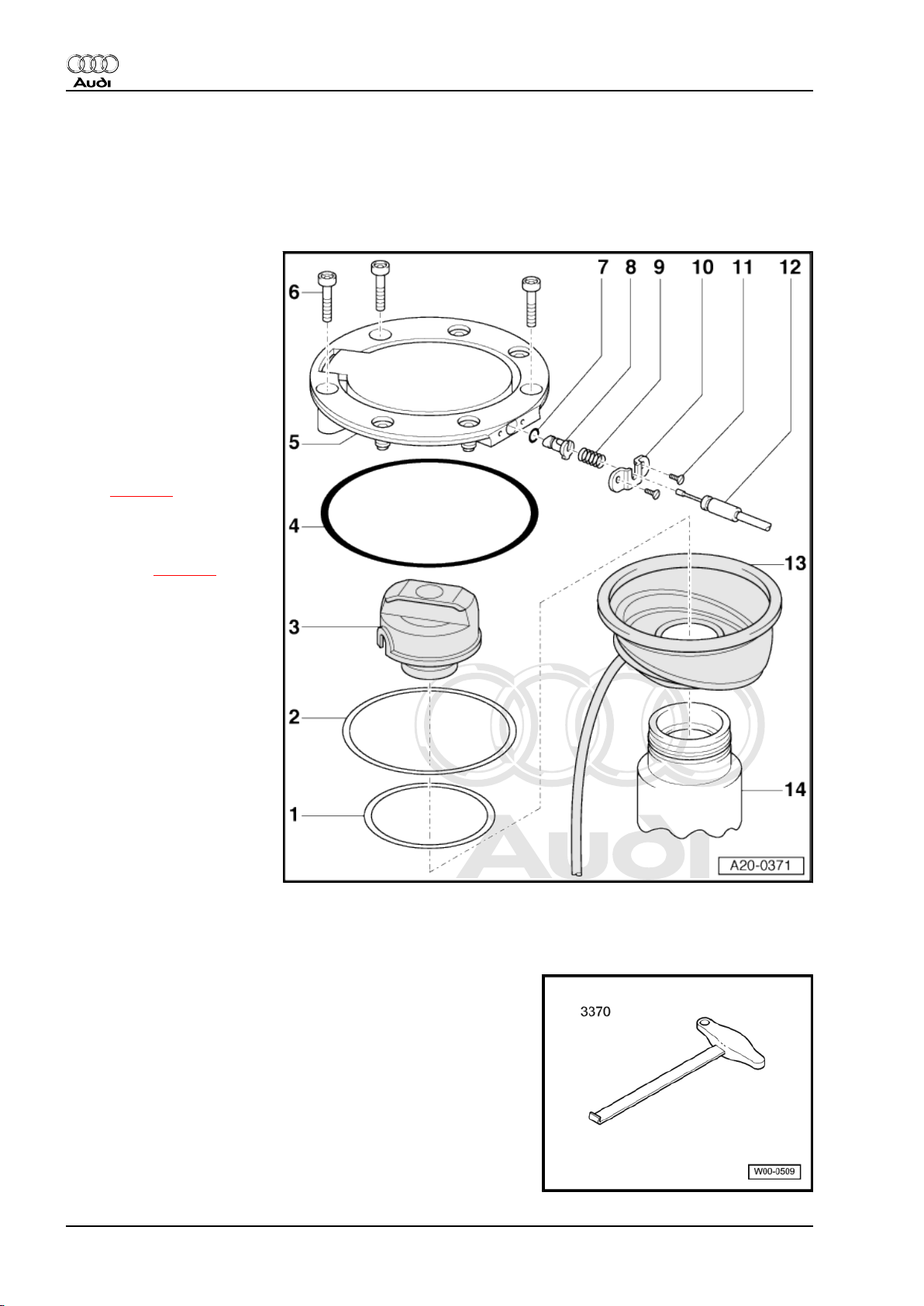
2 Tank flap - all versions
2.1 Tank flap - exploded view
1 - Retaining ring
❑ Small diameter
2 - Retaining ring
❑ Large diameter
3 - Filler cap
❑ With seal
4 - O-ring
❑ Renew if damaged
5 - Tank flap unit
❑ Removing and installing
⇒ page 4
6 - Bolt
❑ To remove tank flap, just
remove the 3 bolts illus‐
trated ⇒ page 4
❑ 4 Nm
7 - O-ring
❑ Renew if damaged
8 - Locking element
9 - Compression spring
10 - Bracket
11 - Bolt
12 - Release cable
13 - Rubber cup
❑ With overflow hose
14 - Filler neck
2.2 Removing and installing tank flap unit
Special tools and workshop equipment required
♦ Front-end hook -3370-
4 Rep. Gr.20 - Fuel supply system
Page 9
Protected by copyright. Copying for private or commercial purposes, in part or in whole, is not
permitted unless authorised by AUDI AG. AUDI AG does not guarantee or accept any liability
with respect to the correctness of information in this document. Copyright by AUDI AG.
Fuel supply system, petrol engines - Edition 06.2007
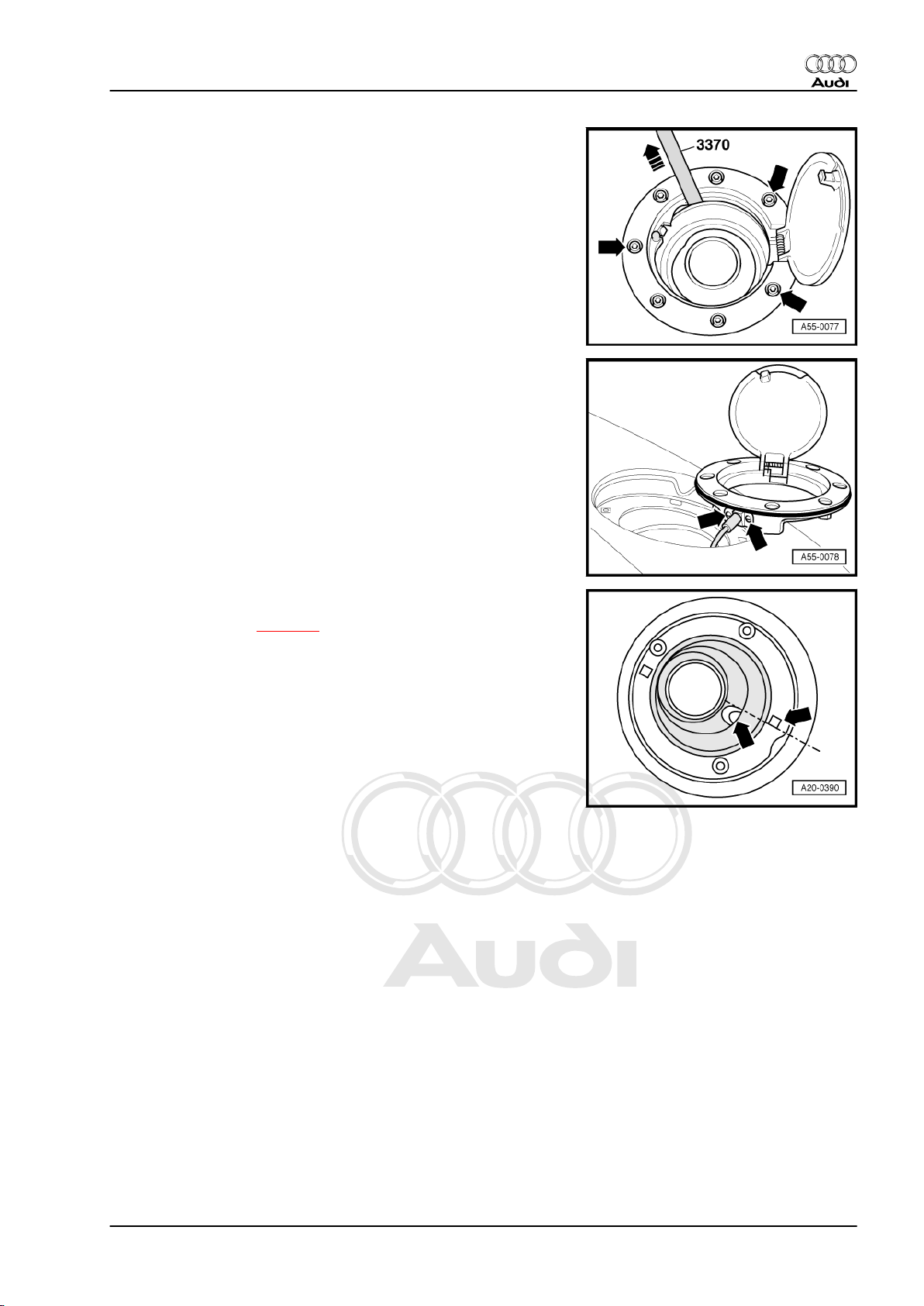
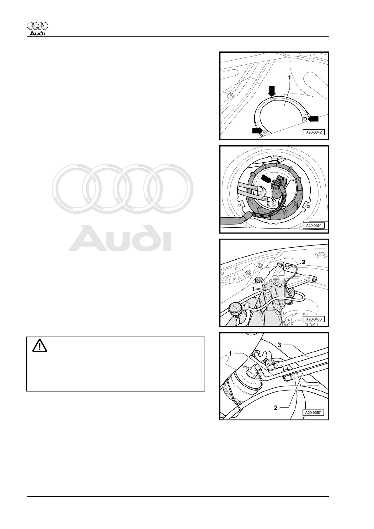
Removing
– Remove the 3 bolts marked by -arrows-.
– Lift tank flap unit out of body vertically using front-end hook
-3370- .
– Remove bolts -arrows- for release cable.
Audi TT 1999 ➤
Installing
• Tightening torque ⇒ page 4 .
Installation is carried out in the reverse order; note the following:
– To avoid kinking overflow hose, install rubber cup as follows:
• Edge of drain hole must be aligned with edge of square hole
-arrows-.
2. Tank flap - all versions 5
Page 10
Protected by copyright. Copying for private or commercial purposes, in part or in whole, is not
permitted unless authorised by AUDI AG. AUDI AG does not guarantee or accept any liability
with respect to the correctness of information in this document. Copyright by AUDI AG.
Audi TT 1999 ➤
Fuel supply system, petrol engines - Edition 06.2007
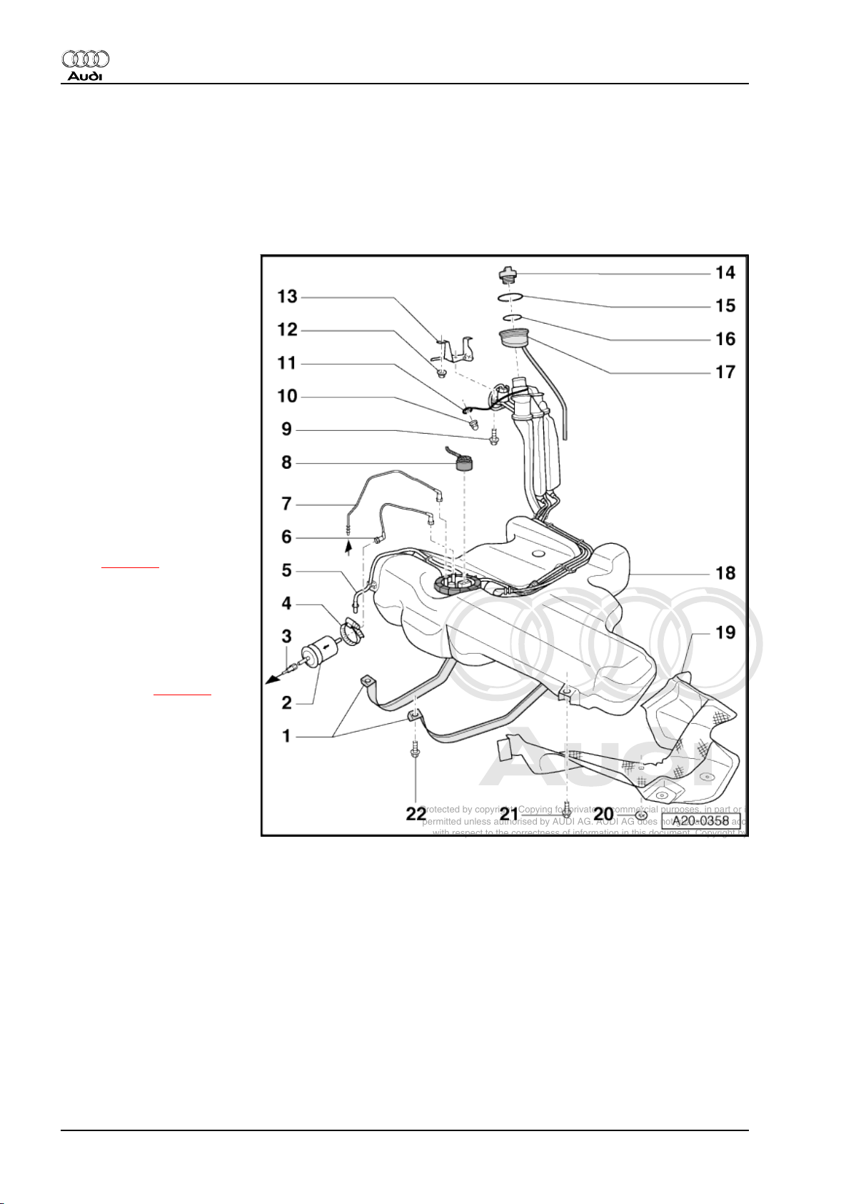
3 Fuel tank - rest-of-world vehicles
(front-wheel drive)
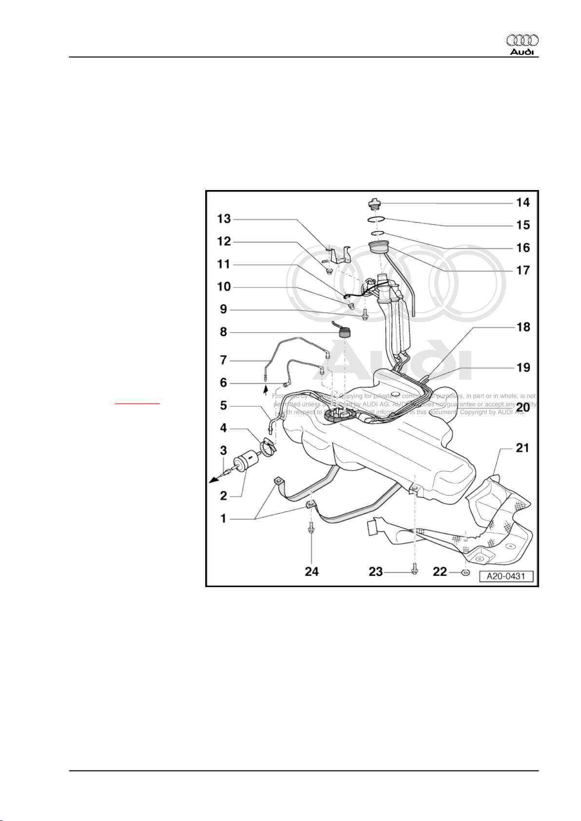
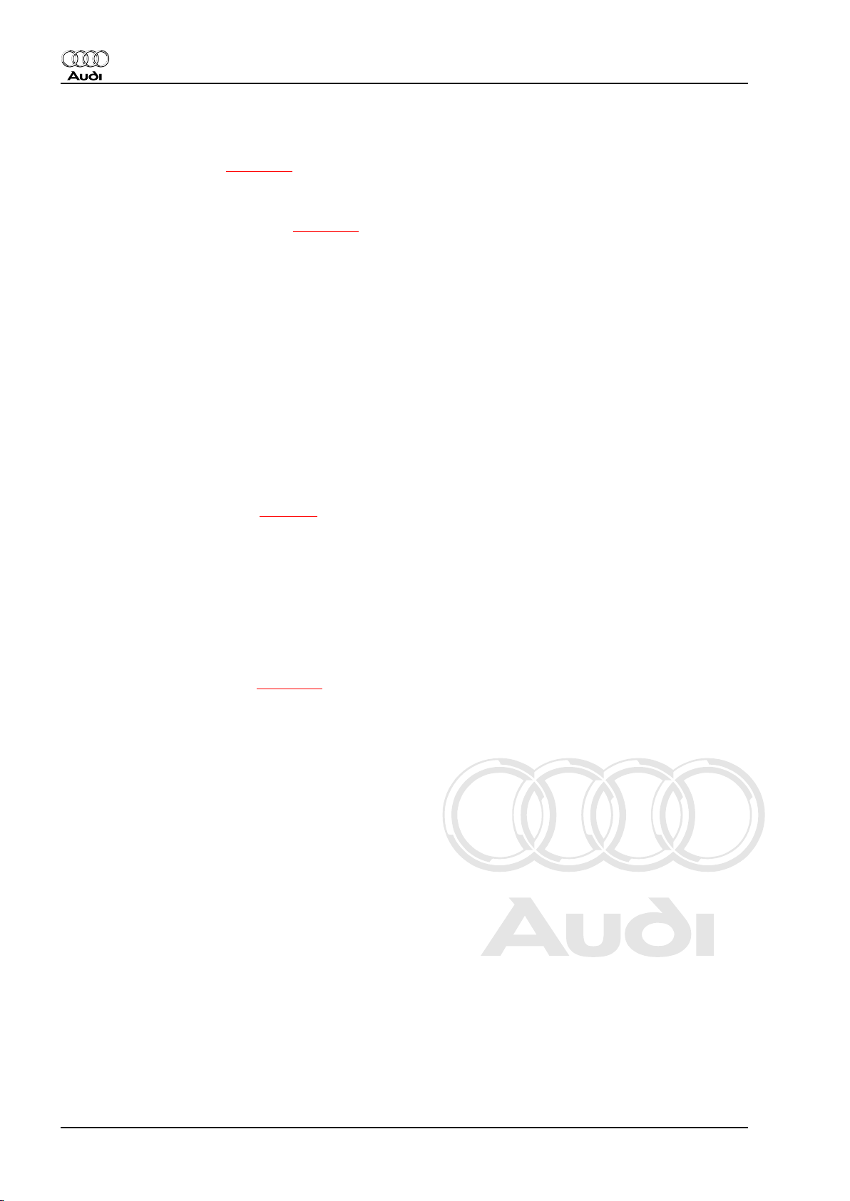
3.1 Fuel tank with attached components - exploded view
1 - Securing strap
❑ Note different lengths
2 - Fuel filter
❑ Note correct position
❑ Installation position: Ar‐
row points in throughflow direction
3 - Fuel supply pipe
❑ Black
❑ To fuel rail
❑ Press release tab on
pipe connector to dis‐
connect
4 - Retaining clamp for fuel fil‐
ter
❑ Installation position
⇒ page 8
5 - Breather pipe
❑ White
❑ From gravity valve to ac‐
tivated charcoal filter
❑ Always remove and in‐
stall together with gravi‐
ty valve ⇒ page 8
6 - Fuel supply pipe
❑ Black
❑ To fuel filter
❑ Connect to connection
“V” on flange.
❑ Press release tab on
pipe connector to dis‐
connect
7 - Fuel return pipe
❑ Blue
❑ From fuel rail
❑ Connect to connection “R” on flange.
❑ Press release tab on pipe connector to disconnect
8 - Electrical connector
❑ For fuel system pressurisation pump -G6- and fuel gauge sender -G-
9 - Bolt
❑ 11 Nm
10 - Cap nut
❑ 10 Nm
6 Rep. Gr.20 - Fuel supply system
Page 11
Protected by copyright. Copying for private or commercial purposes, in part or in whole, is not
permitted unless authorised by AUDI AG. AUDI AG does not guarantee or accept any liability
with respect to the correctness of information in this document. Copyright by AUDI AG.
Fuel supply system, petrol engines - Edition 06.2007
11 - Earth connection
❑ To eliminate electrostatic charge
❑ Installation position ⇒ page 7
❑ Ensure that connector is seated firmly on metal ring of fuel filler neck
❑ Secure contact terminal with cap nut -item 10❑ Test procedure after installing ⇒ page 8
12 - Nut
❑ 10 Nm
13 - Bracket
❑ For fuel filler neck
14 - Filler cap
❑ With seal
15 - Retaining ring
❑ Large diameter
16 - Retaining ring
❑ Small diameter
17 - Rubber cup
❑ With overflow hose
❑ Note installation position ⇒ page 5
18 - Fuel tank
❑ Removing and installing ⇒ page 10
19 - Heat shield
❑ For fuel tank
20 - Locking washer
❑ Removing: turn anti-clockwise
❑ 2 Nm
21 - Bolt
❑ 26 Nm
22 - Bolt
❑ 26 Nm
Audi TT 1999 ➤
Installation position of earth connection
– Route earth connection as shown in illustration.
– Ensure that connector -2- for earth connection is properly
seated on metal ring -1- on fuel filler neck.
– Hook earth connection into the two retainers -arrows- on fuel
filler neck.
Note
♦
For illustration purposes, the routing of the earth wire is shown
with the fuel tank removed.
♦
On some versions, only one retainer and a cable tie are fitted.
3. Fuel tank - rest-of-world vehicles (front-wheel drive) 7
Page 12
Protected by copyright. Copying for private or commercial purposes, in part or in whole, is not
permitted unless authorised by AUDI AG. AUDI AG does not guarantee or accept any liability
with respect to the correctness of information in this document. Copyright by AUDI AG.
Audi TT 1999 ➤
Fuel supply system, petrol engines - Edition 06.2007
Test procedure for earth connection
– Before securing, make sure that contact terminal -1- of wire
and cap nut -2- are free of corrosion to ensure proper earth
connection to body.
– Check that earth connection is properly secured at front re‐
tainer -arrow- on fuel filler neck.
WARNING
Risk of explosion caused by electrostatic discharge.
♦ After installation, use an ohmmeter to check the electrical
connection between the metal ring on the fuel filler neck
and a bare metal part on the body:
• Specification: approx. 0 Ω
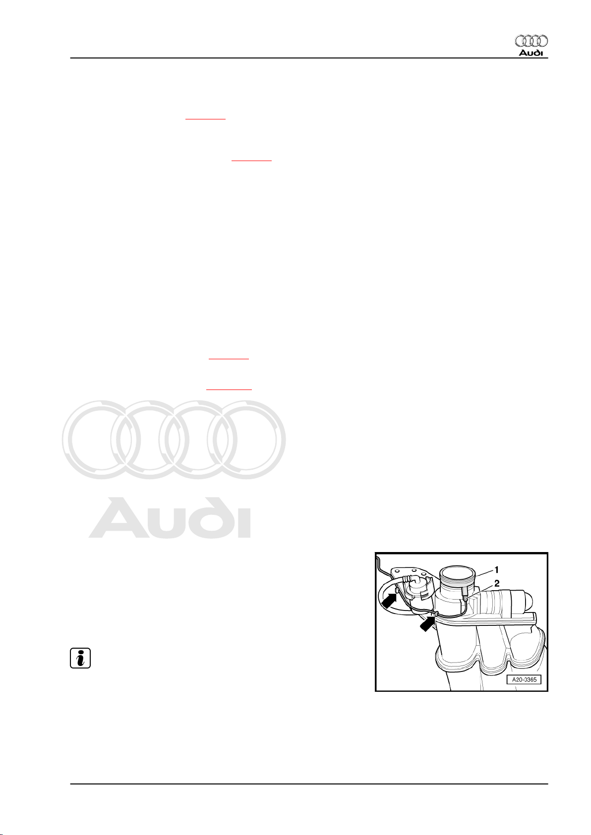
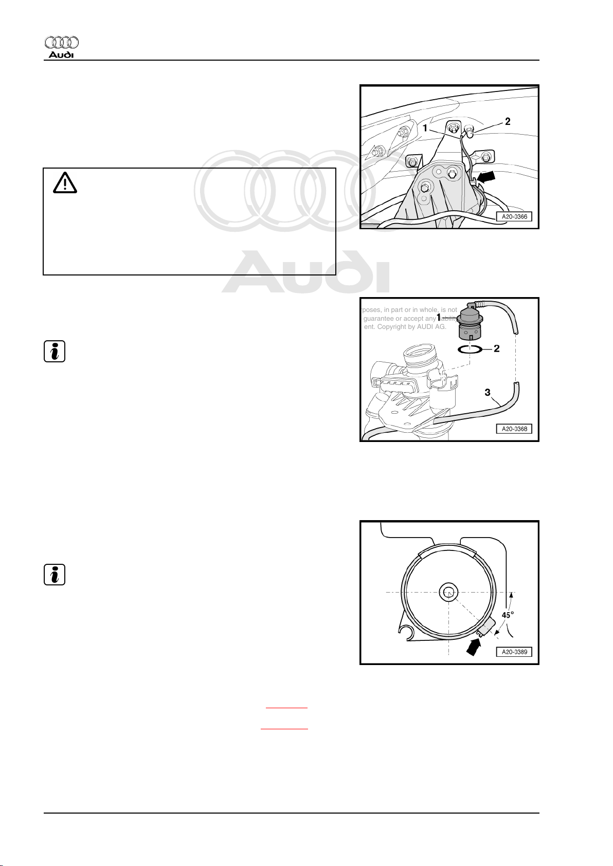
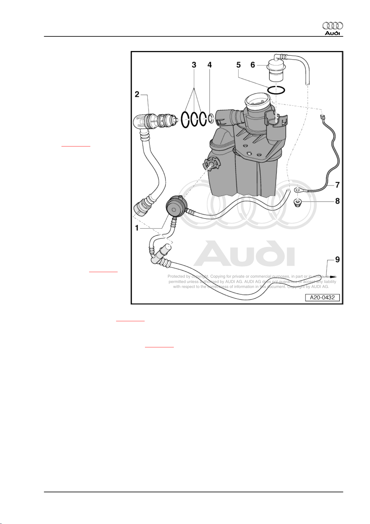
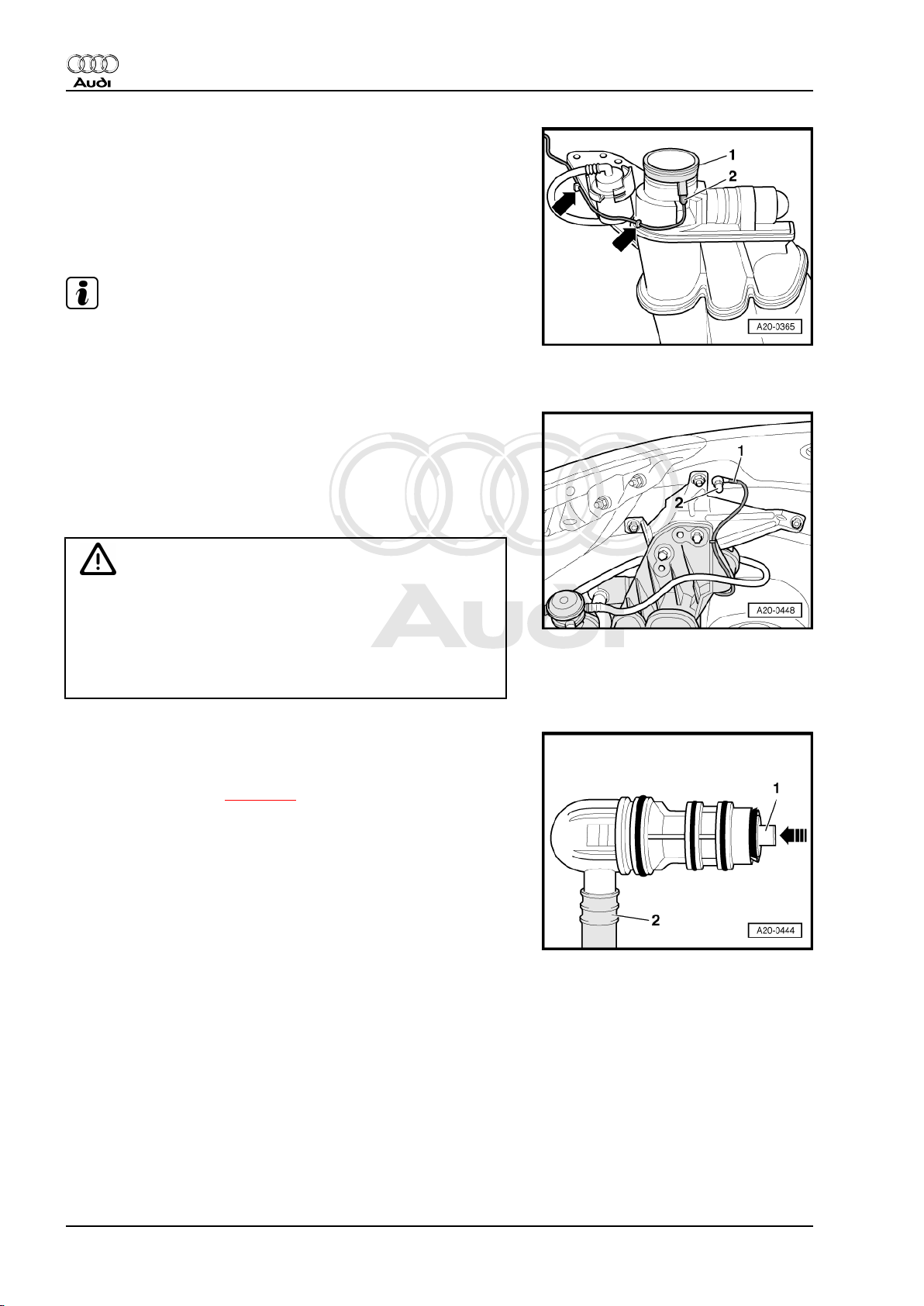
Removing, installing and checking gravity valve
Removing
Note
The gravity valve -1- can only be renewed together with breather
pipe -3-.
– Unclip gravity valve from filler neck and lift it off.
Checking
• Hold gravity valve in a vertical position: it should be possible
to blow through valve.
• Tilt gravity valve by 45°; it should not be possible to blow
through valve.
• Make sure O-ring -2- is not damaged.
Installation position of retaining clamp for fuel filter
– Position retaining clamp as illustrated -arrow-.
Note
The illustration shows the installation position from the front.
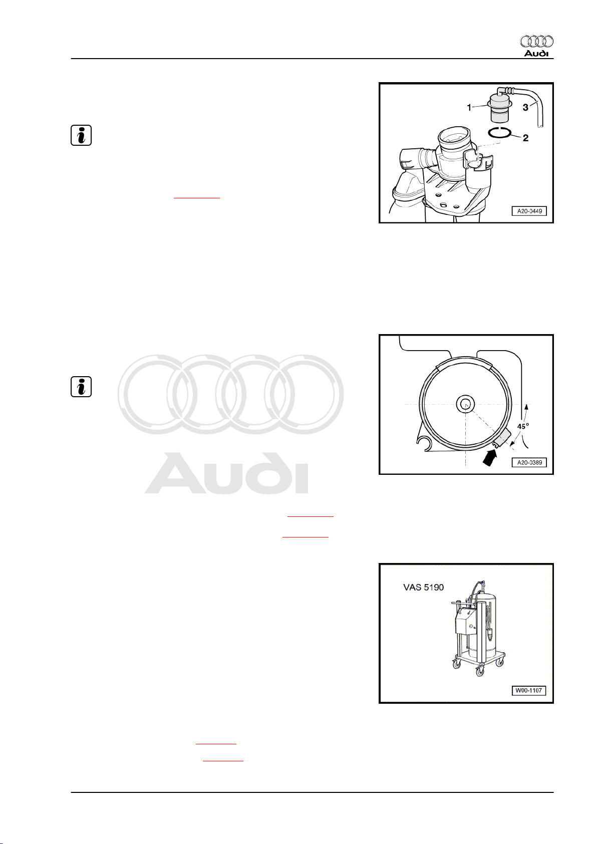
3.2 Draining fuel tank
♦
A - Procedure if fuel tank is more than 3/4 full ⇒ page 9 .
♦
B - Procedure if fuel tank is less than 3/4 full ⇒ page 10 .
Special tools and workshop equipment required
8 Rep. Gr.20 - Fuel supply system
Page 13
Protected by copyright. Copying for private or commercial purposes, in part or in whole, is not
permitted unless authorised by AUDI AG. AUDI AG does not guarantee or accept any liability
with respect to the correctness of information in this document. Copyright by AUDI AG.
Fuel supply system, petrol engines - Edition 06.2007
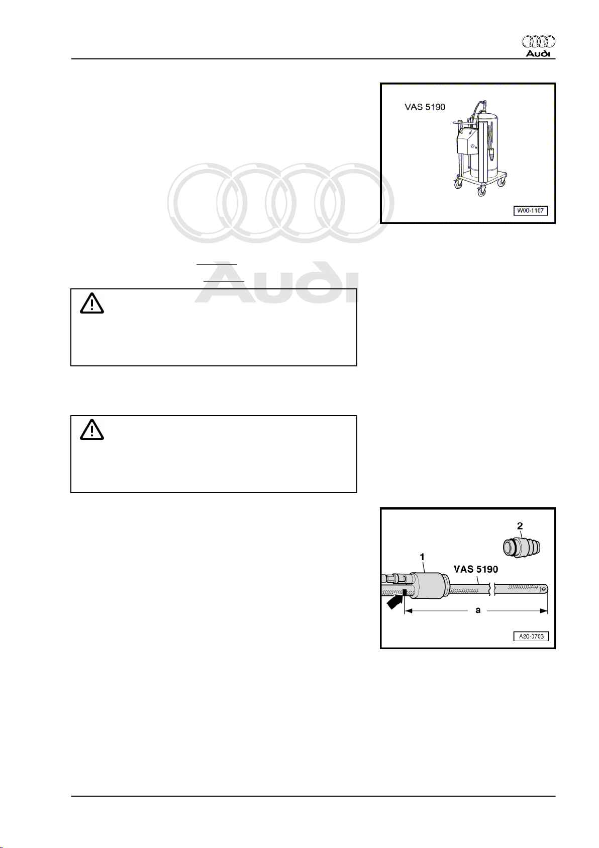
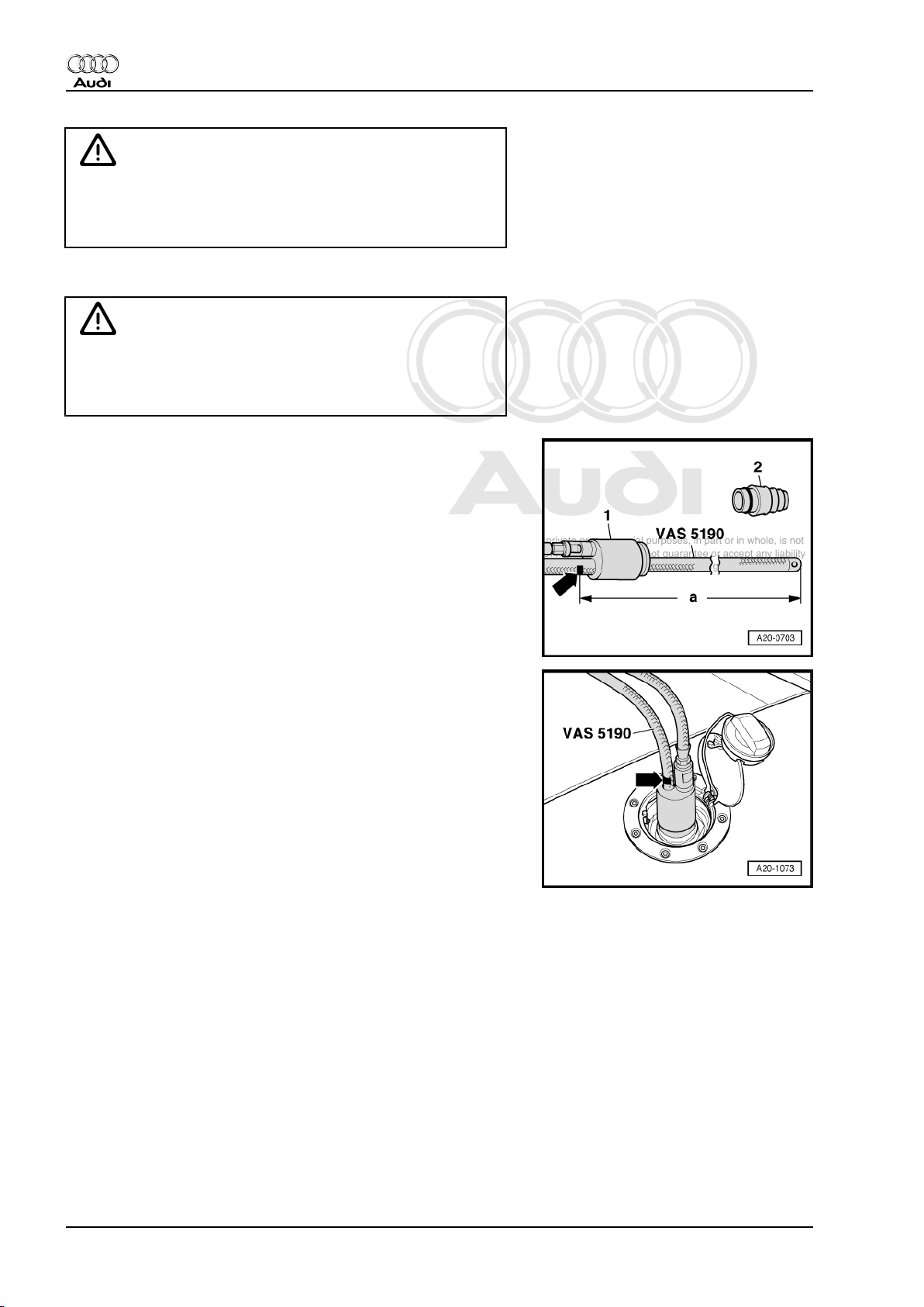
♦ Fuel extractor unit -VAS 5190-
Procedure
Observe safety precautions ⇒ page 1 .
Observe rules for cleanliness ⇒ page 2 .
Caution
To prevent damage to the electronic components when dis‐
connecting the battery:
Audi TT 1999 ➤
♦ Observe notes on procedure for disconnecting the battery.
– Disconnect battery ⇒ Rep. Gr. 27 .
– Release the tank flap.
WARNING
Risk of explosion caused by electrostatic discharge.
♦ Secure earth wire of fuel extractor unit -VAS 5190- to a
bare metal part on the body.
A - Procedure if fuel tank is more than 3/4 full
– Detach tapered adapter -2- from shaft end -1- of fuel extractor
unit -VAS 5190- .
– Use insulating tape to mark the extraction hose -arrow- at a
distance of -a- = 1045 mm from the end of the hose.
3. Fuel tank - rest-of-world vehicles (front-wheel drive) 9
Page 14
Protected by copyright. Copying for private or commercial purposes, in part or in whole, is not
permitted unless authorised by AUDI AG. AUDI AG does not guarantee or accept any liability
with respect to the correctness of information in this document. Copyright by AUDI AG.
Audi TT 1999 ➤
Fuel supply system, petrol engines - Edition 06.2007
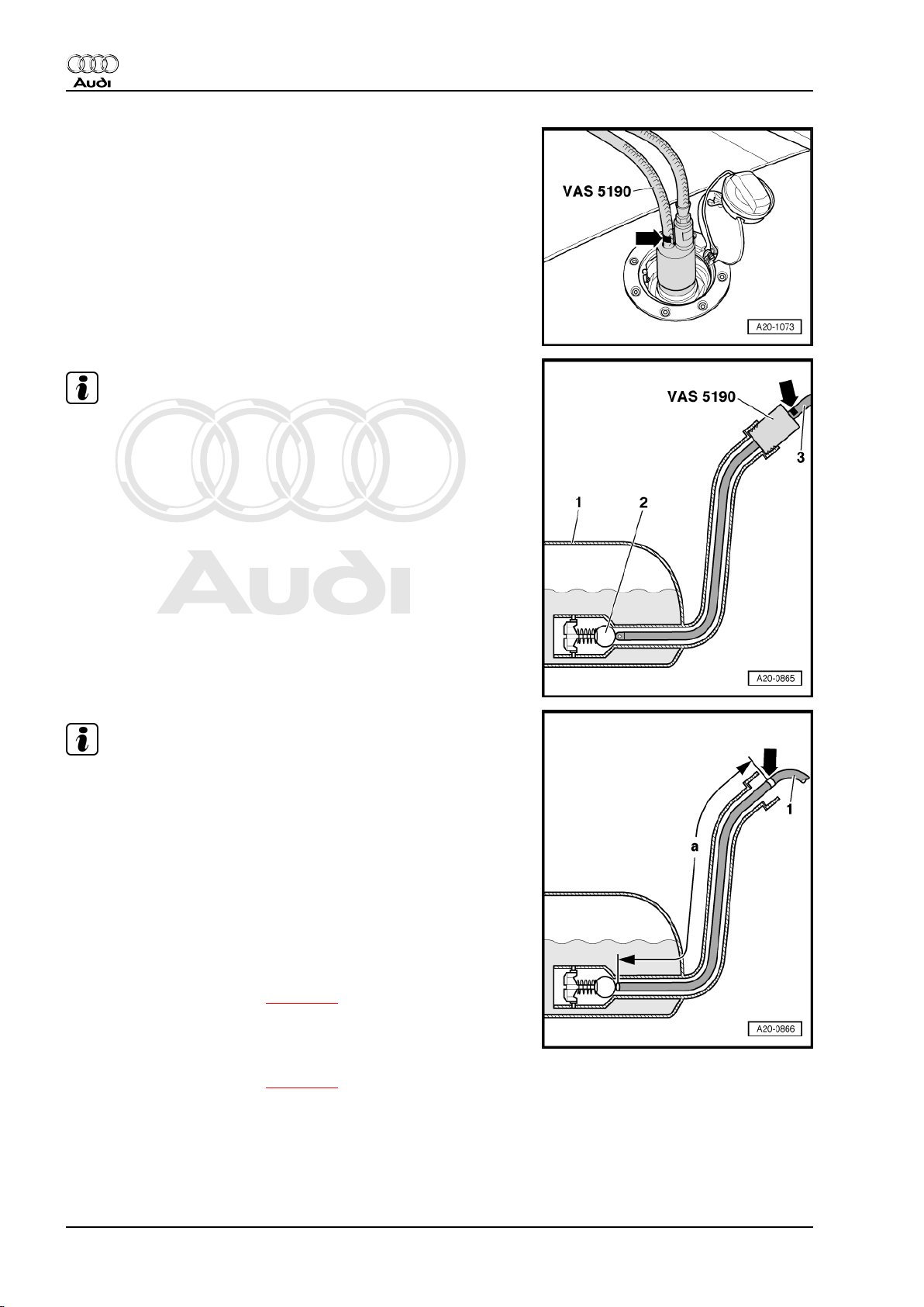
– Remove filler cap from fuel filler neck.
– Screw shaft end of fuel extractor unit -VAS 5190- onto fuel filler
neck.
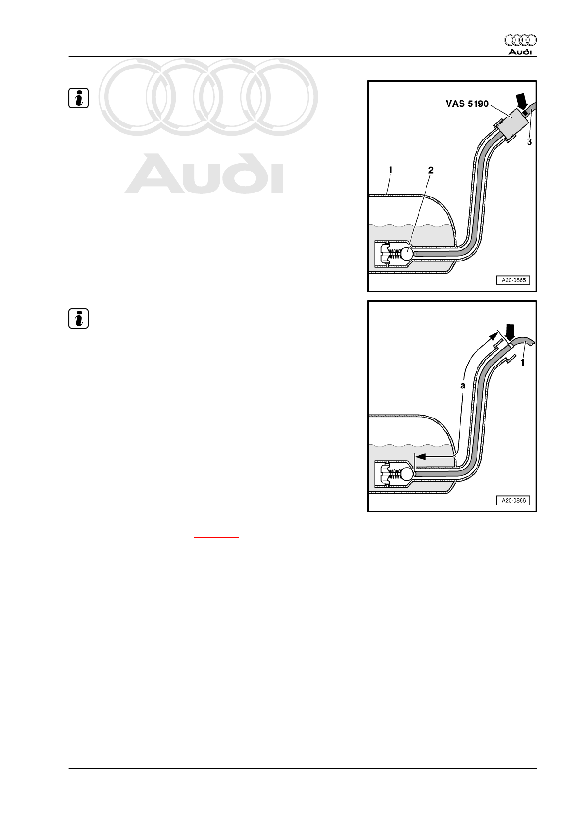
Note
A ball valve -2- is located at the bottom of the filler neck in the fuel
tank -1-; it must not be damaged by the extraction hose -3-.
– Only push extraction hose into fuel tank until marking attached
previously to hose -arrow- coincides with shaft end.
Note
♦
The procedure when using a fuel extractor without shaft end
is basically the same.
♦
In this case, make a mark -arrow- on the extraction hose at
distance -a- = 980 mm from the end of the hose using insu‐
lating tape. The extraction hose has been properly inserted
when the affixed mark is level with the edge of the filler neck.
♦
If hose is difficult to insert, apply a thin coat of engine oil. DO
NOT use silicone-based lubricant.
– Drain fuel tank as much as possible through fuel filler neck.
– Carefully remove extraction hose.
– Remove fuel delivery unit ⇒ page 31 .
– Extract remaining fuel through opening for fuel delivery unit.
B - Procedure if fuel tank is less than 3/4 full
– Remove fuel delivery unit ⇒ page 31 .
– Extract fuel through opening for fuel delivery unit.
3.3 Removing and installing fuel tank with
attached components
Special tools and workshop equipment required
10 Rep. Gr.20 - Fuel supply system
Page 15
Protected by copyright. Copying for private or commercial purposes, in part or in whole, is not
permitted unless authorised by AUDI AG. AUDI AG does not guarantee or accept any liability
with respect to the correctness of information in this document. Copyright by AUDI AG.
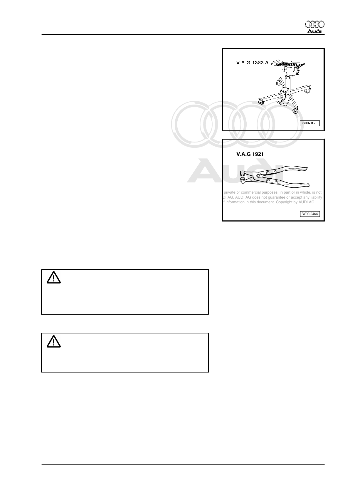
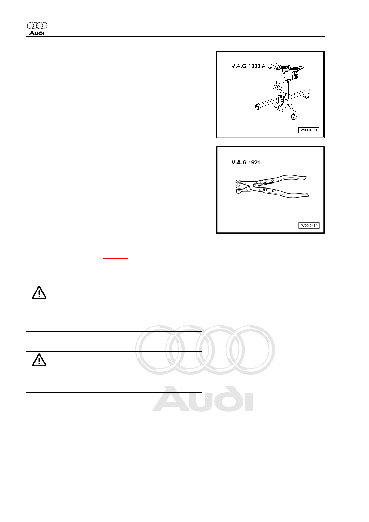
♦ Engine and gearbox jack -V.A.G 1383 A-
♦ Hose clip pliers -V.A.G 1921-
Audi TT 1999 ➤
Fuel supply system, petrol engines - Edition 06.2007
Removing
Observe safety precautions ⇒ page 1 .
Observe rules for cleanliness ⇒ page 2 .
– Release tank flap.
Caution
To prevent damage to the electronic components when dis‐
connecting the battery:
♦ Observe notes on procedure for disconnecting the battery.
– Disconnect battery ⇒ Rep. Gr. 27 .
WARNING
Risk of accident caused by weight of fuel tank
♦ Fuel tank must be empty when it is removed.
– Drain fuel tank ⇒ page 8 .
TT Coupé:
– Remove rear seat bench ⇒ Rep. Gr. 72 .
TT Roadster:
– Remove back panel side trim (right-side) ⇒ Rep. Gr. 70 .
3. Fuel tank - rest-of-world vehicles (front-wheel drive) 11
Page 16
Protected by copyright. Copying for private or commercial purposes, in part or in whole, is not
permitted unless authorised by AUDI AG. AUDI AG does not guarantee or accept any liability
with respect to the correctness of information in this document. Copyright by AUDI AG.
Audi TT 1999 ➤
Fuel supply system, petrol engines - Edition 06.2007
All vehicles (continued):
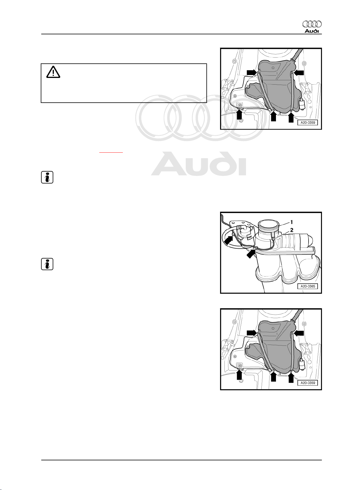
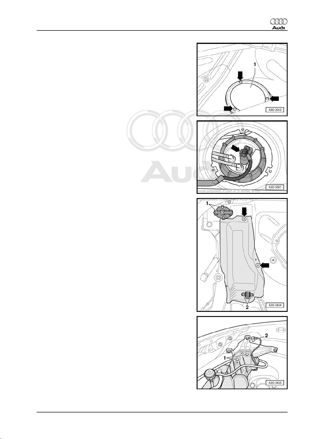
– Unscrew cover -1- for flange (right-side) -arrows-.
– Carefully release and unplug electrical connector -arrow-.
– Clean area around fuel filler neck.
– Remove filler cap from fuel filler neck.
– Remove centre and rear silencers ⇒ Rep. Gr. 26 .
– Remove rear axle ⇒ Rep. Gr. 42 .
– Remove rear right wheel housing liner ⇒ Rep. Gr. 66 .
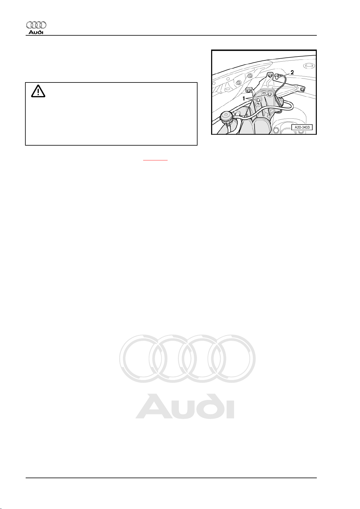
– Remove cap nut -2- for earth wire and bolts -1- for fuel filler
neck.
WARNING
Risk of injury - fuel system operates under high pressure.
♦ To reduce the pressure in the fuel system, wrap a clean
cloth around the connection and carefully loosen the con‐
nection.
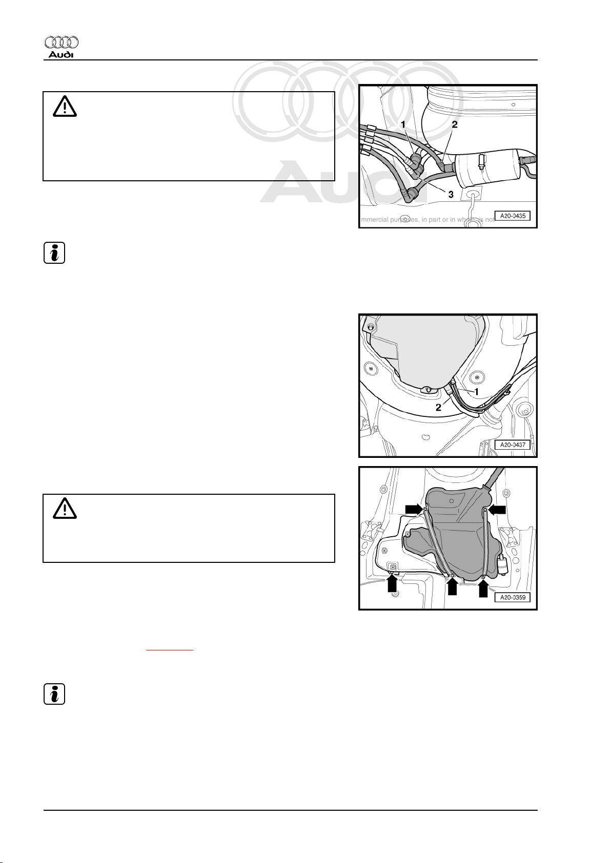
– Disconnect fuel return pipe -2- (blue), fuel supply pipe -1-
(black) and breather pipe -3- (white) from right front of fuel tank
by pressing release tabs.
12 Rep. Gr.20 - Fuel supply system
Page 17
Protected by copyright. Copying for private or commercial purposes, in part or in whole, is not
permitted unless authorised by AUDI AG. AUDI AG does not guarantee or accept any liability
with respect to the correctness of information in this document. Copyright by AUDI AG.
Fuel supply system, petrol engines - Edition 06.2007
– Position engine and gearbox jack -V.A.G 1383 A- below vehi‐
cle to support tank.
WARNING
Risk of accident caused by weight of fuel tank
♦ Fuel tank must be empty when it is removed.
– Loosen bolted connections -arrows-, starting with retaining lug
-arrow on bottom left-.
– Lower fuel tank with engine and gearbox jack -V.A.G 1383 A- .
Installing
• Tightening torques ⇒ page 6
Installation is carried out in the reverse order; note the following:
Note
Secure all hose connections with the correct type of hose clips
(same as original equipment) ⇒ Electronic parts catalogue .
Audi TT 1999 ➤
– Route earth connection as shown in illustration.
– Ensure that connector -2- for earth connection is properly
seated on metal ring -1- on fuel filler neck.
– Hook earth connection into two retainers -arrows- on fuel filler
neck.
Note
♦
For illustration purposes, the routing of the earth wire is shown
with the fuel tank removed.
♦
On some versions, only one retainer and a cable tie are fitted.
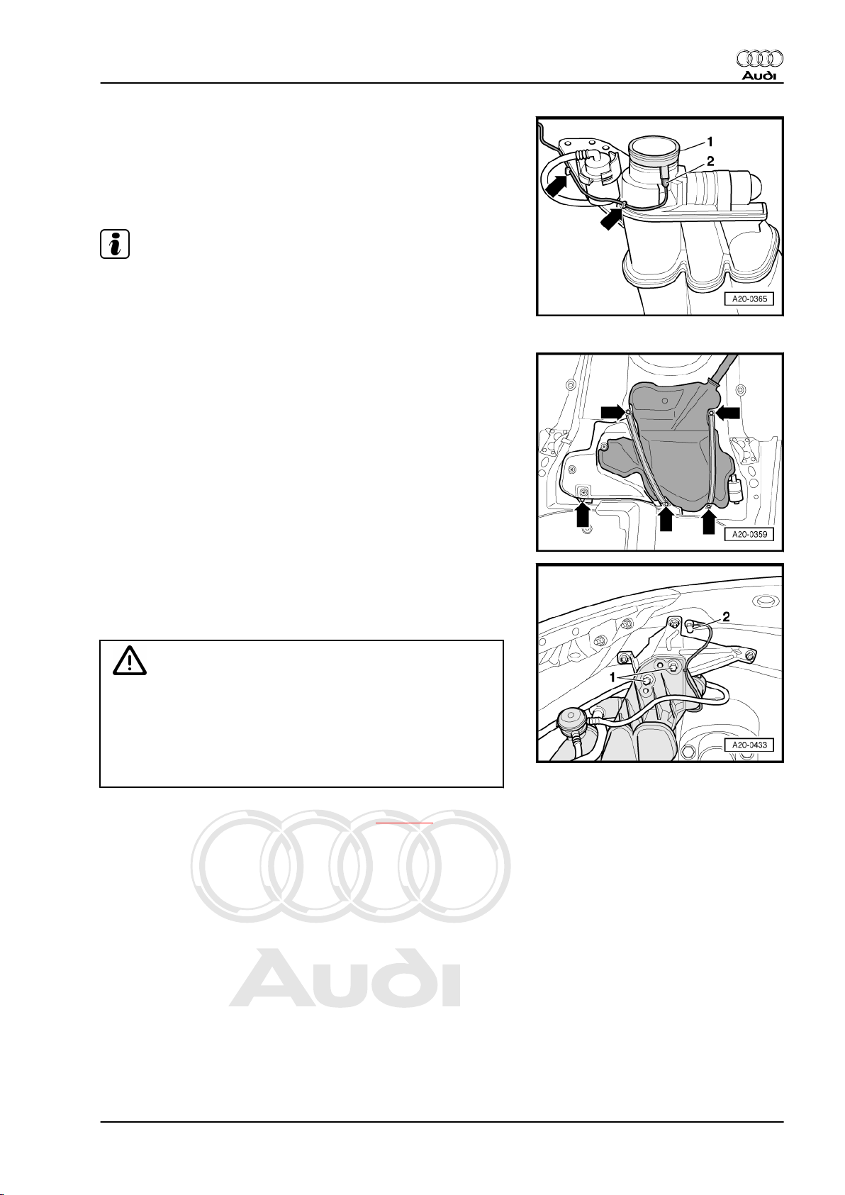
– Position fuel tank and securing straps on underside of vehicle
using engine and gearbox jack -V.A.G 1383 A- .
– Secure fuel tank at the points shown -arrows-. Tighten secur‐
ing straps first.
3. Fuel tank - rest-of-world vehicles (front-wheel drive) 13
Page 18
Protected by copyright. Copying for private or commercial purposes, in part or in whole, is not
permitted unless authorised by AUDI AG. AUDI AG does not guarantee or accept any liability
with respect to the correctness of information in this document. Copyright by AUDI AG.
Audi TT 1999 ➤
Fuel supply system, petrol engines - Edition 06.2007
– Check earth wiring at both ends for traces of oxidation and
remove oxidation if necessary.
– Tighten cap nut -2- for earth wire and bolts -1- for fuel filler
neck.
WARNING
Risk of explosion caused by electrostatic discharge.
♦ After installation, use an ohmmeter to check the electrical
connection between the metal ring on the fuel filler neck
and a bare metal part on the body:
• Specification: approx. 0 Ω
– Check installation position of rubber cup ⇒ page 5 .
– Install rear wheel housing liner ⇒ Rep. Gr. 66 .
– Install rear axle ⇒ Rep. Gr. 42 .
– Install exhaust system and align free of stress ⇒ Rep. Gr. 26 .
TT Coupé:
– Install rear seat bench ⇒ Rep. Gr. 72 .
TT Roadster:
– Install back panel side trim (right-side) ⇒ Rep. Gr. 70 .
All vehicles (continued):
– Connect battery. Observe notes on procedures required after
connecting battery ⇒ Rep. Gr. 27 .
14 Rep. Gr.20 - Fuel supply system
Page 19
Protected by copyright. Copying for private or commercial purposes, in part or in whole, is not
permitted unless authorised by AUDI AG. AUDI AG does not guarantee or accept any liability
with respect to the correctness of information in this document. Copyright by AUDI AG.
Audi TT 1999 ➤
Fuel supply system, petrol engines - Edition 06.2007
4 Fuel tank - USA vehicles (front-wheel
drive)
4.1 Fuel tank with attached components and fuel filler neck - exploded view
Fuel tank with attached components
1 - Securing strap
❑ Note different lengths
2 - Fuel filter
❑ Note correct position
❑ Installation position: Ar‐
row points in throughflow direction
3 - Fuel supply pipe
❑ Black
❑ To fuel rail
❑ Press release tab on
pipe connector to dis‐
connect
4 - Retaining clamp for fuel fil‐
ter
❑ Note installation posi‐
tion ⇒ page 19
5 - Breather pipe
❑ White
❑ From activated charcoal
filter to activated char‐
coal filter solenoid
valve 1 -N80-
6 - Fuel supply pipe
❑ Black
❑ To fuel filter
❑ Connect to connection
“V” on flange.
❑ Press release tab on
pipe connector to dis‐
connect
7 - Fuel return pipe
❑ Blue
❑ From fuel rail
❑ Connect to connection “R” on flange.
❑ Press release tab on pipe connector to disconnect
8 - Electrical connector
❑ For fuel system pressurisation pump -G6- and fuel gauge sender -G-
9 - Bolt
❑ 11 Nm
10 - Cap nut
❑ 10 Nm
4. Fuel tank - USA vehicles (front-wheel drive) 15
Page 20
Protected by copyright. Copying for private or commercial purposes, in part or in whole, is not
permitted unless authorised by AUDI AG. AUDI AG does not guarantee or accept any liability
with respect to the correctness of information in this document. Copyright by AUDI AG.
Audi TT 1999 ➤
Fuel supply system, petrol engines - Edition 06.2007
11 - Earth connection
❑ To eliminate electrostatic charge
❑ Installation position ⇒ page 18
❑ Ensure that connector is seated firmly on metal ring of fuel filler neck
❑ Secure contact terminal with cap nut -item 10❑ Test procedure after installing ⇒ page 18
12 - Nut
❑ 10 Nm
13 - Bracket
❑ For fuel filler neck
14 - Filler cap
❑ With seal
15 - Retaining ring
❑ Large diameter
16 - Retaining ring
❑ Small diameter
17 - Rubber cup
❑ With overflow hose
❑ Note installation position ⇒ page 5
18 - Breather pipe
❑ From gravity valve to activated charcoal filter
❑ Always remove and install together with gravity valve
19 - Breather pipe
❑ White
❑ From activated charcoal filter to activated charcoal filter solenoid valve 1 -N80-
20 - Fuel tank
❑ Removing and installing ⇒ page 21
21 - Heat shield
❑ For fuel tank
22 - Locking washer
❑ Removing: turn anti-clockwise
❑ 2 Nm
23 - Bolt
❑ 26 Nm
24 - Bolt
❑ 26 Nm
Filler neck
16 Rep. Gr.20 - Fuel supply system
Page 21
Protected by copyright. Copying for private or commercial purposes, in part or in whole, is not
permitted unless authorised by AUDI AG. AUDI AG does not guarantee or accept any liability
with respect to the correctness of information in this document. Copyright by AUDI AG.
Fuel supply system, petrol engines - Edition 06.2007
1 - Tank protector valve
❑ Clipped onto fuel filler
neck
❑ Closes breather pipe
when vacuum exists in
intake manifold
❑ Only remove together
with breather pipe and
gravity valve
2 - Breather valve
❑ Removing, installing
and checking
⇒ page 18
3 - O-rings
❑ Available in different
sizes
❑ Renew
4 - Seal
❑ Installation position:
sealing lip faces fuel fill‐
er neck
5 - O-ring
❑ Renew
6 - Gravity valve
❑ Only remove together
with breather pipe and
tank protector valve
❑ Checking ⇒ page 19
❑ To remove valve unclip
upwards out of filler
neck
7 - Earth connection
❑ To eliminate electrostatic charge
❑ Installation position ⇒ page 18
❑ Ensure that connector is seated firmly on metal ring of fuel filler neck
❑ Secure contact terminal with cap nut -item 8❑ Test procedure after installing ⇒ page 18
8 - Cap nut
❑ 10 Nm
9 - Breather pipe
❑ To activated charcoal filter
Audi TT 1999 ➤
4. Fuel tank - USA vehicles (front-wheel drive) 17
Page 22
Protected by copyright. Copying for private or commercial purposes, in part or in whole, is not
permitted unless authorised by AUDI AG. AUDI AG does not guarantee or accept any liability
with respect to the correctness of information in this document. Copyright by AUDI AG.
Audi TT 1999 ➤
Fuel supply system, petrol engines - Edition 06.2007
Installation position of earth connection
– Route earth connection as shown in illustration.
– Ensure that connector -2- for earth connection is properly
seated on metal ring -1- on fuel filler neck.
– Hook earth connection into the two retainers -arrows- on fuel
filler neck.
Note
♦
For illustration purposes, the routing of the earth wire is shown
with the fuel tank removed.
♦
On some versions, only one retainer and a cable tie are fitted.
Test procedure for earth connection
– Before securing, make sure that contact terminal -1- of wire
and cap nut -2- are free of corrosion to ensure proper earth
connection to body.
– Check that earth connection is properly secured at front re‐
tainer -arrow- on fuel filler neck.
WARNING
Risk of explosion caused by electrostatic discharge.
♦ After installation, use an ohmmeter to check the electrical
connection between the metal ring on the fuel filler neck
and a bare metal part on the body:
• Specification: approx. 0 Ω
Removing, installing and checking breather valve
Removing
– Removing fuel tank ⇒ page 21 .
– Unclip breather valve from side of filler neck.
– Press release tabs to detach hose connector.
Checking
– Blow into connection -2-:
• Button -1- in rest position: it should not be possible to blow
through valve.
• Button -1- pressed in direction of arrow: it should be possible
to blow through valve.
18 Rep. Gr.20 - Fuel supply system
Page 23
Protected by copyright. Copying for private or commercial purposes, in part or in whole, is not
permitted unless authorised by AUDI AG. AUDI AG does not guarantee or accept any liability
with respect to the correctness of information in this document. Copyright by AUDI AG.
Fuel supply system, petrol engines - Edition 06.2007
Removing, installing and checking gravity valve
Removing
Note
The gravity valve -1- can only be replaced together with tank pro‐
tector valve and breather pipe -3-.
– Removing fuel tank ⇒ page 21 .
– Unclip tank protector valve.
– Unclip gravity valve from filler neck and lift it off.
Checking
• Hold gravity valve in a vertical position: it should be possible
to blow through valve.
• Tilt gravity valve by 45°; it should not be possible to blow
through valve.
• Make sure O-ring -2- is not damaged.
Audi TT 1999 ➤
Installation position of retaining clamp for fuel filter
– Position retaining clamp as illustrated -arrow-.
Note
The illustration shows the installation position from the front.
4.2 Draining fuel tank
♦
♦
Special tools and workshop equipment required
♦ Fuel extractor unit -VAS 5190-
A - Procedure if fuel tank is more than 3/4 full ⇒ page 20 .
B - Procedure if fuel tank is less than 3/4 full ⇒ page 21 .
Procedure
Observe safety precautions ⇒ page 1 .
Observe rules for cleanliness ⇒ page 2 .
– Release tank flap.
4. Fuel tank - USA vehicles (front-wheel drive) 19
Page 24
Protected by copyright. Copying for private or commercial purposes, in part or in whole, is not
permitted unless authorised by AUDI AG. AUDI AG does not guarantee or accept any liability
with respect to the correctness of information in this document. Copyright by AUDI AG.
Audi TT 1999 ➤
Fuel supply system, petrol engines - Edition 06.2007
Caution
To prevent damage to the electronic components when dis‐
connecting the battery:
♦ Observe notes on procedure for disconnecting the battery.
– Disconnect battery ⇒ Rep. Gr. 27 .
WARNING
Risk of explosion caused by electrostatic discharge.
♦ Secure earth wire of fuel extractor unit -VAS 5190- to a
bare metal part on the body.
A - Procedure if fuel tank is more than 3/4 full
– Detach tapered adapter -2- from shaft end -1- of fuel extractor
unit -VAS 5190- .
– Use insulating tape to mark the extraction hose -arrow- at a
distance of -a- = 1045 mm from the end of the hose.
– Remove filler cap from fuel filler neck.
– Screw shaft end of fuel extractor unit -VAS 5190- onto fuel filler
neck.
20 Rep. Gr.20 - Fuel supply system
Page 25
Protected by copyright. Copying for private or commercial purposes, in part or in whole, is not
permitted unless authorised by AUDI AG. AUDI AG does not guarantee or accept any liability
with respect to the correctness of information in this document. Copyright by AUDI AG.
Fuel supply system, petrol engines - Edition 06.2007
Note
A ball valve -2- is located at the bottom of the filler neck in the fuel
tank -1-; it must not be damaged by the extraction hose -3-.
– Only push extraction hose into fuel tank until marking attached
previously to hose -arrow- coincides with shaft end.
Note
Audi TT 1999 ➤
♦
The procedure when using a fuel extractor without shaft end
is basically the same.
♦
In this case, make a mark -arrow- on the extraction hose at
distance -a- = 980 mm from the end of the hose using insu‐
lating tape. The extraction hose has been properly inserted
when the affixed mark is level with the edge of the filler neck.
♦
If hose is difficult to insert, apply a thin coat of engine oil. DO
NOT use silicone-based lubricant.
– Drain fuel tank as much as possible through fuel filler neck.
– Carefully remove extraction hose.
– Remove fuel delivery unit ⇒ page 31 .
– Extract remaining fuel through opening for fuel delivery unit.
B - Procedure if fuel tank is less than 3/4 full
– Remove fuel delivery unit ⇒ page 31 .
– Extract fuel through opening for fuel delivery unit.
4.3 Removing and installing fuel tank with
attached components
Special tools and workshop equipment required
4. Fuel tank - USA vehicles (front-wheel drive) 21
Page 26
Protected by copyright. Copying for private or commercial purposes, in part or in whole, is not
permitted unless authorised by AUDI AG. AUDI AG does not guarantee or accept any liability
with respect to the correctness of information in this document. Copyright by AUDI AG.
Audi TT 1999 ➤
Fuel supply system, petrol engines - Edition 06.2007
♦ Engine and gearbox jack -V.A.G 1383 A-
♦ Hose clip pliers -V.A.G 1921-
Removing
Observe safety precautions ⇒ page 1 .
Observe rules for cleanliness ⇒ page 2 .
– Release tank flap.
Caution
To prevent damage to the electronic components when dis‐
connecting the battery:
♦ Observe notes on procedure for disconnecting the battery.
– Disconnect battery ⇒ Rep. Gr. 27 .
WARNING
Risk of accident caused by weight of fuel tank
♦ Fuel tank must be empty when it is removed.
– Drain fuel tank ⇒ page 19 .
TT Coupé:
– Remove rear seat bench ⇒ Rep. Gr. 72 .
TT Roadster:
– Remove back panel side trim (right-side) ⇒ Rep. Gr. 70 .
22 Rep. Gr.20 - Fuel supply system
Page 27
Protected by copyright. Copying for private or commercial purposes, in part or in whole, is not
permitted unless authorised by AUDI AG. AUDI AG does not guarantee or accept any liability
with respect to the correctness of information in this document. Copyright by AUDI AG.
Fuel supply system, petrol engines - Edition 06.2007
All vehicles (continued):
– Unscrew cover -1- for flange (right-side) -arrows-.
– Carefully release and unplug electrical connector -arrow-.
– Clean area around fuel filler neck.
– Remove filler cap from fuel filler neck.
– Remove centre and rear silencers ⇒ Rep. Gr. 26 .
– Remove rear axle ⇒ Rep. Gr. 42 .
Audi TT 1999 ➤
– Remove bolts -1- and -2- from mountings of rear silencer.
– Remove heat shield for rear silencer -arrows-.
– Remove rear right wheel housing liner ⇒ Rep. Gr. 66 .
– Remove cap nut -2- for earth wire and bolts -1- for fuel filler
neck.
4. Fuel tank - USA vehicles (front-wheel drive) 23
Page 28
Protected by copyright. Copying for private or commercial purposes, in part or in whole, is not
permitted unless authorised by AUDI AG. AUDI AG does not guarantee or accept any liability
with respect to the correctness of information in this document. Copyright by AUDI AG.
Audi TT 1999 ➤
Fuel supply system, petrol engines - Edition 06.2007
WARNING
Risk of injury - fuel system operates under high pressure.
♦ To reduce the pressure in the fuel system, wrap a clean
cloth around the connection and carefully loosen the con‐
nection.
– Disconnect fuel return pipe -1- (blue), fuel supply pipe -2-
(black) and breather pipe -3- (white) from right front of fuel tank
by pressing release tabs.
Note
Do not detach pipe leading to fuel system diagnostic pump V144- .
– Disconnect breather pipes -1- and -2- leading to activated
charcoal filter.
– Position engine and gearbox jack -V.A.G 1383 A- below vehi‐
cle to support tank.
WARNING
Risk of accident caused by weight of fuel tank
♦ Fuel tank must be empty when it is removed.
– Loosen bolted connections -arrows-, starting with retaining lug
-arrow on bottom left-.
– Lower fuel tank with engine and gearbox jack -V.A.G 1383 A- .
Installing
• Tightening torques ⇒ page 15
Installation is carried out in the reverse order; note the following:
Note
Secure all hose connections with the correct type of hose clips
(same as original equipment) ⇒ Electronic parts catalogue .
24 Rep. Gr.20 - Fuel supply system
Page 29
Protected by copyright. Copying for private or commercial purposes, in part or in whole, is not
permitted unless authorised by AUDI AG. AUDI AG does not guarantee or accept any liability
with respect to the correctness of information in this document. Copyright by AUDI AG.
Fuel supply system, petrol engines - Edition 06.2007
– Route earth connection as shown in illustration.
– Ensure that connector -2- for earth connection is properly
seated on metal ring -1- on fuel filler neck.
– Hook earth connection into two retainers -arrows- on fuel filler
neck.
Note
♦
For illustration purposes, the routing of the earth wire is shown
with the fuel tank removed.
♦
On some versions, only one retainer and a cable tie are fitted.
– Position fuel tank and securing straps on underside of vehicle
using engine and gearbox jack -V.A.G 1383 A- .
– Secure fuel tank at the points shown -arrows-. Tighten secur‐
ing straps first.
Audi TT 1999 ➤
– Check earth wiring at both ends for traces of oxidation and
remove oxidation if necessary.
– Tighten cap nut -2- for earth wire and bolts -1- for fuel filler
neck.
WARNING
Risk of explosion caused by electrostatic discharge.
♦ After installation, use an ohmmeter to check the electrical
connection between the metal ring on the fuel filler neck
and a bare metal part on the body:
• Specification: approx. 0 Ω
– Check installation position of rubber cup ⇒ page 5 .
– Install rear wheel housing liner ⇒ Rep. Gr. 66 .
– Install rear axle ⇒ Rep. Gr. 42 .
– Install exhaust system and align free of stress ⇒ Rep. Gr. 26 .
TT Coupé:
– Install rear seat bench ⇒ Rep. Gr. 72 .
TT Roadster:
– Install back panel side trim (right-side) ⇒ Rep. Gr. 70 .
All vehicles (continued):
– Connect battery. Observe notes on procedures required after
connecting battery ⇒ Rep. Gr. 27 .
4. Fuel tank - USA vehicles (front-wheel drive) 25
Page 30
Protected by copyright. Copying for private or commercial purposes, in part or in whole, is not
permitted unless authorised by AUDI AG. AUDI AG does not guarantee or accept any liability
with respect to the correctness of information in this document. Copyright by AUDI AG.
Audi TT 1999 ➤
Fuel supply system, petrol engines - Edition 06.2007
5 Fuel delivery unit and fuel gauge
sender - all vehicles with front-wheel
drive
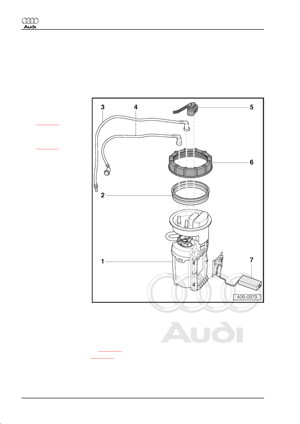
5.1 Fuel delivery unit and fuel gauge sender - exploded view
1 - Fuel delivery unit
❑ Checking fuel system
pressurisation pump G6- (electrical test)
⇒ page 27
❑ Checking residual pres‐
sure ⇒ Rep. Gr. 24
❑ Removing and installing
⇒ page 31
❑ Put at least 5 litres of
fuel into tank after instal‐
ling
2 - Seal
❑ Renew
❑ Fit dry seal in fuel tank
opening
3 - Fuel return pipe
❑ Blue
❑ From fuel rail
❑ Connect to connection
“R” on flange.
❑ Press release tab on
pipe connector to dis‐
connect
4 - Fuel supply pipe
❑ Black
❑ To fuel filter
❑ Connect to connection
“V” on flange.
❑ Press release tab on
pipe connector to dis‐
connect
5 - Electrical connector
❑ For fuel system pressurisation pump -G6- and fuel gauge sender -G-
6 - Union nut
❑ Loosen and tighten with union nut tool -3217❑ 80 Nm
7 - Fuel gauge sender -G-
❑ Checking resistance values ⇒ page 34
❑ Removing and installing ⇒ page 37
26 Rep. Gr.20 - Fuel supply system
Page 31

Protected by copyright. Copying for private or commercial purposes, in part or in whole, is not
permitted unless authorised by AUDI AG. AUDI AG does not guarantee or accept any liability
with respect to the correctness of information in this document. Copyright by AUDI AG.
Fuel supply system, petrol engines - Edition 06.2007
5.2 Fuel system pressurisation pump -G6- - electrical test
Special tools and workshop
equipment required
♦ Remote control -V.A.G
1348/3A- for V.A.G 1348
with adapter cable -V.A.G
1348/3-2-
♦ Hand-held multimeter -
V.A.G 1526C-
♦ Auxiliary measuring set -
V.A.G 1594C-
Audi TT 1999 ➤
5. Fuel delivery unit and fuel gauge sender - all vehicles with front-wheel drive 27
Page 32

Protected by copyright. Copying for private or commercial purposes, in part or in whole, is not
permitted unless authorised by AUDI AG. AUDI AG does not guarantee or accept any liability
with respect to the correctness of information in this document. Copyright by AUDI AG.
Audi TT 1999 ➤
Fuel supply system, petrol engines - Edition 06.2007
Procedure
Observe test conditions ⇒ page 2 .
– Open lid of fuse box at left side of instrument panel.
– Take out fuse in fuse holder -S228- (left row, 5th large fuse
from the top).
– Connect remote control -V.A.G 1348/3A- to right-hand termi‐
nal of fuse socket No. 28 -arrow- using adapter cable -V.A.G
1348/3-2- .
– Connect crocodile clamp to positive battery terminal “+”.
– Press remote control switch -V.A.G 1348/3A- .
• Pump should start running audibly.
Note
The fuel pump runs very quietly. Where possible, avoid noisy sur‐
roundings when testing the fuel pump.
If no noise can be heard from pump:
TT Coupé:
– Remove rear seat bench ⇒ Rep. Gr. 72 .
TT Roadster:
– Remove back panel side trim (right-side) ⇒ Rep. Gr. 70 .
All vehicles (continued):
– Unscrew cover -1- for flange (right-side) -arrows-.
– Carefully release and unplug electrical connector -arrow-.
28 Rep. Gr.20 - Fuel supply system
Page 33

Protected by copyright. Copying for private or commercial purposes, in part or in whole, is not
permitted unless authorised by AUDI AG. AUDI AG does not guarantee or accept any liability
with respect to the correctness of information in this document. Copyright by AUDI AG.
Fuel supply system, petrol engines - Edition 06.2007
– Connect multimeter between contacts -1- and -4- of electrical
connector to measure voltage.
– Press remote control switch -V.A.G 1348/3A- .
• Specification: approx. battery voltage
– If the specification is not attained, rectify open circuit ⇒ Current
flow diagrams, Electrical fault finding and Fitting locations.
– Remove fuel delivery unit if reading matches specification al‐
though no noise can be heard from pump ⇒ page 31 .
– Check that wiring between flange and fuel pump is connected
and test for continuity.
– Renew fuel delivery unit if no wiring fault is detected.
Installation is carried out in the reverse order; note the following:
– Install fuel delivery unit ⇒ page 31 , connect battery and per‐
form steps required after re-connecting battery ⇒ Rep. Gr.
27 .
Audi TT 1999 ➤
5.3 Checking fuel pump delivery rate
Special tools and workshop equipment required
♦ Remote control -V.A.G 1348/3A- for V.A.G 1348 with adapter
cable -V.A.G 1348/3-2-
5. Fuel delivery unit and fuel gauge sender - all vehicles with front-wheel drive 29
Page 34

Protected by copyright. Copying for private or commercial purposes, in part or in whole, is not
permitted unless authorised by AUDI AG. AUDI AG does not guarantee or accept any liability
with respect to the correctness of information in this document. Copyright by AUDI AG.
Audi TT 1999 ➤
Fuel supply system, petrol engines - Edition 06.2007
♦ Adapter set -V.A.G 1318/17-
♦ Fuel-resistant measuring container
Procedure
Observe test conditions ⇒ page 2 .
– Open lid of fuse box at left side of instrument panel.
– Take out fuse in fuse holder -S228- (left row, 5th large fuse
from the top).
– Connect remote control -V.A.G 1348/3A- to right-hand termi‐
nal of fuse socket No. 28 -arrow- using adapter cable -V.A.G
1348/3-2- .
– Connect crocodile clamp to positive battery terminal “+”.
– Remove filler cap from fuel filler neck.
– Unscrew bolt -1- and remove cover over coolant expansion
tank -arrow-.
30 Rep. Gr.20 - Fuel supply system
Page 35

Protected by copyright. Copying for private or commercial purposes, in part or in whole, is not
permitted unless authorised by AUDI AG. AUDI AG does not guarantee or accept any liability
with respect to the correctness of information in this document. Copyright by AUDI AG.
Fuel supply system, petrol engines - Edition 06.2007
WARNING
Risk of injury - fuel system operates under high pressure.
♦ To reduce the pressure in the fuel system, wrap a clean
cloth around the connection and carefully loosen the con‐
nection.
– Press release tab and pull return pipe -1- off pipe connec‐
tion -2-.
– Fit adapter -V.A.G 1318/17-1- onto fuel return pipe coming
from engine and hold adapter into measuring container.
– Operate remote control for 15 seconds (keep button pressed).
– Compare the quantity of fuel delivered with specification.
*
) Minimum delivery rate cm3/15 sec.
**
) Voltage at fuel pump with engine not running and pump running
(approx. 2 volts less than battery voltage).
Audi TT 1999 ➤
If minimum delivery rate is not achieved, check for the following
causes:
♦ Fuel lines have been crushed.
♦ Fuel filter is blocked.
♦ Fuel pump is defective.
5.4 Removing and installing fuel delivery
unit
Special tools and workshop equipment required
♦ Union nut tool -3217-
Removing
Observe safety precautions ⇒ page 1 .
Observe rules for cleanliness ⇒ page 2 .
Caution
To prevent damage to the electronic components when dis‐
connecting the battery:
♦ Observe notes on procedure for disconnecting the battery.
– Disconnect battery ⇒ Rep. Gr. 27 .
5. Fuel delivery unit and fuel gauge sender - all vehicles with front-wheel drive 31
Page 36

Protected by copyright. Copying for private or commercial purposes, in part or in whole, is not
permitted unless authorised by AUDI AG. AUDI AG does not guarantee or accept any liability
with respect to the correctness of information in this document. Copyright by AUDI AG.
Audi TT 1999 ➤
Fuel supply system, petrol engines - Edition 06.2007
WARNING
Large amounts of fuel can escape.
♦
The fuel tank must not be more than 1/3 full when remov‐
ing the fuel delivery unit, otherwise a large amount of fuel
will escape.
– Drain fuel tank if necessary:
♦ Rest-of-world vehicles (front-wheel drive) ⇒ page 8 .
♦ USA vehicles (front-wheel drive) ⇒ page 19 .
TT Coupé:
– Remove rear seat bench ⇒ Rep. Gr. 72 .
TT Roadster:
– Remove back panel side trim (right-side) ⇒ Rep. Gr. 70 .
All vehicles (continued):
– Unscrew cover -1- for flange (right-side) -arrows-.
– Carefully release and unplug electrical connector -arrow-.
WARNING
Risk of injury - fuel system operates under high pressure.
♦ To reduce the pressure in the fuel system, wrap a clean
cloth around the connection and carefully loosen the con‐
nection.
– Disconnect fuel supply pipe -1- and fuel return pipe -2- by
pressing release tabs.
32 Rep. Gr.20 - Fuel supply system
Page 37

Protected by copyright. Copying for private or commercial purposes, in part or in whole, is not
permitted unless authorised by AUDI AG. AUDI AG does not guarantee or accept any liability
with respect to the correctness of information in this document. Copyright by AUDI AG.
Fuel supply system, petrol engines - Edition 06.2007
WARNING
Large amounts of fuel can escape.
♦
The fuel tank must not be more than 1/3 full when remov‐
ing the fuel delivery unit, otherwise a large amount of fuel
will escape.
– Unscrew union nut using union nut tool -3217- .
– Pull fuel delivery unit and seal out of the opening in fuel tank.
Note
When removing fuel delivery unit, make sure you do not bend float
arm of fuel gauge sender -G- .
Caution
Audi TT 1999 ➤
Large amounts of fuel can escape.
♦ When handling the fuel delivery unit keep in mind that it
still contains fuel.
Installing
• Tightening torque ⇒ page 26 .
Installation is carried out in the reverse order; note the following:
Note
♦
Renew the seal.
♦
When inserting fuel delivery unit, make sure you do not bend
float arm of fuel gauge sender -G- .
♦
Make sure that fuel hoses are securely fitted.
– Insert fuel delivery unit in fuel tank.
– Install new seal for flange (seal must be installed dry).
Caution
Leakage risk
♦ The seal must not be pinched or damaged when installing
the flange.
5. Fuel delivery unit and fuel gauge sender - all vehicles with front-wheel drive 33
Page 38

Protected by copyright. Copying for private or commercial purposes, in part or in whole, is not
permitted unless authorised by AUDI AG. AUDI AG does not guarantee or accept any liability
with respect to the correctness of information in this document. Copyright by AUDI AG.
Audi TT 1999 ➤
Fuel supply system, petrol engines - Edition 06.2007
– Press flange down against spring pressure and turn flange to
installation position.
• Marking on flange must align with marking on fuel tank
-arrows-.
– Screw on union nut by hand and use union nut tool -3217- to
tighten.
– Attach fuel lines:
• Fit black supply pipe -1- onto connection marked -V-.
• Fit blue return pipe -2- onto connection marked -R-.
TT Coupé:
– Install rear seat bench ⇒ Rep. Gr. 72 .
TT Roadster:
– Install back panel side trim (right-side) ⇒ Rep. Gr. 70 .
All vehicles (continued):
– Connect battery and perform steps required after re-connect‐
ing battery ⇒ Rep. Gr. 27 .
– Put at least 5 litres of fuel into tank after installing fuel delivery
unit.
5.5 Checking fuel gauge sender -G-
Special tools and workshop equipment required
♦ Hand-held multimeter -V.A.G 1526C-
34 Rep. Gr.20 - Fuel supply system
Page 39

Protected by copyright. Copying for private or commercial purposes, in part or in whole, is not
permitted unless authorised by AUDI AG. AUDI AG does not guarantee or accept any liability
with respect to the correctness of information in this document. Copyright by AUDI AG.
Fuel supply system, petrol engines - Edition 06.2007
♦ Auxiliary measuring set -V.A.G 1594C-
Procedure
TT Coupé:
– Remove rear seat bench ⇒ Rep. Gr. 72 .
TT Roadster:
– Remove back panel side trim (right-side) ⇒ Rep. Gr. 70 .
All vehicles (continued):
– Unscrew cover -1- for flange (right-side) -arrows-.
Audi TT 1999 ➤
– Carefully release and unplug electrical connector -arrow-.
5. Fuel delivery unit and fuel gauge sender - all vehicles with front-wheel drive 35
Page 40

Protected by copyright. Copying for private or commercial purposes, in part or in whole, is not
permitted unless authorised by AUDI AG. AUDI AG does not guarantee or accept any liability
with respect to the correctness of information in this document. Copyright by AUDI AG.
Audi TT 1999 ➤
Fuel supply system, petrol engines - Edition 06.2007
Vehicles up to approx. 05.2002:
– Connect multimeter (resistance test) between contacts -2- and
-3-.
• Sender at lower stop: approx. 57 Ω.
• Sender at upper stop: approx. 290 Ω.
Note
♦
To test the maximum and minimum resistance values for “tank
full” and “tank empty”, remove the fuel delivery unit
⇒ page 31 and move the sender float all the way to its top or
bottom position.
♦
If the resistance is 0 Ω, there is a short circuit. If the resistance
is ∞ Ω, there is an open circuit in the wiring.
♦
The following values are obtained with the fuel gauge sender
-G- removed, due to the greater travel of the float arm:
Fuel gauge sender -G- removed:
• Sender at lower stop: approx. 54 Ω.
• Sender at upper stop: approx. 290 Ω.
Vehicles from approx 05.2002 onwards:
– Connect multimeter (resistance test) between contacts -2- and
-3-.
• Sender at lower stop: approx. 290 Ω.
• Sender at upper stop: approx. 57 Ω.
Note
♦
To test the maximum and minimum resistance values for “tank
full” and “tank empty”, remove the fuel delivery unit
⇒ page 31 and move the sender float all the way to its top or
bottom position.
♦
If the resistance is 0 Ω, there is a short circuit. If the resistance
is ∞ Ω, there is an open circuit in the wiring.
♦
The following values are obtained with the fuel gauge sender
-G- removed, due to the greater travel of the float arm:
Fuel gauge sender -G- removed:
• Sender at lower stop: approx. 290 Ω.
• Sender at upper stop: approx. 54 Ω.
Installation is carried out in the reverse order; note the following:
TT Coupé:
– Install rear seat bench ⇒ Rep. Gr. 72 .
TT Roadster:
– Install back panel side trim (right-side) ⇒ Rep. Gr. 70 .
36 Rep. Gr.20 - Fuel supply system
Page 41

Protected by copyright. Copying for private or commercial purposes, in part or in whole, is not
permitted unless authorised by AUDI AG. AUDI AG does not guarantee or accept any liability
with respect to the correctness of information in this document. Copyright by AUDI AG.
Fuel supply system, petrol engines - Edition 06.2007
5.6 Removing and installing fuel gauge
sender -G-
Removing
Observe safety precautions ⇒ page 1 .
Observe rules for cleanliness ⇒ page 2 .
– Remove fuel delivery unit ⇒ page 31 .
Caution
Risk of damage.
♦ First release retainer tabs on connector contact before
detaching electrical connectors on fuel gauge sender -G- .
– Release connector tabs on wires -3- and-4- and pull off.
– Lift retaining lugs -1- and -2- with a screwdriver and pull fuel
gauge sender -G- off downwards -arrow-.
Installing
Installation is carried out in the reverse order; note the following:
– Insert fuel gauge sender -G- into guides on fuel delivery unit
and press upwards until sender clicks into place.
– Plug in electrical connectors and check that they have engag‐
ed properly.
– Install fuel delivery unit ⇒ page 31 , connect battery and per‐
form steps required after re-connecting battery ⇒ Rep. Gr.
27 .
Audi TT 1999 ➤
5. Fuel delivery unit and fuel gauge sender - all vehicles with front-wheel drive 37
Page 42

Protected by copyright. Copying for private or commercial purposes, in part or in whole, is not
permitted unless authorised by AUDI AG. AUDI AG does not guarantee or accept any liability
with respect to the correctness of information in this document. Copyright by AUDI AG.
Audi TT 1999 ➤
Fuel supply system, petrol engines - Edition 06.2007
6 Fuel tank - rest-of-world vehicles
(four-wheel drive)
6.1 Fuel tank with attached components - exploded view
1 - Heat shield
❑ For fuel tank
❑ With support bracket
2 - Fuel filter
❑ Note correct position
❑ Installation position: Ar‐
row points in throughflow direction
3 - Fuel supply pipe
❑ Black
❑ To fuel rail
❑ Press release tab on
pipe connector to dis‐
connect
4 - Retaining clamp for fuel fil‐
ter
❑ Installation position
⇒ page 40
5 - Breather pipe
❑ White
❑ From gravity valve to ac‐
tivated charcoal filter
❑ Always remove and in‐
stall together with gravi‐
ty valve ⇒ page 40
6 - Fuel supply pipe
❑ Black
❑ To fuel filter
❑ Connect to connection
“V” on flange.
❑ Press release tab on
pipe connector to dis‐
connect
7 - Fuel return pipe
❑ Blue
❑ From fuel rail
❑ Connect to connection “R” on flange.
❑ Press release tab on pipe connector to disconnect
8 - Electrical connector
❑ For fuel system pressurisation pump -G6- , fuel gauge sender -G- and fuel gauge sender 2 -G169-
9 - Bolt
❑ 11 Nm
10 - Cap nut
❑ 10 Nm
38 Rep. Gr.20 - Fuel supply system
Page 43

Protected by copyright. Copying for private or commercial purposes, in part or in whole, is not
permitted unless authorised by AUDI AG. AUDI AG does not guarantee or accept any liability
with respect to the correctness of information in this document. Copyright by AUDI AG.
Fuel supply system, petrol engines - Edition 06.2007
11 - Earth connection
❑ To eliminate electrostatic charge
❑ Installation position ⇒ page 39
❑ Ensure that connector is seated firmly on metal ring of fuel filler neck
❑ Secure contact terminal with cap nut -item 10❑ Test procedure after installing ⇒ page 40
12 - Nut
❑ 10 Nm
13 - Bracket
❑ For fuel filler neck
14 - Filler cap
❑ With seal
15 - Retaining ring
❑ Large diameter
16 - Retaining ring
❑ Small diameter
17 - Rubber cup
❑ With overflow hose
❑ Note installation position ⇒ page 5
18 - Fuel tank
❑ Removing and installing ⇒ page 43
19 - Bolt
❑ 26 Nm
20 - Securing strap
❑ Note different lengths
21 - Bolt
❑ 26 Nm
22 - Locking washer
❑ Removing: turn anti-clockwise
❑ 2 Nm
23 - Nut
❑ 26 Nm
Audi TT 1999 ➤
Installation position of earth connection
– Route earth connection as shown in illustration.
– Ensure that connector -2- for earth connection is properly
seated on metal ring -1- on fuel filler neck.
– Hook earth connection into the two retainers -arrows- on fuel
filler neck.
Note
♦
For illustration purposes, the routing of the earth wire is shown
with the fuel tank removed.
♦
On some versions, only one retainer and a cable tie are fitted.
6. Fuel tank - rest-of-world vehicles (four-wheel drive) 39
Page 44

Protected by copyright. Copying for private or commercial purposes, in part or in whole, is not
permitted unless authorised by AUDI AG. AUDI AG does not guarantee or accept any liability
with respect to the correctness of information in this document. Copyright by AUDI AG.
Audi TT 1999 ➤
Fuel supply system, petrol engines - Edition 06.2007
Test procedure for earth connection
– Before securing, make sure that contact terminal -1- of wire
and cap nut -2- are free of corrosion to ensure proper earth
connection to body.
– Check that earth connection is properly secured at front re‐
tainer -arrow- on fuel filler neck.
WARNING
Risk of explosion caused by electrostatic discharge.
♦ After installation, use an ohmmeter to check the electrical
connection between the metal ring on the fuel filler neck
and a bare metal part on the body:
• Specification: approx. 0 Ω
Removing, installing and checking gravity valve
Removing
Note
The gravity valve -1- can only be renewed together with breather
pipe -3-.
– Unclip gravity valve from filler neck and lift it off.
Checking
• Hold gravity valve in a vertical position: it should be possible
to blow through valve.
• Tilt gravity valve by 45°; it should not be possible to blow
through valve.
• Make sure O-ring -2- is not damaged.
Installation position of retaining clamp for fuel filter
– Position retaining clamp as illustrated -arrow-.
Note
The illustration shows the installation position from the front.
6.2 Draining fuel tank
♦
A - Procedure if fuel tank is more than 3/4 full ⇒ page 41 .
♦
B - Procedure if fuel tank is less than 3/4 full ⇒ page 42 .
Special tools and workshop equipment required
40 Rep. Gr.20 - Fuel supply system
Page 45

Protected by copyright. Copying for private or commercial purposes, in part or in whole, is not
permitted unless authorised by AUDI AG. AUDI AG does not guarantee or accept any liability
with respect to the correctness of information in this document. Copyright by AUDI AG.
♦ Fuel extractor unit -VAS 5190-
Procedure
Observe safety precautions ⇒ page 1 .
Observe rules for cleanliness ⇒ page 2 .
– Release tank flap.
Caution
Audi TT 1999 ➤
Fuel supply system, petrol engines - Edition 06.2007
To prevent damage to the electronic components when dis‐
connecting the battery:
♦ Observe notes on procedure for disconnecting the battery.
– Disconnect battery ⇒ Rep. Gr. 27 .
WARNING
Risk of explosion caused by electrostatic discharge.
♦ Secure earth wire of fuel extractor unit -VAS 5190- to a
bare metal part on the body.
A - Procedure if fuel tank is more than 3/4 full
– Detach tapered adapter -2- from shaft end -1- of fuel extractor
unit -VAS 5190- .
– Use insulating tape to mark the extraction hose -arrow- at a
distance of -a- = 1415 mm from the end of the hose.
6. Fuel tank - rest-of-world vehicles (four-wheel drive) 41
Page 46

Protected by copyright. Copying for private or commercial purposes, in part or in whole, is not
permitted unless authorised by AUDI AG. AUDI AG does not guarantee or accept any liability
with respect to the correctness of information in this document. Copyright by AUDI AG.
Audi TT 1999 ➤
Fuel supply system, petrol engines - Edition 06.2007
– Remove filler cap from fuel filler neck.
– Screw shaft end of fuel extractor unit -VAS 5190- onto fuel filler
neck.
Note
A ball valve -2- is located at the bottom of the filler neck in the fuel
tank -1-; it must not be damaged by the extraction hose -3-.
– Only push extraction hose into fuel tank until marking attached
previously to hose -arrow- coincides with shaft end.
Note
♦
The procedure when using a fuel extractor without shaft end
is basically the same.
♦
In this case, make a mark -arrow- on the extraction hose at
distance -a- = 1350 mm from the end of the hose using insu‐
lating tape. The extraction hose has been properly inserted
when the affixed mark is level with the edge of the filler neck.
♦
If hose is difficult to insert, apply a thin coat of engine oil. DO
NOT use silicone-based lubricant.
– Drain fuel tank as much as possible through fuel filler neck.
– Carefully remove extraction hose.
– Remove fuel delivery unit ⇒ page 64 .
– Extract remaining fuel through opening for fuel delivery unit.
B - Procedure if fuel tank is less than 3/4 full
– Remove fuel delivery unit ⇒ page 64 .
– Extract remaining fuel from right chamber of fuel tank through
opening for fuel delivery unit.
– Push hose into left chamber of fuel tank and extract remaining
fuel.
42 Rep. Gr.20 - Fuel supply system
Page 47

Protected by copyright. Copying for private or commercial purposes, in part or in whole, is not
permitted unless authorised by AUDI AG. AUDI AG does not guarantee or accept any liability
with respect to the correctness of information in this document. Copyright by AUDI AG.
Fuel supply system, petrol engines - Edition 06.2007
6.3 Removing and installing fuel tank with attached components
Special tools and workshop equipment required
♦ Engine and gearbox jack -V.A.G 1383 A-
♦ Hose clip pliers -V.A.G 1921-
Audi TT 1999 ➤
Removing
Observe safety precautions ⇒ page 1 .
Observe rules for cleanliness ⇒ page 2 .
– Release tank flap.
Caution
To prevent damage to the electronic components when dis‐
connecting the battery:
♦ Observe notes on procedure for disconnecting the battery.
– Disconnect battery ⇒ Rep. Gr. 27 .
WARNING
Risk of accident caused by weight of fuel tank
♦ Fuel tank must be empty when it is removed.
– Drain fuel tank ⇒ page 40 .
TT Coupé:
– Remove rear seat bench ⇒ Rep. Gr. 72 .
TT Roadster:
– Remove back panel side trim (right-side) ⇒ Rep. Gr. 70 .
6. Fuel tank - rest-of-world vehicles (four-wheel drive) 43
Page 48

Protected by copyright. Copying for private or commercial purposes, in part or in whole, is not
permitted unless authorised by AUDI AG. AUDI AG does not guarantee or accept any liability
with respect to the correctness of information in this document. Copyright by AUDI AG.
Audi TT 1999 ➤
Fuel supply system, petrol engines - Edition 06.2007
All vehicles (continued):
– Unscrew cover -1- for flange (right-side) -arrows-.
– Carefully release and unplug electrical connector -arrow-.
– Clean area around fuel filler neck.
– Remove filler cap from fuel filler neck.
– Remove centre and rear silencers ⇒ Rep. Gr. 26 .
– Remove propshaft ⇒ Rear final drive 02D; Rep. Gr. 39 .
– Remove rear axle ⇒ Rep. Gr. 42 .
– Remove rear right wheel housing liner ⇒ Rep. Gr. 66 .
– Remove cap nut -2- for earth wire and bolts -1- for fuel filler
neck.
WARNING
Risk of injury - fuel system operates under high pressure.
♦ To reduce the pressure in the fuel system, wrap a clean
cloth around the connection and carefully loosen the con‐
nection.
– Disconnect fuel return pipe -2- (blue), fuel supply pipe -1-
(black) and breather pipe -3- (white) from right front of fuel tank
by pressing release tabs.
44 Rep. Gr.20 - Fuel supply system
Page 49

Protected by copyright. Copying for private or commercial purposes, in part or in whole, is not
permitted unless authorised by AUDI AG. AUDI AG does not guarantee or accept any liability
with respect to the correctness of information in this document. Copyright by AUDI AG.
Fuel supply system, petrol engines - Edition 06.2007
– Position engine and gearbox jack -V.A.G 1383 A- below vehi‐
cle to support tank.
WARNING
Risk of accident caused by weight of fuel tank
♦ Fuel tank must be empty when it is removed.
– Slacken bolted connections in the following order:
♦ -1- and -5- for retaining lugs
♦ -3- and -7- for support bracket
♦ -2, 4, 6, 8- for securing straps.
– Lower fuel tank with engine and gearbox jack -V.A.G 1383 A- .
Installing
• Tightening torques ⇒ page 38
Installation is carried out in the reverse order; note the following:
Audi TT 1999 ➤
Note
Secure all hose connections with the correct type of hose clips
(same as original equipment) ⇒ Electronic parts catalogue .
– Route earth connection as shown in illustration.
– Ensure that connector -2- for earth connection is properly
seated on metal ring -1- on fuel filler neck.
– Hook earth connection into two retainers -arrows- on fuel filler
neck.
Note
♦
For illustration purposes, the routing of the earth wire is shown
with the fuel tank removed.
♦
On some versions, only one retainer and a cable tie are fitted.
– Position the fuel tank with securing straps and brackets on
underbody, using engine and gearbox jack -V.A.G 1383 A- .
– Tighten bolts as follows:
♦ -2, 4, 6, 8- for securing straps.
♦ -3- and -7- for support bracket
♦ -1- and -5- for retaining lugs
6. Fuel tank - rest-of-world vehicles (four-wheel drive) 45
Page 50

Protected by copyright. Copying for private or commercial purposes, in part or in whole, is not
permitted unless authorised by AUDI AG. AUDI AG does not guarantee or accept any liability
with respect to the correctness of information in this document. Copyright by AUDI AG.
Audi TT 1999 ➤
Fuel supply system, petrol engines - Edition 06.2007
– Check earth wiring at both ends for traces of oxidation and
remove oxidation if necessary.
– Tighten cap nut -2- for earth wire and bolts -1- for fuel filler
neck.
WARNING
Risk of explosion caused by electrostatic discharge.
♦ After installation, use an ohmmeter to check the electrical
connection between the metal ring on the fuel filler neck
and a bare metal part on the body:
• Specification: approx. 0 Ω
– Check installation position of rubber cup ⇒ page 5 .
– Install rear wheel housing liner ⇒ Rep. Gr. 66 .
– Install rear axle ⇒ Rep. Gr. 42 .
– Install propshaft ⇒ Rear final drive 02D; Rep. Gr. 39 .
– Install exhaust system and align free of stress ⇒ Rep. Gr. 26 .
TT Coupé:
– Install rear seat bench ⇒ Rep. Gr. 72 .
TT Roadster:
– Install back panel side trim (right-side) ⇒ Rep. Gr. 70 .
All vehicles (continued):
– Connect battery. Observe notes on procedures required after
connecting battery ⇒ Rep. Gr. 27 .
46 Rep. Gr.20 - Fuel supply system
Page 51

Protected by copyright. Copying for private or commercial purposes, in part or in whole, is not
permitted unless authorised by AUDI AG. AUDI AG does not guarantee or accept any liability
with respect to the correctness of information in this document. Copyright by AUDI AG.
Audi TT 1999 ➤
Fuel supply system, petrol engines - Edition 06.2007
7 Fuel tank - USA vehicles (four-wheel
drive)
7.1 Fuel tank with attached components and fuel filler neck - exploded view
Fuel tank with attached components
1 - Heat shield
❑ For fuel tank
2 - Fuel filter
❑ Note correct position
❑ Installation position: Ar‐
row points in throughflow direction
3 - Fuel supply pipe
❑ Black
❑ To fuel rail
❑ Press release tab on
pipe connector to dis‐
connect
4 - Retaining clamp for fuel fil‐
ter
❑ Installation position
⇒ page 51
5 - Breather pipe
❑ White
❑ From activated charcoal
filter to activated char‐
coal filter solenoid
valve 1 -N80-
6 - Fuel supply pipe
❑ Black
❑ To fuel filter
❑ Connect to connection
“V” on flange.
❑ Press release tab on
pipe connector to dis‐
connect
7 - Fuel return pipe
❑ Blue
❑ From fuel rail
❑ Connect to connection “R” on flange.
❑ Press release tab on pipe connector to disconnect
8 - Electrical connector
❑ For fuel system pressurisation pump -G6- , fuel gauge sender -G- and fuel gauge sender 2 -G169-
9 - Bolt
❑ 11 Nm
10 - Cap nut
❑ 10 Nm
7. Fuel tank - USA vehicles (four-wheel drive) 47
Page 52

Protected by copyright. Copying for private or commercial purposes, in part or in whole, is not
permitted unless authorised by AUDI AG. AUDI AG does not guarantee or accept any liability
with respect to the correctness of information in this document. Copyright by AUDI AG.
Audi TT 1999 ➤
Fuel supply system, petrol engines - Edition 06.2007
11 - Earth connection
❑ To eliminate electrostatic charge
❑ Installation position ⇒ page 50
❑ Ensure that connector is seated firmly on metal ring of fuel filler neck
❑ Secure contact terminal with cap nut -item 10❑ Test procedure after installing ⇒ page 50
12 - Nut
❑ 10 Nm
13 - Bracket
❑ For fuel filler neck
14 - Filler cap
❑ With seal
15 - Retaining ring
❑ Large diameter
16 - Retaining ring
❑ Small diameter
17 - Rubber cup
❑ With overflow hose
❑ Note installation position ⇒ page 5
18 - Breather pipe
❑ White
❑ From activated charcoal filter to activated charcoal filter solenoid valve 1 -N80-
19 - Breather pipe
❑ From gravity valve to activated charcoal filter
❑ Always remove and install together with tank protector valve and gravity valve
20 - Fuel tank
❑ Removing and installing ⇒ page 53
21 - Bolt
❑ 26 Nm
22 - Securing strap
❑ Note different lengths
23 - Bolt
❑ 26 Nm
24 - Locking washer
❑ Removing: turn anti-clockwise
❑ 2 Nm
25 - Bolt
❑ 26 Nm
Filler neck
48 Rep. Gr.20 - Fuel supply system
Page 53

Protected by copyright. Copying for private or commercial purposes, in part or in whole, is not
permitted unless authorised by AUDI AG. AUDI AG does not guarantee or accept any liability
with respect to the correctness of information in this document. Copyright by AUDI AG.
Fuel supply system, petrol engines - Edition 06.2007
1 - Tank protector valve
❑ Clipped onto fuel filler
neck
❑ Closes breather pipe
when vacuum exists in
intake manifold
❑ Only remove together
with breather pipe and
gravity valve
2 - Breather valve
❑ Removing, installing
and checking
⇒ page 50
3 - O-rings
❑ Available in different
sizes
❑ Renew
4 - Seal
❑ Installation position:
sealing lip faces fuel fill‐
er neck
5 - O-ring
❑ Renew
6 - Gravity valve
❑ Only remove together
with breather pipe and
tank protector valve
❑ Checking ⇒ page 51
❑ To remove valve unclip
upwards out of filler
neck
7 - Earth connection
❑ To eliminate electrostatic charge
❑ Installation position ⇒ page 50
❑ Ensure that connector is seated firmly on metal ring of fuel filler neck
❑ Secure contact terminal with cap nut -item 8❑ Test procedure after installing ⇒ page 50
8 - Cap nut
❑ 10 Nm
9 - Breather pipe
❑ To activated charcoal filter
Audi TT 1999 ➤
7. Fuel tank - USA vehicles (four-wheel drive) 49
Page 54

Protected by copyright. Copying for private or commercial purposes, in part or in whole, is not
permitted unless authorised by AUDI AG. AUDI AG does not guarantee or accept any liability
with respect to the correctness of information in this document. Copyright by AUDI AG.
Audi TT 1999 ➤
Fuel supply system, petrol engines - Edition 06.2007
Installation position of earth connection
– Route earth connection as shown in illustration.
– Ensure that connector -2- for earth connection is properly
seated on metal ring -1- on fuel filler neck.
– Hook earth connection into the two retainers -arrows- on fuel
filler neck.
Note
♦
For illustration purposes, the routing of the earth wire is shown
with the fuel tank removed.
♦
On some versions, only one retainer and a cable tie are fitted.
Test procedure for earth connection
– Before securing, make sure that contact terminal -1- of wire
and cap nut -2- are free of corrosion to ensure proper earth
connection to body.
– Check that earth connection is properly secured at front re‐
tainer -arrow- on fuel filler neck.
WARNING
Risk of explosion caused by electrostatic discharge.
♦ After installation, use an ohmmeter to check the electrical
connection between the metal ring on the fuel filler neck
and a bare metal part on the body:
• Specification: approx. 0 Ω
Removing, installing and checking breather valve
Removing
– Removing fuel tank ⇒ page 53 .
– Unclip breather valve from side of filler neck.
– Press release tabs to detach hose connector.
Checking
– Blow into connection -2-:
• Button -1- in rest position: it should not be possible to blow
through valve.
• Button -1- pressed in direction of arrow: it should be possible
to blow through valve.
50 Rep. Gr.20 - Fuel supply system
Page 55

Protected by copyright. Copying for private or commercial purposes, in part or in whole, is not
permitted unless authorised by AUDI AG. AUDI AG does not guarantee or accept any liability
with respect to the correctness of information in this document. Copyright by AUDI AG.
Fuel supply system, petrol engines - Edition 06.2007
Removing, installing and checking gravity valve
Removing
Note
The gravity valve -1- can only be replaced together with tank pro‐
tector valve and breather pipe -3-.
– Removing fuel tank ⇒ page 53 .
– Unclip tank protector valve.
– Unclip gravity valve from filler neck and lift it off.
Checking
• Hold gravity valve in a vertical position: it should be possible
to blow through valve.
• Tilt gravity valve by 45°; it should not be possible to blow
through valve.
• Make sure O-ring -2- is not damaged.
Audi TT 1999 ➤
Installation position of retaining clamp for fuel filter
– Position retaining clamp as illustrated -arrow-.
Note
The illustration shows the installation position from the front.
7.2 Draining fuel tank
♦
A - Procedure if fuel tank is more than 3/4 full ⇒ page 52 .
♦
B - Procedure if fuel tank is less than 3/4 full ⇒ page 53 .
Special tools and workshop equipment required
♦ Fuel extractor unit -VAS 5190-
Procedure
Observe safety precautions ⇒ page 1 .
Observe rules for cleanliness ⇒ page 2 .
– Release tank flap.
7. Fuel tank - USA vehicles (four-wheel drive) 51
Page 56

Protected by copyright. Copying for private or commercial purposes, in part or in whole, is not
permitted unless authorised by AUDI AG. AUDI AG does not guarantee or accept any liability
with respect to the correctness of information in this document. Copyright by AUDI AG.
Audi TT 1999 ➤
Fuel supply system, petrol engines - Edition 06.2007
Caution
To prevent damage to the electronic components when dis‐
connecting the battery:
♦ Observe notes on procedure for disconnecting the battery.
– Disconnect battery ⇒ Rep. Gr. 27 .
WARNING
Risk of explosion caused by electrostatic discharge.
♦ Secure earth wire of fuel extractor unit -VAS 5190- to a
bare metal part on the body.
A - Procedure if fuel tank is more than 3/4 full
– Detach tapered adapter -2- from shaft end -1- of fuel extractor
unit -VAS 5190- .
– Use insulating tape to mark the extraction hose -arrow- at a
distance of -a- = 1415 mm from the end of the hose.
– Remove filler cap from fuel filler neck.
– Screw shaft end of fuel extractor unit -VAS 5190- onto fuel filler
neck.
52 Rep. Gr.20 - Fuel supply system
Page 57

Protected by copyright. Copying for private or commercial purposes, in part or in whole, is not
permitted unless authorised by AUDI AG. AUDI AG does not guarantee or accept any liability
with respect to the correctness of information in this document. Copyright by AUDI AG.
Fuel supply system, petrol engines - Edition 06.2007
Note
A ball valve -2- is located at the bottom of the filler neck in the fuel
tank -1-; it must not be damaged by the extraction hose -3-.
– Only push extraction hose into fuel tank until marking attached
previously to hose -arrow- coincides with shaft end.
Note
Audi TT 1999 ➤
♦
The procedure when using a fuel extractor without shaft end
is basically the same.
♦
In this case, make a mark -arrow- on the extraction hose at
distance -a- = 1350 mm from the end of the hose using insu‐
lating tape. The extraction hose has been properly inserted
when the affixed mark is level with the edge of the filler neck.
♦
If hose is difficult to insert, apply a thin coat of engine oil. DO
NOT use silicone-based lubricant.
– Drain fuel tank as much as possible through fuel filler neck.
– Carefully remove extraction hose.
– Remove fuel delivery unit ⇒ page 64 .
– Extract remaining fuel through opening for fuel delivery unit.
B - Procedure if fuel tank is less than 3/4 full
– Remove fuel delivery unit ⇒ page 64 .
– Extract remaining fuel from right chamber of fuel tank through
opening for fuel delivery unit.
– Push hose into left chamber of fuel tank and extract remaining
fuel.
7.3 Removing and installing fuel tank with
attached components
Special tools and workshop equipment required
7. Fuel tank - USA vehicles (four-wheel drive) 53
Page 58

Protected by copyright. Copying for private or commercial purposes, in part or in whole, is not
permitted unless authorised by AUDI AG. AUDI AG does not guarantee or accept any liability
with respect to the correctness of information in this document. Copyright by AUDI AG.
Audi TT 1999 ➤
Fuel supply system, petrol engines - Edition 06.2007
♦ Engine and gearbox jack -V.A.G 1383 A-
♦ Hose clip pliers -V.A.G 1921-
Removing
Observe safety precautions ⇒ page 1 .
Observe rules for cleanliness ⇒ page 2 .
– Release tank flap.
Caution
To prevent damage to the electronic components when dis‐
connecting the battery:
♦ Observe notes on procedure for disconnecting the battery.
– Disconnect battery ⇒ Rep. Gr. 27 .
WARNING
Risk of accident caused by weight of fuel tank
♦ Fuel tank must be empty when it is removed.
– Drain fuel tank ⇒ page 51 .
TT Coupé:
– Remove rear seat bench ⇒ Rep. Gr. 72 .
TT Roadster:
– Remove back panel side trim (right-side) ⇒ Rep. Gr. 70 .
54 Rep. Gr.20 - Fuel supply system
Page 59

Protected by copyright. Copying for private or commercial purposes, in part or in whole, is not
permitted unless authorised by AUDI AG. AUDI AG does not guarantee or accept any liability
with respect to the correctness of information in this document. Copyright by AUDI AG.
Fuel supply system, petrol engines - Edition 06.2007
All vehicles (continued):
– Unscrew cover -1- for flange (right-side) -arrows-.
– Carefully release and unplug electrical connector -arrow-.
– Clean area around fuel filler neck.
– Remove filler cap from fuel filler neck.
– Remove centre and rear silencers ⇒ Rep. Gr. 26 .
– Remove propshaft ⇒ Rear final drive 02D; Rep. Gr. 39 .
– Remove rear axle ⇒ Rep. Gr. 42 .
Audi TT 1999 ➤
– Remove rear right wheel housing liner ⇒ Rep. Gr. 66 .
– Remove cap nut -2- for earth wire and bolts -1- for fuel filler
neck.
WARNING
Risk of injury - fuel system operates under high pressure.
♦ To reduce the pressure in the fuel system, wrap a clean
cloth around the connection and carefully loosen the con‐
nection.
– Disconnect fuel return pipe -2- (blue), fuel supply pipe -1-
(black) and breather pipe -3- (white) from right front of fuel tank
by pressing release tabs.
Note
Do not detach pipe leading to fuel system diagnostic pump V144- .
7. Fuel tank - USA vehicles (four-wheel drive) 55
Page 60

Protected by copyright. Copying for private or commercial purposes, in part or in whole, is not
permitted unless authorised by AUDI AG. AUDI AG does not guarantee or accept any liability
with respect to the correctness of information in this document. Copyright by AUDI AG.
Audi TT 1999 ➤
Fuel supply system, petrol engines - Edition 06.2007
– Disconnect breather pipes -1- and -2- leading to activated
charcoal filter.
– Position engine and gearbox jack -V.A.G 1383 A- below vehi‐
cle to support tank.
WARNING
Risk of accident caused by weight of fuel tank
♦ Fuel tank must be empty when it is removed.
– Slacken bolted connections in the following order:
♦ -1- and -5- for retaining lugs
♦ -3- and -7- for support bracket
♦ -2, 4, 6, 8- for securing straps.
– Lower fuel tank with engine and gearbox jack -V.A.G 1383 A- .
Installing
• Tightening torques ⇒ page 47
Installation is carried out in the reverse order; note the following:
Note
Secure all hose connections with the correct type of hose clips
(same as original equipment) ⇒ Electronic parts catalogue .
– Route earth connection as shown in illustration.
– Ensure that connector -2- for earth connection is properly
seated on metal ring -1- on fuel filler neck.
– Hook earth connection into two retainers -arrows- on fuel filler
neck.
Note
♦
For illustration purposes, the routing of the earth wire is shown
with the fuel tank removed.
♦
On some versions, only one retainer and a cable tie are fitted.
56 Rep. Gr.20 - Fuel supply system
Page 61

Protected by copyright. Copying for private or commercial purposes, in part or in whole, is not
permitted unless authorised by AUDI AG. AUDI AG does not guarantee or accept any liability
with respect to the correctness of information in this document. Copyright by AUDI AG.
Fuel supply system, petrol engines - Edition 06.2007
– Position the fuel tank with securing straps and brackets on
underbody, using engine and gearbox jack -V.A.G 1383 A- .
– Tighten bolts as follows:
♦ -2, 4, 6, 8- for securing straps.
♦ -3- and -7- for support bracket
♦ -1- and -5- for retaining lugs
– Check earth wiring at both ends for traces of oxidation and
remove oxidation if necessary.
– Tighten cap nut -2- for earth wire and bolts -1- for fuel filler
neck.
WARNING
Risk of explosion caused by electrostatic discharge.
Audi TT 1999 ➤
♦ After installation, use an ohmmeter to check the electrical
connection between the metal ring on the fuel filler neck
and a bare metal part on the body:
• Specification: approx. 0 Ω
– Check installation position of rubber cup ⇒ page 5 .
– Install rear wheel housing liner ⇒ Rep. Gr. 66 .
– Install rear axle ⇒ Rep. Gr. 42 .
– Install propshaft ⇒ Rear final drive 02D; Rep. Gr. 39 .
– Install exhaust system and align free of stress ⇒ Rep. Gr. 26 .
TT Coupé:
– Install rear seat bench ⇒ Rep. Gr. 72 .
TT Roadster:
– Install back panel side trim (right-side) ⇒ Rep. Gr. 70 .
All vehicles (continued):
– Connect battery. Observe notes on procedures required after
connecting battery ⇒ Rep. Gr. 27 .
7. Fuel tank - USA vehicles (four-wheel drive) 57
Page 62

Protected by copyright. Copying for private or commercial purposes, in part or in whole, is not
permitted unless authorised by AUDI AG. AUDI AG does not guarantee or accept any liability
with respect to the correctness of information in this document. Copyright by AUDI AG.
Audi TT 1999 ➤
Fuel supply system, petrol engines - Edition 06.2007
8 Fuel delivery unit and fuel gauge
sender - all vehicles with four-wheel
drive
8.1 Fuel delivery unit and fuel gauge sender - exploded view
1 - Fuel gauge sender -G-
❑ Checking resistance
values ⇒ page 68
❑ Removing and installing
⇒ page 70
2 - Fuel delivery unit
❑ Checking fuel system
pressurisation pump G6- (electrical test)
⇒ page 60
❑ Checking residual pres‐
sure ⇒ Rep. Gr. 24
❑ Removing and installing
⇒ page 64
❑ Put at least 5 litres of
fuel into tank after instal‐
ling
3 - Seal
❑ Renew
❑ Fit dry seal in fuel tank
opening
4 - Fuel return pipe
❑ Blue
❑ From fuel rail
❑ Connect to connection
“R” on flange.
❑ Press release tab on
pipe connector to dis‐
connect
5 - Fuel supply pipe
❑ Black
❑ To fuel filter
❑ Connect to connection
“V” on flange.
❑ Press release tab on pipe connector to disconnect
6 - Electrical connector
❑ For fuel system pressurisation pump -G6- , fuel gauge sender -G- and fuel gauge sender 2 -G169-
7 - Union nut
❑ Loosen and tighten with union nut tool -3217❑ 80 Nm
8 - Electrical connector
❑
❑ For fuel gauge sender 2 -G169-
58 Rep. Gr.20 - Fuel supply system
Page 63

Protected by copyright. Copying for private or commercial purposes, in part or in whole, is not
permitted unless authorised by AUDI AG. AUDI AG does not guarantee or accept any liability
with respect to the correctness of information in this document. Copyright by AUDI AG.
Fuel supply system, petrol engines - Edition 06.2007
9 - Union nut
❑ Loosen and tighten with union nut tool -3217❑ 80 Nm
10 - Seal
❑ Renew
❑ Fit dry seal in fuel tank opening
11 - Suction-jet pump
❑ With pipes
❑ Only available together with -item 12-.
❑ Removing and installing ⇒ page 72
❑ Put at least 5 litres of fuel into tank after installing
12 - Fuel gauge sender 2 -G169-
❑ Only available together with -item 11-.
❑ Checking ⇒ page 68
❑ Removing and installing ⇒ page 71
13 - Hose connection
❑ Connects fuel hose to suction-jet pump
❑ Press release tab to disconnect
14 - Retainer
❑ Retains fuel hose (coming from suction-jet pump)
❑ Hook into fuel delivery unit and press in until it engages
Audi TT 1999 ➤
8. Fuel delivery unit and fuel gauge sender - all vehicles with four-wheel drive 59
Page 64

Protected by copyright. Copying for private or commercial purposes, in part or in whole, is not
permitted unless authorised by AUDI AG. AUDI AG does not guarantee or accept any liability
with respect to the correctness of information in this document. Copyright by AUDI AG.
Audi TT 1999 ➤
Fuel supply system, petrol engines - Edition 06.2007
8.2 Fuel system pressurisation pump -G6- - electrical test
Special tools and workshop
equipment required
♦ Remote control -V.A.G
1348/3A- for V.A.G 1348
with adapter cable -V.A.G
1348/3-2-
♦ Hand-held multimeter -
V.A.G 1526C-
♦ Auxiliary measuring set -
V.A.G 1594C-
60 Rep. Gr.20 - Fuel supply system
Page 65

Protected by copyright. Copying for private or commercial purposes, in part or in whole, is not
permitted unless authorised by AUDI AG. AUDI AG does not guarantee or accept any liability
with respect to the correctness of information in this document. Copyright by AUDI AG.
Fuel supply system, petrol engines - Edition 06.2007
Procedure
Observe test conditions ⇒ page 2 .
– Open lid of fuse box at left side of instrument panel.
– Take out fuse in fuse holder -S228- (left row, 5th large fuse
from the top).
– Connect remote control -V.A.G 1348/3A- to right-hand termi‐
nal of fuse socket No. 28 -arrow- using adapter cable -V.A.G
1348/3-2- .
– Connect crocodile clamp to positive battery terminal “+”.
– Press remote control switch -V.A.G 1348/3A- .
• Pump should start running audibly.
Note
The fuel pump runs very quietly. Where possible, avoid noisy sur‐
roundings when testing the fuel pump.
If no noise can be heard from pump:
TT Coupé:
– Remove rear seat bench ⇒ Rep. Gr. 72 .
TT Roadster:
– Remove back panel side trim (right-side) ⇒ Rep. Gr. 70 .
Audi TT 1999 ➤
All vehicles (continued):
– Unscrew cover -1- for flange (right-side) -arrows-.
– Carefully release and unplug electrical connector -arrow-.
8. Fuel delivery unit and fuel gauge sender - all vehicles with four-wheel drive 61
Page 66

Protected by copyright. Copying for private or commercial purposes, in part or in whole, is not
permitted unless authorised by AUDI AG. AUDI AG does not guarantee or accept any liability
with respect to the correctness of information in this document. Copyright by AUDI AG.
Audi TT 1999 ➤
Fuel supply system, petrol engines - Edition 06.2007
– Connect multimeter between contacts -1- and -4- of electrical
connector to measure voltage.
– Press remote control switch -V.A.G 1348/3A- .
• Specification: approx. battery voltage
– If the specification is not attained, rectify open circuit ⇒ Current
flow diagrams, Electrical fault finding and Fitting locations.
– If reading matches specification although no noise can be
heard from pump: remove flange for fuel delivery unit
⇒ “8.4 Removing and installing fuel delivery unit”, page 64 .
– Check that wiring between flange and fuel pump is connected
and test for continuity.
– Renew fuel delivery unit if no wiring fault is detected.
Installation is carried out in the reverse order; note the following:
– Install fuel delivery unit ⇒ page 64 , connect battery and per‐
form steps required after re-connecting battery ⇒ Rep. Gr.
27 .
8.3 Checking fuel pump delivery rate
Special tools and workshop equipment required
♦ Remote control -V.A.G 1348/3A- for V.A.G 1348 with adapter
cable -V.A.G 1348/3-2-
62 Rep. Gr.20 - Fuel supply system
Page 67

Protected by copyright. Copying for private or commercial purposes, in part or in whole, is not
permitted unless authorised by AUDI AG. AUDI AG does not guarantee or accept any liability
with respect to the correctness of information in this document. Copyright by AUDI AG.
Fuel supply system, petrol engines - Edition 06.2007
♦ Adapter set -V.A.G 1318/17-
♦ Fuel-resistant measuring container
Procedure
Observe test conditions ⇒ page 2 .
– Open lid of fuse box at left side of instrument panel.
– Take out fuse in fuse holder -S228- (left row, 5th large fuse
from the top).
– Connect remote control -V.A.G 1348/3A- to right-hand termi‐
nal of fuse socket No. 28 -arrow- using adapter cable -V.A.G
1348/3-2- .
– Connect crocodile clamp to positive battery terminal “+”.
– Remove filler cap from fuel filler neck.
Audi TT 1999 ➤
– Unscrew bolt -1- and remove cover over coolant expansion
tank -arrow-.
8. Fuel delivery unit and fuel gauge sender - all vehicles with four-wheel drive 63
Page 68

Protected by copyright. Copying for private or commercial purposes, in part or in whole, is not
permitted unless authorised by AUDI AG. AUDI AG does not guarantee or accept any liability
with respect to the correctness of information in this document. Copyright by AUDI AG.
Audi TT 1999 ➤
Fuel supply system, petrol engines - Edition 06.2007
WARNING
Risk of injury - fuel system operates under high pressure.
♦ To reduce the pressure in the fuel system, wrap a clean
cloth around the connection and carefully loosen the con‐
nection.
– Press release tab and pull return pipe -1- off pipe connec‐
tion -2-.
– Fit adapter -V.A.G 1318/17-1- onto fuel return pipe coming
from engine and hold adapter into measuring container.
– Operate remote control for 15 seconds (keep button pressed).
– Compare the quantity of fuel delivered with specification.
*
) Minimum delivery rate cm3/15 sec.
**
) Voltage at fuel pump with engine not running and pump running
(approx. 2 volts less than battery voltage).
If minimum delivery rate is not achieved, check for the following
causes:
♦ Fuel lines have been crushed.
♦ Fuel filter is blocked.
♦ Fuel pump is defective.
8.4 Removing and installing fuel delivery
Special tools and workshop equipment required
♦ Union nut tool -3217-
unit
Removing
Observe safety precautions ⇒ page 1 .
Observe rules for cleanliness ⇒ page 2 .
Caution
To prevent damage to the electronic components when dis‐
connecting the battery:
♦ Observe notes on procedure for disconnecting the battery.
– Disconnect battery ⇒ Rep. Gr. 27 .
64 Rep. Gr.20 - Fuel supply system
Page 69

Protected by copyright. Copying for private or commercial purposes, in part or in whole, is not
permitted unless authorised by AUDI AG. AUDI AG does not guarantee or accept any liability
with respect to the correctness of information in this document. Copyright by AUDI AG.
Fuel supply system, petrol engines - Edition 06.2007
WARNING
Large amounts of fuel can escape.
♦
The fuel tank must not be more than 1/3 full when remov‐
ing the fuel delivery unit, otherwise a large amount of fuel
will escape.
– Drain fuel tank if necessary:
♦ Rest-of-world vehicles (four-wheel drive) ⇒ page 40 .
♦ USA vehicles (four-wheel drive) ⇒ page 51 .
TT Coupé:
– Remove rear seat bench ⇒ Rep. Gr. 72 .
TT Roadster:
– Remove back panel side trim (right-side) ⇒ Rep. Gr. 70 .
All vehicles (continued):
– Unscrew cover -1- for flange (right-side) -arrows-.
Audi TT 1999 ➤
– Carefully release and unplug electrical connector -arrow-.
WARNING
Risk of injury - fuel system operates under high pressure.
♦ To reduce the pressure in the fuel system, wrap a clean
cloth around the connection and carefully loosen the con‐
nection.
– Disconnect fuel supply pipe -1- and fuel return pipe -2- by
pressing release tabs.
8. Fuel delivery unit and fuel gauge sender - all vehicles with four-wheel drive 65
Page 70

Protected by copyright. Copying for private or commercial purposes, in part or in whole, is not
permitted unless authorised by AUDI AG. AUDI AG does not guarantee or accept any liability
with respect to the correctness of information in this document. Copyright by AUDI AG.
Audi TT 1999 ➤
Fuel supply system, petrol engines - Edition 06.2007
WARNING
Large amounts of fuel can escape.
♦
The fuel tank must not be more than 1/3 full when remov‐
ing the fuel delivery unit, otherwise a large amount of fuel
will escape.
– Unscrew union nut using union nut tool -3217- .
– Take flange of fuel delivery unit out of opening in fuel tank and
move clear, leaving hoses connected.
– Reach into fuel tank and disconnect electrical connector -1-.
– Press release tab for hose connection -2- and disconnect
hose.
– Lift retainer -3- upwards and disengage retainer and hose
-4- from fuel delivery unit -5-.
Note
For illustration purposes, the procedure is shown with the fuel
delivery unit removed.
– Pull fuel delivery unit and seal out of the opening in fuel tank.
Note
When removing fuel delivery unit, make sure you do not bend float
arm of fuel gauge sender -G- .
Caution
Large amounts of fuel can escape.
♦ When handling the fuel delivery unit keep in mind that it
still contains fuel.
Installing
• Tightening torque ⇒ page 58 .
Installation is carried out in the reverse order; note the following:
Note
♦
Renew the seal.
♦
When inserting fuel delivery unit, make sure you do not bend
float arm of fuel gauge sender -G- .
♦
Make sure that fuel hoses are securely fitted.
66 Rep. Gr.20 - Fuel supply system
Page 71

Protected by copyright. Copying for private or commercial purposes, in part or in whole, is not
permitted unless authorised by AUDI AG. AUDI AG does not guarantee or accept any liability
with respect to the correctness of information in this document. Copyright by AUDI AG.
Fuel supply system, petrol engines - Edition 06.2007
– Insert fuel delivery unit -5- into fuel tank, with flange set aside.
– Insert retainer -3- for hose -4- in fuel delivery unit and press in
until it engages.
• The retainer must engage properly.
– Press hose connector onto hose -2- so that it engages.
– Plug in electrical connector -1- for fuel gauge sender 2 -G169- .
– Slot guide sleeve on flange into guide sleeve on fuel delivery
unit, making sure spring is not damaged.
– Press flange down against spring pressure and turn flange to
installation position.
• Marking on flange must align with marking on fuel tank
-arrows-.
Audi TT 1999 ➤
– Screw on union nut by hand and use union nut tool -3217- to
tighten.
8. Fuel delivery unit and fuel gauge sender - all vehicles with four-wheel drive 67
Page 72

Protected by copyright. Copying for private or commercial purposes, in part or in whole, is not
permitted unless authorised by AUDI AG. AUDI AG does not guarantee or accept any liability
with respect to the correctness of information in this document. Copyright by AUDI AG.
Audi TT 1999 ➤
Fuel supply system, petrol engines - Edition 06.2007
– Attach fuel lines:
• Fit black supply pipe -1- onto connection marked -V-.
• Fit blue return pipe -2- onto connection marked -R-.
TT Coupé:
– Install rear seat bench ⇒ Rep. Gr. 72 .
TT Roadster:
– Install back panel side trim (right-side) ⇒ Rep. Gr. 70 .
All vehicles (continued):
– Connect battery and perform steps required after re-connect‐
ing battery ⇒ Rep. Gr. 27 .
– Put at least 5 litres of fuel into tank after installing fuel delivery
unit.
8.5 Checking fuel gauge sender
Special tools and workshop equipment required
♦ Hand-held multimeter -V.A.G 1526C-
♦ Auxiliary measuring set -V.A.G 1594C-
Procedure
TT Coupé:
– Remove rear seat bench ⇒ Rep. Gr. 72 .
TT Roadster:
– Remove back panel side trim (right-side) ⇒ Rep. Gr. 70 .
68 Rep. Gr.20 - Fuel supply system
Page 73

Protected by copyright. Copying for private or commercial purposes, in part or in whole, is not
permitted unless authorised by AUDI AG. AUDI AG does not guarantee or accept any liability
with respect to the correctness of information in this document. Copyright by AUDI AG.
Fuel supply system, petrol engines - Edition 06.2007
All vehicles (continued):
– Unscrew cover -1- for flange (right-side) -arrows-.
– Carefully release and unplug electrical connector -arrow-.
Audi TT 1999 ➤
Vehicles up to approx. 05.2002:
– Connect multimeter (resistance test) between contacts -2- and
-3- of both fuel gauge senders.
• Sender at lower stop: approx. 59 Ω.
• Sender at upper stop: approx. 282 Ω.
Note
♦
To test the maximum and minimum resistance values for “tank
full” and “tank empty”, remove the fuel delivery unit
⇒ page 64 and move the sender floats all the way to their top
or bottom position.
♦
If the resistance is 0 Ω, there is a short circuit. If the resistance
is ∞ Ω, there is an open circuit in the wiring.
♦
The two fuel gauge senders are measured separately after
removing.
♦
The following values are obtained with the fuel gauge sender
removed, due to the greater travel of the float arm:
Fuel gauge senders -G- :
• Sender at lower stop: approx. 29 Ω.
• Sender at upper stop: approx. 147 Ω.
Fuel gauge sender 2 -G169- :
• Sender at lower stop: approx. 27 Ω.
• Sender at upper stop: approx. 140 Ω.
8. Fuel delivery unit and fuel gauge sender - all vehicles with four-wheel drive 69
Page 74

Protected by copyright. Copying for private or commercial purposes, in part or in whole, is not
permitted unless authorised by AUDI AG. AUDI AG does not guarantee or accept any liability
with respect to the correctness of information in this document. Copyright by AUDI AG.
Audi TT 1999 ➤
Fuel supply system, petrol engines - Edition 06.2007
Vehicles from approx 05.2002 onwards:
– Connect multimeter (resistance test) between contacts -2- and
-3- of both fuel gauge senders.
• Sender at lower stop: approx. 282 Ω.
• Sender at upper stop: approx. 59 Ω.
Note
♦
To test the maximum and minimum resistance values for “tank
full” and “tank empty”, remove the fuel delivery unit
⇒ page 64 and move the sender floats all the way to their top
or bottom position.
♦
If the resistance is 0 Ω, there is a short circuit. If the resistance
is ∞ Ω, there is an open circuit in the wiring.
♦
The two fuel gauge senders are measured separately after
removing.
♦
The following values are obtained with the fuel gauge sender
removed, due to the greater travel of the float arm:
Fuel gauge senders -G- :
• Sender at lower stop: approx. 147 Ω.
• Sender at upper stop: approx. 29 Ω.
Fuel gauge sender 2 -G169- :
• Sender at lower stop: approx. 140 Ω.
• Sender at upper stop: approx. 27 Ω.
Installation is carried out in the reverse order; note the following:
TT Coupé:
– Install rear seat bench ⇒ Rep. Gr. 72 .
TT Roadster:
– Install back panel side trim (right-side) ⇒ Rep. Gr. 70 .
8.6 Removing and installing fuel gauge sender -G-
Removing
Observe safety precautions ⇒ page 1 .
Observe rules for cleanliness ⇒ page 2 .
– Remove fuel delivery unit ⇒ page 64 .
– Removing suction-jet pump ⇒ page 72 .
70 Rep. Gr.20 - Fuel supply system
Page 75

Protected by copyright. Copying for private or commercial purposes, in part or in whole, is not
permitted unless authorised by AUDI AG. AUDI AG does not guarantee or accept any liability
with respect to the correctness of information in this document. Copyright by AUDI AG.
Fuel supply system, petrol engines - Edition 06.2007
Caution
Risk of damage.
♦ First release retainer tabs on connector contact before
detaching electrical connectors on fuel gauge sender -G- .
– Release connector tabs on wires -3- and -4- and pull off.
– Lift retaining lugs -1- and -2- with a screwdriver and pull fuel
gauge sender -G- off downwards -arrow-.
Installing
Installation is carried out in the reverse order; note the following:
– Insert fuel gauge sender -G- into guides on fuel delivery unit
and press upwards until sender clicks into place.
– Plug in electrical connectors and check that they have engag‐
ed properly.
– Install fuel delivery unit ⇒ page 64 , connect battery and per‐
form steps required after re-connecting battery ⇒ Rep. Gr.
27 .
Audi TT 1999 ➤
8.7 Removing and installing fuel gauge sender 2 -G169-
Procedure
Observe safety precautions ⇒ page 1 .
Observe rules for cleanliness ⇒ page 2 .
Note
Fuel gauge sender 2 -G169- is available as a replacement part
only together with the suction-jet pump.
– Removing and installing suction-jet pump ⇒ page 72 .
8.8 Suction-jet pump
♦ The electric fuel pump sends a pressurised stream of fuel into
the suction-jet pump (entrainment pump) in the left chamber
of the tank.
♦ The suction-jet pump delivers the fuel into the right chamber,
and from the right chamber it is drawn in to the fuel delivery
unit.
Faults caused by defective suction-jet pump
Note
If the suction-jet pump is defective, the engine can stop due to
fuel starvation when the tank is still 1/4 full.
8. Fuel delivery unit and fuel gauge sender - all vehicles with four-wheel drive 71
Page 76

Protected by copyright. Copying for private or commercial purposes, in part or in whole, is not
permitted unless authorised by AUDI AG. AUDI AG does not guarantee or accept any liability
with respect to the correctness of information in this document. Copyright by AUDI AG.
Audi TT 1999 ➤
Fuel supply system, petrol engines - Edition 06.2007
If suction-jet pump -2- is not working, up to 15 litres of fuel -3- (up
to 1/4 of tank capacity) may remain in the left chamber of the tank,
where it cannot be drawn into the fuel delivery unit.
If the engine stops due to fuel starvation with the tank up to about
1
/4 full, proceed as follows:
– Check fuel pump ⇒ page 60 .
– Put about 5 litres of fuel into tank if fuel pump is OK, but no
fuel is delivered.
– Start engine.
– If engine does start now, renew suction-jet pump
⇒ page 72 .
8.9 Removing and installing suction-jet pump
Special tools and workshop equipment required
♦ Union nut tool -3217-
Removing
Observe safety precautions ⇒ page 1 .
Observe rules for cleanliness ⇒ page 2 .
Caution
To prevent damage to the electronic components when dis‐
connecting the battery:
♦ Observe notes on procedure for disconnecting the battery.
– Disconnect battery ⇒ Rep. Gr. 27 .
WARNING
Large amounts of fuel can escape.
♦
The fuel tank must not be more than 1/3 full when remov‐
ing the fuel delivery unit and the suction-jet pump, other‐
wise a large amount of fuel will escape.
– Remove fuel delivery unit ⇒ page 64 .
TT Roadster:
– Remove back panel side trim (left-side) ⇒ Rep. Gr. 70 .
72 Rep. Gr.20 - Fuel supply system
Page 77

Protected by copyright. Copying for private or commercial purposes, in part or in whole, is not
permitted unless authorised by AUDI AG. AUDI AG does not guarantee or accept any liability
with respect to the correctness of information in this document. Copyright by AUDI AG.
Fuel supply system, petrol engines - Edition 06.2007
All vehicles (continued):
– Unscrew cover -1- for flange (left-side) -arrows-.
– Unscrew union nut using union nut tool -3217- .
– Take flange of suction-jet pump with fuel gauge sender 2 -
G169- out of opening in fuel tank, leaving hoses connected.
Installing
• Tightening torque ⇒ page 58 .
Installation is carried out in the reverse order; note the following:
Audi TT 1999 ➤
Note
♦
Renew the seal.
♦
When installing suction-jet pump, make sure you do not bend
float arm of fuel gauge sender 2 -G169- .
♦
Make sure that fuel hoses are securely fitted.
– Press flange into opening and move to installation position.
• Marking on flange must align with marking on fuel tank
-arrows-.
– Screw on union nut by hand and use union nut tool -3217- to
tighten.
– Install fuel delivery unit ⇒ page 64 , connect battery and per‐
form steps required after re-connecting battery ⇒ Rep. Gr.
27 .
8. Fuel delivery unit and fuel gauge sender - all vehicles with four-wheel drive 73
Page 78

Protected by copyright. Copying for private or commercial purposes, in part or in whole, is not
permitted unless authorised by AUDI AG. AUDI AG does not guarantee or accept any liability
with respect to the correctness of information in this document. Copyright by AUDI AG.
Audi TT 1999 ➤
Fuel supply system, petrol engines - Edition 06.2007
9 Activated charcoal filter system - rest-
of-world vehicles
9.1 Activated charcoal filter system - exploded view
Note
Illustration shows version for vehicles with 4-cylinder turbocharged engine as an example.
1 - Nut
❑ 10 Nm
2 - Activated charcoal filter
❑ Fitting location: front of
engine compartment,
right-side
3 - Bracket
❑ For activated charcoal
filter solenoid valve 1 N80-
4 - Activated charcoal filter sol‐
enoid valve 1 -N80-
❑ Checking operation and
activation ⇒ Rep. Gr.
24
5 - Non-return valve
❑ Installation position: as
shown in illustration, ar‐
row points in direction of
flow
6 - To intake connection on tur‐
bocharger
7 - Non-return valve
❑ Installation position: as
shown in illustration, ar‐
row points in direction of
flow
8 - To intake manifold
9 - Breather pipe
10 - From fuel tank
11 - Rubber grommet
12 - Bolt
❑ 10 Nm
13 - Bracket
❑ For activated charcoal filter
74 Rep. Gr.20 - Fuel supply system
Page 79

Protected by copyright. Copying for private or commercial purposes, in part or in whole, is not
permitted unless authorised by AUDI AG. AUDI AG does not guarantee or accept any liability
with respect to the correctness of information in this document. Copyright by AUDI AG.
Audi TT 1999 ➤
Fuel supply system, petrol engines - Edition 06.2007
10 Activated charcoal filter system and
tank leak diagnostic system - USA
vehicles
10.1 Activated charcoal filter system and tank leak diagnostic system - exploded view
1 - Cover
❑ For activated charcoal
filter
2 - Breather pipe
❑ To activated charcoal fil‐
ter solenoid valve 1 N80-
3 - Breather pipe
❑ From gravity valve and
tank protector valve on
fuel tank
4 - Sealing element
5 - Activated charcoal filter
❑ Fitting location: in spare
wheel well on underside
of underbody
❑ Checking for leaks
⇒ “10.8 Performing tank
leak diagnosis”,
page 86
❑ Removing and installing
⇒ page 80
6 - Vacuum line
❑ To fuel system diagnos‐
tic pump -V144-
7 - Bracket for air cleaner
8 - Air cleaner
9 - O-rings
❑ Renew
10 - Activated charcoal filter
solenoid valve 2 -N115-
❑ Checking ⇒ page 76
❑ Checking for leaks ⇒ “10.8 Performing tank leak diagnosis”, page 86
11 - Retaining ring
12 - Bolt
❑ 5 Nm
13 - Bracket
❑ For activated charcoal filter solenoid valve 2 -N115-
14 - Electrical connector
❑ For activated charcoal filter solenoid valve 2 -N115❑ Black
10. Activated charcoal filter system and tank leak diagnostic system - USA vehicles 75
Page 80

Protected by copyright. Copying for private or commercial purposes, in part or in whole, is not
permitted unless authorised by AUDI AG. AUDI AG does not guarantee or accept any liability
with respect to the correctness of information in this document. Copyright by AUDI AG.
Audi TT 1999 ➤
Fuel supply system, petrol engines - Edition 06.2007
15 - Bush
16 - Rubber grommet
17 - Stud
❑ 16 Nm
18 - Grommet
19 - Washer
20 - Cap nut
❑ 9 Nm
10.2 Checking activated charcoal filter solenoid valve 2 -N115-
Special tools and workshop
equipment required
♦ Hand-held multimeter -
V.A.G 1526C-
♦ Voltage tester -V.A.G
1527B-
♦ Auxiliary measuring set -
V.A.G 1594C-
♦ Adapter cable, 121-pin -
V.A.G 1598/31-
♦ Vehicle diagnostic, testing
and information system VAS 5051B-
Procedure
• Handbrake applied.
• Vehicles with manual gearbox: gear lever in neutral.
• Vehicles with automatic gearbox or direct shift gearbox: se‐
lector lever in position “P” or “N”.
76 Rep. Gr.20 - Fuel supply system
Page 81

Protected by copyright. Copying for private or commercial purposes, in part or in whole, is not
permitted unless authorised by AUDI AG. AUDI AG does not guarantee or accept any liability
with respect to the correctness of information in this document. Copyright by AUDI AG.
Fuel supply system, petrol engines - Edition 06.2007
– Connect vehicle diagnostic, testing and information system -
VAS 5051B- with diagnosis lead to diagnosis connector
-arrow- with ignition switched off.
– Switch on ignition.
Display on -VAS 5051B- :
– Select Vehicle self-diagnosis from the list -item 1-.
Audi TT 1999 ➤
Display on -VAS 5051B- :
– From menu -1-, select vehicle system “Engine electronics” and
press → key to continue.
Display on -VAS 5051B- :
– From menu -1-, select function “Final control diagnosis” and
press → key to continue.
– Press → key repeatedly until activated charcoal filter solenoid
valve 2 -N115- is activated.
• Activated charcoal filter solenoid valve 2 -N115- will be acti‐
vated for approx. 1 minute in intervals (clicking sound).
Note
The clicking sound of the solenoid valve can be heard at the rear
axle.
– Press ← key to terminate function “Final control diagnosis”.
10. Activated charcoal filter system and tank leak diagnostic system - USA vehicles 77
Page 82

Protected by copyright. Copying for private or commercial purposes, in part or in whole, is not
permitted unless authorised by AUDI AG. AUDI AG does not guarantee or accept any liability
with respect to the correctness of information in this document. Copyright by AUDI AG.
Audi TT 1999 ➤
Fuel supply system, petrol engines - Edition 06.2007
Display on -VAS 5051B- :
– From menu -1-, select function “End output” and press → key
to continue.
– Switch off ignition.
– Check internal resistance if activated charcoal filter solenoid
valve 2 -N115- is not activated (no clicking sound can be
heard).
Checking internal resistance
Vehicles with front-wheel drive:
– Detach cover for activated charcoal filter at underside of spare
wheel well -arrows-.
Vehicles with four-wheel drive:
– Separate exhaust system at clamp -arrows-.
– Unbolt rear right exhaust system bracket.
Caution
Avoid damage to flexible joints.
♦ Do not bend flexible joints in front exhaust pipe more than
10°.
– Remove rear section of exhaust system from brackets.
– Unscrew rear heat shield and exhaust system bracket
-arrows-.
78 Rep. Gr.20 - Fuel supply system
Page 83

Protected by copyright. Copying for private or commercial purposes, in part or in whole, is not
permitted unless authorised by AUDI AG. AUDI AG does not guarantee or accept any liability
with respect to the correctness of information in this document. Copyright by AUDI AG.
Fuel supply system, petrol engines - Edition 06.2007
– Unscrew rear nut -arrow- for cover for activated charcoal filter.
– Fold down cover for activated charcoal filter around its rear
edge.
All vehicles (continued):
– Unplug electrical connector -arrow-.
Note
Illustration shows the installation position on a vehicle with frontwheel drive.
Audi TT 1999 ➤
– Connect multimeter (resistance test) to activated charcoal fil‐
ter solenoid valve 2 -N115- .
• Specification: 22 ... 26 Ω.
– If reading does not match specification, renew activated char‐
coal filter solenoid valve 2 -N115- .
– If reading matches specification, check voltage supply.
Checking voltage supply
• Fuse for activated charcoal filter solenoid valve 2 -N115- OK
⇒ Current flow diagrams, Electrical fault finding and Fitting lo‐
cations.
• Fuel pump relay -J17- OK ⇒ Current flow diagrams, Electrical
fault finding and Fitting locations.
Note
The activated charcoal filter solenoid valve 2 -N115- is supplied
with power via the fuel pump relay -J17- .
– Unplug electrical connector at activated charcoal filter sole‐
noid valve 2 -N115- .
– Connect voltage tester -V.A.G 1527 B- between contact -1- of
connector and earth.
– Operate starter briefly. (The engine can be allowed to start.)
• The LED should light up.
– If LED does not light up, use current flow diagram to check for
fault in wiring from contact -1- via fuse to fuel pump relay.
– Check activation if LED does not light up.
10. Activated charcoal filter system and tank leak diagnostic system - USA vehicles 79
Page 84

Protected by copyright. Copying for private or commercial purposes, in part or in whole, is not
permitted unless authorised by AUDI AG. AUDI AG does not guarantee or accept any liability
with respect to the correctness of information in this document. Copyright by AUDI AG.
Audi TT 1999 ➤
Fuel supply system, petrol engines - Edition 06.2007
Checking activation
• Voltage supply OK.
– Connect voltage tester -V.A.G 1527 B- between contact -2- of
connector and positive battery terminal “+”.
– Start final control diagnosis and activate activated charcoal
filter solenoid valve 2 -N115- ⇒ page 76 .
• The LED should flash.
– Press ← key to terminate function “Final control diagnosis”.
Display on -VAS 5051B- :
– From menu -1-, select function “End output” and press → key
to continue.
– Switch off ignition and unplug diagnostic connector.
– If LED does not flash, connect adapter cable, 121 pin -V.A.G
1598/31- (test box) to wiring harness connectors ⇒ Rep. Gr.
24 .
– Connect earth clip -arrow- to earth (do not connect engine
control unit).
– Check for open circuit and short to positive or earth in the fol‐
lowing wiring:
– Repair fault in wiring according to current flow diagram.
– Reconnect engine control unit ⇒ Rep. Gr. 24 .
Connector
Contact
-2- 116 (4-cyl.)
-2- 45 (6-cyl.)
Adapter cable, 121-pin -V.A.G
1598/31- (test box)
Socket
10.3 Removing and installing activated char‐
coal filter
Removing
Observe safety precautions ⇒ page 1 .
Observe rules for cleanliness ⇒ page 2 .
80 Rep. Gr.20 - Fuel supply system
Page 85

Protected by copyright. Copying for private or commercial purposes, in part or in whole, is not
permitted unless authorised by AUDI AG. AUDI AG does not guarantee or accept any liability
with respect to the correctness of information in this document. Copyright by AUDI AG.
Fuel supply system, petrol engines - Edition 06.2007
Vehicles with front-wheel drive:
– Detach cover for activated charcoal filter at underside of spare
wheel well -arrows-.
Vehicles with four-wheel drive:
– Separate exhaust system at clamp -arrows-.
– Unbolt rear right exhaust system bracket.
Caution
Avoid damage to flexible joints.
Audi TT 1999 ➤
♦ Do not bend flexible joints in front exhaust pipe more than
10°.
– Remove rear section of exhaust system from brackets.
– Unscrew rear heat shield and exhaust system bracket
-arrows-.
WARNING
Accident risk if subframe mountings are detached.
♦ Remaining subframe bolts must not be loosened.
– Unscrew rear subframe bolts -3- (left and right).
• Slackening off the bolts lowers the subframe by approx. 100
mm.
– Unscrew bolts -1- and -2- for anti-roll bar (left and right).
– Pivot anti-roll bar downwards.
10. Activated charcoal filter system and tank leak diagnostic system - USA vehicles 81
Page 86

Protected by copyright. Copying for private or commercial purposes, in part or in whole, is not
permitted unless authorised by AUDI AG. AUDI AG does not guarantee or accept any liability
with respect to the correctness of information in this document. Copyright by AUDI AG.
Audi TT 1999 ➤
Fuel supply system, petrol engines - Edition 06.2007
– Detach cover for activated charcoal filter at underside of spare
wheel well -arrows-.
All vehicles (continued):
– Detach wire -1- leading to fuel system diagnostic pump -V144-
(press release tabs).
– Unplug electrical connector -2-.
– Disconnect hoses -1- and -2- from breather pipes.
– Unscrew studs -arrows- and remove activated charcoal filter.
Installing
• Tightening torque ⇒ page 75 .
Installation is carried out in the reverse order; note the following:
Note
Secure all hose connections with the correct type of hose clips
(same as original equipment) ⇒ Electronic parts catalogue .
Vehicles with four-wheel drive:
– Secure anti-roll bar ⇒ Rep. Gr. 42 .
– Secure subframe ⇒ Rep. Gr. 42 .
– Align the exhaust system so it is free of stress ⇒ Rep. Gr. 26 .
82 Rep. Gr.20 - Fuel supply system
Page 87

Protected by copyright. Copying for private or commercial purposes, in part or in whole, is not
permitted unless authorised by AUDI AG. AUDI AG does not guarantee or accept any liability
with respect to the correctness of information in this document. Copyright by AUDI AG.
Audi TT 1999 ➤
Fuel supply system, petrol engines - Edition 06.2007
10.4 Activated charcoal filter solenoid valve 1 -N80- and vacuum reservoir - ex‐
ploded view
Note
The arrows on the hose and pipe connections should be aligned.
1 - Rubber grommet
2 - Bush
3 - Nut
❑ 8 Nm
4 - Vacuum reservoir
❑ For fuel system diag‐
nostic pump -V144-
5 - Non-return valve
❑ Fitted into vacuum res‐
ervoir
6 - Bracket
❑ For activated charcoal
filter solenoid valve 1 N80-
7 - Test connection
8 - Activated charcoal filter sol‐
enoid valve 1 -N80-
❑ Checking operation and
activation ⇒ Rep. Gr.
24
9 - From activated charcoal fil‐
ter
10 - Electrical connector
❑ For activated charcoal
filter solenoid valve 1 N80-
11 - Non-return valve
❑ Only vehicles with 4-cyl‐
inder engine
❑ Installation position: as
shown in illustration, ar‐
row points in direction of flow
12 - To intake connection on turbocharger
❑ Only vehicles with 4-cylinder engine
13 - Non-return valve
❑ Only vehicles with 4-cylinder engine
❑ Installation position: as shown in illustration, arrow points in direction of flow
10. Activated charcoal filter system and tank leak diagnostic system - USA vehicles 83
Page 88

Protected by copyright. Copying for private or commercial purposes, in part or in whole, is not
permitted unless authorised by AUDI AG. AUDI AG does not guarantee or accept any liability
with respect to the correctness of information in this document. Copyright by AUDI AG.
Audi TT 1999 ➤
Fuel supply system, petrol engines - Edition 06.2007
14 - To intake manifold
15 - Rubber grommet
16 - To activated charcoal filter
17 - Rubber grommet
18 - Bracket
❑ For vacuum reservoir
19 - Bolt
❑ 8 Nm
10.5 Routing of pipes/hoses for activated
charcoal filter system and tank leak di‐
agnostic system
Note
The illustration shows the routing of pipes/hoses on a vehicle with
4-cyl. engine.
1 - Activated charcoal filter sol‐
enoid valve 1 -N80-
❑ Fitting location: front
right of engine compart‐
ment
❑ Exploded view
⇒ page 83
❑ Checking operation and
activation ⇒ Rep. Gr.
24
2 - Air cleaner
❑ For fuel system diag‐
nostic pump -V144-
3 - Fuel system diagnostic
pump -V144-
❑ Fitting location: in front
right wheel housing be‐
neath liner
❑ Checking ⇒ page 93
❑ Removing and installing
⇒ page 97
4 - Test connection
5 - Breather pipe
❑ From gravity valve and
tank protector valve on
fuel tank
6 - Activated charcoal filter
❑ Fitting location: in spare
wheel well on underside
of underbody
❑ Removing and installing
⇒ page 80
84 Rep. Gr.20 - Fuel supply system
Page 89

Protected by copyright. Copying for private or commercial purposes, in part or in whole, is not
permitted unless authorised by AUDI AG. AUDI AG does not guarantee or accept any liability
with respect to the correctness of information in this document. Copyright by AUDI AG.
Fuel supply system, petrol engines - Edition 06.2007
7 - Air cleaner
❑ For activated charcoal filter solenoid valve 2 -N115-
8 - Activated charcoal filter solenoid valve 2 -N115-
❑ Checking ⇒ page 76
9 - Non-return valve
❑ Only vehicles with 4-cylinder engine
❑ Installation position: as shown in illustration, arrow points in direction of flow
10 - Turbocharger
❑ Only vehicles with 4-cylinder engine
11 - Throttle valve module -J338-
12 - Non-return valve
❑ Only vehicles with 4-cylinder engine
❑ Installation position: as shown in illustration, arrow points in direction of flow
13 - Non-return valve
❑ Fitted into vacuum reservoir
14 - Vacuum reservoir
❑ For fuel system diagnostic pump -V144-
Audi TT 1999 ➤
10.6 Tank leak diagnostic system
Function
The tank leak diagnostic system detects leaks in the complete
fuel system, including fuel tank, activated charcoal filter, activated
charcoal filter solenoid valve 1 -N80- and activated charcoal filter
solenoid valve 2 -N115- .
The mechanical components of the tank leak diagnostic system
consist primarily of a vacuum-driven diaphragm pump, with a reed
contact located on the operating rod of the pump diaphragm. The
vacuum required is supplied to the pump from the engine intake.
♦ The diaphragm pump delivers a pressure of 20 ... 30 mbar to
the fuel system when the tank leak diagnostic system starts
up. In this condition the pump diaphragm is extended, so the
reed contact located on the operating rod is in the “open” po‐
sition.
♦ The diagnostic system detects whether the reed contact re‐
mains open for 10 seconds. In this case the fuel system is free
of leaks.
♦ If the pressure drops (indicating a leak), the diaphragm returns
and the reed contact closes.
♦ If the reed contact closes within 10 seconds, there is a leak.
The diaphragm pump is then activated for another 4 strokes.
For each stroke the engine control unit measures the period
of time it takes for the reed contact to close again after pres‐
sure delivery. In this way the control unit can distinguish be‐
tween a “small leak” and a “large leak” (larger than 1 mm
diameter).
The diagnosis is activated automatically shortly after every engine
start. If a fault is detected, the fault is stored in the fault memory.
A fault message is displayed in the instrument cluster if the fault
is detected during two consecutive road trips. The diagnosis func‐
tion can also be activated with the vehicle diagnostic, testing and
information system -VAS 5051 B- ⇒ page 86 .
10. Activated charcoal filter system and tank leak diagnostic system - USA vehicles 85
Page 90

Protected by copyright. Copying for private or commercial purposes, in part or in whole, is not
permitted unless authorised by AUDI AG. AUDI AG does not guarantee or accept any liability
with respect to the correctness of information in this document. Copyright by AUDI AG.
Audi TT 1999 ➤
Fuel supply system, petrol engines - Edition 06.2007
10.7 Automatic tank leak diagnosis
♦ The engine control unit performs a tank leak diagnosis at reg‐
ular intervals when the engine is running.
♦ By selecting “measured value block 071”, you can see whether
the automatic tank leak diagnosis is being performed ⇒ Vehi‐
cle diagnosis, testing and information system VAS 5051.
10.8 Performing tank leak diagnosis
Special tools and workshop equipment required
♦ Vehicle diagnostic, testing and information system -VAS
5051B-
Procedure
• Handbrake applied.
• Vehicles with manual gearbox: gear lever in neutral.
• Vehicles with automatic gearbox or direct shift gearbox: se‐
lector lever in position “P” or “N”.
• Electrical equipment switched off (radiator fan must not run
during the test).
• Air conditioner switched off.
• No faults stored in fault memory.
• Intake air temperature below 90 °C ⇒ “Measured value block
004”, display zone 4.
• Coolant temperature below 95 °C ⇒ “Measured value block
004”, display zone 3.
• Throttle valve angle less than 10° ⇒ “Measured value block
003”, display zone 3.
– Connect vehicle diagnostic, testing and information system -
VAS 5051B- with diagnosis lead to diagnosis connector
-arrow- with ignition switched off.
86 Rep. Gr.20 - Fuel supply system
Page 91

Protected by copyright. Copying for private or commercial purposes, in part or in whole, is not
permitted unless authorised by AUDI AG. AUDI AG does not guarantee or accept any liability
with respect to the correctness of information in this document. Copyright by AUDI AG.
Fuel supply system, petrol engines - Edition 06.2007
– Start the engine and run at idling speed.
Display on -VAS 5051B- :
– Select Vehicle self-diagnosis from the list -item 1-.
Display on -VAS 5051B- :
– From menu -1-, select vehicle system “Engine electronics” and
press → key to continue.
Audi TT 1999 ➤
Display on -VAS 5051B- :
– From menu -1-, select diagnosis function “Basic setting” and
press → key to continue.
Display on -VAS 5051B- :
– Press keys 7 1 on keypad -1- to select “Display group 071”
and confirm entry by pressing Q
key.
10. Activated charcoal filter system and tank leak diagnostic system - USA vehicles 87
Page 92

Protected by copyright. Copying for private or commercial purposes, in part or in whole, is not
permitted unless authorised by AUDI AG. AUDI AG does not guarantee or accept any liability
with respect to the correctness of information in this document. Copyright by AUDI AG.
Audi TT 1999 ➤
Fuel supply system, petrol engines - Edition 06.2007
Display on -VAS 5051B- :
– Check display in zone -1-.
• Specification: “Reed closed”.
Note
♦
The display must indicate “Reed closed” before the test pro‐
cedure can be continued.
♦
If the display indicates “Reed open”: Open fuel filler cap briefly
to release the pressure in the fuel tank - the reed contact will
then close.
– Activate basic setting by touching key -A-.
– Check display in zone -4-.
Note
The system test is concluded after some minutes.
• Display during test procedure: “Test ON”.
• Display after successful completion of test: “System OK”
Note
♦
If the display indicates “System OK”: the system is free of
leaks, the diagnosis is concluded.
♦
If the display indicates “System n. OK”: Check evaluation of
diagnosis in display zone -2-.
• “Small leak”
or
• “Large leak”
– Check fuel tank system and tank breather system for leaks if
the system has detected a small or a large leak ⇒ page 89 .
– Perform tank leak diagnosis again.
– Press ← key to terminate function “Basic setting”.
Display on -VAS 5051B- :
– From menu -1-, select function “End output” and press → key
to continue.
– Switch off ignition and unplug diagnostic connector.
88 Rep. Gr.20 - Fuel supply system
Page 93

Protected by copyright. Copying for private or commercial purposes, in part or in whole, is not
permitted unless authorised by AUDI AG. AUDI AG does not guarantee or accept any liability
with respect to the correctness of information in this document. Copyright by AUDI AG.
Fuel supply system, petrol engines - Edition 06.2007
10.9 Checking fuel tank system and tank breather system for leaks
The following locations/components must be checked when
checking the fuel tank system and tank breather system for leaks.
Initiate a tank leak diagnosis after eliminating a suspected leak to
make sure the diagnosed leak has been eliminated.
Procedure
– Switch off ignition.
– Check whether the filler cap of the fuel tank was properly
closed when performing the diagnosis.
– Check whether the seal of the filler cap is damaged or de‐
formed. Renew if necessary.
TT Coupé:
– Remove rear seat bench ⇒ Rep. Gr. 72 .
Audi TT 1999 ➤
10. Activated charcoal filter system and tank leak diagnostic system - USA vehicles 89
Page 94

Protected by copyright. Copying for private or commercial purposes, in part or in whole, is not
permitted unless authorised by AUDI AG. AUDI AG does not guarantee or accept any liability
with respect to the correctness of information in this document. Copyright by AUDI AG.
Audi TT 1999 ➤
Fuel supply system, petrol engines - Edition 06.2007
TT Roadster with front-wheel drive:
– Remove back panel side trim (right-side) ⇒ Rep. Gr. 70 .
– Unscrew cover -1- for flange (right-side) -arrows-.
TT Roadster with four-wheel drive:
– Remove back panel side trim (left and right) ⇒ Rep. Gr. 70
– Unscrew cover -1- for flange (left and right) -arrows-.
All vehicles (continued):
– Check whether the seals on the flanges are damaged and
whether the union nuts on the fuel tank flanges are properly
tightened. Also check whether the fuel lines are connected
properly.
Note
Observe notes on installing flanges ⇒ page 33 , ⇒ page 66 and
⇒ page 73 .
– Perform a visual check on all pipe/hose connections of the fuel
tank system and renew leaking pipes/hoses, e.g.:
♦ Line between activated charcoal filter and activated charcoal
filter solenoid valve 1 -N80- (in engine compartment)
♦ Lines between activated charcoal filter and fuel system diag‐
nostic pump -V144- (below front right wheel housing liner)
♦ Line between fuel tank and activated charcoal filter (behind
cover for activated charcoal filter).
♦ Fuel tank breather pipes behind right wheel housing liner.
♦ Fuel lines to engine.
Note
Leaks in pipes and components of the fuel tank system can
sometimes be detected by applying a non-flammable, environ‐
ment-friendly leak detecting spray. Initiate a tank leak diagnosis
repeatedly to build up pressure in the system. Bubbles will form
at the leak.
– Perform a visual check on the components of the fuel tank
system/fuel tank breather system:
♦ Fuel tank
♦ Activated charcoal filter
♦ Fuel system diagnostic pump -V144-
♦ Activated charcoal filter solenoid valve 1 -N80-
♦ Activated charcoal filter solenoid valve 2 -N115-
90 Rep. Gr.20 - Fuel supply system
Page 95

Protected by copyright. Copying for private or commercial purposes, in part or in whole, is not
permitted unless authorised by AUDI AG. AUDI AG does not guarantee or accept any liability
with respect to the correctness of information in this document. Copyright by AUDI AG.
Fuel supply system, petrol engines - Edition 06.2007
Note
♦
Due to the shape or function of these components it is not
always possible to detect leaks by applying leak detecting
spray. If this is the case, clamp off hoses going to the respec‐
tive component using hose clamps 3094 and initiate tank leak
diagnosis. If no leak is then found after clamping off the hoses,
the corresponding component is defective. If the hoses are
clamped off directly at the diagnostic pump and a leak is still
indicated, there is a leak in the diagnostic pump itself.
♦
Check activated charcoal filter solenoid valve 1 -N80- ⇒ Rep.
Gr. 24 .
♦
Renew O-rings if activated charcoal filter solenoid valve 2 N115- is leaking ⇒ Item 9 (page 75) .
Installation is carried out in the reverse order; note the following:
TT Coupé:
– Install rear seat bench ⇒ Rep. Gr. 72 .
TT Roadster:
– Install back panel side trim ⇒ Rep. Gr. 70 .
Audi TT 1999 ➤
10. Activated charcoal filter system and tank leak diagnostic system - USA vehicles 91
Page 96

Protected by copyright. Copying for private or commercial purposes, in part or in whole, is not
permitted unless authorised by AUDI AG. AUDI AG does not guarantee or accept any liability
with respect to the correctness of information in this document. Copyright by AUDI AG.
Audi TT 1999 ➤
Fuel supply system, petrol engines - Edition 06.2007
10.10 Fuel system diagnostic pump -V144- - exploded view
1 - Bracket
❑ For air cleaner
2 - Air cleaner
❑ For fuel system diag‐
nostic pump -V144-
3 - Hose
4 - Fuel system diagnostic
pump -V144-
❑ Fitting location: in front
right wheel housing be‐
neath liner
❑ Checking ⇒ page 93
❑ Removing and installing
⇒ page 97
5 - Electrical connector
6 - Vacuum line
❑ To vacuum reservoir in
engine compartment on
the right
7 - Retaining peg
8 - Bracket
9 - Rubber grommet
10 - Rubber grommet
11 - Bush
12 - Bolt
❑ 8 Nm
13 - Vacuum line
❑ To activated charcoal fil‐
ter
14 - Bolt
❑ 8 Nm
15 - Bush
16 - Rubber grommet
17 - Bolt
❑ 5 Nm
92 Rep. Gr.20 - Fuel supply system
Page 97

Protected by copyright. Copying for private or commercial purposes, in part or in whole, is not
permitted unless authorised by AUDI AG. AUDI AG does not guarantee or accept any liability
with respect to the correctness of information in this document. Copyright by AUDI AG.
Fuel supply system, petrol engines - Edition 06.2007
10.11 Checking fuel system diagnostic pump -V144-
Special tools and workshop
equipment required
♦ Hand-held multimeter -
V.A.G 1526C-
♦ Voltage tester -V.A.G
1527B-
♦ Auxiliary measuring set -
V.A.G 1594C-
♦ Adapter cable, 121-pin -
V.A.G 1598/31-
♦ Vehicle diagnostic, testing
and information system VAS 5051B-
Audi TT 1999 ➤
Procedure
• Handbrake applied.
• Vehicles with manual gearbox: gear lever in neutral.
• Vehicles with automatic gearbox or direct shift gearbox: se‐
lector lever in position “P” or “N”.
– Connect vehicle diagnostic, testing and information system -
VAS 5051B- with diagnosis lead to diagnosis connector
-arrow- with ignition switched off.
– Switch on ignition.
10. Activated charcoal filter system and tank leak diagnostic system - USA vehicles 93
Page 98

Protected by copyright. Copying for private or commercial purposes, in part or in whole, is not
permitted unless authorised by AUDI AG. AUDI AG does not guarantee or accept any liability
with respect to the correctness of information in this document. Copyright by AUDI AG.
Audi TT 1999 ➤
Fuel supply system, petrol engines - Edition 06.2007
Display on -VAS 5051B- :
– Select Vehicle self-diagnosis from the list -item 1-.
Display on -VAS 5051B- :
– From menu -1-, select vehicle system “Engine electronics” and
press → key to continue.
Display on -VAS 5051B- :
– From menu -1-, select function “Final control diagnosis” and
press → key to continue.
– Press → key repeatedly until fuel system diagnostic pump -
V144- is activated.
• The fuel system diagnostic pump -V144- will be activated for
approx. 1 minute in intervals (clicking sound).
Note
The running sound of the fuel system diagnostic pump -V144- can
be heard at the wheel housing (rear left).
– Press ← key to terminate function “Final control diagnosis”.
Display on -VAS 5051B- :
– From menu -1-, select function “End output” and press → key
to continue.
– Switch off ignition.
– Check internal resistance if the fuel system diagnostic pump -
V144- is not activated (no clicking sound can be heard).
Checking internal resistance
– Remove fuel system diagnostic pump -V144- ⇒ page 97 and
unplug electrical connector.
94 Rep. Gr.20 - Fuel supply system
Page 99

Protected by copyright. Copying for private or commercial purposes, in part or in whole, is not
permitted unless authorised by AUDI AG. AUDI AG does not guarantee or accept any liability
with respect to the correctness of information in this document. Copyright by AUDI AG.
Fuel supply system, petrol engines - Edition 06.2007
– Connect multimeter (resistance test) between contacts -1- and
-3- on fuel system diagnostic pump -V144- .
• Specification: 640 ... 720 Ω.
– Connect multimeter (resistance test) between contacts -2- and
-3- on fuel system diagnostic pump -V144- .
• Specification: 15 ... 17 Ω.
– Renew fuel system diagnostic pump -V144- if specifications
are attained ⇒ page 97 .
– Check voltage supply if readings do not match specifications.
Checking voltage supply
• Fuse for fuel system diagnostic pump -V144- OK ⇒ Current
flow diagrams, Electrical fault finding and Fitting locations.
• Fuel pump relay -J17- OK ⇒ Current flow diagrams, Electrical
fault finding and Fitting locations.
Note
Fuel system diagnostic pump -V144- is supplied with power via
fuel pump relay -J17- .
Audi TT 1999 ➤
– Connect voltage tester -V.A.G 1527 B- between contact -3- of
connector and earth.
– Operate starter briefly. (The engine can be allowed to start.)
• The LED should light up.
– If LED does not light up, use current flow diagram to check for
fault in wiring from contact -3- via fuse to fuel pump relay.
– Repair fault in wiring according to current flow diagram.
Checking output wire
– Connect voltage tester -V.A.G 1527 B- between contact -2- of
connector and positive battery terminal “+”.
– Start final control diagnosis and activate fuel system diagnos‐
tic pump -V144- ⇒ page 93 .
10. Activated charcoal filter system and tank leak diagnostic system - USA vehicles 95
Page 100

Protected by copyright. Copying for private or commercial purposes, in part or in whole, is not
permitted unless authorised by AUDI AG. AUDI AG does not guarantee or accept any liability
with respect to the correctness of information in this document. Copyright by AUDI AG.
Audi TT 1999 ➤
Fuel supply system, petrol engines - Edition 06.2007
Display on -VAS 5051B- :
• The LED should flash.
– Press ← key to terminate function “Final control diagnosis”.
– From menu -1-, select function “End output” and press → key
to continue.
– Switch off ignition.
– If LED does not flash, connect adapter cable, 121 pin -V.A.G
1598/31- (test box) to wiring harness connectors ⇒ Rep. Gr.
24 .
– Connect earth clip -arrow- to earth (do not connect engine
control unit).
– Check for open circuit and short to positive or earth in the fol‐
lowing wiring:
Connector
Contact
Adapter cable, 121-pin -V.A.G
1598/31- (test box)
Socket
-2- 25
– Repair fault in wiring according to current flow diagram.
– Renew fuel system diagnostic pump -V144- if no fault is found
but the diagnostic pump is not activated during the final control
diagnosis ⇒ page 97 .
– Reconnect engine control unit ⇒ Rep. Gr. 24 .
Checking input wire
– Switch off ignition.
– If LED does not flash, connect adapter cable, 121 pin -V.A.G
1598/31- (test box) to wiring harness connectors ⇒ Rep. Gr.
24 .
– Connect earth clip -arrow- to earth (do not connect engine
control unit).
96 Rep. Gr.20 - Fuel supply system
 Loading...