

Page 1
Protected by copyright. Copying for private or commercial purposes, in part or in whole, is not
permitted unless authorised by AUDI AG. AUDI AG does not guarantee or accept any liability
with respect to the correctness of information in this document. Copyright by AUDI AG.
Service
Workshop Manual
Audi TT 2007 ➤
Injection and ignition system (6-cyl. 3.2 ltr. 4-valve
injection engine)
Engine ID
Edition 07.2007
BUB
CBR
A
Service Department. Technical Information
Page 2

Protected by copyright. Copying for private or commercial purposes, in part or in whole, is not
permitted unless authorised by AUDI AG. AUDI AG does not guarantee or accept any liability
with respect to the correctness of information in this document. Copyright by AUDI AG.
Service
List of Workshop Manual Repair GroupsList of Workshop Manual
Repair GroupsList of Workshop Manual Repair Groups
Re pa ir G ro up
24 - Mixture preparation - injection
28 - Ignition system
Technical information should always be available to the foremen and mechanics, because their
careful and constant adherence to the instructions is essential to ensure vehicle road-worthiness and
safety. In addition, the normal basic safety precautions for working on motor vehicles must, as a
matter of course, be observed.
All rights reserved.
No reproduction without prior agreement from publisher.
Copyright © 2010 Audi AG, Ingolstadt A005TT00820
Page 3

Protected by copyright. Copying for private or commercial purposes, in part or in whole, is not
permitted unless authorised by AUDI AG. AUDI AG does not guarantee or accept any liability
with respect to the correctness of information in this document. Copyright by AUDI AG.
Audi TT 2007 ➤
Injection and ignition system (6-cyl. 3.2 ltr. 4-valve injection engine) - Edition 07.2007
Contents
24 - Mixture preparation - injection . . . . . . . . . . . . . . . . . . . . . . . . . . . . . . . . . . . . . . . . 1
1 Safety precautions and rules for cleanliness . . . . . . . . . . . . . . . . . . . . . . . . . . . . . . . . . . . . 1
1.1 Safety precautions . . . . . . . . . . . . . . . . . . . . . . . . . . . . . . . . . . . . . . . . . . . . . . . . . . . . . . . . 1
1.2 Rules for cleanliness when working on fuel supply system and injection system . . . . . . . . 2
2 Injection system . . . . . . . . . . . . . . . . . . . . . . . . . . . . . . . . . . . . . . . . . . . . . . . . . . . . . . . . . . 3
2.1 Test data . . . . . . . . . . . . . . . . . . . . . . . . . . . . . . . . . . . . . . . . . . . . . . . . . . . . . . . . . . . . . . 3
2.2 Overview of fitting locations . . . . . . . . . . . . . . . . . . . . . . . . . . . . . . . . . . . . . . . . . . . . . . . . 3
2.3 Air cleaner - exploded view . . . . . . . . . . . . . . . . . . . . . . . . . . . . . . . . . . . . . . . . . . . . . . . . 10
2.4 Removing and installing air filter element . . . . . . . . . . . . . . . . . . . . . . . . . . . . . . . . . . . . . . 12
2.5 Removing and installing air cleaner housing . . . . . . . . . . . . . . . . . . . . . . . . . . . . . . . . . . . . 13
2.6 Removing and installing air mass meter G70 . . . . . . . . . . . . . . . . . . . . . . . . . . . . . . . . . . 14
2.7 Intake manifold - exploded view . . . . . . . . . . . . . . . . . . . . . . . . . . . . . . . . . . . . . . . . . . . . . . 15
2.8 Removing and installing intake manifold . . . . . . . . . . . . . . . . . . . . . . . . . . . . . . . . . . . . . . 16
2.9 Removing and installing throttle valve module J338 . . . . . . . . . . . . . . . . . . . . . . . . . . . . . . 19
2.10 Checking vacuum unit for intake manifold flaps . . . . . . . . . . . . . . . . . . . . . . . . . . . . . . . . . . 20
2.11 Removing and installing vacuum unit for intake manifold flaps . . . . . . . . . . . . . . . . . . . . . . 22
2.12 Checking fuel pressure regulator and residual pressure . . . . . . . . . . . . . . . . . . . . . . . . . . 22
2.13 Fuel rail with injectors - exploded view . . . . . . . . . . . . . . . . . . . . . . . . . . . . . . . . . . . . . . . . 27
2.14 Removing and installing injectors . . . . . . . . . . . . . . . . . . . . . . . . . . . . . . . . . . . . . . . . . . . . 27
2.15 Checking injection quantity and spray pattern of injectors; checking for leaks . . . . . . . . . . 29
2.16 Removing and installing Lambda probes (before catalytic converter) . . . . . . . . . . . . . . . . 32
2.17 Removing and installing Lambda probes (after catalytic converter) . . . . . . . . . . . . . . . . . . 33
3 Engine control unit J623 . . . . . . . . . . . . . . . . . . . . . . . . . . . . . . . . . . . . . . . . . . . . . . . . . . 35
3.1 Wiring and component check with test box . . . . . . . . . . . . . . . . . . . . . . . . . . . . . . . . . . . . 35
3.2 Removing and installing engine control unit J623 . . . . . . . . . . . . . . . . . . . . . . . . . . . . . . . . 35
28 - Ignition system . . . . . . . . . . . . . . . . . . . . . . . . . . . . . . . . . . . . . . . . . . . . . . . . . . . . 39
1 General notes and safety precautions . . . . . . . . . . . . . . . . . . . . . . . . . . . . . . . . . . . . . . . . 39
1.1 General notes on ignition system . . . . . . . . . . . . . . . . . . . . . . . . . . . . . . . . . . . . . . . . . . . . 39
1.2 Safety precautions . . . . . . . . . . . . . . . . . . . . . . . . . . . . . . . . . . . . . . . . . . . . . . . . . . . . . . . . 39
2 Servicing ignition system . . . . . . . . . . . . . . . . . . . . . . . . . . . . . . . . . . . . . . . . . . . . . . . . . . 41
2.1 Test data . . . . . . . . . . . . . . . . . . . . . . . . . . . . . . . . . . . . . . . . . . . . . . . . . . . . . . . . . . . . . . 41
2.2 Ignition system - exploded view . . . . . . . . . . . . . . . . . . . . . . . . . . . . . . . . . . . . . . . . . . . . . . 42
2.3 Removing and installing ignition coils . . . . . . . . . . . . . . . . . . . . . . . . . . . . . . . . . . . . . . . . . . 43
Contents i
Page 4

Protected by copyright. Copying for private or commercial purposes, in part or in whole, is not
permitted unless authorised by AUDI AG. AUDI AG does not guarantee or accept any liability
with respect to the correctness of information in this document. Copyright by AUDI AG.
Audi TT 2007 ➤
Injection and ignition system (6-cyl. 3.2 ltr. 4-valve injection engine) - Edition 07.2007
ii Contents
Page 5
Protected by copyright. Copying for private or commercial purposes, in part or in whole, is not
permitted unless authorised by AUDI AG. AUDI AG does not guarantee or accept any liability
with respect to the correctness of information in this document. Copyright by AUDI AG.
Injection and ignition system (6-cyl. 3.2 ltr. 4-valve injection engine) - Edition 07.2007
24 – Mixture preparation - injection
1 Safety precautions and rules for
cleanliness
1.1 Safety precautions
Observe the following to prevent injuries to persons and damage
to the injection and ignition system:
♦ Always switch off the ignition before connecting or discon‐
necting electrical wiring for the injection or ignition system or
tester cables.
♦ Always switch off ignition before washing engine.
♦ Faults are stored in engine control unit if electrical connectors
have been unplugged:
– With ignition switched off, connect vehicle diagnostic, testing
and information system -VAS 5051B- .
– Start “Guided Functions” mode.
– Generate readiness code in engine control unit.
Audi TT 2007 ➤
Caution
To prevent damage to the electronic components when dis‐
connecting the battery:
♦ Observe notes on procedure for disconnecting the battery.
♦ Always switch off the ignition before disconnecting the
battery.
– Disconnect battery ⇒ Rep. Gr. 27 .
When working on the fuel system note the following warnings:
WARNING
Risk of injury - fuel system operates under high pressure.
♦ Wrap a cloth around the connection before opening the
fuel system. Then release pressure by carefully loosening
the connection.
1. Safety precautions and rules for cleanliness 1
Page 6
Protected by copyright. Copying for private or commercial purposes, in part or in whole, is not
permitted unless authorised by AUDI AG. AUDI AG does not guarantee or accept any liability
with respect to the correctness of information in this document. Copyright by AUDI AG.
Audi TT 2007 ➤
Injection and ignition system (6-cyl. 3.2 ltr. 4-valve injection engine) - Edition 07.2007
Note the following if testers and measuring instruments have to
be used during a road test:
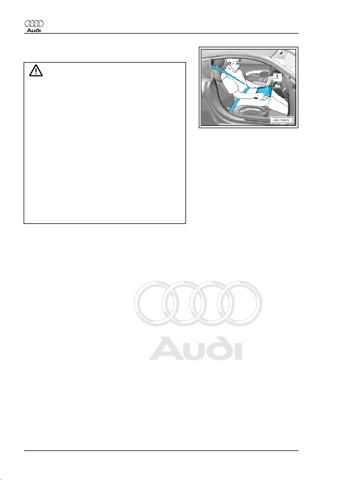
WARNING
Accidents can be caused if the driver is distracted by test
equipment while road-testing, or if test equipment is not prop‐
erly secured.
Injuries can also be caused if the passenger's airbag is trig‐
gered in a collision.
• The use of test equipment while driving causes distraction.
• There is an increased risk of injury if test equipment is not
secured.
TT Coupé:
Test equipment must always be secured on the rear seat with
a strap and operated from the rear seat by a second person.
TT Roadster:
♦ Move the passenger's seat back as far as it will go.
♦ Use only vehicle diagnosis and service information sys‐
tem -VAS 5052- or diagnosis system -VAS 5053- .
♦ The test equipment -1- must rest flat on the passenger's
thighs (as shown in illustration) and must be operated by
the passenger.
1.2 Rules for cleanliness when working on fuel supply system and injection system
Even small amounts of dirt can cause malfunctions. For this rea‐
son, please observe the following rules when working on the fuel
supply system and injection system:
♦ Carefully clean connection points and the surrounding area
with engine cleaner or brake cleaner and dry thoroughly before
opening.
♦ Seal off open lines and connections with clean plugs or sealing
caps immediately.
♦ Place parts that have been removed on a clean surface and
cover them over. Use only lint-free cloths.
♦ Carefully cover or seal open components if repairs cannot be
carried out immediately.
♦ Only install clean components; replacement parts should only
be unpacked immediately prior to installation. Do not use parts
that have been previously unpacked and stored away loose
(e.g. in toolboxes, etc.).
♦ When the system is open: Do not work with compressed air.
Do not move the vehicle unless absolutely necessary.
♦ Protect unplugged electrical connectors against dirt and mois‐
ture and make sure connections are dry when attaching.
2 Rep. Gr.24 - Mixture preparation - injection
Page 7
Protected by copyright. Copying for private or commercial purposes, in part or in whole, is not
permitted unless authorised by AUDI AG. AUDI AG does not guarantee or accept any liability
with respect to the correctness of information in this document. Copyright by AUDI AG.
Audi TT 2007 ➤
Injection and ignition system (6-cyl. 3.2 ltr. 4-valve injection engine) - Edition 07.2007
2 Injection system
2.1 Test data
Engine data 3.2 ltr. / 4V / 184 kW engine
Idling speed
600 ... 700 rpm
Cannot be adjusted; regulated by idling speed stabili‐
sation
Maximum rpm governed by
approx. 6,500 rpm
deactivation of fuel injectors
Fuel pressure at idling speed approx. 4.0 bar
Residual pressure after 10 minutes at least 3.0 bar
Injectors Spray pattern Two-hole nozzle / same for all injectors
Injection quantity
128 … 140 ml
(30 sec.)
1)
•
Current values ⇒ Data sheets for exhaust emission test.
1)
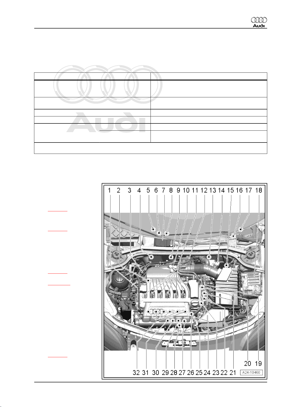
2.2 Overview of fitting locations
1 - 3-pin connector
❑ For knock sensor 1 -
G61-
❑ Fitting location
⇒ page 9
2 - Knock sensor 1 -G61-
❑ Fitting location
⇒ page 9
3 - Activated charcoal filter sol‐
enoid valve 1 -N80-
4 - Lambda probe before cata‐
lytic converter -G39- with
Lambda probe heater -Z19-
❑ Fitting location
⇒ page 7
❑ Removing and installing
⇒ page 32
5 - Electrical connectors
❑ For Lambda probe after
catalytic converter G130- with Lambda
probe 1 heater after cat‐
alytic converter -Z29-
❑ For Lambda probe 2 af‐
ter catalytic converter G131- with Lambda
probe 2 heater after cat‐
alytic converter -Z30-
❑ Fitting location
⇒ page 7
6 - Lambda probe after catalyt‐
ic converter -G130- with Lamb‐
da probe 1 heater after catalyt‐
2. Injection system 3
Page 8
Protected by copyright. Copying for private or commercial purposes, in part or in whole, is not
permitted unless authorised by AUDI AG. AUDI AG does not guarantee or accept any liability
with respect to the correctness of information in this document. Copyright by AUDI AG.
Audi TT 2007 ➤
Injection and ignition system (6-cyl. 3.2 ltr. 4-valve injection engine) - Edition 07.2007
ic converter -Z29-
❑ Fitting location ⇒ page 7
❑ Removing and installing ⇒ page 33
7 - Engine control unit -J623-
❑ Removing and installing ⇒ page 35
8 - Lambda probe 2 after catalytic converter -G131- with Lambda probe 2 heater after catalytic converter -Z30-
❑ Fitting location ⇒ page 7
❑ Removing and installing ⇒ page 33
9 - Lambda probe 2 before catalytic converter -G108- with Lambda probe 2 heater -Z28-
❑ Fitting location ⇒ page 7
❑ Removing and installing ⇒ page 32
10 - Heating element for crankcase breather -N79-
11 - Ignition coils with output stages
❑ Cylinder 1 ignition coil 1 with output stage -N70❑ Cylinder 2 ignition coil 2 with output stage -N127❑ Cylinder 3 ignition coil 3 with output stage -N291❑ Cylinder 4 ignition coil 4 with output stage -N292❑ Cylinder 5 ignition coil 5 with output stage -N323❑ Cylinder 6 ignition coil 6 with output stage -N324❑ Removing and installing ⇒ page 43
12 - Throttle valve module -J338-
❑ Including throttle valve drive for electric throttle -G186- , throttle valve drive angle sender 1 for electric
throttle -G187- and throttle valve drive angle sender 2 for electric throttle -G188-
13 - Electrical connectors
❑ For Lambda probe, before catalytic converter -G39- with Lambda probe heater -Z19❑ For Lambda probe 2, before catalytic converter -G108- with Lambda probe 2 heater -Z28❑ Fitting location ⇒ page 6
14 - Air mass meter -G70-
❑ Removing and installing ⇒ page 14
15 - Clutch position sender -G476-
❑ For vehicles with manual gearbox
❑ Fitting location ⇒ page 6 .
16 - Accelerator position sender -G79- and accelerator position sender 2 -G185-
Fitting location ⇒ page 6
17 - Instrument cluster
❑ With exhaust emissions warning lamp -K83-
18 - Electronics box in engine compartment
❑ With fuel pump relay -J17❑ With Motronic current supply relay -J271❑ With secondary air pump relay -J299❑ Fitting locations ⇒ page 8
19 - Sender 1 for secondary air pressure -G609-
❑ Only for engine code CBRA
❑ Fitting location ⇒ page 10
20 - Hall sender 2 -G163-
❑ Fitting location ⇒ page 9
4 Rep. Gr.24 - Mixture preparation - injection
Page 9
Protected by copyright. Copying for private or commercial purposes, in part or in whole, is not
permitted unless authorised by AUDI AG. AUDI AG does not guarantee or accept any liability
with respect to the correctness of information in this document. Copyright by AUDI AG.
Injection and ignition system (6-cyl. 3.2 ltr. 4-valve injection engine) - Edition 07.2007
21 - Exhaust camshaft control valve 1 -N318-
❑ Brown connector
❑ Fitting location ⇒ page 9
22 - Inlet camshaft control valve 1 -N205-
❑ Black connector
❑ Fitting location ⇒ page 9
23 - Hall sender -G40-
❑ Fitting location ⇒ page 9
24 - Coolant temperature sender -G62-
❑ Fitting location ⇒ page 8
25 - Vacuum unit for intake manifold flaps
❑ Checking ⇒ page 20
❑ Removing and installing ⇒ page 22
26 - Engine speed sender -G28-
❑ Fitting location ⇒ page 8
27 - Variable intake manifold change-over valve -N156-
❑ Fitting location ⇒ page 8
28 - Secondary air pump motor -V101-
❑ Removing and installing ⇒ Rep. Gr. 26
29 - Checking secondary air inlet valve -N112- and secondary air inlet valve 2 -N320-
❑ Only for engine code CBRA
❑ Fitting location ⇒ page 9
30 - Knock sensor 2 -G66-
❑ Fitting location ⇒ page 9
31 - 3-pin connector
❑ For engine speed sender -G28❑ Fitting location ⇒ page 8
32 - Injectors
❑ Cylinder 1 injector for cylinder 1 -N30❑ Cylinder 2 injector for cylinder 2 -N31❑ Cylinder 3 injector for cylinder 3 -N32❑ Cylinder 4 injector for cylinder 4 -N33❑ Cylinder 5 injector for cylinder 5 -N83❑ Cylinder 6 injector for cylinder 6 -N84❑ Checking injection quantity and spray pattern; checking for leaks ⇒ page 29
❑ Removing and installing ⇒ page 27
Audi TT 2007 ➤
2. Injection system 5
Page 10
Protected by copyright. Copying for private or commercial purposes, in part or in whole, is not
permitted unless authorised by AUDI AG. AUDI AG does not guarantee or accept any liability
with respect to the correctness of information in this document. Copyright by AUDI AG.
Audi TT 2007 ➤
Injection and ignition system (6-cyl. 3.2 ltr. 4-valve injection engine) - Edition 07.2007
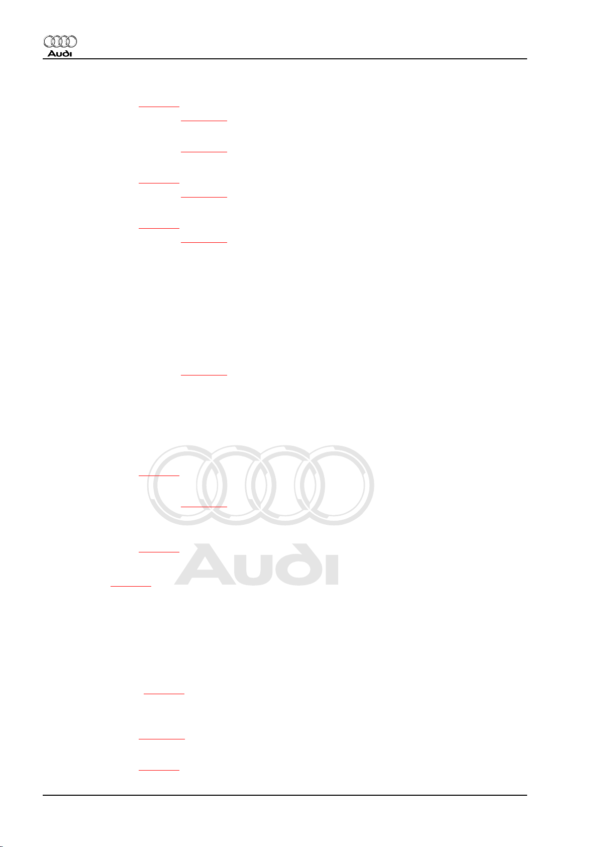
Fitting location of accelerator position sender -G79- with acceler‐
ator position sender 2 -G185-
♦ To unplug the electrical connector -2- press the release tab
and pull off the cable guide -1-.
♦ Removing and installing ⇒ Rep. Gr. 20
Note
Diagram shows set-up on left-hand drive vehicles.
Fitting location of clutch position sender -G476-
♦ On clutch master cylinder-arrow-.
♦ Removing and installing ⇒ Rep. Gr. 30
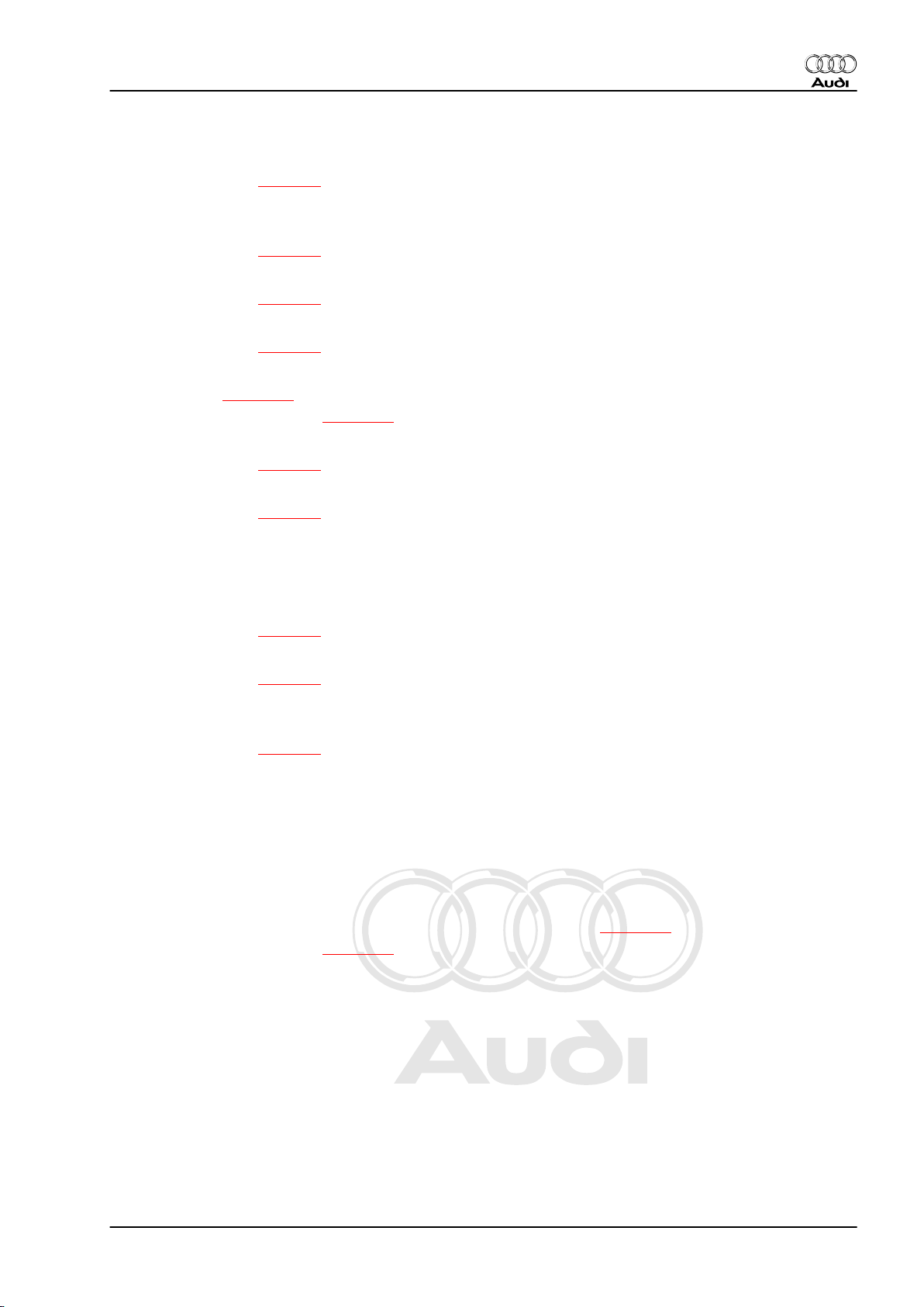
Fitting location of connectors for Lambda probes before catalytic
converter
1 - Lambda probe 2 before catalytic converter -G108- with
Lambda probe 2 heater -Z28-
2 - Lambda probe before catalytic converter -G39- with Lamb‐
da probe heater -Z19-
Note
Disregard -item 3-.
6 Rep. Gr.24 - Mixture preparation - injection
Page 11
Protected by copyright. Copying for private or commercial purposes, in part or in whole, is not
permitted unless authorised by AUDI AG. AUDI AG does not guarantee or accept any liability
with respect to the correctness of information in this document. Copyright by AUDI AG.
Injection and ignition system (6-cyl. 3.2 ltr. 4-valve injection engine) - Edition 07.2007
Fitting location and tightening torque of Lambda probes before
catalytic converter
♦ In front exhaust pipe
1 - Lambda probe 2 before catalytic converter -G108- with
Lambda probe 2 heater -Z28-
2 - Lambda probe before catalytic converter -G39- with Lamb‐
da probe heater -Z19-
– Tighten Lambda probes to 55 Nm.
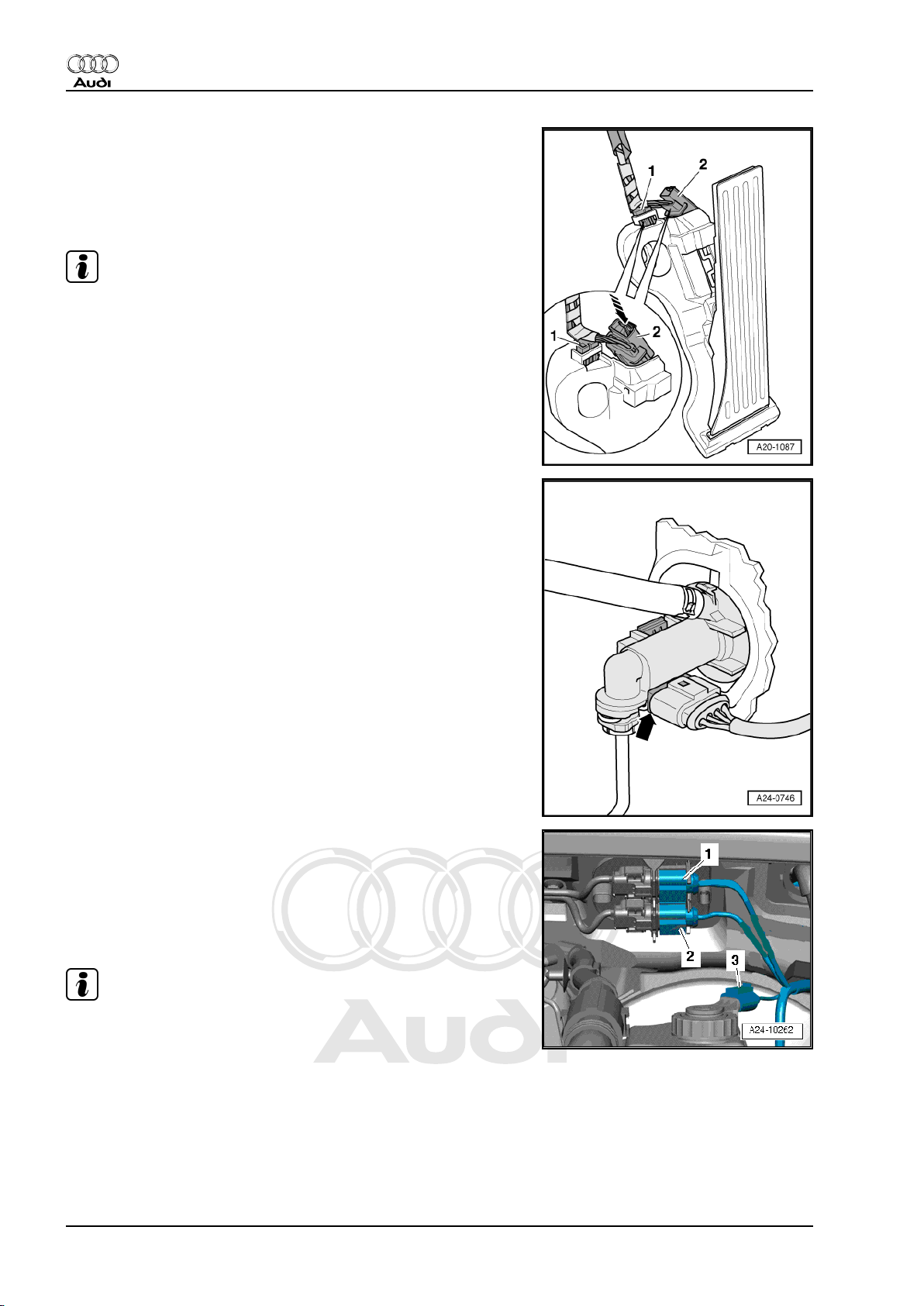
Fitting location of connectors for Lambda probes after catalytic
converter
♦ On underside of vehicle (right-side)
– Remove nuts -1- and -2- on retainer for electrical connectors.
Note
Audi TT 2007 ➤
Disregard -item 3-.
– Detach cover.
1 - Lambda probe after catalytic converter -G130- with Lambda
probe 1 heater after catalytic converter -Z29-
2 - Lambda probe 2 after catalytic converter -G131- with Lamb‐
da probe 2 heater after catalytic converter -Z30-
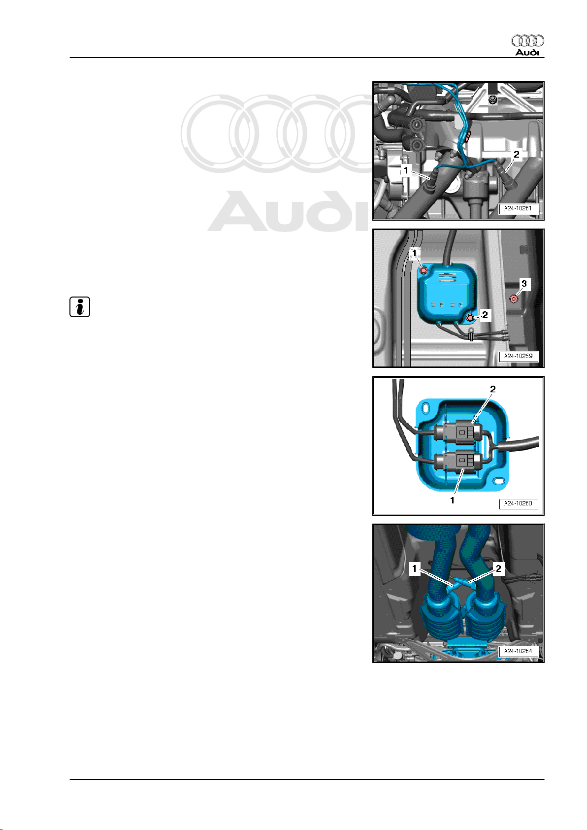
Fitting location and tightening torque of Lambda probes after cat‐
alytic converter
♦ In catalytic converters.
1 - Lambda probe 2 after catalytic converter -G131- with Lamb‐
da probe 2 heater after catalytic converter -Z30-
2 - Lambda probe after catalytic converter -G130- with Lambda
probe 1 heater after catalytic converter -Z29-
– Tighten Lambda probes to 55 Nm.
2. Injection system 7
Page 12
Protected by copyright. Copying for private or commercial purposes, in part or in whole, is not
permitted unless authorised by AUDI AG. AUDI AG does not guarantee or accept any liability
with respect to the correctness of information in this document. Copyright by AUDI AG.
Audi TT 2007 ➤
Injection and ignition system (6-cyl. 3.2 ltr. 4-valve injection engine) - Edition 07.2007
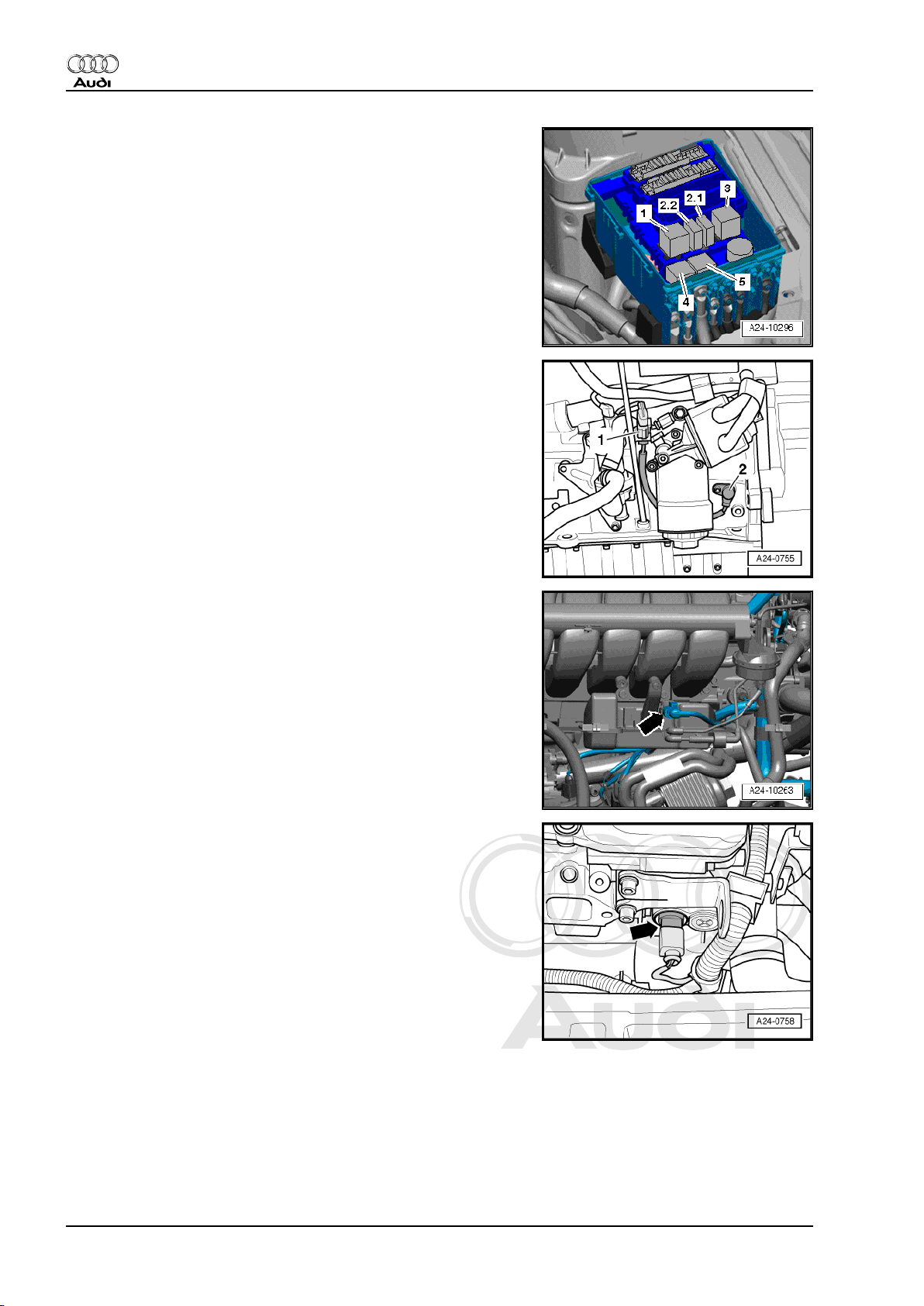
Fitting locations in electronics box in engine compartment
2.1 - Electric fuel pump 2 relay -J49-
2.2 - Continued coolant circulation relay -J151-
3 - Secondary air pump relay -J299-
4 - Motronic current supply relay -J271-
5 - Fuel pump relay -J17-
Fitting location: engine speed sender -G28- with 3-pin connector
♦ At front of engine.
1 - 3-pin connector
2 - Engine speed sender -G28-
Fitting location of intake manifold change-over valve -N156-
♦ On vacuum reservoir (at front of engine) -arrow-.
Fitting location of coolant temperature sender -G62-
♦ At front left of cylinder head -arrow-.
♦ Removing and installing ⇒ Rep. Gr. 19
8 Rep. Gr.24 - Mixture preparation - injection
Page 13
Protected by copyright. Copying for private or commercial purposes, in part or in whole, is not
permitted unless authorised by AUDI AG. AUDI AG does not guarantee or accept any liability
with respect to the correctness of information in this document. Copyright by AUDI AG.
Injection and ignition system (6-cyl. 3.2 ltr. 4-valve injection engine) - Edition 07.2007
Fitting location of knock sensor 1 -G61-
♦ At rear right on cylinder block.
1 - Knock sensor 1 -G61-
2 - 3-pin connector
Fitting location of knock sensor 2 -G66-
♦ At front of cylinder block -arrow-.
Audi TT 2007 ➤
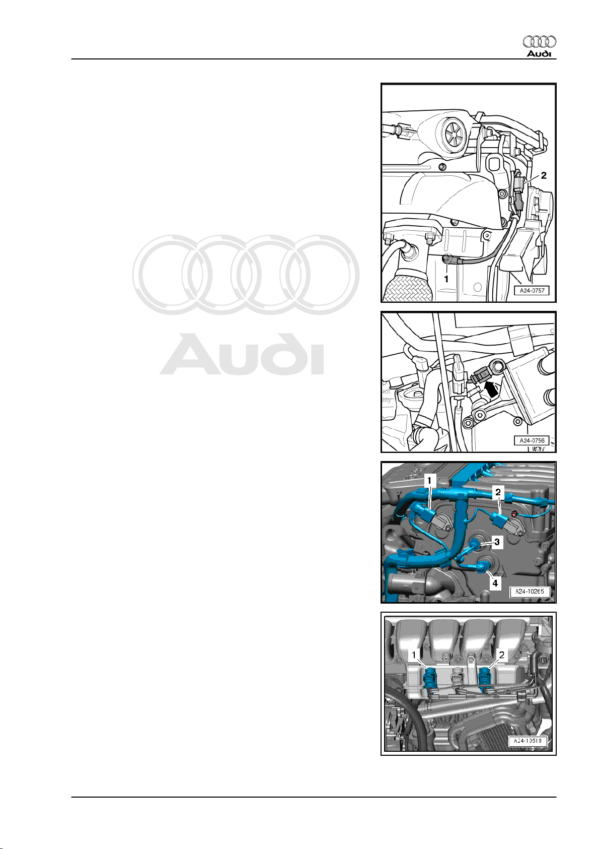
Fitting location of Hall sender and camshaft control valves
♦ On left side of cylinder head.
1 - Hall sender -G40-
2 - Hall sender 2 -G163-
3 - Inlet camshaft control valve 1 -N205-
4 - Exhaust camshaft control valve 1 -N318-
Fitting location of secondary air inlet valves (engine code CBRA)
♦ At vacuum reservoir (at front of engine)
1 - Secondary air inlet valve -N112-
2 - Secondary air inlet valve 2 -N320-
♦ Removing and installing ⇒ Rep. Gr. 26
2. Injection system 9
Page 14
Protected by copyright. Copying for private or commercial purposes, in part or in whole, is not
permitted unless authorised by AUDI AG. AUDI AG does not guarantee or accept any liability
with respect to the correctness of information in this document. Copyright by AUDI AG.
Audi TT 2007 ➤
Injection and ignition system (6-cyl. 3.2 ltr. 4-valve injection engine) - Edition 07.2007
Fitting location of sender 1 for secondary air pressure -G609(engine code CBRA)
♦ Near throttle valve module -J338-
1 - Sender 1 for secondary air pressure -G609-
♦ Removing and installing ⇒ Rep. Gr. 26
Note
Disregard -arrows-.
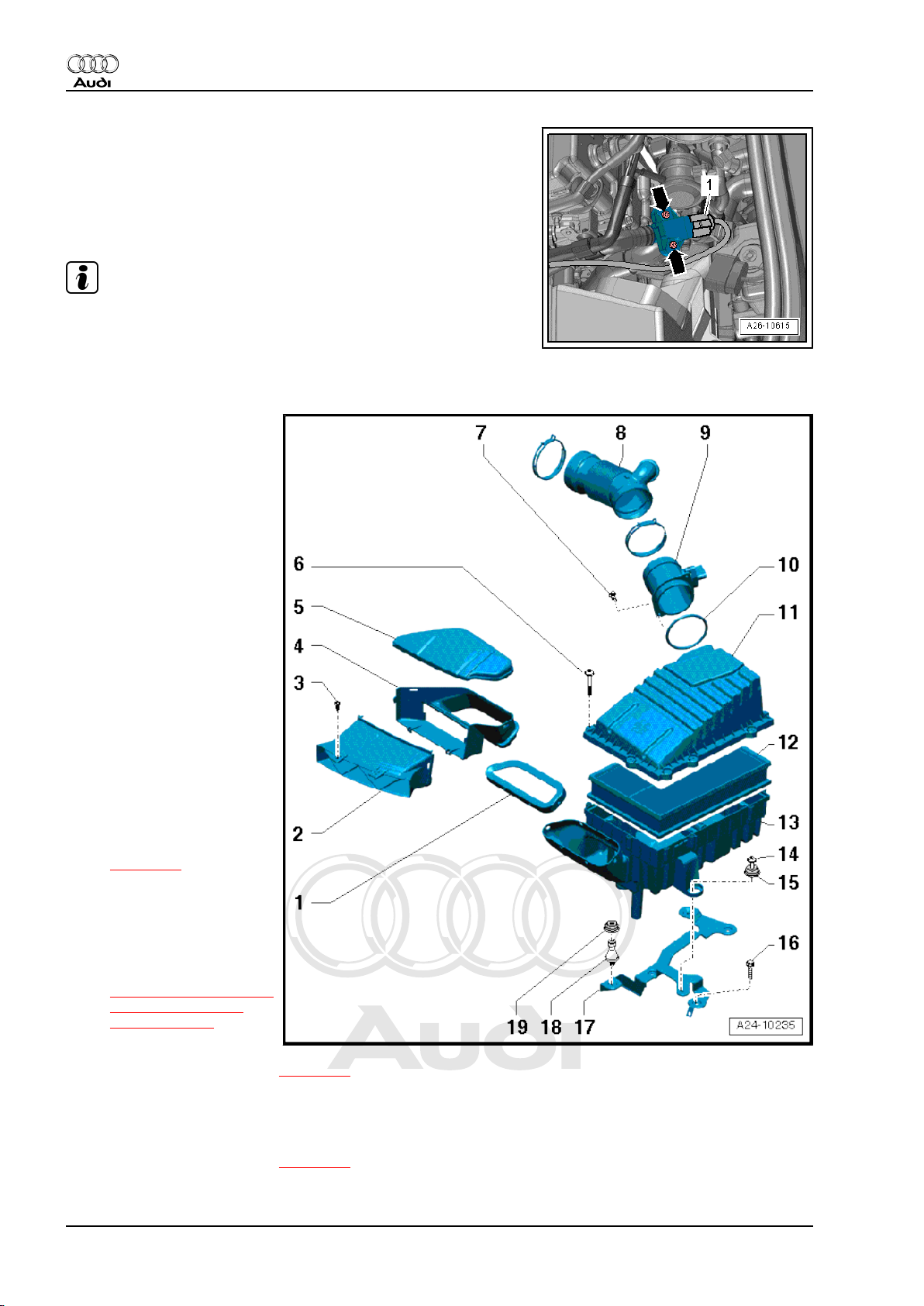
2.3 Air cleaner - exploded view
1 - Gasket
❑ Clipped into air cleaner
housing (bottom sec‐
tion)
2 - Front air duct
❑ Clean out dirt, leaves
and salt deposits
3 - Bolt
❑ 2 Nm
4 - Lower part of air duct
❑ Clean out dirt, leaves
and salt deposits
5 - Air duct cover
6 - Bolt
❑ 5 Nm
7 - Bolt
❑ 3 Nm
8 - Air hose
9 - Air mass meter -G70-
❑ Removing and installing
⇒ page 14
10 - Seal
❑ Renew if damaged
11 - Air cleaner housing (top
section)
❑ Removing and installing
⇒ “2.4 Removing and in‐
stalling air filter ele‐
ment”, page 12
12 - Air filter element
❑ Removing and installing ⇒ page 12
❑ Always use genuine part for air filter element
❑ Observe change intervals ⇒ Maintenance ; Booklet 810
13 - Air cleaner housing (bottom section)
❑ Removing and installing ⇒ page 13
❑ Clean out dirt, leaves and salt deposits
10 Rep. Gr.24 - Mixture preparation - injection
Page 15

Protected by copyright. Copying for private or commercial purposes, in part or in whole, is not
permitted unless authorised by AUDI AG. AUDI AG does not guarantee or accept any liability
with respect to the correctness of information in this document. Copyright by AUDI AG.
Injection and ignition system (6-cyl. 3.2 ltr. 4-valve injection engine) - Edition 07.2007
14 - Bolt
❑ 10 Nm
15 - Rubber grommet
❑ Captive
16 - Bolt
❑ 10 Nm
17 - Bracket for air cleaner housing
18 - Retaining peg
❑ 10 Nm
19 - Rubber grommet
Audi TT 2007 ➤
2. Injection system 11
Page 16

Protected by copyright. Copying for private or commercial purposes, in part or in whole, is not
permitted unless authorised by AUDI AG. AUDI AG does not guarantee or accept any liability
with respect to the correctness of information in this document. Copyright by AUDI AG.
Audi TT 2007 ➤
Injection and ignition system (6-cyl. 3.2 ltr. 4-valve injection engine) - Edition 07.2007
2.4 Removing and installing air filter ele‐
ment
Removing
– Detach resonance pipe -2- from air intake hose.
– Disconnect air intake hose -1- from throttle valve module -
J338- .
– Detach electrical connector -3- for air mass meter -G70- .
– Detach air cleaner housing (top section) -arrow- and take out
air filter element.
Installing
• Tightening torque ⇒ page 10 .
Installation is carried out in the reverse order; note the following:
To ensure the proper function of the air mass meter it is important
to observe the following notes and instructions.
Note
♦
If the air filter element is very dirty or wet, dirt or water could
reach the air mass meter and affect the air mass value. This
would lead to loss of power, since a smaller injection quantity
is calculated.
♦
Always use genuine part for air filter element.
♦
The air cleaner housing MUST be clean.
♦
Secure all hose connections with the correct type of hose clips
(same as original equipment) ⇒ Electronic parts catalogue .
♦
To prevent malfunctions, cover all critical parts of the engine
air intake tract (air mass meter, intake pipes, etc.) with a clean
cloth when blowing out the air cleaner housing with com‐
pressed air.
♦
Please observe requirements for disposal.
– Blow out water drain (small hole in bottom section of air clean‐
er housing) with compressed air.
– Clean salt residue, dirt and leaves out of air cleaner housing
(top and bottom sections); use a vacuum cleaner if necessary.
– Check for salt residue, dirt and leaves in air mass meter and
air intake hose (engine intake side).
– Check for dirt and leaves in air duct going from lock carrier to
air cleaner housing.
– When installing the air filter element, check that it is properly
centred in the retainer in the air cleaner housing (bottom sec‐
tion).
– Fit the top section of the air cleaner housing carefully on the
bottom section, without using force. Make sure the top section
of the air cleaner housing is fitted straight on the air filter ele‐
ment (note position of sealing lip on air filter element).
– Ensure secure fit of intake hose at air mass meter.
12 Rep. Gr.24 - Mixture preparation - injection
Page 17

Protected by copyright. Copying for private or commercial purposes, in part or in whole, is not
permitted unless authorised by AUDI AG. AUDI AG does not guarantee or accept any liability
with respect to the correctness of information in this document. Copyright by AUDI AG.
Injection and ignition system (6-cyl. 3.2 ltr. 4-valve injection engine) - Edition 07.2007
2.5 Removing and installing air cleaner housing
Removing
– Remove air filter element ⇒ page 12 .
– Unscrew bolts -arrows- and remove air duct.
– Unscrew air cleaner housing (lower section) -arrows-.
Installing
• Tightening torques ⇒ page 10 .
Installation is carried out in the reverse order; note the following.
Audi TT 2007 ➤
Note
♦
The air cleaner housing MUST be clean.
♦
Secure all hose connections with the correct type of hose clips
(same as original equipment) ⇒ Electronic parts catalogue .
♦
To prevent malfunctions, cover all critical parts of the engine
air intake tract (air mass meter, intake pipes, etc.) with a clean
cloth when blowing out the air cleaner housing with com‐
pressed air.
– Blow out water drain (small hole in bottom section of air clean‐
er housing) with compressed air.
– Clean salt residue, dirt and leaves out of air cleaner housing
(top and bottom sections); use a vacuum cleaner if necessary.
– Check for salt residue, dirt and leaves in air mass meter and
air intake hose (engine intake side).
– Check for dirt and leaves in air duct going from lock carrier to
air cleaner housing.
– Fit the top section of the air cleaner housing carefully on the
bottom section, without using force. Make sure the top section
of the air cleaner housing is fitted straight on the air filter ele‐
ment (note position of sealing lip on air filter element).
2. Injection system 13
Page 18

Protected by copyright. Copying for private or commercial purposes, in part or in whole, is not
permitted unless authorised by AUDI AG. AUDI AG does not guarantee or accept any liability
with respect to the correctness of information in this document. Copyright by AUDI AG.
Audi TT 2007 ➤
Injection and ignition system (6-cyl. 3.2 ltr. 4-valve injection engine) - Edition 07.2007
2.6 Removing and installing air mass meter
-G70-
Removing
– Detach electrical connector -1- for air mass meter -G70- .
– Detach air intake hose -arrows-.
– Remove bolts -arrows-.
– Then carefully pull air mass meter -G70- out of guide on air
cleaner housing (top section).
Installing
• Tightening torque ⇒ page 10 .
Installation is carried out in the reverse order; note the following.
To ensure the proper function of the air mass meter it is important
to observe the following notes and instructions.
Note
♦
Renew O-ring.
♦
If the air filter element is very dirty or wet, dirt or water could
reach the air mass meter and affect the air mass value. This
would lead to loss of power, since a smaller injection quantity
is calculated.
♦
Always use genuine part for air filter element.
♦
Use silicone-free lubricant when fitting air intake hose.
♦
Secure all hose connections with the correct type of hose clips
(same as original equipment) ⇒ Electronic parts catalogue .
14 Rep. Gr.24 - Mixture preparation - injection
Page 19

Protected by copyright. Copying for private or commercial purposes, in part or in whole, is not
permitted unless authorised by AUDI AG. AUDI AG does not guarantee or accept any liability
with respect to the correctness of information in this document. Copyright by AUDI AG.
Injection and ignition system (6-cyl. 3.2 ltr. 4-valve injection engine) - Edition 07.2007
2.7 Intake manifold - exploded view
1 - Change-over barrel
2 - Bearing bush
3 - O-ring
❑ Renew
4 - Bolt
5 - Bearing cap
6 - Intake manifold
7 - Bolt
❑ 20 Nm
8 - Bolt
❑ 20 Nm
9 - Seal
10 - Connection for crankcase
breather
❑ With heater element for
crankcase breather N79-
11 - O-ring
12 - Throttle valve module J338-
❑ Removing and installing
⇒ page 19
13 - Bolt
❑ 10 Nm
14 - Bolt
❑ 20 Nm
15 - Heat shield for exhaust
manifold
❑ With support for intake manifold
16 - Gasket
❑ Renew
❑ Insert into intake manifold
17 - Bolt
❑ 13 Nm
18 - Bolt
❑ 10 Nm
19 - Vacuum unit
❑ For intake manifold flaps
❑ Checking ⇒ page 20
❑ Removing and installing ⇒ page 22
20 - Vacuum connection
❑ To intake manifold change-over valve -N156-
21 - O-ring
❑ Renew
Audi TT 2007 ➤
2. Injection system 15
Page 20

Protected by copyright. Copying for private or commercial purposes, in part or in whole, is not
permitted unless authorised by AUDI AG. AUDI AG does not guarantee or accept any liability
with respect to the correctness of information in this document. Copyright by AUDI AG.
Audi TT 2007 ➤
Injection and ignition system (6-cyl. 3.2 ltr. 4-valve injection engine) - Edition 07.2007
22 - Bearing bush
Engine lifting eye to cylinder head: tightening torque
Tighten bolts -arrows- to 20 Nm.
Oil dipstick and vacuum reservoir: tightening torques
Tighten bolts -3- and -4- to 5 Nm.
2.8 Removing and installing intake manifold
Removing
Note
All cable ties which are released or cut open when removing must
be refitted in the same position when installing.
Caution
Observe notes on procedure for disconnecting the battery ⇒
Rep. Gr. 27 .
– Disconnect earth wire at battery with ignition switched off.
– Remove air filter element ⇒ page 12 .
– Remove air cleaner housing ⇒ page 13 .
16 Rep. Gr.24 - Mixture preparation - injection
Page 21

Protected by copyright. Copying for private or commercial purposes, in part or in whole, is not
permitted unless authorised by AUDI AG. AUDI AG does not guarantee or accept any liability
with respect to the correctness of information in this document. Copyright by AUDI AG.
Injection and ignition system (6-cyl. 3.2 ltr. 4-valve injection engine) - Edition 07.2007
– Unplug electrical connectors -1, 2, 3- and move wiring clear.
– Remove crankcase breather hose -4-.
– Remove ignition coils ⇒ page 43 .
– Remove throttle valve module -J338- ⇒ page 19 .
– Disconnect vacuum hoses -1, 3, 4- at rear of intake manifold.
Vehicles with engine code letters CBRA:
– Disconnect vacuum hose -2- leading to fuel system diagnostic
pump -V144- .
All vehicles (continued):
– Unbolt hose bracket from intake manifold -arrows- and move
clear to rear, with hoses attached.
Audi TT 2007 ➤
– Remove rear securing bolts -arrows- for intake manifold.
– Unhook connector -arrow- for engine speed sender -G28-
from bracket on guide tube for oil dipstick.
2. Injection system 17
Page 22

Protected by copyright. Copying for private or commercial purposes, in part or in whole, is not
permitted unless authorised by AUDI AG. AUDI AG does not guarantee or accept any liability
with respect to the correctness of information in this document. Copyright by AUDI AG.
Audi TT 2007 ➤
Injection and ignition system (6-cyl. 3.2 ltr. 4-valve injection engine) - Edition 07.2007
– Pull out oil dipstick.
– Remove bolt -3-, pull out guide tube for oil dipstick -2- and
move clear to one side.
– Unscrew bolt -4- and detach vacuum reservoir -1- from intake
manifold.
– Move vacuum reservoir to side (hoses remain attached).
– Release relay lever -arrow- and detach.
– Remove bolts -1- and -2-.
– Detach vacuum unit for intake manifold change-over and
move to side with vacuum hose -3- connected.
– Unscrew bolts -arrows- and remove engine lifting eye (left-
side).
– Unscrew bolts -arrows- at front of intake manifold.
18 Rep. Gr.24 - Mixture preparation - injection
Page 23

Protected by copyright. Copying for private or commercial purposes, in part or in whole, is not
permitted unless authorised by AUDI AG. AUDI AG does not guarantee or accept any liability
with respect to the correctness of information in this document. Copyright by AUDI AG.
Injection and ignition system (6-cyl. 3.2 ltr. 4-valve injection engine) - Edition 07.2007
– To avoid damaging the surface of the intake manifold, place a
clean cloth -1- over the lock carrier.
– Swing the intake manifold forwards -arrow A- and take it out
to the left -arrow B-.
Note
Cover or plug the intake ports in the cylinder head with a clean
cloth or foam plastic to prevent small items from dropping in.
Installing
• Tightening torques ⇒ page 15 .
Installation is carried out in the reverse order; note the following:
Note
Renew seals and gaskets.
– Install ignition coils ⇒ page 43 .
– Install throttle valve module -J338- ⇒ page 19 .
– Install air cleaner housing ⇒ page 13 .
– Install air filter element ⇒ page 12 .
– Connect earth strap to battery ⇒ Rep. Gr. 27 .
Audi TT 2007 ➤
2.9 Removing and installing throttle valve module -J338-
Removing
– Detach air intake hose -arrows-.
Note
Disregard -item 1-.
– Unplug electrical connector -3-.
– Remove crankcase breather hose -1-.
– Move Lambda probe wiring at throttle valve module -J338-
clear
Note
Disregard -item 2-.
2. Injection system 19
Page 24

Protected by copyright. Copying for private or commercial purposes, in part or in whole, is not
permitted unless authorised by AUDI AG. AUDI AG does not guarantee or accept any liability
with respect to the correctness of information in this document. Copyright by AUDI AG.
Audi TT 2007 ➤
Injection and ignition system (6-cyl. 3.2 ltr. 4-valve injection engine) - Edition 07.2007
– Remove bolts -arrows-.
– Detach throttle valve module -J338- from intake manifold.
Installing
• Tightening torque ⇒ page 15 .
Install in reverse order.
2.10 Checking vacuum unit for intake mani‐
fold flaps
Only perform this test if there is a loss of engine torque, poor flex‐
ibility or lack of pulling power.
Special tools and workshop equipment required
♦ Hand-operated vacuum pump -VAS 6213-
Procedure
– Start engine.
– Abruptly floor accelerator pedal and observe linkage at vac‐
uum unit.
• The linkage should move -arrow-.
Proceed as follows if the linkage on the vacuum unit does not
move:
♦ Check vacuum system for leaks.
♦ Check that linkage of change-over mechanism moves freely.
♦ Check proper connection of vacuum lines.
♦ Check vacuum hoses.
20 Rep. Gr.24 - Mixture preparation - injection
Page 25

Protected by copyright. Copying for private or commercial purposes, in part or in whole, is not
permitted unless authorised by AUDI AG. AUDI AG does not guarantee or accept any liability
with respect to the correctness of information in this document. Copyright by AUDI AG.
Injection and ignition system (6-cyl. 3.2 ltr. 4-valve injection engine) - Edition 07.2007
If no fault is found:
– Remove air cleaner housing ⇒ page 13 .
– Detach vacuum hose -3- from vacuum unit.
Note
Disregard items marked -1-, -2- and -arrows-.
– Connect hand-operated vacuum pump -VAS 6213- to vacuum
unit as shown in illustration.
Audi TT 2007 ➤
– Use hand-operated vacuum pump to generate vacuum.
– At the same time observe linkage at vacuum unit:
• The linkage should move -arrow-.
– Vent vacuum hand pump.
• The linkage should return to its original position.
Note
Observe the movement of the linkage over the complete range of
travel. It should move steadily and smoothly.
If the linkage on the vacuum unit does not move, or only moves
jerkily:
– Renew vacuum unit ⇒ page 22 .
2. Injection system 21
Page 26

Protected by copyright. Copying for private or commercial purposes, in part or in whole, is not
permitted unless authorised by AUDI AG. AUDI AG does not guarantee or accept any liability
with respect to the correctness of information in this document. Copyright by AUDI AG.
Audi TT 2007 ➤
Injection and ignition system (6-cyl. 3.2 ltr. 4-valve injection engine) - Edition 07.2007
2.11 Removing and installing vacuum unit for intake manifold flaps
Removing
– Release relay lever -arrow- and detach.
– Remove bolts -1- and -2-.
– Pull vacuum unit off intake manifold.
– Detach vacuum hose -3- from vacuum unit.
Installing
• Tightening torque ⇒ page 15 .
Installation is carried out in the reverse order; note the following:
Note
Renew O-ring.
2.12 Checking fuel pressure regulator and re‐
sidual pressure
Note
The fuel pressure regulator is integrated in the fuel filter and can‐
not be renewed on its own.
Special tools and workshop equipment required
♦ Hose clamps for hoses up to 25 mm -3094-
♦ K-Jetronic tester -V.A.G 1318- with adapters -V.A.G 1318/11- ,
-V.A.G 1318/17- and -V.A.G 1318/23-
22 Rep. Gr.24 - Mixture preparation - injection
Page 27

Protected by copyright. Copying for private or commercial purposes, in part or in whole, is not
permitted unless authorised by AUDI AG. AUDI AG does not guarantee or accept any liability
with respect to the correctness of information in this document. Copyright by AUDI AG.
Injection and ignition system (6-cyl. 3.2 ltr. 4-valve injection engine) - Edition 07.2007
Procedure
• Fuel pump relay OK.
• Fuel pump OK; checking ⇒ Rep. Gr. 20 .
• Fuel filter OK
• Battery voltage at least 12.5 V.
Measuring fuel pressure:
– Press the two clips in direction of the -arrows- and remove
cover from electronics box in engine compartment.
– Disconnect electric fuel pump 2 relay -J49- -item 2.1-.
Audi TT 2007 ➤
Note
Disconnecting the electric fuel pump 2 relay -J49- will prevent the
fuel pump from being activated when the driver's door is opened.
WARNING
The fuel system is pressurised. Before opening the system
place a clean cloth around the connection. Then release pres‐
sure by carefully loosening the connection.
– Disconnect fuel supply pipe -arrow- by pulling release ring.
– Disconnect fuel supply pipe -arrow- at fuel rail.
2. Injection system 23
Page 28

Protected by copyright. Copying for private or commercial purposes, in part or in whole, is not
permitted unless authorised by AUDI AG. AUDI AG does not guarantee or accept any liability
with respect to the correctness of information in this document. Copyright by AUDI AG.
Audi TT 2007 ➤
Injection and ignition system (6-cyl. 3.2 ltr. 4-valve injection engine) - Edition 07.2007
– Connect the K-Jetronic tester -V.A.G 1318- with adapters -
V.A.G 1318/11- , -V.A.G 1318/17- and -V.A.G 1318/23- .
– Connect pressure tester to fuel supply hose.
– Connect a fuel-resistant auxiliary hose between fuel rail and
tester.
Note
Use hose clips -arrows- to secure the auxiliary hose.
– Open cut-off valve on pressure tester.
• Lever points in direction of flow.
– Start the engine and run at idling speed.
– Measure the fuel pressure.
• Specification: approx. 4.0 bar
– Switch off ignition.
If specification is not obtained:
– Check fuel pump delivery rate ⇒ Rep. Gr. 20 .
Checking leakage and residual pressure:
– Check leak-tightness and residual pressure by watching the
drop in pressure on the pressure gauge.
• After 10 minutes pressure should still be at least 3.0 bar.
If the residual pressure drops below 3.0 bar:
– Start the engine and run at idling speed.
– Allow pressure to build up, then switch off ignition. At the same
time close cut-off valve of K-Jetronic tester -V.A.G 1318- .
• Lever is at right angle to direction of flow -arrow-.
– Observe pressure drop on pressure gauge.
If the pressure drops again:
– Check pipe connections, injectors and O-rings on fuel rail for
leaks.
– Check pressure gauge for leaks.
If the pressure now does not drop:
– Open cut-off valve on pressure gauge (lever points in direction
of flow).
– Remove rear seat bench ⇒ Rep. Gr. 72 .
24 Rep. Gr.24 - Mixture preparation - injection
Page 29

Protected by copyright. Copying for private or commercial purposes, in part or in whole, is not
permitted unless authorised by AUDI AG. AUDI AG does not guarantee or accept any liability
with respect to the correctness of information in this document. Copyright by AUDI AG.
Injection and ignition system (6-cyl. 3.2 ltr. 4-valve injection engine) - Edition 07.2007
– Unclip the retaining tabs -arrows- for the flange cover (right-
side).
– Disconnect fuel return pipe -arrow- by pressing release tab.
Audi TT 2007 ➤
2. Injection system 25
Page 30

Protected by copyright. Copying for private or commercial purposes, in part or in whole, is not
permitted unless authorised by AUDI AG. AUDI AG does not guarantee or accept any liability
with respect to the correctness of information in this document. Copyright by AUDI AG.
Audi TT 2007 ➤
Injection and ignition system (6-cyl. 3.2 ltr. 4-valve injection engine) - Edition 07.2007
– Connect adapter hose -1318/17-1- to fuel return pipe.
– Clamp off adapter hose using hose clamp -3094- .
Note
Do not attach hose clamp -3094- directly to fuel pipe - Danger of
damage.
– Cover the return pipe connection with a cloth.
– Start the engine and briefly run at idling speed.
– Allow pressure to build up, then switch off ignition.
– Observe pressure drop on pressure gauge.
If pressure does not drop, non-return valve of fuel pump is de‐
fective.
– Renew fuel pump ⇒ Rep. Gr. 20 .
If the pressure drops again:
– Renew fuel filter with integral fuel pressure regulator ⇒ Rep.
Gr. 20 .
Note
Before removing the pressure tester, release the fuel pressure by
opening the cut-off valve. Hold a container under the connection.
– Installation is carried out in the reverse order; note the follow‐
ing:
Note
Secure all hose connections with the correct type of hose clips
(same as original equipment) ⇒ Electronic parts catalogue .
– Fit electric fuel pump 2 relay -J49- -item 2.1- back into relay
and fuse holder.
– Install rear seat bench ⇒ Rep. Gr. 72 .
26 Rep. Gr.24 - Mixture preparation - injection
Page 31

Protected by copyright. Copying for private or commercial purposes, in part or in whole, is not
permitted unless authorised by AUDI AG. AUDI AG does not guarantee or accept any liability
with respect to the correctness of information in this document. Copyright by AUDI AG.
Injection and ignition system (6-cyl. 3.2 ltr. 4-valve injection engine) - Edition 07.2007
2.13 Fuel rail with injectors - exploded view
1 - Fuel rail
2 - Fuel hose
WARNING
Unplug electric fuel
pump 2 relay -J49- be‐
fore detaching fuel hose
⇒ page 28 .
3 - Bolt
❑ 10 Nm
4 - O-ring
❑ Removing and installing
⇒ page 27
❑ Renew
❑ Lubricate lightly with
clean engine oil
5 - Retaining clip
❑ After installing injector,
make sure the retaining
clip is seated correctly.
6 - Injector
7 - O-ring
❑ Removing and installing
⇒ page 27
❑ Renew
❑ Lubricate lightly with
clean engine oil
Audi TT 2007 ➤
2.14 Removing and installing injectors
Removing
WARNING
The fuel system is pressurised. Wrap a cloth around the con‐
nection before opening the system. Then release pressure by
carefully loosening the connection.
2. Injection system 27
Page 32

Protected by copyright. Copying for private or commercial purposes, in part or in whole, is not
permitted unless authorised by AUDI AG. AUDI AG does not guarantee or accept any liability
with respect to the correctness of information in this document. Copyright by AUDI AG.
Audi TT 2007 ➤
Injection and ignition system (6-cyl. 3.2 ltr. 4-valve injection engine) - Edition 07.2007
– Press the two clips in direction of the -arrows- and remove
cover from electronics box in engine compartment.
– Detach electric fuel pump 2 relay -J49- -item 2.1-.
Note
Disconnecting the electric fuel pump 2 relay -J49- will prevent the
fuel pump from being activated when the driver's door is opened.
– Remove intake manifold ⇒ page 16 .
– Move wiring harness -1- at fuel rail clear.
– Remove bolts -arrows-.
– Detach fuel rail -2- with injectors from cylinder head and lay it
aside with fuel hose connected.
– Pull off retaining clip and detach appropriate injector.
Installing
• Tightening torque ⇒ page 27 .
Installation is carried out in the reverse order; note the following:
• Renew the O-rings at all opened connections. (When renew‐
ing the front O-ring, ensure that the plastic cap is not removed
from the injector head. The O-ring must be pulled off over the
plastic cap).
• Lubricate the O-rings with clean engine oil.
• Make sure injectors are installed in correct position.
• Make sure retaining clips are properly connected.
• Position fuel rail together with injectors (properly secured)
against intake manifold and press into place evenly.
– Install intake manifold ⇒ page 16 .
28 Rep. Gr.24 - Mixture preparation - injection
Page 33

Protected by copyright. Copying for private or commercial purposes, in part or in whole, is not
permitted unless authorised by AUDI AG. AUDI AG does not guarantee or accept any liability
with respect to the correctness of information in this document. Copyright by AUDI AG.
Audi TT 2007 ➤
Injection and ignition system (6-cyl. 3.2 ltr. 4-valve injection engine) - Edition 07.2007
– Fit electric fuel pump 2 relay -J49- -item 2.1- back into relay
and fuse holder.
2.15 Checking injection quantity and spray pattern of injectors; checking for leaks
Special tools and workshop
equipment required
♦ Remote control -V.A.G
1348/3A- for V.A.G 1348
with adapter cable V.A.G 1348/3-2-
♦ Auxiliary measuring set -
V.A.G 1594C-
♦ Adapter cable, 121-pin -
V.A.G 1598/31- (test box)
♦ Injection rate tester -
V.A.G 1602-
Procedure
• Fuel pressure OK; testing ⇒ page 22 .
– Remove intake manifold ⇒ page 16 .
– Remove fuel rail together with injectors ⇒ page 27 . Fuel hose
remains connected.
2. Injection system 29
Page 34

Protected by copyright. Copying for private or commercial purposes, in part or in whole, is not
permitted unless authorised by AUDI AG. AUDI AG does not guarantee or accept any liability
with respect to the correctness of information in this document. Copyright by AUDI AG.
Audi TT 2007 ➤
Injection and ignition system (6-cyl. 3.2 ltr. 4-valve injection engine) - Edition 07.2007
Checking for leaks
– Press the two clips in direction of the -arrows- and remove
cover from electronics box in engine compartment.
– Detach fuse at “position 1” -arrow- from “fuse holder 2” (brown)
-item 2-.
– Connect remote control -V.A.G 1348/3A- for V.A.G 1348 with
adapter cable -V.A.G 1348/3-2- as follows:
♦ To contact for fuse for fuel pump (fuse is detached);
♦ To “+” wire at front of electronics box in engine compartment.
– Connect battery earth cable.
– Press remote control button -V.A.G 1348/3 A- .
• The fuel pump should run.
– Visually check the fuel injectors for leaks.
• When the fuel pump is running, no more than 1 to 2 drops a
minute should escape from any one of the injectors.
If the fuel loss is greater:
– Renew defective fuel injector ⇒ page 27 .
Checking injection quantity
– Unplug electrical connectors for injectors.
– Place one injector in a measuring glass for injection rate tester
-V.A.G 1602- .
30 Rep. Gr.24 - Mixture preparation - injection
Page 35

Protected by copyright. Copying for private or commercial purposes, in part or in whole, is not
permitted unless authorised by AUDI AG. AUDI AG does not guarantee or accept any liability
with respect to the correctness of information in this document. Copyright by AUDI AG.
Injection and ignition system (6-cyl. 3.2 ltr. 4-valve injection engine) - Edition 07.2007
– Using a test lead and crocodile clamp from auxiliary measuring
set -V.A.G 1594C- , connect one contact of injector to earth
“–”.
– Connect second contact of injector to remote control -
V.A.G 1348/3 A- using adapter cable -V.A.G 1348/3-2- .
– Connect crocodile clamp to battery “+” (positive terminal in
engine compartment).
– Connect test lead from auxiliary measuring set -V.A.G 1594C-
with in-line fuse -arrow- to contact for fuse for fuel pump (fuse
is detached).
– Connect test lead to “+” wire on front side of electronics box in
engine compartment.
• The fuel pump should run.
Audi TT 2007 ➤
– Press remote control button -V.A.G 1348/3 A- for 30 seconds.
– Carry out test for all fuel injectors using a new test glass each
time.
Note
Also check the spray pattern when testing the injection rate. The
spray pattern should be the same for all injectors.
– After all six injectors have been activated:
– Disconnect test lead (to switch off fuel pump).
– Place measuring glasses on a level surface.
• Specification: 128 ... 140 ml for each injector.
If the measured values for one or more of the fuel injectors do not
meet the specification:
– Renew defective injector ⇒ page 27 .
If the measured values for all the injectors are outside the speci‐
fication:
– Check fuel pressure ⇒ page 22 .
– Install injectors together with fuel rail ⇒ page 28 .
– Install intake manifold ⇒ page 16 .
2. Injection system 31
Page 36

Protected by copyright. Copying for private or commercial purposes, in part or in whole, is not
permitted unless authorised by AUDI AG. AUDI AG does not guarantee or accept any liability
with respect to the correctness of information in this document. Copyright by AUDI AG.
Audi TT 2007 ➤
Injection and ignition system (6-cyl. 3.2 ltr. 4-valve injection engine) - Edition 07.2007
– Fit fuse on “position 1” -arrow- back in “fuse holder 2” (brown)
-item 2-.
2.16 Removing and installing Lambda probes (before catalytic converter)
Special tools and workshop equipment required
♦ Lambda probe open ring spanner set -3337-
Removing
– Remove air filter element ⇒ page 12 .
– Remove air cleaner housing ⇒ page 13 .
– Unplug corresponding electrical connector.
1 - Lambda probe 2 before catalytic converter -G108- with
Lambda probe 2 heater -Z28-
2 - Lambda probe before catalytic converter -G39- with Lamb‐
da probe heater -Z19-
– Move electrical wiring to corresponding Lambda probe clear.
Note
Disregard -item 3-.
32 Rep. Gr.24 - Mixture preparation - injection
Page 37

Protected by copyright. Copying for private or commercial purposes, in part or in whole, is not
permitted unless authorised by AUDI AG. AUDI AG does not guarantee or accept any liability
with respect to the correctness of information in this document. Copyright by AUDI AG.
Injection and ignition system (6-cyl. 3.2 ltr. 4-valve injection engine) - Edition 07.2007
– Unscrew corresponding Lambda probe using ring spanner
-3337/1- .
1 - Lambda probe 2 before catalytic converter -G108- with
Lambda probe 2 heater -Z28-
2 - Lambda probe before catalytic converter -G39- with Lamb‐
da probe heater -Z19-
Installing
• Tightening torque ⇒ page 7 .
Installation is carried out in the reverse order; note the following:
Note
♦
New Lambda probes are coated with an assembly paste.
♦
If reinstalling the old Lambda probes, coat the threads with
high-temperature paste ⇒ Electronic parts catalogue .
♦
The assembly paste/high-temperature paste must not get into
the slots on the probe body.
♦
When installing, the Lambda probe wire must always be reat‐
tached at the same locations to prevent it from coming into
contact with the exhaust pipe.
Audi TT 2007 ➤
– Install air cleaner housing ⇒ page 13 .
– Install air filter element ⇒ page 12 .
2.17 Removing and installing Lambda probes (after catalytic converter)
Special tools and workshop equipment required
♦ Lambda probe open ring spanner set -3337-
Removing
– Remove nuts -1- and -2- on retainer for electrical connectors
on underside of vehicle (right-side).
Note
Disregard -item 3-.
2. Injection system 33
Page 38

Protected by copyright. Copying for private or commercial purposes, in part or in whole, is not
permitted unless authorised by AUDI AG. AUDI AG does not guarantee or accept any liability
with respect to the correctness of information in this document. Copyright by AUDI AG.
Audi TT 2007 ➤
Injection and ignition system (6-cyl. 3.2 ltr. 4-valve injection engine) - Edition 07.2007
– Remove cover and unplug corresponding electrical connector.
1 - Lambda probe after catalytic converter -G130- with Lambda
probe 1 heater after catalytic converter -Z29-
2 - Lambda probe 2 after catalytic converter -G131- with Lamb‐
da probe 2 heater after catalytic converter -Z30-
– Remove plug connector from retainer and move wiring to cor‐
responding Lambda probe clear.
– Unscrew corresponding Lambda probe using ring spanner
-3337/1- .
1 - Lambda probe 2 after catalytic converter -G131- with Lamb‐
da probe 2 heater after catalytic converter -Z30-
2 - Lambda probe after catalytic converter -G130- with Lambda
probe 1 heater after catalytic converter -Z29-
Installing
• Tightening torque ⇒ page 7 .
Installation is carried out in the reverse order; note the following:
Note
♦
New Lambda probes are coated with an assembly paste.
♦
If reinstalling the old Lambda probes, coat the threads with
high-temperature paste ⇒ Electronic parts catalogue .
♦
The assembly paste/high-temperature paste must not get into
the slots on the probe body.
♦
When installing, the Lambda probe wire must always be reat‐
tached at the same locations to prevent it from coming into
contact with the exhaust pipe.
♦
Fit all cable ties in the original positions when installing.
34 Rep. Gr.24 - Mixture preparation - injection
Page 39

Protected by copyright. Copying for private or commercial purposes, in part or in whole, is not
permitted unless authorised by AUDI AG. AUDI AG does not guarantee or accept any liability
with respect to the correctness of information in this document. Copyright by AUDI AG.
Injection and ignition system (6-cyl. 3.2 ltr. 4-valve injection engine) - Edition 07.2007
3 Engine control unit -J623-
3.1 Wiring and component check with test box
Special tools and workshop equipment required
♦ Adapter cable, 121-pin -V.A.G 1598/31- (test box)
Note
♦
The adapter cable, 121-pin -V.A.G 1598/31- (test box) is de‐
signed for simultaneous connection to the wiring harness
leading to the engine control unit and to the engine control unit
itself.
♦
The advantage of this is that the electronic engine control sys‐
tem remains fully functional when the test box is connected
(for example, for measuring signals when the engine is run‐
ning).
♦
The instructions for performing the individual tests indicate
whether or not the engine control unit itself also needs to be
connected to the test box.
♦
Always use auxiliary measuring set -V.A.G 1594C- to connect
test equipment (e.g. voltage tester -V.A.G 1527B- , hand-held
multimeter -V.A.G 1526C- etc.).
Audi TT 2007 ➤
Procedure
– Remove engine control unit -J623- ⇒ page 35 .
– Connect adapter cable, 121-pin -V.A.G 1598/31- (test box) to
multi-pin connectors of wiring harness.
– Connect earth clip of test box to earth.
– The instructions for performing the individual tests indicate
whether or not the engine control unit itself also needs to be
connected to the test adapter.
– Carry out test as described in relevant repair procedures.
– After completing test, re-install engine control unit
⇒ page 35 .
3.2 Removing and installing engine control unit -J623-
The multi-pin connectors of the engine control unit are enclosed
in a protective housing, which is secured by a locking device and
shear bolts -arrows-. To make it more difficult to unscrew the
shear bolts, the threads have additionally been coated with lock‐
ing fluid.
The protective housing has to be removed before multi-pin con‐
nectors can be unplugged from engine control unit (e.g. to con‐
nect test box or renew engine control unit).
Special tools and workshop equipment required
3. Engine control unit J623 35
Page 40

Protected by copyright. Copying for private or commercial purposes, in part or in whole, is not
permitted unless authorised by AUDI AG. AUDI AG does not guarantee or accept any liability
with respect to the correctness of information in this document. Copyright by AUDI AG.
Audi TT 2007 ➤
Injection and ignition system (6-cyl. 3.2 ltr. 4-valve injection engine) - Edition 07.2007
♦ Hot air blower, 220 V/ 50 HZ -VAS 1978/14- -item 1-
♦ Shrink element for hot air blower -VAS 1978/15- -item 2-
♦ Vice-grip pliers -3- (commercially available)
Removing
– Switch off ignition and remove ignition key.
– Pry off caps on windscreen wiper arms with a screwdriver.
– Loosen nuts -arrows- several turns.
– Tilt windscreen wiper arms one by one and loosen from wiper
shafts.
– Remove nuts completely and take off wiper arms.
Note
Use puller (commercially available) to remove wiper arm if nec‐
essary.
– Pull off rubber seal -1- and remove plenum chamber cover
-2- (carefully pull plenum chamber cover off retainer at wind‐
screen).
– Detach engine wiring harness at rear plenum chamber panel.
– Remove bolt -arrow- and detach engine control unit from re‐
tainer.
36 Rep. Gr.24 - Mixture preparation - injection
Page 41

Protected by copyright. Copying for private or commercial purposes, in part or in whole, is not
permitted unless authorised by AUDI AG. AUDI AG does not guarantee or accept any liability
with respect to the correctness of information in this document. Copyright by AUDI AG.
Injection and ignition system (6-cyl. 3.2 ltr. 4-valve injection engine) - Edition 07.2007
– Unplug electrical connector -arrow- for body wiring harness
-1-.
Caution
The following procedure must be followed exactly to prevent
any damage (burning) to wiring, connectors, insulation and
control units. Observe operating instructions for hot air blower.
– Select settings on hot-air blower as shown in illustration, i.e.
set temperature potentiometer -2- to maximum heat output
and two-stage air flow switch -3- to position “3”.
Audi TT 2007 ➤
Note
♦
Then use hot air blower to heat threaded holes in protective
housing into which shear bolts have been screwed. This re‐
duces the inhibiting action of the locking fluid on the shear bolt
threads and makes it easier to unscrew these bolts.
♦
Cover up all painted parts to avoid any damage caused by hot
air blower or vice-grip pliers.
WARNING
Parts of the protective housing will become very hot as a result
of heating the shear bolts. Take care to avoid burns. Try to
ensure that only the thread is heated and none of the nearby
components. These should be covered if necessary.
– Carry out the following operations on the two shear bolts
-arrows-, one after the other.
3. Engine control unit J623 37
Page 42

Protected by copyright. Copying for private or commercial purposes, in part or in whole, is not
permitted unless authorised by AUDI AG. AUDI AG does not guarantee or accept any liability
with respect to the correctness of information in this document. Copyright by AUDI AG.
Audi TT 2007 ➤
Injection and ignition system (6-cyl. 3.2 ltr. 4-valve injection engine) - Edition 07.2007
– Fit shrink element for hot air blower -VAS 1978/15- to hot air
blower 220 V/ 50 HZ -VAS 1978/14- .
– Place the shrink element for hot air blower close to the shear
bolt on the protective housing.
– Switch on the hot air blower and heat the bolt for 20 ... 25
seconds.
– Grasp the bolt head with the vice-grip pliers and unscrew the
shear bolt.
– Slide back protective housing -arrow 1-.
– Unplug electrical multi-pin connector -arrow 2-.
Note
When the connectors are disconnected from the engine control
unit, the learnt values are erased but the contents of the fault
memory remain intact.
Installing
Installation is carried out in the reverse order; note the following:
– Reinstall the engine control unit into the protective housing.
– Clean threaded holes for shear bolts to remove any residue
from locking fluid. This can be done using a thread tap.
– Use new shear bolts.
After installing a new engine control unit, the following operations
must be performed:
– Activate engine control unit in “Guided Functions” under the
test procedure / function “Renew engine control unit” ⇒ Vehicle
diagnosis, testing and information system VAS 5051.
38 Rep. Gr.24 - Mixture preparation - injection
Page 43

Protected by copyright. Copying for private or commercial purposes, in part or in whole, is not
permitted unless authorised by AUDI AG. AUDI AG does not guarantee or accept any liability
with respect to the correctness of information in this document. Copyright by AUDI AG.
Injection and ignition system (6-cyl. 3.2 ltr. 4-valve injection engine) - Edition 07.2007
28 – Ignition system
1 General notes and safety precau‐
tions
1.1 General notes on ignition system
♦ A voltage of at least 12.5 V is required for proper operation of
electrical components.
♦ If the engine starts, runs for a short period and then cuts out
after completing fault finding, repairs or component tests, this
may be due to the immobiliser disabling the engine control
unit. The fault memory must then be interrogated and, if nec‐
essary, the control unit must be adapted.
1.2 Safety precautions
Observe the following to prevent injuries to persons and damage
to the injection and ignition system:
♦ Always switch off the ignition before connecting or discon‐
necting electrical wiring for the injection or ignition system or
tester cables.
♦ Always switch off ignition before washing engine.
♦ Faults are stored in engine control unit if electrical connectors
have been unplugged:
– With ignition switched off, connect vehicle diagnostic, testing
and information system -VAS 5051B- .
– Start “Guided Functions” mode.
– Generate readiness code in engine control unit.
Audi TT 2007 ➤
Caution
To prevent damage to the electronic components when dis‐
connecting the battery:
♦ Observe notes on procedure for disconnecting the battery.
♦ Always switch off the ignition before disconnecting the
battery.
– Disconnect battery ⇒ Rep. Gr. 27 .
1. General notes and safety precautions 39
Page 44

Protected by copyright. Copying for private or commercial purposes, in part or in whole, is not
permitted unless authorised by AUDI AG. AUDI AG does not guarantee or accept any liability
with respect to the correctness of information in this document. Copyright by AUDI AG.
Audi TT 2007 ➤
Injection and ignition system (6-cyl. 3.2 ltr. 4-valve injection engine) - Edition 07.2007
Note the following if testers and measuring instruments have to
be used during a road test:
WARNING
Accidents can be caused if the driver is distracted by test
equipment while road-testing, or if test equipment is not prop‐
erly secured.
Injuries can also be caused if the passenger's airbag is trig‐
gered in a collision.
• The use of test equipment while driving causes distraction.
• There is an increased risk of injury if test equipment is not
secured.
TT Coupé:
Test equipment must always be secured on the rear seat with
a strap and operated from the rear seat by a second person.
TT Roadster:
♦ Move the passenger's seat back as far as it will go.
♦ Use only vehicle diagnosis and service information sys‐
tem -VAS 5052- or diagnosis system -VAS 5053- .
♦ The test equipment -1- must rest flat on the passenger's
thighs (as shown in illustration) and must be operated by
the passenger.
40 Rep. Gr.28 - Ignition system
Page 45

Protected by copyright. Copying for private or commercial purposes, in part or in whole, is not
permitted unless authorised by AUDI AG. AUDI AG does not guarantee or accept any liability
with respect to the correctness of information in this document. Copyright by AUDI AG.
Audi TT 2007 ➤
Injection and ignition system (6-cyl. 3.2 ltr. 4-valve injection engine) - Edition 07.2007
2 Servicing ignition system
2.1 Test data
Test data 3.2 ltr. / 4V / 184 kW engine
Idling speed
600 ... 700 rpm
Cannot be adjusted; regulated by idling speed stabili‐
sation
Maximum rpm governed by
approx. 6,500 rpm
deactivation of fuel injectors
Ignition timing
Not adjustable (determined by control unit)
Ignition system Multi-coil system with 6 ignition coils (output stages in‐
tegrated) connected directly to spark plugs via spark
plug connectors
Designation of spark plugs ⇒ Data sheets for exhaust emission test
1)
•
Current values ⇒ Data sheets for exhaust emission test.
1)
2. Servicing ignition system 41
Page 46

Protected by copyright. Copying for private or commercial purposes, in part or in whole, is not
permitted unless authorised by AUDI AG. AUDI AG does not guarantee or accept any liability
with respect to the correctness of information in this document. Copyright by AUDI AG.
Audi TT 2007 ➤
Injection and ignition system (6-cyl. 3.2 ltr. 4-valve injection engine) - Edition 07.2007
2.2 Ignition system - exploded view
1 - Ignition coils with output
stages
❑ Cylinder 1 ignition coil 1
with output stage -N70-
❑ Cylinder 2 ignition coil 2
with output stage N127-
❑ Cylinder 3 ignition coil 3
with output stage N291-
❑ Cylinder 4 ignition coil 4
with output stage N292-
❑ Cylinder 5 ignition coil 5
with output stage N323-
❑ Cylinder 6 ignition coil 6
with output stage N324-
❑ Removing and installing
⇒ page 43
2 - 4-pin connector
❑ For ignition coils with
output stage
3 - Bracket
❑ For connector for knock
sensor 1 -G61-
4 - Bolt
❑ 10 Nm
5 - 3-pin connector
❑ Black
❑ With gold-plated con‐
tacts
6 - Knock sensor 1 -G61-
7 - Bolt
❑ 20 Nm
❑ To ensure correct operation of the knock sensor, it is important to adhere to the specified tightening
torque.
8 - Camshaft adjuster
❑ Exhaust side
❑ With sender wheel for Hall sender 2 -G163❑ Adjusting valve timing after re-installation ⇒ Rep. Gr. 13
9 - Upper cover for camshaft timing chain
❑ Removing and installing ⇒ Rep. Gr. 13
10 - Seal
❑ Renew
11 - Hall sender 2 -G163-
❑ For exhaust camshaft
12 - Bolt
❑ 10 Nm
42 Rep. Gr.28 - Ignition system
Page 47

Protected by copyright. Copying for private or commercial purposes, in part or in whole, is not
permitted unless authorised by AUDI AG. AUDI AG does not guarantee or accept any liability
with respect to the correctness of information in this document. Copyright by AUDI AG.
Injection and ignition system (6-cyl. 3.2 ltr. 4-valve injection engine) - Edition 07.2007
13 - 3-pin connector
❑ Black
❑ With gold-plated contacts
14 - Hall sender -G40-
❑ For inlet camshaft
15 - Knock sensor 2 -G66-
16 - 2-pin connector
❑ Black
❑ With gold-plated contacts
17 - Camshaft adjuster
❑ Inlet side
❑ With sender wheel for Hall sender -G40❑ Adjusting valve timing after re-installation ⇒ Rep. Gr. 13
18 - Spark plug
❑ Current values ⇒ Data sheets for exhaust emission test
❑ Removing and installing ⇒ Maintenance ; Booklet 810
19 - Valve timing housing
❑ For variable valve timing
❑ Removing and installing ⇒ Rep. Gr. 13
Audi TT 2007 ➤
2.3 Removing and installing ignition coils
Special tools and workshop equipment required
♦ Puller -T10095 A-
♦ Assembly tool -T10118-
2. Servicing ignition system 43
Page 48

Protected by copyright. Copying for private or commercial purposes, in part or in whole, is not
permitted unless authorised by AUDI AG. AUDI AG does not guarantee or accept any liability
with respect to the correctness of information in this document. Copyright by AUDI AG.
Audi TT 2007 ➤
Injection and ignition system (6-cyl. 3.2 ltr. 4-valve injection engine) - Edition 07.2007
Removing
– Detach electrical connectors at ignition coils by releasing tab
-arrow- with assembly tool -T10118- and carefully pulling con‐
nector.
– Attach puller -T10095 A- to ignition coils as shown in illustra‐
tion -arrow- and remove ignition coils one at a time.
Installing
Installation is carried out in the reverse order; note the following:
– Insert the ignition coils into the holes so that the flat edges align
with one another -arrows-.
44 Rep. Gr.28 - Ignition system
 Loading...