

Page 1
Protected by copyright. Copying for private or commercial purposes, in part or in whole, is not
permitted unless authorised by AUDI AG. AUDI AG does not guarantee or accept any liability
with respect to the correctness of information in this document. Copyright by AUDI AG.
Service
Workshop Manual
Audi TT 2007 ➤
Fuel supply system, petrol engines
Engine ID
BUB BWA BPY
CDAACEPACESACET
CBRACDLACDLBCDMACCTACCZ
A
A
Edition 11.2010
Service Department. Technical Information
Page 2
Protected by copyright. Copying for private or commercial purposes, in part or in whole, is not
permitted unless authorised by AUDI AG. AUDI AG does not guarantee or accept any liability
with respect to the correctness of information in this document. Copyright by AUDI AG.
Service
List of Workshop Manual Repair GroupsList of Workshop Manual
Repair GroupsList of Workshop Manual Repair Groups
Re pa ir G ro up
00 - Technical data
20 - Fuel supply system
Technical information should always be available to the foremen and mechanics, because their
careful and constant adherence to the instructions is essential to ensure vehicle road-worthiness and
safety. In addition, the normal basic safety precautions for working on motor vehicles must, as a
matter of course, be observed.
All rights reserved.
No reproduction without prior agreement from publisher.
Copyright © 2010 Audi AG, Ingolstadt A005TT01020
Page 3

Protected by copyright. Copying for private or commercial purposes, in part or in whole, is not
permitted unless authorised by AUDI AG. AUDI AG does not guarantee or accept any liability
with respect to the correctness of information in this document. Copyright by AUDI AG.
Audi TT 2007 ➤
Fuel supply system, petrol engines - Edition 11.2010
Contents
00 - Technical data . . . . . . . . . . . . . . . . . . . . . . . . . . . . . . . . . . . . . . . . . . . . . . . . . . . . 1
1 Safety precautions . . . . . . . . . . . . . . . . . . . . . . . . . . . . . . . . . . . . . . . . . . . . . . . . . . . . . . . . 1
1.1 Working on the fuel system . . . . . . . . . . . . . . . . . . . . . . . . . . . . . . . . . . . . . . . . . . . . . . . . 1
1.2 Working on vehicles with start/stop system . . . . . . . . . . . . . . . . . . . . . . . . . . . . . . . . . . . . 2
1.3 Using testers and measuring instruments during a road test . . . . . . . . . . . . . . . . . . . . . . . . 2
1.4 Removing and installing components from a full or partly full fuel tank . . . . . . . . . . . . . . . . 2
2 General repair instructions . . . . . . . . . . . . . . . . . . . . . . . . . . . . . . . . . . . . . . . . . . . . . . . . . . 4
2.1 Rules for cleanliness . . . . . . . . . . . . . . . . . . . . . . . . . . . . . . . . . . . . . . . . . . . . . . . . . . . . . . 4
2.2 Contact corrosion! . . . . . . . . . . . . . . . . . . . . . . . . . . . . . . . . . . . . . . . . . . . . . . . . . . . . . . . . 4
2.3 Test conditions . . . . . . . . . . . . . . . . . . . . . . . . . . . . . . . . . . . . . . . . . . . . . . . . . . . . . . . . . . 4
20 - Fuel supply system . . . . . . . . . . . . . . . . . . . . . . . . . . . . . . . . . . . . . . . . . . . . . . . . 6
1 Fuel tank with attached components - rest-of-world vehicles with front-wheel drive . . . . . . 6
1.1 Fuel tank with attached components - exploded view . . . . . . . . . . . . . . . . . . . . . . . . . . . . 6
1.2 Draining fuel tank . . . . . . . . . . . . . . . . . . . . . . . . . . . . . . . . . . . . . . . . . . . . . . . . . . . . . . . . 7
1.3 Removing and installing fuel tank with attached components . . . . . . . . . . . . . . . . . . . . . . 8
2 Fuel tank with attached components - USA vehicles with front-wheel drive . . . . . . . . . . . . 14
2.1 Fuel tank with attached components - exploded view . . . . . . . . . . . . . . . . . . . . . . . . . . . . 14
2.2 Draining fuel tank . . . . . . . . . . . . . . . . . . . . . . . . . . . . . . . . . . . . . . . . . . . . . . . . . . . . . . . . 15
2.3 Removing and installing fuel tank with attached components . . . . . . . . . . . . . . . . . . . . . . 16
3 Fuel delivery unit and fuel gauge sender - all vehicles with front-wheel drive . . . . . . . . . . 22
3.1 Fuel delivery unit and fuel gauge sender - exploded view . . . . . . . . . . . . . . . . . . . . . . . . . . 22
3.2 Checking fuel pump (electrical test) - vehicles with TFSI engine . . . . . . . . . . . . . . . . . . . . 23
3.3 Checking fuel pump control unit J538 - vehicles with TFSI engine . . . . . . . . . . . . . . . . . . 25
3.4 Removing and installing fuel pump control unit J538 - vehicles with TFSI engine . . . . . . . . 25
3.5 Checking fuel pump delivery rate - vehicles with TFSI engine . . . . . . . . . . . . . . . . . . . . . . 27
3.6 Removing and installing fuel delivery unit . . . . . . . . . . . . . . . . . . . . . . . . . . . . . . . . . . . . . . 30
3.7 Adapting fuel pump after renewing fuel delivery unit - vehicles with TFSI engine with toothed
belt drive . . . . . . . . . . . . . . . . . . . . . . . . . . . . . . . . . . . . . . . . . . . . . . . . . . . . . . . . . . . . . . . . 33
3.8 Checking fuel gauge sender G . . . . . . . . . . . . . . . . . . . . . . . . . . . . . . . . . . . . . . . . . . . . . . 34
3.9 Removing and installing fuel gauge sender G . . . . . . . . . . . . . . . . . . . . . . . . . . . . . . . . . . 36
4 Fuel tank with attached components - rest-of-world vehicles with four-wheel drive . . . . . . 39
4.1 Fuel tank with attached components - exploded view . . . . . . . . . . . . . . . . . . . . . . . . . . . . 39
4.2 Draining fuel tank . . . . . . . . . . . . . . . . . . . . . . . . . . . . . . . . . . . . . . . . . . . . . . . . . . . . . . . . 40
4.3 Removing and installing fuel tank with attached components . . . . . . . . . . . . . . . . . . . . . . 42
5 Fuel tank with attached components - USA vehicles with four-wheel drive . . . . . . . . . . . . 48
5.1 Fuel tank with attached components - exploded view . . . . . . . . . . . . . . . . . . . . . . . . . . . . 48
5.2 Draining fuel tank . . . . . . . . . . . . . . . . . . . . . . . . . . . . . . . . . . . . . . . . . . . . . . . . . . . . . . . . 49
5.3 Removing and installing fuel tank with attached components . . . . . . . . . . . . . . . . . . . . . . 51
6 Fuel delivery unit and fuel gauge senders - all vehicles with four-wheel drive . . . . . . . . . . 57
6.1 Fuel delivery unit and fuel gauge senders - exploded view . . . . . . . . . . . . . . . . . . . . . . . . 57
6.2 Checking fuel pump (electrical test) . . . . . . . . . . . . . . . . . . . . . . . . . . . . . . . . . . . . . . . . . . 58
6.3 Checking fuel pump control unit J538 - vehicles with TFSI engine . . . . . . . . . . . . . . . . . . 61
6.4 Removing and installing fuel pump control unit J538 - vehicles with 1.8 ltr./2.0 ltr. TFSI
engine . . . . . . . . . . . . . . . . . . . . . . . . . . . . . . . . . . . . . . . . . . . . . . . . . . . . . . . . . . . . . . . . . . 61
6.5 Removing and installing fuel pump control unit J538 - vehicles with 2.5 ltr. TFSI engine . . 62
6.6 Checking fuel pump delivery rate - vehicles with 1.8 ltr./2.0 ltr. TFSI engine . . . . . . . . . . . . 64
6.7 Checking fuel pump delivery rate - vehicles with 2.5 ltr. TFSI engine . . . . . . . . . . . . . . . . 68
6.8 Checking fuel pump delivery rate - vehicles with 3.2 ltr. MPI engine . . . . . . . . . . . . . . . . . . 70
6.9 Removing and installing fuel delivery unit . . . . . . . . . . . . . . . . . . . . . . . . . . . . . . . . . . . . . . 73
6.10 Adapting fuel pump after renewing fuel delivery unit - vehicles with TFSI engine with toothed
belt drive . . . . . . . . . . . . . . . . . . . . . . . . . . . . . . . . . . . . . . . . . . . . . . . . . . . . . . . . . . . . . . . . 77
6.11 Checking fuel gauge sender G . . . . . . . . . . . . . . . . . . . . . . . . . . . . . . . . . . . . . . . . . . . . . . 78
Contents i
Page 4

Protected by copyright. Copying for private or commercial purposes, in part or in whole, is not
permitted unless authorised by AUDI AG. AUDI AG does not guarantee or accept any liability
with respect to the correctness of information in this document. Copyright by AUDI AG.
Audi TT 2007 ➤
Fuel supply system, petrol engines - Edition 11.2010
6.12 Removing and installing fuel gauge sender G . . . . . . . . . . . . . . . . . . . . . . . . . . . . . . . . . . 80
6.13 Checking fuel gauge sender 2 G169 . . . . . . . . . . . . . . . . . . . . . . . . . . . . . . . . . . . . . . . . . . 81
6.14 Removing and installing fuel gauge sender 2 G169 . . . . . . . . . . . . . . . . . . . . . . . . . . . . . . 83
6.15 Suction-jet pump . . . . . . . . . . . . . . . . . . . . . . . . . . . . . . . . . . . . . . . . . . . . . . . . . . . . . . . . 87
6.16 Removing and installing suction-jet pump . . . . . . . . . . . . . . . . . . . . . . . . . . . . . . . . . . . . . . 87
7 Fuel filter - all vehicles . . . . . . . . . . . . . . . . . . . . . . . . . . . . . . . . . . . . . . . . . . . . . . . . . . . . 93
7.1 Fuel filter - exploded view . . . . . . . . . . . . . . . . . . . . . . . . . . . . . . . . . . . . . . . . . . . . . . . . . . 93
7.2 Removing and installing fuel filter . . . . . . . . . . . . . . . . . . . . . . . . . . . . . . . . . . . . . . . . . . . . 93
8 Activated charcoal filter system - rest-of-world vehicles . . . . . . . . . . . . . . . . . . . . . . . . . . . . 96
8.1 Activated charcoal filter system - exploded view . . . . . . . . . . . . . . . . . . . . . . . . . . . . . . . . 96
8.2 Removing and installing activated charcoal filter . . . . . . . . . . . . . . . . . . . . . . . . . . . . . . . . 96
9 Activated charcoal filter system and tank leak diagnostic system - USA vehicles . . . . . . . . 98
9.1 Activated charcoal filter system and tank leak diagnostic system - exploded view . . . . . . 98
9.2 Removing and installing activated charcoal filter . . . . . . . . . . . . . . . . . . . . . . . . . . . . . . . . 99
9.3 Routing of pipes/hoses for activated charcoal filter system and tank leak diagnostic system
- TFSI engine . . . . . . . . . . . . . . . . . . . . . . . . . . . . . . . . . . . . . . . . . . . . . . . . . . . . . . . . . . . . 100
9.4 Routing of pipes/hoses for activated charcoal filter system and tank leak diagnostic system
- 3.2 ltr. MPI engine . . . . . . . . . . . . . . . . . . . . . . . . . . . . . . . . . . . . . . . . . . . . . . . . . . . . . . 101
9.5 Tank leak diagnostic system . . . . . . . . . . . . . . . . . . . . . . . . . . . . . . . . . . . . . . . . . . . . . . . . 102
9.6 Performing tank leak diagnosis . . . . . . . . . . . . . . . . . . . . . . . . . . . . . . . . . . . . . . . . . . . . . . 102
9.7 Removing and installing fuel system diagnostic pump V144 . . . . . . . . . . . . . . . . . . . . . . 105
10 Accelerator pedal module . . . . . . . . . . . . . . . . . . . . . . . . . . . . . . . . . . . . . . . . . . . . . . . . . . 106
10.1 Accelerator pedal module (version 1) - exploded view . . . . . . . . . . . . . . . . . . . . . . . . . . . . 106
10.2 Removing and installing accelerator pedal module - version 1 . . . . . . . . . . . . . . . . . . . . . . 106
10.3 Accelerator pedal module (version 2) - exploded view . . . . . . . . . . . . . . . . . . . . . . . . . . . . 109
10.4 Removing and installing accelerator pedal module - version 2 . . . . . . . . . . . . . . . . . . . . . . 109
ii Contents
Page 5
Protected by copyright. Copying for private or commercial purposes, in part or in whole, is not
permitted unless authorised by AUDI AG. AUDI AG does not guarantee or accept any liability
with respect to the correctness of information in this document. Copyright by AUDI AG.
Fuel supply system, petrol engines - Edition 11.2010
00 – Technical data
1 Safety precautions
1.1 Working on the fuel system
When working on the fuel system note the following warnings:
WARNING
The fuel system of vehicles with FSI engine operates at very
high pressure. This can cause injury.
♦ The fuel pressure in the high-pressure section of the in‐
jection system must be reduced to a residual pressure
prior to opening the system.
♦ Wrap a clean cloth around the connection and carefully
loosen the connection to allow the residual pressure to
dissipate.
Audi TT 2007 ➤
– Procedure before opening high-pressure section of injection
system ⇒ Rep. gr. 24 .
Perform the following steps before starting to work on the fuel
supply system:
WARNING
Mobile phones can cause an explosion risk.
♦ Ensure that any mobile phones are well clear of the work‐
bay.
Caution
To prevent irreparable damage to the electronic components
when disconnecting the battery:
♦ Observe notes on procedure for disconnecting the battery.
♦ Always switch off the ignition before disconnecting the
battery.
♦ Disconnect battery ⇒ Rep. gr. 27 .
♦ Briefly open filler cap for fuel tank and close again.
1. Safety precautions 1
Page 6
Protected by copyright. Copying for private or commercial purposes, in part or in whole, is not
permitted unless authorised by AUDI AG. AUDI AG does not guarantee or accept any liability
with respect to the correctness of information in this document. Copyright by AUDI AG.
Audi TT 2007 ➤
Fuel supply system, petrol engines - Edition 11.2010
1.2 Working on vehicles with start/stop sys‐
tem
When performing repairs on vehicles with start/stop system, note
the following:
WARNING
Risk of injury due to automatic engine start on vehicles with
start/stop system.
♦ On vehicles with activated start/stop system (this is indi‐
cated by a message in the instrument cluster display), the
engine may start automatically on demand.
♦ Therefore it is important to ensure that the start/stop sys‐
tem is deactivated when performing repairs (switch off
ignition, if required switch on ignition again).
1.3 Using testers and measuring instru‐
ments during a road test
Note the following if testers and measuring instruments have to
be used during a road test:
WARNING
Accidents can be caused if the driver is distracted by test
equipment while road-testing, or if test equipment is not prop‐
erly secured.
Persons sitting in the front passenger's seat could be injured if
the airbag is triggered in an accident.
• The use of test equipment while driving causes distraction.
• There is an increased risk of injury if test equipment is not
secured.
TT Coupé:
Test equipment must always be secured on the rear seat with
a strap and operated from the rear seat by a second person.
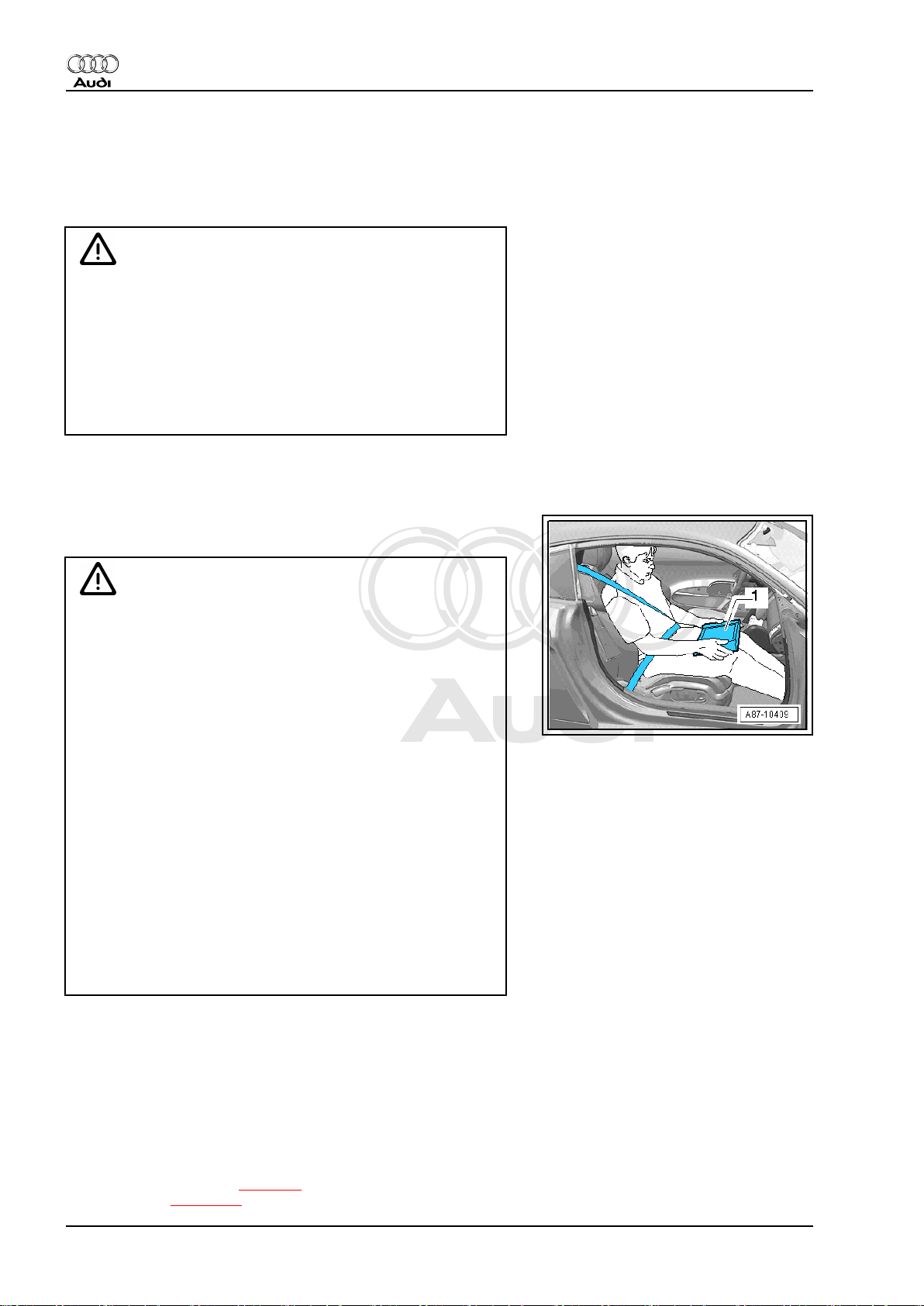
TT Roadster:
♦ Move the passenger's seat back as far as it will go.
♦ Use only vehicle diagnosis and service information sys‐
tem -VAS 5052 A- or diagnosis system -VAS 5053- .
♦ The test equipment -1- must rest flat on the passenger's
thighs (as shown in illustration) and must be operated by
the passenger.
1.4 Removing and installing components from a full or partly full fuel tank
When removing and installing components from a full or partly full
fuel tank, note the following:
♦ Fuel tank must not be full. The amount of fuel which can be
left in the fuel tank is indicated in the corresponding procedure
description. Drain the tank if necessary. Procedure on vehicles
with front-wheel drive ⇒ page 7 , on vehicles with fourwheel drive ⇒ page 40 .
2 Rep. gr.00 - Technical data
Page 7

Protected by copyright. Copying for private or commercial purposes, in part or in whole, is not
permitted unless authorised by AUDI AG. AUDI AG does not guarantee or accept any liability
with respect to the correctness of information in this document. Copyright by AUDI AG.
Fuel supply system, petrol engines - Edition 11.2010
♦ Before commencing work, switch on exhaust extraction sys‐
tem and place an extraction hose close to the sender opening
in the fuel tank to extract escaping petrol fumes. If no exhaust
extraction system is available, a radial fan with a displacement
of at least 15 m3/h can be used (the fan motor must be clear
of the air stream).
♦ Avoid skin contact with fuel. Wear fuel-resistant gloves.
When removing and installing the fuel tank, note the following:
♦ Fuel tank must be empty to reduce weight. Drain the tank if
necessary. Procedure for vehicles in rest-of-world (front-wheel
drive) ⇒ page 7 , vehicles in rest-of-world (four-wheel drive)
⇒ page 40 , USA vehicles (front-wheel drive) ⇒ page 15 ,
USA vehicles (four-wheel drive) ⇒ page 49 .
Audi TT 2007 ➤
1. Safety precautions 3
Page 8
Protected by copyright. Copying for private or commercial purposes, in part or in whole, is not
permitted unless authorised by AUDI AG. AUDI AG does not guarantee or accept any liability
with respect to the correctness of information in this document. Copyright by AUDI AG.
Audi TT 2007 ➤
Fuel supply system, petrol engines - Edition 11.2010
2 General repair instructions
2.1 Rules for cleanliness
Even small amounts of dirt can cause malfunctions. When work‐
ing on the fuel supply system and injection system, pay careful
attention to the following basic rules:
♦ Carefully clean connection points and the surrounding area
with engine cleaner or brake cleaner and dry thoroughly before
opening.
♦ Seal off open pipes/lines and connections immediately with
clean plugs, e.g. from engine bung set -VAS 6122- .
♦ Place parts that have been removed on a clean surface and
cover them over. Do not use fluffy cloths.
♦ Carefully cover or seal open components if repairs cannot be
carried out immediately.
♦ Only install clean components; replacement parts should only
be unpacked immediately prior to installation. Do not use parts
that have been previously unpacked and stored away loose
(e.g. in toolboxes, etc.).
♦ When the system is open: Do not work with compressed air.
Do not move the vehicle unless absolutely necessary.
♦ Protect unplugged electrical connectors against dirt and mois‐
ture and make sure connections are dry when attaching.
2.2 Contact corrosion!
Contact corrosion can occur if unsuitable fasteners are used (e.g.
bolts, nuts, washers, etc.).
For this reason, only fasteners with a special surface coating are
used.
Additionally, all rubber and plastic parts and all adhesives are
made of non-conductive materials.
Always install new parts if you are not sure whether used parts
can be re-fitted ⇒ Electronic parts catalogue .
Note the following:
♦ We recommend using only genuine replacement parts; these
have been tested and are compatible with aluminium.
♦ We recommend the use of Audi accessories.
♦ Damage caused by contact corrosion is not covered under
warranty.
2.3 Test conditions
• Battery voltage at least 12.5 V.
• Fuel pump fuse OK ⇒ Current flow diagrams, Electrical fault
finding and Fitting locations.
• Fuel pump control unit -J538- OK; checking via „Guided Fault
Finding“ ⇒ Vehicle diagnostic, testing and information system
VAS 5051.
• Fuel pump relay -J17- OK ⇒ Current flow diagrams, Electrical
fault finding and Fitting locations.
•
Fuel tank at least 1/4 full.
4 Rep. gr.00 - Technical data
Page 9

Protected by copyright. Copying for private or commercial purposes, in part or in whole, is not
permitted unless authorised by AUDI AG. AUDI AG does not guarantee or accept any liability
with respect to the correctness of information in this document. Copyright by AUDI AG.
• Fuel filter OK.
• Fuel lines OK (not obstructed or crushed).
• Ignition off.
Audi TT 2007 ➤
Fuel supply system, petrol engines - Edition 11.2010
2. General repair instructions 5
Page 10
Protected by copyright. Copying for private or commercial purposes, in part or in whole, is not
permitted unless authorised by AUDI AG. AUDI AG does not guarantee or accept any liability
with respect to the correctness of information in this document. Copyright by AUDI AG.
Audi TT 2007 ➤
Fuel supply system, petrol engines - Edition 11.2010
20 – Fuel supply system
1 Fuel tank with attached components
- rest-of-world vehicles with frontwheel drive
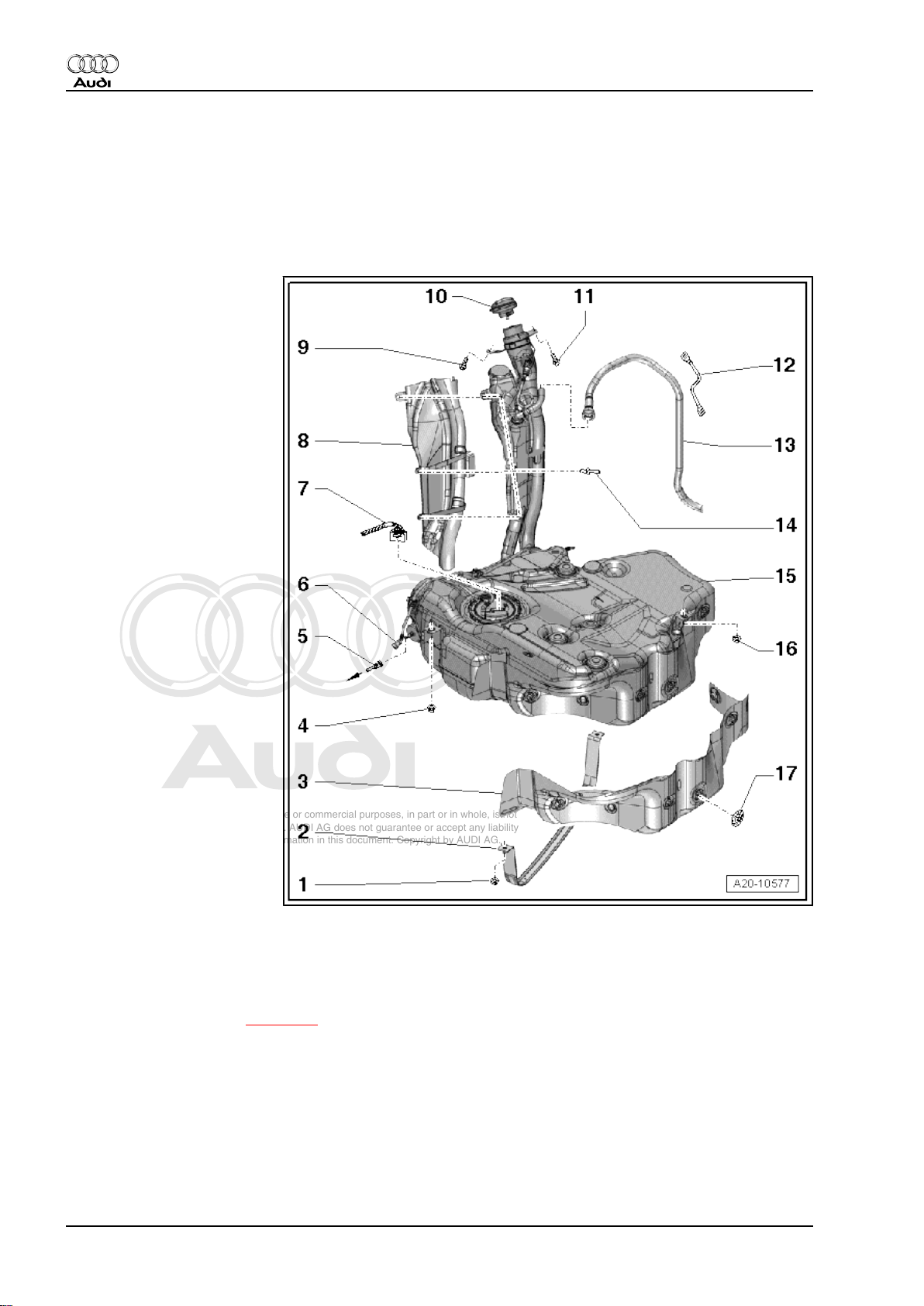
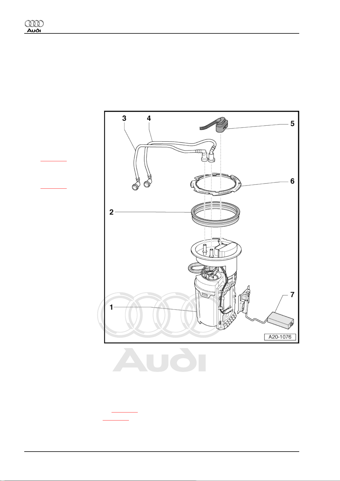
1.1 Fuel tank with attached components - exploded view
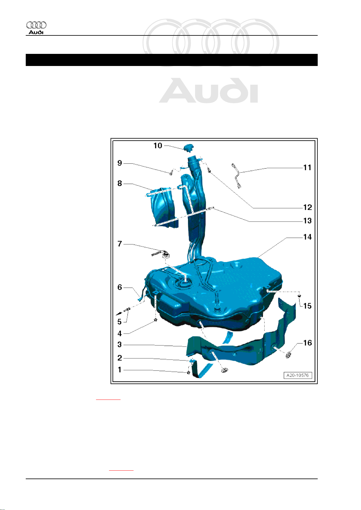
1 - Nut
❑ 20 Nm
2 - Securing strap
❑ Installation position: Fix‐
ing point (hole) points in
direction of travel
3 - Heat shield for fuel tank
4 - Nut
❑ 20 Nm
5 - Fuel line
❑ To engine
❑ Press release tab on
pipe connector to dis‐
connect
6 - Breather line
❑ From fuel filler neck to
activated charcoal filter
❑ Clip onto fuel tank
7 - Electrical connector
❑ For fuel system pressur‐
isation pump -G6- and
fuel gauge sender -G-
8 - Protective plate
❑ For fuel filler neck
9 - Bolt
❑ 11 Nm
10 - Filler cap
❑ Secured to tank flap unit
11 - Earth connection
❑ To eliminate electrostatic charge
❑ Installation position ⇒ page 7
❑ Ensure that connector is seated properly
❑ After installation, use an ohmmeter to check the electrical connection between the protective plate
-item 7- on the fuel filler neck and a bare metal part on the body. Specification: approx. 0 Ω
12 - Bolt
❑ 11 Nm
13 - Pop rivet
14 - Fuel tank
❑ Removing and installing ⇒ page 8
6 Rep. gr.20 - Fuel supply system
Page 11
Protected by copyright. Copying for private or commercial purposes, in part or in whole, is not
permitted unless authorised by AUDI AG. AUDI AG does not guarantee or accept any liability
with respect to the correctness of information in this document. Copyright by AUDI AG.
Fuel supply system, petrol engines - Edition 11.2010
15 - Nut
❑ 20 Nm
16 - Locking washer
❑ Removing: turn anti-clockwise
❑ 3 Nm
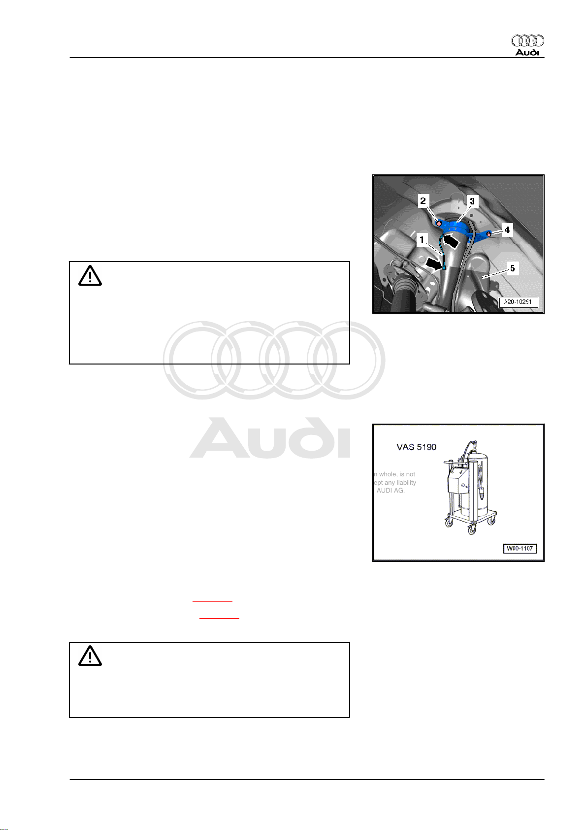
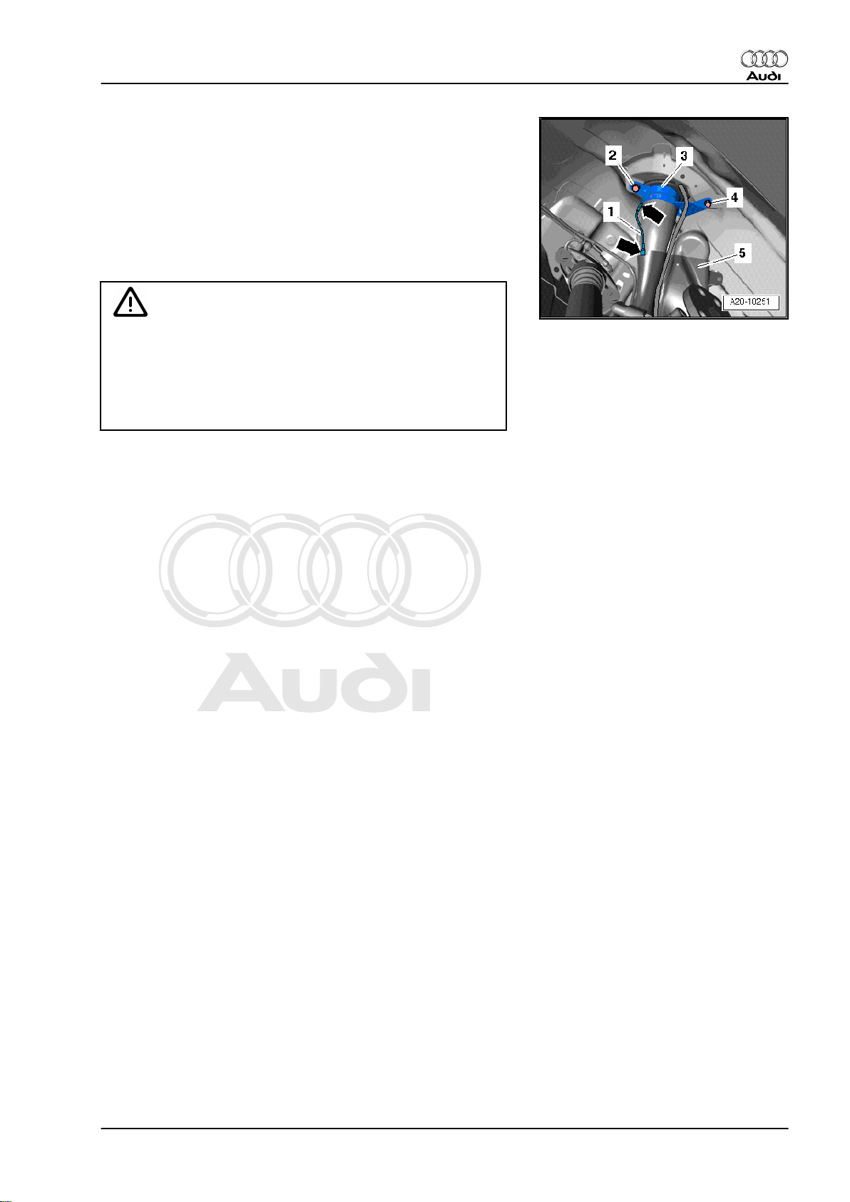
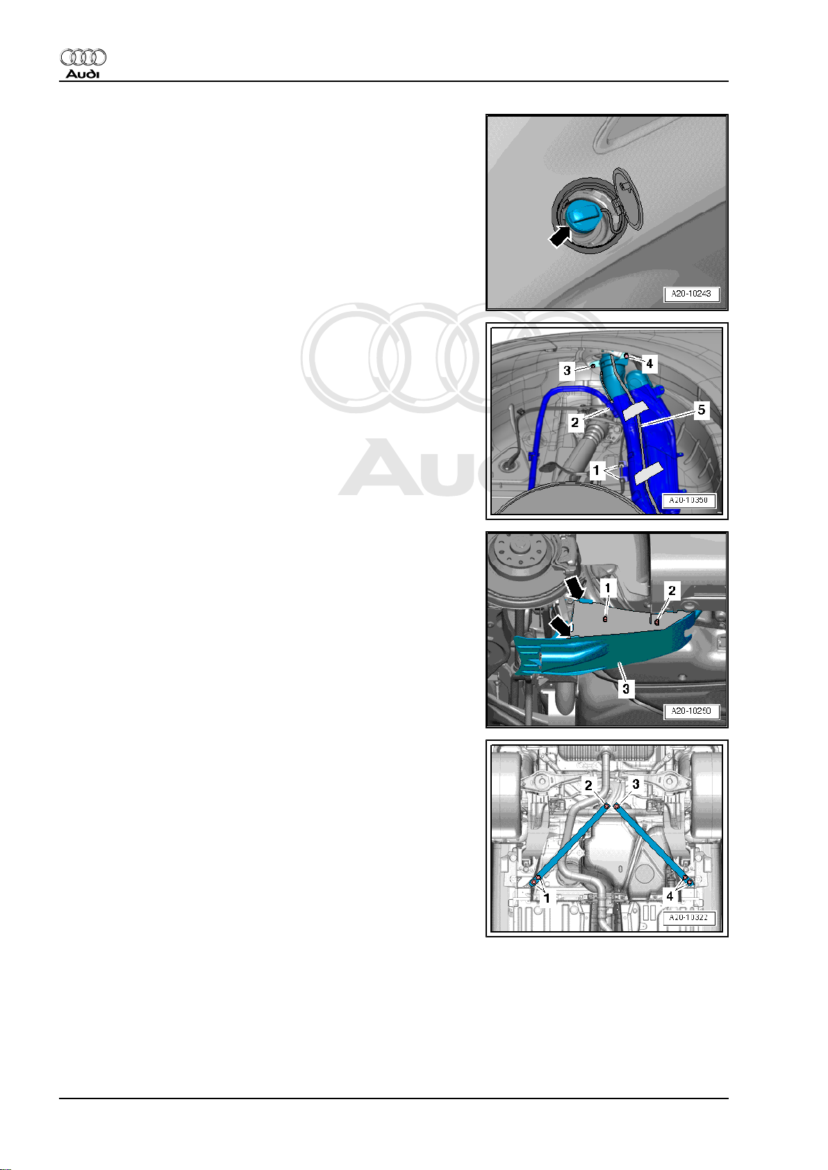
Earth connection for fuel filler neck and protective plate
– The connections -2- and -4- on filler neck must be free from
corrosion to ensure earth connection to body is not impaired.
– Position the earth connection as illustrated -1-.
– Ensure that connectors -arrows- for earth connection are prop‐
erly seated on protective plate -5- and on fuel filler neck -3-.
WARNING
Risk of explosion caused by electrostatic discharge.
♦ After installation, use an ohmmeter to check the electrical
connection between the metal ring on the fuel filler neck
and a bare metal part on the body:
• Specification: approx. 0 Ω.
Audi TT 2007 ➤
1.2 Draining fuel tank
Special tools and workshop equipment required
♦ Fuel extractor -VAS 5190-
Procedure
Observe safety precautions ⇒ page 4 .
Observe rules for cleanliness ⇒ page 4 .
– Release the tank flap.
Caution
To prevent irreparable damage to the electronic components
when disconnecting the battery:
♦ Observe notes on procedure for disconnecting the battery.
1. Fuel tank with attached components - rest-of-world vehicles with front-wheel drive 7
Page 12
Protected by copyright. Copying for private or commercial purposes, in part or in whole, is not
permitted unless authorised by AUDI AG. AUDI AG does not guarantee or accept any liability
with respect to the correctness of information in this document. Copyright by AUDI AG.
Audi TT 2007 ➤
Fuel supply system, petrol engines - Edition 11.2010
– Disconnect battery ⇒ Rep. gr. 27 .
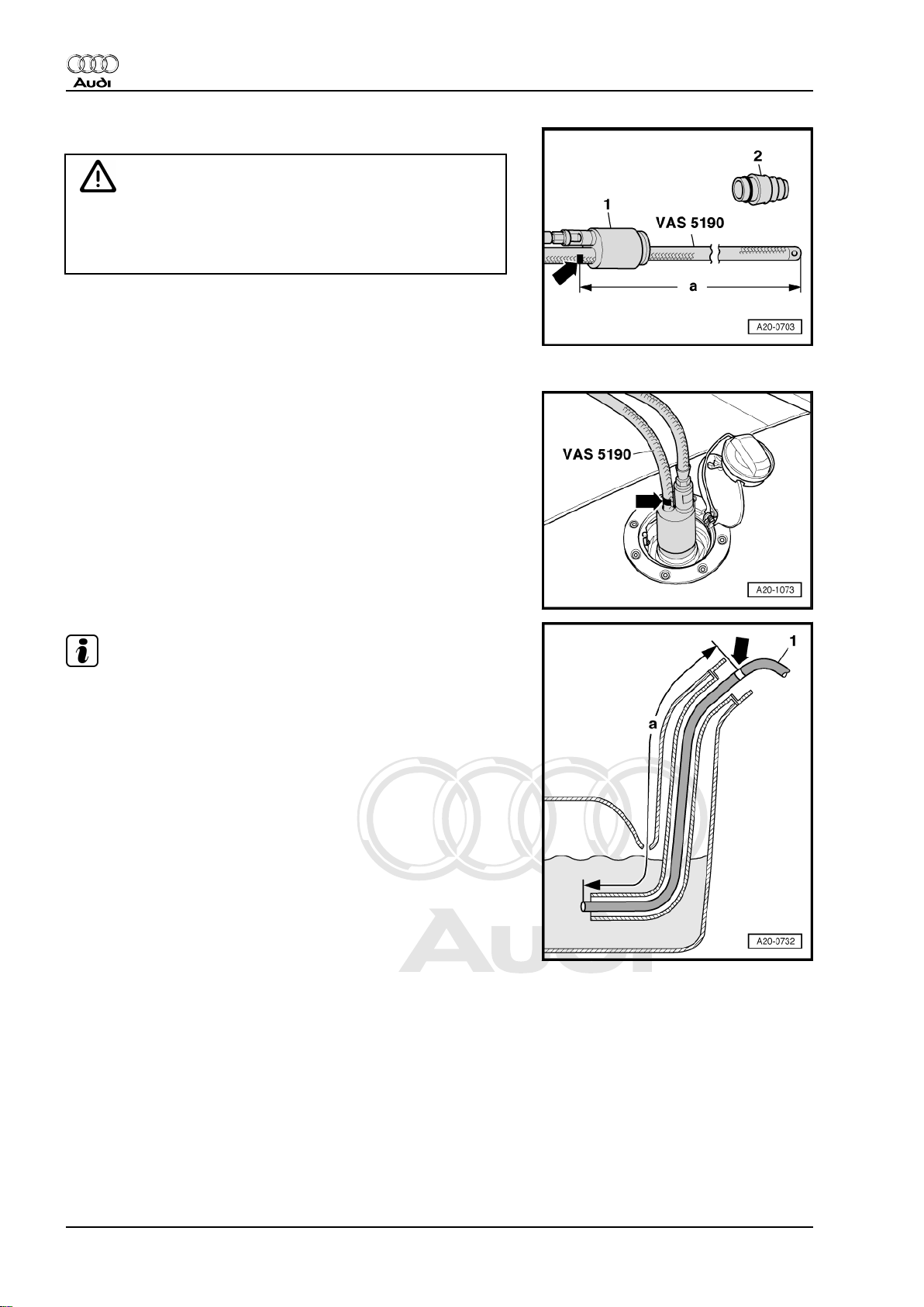
WARNING
Risk of explosion caused by electrostatic discharge.
♦ Secure earth wire of fuel extractor -VAS 5190- to a bare
metal part on the body.
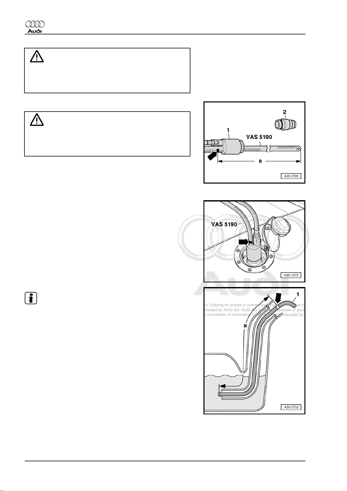
– Detach tapered adapter -2- from shaft end -1- of fuel extractor
-VAS 5190- .
– Use insulating tape to mark the extraction hose -arrow- at a
distance of -a- = 1,370 mm from the end of the hose.
– Remove filler cap from fuel filler neck.
– Screw shaft end of fuel extractor -VAS 5190- onto fuel filler
neck.
– Push extraction hose into fuel tank until marking on hose
-arrow- coincides with shaft end.
Note
♦
The procedure when using a fuel extractor without a shaft end
is fundamentally the same.
♦
In this case, make a mark -arrow- on the extraction hose at
distance -a- = 1,305 mm from the end of the hose using insu‐
lating tape. The extraction hose has been properly inserted
when the affixed mark is level with the edge of the filler neck.
♦
If hose is difficult to insert, apply a thin coat of engine oil. DO
NOT use silicone-based lubricant.
– Drain fuel tank via fuel filler neck.
– Carefully remove extraction hose.
– Connect battery after completing work. Observe notes on pro‐
cedures required after connecting battery ⇒ Rep. gr. 27 .
1.3 Removing and installing fuel tank with attached components
Special tools and workshop equipment required
8 Rep. gr.20 - Fuel supply system
Page 13
Protected by copyright. Copying for private or commercial purposes, in part or in whole, is not
permitted unless authorised by AUDI AG. AUDI AG does not guarantee or accept any liability
with respect to the correctness of information in this document. Copyright by AUDI AG.
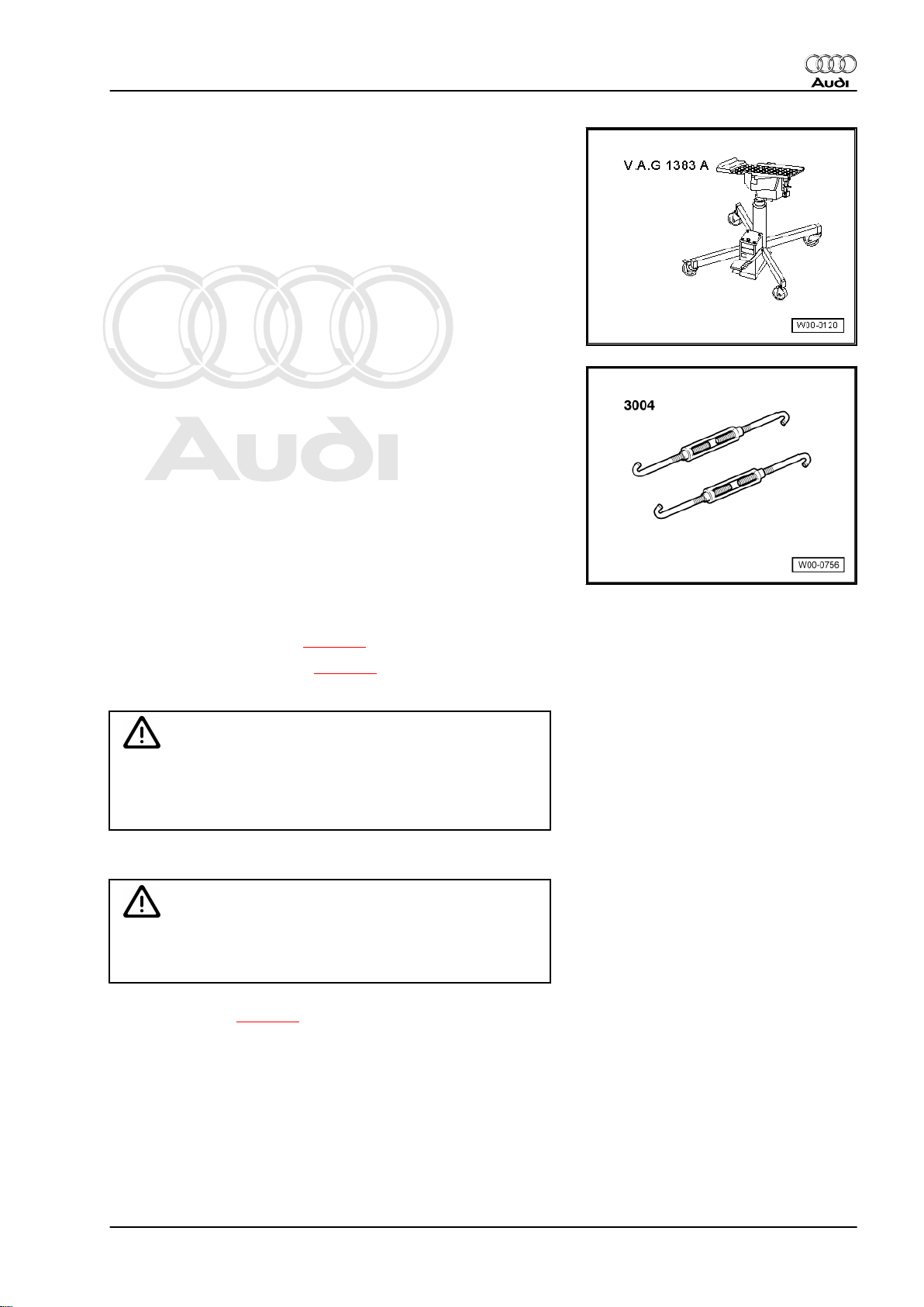
♦ Engine and gearbox jack -V.A.G 1383 A-
♦ Hook -3004-
Audi TT 2007 ➤
Fuel supply system, petrol engines - Edition 11.2010
Removing
Observe safety precautions ⇒ page 4 .
Observe rules for cleanliness ⇒ page 4 .
– Release the tank flap.
Caution
To prevent irreparable damage to the electronic components
when disconnecting the battery:
♦ Observe notes on procedure for disconnecting the battery.
– Disconnect battery ⇒ Rep. gr. 27 .
WARNING
Risk of accident caused by weight of fuel tank
♦ Fuel tank must be empty when it is removed.
– Drain fuel tank ⇒ page 7 .
1. Fuel tank with attached components - rest-of-world vehicles with front-wheel drive 9
Page 14
Protected by copyright. Copying for private or commercial purposes, in part or in whole, is not
permitted unless authorised by AUDI AG. AUDI AG does not guarantee or accept any liability
with respect to the correctness of information in this document. Copyright by AUDI AG.
Audi TT 2007 ➤
Fuel supply system, petrol engines - Edition 11.2010
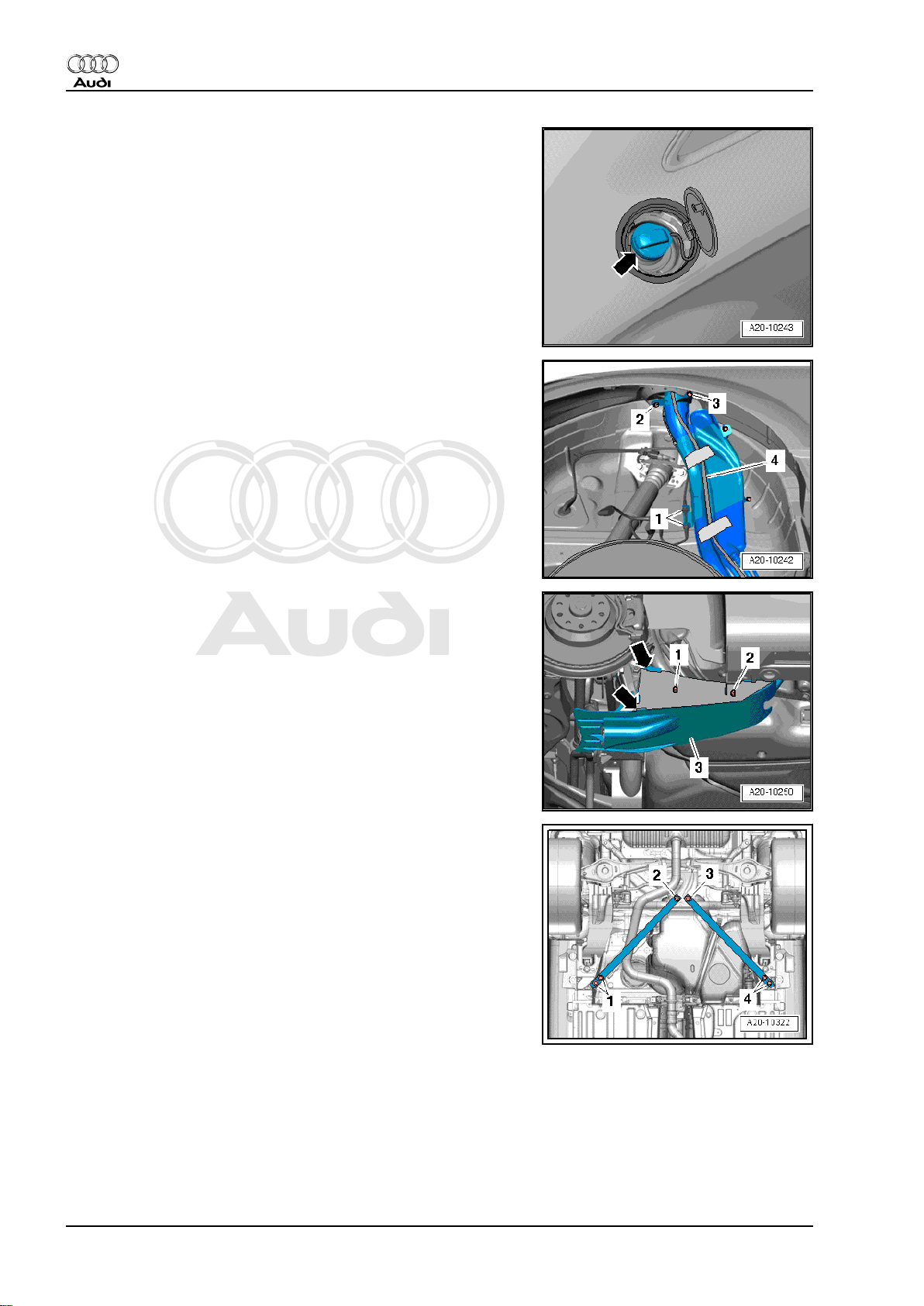
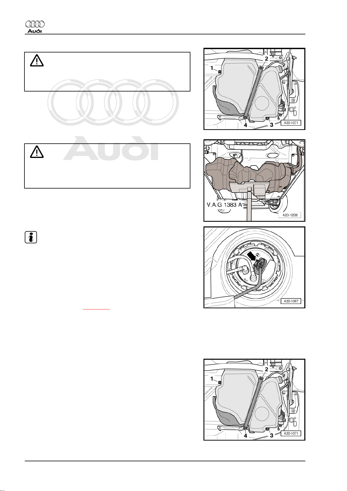
– Clean area around fuel filler neck.
– Remove filler cap -arrow- from fuel filler neck.
– Seal opening of fuel filler neck with a piece of clean foam or
similar to prevent dirt from dropping into the tank.
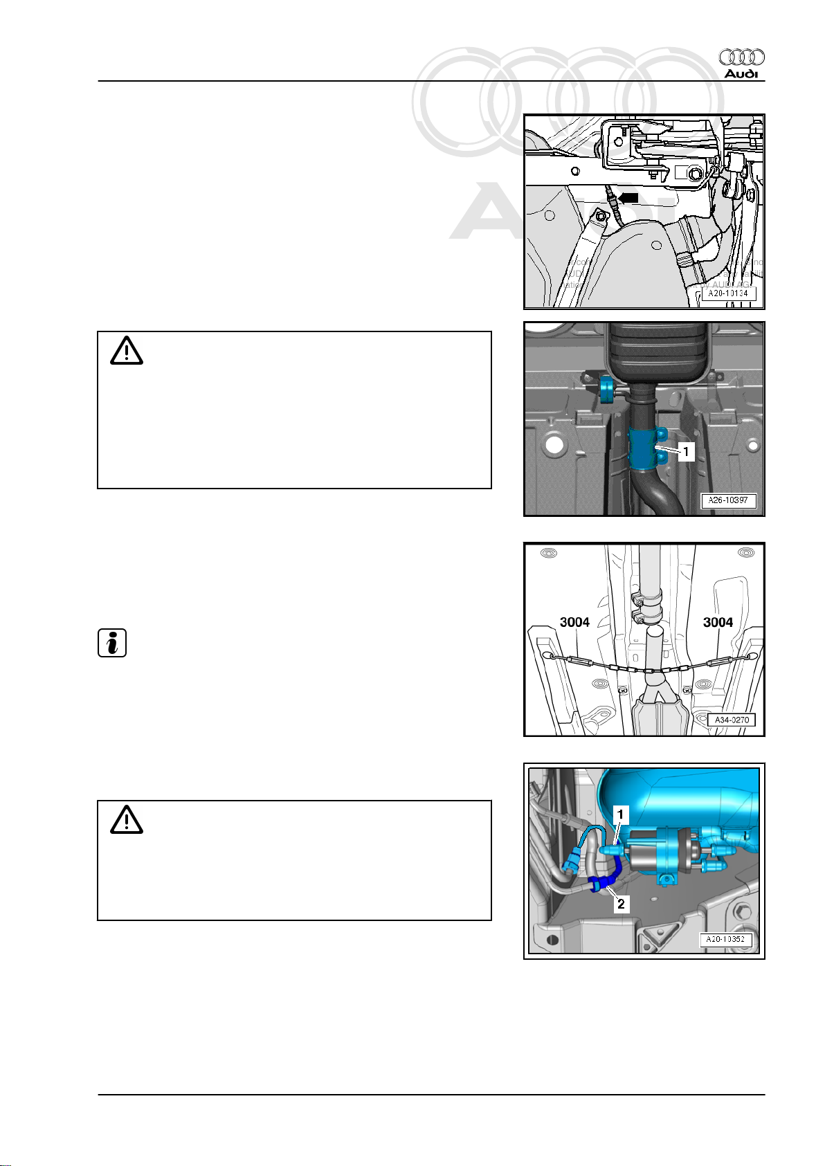
– Remove rear right wheel housing liner ⇒ Rep. gr. 66 .
– Detach electrical wire -1- for ABS speed sensor from bracket
on fuel filler neck.
– Remove bolts -2- and -3- for fuel filler neck.
– Move overflow hose -4- on fuel filler neck clear.
– Pull out spreader pins -1- and -2-.
– Disengage stone deflector -3- on trailing arm (right-side)
-arrows- and remove.
TT Roadster:
– Remove bolts -1 ... 4- and detach diagonal struts.
10 Rep. gr.20 - Fuel supply system
Page 15
Protected by copyright. Copying for private or commercial purposes, in part or in whole, is not
permitted unless authorised by AUDI AG. AUDI AG does not guarantee or accept any liability
with respect to the correctness of information in this document. Copyright by AUDI AG.
Fuel supply system, petrol engines - Edition 11.2010
All vehicles (continued):
Caution
Risk of damage to flexible joints in front exhaust pipe
♦ The flexible joints in the front exhaust pipe must not be
bent more than 10°.
♦ Before slackening clamp on exhaust pipe, secure front
section of exhaust system to underbody of vehicle with a
chain.
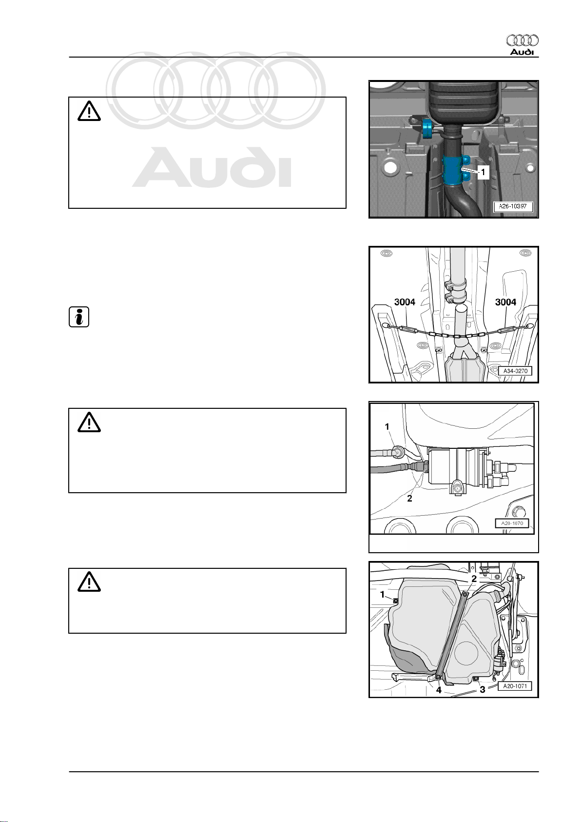
– Disconnect exhaust system at clamp -1-.
– Secure front section of exhaust system with a chain. To do so,
engage hooks -3004- into openings on underside of vehicle
(remove plugs if fitted).
– Push the clamp back in order to separate the exhaust system.
Note
Audi TT 2007 ➤
A second person will be required for detaching rear section of
exhaust system.
– Disengage rear silencer at the rubber mountings and remove
rear section of exhaust system.
WARNING
Risk of injury - fuel system operates under high pressure.
♦ To reduce the pressure in the fuel system, wrap a clean
cloth around the connection and carefully loosen the con‐
nection.
– Disconnect fuel line -2- and breather line -1- from front right of
fuel tank by pressing release tabs.
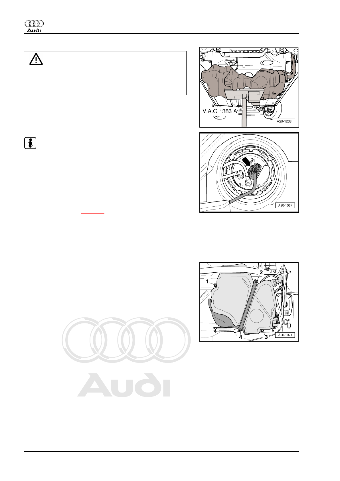
WARNING
Risk of accident caused by weight of fuel tank
♦ Fuel tank must be empty when it is removed.
– First unscrew bolts -1- and -3-.
– Position engine and gearbox jack -V.A.G 1383 A- below vehi‐
cle to support tank.
– Remove bolts -2- and -4-.
1. Fuel tank with attached components - rest-of-world vehicles with front-wheel drive 11
Page 16
Protected by copyright. Copying for private or commercial purposes, in part or in whole, is not
permitted unless authorised by AUDI AG. AUDI AG does not guarantee or accept any liability
with respect to the correctness of information in this document. Copyright by AUDI AG.
Audi TT 2007 ➤
Fuel supply system, petrol engines - Edition 11.2010
Caution
Risk of overstretching electrical wiring.
♦ Subsequently, when lowering fuel tank, make sure that
electrical wiring is not under tension.
– Lower fuel tank using engine and gearbox jack -V.A.G 1383
A- only until you can reach electrical connector on flange with
your hand.
Note
Illustration shows electrical connector on flange in installation po‐
sition.
– Unplug electrical connector -arrow- at flange.
– Remove fuel tank downwards (turning it sideways as re‐
quired).
Installing
• Tightening torques ⇒ page 6
Installation is carried out in the reverse order; note the following:
– Position fuel tank with securing strap on underbody, using en‐
gine and gearbox jack -V.A.G 1383 A- .
– When installing fuel tank, make sure that the fuel filler neck is
correctly inserted into the opening on the body.
– Secure fuel tank by first tightening bolts at points -2- and -4-,
then at points -1- and -3-.
12 Rep. gr.20 - Fuel supply system
Page 17
Protected by copyright. Copying for private or commercial purposes, in part or in whole, is not
permitted unless authorised by AUDI AG. AUDI AG does not guarantee or accept any liability
with respect to the correctness of information in this document. Copyright by AUDI AG.
Fuel supply system, petrol engines - Edition 11.2010
– The connections -2- and -4- on filler neck must be free from
corrosion to ensure earth connection to body is not impaired.
– Tighten bolts -2- and -4- for fuel filler neck.
– Check the earth wiring at both ends for traces of oxidation and
remove oxidation if necessary.
– Position the earth connection as illustrated -1-.
– Ensure that connectors -arrows- for earth connection are prop‐
erly seated on protective plate -5- and on fuel filler neck -3-.
WARNING
Risk of explosion caused by electrostatic discharge.
♦ After installation, use an ohmmeter to check the electrical
connection between the metal ring on the fuel filler neck
and a bare metal part on the body:
• Specification: approx. 0 Ω.
– Attach electrical wire for ABS speed sensor to bracket on fuel
filler neck.
– Install rear section of exhaust system ⇒ Rep. gr. 26 .
– Install rear right wheel housing liner ⇒ Rep. gr. 66. .
TT Roadster:
– Install diagonal struts ⇒ Rep. gr. 42 .
All vehicles (continued):
– Connect battery. Observe notes on procedures required after
connecting battery ⇒ Rep. gr. 27 .
Audi TT 2007 ➤
1. Fuel tank with attached components - rest-of-world vehicles with front-wheel drive 13
Page 18
Protected by copyright. Copying for private or commercial purposes, in part or in whole, is not
permitted unless authorised by AUDI AG. AUDI AG does not guarantee or accept any liability
with respect to the correctness of information in this document. Copyright by AUDI AG.
Audi TT 2007 ➤
Fuel supply system, petrol engines - Edition 11.2010
2 Fuel tank with attached components
- USA vehicles with front-wheel drive
2.1 Fuel tank with attached components - exploded view
1 - Nut
❑ 20 Nm
2 - Securing strap
❑ Installation position: Fix‐
ing point (hole) points in
direction of travel
3 - Heat shield for fuel tank
4 - Nut
❑ 20 Nm
5 - Fuel line
❑ To engine
❑ Press release tab on
pipe connector to dis‐
connect
6 - Breather line
❑ From activated charcoal
filter to activated char‐
coal filter solenoid
valve 1 -N80-
❑ Clip onto fuel tank
7 - Electrical connector
❑ For fuel system pressur‐
isation pump -G6- and
fuel gauge sender -G-
8 - Protective plate
❑ For fuel filler neck
9 - Bolt
❑ 11 Nm
10 - Filler cap
❑ Secured to tank flap unit
11 - Bolt
❑ 11 Nm
12 - Earth connection
❑ To eliminate electrostatic charge
❑ Installation position ⇒ page 15
❑ Ensure that connector is seated properly
❑ After installation, use an ohmmeter to check the electrical connection between the protective plate
-item 7- on the fuel filler neck and a bare metal part on the body. Specification: approx. 0 Ω
13 - Breather line
❑ From gravity valve to activated charcoal filter
❑ Clip onto bracket in wheel housing
❑ Press release tab on pipe connector to disconnect
14 Rep. gr.20 - Fuel supply system
Page 19
Protected by copyright. Copying for private or commercial purposes, in part or in whole, is not
permitted unless authorised by AUDI AG. AUDI AG does not guarantee or accept any liability
with respect to the correctness of information in this document. Copyright by AUDI AG.
Fuel supply system, petrol engines - Edition 11.2010
14 - Pop rivet
15 - Fuel tank
❑ Removing and installing ⇒ page 16
16 - Nut
❑ 20 Nm
17 - Locking washer
❑ Removing: turn anti-clockwise
❑ 3 Nm
Earth connection for fuel filler neck and protective plate
– The connections -2- and -4- on filler neck must be free from
corrosion to ensure earth connection to body is not impaired.
– Position the earth connection as illustrated -1-.
– Ensure that connectors -arrows- for earth connection are prop‐
erly seated on protective plate -5- and on fuel filler neck -3-.
WARNING
Audi TT 2007 ➤
Risk of explosion caused by electrostatic discharge.
♦ After installation, use an ohmmeter to check the electrical
connection between the metal ring on the fuel filler neck
and a bare metal part on the body:
• Specification: approx. 0 Ω.
2.2 Draining fuel tank
Special tools and workshop equipment required
♦ Fuel extractor -VAS 5190-
Procedure
Observe safety precautions ⇒ page 4 .
Observe rules for cleanliness ⇒ page 4 .
– Release the tank flap.
2. Fuel tank with attached components - USA vehicles with front-wheel drive 15
Page 20
Protected by copyright. Copying for private or commercial purposes, in part or in whole, is not
permitted unless authorised by AUDI AG. AUDI AG does not guarantee or accept any liability
with respect to the correctness of information in this document. Copyright by AUDI AG.
Audi TT 2007 ➤
Fuel supply system, petrol engines - Edition 11.2010
Caution
To prevent irreparable damage to the electronic components
when disconnecting the battery:
♦ Observe notes on procedure for disconnecting the battery.
– Disconnect battery ⇒ Rep. gr. 27 .
WARNING
Risk of explosion caused by electrostatic discharge.
♦ Secure earth wire of fuel extractor -VAS 5190- to a bare
metal part on the body.
– Detach tapered adapter -2- from shaft end -1- of fuel extractor
-VAS 5190- .
– Use insulating tape to mark the extraction hose -arrow- at a
distance of -a- = 1,370 mm from the end of the hose.
– Remove filler cap from fuel filler neck.
– Screw shaft end of fuel extractor -VAS 5190- onto fuel filler
neck.
– Push extraction hose into fuel tank until marking on hose
-arrow- coincides with shaft end.
Note
♦
The procedure when using a fuel extractor without a shaft end
is fundamentally the same.
♦
In this case, make a mark -arrow- on the extraction hose at
distance -a- = 1,305 mm from the end of the hose using insu‐
lating tape. The extraction hose has been properly inserted
when the affixed mark is level with the edge of the filler neck.
♦
If hose is difficult to insert, apply a thin coat of engine oil. DO
NOT use silicone-based lubricant.
– Drain fuel tank via fuel filler neck.
– Carefully remove extraction hose.
– Connect battery after completing work. Observe notes on pro‐
cedures required after connecting battery ⇒ Rep. gr. 27 .
2.3 Removing and installing fuel tank with attached components
Special tools and workshop equipment required
16 Rep. gr.20 - Fuel supply system
Page 21

Protected by copyright. Copying for private or commercial purposes, in part or in whole, is not
permitted unless authorised by AUDI AG. AUDI AG does not guarantee or accept any liability
with respect to the correctness of information in this document. Copyright by AUDI AG.
♦ Engine and gearbox jack -V.A.G 1383 A-
♦ Hook -3004-
Audi TT 2007 ➤
Fuel supply system, petrol engines - Edition 11.2010
Removing
Observe safety precautions ⇒ page 4 .
Observe rules for cleanliness ⇒ page 4 .
– Release the tank flap.
Caution
To prevent irreparable damage to the electronic components
when disconnecting the battery:
♦ Observe notes on procedure for disconnecting the battery.
– Disconnect battery ⇒ Rep. gr. 27 .
WARNING
Risk of accident caused by weight of fuel tank
♦ Fuel tank must be empty when it is removed.
– Drain fuel tank ⇒ page 15 .
2. Fuel tank with attached components - USA vehicles with front-wheel drive 17
Page 22
Protected by copyright. Copying for private or commercial purposes, in part or in whole, is not
permitted unless authorised by AUDI AG. AUDI AG does not guarantee or accept any liability
with respect to the correctness of information in this document. Copyright by AUDI AG.
Audi TT 2007 ➤
Fuel supply system, petrol engines - Edition 11.2010
– Clean area around fuel filler neck.
– Remove filler cap -arrow- from fuel filler neck.
– Seal opening of fuel filler neck with a piece of clean foam or
similar to prevent dirt from dropping into the tank.
– Remove rear right wheel housing liner ⇒ Rep. gr. 66 .
– Remove bolts -3- and -4- for fuel filler neck.
– Remove breather line -2- going to activated charcoal filter
(press release tab).
– Detach electrical wire -1- for ABS speed sensor from bracket
on fuel filler neck.
– Move overflow hose -5- on fuel filler neck clear.
– Pull out spreader pins -1- and -2-.
– Disengage stone deflector -3- on trailing arm (right-side)
-arrows- and remove.
TT Roadster:
– Remove bolts -1 ... 4- and detach diagonal struts.
18 Rep. gr.20 - Fuel supply system
Page 23
Protected by copyright. Copying for private or commercial purposes, in part or in whole, is not
permitted unless authorised by AUDI AG. AUDI AG does not guarantee or accept any liability
with respect to the correctness of information in this document. Copyright by AUDI AG.
Fuel supply system, petrol engines - Edition 11.2010
All vehicles (continued):
– Press release tab and disconnect breather line -arrow- leading
to activated charcoal filter.
Caution
Risk of damage to flexible joints in front exhaust pipe
♦ The flexible joints in the front exhaust pipe must not be
bent more than 10°.
♦ Before slackening clamp on exhaust pipe, secure front
section of exhaust system to underbody of vehicle with a
chain.
Audi TT 2007 ➤
– Disconnect exhaust system at clamp -1-.
– Secure front section of exhaust system with a chain. To do so,
engage hooks -3004- into openings on underside of vehicle
(remove plugs if fitted).
– Push the clamp back in order to separate the exhaust system.
Note
A second person will be required for detaching rear section of
exhaust system.
– Disengage rear silencer at the rubber mountings and remove
rear section of exhaust system.
– Press release tab and disconnect breather line -2- at front right
of fuel tank.
WARNING
Risk of injury - fuel system operates under high pressure.
♦ To reduce the pressure in the fuel system, wrap a clean
cloth around the connection and carefully loosen the con‐
nection.
– Press release tabs and disconnect fuel line -1- at front right of
fuel tank.
2. Fuel tank with attached components - USA vehicles with front-wheel drive 19
Page 24
Protected by copyright. Copying for private or commercial purposes, in part or in whole, is not
permitted unless authorised by AUDI AG. AUDI AG does not guarantee or accept any liability
with respect to the correctness of information in this document. Copyright by AUDI AG.
Audi TT 2007 ➤
Fuel supply system, petrol engines - Edition 11.2010
WARNING
Risk of accident caused by weight of fuel tank
♦ Fuel tank must be empty when it is removed.
– First unscrew bolts -1- and -3-.
– Position engine and gearbox jack -V.A.G 1383 A- below vehi‐
cle to support tank.
– Remove bolts -2- and -4-.
Caution
Risk of overstretching electrical wiring.
♦ Subsequently, when lowering fuel tank, make sure that
electrical wiring is not under tension.
– Lower fuel tank using engine and gearbox jack -V.A.G 1383
A- only until you can reach electrical connector on flange with
your hand.
Note
Illustration shows electrical connector on flange in installation po‐
sition.
– Unplug electrical connector -arrow- at flange.
– Remove fuel tank downwards (turning it sideways as re‐
quired).
Installing
• Tightening torques ⇒ page 14
Installation is carried out in the reverse order; note the following:
– Position fuel tank with securing strap on underbody, using en‐
gine and gearbox jack -V.A.G 1383 A- .
– When installing fuel tank, make sure that the fuel filler neck is
correctly inserted into the opening on the body.
– Secure fuel tank by first tightening bolts at points -2- and -4-,
then at points -1- and -3-.
20 Rep. gr.20 - Fuel supply system
Page 25
Protected by copyright. Copying for private or commercial purposes, in part or in whole, is not
permitted unless authorised by AUDI AG. AUDI AG does not guarantee or accept any liability
with respect to the correctness of information in this document. Copyright by AUDI AG.
Fuel supply system, petrol engines - Edition 11.2010
– The connections -2- and -4- on filler neck must be free from
corrosion to ensure earth connection to body is not impaired.
– Tighten bolts -2- and -4- for fuel filler neck.
– Check the earth wiring at both ends for traces of oxidation and
remove oxidation if necessary.
– Position the earth connection as illustrated -1-.
– Ensure that connectors -arrows- for earth connection are prop‐
erly seated on protective plate -5- and on fuel filler neck -3-.
WARNING
Risk of explosion caused by electrostatic discharge.
♦ After installation, use an ohmmeter to check the electrical
connection between the metal ring on the fuel filler neck
and a bare metal part on the body:
• Specification: approx. 0 Ω.
– Attach electrical wire for ABS speed sensor to bracket on fuel
filler neck.
– Install breather line (leading to activated charcoal filter) at filler
neck.
– Install rear section of exhaust system ⇒ Rep. gr. 26 .
– Install rear right wheel housing liner ⇒ Rep. gr. 66. .
TT Roadster:
– Install diagonal struts ⇒ Rep. gr. 42 .
All vehicles (continued):
– Connect battery. Observe notes on procedures required after
connecting battery ⇒ Rep. gr. 27 .
Audi TT 2007 ➤
2. Fuel tank with attached components - USA vehicles with front-wheel drive 21
Page 26
Protected by copyright. Copying for private or commercial purposes, in part or in whole, is not
permitted unless authorised by AUDI AG. AUDI AG does not guarantee or accept any liability
with respect to the correctness of information in this document. Copyright by AUDI AG.
Audi TT 2007 ➤
Fuel supply system, petrol engines - Edition 11.2010
3 Fuel delivery unit and fuel gauge
sender - all vehicles with front-wheel
drive
3.1 Fuel delivery unit and fuel gauge sender - exploded view
1 - Fuel delivery unit
❑ Different versions avail‐
able ⇒ Electronic parts
catalogue
❑ Checking fuel pump
(electrical test) - vehi‐
cles with TFSI engine
⇒ page 23
❑ Checking residual pres‐
sure ⇒ Rep. gr. 24
❑ Removing and installing
⇒ page 30
❑ Put at least 5 litres of
fuel into tank after instal‐
ling
2 - Seal
❑ Renew
❑ Install dry
3 - Fuel supply line
❑ To fuel filter
❑ Do not kink
❑ Attached to connection
marked „V“ on flange
❑ To disconnect from
flange, press release
tab on connection
4 - Fuel return line
❑ Do not kink
❑ Attached to connection
marked „R“ on flange
❑ To disconnect from
flange, press release
tab on connection
5 - Electrical connector
❑ For fuel system pressurisation pump -G6- and fuel gauge sender -G-
6 - Locking ring
❑ Remove and install using wrench -T10202❑ 110 Nm
7 - Fuel gauge sender -G-
❑ Different versions available ⇒ Electronic parts catalogue
❑ Checking resistance values ⇒ page 34
❑ Removing and installing ⇒ page 36
22 Rep. gr.20 - Fuel supply system
Page 27
Protected by copyright. Copying for private or commercial purposes, in part or in whole, is not
permitted unless authorised by AUDI AG. AUDI AG does not guarantee or accept any liability
with respect to the correctness of information in this document. Copyright by AUDI AG.
Fuel supply system, petrol engines - Edition 11.2010
3.2 Checking fuel pump (electrical test) - ve‐
hicles with TFSI engine
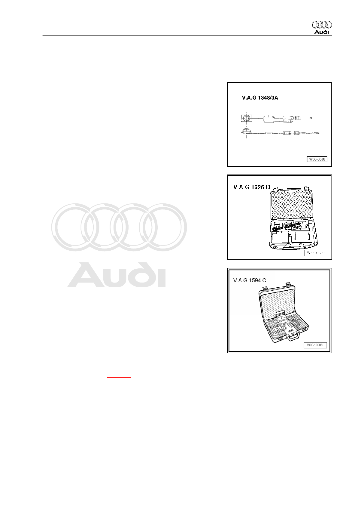
Special tools and workshop equipment required
♦ Remote control -V.A.G 1348/3A- for V.A.G 1348 with adapter
cable -V.A.G 1348/3-2-
♦ Hand-held multimeter -V.A.G 1526D-
Audi TT 2007 ➤
♦ Auxiliary measuring set -V.A.G 1594C-
Procedure
Observe test conditions ⇒ page 4 .
TT Coupé:
– Remove rear seat bench ⇒ Rep. gr. 72 .
TT Roadster:
– Remove back panel side trim (right-side) ⇒ Rep. gr. 70 .
3. Fuel delivery unit and fuel gauge sender - all vehicles with front-wheel drive 23
Page 28
Protected by copyright. Copying for private or commercial purposes, in part or in whole, is not
permitted unless authorised by AUDI AG. AUDI AG does not guarantee or accept any liability
with respect to the correctness of information in this document. Copyright by AUDI AG.
Audi TT 2007 ➤
Fuel supply system, petrol engines - Edition 11.2010
All vehicles (continued):
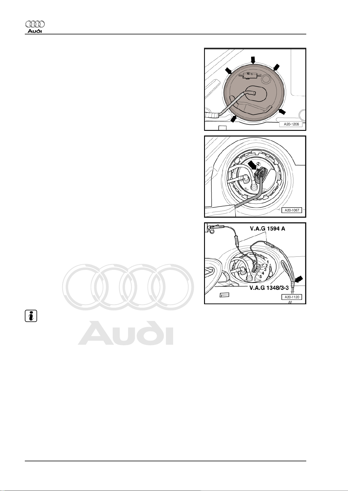
– Unclip retaining tabs -arrows- for flange cover.
– Unplug electrical connector -arrow- at flange.
– Connect remote control -V.A.G 1348/3A- for V.A.G 1348 to
contact -1- using adapter cable -V.A.G 1348/3-3- and test lead
from auxiliary measuring set -V.A.G 1594C- .
– Tape off 2nd connector contact of adapter cable -V.A.G
1348/3-3- with insulating tape -arrow- to prevent short circuits.
– Connect contact -5- to the body (earth) using a test lead from
auxiliary measuring set -V.A.G 1594C- .
– Connect crocodile clip to battery „+“.
– Press remote control button.
• Pump should start running audibly.
Note
The fuel pump runs very quietly. Where possible, avoid noisy sur‐
roundings for this test.
24 Rep. gr.20 - Fuel supply system
Page 29
Protected by copyright. Copying for private or commercial purposes, in part or in whole, is not
permitted unless authorised by AUDI AG. AUDI AG does not guarantee or accept any liability
with respect to the correctness of information in this document. Copyright by AUDI AG.
Fuel supply system, petrol engines - Edition 11.2010
If no noise can be heard from pump:
– Remove fuel delivery unit ⇒ page 30 .
– Check that the electrical wires between flange and fuel pump
are connected and test for continuity.
If no faults are found in the wiring:
– Fuel pump is defective. Renew fuel delivery unit.
Installation is carried out in the reverse order; note the following:
TT Roadster:
– Install back panel side trim (right-side) ⇒ Rep. gr. 70 .
TT Coupé:
– Install rear seat bench ⇒ Rep. gr. 72 .
3.3 Checking fuel pump control unit -J538- vehicles with TFSI engine
Audi TT 2007 ➤
♦ On vehicles with TFSI engine, voltage for the fuel pump is
supplied via fuel pump control unit -J538- .
♦ Check fuel pump control unit -J538- in „Guided Fault Finding“
⇒ Vehicle diagnostic, testing and information system
VAS 5051.
3.4 Removing and installing fuel pump con‐
trol unit -J538- - vehicles with TFSI en‐
gine
Removing
TT Coupé:
– Remove rear seat bench ⇒ Rep. gr. 72 .
TT Roadster:
– Remove back panel side trim (right-side) ⇒ Rep. gr. 70 .
All vehicles (continued):
– Remove fuel pump control unit -J538- from cover for flange
and unplug electrical connector -arrow-.
3. Fuel delivery unit and fuel gauge sender - all vehicles with front-wheel drive 25
Page 30
Protected by copyright. Copying for private or commercial purposes, in part or in whole, is not
permitted unless authorised by AUDI AG. AUDI AG does not guarantee or accept any liability
with respect to the correctness of information in this document. Copyright by AUDI AG.
Audi TT 2007 ➤
Fuel supply system, petrol engines - Edition 11.2010
– Unclip the retaining tabs -arrows- for the flange cover (right-
side).
– Unplug electrical connector -arrow- at flange.
Installing
Installation is carried out in the reverse order; note the following:
TT Coupé:
– Install rear seat bench ⇒ Rep. gr. 72 .
TT Roadster:
– Install back panel side trim (right-side) ⇒ Rep. gr. 70 .
26 Rep. gr.20 - Fuel supply system
Page 31

Protected by copyright. Copying for private or commercial purposes, in part or in whole, is not
permitted unless authorised by AUDI AG. AUDI AG does not guarantee or accept any liability
with respect to the correctness of information in this document. Copyright by AUDI AG.
Audi TT 2007 ➤
Fuel supply system, petrol engines - Edition 11.2010
3.5 Checking fuel pump delivery rate - vehicles with TFSI engine
Special tools and workshop
equipment required
♦ K-Jetronic pressure tester -
V.A.G 1318-
♦ Adapter -V.A.G 1318/11-
♦ Adapter -V.A.G
1318/17-1A-
♦ Connector -V.A.G 1318/23-
♦ Remote control -V.A.G
1348/3A- for V.A.G 1348
with adapter cable -V.A.G
1348/3-3-
♦ Auxiliary measuring set -
V.A.G 1594C-
♦ Fuel-resistant measuring
container
Procedure
Observe test conditions ⇒ page 4 .
TT Coupé:
– Remove rear seat bench ⇒ Rep. gr. 72 .
TT Roadster:
– Remove back panel side trim (right-side) ⇒ Rep. gr. 70 .
3. Fuel delivery unit and fuel gauge sender - all vehicles with front-wheel drive 27
Page 32

Protected by copyright. Copying for private or commercial purposes, in part or in whole, is not
permitted unless authorised by AUDI AG. AUDI AG does not guarantee or accept any liability
with respect to the correctness of information in this document. Copyright by AUDI AG.
Audi TT 2007 ➤
Fuel supply system, petrol engines - Edition 11.2010
All vehicles (continued):
– Unclip retaining tabs -arrows- for flange cover.
– Unplug electrical connector -arrow- at flange.
– Connect remote control -V.A.G 1348/3A- for V.A.G 1348 to
contact -1- using adapter cable -V.A.G 1348/3-3- and test lead
from auxiliary measuring set -V.A.G 1594C- .
– Tape off 2nd connector contact of adapter cable -V.A.G
1348/3-3- with insulating tape -arrow- to prevent short circuits.
– Connect contact -5- to the body (earth) using a test lead from
auxiliary measuring set -V.A.G 1594C- .
– Connect crocodile clip to battery „+“ (positive terminal in en‐
gine compartment).
– Remove filler cap from fuel filler neck.
Rest-of-world vehicles with toothed belt drive:
– Detach fuel line from retainer and remove heat insulation
sleeve at fuel line connection.
WARNING
Risk of injury - fuel system operates under high pressure.
♦ To reduce the pressure in the fuel system, wrap a clean
cloth around the connection and carefully loosen the con‐
nection.
– Pull release ring and disconnect fuel line -arrow-.
28 Rep. gr.20 - Fuel supply system
Page 33

Protected by copyright. Copying for private or commercial purposes, in part or in whole, is not
permitted unless authorised by AUDI AG. AUDI AG does not guarantee or accept any liability
with respect to the correctness of information in this document. Copyright by AUDI AG.
Fuel supply system, petrol engines - Edition 11.2010
USA vehicles with toothed belt drive:
– Detach fuel line from retainer and remove heat insulation
sleeve -1- at fuel line connection.
WARNING
Risk of injury - fuel system operates under high pressure.
♦ To reduce the pressure in the fuel system, wrap a clean
cloth around the connection and carefully loosen the con‐
nection.
– Pull release ring and disconnect fuel line -arrow-.
Vehicles with timing chain:
– Push down protective sleeve -1- and disconnect fuel line.
– First press hose connector -2- downwards -arrow A-, then
press release tabs -arrow B-.
– Pull off hose connector, keeping release tabs depressed.
Audi TT 2007 ➤
All vehicles (continued):
– Screw connector -V.A.G 1318/23- and adapter -V.A.G
1318/17-1A- onto K-Jetronic pressure tester -V.A.G 1318- .
– Fit adapter -V.A.G 1318/17-1A- onto disconnected fuel line.
– Screw adapter -V.A.G 1318/11- onto K-Jetronic pressure test‐
er -V.A.G 1318- .
– Attach test hose -arrow- and hold end of hose in measuring
container.
– Open cut-off valve on pressure tester.
• Lever must point in direction of flow.
– Build up pressure in fuel system by pressing the remote control
and slowly closing the cut-off valve on the pressure tester.
• Specification: 4 bar
– From this point on do not move position of cut-off valve.
– Empty the measuring container.
– Press remote control button for 15 seconds.
3. Fuel delivery unit and fuel gauge sender - all vehicles with front-wheel drive 29
Page 34

Protected by copyright. Copying for private or commercial purposes, in part or in whole, is not
permitted unless authorised by AUDI AG. AUDI AG does not guarantee or accept any liability
with respect to the correctness of information in this document. Copyright by AUDI AG.
Audi TT 2007 ➤
Fuel supply system, petrol engines - Edition 11.2010
– Compare amount of fuel delivered with minimum delivery
shown in diagram (cm3/15 sec.).
Note
Voltage at fuel pump with engine stationary and pump running is
approx. 2 volts less than battery voltage.
If minimum delivery rate is not reached, check for the following
causes:
♦ Fuel lines have been crushed.
♦ Fuel filter is blocked.
♦ Fuel pump is defective.
Installation is carried out in the reverse order; note the following:
TT Roadster:
– Install back panel side trim (right-side) ⇒ Rep. gr. 70 .
TT Coupé:
– Install rear seat bench ⇒ Rep. gr. 72 .
3.6 Removing and installing fuel delivery unit
Special tools and workshop equipment required
♦ Wrench -T10202-
Removing
Observe safety precautions ⇒ page 4 .
Observe rules for cleanliness ⇒ page 4 .
TT Roadster:
Caution
• On the TT Roadster, the fuel tank must first be removed
before removing the fuel delivery unit.
– Remove fuel tank: Rest-of-world vehicles with front-wheel
drive ⇒ page 8 , USA vehicles with front-wheel drive
⇒ page 16 .
30 Rep. gr.20 - Fuel supply system
Page 35

Protected by copyright. Copying for private or commercial purposes, in part or in whole, is not
permitted unless authorised by AUDI AG. AUDI AG does not guarantee or accept any liability
with respect to the correctness of information in this document. Copyright by AUDI AG.
Fuel supply system, petrol engines - Edition 11.2010
TT Coupé:
Caution
To prevent irreparable damage to the electronic components
when disconnecting the battery:
♦ Observe notes on procedure for disconnecting the battery.
– Disconnect battery ⇒ Rep. gr. 27 .
WARNING
Large amounts of fuel can escape.
♦
The fuel tank must not be more than 3/4 full when remov‐
ing the fuel delivery unit, otherwise a large amount of fuel
will escape.
– Drain fuel tank if necessary: Rest-of-world vehicles with front-
wheel drive ⇒ page 7 , USA vehicles with front-wheel drive
⇒ page 15 .
Audi TT 2007 ➤
– Remove rear seat bench ⇒ Rep. gr. 72 .
– Unclip retaining tabs -arrows- for flange cover.
– Unplug electrical connector -arrow- at flange.
3. Fuel delivery unit and fuel gauge sender - all vehicles with front-wheel drive 31
Page 36

Protected by copyright. Copying for private or commercial purposes, in part or in whole, is not
permitted unless authorised by AUDI AG. AUDI AG does not guarantee or accept any liability
with respect to the correctness of information in this document. Copyright by AUDI AG.
Audi TT 2007 ➤
Fuel supply system, petrol engines - Edition 11.2010
– Mark fuel supply line -1- and fuel return line -2-.
WARNING
Risk of injury - fuel system operates under high pressure.
♦ To reduce the pressure in the fuel system, wrap a clean
cloth around the connection and carefully loosen the con‐
nection.
– Detach both pipes from flange (press release tabs).
TT Roadster:
– With fuel tank removed, mark fuel supply line -1- and fuel re‐
turn line -2-.
– Detach both pipes from flange (press release tabs).
TT Coupé:
WARNING
Large amounts of fuel can escape.
♦
The fuel tank must not be more than 3/4 full when remov‐
ing the fuel delivery unit, otherwise a large amount of fuel
will escape.
All vehicles (continued):
– Unscrew locking ring using wrench -T10202- .
– Pull fuel delivery unit with seal out of opening in fuel tank.
Note
♦
When removing fuel delivery unit, make sure you do not bend
float arm of fuel gauge sender -G- .
♦
Keep in mind that the fuel delivery unit still contains fuel.
Installing
• Tightening torque ⇒ page 22
Installation is carried out in the reverse order; note the following:
Note
♦
Renew seal.
♦
Take care not to bend float arm of fuel gauge sender -G- when
fitting fuel delivery unit.
– Insert fuel delivery unit into fuel tank.
32 Rep. gr.20 - Fuel supply system
Page 37

Protected by copyright. Copying for private or commercial purposes, in part or in whole, is not
permitted unless authorised by AUDI AG. AUDI AG does not guarantee or accept any liability
with respect to the correctness of information in this document. Copyright by AUDI AG.
Fuel supply system, petrol engines - Edition 11.2010
– Install new seal for flange (seal must be installed dry).
Caution
Leakage risk
♦ The seal must not be pinched or damaged when installing
the flange.
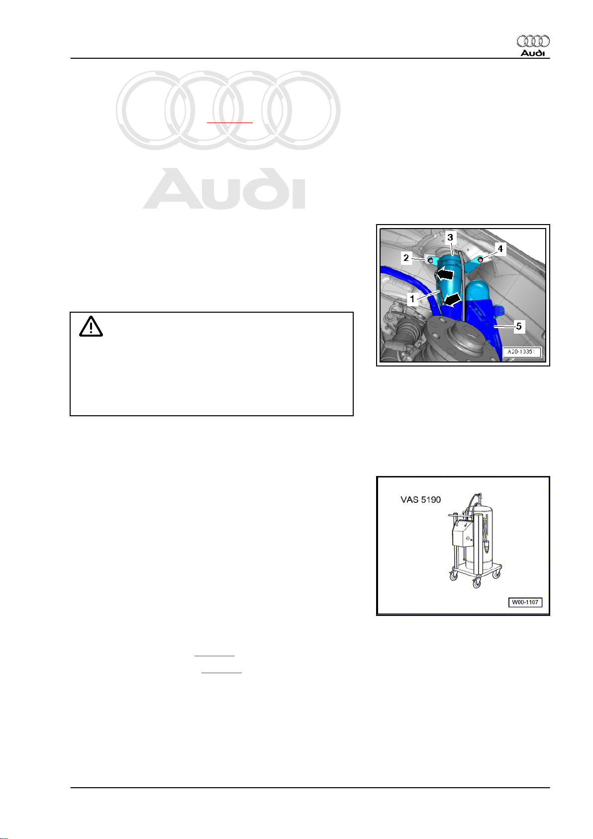
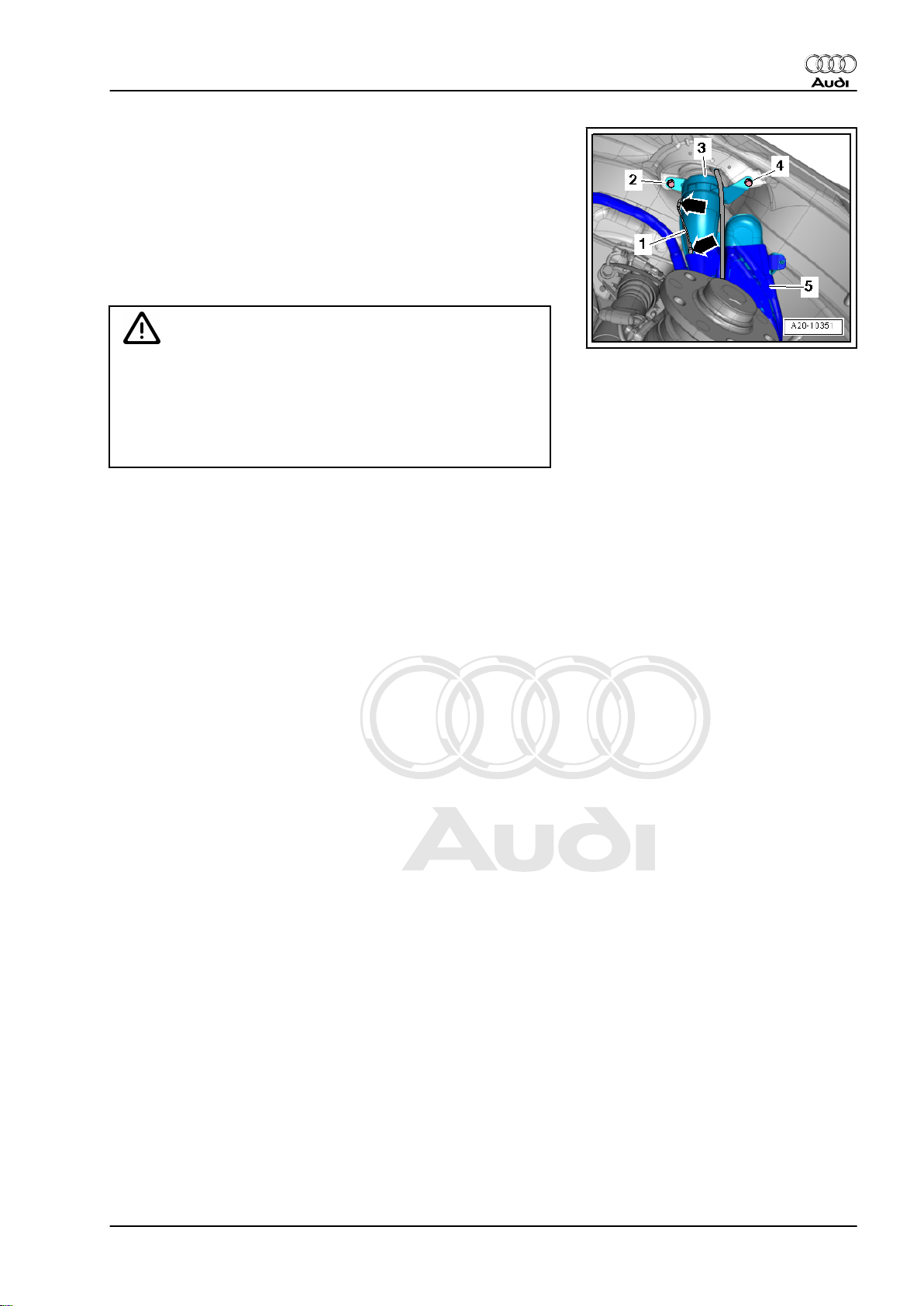
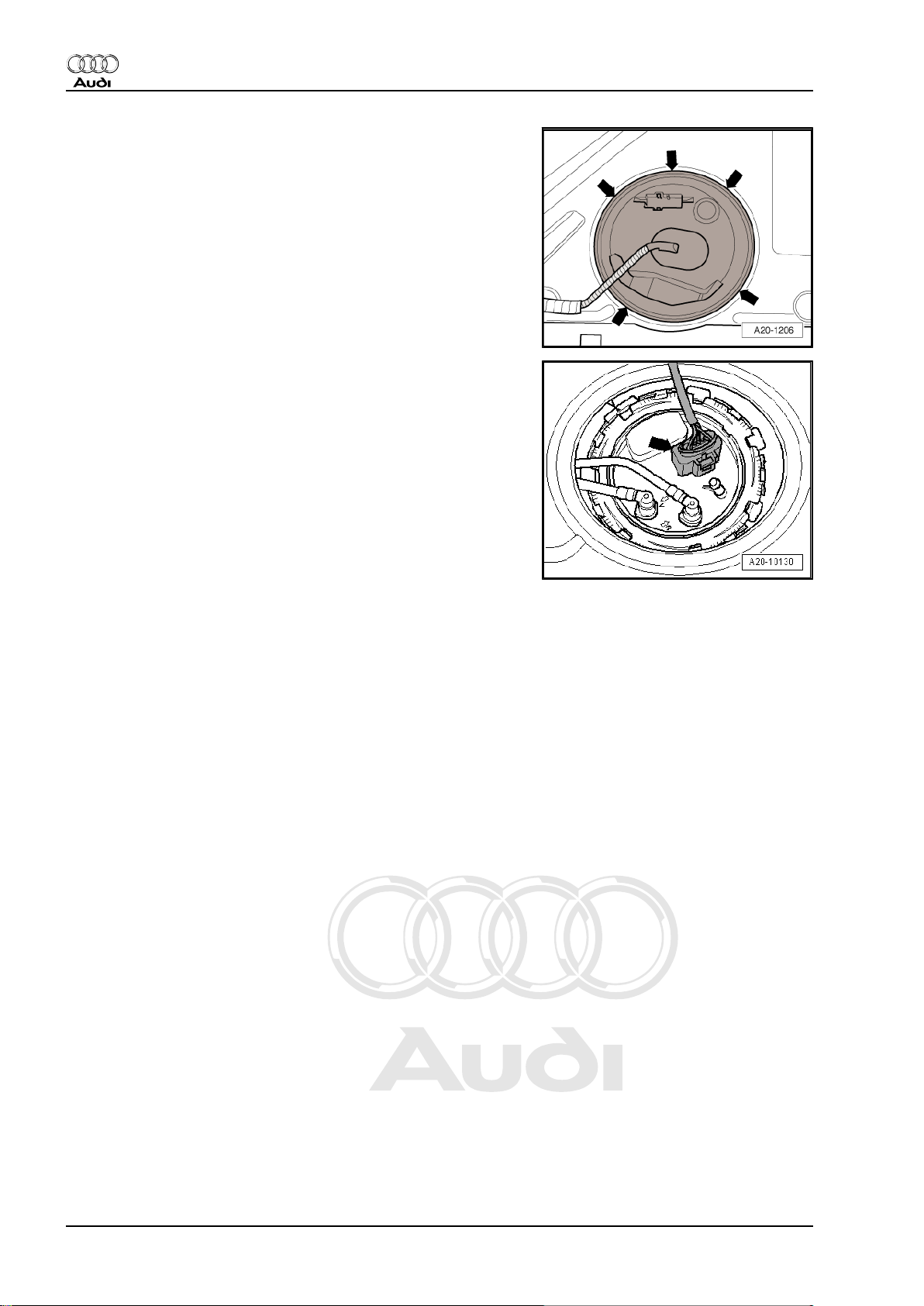
– Press flange down against spring pressure and move flange
into installation position.
• Lug -2- on flange must be between tabs -1- and -3- on fuel
tank.
Note
The -arrow- points in direction of travel.
– Tighten locking ring.
TT Coupé:
– Install rear seat bench ⇒ Rep. gr. 72 .
– Connect battery. Observe notes on procedures required after
connecting battery ⇒ Rep. gr. 27 .
TT Roadster:
– Install fuel tank: Rest-of-world vehicles with front-wheel drive
⇒ page 12 , USA vehicles with front-wheel drive ⇒ page 20 .
All vehicles (continued):
– Put at least 5 litres of fuel into tank after installing fuel delivery
unit.
– On vehicles with TFSI engine with toothed belt drive, the fuel
pump must be adapted after renewing the fuel delivery unit
⇒ page 33 .
Audi TT 2007 ➤
3.7 Adapting fuel pump after renewing fuel
delivery unit - vehicles with TFSI engine
with toothed belt drive
Note
♦
On vehicles with TFSI engine with toothed belt drive, the fuel
delivery unit must be adapted to the engine control unit after
renewing the fuel delivery unit.
♦
This operation is not required on vehicles with TFSI engine
with timing chain.
Special tools and workshop equipment required
3. Fuel delivery unit and fuel gauge sender - all vehicles with front-wheel drive 33
Page 38

Protected by copyright. Copying for private or commercial purposes, in part or in whole, is not
permitted unless authorised by AUDI AG. AUDI AG does not guarantee or accept any liability
with respect to the correctness of information in this document. Copyright by AUDI AG.
Audi TT 2007 ➤
Fuel supply system, petrol engines - Edition 11.2010
♦ Vehicle diagnostic, testing and information system -VAS
5051B-
Procedure
• No faults stored in event memory.
– Connect vehicle diagnostic, testing and information system -
VAS 5051B- to diagnostic connection -arrow- and start engine.
– Select following menu options:
♦ „Vehicle self-diagnosis“
♦ „01 - Engine electronics“
♦ „Basic setting, display group 103“
♦ „Activate“
– Check display in zone „4“.
Indicated on display: „ADP runs“. When the fuel pump has been
successfully adapted, the display will show „ADP OK“.
Note
If display shows „ADP n.OK“: interrogate event memory.
– End „vehicle self-diagnosis“.
– Switch off ignition and unplug diagnostic connector.
3.8 Checking fuel gauge sender -G-
Special tools and workshop equipment required
♦ Hand-held multimeter -V.A.G 1526D-
34 Rep. gr.20 - Fuel supply system
Page 39

Protected by copyright. Copying for private or commercial purposes, in part or in whole, is not
permitted unless authorised by AUDI AG. AUDI AG does not guarantee or accept any liability
with respect to the correctness of information in this document. Copyright by AUDI AG.
Fuel supply system, petrol engines - Edition 11.2010
♦ Auxiliary measuring set -V.A.G 1594C-
Procedure
TT Coupé:
– Remove rear seat bench ⇒ Rep. gr. 72 .
TT Roadster:
– Remove back panel side trim (right-side) ⇒ Rep. gr. 70 .
All vehicles (continued):
– Unclip retaining tabs -arrows- for flange cover.
Audi TT 2007 ➤
– Unplug electrical connector -arrow- at flange.
3. Fuel delivery unit and fuel gauge sender - all vehicles with front-wheel drive 35
Page 40

Protected by copyright. Copying for private or commercial purposes, in part or in whole, is not
permitted unless authorised by AUDI AG. AUDI AG does not guarantee or accept any liability
with respect to the correctness of information in this document. Copyright by AUDI AG.
Audi TT 2007 ➤
Fuel supply system, petrol engines - Edition 11.2010
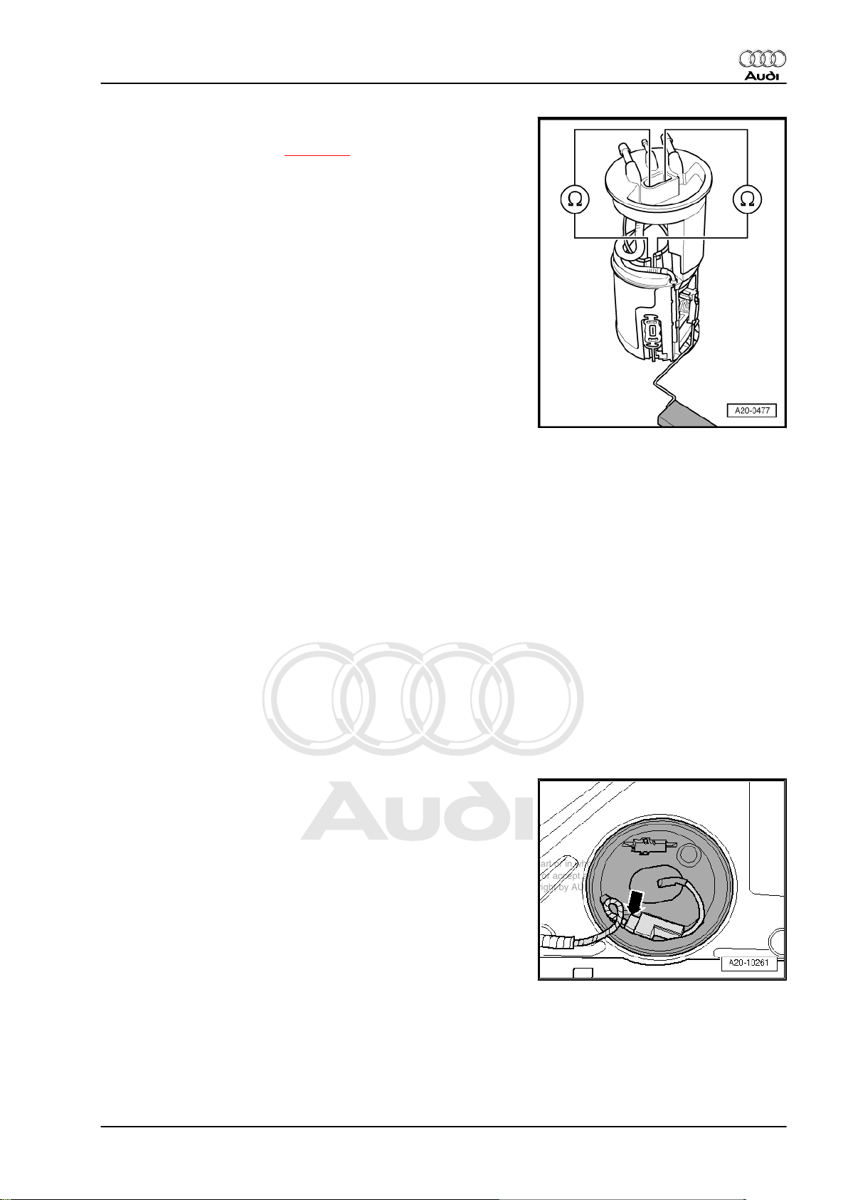
– Connect multimeter (resistance test) between contacts -2- and
-3-.
Fuel gauge sender -G- installed:
• Sender at lower stop: approx. 270 Ω.
• Sender at upper stop: approx. 70 Ω.
Note
♦
To test the maximum and minimum resistance values for „tank
full“ and „tank empty“, remove the fuel delivery unit
⇒ page 30 and move the sender float all the way to its top or
bottom position.
♦
If the resistance is 0 Ω, there is a short circuit. If the resistance
is ∞ Ω, there is an open circuit in the wiring.
♦
The following values are obtained with the fuel gauge sender
-G- removed, due to the greater travel of the float arm:
Fuel gauge sender -G- removed:
• Sender at lower stop: approx. 290 Ω.
• Sender at upper stop: approx. 50 Ω.
– Connect multimeter (resistance test) between contacts -3- and
-4-.
Fuel gauge sender -G- installed or removed:
• Sender in any position: approx. 340 Ω.
Installation is carried out in the reverse order; note the following:
TT Coupé:
– Install rear seat bench ⇒ Rep. gr. 72 .
TT Roadster:
– Install back panel side trim (right-side) ⇒ Rep. gr. 70 .
3.9 Removing and installing fuel gauge sender -G-
Removing
Observe safety precautions ⇒ page 4 .
Observe rules for cleanliness ⇒ page 4 .
TT Roadster:
Caution
• On the TT Roadster, the fuel tank must be removed before
removing the fuel gauge sender -G- .
– Remove fuel tank: Rest-of-world vehicles ⇒ page 8 , USA ve‐
hicles ⇒ page 16 .
All vehicles (continued):
– Remove fuel delivery unit ⇒ page 30 .
36 Rep. gr.20 - Fuel supply system
Page 41

Protected by copyright. Copying for private or commercial purposes, in part or in whole, is not
permitted unless authorised by AUDI AG. AUDI AG does not guarantee or accept any liability
with respect to the correctness of information in this document. Copyright by AUDI AG.
Fuel supply system, petrol engines - Edition 11.2010
Version 1:
Caution
Risk of damage.
♦ First release retainer tabs on connector contact before
detaching electrical connectors on fuel gauge sender -G- .
– Release and detach electrical connectors -1 … 3-.
– Lift retaining tabs -4- and -5- with a screwdriver and pull fuel
gauge sender -G- off downwards -arrow-.
Version 2:
– Use screwdriver to release retaining tabs -arrows- and lift out
fuel gauge sender -G- .
Audi TT 2007 ➤
Caution
Risk of damage.
♦ First release retainer tabs on connector contact before
detaching electrical connectors on fuel gauge sender -G- .
– Release and detach electrical connectors -1 … 3-.
Installing
Installation is carried out in the reverse order; note the following:
3. Fuel delivery unit and fuel gauge sender - all vehicles with front-wheel drive 37
Page 42

Protected by copyright. Copying for private or commercial purposes, in part or in whole, is not
permitted unless authorised by AUDI AG. AUDI AG does not guarantee or accept any liability
with respect to the correctness of information in this document. Copyright by AUDI AG.
Audi TT 2007 ➤
Fuel supply system, petrol engines - Edition 11.2010
Version 1:
– Insert fuel gauge sender -G- into guides on fuel delivery unit
and press upwards until it clicks into place.
– Plug in electrical connectors -1 ... 3- and check that they have
engaged properly.
Version 2:
– Plug in electrical connectors -1 ... 3- and check that they have
engaged properly.
– Insert fuel gauge sender -G- into guides on fuel delivery unit
and press upwards until it clicks into place.
All versions (continued):
– Install fuel delivery unit ⇒ page 32 ; observe instructions for
connecting battery.
38 Rep. gr.20 - Fuel supply system
Page 43

Protected by copyright. Copying for private or commercial purposes, in part or in whole, is not
permitted unless authorised by AUDI AG. AUDI AG does not guarantee or accept any liability
with respect to the correctness of information in this document. Copyright by AUDI AG.
Audi TT 2007 ➤
Fuel supply system, petrol engines - Edition 11.2010
4 Fuel tank with attached components
- rest-of-world vehicles with fourwheel drive
4.1 Fuel tank with attached components - exploded view
1 - Nut
❑ 23 Nm
2 - Heat shield for fuel tank
❑ With support bracket
3 - Fuel line
❑ To engine
❑ Press release tab on
pipe connector to dis‐
connect
4 - Breather line
❑ From gravity valve to ac‐
tivated charcoal filter
❑ Clip onto fuel tank
5 - Electrical connector
❑ For fuel system pressur‐
isation pump -G6- and
fuel gauge sender -G-
6 - Protective plate
❑ For fuel filler neck
7 - Filler cap
❑ Secured to tank flap unit
8 - Earth connection
❑ To eliminate electrostat‐
ic charge
❑ Installation position
⇒ page 40
❑ Make sure that connec‐
tor is securely fitted
❑ After installation, use an
ohmmeter to check the
electrical connection
between the protective plate -item 6- on the fuel filler neck and a bare metal part on the body. Specifi‐
cation: approx. 0 Ω
9 - Bolt
❑ 11 Nm
10 - Pop rivet
11 - Fuel tank
❑ Removing and installing ⇒ page 42
12 - Securing strap
❑ Installation position: Fixing point (hole) points in direction of travel
4. Fuel tank with attached components - rest-of-world vehicles with four-wheel drive 39
Page 44

Protected by copyright. Copying for private or commercial purposes, in part or in whole, is not
permitted unless authorised by AUDI AG. AUDI AG does not guarantee or accept any liability
with respect to the correctness of information in this document. Copyright by AUDI AG.
Audi TT 2007 ➤
Fuel supply system, petrol engines - Edition 11.2010
Earth connection for fuel filler neck and protective plate
– The connections -2- and -4- on filler neck must be free from
corrosion to ensure earth connection to body is not impaired.
– Position the earth connection as illustrated -1-.
– Ensure that connectors -arrows- for earth connection are prop‐
erly seated on protective plate -5- and on fuel filler neck -3-.
WARNING
Risk of explosion caused by electrostatic discharge.
♦ After installation, use an ohmmeter to check the electrical
connection between the metal ring on the fuel filler neck
and a bare metal part on the body:
• Specification: approx. 0 Ω.
4.2 Draining fuel tank
Special tools and workshop equipment required
♦ Wrench -T10202-
♦ Fuel extractor -VAS 5190-
Procedure
Observe safety precautions ⇒ page 4 .
Observe rules for cleanliness ⇒ page 4 .
– Release the tank flap.
40 Rep. gr.20 - Fuel supply system
Page 45

Protected by copyright. Copying for private or commercial purposes, in part or in whole, is not
permitted unless authorised by AUDI AG. AUDI AG does not guarantee or accept any liability
with respect to the correctness of information in this document. Copyright by AUDI AG.
Fuel supply system, petrol engines - Edition 11.2010
Caution
To prevent irreparable damage to the electronic components
when disconnecting the battery:
♦ Observe notes on procedure for disconnecting the battery.
– Disconnect battery ⇒ Rep. gr. 27 .
WARNING
Risk of explosion caused by electrostatic discharge.
♦ Secure earth wire of fuel extractor -VAS 5190- to a bare
metal part on the body.
– Detach tapered adapter -2- from shaft end -1- of fuel extractor
-VAS 5190- .
– Use insulating tape to mark the extraction hose -arrow- at a
distance of -a- = 1,370 mm from the end of the hose.
Audi TT 2007 ➤
– Remove filler cap from fuel filler neck.
– Screw shaft end of fuel extractor -VAS 5190- onto fuel filler
neck.
– Push extraction hose into fuel tank until marking on hose
-arrow- coincides with shaft end.
Note
♦
The procedure when using a fuel extractor without a shaft end
is fundamentally the same.
♦
In this case, make a mark -arrow- on the extraction hose at
distance -a- = 1,305 mm from the end of the hose using insu‐
lating tape. The extraction hose has been properly inserted
when the affixed mark is level with the edge of the filler neck.
♦
If hose is difficult to insert, apply a thin coat of engine oil. DO
NOT use silicone-based lubricant.
– Drain fuel tank as much as possible through fuel filler neck.
– Carefully remove extraction hose.
TT Coupé:
– Remove rear seat bench ⇒ Rep. gr. 72 .
TT Roadster:
– Remove back panel side trim (left-side) ⇒ Rep. gr. 70 .
4. Fuel tank with attached components - rest-of-world vehicles with four-wheel drive 41
Page 46

Protected by copyright. Copying for private or commercial purposes, in part or in whole, is not
permitted unless authorised by AUDI AG. AUDI AG does not guarantee or accept any liability
with respect to the correctness of information in this document. Copyright by AUDI AG.
Audi TT 2007 ➤
Fuel supply system, petrol engines - Edition 11.2010
All vehicles (continued):
– Unclip the retaining tabs -arrows- for the flange cover (left-
side).
– Unplug electrical connector -1- at flange.
– Disengage electrical connector -2- and move it clear to the
side.
– Unscrew locking ring using wrench -T10202- .
– Carefully pull fuel gauge sender 2 -G169- -item 1- with suction-
jet pump just slightly out of aperture in fuel tank.
Note
When removing, make sure you do not bend float arm of fuel
gauge sender 2 -G169- .
– Extract fuel from left fuel tank chamber through fuel tank open‐
ing using fuel extractor -VAS 5190- .
– Push hose into right-hand chamber of fuel tank and extract
remaining fuel.
– Re-install fuel gauge sender 2 -G169- ⇒ page 85 ; observe
notes on procedure for connecting battery.
4.3 Removing and installing fuel tank with attached components
Special tools and workshop equipment required
42 Rep. gr.20 - Fuel supply system
Page 47

Protected by copyright. Copying for private or commercial purposes, in part or in whole, is not
permitted unless authorised by AUDI AG. AUDI AG does not guarantee or accept any liability
with respect to the correctness of information in this document. Copyright by AUDI AG.
♦ Engine and gearbox jack -V.A.G 1383 A-
♦ Hook -3004-
Audi TT 2007 ➤
Fuel supply system, petrol engines - Edition 11.2010
Removing
Observe safety precautions ⇒ page 4 .
Observe rules for cleanliness ⇒ page 4 .
– Release the tank flap.
Caution
To prevent irreparable damage to the electronic components
when disconnecting the battery:
♦ Observe notes on procedure for disconnecting the battery.
– Disconnect battery ⇒ Rep. gr. 27 .
WARNING
Risk of accident caused by weight of fuel tank
♦ Fuel tank must be empty when it is removed.
– Drain fuel tank ⇒ page 40 .
4. Fuel tank with attached components - rest-of-world vehicles with four-wheel drive 43
Page 48

Protected by copyright. Copying for private or commercial purposes, in part or in whole, is not
permitted unless authorised by AUDI AG. AUDI AG does not guarantee or accept any liability
with respect to the correctness of information in this document. Copyright by AUDI AG.
Audi TT 2007 ➤
Fuel supply system, petrol engines - Edition 11.2010
– Clean area around fuel filler neck.
– Remove filler cap -arrow- from fuel filler neck.
– Seal opening of fuel filler neck with a piece of clean foam or
similar to prevent dirt from dropping into the tank.
– Remove rear right wheel housing liner ⇒ Rep. gr. 66 .
– Detach electrical wire -1- for ABS speed sensor from bracket
on fuel filler neck.
– Remove bolts -2- and -3- for fuel filler neck.
– Move overflow hose -4- on fuel filler neck clear.
– Remove diagonal struts ⇒ Rep. gr. 42 .
Caution
Risk of damage to flexible joints in front exhaust pipe
♦ The flexible joints in the front exhaust pipe must not be
bent more than 10°.
♦ Before slackening clamp on exhaust pipe, secure front
section of exhaust system to underbody of vehicle with a
chain.
– Disconnect exhaust system at clamp -1-.
– Secure front section of exhaust system with a chain. To do so,
engage hooks -3004- into openings on underside of vehicle
(remove plugs if fitted).
– Push the clamp back in order to separate the exhaust system.
Note
A second person will be required for detaching rear section of
exhaust system.
– Disengage rear silencer at the rubber mountings and remove
rear section of exhaust system.
– Remove propshaft ⇒ Rear final drive 02D/0AV/0BR/0BY;
Rep. gr. 39 .
44 Rep. gr.20 - Fuel supply system
Page 49

Protected by copyright. Copying for private or commercial purposes, in part or in whole, is not
permitted unless authorised by AUDI AG. AUDI AG does not guarantee or accept any liability
with respect to the correctness of information in this document. Copyright by AUDI AG.
Fuel supply system, petrol engines - Edition 11.2010
WARNING
Risk of injury - fuel system operates under high pressure.
♦ To reduce the pressure in the fuel system, wrap a clean
cloth around the connection and carefully loosen the con‐
nection.
– Disconnect fuel line -2- and breather line -1- from front right of
fuel tank by pressing release tab.
WARNING
Risk of accident caused by weight of fuel tank
♦ Fuel tank must be empty when it is removed.
Audi TT 2007 ➤
– First remove bolts -2, 5, 6-.
– Disengage wiring harness -arrows- and move clear.
– Position engine and gearbox jack -V.A.G 1383 A- below vehi‐
cle to support tank.
– Remove bolts -1, 3, 4, and 7-.
Caution
Risk of overstretching electrical wiring.
♦ Subsequently, when lowering fuel tank, make sure that
electrical wiring is not under tension.
– Lower fuel tank using engine and gearbox jack -V.A.G 1383
A- only until you can reach electrical connectors on flanges
with your hand.
Note
The following two illustrations show the electrical connectors on
the flanges in their installation position.
– Unplug electrical connector -1- on flange (left-side).
– Disengage electrical connector -2- for Haldex coupling.
4. Fuel tank with attached components - rest-of-world vehicles with four-wheel drive 45
Page 50

Protected by copyright. Copying for private or commercial purposes, in part or in whole, is not
permitted unless authorised by AUDI AG. AUDI AG does not guarantee or accept any liability
with respect to the correctness of information in this document. Copyright by AUDI AG.
Audi TT 2007 ➤
Fuel supply system, petrol engines - Edition 11.2010
– Unplug electrical connector -arrow- at flange (right-side).
– Then lower fuel tank using engine and gearbox jack -V.A.G
1383 A- , simultaneously guiding fuel tank down by hand.
– Remove fuel tank downwards (turning it sideways as re‐
quired).
– In addition, a 2nd mechanic will be required to guide the fuel
filler neck on trailing arm out by hand.
Installing
• Tightening torques ⇒ page 39
Installation is carried out in the reverse order; note the following:
– Position fuel tank with securing straps on underbody, using
engine and gearbox jack -V.A.G 1383 A- .
– Attach wiring harness at top of fuel tank.
– When installing fuel tank, make sure that the fuel filler neck is
correctly inserted into the opening on the body.
– Secure fuel tank by first tightening bolts at points -1, 3, 4, 7-,
then at points -2, 5, 6-.
46 Rep. gr.20 - Fuel supply system
Page 51

Protected by copyright. Copying for private or commercial purposes, in part or in whole, is not
permitted unless authorised by AUDI AG. AUDI AG does not guarantee or accept any liability
with respect to the correctness of information in this document. Copyright by AUDI AG.
Fuel supply system, petrol engines - Edition 11.2010
– The connections -2- and -4- on filler neck must be free from
corrosion to ensure earth connection to body is not impaired.
– Tighten bolts -2- and -4- for fuel filler neck.
– Check the earth wiring at both ends for traces of oxidation and
remove oxidation if necessary.
– Position the earth connection as illustrated -1-.
– Ensure that connectors -arrows- for earth connection are prop‐
erly seated on protective plate -5- and on fuel filler neck -3-.
WARNING
Risk of explosion caused by electrostatic discharge.
♦ After installation, use an ohmmeter to check the electrical
connection between the metal ring on the fuel filler neck
and a bare metal part on the body:
• Specification: approx. 0 Ω.
– Attach electrical wire for ABS speed sensor to bracket on fuel
filler neck.
– Install rear right wheel housing liner ⇒ Rep. gr. 66 .
– Install propshaft ⇒ Rear final drive 02D/0AV/0BR/0BY; Rep.
gr. 39 .
– Install rear section of exhaust system ⇒ Rep. gr. 26 .
TT Roadster:
– Install diagonal struts ⇒ Rep. gr. 42 .
All vehicles (continued):
– Connect battery. Observe notes on procedures required after
connecting battery ⇒ Rep. gr. 27 .
Audi TT 2007 ➤
4. Fuel tank with attached components - rest-of-world vehicles with four-wheel drive 47
Page 52

Protected by copyright. Copying for private or commercial purposes, in part or in whole, is not
permitted unless authorised by AUDI AG. AUDI AG does not guarantee or accept any liability
with respect to the correctness of information in this document. Copyright by AUDI AG.
Audi TT 2007 ➤
Fuel supply system, petrol engines - Edition 11.2010
5 Fuel tank with attached components
- USA vehicles with four-wheel drive
5.1 Fuel tank with attached components - exploded view
1 - Nut
❑ 23 Nm
2 - Heat shield for fuel tank
❑ With support bracket
3 - Nut
❑ 23 Nm
4 - Fuel line
❑ To engine
❑ Press release tab on
pipe connector to dis‐
connect
5 - Breather line
❑ From activated charcoal
filter to activated char‐
coal filter solenoid
valve 1 -N80-
❑ Clip onto fuel tank
6 - Electrical connector
❑ For fuel system pressur‐
isation pump -G6- and
fuel gauge sender -G-
7 - Protective plate
❑ For fuel filler neck
8 - Bolt
❑ 11 Nm
9 - Filler cap
❑ Secured to tank flap unit
10 - Earth connection
❑ To eliminate electrostat‐
ic charge
❑ Installation position ⇒ page 49
❑ Make sure that connector is securely fitted
❑ After installation, use an ohmmeter to check the electrical connection between the protective plate
-item 7- on the fuel filler neck and a bare metal part on the body. Specification: approx. 0 Ω
11 - Breather line
❑ From gravity valve to activated charcoal filter
❑ Clip onto bracket in wheel housing
❑ Press release tab on pipe connector to disconnect
12 - Pop rivet
13 - Fuel tank
❑ Removing and installing ⇒ page 51
48 Rep. gr.20 - Fuel supply system
Page 53

Protected by copyright. Copying for private or commercial purposes, in part or in whole, is not
permitted unless authorised by AUDI AG. AUDI AG does not guarantee or accept any liability
with respect to the correctness of information in this document. Copyright by AUDI AG.
Fuel supply system, petrol engines - Edition 11.2010
14 - Securing strap
❑ Installation position: Fixing point (hole) points in direction of travel
Earth connection for fuel filler neck and protective plate
– The connections -2- and -4- on filler neck must be free from
corrosion to ensure earth connection to body is not impaired.
– Position the earth connection as illustrated -1-.
– Ensure that connectors -arrows- for earth connection are prop‐
erly seated on protective plate -5- and on fuel filler neck -3-.
WARNING
Risk of explosion caused by electrostatic discharge.
♦ After installation, use an ohmmeter to check the electrical
connection between the metal ring on the fuel filler neck
and a bare metal part on the body:
• Specification: approx. 0 Ω.
Audi TT 2007 ➤
5.2 Draining fuel tank
Special tools and workshop equipment required
♦ Wrench -T10202-
♦ Fuel extractor -VAS 5190-
Procedure
Observe safety precautions ⇒ page 4 .
Observe rules for cleanliness ⇒ page 4 .
– Release the tank flap.
5. Fuel tank with attached components - USA vehicles with four-wheel drive 49
Page 54

Protected by copyright. Copying for private or commercial purposes, in part or in whole, is not
permitted unless authorised by AUDI AG. AUDI AG does not guarantee or accept any liability
with respect to the correctness of information in this document. Copyright by AUDI AG.
Audi TT 2007 ➤
Fuel supply system, petrol engines - Edition 11.2010
Caution
To prevent irreparable damage to the electronic components
when disconnecting the battery:
♦ Observe notes on procedure for disconnecting the battery.
– Disconnect battery ⇒ Rep. gr. 27 .
WARNING
Risk of explosion caused by electrostatic discharge.
♦ Secure earth wire of fuel extractor -VAS 5190- to a bare
metal part on the body.
– Detach tapered adapter -2- from shaft end -1- of fuel extractor
-VAS 5190- .
– Use insulating tape to mark the extraction hose -arrow- at a
distance of -a- = 1,370 mm from the end of the hose.
– Remove filler cap from fuel filler neck.
– Screw shaft end of fuel extractor -VAS 5190- onto fuel filler
neck.
– Push extraction hose into fuel tank until marking on hose
-arrow- coincides with shaft end.
Note
♦
The procedure when using a fuel extractor without a shaft end
is fundamentally the same.
♦
In this case, make a mark -arrow- on the extraction hose at
distance -a- = 1,305 mm from the end of the hose using insu‐
lating tape. The extraction hose has been properly inserted
when the affixed mark is level with the edge of the filler neck.
♦
If hose is difficult to insert, apply a thin coat of engine oil. DO
NOT use silicone-based lubricant.
– Drain fuel tank as much as possible through fuel filler neck.
– Carefully remove extraction hose.
TT Coupé:
– Remove rear seat bench ⇒ Rep. gr. 72 .
TT Roadster:
– Remove back panel side trim (left-side) ⇒ Rep. gr. 70 .
50 Rep. gr.20 - Fuel supply system
Page 55

Protected by copyright. Copying for private or commercial purposes, in part or in whole, is not
permitted unless authorised by AUDI AG. AUDI AG does not guarantee or accept any liability
with respect to the correctness of information in this document. Copyright by AUDI AG.
Fuel supply system, petrol engines - Edition 11.2010
All vehicles (continued):
– Unclip the retaining tabs -arrows- for the flange cover (left-
side).
– Unplug electrical connector -1- at flange.
– Disengage electrical connector -2- and move it clear to the
side.
Audi TT 2007 ➤
– Unscrew locking ring using wrench -T10202- .
– Carefully pull fuel gauge sender 2 -G169- -item 1- with suction-
jet pump just slightly out of aperture in fuel tank.
Note
When removing, make sure you do not bend float arm of fuel
gauge sender 2 -G169- .
– Extract fuel from left fuel tank chamber through fuel tank open‐
ing using fuel extractor -VAS 5190- .
– Push hose into right-hand chamber of fuel tank and extract
remaining fuel.
– Re-install fuel gauge sender 2 -G169- ⇒ page 85 ; observe
notes on procedure for connecting battery.
5.3 Removing and installing fuel tank with attached components
Special tools and workshop equipment required
5. Fuel tank with attached components - USA vehicles with four-wheel drive 51
Page 56

Protected by copyright. Copying for private or commercial purposes, in part or in whole, is not
permitted unless authorised by AUDI AG. AUDI AG does not guarantee or accept any liability
with respect to the correctness of information in this document. Copyright by AUDI AG.
Audi TT 2007 ➤
Fuel supply system, petrol engines - Edition 11.2010
♦ Engine and gearbox jack -V.A.G 1383 A-
♦ Hook -3004-
Removing
Observe safety precautions ⇒ page 4 .
Observe rules for cleanliness ⇒ page 4 .
– Release the tank flap.
Caution
To prevent irreparable damage to the electronic components
when disconnecting the battery:
♦ Observe notes on procedure for disconnecting the battery.
– Disconnect battery ⇒ Rep. gr. 27 .
WARNING
Risk of accident caused by weight of fuel tank
♦ Fuel tank must be empty when it is removed.
– Drain fuel tank ⇒ page 49 .
52 Rep. gr.20 - Fuel supply system
Page 57

Protected by copyright. Copying for private or commercial purposes, in part or in whole, is not
permitted unless authorised by AUDI AG. AUDI AG does not guarantee or accept any liability
with respect to the correctness of information in this document. Copyright by AUDI AG.
Fuel supply system, petrol engines - Edition 11.2010
– Clean area around fuel filler neck.
– Remove filler cap -arrow- from fuel filler neck.
– Seal opening of fuel filler neck with a piece of clean foam or
similar to prevent dirt from dropping into the tank.
– Remove rear right wheel housing liner ⇒ Rep. gr. 66 .
– Remove bolts -3- and -4- for fuel filler neck.
– Remove breather line -2- going to activated charcoal filter
(press release tab).
– Detach electrical wire -1- for ABS speed sensor from bracket
on fuel filler neck.
– Move overflow hose -5- on fuel filler neck clear.
Audi TT 2007 ➤
– Remove diagonal struts ⇒ Rep. gr. 42 .
– Press release tab and disconnect breather line -arrow- leading
to activated charcoal filter.
Caution
Risk of damage to flexible joints in front exhaust pipe
♦ The flexible joints in the front exhaust pipe must not be
bent more than 10°.
♦ Before slackening clamp on exhaust pipe, secure front
section of exhaust system to underbody of vehicle with a
chain.
– Disconnect exhaust system at clamp -1-.
5. Fuel tank with attached components - USA vehicles with four-wheel drive 53
Page 58

Protected by copyright. Copying for private or commercial purposes, in part or in whole, is not
permitted unless authorised by AUDI AG. AUDI AG does not guarantee or accept any liability
with respect to the correctness of information in this document. Copyright by AUDI AG.
Audi TT 2007 ➤
Fuel supply system, petrol engines - Edition 11.2010
– Secure front section of exhaust system with a chain. To do so,
engage hooks -3004- into openings on underside of vehicle
(remove plugs if fitted).
– Push the clamp back in order to separate the exhaust system.
Note
A second person will be required for detaching rear section of
exhaust system.
– Disengage rear silencer at the rubber mountings and remove
rear section of exhaust system.
– Remove propshaft ⇒ Rear final drive 02D/0AV/0BR/0BY;
Rep. gr. 39 .
– Press release tab and disconnect breather line -2- at front right
of fuel tank.
WARNING
Risk of injury - fuel system operates under high pressure.
♦ To reduce the pressure in the fuel system, wrap a clean
cloth around the connection and carefully loosen the con‐
nection.
– Press release tab and disconnect fuel line -1- at front right of
fuel tank.
WARNING
Risk of accident caused by weight of fuel tank
♦ Fuel tank must be empty when it is removed.
– First remove bolts -2, 5, 6-.
– Disengage wiring harness -arrows- and move clear.
– Position engine and gearbox jack -V.A.G 1383 A- below vehi‐
cle to support tank.
– Remove bolts -1, 3, 4, and 7-.
Caution
Risk of overstretching electrical wiring.
♦ Subsequently, when lowering fuel tank, make sure that
electrical wiring is not under tension.
– Lower fuel tank using engine and gearbox jack -V.A.G 1383
A- only until you can reach electrical connectors on flanges
with your hand.
54 Rep. gr.20 - Fuel supply system
Page 59

Protected by copyright. Copying for private or commercial purposes, in part or in whole, is not
permitted unless authorised by AUDI AG. AUDI AG does not guarantee or accept any liability
with respect to the correctness of information in this document. Copyright by AUDI AG.
Fuel supply system, petrol engines - Edition 11.2010
Note
The following two illustrations show the electrical connectors on
the flanges in their installation position.
– Unplug electrical connector -1- on flange (left-side).
– Disengage electrical connector -2- for Haldex coupling.
– Unplug electrical connector -arrow- at flange (right-side).
– Then lower fuel tank using engine and gearbox jack -V.A.G
1383 A- , simultaneously guiding fuel tank down by hand.
– Remove fuel tank downwards (turning it sideways as re‐
quired).
– In addition, a 2nd mechanic will be required to guide the fuel
filler neck on trailing arm out by hand.
Installing
• Tightening torques ⇒ page 48
Installation is carried out in the reverse order; note the following:
– Position fuel tank with securing straps on underbody, using
engine and gearbox jack -V.A.G 1383 A- .
– Attach wiring harness at top of fuel tank.
– When installing fuel tank, make sure that the fuel filler neck is
correctly inserted into the opening on the body.
Audi TT 2007 ➤
– Secure fuel tank by first tightening bolts at points -1, 3, 4, 7-,
then at points -2, 5, 6-.
5. Fuel tank with attached components - USA vehicles with four-wheel drive 55
Page 60

Protected by copyright. Copying for private or commercial purposes, in part or in whole, is not
permitted unless authorised by AUDI AG. AUDI AG does not guarantee or accept any liability
with respect to the correctness of information in this document. Copyright by AUDI AG.
Audi TT 2007 ➤
Fuel supply system, petrol engines - Edition 11.2010
– The connections -2- and -4- on filler neck must be free from
corrosion to ensure earth connection to body is not impaired.
– Tighten bolts -2- and -4- for fuel filler neck.
– Check the earth wiring at both ends for traces of oxidation and
remove oxidation if necessary.
– Position the earth connection as illustrated -1-.
– Ensure that connectors -arrows- for earth connection are prop‐
erly seated on protective plate -5- and on fuel filler neck -3-.
WARNING
Risk of explosion caused by electrostatic discharge.
♦ After installation, use an ohmmeter to check the electrical
connection between the metal ring on the fuel filler neck
and a bare metal part on the body:
• Specification: approx. 0 Ω.
– Attach electrical wire for ABS speed sensor to bracket on fuel
filler neck.
– Install breather line (leading to activated charcoal filter) at filler
neck.
– Install rear right wheel housing liner ⇒ Rep. gr. 66 .
– Install propshaft ⇒ Rear final drive 02D/0AV/0BR/0BY; Rep.
gr. 39 .
– Install rear section of exhaust system ⇒ Rep. gr. 26 .
TT Roadster:
– Install diagonal struts ⇒ Rep. gr. 42 .
All vehicles (continued):
– Connect battery. Observe notes on procedures required after
connecting battery ⇒ Rep. gr. 27 .
56 Rep. gr.20 - Fuel supply system
Page 61

Protected by copyright. Copying for private or commercial purposes, in part or in whole, is not
permitted unless authorised by AUDI AG. AUDI AG does not guarantee or accept any liability
with respect to the correctness of information in this document. Copyright by AUDI AG.
Audi TT 2007 ➤
Fuel supply system, petrol engines - Edition 11.2010
6 Fuel delivery unit and fuel gauge
senders - all vehicles with four-wheel
drive
6.1 Fuel delivery unit and fuel gauge senders - exploded view
1 - Fuel gauge sender -G-
❑ Checking resistance
values ⇒ page 78
❑ Removing and installing
⇒ page 80
2 - Fuel delivery unit with
flange
❑ Checking fuel pump
(electrical test)
⇒ page 58
❑ Checking residual pres‐
sure ⇒ Rep. gr. 24
❑ Removing and installing
⇒ page 73
❑ Put at least 5 litres of
fuel into tank after instal‐
ling
3 - Seal
❑ Renew
❑ Install dry
4 - Fuel supply line
❑ To fuel filter
❑ Do not kink
❑ Attached to connection
marked „V“ on flange
❑ To disconnect from
flange, press release
tab on connection
5 - Fuel return line
❑ From fuel filter
❑ Do not kink
❑ Attached to connection
marked „R“ on flange
❑ To disconnect from flange, press release tab on connection
6 - Electrical connector
❑ For fuel system pressurisation pump -G6- and fuel gauge sender -G-
7 - Locking ring
❑ Remove and install using wrench -T10202❑ 110 Nm
8 - Fuel supply pipe
❑ From suction-jet pump to fuel delivery unit
❑ Clipped onto fuel delivery unit
9 - Electrical connector
❑ For fuel gauge sender 2 -G169-
6. Fuel delivery unit and fuel gauge senders - all vehicles with four-wheel drive 57
Page 62

Protected by copyright. Copying for private or commercial purposes, in part or in whole, is not
permitted unless authorised by AUDI AG. AUDI AG does not guarantee or accept any liability
with respect to the correctness of information in this document. Copyright by AUDI AG.
Audi TT 2007 ➤
Fuel supply system, petrol engines - Edition 11.2010
10 - Locking ring
❑ Remove and install using wrench -T10202❑ 110 Nm
11 - Seal
❑ Renew
❑ Install dry
12 - Fuel gauge sender 2 -G169-
❑ Only available together with -item 13-.
❑ Installation position ⇒ page 86
❑ Checking resistance values ⇒ page 81
❑ Removing and installing ⇒ page 83
13 - Suction-jet pump
❑ With pipes
❑ Only available together with -item 12-.
❑ Removing and installing ⇒ page 87
14 - Supply pipe for suction-jet pump
❑ From fuel pump to suction-jet pump
❑ Press release tab on pipe connector to disconnect
6.2 Checking fuel pump (electrical test)
Special tools and workshop equipment required
♦ Remote control -V.A.G 1348/3A- for V.A.G 1348 with adapter
cable -V.A.G 1348/3-2-
♦ Hand-held multimeter -V.A.G 1526D-
58 Rep. gr.20 - Fuel supply system
Page 63

Protected by copyright. Copying for private or commercial purposes, in part or in whole, is not
permitted unless authorised by AUDI AG. AUDI AG does not guarantee or accept any liability
with respect to the correctness of information in this document. Copyright by AUDI AG.
Fuel supply system, petrol engines - Edition 11.2010
♦ Auxiliary measuring set -V.A.G 1594C-
Procedure
Observe test conditions ⇒ page 4 .
– Press the two clips in direction of the -arrows- and remove
cover from electronics box in engine compartment.
Audi TT 2007 ➤
– Detach fuse at position 1 -arrow- from „fuse holder
ST2“ (brown) -item 2-.
– Connect remote control -V.A.G 1348/3A- for V.A.G 1348 with
adapter cable -V.A.G 1348/3-2- to fuse contact for fuel pump
and to the positive „+“ battery terminal.
– Press remote control button -V.A.G 1348/3 A- .
• Pump should start running audibly.
Note
The fuel pump runs very quietly. Where possible, avoid noisy sur‐
roundings for this test.
If no noise can be heard from pump:
TT Coupé:
– Remove rear seat bench ⇒ Rep. gr. 72 .
TT Roadster:
– Remove back panel side trim (right-side) ⇒ Rep. gr. 70 .
6. Fuel delivery unit and fuel gauge senders - all vehicles with four-wheel drive 59
Page 64

Protected by copyright. Copying for private or commercial purposes, in part or in whole, is not
permitted unless authorised by AUDI AG. AUDI AG does not guarantee or accept any liability
with respect to the correctness of information in this document. Copyright by AUDI AG.
Audi TT 2007 ➤
Fuel supply system, petrol engines - Edition 11.2010
All vehicles (continued):
– Unclip the retaining tabs -arrows- for the flange cover (right-
side).
– Unplug electrical connector -arrow- at flange.
– Connect multimeter between contacts -1- and -5- of connector
to measure voltage.
– Press remote control button.
• Specification: approx. battery voltage
If specification is not obtained:
– Eliminate open circuit in wiring (refer to current flow diagram).
If reading matches specification although no noise can be heard
from pump:
– Remove fuel delivery unit ⇒ page 73 .
– Check that the electrical wires between flange and fuel pump
are connected and test for continuity.
If no faults are found in the wiring:
– Fuel pump is defective. Renew fuel delivery unit.
Installation is carried out in the reverse order; note the following:
– Install fuel delivery unit ⇒ page 76 .
60 Rep. gr.20 - Fuel supply system
Page 65

Protected by copyright. Copying for private or commercial purposes, in part or in whole, is not
permitted unless authorised by AUDI AG. AUDI AG does not guarantee or accept any liability
with respect to the correctness of information in this document. Copyright by AUDI AG.
Fuel supply system, petrol engines - Edition 11.2010
6.3 Checking fuel pump control unit -J538- vehicles with TFSI engine
♦ On vehicles with TFSI engine, voltage for the fuel pump is
supplied via fuel pump control unit -J538- .
♦ Check fuel pump control unit -J538- in „Guided Fault Finding“
⇒ Vehicle diagnostic, testing and information system
VAS 5051.
6.4 Removing and installing fuel pump con‐
trol unit -J538- - vehicles with 1.8 ltr./
2.0 ltr. TFSI engine
Removing
TT Coupé:
– Remove rear seat bench ⇒ Rep. gr. 72 .
TT Roadster:
– Remove back panel side trim (right-side) ⇒ Rep. gr. 70 .
All vehicles (continued):
– Remove fuel pump control unit -J538- from cover for flange
and unplug electrical connector -arrow-.
Audi TT 2007 ➤
– Unclip the retaining tabs -arrows- for the flange cover (right-
side).
– Unplug electrical connector -arrow- at flange.
Installing
Installation is carried out in the reverse order; note the following:
TT Coupé:
– Install rear seat bench ⇒ Rep. gr. 72 .
TT Roadster:
– Install back panel side trim (right-side) ⇒ Rep. gr. 70 .
6. Fuel delivery unit and fuel gauge senders - all vehicles with four-wheel drive 61
Page 66

Protected by copyright. Copying for private or commercial purposes, in part or in whole, is not
permitted unless authorised by AUDI AG. AUDI AG does not guarantee or accept any liability
with respect to the correctness of information in this document. Copyright by AUDI AG.
Audi TT 2007 ➤
Fuel supply system, petrol engines - Edition 11.2010
6.5 Removing and installing fuel pump con‐
trol unit -J538- - vehicles with 2.5 ltr.
TFSI engine
Removing
TT Coupé:
– Remove rear seat bench ⇒ Rep. gr. 72 .
TT Roadster:
– Remove back panel side trim (right-side) ⇒ Rep. gr. 70 .
All vehicles (continued):
– Take electrical connector -3- out of flange cover and unplug
(press release tab).
– Pull grommet -1- off flange cover -2-.
– Unclip retaining tabs -arrows- for flange cover.
– Detach flange cover.
– Unplug electrical connector -arrow- at flange.
62 Rep. gr.20 - Fuel supply system
Page 67

Protected by copyright. Copying for private or commercial purposes, in part or in whole, is not
permitted unless authorised by AUDI AG. AUDI AG does not guarantee or accept any liability
with respect to the correctness of information in this document. Copyright by AUDI AG.
Fuel supply system, petrol engines - Edition 11.2010
– Disengage handbrake cable -1- from bracket.
– Remove bolts -4-.
Caution
Risk of overstretching electrical wiring.
♦ Lower fuel tank using engine and gearbox jack -V.A.G
1383 A- by max. 20 mm so that fuel pump control unit can
be detached together with electrical wiring harness and
connector.
Audi TT 2007 ➤
– Remove bolts -3, 4, 5-.
– Lower fuel tank with engine and gearbox jack -V.A.G 1383 A-
by max. 20 mm.
– Detach bracket -3- with control unit -2-, and at the same time
guide out electrical connector and wiring harness for fuel pump
control unit.
Installing
Installation is carried out in the reverse order; note the following:
TT Coupé:
– Install rear seat bench ⇒ Rep. gr. 72 .
TT Roadster:
– Install back panel side trim (right-side) ⇒ Rep. gr. 70 .
6. Fuel delivery unit and fuel gauge senders - all vehicles with four-wheel drive 63
Page 68

Protected by copyright. Copying for private or commercial purposes, in part or in whole, is not
permitted unless authorised by AUDI AG. AUDI AG does not guarantee or accept any liability
with respect to the correctness of information in this document. Copyright by AUDI AG.
Audi TT 2007 ➤
Fuel supply system, petrol engines - Edition 11.2010
6.6 Checking fuel pump delivery rate - vehicles with 1.8 ltr./2.0 ltr. TFSI engine
Special tools and workshop
equipment required
♦ K-Jetronic pressure tester -
V.A.G 1318-
♦ Adapter -V.A.G 1318/11-
♦ Adapter -V.A.G
1318/17-1A-
♦ Connector -V.A.G 1318/23-
♦ Remote control -V.A.G
1348/3A- for V.A.G 1348
with adapter cable -V.A.G
1348/3-3-
♦ Auxiliary measuring set -
V.A.G 1594C-
♦ Fuel-resistant measuring
container
Procedure
Observe test conditions ⇒ page 4 .
TT Coupé:
– Remove rear seat bench ⇒ Rep. gr. 72 .
TT Roadster:
– Remove back panel side trim (right-side) ⇒ Rep. gr. 70 .
64 Rep. gr.20 - Fuel supply system
Page 69

Protected by copyright. Copying for private or commercial purposes, in part or in whole, is not
permitted unless authorised by AUDI AG. AUDI AG does not guarantee or accept any liability
with respect to the correctness of information in this document. Copyright by AUDI AG.
Fuel supply system, petrol engines - Edition 11.2010
All vehicles (continued):
– Unclip retaining tabs -arrows- for flange cover.
– Unplug electrical connector -arrow- at flange.
Audi TT 2007 ➤
– Connect remote control -V.A.G 1348/3A- for V.A.G 1348 to
contact -1- using adapter cable -V.A.G 1348/3-3- and test lead
from auxiliary measuring set -V.A.G 1594C- .
– Tape off 2nd connector contact of adapter cable -V.A.G
1348/3-3- with insulating tape -arrow- to prevent short circuits.
– Connect contact -5- to the body (earth) using a test lead from
auxiliary measuring set -V.A.G 1594C- .
– Connect crocodile clip to battery „+“ (positive terminal in en‐
gine compartment).
– Remove filler cap from fuel filler neck.
Rest-of-world vehicles with toothed belt drive:
– Detach fuel line from retainer and remove heat insulation
sleeve at fuel line connection.
WARNING
Risk of injury - fuel system operates under high pressure.
♦ To reduce the pressure in the fuel system, wrap a clean
cloth around the connection and carefully loosen the con‐
nection.
– Pull release ring and disconnect fuel line -arrow-.
6. Fuel delivery unit and fuel gauge senders - all vehicles with four-wheel drive 65
Page 70

Protected by copyright. Copying for private or commercial purposes, in part or in whole, is not
permitted unless authorised by AUDI AG. AUDI AG does not guarantee or accept any liability
with respect to the correctness of information in this document. Copyright by AUDI AG.
Audi TT 2007 ➤
Fuel supply system, petrol engines - Edition 11.2010
USA vehicles with toothed belt drive:
– Detach fuel line from retainer and remove heat insulation
sleeve -1- at fuel line connection.
WARNING
Risk of injury - fuel system operates under high pressure.
♦ To reduce the pressure in the fuel system, wrap a clean
cloth around the connection and carefully loosen the con‐
nection.
– Pull release ring and disconnect fuel line -arrow-.
Vehicles with timing chain:
– Push down protective sleeve -1- and disconnect fuel line.
– First press hose connector -2- downwards -arrow A-, then
press release tabs -arrow B-.
– Pull off hose connector, keeping release tabs depressed.
All vehicles (continued):
– Screw connector -V.A.G 1318/23- and adapter -V.A.G
1318/17-1A- onto K-Jetronic pressure tester -V.A.G 1318- .
– Fit adapter -V.A.G 1318/17-1A- onto disconnected fuel line.
– Screw adapter -V.A.G 1318/11- onto K-Jetronic pressure test‐
er -V.A.G 1318- .
– Attach test hose -arrow- and hold end of hose in measuring
container.
– Open cut-off valve on pressure tester.
• Lever must point in direction of flow.
– Build up pressure in fuel system by pressing the remote control
and slowly closing the cut-off valve on the pressure tester.
• Specification: 4 bar
– From this point on do not move position of cut-off valve.
– Empty the measuring container.
– Press remote control button for 15 seconds.
66 Rep. gr.20 - Fuel supply system
Page 71

Protected by copyright. Copying for private or commercial purposes, in part or in whole, is not
permitted unless authorised by AUDI AG. AUDI AG does not guarantee or accept any liability
with respect to the correctness of information in this document. Copyright by AUDI AG.
Fuel supply system, petrol engines - Edition 11.2010
– Compare amount of fuel delivered with minimum delivery
shown in diagram (cm3/15 sec.).
Note
Voltage at fuel pump with engine stationary and pump running is
approx. 2 volts less than battery voltage.
If minimum delivery rate is not reached, check for the following
causes:
♦ Fuel lines have been crushed.
♦ Fuel filter is blocked.
♦ Fuel pump is defective.
Installation is carried out in the reverse order; note the following:
TT Roadster:
– Install back panel side trim (right-side) ⇒ Rep. gr. 70 .
TT Coupé:
– Install rear seat bench ⇒ Rep. gr. 72 .
Audi TT 2007 ➤
6. Fuel delivery unit and fuel gauge senders - all vehicles with four-wheel drive 67
Page 72

Protected by copyright. Copying for private or commercial purposes, in part or in whole, is not
permitted unless authorised by AUDI AG. AUDI AG does not guarantee or accept any liability
with respect to the correctness of information in this document. Copyright by AUDI AG.
Audi TT 2007 ➤
Fuel supply system, petrol engines - Edition 11.2010
6.7 Checking fuel pump delivery rate - vehicles with 2.5 ltr. TFSI engine
Special tools and workshop
equipment required
♦ K-Jetronic pressure tester -
V.A.G 1318-
♦ Adapter -V.A.G 1318/11-
♦ Adapter -V.A.G
1318/17-1A-
♦ Connector -V.A.G 1318/23-
♦ Remote control -V.A.G
1348/3A- for V.A.G 1348
with adapter cable -V.A.G
1348/3-3-
♦ Auxiliary measuring set -
V.A.G 1594C-
♦ Fuel-resistant measuring
container
Procedure
Observe test conditions ⇒ page 4 .
TT Coupé:
– Remove rear seat bench ⇒ Rep. gr. 72 .
TT Roadster:
– Remove back panel side trim (right-side) ⇒ Rep. gr. 70 .
68 Rep. gr.20 - Fuel supply system
Page 73

Protected by copyright. Copying for private or commercial purposes, in part or in whole, is not
permitted unless authorised by AUDI AG. AUDI AG does not guarantee or accept any liability
with respect to the correctness of information in this document. Copyright by AUDI AG.
Fuel supply system, petrol engines - Edition 11.2010
All vehicles (continued):
– Unclip retaining tabs -arrows- for flange cover.
– Unplug electrical connector -arrow- at flange.
Audi TT 2007 ➤
– Connect remote control -V.A.G 1348/3A- for V.A.G 1348 to
contact -1- using adapter cable -V.A.G 1348/3-3- and test lead
from auxiliary measuring set -V.A.G 1594C- .
– Tape off 2nd connector contact of adapter cable -V.A.G
1348/3-3- with insulating tape -arrow- to prevent short circuits.
– Connect contact -5- to the body (earth) using a test lead from
auxiliary measuring set -V.A.G 1594C- .
– Connect crocodile clip to battery „+“ (positive terminal in en‐
gine compartment).
– Remove filler cap from fuel filler neck.
– Detach fuel line from retainer and remove heat insulation
sleeve -1- at fuel line connection.
WARNING
Risk of injury - fuel system operates under high pressure.
♦ To reduce the pressure in the fuel system, wrap a clean
cloth around the connection and carefully loosen the con‐
nection.
– Disconnect fuel line -3- by pulling release ring -2-.
6. Fuel delivery unit and fuel gauge senders - all vehicles with four-wheel drive 69
Page 74

Protected by copyright. Copying for private or commercial purposes, in part or in whole, is not
permitted unless authorised by AUDI AG. AUDI AG does not guarantee or accept any liability
with respect to the correctness of information in this document. Copyright by AUDI AG.
Audi TT 2007 ➤
Fuel supply system, petrol engines - Edition 11.2010
– Screw connector -V.A.G 1318/23- and adapter -V.A.G
1318/17-1A- onto K-Jetronic pressure tester -V.A.G 1318- .
– Fit adapter -V.A.G 1318/17-1A- onto disconnected fuel line.
– Screw adapter -V.A.G 1318/11- onto K-Jetronic pressure test‐
er -V.A.G 1318- .
– Attach test hose -arrow- and hold end of hose in measuring
container.
– Open cut-off valve on pressure tester.
• Lever must point in direction of flow.
– Build up pressure in fuel system by pressing the remote control
and slowly closing the cut-off valve on the pressure tester.
• Specification: 4 bar
– From this point on do not move position of cut-off valve.
– Empty the measuring container.
– Press remote control button for 15 seconds.
– Compare amount of fuel delivered with minimum delivery
shown in diagram (cm3/15 sec.).
Note
Voltage at fuel pump with engine stationary and pump running is
approx. 2 volts less than battery voltage.
If minimum delivery rate is not reached, check for the following
causes:
♦ Fuel lines have been crushed.
♦ Fuel filter is blocked.
♦ Fuel pump is defective.
Installation is carried out in the reverse order; note the following:
TT Roadster:
– Install back panel side trim (right-side) ⇒ Rep. gr. 70 .
TT Coupé:
– Install rear seat bench ⇒ Rep. gr. 72 .
6.8 Checking fuel pump delivery rate - vehi‐
cles with 3.2 ltr. MPI engine
Special tools and workshop equipment required
70 Rep. gr.20 - Fuel supply system
Page 75

Protected by copyright. Copying for private or commercial purposes, in part or in whole, is not
permitted unless authorised by AUDI AG. AUDI AG does not guarantee or accept any liability
with respect to the correctness of information in this document. Copyright by AUDI AG.
Fuel supply system, petrol engines - Edition 11.2010
♦ Adapter -V.A.G 1318/17-1- from adapter set -V.A.G 1318/17-
♦ Remote control -V.A.G 1348/3A- for V.A.G 1348 with adapter
cable -V.A.G 1348/3-3-
Audi TT 2007 ➤
♦ Fuel-resistant measuring container
Procedure
Observe test conditions ⇒ page 4 .
– Remove filler cap from fuel filler neck.
TT Coupé:
– Remove rear seat bench ⇒ Rep. gr. 72 .
TT Roadster:
– Remove back panel side trim (right-side) ⇒ Rep. gr. 70 .
All vehicles (continued):
– Unclip the retaining tabs -arrows- for the flange cover (right-
side).
6. Fuel delivery unit and fuel gauge senders - all vehicles with four-wheel drive 71
Page 76

Protected by copyright. Copying for private or commercial purposes, in part or in whole, is not
permitted unless authorised by AUDI AG. AUDI AG does not guarantee or accept any liability
with respect to the correctness of information in this document. Copyright by AUDI AG.
Audi TT 2007 ➤
Fuel supply system, petrol engines - Edition 11.2010
– Unplug electrical connector -arrow- at flange.
– Connect remote control -V.A.G 1348/3A- for V.A.G 1348 to
contact -1- using adapter cable -V.A.G 1348/3-3- and test lead
from auxiliary measuring set -V.A.G 1594C- .
– Tape off 2nd connector contact of adapter cable -V.A.G
1348/3-3- with insulating tape -arrow- to prevent short circuits.
– Connect contact -5- to the body (earth) using a test lead from
auxiliary measuring set -V.A.G 1594C- .
– Connect crocodile clip to battery „+“.
Risk of injury - fuel system operates under high pressure.
WARNING
♦ To reduce the pressure in the fuel system, wrap a clean
cloth around the connection and carefully loosen the con‐
nection.
– Press release tab and disconnect fuel return line -arrow-.
– Fit adapter -V.A.G 1318/17-1- onto disconnected fuel return
line and hold adapter hose in measuring container.
– Press remote control button for 15 seconds.
72 Rep. gr.20 - Fuel supply system
Page 77

Protected by copyright. Copying for private or commercial purposes, in part or in whole, is not
permitted unless authorised by AUDI AG. AUDI AG does not guarantee or accept any liability
with respect to the correctness of information in this document. Copyright by AUDI AG.
Fuel supply system, petrol engines - Edition 11.2010
– Compare amount of fuel delivered with minimum delivery
shown in diagram (cm3/15 sec.).
Note
Voltage at fuel pump with engine stationary and pump running is
approx. 2 volts less than battery voltage.
If minimum delivery rate is not reached, check for the following
causes:
♦ Fuel lines have been crushed.
♦ Fuel filter is blocked.
♦ Fuel pump is defective.
Installation is carried out in the reverse order; note the following:
TT Coupé:
– Install rear seat bench ⇒ Rep. gr. 72 .
TT Roadster:
– Install back panel side trim (right-side) ⇒ Rep. gr. 70 .
Audi TT 2007 ➤
6.9 Removing and installing fuel delivery unit
Special tools and workshop equipment required
♦ Wrench -T10202-
Removing
Observe safety precautions ⇒ page 4 .
Observe rules for cleanliness ⇒ page 4 .
Caution
To prevent irreparable damage to the electronic components
when disconnecting the battery:
♦ Observe notes on procedure for disconnecting the battery.
– Disconnect battery ⇒ Rep. gr. 27 .
6. Fuel delivery unit and fuel gauge senders - all vehicles with four-wheel drive 73
Page 78

Protected by copyright. Copying for private or commercial purposes, in part or in whole, is not
permitted unless authorised by AUDI AG. AUDI AG does not guarantee or accept any liability
with respect to the correctness of information in this document. Copyright by AUDI AG.
Audi TT 2007 ➤
Fuel supply system, petrol engines - Edition 11.2010
TT Roadster:
Caution
• On the TT Roadster, the fuel tank must first be removed
before removing the fuel delivery unit.
– Remove fuel tank: Rest-of-world vehicles ⇒ page 42 , USA
vehicles ⇒ page 51 .
TT Coupé:
WARNING
Large amounts of fuel can escape.
♦
The fuel tank must not be more than 1/3 full when remov‐
ing the fuel delivery unit, otherwise a large amount of fuel
will escape.
– Drain fuel tank if necessary: Rest-of-world vehicles
⇒ page 40 , USA vehicles ⇒ page 49 .
– Remove rear seat bench ⇒ Rep. gr. 72 .
– Unclip the retaining tabs -arrows- for the flange cover (right-
side).
– Unplug electrical connector -arrow- at flange.
74 Rep. gr.20 - Fuel supply system
Page 79

Protected by copyright. Copying for private or commercial purposes, in part or in whole, is not
permitted unless authorised by AUDI AG. AUDI AG does not guarantee or accept any liability
with respect to the correctness of information in this document. Copyright by AUDI AG.
Fuel supply system, petrol engines - Edition 11.2010
– Mark fuel supply line -1- and fuel return line -2-.
WARNING
Risk of injury - fuel system operates under high pressure.
♦ To reduce the pressure in the fuel system, wrap a clean
cloth around the connection and carefully loosen the con‐
nection.
– Detach both pipes from flange (press release tabs).
TT Roadster:
– With fuel tank removed, mark fuel supply line -1- and fuel re‐
turn line -2-.
– Detach both pipes from flange (press release tabs).
TT Coupé:
WARNING
Audi TT 2007 ➤
Large amounts of fuel can escape.
♦
The fuel tank must not be more than 1/3 full when remov‐
ing the fuel delivery unit, otherwise a large amount of fuel
will escape.
All vehicles (continued):
– Unscrew locking ring using wrench -T10202- .
– Take flange (right-side) and seal of fuel delivery unit out of
opening in fuel tank and move clear, leaving pipes connected.
6. Fuel delivery unit and fuel gauge senders - all vehicles with four-wheel drive 75
Page 80

Protected by copyright. Copying for private or commercial purposes, in part or in whole, is not
permitted unless authorised by AUDI AG. AUDI AG does not guarantee or accept any liability
with respect to the correctness of information in this document. Copyright by AUDI AG.
Audi TT 2007 ➤
Fuel supply system, petrol engines - Edition 11.2010
– In opening in fuel tank, press release tab to disconnect supply
pipe -2- to suction-jet pump.
– Disconnect fuel supply pipe -1- (press release catch -arrow-).
– Remove fuel delivery unit.
Note
♦
When removing fuel delivery unit, make sure you do not bend
float arm of fuel gauge sender -G- .
♦
Keep in mind that the fuel delivery unit still contains fuel.
Installing
• Tightening torque ⇒ page 57
Installation is carried out in the reverse order; note the following:
Note
♦
Renew seal.
♦
Take care not to bend the fuel gauge sender -G- when fitting
the fuel delivery unit.
♦
Ensure that fuel hoses are securely seated.
– Insert fuel delivery unit into fuel tank, with flange set aside.
– Fit fuel supply pipe -1-, so that it engages (you should hear it
click into place).
– Fit supply pipe -2- leading to suction-jet pump so that it en‐
gages audibly.
76 Rep. gr.20 - Fuel supply system
Page 81

Protected by copyright. Copying for private or commercial purposes, in part or in whole, is not
permitted unless authorised by AUDI AG. AUDI AG does not guarantee or accept any liability
with respect to the correctness of information in this document. Copyright by AUDI AG.
Fuel supply system, petrol engines - Edition 11.2010
– Install new seal for flange (seal must be installed dry).
– Slot guide sleeve on flange into guide sleeve on fuel delivery
unit; make sure spring is not damaged.
Caution
Leakage risk
♦ The seal must not be pinched or damaged when installing
the flange.
– Press flange down against spring pressure and move flange
into installation position.
• Lug -2- on flange points towards arrow marking, and must be
between tabs -1- and -3- on fuel tank.
Note
The -arrow- points in direction of travel.
Audi TT 2007 ➤
– Tighten locking ring.
TT Coupé:
– Install rear seat bench ⇒ Rep. gr. 72 .
– Connect battery. Observe notes on procedures required after
connecting battery ⇒ Rep. gr. 27 .
TT Roadster:
– Install fuel tank: Rest-of-world vehicles with four-wheel drive
⇒ page 46 , USA vehicles with four-wheel drive ⇒ page 55 .
All vehicles (continued):
– Put at least 5 litres of fuel into tank after installing fuel delivery
unit.
– On vehicles with TFSI engine with toothed belt drive, the fuel
pump must be adapted after renewing the fuel delivery unit
⇒ page 77 .
6.10 Adapting fuel pump after renewing fuel
delivery unit - vehicles with TFSI engine
with toothed belt drive
Note
♦
On vehicles with TFSI engine with toothed belt drive, the fuel
delivery unit must be adapted to the engine control unit after
renewing the fuel delivery unit.
♦
This operation is not required on vehicles with TFSI engine
with timing chain.
Special tools and workshop equipment required
6. Fuel delivery unit and fuel gauge senders - all vehicles with four-wheel drive 77
Page 82

Protected by copyright. Copying for private or commercial purposes, in part or in whole, is not
permitted unless authorised by AUDI AG. AUDI AG does not guarantee or accept any liability
with respect to the correctness of information in this document. Copyright by AUDI AG.
Audi TT 2007 ➤
Fuel supply system, petrol engines - Edition 11.2010
♦ Vehicle diagnostic, testing and information system -VAS
5051B-
Procedure
• No faults stored in event memory.
– Connect vehicle diagnostic, testing and information system -
VAS 5051B- to diagnostic connection -arrow- and start engine.
– Select following menu options:
♦ „Vehicle self-diagnosis“
♦ „01 - Engine electronics“
♦ „Basic setting, display group 103“
♦ „Activate“
– Check display in zone „4“.
Indicated on display: „ADP runs“. When the fuel pump has been
successfully adapted, the display will show „ADP OK“.
Note
If display shows „ADP n.OK“: interrogate event memory.
– End „vehicle self-diagnosis“.
– Switch off ignition and unplug diagnostic connector.
6.11 Checking fuel gauge sender -G-
Special tools and workshop equipment required
♦ Hand-held multimeter -V.A.G 1526D-
78 Rep. gr.20 - Fuel supply system
Page 83

Protected by copyright. Copying for private or commercial purposes, in part or in whole, is not
permitted unless authorised by AUDI AG. AUDI AG does not guarantee or accept any liability
with respect to the correctness of information in this document. Copyright by AUDI AG.
Fuel supply system, petrol engines - Edition 11.2010
♦ Auxiliary measuring set -V.A.G 1594C-
Procedure
TT Coupé:
– Remove rear seat bench ⇒ Rep. gr. 72 .
TT Roadster:
– Remove back panel side trim (right-side) ⇒ Rep. gr. 70 .
All vehicles (continued):
– Unclip the retaining tabs -arrows- for the flange cover (right-
side).
Audi TT 2007 ➤
– Unplug electrical connector -arrow- at flange.
6. Fuel delivery unit and fuel gauge senders - all vehicles with four-wheel drive 79
Page 84

Protected by copyright. Copying for private or commercial purposes, in part or in whole, is not
permitted unless authorised by AUDI AG. AUDI AG does not guarantee or accept any liability
with respect to the correctness of information in this document. Copyright by AUDI AG.
Audi TT 2007 ➤
Fuel supply system, petrol engines - Edition 11.2010
– Connect multimeter (resistance test) between contacts -2- and
-3-.
Fuel gauge sender -G- installed:
• Sender at lower stop: approx. 270 Ω.
• Sender at upper stop: approx. 70 Ω.
Note
♦
To test the maximum and minimum resistance values for „tank
full“ and „tank empty“, remove the fuel delivery unit
⇒ page 73 and move the sender float all the way to its top or
bottom position.
♦
If the resistance is 0 Ω, there is a short circuit. If the resistance
is ∞ Ω, there is an open circuit in the wiring.
♦
The following values are obtained with the fuel gauge sender
-G- removed, due to the greater travel of the float arm:
Fuel gauge sender -G- removed:
• Sender at lower stop: approx. 290 Ω.
• Sender at upper stop: approx. 60 Ω.
– Connect multimeter (resistance test) between contacts -3- and
-4-.
Fuel gauge sender -G- installed or removed:
• Sender in any position: approx. 340 Ω.
Installation is carried out in the reverse order; note the following:
TT Coupé:
– Install rear seat bench ⇒ Rep. gr. 72 .
TT Roadster:
– Install back panel side trim (right-side) ⇒ Rep. gr. 70 .
6.12 Removing and installing fuel gauge sender -G-
Removing
Observe safety precautions ⇒ page 4 .
Observe rules for cleanliness ⇒ page 4 .
TT Roadster:
Caution
• On the TT Roadster, the fuel tank must first be removed
before removing the fuel delivery unit.
– Remove fuel tank: Rest-of-world vehicles ⇒ page 42 , USA
vehicles ⇒ page 51 .
80 Rep. gr.20 - Fuel supply system
Page 85

Protected by copyright. Copying for private or commercial purposes, in part or in whole, is not
permitted unless authorised by AUDI AG. AUDI AG does not guarantee or accept any liability
with respect to the correctness of information in this document. Copyright by AUDI AG.
Fuel supply system, petrol engines - Edition 11.2010
All vehicles (continued):
– Remove fuel delivery unit ⇒ page 73 .
Caution
Risk of damage.
♦ First release retainer tabs on connector contact before
detaching electrical connectors on fuel gauge sender -G- .
– Release and detach electrical connectors -1 … 3-.
– Lift retaining tabs -4- and -5- with a screwdriver and pull fuel
gauge sender -G- off downwards -arrow-.
Installing
Installation is carried out in the reverse order; note the following:
– Insert fuel gauge sender -G- into guides on fuel delivery unit
and press upwards until it clicks into place.
– Plug in electrical connectors and check that they have engag‐
ed properly.
– Install fuel delivery unit ⇒ page 76 ; observe instructions for
connecting battery.
Audi TT 2007 ➤
6.13 Checking fuel gauge sender 2 -G169-
Special tools and workshop equipment required
♦ Hand-held multimeter -V.A.G 1526D-
♦ Auxiliary measuring set -V.A.G 1594C-
6. Fuel delivery unit and fuel gauge senders - all vehicles with four-wheel drive 81
Page 86

Protected by copyright. Copying for private or commercial purposes, in part or in whole, is not
permitted unless authorised by AUDI AG. AUDI AG does not guarantee or accept any liability
with respect to the correctness of information in this document. Copyright by AUDI AG.
Audi TT 2007 ➤
Fuel supply system, petrol engines - Edition 11.2010
Procedure
TT Coupé:
– Remove rear seat bench ⇒ Rep. gr. 72 .
TT Roadster:
– Remove back panel side trim (left-side) ⇒ Rep. gr. 70 .
All vehicles (continued):
– Unclip the retaining tabs -arrows- for the flange cover (left-
side).
– Unplug electrical connector -1- at flange.
Note
Disregard -item 2-.
82 Rep. gr.20 - Fuel supply system
Page 87

Protected by copyright. Copying for private or commercial purposes, in part or in whole, is not
permitted unless authorised by AUDI AG. AUDI AG does not guarantee or accept any liability
with respect to the correctness of information in this document. Copyright by AUDI AG.
Fuel supply system, petrol engines - Edition 11.2010
– Connect multimeter (resistance test) between contacts -1- and
-2-.
With fuel gauge sender 2 -G169- installed:
• Sender at lower stop: approx. 270 Ω.
• Sender at upper stop: approx. 70 Ω.
Note
♦
In order to test the maximum and minimum values for „tank
full“ and „tank empty“, remove the fuel gauge sender 2 -G169-
⇒ page 83 and move the float all the way to its top or bottom
position.
♦
If the resistance is 0 Ω, there is a short circuit. If the resistance
is ∞ Ω, there is an open circuit in the wiring.
♦
The following values are obtained with the fuel gauge sender 2
-G169- removed, due to the greater travel of the float arm:
With fuel gauge sender 2 -G169- removed:
• Sender at lower stop: approx. 286 Ω.
• Sender at upper stop: approx. 50 Ω.
– Connect multimeter (resistance test) between contacts -2- and
-3-.
With fuel gauge sender 2 -G169- installed or removed:
• Sender in any position: approx. 340 Ω.
Installation is carried out in the reverse order; note the following:
TT Coupé:
– Install rear seat bench ⇒ Rep. gr. 72 .
TT Roadster:
– Install back panel side trim (left-side) ⇒ Rep. gr. 70 .
Audi TT 2007 ➤
6.14 Removing and installing fuel gauge sender 2 -G169-
Special tools and workshop equipment required
♦ Wrench -T10202-
Removing
Observe safety precautions ⇒ page 4 .
Observe rules for cleanliness ⇒ page 4 .
6. Fuel delivery unit and fuel gauge senders - all vehicles with four-wheel drive 83
Page 88

Protected by copyright. Copying for private or commercial purposes, in part or in whole, is not
permitted unless authorised by AUDI AG. AUDI AG does not guarantee or accept any liability
with respect to the correctness of information in this document. Copyright by AUDI AG.
Audi TT 2007 ➤
Fuel supply system, petrol engines - Edition 11.2010
Caution
To prevent irreparable damage to the electronic components
when disconnecting the battery:
♦ Observe notes on procedure for disconnecting the battery.
– Disconnect battery ⇒ Rep. gr. 27 .
TT Roadster:
Caution
• On the TT Roadster, the fuel tank must first be removed
before removing the fuel gauge sender 2 -G169- .
– Remove fuel tank: Rest-of-world vehicles ⇒ page 42 , USA
vehicles ⇒ page 51 .
TT Coupé:
WARNING
Large amounts of fuel can escape.
♦
The fuel tank must not be more than 1/3 full when remov‐
ing the fuel gauge sender 2 -G169- ; otherwise a large
amount of fuel will escape.
– Drain fuel tank if necessary: Rest-of-world vehicles
⇒ page 40 , USA vehicles ⇒ page 49 .
– Briefly open filler cap for fuel tank and close again.
– Remove rear seat bench ⇒ Rep. gr. 72 .
– Unclip the retaining tabs -arrows- for the flange cover (left-
side).
– Unplug electrical connector -1- at flange.
– Disengage electrical connector -2- and move it clear to the
side.
84 Rep. gr.20 - Fuel supply system
Page 89

Protected by copyright. Copying for private or commercial purposes, in part or in whole, is not
permitted unless authorised by AUDI AG. AUDI AG does not guarantee or accept any liability
with respect to the correctness of information in this document. Copyright by AUDI AG.
Fuel supply system, petrol engines - Edition 11.2010
WARNING
Large amounts of fuel can escape.
♦
The fuel tank must not be more than 1/3 full when remov‐
ing the fuel gauge sender 2 -G169- ; otherwise a large
amount of fuel will escape.
All vehicles (continued):
– Unscrew locking ring using wrench -T10202- .
– Carefully pull fuel gauge sender 2 -G169- -item 2- together
with suction-jet pump -1- just slightly out of opening in fuel
tank.
– Detach seal.
– Unclip suction-jet pump from flange -arrows-.
Note
Audi TT 2007 ➤
When removing, make sure you do not bend float arm of fuel
gauge sender 2 -G169- .
Installing
• Tightening torque ⇒ page 57
Installation is carried out in the reverse order; note the following:
Note
♦
Renew seal.
♦
When installing, make sure you do not bend float arm of fuel
gauge sender 2 -G169- .
– Carefully insert fuel gauge sender 2 -G169- into opening in fuel
tank.
– Clip suction-jet pump -1- onto flange, so that you hear it click
into place.
6. Fuel delivery unit and fuel gauge senders - all vehicles with four-wheel drive 85
Page 90

Protected by copyright. Copying for private or commercial purposes, in part or in whole, is not
permitted unless authorised by AUDI AG. AUDI AG does not guarantee or accept any liability
with respect to the correctness of information in this document. Copyright by AUDI AG.
Audi TT 2007 ➤
Fuel supply system, petrol engines - Edition 11.2010
– Install new seal for flange (seal must be installed dry).
Caution
Leakage risk
♦ The seal must not be pinched or damaged when installing
the flange.
– Press flange down against spring pressure and move flange
into installation position.
• Lug -2- on flange points towards arrow marking, and must be
between tabs -1- and -3- on fuel tank.
Note
The -arrow- points in direction of travel.
– Tighten locking ring.
TT Coupé:
– Install rear seat bench ⇒ Rep. gr. 72 .
– Observe notes on procedures required after connecting bat‐
tery ⇒ Rep. gr. 27 .
TT Roadster:
– Install fuel tank: Rest-of-world vehicles with four-wheel drive
⇒ page 46 , USA vehicles with four-wheel drive ⇒ page 55 .
86 Rep. gr.20 - Fuel supply system
Page 91

Protected by copyright. Copying for private or commercial purposes, in part or in whole, is not
permitted unless authorised by AUDI AG. AUDI AG does not guarantee or accept any liability
with respect to the correctness of information in this document. Copyright by AUDI AG.
Fuel supply system, petrol engines - Edition 11.2010
6.15 Suction-jet pump
On vehicles with four-wheel drive the fuel tank is divided into a
left and a right chamber. A so-called suction-jet pump -1- is used
for delivering the fuel from the left fuel tank chamber -3- to the
baffle housing of the fuel delivery unit -2- on the right.
Suction-jet pump: operation
The suction-jet pump operates according to the principle of fluid
entrainment: the stream of fuel from the electric fuel pump is
passed through a nozzle in the suction-jet pump, and is thus ac‐
celerated. The accelerated stream of fuel draws off the surround‐
ing fuel and delivers it to the baffle housing of the fuel delivery
unit.
Faults caused by defective suction-jet pump
Caution
The engine can stop due to fuel starvation if the suction-jet
pump is defective.
♦ If the suction-jet pump is defective, the engine can stop
due to fuel starvation when the tank is still 1/4 full.
Audi TT 2007 ➤
If the suction-jet pump is not working, up to 15 litres of fuel (up to
about 1/4 of tank capacity) may remain in the left chamber of the
tank, where it cannot be drawn into the fuel delivery unit.
If the engine stops due to fuel starvation with the tank up to about
1
/4 full, proceed as follows:
– Check fuel pump ⇒ page 58 .
If fuel pump is OK, but no fuel is delivered:
– Put another 5 litres (approx.) of fuel into tank.
– Start engine.
If engine now starts:
– Renew suction-jet pump ⇒ page 87 .
6.16 Removing and installing suction-jet pump
Special tools and workshop equipment required
♦ Wrench -T10202-
Removing
Observe safety precautions ⇒ page 4 .
6. Fuel delivery unit and fuel gauge senders - all vehicles with four-wheel drive 87
Page 92

Protected by copyright. Copying for private or commercial purposes, in part or in whole, is not
permitted unless authorised by AUDI AG. AUDI AG does not guarantee or accept any liability
with respect to the correctness of information in this document. Copyright by AUDI AG.
Audi TT 2007 ➤
Fuel supply system, petrol engines - Edition 11.2010
Observe rules for cleanliness ⇒ page 4 .
Caution
To prevent irreparable damage to the electronic components
when disconnecting the battery:
♦ Observe notes on procedure for disconnecting the battery.
– Disconnect battery ⇒ Rep. gr. 27 .
TT Roadster:
Caution
• On the TT Roadster, the fuel tank must first be removed
before removing the suction-jet pump.
– Remove fuel tank: Rest-of-world vehicles ⇒ page 42 , USA
vehicles ⇒ page 51 .
TT Coupé:
WARNING
Large amounts of fuel can escape.
♦
The fuel tank must not be more than 1/3 full when remov‐
ing the suction-jet pump, otherwise a large amount of fuel
will escape.
– Drain fuel tank if necessary: Rest-of-world vehicles
⇒ page 40 , USA vehicles ⇒ page 49 .
– Remove rear seat bench ⇒ Rep. gr. 72 .
– Unclip the retaining tabs -arrows- for the flange cover (right-
side).
– Unplug electrical connector -arrow- at flange.
88 Rep. gr.20 - Fuel supply system
Page 93

Protected by copyright. Copying for private or commercial purposes, in part or in whole, is not
permitted unless authorised by AUDI AG. AUDI AG does not guarantee or accept any liability
with respect to the correctness of information in this document. Copyright by AUDI AG.
Fuel supply system, petrol engines - Edition 11.2010
– Mark fuel supply line -1- and fuel return line -2-.
WARNING
Risk of injury - fuel system operates under high pressure.
♦ To reduce the pressure in the fuel system, wrap a clean
cloth around the connection and carefully loosen the con‐
nection.
– Detach both pipes from flange (press release tabs).
– Unclip the retaining tabs -arrows- for the flange cover (left-
side).
Audi TT 2007 ➤
– Unplug electrical connector -1- at flange.
– Disengage electrical connector -2- and move it clear to the
side.
TT Roadster:
– With fuel tank removed, mark fuel supply line and fuel return
line on flange (right-side).
– Detach both pipes from flange (press release tabs).
TT Coupé:
WARNING
Large amounts of fuel can escape.
♦
The fuel tank must not be more than 1/3 full when remov‐
ing the suction-jet pump, otherwise a large amount of fuel
will escape.
All vehicles (continued):
– Unscrew locking ring (right-side) using wrench -T10202- .
6. Fuel delivery unit and fuel gauge senders - all vehicles with four-wheel drive 89
Page 94

Protected by copyright. Copying for private or commercial purposes, in part or in whole, is not
permitted unless authorised by AUDI AG. AUDI AG does not guarantee or accept any liability
with respect to the correctness of information in this document. Copyright by AUDI AG.
Audi TT 2007 ➤
Fuel supply system, petrol engines - Edition 11.2010
– Take flange and seal of fuel delivery unit out of opening in fuel
tank and move clear, leaving pipes connected.
– In opening in fuel tank, press release tab to disconnect supply
pipe -2- to suction-jet pump.
– Disconnect fuel supply pipe -1- (press release catch -arrow-).
– Unscrew locking ring (left-side) using wrench -T10202- .
– Carefully pull fuel gauge sender 2 -G169- -item 2- together
with suction-jet pump -1- just slightly out of opening in fuel
tank.
– Detach seal.
– Unclip suction-jet pump from flange -arrows-.
Note
When removing, make sure you do not bend float arm of fuel
gauge sender 2 -G169- .
– Reach into fuel tank opening on left side of vehicle and pull out
suction-jet pump, with pipes pointing towards the left.
Installing
• Tightening torque ⇒ page 57
Installation is carried out in the reverse order; note the following:
Note
♦
Renew seals.
♦
When installing, make sure you do not bend float arm of fuel
gauge sender 2 -G169- .
– Push suction-jet pump (with pipes attached) into fuel tank
opening on left side of vehicle.
90 Rep. gr.20 - Fuel supply system
Page 95

Protected by copyright. Copying for private or commercial purposes, in part or in whole, is not
permitted unless authorised by AUDI AG. AUDI AG does not guarantee or accept any liability
with respect to the correctness of information in this document. Copyright by AUDI AG.
Fuel supply system, petrol engines - Edition 11.2010
– Reach into fuel tank opening on right side of vehicle and pull
suction-jet pump with pipes into the installation position.
– Fit supply pipe -1-, so that it engages (you should hear it click
into place).
– Fit supply pipe -2- leading to suction-jet pump so that it en‐
gages audibly.
– Install new seal for flange (seal must be installed dry).
– Slot guide sleeve on flange into guide sleeve on fuel delivery
unit; make sure spring is not damaged.
Caution
Leakage risk
Audi TT 2007 ➤
♦ The seal must not be pinched or damaged when installing
the flange.
– Press flange down against spring pressure and move flange
into installation position.
• Lug -2- on flange points towards arrow marking, and must be
between tabs -1- and -3- on fuel tank.
Note
The -arrow- points in direction of travel.
– Tighten locking ring.
6. Fuel delivery unit and fuel gauge senders - all vehicles with four-wheel drive 91
Page 96

Protected by copyright. Copying for private or commercial purposes, in part or in whole, is not
permitted unless authorised by AUDI AG. AUDI AG does not guarantee or accept any liability
with respect to the correctness of information in this document. Copyright by AUDI AG.
Audi TT 2007 ➤
Fuel supply system, petrol engines - Edition 11.2010
– Carefully insert fuel gauge sender 2 -G169- into opening in fuel
tank.
– Clip suction-jet pump -1- onto flange -2-, so that you hear it
click into place.
– Install new seal for flange (seal must be installed dry).
Caution
Leakage risk
♦ The seal must not be pinched or damaged when installing
the flange.
– Press flange down against spring pressure and move flange
into installation position.
• Lug -2- on flange points towards arrow marking, and must be
between tabs -1- and -3- on fuel tank.
Note
The -arrow- points in direction of travel.
– Tighten locking ring.
TT Coupé:
– Install rear seat bench ⇒ Rep. gr. 72 .
– Observe notes on procedures required after connecting bat‐
tery ⇒ Rep. gr. 27 .
TT Roadster:
– Install fuel tank: Rest-of-world vehicles with four-wheel drive
⇒ page 46 , USA vehicles with four-wheel drive ⇒ page 55 .
All vehicles (continued):
– Put at least 5 litres of fuel into tank after installing suction-jet
pump
92 Rep. gr.20 - Fuel supply system
Page 97

Protected by copyright. Copying for private or commercial purposes, in part or in whole, is not
permitted unless authorised by AUDI AG. AUDI AG does not guarantee or accept any liability
with respect to the correctness of information in this document. Copyright by AUDI AG.
Fuel supply system, petrol engines - Edition 11.2010
7 Fuel filter - all vehicles
In the fuel system of the Audi TT, which has no direct fuel return
line, the fuel pressure regulator is located in the fuel filter. In this
system, only the supply pipe is routed to the front, to the engine
compartment. The fuel pressure regulator opens when the pres‐
sure in the fuel supply pipe rises above a specified value. Excess
fuel flows from the filter directly back to the tank via a return line.
7.1 Fuel filter - exploded view
1 - Fuel filter with fuel pressure
regulator
❑ For TFSI engine with
fuel pressure regulator:
6.4 bar
❑ For MPI engine with fuel
pressure regulator: 4
bar
❑ Flow direction is marked
by arrows
❑ Do not interchange con‐
nections
❑ Installation position: Pin
on filter housing must
engage in opening on fil‐
ter bracket guide
⇒ page 95
❑ Removing and installing
2 - Fuel supply line
❑ From fuel tank
❑ Press release tab on
3 - Fuel return line
❑ To fuel tank
❑ Press release tab on
4 - Fuel line
❑ To engine
❑ Press release tab on
5 - Bolt
❑ 1.5 Nm
6 - Bracket for fuel filter
❑ Attached to fuel tank
⇒ page 93
pipe connector to dis‐
connect
pipe connector to dis‐
connect
pipe connector to dis‐
connect
Audi TT 2007 ➤
7.2 Removing and installing fuel filter
Special tools and workshop equipment required
♦ Drip tray
7. Fuel filter - all vehicles 93
Page 98

Protected by copyright. Copying for private or commercial purposes, in part or in whole, is not
permitted unless authorised by AUDI AG. AUDI AG does not guarantee or accept any liability
with respect to the correctness of information in this document. Copyright by AUDI AG.
Audi TT 2007 ➤
Fuel supply system, petrol engines - Edition 11.2010
Removing
Observe safety precautions ⇒ page 4 .
Observe rules for cleanliness ⇒ page 4 .
TT Coupé:
– Remove rear seat bench ⇒ Rep. gr. 72 .
TT Roadster:
– Remove back panel side trim (right-side) ⇒ Rep. gr. 70 .
Vehicles with 1.8 ltr./2.0 ltr. TFSI engine:
WARNING
Fuel can escape.
♦ Fuel pump control unit -J538- must be disconnected from
the power supply to prevent the fuel pump from starting
up when the driver's door is opened.
– Remove fuel pump control unit -J538- from cover for flange
and unplug electrical connector -arrow-.
Vehicles with MPI engine:
WARNING
Fuel can escape.
♦ The fuel pump must be disconnected from the power sup‐
ply to prevent it from starting up when the driver's door is
opened.
– Unclip the retaining tabs -arrows- for the flange cover (right-
side).
– Unplug electrical connector -arrow- at flange.
Note
Unplugging the connector for the fuel pump will prevent the fuel
pump from being activated when the driver's door is opened.
94 Rep. gr.20 - Fuel supply system
Page 99

Protected by copyright. Copying for private or commercial purposes, in part or in whole, is not
permitted unless authorised by AUDI AG. AUDI AG does not guarantee or accept any liability
with respect to the correctness of information in this document. Copyright by AUDI AG.
Fuel supply system, petrol engines - Edition 11.2010
All vehicles (continued):
– Place drip tray below fuel filter.
WARNING
Risk of injury - fuel system operates under high pressure.
♦ To reduce the pressure in the fuel system, wrap a clean
cloth around the connection and carefully loosen the con‐
nection.
– Disconnect fuel lines -1, 2, 3- by pressing the release tab.
– Remove bolt -4-.
– Remove fuel filter.
Installing
• Tightening torque ⇒ page 93
Installation is carried out in the reverse order; note the following:
Installation position:
• Flow direction is marked with arrows on filter housing.
• Pin -2- on filter housing must engage in opening on filter brack‐
et guide -1-.
Audi TT 2007 ➤
7. Fuel filter - all vehicles 95
Page 100

Protected by copyright. Copying for private or commercial purposes, in part or in whole, is not
permitted unless authorised by AUDI AG. AUDI AG does not guarantee or accept any liability
with respect to the correctness of information in this document. Copyright by AUDI AG.
Audi TT 2007 ➤
Fuel supply system, petrol engines - Edition 11.2010
8 Activated charcoal filter system - rest-
of-world vehicles
8.1 Activated charcoal filter system - exploded view
Note
Illustration shows version for vehicles with 3.2 ltr. MPI engine as an example.
1 - Activated charcoal filter
❑ Removing and installing
⇒ page 96
2 - Spring-type clip
3 - Breather line
❑ To activated charcoal fil‐
ter solenoid valve 1 N80-
4 - Breather line
❑ To fuel tank
5 - Bolt
❑ 8 Nm
6 - Nut
❑ 8 Nm
7 - Bracket for activated char‐
coal filter
8 - Bolt
❑ 8 Nm
8.2 Removing and installing activated char‐
coal filter
Special tools and workshop equipment required
96 Rep. gr.20 - Fuel supply system
 Loading...