

Page 1
220
Service.
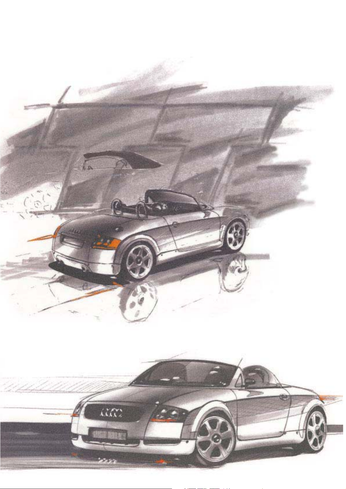
Audi TT Roadster
Design and Function
For internal use only
Self-Study Programme 220
Page 2
2
Page 3

Page
Body
Body Overview ....................................................................... 4
Roll bar ................................................................................... 6
Occupant protection ............................................................ 7
Gantry gauge ......................................................................... 8
Soft top control
Semiautomatic soft top ...................................................... 10
Soft top design .................................................................... 12
Hydraulic diagram ............................................................... 14
Fitting locations
Manual soft top ..................................................... 18
Semiautomatic soft top ........................................ 19
System overview .................................................................. 20
Function diagram ................................................................ 25
Contents
Bulkhead . . . . . . . . . . . . . . . . . . . . . . . . . . . . 26
Central locking . . . . . . . . . . . . . . . . . . . . . . . 28
Interior monitor . . . . . . . . . . . . . . . . . . . . . . 29
The Self-Study Programme provides you with information regarding designs and functions.
The Self-Study Programme is not a Workshop Manual!
For maintenance and repair work, always refer to the current
Technical Literature.
New! Important!
Note!
3
Page 4
Body
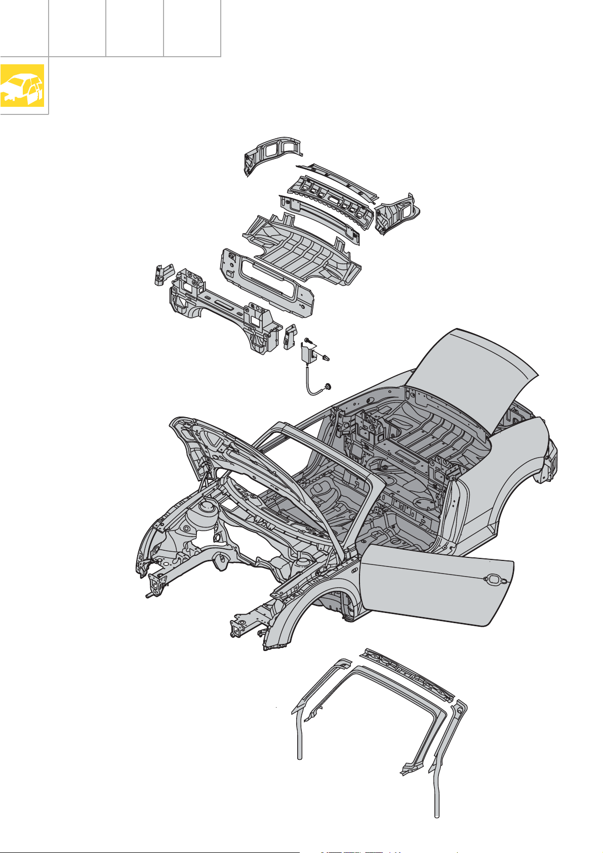
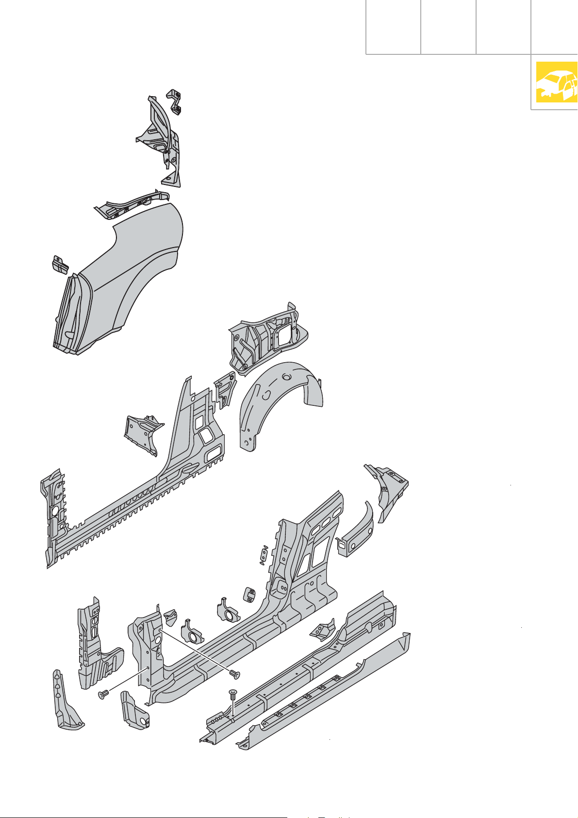
Body Overview
4
Page 5
SSP220_001
5
Page 6
Body
Roll bar
SSP220_002
6
Page 7
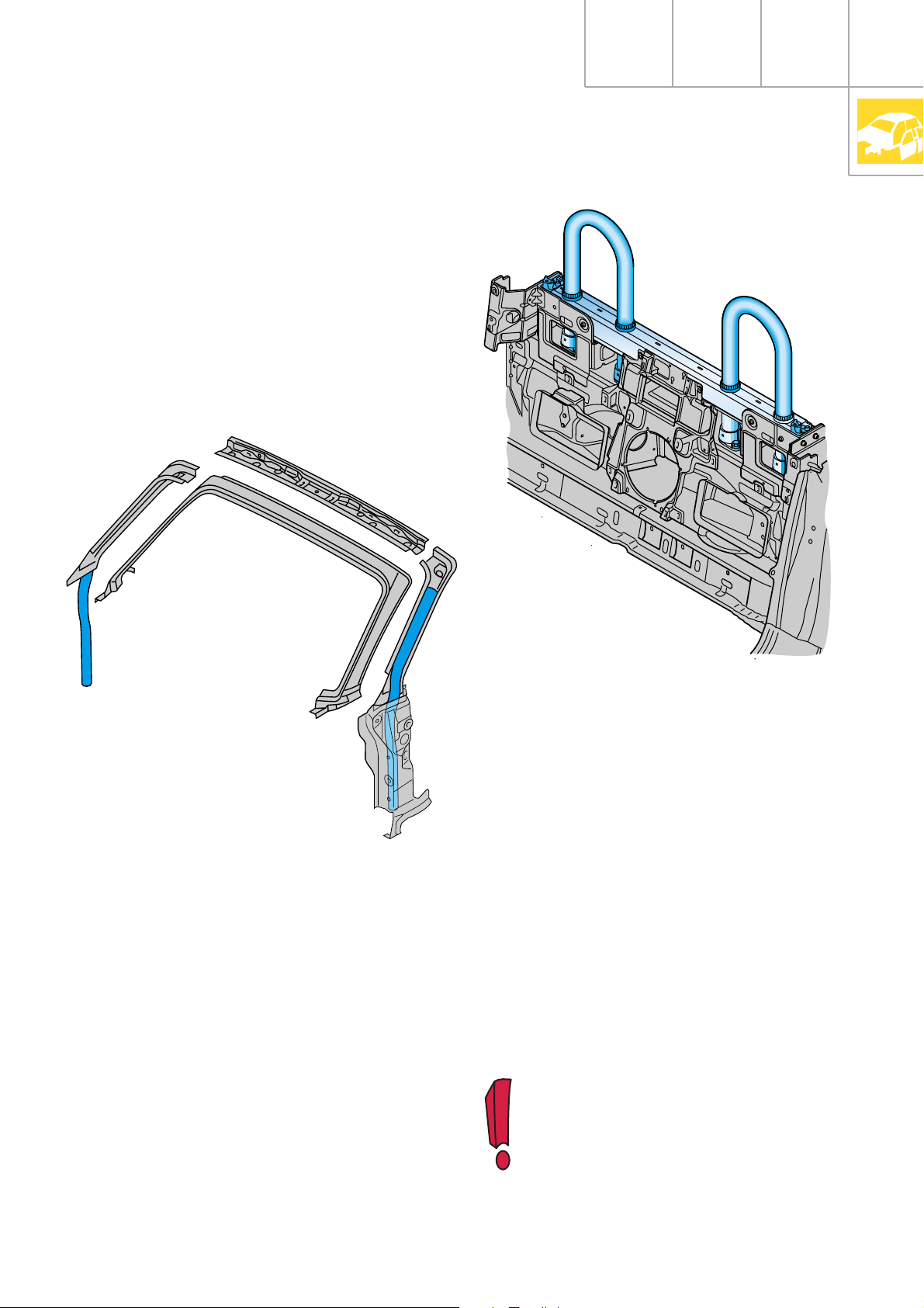
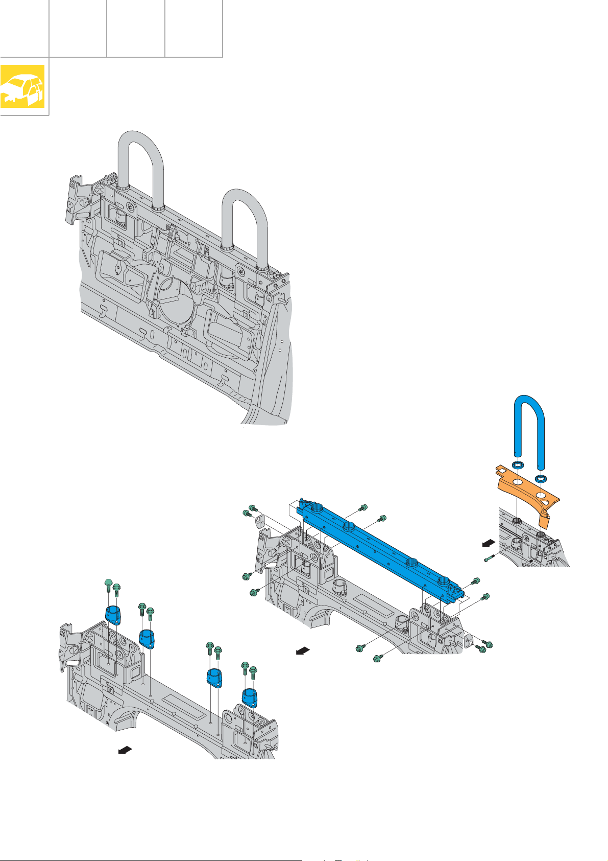
Occupant protection
Despite the lack of a roof structure, the
convertible driver is provided with sufficient
protection in the event of a rollover, and a
saloon-like survival space is preserved.
The conceptual drawback of open-top convertibles is offset in the Audi TT roadster by a
highly effective and yet exceedingly aesthetic
solution.
Two roll bars anchored to the vehicle body
and projecting beyond the two head
restraints, in combination with the ultra-rigid
A pillar / windscreen cross-member combination, afford the vehicle occupants highly
effective protection even in the event of a
rollover.
SSP220_003
SSP220_004
The A pillar comprises a pipe-in-pipe system
reinforced with high-tensile steel.
In addition, tubular aluminium roll bars
adapted from the body contours of the
vehicle occupants give the roadster a special,
sporty look.
You can find information regarding further occupant protection measures in
SSP 207.
7
Page 8
Body
Gantry gauge
1
12
3
4
5
11
10
9
6
8
7
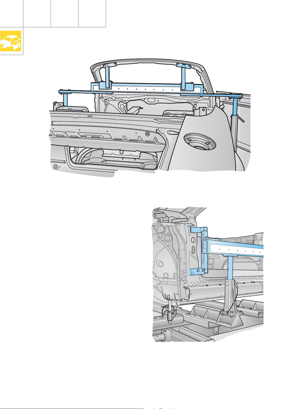
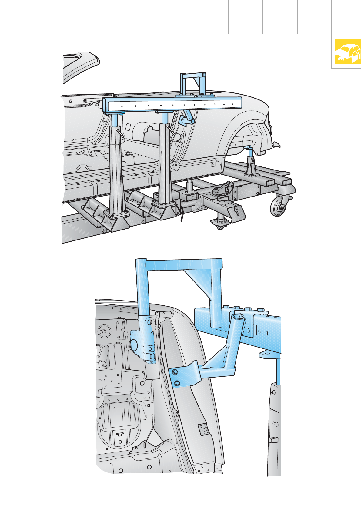
As with the Audi TT Coupé, the alignment
bracket set VAS 5020/6 is also used in the
Audi TT roadster.
In connection with the known gantry gauge
VAS 5007, the TT roadster requires alignment
bracket set supplement VAS 5007/8.
The following locating points are measured:
7
8
9
6
5
10
4
3
12
2
1
SSP220_026
1
2
3
4
5
12
11
10
9
6
8
7
– Soft top locks at left/right on windscreen
frame
– A pillar
– Striker plate mount, B pillar
– Soft top main bearing mount, left/right
Correctly positioned on the vehicle body, the
locating points ensure an ideal soft top
geometry.
8
SSP220_025
Page 9
1
12
10
11
8
9
6
7
4
5
1
2
3
12
11
10
9
8
7
6
5
4
3
2
SSP220_023
SSP220_024
9
Page 10
30
40
50
60
90
°C
50
70
13
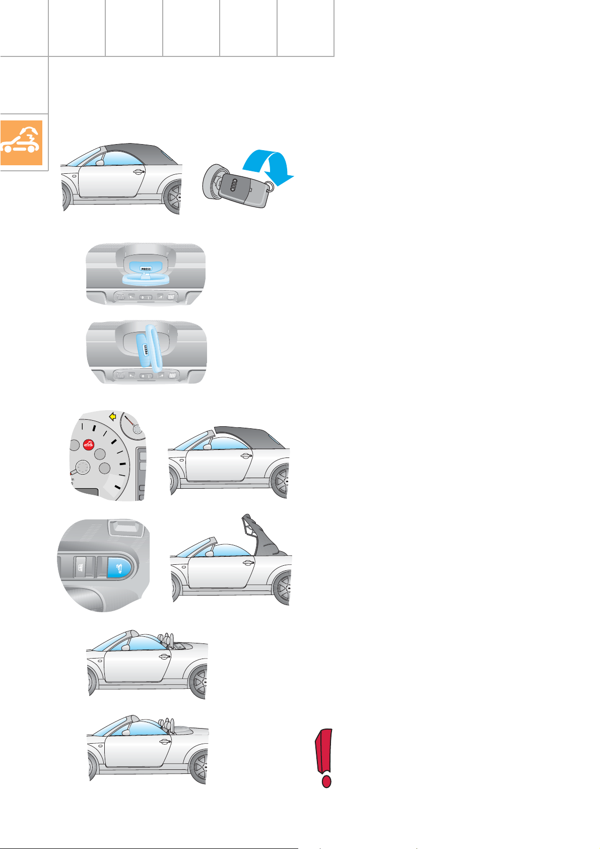
Soft top control
Semiautomatic soft top
Open soft top:
1.
– Vehicle stationary (< 5 kph)
– Ignition "On"
2.
– Press down the release knob and fold
down the locking handle.
3.
– Turn the handle anticlockwise as far as the
stop and push the soft top up out of the
interlock.
(turn back handle and fold in)
4.
– The warning lamp for the soft top comes
on, and the door window panes are lowered automatically by approx. 30 mm.
5.
– Pull switch in central console.
– The soft top is opened and stowed in the
soft top box by means of two hydraulic
cylinders.
– The door window panes close automati-
cally.
– The warning lamp goes out.
6.
– Fit tonneau cover.
(refer to Operating Manual)
For safety reasons, the vehicle should
10
only be driven with the tonneau cover
fitted when the soft top is open.
Page 11

30
40
50
60
90
°C
50
70
13
Close soft top
1.
– Remove the tonneau cover and stow it
away in the luggage compartment.
(refer to Operating Manual)
2.
– Vehicle stationary (< 5 kph)
– Ignition "On"
When the tonneau cover is fitted, the
soft top function is deactivated or
disabled.
– Press down the switch in the central
console in order to close the soft top.
– The warning lamp for the soft top comes
on and the door window panes are
lowered automatically by approx. 30 mm.
3.
– Press down the release knob and fold
down the locking handle.
4.
– Turn the handle anticlockwise as far as the
stop, then pull the soft top down into the
lock and close.
– The door window panes close automati-
cally.
– The warning lamp goes out.
11
Page 12

Soft top control
Soft top design
Soft top fabric
Tension clamp
The weave and tensioning of the soft top
fabric are designed to maintain an air
stream for as long as possible.
The soft top fabric is secured to the
bracing hoops by tension clamps.
For visual reasons, these bracing hoops
have plastic linings.
Soft top frame
(mechanism)
Raising the front roof rail allows the soft
top to be stowed away in the soft top box
by means of a kinematic chain (roof links 1
and 2 plus the main link) . The tensioning
strut simultaneously folds down from its
“stretched” position into the stowed
position in the soft top box.
Hydraulic cylinder with main bearing
Front roof rail
SSP220_046
Roof link 1
12
Guide part
For better stowage of the soft top, there
is a guide part on the tensioning strut at
the point of anchoring to the main
bearing.
SSP220_047
Page 13

Tonneau cover
Use the tonneau cover to protect the
stowed soft top.
Bracing hoop 1
Roof link 2
Bracing hoop 2
Bracing hoop 3
SSP220_020
Bracing hoop 4
Main link
Main bearing
Tension strap
Tensioning strut
SSP220_022
13
Page 14

Soft top control
Hydraulic diagram
Depending on the direction of rotation of the
electric motor, the rotor piston pump forces
oil through a 2-way valve into the corresponding pressure lines routed to the hydraulic
cylinders.
"Open“ soft top
To open the soft top, the extended piston
rods are pushed back into the hydraulic
cylinder and the soft top is opened via the
main bearing.
"Close“ soft top
SSP220_005
14
To close the soft top, the piston rods are pushed
out of the cylinders and the soft top is closed via
the main bearing.
SSP220_006
Page 15

Position "soft top stowed“
Double-action, bidirectional hydraulic
cylinder.
Limit switch
Fuse
Sealing ring
Hydraulic line
connection
Hydraulic cylinder
Coil spring
Piston base
Piston rod
Hydraulic line
connection
Fuse
SSP220_007
15
Page 16

Soft top control
Hydraulic pump unit
2/2-way valve
Hydraulic pump
Electric motor
Changeover relay
Hydraulic pump
The pump is designed as a rotor piston pump.
The pump draws hydraulic fluid out of the
tank through bore E. The cylinders are filled
under the centrifugal force exerted by the
pistons.
The rotor, together with the pistons, rotates
around an excentrically mounted stator. Thus,
the pistons are pushed back in and the
hydraulic fluid is pumped through bore A into
the lines of the individual hydraulic cylinders
at a pressure not exceeding 100 bar.
Pressure line
"Close“
Rotor
SSP220_009
Pressure line
"Open“
Bore A
(pressure connection)
Pump housing
16
SSP220_053
Piston
Bore E
(suction connection)
Stator
SSP220_054
Page 17

Open soft top
Hydraulic cylinder
2/2-way valve
Hydraulic pump
Close soft top
Pressure limiting
valve
Pressure limiting
valve
SSP220_066
Expansion tank
Non-return valve
SSP220_065
17
Page 18

Soft top control
Fitting locations
Manual soft top
To enhance ease of use, the soft top is
equipped with two gas-filled springs which
make it easier to lift the soft top out of the the
soft top box. In addition, a set of compression
springs is installed in the main bearing (left/
right) in order to make the soft top easier to
open and close.
Central locking and anti-theft
alarm control unit J 379
Bulkhead (optional)
Microswitch
Soft top stowed
Microswitch
Soft top released
18
Page 19

Semiautomatic soft top
Hydraulic pump
Central locking and anti-theft
alarm control unit J 379
Hydr. cylinder
Microswitch
Soft top stowed
Microswitch
Tonneau cover, right
Soft top operating
switch
Bulkhead operating
switch
Microswitch
Tonneau cover, left
Soft top released
(autom. air conditioner off)
Soft top released
19
Page 20

Soft top control
Semiautomatic soft top
System overview
Ignition "On"
Road speed signal, dash panel
insert
Switch for soft top control
90
1/2
0
130
1/1
50
R
30
20
10
°C
40
50
60
70
80
100
120
70
60
140
160
50
40
180
200
30
220
20
240
10
260
0
Air conditioner operating and
display unit
(no automatic operation)
Microswitch
(Soft top released)
Microswitch
(soft top released)
Microswitch
(Soft top stowed)
Microswitch
(tonneau cover, left)
Operation
Operation
ECON
OTUA
OFF
Microswitch
(tonneau cover, right)
Hydraulic cylinder switch,
left
20
Page 21

30
40
50
60
90
°C
50
70
13
Central locking and anti-theft
alarm control unit J 379
Hydraulic pump
(with changeover relay)
Power windows
Soft top warning light
SSP220_059
21
Page 22

30
40
50
60
90
°C
50
70
13
Soft top control
Semiautomatic soft top
The soft top is controlled via central locking
control unit J379.
Self-diagnosis: Address word 35
Combination processor in instrument cluster
J218
90
1/2
0
130
30
20
10
50
40
50
60
70
1/1
°C
80
100
120
70
60
140
50
40
30
20
10
0
160
180
200
220
240
260
Signal utilisation:
Central locking control unit J379 receives the
vehicle road speed signal from the combination processor. This is a criterion for enabling
the switch for soft top operation at road
speeds of less than 5 kph.
Microswitch - soft top released
The left catch hook on the soft top operates
the microswitch integrated in the lock. This
signal is utilised for:
– Activating the soft top warning lamp
– Lowering the door window panes
(30 mm)
– Switching off the automatic air
conditioning mode
The signal supplied by the sender for interior
temperature sensor G65 in the air conditioner/Climatronic operating and display unit is
suppressed and the previously set temperature and fresh-air blower values are retained.
The short-stroke function (10 mm) for
raising and lowering the door window
panes is executed via the door contact
switch.
Microswitch - soft top released
The microswitch integrated in the right lock in
the windscreen frame closes as soon as the
22
centring pin leaves the lock when raising the
soft top. The second criterion for enabling the
switch for soft top control is fulfilled.
Page 23

Switch for soft top control
If the previous two criteria have been fulfilled,
the hydraulic pump is activated via central
locking control unit J379 when the soft top
switch is operated.
Microswitch - soft top stowed
(in the left-hand main bearing)
Signal utilisation:
– Switches the hydraulic pump off
– Rear window heating off
– Soft top warning light off
– Door window panes being raised
If the soft top is open and stored, the
short-stroke function is not executed
when opening and closing the doors.
Microswitch - tonneau cover, left/right
If the tonneau cover is fitted properly, the
microswitches are closed. The central locking
control unit uses this signal to suppress the
function of the switch for soft top operation.
Consequently, it is not possible to close the
soft top.
Switch at left-hand hydraulic cylinder
The switch closes as soon as the piston of the
hydraulic cylinder reaches the upper stop and
the soft top begins to close. The incoming
signal is utilised to switch off the hydraulic
pump.
Switch statuses can be exported to
measured value blocks 9 and 10 by
means of the Diagnostic Testing and
Information System.
23
Page 24

Soft top control
Function diagram
Semiautomatic soft top
E87 Signal for air conditioner
operating and display unit
(no automatic operation)
E137 Soft top operation button
F171 Soft top stowed switch
F172 Soft top released switch
F202 Soft top switch, front
F205 Soft top released switch
F254 Tonneau cover left switch
F267 Tonneau cover right switch
J321 Relay for hydraulic pump soft top
operation
J379 Central locking and
anti-theft alarm control unit
J531 Bulkhead control unit
K98 Soft top released warning lamp
N272 Solenoid valve for hydraulic pump
S Fuse
V118 Soft top hydraulic pump
30
X
31
in out
58s
01 10
E137
J379
1 Road speed signal from combination
processor in dash panel insert J218
24
1
K98
F267F254
31
Page 25

30
S
30
X
31
J321
M
N272
J379
V118
J531
E87
F205F202
F171 F172
31
SSP220_048
25
Page 26

Bulkhead
The bulkhead can only be raised if the soft top
is stowed;the latter is detected via the "Soft
top stowed“ microswitch.
Glass pane
Electric motor
SSP220_011
SSP220_036
26
Page 27

Function diagram
30
X
31
75x
S227
0110
J531
58s
in out
E278
J379
30
X
31
M
V186
31
E87
E278 Button for bulkhead operation
F171 Soft top stowed switch
F172 Soft top released switch
J379 Central locking and
anti-theft alarm control unit
J531 Bulkhead control unit
S227 Fuse
V186 Motor for bulkhead operation
F172
F171
31
SSP220_012
27
Page 28

Central locking
6-
DISK
Stowage compartment
The stowage compartment is locked and
unlocked by the central locking system.
SSP220_017
SSP220_016SSP220_015
28
Emergency release, luggage compartment
Operating the handle activates the luggage
compartment emergency release by means
of a bowden cable.
The compartment must be locked with the
ignition key.
CD changer tray
The CD changer tray is locked and released
by the central locking system.
CD player optional
Page 29

Interior monitor
Megawave interior
monitor
R 900
J347
J347
R 900
SSP220_042
Audi has developed a new interior monitoring
system which is ideal for such open-topped
vehicles as the Audi TT Roadster.
The system requirement is a precisely
demarcated theoretical "protective sheath“ in
the form of a hemispherical shell whose
intrusion is detectable at any time. However,
the system must not pick up movements
outside this protective sheath irrespective of
their velocity, object size and reflectivity.
SSP220_041
The radius of the "protective sheath“ is defined by the distance between the ultrasonic
sensor module and the shortest point within
the bounds of the vehicle.
The megawave interior protection
system is implemented by pulse radar.
29
Page 30

Interior monitor
Theoretical protective
sheath
When the system is active, the module
1
R = t
cyclically emits radar pulses with a very low
wattage (t
).
1
Pulse generator
t
= t
1
2
< t
t
1
2
t
2
J347
SSP220_043
do not activate alarm
1
R = t
t
2
J347
SSP220_044
activate alarm
The same pulse is supplied to a so-called
delay line within the control unit (t
).
2
A measuring process in parallel with actual
measurement in the defined vehicle interior is
therefore simulated.
If the propagation time of the radar pulse
from the transmitter antenna to the reflecting
object and back to the receiver antenna equates to at least the period set in the control
unit (t
), then the signal is evaluated in the
2
control unit and the alarm is triggered if
necessary.
30
The interior monitor can still be switched off
using the switch in the central console.
SSP220_014
Page 31

Dear Reader,
In this Self-Study Programme you will have been able to familiarise
yourself with the Audi TT Roadster.
Our objective is to make our Self-Study Programmes interesting
for you!
That is why we are giving you the opportunity to submit your views or
suggestions for future Self-Study Programmes.
To help you, we have provided the following questionnaire.
We will take into consideration suggestions sent to us under the fax
number +49 841/ 89-36367.
Thank you for your support.
With kind regards,
Service Technology TrainingTeam
31
Page 32

220
All rights reserved.
Technical specifications subject
to change without notice.
AUDI AG
Dept. I/VK-5
D-85045 Ingolstadt
Fax +49 841/89-36367
940.2810.39.20
Technical status 03/99
Printed in Germany
 Loading...