

Page 1
Protected by copyright. Copying for private or commercial purposes, in part or in whole, is not
permitted unless authorised by AUDI AG. AUDI AG does not guarantee or accept any liability
with respect to the correctness of information in this document. Copyright by AUDI AG.
Service
Workshop Manual
Audi TT 2007 ➤
4-cylinder direct petrol injection engine (2.0 ltr. 4-valve
turbo), mechanics
Engine ID
Edition 11.2006
BWA BPY
Service Department. Technical Information
Page 2
Protected by copyright. Copying for private or commercial purposes, in part or in whole, is not
permitted unless authorised by AUDI AG. AUDI AG does not guarantee or accept any liability
with respect to the correctness of information in this document. Copyright by AUDI AG.
Service
List of Workshop Manual Repair GroupsList of Workshop Manual
Repair GroupsList of Workshop Manual Repair Groups
Re pa ir G ro up
00 - Technical data
10 - Removing and installing engine
13 - Crankshaft group
15 - Cylinder head, valve gear
17 - Lubrication
19 - Cooling
21 - Turbocharging/supercharging
26 - Exhaust system
Technical information should always be available to the foremen and mechanics, because their
careful and constant adherence to the instructions is essential to ensure vehicle road-worthiness and
safety. In addition, the normal basic safety precautions for working on motor vehicles must, as a
matter of course, be observed.
All rights reserved.
No reproduction without prior agreement from publisher.
Copyright © 2010 Audi AG, Ingolstadt A005TT00520
Page 3
Protected by copyright. Copying for private or commercial purposes, in part or in whole, is not
permitted unless authorised by AUDI AG. AUDI AG does not guarantee or accept any liability
with respect to the correctness of information in this document. Copyright by AUDI AG.
Audi TT 2007 ➤
4-cylinder direct petrol injection engine (2.0 ltr. 4-valve turbo), mechanics - Edition 11.2006
Contents
00 - Technical data . . . . . . . . . . . . . . . . . . . . . . . . . . . . . . . . . . . . . . . . . . . . . . . . . . . . 1
1 Engine number . . . . . . . . . . . . . . . . . . . . . . . . . . . . . . . . . . . . . . . . . . . . . . . . . . . . . . . . . . 1
2 Engine data . . . . . . . . . . . . . . . . . . . . . . . . . . . . . . . . . . . . . . . . . . . . . . . . . . . . . . . . . . . . 2
3 Safety precautions . . . . . . . . . . . . . . . . . . . . . . . . . . . . . . . . . . . . . . . . . . . . . . . . . . . . . . . . 3
4 Rules for cleanliness . . . . . . . . . . . . . . . . . . . . . . . . . . . . . . . . . . . . . . . . . . . . . . . . . . . . . . 4
10 - Removing and installing engine . . . . . . . . . . . . . . . . . . . . . . . . . . . . . . . . . . . . . . 5
1 Removing and installing engine, detaching from gearbox . . . . . . . . . . . . . . . . . . . . . . . . . . 5
1.1 Removing engine . . . . . . . . . . . . . . . . . . . . . . . . . . . . . . . . . . . . . . . . . . . . . . . . . . . . . . . . 5
1.2 Separating engine and gearbox . . . . . . . . . . . . . . . . . . . . . . . . . . . . . . . . . . . . . . . . . . . . . . 18
1.3 Securing engine to assembly stand . . . . . . . . . . . . . . . . . . . . . . . . . . . . . . . . . . . . . . . . . . 20
1.4 Installing engine . . . . . . . . . . . . . . . . . . . . . . . . . . . . . . . . . . . . . . . . . . . . . . . . . . . . . . . . . . 21
2 Assembly mountings . . . . . . . . . . . . . . . . . . . . . . . . . . . . . . . . . . . . . . . . . . . . . . . . . . . . . . 25
2.1 Assembly mountings - exploded view . . . . . . . . . . . . . . . . . . . . . . . . . . . . . . . . . . . . . . . . 25
2.2 Checking adjustment of assembly mountings (engine/gearbox mountings) . . . . . . . . . . . . 26
2.3 Adjusting assembly mountings . . . . . . . . . . . . . . . . . . . . . . . . . . . . . . . . . . . . . . . . . . . . . . 27
13 - Crankshaft group . . . . . . . . . . . . . . . . . . . . . . . . . . . . . . . . . . . . . . . . . . . . . . . . . . 32
1 Cylinder block (pulley end) . . . . . . . . . . . . . . . . . . . . . . . . . . . . . . . . . . . . . . . . . . . . . . . . . . 32
1.1 Poly V-belt, bracket for ancillaries - exploded view . . . . . . . . . . . . . . . . . . . . . . . . . . . . . . 32
1.2 Removing and installing poly V-belt . . . . . . . . . . . . . . . . . . . . . . . . . . . . . . . . . . . . . . . . . . 33
1.3 Removing and installing bracket for ancillaries . . . . . . . . . . . . . . . . . . . . . . . . . . . . . . . . . . 35
1.4 Removing and installing vibration damper . . . . . . . . . . . . . . . . . . . . . . . . . . . . . . . . . . . . . . 38
1.5 Front sealing flange - exploded view . . . . . . . . . . . . . . . . . . . . . . . . . . . . . . . . . . . . . . . . . . 40
1.6 Renewing crankshaft oil seal - pulley end . . . . . . . . . . . . . . . . . . . . . . . . . . . . . . . . . . . . . . 41
1.7 Removing and installing sealing flange (front) . . . . . . . . . . . . . . . . . . . . . . . . . . . . . . . . . . 44
2 Cylinder block (gearbox end) . . . . . . . . . . . . . . . . . . . . . . . . . . . . . . . . . . . . . . . . . . . . . . . . 48
2.1 Rear sealing flange and dual-mass flywheel - exploded view . . . . . . . . . . . . . . . . . . . . . . 48
2.2 Removing and installing dual-mass flywheel . . . . . . . . . . . . . . . . . . . . . . . . . . . . . . . . . . . . 49
2.3 Removing and installing sealing flange (rear) . . . . . . . . . . . . . . . . . . . . . . . . . . . . . . . . . . 50
3 Crankshaft . . . . . . . . . . . . . . . . . . . . . . . . . . . . . . . . . . . . . . . . . . . . . . . . . . . . . . . . . . . . . . 53
3.1 Crankshaft - exploded view . . . . . . . . . . . . . . . . . . . . . . . . . . . . . . . . . . . . . . . . . . . . . . . . 53
3.2 Crankshaft dimensions . . . . . . . . . . . . . . . . . . . . . . . . . . . . . . . . . . . . . . . . . . . . . . . . . . . . 55
3.3 Measuring axial clearance of crankshaft . . . . . . . . . . . . . . . . . . . . . . . . . . . . . . . . . . . . . . 55
3.4 Measuring radial clearance of crankshaft . . . . . . . . . . . . . . . . . . . . . . . . . . . . . . . . . . . . . . 56
3.5 Extracting and driving in needle bearing for crankshaft . . . . . . . . . . . . . . . . . . . . . . . . . . . . 57
3.6 Removing and installing chain sprocket . . . . . . . . . . . . . . . . . . . . . . . . . . . . . . . . . . . . . . . . 58
4 Pistons and conrods - exploded view . . . . . . . . . . . . . . . . . . . . . . . . . . . . . . . . . . . . . . . . . . 60
4.1 Piston and cylinder dimensions . . . . . . . . . . . . . . . . . . . . . . . . . . . . . . . . . . . . . . . . . . . . . . 62
15 - Cylinder head, valve gear . . . . . . . . . . . . . . . . . . . . . . . . . . . . . . . . . . . . . . . . . . 63
1 Toothed belt drive . . . . . . . . . . . . . . . . . . . . . . . . . . . . . . . . . . . . . . . . . . . . . . . . . . . . . . . . 63
1.1 Toothed belt drive - exploded view . . . . . . . . . . . . . . . . . . . . . . . . . . . . . . . . . . . . . . . . . . . . 63
1.2 Removing and installing toothed belt . . . . . . . . . . . . . . . . . . . . . . . . . . . . . . . . . . . . . . . . . . 66
2 Cylinder head . . . . . . . . . . . . . . . . . . . . . . . . . . . . . . . . . . . . . . . . . . . . . . . . . . . . . . . . . . . . 77
2.1 Cylinder head - exploded view . . . . . . . . . . . . . . . . . . . . . . . . . . . . . . . . . . . . . . . . . . . . . . 77
2.2 Removing and installing inlet camshaft control valve 1 N205 . . . . . . . . . . . . . . . . . . . . . . 80
2.3 Removing and installing cylinder head cover . . . . . . . . . . . . . . . . . . . . . . . . . . . . . . . . . . . . 82
2.4 Removing and installing cylinder head . . . . . . . . . . . . . . . . . . . . . . . . . . . . . . . . . . . . . . . . 85
2.5 Checking compression . . . . . . . . . . . . . . . . . . . . . . . . . . . . . . . . . . . . . . . . . . . . . . . . . . . . 95
3 Valve gear . . . . . . . . . . . . . . . . . . . . . . . . . . . . . . . . . . . . . . . . . . . . . . . . . . . . . . . . . . . . . . 98
Contents i
Page 4
Protected by copyright. Copying for private or commercial purposes, in part or in whole, is not
permitted unless authorised by AUDI AG. AUDI AG does not guarantee or accept any liability
with respect to the correctness of information in this document. Copyright by AUDI AG.
Audi TT 2007 ➤
4-cylinder direct petrol injection engine (2.0 ltr. 4-valve turbo), mechanics - Edition 11.2006
3.1 Valve gear - exploded view . . . . . . . . . . . . . . . . . . . . . . . . . . . . . . . . . . . . . . . . . . . . . . . . 98
3.2 Removing and installing camshaft adjuster . . . . . . . . . . . . . . . . . . . . . . . . . . . . . . . . . . . . 101
3.3 Removing and installing camshafts . . . . . . . . . . . . . . . . . . . . . . . . . . . . . . . . . . . . . . . . . . 103
3.4 Checking axial clearance of camshafts . . . . . . . . . . . . . . . . . . . . . . . . . . . . . . . . . . . . . . . . 107
3.5 Renewing valve stem oil seals . . . . . . . . . . . . . . . . . . . . . . . . . . . . . . . . . . . . . . . . . . . . . . 108
3.6 Checking valve guides . . . . . . . . . . . . . . . . . . . . . . . . . . . . . . . . . . . . . . . . . . . . . . . . . . . . 112
3.7 Renewing exhaust camshaft oil seal . . . . . . . . . . . . . . . . . . . . . . . . . . . . . . . . . . . . . . . . . . 114
17 - Lubrication . . . . . . . . . . . . . . . . . . . . . . . . . . . . . . . . . . . . . . . . . . . . . . . . . . . . . . 119
1 Oil pump and sump . . . . . . . . . . . . . . . . . . . . . . . . . . . . . . . . . . . . . . . . . . . . . . . . . . . . . . 119
1.1 Sump - exploded view . . . . . . . . . . . . . . . . . . . . . . . . . . . . . . . . . . . . . . . . . . . . . . . . . . . . 119
1.2 Removing and installing sump . . . . . . . . . . . . . . . . . . . . . . . . . . . . . . . . . . . . . . . . . . . . . . 120
1.3 Balance shaft assembly with oil pump - exploded view . . . . . . . . . . . . . . . . . . . . . . . . . . . . 125
1.4 Removing and installing balance shaft assembly with oil pump . . . . . . . . . . . . . . . . . . . . . . 127
2 Oil filter bracket and oil cooler . . . . . . . . . . . . . . . . . . . . . . . . . . . . . . . . . . . . . . . . . . . . . . 132
2.1 Oil filter bracket - exploded view . . . . . . . . . . . . . . . . . . . . . . . . . . . . . . . . . . . . . . . . . . . . 132
2.2 Draining oil filter housing . . . . . . . . . . . . . . . . . . . . . . . . . . . . . . . . . . . . . . . . . . . . . . . . . . 133
2.3 Removing and installing oil cooler . . . . . . . . . . . . . . . . . . . . . . . . . . . . . . . . . . . . . . . . . . . . 134
2.4 Removing and installing oil filter bracket . . . . . . . . . . . . . . . . . . . . . . . . . . . . . . . . . . . . . . 137
2.5 Checking oil pressure and oil pressure switch . . . . . . . . . . . . . . . . . . . . . . . . . . . . . . . . . . 141
19 - Cooling . . . . . . . . . . . . . . . . . . . . . . . . . . . . . . . . . . . . . . . . . . . . . . . . . . . . . . . . . . 143
1 Removing and installing parts of cooling system . . . . . . . . . . . . . . . . . . . . . . . . . . . . . . . . 143
1.1 Cooling system components (on engine) - exploded view . . . . . . . . . . . . . . . . . . . . . . . . . . 144
1.2 Continued coolant circulation pump V51 - exploded view . . . . . . . . . . . . . . . . . . . . . . . . . . 145
1.3 Diagram of coolant hose connections . . . . . . . . . . . . . . . . . . . . . . . . . . . . . . . . . . . . . . . . 146
1.4 Draining and filling cooling system . . . . . . . . . . . . . . . . . . . . . . . . . . . . . . . . . . . . . . . . . . . . 147
1.5 Checking cooling system for leaks . . . . . . . . . . . . . . . . . . . . . . . . . . . . . . . . . . . . . . . . . . . . 151
1.6 Removing and installing coolant pipes . . . . . . . . . . . . . . . . . . . . . . . . . . . . . . . . . . . . . . . . 152
1.7 Removing and installing coolant distributor housing with map-controlled engine cooling
thermostat F265 . . . . . . . . . . . . . . . . . . . . . . . . . . . . . . . . . . . . . . . . . . . . . . . . . . . . . . . . 155
1.8 Removing and installing coolant pump . . . . . . . . . . . . . . . . . . . . . . . . . . . . . . . . . . . . . . . . 155
1.9 Radiator and radiator fans - exploded view . . . . . . . . . . . . . . . . . . . . . . . . . . . . . . . . . . . . 158
1.10 Removing and installing radiator . . . . . . . . . . . . . . . . . . . . . . . . . . . . . . . . . . . . . . . . . . . . 158
1.11 Removing and installing radiator cowl . . . . . . . . . . . . . . . . . . . . . . . . . . . . . . . . . . . . . . . . 161
1.12 Removing and installing radiator fan V7 and radiator fan 2 V177 . . . . . . . . . . . . . . . . . . . . 163
21 - Turbocharging/supercharging . . . . . . . . . . . . . . . . . . . . . . . . . . . . . . . . . . . . . . . . 164
1 Turbocharger . . . . . . . . . . . . . . . . . . . . . . . . . . . . . . . . . . . . . . . . . . . . . . . . . . . . . . . . . . . . 164
1.1 Fitting hose connections with plug-in connectors . . . . . . . . . . . . . . . . . . . . . . . . . . . . . . . . 164
1.2 Turbocharger - exploded view . . . . . . . . . . . . . . . . . . . . . . . . . . . . . . . . . . . . . . . . . . . . . . 165
1.3 Removing and installing turbocharger . . . . . . . . . . . . . . . . . . . . . . . . . . . . . . . . . . . . . . . . 170
1.4 Checking vacuum unit for turbocharger . . . . . . . . . . . . . . . . . . . . . . . . . . . . . . . . . . . . . . . . 177
1.5 Removing and installing vacuum unit for turbocharger . . . . . . . . . . . . . . . . . . . . . . . . . . . . 179
1.6 Adjusting vacuum unit for turbocharger . . . . . . . . . . . . . . . . . . . . . . . . . . . . . . . . . . . . . . . . 179
2 Charge air system . . . . . . . . . . . . . . . . . . . . . . . . . . . . . . . . . . . . . . . . . . . . . . . . . . . . . . . . 185
2.1 Charge air cooler - exploded view of components . . . . . . . . . . . . . . . . . . . . . . . . . . . . . . . . 185
2.2 Turbocharging diagram . . . . . . . . . . . . . . . . . . . . . . . . . . . . . . . . . . . . . . . . . . . . . . . . . . . . 186
2.3 Removing and installing charge air cooler . . . . . . . . . . . . . . . . . . . . . . . . . . . . . . . . . . . . . . 186
2.4 Checking charge air system for leaks . . . . . . . . . . . . . . . . . . . . . . . . . . . . . . . . . . . . . . . . 187
26 - Exhaust system . . . . . . . . . . . . . . . . . . . . . . . . . . . . . . . . . . . . . . . . . . . . . . . . . . 190
1 Parts of exhaust system . . . . . . . . . . . . . . . . . . . . . . . . . . . . . . . . . . . . . . . . . . . . . . . . . . . . 190
1.1 Exhaust system - exploded view . . . . . . . . . . . . . . . . . . . . . . . . . . . . . . . . . . . . . . . . . . . . 190
1.2 Removing and installing front exhaust pipe with catalytic converters and front silencer . . 191
1.3 Aligning exhaust system . . . . . . . . . . . . . . . . . . . . . . . . . . . . . . . . . . . . . . . . . . . . . . . . . . . . 194
ii Contents
Page 5
Protected by copyright. Copying for private or commercial purposes, in part or in whole, is not
permitted unless authorised by AUDI AG. AUDI AG does not guarantee or accept any liability
with respect to the correctness of information in this document. Copyright by AUDI AG.
Audi TT 2007 ➤
4-cylinder direct petrol injection engine (2.0 ltr. 4-valve turbo), mechanics - Edition 11.2006
1.4 Checking exhaust system for leaks . . . . . . . . . . . . . . . . . . . . . . . . . . . . . . . . . . . . . . . . . . 195
Contents iii
Page 6

Protected by copyright. Copying for private or commercial purposes, in part or in whole, is not
permitted unless authorised by AUDI AG. AUDI AG does not guarantee or accept any liability
with respect to the correctness of information in this document. Copyright by AUDI AG.
Audi TT 2007 ➤
4-cylinder direct petrol injection engine (2.0 ltr. 4-valve turbo), mechanics - Edition 11.2006
iv Contents
Page 7
Protected by copyright. Copying for private or commercial purposes, in part or in whole, is not
permitted unless authorised by AUDI AG. AUDI AG does not guarantee or accept any liability
with respect to the correctness of information in this document. Copyright by AUDI AG.
4-cylinder direct petrol injection engine (2.0 ltr. 4-valve turbo), mechanics - Edition 11.2006
00 – Technical data
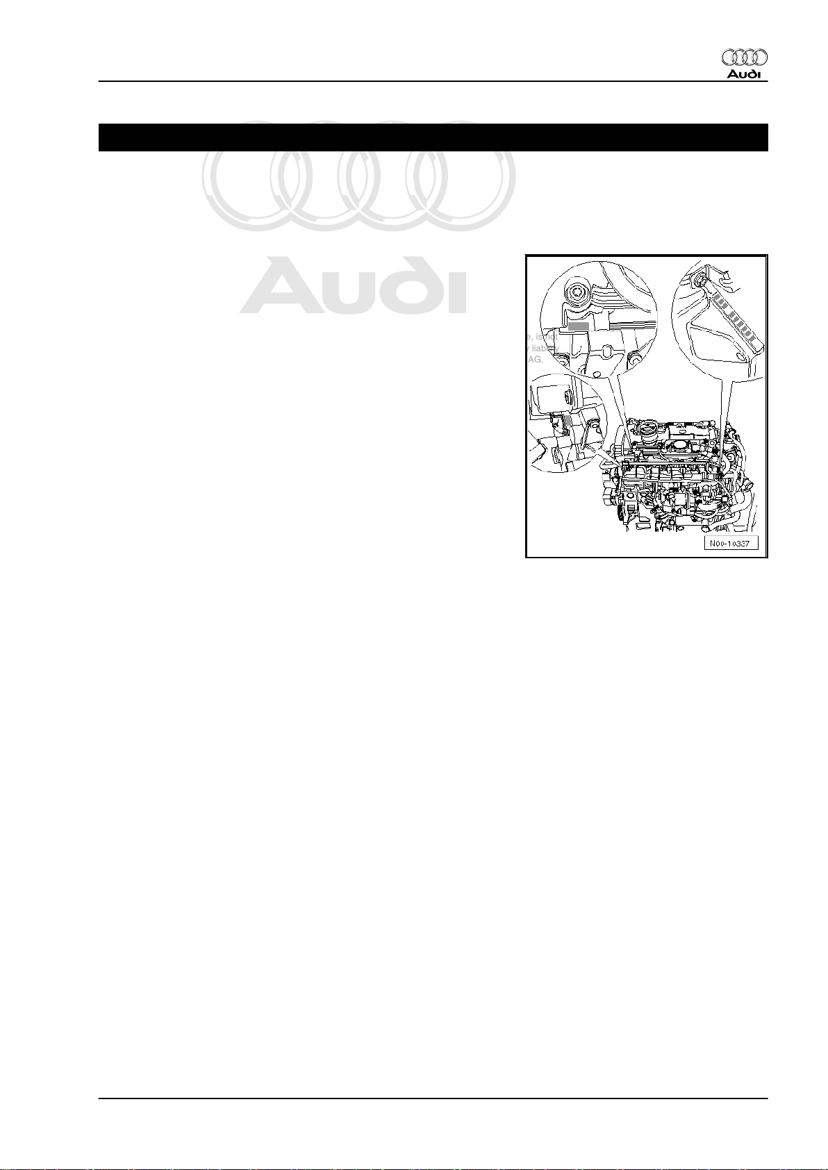
1 Engine number
The engine number (including “Engine code” and “Serial num‐
ber”) can be found on the left of the joint between engine and
gearbox.
The engine code is also stamped on the right of the cylinder head
and on the cylinder block.
The engine number consists of up to nine characters (alphanu‐
meric). The first part (up to 3 code letters) represents the “engine
code letters”, the second part (6 digits) the “serial number”. If more
than 999 999 engines were produced with the same code letters,
the first of the 6 digits is replaced by a letter.
Additionally there is a sticker on the toothed belt cover showing
the “engine code” and “serial number”.
The engine code is also to be found on the vehicle data sticker.
Audi TT 2007 ➤
1. Engine number 1
Page 8
Protected by copyright. Copying for private or commercial purposes, in part or in whole, is not
permitted unless authorised by AUDI AG. AUDI AG does not guarantee or accept any liability
with respect to the correctness of information in this document. Copyright by AUDI AG.
Audi TT 2007 ➤
4-cylinder direct petrol injection engine (2.0 ltr. 4-valve turbo), mechanics - Edition 11.2006
2 Engine data
Code letters BWA BPY
Capacity ltr. 1.984 1.984
Power output kW at rpm 147/5100 147/5700
Torque Nm at rpm 280/1800 280/2000
Bore ∅ in mm 82.5 82.5
Stroke mm 92.8 92.8
Compression ratio 10.3 10.5
RON
98
1)
Injection/ignition system FSI FSI
Firing order
1-3-4-2 1-3-4-2
Knock control yes yes
Turbocharging/super‐
yes yes
charging
Exhaust gas recirculation no no
Intake manifold change-
no no
over
Variable valve timing yes yes
Secondary air system no no
1)
•
Unleaded petrol RON 95 can also be used, but results in
reduced power
98
1)
2 Rep. Gr.00 - Technical data
Page 9
Protected by copyright. Copying for private or commercial purposes, in part or in whole, is not
permitted unless authorised by AUDI AG. AUDI AG does not guarantee or accept any liability
with respect to the correctness of information in this document. Copyright by AUDI AG.
4-cylinder direct petrol injection engine (2.0 ltr. 4-valve turbo), mechanics - Edition 11.2006
3 Safety precautions
When working on the fuel system please note the following warn‐
ings:
WARNING
The fuel system is pressurised. Before opening the system
place a clean cloth around the connection. Then release pres‐
sure by carefully loosening the connection.
Observe the following to avoid injuries to persons and/or damage
to the injection and ignition system:
♦ Always switch off the ignition before connecting or discon‐
necting electrical wiring for the injection or ignition system or
tester cables.
♦ Certain tests may lead to a fault being detected by the engine
control unit and stored in the memory. You must therefore in‐
terrogate the fault memory and erase it if necessary after
completion of all tests and repair work. If you erase the fault
memory, you must then generate the readiness code in the
engine control unit in “Guided Fault Finding” mode ⇒ Vehicle
diagnosis, testing and information system VAS 5051.
♦ Always switch off the ignition before cleaning the engine.
Audi TT 2007 ➤
♦ Observe notes on procedure for disconnecting the battery
Caution
⇒ Rep. Gr. 27 .
♦ Always switch off the ignition before connecting or dis‐
connecting the battery, otherwise the engine control unit
may be damaged.
When working on the cooling system note the following warnings:
WARNING
Hot steam or hot coolant can escape when expansion tank is
opened; cover filler cap with cloth and open carefully.
Note the following if testers and measuring instruments have to
be used during a road test:
WARNING
♦ Test equipment must always be secured on the rear seat
and operated from that position by a second person.
♦ If test and measuring instruments are operated from front
passenger's seat and the vehicle is involved in an acci‐
dent, the person sitting in this seat could be seriously
injured when the airbag is triggered.
3. Safety precautions 3
Page 10
Protected by copyright. Copying for private or commercial purposes, in part or in whole, is not
permitted unless authorised by AUDI AG. AUDI AG does not guarantee or accept any liability
with respect to the correctness of information in this document. Copyright by AUDI AG.
Audi TT 2007 ➤
4-cylinder direct petrol injection engine (2.0 ltr. 4-valve turbo), mechanics - Edition 11.2006
4 Rules for cleanliness
Injection system/fuel system
Even small amounts of dirt can cause faults in the injection sys‐
tem. When working on the fuel supply/injection system, please
pay careful attention to the following basic rules:
♦ Carefully clean connection points and the surrounding area
with engine cleaner or brake cleaner and dry thoroughly before
opening.
♦ Plug open lines and connections with suitable protective caps
immediately.
♦ Place parts that have been removed on a clean surface and
cover them over. Use only lint-free cloths.
♦ Only install clean components; replacement parts should only
be unpacked immediately prior to installation. Do not use parts
that have been previously unpacked and stored away loose
(e.g. in toolboxes, etc.).
♦ When the system is open: Do not work with compressed air.
Do not move the vehicle unless absolutely necessary.
♦ Unplugged electrical connectors must be kept clean and dry.
Make sure connections are dry when attaching.
Turbocharger
When working on the turbocharger, pay careful attention to the
following “5 rules”:
♦ Thoroughly clean all unions and surrounding areas before dis‐
connecting.
♦ Place parts that have been removed on a clean surface and
cover them over. Use only lint-free cloths.
♦ Carefully cover or seal open components if repairs cannot be
carried out immediately.
♦ Only install clean components; replacement parts should only
be unpacked immediately prior to installation. Do not use parts
that have been stored loose (e.g. in tool boxes etc.).
♦ When the system is open: Do not work with compressed air if
this can be avoided. Do not move the vehicle unless absolutely
necessary.
4 Rep. Gr.00 - Technical data
Page 11
Protected by copyright. Copying for private or commercial purposes, in part or in whole, is not
permitted unless authorised by AUDI AG. AUDI AG does not guarantee or accept any liability
with respect to the correctness of information in this document. Copyright by AUDI AG.
4-cylinder direct petrol injection engine (2.0 ltr. 4-valve turbo), mechanics - Edition 11.2006
10 – Removing and installing engine
1 Removing and installing engine, de‐
taching from gearbox
1.1 Removing engine
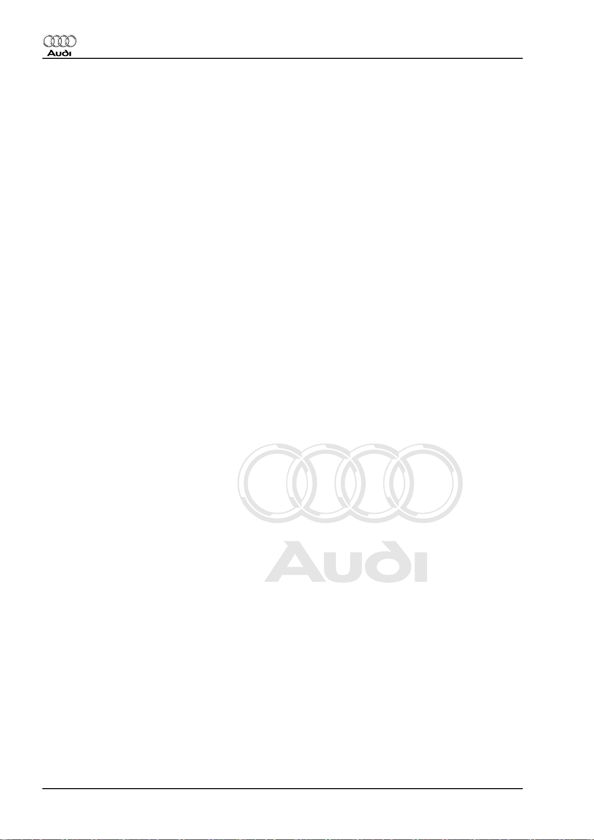
Special tools and workshop
equipment required
♦ Drip tray for workshop hoist
-VAS 6208-
♦ Engine and gearbox jack -
V.A.G 1383 A-
♦ Hose clip pliers -V.A.G
1921-
♦ Stepladder -VAS 5085-
♦ Engine bracket -T10012-
♦ Removal lever -80 - 200-
Audi TT 2007 ➤
1. Removing and installing engine, detaching from gearbox 5
Page 12
Protected by copyright. Copying for private or commercial purposes, in part or in whole, is not
permitted unless authorised by AUDI AG. AUDI AG does not guarantee or accept any liability
with respect to the correctness of information in this document. Copyright by AUDI AG.
Audi TT 2007 ➤
4-cylinder direct petrol injection engine (2.0 ltr. 4-valve turbo), mechanics - Edition 11.2006
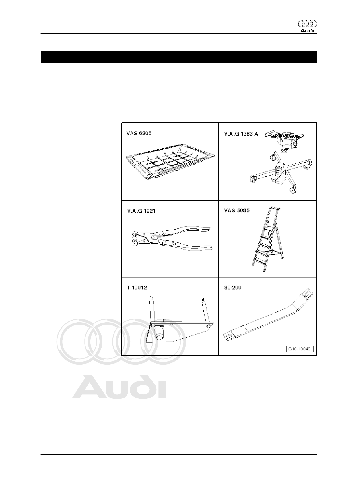
Lambda probe open ring spanner set -3337-
Engine bung set -VAS 6122-
Note
♦
The engine is removed from underneath together with the
gearbox.
♦
Renew all cable ties which are released or cut open when re‐
moving the engine. Refit in the same position when installing
the engine.
♦
Heat insulation sleeves removed when taking out the engine
are to be reinstalled in the original position.
♦
Collect drained coolant in a clean container for re-use or dis‐
posal.
WARNING
Observe notes on procedure for disconnecting the battery. ⇒
Electrical system; Rep. Gr. 27
– Remove luggage compartment floor covering.
– Release retaining clips -arrows- and detach cover for negative
terminal.
Note
Remove rear cross panel trim if cover for negative terminal of
battery is located under rear cross panel trim ⇒ Rep. Gr. 70 .
– With ignition switched off, disconnect earth wire -arrow- at
battery.
WARNING
Hot steam/hot coolant may escape when opening expansion
tank. Cover cap with cloth and open carefully.
– Open filler cap on coolant expansion tank
– Remove both front wheels.
6 Rep. Gr.10 - Removing and installing engine
Page 13
Protected by copyright. Copying for private or commercial purposes, in part or in whole, is not
permitted unless authorised by AUDI AG. AUDI AG does not guarantee or accept any liability
with respect to the correctness of information in this document. Copyright by AUDI AG.
4-cylinder direct petrol injection engine (2.0 ltr. 4-valve turbo), mechanics - Edition 11.2006
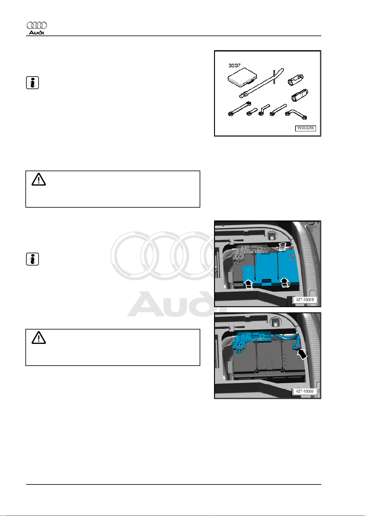
– Remove centre noise insulation -fasteners 1 ... 4-.
– Remove noise insulation panels (left and right) -arrows-.
Audi TT 2007 ➤
– Remove noise insulation frame -arrow-.
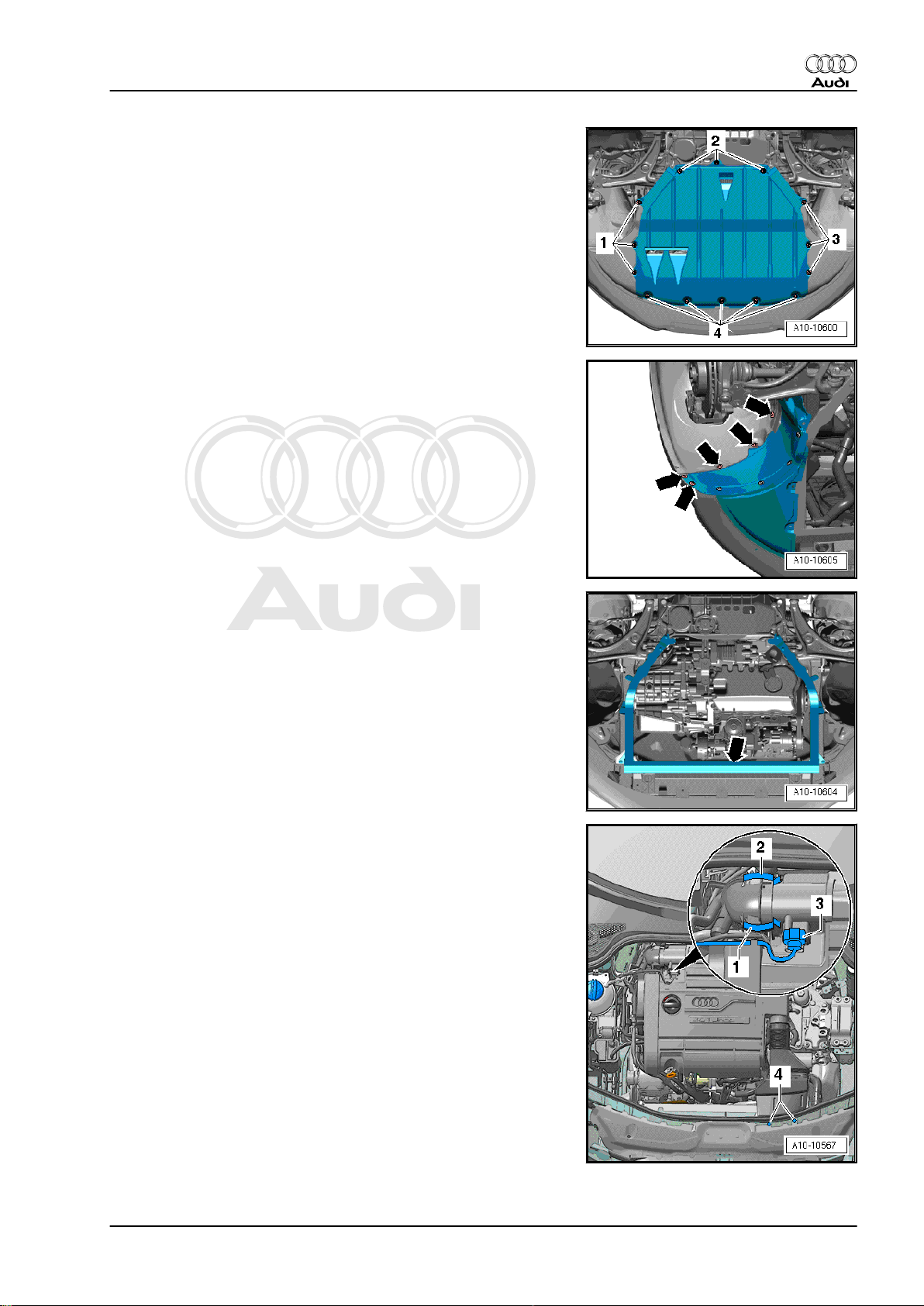
– Unplug electrical connector at air mass meter -G70- -3-.
– Open clamps -1 and 2- and disconnect air intake hose from
air mass meter.
– Detach air intake connection at lock carrier -4-.
– Pull off engine cover panel.
1. Removing and installing engine, detaching from gearbox 7
Page 14
Protected by copyright. Copying for private or commercial purposes, in part or in whole, is not
permitted unless authorised by AUDI AG. AUDI AG does not guarantee or accept any liability
with respect to the correctness of information in this document. Copyright by AUDI AG.
Audi TT 2007 ➤
4-cylinder direct petrol injection engine (2.0 ltr. 4-valve turbo), mechanics - Edition 11.2006
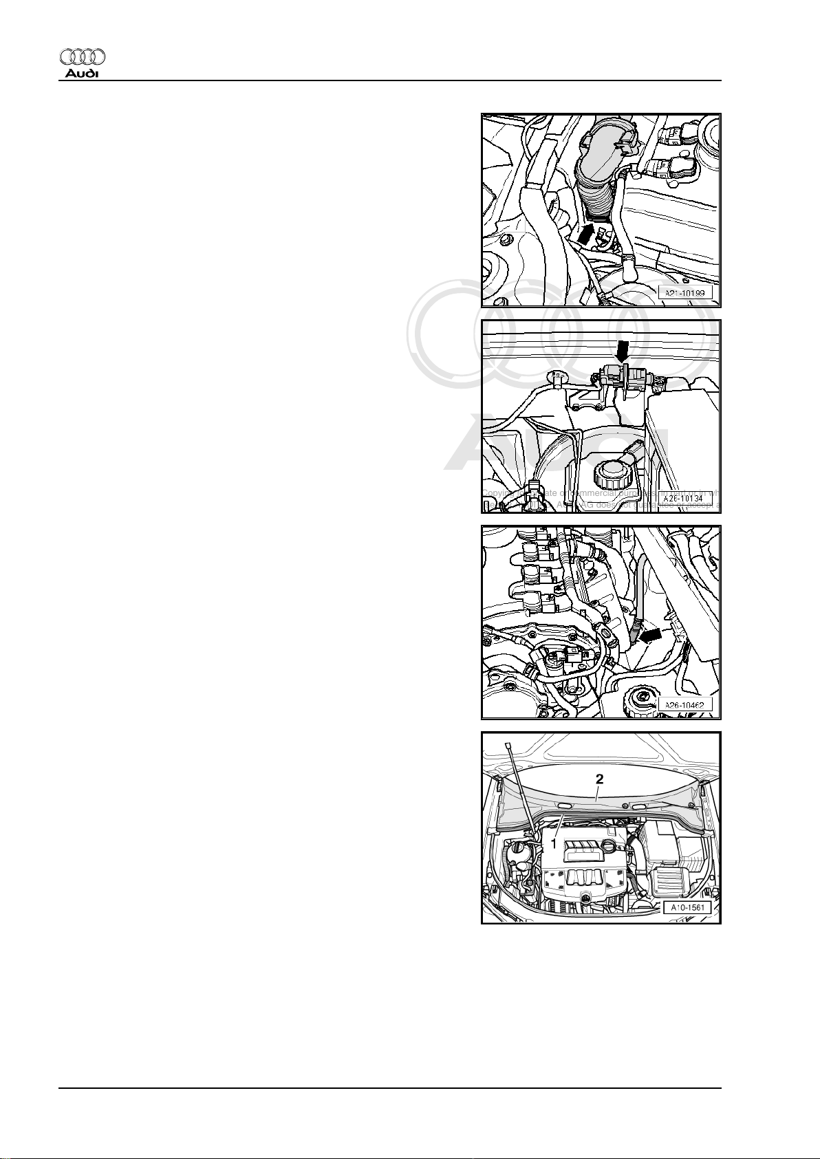
– Remove air intake hose -arrow- using hose clip pliers -V.A.G
1921- .
– Remove electrical connector -arrow- for Lambda probe (be‐
fore catalytic converter) from bracket, unplug and move clear.
– Unscrew Lambda probe -G39- -arrow- using tool from Lambda
probe open ring spanner set -3337- .
– Use screwdriver to pry off cover caps on wiper arms and un‐
screw hexagon nuts.
– Pull wiper arms off wiper shafts and remove.
– Pull off rubber seal -1- on plenum chamber cover.
– Detach plenum chamber cover -2-.
– Move engine wiring harness in plenum chamber clear.
– Remove engine control unit. ⇒ Rep. Gr. 24
8 Rep. Gr.10 - Removing and installing engine
Page 15
Protected by copyright. Copying for private or commercial purposes, in part or in whole, is not
permitted unless authorised by AUDI AG. AUDI AG does not guarantee or accept any liability
with respect to the correctness of information in this document. Copyright by AUDI AG.
4-cylinder direct petrol injection engine (2.0 ltr. 4-valve turbo), mechanics - Edition 11.2006
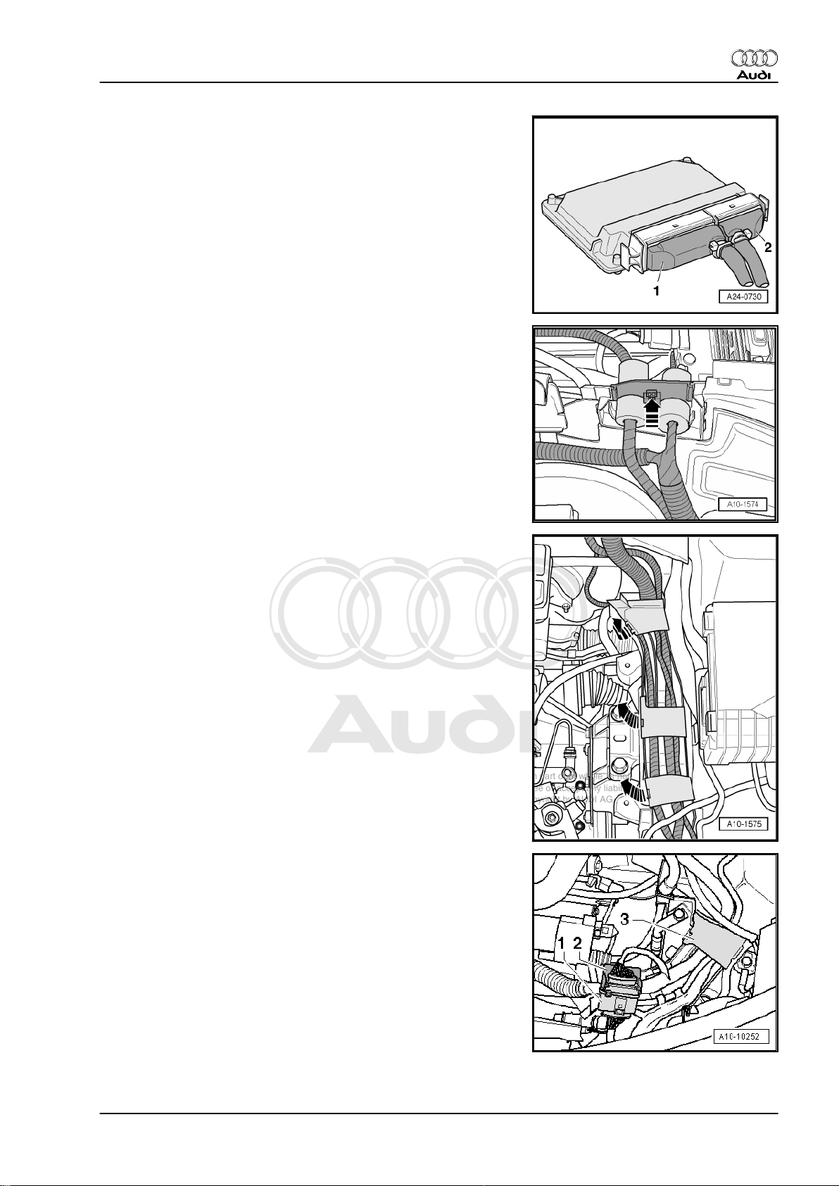
– Unplug engine wiring harness connector -1-.
– Release wiring protector for engine wiring harness -arrow- and
lift off.
Audi TT 2007 ➤
– Open wiring duct brackets -arrows-.
– Move electrical connector -1- clear and unplug connector.
– Open wiring duct bracket located below -2-.
– Open wiring duct bracket -3-.
– Remove engine control unit wiring harness from wiring duct.
1. Removing and installing engine, detaching from gearbox 9
Page 16
Protected by copyright. Copying for private or commercial purposes, in part or in whole, is not
permitted unless authorised by AUDI AG. AUDI AG does not guarantee or accept any liability
with respect to the correctness of information in this document. Copyright by AUDI AG.
Audi TT 2007 ➤
4-cylinder direct petrol injection engine (2.0 ltr. 4-valve turbo), mechanics - Edition 11.2006
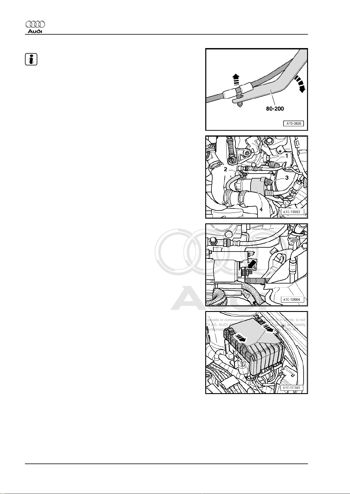
Note
Use removal lever -80 - 200- to lever out the wiring clips.
– Unplug electrical connector -1- for reversing light switch.
– Disconnect earth cable -2-.
– Unplug electrical connector -3-.
– Slide cover -4- to rear.
– Detach wire -arrow- at starter and move clear.
– Press the two clips in direction of the -arrows- and remove
cover from electronics box in engine compartment.
10 Rep. Gr.10 - Removing and installing engine
Page 17
Protected by copyright. Copying for private or commercial purposes, in part or in whole, is not
permitted unless authorised by AUDI AG. AUDI AG does not guarantee or accept any liability
with respect to the correctness of information in this document. Copyright by AUDI AG.
4-cylinder direct petrol injection engine (2.0 ltr. 4-valve turbo), mechanics - Edition 11.2006
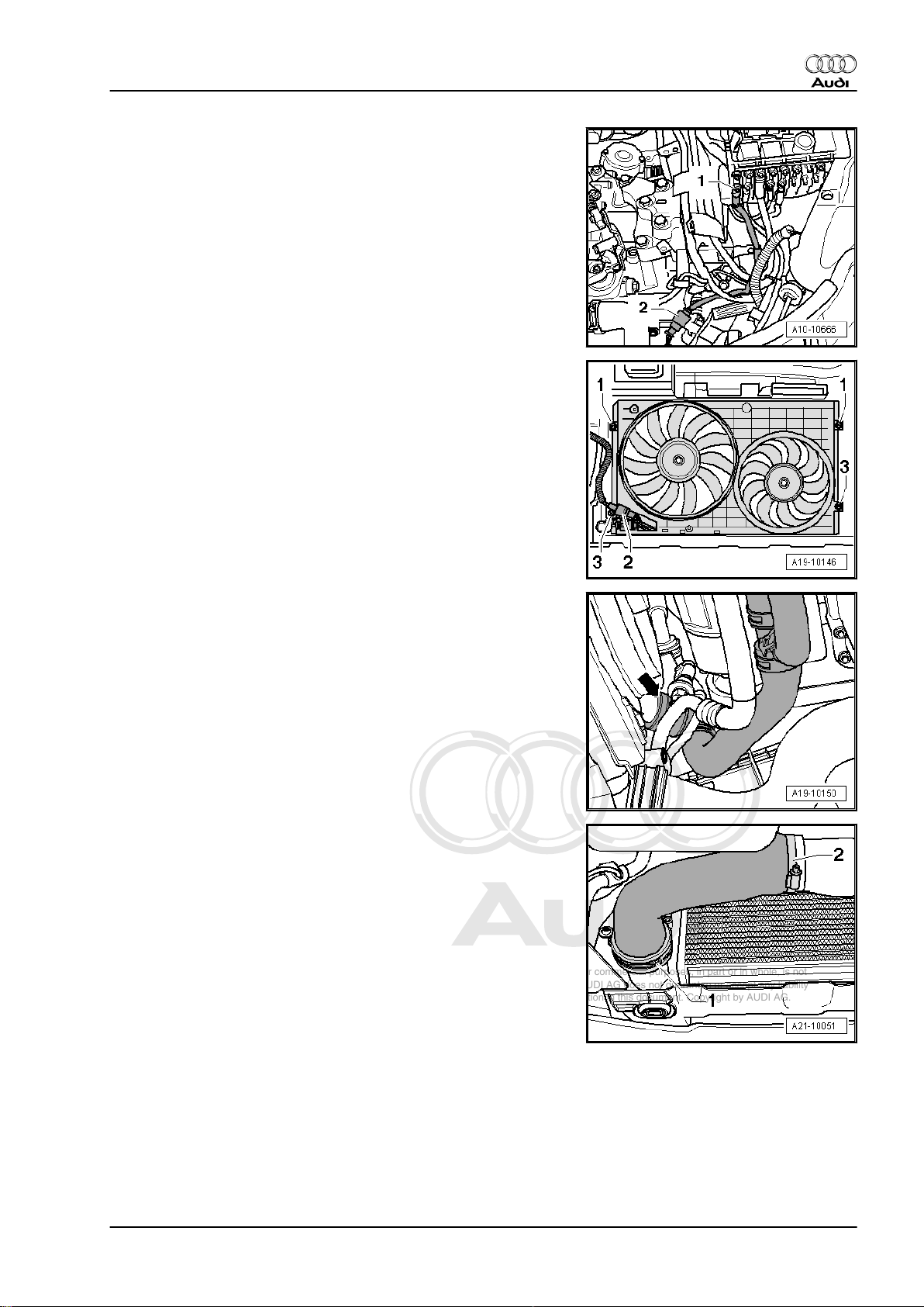
– Unscrew electrical wire -1- and move clear up to engine.
– Unplug electrical connector -2-.
– Unscrew bolts -1- from above.
Audi TT 2007 ➤
– Place drip tray for workshop hoist -VAS 6208- beneath engine.
– To drain off coolant, detach bottom coolant hose -arrow-.
– Remove air pipe -1 and 2- for charge air cooler.
1. Removing and installing engine, detaching from gearbox 11
Page 18
Protected by copyright. Copying for private or commercial purposes, in part or in whole, is not
permitted unless authorised by AUDI AG. AUDI AG does not guarantee or accept any liability
with respect to the correctness of information in this document. Copyright by AUDI AG.
Audi TT 2007 ➤
4-cylinder direct petrol injection engine (2.0 ltr. 4-valve turbo), mechanics - Edition 11.2006
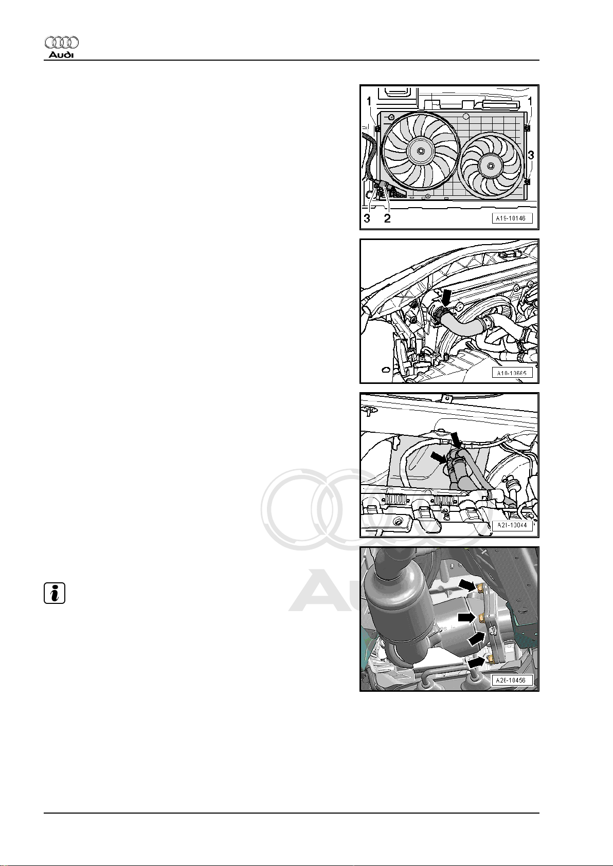
– Unplug electrical connector -2-.
– Unscrew the bolts -3- and remove radiator cowl from below.
– Detach top coolant hose from radiator -arrow-.
– Detach coolant hoses going to heat exchanger -arrows-.
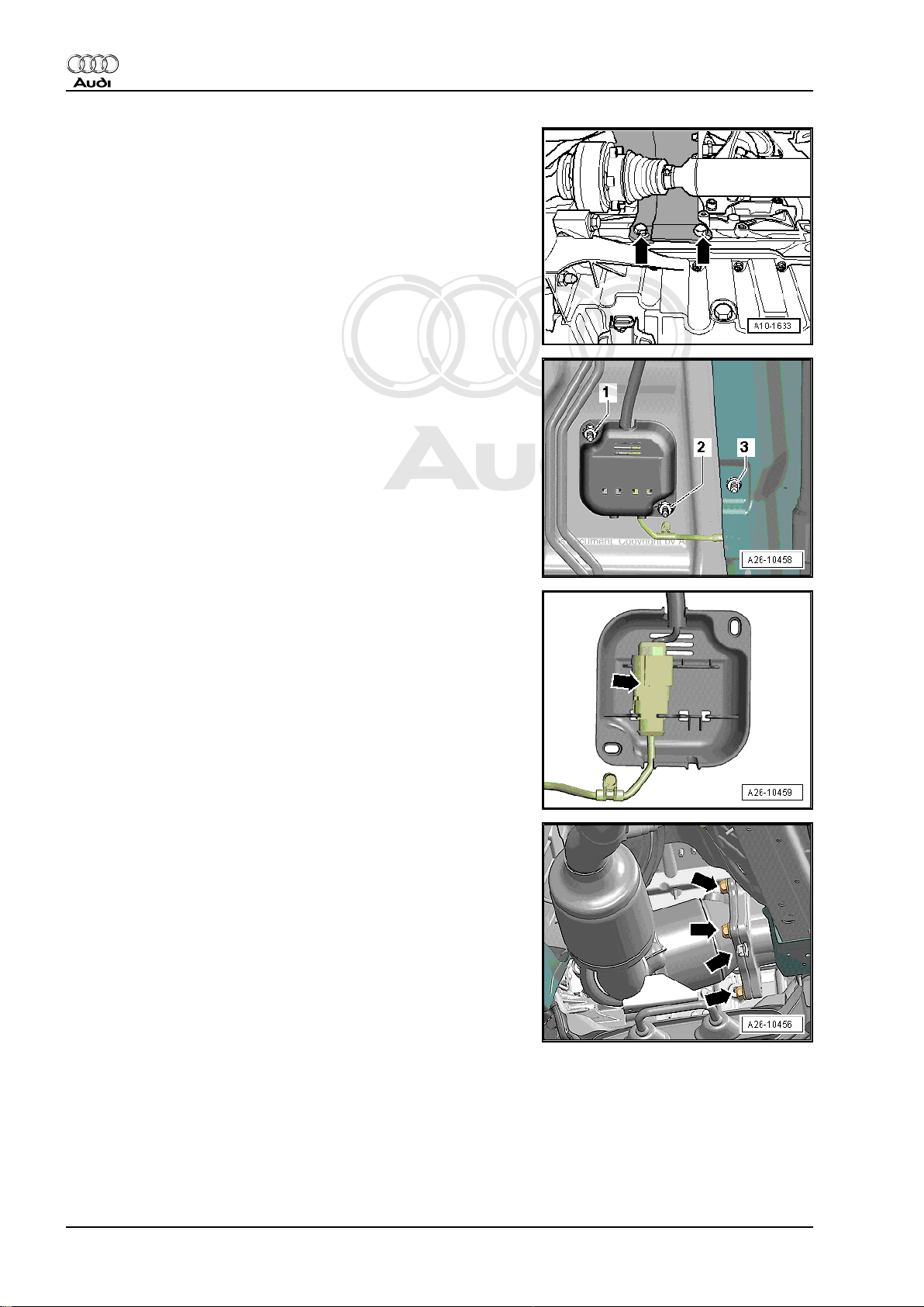
– Unscrew securing bolts -arrows- for front exhaust pipe/turbo‐
charger accessible from above.
Note
Shown in illustration from rear with engine removed.
12 Rep. Gr.10 - Removing and installing engine
Page 19
Protected by copyright. Copying for private or commercial purposes, in part or in whole, is not
permitted unless authorised by AUDI AG. AUDI AG does not guarantee or accept any liability
with respect to the correctness of information in this document. Copyright by AUDI AG.
4-cylinder direct petrol injection engine (2.0 ltr. 4-valve turbo), mechanics - Edition 11.2006
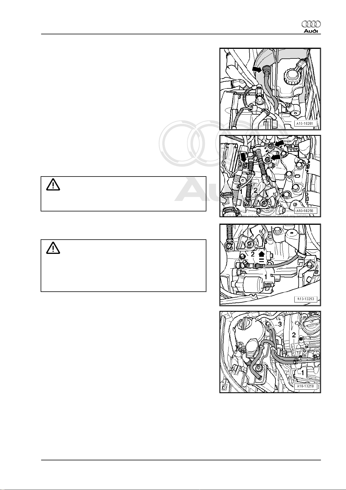
– Disconnect vacuum hose -arrow- leading to brake servo.
– Unclip securing clips -1- and -2- on both selector cables.
– Pull off selector cable end-pieces from gearbox selector lever
and relay lever.
– Detach cable support bracket from gearbox -arrows- and
place to one side.
WARNING
Audi TT 2007 ➤
Do not press clutch pedal after disconnecting hose leading to
slave cylinder.
– Pull out clip -2- as far a stop in -direction of arrow- and detach
hose -1-.
WARNING
Fuel supply line is pressurised. Wear safety goggles and pro‐
tective clothing to avoid possible injury and skin contact. Before
removing from hose connection wrap a cloth around the con‐
nection. Then release pressure by carefully pulling hose off
connection.
– Mark fuel line -2- and line going to ACF -1-.
– Disconnect fuel line -2- and move clear.
– Disconnect ACF line -1- and move clear.
– Disconnect vacuum line -3- going to activated charcoal filter
(press release tabs).
– Lift out ACF.
1. Removing and installing engine, detaching from gearbox 13
Page 20
Protected by copyright. Copying for private or commercial purposes, in part or in whole, is not
permitted unless authorised by AUDI AG. AUDI AG does not guarantee or accept any liability
with respect to the correctness of information in this document. Copyright by AUDI AG.
Audi TT 2007 ➤
4-cylinder direct petrol injection engine (2.0 ltr. 4-valve turbo), mechanics - Edition 11.2006
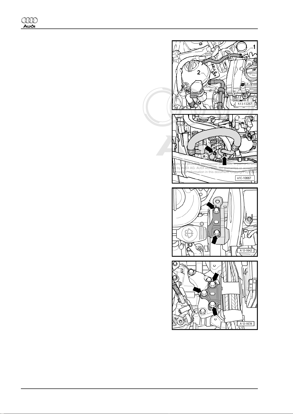
– Detach coolant hoses -1 and 2-.
– Discharge the refrigerant system ⇒ Rep. Gr. 87 ; Air condi‐
tioner system with refrigerant R134a .
– Disconnect air conditioner pipes -arrows- at compressor.
– Plug the openings with sealing plugs from engine bung set -
VAS 6122- .
– Loosen bolts -arrows- of assembly mounting for engine ap‐
prox. 2 turns.
– Loosen bolts -arrows- of assembly mounting for gearbox ap‐
prox. 2 turns.
14 Rep. Gr.10 - Removing and installing engine
Page 21
Protected by copyright. Copying for private or commercial purposes, in part or in whole, is not
permitted unless authorised by AUDI AG. AUDI AG does not guarantee or accept any liability
with respect to the correctness of information in this document. Copyright by AUDI AG.
4-cylinder direct petrol injection engine (2.0 ltr. 4-valve turbo), mechanics - Edition 11.2006
– Unplug electrical connector -arrow-.
– Remove air pipe -arrows-.
Audi TT 2007 ➤
– Unplug electrical connector -1- for high-pressure sender -
G65- .
– Detach air conditioner pipe from condenser -2-.
– Unplug electrical connector at oil level sender -1-.
– Unclip bracket -2-.
1. Removing and installing engine, detaching from gearbox 15
Page 22
Protected by copyright. Copying for private or commercial purposes, in part or in whole, is not
permitted unless authorised by AUDI AG. AUDI AG does not guarantee or accept any liability
with respect to the correctness of information in this document. Copyright by AUDI AG.
Audi TT 2007 ➤
4-cylinder direct petrol injection engine (2.0 ltr. 4-valve turbo), mechanics - Edition 11.2006
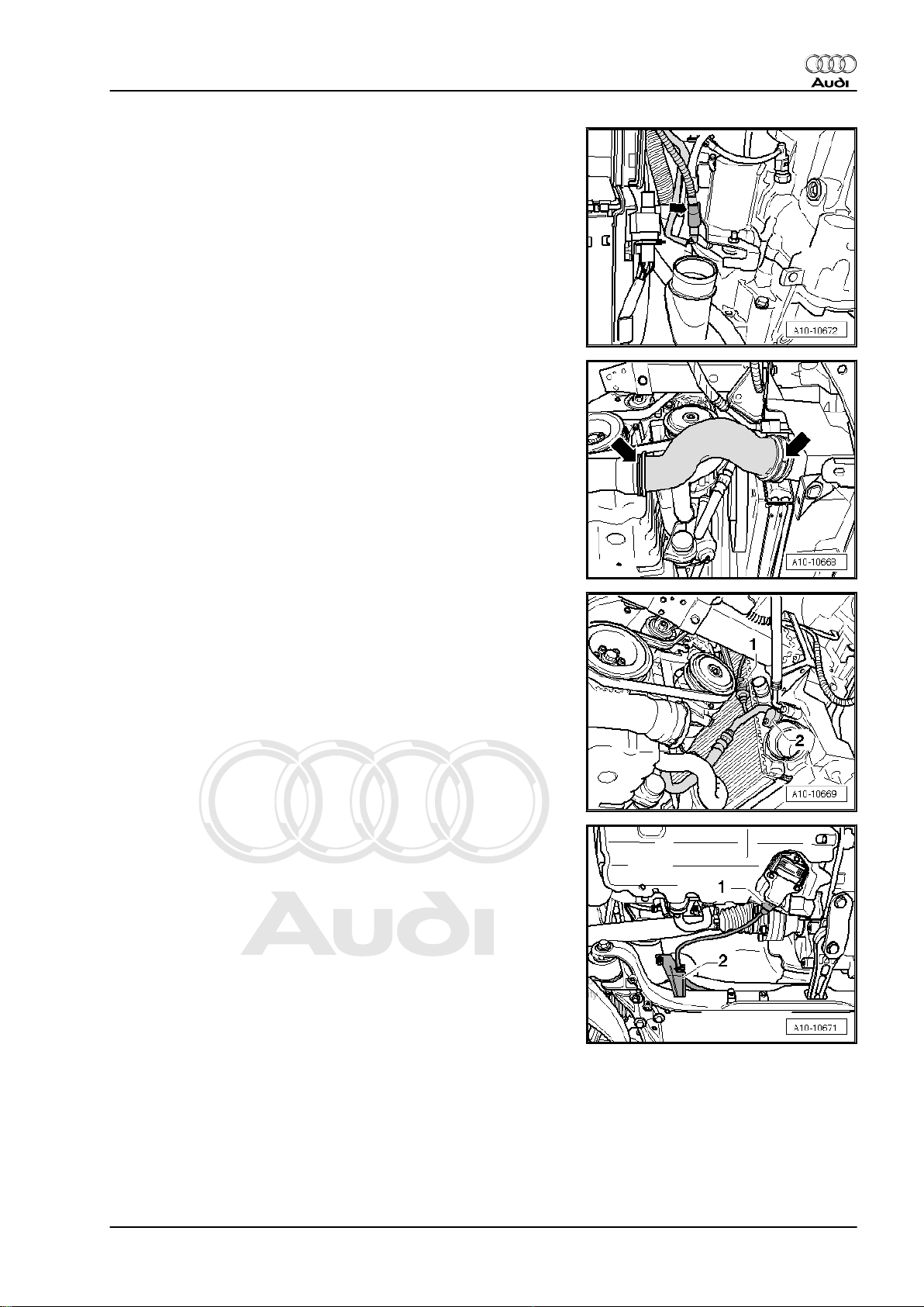
– Unbolt heat shield for drive shaft (right-side) -arrows-.
– Remove drive shafts (left and right) ⇒ Rep. Gr. 40 .
– Remove nuts -1- and -2- on bracket for electrical connector for
Lambda probe on underside of vehicle and remove cover.
– Unscrew bolt -3- and move electrical wire for Lambda probe
clear.
– Detach plug connector from bracket -arrow-.
– Unplug connector for Lambda probe after catalytic converter
-G130- .
– Unscrew remaining securing nuts -arrows- for front exhaust
pipe/turbocharger from below.
16 Rep. Gr.10 - Removing and installing engine
Page 23
Protected by copyright. Copying for private or commercial purposes, in part or in whole, is not
permitted unless authorised by AUDI AG. AUDI AG does not guarantee or accept any liability
with respect to the correctness of information in this document. Copyright by AUDI AG.
4-cylinder direct petrol injection engine (2.0 ltr. 4-valve turbo), mechanics - Edition 11.2006
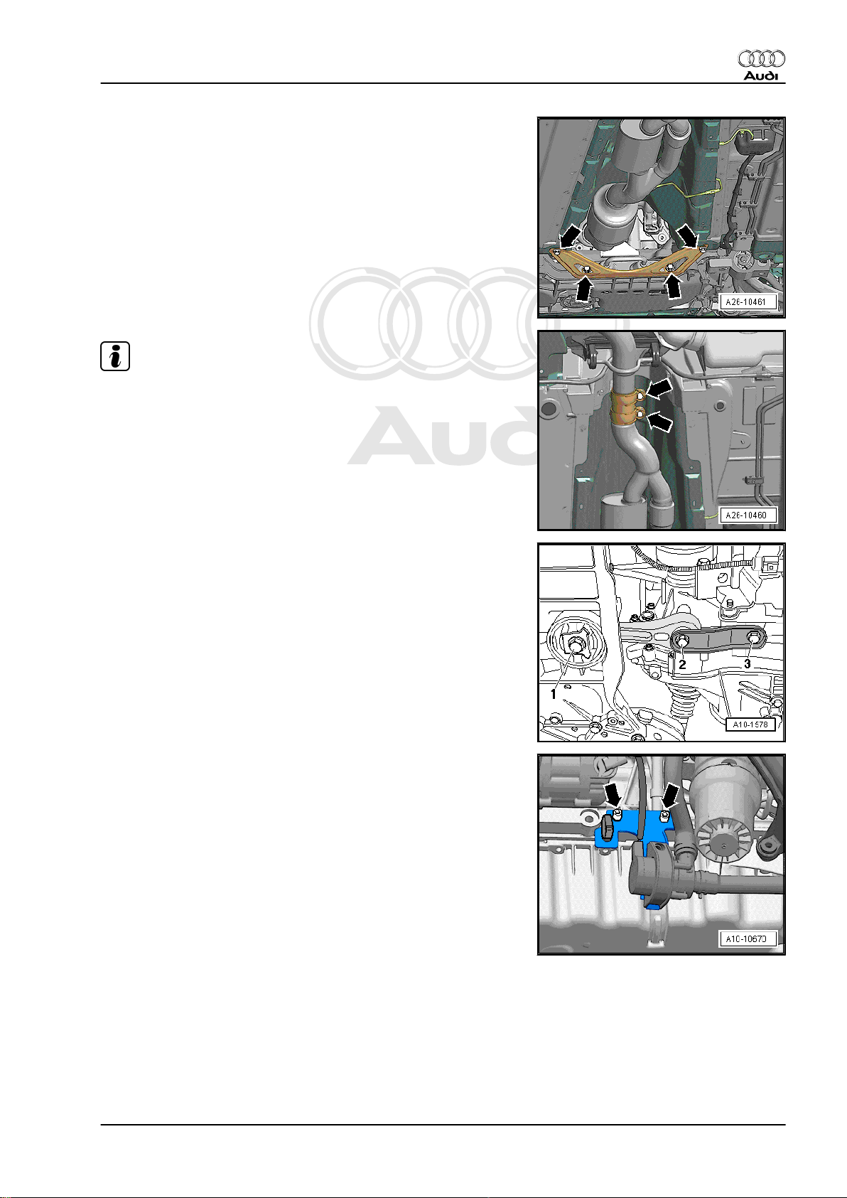
– Unbolt bracket for exhaust system and tunnel brace -arrows-.
Note
To avoid any damage, the flexible joint in the front exhaust pipe
must not be bent more than 10°.
– Separate exhaust system at clamp -arrows-.
– Remove front exhaust pipe with catalytic converter and front
silencer.
Audi TT 2007 ➤
– Remove bolts -1 ... 3- and take out pendulum support.
– Unscrew the additional coolant pump -arrows-.
1. Removing and installing engine, detaching from gearbox 17
Page 24
Protected by copyright. Copying for private or commercial purposes, in part or in whole, is not
permitted unless authorised by AUDI AG. AUDI AG does not guarantee or accept any liability
with respect to the correctness of information in this document. Copyright by AUDI AG.
Audi TT 2007 ➤
4-cylinder direct petrol injection engine (2.0 ltr. 4-valve turbo), mechanics - Edition 11.2006
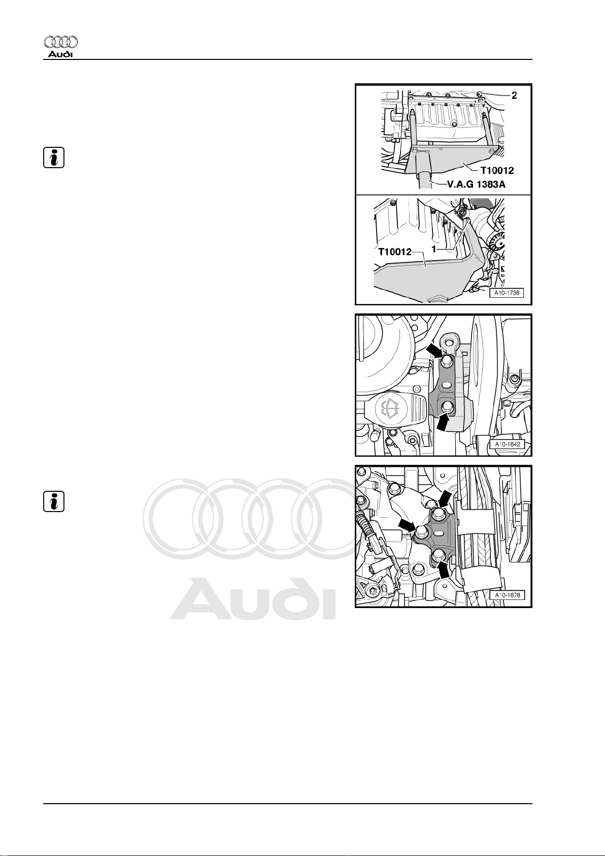
– Bolt engine bracket -T10012- with securing bolt -1- and nut
-2- to cylinder block (tightening torque: approx. 20 Nm).
– Insert engine and gearbox jack -V.A.G 1383 A- in engine
bracket -T10012- and raise engine slightly.
Note
To unscrew bolts for assembly mounting use stepladder -VAS
5085- .
– Remove bolts -arrows- of assembly mounting on engine.
– Remove bolts -arrows- of assembly mounting for gearbox.
Note
♦
Check that all hoses, pipes and wiring connections between
engine, gearbox and body have been detached.
♦
Carefully guide engine/gearbox assembly when lowering to
avoid damage.
– Pull engine/gearbox assembly as far forward as possible, and
lower gradually.
1.2 Separating engine and gearbox
• Engine/gearbox assembly removed and attached to engine
bracket -T10012- .
18 Rep. Gr.10 - Removing and installing engine
Page 25
Protected by copyright. Copying for private or commercial purposes, in part or in whole, is not
permitted unless authorised by AUDI AG. AUDI AG does not guarantee or accept any liability
with respect to the correctness of information in this document. Copyright by AUDI AG.
4-cylinder direct petrol injection engine (2.0 ltr. 4-valve turbo), mechanics - Edition 11.2006
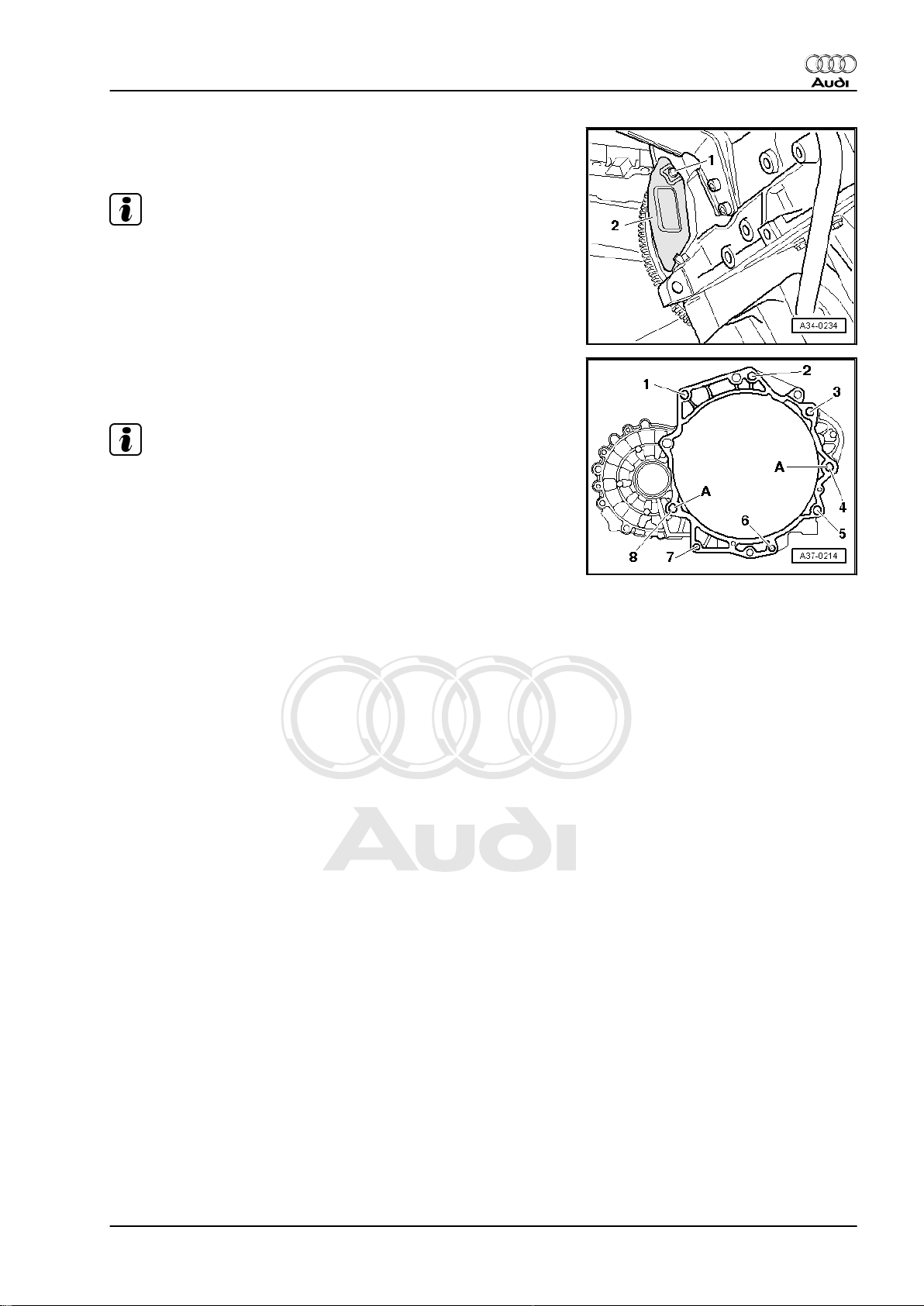
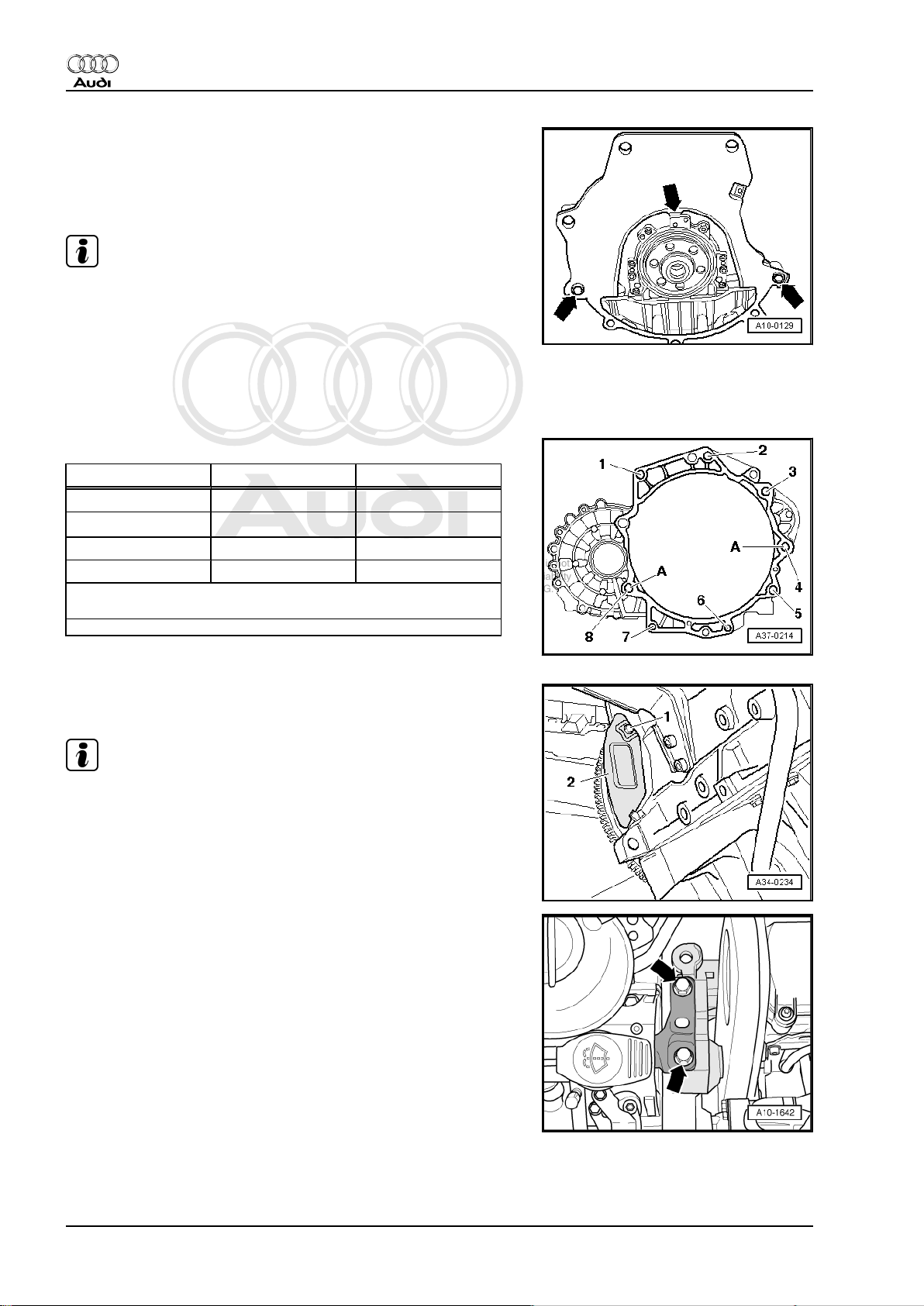
– Unscrew bolt -1- with gearbox installed.
– Pull up cover plate -2- and remove.
Note
Shown in illustration with gearbox removed.
– Remove bolts -1 ... 8- on engine/gearbox flange.
– Detach starter.
Note
The manual gearbox can be detached from the engine without a
workshop hoist, a 2nd mechanic is required for this purpose.
Audi TT 2007 ➤
– Separate gearbox from engine.
1. Removing and installing engine, detaching from gearbox 19
Page 26
Protected by copyright. Copying for private or commercial purposes, in part or in whole, is not
permitted unless authorised by AUDI AG. AUDI AG does not guarantee or accept any liability
with respect to the correctness of information in this document. Copyright by AUDI AG.
Audi TT 2007 ➤
4-cylinder direct petrol injection engine (2.0 ltr. 4-valve turbo), mechanics - Edition 11.2006
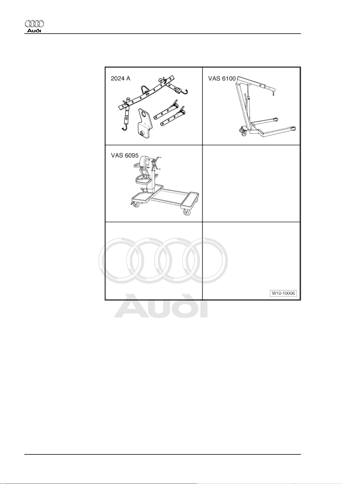
1.3 Securing engine to assembly stand
Special tools and workshop
equipment required
♦ Lifting tackle -2024 A-
♦ Workshop hoist -VAS
6100-
♦ Engine and gearbox sup‐
port -VAS 6095-
• Gearbox detached from engine.
20 Rep. Gr.10 - Removing and installing engine
Page 27
Protected by copyright. Copying for private or commercial purposes, in part or in whole, is not
permitted unless authorised by AUDI AG. AUDI AG does not guarantee or accept any liability
with respect to the correctness of information in this document. Copyright by AUDI AG.
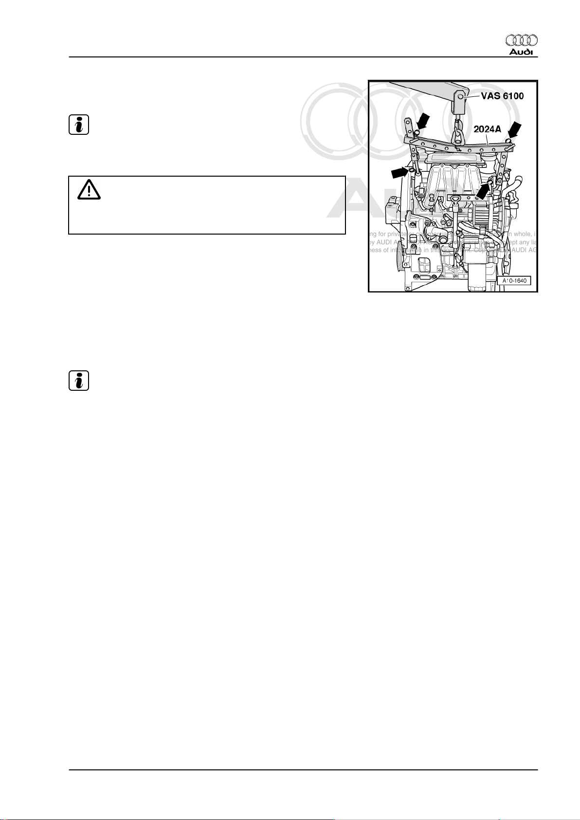
4-cylinder direct petrol injection engine (2.0 ltr. 4-valve turbo), mechanics - Edition 11.2006
– Engage lifting tackle -2024 A- on engine and workshop hoist
-VAS 6100- .
Note
To adjust to the centre of gravity of the assembly, the perforated
rails of the support hooks must be positioned as shown.
WARNING
The support hooks and locating pins on the lifting tackle must
be secured with locking pins (arrows in illustration).
– Lift engine off engine bracket -T10012- using workshop hoist
-VAS 6100- .
Secure engine to engine and gearbox support -VAS 6095- when
dismantling/assembling engine.
1.4 Installing engine
Audi TT 2007 ➤
• Engine installed on engine bracket -T10012- .
Installation is carried out in the reverse order; note the following:
Note
♦
Reinstall all cable ties in the same locations when assembling.
♦
Secure all hose connections with the correct type of hose clips
(same as original equipment): ⇒ Parts catalogue
♦
Renew self-locking nuts and bolts when performing assembly
work.
♦
Renew bolts which are tightened to a specified angle as well
as oil seals and gaskets.
♦
Clean input shaft splines and (in the case of used clutch plates)
the hub splines. Remove corrosion and apply only a very thin
coating of grease (⇒ Parts catalogue ) to the splines. Then
move clutch plate back and forth on input shaft until the hub
moves smoothly on the shaft. Remove any excess grease.
– Check whether dowel sleeves for centring the engine/gearbox
assembly are fitted in the cylinder block; install dowel sleeves
if necessary.
1. Removing and installing engine, detaching from gearbox 21
Page 28
Protected by copyright. Copying for private or commercial purposes, in part or in whole, is not
permitted unless authorised by AUDI AG. AUDI AG does not guarantee or accept any liability
with respect to the correctness of information in this document. Copyright by AUDI AG.
Audi TT 2007 ➤
4-cylinder direct petrol injection engine (2.0 ltr. 4-valve turbo), mechanics - Edition 11.2006
– Ensure that the intermediate plate is engaged on the sealing
flange and pushed onto the dowel sleeves -arrows-.
– Check clutch release bearing for wear; renew if necessary.
– Bolt gearbox to engine.
Note
♦
Tightening torques apply only to lightly greased, oiled,
phosphated or black-finished nuts and bolts.
♦
Additional lubricant such as engine oil or gearbox oil may be
used, but do not use lubricant containing graphite.
♦
Do not use degreased parts.
♦
Tolerance for tightening torques: 15%.
Securing engine to gearbox
Item Bolt Nm
1, 2 M12×65 80
3 1), 4
1)
M12×135 80
5 ... 7 M10×60 40
8 M12×90 65
1)
•
Bolt with M8 stud
A: Centring sleeves
– Push in splash plate -2- in such a way that the lower lug en‐
gages into the cylinder block and secure on top with bolt -1-.
Note
Shown in illustration with gearbox removed.
– Guide engine/gearbox assembly into the body.
– Tighten bolts -arrows- of assembly mounting for engine initially
hand-tight.
22 Rep. Gr.10 - Removing and installing engine
Page 29
Protected by copyright. Copying for private or commercial purposes, in part or in whole, is not
permitted unless authorised by AUDI AG. AUDI AG does not guarantee or accept any liability
with respect to the correctness of information in this document. Copyright by AUDI AG.
4-cylinder direct petrol injection engine (2.0 ltr. 4-valve turbo), mechanics - Edition 11.2006
– Tighten bolts of assembly mounting for gearbox -arrows- ini‐
tially hand-tight.
Note
♦
Use new securing bolts.
♦
The bolts are tightened to final torque only after adjusting the
engine mountings ⇒ page 25 .
– Remove engine bracket -T10012- from engine.
Audi TT 2007 ➤
1. Removing and installing engine, detaching from gearbox 23
Page 30
Protected by copyright. Copying for private or commercial purposes, in part or in whole, is not
permitted unless authorised by AUDI AG. AUDI AG does not guarantee or accept any liability
with respect to the correctness of information in this document. Copyright by AUDI AG.
Audi TT 2007 ➤
4-cylinder direct petrol injection engine (2.0 ltr. 4-valve turbo), mechanics - Edition 11.2006
– Secure pendulum support to gearbox and subframe -1 ... 3-.
– Install drive shafts ⇒ Running gear, front-wheel drive and four-
wheel drive; Repair group 40
– Install exhaust system and align it free of stress
⇒ page 194 .
– Install Lambda probe -G39- ⇒ Rep. Gr. 24 .
– Charge refrigerant circuit ⇒ Air conditioning system; Repair
group 87
– Attach and adjust selector mechanism at gearbox: ⇒ Rep. Gr.
34 .
– Adjust engine mountings ⇒ page 27 .
– Electrical connections and routing: ⇒ Current flow diagrams,
Electrical fault finding and Fitting locations
– Bleed fuel system ⇒ Motronic direct injection and ignition sys‐
tem (4-cylinder); Repair group 24; Servicing fuel injection sys‐
tem
– Check oil level ⇒ Maintenance ; Booklet 810 .
– Connect battery ⇒ Electrical system; Rep. Gr. 27 .
– Fill up with coolant ⇒ page 147 .
– Installing air pipes with connectors ⇒ page 164
Note
♦
Drained-off coolant may only be used again if the original cyl‐
inder head and cylinder block are re-installed.
♦
Contaminated or dirty coolant must not be used again.
WARNING
Never use battery charging equipment for boost starting. There
is danger of damaging the vehicle's control units.
Tightening torque
Component
Nm
Bolts/nuts M6 10
Except for the following:
Pendulum support to gearbox
Pendulum support to subframe
M8 20
M10 45
M12 65
40 + 90°
100 + 90°
1)2)
1)2)
Terminal B+ to starter 16
Earth wire to gearbox 23
1)
•
Renew bolt
2)
•
90° = one quarter turn.
24 Rep. Gr.10 - Removing and installing engine
Page 31

Protected by copyright. Copying for private or commercial purposes, in part or in whole, is not
permitted unless authorised by AUDI AG. AUDI AG does not guarantee or accept any liability
with respect to the correctness of information in this document. Copyright by AUDI AG.
4-cylinder direct petrol injection engine (2.0 ltr. 4-valve turbo), mechanics - Edition 11.2006
2 Assembly mountings
2.1 Assembly mountings - exploded view
1 - Bolt
❑ Gearbox support to
gearbox
❑ Tightening torque ⇒
Rep. Gr. 34
2 - Bolts
❑ Pendulum support to
gearbox
❑ Renew
❑
40 Nm + 90° (1/4 turn
further).
3 - Engine support
❑ With support arm
4 - Bolt
❑ Engine support to en‐
gine
❑ 45 Nm
5 - Engine mounting
6 - Bolt
❑ Engine mounting to
body
❑ Renew
❑
40 Nm + 90° (1/4 turn
further).
7 - Connecting bracket
8 - Bolt
❑ Connecting bracket to
engine mounting
❑ Renew
❑
20 Nm + 90° (1/4 turn
further).
9 - Bolt
❑ Connecting bracket to body
❑ Renew
❑
20 Nm + 90° (1/4 turn further).
Audi TT 2007 ➤
10 - Bolt
❑ Engine mounting to body
❑ Renew
❑
40 Nm + 90° (1/4 turn further).
11 - Bolts
❑ Engine mounting to engine support
❑ Renew
❑
60 Nm + 90° (1/4 turn further).
2. Assembly mountings 25
Page 32

Protected by copyright. Copying for private or commercial purposes, in part or in whole, is not
permitted unless authorised by AUDI AG. AUDI AG does not guarantee or accept any liability
with respect to the correctness of information in this document. Copyright by AUDI AG.
Audi TT 2007 ➤
4-cylinder direct petrol injection engine (2.0 ltr. 4-valve turbo), mechanics - Edition 11.2006
12 - Pendulum support
13 - Bolt
❑ Pendulum support to subframe
❑ Renew
❑
100 Nm + 90° (1/4 turn further).
14 - Bolt
❑ Gearbox mounting to gearbox support
❑ Tightening torque ⇒ Rep. Gr. 34
15 - Bolt
❑ Gearbox mounting to body
❑ Tightening torque ⇒ Rep. Gr. 34
16 - Gearbox mounting
❑ With support arm
17 - Bolt
❑ Gearbox support to gearbox
❑ Tightening torque ⇒ Rep. Gr. 34
18 - Bolt
❑ Gearbox support to gearbox
❑ Tightening torque ⇒ Rep. Gr. 34
19 - Gearbox support
2.2 Checking adjustment of assembly mountings (engine/gearbox mountings)
Procedure
– Lift out activated charcoal filter from retainer
-in direction of arrow- with pipes connected and lay aside.
26 Rep. Gr.10 - Removing and installing engine
Page 33

Protected by copyright. Copying for private or commercial purposes, in part or in whole, is not
permitted unless authorised by AUDI AG. AUDI AG does not guarantee or accept any liability
with respect to the correctness of information in this document. Copyright by AUDI AG.
4-cylinder direct petrol injection engine (2.0 ltr. 4-valve turbo), mechanics - Edition 11.2006
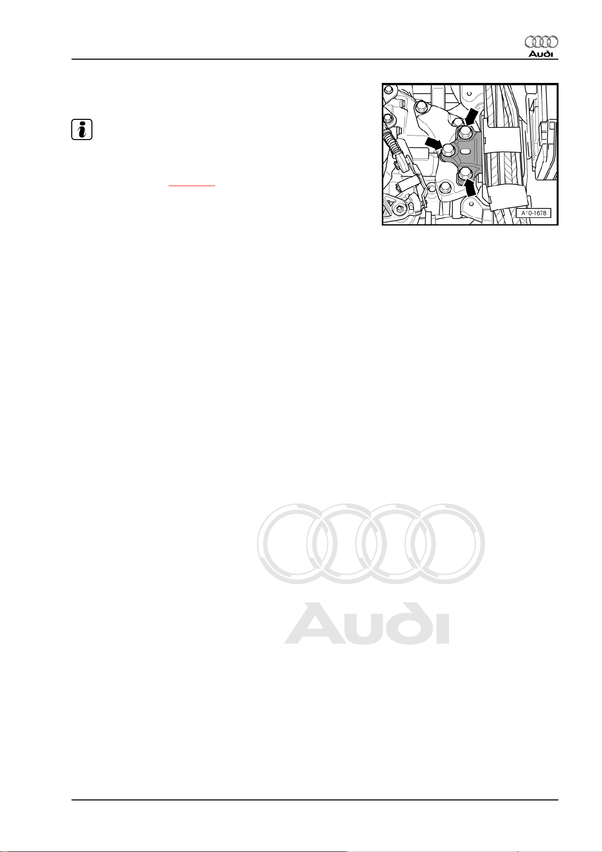
Proceed as follows:
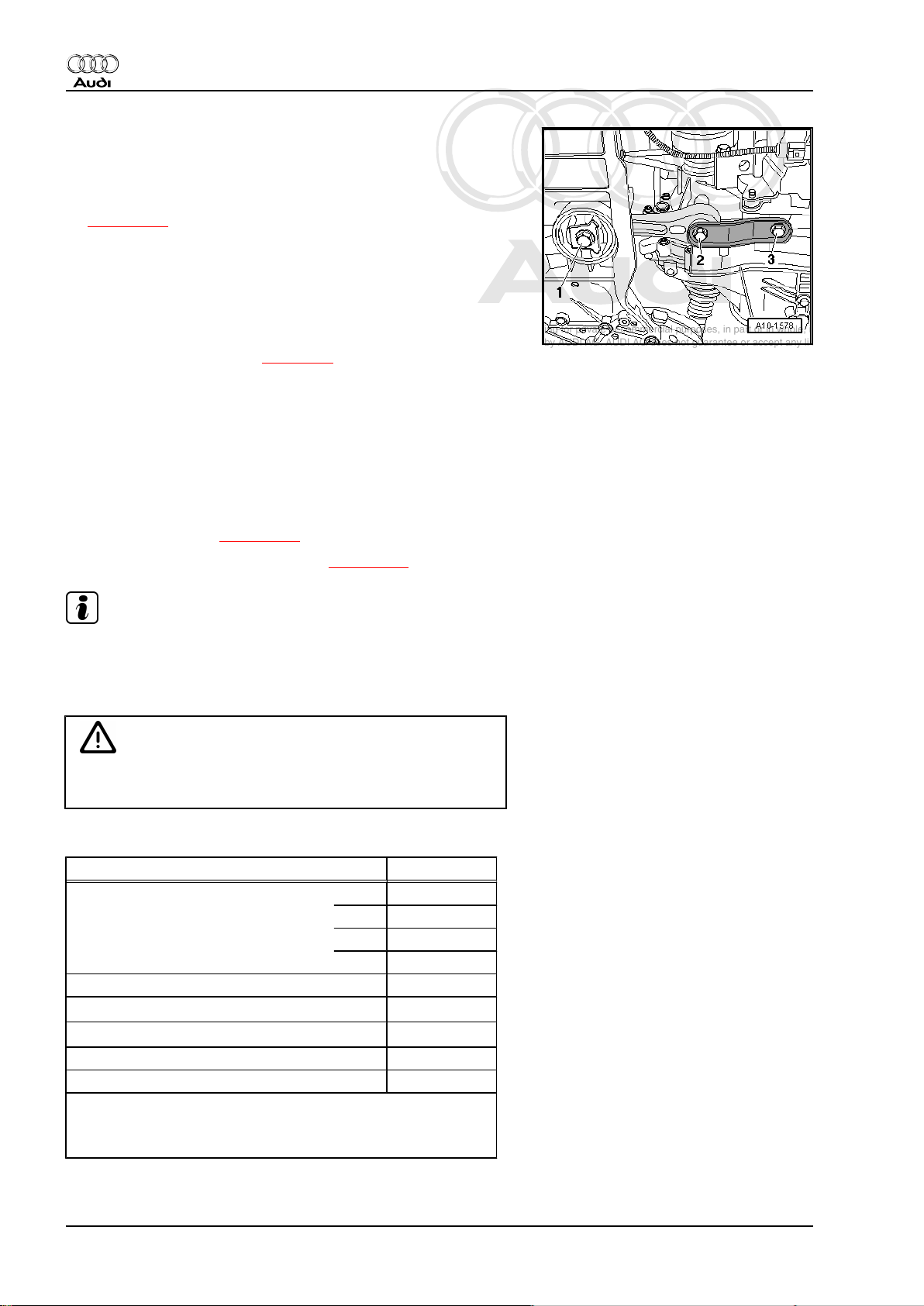
– Check distances at mounting (right-side) for engine and gear‐
box:
• The two bolt heads -2- must be parallel with edge of support
arm -3- for engine mounting.
• There must be a distance of -x- = 16 mm between engine
mounting -1- and engine support -4-.
Note
Distance -x- = 16 mm can also be checked with a metal rod of
suitable size, or similar.
– If the distance measured is too large or small, the assembly
mountings must be adjusted ⇒ page 27 .
2.3 Adjusting assembly mountings
Special tools and workshop
equipment required
♦ Support bracket -10 - 222
A-
♦ 2x spindle -10 - 222 A /11-
♦ Adapter -10 - 222 A /20-
(2x)
♦ Hooks -10 - 222 A /2-
♦ Engine support bracket
(basic set) -T40091-
♦ Engine support bracket
(supplementary set) T40093- with -T40093/3-2and -T40093/3-3-
Audi TT 2007 ➤
Proceed as follows:
• Tightening torques ⇒ page 25 .
2. Assembly mountings 27
Page 34

Protected by copyright. Copying for private or commercial purposes, in part or in whole, is not
permitted unless authorised by AUDI AG. AUDI AG does not guarantee or accept any liability
with respect to the correctness of information in this document. Copyright by AUDI AG.
Audi TT 2007 ➤
4-cylinder direct petrol injection engine (2.0 ltr. 4-valve turbo), mechanics - Edition 11.2006
– Unplug electrical connector at air mass meter -G70- -3-.
– Open clamps -1 and 2- and disconnect air intake hose from
air mass meter.
– Detach air intake connection at lock carrier -4-.
– Pull off engine cover panel.
– Pull activated charcoal filter with hoses attached upwards out
of the retainer -arrow- and place to side.
– Remove bracket for activated charcoal filter.
– Disconnect coolant pipe -arrows-.
– Detach gear selector cable -arrow-.
28 Rep. Gr.10 - Removing and installing engine
Page 35

Protected by copyright. Copying for private or commercial purposes, in part or in whole, is not
permitted unless authorised by AUDI AG. AUDI AG does not guarantee or accept any liability
with respect to the correctness of information in this document. Copyright by AUDI AG.
4-cylinder direct petrol injection engine (2.0 ltr. 4-valve turbo), mechanics - Edition 11.2006
– Position support bracket -10 - 222 A- on bolted flanges of wing
panels using the following tools:
♦ 2x Rack -10 - 222 A /1-
♦ Support bracket -10 - 222 A-
♦ Spindle -10 - 222 A /11- (spindle faces front)
♦ Hooks -10 - 222 A /2-
♦ Adapter -10 - 222 A /20-
♦ Connecting piece -T40091/3- (2x)
– Attach spindle -10 - 222 A /11- with hook -10 - 222 A /2- and
adapter -10 - 222 A /20- to gearbox lifting eye.
– Tighten spindle slightly to take up weight of engine/gearbox
assembly.
– Fit adapter -T40092/3-2- (left-side) and -T40093/3-3- (right-
side) to supports -T40093/3- .
– Unbolt earth wire from longitudinal member (left-side).
– Remove connecting bolt for front section of longitudinal mem‐
ber on left and right.
– Secure adapter -T40092/3-2- (left-side) and -T40093/3-3-
(right-side) to longitudinal members using the removed bolts
-arrow-.
Note
Audi TT 2007 ➤
The illustration shows the left side of the vehicle.
– Fit square-section pipes -T40091/1- with connecting pieces -
T40093/4- into connecting pieces -T40091/3- and supports T40093/3-- as shown in illustration.
2. Assembly mountings 29
Page 36

Protected by copyright. Copying for private or commercial purposes, in part or in whole, is not
permitted unless authorised by AUDI AG. AUDI AG does not guarantee or accept any liability
with respect to the correctness of information in this document. Copyright by AUDI AG.
Audi TT 2007 ➤
4-cylinder direct petrol injection engine (2.0 ltr. 4-valve turbo), mechanics - Edition 11.2006
– Push support -T40091/2- with sliding support -T40093/5- into
the two connecting pieces -T40093/4- .
WARNING
Accident risk from loose components of support bracket.
♦ Secure support -T10091/2- with pins and split pins of con‐
necting pieces -T40093/4- .
♦ Secure connecting pieces and supports with clamping
bolts.
– Fit spindle -10 - 222 A /11- with adapter -10 - 222 A /20- onto
sliding support and onto engine lifting eye.
– Take up weight of engine/gearbox assembly by evenly tight‐
ening two spindles.
– Unscrew bolts -arrows- on engine assembly mounting one af‐
ter the other, renew them (if not already renewed when engine
was installed) and screw in loosely.
– Unscrew bolts -arrows- on gearbox assembly mounting one
after the other, renew them (if not already renewed when en‐
gine was installed) and screw in loosely.
– Slacken bolts on left and right-hand support arms by about two
turns each.
30 Rep. Gr.10 - Removing and installing engine
Page 37

Protected by copyright. Copying for private or commercial purposes, in part or in whole, is not
permitted unless authorised by AUDI AG. AUDI AG does not guarantee or accept any liability
with respect to the correctness of information in this document. Copyright by AUDI AG.
4-cylinder direct petrol injection engine (2.0 ltr. 4-valve turbo), mechanics - Edition 11.2006
– Using a tyre iron, adjust engine/gearbox assembly between
engine mounting -1- and engine support -4- until the specifi‐
cations listed below are obtained:
• The two bolt heads -2- must be parallel with the edge of the
support arm -3-.
• There must be a distance of -x- = 16 mm between engine
mounting -1- and engine support -4-.
Note
Distance -x- = 16 mm can also be checked with a metal rod of
suitable size, or similar.
– Tighten bolts of assembly mounting at gearbox.
– Ensure that the edges of the support arm (on the gearbox as‐
sembly mounting) -1- and gearbox mounting -2- are parallel.
• Dimension -x- must be identical on both sides of mounting.
– Tighten bolts for assembly mounting.
Remaining installation steps are carried out in reverse sequence;
note the following:
– Tighten bolts for front section of longitudinal member ⇒ Rep.
Gr. 50 .
Audi TT 2007 ➤
2. Assembly mountings 31
Page 38

Protected by copyright. Copying for private or commercial purposes, in part or in whole, is not
permitted unless authorised by AUDI AG. AUDI AG does not guarantee or accept any liability
with respect to the correctness of information in this document. Copyright by AUDI AG.
Audi TT 2007 ➤
4-cylinder direct petrol injection engine (2.0 ltr. 4-valve turbo), mechanics - Edition 11.2006
13 – Crankshaft group
1 Cylinder block (pulley end)
1.1 Poly V-belt, bracket for ancillaries - ex‐
ploded view
Note
Before removing, mark direction of rotation of poly V-belt with
chalk or felt-tipped pen. If the belt runs in the opposite direction
when it is refitted, this can cause breakage. Ensure that the belt
is properly seated in the pulleys when installing.
1 - Vibration damper
❑ For poly V-belt
❑ Removing and installing
⇒ page 38
2 - Bolt
❑ 10 Nm + 90°
Renew ⇒ Parts catalogue
3 - Bolt
❑ 23 Nm
4 - Tensioner for poly V-belt
❑ Pivot with open-end
spanner to slacken poly
V-belt
❑ Secure tensioner in po‐
sition using locking pin T10060A-
5 - Bracket for ancillaries
❑ Removing and installing
⇒ page 35
❑ Tightening sequence
⇒ page 33
6 - Bolt
❑ 23 Nm
7 - Nut
❑ 23 Nm
8 - Alternator
❑ Removing and installing
⇒ Electrical system; Re‐
pair group 27
❑ To facilitate attachment
of alternator, knock
back threaded bushes for alternator securing bolts slightly
9 - Bolt
❑ Apply locking fluid when fitting
❑ Locking fluid ⇒ Parts catalogue
32 Rep. Gr.13 - Crankshaft group
Page 39

Protected by copyright. Copying for private or commercial purposes, in part or in whole, is not
permitted unless authorised by AUDI AG. AUDI AG does not guarantee or accept any liability
with respect to the correctness of information in this document. Copyright by AUDI AG.
4-cylinder direct petrol injection engine (2.0 ltr. 4-valve turbo), mechanics - Edition 11.2006
❑ Tightening sequence ⇒ page 33
10 - Bush
❑ 2 x
11 - Bolt
❑ 25 Nm
12 - Air conditioner compressor
❑ Removing and installing ⇒ Air conditioning; Repair group 87
13 - Poly V-belt
❑ Routing of poly V-belt ⇒ page 33
❑ Check for wear
❑ Do not kink
❑ Removing and installing ⇒ page 33
Routing of poly V-belt
Audi TT 2007 ➤
Tightening sequence on bracket for ancillaries
– Proceed as follows:
1. Screw in bolts -1 ... 6- hand-tight.
2. Tighten bolts -1 ... 6- to 45 Nm.
1.2 Removing and installing poly V-belt
Special tools and workshop equipment required
1. Cylinder block (pulley end) 33
Page 40

Protected by copyright. Copying for private or commercial purposes, in part or in whole, is not
permitted unless authorised by AUDI AG. AUDI AG does not guarantee or accept any liability
with respect to the correctness of information in this document. Copyright by AUDI AG.
Audi TT 2007 ➤
4-cylinder direct petrol injection engine (2.0 ltr. 4-valve turbo), mechanics - Edition 11.2006
♦ Locking pin -T10060A-
Removing
– Unplug electrical connector at air mass meter -G70- -3-.
– Open clamps -1 and 2- and disconnect air intake hose from
air mass meter.
– Detach air intake connection at lock carrier -4-.
– Pull off engine cover panel.
– Lift out activated charcoal filter from retainer with pipes con‐
nected -arrow- and lay aside.
Note
Before removing, mark direction of rotation of poly V-belt with
chalk or felt-tipped pen. If the belt runs in the opposite direction
when it is refitted, this can cause breakage.
– Mark direction of rotation of poly V-belt.
– To slacken poly V-belt, turn tensioner in -direction of arrow-.
34 Rep. Gr.13 - Crankshaft group
Page 41

Protected by copyright. Copying for private or commercial purposes, in part or in whole, is not
permitted unless authorised by AUDI AG. AUDI AG does not guarantee or accept any liability
with respect to the correctness of information in this document. Copyright by AUDI AG.
4-cylinder direct petrol injection engine (2.0 ltr. 4-valve turbo), mechanics - Edition 11.2006
– Lock tensioner in position with locking pin -T10060A- .
– Remove poly V-belt.
Installing
Installation is carried out in the reverse order; note the following:
Note
Before fitting poly V-belt, make sure all ancillary units (alternator
and air-conditioner compressor) are firmly secured.
– Fit the poly V-belt onto the crankshaft and air conditioner com‐
pressor pulleys.
– Then position poly V-belt on alternator pulley and release ten‐
sioner.
– Check that poly V-belt is properly seated.
– Start engine and check that belt runs properly.
Audi TT 2007 ➤
1.3 Removing and installing bracket for an‐
cillaries
Special tools and workshop equipment required
♦ Locking pin -T10060A-
1. Cylinder block (pulley end) 35
Page 42

Protected by copyright. Copying for private or commercial purposes, in part or in whole, is not
permitted unless authorised by AUDI AG. AUDI AG does not guarantee or accept any liability
with respect to the correctness of information in this document. Copyright by AUDI AG.
Audi TT 2007 ➤
4-cylinder direct petrol injection engine (2.0 ltr. 4-valve turbo), mechanics - Edition 11.2006
Removing
– Unplug electrical connector at air mass meter -G70- -3-.
– Open clamps -1 and 2- and disconnect air intake hose from
air mass meter.
– Detach air intake connection at lock carrier -4-.
– Pull off engine cover panel.
– Lift out activated charcoal filter from retainer with pipes con‐
nected -arrow- and lay aside.
Note
Before removing, mark direction of rotation of poly V-belt with
chalk or felt-tipped pen. If the belt runs in the opposite direction
when it is refitted, this can cause breakage.
– To slacken poly V-belt, turn tensioner in -direction of arrow-.
– Lock tensioner in position with locking pin -T10060A- .
– Take off poly V-belt.
36 Rep. Gr.13 - Crankshaft group
Page 43

Protected by copyright. Copying for private or commercial purposes, in part or in whole, is not
permitted unless authorised by AUDI AG. AUDI AG does not guarantee or accept any liability
with respect to the correctness of information in this document. Copyright by AUDI AG.
4-cylinder direct petrol injection engine (2.0 ltr. 4-valve turbo), mechanics - Edition 11.2006
– Remove tensioner for poly V-belt -arrows-.
– Discharge the refrigerant system ⇒ Rep. Gr. 87 ; Air condi‐
tioner system with refrigerant R134a .
– Remove alternator ⇒ Electrical system; Repair group 27 .
– Remove centre noise insulation -fasteners 1 ... 4-.
Audi TT 2007 ➤
– Remove right noise insulation -arrows-.
– Remove noise insulation frame -arrow-.
– Remove air conditioner compressor ⇒ Rep. Gr. 87 ; Heating,
air conditioning system .
1. Cylinder block (pulley end) 37
Page 44

Protected by copyright. Copying for private or commercial purposes, in part or in whole, is not
permitted unless authorised by AUDI AG. AUDI AG does not guarantee or accept any liability
with respect to the correctness of information in this document. Copyright by AUDI AG.
Audi TT 2007 ➤
4-cylinder direct petrol injection engine (2.0 ltr. 4-valve turbo), mechanics - Edition 11.2006
– Detach bracket for ancillaries: bolts -1 … 6-.
Installing
Installation is carried out in the reverse order; note the following:
• Tightening torques ⇒ page 32
– Tighten bolts in the sequence -1 ... 6-.
– Install alternator ⇒ Electrical system; Repair group 27 .
– Install air conditioner compressor ⇒ Rep. Gr. 87 ; Heating, air
conditioning system .
– Install poly V-belt ⇒ page 33 .
– Connect battery. Procedures required ⇒ Electrical system;
Repair group 27 .
1.4 Removing and installing vibration damp‐
er
Removing
• Poly V-belt must be removed ⇒ page 33 .
– Remove centre noise insulation -fasteners 1 ... 4-.
38 Rep. Gr.13 - Crankshaft group
Page 45

Protected by copyright. Copying for private or commercial purposes, in part or in whole, is not
permitted unless authorised by AUDI AG. AUDI AG does not guarantee or accept any liability
with respect to the correctness of information in this document. Copyright by AUDI AG.
4-cylinder direct petrol injection engine (2.0 ltr. 4-valve turbo), mechanics - Edition 11.2006
– Remove right noise insulation -arrows-.
– Remove noise insulation frame -arrow-.
Audi TT 2007 ➤
– Unscrew vibration damper and remove.
Note
To loosen and tighten the vibration damper, counterhold with ring
spanner on centre bolt.
Installing
Installation is carried out in the reverse order; note the following:
• Tightening torques ⇒ page 32
– When installing the vibration damper, use only genuine bolts
(same as original equipment): ⇒ Parts catalogue .
♦ The vibration damper can only be installed in one position. The
hole -arrow- in the crankshaft vibration damper must be loca‐
ted over the projection on the toothed belt sprocket.
1. Cylinder block (pulley end) 39
Page 46

Protected by copyright. Copying for private or commercial purposes, in part or in whole, is not
permitted unless authorised by AUDI AG. AUDI AG does not guarantee or accept any liability
with respect to the correctness of information in this document. Copyright by AUDI AG.
Audi TT 2007 ➤
4-cylinder direct petrol injection engine (2.0 ltr. 4-valve turbo), mechanics - Edition 11.2006
1.5 Front sealing flange - exploded view
1 - Bolt
❑
90 Nm + 90° (1/4 turn)
further
❑ Renew
❑ Do not lubricate with oil
❑ Attaching counterhold
tool 3415
2 - Crankshaft sprocket
❑ Contact surface be‐
tween sprocket and
crankshaft must be free
of oil
❑ Can only be installed in
one position
3 - Bolt
❑ Tightening sequence
⇒ page 40
4 - Oil seal
❑ Renewing ⇒ page 41
❑ Do not lubricate with oil
5 - Sealing flange (front)
❑ Must be positioned on
dowel pins
❑ Removing and installing
⇒ page 44
6 - Dowel pins
7 - Diamond-coated washer for
toothed belt sprocket
❑ Renew washer if tooth‐
ed belt sprocket is re‐
moved
8 - Bolt
❑ Tightening sequence ⇒ page 40
9 - Cylinder block
❑ Removing and installing crankshaft ⇒ page 53
❑ Dismantling and assembling pistons and conrods ⇒ page 60
⇒ page 65
Tightening sequence for front sealing flange
– Proceed as follows:
1. Screw in bolts -1 ... 10- hand-tight.
2. Tighten bolts -1 ... 6- in diagonal sequence and in stages to
15 Nm.
3. Tighten bolts -7 ... 10- to 15 Nm.
40 Rep. Gr.13 - Crankshaft group
Page 47

Protected by copyright. Copying for private or commercial purposes, in part or in whole, is not
permitted unless authorised by AUDI AG. AUDI AG does not guarantee or accept any liability
with respect to the correctness of information in this document. Copyright by AUDI AG.
4-cylinder direct petrol injection engine (2.0 ltr. 4-valve turbo), mechanics - Edition 11.2006
1.6 Renewing crankshaft oil seal - pulley end
Special tools and workshop
equipment required
♦ Oil seal extractor -3203-
♦ Counterhold tool -3415-
♦ Assembly tool -T10053-
♦ Torque wrench -V.A.G
1331-
♦ Torque wrench -V.A.G
1332-
Audi TT 2007 ➤
Removing
– Remove poly V-belt ⇒ page 33 .
– Remove toothed belt ⇒ page 63 .
– Remove crankshaft toothed belt sprocket. To do this, counter-
hold sprocket with special tool -3415- .
1. Cylinder block (pulley end) 41
Page 48

Protected by copyright. Copying for private or commercial purposes, in part or in whole, is not
permitted unless authorised by AUDI AG. AUDI AG does not guarantee or accept any liability
with respect to the correctness of information in this document. Copyright by AUDI AG.
Audi TT 2007 ➤
4-cylinder direct petrol injection engine (2.0 ltr. 4-valve turbo), mechanics - Edition 11.2006
– Unscrew central bolt -1- for crankshaft toothed belt sprocket
-2- and remove sprocket.
– Remove diamond-coated washer -3- from toothed belt sprock‐
et.
– To guide oil seal extractor, screw central bolt into crankshaft
onto stop by hand.
– Unscrew inner part of oil seal extractor -3203- nine turns (ap‐
prox. 20 mm) from the outer part and lock in position with the
knurled screw.
– Lubricate threaded head of oil seal extractor -3203- , place it
in position and, while exerting firm pressure, screw it into oil
seal as far as possible.
– Loosen knurled screw and turn inner part against crankshaft
until oil seal is pulled out.
– Clamp flats of oil seal extractor in vice. Remove oil seal with
pliers.
Installing
• Tightening torques ⇒ page 40
– Clean contact surface and sealing surface.
– Remove oil residue from crankshaft journal with a clean cloth.
– Position guide sleeve T10053/1 from assembly tool -T10053-
on crankshaft journal.
– Push oil seal over guide sleeve onto crankshaft journal.
– Press in oil seal with central bolt of toothed belt sprocket and
thrust sleeve of assembly tool -T10053- until flush.
42 Rep. Gr.13 - Crankshaft group
Page 49

Protected by copyright. Copying for private or commercial purposes, in part or in whole, is not
permitted unless authorised by AUDI AG. AUDI AG does not guarantee or accept any liability
with respect to the correctness of information in this document. Copyright by AUDI AG.
4-cylinder direct petrol injection engine (2.0 ltr. 4-valve turbo), mechanics - Edition 11.2006
– Install crankshaft toothed belt sprocket -2- with new diamond-
coated washer -3- and new central bolt -1-.
Note
♦
Contact surfaces between toothed belt sprocket, diamondcoated washer and crankshaft must be free of oil.
♦
Do not lubricate bolt for crankshaft sprocket.
– Use counterhold tool -3415- to tighten crankshaft toothed belt
sprocket.
Fit toothed belt (adjust valve timing) ⇒ page 66
– Install poly V-belt ⇒ page 33 .
Audi TT 2007 ➤
1. Cylinder block (pulley end) 43
Page 50

Protected by copyright. Copying for private or commercial purposes, in part or in whole, is not
permitted unless authorised by AUDI AG. AUDI AG does not guarantee or accept any liability
with respect to the correctness of information in this document. Copyright by AUDI AG.
Audi TT 2007 ➤
4-cylinder direct petrol injection engine (2.0 ltr. 4-valve turbo), mechanics - Edition 11.2006
1.7 Removing and installing sealing flange (front)
Special tools and workshop
equipment required
♦ Counterhold tool -3415-
♦ Assembly tool -T10053-
♦ Torque wrench -V.A.G
1331-
♦ Torque wrench -V.A.G
1332-
♦ Electric drill with plastic
brush attachment
♦ Safety goggles
♦ Sealant ⇒ Parts catalogue
Removing
– Remove poly V-belt ⇒ page 33 .
– Remove toothed belt ⇒ page 63 .
– Remove crankshaft toothed belt sprocket. To do this, counter-
hold sprocket with special tool -3415- .
44 Rep. Gr.13 - Crankshaft group
Page 51

Protected by copyright. Copying for private or commercial purposes, in part or in whole, is not
permitted unless authorised by AUDI AG. AUDI AG does not guarantee or accept any liability
with respect to the correctness of information in this document. Copyright by AUDI AG.
4-cylinder direct petrol injection engine (2.0 ltr. 4-valve turbo), mechanics - Edition 11.2006
– Unscrew central bolt -1- for crankshaft toothed belt sprocket
-2- and remove sprocket.
– Remove diamond-coated washer -3- from toothed belt sprock‐
et.
– Remove bolts -1 ... 10-.
– Lever off front sealing flange and remove.
– Drive out oil seal with flange removed.
Installing
• Tightening torque ⇒ page 40
Audi TT 2007 ➤
Note
Place a cloth over the exposed section of the sump.
– Carefully remove any sealant residue on the cylinder block
and sump.
WARNING
Wear safety goggles.
– Remove sealant residue from sealing flange with rotating plas‐
tic brush or similar.
– Clean sealing surfaces; they must be free of oil and grease.
– Cut off tube nozzle at front marking (nozzle approx. 2 mm ∅).
1. Cylinder block (pulley end) 45
Page 52

Protected by copyright. Copying for private or commercial purposes, in part or in whole, is not
permitted unless authorised by AUDI AG. AUDI AG does not guarantee or accept any liability
with respect to the correctness of information in this document. Copyright by AUDI AG.
Audi TT 2007 ➤
4-cylinder direct petrol injection engine (2.0 ltr. 4-valve turbo), mechanics - Edition 11.2006
– Apply a thin bead of sealant at the edge of the joint between
the cylinder block and the sump -arrows-.
– Apply the bead of sealant onto the clean sealing surface of the
sealing flange as illustrated -arrow-.
• Thickness of sealant bead: 2 ... 3 mm
Caution
Make sure oil strainer is not clogged by excess sealant.
♦ The bead of sealant must not be thicker than specified.
Note
Sealant bead must not be wider than 3 mm, otherwise excess
sealant could ingress into sump and clog strainer in oil intake pipe.
– Coat the lower sealing surface on the sealing flange lightly with
sealant -hatched area-.
Note
The sealing flange must be installed within 5 minutes after apply‐
ing sealant.
– Push the sealing flange carefully onto the dowel sleeves on
the cylinder block.
Note
Use guide sleeve -T10053/1- to attach sealing flange with oil seal
fitted.
– Tighten sealing flange bolts in three stages as follows:
1. Screw in bolts -1 ... 10- hand-tight.
2. Tighten bolts -1 ... 6- in diagonal sequence and in stages.
3. Tighten bolts -7 ... 10-.
– Install crankshaft oil seal (pulley end) ⇒ page 42 .
46 Rep. Gr.13 - Crankshaft group
Page 53

Protected by copyright. Copying for private or commercial purposes, in part or in whole, is not
permitted unless authorised by AUDI AG. AUDI AG does not guarantee or accept any liability
with respect to the correctness of information in this document. Copyright by AUDI AG.
4-cylinder direct petrol injection engine (2.0 ltr. 4-valve turbo), mechanics - Edition 11.2006
– Install crankshaft toothed belt sprocket -2- with new diamond-
coated washer -3- and new central bolt -1-.
Note
♦
Contact surfaces between toothed belt sprocket, diamondcoated washer and crankshaft must be free of oil.
♦
Do not lubricate bolt for crankshaft sprocket.
– Use counterhold tool -3415- to tighten crankshaft toothed belt
sprocket.
Remaining installation steps are carried out in reverse sequence;
note the following:
Installing toothed belt and adjusting valve timing ⇒ page 66 .
– Install vibration damper ⇒ page 38 .
– Install poly V-belt ⇒ page 33 .
Audi TT 2007 ➤
1. Cylinder block (pulley end) 47
Page 54

Protected by copyright. Copying for private or commercial purposes, in part or in whole, is not
permitted unless authorised by AUDI AG. AUDI AG does not guarantee or accept any liability
with respect to the correctness of information in this document. Copyright by AUDI AG.
Audi TT 2007 ➤
4-cylinder direct petrol injection engine (2.0 ltr. 4-valve turbo), mechanics - Edition 11.2006
2 Cylinder block (gearbox end)
2.1 Rear sealing flange and dual-mass flywheel - exploded view
Note
Servicing clutch:⇒ Rep. Gr. 30
1 - Bolt
❑ For dual-mass flywheel/
drive plate
❑ 60 + 90° (60 Nm + 90°
(1/4 turn) further
❑ Renew
2 - Dual-mass flywheel
❑ Removing and installing
dual-mass flywheel
⇒ page 49
❑ Can only be installed in
one position. Holes are
off-set
3 - Intermediate plate
❑ Must be positioned on
dowel sleeves
❑ Do not damage/bend
when assembling
❑ Is fitted on sealing
flange ⇒ page 49
4 - Bolt
❑ Tightening sequence
⇒ page 49
5 - Sealing flange with oil seal
(rear)
❑ Renew only as com‐
plete unit
❑ Use guide sleeve provi‐
ded when fitting
❑ Removing and installing
⇒ page 50
❑ Do not lubricate/grease
sealing lip of oil seal
❑ Before installing, remove oil residue from crankshaft journal with a clean cloth.
❑ Guide sleeve is not to be removed until sealing flange has been slipped onto crankshaft journal
6 - Dowel pin
7 - Cylinder block
❑ Removing and installing crankshaft ⇒ page 53
❑ Dismantling and assembling pistons and conrods ⇒ page 60
8 - Bolt
❑ Tightening sequence ⇒ page 49
48 Rep. Gr.13 - Crankshaft group
Page 55

Protected by copyright. Copying for private or commercial purposes, in part or in whole, is not
permitted unless authorised by AUDI AG. AUDI AG does not guarantee or accept any liability
with respect to the correctness of information in this document. Copyright by AUDI AG.
4-cylinder direct petrol injection engine (2.0 ltr. 4-valve turbo), mechanics - Edition 11.2006
Tightening sequence (gearbox end)
– Proceed as follows:
1. Screw in bolts -1 ... 8- hand-tight.
2. Tighten bolts -1 ... 6- in diagonal sequence and in stages to
15 Nm.
3. Tighten bolts -7 ... 8- to 15 Nm.
Installing intermediate plate
– Fit intermediate plate on sealing flange and push onto dowel
sleeves -arrows-.
Audi TT 2007 ➤
2.2 Removing and installing dual-mass fly‐
wheel
Special tools and workshop equipment required
♦ Counterhold tool -3067-
Removing
Caution
To prevent damage to the dual-mass flywheel when removing,
the bolts -B- must not be removed with an impact wrench or
similar. The bolts may only be removed by hand using con‐
ventional tools.
– Mark position of dual-mass flywheel in relation to engine.
2. Cylinder block (gearbox end) 49
Page 56

Protected by copyright. Copying for private or commercial purposes, in part or in whole, is not
permitted unless authorised by AUDI AG. AUDI AG does not guarantee or accept any liability
with respect to the correctness of information in this document. Copyright by AUDI AG.
Audi TT 2007 ➤
4-cylinder direct petrol injection engine (2.0 ltr. 4-valve turbo), mechanics - Edition 11.2006
– Rotate the dual-mass flywheel -A- so that the bolts -B- align
centrally with the holes -arrows-.
– When unscrewing bolts -B-, ensure that none of the bolt heads
come into contact with the dual-mass flywheel -arrows-. The
flywheel will otherwise be damaged as the bolts are screwed
out further.
– Insert counterhold -3067- in hole on cylinder block -B-.
– Unbolt dual-mass flywheel.
Installing
Installation is carried out in the reverse order; note the following:
• Tightening torque ⇒ page 48
– Use new securing bolts.
– Insert counterhold -3067- in hole on cylinder block -A-.
2.3 Removing and installing sealing flange (rear)
Special tools and workshop equipment required
♦ Electric drill with plastic brush attachment
♦ Safety goggles
50 Rep. Gr.13 - Crankshaft group
Page 57

Protected by copyright. Copying for private or commercial purposes, in part or in whole, is not
permitted unless authorised by AUDI AG. AUDI AG does not guarantee or accept any liability
with respect to the correctness of information in this document. Copyright by AUDI AG.
4-cylinder direct petrol injection engine (2.0 ltr. 4-valve turbo), mechanics - Edition 11.2006
♦ Sealant ⇒ Parts catalogue
Removing
• Gearbox removed.
– Remove dual-mass flywheel ⇒ page 49 .
– Detach intermediate plate at sealing flange and dowel sleeves
-arrows-.
– Remove bolts -1 ... 8-.
– Pull off sealing flange (rear).
Installing
Audi TT 2007 ➤
• Tightening torques ⇒ page 48
Note
Place a cloth over the exposed section of the sump.
– Carefully remove any sealant residue on the cylinder block
and sump.
– Clean sealing surfaces; they must be free of oil and grease.
– Cut off tube nozzle at front marking (nozzle approx. 2 mm ∅).
– Apply a thin bead of sealant at the edge of the joint between
the cylinder block and the sump -arrows-.
2. Cylinder block (gearbox end) 51
Page 58

Protected by copyright. Copying for private or commercial purposes, in part or in whole, is not
permitted unless authorised by AUDI AG. AUDI AG does not guarantee or accept any liability
with respect to the correctness of information in this document. Copyright by AUDI AG.
Audi TT 2007 ➤
4-cylinder direct petrol injection engine (2.0 ltr. 4-valve turbo), mechanics - Edition 11.2006
– Coat the lower sealing surface on the sealing flange lightly with
sealant -hatched area-.
Caution
Make sure oil strainer is not clogged by excess sealant.
♦ The bead of sealant must not be thicker than specified.
Note
The sealing flange must be installed within 5 minutes after apply‐
ing sealant.
– Carefully push sealing flange -2- together with guide sleeve
-1- (fitted on replacement part) onto crankshaft when instal‐
ling.
– Push the sealing flange carefully onto the dowel sleeves on
the cylinder block.
– Tighten bolts in the specified sequence:
1. Screw in bolts -1 ... 8- hand-tight.
2. Tighten bolts -1 ... 6- in diagonal sequence and in stages.
3. Tighten bolts -7 ... 8-.
Remaining installation steps are carried out in reverse sequence;
note the following:
– Fit intermediate plate on sealing flange and push onto dowel
sleeves -arrows-.
– Install dual-mass flywheel ⇒ page 49 .
52 Rep. Gr.13 - Crankshaft group
Page 59

Protected by copyright. Copying for private or commercial purposes, in part or in whole, is not
permitted unless authorised by AUDI AG. AUDI AG does not guarantee or accept any liability
with respect to the correctness of information in this document. Copyright by AUDI AG.
Audi TT 2007 ➤
4-cylinder direct petrol injection engine (2.0 ltr. 4-valve turbo), mechanics - Edition 11.2006
3 Crankshaft
3.1 Crankshaft - exploded view
Note
Secure engine to repair stand using engine and gearbox support
-VAS 6095- when dismantling/assembling engine ⇒ page 20 .
1 - Bolt
❑
65 Nm + 1/4 turn (90 °)
further
❑ Renew
2 - Bearing cap
❑ Bearing cap 1: Pulley
end
❑ Bearing shell retaining
lugs (cylinder block/
bearing cap) must be on
the same side
3 - Bolt
❑
10 Nm + 1/4 turn (90 °)
further
❑ Renew
❑ Sender wheel must be
renewed if bolts are
loosened ⇒ page 54
4 - Needle bearing
❑ For vehicles with man‐
ual gearbox
❑ Extracting and driving in
⇒ page 57
5 - Sender wheel
❑ For engine speed send‐
er -G28-
❑ Can only be installed in
one position. Holes are
off-set
❑ Sender wheel must be
renewed if bolts are
loosened
❑ Removing and installing
⇒ page 54
6 - Crankshaft
❑ After removing, place it down so that the sender wheel -item 5- is not damaged and the crankshaft does
not rest on the sender wheel
❑ Axial clearance ⇒ page 55
❑ Radial clearance ⇒ page 56
❑ Do not rotate the crankshaft when checking the radial clearance
❑ Crankshaft dimensions ⇒ page 55
3. Crankshaft 53
Page 60

Protected by copyright. Copying for private or commercial purposes, in part or in whole, is not
permitted unless authorised by AUDI AG. AUDI AG does not guarantee or accept any liability
with respect to the correctness of information in this document. Copyright by AUDI AG.
Audi TT 2007 ➤
4-cylinder direct petrol injection engine (2.0 ltr. 4-valve turbo), mechanics - Edition 11.2006
7 - Thrust washers
❑ For bearing No. 3
8 - Bearing shell for cylinder block
❑ With oil groove
❑ Do not interchange used bearing shells (mark positions)
❑ Classification for replacement parts ⇒ page 57
9 - Chain sprocket
❑ For oil pump chain
❑ Renewing ⇒ page 58
10 - Bearing shell
❑ Without oil groove
❑ Do not interchange used bearing shells (mark positions)
❑ The crankshaft bearing shells in the bearing caps are only supplied as spare parts with “yellow” colour-
coding.
Removing and installing sender wheel
– Sender wheel -2- must always be renewed after slackening off
bolts -1-.
Note
♦
If the countersunk bolts are tightened a second time, the seats
for the bolt heads in the sender wheel will be deformed to such
an extent that the bolt heads make contact with the crankshaft
-3- -arrows- and the sender wheel beneath the bolts will be
loose.
♦
Sender wheel can only be fitted in one position because holes
are offset.
• Tightening torque ⇒ page 53
54 Rep. Gr.13 - Crankshaft group
Page 61

Protected by copyright. Copying for private or commercial purposes, in part or in whole, is not
permitted unless authorised by AUDI AG. AUDI AG does not guarantee or accept any liability
with respect to the correctness of information in this document. Copyright by AUDI AG.
4-cylinder direct petrol injection engine (2.0 ltr. 4-valve turbo), mechanics - Edition 11.2006
Identification of top crankshaft bearings
Note
Arrow points in direction of travel.
Top bearing shells of the correct thickness are allocated to the
cylinder block at the factory. Coloured dots are used to identify
the thickness of the bearing shells.
Letter codes on the lower sealing surface of the cylinder block
indicate the thickness of the bearing shell to be fitted at each lo‐
cation.
G = Yellow
B = Blue
W = White
Note
♦
Use blue bearing shells if the identification is no longer visible.
♦
The bottom crankshaft bearing shells are only supplied as re‐
placement parts with “yellow” marking.
Audi TT 2007 ➤
3.2 Crankshaft dimensions
(in mm)
Honing dimension Crankshaft main
Conrod journal ∅
bearing journal ∅
Basic dimension
1st undersize
2nd undersize
3rd undersize
-0.017
54.00
-0.037
-0.017
53.75
-0.037
-0.017
53.50
-0.037
-0.017
53.25
-0.037
47.80
47.55
47.30
47.05
-0.022
-0.042
-0.022
-0.042
-0.022
-0.042
-0.022
-0.042
3.3 Measuring axial clearance of crankshaft
Special tools and workshop equipment required
3. Crankshaft 55
Page 62

Protected by copyright. Copying for private or commercial purposes, in part or in whole, is not
permitted unless authorised by AUDI AG. AUDI AG does not guarantee or accept any liability
with respect to the correctness of information in this document. Copyright by AUDI AG.
Audi TT 2007 ➤
4-cylinder direct petrol injection engine (2.0 ltr. 4-valve turbo), mechanics - Edition 11.2006
♦ Universal dial gauge bracket -VW 387-
♦ Dial gauge -VAS 6079-
Procedure
– Bolt dial gauge -VAS 6079- with dial gauge bracket -VW 387-
onto cylinder block and set it against crank web.
– Push crankshaft against dial gauge by hand and set gauge to
“0”.
– Push crankshaft away from dial gauge and read off value.
Axial clearance:
• New: 0.07 ... 0.23 mm.
• Wear limit: 0.30 mm.
3.4 Measuring radial clearance of crank‐
shaft
Special tools and workshop equipment required
♦ Plastigage
Procedure
Note
♦
Do not interchange used bearings.
♦
Bearing shells worn down to nickel layer must be renewed.
– Remove main bearing caps and clean bearing caps and jour‐
nals.
– Place Plastigage onto bearing journal or into bearing shells
(length of Plastigage should correspond to width of bearing).
• The Plastigage must be positioned in the centre of the bearing
shell.
56 Rep. Gr.13 - Crankshaft group
Page 63

Protected by copyright. Copying for private or commercial purposes, in part or in whole, is not
permitted unless authorised by AUDI AG. AUDI AG does not guarantee or accept any liability
with respect to the correctness of information in this document. Copyright by AUDI AG.
4-cylinder direct petrol injection engine (2.0 ltr. 4-valve turbo), mechanics - Edition 11.2006
– Fit main bearing caps and tighten to 65 Nm without rotating
crankshaft.
– Remove main bearing caps once more.
– Compare width of Plastigage with measurement scale:
Radial clearance:
• New: 0.017 ... 0.037 mm.
• Wear limit: 0.15 mm.
3.5 Extracting and driving in needle bearing for crankshaft
Special tools and workshop equipment required
♦ Puller -T10055-
Audi TT 2007 ➤
♦ With adapter -T10055/3-
♦ Centring mandrel -3176-
♦ Or drift -VW 207 C-
♦ Puller e.g. Kukko -21/2-
Removing
– Extract with commercially available puller e.g. Kukko -21/2-
-arrow-, adapter -T10055/3- and puller -T10055- .
Installing
Note
The lettering on the needle bearing must be visible when installed.
3. Crankshaft 57
Page 64

Protected by copyright. Copying for private or commercial purposes, in part or in whole, is not
permitted unless authorised by AUDI AG. AUDI AG does not guarantee or accept any liability
with respect to the correctness of information in this document. Copyright by AUDI AG.
Audi TT 2007 ➤
4-cylinder direct petrol injection engine (2.0 ltr. 4-valve turbo), mechanics - Edition 11.2006
– Drive in with drift -VW 207 C- or centring mandrel -3176- .
Installation depth of -a- = 2 mm
3.6 Removing and installing chain sprocket
Special tools and workshop equipment required
♦ Drift sleeve -30 - 100-
♦ Thrust plate -40 - 105-
♦ Two-arm puller, commercially available
♦ Protective gloves
58 Rep. Gr.13 - Crankshaft group
Page 65

Protected by copyright. Copying for private or commercial purposes, in part or in whole, is not
permitted unless authorised by AUDI AG. AUDI AG does not guarantee or accept any liability
with respect to the correctness of information in this document. Copyright by AUDI AG.
4-cylinder direct petrol injection engine (2.0 ltr. 4-valve turbo), mechanics - Edition 11.2006
Removing
– Remove sump with oil pump ⇒ page 120 .
– Remove front sealing flange ⇒ page 44 .
– Pull chain sprocket off crankshaft with puller -2- (Kukko 44-1
or similar). Use special tool 40-105 to protect end of crank‐
shaft.
Installing
Installation is carried out in the reverse order; note the following:
WARNING
Wear protective gloves.
– Heat chain sprocket in oven for approx. 15 minutes to 220°C.
Note
Installation position: wide collar on sprocket facing towards en‐
gine,
Audi TT 2007 ➤
– Fit chain sprocket on end of crankshaft using pliers, and press
onto crankshaft as far as the stop using drift sleeve -30 - 100- .
– Install sump with oil pump ⇒ page 120 .
3. Crankshaft 59
Page 66

Protected by copyright. Copying for private or commercial purposes, in part or in whole, is not
permitted unless authorised by AUDI AG. AUDI AG does not guarantee or accept any liability
with respect to the correctness of information in this document. Copyright by AUDI AG.
Audi TT 2007 ➤
4-cylinder direct petrol injection engine (2.0 ltr. 4-valve turbo), mechanics - Edition 11.2006
4 Pistons and conrods - exploded view
1 - Conrod bolt
❑
30 Nm + 1/4 turn (90°)
further
❑ Renew
❑ Lubricate threads and
contact surface
❑ Use old bolts when
measuring radial clear‐
ance
❑ To measure radial clear‐
ance, tighten to 30 Nm
but do not turn further
2 - Pressure relief valve
27 Nm
❑ Opening pressure:
1.6 ... 1.9 bar
3 - Oil spray jet
❑ For piston cooling
4 - Conrod bearing cap
❑ Note installation posi‐
tion
❑ Due to the cracking
method used to sepa‐
rate the bearing cap
from the conrod in man‐
ufacture, the caps only
fit in one position and
only on the appropriate
conrod.
❑ Mark cylinder number
-B-
❑ Installation position:
Markings -A- face to‐
wards pulley end
5 - Bearing shells
❑ Upper bearing shell with oil hole for piston pin lubrication
❑ Installation position ⇒ page 62
❑ Do not interchange used bearing shells (mark positions)
❑ Axial clearance when new: 0.10...0.35 mm; wear limit: 0.40 mm
❑ Check radial clearance with Plastigage - (new): 0.02 ... 0.06 mm; wear limit: 0.09 mm. Do not turn crank‐
shaft when measuring radial clearance
6 - Conrod
❑ Only renew as a complete set
❑ Mark cylinder number -B❑ Installation position: Markings -A- face towards pulley end
❑ With oil drilling for piston pin lubrication
7 - Circlip
8 - Piston pin
❑ If difficult to move, heat piston to approx. 60 °C
❑ Remove and install using drift -VW 222 A-
60 Rep. Gr.13 - Crankshaft group
Page 67

Protected by copyright. Copying for private or commercial purposes, in part or in whole, is not
permitted unless authorised by AUDI AG. AUDI AG does not guarantee or accept any liability
with respect to the correctness of information in this document. Copyright by AUDI AG.
4-cylinder direct petrol injection engine (2.0 ltr. 4-valve turbo), mechanics - Edition 11.2006
9 - Piston
❑ Checking ⇒ page 61
❑ Mark installation position and cylinder number
❑ Arrow on piston crown points to pulley end
❑ Install using piston ring clamp
❑ Piston and cylinder dimensions ⇒ page 62
❑ Checking cylinder bore ⇒ page 62
10 - Piston rings
❑ Offset gaps by 120 °
❑ Use piston ring pliers to remove and install
❑ “TOP” must face towards piston crown
❑ Checking ring gap ⇒ page 61
❑ Checking ring-to-groove clearance ⇒ page 61
Checking piston ring gap
– Insert ring at right angle to cylinder wall from above and push
down into lower cylinder opening approx. 15 mm from bottom
of cylinder. Use a piston without rings to push ring into bore.
Audi TT 2007 ➤
Piston ring
New Wear limit
Dimensions in mm
Compression ring 0.20...0.40 0.8
Oil scraper ring 0.25...0.50 0.8
Checking ring-to-groove clearance
– Clean groove in piston before checking clearance.
Piston ring
New Wear limit
Dimensions in mm
Compression ring 0.06...0.09 0.20
Oil scraper ring 0.03...0.06 0.15
Checking piston
– Measure approx. 10 mm from the bottom edge, perpendicular
to the piston pin axis.
♦ Deviation from nominal dimension: max. 0.04 mm
4. Pistons and conrods - exploded view 61
Page 68

Protected by copyright. Copying for private or commercial purposes, in part or in whole, is not
permitted unless authorised by AUDI AG. AUDI AG does not guarantee or accept any liability
with respect to the correctness of information in this document. Copyright by AUDI AG.
Audi TT 2007 ➤
4-cylinder direct petrol injection engine (2.0 ltr. 4-valve turbo), mechanics - Edition 11.2006
Checking cylinder bore
Special tools and workshop equipment required
♦ Cylinder dial gauge 50...100 mm
– Take measurements at 3 positions in both lateral direction
-A- and longitudinal direction -B-.
♦ Deviation from nominal dimension: max. 0.08 mm
Installation position of bearing shell
Bearing shell -1- with oil drilling -arrow- for conrod.
Bearing shell -2- without oil drilling for conrod bearing cap.
– Position bearing shells in centre of conrod and conrod bearing
cap when fitting.
Dimension -a- must be identical on both sides.
4.1 Piston and cylinder dimensions
Honing dimension
Basic dimension mm
1)
•
Dimension not including graphite coating (thickness 0.02
mm). The graphite coating wears down in service.
Piston ∅ Cylinder bore ∅
82.465
1)
82.51
62 Rep. Gr.13 - Crankshaft group
Page 69

Protected by copyright. Copying for private or commercial purposes, in part or in whole, is not
permitted unless authorised by AUDI AG. AUDI AG does not guarantee or accept any liability
with respect to the correctness of information in this document. Copyright by AUDI AG.
4-cylinder direct petrol injection engine (2.0 ltr. 4-valve turbo), mechanics - Edition 11.2006
15 – Cylinder head, valve gear
1 Toothed belt drive
1.1 Toothed belt drive - exploded view
Mark the rotation direction of the toothed belt with chalk or felt-tip
pen before removing. If the belt runs in the opposite direction
when it is refitted, this can cause breakage.
1 - Bolt
❑ 10 Nm
❑ Apply locking fluid when
fitting
❑ Locking fluid ⇒ Parts
catalogue
2 - Toothed belt cover (top)
3 - Bolt
❑ 50 Nm + turn 180° fur‐
ther
❑ Renew
❑ Use counterhold tool
-3036- when loosening
and tightening
⇒ page 64
4 - Camshaft sprocket
❑ Remove toothed belt
prior to removing and in‐
stalling ⇒ page 66
❑ Installation position
fixed by Woodruff key
⇒ Item 7 (page 63)
❑ Detaching camshaft
sprocket ⇒ page 65
5 - Bolt
❑ 10 Nm
❑ Apply locking fluid when
fitting
❑ Locking fluid ⇒ Parts
catalogue
6 - Toothed belt cover (rear)
7 - Woodruff key
❑ Check for firm attachment
Audi TT 2007 ➤
8 - Nut
❑ 25 Nm
9 - Semi-automatic tensioning roller
10 - Coolant pump
❑ Removing and installing ⇒ page 155
11 - O-ring
❑ Renew
1. Toothed belt drive 63
Page 70

Protected by copyright. Copying for private or commercial purposes, in part or in whole, is not
permitted unless authorised by AUDI AG. AUDI AG does not guarantee or accept any liability
with respect to the correctness of information in this document. Copyright by AUDI AG.
Audi TT 2007 ➤
4-cylinder direct petrol injection engine (2.0 ltr. 4-valve turbo), mechanics - Edition 11.2006
12 - Bolt
❑ 25 Nm
13 - Damper wheel
14 - Bolt
❑ 15 Nm
15 - Bolt
❑ 35 Nm
16 - Damper wheel
17 - Sealing flange
❑ Removing and installing ⇒ page 44
18 - Diamond-coated washer for toothed belt sprocket
❑ Renew washer if toothed belt sprocket is removed
19 - Crankshaft sprocket
❑ Contact surface between sprocket and crankshaft must be free of oil
❑ Can only be installed in one position
20 - Bolt
❑
90 Nm + 90° (1/4 turn) further
❑ Renew
❑ Do not lubricate with oil
❑ Attaching counterhold tool 3415 ⇒ page 65
21 - Toothed belt
❑ Before removing, mark direction of rotation with chalk or felt-tipped pen
❑ Check for wear
❑ Removing ⇒ page 66
❑ Installing (adjusting valve timing) ⇒ page 66
22 - Toothed belt cover (bottom)
23 - Engine support
❑ Removing ⇒ Removing and installing toothed belt ⇒ page 66
❑ Installing ⇒ page 65
24 - Bolt
❑ 45 Nm
❑ Observe correct tightening sequence ⇒ page 75
25 - Cap for toothed belt cover
Loosening camshaft sprocket
– Use counterhold -3036- when loosening and tightening central
bolt.
64 Rep. Gr.15 - Cylinder head, valve gear
Page 71

Protected by copyright. Copying for private or commercial purposes, in part or in whole, is not
permitted unless authorised by AUDI AG. AUDI AG does not guarantee or accept any liability
with respect to the correctness of information in this document. Copyright by AUDI AG.
4-cylinder direct petrol injection engine (2.0 ltr. 4-valve turbo), mechanics - Edition 11.2006
Detaching camshaft sprocket
– Use two-arm puller -T40001- with claws T40001/6 and
T40001/7 to detach camshaft sprocket.
Removing and installing crankshaft sprocket
– Use counterhold -3415- when loosening and tightening central
bolt.
Audi TT 2007 ➤
Installing engine support
– Fit bolts -1 ... 3- and tighten hand-tight initially.
– Then tighten bolts, tightening torque ⇒ page 63 .
1. Toothed belt drive 65
Page 72

Protected by copyright. Copying for private or commercial purposes, in part or in whole, is not
permitted unless authorised by AUDI AG. AUDI AG does not guarantee or accept any liability
with respect to the correctness of information in this document. Copyright by AUDI AG.
Audi TT 2007 ➤
4-cylinder direct petrol injection engine (2.0 ltr. 4-valve turbo), mechanics - Edition 11.2006
1.2 Removing and installing toothed belt
Special tools and workshop
equipment required
♦ Support bracket -10 - 222
A-
♦ 2x spindle -10 - 222 A /11-
♦ Adapter -10 - 222 A /20-
(2x)
♦ Hooks -10 - 222 A /2-
♦ Engine support bracket
(basic set) -T40091-
♦ Engine support bracket
(supplementary set) T40093- with -T40093/3-2and -T40093/3-3-
Pin wrench -T10020-
66 Rep. Gr.15 - Cylinder head, valve gear
Page 73

Protected by copyright. Copying for private or commercial purposes, in part or in whole, is not
permitted unless authorised by AUDI AG. AUDI AG does not guarantee or accept any liability
with respect to the correctness of information in this document. Copyright by AUDI AG.
4-cylinder direct petrol injection engine (2.0 ltr. 4-valve turbo), mechanics - Edition 11.2006
Locking pin -T10060A-
Removing
– Unplug electrical connector at air mass meter -G70- -3-.
– Open clamps -1 and 2- and disconnect air intake hose from
air mass meter.
– Detach air intake connection at lock carrier -4-.
– Pull off engine cover panel.
WARNING
Audi TT 2007 ➤
Hot steam/hot coolant may escape when opening expansion
tank. Cover cap with cloth and open carefully.
– Open filler cap on coolant expansion tank
– Remove centre noise insulation -fasteners 1 ... 4-.
– Remove right noise insulation -arrows-.
1. Toothed belt drive 67
Page 74

Protected by copyright. Copying for private or commercial purposes, in part or in whole, is not
permitted unless authorised by AUDI AG. AUDI AG does not guarantee or accept any liability
with respect to the correctness of information in this document. Copyright by AUDI AG.
Audi TT 2007 ➤
4-cylinder direct petrol injection engine (2.0 ltr. 4-valve turbo), mechanics - Edition 11.2006
– Remove noise insulation frame -arrow-.
– Unscrew bolts -arrows- and remove charge air pipe together
with hoses.
– Unscrew bolts -1 ... 3- and remove pendulum support.
– Drain off coolant ⇒ page 147
WARNING
Fuel supply line is pressurised. Wear safety goggles and pro‐
tective clothing to avoid possible injury and skin contact. Before
removing from hose connection wrap a cloth around the con‐
nection. Then release pressure by carefully pulling hose off
connection.
– Mark fuel line -1- and line going to ACF -2-.
– Disconnect fuel line -1-.
– Disconnect ACF line -2-.
– Disconnect ACF line going to tank -3-.
– Lift out ACF in -direction of arrow-.
68 Rep. Gr.15 - Cylinder head, valve gear
Page 75

Protected by copyright. Copying for private or commercial purposes, in part or in whole, is not
permitted unless authorised by AUDI AG. AUDI AG does not guarantee or accept any liability
with respect to the correctness of information in this document. Copyright by AUDI AG.
4-cylinder direct petrol injection engine (2.0 ltr. 4-valve turbo), mechanics - Edition 11.2006
– Detach the coolant hose at the bracket -1-.
– Remove bracket for activated charcoal filter -arrows-.
– Unbolt filler neck for windscreen washer reservoir -1-.
– Remove retaining clip; to do so, unscrew bolts -2 and 3-.
Audi TT 2007 ➤
– Unplug electrical connector -1- from coolant level indicator.
– Detach coolant expansion tank -arrows-.
– Disconnect coolant pipe -arrow-.
– Remove poly-V belt and remove locking pin -T10060A-
⇒ page 33 .
– Remove bracket for activated charcoal filter.
1. Toothed belt drive 69
Page 76

Protected by copyright. Copying for private or commercial purposes, in part or in whole, is not
permitted unless authorised by AUDI AG. AUDI AG does not guarantee or accept any liability
with respect to the correctness of information in this document. Copyright by AUDI AG.
Audi TT 2007 ➤
4-cylinder direct petrol injection engine (2.0 ltr. 4-valve turbo), mechanics - Edition 11.2006
– Disconnect coolant pipe -arrows-.
– Detach gear selector cable -arrow-.
– Position support bracket -10 - 222 A- on bolted flanges of wing
panels using the following tools:
♦ 2x Rack -10 - 222 A /1-
♦ Support bracket -10 - 222 A-
♦ Spindle -10 - 222 A /11- (spindle faces front)
♦ Hooks -10 - 222 A /2-
♦ Adapter -10 - 222 A /20-
♦ Connecting piece -T40091/3- (2x)
– Attach spindle -10 - 222 A /11- with hook -10 - 222 A /2- and
adapter -10 - 222 A /20- to gearbox lifting eye.
– Tighten spindle slightly to take up weight of engine/gearbox
assembly.
70 Rep. Gr.15 - Cylinder head, valve gear
Page 77

Protected by copyright. Copying for private or commercial purposes, in part or in whole, is not
permitted unless authorised by AUDI AG. AUDI AG does not guarantee or accept any liability
with respect to the correctness of information in this document. Copyright by AUDI AG.
4-cylinder direct petrol injection engine (2.0 ltr. 4-valve turbo), mechanics - Edition 11.2006
– Fit adapter -T40093/3-2- (left-side) and -T40093/3-3- (right-
side) to supports -T40093/3- .
– Unbolt earth wire from longitudinal member (left-side).
– Remove connecting bolt for front section of longitudinal mem‐
ber on left and right.
– Secure adapters to longitudinal members using the removed
bolts -arrow-.
Note
The illustration shows the left side of the vehicle.
– Fit square-section pipes -T40091/1- with connecting pieces -
T40093/4- into connecting pieces -T40091/3- and supports T40093/3-- as shown in illustration.
Audi TT 2007 ➤
– Push support -T40091/2- with sliding support -T40093/5- into
the two connecting pieces -T40093/4- .
WARNING
Accident risk from loose components of support bracket.
♦ Secure support -T10091/2- with pins and split pins of con‐
necting pieces -T40093/4- .
♦ Secure connecting pieces and supports with clamping
bolts.
– Fit spindle -10 - 222 A /11- with adapter -10 - 222 A /20- onto
sliding support and onto engine lifting eye.
– Take up weight of engine/gearbox assembly by evenly tight‐
ening two spindles.
1. Toothed belt drive 71
Page 78

Protected by copyright. Copying for private or commercial purposes, in part or in whole, is not
permitted unless authorised by AUDI AG. AUDI AG does not guarantee or accept any liability
with respect to the correctness of information in this document. Copyright by AUDI AG.
Audi TT 2007 ➤
4-cylinder direct petrol injection engine (2.0 ltr. 4-valve turbo), mechanics - Edition 11.2006
– Remove securing bolts from assembly mounting/engine sup‐
port -arrows- and remove complete assembly mounting.
Caution
When raising engine with support bracket -10-222A- , ensure
that components/hoses are not damaged, strained or torn off.
– Raise engine with support bracket -10-222A- until it is possible
to loosen and remove the two top bolts -1 and 2- securing the
engine support.
– Set camshaft sprocket to TDC marking by turning crankshaft.
Marking on camshaft sprocket must align with arrow on tooth‐
ed belt cover.
– Remove vibration damper / pulley.
72 Rep. Gr.15 - Cylinder head, valve gear
Page 79

Protected by copyright. Copying for private or commercial purposes, in part or in whole, is not
permitted unless authorised by AUDI AG. AUDI AG does not guarantee or accept any liability
with respect to the correctness of information in this document. Copyright by AUDI AG.
4-cylinder direct petrol injection engine (2.0 ltr. 4-valve turbo), mechanics - Edition 11.2006
– Unscrew bolts from toothed belt cover (bottom) -arrows-.
– Unscrew the bottom bolt -3- and remove engine support from
below.
Audi TT 2007 ➤
– Unscrew remaining toothed belt cover bolts -arrows- and re‐
move toothed belt cover from engine.
– Mark direction of rotation of toothed belt.
– Loosen tensioning roller and remove toothed belt.
– Turn crankshaft back slightly.
Installing
• Tightening torques ⇒ page 63
Note
♦
When turning the camshaft, the crankshaft must not be at
TDC. Otherwise, there is a risk of damage to valves and piston
crowns.
♦
The engine must be no more than warm to touch.
– Fit toothed belt on crankshaft sprocket (note rotation direc‐
tion).
– Secure toothed belt cover (bottom section) with the two bolts
at the bottom.
– Install vibration damper with new bolts.
1. Toothed belt drive 73
Page 80

Protected by copyright. Copying for private or commercial purposes, in part or in whole, is not
permitted unless authorised by AUDI AG. AUDI AG does not guarantee or accept any liability
with respect to the correctness of information in this document. Copyright by AUDI AG.
Audi TT 2007 ➤
4-cylinder direct petrol injection engine (2.0 ltr. 4-valve turbo), mechanics - Edition 11.2006
– Turn crankshaft and camshaft to TDC No. 1 cylinder
-arrows-.
– Fit toothed belt in the sequence: tensioning roller, camshaft
sprocket, coolant pump and last onto idler roller -arrow-.
Note
Check tensioning roller is seated correctly in cylinder head.
– Tension toothed belt. To do so, turn hexagon key at the ec‐
centric adjuster clockwise (direction of arrow) until the notch
is above the indicator.
– Then release tension on toothed belt.
– Now tension toothed belt until the notch and the indicator are
aligned.
– Tighten securing nut
– Turn crankshaft two turns in direction of engine rotation and
set again to TDC. Make sure that the engine is rotated without
stopping during the final 45° (1/8 turn).
– Check tension of toothed belt again. Specification: indicator
and notch must align.
74 Rep. Gr.15 - Cylinder head, valve gear
Page 81

Protected by copyright. Copying for private or commercial purposes, in part or in whole, is not
permitted unless authorised by AUDI AG. AUDI AG does not guarantee or accept any liability
with respect to the correctness of information in this document. Copyright by AUDI AG.
4-cylinder direct petrol injection engine (2.0 ltr. 4-valve turbo), mechanics - Edition 11.2006
– Check valve timing again.
If the markings do not align:
– Repeat adjustment of valve timing.
If the markings align:
– Install toothed belt cover -arrows-.
Audi TT 2007 ➤
Note
Note different bolt lengths. Bolt -3- is approx. 25 mm shorter than
bolts -1 and 2-.
– Insert bottom securing bolt -3- in engine support.
– Install engine support on cylinder block from below and tighten
bolt finger-tight.
– Raise engine with support bracket -10-222A- until it is possible
to screw in the two top bolts -1 and 2-.
– Tighten all bolts.
– Lower the engine down to installation position.
– Install complete assembly mounting for engine.
1. Toothed belt drive 75
Page 82

Protected by copyright. Copying for private or commercial purposes, in part or in whole, is not
permitted unless authorised by AUDI AG. AUDI AG does not guarantee or accept any liability
with respect to the correctness of information in this document. Copyright by AUDI AG.
Audi TT 2007 ➤
4-cylinder direct petrol injection engine (2.0 ltr. 4-valve turbo), mechanics - Edition 11.2006
– Secure assembly mounting for engine to engine support
-arrows-; to do so, bring surfaces into contact using support
bracket -10-222A- .
– Adjust engine mountings ⇒ page 27 .
– Attach fuel hoses onto connections. Make sure plug-in con‐
nectors are properly secured.
– Installing air pipes with connectors ⇒ page 164
– Install coolant expansion tank.
– Fit noise insulation.
– Fit engine cover panel.
– Install vibration damper ⇒ page 38 .
– Install poly V-belt ⇒ page 33 .
76 Rep. Gr.15 - Cylinder head, valve gear
Page 83

Protected by copyright. Copying for private or commercial purposes, in part or in whole, is not
permitted unless authorised by AUDI AG. AUDI AG does not guarantee or accept any liability
with respect to the correctness of information in this document. Copyright by AUDI AG.
4-cylinder direct petrol injection engine (2.0 ltr. 4-valve turbo), mechanics - Edition 11.2006
2 Cylinder head
2.1 Cylinder head - exploded view
Note
♦
Renew the cylinder head bolts.
♦
On assembly, renew oil seals and gaskets as well as selflocking nuts and bolts that are tightened by turning through to
a specified angle.
♦
When installing an exchange cylinder head with fitted cam‐
shafts, oil the contact surfaces between the roller rocker fin‐
gers and cams.
♦
The plastic protectors fitted to protect the open valves must
only be removed immediately before fitting the cylinder head.
♦
When fitting a new cylinder head or cylinder head gasket, drain
off all the old coolant and refill with new coolant.
Audi TT 2007 ➤
1 - Bolt
❑ Tightening sequence
⇒ page 78
2 - Cylinder head cover
❑ Removing and installing
❑ Tightening sequence
3 - Gasket
❑ Renew if damaged or
4 - Valve housing
5 - Oil filler cap
6 - Seal
❑ Renew if damaged or
7 - Bolt
❑ 4 Nm
8 - Gasket for cylinder head
cover
❑ Renew if damaged or
9 - Exhauster pump
10 - Bolt
❑ 4 Nm
11 - Inlet camshaft control
valve 1 -N205-
❑ Removing ⇒ page 80
12 - Seal
❑ Renew
⇒ page 82
⇒ page 78
leaking
leaking
leaking
2. Cylinder head 77
Page 84

Protected by copyright. Copying for private or commercial purposes, in part or in whole, is not
permitted unless authorised by AUDI AG. AUDI AG does not guarantee or accept any liability
with respect to the correctness of information in this document. Copyright by AUDI AG.
Audi TT 2007 ➤
4-cylinder direct petrol injection engine (2.0 ltr. 4-valve turbo), mechanics - Edition 11.2006
13 - Bolt
❑ 10 Nm
14 - Cable retainer
15 - Seal
❑ Renew if damaged or leaking
16 - Bolt
❑ 10 Nm
17 - Housing
18 - Gasket
❑ Renew
19 - Transport plate
20 - Bolt
❑ 25 Nm
21 - Stud for intake manifold
❑ 10 Nm
22 - Separating plate
23 - Cylinder head gasket
❑ Renew
❑ Check installation position: Part No. towards cylinder head
❑ If renewed, refill system with fresh coolant
24 - Bolt
❑ 10 Nm
25 - Hall sender -G40-
26 - Seal
27 - Stud for tensioning roller
❑ 10 Nm
28 - Stud for exhaust manifold
❑ 20 Nm
29 - Cylinder head
❑ Checking for distortion ⇒ page 79
30 - Cylinder head bolt
❑ Renew
❑ Note correct sequence when loosening ⇒ page 79
❑ Observe correct tightening sequence ⇒ page 79
Tightening sequence for cylinder head cover
– Proceed as follows:
1. Screw in bolts -1 ... 14- hand-tight.
2. Tighten bolts -1 ... 14- in diagonal sequence to 10 Nm.
78 Rep. Gr.15 - Cylinder head, valve gear
Page 85

Protected by copyright. Copying for private or commercial purposes, in part or in whole, is not
permitted unless authorised by AUDI AG. AUDI AG does not guarantee or accept any liability
with respect to the correctness of information in this document. Copyright by AUDI AG.
4-cylinder direct petrol injection engine (2.0 ltr. 4-valve turbo), mechanics - Edition 11.2006
Loosening cylinder head bolts
– Loosen cylinder head bolts in the sequence indicated and re‐
move.
Tightening sequence for cylinder head
– Then tighten cylinder head bolts in the sequence -1 ... 10- as
follows:
1. Tighten with torque wrench initially to 40 Nm.
2.
Turn 90° (1/4 turn) further using a rigid wrench.
3.
Turn 90° (1/4 turn) further using a rigid wrench.
Audi TT 2007 ➤
Checking cylinder head for distortion
– Use straight edge and feeler gauge to measure for distortion
at several points.
♦ Max. permissible distortion: 0.05 mm
2. Cylinder head 79
Page 86

Protected by copyright. Copying for private or commercial purposes, in part or in whole, is not
permitted unless authorised by AUDI AG. AUDI AG does not guarantee or accept any liability
with respect to the correctness of information in this document. Copyright by AUDI AG.
Audi TT 2007 ➤
4-cylinder direct petrol injection engine (2.0 ltr. 4-valve turbo), mechanics - Edition 11.2006
2.2 Removing and installing inlet camshaft control valve 1 -N205-
Special tools and workshop
equipment required
♦ Torque wrench -V.A.G
1783-
♦ Torx bit set -V.A.G 1766-
♦ Ratchet insert 1/4" -VAS
6234-
♦ Spring type clip pliers -
VAS 5024 A-
Removing
Note
Always renew seals and gaskets.
80 Rep. Gr.15 - Cylinder head, valve gear
Page 87

Protected by copyright. Copying for private or commercial purposes, in part or in whole, is not
permitted unless authorised by AUDI AG. AUDI AG does not guarantee or accept any liability
with respect to the correctness of information in this document. Copyright by AUDI AG.
4-cylinder direct petrol injection engine (2.0 ltr. 4-valve turbo), mechanics - Edition 11.2006
– Unplug electrical connector at air mass meter -G70- -3-.
– Open clamps -1 and 2- and disconnect air intake hose from
air mass meter.
– Detach air intake connection at lock carrier -4-.
– Pull off engine cover panel.
– Unplug electrical connector -1-.
– Detach wiring harness -2- from bracket.
– Remove bolt -3-.
Audi TT 2007 ➤
Note
Do not pull on electrical connector when removing inlet camshaft
control valve 1 -N205- .
2. Cylinder head 81
Page 88

Protected by copyright. Copying for private or commercial purposes, in part or in whole, is not
permitted unless authorised by AUDI AG. AUDI AG does not guarantee or accept any liability
with respect to the correctness of information in this document. Copyright by AUDI AG.
Audi TT 2007 ➤
4-cylinder direct petrol injection engine (2.0 ltr. 4-valve turbo), mechanics - Edition 11.2006
– Remove bolts -arrows- and take inlet camshaft control valve 1
-N205- out of housing.
Installing
• Tightening torque ⇒ page 77
Note
♦
Make sure the inlet camshaft control valve 1 -N205- and the
housing are free from any kind of dirt.
♦
Do not remove inlet camshaft control valve 1 -N205- from
packaging until you are ready to install it.
Caution
♦ Do not expose the inlet camshaft control valve 1 -N205-
to shock impacts.
– Lubricate the seal with engine oil.
– Carefully fit inlet camshaft control valve 1 -N205- into housing
and press in by hand as far as the stop (exert pressure in line
with axis of valve).
– Screw in and tighten bolts using torque wrench -V.A.G 1783-
and ratchet insert 1/4" -VAS 6234- and Torx bit T20 and bit
holder from Torx bit set -V.A.G 1766- .
Further assembly is basically carried out in reverse order of dis‐
mantling.
2.3 Removing and installing cylinder head cover
Removing
Special tools and workshop equipment required
♦ Puller -T40039-
82 Rep. Gr.15 - Cylinder head, valve gear
Page 89

Protected by copyright. Copying for private or commercial purposes, in part or in whole, is not
permitted unless authorised by AUDI AG. AUDI AG does not guarantee or accept any liability
with respect to the correctness of information in this document. Copyright by AUDI AG.
4-cylinder direct petrol injection engine (2.0 ltr. 4-valve turbo), mechanics - Edition 11.2006
♦ Hose clip pliers -V.A.G 1921-
– Unplug electrical connector at air mass meter -G70- -3-.
– Open clamps -1 and 2- and disconnect air intake hose from
air mass meter.
– Detach air intake connection at lock carrier -4-.
– Pull off engine cover panel.
Audi TT 2007 ➤
– Remove air intake hose -arrow- using hose clip pliers -V.A.G
1921- .
– Unscrew bolts -arrows-.
– Remove ignition coils with output stages ⇒ Rep. Gr. 28 .
2. Cylinder head 83
Page 90

Protected by copyright. Copying for private or commercial purposes, in part or in whole, is not
permitted unless authorised by AUDI AG. AUDI AG does not guarantee or accept any liability
with respect to the correctness of information in this document. Copyright by AUDI AG.
Audi TT 2007 ➤
4-cylinder direct petrol injection engine (2.0 ltr. 4-valve turbo), mechanics - Edition 11.2006
– Disconnect ACF pipe from cylinder head cover -1-.
– Detach valve housing from cylinder head cover -arrows-.
– Unscrew crankcase breather line with heat shield from turbo‐
charger -1-.
– Disconnect ACF line going to turbocharger from cylinder head
cover -2-.
– Loosen cylinder head cover working from outside to inside.
– Remove cylinder head cover.
Installing
Installation is carried out in the reverse order; note the following:
• Tightening torque ⇒ page 77
Note
♦
Renew cylinder head cover gaskets if damaged.
♦
Tightening sequence for cylinder head cover ⇒ page 78
– Make sure toothed belt cover (top) is correctly fitted.
– Install ignition coils with output stages ⇒ Rep. Gr. 28 .
84 Rep. Gr.15 - Cylinder head, valve gear
Page 91

Protected by copyright. Copying for private or commercial purposes, in part or in whole, is not
permitted unless authorised by AUDI AG. AUDI AG does not guarantee or accept any liability
with respect to the correctness of information in this document. Copyright by AUDI AG.
4-cylinder direct petrol injection engine (2.0 ltr. 4-valve turbo), mechanics - Edition 11.2006
2.4 Removing and installing cylinder head
Special tools and workshop
equipment required
♦ Drip tray for workshop hoist
-VAS 6208-
♦ Counterhold tool -3036-
♦ Two-arm puller -T40001-
♦ Puller -T40039-
♦ Hose clip pliers -V.A.G
1921-
Audi TT 2007 ➤
Pin wrench -T10020-
2. Cylinder head 85
Page 92

Protected by copyright. Copying for private or commercial purposes, in part or in whole, is not
permitted unless authorised by AUDI AG. AUDI AG does not guarantee or accept any liability
with respect to the correctness of information in this document. Copyright by AUDI AG.
Audi TT 2007 ➤
4-cylinder direct petrol injection engine (2.0 ltr. 4-valve turbo), mechanics - Edition 11.2006
Locking pin -T10060A-
Removing
• Engine in vehicle.
Note
♦
All cable ties which are released or cut open when removing
must be refitted in the same position when installing.
♦
If engine oil is contaminated, perform oil change ⇒ Mainte‐
nance ; Booklet 810 .
♦
Before applying sealant, check updated information: ⇒ Parts
catalogue
– Obtain code on vehicles with coded radio / radio and naviga‐
tion system (RNS).
– Unplug electrical connector at air mass meter -G70- -3-.
– Open clamps -1 and 2- and disconnect air intake hose from
air mass meter.
– Detach air intake connection at lock carrier -4-.
– Pull off engine cover panel.
– Remove air intake hose -arrow- using hose clip pliers -V.A.G
1921- .
WARNING
Hot steam/hot coolant may escape when opening expansion
tank. Cover cap with cloth and open carefully.
– Open filler cap on coolant expansion tank
86 Rep. Gr.15 - Cylinder head, valve gear
Page 93

Protected by copyright. Copying for private or commercial purposes, in part or in whole, is not
permitted unless authorised by AUDI AG. AUDI AG does not guarantee or accept any liability
with respect to the correctness of information in this document. Copyright by AUDI AG.
4-cylinder direct petrol injection engine (2.0 ltr. 4-valve turbo), mechanics - Edition 11.2006
– Remove centre noise insulation -fasteners 1 ... 4-.
– Remove right noise insulation -arrows-.
Audi TT 2007 ➤
– Remove noise insulation frame -arrow-.
– Drain off coolant ⇒ page 147
– Remove electrical connector -arrow- for Lambda probe (be‐
fore catalytic converter) from bracket, unplug and move clear.
2. Cylinder head 87
Page 94

Protected by copyright. Copying for private or commercial purposes, in part or in whole, is not
permitted unless authorised by AUDI AG. AUDI AG does not guarantee or accept any liability
with respect to the correctness of information in this document. Copyright by AUDI AG.
Audi TT 2007 ➤
4-cylinder direct petrol injection engine (2.0 ltr. 4-valve turbo), mechanics - Edition 11.2006
– Disconnect coolant pipe going to coolant expansion tank
-arrow-.
– Disconnect coolant hose -1-.
– Disconnect coolant hose -2-.
– Disconnect earth cable -1-.
– Unplug electrical connector -2-.
– Disconnect water hoses -arrows-.
– Remove intake manifold ⇒ Motronic direct injection and igni‐
tion system (4-cylinder); Repair group 24; Servicing injection
system
– Unbolt heat shield for drive shaft (right-side) -arrows-.
88 Rep. Gr.15 - Cylinder head, valve gear
Page 95

Protected by copyright. Copying for private or commercial purposes, in part or in whole, is not
permitted unless authorised by AUDI AG. AUDI AG does not guarantee or accept any liability
with respect to the correctness of information in this document. Copyright by AUDI AG.
4-cylinder direct petrol injection engine (2.0 ltr. 4-valve turbo), mechanics - Edition 11.2006
– Remove nuts -1- and -2- on bracket for electrical connector for
Lambda probe on underside of vehicle and remove cover.
– Unscrew bolt -3- and move electrical wire for Lambda probe
clear.
– Detach plug connector from bracket -arrow-.
– Unplug connector for Lambda probe after catalytic converter
-G130- .
Audi TT 2007 ➤
– Unscrew remaining securing nuts -arrows- for front exhaust
pipe/turbocharger from below.
– Unbolt bracket for exhaust system and tunnel brace -arrows-.
2. Cylinder head 89
Page 96

Protected by copyright. Copying for private or commercial purposes, in part or in whole, is not
permitted unless authorised by AUDI AG. AUDI AG does not guarantee or accept any liability
with respect to the correctness of information in this document. Copyright by AUDI AG.
Audi TT 2007 ➤
4-cylinder direct petrol injection engine (2.0 ltr. 4-valve turbo), mechanics - Edition 11.2006
Note
To avoid any damage, the flexible joint in the front exhaust pipe
must not be bent more than 10°.
– Separate exhaust system at clamp -arrows-.
– Remove front exhaust pipe with catalytic converter and front
silencer.
– Remove drive shaft (right-side) ⇒ Rep. Gr. 40
– Detach air pipe -arrow- from charge air cooler.
– Unbolt air pipe from turbocharger -arrows-.
– Detach electrical connectors -1 and 2- and move wire clear.
– Unscrew bolts -arrows- and remove air pipe.
Note
Shown in illustration from rear with engine removed.
90 Rep. Gr.15 - Cylinder head, valve gear
Page 97

Protected by copyright. Copying for private or commercial purposes, in part or in whole, is not
permitted unless authorised by AUDI AG. AUDI AG does not guarantee or accept any liability
with respect to the correctness of information in this document. Copyright by AUDI AG.
4-cylinder direct petrol injection engine (2.0 ltr. 4-valve turbo), mechanics - Edition 11.2006
– Unscrew oil supply pipe for turbocharger at cylinder block -1-
– Remove oil supply pipe for turbocharger -2-.
– Unscrew coolant supply pipe for turbocharger at cylinder block
-1-
– Unscrew coolant supply pipe at turbocharger -2-.
– Detach coolant supply pipe for turbocharger -3- from cylinder
block.
Audi TT 2007 ➤
– Remove oil return pipe -arrows- at turbocharger.
– Remove bolts -1- and -2- and remove support for turbocharg‐
er.
– Remove toothed belt ⇒ page 66 .
2. Cylinder head 91
Page 98

Protected by copyright. Copying for private or commercial purposes, in part or in whole, is not
permitted unless authorised by AUDI AG. AUDI AG does not guarantee or accept any liability
with respect to the correctness of information in this document. Copyright by AUDI AG.
Audi TT 2007 ➤
4-cylinder direct petrol injection engine (2.0 ltr. 4-valve turbo), mechanics - Edition 11.2006
– Loosen the camshaft sprocket bolt using counterhold -3036- .
– Detach camshaft sprocket using two-arm puller -T40001- with
claws -T40001/6- and -T40001/7- .
– Unbolt toothed belt cover (rear) from cylinder head -arrows-.
– Remove cylinder head cover ⇒ page 82 .
92 Rep. Gr.15 - Cylinder head, valve gear
Page 99

Protected by copyright. Copying for private or commercial purposes, in part or in whole, is not
permitted unless authorised by AUDI AG. AUDI AG does not guarantee or accept any liability
with respect to the correctness of information in this document. Copyright by AUDI AG.
4-cylinder direct petrol injection engine (2.0 ltr. 4-valve turbo), mechanics - Edition 11.2006
– Loosen cylinder head bolts, keeping to sequence shown.
Note
Check that all hoses, pipes and wiring connections between en‐
gine, gearbox and body have been detached.
– Remove cylinder head.
Installing cylinder head
• Tightening torques and tightening sequence ⇒ page 77
• Tightening torques ⇒ page 190
Note
♦
Renew the cylinder head bolts.
♦
On assembly, renew oil seals and gaskets as well as selflocking nuts and bolts that are tightened by turning through to
a specified angle.
♦
Secure all hose connections with the correct type of hose clips
(same as original equipment) ⇒ Parts catalogue.
♦
If repairing, carefully remove any remaining gasket material
from the cylinder head and cylinder block. Ensure that no long
scores or scratches are made on the surfaces.
♦
Carefully remove any remaining emery and abrasive material.
♦
Do not remove new cylinder head gasket from packaging until
it is ready to be fitted.
♦
Handle gasket very carefully. Damage to the silicone coating
or the indented area will lead to leaks.
♦
No oil or coolant must be allowed to remain in the blind holes
for the cylinder head bolts in the cylinder block.
♦
High-temperature paste ⇒ Parts catalogue
Audi TT 2007 ➤
WARNING
The engine must only be turned at the crankshaft, in the direc‐
tion of normal engine rotation (clockwise).
Note
Apply spanner to central bolt of crankshaft for turning engine.
2. Cylinder head 93
Page 100

Protected by copyright. Copying for private or commercial purposes, in part or in whole, is not
permitted unless authorised by AUDI AG. AUDI AG does not guarantee or accept any liability
with respect to the correctness of information in this document. Copyright by AUDI AG.
Audi TT 2007 ➤
4-cylinder direct petrol injection engine (2.0 ltr. 4-valve turbo), mechanics - Edition 11.2006
– Align mark on camshaft sprocket with mark on toothed belt
cover. The indentations on the camshafts -arrows- face each
other.
– If crankshaft has been rotated: set No. 1 cylinder piston to top
dead centre and then turn crankshaft back slightly.
94 Rep. Gr.15 - Cylinder head, valve gear
 Loading...