

Page 1
Protected by copyright. Copying for private or commercial purposes, in part or in whole, is not
permitted unless authorised by AUDI AG. AUDI AG does not guarantee or accept any liability
with respect to the correctness of information in this document. Copyright by AUDI AG.
Service
Workshop Manual
Audi TT 2007 ➤
4-cylinder TDI engine (2.0 ltr. 4-valve common rail),
mechanics
Engine ID
Edition 04.2010
CBB
B
Service Department. Technical Information
Page 2

Protected by copyright. Copying for private or commercial purposes, in part or in whole, is not
permitted unless authorised by AUDI AG. AUDI AG does not guarantee or accept any liability
with respect to the correctness of information in this document. Copyright by AUDI AG.
Service
List of Workshop Manual Repair GroupsList of Workshop Manual
Repair GroupsList of Workshop Manual Repair Groups
Re pa ir G ro up
00 - Technical data
10 - Removing and installing engine
13 - Crankshaft group
15 - Cylinder head, valve gear
17 - Lubrication
19 - Cooling
21 - Turbocharging/supercharging
26 - Exhaust system
Technical information should always be available to the foremen and mechanics, because their
careful and constant adherence to the instructions is essential to ensure vehicle road-worthiness and
safety. In addition, the normal basic safety precautions for working on motor vehicles must, as a
matter of course, be observed.
All rights reserved.
No reproduction without prior agreement from publisher.
Copyright © 2010 Audi AG, Ingolstadt A005TT02220
Page 3

Protected by copyright. Copying for private or commercial purposes, in part or in whole, is not
permitted unless authorised by AUDI AG. AUDI AG does not guarantee or accept any liability
with respect to the correctness of information in this document. Copyright by AUDI AG.
Audi TT 2007 ➤
4-cylinder TDI engine (2.0 ltr. 4-valve common rail), mechanics - Edition 04.2010
Contents
00 - Technical data . . . . . . . . . . . . . . . . . . . . . . . . . . . . . . . . . . . . . . . . . . . . . . . . . . . . 1
1 Engine number . . . . . . . . . . . . . . . . . . . . . . . . . . . . . . . . . . . . . . . . . . . . . . . . . . . . . . . . . . 1
2 Engine data . . . . . . . . . . . . . . . . . . . . . . . . . . . . . . . . . . . . . . . . . . . . . . . . . . . . . . . . . . . . 2
3 Safety precautions . . . . . . . . . . . . . . . . . . . . . . . . . . . . . . . . . . . . . . . . . . . . . . . . . . . . . . . . 3
4 General repair instructions . . . . . . . . . . . . . . . . . . . . . . . . . . . . . . . . . . . . . . . . . . . . . . . . . . 5
4.1 Rules for cleanliness when working on fuel supply system, injection system and
turbocharger . . . . . . . . . . . . . . . . . . . . . . . . . . . . . . . . . . . . . . . . . . . . . . . . . . . . . . . . . . . . 5
4.2 Checking for leaks in the fuel system . . . . . . . . . . . . . . . . . . . . . . . . . . . . . . . . . . . . . . . . . . 5
4.3 Contact corrosion! . . . . . . . . . . . . . . . . . . . . . . . . . . . . . . . . . . . . . . . . . . . . . . . . . . . . . . . . 5
4.4 Checking vacuum system . . . . . . . . . . . . . . . . . . . . . . . . . . . . . . . . . . . . . . . . . . . . . . . . . . 6
4.5 Routing and attachment of pipes, hoses and wiring . . . . . . . . . . . . . . . . . . . . . . . . . . . . . . 6
10 - Removing and installing engine . . . . . . . . . . . . . . . . . . . . . . . . . . . . . . . . . . . . . . 7
1 Removing engine . . . . . . . . . . . . . . . . . . . . . . . . . . . . . . . . . . . . . . . . . . . . . . . . . . . . . . . . 7
2 Separating engine from manual gearbox . . . . . . . . . . . . . . . . . . . . . . . . . . . . . . . . . . . . . . 28
3 Securing engine to engine and gearbox support . . . . . . . . . . . . . . . . . . . . . . . . . . . . . . . . 30
4 Installing engine . . . . . . . . . . . . . . . . . . . . . . . . . . . . . . . . . . . . . . . . . . . . . . . . . . . . . . . . . . 32
5 Assembly mountings . . . . . . . . . . . . . . . . . . . . . . . . . . . . . . . . . . . . . . . . . . . . . . . . . . . . . . 37
5.1 Assembly mountings - exploded view . . . . . . . . . . . . . . . . . . . . . . . . . . . . . . . . . . . . . . . . 37
5.2 Checking adjustment of assembly mountings (engine/gearbox mountings) . . . . . . . . . . . . 38
5.3 Adjusting assembly mountings . . . . . . . . . . . . . . . . . . . . . . . . . . . . . . . . . . . . . . . . . . . . . . 39
13 - Crankshaft group . . . . . . . . . . . . . . . . . . . . . . . . . . . . . . . . . . . . . . . . . . . . . . . . . . 43
1 Cylinder block (pulley end) . . . . . . . . . . . . . . . . . . . . . . . . . . . . . . . . . . . . . . . . . . . . . . . . . . 43
1.1 Poly V-belt drive with tensioner and air conditioner compressor - exploded view . . . . . . . . 43
1.2 Removing and installing poly V-belt - vehicles with tensioner and air conditioner
compressor . . . . . . . . . . . . . . . . . . . . . . . . . . . . . . . . . . . . . . . . . . . . . . . . . . . . . . . . . . . . . . 44
1.3 Removing and installing tensioner for poly V-belt . . . . . . . . . . . . . . . . . . . . . . . . . . . . . . . . 47
1.4 Poly V-belt drive without air conditioner compressor - exploded view . . . . . . . . . . . . . . . . 48
1.5 Removing and installing poly V-belt - vehicles without air conditioner compressor . . . . . . 48
1.6 Removing and installing vibration damper . . . . . . . . . . . . . . . . . . . . . . . . . . . . . . . . . . . . . . 49
1.7 Removing and installing bracket for ancillaries . . . . . . . . . . . . . . . . . . . . . . . . . . . . . . . . . . 50
1.8 Sealing flange (pulley end) - exploded view . . . . . . . . . . . . . . . . . . . . . . . . . . . . . . . . . . . . 53
1.9 Renewing crankshaft oil seal (pulley end) . . . . . . . . . . . . . . . . . . . . . . . . . . . . . . . . . . . . . . 54
1.10 Removing and installing sealing flange (pulley end) . . . . . . . . . . . . . . . . . . . . . . . . . . . . . . 56
2 Cylinder block (gearbox end) . . . . . . . . . . . . . . . . . . . . . . . . . . . . . . . . . . . . . . . . . . . . . . . . 59
2.1 Dual-mass flywheel and sealing flange (gearbox end) - exploded view . . . . . . . . . . . . . . . . 59
2.2 Removing and installing dual-mass flywheel . . . . . . . . . . . . . . . . . . . . . . . . . . . . . . . . . . . . 60
2.3 Renewing sealing flange (gearbox end) . . . . . . . . . . . . . . . . . . . . . . . . . . . . . . . . . . . . . . . . 61
3 Crankshaft . . . . . . . . . . . . . . . . . . . . . . . . . . . . . . . . . . . . . . . . . . . . . . . . . . . . . . . . . . . . . . 70
3.1 Crankshaft - exploded view . . . . . . . . . . . . . . . . . . . . . . . . . . . . . . . . . . . . . . . . . . . . . . . . 70
3.2 Crankshaft dimensions . . . . . . . . . . . . . . . . . . . . . . . . . . . . . . . . . . . . . . . . . . . . . . . . . . . . 71
3.3 Measuring axial clearance of crankshaft . . . . . . . . . . . . . . . . . . . . . . . . . . . . . . . . . . . . . . 71
3.4 Measuring radial clearance of crankshaft . . . . . . . . . . . . . . . . . . . . . . . . . . . . . . . . . . . . . . 71
3.5 Extracting and driving in needle bearing for crankshaft . . . . . . . . . . . . . . . . . . . . . . . . . . . . 72
3.6 Pulling spur gear off crankshaft and shrink-fitting new spur gear . . . . . . . . . . . . . . . . . . . . 74
4 Pistons and conrods . . . . . . . . . . . . . . . . . . . . . . . . . . . . . . . . . . . . . . . . . . . . . . . . . . . . . . 77
4.1 Pistons and conrods - exploded view . . . . . . . . . . . . . . . . . . . . . . . . . . . . . . . . . . . . . . . . . . 77
4.2 Measuring piston projection at “TDC” . . . . . . . . . . . . . . . . . . . . . . . . . . . . . . . . . . . . . . . . 81
4.3 Piston and cylinder dimensions . . . . . . . . . . . . . . . . . . . . . . . . . . . . . . . . . . . . . . . . . . . . . . 82
4.4 Measuring radial clearance of conrods . . . . . . . . . . . . . . . . . . . . . . . . . . . . . . . . . . . . . . . . 82
Contents i
Page 4

Protected by copyright. Copying for private or commercial purposes, in part or in whole, is not
permitted unless authorised by AUDI AG. AUDI AG does not guarantee or accept any liability
with respect to the correctness of information in this document. Copyright by AUDI AG.
Audi TT 2007 ➤
4-cylinder TDI engine (2.0 ltr. 4-valve common rail), mechanics - Edition 04.2010
15 - Cylinder head, valve gear . . . . . . . . . . . . . . . . . . . . . . . . . . . . . . . . . . . . . . . . . . 84
1 Toothed belt drive . . . . . . . . . . . . . . . . . . . . . . . . . . . . . . . . . . . . . . . . . . . . . . . . . . . . . . . . 84
1.1 Toothed belt - exploded view . . . . . . . . . . . . . . . . . . . . . . . . . . . . . . . . . . . . . . . . . . . . . . . . 84
1.2 Removing and installing toothed belt . . . . . . . . . . . . . . . . . . . . . . . . . . . . . . . . . . . . . . . . . . 86
2 Cylinder head . . . . . . . . . . . . . . . . . . . . . . . . . . . . . . . . . . . . . . . . . . . . . . . . . . . . . . . . . . . . 97
2.1 Cylinder head cover - exploded view . . . . . . . . . . . . . . . . . . . . . . . . . . . . . . . . . . . . . . . . . . 97
2.2 Removing and installing cylinder head cover . . . . . . . . . . . . . . . . . . . . . . . . . . . . . . . . . . . . 98
2.3 Cylinder head - exploded view . . . . . . . . . . . . . . . . . . . . . . . . . . . . . . . . . . . . . . . . . . . . . . 100
2.4 Removing and installing cylinder head . . . . . . . . . . . . . . . . . . . . . . . . . . . . . . . . . . . . . . . . 102
2.5 Checking compression . . . . . . . . . . . . . . . . . . . . . . . . . . . . . . . . . . . . . . . . . . . . . . . . . . . . 115
3 Valve gear . . . . . . . . . . . . . . . . . . . . . . . . . . . . . . . . . . . . . . . . . . . . . . . . . . . . . . . . . . . . . . 116
3.1 Valve gear - exploded view . . . . . . . . . . . . . . . . . . . . . . . . . . . . . . . . . . . . . . . . . . . . . . . . 116
3.2 Measuring axial clearance of camshafts . . . . . . . . . . . . . . . . . . . . . . . . . . . . . . . . . . . . . . 117
3.3 Measuring radial clearance of camshafts . . . . . . . . . . . . . . . . . . . . . . . . . . . . . . . . . . . . . . 118
3.4 Renewing camshaft oil seal . . . . . . . . . . . . . . . . . . . . . . . . . . . . . . . . . . . . . . . . . . . . . . . . 119
3.5 Removing and installing camshafts . . . . . . . . . . . . . . . . . . . . . . . . . . . . . . . . . . . . . . . . . . 121
3.6 Checking hydraulic tappets . . . . . . . . . . . . . . . . . . . . . . . . . . . . . . . . . . . . . . . . . . . . . . . . 126
3.7 Renewing valve stem oil seals with cylinder head installed . . . . . . . . . . . . . . . . . . . . . . . . 127
3.8 Renewing valve stem oil seals with cylinder head removed . . . . . . . . . . . . . . . . . . . . . . . . 130
3.9 Valve dimensions . . . . . . . . . . . . . . . . . . . . . . . . . . . . . . . . . . . . . . . . . . . . . . . . . . . . . . . . 134
3.10 Machining valve seats . . . . . . . . . . . . . . . . . . . . . . . . . . . . . . . . . . . . . . . . . . . . . . . . . . . . 134
3.11 Checking valve guides . . . . . . . . . . . . . . . . . . . . . . . . . . . . . . . . . . . . . . . . . . . . . . . . . . . . 134
3.12 Checking valves . . . . . . . . . . . . . . . . . . . . . . . . . . . . . . . . . . . . . . . . . . . . . . . . . . . . . . . . . . 135
17 - Lubrication . . . . . . . . . . . . . . . . . . . . . . . . . . . . . . . . . . . . . . . . . . . . . . . . . . . . . . 136
1 Oil pump, sump, balance shaft assembly . . . . . . . . . . . . . . . . . . . . . . . . . . . . . . . . . . . . . . 136
1.1 Oil pump, sump, balance shaft assembly - exploded view . . . . . . . . . . . . . . . . . . . . . . . . . . 136
1.2 Removing and installing oil level and oil temperature sender G266 . . . . . . . . . . . . . . . . . . 139
1.3 Removing and installing sump . . . . . . . . . . . . . . . . . . . . . . . . . . . . . . . . . . . . . . . . . . . . . . 139
1.4 Removing and installing oil pump . . . . . . . . . . . . . . . . . . . . . . . . . . . . . . . . . . . . . . . . . . . . 144
1.5 Removing balance shaft assembly . . . . . . . . . . . . . . . . . . . . . . . . . . . . . . . . . . . . . . . . . . . . 144
1.6 Installing a new balance shaft assembly . . . . . . . . . . . . . . . . . . . . . . . . . . . . . . . . . . . . . . 146
1.7 Re-installing a used balance shaft assembly . . . . . . . . . . . . . . . . . . . . . . . . . . . . . . . . . . . . 149
2 Oil filter bracket and engine oil cooler . . . . . . . . . . . . . . . . . . . . . . . . . . . . . . . . . . . . . . . . 151
2.1 Oil filter bracket and engine oil cooler - exploded view . . . . . . . . . . . . . . . . . . . . . . . . . . . . 151
2.2 Removing and installing oil filter bracket with engine oil cooler . . . . . . . . . . . . . . . . . . . . . . 153
2.3 Removing and installing oil pressure switch F1 . . . . . . . . . . . . . . . . . . . . . . . . . . . . . . . . 156
2.4 Checking oil pressure switch F1 . . . . . . . . . . . . . . . . . . . . . . . . . . . . . . . . . . . . . . . . . . . . 157
2.5 Checking oil pressure . . . . . . . . . . . . . . . . . . . . . . . . . . . . . . . . . . . . . . . . . . . . . . . . . . . . . . 159
2.6 Engine oil . . . . . . . . . . . . . . . . . . . . . . . . . . . . . . . . . . . . . . . . . . . . . . . . . . . . . . . . . . . . . . 159
2.7 Checking oil level . . . . . . . . . . . . . . . . . . . . . . . . . . . . . . . . . . . . . . . . . . . . . . . . . . . . . . . . 159
19 - Cooling . . . . . . . . . . . . . . . . . . . . . . . . . . . . . . . . . . . . . . . . . . . . . . . . . . . . . . . . . . 160
1 Cooling system . . . . . . . . . . . . . . . . . . . . . . . . . . . . . . . . . . . . . . . . . . . . . . . . . . . . . . . . . . 160
1.1 Diagram of coolant hose connections . . . . . . . . . . . . . . . . . . . . . . . . . . . . . . . . . . . . . . . . 161
1.2 Draining and filling cooling system . . . . . . . . . . . . . . . . . . . . . . . . . . . . . . . . . . . . . . . . . . . . 163
2 Coolant pump and thermostat . . . . . . . . . . . . . . . . . . . . . . . . . . . . . . . . . . . . . . . . . . . . . . 170
2.1 Coolant pump and thermostat - exploded view . . . . . . . . . . . . . . . . . . . . . . . . . . . . . . . . . . 170
2.2 Removing and installing coolant pump . . . . . . . . . . . . . . . . . . . . . . . . . . . . . . . . . . . . . . . . 170
2.3 Removing and installing thermostat . . . . . . . . . . . . . . . . . . . . . . . . . . . . . . . . . . . . . . . . . . 171
2.4 Removing and installing 4/2-way valve with thermostat . . . . . . . . . . . . . . . . . . . . . . . . . . . . 173
2.5 Checking thermostat . . . . . . . . . . . . . . . . . . . . . . . . . . . . . . . . . . . . . . . . . . . . . . . . . . . . . . 174
3 Coolant pipes, coolant temperature senders, coolant circulation pump . . . . . . . . . . . . . . . . 175
3.1 Coolant pipes, coolant temperature senders, coolant circulation pump - exploded view . . 175
ii Contents
Page 5

Protected by copyright. Copying for private or commercial purposes, in part or in whole, is not
permitted unless authorised by AUDI AG. AUDI AG does not guarantee or accept any liability
with respect to the correctness of information in this document. Copyright by AUDI AG.
Audi TT 2007 ➤
4-cylinder TDI engine (2.0 ltr. 4-valve common rail), mechanics - Edition 04.2010
3.2 Removing and installing coolant temperature sender G62 . . . . . . . . . . . . . . . . . . . . . . . . 176
3.3 Removing and installing radiator outlet coolant temperature sender G83 . . . . . . . . . . . . 178
3.4 Removing and installing pump for exhaust gas recirculation cooler V400 . . . . . . . . . . . . 178
3.5 Removing and installing coolant pipe (front) . . . . . . . . . . . . . . . . . . . . . . . . . . . . . . . . . . . . 180
3.6 Removing and installing coolant pipe (left-side) . . . . . . . . . . . . . . . . . . . . . . . . . . . . . . . . . . 184
3.7 Removing and installing coolant pipe (right-side) . . . . . . . . . . . . . . . . . . . . . . . . . . . . . . . . 186
4 Radiator and radiator fans . . . . . . . . . . . . . . . . . . . . . . . . . . . . . . . . . . . . . . . . . . . . . . . . . . 190
4.1 Radiator and radiator fans - exploded view . . . . . . . . . . . . . . . . . . . . . . . . . . . . . . . . . . . . 190
4.2 Removing and installing radiator . . . . . . . . . . . . . . . . . . . . . . . . . . . . . . . . . . . . . . . . . . . . 191
4.3 Removing and installing radiator cowl . . . . . . . . . . . . . . . . . . . . . . . . . . . . . . . . . . . . . . . . 192
4.4 Removing and installing radiator fans V7 / V177 . . . . . . . . . . . . . . . . . . . . . . . . . . . . . . . . 194
4.5 Checking cooling system for leaks . . . . . . . . . . . . . . . . . . . . . . . . . . . . . . . . . . . . . . . . . . . . 194
21 - Turbocharging/supercharging . . . . . . . . . . . . . . . . . . . . . . . . . . . . . . . . . . . . . . . . 197
1 Turbocharger . . . . . . . . . . . . . . . . . . . . . . . . . . . . . . . . . . . . . . . . . . . . . . . . . . . . . . . . . . . . 197
1.1 Diagram of vacuum connections . . . . . . . . . . . . . . . . . . . . . . . . . . . . . . . . . . . . . . . . . . . . 197
1.2 Turbocharger - exploded view . . . . . . . . . . . . . . . . . . . . . . . . . . . . . . . . . . . . . . . . . . . . . . 198
1.3 Removing and installing turbocharger . . . . . . . . . . . . . . . . . . . . . . . . . . . . . . . . . . . . . . . . 199
1.4 Renewing vacuum unit with position sender for charge pressure positioner G581 . . . . . . 202
2 Charge air cooling . . . . . . . . . . . . . . . . . . . . . . . . . . . . . . . . . . . . . . . . . . . . . . . . . . . . . . . . 208
2.1 Charge air cooler - exploded view . . . . . . . . . . . . . . . . . . . . . . . . . . . . . . . . . . . . . . . . . . . . 208
2.2 Removing and installing charge pressure sender G31 / intake air temperature sender G42
. . . . . . . . . . . . . . . . . . . . . . . . . . . . . . . . . . . . . . . . . . . . . . . . . . . . . . . . . . . . . . . . . . . . . . . . 210
2.3 Removing and installing charge air cooler . . . . . . . . . . . . . . . . . . . . . . . . . . . . . . . . . . . . . . 211
2.4 Checking charge air system for leaks . . . . . . . . . . . . . . . . . . . . . . . . . . . . . . . . . . . . . . . . 212
26 - Exhaust system . . . . . . . . . . . . . . . . . . . . . . . . . . . . . . . . . . . . . . . . . . . . . . . . . . 216
1 Silencers . . . . . . . . . . . . . . . . . . . . . . . . . . . . . . . . . . . . . . . . . . . . . . . . . . . . . . . . . . . . . . . . 216
1.1 Silencers - exploded view . . . . . . . . . . . . . . . . . . . . . . . . . . . . . . . . . . . . . . . . . . . . . . . . . . 216
1.2 Removing and installing particulate filter . . . . . . . . . . . . . . . . . . . . . . . . . . . . . . . . . . . . . . 218
1.3 Stress-free alignment of exhaust system . . . . . . . . . . . . . . . . . . . . . . . . . . . . . . . . . . . . . . 221
1.4 Aligning tailpipes . . . . . . . . . . . . . . . . . . . . . . . . . . . . . . . . . . . . . . . . . . . . . . . . . . . . . . . . 221
1.5 Checking exhaust system for leaks . . . . . . . . . . . . . . . . . . . . . . . . . . . . . . . . . . . . . . . . . . 221
2 Exhaust gas temperature control . . . . . . . . . . . . . . . . . . . . . . . . . . . . . . . . . . . . . . . . . . . . 222
2.1 Exhaust gas temperature control - exploded view . . . . . . . . . . . . . . . . . . . . . . . . . . . . . . . . 222
2.2 Removing and installing exhaust gas temperature sender 1 G235 . . . . . . . . . . . . . . . . . . 223
2.3 Removing and installing exhaust gas temperature sender 3 G495 . . . . . . . . . . . . . . . . . . 224
2.4 Removing and installing exhaust gas temperature sender 4 G648 . . . . . . . . . . . . . . . . . . 225
3 Exhaust gas recirculation system . . . . . . . . . . . . . . . . . . . . . . . . . . . . . . . . . . . . . . . . . . . . 226
3.1 Diagram of vacuum connections . . . . . . . . . . . . . . . . . . . . . . . . . . . . . . . . . . . . . . . . . . . . 226
3.2 Exhaust gas recirculation with exhaust gas recirculation cooler - exploded view . . . . . . . . 227
3.3 Removing and installing exhaust gas recirculation valve N18 with exhaust gas recirculation
potentiometer G212 . . . . . . . . . . . . . . . . . . . . . . . . . . . . . . . . . . . . . . . . . . . . . . . . . . . . . . 228
3.4 Checking exhaust gas recirculation cooler change-over . . . . . . . . . . . . . . . . . . . . . . . . . . 230
3.5 Removing and installing exhaust gas recirculation cooler . . . . . . . . . . . . . . . . . . . . . . . . . . 231
Contents iii
Page 6
Protected by copyright. Copying for private or commercial purposes, in part or in whole, is not
permitted unless authorised by AUDI AG. AUDI AG does not guarantee or accept any liability
with respect to the correctness of information in this document. Copyright by AUDI AG.
Audi TT 2007 ➤
4-cylinder TDI engine (2.0 ltr. 4-valve common rail), mechanics - Edition 04.2010
iv Contents
Page 7
Protected by copyright. Copying for private or commercial purposes, in part or in whole, is not
permitted unless authorised by AUDI AG. AUDI AG does not guarantee or accept any liability
with respect to the correctness of information in this document. Copyright by AUDI AG.
4-cylinder TDI engine (2.0 ltr. 4-valve common rail), mechanics - Edition 04.2010
00 – Technical data
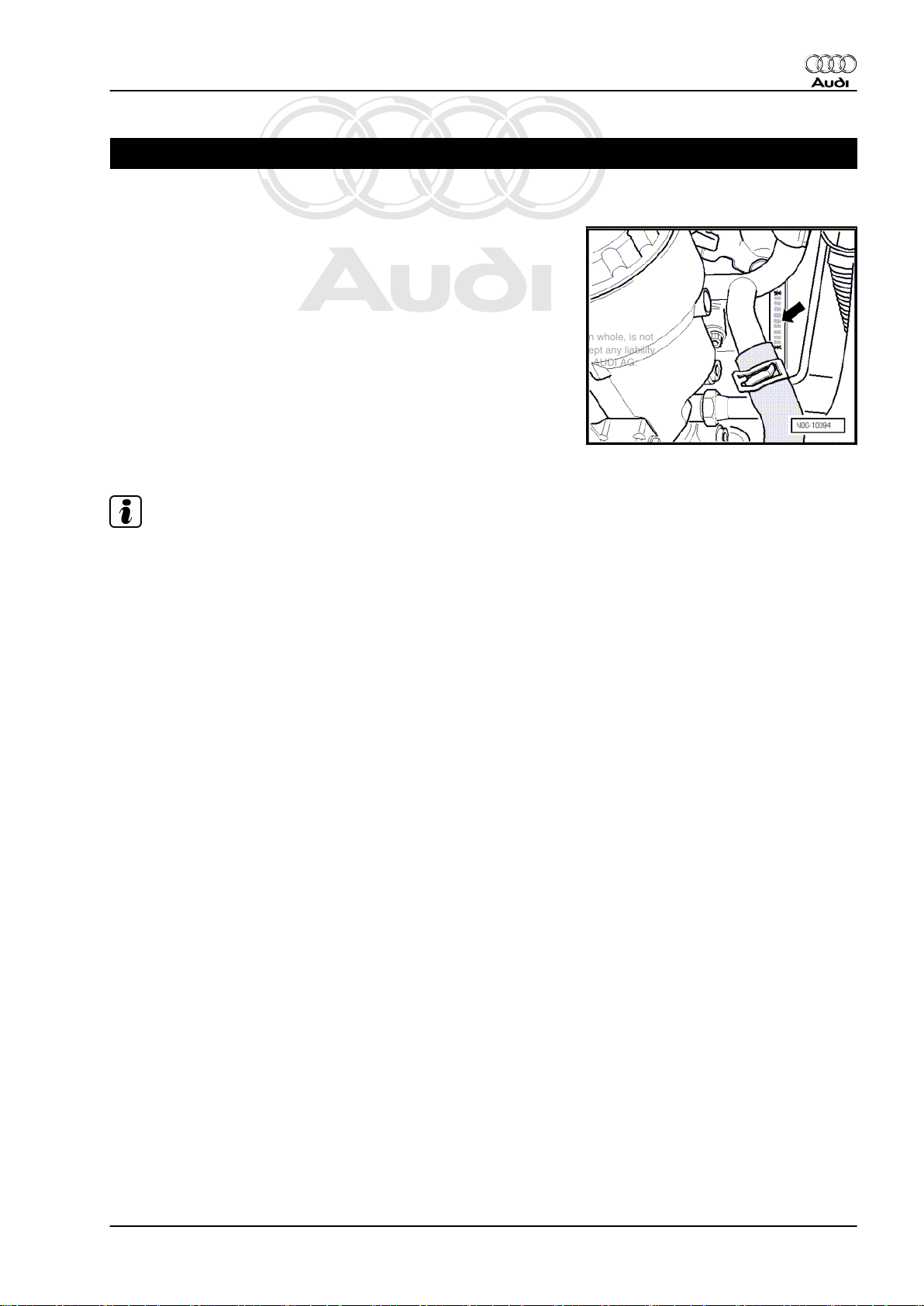
1 Engine number
♦ The engine number (“Engine code” and “Serial number”)
-arrow- can be found at the front of the joint between engine
and gearbox.
♦ There is also a sticker on the toothed belt cover showing the
“Engine code” and “Serial number”.
♦ Starting with the letter “C”, the engine codes consist of 4 let‐
ters.
♦ The first 3 characters of the engine code stand for the engine
capacity and the mechanical construction and design. They
are stamped on the cylinder block, together with the serial
number.
♦ The 4th character indicates the power output and torque of the
engine, and is determined by the engine control unit.
Audi TT 2007 ➤
Note
♦
The 4-character engine code can be found on the type plate
(in versions for some countries only) and on the vehicle data
sticker and the engine control unit.
♦
Fitting locations of the type plate (certain countries only) and
the vehicle data sticker ⇒ Maintenance ; Booklet 810 .
1. Engine number 1
Page 8
Protected by copyright. Copying for private or commercial purposes, in part or in whole, is not
permitted unless authorised by AUDI AG. AUDI AG does not guarantee or accept any liability
with respect to the correctness of information in this document. Copyright by AUDI AG.
Audi TT 2007 ➤
4-cylinder TDI engine (2.0 ltr. 4-valve common rail), mechanics - Edition 04.2010
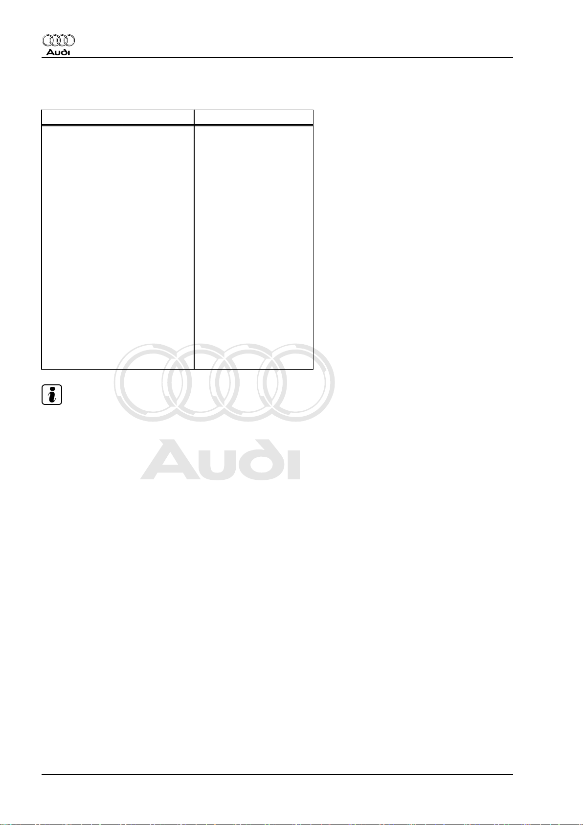
2 Engine data
Code letters CBBB
Capacity ltr. 1.968
Power output kW at rpm 125/4200
Torque Nm at rpm 350/1750 … 2500
Bore ∅ in mm 81.0
Stroke mm 95.5
Compression ra‐
tio
CN not less than 51
Firing order
Emission standards EU4 plus
Exhaust gas recirculation yes
Exhaust gas temperature control yes
Turbocharging/supercharging Turbocharger
Glow plugs Steel glow plugs
Charge air cooling yes
Lambda control 1 Lambda probe
Particulate filter yes
Valves per cylinder 4
16.5
1-3-4-2
Note
Audi TT models with a TDI engine (2.0 ltr. 4-valve common rail)
are always equipped with steel glow plugs.
2 Rep. Gr.00 - Technical data
Page 9
Protected by copyright. Copying for private or commercial purposes, in part or in whole, is not
permitted unless authorised by AUDI AG. AUDI AG does not guarantee or accept any liability
with respect to the correctness of information in this document. Copyright by AUDI AG.
4-cylinder TDI engine (2.0 ltr. 4-valve common rail), mechanics - Edition 04.2010
3 Safety precautions
When working on the fuel system note the following warnings:
WARNING
Risk of injury - fuel system operates under pressure.
♦ Wrap a clean cloth around the connection before opening
the fuel system. Then release pressure by carefully loos‐
ening the connection.
♦ Wear protective gloves.
♦ Wear safety goggles.
The fuel can become extremely hot. This can cause injuries.
♦ In extreme cases the temperature of the fuel lines and the
fuel can be up to 100 °C after the engine is switched off.
Allow the fuel to cool down before disconnecting the lines
- danger of scalding.
♦ Wear protective gloves.
♦ Wear safety goggles.
Audi TT 2007 ➤
Observe the following points to prevent personal injuries and
damage to the injection and glow plug system:
♦ Always switch off the ignition before connecting or discon‐
necting tester cables or electrical wiring for the injection or
glow plug system.
♦ Always switch off ignition before washing engine.
♦ Faults are stored in engine control unit if electrical connectors
have been unplugged:
– “Interrogate fault memory” in “Vehicle self-diagnosis”.
Caution
To prevent damage to the electronic components when dis‐
connecting the battery:
♦ Observe notes on procedure for disconnecting the battery.
♦ Always switch off the ignition before disconnecting the
battery.
– Disconnect battery ⇒ Rep. Gr. 27 .
3. Safety precautions 3
Page 10
Protected by copyright. Copying for private or commercial purposes, in part or in whole, is not
permitted unless authorised by AUDI AG. AUDI AG does not guarantee or accept any liability
with respect to the correctness of information in this document. Copyright by AUDI AG.
Audi TT 2007 ➤
4-cylinder TDI engine (2.0 ltr. 4-valve common rail), mechanics - Edition 04.2010
When working on the cooling system note the following warnings:
WARNING
Hot steam/hot coolant can escape - risk of scalding.
♦ The cooling system is under pressure when the engine is
hot.
♦ To allow pressure to dissipate, cover filler cap coolant on
expansion tank with cloth and open carefully.
Risk of injury as the radiator fans may start up automatically.
♦ Unplug electrical connectors before starting to work in the
area of radiator cowl.
Caution
Overheating can occur if the filler cap is not fitted properly.
♦ Firmly close filler cap on coolant expansion tank.
Note the following if testers and measuring instruments have to
be used during a road test:
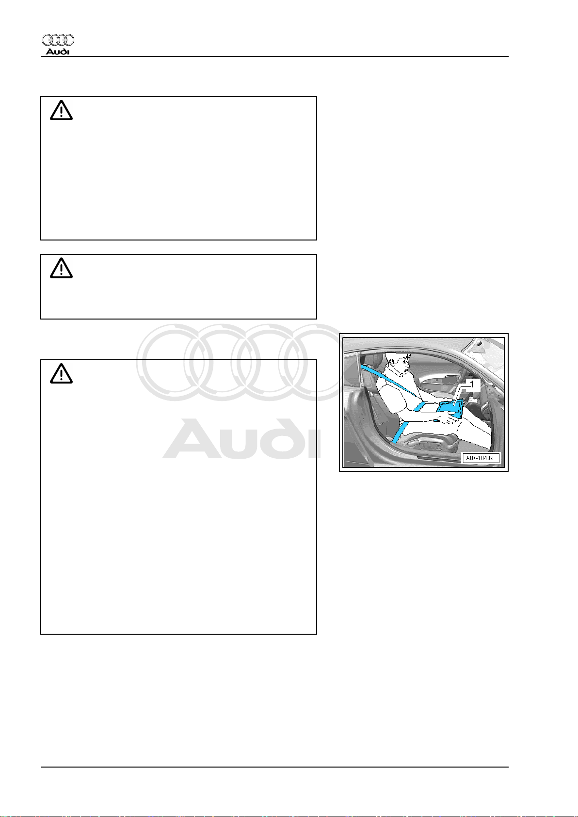
WARNING
Accidents can be caused if the driver is distracted by test
equipment while road-testing, or if test equipment is not prop‐
erly secured.
Persons sitting in the front passenger's seat could be injured if
the airbag is triggered in an accident.
• The use of test equipment while driving causes distraction.
• There is an increased risk of injury if test equipment is not
secured.
TT Coupé:
Test equipment must always be secured on the rear seat with
a strap and operated from the rear seat by a second person.
TT Roadster:
♦ Move the passenger's seat back as far as it will go.
♦ Use only vehicle diagnosis and service information sys‐
tem -VAS 5052- or diagnosis system -VAS 5053- .
♦ The test equipment -1- must rest flat on the passenger's
thighs (as shown in illustration) and must be operated by
the passenger.
4 Rep. Gr.00 - Technical data
Page 11

Protected by copyright. Copying for private or commercial purposes, in part or in whole, is not
permitted unless authorised by AUDI AG. AUDI AG does not guarantee or accept any liability
with respect to the correctness of information in this document. Copyright by AUDI AG.
4-cylinder TDI engine (2.0 ltr. 4-valve common rail), mechanics - Edition 04.2010
4 General repair instructions
4.1 Rules for cleanliness when working on fuel supply system, injection system and turbocharger
Even small amounts of dirt can cause malfunctions. For this rea‐
son, please observe the following rules when working on the fuel
supply system, injection system and turbocharger:
♦ Carefully clean connection points and the surrounding area
with engine cleaner or brake cleaner and dry thoroughly before
opening.
♦ Seal off open pipes/lines and connections using engine bung
set -VAS 6122- .
♦ Place parts that have been removed on a clean surface and
cover them over. Do not use fluffy cloths.
♦ Carefully cover or seal open components if repairs cannot be
carried out immediately.
♦ Only install clean components; replacement parts should only
be unpacked immediately prior to installation. Do not use parts
that have not been stored in the proper packaging (e.g. in tool
boxes etc.).
♦ When the system is open: Do not work with compressed air.
Do not move the vehicle unless absolutely necessary.
♦ Protect unplugged electrical connectors against dirt and mois‐
ture and make sure connections are dry when attaching.
Audi TT 2007 ➤
4.2 Checking for leaks in the fuel system
Procedure
– Allow engine to run for several minutes at moderate rpm.
– Switch off ignition.
– Check complete fuel system for leaks.
– If leaks are found although the connections have been tight‐
ened to the correct torque, the relevant component must be
renewed.
– Road-test vehicle and accelerate with full throttle at least once.
– Then inspect high-pressure section of fuel system again for
leaks.
4.3 Contact corrosion!
Contact corrosion can occur if unsuitable fasteners are used (e.g.
bolts, nuts, washers, etc.).
For this reason, only fasteners with a special surface coating are
used.
Additionally, all rubber and plastic parts and all adhesives are
made of non-conductive materials.
Always install new parts if you are not sure whether used parts
can be re-fitted ⇒ Electronic parts catalogue .
Note the following:
♦ We recommend using only genuine replacement parts; these
have been tested and are compatible with aluminium.
4. General repair instructions 5
Page 12
Protected by copyright. Copying for private or commercial purposes, in part or in whole, is not
permitted unless authorised by AUDI AG. AUDI AG does not guarantee or accept any liability
with respect to the correctness of information in this document. Copyright by AUDI AG.
Audi TT 2007 ➤
4-cylinder TDI engine (2.0 ltr. 4-valve common rail), mechanics - Edition 04.2010
♦ We recommend the use of Audi accessories.
♦ Damage caused by contact corrosion is not covered under
warranty.
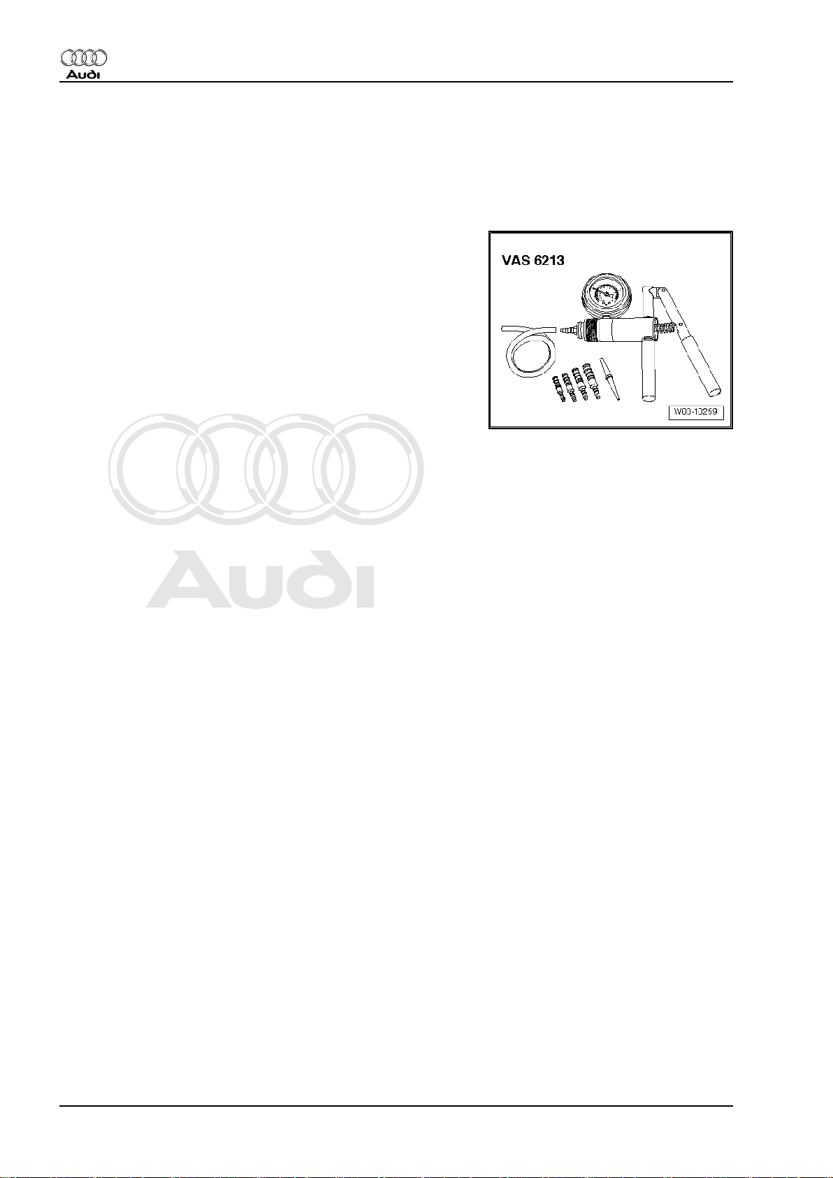
4.4 Checking vacuum system
Special tools and workshop equipment required
♦ Hand vacuum pump -VAS 6213-
Procedure
– Check all vacuum lines in the complete vacuum system for:
♦ Cracks
♦ Traces of animal bites
♦ Kinked or crushed lines
♦ Lines porous or leaking
– Check vacuum line to solenoid valve and from solenoid valve
to corresponding component.
– If a fault is stored in the fault memory, check the vacuum lines
leading to the corresponding component and also check the
remaining vacuum lines in the system.
– If it is not possible to build up pressure with the hand vacuum
pump -VAS 6213- or if the pressure drops again immediately,
check the hand vacuum pump and connecting hoses for leaks.
4.5 Routing and attachment of pipes, hoses and wiring
Mark hydraulic lines, vacuum lines and electrical wiring before
removal so they can be re-installed in the original positions and
correctly connected. Make sketches or take photographs if nec‐
essary.
6 Rep. Gr.00 - Technical data
Page 13
Protected by copyright. Copying for private or commercial purposes, in part or in whole, is not
permitted unless authorised by AUDI AG. AUDI AG does not guarantee or accept any liability
with respect to the correctness of information in this document. Copyright by AUDI AG.
4-cylinder TDI engine (2.0 ltr. 4-valve common rail), mechanics - Edition 04.2010
10 – Removing and installing engine
1 Removing engine
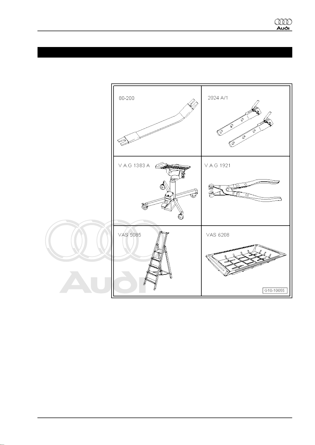
Special tools and workshop
equipment required
♦ Removal lever -80 - 200-
♦ Extension -2024 A /1-
♦ Engine and gearbox jack -
V.A.G 1383 A-
♦ Hose clip pliers -
V.A.G 1921-
♦ Stepladder -VAS 5085-
♦ Drip tray for workshop hoist
-VAS 6208-
Audi TT 2007 ➤
1. Removing engine 7
Page 14
Protected by copyright. Copying for private or commercial purposes, in part or in whole, is not
permitted unless authorised by AUDI AG. AUDI AG does not guarantee or accept any liability
with respect to the correctness of information in this document. Copyright by AUDI AG.
Audi TT 2007 ➤
4-cylinder TDI engine (2.0 ltr. 4-valve common rail), mechanics - Edition 04.2010
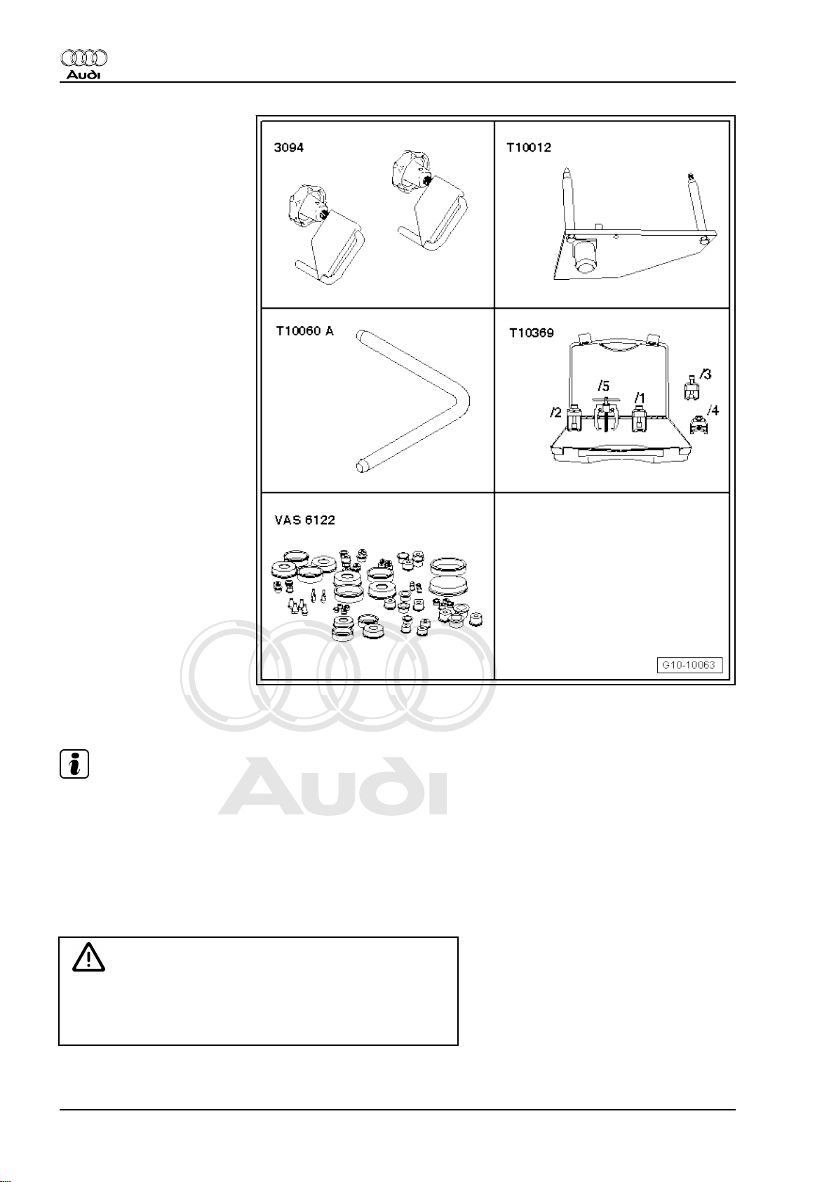
♦ Hose clamps for hoses up
to 25 mm -3094-
♦ Engine bracket -T10012-
♦ Locking pin -T10060 A-
♦ Puller -T10369-
♦ Engine bung set -VAS
6122-
♦ Safety goggles
♦ Protective gloves
Procedure
Note
♦
The engine is removed from underneath together with the
gearbox.
♦
Collect drained coolant in a clean container for re-use or dis‐
posal.
♦
Fit cable ties in the original positions when installing.
♦
Fit heat insulation sleeves in the original positions when in‐
stalling.
Caution
To prevent damage to the electronic components when dis‐
connecting the battery:
♦ Observe notes on procedure for disconnecting the battery.
8 Rep. Gr.10 - Removing and installing engine
Page 15
Protected by copyright. Copying for private or commercial purposes, in part or in whole, is not
permitted unless authorised by AUDI AG. AUDI AG does not guarantee or accept any liability
with respect to the correctness of information in this document. Copyright by AUDI AG.
4-cylinder TDI engine (2.0 ltr. 4-valve common rail), mechanics - Edition 04.2010
– Take out luggage compartment floor covering.
– Take out luggage compartment floor mat.
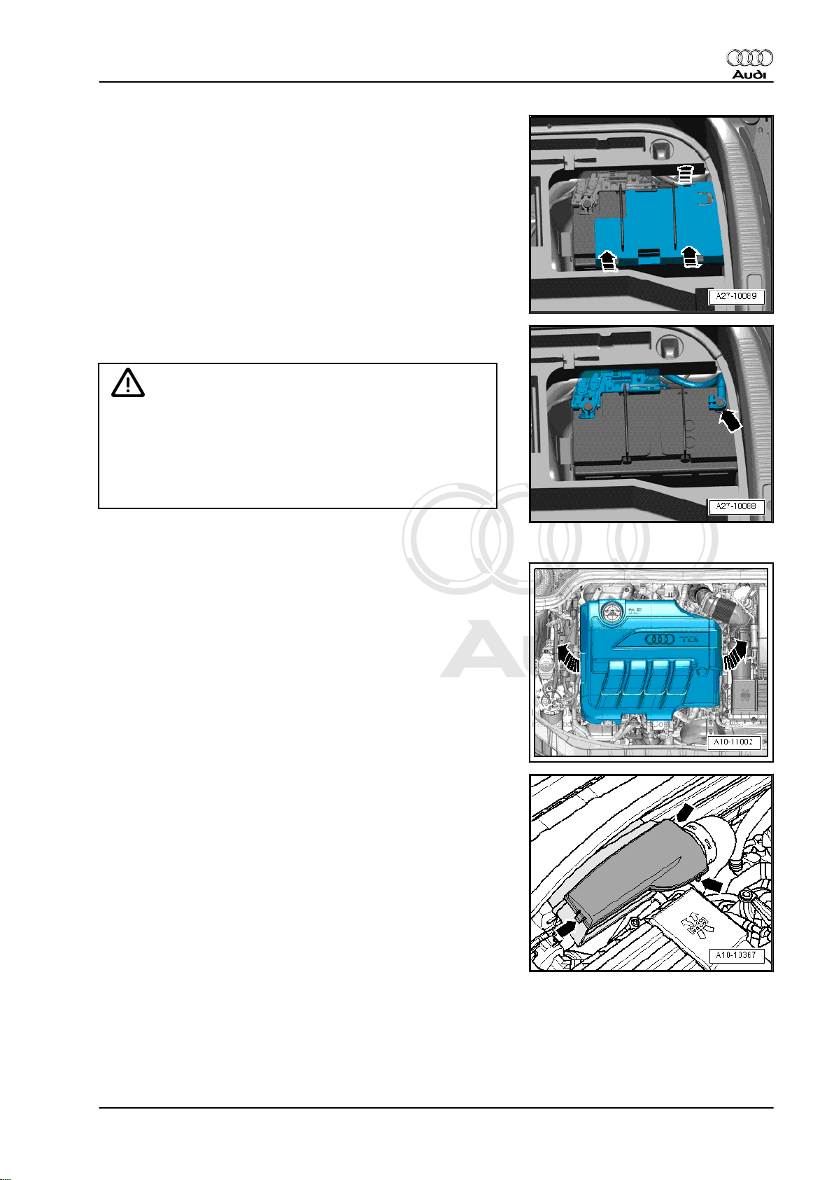
– Remove rear cross panel trim if cover for negative battery ter‐
minal is located behind rear cross panel trim ⇒ Rep. Gr. 70 .
– Release retaining clips -arrows- and detach cover for negative
terminal.
– Loosen nut a few turns and disconnect battery clamp on earth
wire -arrow- from battery terminal.
WARNING
Hot steam/hot coolant can escape - risk of scalding.
♦ The cooling system is under pressure when the engine is
hot.
♦ To allow pressure to dissipate, cover filler cap on coolant
expansion tank with cloth and open carefully.
Audi TT 2007 ➤
– Open filler cap on coolant expansion tank.
– Remove engine cover panel -arrows-.
– Pull cover off air duct (release clips on sides) -arrows-.
1. Removing engine 9
Page 16
Protected by copyright. Copying for private or commercial purposes, in part or in whole, is not
permitted unless authorised by AUDI AG. AUDI AG does not guarantee or accept any liability
with respect to the correctness of information in this document. Copyright by AUDI AG.
Audi TT 2007 ➤
4-cylinder TDI engine (2.0 ltr. 4-valve common rail), mechanics - Edition 04.2010
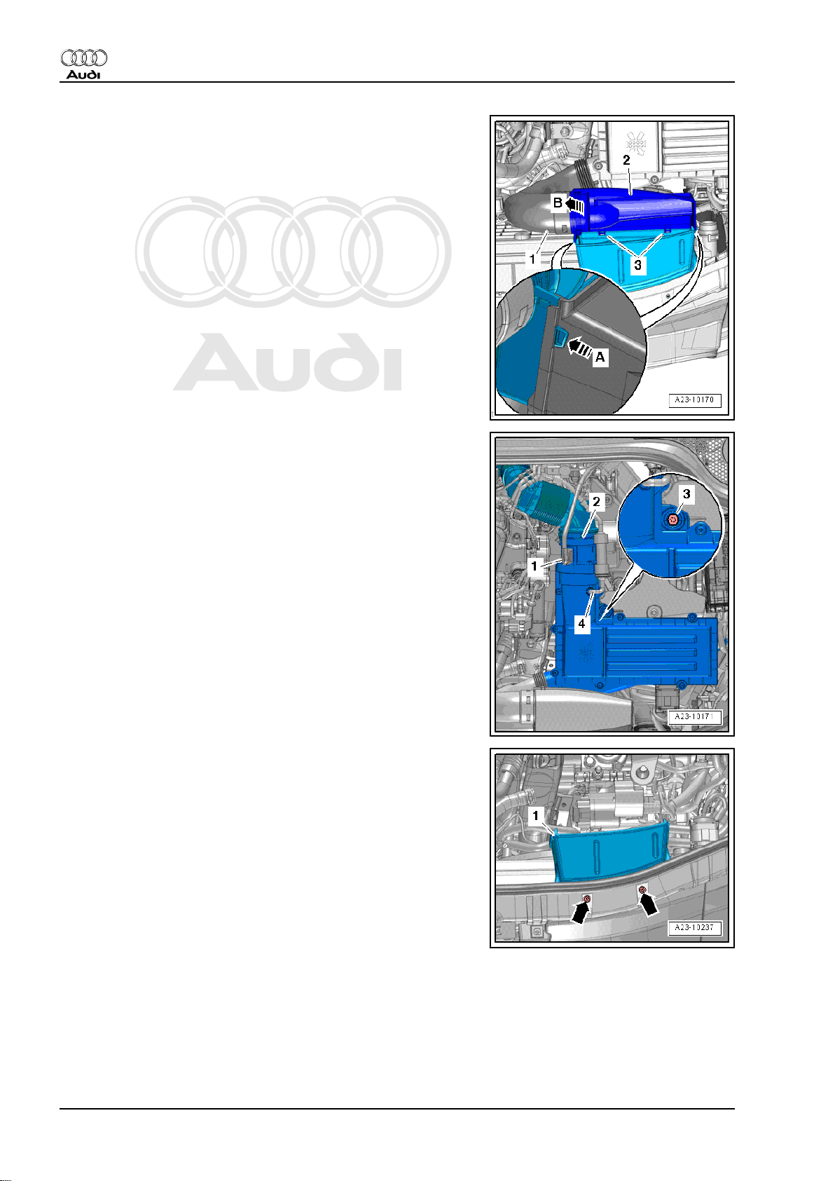
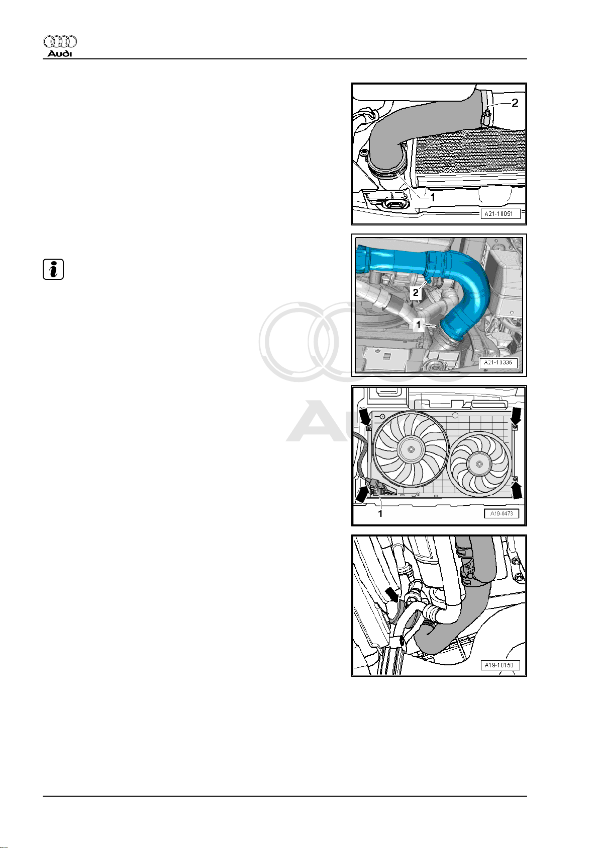
– Release clips on left and right -arrow A- and unclip air duct at
bottom -2-.
– Swivel air duct (bottom) slightly to the rear and detach air duct
(bottom) from retainers -3-.
– Detach air pipe -1- from air duct (bottom) -arrow B-.
– Unplug electrical connector -1- from air mass meter -G70- .
– Detach hose -4-.
– Release hose clip -2- and detach air hose.
– Unscrew bolt -3- and remove air cleaner housing.
– Remove bolts -arrows- and detach air duct -1- from lock car‐
rier.
10 Rep. Gr.10 - Removing and installing engine
Page 17
Protected by copyright. Copying for private or commercial purposes, in part or in whole, is not
permitted unless authorised by AUDI AG. AUDI AG does not guarantee or accept any liability
with respect to the correctness of information in this document. Copyright by AUDI AG.
4-cylinder TDI engine (2.0 ltr. 4-valve common rail), mechanics - Edition 04.2010
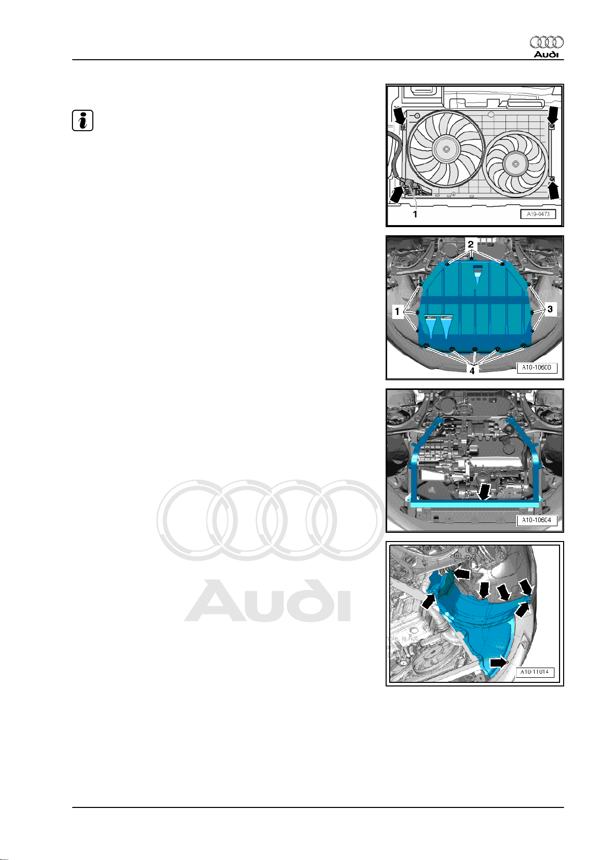
– Remove bolts -top arrows- for radiator cowl.
Note
The bolts -bottom arrows- are removed at a later stage.
– Remove both front wheels.
– Release fasteners -1 ... 4- and remove centre noise insulation.
Audi TT 2007 ➤
– Only on TT Roadster: Remove noise insulation frame
-arrow- ⇒ Rep. Gr. 50 .
– Release fasteners -arrows- and remove wheel housing liner
(bottom section) on both sides.
1. Removing engine 11
Page 18
Protected by copyright. Copying for private or commercial purposes, in part or in whole, is not
permitted unless authorised by AUDI AG. AUDI AG does not guarantee or accept any liability
with respect to the correctness of information in this document. Copyright by AUDI AG.
Audi TT 2007 ➤
4-cylinder TDI engine (2.0 ltr. 4-valve common rail), mechanics - Edition 04.2010
– Release hose clip -2-, lift retaining clip -1- and remove air hose.
– Release hose clip -2-, lift retaining clip -1- and remove air hose.
Note
To prevent coolant from entering, seal off connection on charge
air cooler with a clean plug from engine bung set -VAS 6122- .
– Unplug electrical connector -1-.
– Remove bolts -bottom arrows- and take out air cowl down‐
wards.
– Place drip tray for workshop hoist -VAS 6208- beneath engine.
– Lift retaining clip -arrow-, disconnect coolant hose (bottom
right) from radiator and drain off coolant.
12 Rep. Gr.10 - Removing and installing engine
Page 19

Protected by copyright. Copying for private or commercial purposes, in part or in whole, is not
permitted unless authorised by AUDI AG. AUDI AG does not guarantee or accept any liability
with respect to the correctness of information in this document. Copyright by AUDI AG.
4-cylinder TDI engine (2.0 ltr. 4-valve common rail), mechanics - Edition 04.2010
– Open hose clip -arrow-, disconnect coolant hose (bottom)
leading to pump for exhaust gas recirculation cooler -V400and drain off coolant.
– Remove bolts -bottom arrows- on rear side of radiator.
Note
The bolts -top arrows- are removed at a later stage.
Audi TT 2007 ➤
– As an additional step, open hose clip -arrow-, disconnect cool‐
ant hose at top of engine oil cooler and drain off remaining
coolant.
– Remove bolts -arrows- and detach bracket -1- for air cleaner
housing.
1. Removing engine 13
Page 20
Protected by copyright. Copying for private or commercial purposes, in part or in whole, is not
permitted unless authorised by AUDI AG. AUDI AG does not guarantee or accept any liability
with respect to the correctness of information in this document. Copyright by AUDI AG.
Audi TT 2007 ➤
4-cylinder TDI engine (2.0 ltr. 4-valve common rail), mechanics - Edition 04.2010
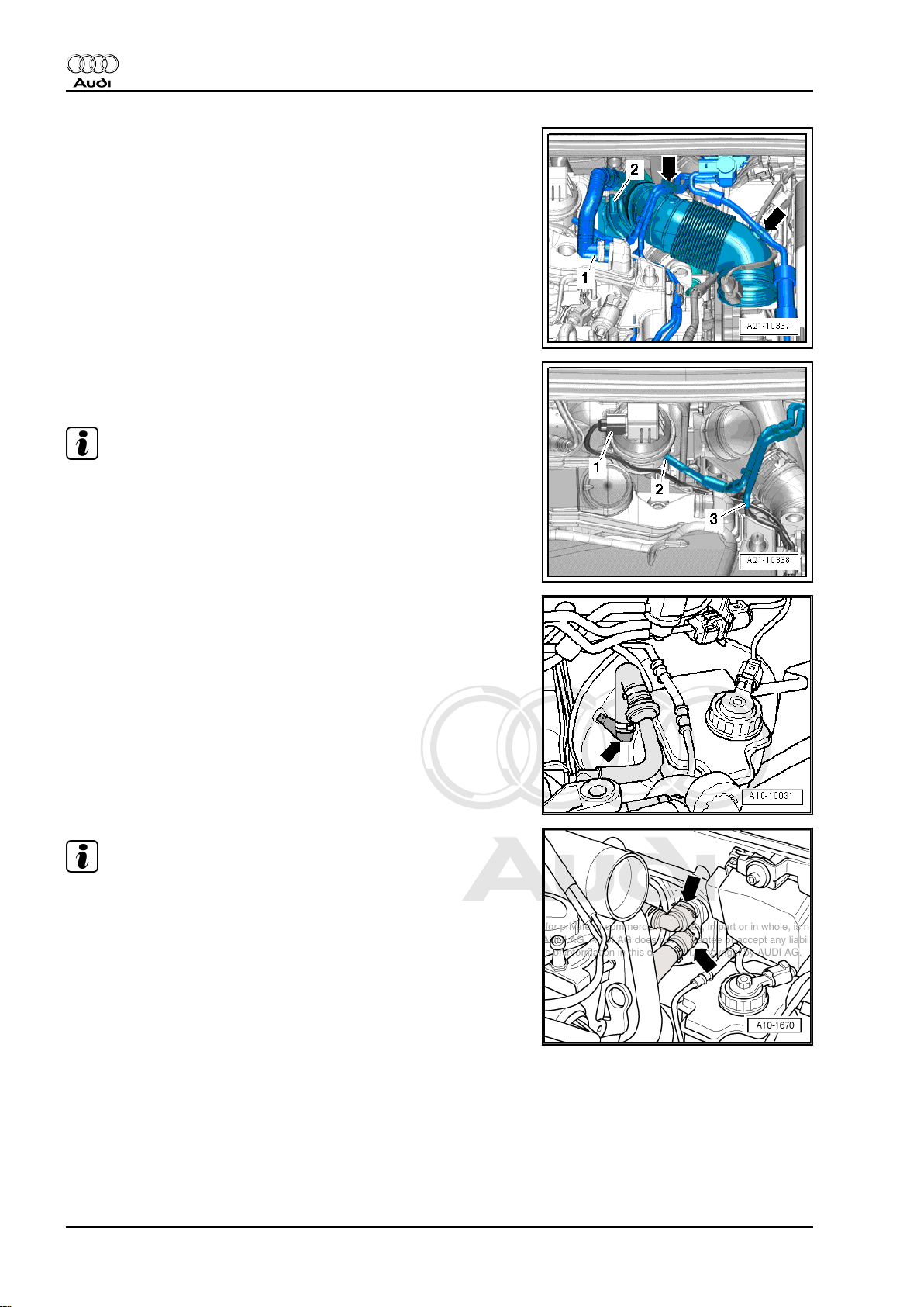
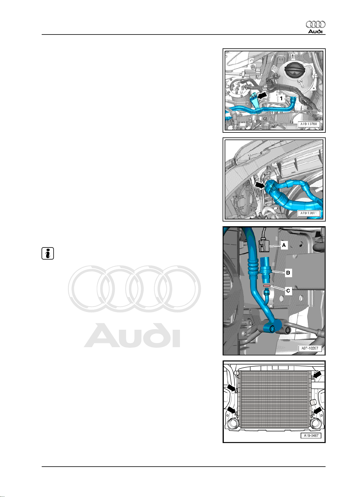
– Press release tabs and disconnect crankcase breather hose
-1- from cylinder head cover.
– Move clear vacuum hoses -arrows- at air pipe.
– Loosen hose clip -2- and detach air pipe.
– Detach vacuum hose -2- from vacuum unit of turbocharger.
– Disconnect vacuum hose -3-.
Note
Disregard -item 1-.
– Detach vacuum hose -arrow- from brake servo.
Note
Place a cloth underneath heat exchanger to catch escaping cool‐
ant.
– Lift retaining clips -arrows- and detach coolant hoses from
heat exchanger.
14 Rep. Gr.10 - Removing and installing engine
Page 21
Protected by copyright. Copying for private or commercial purposes, in part or in whole, is not
permitted unless authorised by AUDI AG. AUDI AG does not guarantee or accept any liability
with respect to the correctness of information in this document. Copyright by AUDI AG.
4-cylinder TDI engine (2.0 ltr. 4-valve common rail), mechanics - Edition 04.2010
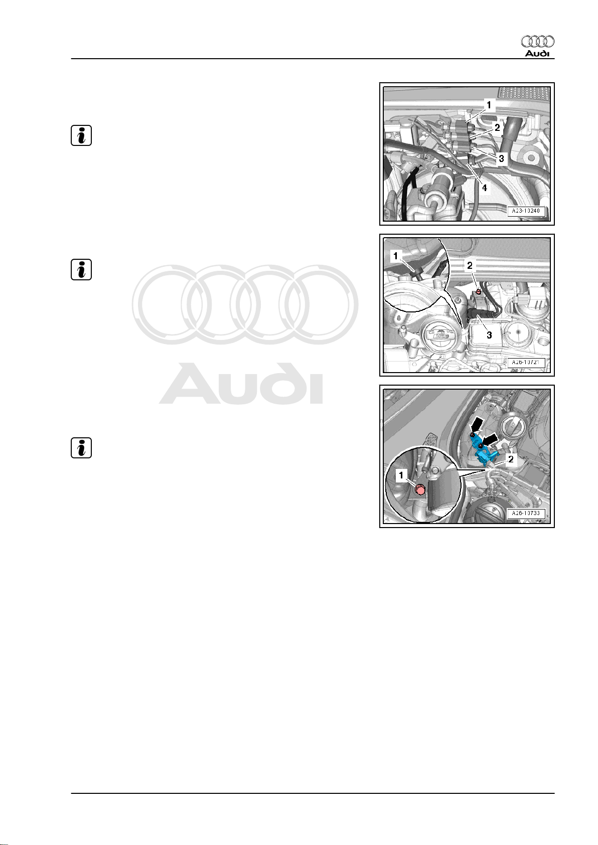
– Detach electrical connector -1- from bracket and unplug.
– Move clear electrical wiring.
Note
Disregard -items 2, 3 and 4-.
– Slacken bolt -2- and remove clamp.
Note
Disregard -items 1, 3-.
Audi TT 2007 ➤
– Unplug electrical connector -2- on exhaust gas pressure sen‐
sor 1 -G450- .
– Remove bolt -1-.
Note
Disregard -arrows-.
1. Removing engine 15
Page 22
Protected by copyright. Copying for private or commercial purposes, in part or in whole, is not
permitted unless authorised by AUDI AG. AUDI AG does not guarantee or accept any liability
with respect to the correctness of information in this document. Copyright by AUDI AG.
Audi TT 2007 ➤
4-cylinder TDI engine (2.0 ltr. 4-valve common rail), mechanics - Edition 04.2010
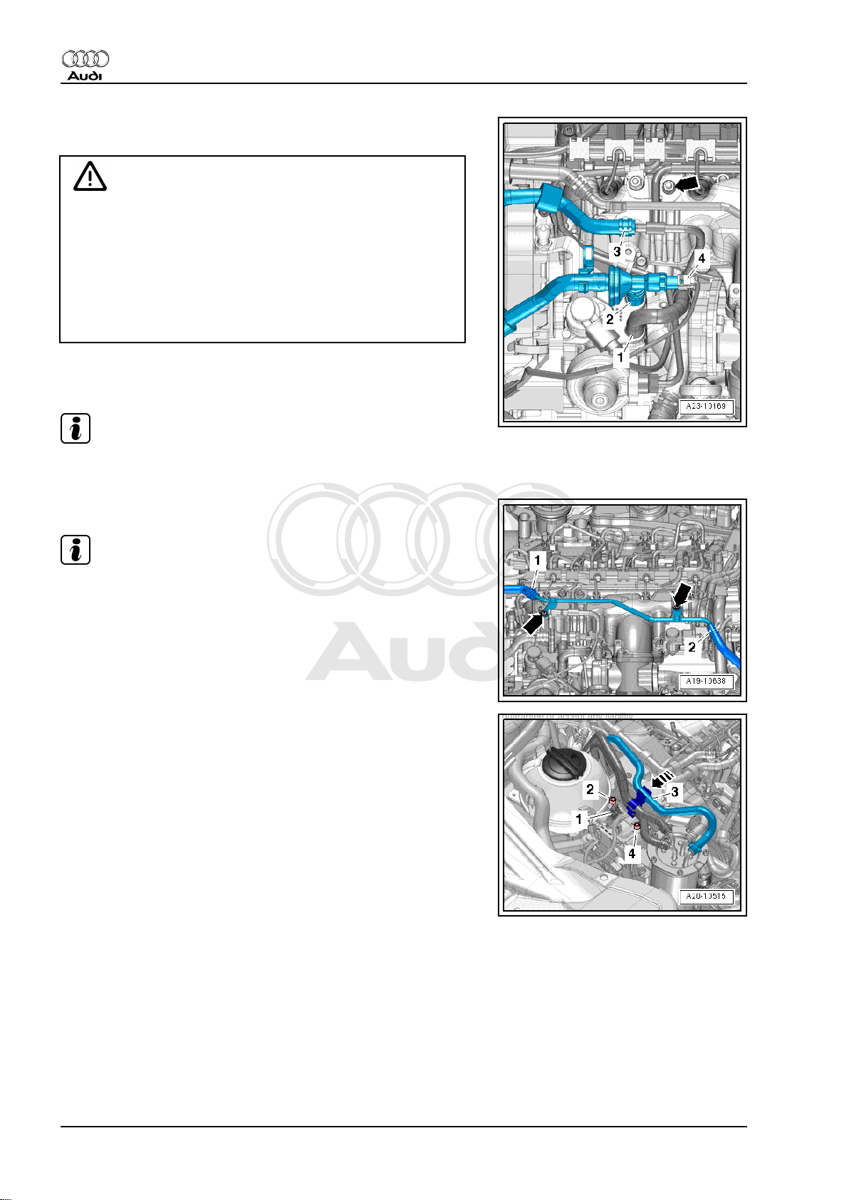
– Unplug electrical connector -4- on fuel temperature sender -
G81- .
WARNING
The fuel can become extremely hot. This can cause injuries.
♦ In extreme cases the temperature of the fuel lines and the
fuel can be up to 100 °C after the engine is switched off.
Allow the fuel to cool down before disconnecting the lines
- danger of scalding.
♦ Wear protective gloves.
♦ Wear safety goggles.
– Release hose clips -2- and -3- and disconnect fuel supply hose
and fuel return hose.
Note
Disregard items marked -1- and -arrow-.
– Release hose clip -1- and detach coolant hose.
Note
Ignore items marked -2- and -arrows-.
– Disengage fuel hose -3- at bracket.
– Pull off bracket for fuel lines towards right -arrow- and move
clear to one side.
– Unplug electrical connector -1- at supplementary fuel pump -
V393- .
– Remove bolts -2- and -4-, detach bracket with supplementary
fuel pump -V393- and move clear to one side.
16 Rep. Gr.10 - Removing and installing engine
Page 23
Protected by copyright. Copying for private or commercial purposes, in part or in whole, is not
permitted unless authorised by AUDI AG. AUDI AG does not guarantee or accept any liability
with respect to the correctness of information in this document. Copyright by AUDI AG.
4-cylinder TDI engine (2.0 ltr. 4-valve common rail), mechanics - Edition 04.2010
– Release hose clip -1-, detach coolant hose from coolant ex‐
pansion tank and move coolant hose clear -arrow-.
– Lift retaining clip -arrow- and disconnect coolant hose (top left)
from radiator.
Audi TT 2007 ➤
– Unplug electrical connector -A- at high-pressure sender -G65-
-item B-.
Note
Disregard -item C-.
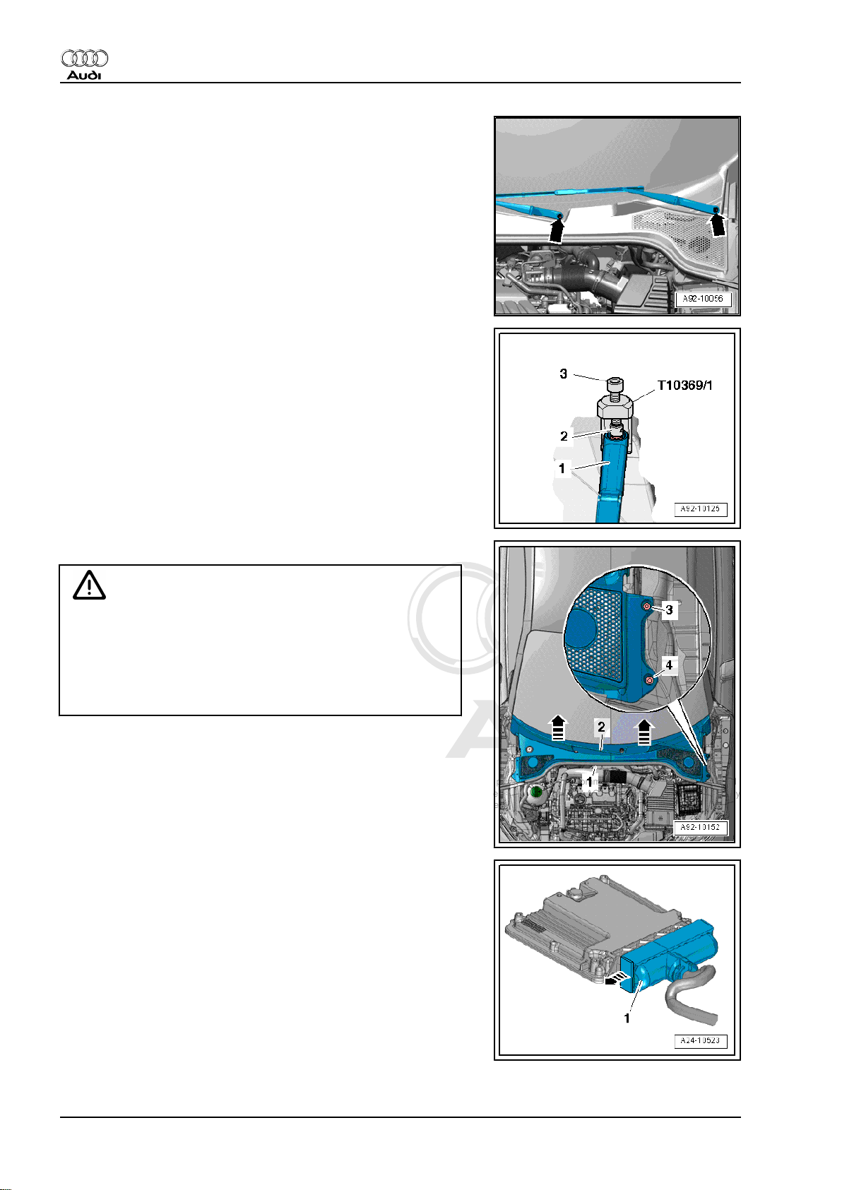
– Remove bolts -top arrows- at rear and lift out radiator.
1. Removing engine 17
Page 24
Protected by copyright. Copying for private or commercial purposes, in part or in whole, is not
permitted unless authorised by AUDI AG. AUDI AG does not guarantee or accept any liability
with respect to the correctness of information in this document. Copyright by AUDI AG.
Audi TT 2007 ➤
4-cylinder TDI engine (2.0 ltr. 4-valve common rail), mechanics - Edition 04.2010
– Pry off caps on windscreen wiper arms with a screwdriver.
– Slacken nuts -arrows- one turn.
– Apply puller -T10369/1- to wiper arm -1- as shown in illustra‐
tion.
– Apply thrust piece -2- onto wiper shaft.
– Turn bolt -3- in clockwise direction until wiper arm is pulled off
wiper shaft.
– Remove nuts and detach windscreen wiper arms.
– Remove seal -1-.
Caution
Risk of damage to plenum chamber cover.
♦ Apply a small quantity of soap solution to transition be‐
tween windscreen and plenum chamber cover -2-. Then,
starting at edge of windscreen, carefully pull plenum
chamber cover upwards off retainer at windscreen
-arrows-.
– Detach plenum chamber cover by pulling it carefully off re‐
tainer at windscreen.
– Move clear engine wiring harness at rear of plenum chamber
partition panel.
– Remove engine control unit ⇒ Rep. Gr. 23 .
– Release electrical connector -1- for engine wiring harness
-arrow- and detach.
18 Rep. Gr.10 - Removing and installing engine
Page 25
Protected by copyright. Copying for private or commercial purposes, in part or in whole, is not
permitted unless authorised by AUDI AG. AUDI AG does not guarantee or accept any liability
with respect to the correctness of information in this document. Copyright by AUDI AG.
4-cylinder TDI engine (2.0 ltr. 4-valve common rail), mechanics - Edition 04.2010
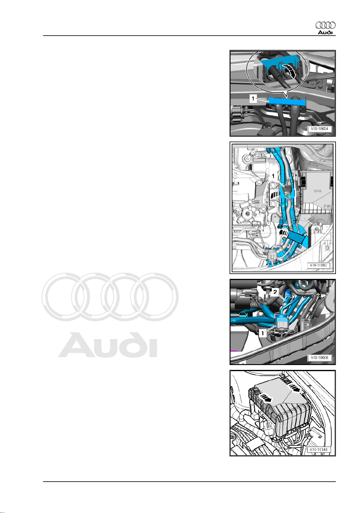
– Release wiring protector -1- for engine wiring harness
-arrow- and lift off.
– Move clear and unplug electrical connector -1-.
– Open wiring duct bracket -arrows-, use removal lever -80 -
200- to unclip wiring and press wiring to side.
– Unclip wiring duct.
Audi TT 2007 ➤
– Unclip electrical connector -1- from bracket and unplug.
– Open wiring duct bracket located underneath.
– Unclip wiring harness for engine control unit from wiring duct.
– Place engine wiring harness with engine control unit on top of
engine.
– Secure engine control unit to prevent it falling.
– Unclip electrical connector -2- from bracket and unplug.
– Slide the two clips in the direction of the -arrows- and remove
cover from electronics box in engine compartment.
1. Removing engine 19
Page 26
Protected by copyright. Copying for private or commercial purposes, in part or in whole, is not
permitted unless authorised by AUDI AG. AUDI AG does not guarantee or accept any liability
with respect to the correctness of information in this document. Copyright by AUDI AG.
Audi TT 2007 ➤
4-cylinder TDI engine (2.0 ltr. 4-valve common rail), mechanics - Edition 04.2010
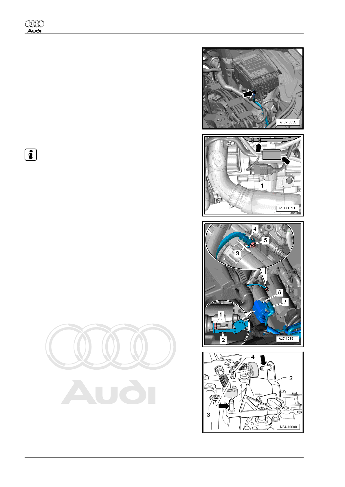
– Remove nut -arrow-, detach terminal 30 wire from electronics
box in engine compartment and move it clear.
– Unplug electrical connector -1-.
Note
Disregard -arrows-.
– Unplug electrical connector -7- (push retainer to the rear and
press down release catch).
– Push back protective sleeve -6-.
– Remove nut -1- and detach B+ wire -item 2- from starter sol‐
enoid switch.
– Remove nut -5- and detach earth wire -4-.
– Remove top starter bolt -3-.
– Detach securing clip -3- for gear selector cable from gearbox
selector lever -1- and pull cable off pin -arrow-.
Metal selector relay lever:
– Detach securing clip -4- for gate selector cable from selector
relay lever -2- and pull cable off pin -arrow-.
20 Rep. Gr.10 - Removing and installing engine
Page 27
Protected by copyright. Copying for private or commercial purposes, in part or in whole, is not
permitted unless authorised by AUDI AG. AUDI AG does not guarantee or accept any liability
with respect to the correctness of information in this document. Copyright by AUDI AG.
4-cylinder TDI engine (2.0 ltr. 4-valve common rail), mechanics - Edition 04.2010
Plastic selector relay lever:
• To prevent damage to gate selector cable, cable end-piece
must be detached from gate selector cable before removing.
– Pull locking device forwards onto stop -arrow 1- and lock by
turning anti-clockwise -arrow 2-.
– Press selector relay lever towards front -arrow 3-.
All vehicles (continued):
– Remove cable support bracket -arrows- from gearbox and
place to one side (selector cables remain fitted).
Audi TT 2007 ➤
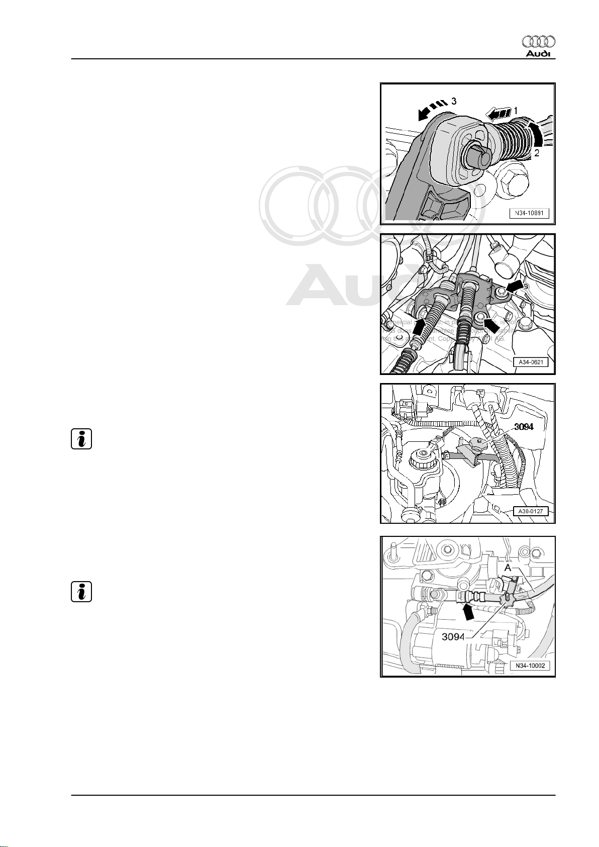
– If a plastic pipe is installed between clutch master cylinder and
slave cylinder, clamp off supply hose to clutch master cylinder
using hose clamp -3094- .
Note
♦
Make sure brake fluid does not come into contact with starter
or gearbox when performing the following operations. If it
does, clean affected area thoroughly.
♦
Seal off open pipes/lines and connections with clean plugs
from engine bung set -VAS 6122- to prevent dirt from entering.
– If a pipe/hose assembly is installed between clutch master
cylinder and slave cylinder, clamp off hose -A- using hose
clamp for hoses up to 25 mm -3094- .
Note
Disregard -arrow-.
1. Removing engine 21
Page 28
Protected by copyright. Copying for private or commercial purposes, in part or in whole, is not
permitted unless authorised by AUDI AG. AUDI AG does not guarantee or accept any liability
with respect to the correctness of information in this document. Copyright by AUDI AG.
Audi TT 2007 ➤
4-cylinder TDI engine (2.0 ltr. 4-valve common rail), mechanics - Edition 04.2010
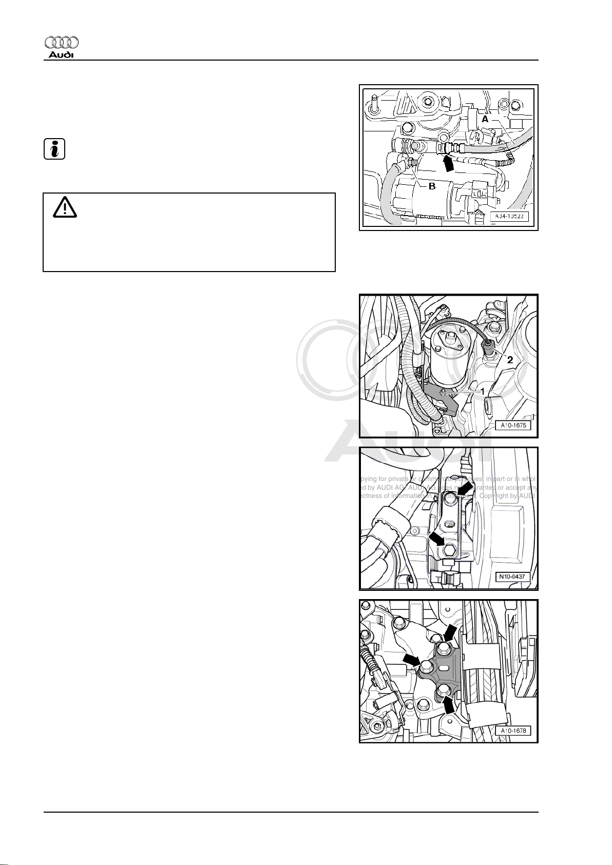
– Pull out clip -arrow- as far as stop.
– Pull plastic pipe or pipe/hose assembly -A- out of clutch slave
cylinder and seal end of pipe.
Note
Disregard -item B-.
Caution
Risk of contamination by escaping brake fluid.
♦ Do not operate clutch pedal after detaching pipe from
bleeder screw on clutch slave cylinder.
– Unplug electrical connector -2- for reversing light switch -F4- .
– Remove nut -1- and press bracket to side.
– Remove bottom starter bolt and detach starter.
– Loosen bolts -arrows- for assembly mounting (engine end)
approx. 2 turns.
– Loosen bolts -arrows- for assembly mounting (gearbox end)
approx. 2 turns.
22 Rep. Gr.10 - Removing and installing engine
Page 29
Protected by copyright. Copying for private or commercial purposes, in part or in whole, is not
permitted unless authorised by AUDI AG. AUDI AG does not guarantee or accept any liability
with respect to the correctness of information in this document. Copyright by AUDI AG.
4-cylinder TDI engine (2.0 ltr. 4-valve common rail), mechanics - Edition 04.2010
Caution
If a used belt runs in the opposite direction when it is refitted,
this can cause breakage.
♦ Before removing, mark direction of rotation of poly V-belt
with chalk or felt-tipped pen for re-installation.
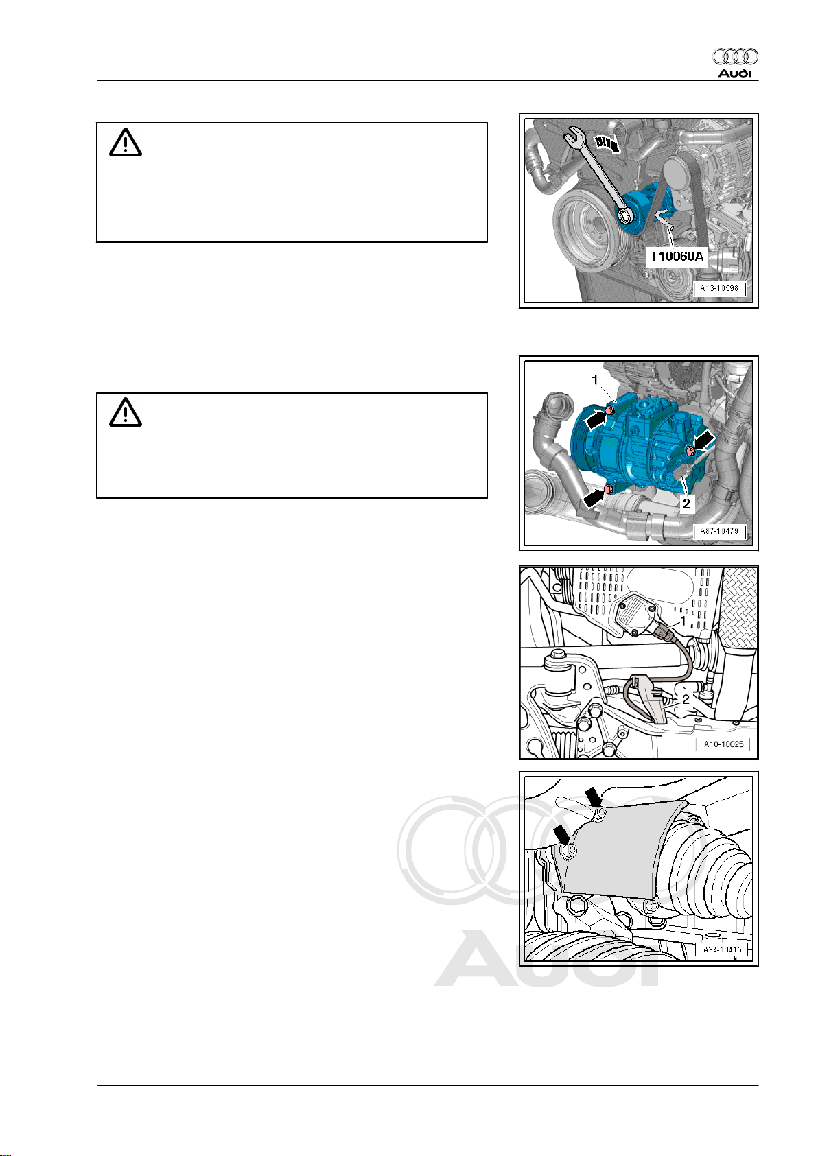
– To slacken poly V-belt turn tensioner in clockwise direction
-arrow-.
– Lock tensioner with locking pin -T10060 A-
– Take off poly V-belt.
– Unplug electrical connector -2- on air conditioner compressor
regulating valve -N280- .
Caution
Make sure that air conditioner compressor and refrigerant
pipes and hoses are not damaged.
Audi TT 2007 ➤
♦ Do NOT stretch, kink or bend refrigerant lines and hoses.
– Remove bolts -arrow-, detach air conditioner compressor -1-
with refrigerant lines connected and tie up to front.
– Unplug electrical connector -1- at oil level and oil temperature
sender -G266- .
– Unclip bracket -2- for wire to oil level and oil temperature
sender -G266- from subframe.
– Remove bolts -arrows- and detach heat shield for drive shaft
(right-side).
– Detach drive shaft (left-side) from flange shaft of gearbox and
tie up.
– Detach drive shaft (right-side) from flange shaft of bevel box.
1. Removing engine 23
Page 30
Protected by copyright. Copying for private or commercial purposes, in part or in whole, is not
permitted unless authorised by AUDI AG. AUDI AG does not guarantee or accept any liability
with respect to the correctness of information in this document. Copyright by AUDI AG.
Audi TT 2007 ➤
4-cylinder TDI engine (2.0 ltr. 4-valve common rail), mechanics - Edition 04.2010
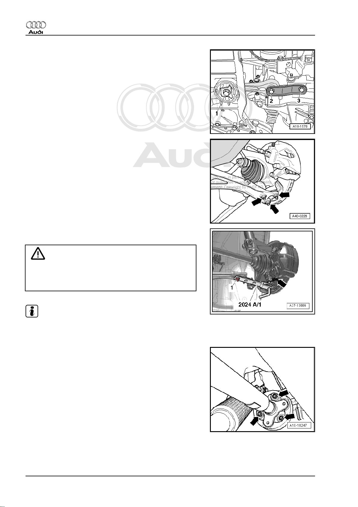
– Remove bolts -1, 2, 3- and remove pendulum support.
– Mark position of nuts -arrows- securing swivel joint.
– Remove nuts for swivel joint (right-side).
– If fitted, remove nut on bracket for front right vehicle level
sender -G289- .
– Detach swivel joint from wishbone.
– Swing suspension strut (right-side) outwards and support with
extension -2024 A /1- as shown in illustration.
WARNING
Accident risk from loose components of support bracket.
♦ Secure retaining pin and swivel joint with locking pin
-arrow- and nut -1-.
Note
The illustration shows the installation position on front suspension
(left-side).
– Mark position of flexible coupling and flange for bevel box in
relation to each other.
– Unbolt flexible coupling for propshaft at bevel box -arrows-
(counterhold using a suitable lever at the triangular flange).
24 Rep. Gr.10 - Removing and installing engine
Page 31

Protected by copyright. Copying for private or commercial purposes, in part or in whole, is not
permitted unless authorised by AUDI AG. AUDI AG does not guarantee or accept any liability
with respect to the correctness of information in this document. Copyright by AUDI AG.
4-cylinder TDI engine (2.0 ltr. 4-valve common rail), mechanics - Edition 04.2010
– Push engine/gearbox assembly forward slightly (towards front
end) and pull propshaft off bevel box.
Caution
Make sure not to damage the seal -arrow- in the propshaft
flange.
♦ Push the propshaft horizontally to the rear and towards the
right side of vehicle as far as possible.
Note
The propshaft must be renewed if oil seal is damaged.
– Unfasten nuts -arrows- for clamp.
Audi TT 2007 ➤
– Remove nuts -1- and -2- and detach bottom bracket for par‐
ticulate filter.
– Tie up particulate filter to rear.
1. Removing engine 25
Page 32

Protected by copyright. Copying for private or commercial purposes, in part or in whole, is not
permitted unless authorised by AUDI AG. AUDI AG does not guarantee or accept any liability
with respect to the correctness of information in this document. Copyright by AUDI AG.
Audi TT 2007 ➤
4-cylinder TDI engine (2.0 ltr. 4-valve common rail), mechanics - Edition 04.2010
– Remove bolts -arrows-.
– Move coolant hose -3- clear.
– Loosen hose clip -2-.
– Unplug electrical connector -1- at charge pressure sender -
G31- and detach air pipe.
– Remove bolt -arrow- and push pump for exhaust gas recircu‐
lation cooler -V400- to the side.
Note
Disregard -items 1, 2, 3-.
– Release fasteners -arrows- and remove noise insulation -1-
for sump.
26 Rep. Gr.10 - Removing and installing engine
Page 33

Protected by copyright. Copying for private or commercial purposes, in part or in whole, is not
permitted unless authorised by AUDI AG. AUDI AG does not guarantee or accept any liability
with respect to the correctness of information in this document. Copyright by AUDI AG.
4-cylinder TDI engine (2.0 ltr. 4-valve common rail), mechanics - Edition 04.2010
– Secure engine bracket -T10012- to cylinder block with bolt
-1- and nut -2- (tightening torque: approx. 20 Nm).
– Insert engine and gearbox jack -V.A.G 1383 A- in engine sup‐
port -T10012- and raise engine/gearbox assembly slightly.
Note
Audi TT 2007 ➤
To unscrew bolts for assembly mounting use stepladder VAS 5085- .
– Remove bolts -arrows- for assembly mounting (engine end).
– Remove bolts -arrows- for assembly mounting (gearbox end).
Note
♦
Check that all hoses, pipes and wiring connections between
engine, gearbox and body have been detached.
♦
Carefully guide engine/gearbox assembly when lowering to
avoid damage.
♦
Make sure there is sufficient clearance at air conditioner com‐
pressor and at left-side drive shaft.
– First lower engine/gearbox assembly only slightly.
– Then swing gearbox end of engine/gearbox assembly for‐
wards and only then lower further.
1. Removing engine 27
Page 34

Protected by copyright. Copying for private or commercial purposes, in part or in whole, is not
permitted unless authorised by AUDI AG. AUDI AG does not guarantee or accept any liability
with respect to the correctness of information in this document. Copyright by AUDI AG.
Audi TT 2007 ➤
4-cylinder TDI engine (2.0 ltr. 4-valve common rail), mechanics - Edition 04.2010
2 Separating engine from manual gear‐
box
Special tools and workshop equipment required
♦ Hooks -10 - 222 A /2-
♦ Workshop hoist -VAS 6100-
♦ Lifting tackle -T40013-
28 Rep. Gr.10 - Removing and installing engine
Page 35

Protected by copyright. Copying for private or commercial purposes, in part or in whole, is not
permitted unless authorised by AUDI AG. AUDI AG does not guarantee or accept any liability
with respect to the correctness of information in this document. Copyright by AUDI AG.
4-cylinder TDI engine (2.0 ltr. 4-valve common rail), mechanics - Edition 04.2010
Procedure
• Engine/gearbox assembly removed and attached to engine
bracket -T10012- .
– Attach lifting tackle -T40013- to gearbox and close lock.
– Attach workshop hoist -VAS 6100- with hooks -10 - 222 A /2-
to the lifting tackle.
– Remove bolts -arrows 2, 3- securing bracket for bevel box.
Audi TT 2007 ➤
Note
Disregard -arrows 1-.
– Remove bolts -1, 3, 4, 5- securing gearbox to engine.
– Detach gearbox from engine.
Note
Disregard -items 2, A-.
2. Separating engine from manual gearbox 29
Page 36

Protected by copyright. Copying for private or commercial purposes, in part or in whole, is not
permitted unless authorised by AUDI AG. AUDI AG does not guarantee or accept any liability
with respect to the correctness of information in this document. Copyright by AUDI AG.
Audi TT 2007 ➤
4-cylinder TDI engine (2.0 ltr. 4-valve common rail), mechanics - Edition 04.2010
3 Securing engine to engine and gearbox support
Special tools and workshop
equipment required
♦ Engine and gearbox sup‐
port -VW 540-
♦ Lifting tackle -3033-
♦ Engine and gearbox sup‐
port -VAS 6095-
♦ Workshop hoist -
VAS 6100-
Procedure
• Gearbox detached from engine ⇒ page 28 .
– Attach lifting tackle -3033- to engine and workshop hoist -
VAS 6100- as shown in illustration.
– Lift engine off engine bracket -T10012- using workshop hoist
-VAS 6100- .
30 Rep. Gr.10 - Removing and installing engine
Page 37

Protected by copyright. Copying for private or commercial purposes, in part or in whole, is not
permitted unless authorised by AUDI AG. AUDI AG does not guarantee or accept any liability
with respect to the correctness of information in this document. Copyright by AUDI AG.
4-cylinder TDI engine (2.0 ltr. 4-valve common rail), mechanics - Edition 04.2010
– Secure engine to engine and gearbox support -VAS 6095- us‐
ing engine and gearbox support -VW 540- .
Audi TT 2007 ➤
3. Securing engine to engine and gearbox support 31
Page 38

Protected by copyright. Copying for private or commercial purposes, in part or in whole, is not
permitted unless authorised by AUDI AG. AUDI AG does not guarantee or accept any liability
with respect to the correctness of information in this document. Copyright by AUDI AG.
Audi TT 2007 ➤
4-cylinder TDI engine (2.0 ltr. 4-valve common rail), mechanics - Edition 04.2010
4 Installing engine
Tightening torques
Note
♦
Tightening torques apply only to lightly greased, oiled,
phosphated or black-finished nuts and bolts.
♦
Additional lubricants such as engine or gearbox oil may be
used, but do not use lubricants containing graphite.
♦
Do not use degreased parts.
♦
Tolerance for tightening torques ± 15 %.
Tightening torques ⇒ page 37
Further tightening torques
Component Nm
Bolts/nuts M6 10
M7 15
M8 20
M10 40
M12 65
32 Rep. Gr.10 - Removing and installing engine
Page 39

Protected by copyright. Copying for private or commercial purposes, in part or in whole, is not
permitted unless authorised by AUDI AG. AUDI AG does not guarantee or accept any liability
with respect to the correctness of information in this document. Copyright by AUDI AG.
4-cylinder TDI engine (2.0 ltr. 4-valve common rail), mechanics - Edition 04.2010
Securing manual gearbox to engine
Audi TT 2007 ➤
Item
2)
1
2)
2
Bolt
1
Nm
M12x55 80
M12x165 80
3 M10x105 40
4 M10x50 40
5
3)
M12x65 80
A Dowel sleeves for centralising
1)
•
Renew bolts.
2)
•
Bolt with M8 threaded pin
3)
•
Screwed into gearbox from engine side
Installation is carried out in the reverse order; note the following:
• Engine/gearbox assembly attached to engine bracket T10012- .
Note
♦
Renew the bolts tightened with specified tightening angle.
♦
Renew self-locking nuts and bolts as well as seals, gaskets
and O-rings.
♦
Hose connections and air pipes and hoses must be free of oil
and grease before assembly.
♦
Secure all hose connections with the correct type of hose clips
(same as original equipment) ⇒ Electronic parts catalogue .
♦
To secure the air hoses at their connections, spray rust re‐
mover onto the worm thread of the used hose clips before
installing.
♦
Fit all cable ties in the original positions when installing.
– If not already fitted, install dowel sleeves for centring engine
and gearbox in cylinder block.
– Ensure that intermediate plate is engaged on sealing flange
and pushed onto dowel sleeves -arrows-.
– Remove needle bearing in crankshaft if fitted ⇒ page 72 .
– Renew clutch release bearing if worn ⇒ Rep. Gr. 30 .
– Lubricate splines of gearbox input shaft lightly with grease for
clutch plate splines ⇒ Electronic parts catalogue .
– Make sure that clutch plate is properly centred.
– Secure gearbox to engine.
– Guide engine/gearbox assembly into body.
4. Installing engine 33
Page 40

Protected by copyright. Copying for private or commercial purposes, in part or in whole, is not
permitted unless authorised by AUDI AG. AUDI AG does not guarantee or accept any liability
with respect to the correctness of information in this document. Copyright by AUDI AG.
Audi TT 2007 ➤
4-cylinder TDI engine (2.0 ltr. 4-valve common rail), mechanics - Edition 04.2010
– Initially hand-tighten bolts -arrows- for assembly mounting
(engine end) as far as stop.
.
34 Rep. Gr.10 - Removing and installing engine
Page 41

Protected by copyright. Copying for private or commercial purposes, in part or in whole, is not
permitted unless authorised by AUDI AG. AUDI AG does not guarantee or accept any liability
with respect to the correctness of information in this document. Copyright by AUDI AG.
4-cylinder TDI engine (2.0 ltr. 4-valve common rail), mechanics - Edition 04.2010
– Initially hand-tighten bolts -arrows- for assembly mounting
(gearbox end) as far as stop.
Note
The bolts are tightened to final torque only after adjusting the as‐
sembly mountings ⇒ page 39 .
– Remove engine support -T10012- from engine.
– Install pump for exhaust gas recirculation cooler -V400-
⇒ page 175 .
– Install air pipe ⇒ page 208 .
– Install particulate filter ⇒ page 218 .
– Secure propshaft with flexible coupling to bevel box flange ⇒
Rear final drive 02D/0AV; Rep. Gr. 39 .
– Install wishbone ⇒ Rep. Gr. 40 .
– Install pendulum support ⇒ Rep. Gr. 34 .
– Install drive shafts ⇒ Rep. Gr. 40 .
– Install air conditioner compressor ⇒ Rep. Gr. 87 .
– Install starter ⇒ Rep. Gr. 27
– Install poly V-belt ⇒ page 44 .
– Install engine control unit ⇒ Rep. Gr. 23 .
– Install radiator ⇒ page 191 .
– Install radiator cowl ⇒ page 192 .
– Connect coolant hoses with plug-in connector to heat ex‐
changer ⇒ page 191 .
– Install air cleaner housing ⇒ Rep. Gr. 23 .
– Install air hose with plug-in connector ⇒ page 209 .
– Connect clutch slave cylinder ⇒ Rep. Gr. 30 .
– Install gear selector cable and gate selector cable ⇒ Rep. Gr.
34 .
– Adjust assembly mountings ⇒ page 39 .
– Electrical connections and routing ⇒ Current flow diagrams,
Electrical fault finding and Fitting locations.
– Observe notes on procedure for connecting the battery ⇒ Rep.
Gr. 27 .
Audi TT 2007 ➤
– Install and adjust wiper arms ⇒ Rep. Gr. 92 .
– Install supplementary fuel pump -V393- ⇒ Rep. Gr. 20 .
– Check oil level ⇒ Maintenance ; Booklet 810 .
Caution
Risk of damage to control units because of excessive voltage.
♦ Never use battery charging equipment for boost starting.
– Fill up with coolant ⇒ page 166 .
4. Installing engine 35
Page 42

Protected by copyright. Copying for private or commercial purposes, in part or in whole, is not
permitted unless authorised by AUDI AG. AUDI AG does not guarantee or accept any liability
with respect to the correctness of information in this document. Copyright by AUDI AG.
Audi TT 2007 ➤
4-cylinder TDI engine (2.0 ltr. 4-valve common rail), mechanics - Edition 04.2010
Note
♦
Do not use drained coolant again if:
♦
the cylinder head or cylinder block have been renewed.
♦
the coolant is contaminated or dirty.
– Install noise insulation frame ⇒ Rep. Gr. 50 .
– Install wheel housing liners (bottom section) and noise insu‐
lation ⇒ Rep. Gr. 66 .
36 Rep. Gr.10 - Removing and installing engine
Page 43

Protected by copyright. Copying for private or commercial purposes, in part or in whole, is not
permitted unless authorised by AUDI AG. AUDI AG does not guarantee or accept any liability
with respect to the correctness of information in this document. Copyright by AUDI AG.
4-cylinder TDI engine (2.0 ltr. 4-valve common rail), mechanics - Edition 04.2010
5 Assembly mountings
5.1 Assembly mountings - exploded view
1 - Bolt
❑ Gearbox support to
gearbox
❑ Tightening torque ⇒
Rep. Gr. 34 ⇒ Rep. Gr.
37
2 - Bolts
❑ Pendulum support to
gearbox
❑ Tightening torque ⇒
Rep. Gr. 34 ⇒ Rep. Gr.
37
3 - Engine support
❑ With support arm
❑ Version fitted in vehicle
may differ from illustra‐
tion
4 - Bolt
❑ Engine support to en‐
gine
❑ Observe correct tighten‐
ing sequence
⇒ page 38
❑ 40 Nm + 180°
5 - Engine mounting
6 - Bolt
❑ Engine mounting to
body
❑ Renew
❑ 40 Nm + 90°
7 - Connecting bracket
8 - Bolt
❑ Connecting bracket to engine mounting
❑ Renew
❑ 20 Nm + 90°
9 - Bolt
❑ Connecting bracket to body
❑ Renew
❑ 20 Nm + 90°
10 - Bolt
❑ Engine mounting to body
❑ Renew
❑ 40 Nm + 90°
11 - Bolts
❑ Engine mounting to engine support
Audi TT 2007 ➤
5. Assembly mountings 37
Page 44

Protected by copyright. Copying for private or commercial purposes, in part or in whole, is not
permitted unless authorised by AUDI AG. AUDI AG does not guarantee or accept any liability
with respect to the correctness of information in this document. Copyright by AUDI AG.
Audi TT 2007 ➤
4-cylinder TDI engine (2.0 ltr. 4-valve common rail), mechanics - Edition 04.2010
❑ Renew
❑ 60 Nm + 90°
12 - Pendulum support
13 - Bolt
❑ Pendulum support to subframe
❑ Tightening torque ⇒ Rep. Gr. 34 ⇒ Rep. Gr. 37
14 - Bolt
❑ Gearbox mounting to gearbox support
❑ Tightening torque ⇒ Rep. Gr. 34 ⇒ Rep. Gr. 37
15 - Bolt
❑ Gearbox mounting to body
❑ Tightening torque ⇒ Rep. Gr. 34 ⇒ Rep. Gr. 37
16 - Gearbox mounting
❑ With support arm
17 - Bolt
❑ Gearbox support to gearbox
❑ Tightening torque ⇒ Rep. Gr. 34 ⇒ Rep. Gr. 37
18 - Gearbox bracket
Tightening sequence for gearbox support
1 - Screw in bolts in the sequence -1, 2, 3- hand-tight.
2 - Tighten bolts in the sequence -1, 2, 3- to 40 Nm.
3 - Turn bolts in the sequence -1, 2, 3- 180° further.
5.2 Checking adjustment of assembly mountings (engine/gearbox mountings)
Procedure
– Remove engine cover panel -arrows-.
38 Rep. Gr.10 - Removing and installing engine
Page 45

Protected by copyright. Copying for private or commercial purposes, in part or in whole, is not
permitted unless authorised by AUDI AG. AUDI AG does not guarantee or accept any liability
with respect to the correctness of information in this document. Copyright by AUDI AG.
4-cylinder TDI engine (2.0 ltr. 4-valve common rail), mechanics - Edition 04.2010
– Disengage fuel hose -3- at bracket.
– Pull off bracket for fuel lines towards right -arrow- and move
clear to one side.
– Unplug electrical connector -1- at supplementary fuel pump -
V393- .
– Remove bolts -2- and -4-, detach bracket with supplementary
fuel pump -V393- and move clear to one side.
– Loosen bolt -1-.
– Remove nut -2- and bolt -3-.
– Detach hose retainer -arrow- from fuel filter and move fuel filter
-8- clear to one side with fuel hoses -4 ... 7- connected.
Audi TT 2007 ➤
The following specifications must be obtained:
• There must be a distance of -a- = 13.5 mm between engine
support -2- and longitudinal member (right-side).
• The side of the engine support casting -2- must be aligned
parallel to the support arm -1- (distance -x- = distance -x-).
Note
Distance -a- = 13.5 mm can also be checked with a metal rod of
suitable size, or similar.
– If the distance measured is too large or small, the assembly
mountings must be adjusted ⇒ page 39 .
Assembling
Installation is carried out in the reverse order; note the following:
– Install fuel filter and supplementary fuel pump -V393- ⇒ Rep.
Gr. 20 .
5.3 Adjusting assembly mountings
Special tools and workshop equipment required
5. Assembly mountings 39
Page 46

Protected by copyright. Copying for private or commercial purposes, in part or in whole, is not
permitted unless authorised by AUDI AG. AUDI AG does not guarantee or accept any liability
with respect to the correctness of information in this document. Copyright by AUDI AG.
Audi TT 2007 ➤
4-cylinder TDI engine (2.0 ltr. 4-valve common rail), mechanics - Edition 04.2010
♦ Support bracket -10 - 222 A-
Procedure
• Tightening torques ⇒ page 37
– Remove engine cover panel -arrows-.
– Disengage fuel hose -3- at bracket.
– Pull off bracket for fuel lines towards right -arrow- and move
clear to one side.
– Unplug electrical connector -1- at supplementary fuel pump -
V393- .
– Remove bolts -2- and -4-, detach bracket with supplementary
fuel pump -V393- and move clear to one side.
– Loosen bolt -1-.
– Remove nut -2- and bolt -3-.
– Detach hose retainer -arrow- from fuel filter and move fuel filter
-8- clear to one side with fuel hoses -4 ... 7- connected.
40 Rep. Gr.10 - Removing and installing engine
Page 47

Protected by copyright. Copying for private or commercial purposes, in part or in whole, is not
permitted unless authorised by AUDI AG. AUDI AG does not guarantee or accept any liability
with respect to the correctness of information in this document. Copyright by AUDI AG.
4-cylinder TDI engine (2.0 ltr. 4-valve common rail), mechanics - Edition 04.2010
– Remove air cleaner housing ⇒ Rep. Gr. 23 .
– Remove bolts -arrows- and detach bracket -1- for air cleaner
housing.
– Position support bracket -10 - 222 A- with spindles -10 - 222
A /11- on bolted flanges of wing panels as shown in illustration.
– Attach hooks of spindles to engine lifting eyes.
– Take up weight of engine/gearbox assembly evenly with both
spindles (do not raise assembly).
Audi TT 2007 ➤
– Remove bolts -arrows- for assembly mounting (engine end)
one by one and renew (if they were not renewed when instal‐
ling engine).
– Initially fit bolts hand-tight.
– Remove bolts -arrows- for assembly mounting (gearbox end)
one by one and renew (if they were not renewed when instal‐
ling engine).
– Initially fit bolts hand-tight.
5. Assembly mountings 41
Page 48

Protected by copyright. Copying for private or commercial purposes, in part or in whole, is not
permitted unless authorised by AUDI AG. AUDI AG does not guarantee or accept any liability
with respect to the correctness of information in this document. Copyright by AUDI AG.
Audi TT 2007 ➤
4-cylinder TDI engine (2.0 ltr. 4-valve common rail), mechanics - Edition 04.2010
– Using assembly lever, adjust engine/gearbox assembly be‐
tween engine mounting and support arm -1- until specifica‐
tions listed below are attained:
• There must be a distance of -a- = 13.5 mm between engine
support -2- and longitudinal member (right-side).
• The side of the engine support casting -2- must be aligned
parallel to the support arm -1- (distance -x- = distance -x-).
Note
Distance -a- = 13.5 mm can also be checked with a metal rod of
suitable size, or similar.
– Tighten bolts for assembly mounting (engine end).
– Ensure that the edges of the support arm (on the gearbox as‐
sembly mounting) -1- and gearbox mounting -2- are parallel.
• Dimension -x- = dimension -x-.
– Tighten bolts for assembly mounting (gearbox end).
Installation is carried out in the reverse order; note the following:
– Install air cleaner housing ⇒ Rep. Gr. 23 .
– Install fuel filter and supplementary fuel pump -V393- ⇒ Rep.
Gr. 20 .
42 Rep. Gr.10 - Removing and installing engine
Page 49

Protected by copyright. Copying for private or commercial purposes, in part or in whole, is not
permitted unless authorised by AUDI AG. AUDI AG does not guarantee or accept any liability
with respect to the correctness of information in this document. Copyright by AUDI AG.
Audi TT 2007 ➤
4-cylinder TDI engine (2.0 ltr. 4-valve common rail), mechanics - Edition 04.2010
13 – Crankshaft group
1 Cylinder block (pulley end)
1.1 Poly V-belt drive with tensioner and air conditioner compressor - exploded view
1 - Poly V-belt
❑ Check for wear
❑ Before removing, mark
direction of rotation with
chalk or felt-tip pen
❑ Removing and installing
⇒ page 44
❑ Do not kink
❑ When installing, make
sure it is properly seated
on pulleys.
2 - Poly V-belt tensioner
❑ Removing and installing
⇒ page 47
3 - Vibration damper
❑ With poly V-belt pulley
❑ Installation position:
hole in vibration damper
must be positioned over
raised section of crank‐
shaft sprocket
❑ Removing and installing
⇒ page 49
4 - Bolt
❑ Renew
❑ Use only genuine bolts
⇒ Electronic parts cata‐
logue
❑ 10 Nm + 90°
5 - Bolt
❑ Tightening torque ⇒
Rep. Gr. 27
6 - Dowel sleeve
❑ Ensure correct seating in bracket for ancillaries
7 - Bolt
❑ Tightening torque ⇒ Rep. Gr. 23
8 - Bolt
❑ Tightening torque ⇒ Item 20 (page 85)
9 - Idler roller
❑ For toothed belt
10 - Bolt
❑ Tightening torque ⇒ Item 6 (page 84)
1. Cylinder block (pulley end) 43
Page 50

Protected by copyright. Copying for private or commercial purposes, in part or in whole, is not
permitted unless authorised by AUDI AG. AUDI AG does not guarantee or accept any liability
with respect to the correctness of information in this document. Copyright by AUDI AG.
Audi TT 2007 ➤
4-cylinder TDI engine (2.0 ltr. 4-valve common rail), mechanics - Edition 04.2010
11 - Idler roller
❑ For toothed belt
12 - Bracket for ancillaries
❑ Removing and installing ⇒ page 50
13 - High-pressure pump
❑ Removing and installing ⇒ Rep. Gr. 23
14 - Bolt
❑ 23 Nm
15 - Bolt
❑ Tightening torque and sequence ⇒ page 44
16 - Alternator
❑ Removing and installing ⇒ Rep. Gr. 27
17 - Bolt
❑ Tightening torque ⇒ Rep. Gr. 27
18 - Air conditioner compressor
❑ Removing and installing ⇒ Rep. Gr. 87
19 - Bolt
❑ Tightening torque ⇒ Rep. Gr. 87
20 - Dowel sleeve
❑ Ensure correct seating in bracket for ancillaries
Bracket for ancillaries - tightening torque and tightening sequence
– Renew bolts for bracket for ancillaries and fit as follows:
♦ Bolts -1- and -2- M10x52.
♦ Bolts -3- and -6- M10x30.
♦ Bolts -4- and -5- M10x60.
– Tighten bolts for bracket for ancillaries in the sequence
-1 ... 6- in 4 stages as follows:
1. Screw in all bolts by hand until they make contact.
2. Tighten all bolts to 40 Nm.
3. Turn bolts -3- and -6- 45° further.
4. Turn bolts -1, 2, 4, 5- 90° further.
1.2 Removing and installing poly V-belt - ve‐
hicles with tensioner and air conditioner
compressor
Special tools and workshop equipment required
44 Rep. Gr.13 - Crankshaft group
Page 51

Protected by copyright. Copying for private or commercial purposes, in part or in whole, is not
permitted unless authorised by AUDI AG. AUDI AG does not guarantee or accept any liability
with respect to the correctness of information in this document. Copyright by AUDI AG.
4-cylinder TDI engine (2.0 ltr. 4-valve common rail), mechanics - Edition 04.2010
♦ Locking pin -T10060 A-
Removing
– Release fasteners -1 ... 4- and remove centre noise insulation.
Audi TT 2007 ➤
– Release fasteners -arrows- and remove right wheel housing
liner (bottom section).
1. Cylinder block (pulley end) 45
Page 52

Protected by copyright. Copying for private or commercial purposes, in part or in whole, is not
permitted unless authorised by AUDI AG. AUDI AG does not guarantee or accept any liability
with respect to the correctness of information in this document. Copyright by AUDI AG.
Audi TT 2007 ➤
4-cylinder TDI engine (2.0 ltr. 4-valve common rail), mechanics - Edition 04.2010
Caution
If a used belt runs in the opposite direction when it is refitted,
this can cause breakage.
♦ Before removing, mark direction of rotation of poly V-belt
with chalk or felt-tipped pen for re-installation.
– To slacken poly V-belt turn tensioner in clockwise direction
-arrow-.
– Lock tensioner with locking pin -T10060 A-
– Take off poly V-belt.
Installing
Installation is carried out in the reverse order; note the following:
Note
Before fitting poly V-belt, make sure all mechanical units (e.g. al‐
ternator and air conditioner compressor) are firmly in position.
– Fit poly V-belt on all poly V-belt pulleys:
1 - Crankshaft
2 - Tensioner
3 - Alternator
4 - Air conditioner compressor
– Hold tensioner with ring spanner and remove locking pin -
T10060 A- .
– Slacken tensioner.
– Check that poly V-belt is properly seated.
– Start engine and check that belt runs properly.
– Install right wheel housing liner (bottom section) and noise in‐
sulation ⇒ Rep. Gr. 66 .
46 Rep. Gr.13 - Crankshaft group
Page 53

Protected by copyright. Copying for private or commercial purposes, in part or in whole, is not
permitted unless authorised by AUDI AG. AUDI AG does not guarantee or accept any liability
with respect to the correctness of information in this document. Copyright by AUDI AG.
4-cylinder TDI engine (2.0 ltr. 4-valve common rail), mechanics - Edition 04.2010
1.3 Removing and installing tensioner for poly V-belt
Removing
– Detach poly V-belt from tensioner
⇒ “1.2 Removing and installing poly V-belt - vehicles with ten‐
sioner and air conditioner compressor”, page 44 .
– Release hose clip -2-, lift retaining clip -1- slightly and remove
air hose.
– Remove bolts -arrows-.
– Move coolant hose -3- clear.
– Loosen hose clip -2-.
– Unplug electrical connector -1- at charge pressure sender -
G31- and detach air pipe.
Audi TT 2007 ➤
– Remove bolt -2- and take off tensioner -1- for poly-V-belt.
Installing
• Tightening torque ⇒ page 43 .
Installation is carried out in the reverse order; note the following:
– Install air pipe ⇒ page 208 .
– Install air hose with plug-in connector ⇒ page 209 .
– Install poly V-belt ⇒ page 44 .
1. Cylinder block (pulley end) 47
Page 54

Protected by copyright. Copying for private or commercial purposes, in part or in whole, is not
permitted unless authorised by AUDI AG. AUDI AG does not guarantee or accept any liability
with respect to the correctness of information in this document. Copyright by AUDI AG.
Audi TT 2007 ➤
4-cylinder TDI engine (2.0 ltr. 4-valve common rail), mechanics - Edition 04.2010
1.4 Poly V-belt drive without air conditioner compressor - exploded view
1 - Vibration damper
❑ With poly V-belt pulley
❑ Installation position:
hole in vibration damper
must be positioned over
raised section of crank‐
shaft sprocket
❑ Removing and installing
⇒ page 49
2 - Bolt
❑ Tightening torque ⇒
Electrical system; Rep.
Gr. 27
3 - Alternator
❑ Removing and installing
⇒ Electrical system;
Rep. Gr. 27
4 - Bracket for ancillaries
❑ Removing and installing
⇒ page 50
5 - Poly V-belt
❑ Renew.
❑ Removing and installing
⇒ page 48
1.5 Removing and installing poly V-belt - ve‐
hicles without air conditioner compres‐
sor
Note
The poly V-belt tensioner is not installed on vehicles without air
conditioner (equipment version).
Special tools and workshop equipment required
♦ Poly V-belt repair set with assembly tool ⇒ Electronic parts
catalogue
48 Rep. Gr.13 - Crankshaft group
Page 55

Protected by copyright. Copying for private or commercial purposes, in part or in whole, is not
permitted unless authorised by AUDI AG. AUDI AG does not guarantee or accept any liability
with respect to the correctness of information in this document. Copyright by AUDI AG.
4-cylinder TDI engine (2.0 ltr. 4-valve common rail), mechanics - Edition 04.2010
Procedure
– Release fasteners -1 ... 4- and remove centre noise insulation.
Note
The poly V-belt repair set with assembly tool contains the assem‐
bly tool -T10367- and illustrated instructions.
– Remove front right wheel.
– Release fasteners -arrows- and remove right wheel housing
liner (bottom section).
– Follow procedure specified in illustrated instructions.
Installation is carried out in the reverse order; note the following:
– Install front section of wheel housing liner (front section) ⇒
Rep. Gr. 66 .
– Install noise insulation ⇒ Rep. Gr. 50 .
– Install front wheel ⇒ Rep. Gr. 44 .
Audi TT 2007 ➤
1.6 Removing and installing vibration damp‐
er
Removing
– Removing poly V-belt
♦ ⇒ “1.2 Removing and installing poly V-belt - vehicles with ten‐
sioner and air conditioner compressor”, page 44
♦ ⇒ “1.5 Removing and installing poly V-belt - vehicles without
air conditioner compressor”, page 48
– Counterhold by applying ring spanner to bolt for crankshaft
sprocket and slacken bolts for vibration damper.
– Remove bolts and take off vibration damper.
1. Cylinder block (pulley end) 49
Page 56

Protected by copyright. Copying for private or commercial purposes, in part or in whole, is not
permitted unless authorised by AUDI AG. AUDI AG does not guarantee or accept any liability
with respect to the correctness of information in this document. Copyright by AUDI AG.
Audi TT 2007 ➤
4-cylinder TDI engine (2.0 ltr. 4-valve common rail), mechanics - Edition 04.2010
Installing
• Tightening torque ⇒ page 43 .
• Tightening torque
⇒ “1.1 Poly V-belt drive with tensioner and air conditioner
compressor - exploded view”, page 43 .
• Tightening torque
⇒ “1.4 Poly V-belt drive without air conditioner compressor exploded view”, page 48 .
Installation is carried out in the reverse order; note the following:
Note
Renew bolts for vibration damper.
• Installation position: hole -arrow- in vibration damper must be
positioned over raised section of crankshaft sprocket.
– Install poly V-belt.
♦ ⇒ “1.2 Removing and installing poly V-belt - vehicles with ten‐
sioner and air conditioner compressor”, page 44
♦ ⇒ “1.5 Removing and installing poly V-belt - vehicles without
air conditioner compressor”, page 48
1.7 Removing and installing bracket for an‐
cillaries
Special tools and workshop equipment required
♦ Support bracket -10 - 222 A-
♦ Eye-head bolt -3368-
50 Rep. Gr.13 - Crankshaft group
Page 57

Protected by copyright. Copying for private or commercial purposes, in part or in whole, is not
permitted unless authorised by AUDI AG. AUDI AG does not guarantee or accept any liability
with respect to the correctness of information in this document. Copyright by AUDI AG.
4-cylinder TDI engine (2.0 ltr. 4-valve common rail), mechanics - Edition 04.2010
♦ Engine support bracket (supplementary set) -T40093-
♦ Flange nut M10 or nut M10 with washer
Removing
– Remove alternator ⇒ Rep. Gr. 27 .
– Remove high-pressure pump ⇒ Rep. Gr. 23 .
– Position support bracket -10 - 222 A- with adapters and spin‐
dles on bolted flanges of wing panels as shown in illustration.
– Attach hook of spindle to engine lifting eye (left-side).
Audi TT 2007 ➤
WARNING
Risk of accident because of loose bolt connections.
♦ Screw on flange nut or nut with washer -arrow- at least 6
turns to ensure that eye-head bolt -3368- is properly se‐
cured.
– Secure eye-head bolt -3368- with flange nut M10 or nut with
washer to engine support as shown in illustration.
– Attach spindle -10 - 222 A /11- (right-side) to eye-head bolt
-3368- .
– Take up weight of engine evenly with both spindles (but do not
raise engine).
1. Cylinder block (pulley end) 51
Page 58

Protected by copyright. Copying for private or commercial purposes, in part or in whole, is not
permitted unless authorised by AUDI AG. AUDI AG does not guarantee or accept any liability
with respect to the correctness of information in this document. Copyright by AUDI AG.
Audi TT 2007 ➤
4-cylinder TDI engine (2.0 ltr. 4-valve common rail), mechanics - Edition 04.2010
– Remove bolts -arrows-.
– Detach electrical connector at coolant shortage indicator
switch -F66- and move coolant expansion tank to side.
– Remove bolts -1- and -2- and remove connecting bracket.
– Remove bolts -3 ... 6- and detach engine mounting.
– Remove bolt -3- on engine support.
Note
Disregard -items 1, 2-.
– Remove bolt -arrow-.
– Remove bolts -1- and -2- and remove idler rollers for toothed
belt.
52 Rep. Gr.13 - Crankshaft group
Page 59

Protected by copyright. Copying for private or commercial purposes, in part or in whole, is not
permitted unless authorised by AUDI AG. AUDI AG does not guarantee or accept any liability
with respect to the correctness of information in this document. Copyright by AUDI AG.
4-cylinder TDI engine (2.0 ltr. 4-valve common rail), mechanics - Edition 04.2010
– Remove bolts -1 ... 6- and detach bracket for ancillaries.
Installing
Installation is carried out in the reverse order; note the following:
Note
Renew bolts securing bracket for ancillaries.
– Check that dowel sleeve at top right between bracket for an‐
cillaries and cylinder block is fitted; insert dowel sleeve if
necessary.
– Tighten bolts for bracket for ancillaries ⇒ page 44 .
– Install engine support and engine mounting ⇒ page 37 .
– Install high-pressure pump ⇒ Rep. Gr. 23 .
– Install toothed belt (adjust valve timing) ⇒ page 91 .
– Install alternator ⇒ Rep. Gr. 27 .
Audi TT 2007 ➤
1.8 Sealing flange (pulley end) - exploded view
1 - Bolt
❑ Tightening torque
⇒ Item 25 (page 85)
2 - Crankshaft sprocket
❑ Contact surface be‐
tween sprocket and
crankshaft must be free
of oil
❑ Can only be installed in
one position
3 - Oil seal for crankshaft (pul‐
ley end)
❑ Renewing ⇒ page 54
❑ Do not lubricate with oil
4 - Sealing flange (pulley end)
❑ Should be positioned on
dowel pins
❑ Removing and installing
⇒ page 56
5 - Cylinder block
6 - Dowel pin
❑ 2x
7 - Bolt
❑ Tightening torque and
sequence ⇒ page 54
1. Cylinder block (pulley end) 53
Page 60

Protected by copyright. Copying for private or commercial purposes, in part or in whole, is not
permitted unless authorised by AUDI AG. AUDI AG does not guarantee or accept any liability
with respect to the correctness of information in this document. Copyright by AUDI AG.
Audi TT 2007 ➤
4-cylinder TDI engine (2.0 ltr. 4-valve common rail), mechanics - Edition 04.2010
Sealing flange (pulley end) - tightening torque and sequence
– Tighten bolts for sealing flange on pulley end -1 ... 10- in three
stages as follows:
1. Screw in bolts -1 ... 10- by hand until they make contact.
2. Tighten bolts -1 ... 6- in diagonal sequence and in stages
to 15 Nm.
3. Tighten bolts -7 ... 10- to 15 Nm.
1.9 Renewing crankshaft oil seal (pulley end)
Special tools and workshop equipment required
♦ Oil seal extractor -3203-
♦ Counterhold tool -3415-
♦ Assembly tool -T10053-
54 Rep. Gr.13 - Crankshaft group
Page 61

Protected by copyright. Copying for private or commercial purposes, in part or in whole, is not
permitted unless authorised by AUDI AG. AUDI AG does not guarantee or accept any liability
with respect to the correctness of information in this document. Copyright by AUDI AG.
4-cylinder TDI engine (2.0 ltr. 4-valve common rail), mechanics - Edition 04.2010
Procedure
– Remove toothed belt ⇒ page 86 .
– Loosen bolt for crankshaft sprocket using counterhold tool
-3415- .
– Remove bolt and detach crankshaft sprocket.
– Adjust inner section of oil seal extractor -3203- so it is flush
with the outer section and lock in position with knurled screw.
– Lubricate threaded head of oil seal extractor, place it in posi‐
tion and screw it into oil seal as far as possible (applying firm
pressure).
– Loosen knurled screw and turn inner part against crankshaft
until the oil seal is pulled out.
– Clamp flats of oil seal extractor in vice and use pliers to remove
oil seal.
– Clean contact surface and sealing surface for oil seal.
– Remove oil residue from crankshaft journal with a clean cloth.
Audi TT 2007 ➤
Note
Do not lubricate sealing lip and outer rim of oil seal before press‐
ing in.
– Fit guide sleeve -T10053/1- onto crankshaft journal.
– Push oil seal over guide sleeve onto crankshaft journal.
– Press in oil seal using bolt for crankshaft sprocket and thrust
sleeve of assembly tool -T10053- until flush.
– Install crankshaft sprocket ⇒ page 84 .
– Install toothed belt (adjust valve timing) ⇒ page 91 .
1. Cylinder block (pulley end) 55
Page 62

Protected by copyright. Copying for private or commercial purposes, in part or in whole, is not
permitted unless authorised by AUDI AG. AUDI AG does not guarantee or accept any liability
with respect to the correctness of information in this document. Copyright by AUDI AG.
Audi TT 2007 ➤
4-cylinder TDI engine (2.0 ltr. 4-valve common rail), mechanics - Edition 04.2010
1.10 Removing and installing sealing flange (pulley end)
Special tools and workshop equipment required
♦ Counterhold tool -3415-
♦ Electric drill with plastic brush attachment
♦ Safety goggles
♦ Sealant ⇒ Electronic parts catalogue
Removing
– Remove toothed belt ⇒ page 86 .
– Loosen bolt for crankshaft sprocket using counterhold tool
-3415- .
– Remove bolt and detach crankshaft sprocket.
– Remove bolts -1 ... 10- and carefully release sealing flange
from bonded joint.
– Drive out oil seal with sealing flange removed.
Installing
• Tightening torque ⇒ page 53 .
Installation is carried out in the reverse order; note the following:
Caution
Make sure sealant residue does not enter lubrication system.
♦ Place a clean cloth over the exposed section of the sump.
– Carefully remove sealant residue on cylinder block and sump.
56 Rep. Gr.13 - Crankshaft group
Page 63

Protected by copyright. Copying for private or commercial purposes, in part or in whole, is not
permitted unless authorised by AUDI AG. AUDI AG does not guarantee or accept any liability
with respect to the correctness of information in this document. Copyright by AUDI AG.
4-cylinder TDI engine (2.0 ltr. 4-valve common rail), mechanics - Edition 04.2010
WARNING
Protect eyes against injuries.
♦ Wear safety goggles.
– Use e.g. rotating plastic brush to remove sealant residue on
sealing flange.
– Clean sealing surfaces; they must be free of oil and grease.
Note
Note the use-by date of the sealant.
– Cut off nozzle of tube at front marking (nozzle ∅ approx. 2
mm).
Audi TT 2007 ➤
– Apply a thin bead of sealant at the edge of the joint between
the cylinder block and the sump -arrows-.
Caution
Make sure lubrication system is not clogged by excess sealant.
♦ The bead of sealant must not be thicker than specified.
– Apply bead of sealant -arrow- onto clean sealing surface of
sealing flange as shown in illustration.
• Thickness of sealant bead: 2 ... 3 mm
1. Cylinder block (pulley end) 57
Page 64

Protected by copyright. Copying for private or commercial purposes, in part or in whole, is not
permitted unless authorised by AUDI AG. AUDI AG does not guarantee or accept any liability
with respect to the correctness of information in this document. Copyright by AUDI AG.
Audi TT 2007 ➤
4-cylinder TDI engine (2.0 ltr. 4-valve common rail), mechanics - Edition 04.2010
– Apply a thin coat of sealant to bottom sealing surface
-shaded- on sealing flange.
Note
The sealing flange must be installed within 5 minutes after apply‐
ing the sealant.
– Carefully fit sealing flange onto dowel pins in cylinder block.
– Tighten sealing flange bolts ⇒ page 54 .
– Install crankshaft oil seal (pulley end) ⇒ page 54 .
58 Rep. Gr.13 - Crankshaft group
Page 65

Protected by copyright. Copying for private or commercial purposes, in part or in whole, is not
permitted unless authorised by AUDI AG. AUDI AG does not guarantee or accept any liability
with respect to the correctness of information in this document. Copyright by AUDI AG.
Audi TT 2007 ➤
4-cylinder TDI engine (2.0 ltr. 4-valve common rail), mechanics - Edition 04.2010
2 Cylinder block (gearbox end)
Note
Servicing clutch ⇒ Rep. Gr. 30
2.1 Dual-mass flywheel and sealing flange (gearbox end) - exploded view
1 - Bolt
❑ Renew
❑ 60 Nm + 90°
2 - Dual-mass flywheel
❑ Removing and installing
⇒ page 60
❑ Can only be installed in
one position
3 - Sender wheel
❑ For engine speed send‐
er -G28-
❑ Removing and installing
⇒ “2.3 Renewing seal‐
ing flange (gearbox
end)”, page 61
4 - Engine speed sender -G28-
❑ Removing and installing
⇒ “2.3 Renewing seal‐
ing flange (gearbox
end)”, page 61
5 - Bolt
❑ 4.5 Nm
6 - Dowel pin
❑ 2x
7 - Intermediate plate
❑ Should be positioned on
dowel pins
❑ Do not damage or bend
when assembling
❑ Engaging on sealing
flange ⇒ page 60
8 - Sealing flange (gearbox
end)
❑ With oil seal
❑ Renewing ⇒ page 61
9 - Bolt
❑ Tightening torque and sequence ⇒ page 60
2. Cylinder block (gearbox end) 59
Page 66

Protected by copyright. Copying for private or commercial purposes, in part or in whole, is not
permitted unless authorised by AUDI AG. AUDI AG does not guarantee or accept any liability
with respect to the correctness of information in this document. Copyright by AUDI AG.
Audi TT 2007 ➤
4-cylinder TDI engine (2.0 ltr. 4-valve common rail), mechanics - Edition 04.2010
Installing intermediate plate
– Engage intermediate plate on sealing flange -top arrow- and
push onto dowel sleeves -bottom arrows-.
Sealing flange (gearbox end) - tightening torque and sequence
– Renew sealing flange bolts (gearbox end).
– Tighten bolts -1 … 6- in 2 stages as follows:
1. Screw in bolts by hand until they make contact.
2. Tighten in stages and in diagonal sequence; final torque 15
Nm.
2.2 Removing and installing dual-mass fly‐
wheel
Special tools and workshop equipment required
♦ Counterhold tool -3067-
Removing
• Gearbox removed.
Caution
Make sure dual-mass flywheel is not damaged.
♦ Remove bolts -B- using normal hand tools (do not use
pneumatic wrench or impact driver, etc.).
♦ When removing the bolts, make sure that the bolt heads
do not come into contact with the dual-mass flywheel.
♦ Rotate the dual-mass flywheel -A- so that the bolts -B-
align centrally with the holes -arrows-.
60 Rep. Gr.13 - Crankshaft group
Page 67

Protected by copyright. Copying for private or commercial purposes, in part or in whole, is not
permitted unless authorised by AUDI AG. AUDI AG does not guarantee or accept any liability
with respect to the correctness of information in this document. Copyright by AUDI AG.
4-cylinder TDI engine (2.0 ltr. 4-valve common rail), mechanics - Edition 04.2010
– Insert counterhold tool -3067- in hole on cylinder block
-item B-, slacken bolts for dual-mass flywheel.
– Remove bolts and take off dual-mass flywheel.
Installing
• Tightening torque ⇒ page 59 .
Installation is carried out in the reverse order; note the following:
Note
Renew bolts for dual-mass flywheel.
– Insert counterhold -3067- in hole on cylinder block -item A-.
2.3 Renewing sealing flange (gearbox end)
Audi TT 2007 ➤
Special tools and workshop equipment required
♦ Tool insert, AF 24 -V.A.G 1332/11-
♦ Assembly tool -T10134-
2. Cylinder block (gearbox end) 61
Page 68

Protected by copyright. Copying for private or commercial purposes, in part or in whole, is not
permitted unless authorised by AUDI AG. AUDI AG does not guarantee or accept any liability
with respect to the correctness of information in this document. Copyright by AUDI AG.
Audi TT 2007 ➤
4-cylinder TDI engine (2.0 ltr. 4-valve common rail), mechanics - Edition 04.2010
♦ Depth gauge -VAS 6082-
♦ Hexagon screwdriver insert with ball head 4 mm for hexagon
socket head bolts (commercially available)
♦ 3x M6x35 bolt
♦ 2x M7x35 bolt
Pressing out sealing flange with sender wheel
• Gearbox removed.
– Remove dual-mass flywheel ⇒ page 60 .
– Detach intermediate plate from sealing flange and dowel pins
-arrows-.
– Rotate crankshaft by turning bolt for toothed belt sprocket until
crankshaft is positioned at “TDC”, as shown in illustration.
– Remove sump ⇒ page 139 .
Note
For illustration purposes, the following procedure is shown with
the engine removed.
– Use hexagon screwdriver insert with ball head 4 mm for hex‐
agon socket head bolts to remove engine speed sender -G28-
-item 1-.
Note
Disregard -item 2-.
62 Rep. Gr.13 - Crankshaft group
Page 69

Protected by copyright. Copying for private or commercial purposes, in part or in whole, is not
permitted unless authorised by AUDI AG. AUDI AG does not guarantee or accept any liability
with respect to the correctness of information in this document. Copyright by AUDI AG.
4-cylinder TDI engine (2.0 ltr. 4-valve common rail), mechanics - Edition 04.2010
– Remove bolts -1 ... 6- for sealing flange.
Note
The sealing flange is pressed off the crankshaft together with the
sender wheel.
– To press off, screw 3 bolts M6x35 -arrows- alternately into
sealing flange not more than 1/2 turn at a time.
Audi TT 2007 ➤
– Take off sealing flange with sender wheel.
Pressing in sealing flange with sender wheel
Note
♦
The sealing flange with PTFE oil seal is fitted with a sealing lip
support ring. This support ring acts as an assembly sleeve and
must not be removed before installation.
♦
Sealing flange and sender wheel must not be separated or
rotated out of position after removal from packaging.
♦
The sender wheel is held in its installation position by a locat‐
ing pin on the assembly tool -T10134- .
♦
The sealing flange and oil seal are one unit and must always
be replaced together with the sender wheel.
♦
The assembly tool -T10134- is held in the correct position rel‐
ative to the crankshaft by a guide pin which is inserted into a
hole in the crankshaft.
Construction of assembly tool -T10134-
A - Tightening flats
B - Hexagon nut
C - Assembly housing
D - Locating pin
E - Hexagon socket-head bolt
F - Guide pin for diesel engines (black handle)
G - Guide pin for petrol engines (red handle)
2. Cylinder block (gearbox end) 63
Page 70

Protected by copyright. Copying for private or commercial purposes, in part or in whole, is not
permitted unless authorised by AUDI AG. AUDI AG does not guarantee or accept any liability
with respect to the correctness of information in this document. Copyright by AUDI AG.
Audi TT 2007 ➤
4-cylinder TDI engine (2.0 ltr. 4-valve common rail), mechanics - Edition 04.2010
A - Fitting sealing flange with sender wheel onto assembly tool T10134- :
– Turn hexagon nut -B- on threaded spindle until it is just in front
of flats -A-.
– Clamp assembly tool -T10134- in a vice on tightening flats
-A- of threaded spindle.
– Press assembly housing -C- downwards so that it lies on hex‐
agon nut -arrow-.
• Inner part of assembly device and assembly housing must
align (be level) with each other.
– Remove the securing clip -arrow- from new sealing flange.
Note
The sender wheel must not be taken out of the sealing flange or
rotated out of position.
• The locating hole -A- on the sender wheel -C- must align with
the marking -B- on the sealing flange.
– Place the sealing flange (with the front side downwards) on a
clean flat surface.
64 Rep. Gr.13 - Crankshaft group
Page 71

Protected by copyright. Copying for private or commercial purposes, in part or in whole, is not
permitted unless authorised by AUDI AG. AUDI AG does not guarantee or accept any liability
with respect to the correctness of information in this document. Copyright by AUDI AG.
4-cylinder TDI engine (2.0 ltr. 4-valve common rail), mechanics - Edition 04.2010
– Press the sealing lip support ring -A- downwards in direction
of -arrows- until it lies against the flat surface.
• The upper edge of the sender wheel and the front edge of the
sealing flange must align -arrows-.
Audi TT 2007 ➤
– Place front side of sealing flange on assembly tool -T10134- ,
so that locating pin -B- can be inserted in hole -A- in sender
wheel.
• Ensure the sealing flange lies flat on the assembly tool.
– Press the sealing flange and sealing lip support ring -B- onto
the surface of the assembly tool -T10134- while tightening the
3 knurled screws -A- so that the locating pin will not slip out of
the hole in the sender wheel.
• Ensure that the sender wheel remains fixed on the assembly
tool when installing the sealing flange.
2. Cylinder block (gearbox end) 65
Page 72

Protected by copyright. Copying for private or commercial purposes, in part or in whole, is not
permitted unless authorised by AUDI AG. AUDI AG does not guarantee or accept any liability
with respect to the correctness of information in this document. Copyright by AUDI AG.
Audi TT 2007 ➤
4-cylinder TDI engine (2.0 ltr. 4-valve common rail), mechanics - Edition 04.2010
B - Installing assembly tool -T10134- with sealing flange on crank‐
shaft flange:
• Crankshaft flange must be free of oil or grease.
• Engine is at “TDC” position.
– Screw hexagon nut -B- to end of threaded spindle.
– Press the threaded spindle of assembly tool -T10134- in di‐
rection of -arrow- until the hexagon nut -B- lies on the assem‐
bly housing -A-.
– Position flat edge of assembly housing towards sealing sur‐
face for sump on cylinder block.
– Secure assembly tool -T10134- to crankshaft flange by screw‐
ing hexagon socket head bolts -A- approx. 5 threads into
crankshaft flange.
– Screw two bolts M7×35 mm -item A- into cylinder block to
guide sealing flange.
C - Securing assembly tool -T10134- onto crankshaft flange:
– Press the assembly housing -C- by hand in the direction of the
-arrow- until the sealing lip support ring -B- lies on the surface
of the crankshaft flange -A-.
Caution
Do not interchange components.
♦ The guide pin for PETROL engines (red handle) -F- MUST
NOT be inserted into the threaded hole in the crankshaft.
– Push guide pin for diesel engine (black handle) -D- into hole
in crankshaft. This brings the sender wheel into its final instal‐
lation position.
– Tighten the two hexagon socket head bolts on assembly tool
hand-tight.
– Screw hexagon nut -E- onto threaded spindle by hand until it
lies against the assembly housing -C-.
66 Rep. Gr.13 - Crankshaft group
Page 73

Protected by copyright. Copying for private or commercial purposes, in part or in whole, is not
permitted unless authorised by AUDI AG. AUDI AG does not guarantee or accept any liability
with respect to the correctness of information in this document. Copyright by AUDI AG.
4-cylinder TDI engine (2.0 ltr. 4-valve common rail), mechanics - Edition 04.2010
D - Pressing sender wheel onto crankshaft flange with assembly
tool -T10134- :
– Tighten hexagon nut on assembly tool -T10134- to 35 Nm.
• A small air gap must be present between cylinder block and
sealing flange after tightening hexagon nut to 35 Nm.
E - Checking installation position of sender wheel on crankshaft:
– Screw hexagon nut -E- to end of threaded spindle.
– Remove bolts -A- from cylinder block.
– Unscrew knurled screws -B- from sealing flange.
– Detach assembly tool -T10134- .
– Detach sealing lip support ring.
Audi TT 2007 ➤
– Apply depth gauge -VAS 6082- to crankshaft flange.
– Measure distance between crankshaft flange -A- and sender
wheel -B-.
• Specification: Distance -a- = 0.5 mm.
– Press sender wheel in further if distance -a- is too small
⇒ page 68 .
– If reading matches specification, continue with assembly
⇒ page 68 .
2. Cylinder block (gearbox end) 67
Page 74

Protected by copyright. Copying for private or commercial purposes, in part or in whole, is not
permitted unless authorised by AUDI AG. AUDI AG does not guarantee or accept any liability
with respect to the correctness of information in this document. Copyright by AUDI AG.
Audi TT 2007 ➤
4-cylinder TDI engine (2.0 ltr. 4-valve common rail), mechanics - Edition 04.2010
F - Pressing sender wheel in further:
– Secure assembly tool -T10134- -item A- to crankshaft flange
by tightening hexagon socket head bolts hand-tight.
– Press assembly tool onto sealing flange by hand.
– Screw hexagon nut -E- onto threaded spindle by hand until it
lies against the assembly housing -C-.
– Tighten hexagon nut on assembly tool -T10134- to 40 Nm.
– Check installation position of sender wheel on crankshaft
again ⇒ page 67 .
– If distance “a” is still to small, tighten hexagon nut on assembly
tool -T10134- to 45 Nm.
– Check installation position of sender wheel on crankshaft
again ⇒ page 67 .
Assembling:
– Tighten sealing flange bolts ⇒ page 60 .
68 Rep. Gr.13 - Crankshaft group
Page 75

Protected by copyright. Copying for private or commercial purposes, in part or in whole, is not
permitted unless authorised by AUDI AG. AUDI AG does not guarantee or accept any liability
with respect to the correctness of information in this document. Copyright by AUDI AG.
4-cylinder TDI engine (2.0 ltr. 4-valve common rail), mechanics - Edition 04.2010
– Install engine speed sender -G28- -item 1-.
Note
Disregard -item 2-.
Installation is carried out in the reverse order; note the following:
– Install sump ⇒ page 139 .
– Install dual-mass flywheel ⇒ page 60 .
Audi TT 2007 ➤
2. Cylinder block (gearbox end) 69
Page 76

Protected by copyright. Copying for private or commercial purposes, in part or in whole, is not
permitted unless authorised by AUDI AG. AUDI AG does not guarantee or accept any liability
with respect to the correctness of information in this document. Copyright by AUDI AG.
Audi TT 2007 ➤
4-cylinder TDI engine (2.0 ltr. 4-valve common rail), mechanics - Edition 04.2010
3 Crankshaft
Note
When carrying out repairs, secure engine with engine and gear‐
box support -VW 540- to engine and gearbox support
⇒ page 30 .
3.1 Crankshaft - exploded view
1 - Bearing shell
❑ For cylinder block (with
oil groove)
❑ Mark used bearing
shells for re-installation
but not on bearing sur‐
face
2 - Drive chain sprocket
❑ Renewing ⇒ page 74
3 - Bearing shell
❑ For bearing cap (without
oil groove)
❑ Mark used bearing
shells for re-installation
but not on bearing sur‐
face
4 - Thrust washers
❑ For bearing No. 3
❑ Different types for cylin‐
der block and bearing
cap
❑ Note location
5 - Bolts
❑ Renew
❑ 65 Nm + 90°
❑ For measuring radial
clearance of crankshaft
tighten to 65 Nm, but not
further
6 - Bearing cap
❑ Bearing cap 1: Pulley
end
❑ Bearing cap 3 with re‐
cesses for thrust washers
❑ Installation position: retaining lugs on bearing shells in cylinder block and bearing caps must be on the
same side
7 - Crankshaft
❑ There should be no needle bearing fitted in the crankshaft on vehicles with manual gearbox; remove
needle bearing if necessary ⇒ page 72
❑ Measuring axial clearance ⇒ page 71
❑ Measuring radial clearance ⇒ page 71
❑ Crankshaft dimensions ⇒ page 71
70 Rep. Gr.13 - Crankshaft group
Page 77

Protected by copyright. Copying for private or commercial purposes, in part or in whole, is not
permitted unless authorised by AUDI AG. AUDI AG does not guarantee or accept any liability
with respect to the correctness of information in this document. Copyright by AUDI AG.
4-cylinder TDI engine (2.0 ltr. 4-valve common rail), mechanics - Edition 04.2010
❑ With drive spur gear for balance shaft assembly
3.2 Crankshaft dimensions
Audi TT 2007 ➤
Honing di‐
mension
Basic dimen‐
sion
Main bearing journal ∅mmConrod journal ∅
mm
54.00 –0.022
–0.042
50.90 –0.022
–0.042
3.3 Measuring axial clearance of crankshaft
Special tools and workshop equipment required
♦ Universal dial gauge bracket -VW 387-
♦ Dial gauge -VAS 6079-
Procedure
– Bolt dial gauge -VAS 6079- with universal dial gauge bracket
-VW 387- onto cylinder block (as shown in illustration) and set
it against crank web.
– Press crankshaft against dial gauge by hand.
– Set dial gauge to “0”.
– Push crankshaft away from dial gauge and read off value.
Axial clearance:
• New: 0.07 ... 0.17 mm.
• Wear limit: 0.37 mm
3.4 Measuring radial clearance of crank‐
shaft
Special tools and workshop equipment required
♦ Plastigage
3. Crankshaft 71
Page 78

Protected by copyright. Copying for private or commercial purposes, in part or in whole, is not
permitted unless authorised by AUDI AG. AUDI AG does not guarantee or accept any liability
with respect to the correctness of information in this document. Copyright by AUDI AG.
Audi TT 2007 ➤
4-cylinder TDI engine (2.0 ltr. 4-valve common rail), mechanics - Edition 04.2010
Procedure
Note
♦
Mark used bearing shells for re-installation (but do not mark
bearing surface).
♦
If bearing shells are worn down to nickel layer they must be
renewed.
– Remove bearing cap and clean bearing journal.
– Place a length of Plastigage corresponding to the width of the
bearing on the bearing journal or in the bearing shell.
• The Plastigage must be positioned in the centre of the bearing
shell.
– Fit bearing cap and tighten to 30 Nm. Do not rotate crankshaft.
– Remove bearing cap again.
– Compare width of Plastigage with measurement scale.
Radial clearance:
• New: 0.03 ... 0.08 mm.
• Wear limit: 0.17 mm.
3.5 Extracting and driving in needle bearing
for crankshaft
Note
Depending on the version of the gearbox, a needle bearing is fit‐
ted in the crankshaft ⇒ Electronic parts catalogue .
Special tools and workshop equipment required
♦ Drift -VW 207 C- or centring mandrel -3176-
72 Rep. Gr.13 - Crankshaft group
Page 79

Protected by copyright. Copying for private or commercial purposes, in part or in whole, is not
permitted unless authorised by AUDI AG. AUDI AG does not guarantee or accept any liability
with respect to the correctness of information in this document. Copyright by AUDI AG.
4-cylinder TDI engine (2.0 ltr. 4-valve common rail), mechanics - Edition 04.2010
♦ -1- Internal puller Kukko 21/1
♦ -4- Counter-support Kukko 22/1
♦ Depth gauge -VAS 6082-
Audi TT 2007 ➤
Pulling out
• Gearbox removed.
– Remove needle bearing using internal puller Kukko 21/1 and
counter-support Kukko 22/1.
Driving in
– Drive in needle bearing with drift -VW 207 C- or centring man‐
drel -3176- .
• Installation position: side with lettering faces outwards.
3. Crankshaft 73
Page 80

Protected by copyright. Copying for private or commercial purposes, in part or in whole, is not
permitted unless authorised by AUDI AG. AUDI AG does not guarantee or accept any liability
with respect to the correctness of information in this document. Copyright by AUDI AG.
Audi TT 2007 ➤
4-cylinder TDI engine (2.0 ltr. 4-valve common rail), mechanics - Edition 04.2010
• Installation depth of -a- = approx. 2 mm.
3.6 Pulling spur gear off crankshaft and
shrink-fitting new spur gear
♦ Hotplate (commercially available)
♦ Fitting tool -10 - 203-
♦ Puller -T10392-
♦ Thrust piece -T10392/1-
♦ Temperature gauge -VAS 6519-
– Remove sealing flange (pulley end) ⇒ page 56 .
– Remove sump ⇒ page 139 .
Note
If the balance shaft assembly does not have to be renewed, it is
sufficient just to remove the idler gear.
– Remove balance shaft assembly ⇒ page 144 .
74 Rep. Gr.13 - Crankshaft group
Page 81

Protected by copyright. Copying for private or commercial purposes, in part or in whole, is not
permitted unless authorised by AUDI AG. AUDI AG does not guarantee or accept any liability
with respect to the correctness of information in this document. Copyright by AUDI AG.
4-cylinder TDI engine (2.0 ltr. 4-valve common rail), mechanics - Edition 04.2010
Pulling off spur gear
– Insert thrust piece -T10392/1- in end of crankshaft.
– Insert puller -T10392- in holes in spur gear, turn clockwise
-arrow- and screw in locking pins -A-.
Audi TT 2007 ➤
– Counterhold crankshaft with ring spanner -A- and pull spur
gear off end of crankshaft by screwing in spindle with ring
spanner -B-.
Shrink-fitting spur gear
Note
♦
While heating up the new spur gear, monitor the temperature
with the temperature gauge -VAS 6519- .
♦
When the temperature reaches 200 °C, you have approx. 4
seconds to fit the spur gear on the crankshaft.
♦
A higher temperature increases the amount of time available
(220 °C = approx. 6 seconds).
♦
Make sure the end of the crankshaft is clean.
Caution
Do not exceed a maximum temperature of 240 °C; otherwise
the spur gear can become discoloured and distorted.
3. Crankshaft 75
Page 82

Protected by copyright. Copying for private or commercial purposes, in part or in whole, is not
permitted unless authorised by AUDI AG. AUDI AG does not guarantee or accept any liability
with respect to the correctness of information in this document. Copyright by AUDI AG.
Audi TT 2007 ➤
4-cylinder TDI engine (2.0 ltr. 4-valve common rail), mechanics - Edition 04.2010
– Place the new spur gear flat on a hotplate (commercially avail‐
able) and heat it to at least 200 °C, but not more than 240 °C.
The lettering must face upwards.
– Set temperature gauge -VAS 6519- to measuring range 2.
– Position temperature sensor -VAS 6519/1- on collar of spur
gear (as shown) and read off temperature at temperature
gauge.
WARNING
Risk of burns. Use suitable protective gloves for the following
steps.
– When the required temperature has been reached, pick up the
spur gear with pliers as illustrated.
Note
Take care not to damage the teeth of the spur gear.
– With the aid of fitting tool -10 - 203- , slide spur gear by hand
onto end of crankshaft as far as stop. This must be done with‐
out delay, taking care to keep the gear straight.
– Wait a few minutes to allow the spur gear to cool down, and
then install the balance shaft assembly.
⇒ “1.6 Installing a new balance shaft assembly”, page 146
⇒ “1.7 Re-installing a used balance shaft assembly”, page 149
76 Rep. Gr.13 - Crankshaft group
Page 83

Protected by copyright. Copying for private or commercial purposes, in part or in whole, is not
permitted unless authorised by AUDI AG. AUDI AG does not guarantee or accept any liability
with respect to the correctness of information in this document. Copyright by AUDI AG.
4-cylinder TDI engine (2.0 ltr. 4-valve common rail), mechanics - Edition 04.2010
4 Pistons and conrods
Note
Oil spray jet and pressure relief valve ⇒ page 80
4.1 Pistons and conrods - exploded view
1 - Bolt
❑ Renew
❑ Lubricate threads and
contact surface
❑ 30 Nm + 90°
❑ When measuring radial
clearance, tighten used
bolt to 30 Nm but not fur‐
ther
2 - Conrod bearing cap
❑ Due to the cracking
method used to sepa‐
rate the bearing cap
from the conrod in man‐
ufacture, the caps only
fit in one position and
only on the appropriate
conrod
❑ Mark cylinder allocation
in colour -B❑ Installation position:
Markings -A- face to‐
wards pulley end
3 - Bearing shell
❑ Installation position
⇒ page 80
❑ Mark used bearing
shells for re-installation
but not on bearing sur‐
face
❑ Note version: Upper
bearing shell (closest to
piston) is constructed
from a more wear-re‐
sistant material. Distin‐
guishing feature on new
bearing shells: black marking on bearing surface near joint
❑ Check that it is securely seated
❑ Axial clearance: wear limit: 0.37 mm
❑ Measuring radial clearance ⇒ page 82
4 - Conrod
❑ Only renew as a complete set
❑ With industrially cracked conrod bearing cap
❑ Separating parts of new conrod ⇒ page 80
❑ Mark cylinder allocation in colour -B❑ Installation position: Markings -A- face towards pulley end
Audi TT 2007 ➤
4. Pistons and conrods 77
Page 84

Protected by copyright. Copying for private or commercial purposes, in part or in whole, is not
permitted unless authorised by AUDI AG. AUDI AG does not guarantee or accept any liability
with respect to the correctness of information in this document. Copyright by AUDI AG.
Audi TT 2007 ➤
4-cylinder TDI engine (2.0 ltr. 4-valve common rail), mechanics - Edition 04.2010
5 - Circlip
❑ Renew
6 - Piston pin
❑ If difficult to move, heat piston to approx. 60 °C
❑ Remove and install using drift -VW 222 A-
7 - Piston
❑ With combustion chamber
❑ Version fitted in vehicle may differ from illustration
❑ Mark installation position and cylinder number ⇒ page 79
❑ Checking ⇒ page 79
❑ Install using piston ring clamp
❑ Piston and cylinder dimensions ⇒ page 82
❑ Measuring cylinder bore ⇒ page 79
❑ Checking piston projection at “TDC” ⇒ page 81
8 - Piston rings
❑ Compression rings
❑ Offset gaps by 120°
❑ Use piston ring pliers to remove and install
❑ Installation position: marking “TOP” or side with lettering faces towards piston crown
❑ Measuring ring gap ⇒ page 78
❑ Measuring ring-to-groove clearance ⇒ page 79
9 - Piston ring
❑ Oil scraper ring
❑ Offset gap 120° from bottom compression ring
❑ Use piston ring pliers to remove and install
❑ Measuring ring gap ⇒ page 78
❑ Measuring ring-to-groove clearance ⇒ page 79
Measuring piston ring gap
– Insert ring at right angle to cylinder wall from above and push
down into lower cylinder opening approx. 15 mm from bottom
of cylinder.
– To do so, use a piston without rings.
Piston ring new
mm
Wear limit
mm
1st compression ring 0.25 … 0.40 1.00
2nd compression ring 0.25 … 0.40 1.00
Oil scraper ring 0.25 … 0.50 1.00
78 Rep. Gr.13 - Crankshaft group
Page 85

Protected by copyright. Copying for private or commercial purposes, in part or in whole, is not
permitted unless authorised by AUDI AG. AUDI AG does not guarantee or accept any liability
with respect to the correctness of information in this document. Copyright by AUDI AG.
4-cylinder TDI engine (2.0 ltr. 4-valve common rail), mechanics - Edition 04.2010
Measuring ring-to-groove clearance
– Clean groove in piston before checking clearance.
Audi TT 2007 ➤
Piston ring new
mm
Wear limit
mm
1st compression ring 0.06 … 0.09 0.25
2nd compression ring 0.05 … 0.08 0.25
Oil scraper ring 0.03 … 0.06 0.15
Checking piston
– Using a micrometer (75 ... 100 mm), measure approx. 15 mm
from the lower edge, perpendicular to the piston pin axis.
• Maximum deviation from nominal dimension: 0.04 mm.
Nominal dimension
⇒ “4.3 Piston and cylinder dimensions”, page 82 .
Note
Renew piston if cracking is visible on piston skirt.
Installation position of pistons and allocation of piston/cylinder
• Arrow on piston crown points to pulley end -arrows-.
Measuring cylinder bore
– Use a cylinder gauge -VAS 6078- to take measurements at 3
points in transverse direction -A- and in longitudinal direction
-B-.
• Maximum deviation from nominal dimension: 0.10 mm.
Nominal dimension
⇒ “4.3 Piston and cylinder dimensions”, page 82 .
4. Pistons and conrods 79
Page 86

Protected by copyright. Copying for private or commercial purposes, in part or in whole, is not
permitted unless authorised by AUDI AG. AUDI AG does not guarantee or accept any liability
with respect to the correctness of information in this document. Copyright by AUDI AG.
Audi TT 2007 ➤
4-cylinder TDI engine (2.0 ltr. 4-valve common rail), mechanics - Edition 04.2010
Installation position of bearing shells in conrods
1 - Bearing shell with oil drilling -arrow- for conrod.
2 - Bearing shell without oil drilling for conrod bearing cap.
– Position bearing shells in centre of conrod and conrod bearing
cap when fitting.
• Distance -a- is the same on both sides.
Separating parts of new conrod
It is possible that the two parts of a new conrod are not completely
separated as intended. If it is not possible to take off the conrod
bearing cap by hand, proceed as follows:
– To avoid any risk of damage, the conrod should only be clam‐
ped lightly in a vice using jaw covers as shown in illustration.
• The conrod is clamped in position below the dotted line.
– Unscrew bolts -arrows- approx. 5 turns.
– Using a plastic hammer, carefully knock conrod bearing cap
loose -arrow-.
Oil spray jet and pressure relief valve
1 - Bolt with pressure relief valve, 27 Nm
2 - Oil spray jet (for cooling of pistons)
• Installation position: align locating edge of oil spray jet with
machined surface of cylinder block.
Note
♦
Take care not to bend oil spray jets.
♦
Always renew bent oil spray jets.
80 Rep. Gr.13 - Crankshaft group
Page 87

Protected by copyright. Copying for private or commercial purposes, in part or in whole, is not
permitted unless authorised by AUDI AG. AUDI AG does not guarantee or accept any liability
with respect to the correctness of information in this document. Copyright by AUDI AG.
4-cylinder TDI engine (2.0 ltr. 4-valve common rail), mechanics - Edition 04.2010
4.2 Measuring piston projection at “TDC”
Note
♦
Piston projection at “TDC” must be measured when installing
new pistons or a short engine.
♦
If the measured values for piston projection are not the same
for all pistons, use the highest value to determine the correct
gasket size.
♦
Depending upon piston projection, install the corresponding
cylinder head gasket according to the table below.
Special tools and workshop
equipment required
♦ Measuring bridge -
VW 382/7- from measuring
tool -VW 382-
♦ Measuring plate -
VW 385/17- from universal
measuring tool -VW 385-
♦ Dial gauge -VAS 6079-
Audi TT 2007 ➤
4. Pistons and conrods 81
Page 88

Protected by copyright. Copying for private or commercial purposes, in part or in whole, is not
permitted unless authorised by AUDI AG. AUDI AG does not guarantee or accept any liability
with respect to the correctness of information in this document. Copyright by AUDI AG.
Audi TT 2007 ➤
4-cylinder TDI engine (2.0 ltr. 4-valve common rail), mechanics - Edition 04.2010
Procedure
– Secure dial gauge -VAS 6079- with measuring bridge -
VW 382/7- and measuring plate -VW 385/17- to cylinder block
as shown in illustration.
– Measure piston projection at two points marked with
-arrows- for each piston.
Piston projection above top sur‐
face of cylinder block
Identification
(No. of holes)
mm
0.91 … 1.00 1
1.01 … 1.10 2
1.11 … 1.20 3
Identification of cylinder head gasket
1 - Part number
2 - Holes
3 - Ignore
Note
If the measured values for piston projection are not the same for
all pistons, use the highest value to determine the correct gasket
size.
4.3 Piston and cylinder dimensions
Honing dimension Piston ∅
mm
Basic dimension
1)
•
Dimensions including coating (thickness 0.02 mm). The
80.96
1)
coating will wear down in service.
4.4 Measuring radial clearance of conrods
Special tools and workshop equipment required
♦ Plastigage
Procedure
– Remove conrod bearing cap. Clean bearing cap and bearing
journal.
– Place a length of Plastigage corresponding to the width of the
bearing on the bearing journal or in the bearing shell.
Cylinder bore ∅
mm
81.01
82 Rep. Gr.13 - Crankshaft group
Page 89

Protected by copyright. Copying for private or commercial purposes, in part or in whole, is not
permitted unless authorised by AUDI AG. AUDI AG does not guarantee or accept any liability
with respect to the correctness of information in this document. Copyright by AUDI AG.
4-cylinder TDI engine (2.0 ltr. 4-valve common rail), mechanics - Edition 04.2010
– Fit conrod bearing caps and tighten to 30 Nm without rotating
crankshaft.
– Remove conrod bearing cap again.
– Compare width of Plastigage with measurement scale.
Radial clearance:
• Wear limit: 0.08 mm.
– Renew conrod bolts.
Audi TT 2007 ➤
4. Pistons and conrods 83
Page 90

Protected by copyright. Copying for private or commercial purposes, in part or in whole, is not
permitted unless authorised by AUDI AG. AUDI AG does not guarantee or accept any liability
with respect to the correctness of information in this document. Copyright by AUDI AG.
Audi TT 2007 ➤
4-cylinder TDI engine (2.0 ltr. 4-valve common rail), mechanics - Edition 04.2010
15 – Cylinder head, valve gear
1 Toothed belt drive
1.1 Toothed belt - exploded view
1 - Toothed belt
❑ Before removing, mark
direction of rotation with
chalk or felt-tip pen
❑ Check for wear
❑ Removing ⇒ page 86
❑ Installing (adjusting
valve timing)
⇒ page 91
2 - Idler roller
3 - Nut
❑ 20 Nm
4 - Tensioning roller
5 - Nut
❑ 20 Nm + 45°
6 - Bolt
❑ 20 Nm
7 - Idler roller
8 - Bolt
❑ 20 Nm + 45°
❑ Renew
9 - Camshaft sprocket
10 - Bolt
❑ Slacken and tighten with
counterhold tool -
T10051❑ 100 Nm
11 - Camshaft hub
❑ Removing and installing
⇒ “3.5 Removing and installing camshafts”, page 121
12 - Plug
13 - Cover (rear) for toothed belt
14 - Bolt
❑ 10 Nm
15 - High-pressure pump hub
❑ Removing and installing ⇒ Rep. Gr. 23
16 - Nut
❑ Tightening torque ⇒ Rep. Gr. 23
84 Rep. Gr.15 - Cylinder head, valve gear
Page 91

Protected by copyright. Copying for private or commercial purposes, in part or in whole, is not
permitted unless authorised by AUDI AG. AUDI AG does not guarantee or accept any liability
with respect to the correctness of information in this document. Copyright by AUDI AG.
4-cylinder TDI engine (2.0 ltr. 4-valve common rail), mechanics - Edition 04.2010
17 - High-pressure pump sprocket
18 - Bolt
❑ Tightening torque ⇒ Rep. Gr. 23
19 - Idler roller
20 - Bolt
❑ Renew
❑ 50 Nm + 90°
21 - O-ring
❑ Renew
22 - Coolant pump
❑ Removing and installing ⇒ page 170
23 - Bolt
❑ Tightening torque ⇒ Item 1 (page 170)
24 - Crankshaft sprocket
❑ Contact surface between sprocket and crankshaft must be free of oil
❑ Can only be installed in one position
25 - Bolt
❑ Renew
❑ Slacken and tighten with counterhold tool -3415❑ Do not additionally oil threads and shoulder
❑ 120 Nm + 90°
Audi TT 2007 ➤
Cover for toothed belt (bottom and centre) - tightening torque
– Tighten bolts -arrows- to 9 Nm.
1. Toothed belt drive 85
Page 92

Protected by copyright. Copying for private or commercial purposes, in part or in whole, is not
permitted unless authorised by AUDI AG. AUDI AG does not guarantee or accept any liability
with respect to the correctness of information in this document. Copyright by AUDI AG.
Audi TT 2007 ➤
4-cylinder TDI engine (2.0 ltr. 4-valve common rail), mechanics - Edition 04.2010
1.2 Removing and installing toothed belt
Special tools and workshop
equipment required
♦ 2x Diesel injection pump
locking pin -3359-
♦ Crankshaft stop -T10050-
♦ Counterhold tool -T10172-
♦ Special wrench, long reach
-T10264-
♦ Locking tool -T10265-
♦ Bit XZN 10 -T10385-
Removing
– Remove engine cover panel -arrows-.
86 Rep. Gr.15 - Cylinder head, valve gear
Page 93

Protected by copyright. Copying for private or commercial purposes, in part or in whole, is not
permitted unless authorised by AUDI AG. AUDI AG does not guarantee or accept any liability
with respect to the correctness of information in this document. Copyright by AUDI AG.
4-cylinder TDI engine (2.0 ltr. 4-valve common rail), mechanics - Edition 04.2010
– Remove front right wheel.
– Release fasteners -1 ... 4- and remove centre noise insulation.
– Only on TT Roadster: Remove noise insulation frame
-arrow- ⇒ Rep. Gr. 50 .
Audi TT 2007 ➤
– Unplug electrical connector -2- on exhaust gas pressure sen‐
sor 1 -G450- .
Note
Ignore items marked -1- and -arrows-.
– Disengage fuel hose -3- at bracket.
– Pull off bracket for fuel lines towards right -arrow- and move
clear to one side.
– Unplug electrical connector -1- at supplementary fuel pump -
V393- .
– Remove bolts -2- and -4-, detach bracket with supplementary
fuel pump -V393- and move clear to one side.
1. Toothed belt drive 87
Page 94

Protected by copyright. Copying for private or commercial purposes, in part or in whole, is not
permitted unless authorised by AUDI AG. AUDI AG does not guarantee or accept any liability
with respect to the correctness of information in this document. Copyright by AUDI AG.
Audi TT 2007 ➤
4-cylinder TDI engine (2.0 ltr. 4-valve common rail), mechanics - Edition 04.2010
– Loosen bolt -1-.
– Remove nut -2- and bolt -3-.
– Detach hose retainer -arrow- from fuel filter and move fuel filter
-8- clear to one side with fuel hoses -4 ... 7- connected.
– Unplug electrical connector -3- at radiator outlet coolant tem‐
perature sender -G83- .
– Remove nut -1- and bolt -2-.
– Move coolant pipe (right-side) -arrows- to side (coolant hoses
remain connected).
– Release retaining clips -arrows- and detach cover (top) for
toothed belt.
– Release fasteners -arrows- and remove right wheel housing
liner (bottom section).
– Remove vibration damper ⇒ page 49 .
Note
The poly V-belt tensioner does not have to be locked.
88 Rep. Gr.15 - Cylinder head, valve gear
Page 95

Protected by copyright. Copying for private or commercial purposes, in part or in whole, is not
permitted unless authorised by AUDI AG. AUDI AG does not guarantee or accept any liability
with respect to the correctness of information in this document. Copyright by AUDI AG.
4-cylinder TDI engine (2.0 ltr. 4-valve common rail), mechanics - Edition 04.2010
– Remove bolts -arrows-.
– Detach toothed belt cover (bottom and centre).
Audi TT 2007 ➤
Caution
Irreparable damage can be caused if the toothed belt slips.
♦ Turn crankshaft only in direction of engine rotation.
– Rotate crankshaft by turning bolt on crankshaft sprocket until
camshaft sprocket is positioned at “TDC”.
• The toothed segment -arrow- must face upwards.
– Lock camshaft hub with diesel injection pump locking pin
-3359- .
Note
♦
Camshaft sprocket is shown in illustration with toothed belt
removed.
♦
Disregard -item 1-.
– Lock crankshaft sprocket in position with crankshaft stop -
T10050- .
• The markings on the sprocket -2- and the crankshaft stop -1must align -arrow-. The pin of the crankshaft stop must engage
in the aperture in the sealing flange.
Note
The crankshaft stop can only be pushed onto the sprocket from
the front face of the teeth.
1. Toothed belt drive 89
Page 96

Protected by copyright. Copying for private or commercial purposes, in part or in whole, is not
permitted unless authorised by AUDI AG. AUDI AG does not guarantee or accept any liability
with respect to the correctness of information in this document. Copyright by AUDI AG.
Audi TT 2007 ➤
4-cylinder TDI engine (2.0 ltr. 4-valve common rail), mechanics - Edition 04.2010
– Slacken bolts -1- for camshaft sprocket approx. 90°.
Note
Disregard -arrow-.
– Remove bolt -1- for coolant pipe.
– Using bit XZN 10 -T10385- , loosen bolts -2- for high-pressure
pump sprocket approx. 90°.
– Loosen nut -1- for tensioning roller.
– Turn eccentric adjuster of tensioning roller with special
wrench, long reach -T10264- anti-clockwise -arrow- until ten‐
sioning roller can be secured with locking tool -T10265- .
90 Rep. Gr.15 - Cylinder head, valve gear
Page 97

Protected by copyright. Copying for private or commercial purposes, in part or in whole, is not
permitted unless authorised by AUDI AG. AUDI AG does not guarantee or accept any liability
with respect to the correctness of information in this document. Copyright by AUDI AG.
4-cylinder TDI engine (2.0 ltr. 4-valve common rail), mechanics - Edition 04.2010
– Then use special wrench, long reach -T10264- to turn eccen‐
tric adjuster of tensioning roller clockwise -arrow- as far as stop
and tighten nut -1- by hand.
Caution
If a used belt runs in the opposite direction when it is refitted,
this can cause breakage.
♦ Before removing, mark direction of rotation of toothed belt
with chalk or felt-tipped pen for re-installation.
– Take off toothed belt first from idler roller and then from re‐
maining sprockets.
Installing (adjusting valve timing)
• Tightening torques ⇒ page 84
Note
Perform adjustments on toothed belt only when engine is cold.
Audi TT 2007 ➤
Caution
Avoid damage to valves and piston crowns.
♦ The crankshaft must not be at “TDC” at any cylinder when
the camshaft is turned.
Requirements:
• Tensioning roller is locked with locking tool -T10265- and se‐
cured at right stop with nut.
• Camshaft hub locked with diesel injection pump locking pin
-3359- .
• Bolts -1- are fitted but not tightened.
• It should just be possible to turn the sprocket on the camshaft
without axial movement.
Note
Disregard -arrow-.
1. Toothed belt drive 91
Page 98

Protected by copyright. Copying for private or commercial purposes, in part or in whole, is not
permitted unless authorised by AUDI AG. AUDI AG does not guarantee or accept any liability
with respect to the correctness of information in this document. Copyright by AUDI AG.
Audi TT 2007 ➤
4-cylinder TDI engine (2.0 ltr. 4-valve common rail), mechanics - Edition 04.2010
• Crankshaft is locked in position with crankshaft stop -T10050- .
• Hub of high-pressure pump locked with diesel injection pump
locking pin -3359- .
• Bolts -1- are fitted but not tightened.
• The high-pressure pump sprocket should still just turn, but
there must be no axial movement.
Note
If necessary, apply a screwdriver to bolt heads -1- and turn the
high-pressure pump hub until it can be locked with the locking pin.
92 Rep. Gr.15 - Cylinder head, valve gear
Page 99

Protected by copyright. Copying for private or commercial purposes, in part or in whole, is not
permitted unless authorised by AUDI AG. AUDI AG does not guarantee or accept any liability
with respect to the correctness of information in this document. Copyright by AUDI AG.
4-cylinder TDI engine (2.0 ltr. 4-valve common rail), mechanics - Edition 04.2010
– Turn the camshaft sprocket and high-pressure pump sprocket
in their elongated holes clockwise as far as the stop.
– Install toothed belt in the specified sequence:
1 - Crankshaft sprocket
2 - Tensioning roller
3 - Camshaft sprocket
4 - Coolant pump sprocket
5 - High-pressure pump sprocket
6 - Idler roller
– Loosen nut -1- for tensioning roller and detach locking tool -
T10265- .
Audi TT 2007 ➤
Note
Disregard -arrow-.
Note
Ensure that tensioning roller is seated properly in toothed belt
cover (rear) -arrow-.
– Position counterhold tool -T10172- on camshaft sprocket as
shown in illustration.
– Apply force to counterhold tool in anti-clockwise direction
-arrow- and maintain tension.
– Tighten bolts -1- for camshaft sprocket and bolts -2- for high-
pressure pump sprocket in this position.
• Tightening torque: 20 Nm.
1. Toothed belt drive 93
Page 100

Protected by copyright. Copying for private or commercial purposes, in part or in whole, is not
permitted unless authorised by AUDI AG. AUDI AG does not guarantee or accept any liability
with respect to the correctness of information in this document. Copyright by AUDI AG.
Audi TT 2007 ➤
4-cylinder TDI engine (2.0 ltr. 4-valve common rail), mechanics - Edition 04.2010
– Carefully turn eccentric adjuster of tensioning roller clockwise
-arrow- using special wrench, long reach -T10264- until point‐
er -2- aligns with the centre of the slot on the base plate.
• Nut -1- must not turn.
– Hold tensioning roller in this position and tighten nut.
– Remove locking pins -3359- and crankshaft stop -T10050- .
Checking valve timing:
Caution
Irreparable damage can be caused if the toothed belt slips.
♦ Turn crankshaft only in direction of engine rotation.
– Turn crankshaft two rotations in direction of engine rotation by
turning bolt for crankshaft sprocket until crankshaft is just be‐
fore “TDC”.
– Fit crankshaft stop -T10050- to crankshaft sprocket again.
– Then turn the crankshaft in direction of engine rotation until the
pin -arrow- on the crankshaft stop engages in the sealing
flange as the crankshaft rotates.
• It should now be possible to lock camshaft hub with diesel in‐
jection pump locking pin -3359- .
Note
Disregard items marked -1- and -arrow-.
• It is very difficult to reproduce the locking position of the highpressure pump hub. However, a slight deviation -arrow- does
not influence engine operation.
94 Rep. Gr.15 - Cylinder head, valve gear
 Loading...