

Page 1
Protected by copyright. Copying for private or commercial purposes, in part or in whole, is not
permitted unless authorised by AUDI AG. AUDI AG does not guarantee or accept any liability
with respect to the correctness of information in this document. Copyright by AUDI AG.
Service
Workshop Manual
Audi TT 1999 ➤
Motronic injection and ignition system (4-cylinder)
Engine ID
Edition 05.2005
ARY AUM AUQ BVP BVR
Service Department. Technical Information
Page 2

Protected by copyright. Copying for private or commercial purposes, in part or in whole, is not
permitted unless authorised by AUDI AG. AUDI AG does not guarantee or accept any liability
with respect to the correctness of information in this document. Copyright by AUDI AG.
Service
List of Workshop Manual Repair GroupsList of Workshop Manual
Repair GroupsList of Workshop Manual Repair Groups
Re pa ir G ro up
01 - Self-diagnosis
24 - Mixture preparation - injection
28 - Ignition system
Technical information should always be available to the foremen and mechanics, because their
careful and constant adherence to the instructions is essential to ensure vehicle road-worthiness and
safety. In addition, the normal basic safety precautions for working on motor vehicles must, as a
matter of course, be observed.
All rights reserved.
No reproduction without prior agreement from publisher.
Copyright © 2010 Audi AG, Ingolstadt A0357085920
Page 3

Protected by copyright. Copying for private or commercial purposes, in part or in whole, is not
permitted unless authorised by AUDI AG. AUDI AG does not guarantee or accept any liability
with respect to the correctness of information in this document. Copyright by AUDI AG.
Audi TT 1999 ➤
Motronic injection and ignition system (4-cylinder) - Edition 05.2005
Contents
01 - Self-diagnosis . . . . . . . . . . . . . . . . . . . . . . . . . . . . . . . . . . . . . . . . . . . . . . . . . . . . 1
1 Self-diagnosis of Motronic system . . . . . . . . . . . . . . . . . . . . . . . . . . . . . . . . . . . . . . . . . . . . 1
1.1 Technical data of self-diagnosis . . . . . . . . . . . . . . . . . . . . . . . . . . . . . . . . . . . . . . . . . . . . . . 1
1.2 Safety precautions . . . . . . . . . . . . . . . . . . . . . . . . . . . . . . . . . . . . . . . . . . . . . . . . . . . . . . . . 2
1.3 Connecting vehicle diagnostic, testing and information system VAS 5051 A . . . . . . . . . . 2
2 Interrogating fault memory . . . . . . . . . . . . . . . . . . . . . . . . . . . . . . . . . . . . . . . . . . . . . . . . . . 6
2.1 Interrogating fault memory . . . . . . . . . . . . . . . . . . . . . . . . . . . . . . . . . . . . . . . . . . . . . . . . . . 6
2.2 Fault tables . . . . . . . . . . . . . . . . . . . . . . . . . . . . . . . . . . . . . . . . . . . . . . . . . . . . . . . . . . . . . . 8
2.3 Fault tables for faults 16395 / P0011 to 17608 / P1200 . . . . . . . . . . . . . . . . . . . . . . . . . . . . 8
2.4 Fault tables for faults 17621 / P1231 to 19534 / P3078 . . . . . . . . . . . . . . . . . . . . . . . . . . . . 15
3 Final control diagnosis . . . . . . . . . . . . . . . . . . . . . . . . . . . . . . . . . . . . . . . . . . . . . . . . . . . . 23
4 Basic setting . . . . . . . . . . . . . . . . . . . . . . . . . . . . . . . . . . . . . . . . . . . . . . . . . . . . . . . . . . . . 27
5 Erasing fault memory . . . . . . . . . . . . . . . . . . . . . . . . . . . . . . . . . . . . . . . . . . . . . . . . . . . . . . 29
6 Ending output . . . . . . . . . . . . . . . . . . . . . . . . . . . . . . . . . . . . . . . . . . . . . . . . . . . . . . . . . . . . 30
7 Coding control unit . . . . . . . . . . . . . . . . . . . . . . . . . . . . . . . . . . . . . . . . . . . . . . . . . . . . . . . . 31
8 Reading measured value block . . . . . . . . . . . . . . . . . . . . . . . . . . . . . . . . . . . . . . . . . . . . . . 33
9 Readiness code . . . . . . . . . . . . . . . . . . . . . . . . . . . . . . . . . . . . . . . . . . . . . . . . . . . . . . . . . . 35
9.1 Reading out readiness code . . . . . . . . . . . . . . . . . . . . . . . . . . . . . . . . . . . . . . . . . . . . . . . . 35
9.2 Generating readiness code . . . . . . . . . . . . . . . . . . . . . . . . . . . . . . . . . . . . . . . . . . . . . . . . 37
24 - Mixture preparation - injection . . . . . . . . . . . . . . . . . . . . . . . . . . . . . . . . . . . . . . . . 48
1 Servicing Motronic injection system . . . . . . . . . . . . . . . . . . . . . . . . . . . . . . . . . . . . . . . . . . 48
1.1 Safety precautions . . . . . . . . . . . . . . . . . . . . . . . . . . . . . . . . . . . . . . . . . . . . . . . . . . . . . . . . 48
1.2 Rules for cleanliness . . . . . . . . . . . . . . . . . . . . . . . . . . . . . . . . . . . . . . . . . . . . . . . . . . . . . . 49
1.3 Overview of fitting locations . . . . . . . . . . . . . . . . . . . . . . . . . . . . . . . . . . . . . . . . . . . . . . . . 50
1.4 Dismantling and assembling air cleaner . . . . . . . . . . . . . . . . . . . . . . . . . . . . . . . . . . . . . . . . 55
1.5 Removing and installing air filter element . . . . . . . . . . . . . . . . . . . . . . . . . . . . . . . . . . . . . . 56
1.6 Removing and installing air mass meter G70 . . . . . . . . . . . . . . . . . . . . . . . . . . . . . . . . . . 57
1.7 Wiring and component check with adapter cable, 121-pin V.A.G 1598/31 (test box) . . . . 58
1.8 Procedure following interruption of voltage supply . . . . . . . . . . . . . . . . . . . . . . . . . . . . . . . . 59
1.9 Removing and installing engine control unit without protective housing . . . . . . . . . . . . . . 59
1.10 Removing and installing engine control unit with protective housing . . . . . . . . . . . . . . . . . . 61
1.11 Exhaust emissions warning lamp K83 in instrument cluster . . . . . . . . . . . . . . . . . . . . . . . . 63
1.12 Checking exhaust emissions warning lamp K83 . . . . . . . . . . . . . . . . . . . . . . . . . . . . . . . . 64
1.13 Checking idling speed . . . . . . . . . . . . . . . . . . . . . . . . . . . . . . . . . . . . . . . . . . . . . . . . . . . . 64
1.14 Checking system pressure, fuel pressure regulator and residual pressure . . . . . . . . . . . . 67
1.15 Checking injectors . . . . . . . . . . . . . . . . . . . . . . . . . . . . . . . . . . . . . . . . . . . . . . . . . . . . . . . . 70
1.16 Dismantling and assembling fuel rail with injectors . . . . . . . . . . . . . . . . . . . . . . . . . . . . . . 72
1.17 Removing and installing injectors . . . . . . . . . . . . . . . . . . . . . . . . . . . . . . . . . . . . . . . . . . . . 73
1.18 Checking injection quantity and spray pattern of injectors; checking for leaks . . . . . . . . . . 75
1.19 Checking fuel pump relay J17 and activation . . . . . . . . . . . . . . . . . . . . . . . . . . . . . . . . . . . . 77
1.20 Checking air mass meter G70 . . . . . . . . . . . . . . . . . . . . . . . . . . . . . . . . . . . . . . . . . . . . . . 80
1.21 Checking intake system for leaks (unmetered air) . . . . . . . . . . . . . . . . . . . . . . . . . . . . . . . . 83
2 Checking Lambda control function . . . . . . . . . . . . . . . . . . . . . . . . . . . . . . . . . . . . . . . . . . . . 86
2.1 Checking Lambda probe and Lambda control before catalytic converter . . . . . . . . . . . . . . 86
2.2 Checking ageing of Lambda probe before catalytic converter . . . . . . . . . . . . . . . . . . . . . . 90
2.3 Checking Lambda probe heating Z19 for Lambda probe before catalytic converter . . . . . . 93
2.4 Checking Lambda probe and Lambda control after catalytic converter . . . . . . . . . . . . . . . . 95
2.5 Checking Lambda probe heating Z29 for Lambda probe after catalytic converter . . . . . . . . 101
2.6 Removing and installing Lambda probe . . . . . . . . . . . . . . . . . . . . . . . . . . . . . . . . . . . . . . . . 103
3 Checking fuel tank breather system . . . . . . . . . . . . . . . . . . . . . . . . . . . . . . . . . . . . . . . . . . 105
Contents i
Page 4

Protected by copyright. Copying for private or commercial purposes, in part or in whole, is not
permitted unless authorised by AUDI AG. AUDI AG does not guarantee or accept any liability
with respect to the correctness of information in this document. Copyright by AUDI AG.
Audi TT 1999 ➤
Motronic injection and ignition system (4-cylinder) - Edition 05.2005
3.1 Checking solenoid valve 1 for activated charcoal filter N80 . . . . . . . . . . . . . . . . . . . . . . . . 105
4 Checking electronic engine power control (electronic throttle) . . . . . . . . . . . . . . . . . . . . . . 108
4.1 Operation of electronic throttle system . . . . . . . . . . . . . . . . . . . . . . . . . . . . . . . . . . . . . . . . 108
4.2 Electronic power control fault lamp K132 in instrument cluster . . . . . . . . . . . . . . . . . . . . . . 108
4.3 Checking electronic power control fault lamp K132 . . . . . . . . . . . . . . . . . . . . . . . . . . . . . . 109
4.4 Checking throttle valve module J338 . . . . . . . . . . . . . . . . . . . . . . . . . . . . . . . . . . . . . . . . 109
4.5 Performing adaption of throttle valve module . . . . . . . . . . . . . . . . . . . . . . . . . . . . . . . . . . . . 110
4.6 Checking angle senders for throttle valve drive . . . . . . . . . . . . . . . . . . . . . . . . . . . . . . . . . . 112
4.7 Checking accelerator position senders . . . . . . . . . . . . . . . . . . . . . . . . . . . . . . . . . . . . . . . . 116
4.8 Adapting kickdown function . . . . . . . . . . . . . . . . . . . . . . . . . . . . . . . . . . . . . . . . . . . . . . . . 119
4.9 Checking brake light switch and brake pedal switch . . . . . . . . . . . . . . . . . . . . . . . . . . . . . . 121
4.10 Checking clutch pedal switch F36 . . . . . . . . . . . . . . . . . . . . . . . . . . . . . . . . . . . . . . . . . . . . 125
5 Checking auxiliary signals . . . . . . . . . . . . . . . . . . . . . . . . . . . . . . . . . . . . . . . . . . . . . . . . . . 130
5.1 Checking engine speed signal . . . . . . . . . . . . . . . . . . . . . . . . . . . . . . . . . . . . . . . . . . . . . . 130
5.2 Checking road speed signal . . . . . . . . . . . . . . . . . . . . . . . . . . . . . . . . . . . . . . . . . . . . . . . . 131
5.3 Checking air conditioner compressor cut-out . . . . . . . . . . . . . . . . . . . . . . . . . . . . . . . . . . . . 133
5.4 Checking power assisted steering pressure switch F88 . . . . . . . . . . . . . . . . . . . . . . . . . . 135
5.5 Checking crash signal wire . . . . . . . . . . . . . . . . . . . . . . . . . . . . . . . . . . . . . . . . . . . . . . . . . . 138
5.6 Checking fuel consumption signal for on-board computer . . . . . . . . . . . . . . . . . . . . . . . . . . 140
5.7 Checking tank level signal wire . . . . . . . . . . . . . . . . . . . . . . . . . . . . . . . . . . . . . . . . . . . . . . 140
6 CAN bus . . . . . . . . . . . . . . . . . . . . . . . . . . . . . . . . . . . . . . . . . . . . . . . . . . . . . . . . . . . . . . . . 141
6.1 Checking CAN bus wiring . . . . . . . . . . . . . . . . . . . . . . . . . . . . . . . . . . . . . . . . . . . . . . . . . . 141
7 Vacuum system layout . . . . . . . . . . . . . . . . . . . . . . . . . . . . . . . . . . . . . . . . . . . . . . . . . . . . 146
28 - Ignition system . . . . . . . . . . . . . . . . . . . . . . . . . . . . . . . . . . . . . . . . . . . . . . . . . . . . 148
1 Checking ignition system . . . . . . . . . . . . . . . . . . . . . . . . . . . . . . . . . . . . . . . . . . . . . . . . . . 148
1.1 Safety precautions . . . . . . . . . . . . . . . . . . . . . . . . . . . . . . . . . . . . . . . . . . . . . . . . . . . . . . . . 148
1.2 Checking ignition coils with output stages . . . . . . . . . . . . . . . . . . . . . . . . . . . . . . . . . . . . . . 149
1.3 Checking Motronic current supply relay J271 . . . . . . . . . . . . . . . . . . . . . . . . . . . . . . . . . . 152
1.4 Checking intake air temperature sender G42 . . . . . . . . . . . . . . . . . . . . . . . . . . . . . . . . . . 157
1.5 Checking engine speed sender G28 . . . . . . . . . . . . . . . . . . . . . . . . . . . . . . . . . . . . . . . . . . 159
1.6 Checking coolant temperature sender G62 . . . . . . . . . . . . . . . . . . . . . . . . . . . . . . . . . . . . 162
1.7 Checking voltage supply of engine control unit . . . . . . . . . . . . . . . . . . . . . . . . . . . . . . . . . . 165
1.8 Checking knock control limit . . . . . . . . . . . . . . . . . . . . . . . . . . . . . . . . . . . . . . . . . . . . . . . . 166
1.9 Checking knock sensors . . . . . . . . . . . . . . . . . . . . . . . . . . . . . . . . . . . . . . . . . . . . . . . . . . 168
1.10 Checking Hall sender G163 . . . . . . . . . . . . . . . . . . . . . . . . . . . . . . . . . . . . . . . . . . . . . . . . 170
1.11 Checking misfiring detection . . . . . . . . . . . . . . . . . . . . . . . . . . . . . . . . . . . . . . . . . . . . . . . . 173
ii Contents
Page 5

Protected by copyright. Copying for private or commercial purposes, in part or in whole, is not
permitted unless authorised by AUDI AG. AUDI AG does not guarantee or accept any liability
with respect to the correctness of information in this document. Copyright by AUDI AG.
Motronic injection and ignition system (4-cylinder) - Edition 05.2005
01 – Self-diagnosis
1 Self-diagnosis of Motronic system
Note
Certain tests may lead to a fault being detected by the control unit
and stored in the memory. The fault memory must therefore be
interrogated and if necessary erased on completion of all tests
and repair work. The readiness code must then be generated af‐
ter erasing the fault memory ⇒ page 37 .
1.1 Technical data of self-diagnosis
♦ Data are transmitted between engine control unit and vehicle
diagnostic, testing and information system -VAS 5051 A- in
“self-diagnosis” mode.
♦ The fault memory is a non-volatile memory and therefore does
not depend on the power supply.
♦ Faults related to the “electronic throttle” are additionally indi‐
cated by the electronic power control fault lamp -K132- (“EPC
lamp”) in the instrument cluster.
♦ If the engine control unit detects faults which result in deteri‐
oration of emission levels, these are indicated by activation of
the exhaust emissions warning lamp -K83- in the instrument
cluster. For operation of the exhaust emissions warning lamp
-K83- , refer to ⇒ page 63 .
Audi TT 1999 ➤
1. Self-diagnosis of Motronic system 1
Page 6
Protected by copyright. Copying for private or commercial purposes, in part or in whole, is not
permitted unless authorised by AUDI AG. AUDI AG does not guarantee or accept any liability
with respect to the correctness of information in this document. Copyright by AUDI AG.
Audi TT 1999 ➤
Motronic injection and ignition system (4-cylinder) - Edition 05.2005
1.2 Safety precautions
Note the following if testers and measuring instruments have to
be used during a road test:
WARNING
♦ To avoid any risk of accident, observe the following pre‐
cautions when using test instruments while road testing
the vehicle:
Audi TT Coupé:
♦ To read measured value blocks, use only the vehicle di‐
agnostic, testing and information system -VAS 5051 A- or
the vehicle diagnostic and information system VAS 5052- . Test equipment must always be secured on
the rear seat and operated from that position by a second
person.
♦ Due to the limited space, slide the front passenger's seat
forwards as far as it will go and (without pulling the release
lever) incline the backrest as far forwards as possible by
turning the adjuster knob. Do not operate the release lever
to tilt the backrest forward.
Audi TT Roadster:
♦ In the Audi TT Roadster, only use the vehicle diagnostic
and information system -VAS 5052- with the passenger's
airbag deactivated.
♦ Deactivate the front passenger's airbag by means of the
key switch in the glove box or via the self-diagnosis func‐
tion ⇒ Body, self-diagnosis; Rep. Gr. 01 .
♦ Reactivate front passenger's airbag on completion of
work.
Note the following to avoid possible injury and/or the destruction
of electrical and electronic components:
♦ Always switch off ignition before disconnecting and connecting
measuring equipment and testers.
♦ Always switch off the ignition before connecting or discon‐
necting the battery, otherwise the engine control unit may be
damaged.
1.3 Connecting vehicle diagnostic, testing and information system -VAS 5051 A-
Procedure
• Fuses for engine electronics okay ⇒ Current flow diagrams,
Electrical fault finding and Fitting locations.
• Fuel pump relay OK; checking ⇒ page 77 .
• Battery voltage at least 12.5 V.
• Earth connections on engine and gearbox OK
2 Rep. Gr.01 - Self-diagnosis
Page 7
Protected by copyright. Copying for private or commercial purposes, in part or in whole, is not
permitted unless authorised by AUDI AG. AUDI AG does not guarantee or accept any liability
with respect to the correctness of information in this document. Copyright by AUDI AG.
Motronic injection and ignition system (4-cylinder) - Edition 05.2005
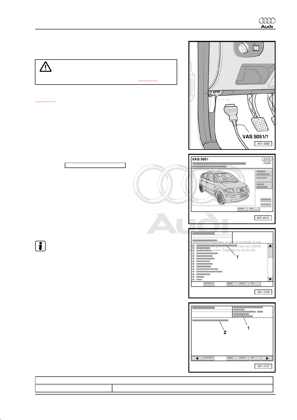
– With ignition switched off, connect up vehicle diagnostic, test‐
ing and information system -VAS 5051 A- with diagnosis lead
-VAS 5051 A/1- to diagnosis connection.
WARNING
Make sure to observe the safety precautions ⇒ page 2 .
Depending on the function required ⇒ Table “Diagnosis functions”
⇒ page 4 :
– Switch on ignition.
or
– Start engine.
Display on -VAS 5051 A- :
– Press the vehicle self-diagnosis key.
Audi TT 1999 ➤
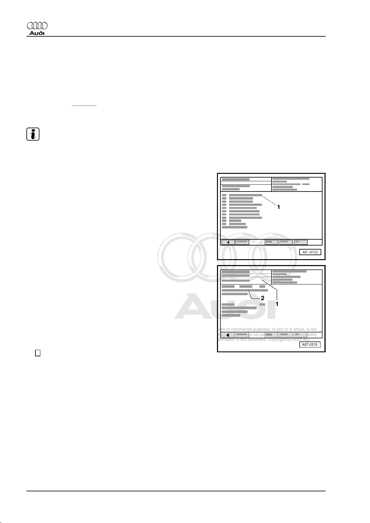
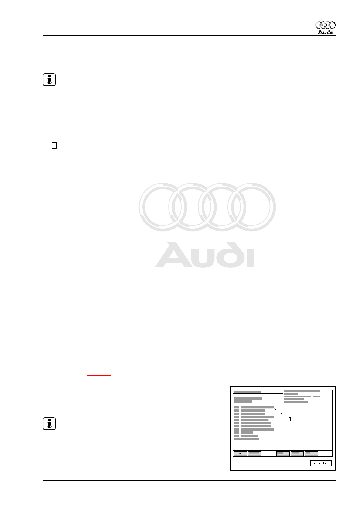
Display on -VAS 5051 A- :
Note
Touching the function “00 - Interrogating fault memory - Overall
system” in the list -1- implements the automatic test sequence,
i.e. the fault memories of all systems with self-diagnosis capability
in the vehicle are interrogated.
– From list -1- select vehicle system “01 Engine electronics”.
– Wait until next readout appears in the display.
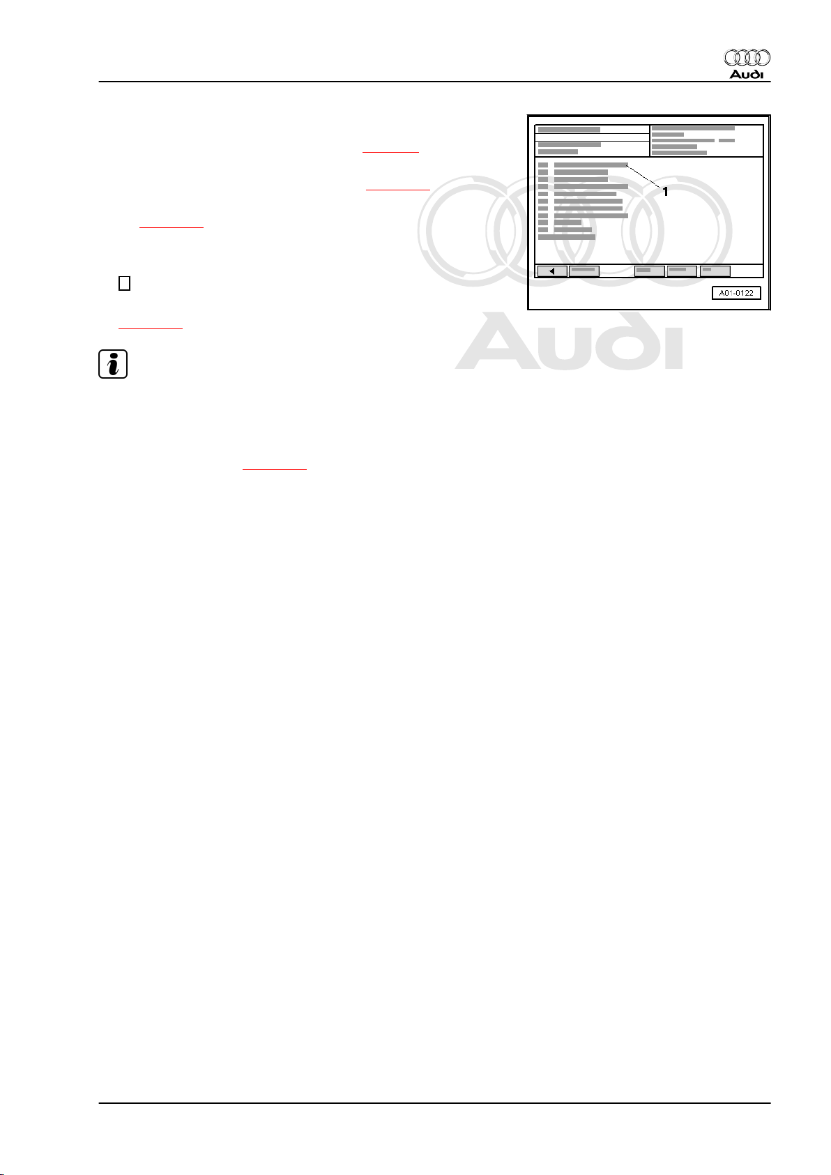
Display on -VAS 5051 A- :
1 - Engine control unit identification
2 - Immobilizer control unit identification
Engine control unit identification (example)
01 - Engine electronics Vehicle system
1. Self-diagnosis of Motronic system 3
Page 8

Protected by copyright. Copying for private or commercial purposes, in part or in whole, is not
permitted unless authorised by AUDI AG. AUDI AG does not guarantee or accept any liability
with respect to the correctness of information in this document. Copyright by AUDI AG.
Audi TT 1999 ➤
Motronic injection and ignition system (4-cylinder) - Edition 05.2005
Engine control unit identification (example)
06A906032.. Part no.; assignment ⇒ Parts catalogue
1.8 ltr. 1) R4/5VT 2) G 3) 0003
4)
Engine capacity
2)
In-line engine, 4-cylinder/5-valve turbo
3)
♦ G = Cruise control system activated
1)
♦ No display = No cruise control system fitted or system not activated
4)
Data level (software version) of control unit
Code 11500 Control unit coding (checking ⇒ page 31 )
Workshop code 12345 Workshop code of -VAS 5051 A- which was used to perform the last cod‐
ing
Immobilizer control unit identification (example)
TRUZZZ8NZ11018983 1) AUZ5Z0Y9122017
2)
1)
17-position vehicle identification No. (chassis num‐
ber)
2)
14-position immobilizer identification number
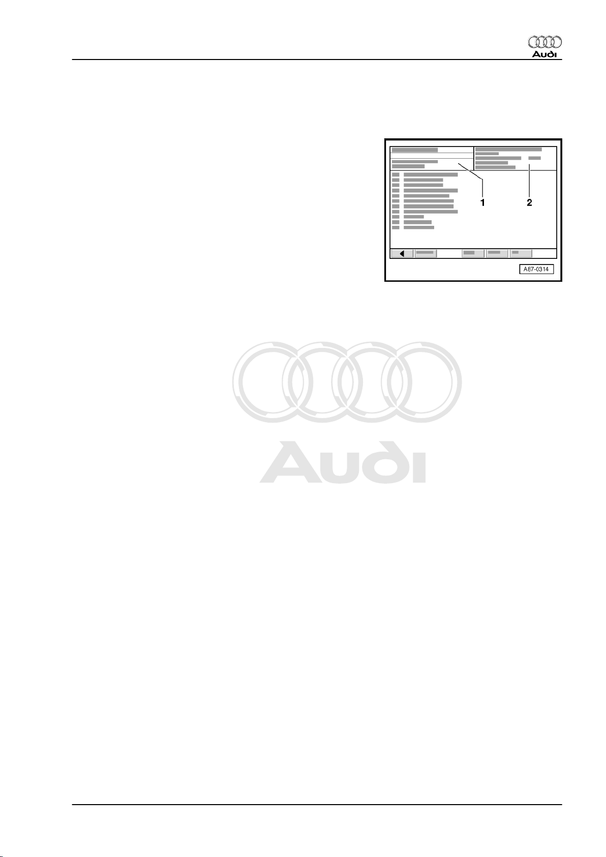
– Press the → key.
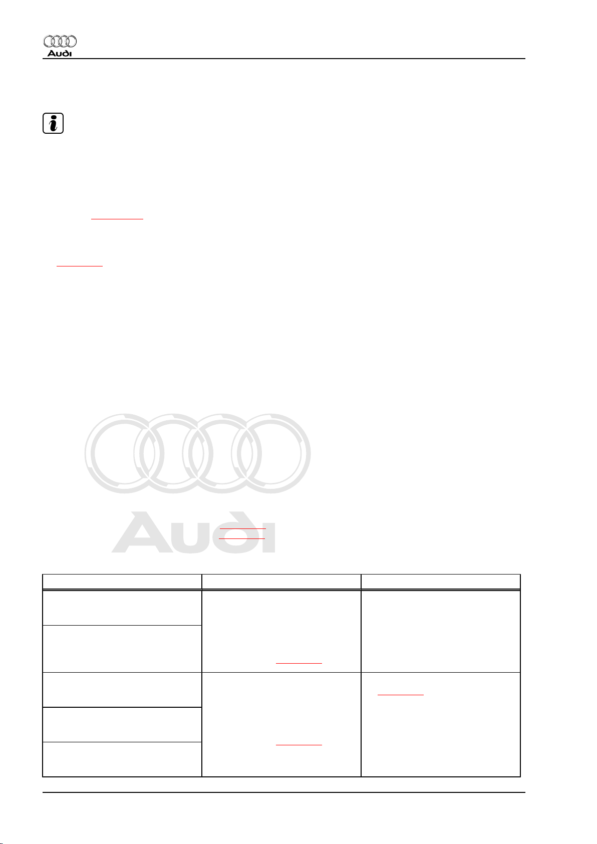
Display on -VAS 5051 A- :
1 - Selection of diagnostic functions:
The following diagnosis functions shown in the display -1- are
available:
Diagnosis functions Page Conditions
02 Interrogate fault memory ⇒ page 6
Ignition on, en‐
gine not running
1)
no
Engine idling Vehicle being
driven
yes yes
03 Final control diagnosis ⇒ page 23 yes no no
04 Basic setting ⇒ page 27 yes yes yes
05 Erase fault memory ⇒ page 29 yes yes yes
06 End output ⇒ page 30 yes yes yes
07 Code control unit ⇒ page 31 yes no no
08 Read measured value block ⇒ page 33 yes yes yes
1)
•
If the engine does not start, turn the engine over for at least 5 seconds using the starter. After doing
this, do not switch off the ignition.
All other functions displayed cannot be selected or can be ignored
in this case.
4 Rep. Gr.01 - Self-diagnosis
Page 9
Protected by copyright. Copying for private or commercial purposes, in part or in whole, is not
permitted unless authorised by AUDI AG. AUDI AG does not guarantee or accept any liability
with respect to the correctness of information in this document. Copyright by AUDI AG.
Motronic injection and ignition system (4-cylinder) - Edition 05.2005
Fault messages on -VAS 5051 A-
If a fault message appears on the display, refer to ⇒ Operating
instructions of vehicle diagnostic, testing and information system
-VAS 5051 A- .
If display zone -1- shows “Vehicle system not available”:
– Check:
♦ Voltage supply to diagnostic connection ⇒ Current flow dia‐
grams, Electrical fault finding and Fitting locations
♦ Wiring between diagnostic connection and engine control unit
⇒ Current flow diagrams, Electrical fault finding and Fitting lo‐
cations.
Audi TT 1999 ➤
1. Self-diagnosis of Motronic system 5
Page 10
Protected by copyright. Copying for private or commercial purposes, in part or in whole, is not
permitted unless authorised by AUDI AG. AUDI AG does not guarantee or accept any liability
with respect to the correctness of information in this document. Copyright by AUDI AG.
Audi TT 1999 ➤
Motronic injection and ignition system (4-cylinder) - Edition 05.2005
2 Interrogating fault memory
2.1 Interrogating fault memory
– Connect vehicle diagnostic, testing and information system -
VAS 5051 A- ⇒ page 2 and select vehicle system “01 - Engine
electronics” from list. When doing this, the engine must be
running at idling speed.
Note
If the engine does not start, turn the engine over for at least 5
seconds using the starter. After doing this, do not switch off the
ignition.
Display on -VAS 5051 A- :
– From list -1-, select diagnosis function “02 - Interrogate fault
memory”.
Display on -VAS 5051 A- :
-1- Content of fault memory No faults detected
or
X faults detected
-2- Fault Fault code
Fault location
Type of fault
A - If faults are detected:
– Print out information on screen or self-diagnosis log.
– Terminate function “02 - Interrogate fault memory” by touching
← key.
6 Rep. Gr.01 - Self-diagnosis
Page 11
Protected by copyright. Copying for private or commercial purposes, in part or in whole, is not
permitted unless authorised by AUDI AG. AUDI AG does not guarantee or accept any liability
with respect to the correctness of information in this document. Copyright by AUDI AG.
Motronic injection and ignition system (4-cylinder) - Edition 05.2005
Display on -VAS 5051 A- :
– Rectify fault(s) according to fault tables ⇒ page 8 .
– From list -1-, select diagnosis function “02 - Interrogate fault
memory” again and erase fault memory ⇒ page 29 .
– Select diagnosis function “06 - End output” from the menu
-1- ⇒ page 30 .
B - If no faults are detected:
– Terminate function “02 - Interrogate fault memory” by touching
← key.
– Select diagnostic function “06 - End output” from list
⇒ page 30 .
Note
♦
If no faults have been stored in the fault memory, do not erase
the fault memory unnecessarily otherwise the readiness code
will be reset.
♦
If the fault memory has been erased, the readiness code must
be generated again ⇒ page 37 .
Audi TT 1999 ➤
2. Interrogating fault memory 7
Page 12
Protected by copyright. Copying for private or commercial purposes, in part or in whole, is not
permitted unless authorised by AUDI AG. AUDI AG does not guarantee or accept any liability
with respect to the correctness of information in this document. Copyright by AUDI AG.
Audi TT 1999 ➤
Motronic injection and ignition system (4-cylinder) - Edition 05.2005
2.2 Fault tables
Note
♦
If faults occur in the monitored sensors or components, these
are stored in the fault memory together with an indication of
the type of fault.
♦
Faults related to the “electronic throttle” are additionally indi‐
cated by the electronic power control fault lamp -K132- (“EPC
lamp”) in the instrument cluster. Notes on electronic throttle
system ⇒ page 108 .
♦
Faults which cause a deterioration in emission levels are in‐
dicated by the exhaust emissions warning lamp -K83- in the
instrument cluster. Notes on exhaust emissions warning lamp
⇒ page 63 .
♦
The fault table is sorted according to the 5-digit fault code in
the left-hand column and the P code.
♦
If a fault is stored in the fault memory and then does not occur
again during the next 40 engine warm-up cycles, the fault will
be automatically erased.
♦
Sporadic faults (temporary faults) are marked “sporadic” on
the display. The word “sporadic” means “intermittent” or “oc‐
curring at irregular intervals”.
♦
The components shown to be defective by the -VAS 5051should not be replaced immediately. Start by using the current
flow diagram to check the wiring and connectors to these com‐
ponents. Also test the earth connections using the current flow
diagram. This is particularly important in the case of “sporadic”
faults.
♦
All adaption values in the control unit are erased if the multipin connectors at the engine control unit are unplugged or the
battery is disconnected. The contents of the fault memory will
remain intact. The next time the engine is started the idling
may be rough at first. In this case, allow the engine to run at
idle for several minutes until the adaption process has been
completed.
♦
If the fault memory has been erased ⇒ page 29 , the readi‐
ness code must be generated again ⇒ page 37 .
2.3 Fault tables for faults 16395 / P0011 to 17608 / P1200
Display on -VAS 5051 A- Explanatory notes Fault remedy
16395 / P0011
Bank 1 camshaft timing control
Specification not attained
16396 / P0012
Bank 1 camshaft timing control
Specification not attained
16485 / P0101
Air mass meter -G70Implausible signal
16486 / P0102
Air mass meter -G70Signal too small
16487 / P0103
Air mass meter -G70Signal too large
♦ If this fault occurs within 3 con‐
secutive driving cycles (engine
operation for at least 5 sec‐
onds), the engine control unit
switches on the exhaust emis‐
sions warning lamp in the instru‐
ment cluster ⇒ page 63
♦ If this fault occurs within 3 con‐
secutive driving cycles (engine
operation for at least 5 sec‐
onds), the engine control unit
switches on the exhaust emis‐
sions warning lamp in the instru‐
ment cluster ⇒ page 63
– Check ⇒ Rep. Gr. 15
– Check air mass meter
⇒ page 80
8 Rep. Gr.01 - Self-diagnosis
Page 13
Protected by copyright. Copying for private or commercial purposes, in part or in whole, is not
permitted unless authorised by AUDI AG. AUDI AG does not guarantee or accept any liability
with respect to the correctness of information in this document. Copyright by AUDI AG.
Audi TT 1999 ➤
Motronic injection and ignition system (4-cylinder) - Edition 05.2005
Display on -VAS 5051 A- Explanatory notes Fault remedy
16490 / P0106
Intake manif.press./air press ⇒ G71- / -F96Implausible signal
♦ The intake manifold pressure is
determined by the charge air
pressure sender -G31- (instead
of -G71- displayed); the atmos‐
– Check charge air pressure
sender -G31- ⇒ Rep. Gr. 21
pheric pressure is determined
by the altitude sender -F96- (in
the engine control unit)
♦ If this fault occurs within 3 con‐
secutive driving cycles (engine
operation for at least 5 sec‐
onds), the engine control unit
switches on the exhaust emis‐
sions warning lamp in the instru‐
ment cluster ⇒ page 63
16496 / P0112
Intake air temperature sender G42Signal too small
16497 / P0113
Intake air temperature sender G42Signal too large
16500 / P0116
Coolant temperature sender -G62Implausible signal
16501 / P0117
Coolant temperature sender -G62Signal too small
16502 / P0118
Coolant temperature sender -G62Signal too large
16514 / P0130
Bank 1, probe 1
Electrical fault in current circuit
16515 / P0131
Bank 1, probe 1
Voltage too low
16516 / P0132
Bank 1, probe 1
Voltage too high
16517 / P0133
Bank 1, probe 1
Signal too slow
16518 / P0134
Bank 1, probe 1
No activity
16519 / P0135
Bank 1, probe 1
Electrical fault in heating element
circuit
♦ If this fault occurs within 3 con‐
secutive driving cycles (engine
operation for at least 5 sec‐
onds), the engine control unit
switches on the exhaust emis‐
sions warning lamp in the instru‐
ment cluster ⇒ page 63
♦ If this fault occurs within 3 con‐
secutive driving cycles (engine
operation for at least 5 sec‐
onds), the engine control unit
switches on the exhaust emis‐
sions warning lamp in the instru‐
ment cluster ⇒ page 63
♦ If this fault occurs within 3 con‐
secutive driving cycles (engine
operation for at least 5 sec‐
onds), the engine control unit
switches on the exhaust emis‐
sions warning lamp in the instru‐
ment cluster ⇒ page 63
– Check intake air temperature
sender ⇒ page 157
– Check coolant temperature
sender ⇒ page 162
– Check Lambda probe and
Lambda control before catalytic
converter ⇒ page 86
2. Interrogating fault memory 9
Page 14

Protected by copyright. Copying for private or commercial purposes, in part or in whole, is not
permitted unless authorised by AUDI AG. AUDI AG does not guarantee or accept any liability
with respect to the correctness of information in this document. Copyright by AUDI AG.
Audi TT 1999 ➤
Motronic injection and ignition system (4-cylinder) - Edition 05.2005
Display on -VAS 5051 A- Explanatory notes Fault remedy
16520 / P0136
Bank 1, probe 2
Electrical fault in current circuit
16521 / P0137
Bank 1, probe 2
Voltage too low
♦ If this fault occurs within 3 con‐
secutive driving cycles (engine
operation for at least 5 sec‐
onds), the engine control unit
switches on the exhaust emis‐
sions warning lamp in the instru‐
ment cluster ⇒ page 63
– Check Lambda probe and
Lambda control after catalytic
converter ⇒ page 95
16522 / P0138
Bank 1, probe 2
Voltage too high
16523 / P0139
Bank 1, probe 2
Signal too slow
16524 / P0140
Bank 1, probe 2
No activity
16620 / P0236
Charge pressure sender -G31Implausible signal
16621 / P0237
Charge pressure sender -G31Signal too small
♦ If this fault occurs within 3 con‐
secutive driving cycles (engine
operation for at least 5 sec‐
onds), the engine control unit
switches on the exhaust emis‐
sions warning lamp in the instru‐
ment cluster ⇒ page 63
– Check charge air pressure
sender⇒ Rep. Gr. 21
16622 / P0238
Charge pressure sender -G31Signal too large
16684 / P0300
Misfiring recognised
16685 / P0301
Cyl. 1 Misfiring recognised
16686 / P0302
Cyl. 2 Misfiring recognised
16687 / P0303
Cyl. 3 Misfiring recognised
♦ If this fault occurs within 3 con‐
secutive driving cycles (engine
operation for at least 5 sec‐
onds), the engine control unit
switches on the exhaust emis‐
sions warning lamp in the instru‐
ment cluster ⇒ page 63
– Check fuel pressure
⇒ page 67
– Check injectors ⇒ page 70
– Check spark plugs and ignition
cables with connectors
– Check ignition coils with output
stages ⇒ page 149
16688 / P0304
Cyl. 4 Misfiring recognised
– Check misfiring detection
⇒ page 173
16705 / P0321
Engine speed sender -G28Implausible signal
16706 / P0322
Engine speed sender -G28No signal
10 Rep. Gr.01 - Self-diagnosis
♦ If this fault occurs within 3 con‐
secutive driving cycles (engine
operation for at least 5 sec‐
onds), the engine control unit
switches on the exhaust emis‐
sions warning lamp in the instru‐
ment cluster ⇒ page 63
♦ This fault causes the engine
control unit to activate the EPC
lamp in the instrument cluster
⇒ page 108
– Put fuel in fuel tank
– Check engine speed sender
⇒ page 159
Page 15
Protected by copyright. Copying for private or commercial purposes, in part or in whole, is not
permitted unless authorised by AUDI AG. AUDI AG does not guarantee or accept any liability
with respect to the correctness of information in this document. Copyright by AUDI AG.
Audi TT 1999 ➤
Motronic injection and ignition system (4-cylinder) - Edition 05.2005
Display on -VAS 5051 A- Explanatory notes Fault remedy
16711 / P0327
Knock sensor 1 -G61Signal too small
16712 / P0328
Knock sensor 1 -G61Signal too large
♦ If this fault occurs within 3 con‐
secutive driving cycles (engine
operation for at least 5 sec‐
onds), the engine control unit
switches on the exhaust emis‐
sions warning lamp in the instru‐
ment cluster ⇒ page 63
– Check for corrosion in connec‐
tion between knock sensor and
wiring harness
– Check knock sensor
⇒ page 168
16716 / P0332
Knock sensor 2 -G66Signal too small
16717 / P0333
Knock sensor 2 -G66Signal too large
16725 / P0341
Camshaft pos. sensor ⇒ sender G40Implausible signal
16726 / P0342
Camshaft pos. sensor ⇒ sender G40Signal too small
16727 / P0343
Camshaft pos. sensor ⇒ sender -
♦ If this fault occurs within 3 con‐
secutive driving cycles (engine
operation for at least 5 sec‐
onds), the engine control unit
switches on the exhaust emis‐
sions warning lamp in the instru‐
ment cluster ⇒ page 63
♦ The Hall sender is referred to as
-G163- in the current flow dia‐
grams.
– Check Hall sender -G163-
⇒ page 170
G40Signal too large
16795 / P0411
Secondary air system
Through-flow defective
♦ If this fault occurs within 3 con‐
secutive driving cycles (engine
operation for at least 5 sec‐
onds), the engine control unit
– Check hoses (secondary air in‐
let valve); check intake system
for leaks (unmetered air)
⇒ page 83
switches on the exhaust emis‐
sions warning lamp in the instru‐
ment cluster ⇒ page 63
– Check secondary air system ⇒
Rep. Gr. 26
16804 / P0420
Bank 1, catalytic converter system
Efficiency too low
16806 / P0422
Bank 1, main catalytic converter
Efficiency too low
16825 / P0441
Tank breathing system
Flow rate faulty
16885 / P0501
Vehicle speed signal
Implausible signal
♦ If this fault occurs within 3 con‐
secutive driving cycles (engine
operation for at least 5 sec‐
onds), the engine control unit
switches on the exhaust emis‐
sions warning lamp in the instru‐
ment cluster ⇒ page 63
♦ If this fault occurs within 3 con‐
secutive driving cycles (engine
operation for at least 5 sec‐
onds), the engine control unit
switches on the exhaust emis‐
sions warning lamp in the instru‐
ment cluster ⇒ page 63
♦ If this fault occurs within 3 con‐
secutive driving cycles (engine
operation for at least 5 sec‐
onds), the engine control unit
switches on the exhaust emis‐
sions warning lamp in the instru‐
ment cluster ⇒ page 63
– Generate readiness code
⇒ page 37 . If the same fault is
displayed again, renew catalytic
converter ⇒ Rep. Gr. 26
– Check solenoid valve 1 for acti‐
vated charcoal filter -N80-
⇒ page 105
– Check vehicle speed signal
⇒ page 131
2. Interrogating fault memory 11
Page 16
Protected by copyright. Copying for private or commercial purposes, in part or in whole, is not
permitted unless authorised by AUDI AG. AUDI AG does not guarantee or accept any liability
with respect to the correctness of information in this document. Copyright by AUDI AG.
Audi TT 1999 ➤
Motronic injection and ignition system (4-cylinder) - Edition 05.2005
Display on -VAS 5051 A- Explanatory notes Fault remedy
16890 / P0506
Idling speed control
Revs below specification
16891 / P0507
Idling speed control
Revs above specification
♦ If this fault occurs within 3 con‐
secutive driving cycles (engine
operation for at least 5 sec‐
onds), the engine control unit
switches on the exhaust emis‐
sions warning lamp in the instru‐
ment cluster ⇒ page 63
– Check throttle valve module -
J338- ⇒ page 109
– Check hoses (secondary air in‐
let valve); check intake system
for leaks (unmetered air)
⇒ page 83
16944 / P0560
Voltage supply
Implausible signal
16946 / P0562
Voltage supply
Voltage too low
16947 / P0563
Voltage supply
Voltage too high
16955 / P0571
Brake light switch -FImplausible signal
16985 / P0601
Control unit defective
16988 / P0604
Control unit defective
16989 / P0605
Control unit defective
16990 / P0606
Control unit defective
17069 / P0685
Main relay ⇒ -J271Open circuit
17070 / P0686
Main relay ⇒ -J271Short to earth
17071 / P0687
Main relay ⇒ -J271Short to positive
17072 / P0688
Main relay, load circuit ⇒ -J271Open circuit
17510 / P1102
Bank 1, probe 1, heating element
circuit
Short to positive
♦ In addition to the brake light
switch -F- , the brake pedal
switch -F47- is also monitored
♦ If this fault occurs within 3 con‐
secutive driving cycles (engine
operation for at least 5 sec‐
onds), the engine control unit
switches on the exhaust emis‐
sions warning lamp in the instru‐
ment cluster ⇒ page 63
♦ If this fault occurs within 3 con‐
secutive driving cycles (engine
operation for at least 5 sec‐
onds), the engine control unit
switches on the exhaust emis‐
sions warning lamp in the instru‐
ment cluster ⇒ page 63
♦ If this fault occurs within 3 con‐
secutive driving cycles (engine
operation for at least 5 sec‐
onds), the engine control unit
switches on the exhaust emis‐
sions warning lamp in the instru‐
ment cluster ⇒ page 63
– Check voltage supply of engine
control unit ⇒ page 165
– Check brake light switch and
brake pedal switch ⇒ page 121
– Renew engine control unit
⇒ “1.9 Removing and installing
engine control unit without pro‐
tective housing”, page 59 or
⇒ “1.10 Removing and installing
engine control unit with protec‐
tive housing”, page 61
– Check Motronic current supply
relay -J271- ⇒ page 152
– Check Lambda probe heating
before catalytic converter
⇒ page 93
17511 / P1103
Bank 1, probe 2, heating element
circuit
Performance too low
17513 / P1105
Bank 1, probe 2, heating element
circuit
Short to positive
12 Rep. Gr.01 - Self-diagnosis
♦ If this fault occurs within 3 con‐
secutive driving cycles (engine
operation for at least 5 sec‐
onds), the engine control unit
switches on the exhaust emis‐
sions warning lamp in the instru‐
ment cluster ⇒ page 63
– Check Lambda probe heating
after catalytic converter
⇒ page 101
Page 17
Protected by copyright. Copying for private or commercial purposes, in part or in whole, is not
permitted unless authorised by AUDI AG. AUDI AG does not guarantee or accept any liability
with respect to the correctness of information in this document. Copyright by AUDI AG.
Audi TT 1999 ➤
Motronic injection and ignition system (4-cylinder) - Edition 05.2005
Display on -VAS 5051 A- Explanatory notes Fault remedy
17519 / P1111
Lambda control (bank 1)
– Check Lambda control before
catalytic converter ⇒ page 86
System too lean
17520 / P1112
Lambda control (bank 1)
System too rich
17521 / P1113
Bank 1, probe 1
Internal resistance too high
– Start by checking for contact re‐
sistance in signal wires
⇒ page 90 ; if there is no con‐
tact resistance: renew Lambda
probe
17522 / P1114
Bank 1, probe 2
Internal resistance too high
♦ If this fault occurs within 3 con‐
secutive driving cycles (engine
operation for at least 5 sec‐
onds), the engine control unit
switches on the exhaust emis‐
– Start by checking for contact re‐
sistance in signal wires
⇒ page 100 ; if there is no con‐
tact resistance: renew Lambda
probe
sions warning lamp in the instru‐
ment cluster ⇒ page 63
17523 / P1115
Bank 1, probe 1, heating element
circuit
Short to earth
17524 / P1116
Bank 1, probe 1, heating element
circuit
Open circuit
17525 / P1117
Bank 1, probe 2, heating element
circuit
Short to earth
17526 / P1118
Bank 1, probe 2, heating element
circuit
Open circuit
17535 / P1127
Bank 1, mixture adaption (mult.)
System too rich
17536 / P1128
Bank 1, mixture adaption (mult.)
System too lean
♦ If this fault occurs within 3 con‐
secutive driving cycles (engine
operation for at least 5 sec‐
onds), the engine control unit
switches on the exhaust emis‐
sions warning lamp in the instru‐
ment cluster ⇒ page 63
♦ If this fault occurs within 3 con‐
secutive driving cycles (engine
operation for at least 5 sec‐
onds), the engine control unit
switches on the exhaust emis‐
sions warning lamp in the instru‐
ment cluster ⇒ page 63
♦ “mult.” (= multiplicative) indi‐
cates that the fault takes effect
over the entire engine speed
and load range
– Check Lambda probe heating
before catalytic converter
⇒ page 93
– Check Lambda probe heating
after catalytic converter
⇒ page 101
– Perform road test (fuel in oil)
– Check fuel system pressure
⇒ page 67
– Check air mass meter
⇒ page 80
– Check intake system for leaks
(unmetered air) ⇒ page 83
– Check Lambda probe before
catalytic converter ⇒ page 86
– Check Lambda probe after cat‐
alytic converter ⇒ page 95
– Check injectors ⇒ page 70
2. Interrogating fault memory 13
Page 18
Protected by copyright. Copying for private or commercial purposes, in part or in whole, is not
permitted unless authorised by AUDI AG. AUDI AG does not guarantee or accept any liability
with respect to the correctness of information in this document. Copyright by AUDI AG.
Audi TT 1999 ➤
Motronic injection and ignition system (4-cylinder) - Edition 05.2005
Display on -VAS 5051 A- Explanatory notes Fault remedy
17544 / P1136
Bank 1, mixture adaption (add.)
System too lean
17545 / P1137
Bank 1, mixture adaption (add.)
System too rich
♦ “add.” = additive, i.e. the fault
only occurs at idling speed
– Perform road test (fuel in oil)
– Check fuel system pressure
⇒ page 67
– Check air mass meter -G70-
⇒ page 80
– Check intake system for leaks
(unmetered air) ⇒ page 83
– Check Lambda probe after cat‐
alytic converter ⇒ page 95
– Check solenoid valve 1 for acti‐
vated charcoal filter -N80-
⇒ page 105
17551 / P1143
Load determination
Level exceeded
♦ If this fault occurs within 3 con‐
secutive driving cycles (engine
operation for at least 5 sec‐
onds), the engine control unit
switches on the exhaust emis‐
– Check air mass meter -G70-
⇒ page 80
– Check throttle valve module -
J338- ⇒ page 109
sions warning lamp in the instru‐
ment cluster ⇒ page 63
17557 / P1149
Lambda control bank 1
Implausible control value
17579 / P1171
Angle sens. 2 for throt. valve drive G188Implausible signal
17580 / P1172
Angle sens. 2 for throt. valve drive G188Signal too low
17581 / P1173
Angle sens. 2 for throt. valve drive G188Signal too high
17584 / P1176
Bank 1, Lambda corr. after catalytic
converter
Control limit reached
♦ If this fault occurs within 3 con‐
secutive driving cycles (engine
operation for at least 5 sec‐
onds), the engine control unit
switches on the exhaust emis‐
sions warning lamp in the instru‐
ment cluster ⇒ page 63
♦ This fault causes the engine
control unit to activate the EPC
lamp in the instrument cluster
⇒ page 108
♦ If this fault occurs within 3 con‐
secutive driving cycles (engine
operation for at least 5 sec‐
onds), the engine control unit
switches on the exhaust emis‐
sions warning lamp in the instru‐
ment cluster ⇒ page 63
– Check Lambda probe learnt val‐
ues and Lambda control
⇒ page 88
– Check fuel system pressure
⇒ page 67
– Check intake system for leaks
(unmetered air) ⇒ page 83
– Check angle sender for throttle
valve drive ⇒ page 112
– Check ageing of Lambda probe
before catalytic converter
⇒ page 90
– Check Lambda probe and
Lambda control after catalytic
converter ⇒ page 95
17606 / P1198
Bank 1, probe 2, heating element
circuit
Electrical fault
17608 / P1200
Air recirculation valve for turbo‐
charger -N249Mechanical fault
14 Rep. Gr.01 - Self-diagnosis
– Check Lambda probe heating
after catalytic converter
⇒ page 101
– Check vacuum system for leaks
– Check air recirculation valve for
turbocharger -N249- ⇒ Rep. Gr.
21
Page 19

Protected by copyright. Copying for private or commercial purposes, in part or in whole, is not
permitted unless authorised by AUDI AG. AUDI AG does not guarantee or accept any liability
with respect to the correctness of information in this document. Copyright by AUDI AG.
Audi TT 1999 ➤
Motronic injection and ignition system (4-cylinder) - Edition 05.2005
2.4 Fault tables for faults 17621 / P1231 to 19534 / P3078
Display on -VAS 5051 A- Explanatory notes Fault remedy
17621 / P1213
Injector Cyl. 1 -N30Short to Positive
17622 / P1214
Injector Cyl. 2 -N31Short to Positive
17623 / P1215
Injector Cyl. 3 -N32- Short to Posi‐
tive
17624 / P1216
Injector Cyl. 4 -N33Short to Positive
17633 / P1225
Injector Cyl. 1 -N30Short to Earth
17634 / P1226
Injector Cyl. 2 -N31Short to Earth
17635 / P1227
Injector Cyl. 3 -N32Short to Earth
17636 / P1228
Injector Cyl. 4 -N33Short to Earth
17645 / P1237
Injector Cyl. 1 -N30Open circuit
17646 / P1238
Injector Cyl. 2 -N31Open circuit
17647 / P1239
Injector Cyl. 3 -N32Open circuit
17648 / P1240
Injector Cyl. 4 -N33Open circuit
17658 / P1250
Fuel status too low
♦ If this fault occurs within 3 con‐
secutive driving cycles (engine
operation for at least 5 sec‐
onds), the engine control unit
switches on the exhaust emis‐
sions warning lamp in the instru‐
ment cluster ⇒ page 63
♦ The fault “fuel status too low” is
stored in conjunction with misfir‐
ing or faults relating to Lambda
control if there is or has been in‐
sufficient fuel in the tank; the
fault remains static in the fault
memory and is not set to spora‐
dic even if (for example) the ve‐
hicle has been re-fuelled in the
meantime
– Check injectors ⇒ page 70
– Fault resulting from earlier prob‐
lem ⇒ “Explanatory notes”
– Fill fuel tank and erase fault
memory
– Interrogate fault memory of in‐
strument cluster ⇒ Electrical
system, self-diagnosis; Rep.
Gr. 01
2. Interrogating fault memory 15
Page 20
Protected by copyright. Copying for private or commercial purposes, in part or in whole, is not
permitted unless authorised by AUDI AG. AUDI AG does not guarantee or accept any liability
with respect to the correctness of information in this document. Copyright by AUDI AG.
Audi TT 1999 ➤
Motronic injection and ignition system (4-cylinder) - Edition 05.2005
Display on -VAS 5051 A- Explanatory notes Fault remedy
17695 / P1287
Air recirc. valve for turbocharger N249Open circuit
17696 / P1288
Air recirc. valve for turbocharger N249-
♦ If this fault occurs within 3 con‐
secutive driving cycles (engine
operation for at least 5 sec‐
onds), the engine control unit
switches on the exhaust emis‐
sions warning lamp in the instru‐
ment cluster ⇒ page 63
– Check air recirculation valve for
turbocharger ⇒ Rep. Gr. 21
Short to positive
17697 / P1289
Air recirc. valve for turbocharger N249Short to earth
17704 / P1296
– Check ⇒ Rep. Gr. 19
Fault in cooling system
17705 / P1297
– Check ⇒ Rep. Gr. 21
Turbocharger/throttle valve con‐
nection
Drop in pressure
17733 / P1325
Knock control Cylinder 1
– Check knock control
⇒ page 166
Control limit reached
17734 / P1326
Knock control Cylinder 2
Control limit reached
17735 / P1327
Knock control Cylinder 3
Control limit reached
17736 / P1328
Knock control Cylinder 4
Control limit reached
17743 / P1335
Engine torque monitoring 2
Control limit surpassed
♦ If this fault occurs within 3 con‐
secutive driving cycles (engine
operation for at least 5 sec‐
– Major leak; check intake system
for leaks (unmetered air)
⇒ page 83
onds), the engine control unit
switches on the exhaust emis‐
sions warning lamp in the instru‐
– Check intake air temperature
sender -G42- ⇒ page 157
ment cluster ⇒ page 63
– Check air mass meter -G70-
⇒ page 80
– Check coolant temperature
sender -G62- ⇒ page 162
17744 / P1336
♦ This fault causes the engine
control unit to activate the EPC
lamp in the instrument cluster
⇒ page 108
Engine torque monitoring
Control limit surpassed
17748 / P1340
Camshaft pos./crankshaft pos.
sens.
Wrong allocation
♦ If this fault occurs within 3 con‐
secutive driving cycles (engine
operation for at least 5 sec‐
onds), the engine control unit
switches on the exhaust emis‐
– Unscrew Hall sender and check
proper installation of rotor ring at
camshaft. (If incorrectly instal‐
led, the retainer tab will be
squashed on tightening the bolt)
sions warning lamp in the instru‐
ment cluster ⇒ page 63
– Also check valve timing ⇒ Rep.
Gr. 13
16 Rep. Gr.01 - Self-diagnosis
Page 21
Protected by copyright. Copying for private or commercial purposes, in part or in whole, is not
permitted unless authorised by AUDI AG. AUDI AG does not guarantee or accept any liability
with respect to the correctness of information in this document. Copyright by AUDI AG.
Audi TT 1999 ➤
Motronic injection and ignition system (4-cylinder) - Edition 05.2005
Display on -VAS 5051 A- Explanatory notes Fault remedy
17763 / P1355
Ignition circuit, cylinder 1
Open circuit
17764 / P1356
Ignition circuit, cylinder 1
Short to Positive
♦ If this fault occurs within 3 con‐
secutive driving cycles (engine
operation for at least 5 sec‐
onds), the engine control unit
switches on the exhaust emis‐
sions warning lamp in the instru‐
ment cluster ⇒ page 63
– Check ignition coils with output
stages ⇒ page 149
17765 / P1357
Ignition circuit, cylinder 1
Short to Earth
17766 / P1358
Ignition circuit, cylinder 2
Open circuit
17767 / P1359
Ignition circuit, cylinder 2
Short to Positive
17768 / P1360
Ignition circuit, cylinder 2
Short to Earth
17769 / P1361
Ignition circuit, cylinder 3
Open circuit
17770 / P1362
Ignition circuit, cylinder 3
Short to Positive
17771 / P1363
Ignition circuit, cylinder 3
Short to Earth
17772 / P1364
Ignition circuit, cylinder 4
Open circuit
17773 / P1365
Ignition circuit, cylinder 4
Short to Positive
17774 / P1366
Ignition circuit, cylinder 4
Short to Earth
17794 / P1386
Control unit defective
17795 / P1387
Control unit defective
♦ If this fault occurs within 3 con‐
secutive driving cycles (engine
operation for at least 5 sec‐
onds), the engine control unit
switches on the exhaust emis‐
sions warning lamp in the instru‐
ment cluster ⇒ page 63
– Renew engine control unit
⇒ “1.9 Removing and installing
engine control unit without pro‐
tective housing”, page 59 or
⇒ “1.10 Removing and installing
engine control unit with protec‐
tive housing”, page 61
17796 / P1388
Control unit defective
♦ If this fault occurs within 3 con‐
secutive driving cycles (engine
operation for at least 5 sec‐
onds), the engine control unit
switches on the exhaust emis‐
sions warning lamp in the instru‐
ment cluster ⇒ page 63
♦ This fault causes the engine
control unit to activate the EPC
lamp in the instrument cluster
⇒ page 108
2. Interrogating fault memory 17
Page 22
Protected by copyright. Copying for private or commercial purposes, in part or in whole, is not
permitted unless authorised by AUDI AG. AUDI AG does not guarantee or accept any liability
with respect to the correctness of information in this document. Copyright by AUDI AG.
Audi TT 1999 ➤
Motronic injection and ignition system (4-cylinder) - Edition 05.2005
Display on -VAS 5051 A- Explanatory notes Fault remedy
17818 / P1410
Tank breathing valve -N80Short to positive
♦ If this fault occurs within 3 con‐
secutive driving cycles (engine
operation for at least 5 sec‐
– Check solenoid valve 1 for acti‐
vated charcoal filter -N80-
⇒ page 105
onds), the engine control unit
switches on the exhaust emis‐
sions warning lamp in the instru‐
ment cluster ⇒ page 63
17829 / P1421
Secondary air inlet valve -N112Short to earth
17830 / P1422
Secondary air inlet valve -N112Short to positive
17832 / P1424
Bank 1, Secondary air system
Leak recognised
17833 / P1425
Tank breathing valve -N80Short to earth
17834 / P1426
Tank breathing valve -N80Open circuit
17835 / P1427
Activation, vacuum pump for
brakes
Short to positive
17836 / P1428
Activation, vacuum pump for
brakes
Short to positive
17837 / P1429
Activation, vacuum pump for
brakes
Open circuit
17840 / P1432
Secondary air inlet valve -N112Open circuit
17841 / P1433
Relay for secondary air pump J229Open circuit
17842 / P1434
Relay for secondary air pump J229Short to Positive
17843 / P1435
Relay for secondary air pump J229Short to earth
17909 / P1501
Fuel pump relay -J17Short to earth
17910 / P1502
Fuel pump relay -J17Short to positive
♦ If this fault occurs within 3 con‐
secutive driving cycles (engine
operation for at least 5 sec‐
onds), the engine control unit
switches on the exhaust emis‐
sions warning lamp in the instru‐
ment cluster ⇒ page 63
♦ If this fault occurs within 3 con‐
secutive driving cycles (engine
operation for at least 5 sec‐
onds), the engine control unit
switches on the exhaust emis‐
sions warning lamp in the instru‐
ment cluster ⇒ page 63
♦ If this fault occurs within 3 con‐
secutive driving cycles (engine
operation for at least 5 sec‐
onds), the engine control unit
switches on the exhaust emis‐
sions warning lamp in the instru‐
ment cluster ⇒ page 63
♦ If this fault occurs within 3 con‐
secutive driving cycles (engine
operation for at least 5 sec‐
onds), the engine control unit
switches on the exhaust emis‐
sions warning lamp in the instru‐
ment cluster ⇒ page 63
– Check secondary air inlet valve
-N112- ⇒ Rep. Gr. 26
– Check hoses and components
of secondary air system ⇒ Rep.
Gr. 26
– Check solenoid valve 1 for acti‐
vated charcoal filter -N80-
⇒ page 105
– Check brake vacuum pump ⇒
Rep. Gr. 47
– Check secondary air inlet valve
-N112- ⇒ Rep. Gr. 26
– Check secondary air pump relay
-J229- ⇒ Rep. Gr. 26
– Check fuel pump relay
⇒ page 77
18 Rep. Gr.01 - Self-diagnosis
Page 23
Protected by copyright. Copying for private or commercial purposes, in part or in whole, is not
permitted unless authorised by AUDI AG. AUDI AG does not guarantee or accept any liability
with respect to the correctness of information in this document. Copyright by AUDI AG.
Audi TT 1999 ➤
Motronic injection and ignition system (4-cylinder) - Edition 05.2005
Display on -VAS 5051 A- Explanatory notes Fault remedy
17927 / P1519
Bank 1, camshaft timing control
Faulty
♦ If this fault occurs within 3 con‐
secutive driving cycles (engine
operation for at least 5 sec‐
– Check ⇒ Rep. Gr. 15
onds), the engine control unit
switches on the exhaust emis‐
sions warning lamp in the instru‐
ment cluster ⇒ page 63
17931 / P1523
Crash signal from airbag control
unit
Implausible signal
17937 / P1529
Variable valve timing
Short to positive
17938 / P1530
Variable valve timing
Short to earth
17939 / P1531
Variable valve timing
Open circuit
17947 / P1539
Clutch pedal switch -F36Implausible signal
17949 / P1541
Fuel pump relay -J17Open circuit
♦ This fault is stored if the corre‐
sponding signal is received from
the airbag control unit
♦ If this fault occurs within 3 con‐
secutive driving cycles (engine
operation for at least 5 sec‐
onds), the engine control unit
switches on the exhaust emis‐
sions warning lamp in the instru‐
ment cluster ⇒ page 63
♦ If this fault occurs within 3 con‐
secutive driving cycles (engine
operation for at least 5 sec‐
onds), the engine control unit
switches on the exhaust emis‐
sions warning lamp in the instru‐
ment cluster ⇒ page 63
♦ If this fault occurs within 3 con‐
secutive driving cycles (engine
operation for at least 5 sec‐
onds), the engine control unit
switches on the exhaust emis‐
sions warning lamp in the instru‐
ment cluster ⇒ page 63
– Check ⇒ Body, self-diagnosis;
Rep. Gr. 01
– Check ⇒ Rep. Gr. 15
– Check clutch pedal switch
⇒ page 125
– Check fuel pump relay
⇒ page 77
17950 / P1542
Angle sender for throt. val. drive G187Implausible signal
17951 / P1543
Angle sender for throt. val. drive G187Signal too low
17952 / P1544
Angle sender for throt. val. drive G187Signal too high
17953 / P1545
Throttle valve control
Faulty
♦ If this fault occurs within 3 con‐
secutive driving cycles (engine
operation for at least 5 sec‐
onds), the engine control unit
switches on the exhaust emis‐
sions warning lamp in the instru‐
ment cluster ⇒ page 63
♦ This fault causes the engine
control unit to activate the EPC
lamp in the instrument cluster
⇒ page 108
– Check angle sender for throttle
valve drive ⇒ page 112
– Check throttle valve module -
J338- ⇒ page 109
2. Interrogating fault memory 19
Page 24
Protected by copyright. Copying for private or commercial purposes, in part or in whole, is not
permitted unless authorised by AUDI AG. AUDI AG does not guarantee or accept any liability
with respect to the correctness of information in this document. Copyright by AUDI AG.
Audi TT 1999 ➤
Motronic injection and ignition system (4-cylinder) - Edition 05.2005
Display on -VAS 5051 A- Explanatory notes Fault remedy
17954 / P1546
– Check ⇒ Rep. Gr. 21
Charge press. control solenoid
valve -N75Short to positive
17955 / P1547
Charge press. control solenoid
valve -N75Short to earth
17956 / P1548
Charge press. control solenoid
valve -N75Open circuit
17958 / P1550
Charge pressure
Control difference
17963 / P1555
Maximum charge pressure sur‐
passed
17964 / P1556
Charge pressure control
Regulating limit not reached
17965 / P1557
Charge pressure control
Regulating limit surpassed
17966 / P1558
Throttle valve drive -G186Fault in electrical circuit
♦ If this fault occurs within 3 con‐
secutive driving cycles (engine
operation for at least 5 sec‐
– Check throttle valve module -
J338- ⇒ page 109
onds), the engine control unit
switches on the exhaust emis‐
sions warning lamp in the instru‐
ment cluster ⇒ page 63
♦ This fault causes the engine
control unit to activate the EPC
lamp in the instrument cluster
⇒ page 108
17967 / P1559
Throttle valve module -J338Fault in basic setting
17968 / P1560
Maximum engine revs
surpassed
17972 / P1564
Throttle valve module -J338Low voltage in basic setting
17973 / P1565
Throttle valve module -J338Lower stop not reached
17976 / P1568
Throttle valve module -J338Mechanical fault
♦ If this fault occurs within 3 con‐
– Perform adaption ⇒ page 110
secutive driving cycles (engine
operation for at least 5 sec‐
onds), the engine control unit
switches on the exhaust emis‐
sions warning lamp in the instru‐
ment cluster ⇒ page 63
♦ Engine has been overrevved – Repair mechanical damage
– Charge battery and repeat basic
setting
♦ If this fault occurs within 3 con‐
secutive driving cycles (engine
– Check throttle valve module
⇒ page 109
operation for at least 5 sec‐
onds), the engine control unit
switches on the exhaust emis‐
sions warning lamp in the instru‐
ment cluster ⇒ page 63
♦ This fault causes the engine
control unit to activate the EPC
lamp in the instrument cluster
⇒ page 108
20 Rep. Gr.01 - Self-diagnosis
Page 25
Protected by copyright. Copying for private or commercial purposes, in part or in whole, is not
permitted unless authorised by AUDI AG. AUDI AG does not guarantee or accept any liability
with respect to the correctness of information in this document. Copyright by AUDI AG.
Audi TT 1999 ➤
Motronic injection and ignition system (4-cylinder) - Edition 05.2005
Display on -VAS 5051 A- Explanatory notes Fault remedy
17977 / P1569
CCS switch -E45-
– Check ⇒ Electrical system, self-
diagnosis; Rep. Gr. 01
Implausible signal
17978 / P1570
Engine control unit
blocked
– Adapt electronic immobilizer to
engine control unit ⇒ Electrical
system, self-diagnosis; Rep.
Gr. 01
17987 / P1579
Throttle valve module -J338Adaption not started
– Perform adaption of throttle
valve module in accordance
with test requirements
⇒ page 110
18010 / P1602
Voltage supply term. 30
– Check voltage supply of engine
control unit ⇒ page 165
Voltage too low
18011 / P1603
Control unit defective
♦ If this fault occurs within 3 con‐
secutive driving cycles (engine
operation for at least 5 sec‐
onds), the engine control unit
switches on the exhaust emis‐
sions warning lamp in the instru‐
ment cluster ⇒ page 63
– Renew engine control unit
⇒ “1.9 Removing and installing
engine control unit without pro‐
tective housing”, page 59 or
⇒ “1.10 Removing and installing
engine control unit with protec‐
tive housing”, page 61
18012 / P1604
Control unit defective
18017 / P1609
Crash switch-off triggered
(crash triggered)
18018 / P1610
Control unit defective
18020 / P1612
Engine control unit wrong coding
♦ If this fault occurs within 3 con‐
secutive driving cycles (engine
operation for at least 5 sec‐
onds), the engine control unit
switches on the exhaust emis‐
sions warning lamp in the instru‐
ment cluster ⇒ page 63
♦ This fault causes the engine
control unit to activate the EPC
lamp in the instrument cluster
⇒ page 108
♦ This fault is stored in the event
of a corresponding signal from
the airbag control unit (also dur‐
ing final control diagnosis of air‐
bag system)
♦ If this fault occurs within 3 con‐
secutive driving cycles (engine
operation for at least 5 sec‐
onds), the engine control unit
switches on the exhaust emis‐
sions warning lamp in the instru‐
ment cluster ⇒ page 63
– Check ⇒ Body, self-diagnosis;
Rep. Gr. 01
– After completing final control di‐
agnosis of airbag system, erase
fault memory of engine control
unit ⇒ page 29
– Renew engine control unit
⇒ “1.9 Removing and installing
engine control unit without pro‐
tective housing”, page 59 or
⇒ “1.10 Removing and installing
engine control unit with protec‐
tive housing”, page 61
– Code engine control unit
⇒ page 31
2. Interrogating fault memory 21
Page 26
Protected by copyright. Copying for private or commercial purposes, in part or in whole, is not
permitted unless authorised by AUDI AG. AUDI AG does not guarantee or accept any liability
with respect to the correctness of information in this document. Copyright by AUDI AG.
Audi TT 1999 ➤
Motronic injection and ignition system (4-cylinder) - Edition 05.2005
Display on -VAS 5051 A- Explanatory notes Fault remedy
18038 / P1630
Accelerator position sender -G79Signal too low
18039 / P1631
Accelerator position sender -G79Signal too high
18041 / P1633
Accelerator position sender 2 G185Signal too low
18042 / P1634
♦ If this fault occurs within 3 con‐
secutive driving cycles (engine
operation for at least 5 sec‐
onds), the engine control unit
switches on the exhaust emis‐
sions warning lamp in the instru‐
ment cluster ⇒ page 63
♦ This fault causes the engine
control unit to activate the EPC
lamp in the instrument cluster
⇒ page 108
– Check accelerator position
sender ⇒ page 116
Accelerator position sender 2 G185Signal too high
18047 / P1639
Accelerator position sender 1/2 G79- + -G185Implausible signal
18048 / P1640
Control unit defective
♦ If this fault occurs within 3 con‐
secutive driving cycles (engine
operation for at least 5 sec‐
onds), the engine control unit
switches on the exhaust emis‐
sions warning lamp in the instru‐
ment cluster ⇒ page 63
– Renew engine control unit
⇒ “1.9 Removing and installing
engine control unit without pro‐
tective housing”, page 59 or
⇒ “1.10 Removing and installing
engine control unit with protec‐
tive housing”, page 61
18056 / P1648
Drive train data bus
defective
18057 / P1649
Drive train data bus
Message from ABS control unit
missing
18058 / P1650
Drive train data bus
Message from instrument cluster
missing
18062 / P1654
Please interrogate fault memory of
instrument cluster
18090 / P1682
Drive train data bus
Implausible message from ABS
control unit
18261 / P1853
Drive train data bus
Implausible message from ABS
control unit
♦ If this fault occurs within 3 con‐
secutive driving cycles (engine
operation for at least 5 sec‐
onds), the engine control unit
switches on the exhaust emis‐
sions warning lamp in the instru‐
ment cluster ⇒ page 63
– Check CAN bus wiring
⇒ page 141
– Interrogate fault memory ⇒
Electrical system, self-diagno‐
sis; Rep. Gr. 01
– Check CAN bus wiring
⇒ page 141
22 Rep. Gr.01 - Self-diagnosis
Page 27
Protected by copyright. Copying for private or commercial purposes, in part or in whole, is not
permitted unless authorised by AUDI AG. AUDI AG does not guarantee or accept any liability
with respect to the correctness of information in this document. Copyright by AUDI AG.
Motronic injection and ignition system (4-cylinder) - Edition 05.2005
3 Final control diagnosis
Note
♦
Final control diagnosis can only be performed when engine is
not running and ignition is switched on.
♦
The electric fuel pump runs continuously throughout the final
control diagnosis.
♦
During final control diagnosis, the individual control elements
(except for injectors) are operated for about one minute in turn
unless the next control element is selected by pressing the
→
key.
♦
The control elements can be checked either by listening for
audible clicks, etc. or by touching the component.
♦
The final control diagnosis is terminated if the engine is started
or if an engine speed pulse is detected.
♦
Before restarting the final control diagnosis the engine must
be started and the ignition must be switched off and on again.
Audi TT 1999 ➤
Activation sequence
1. Activated charcoal filter solenoid valve 1 -N80-
2. Secondary air inlet valve -N112-
3. Secondary air pump relay -J299-
4. Solenoid valve for charge pressure control -N75-
5. Variable valve timing
6. Turbocharger air recirculation valve -N249-
7. Injector, cylinder 1 -N30-
8. Injector, cylinder 3 -N32-
9. Injector, cylinder 4 -N33-
10. Injector, cylinder 2 -N31-
11. Brake vacuum pump - only for vehicles with automatic gear‐
box
Procedure
• Fuses for engine electronics okay ⇒ Current flow diagrams,
Electrical fault finding and Fitting locations.
– Connect vehicle diagnostic, testing and information system -
VAS 5051 A- ⇒ page 2 and select vehicle system “01 - Engine
electronics”. When doing this the ignition must be switched on.
Display on -VAS 5051 A- :
– From menu -1- select diagnosis function “03 - Final control
diagnosis”.
Note
The fuel pump relay -J17- should pick up and the fuel pump
should run. There will be a clearly audible fuel flow at the fuel
pressure regulator. If the fuel pump does not run, check activation
⇒ page 78 .
3. Final control diagnosis 23
Page 28
Protected by copyright. Copying for private or commercial purposes, in part or in whole, is not
permitted unless authorised by AUDI AG. AUDI AG does not guarantee or accept any liability
with respect to the correctness of information in this document. Copyright by AUDI AG.
Audi TT 1999 ➤
Motronic injection and ignition system (4-cylinder) - Edition 05.2005
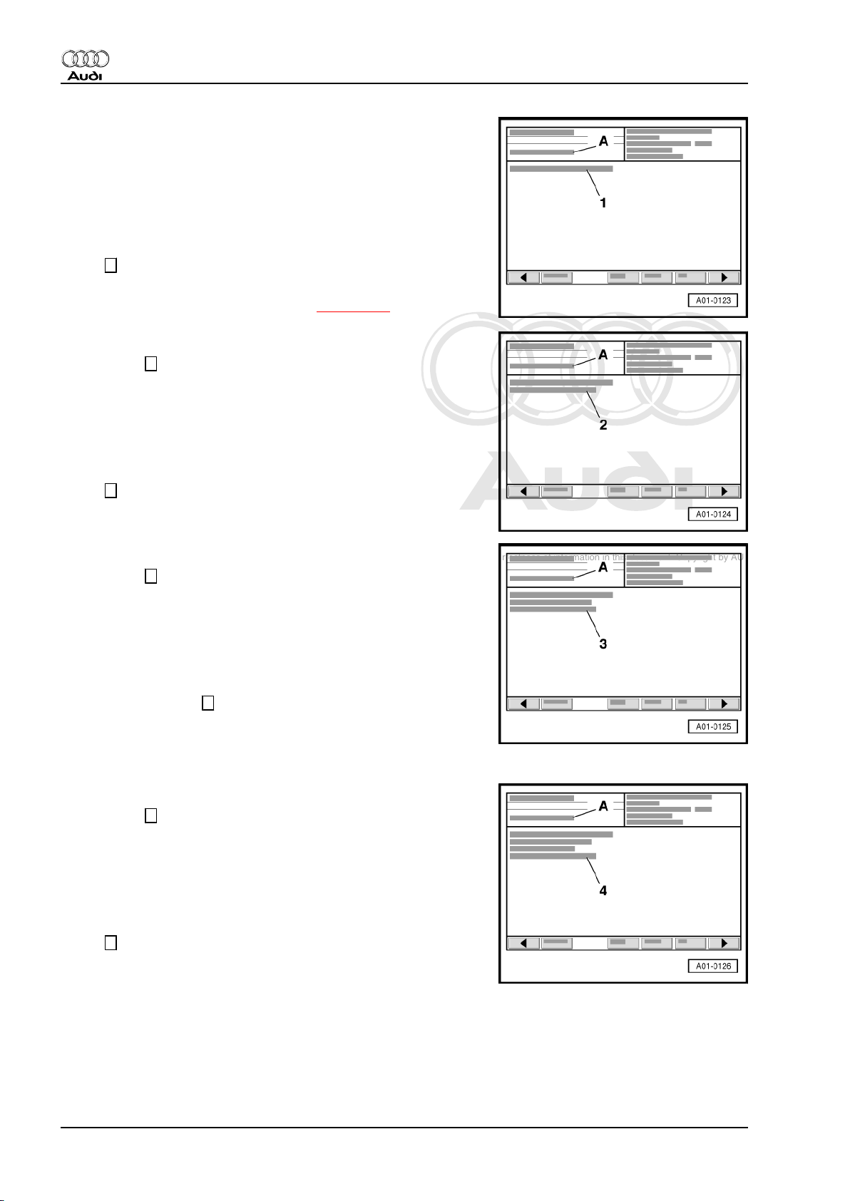
Activating solenoid valve 1 for activated charcoal filter -N80- (tank
breather valve)
Display on -VAS 5051 A- :
A - 1st control element in test
1 - Fuel tank breather valve -N80-
• The valve is activated (clicks) intermittently for 1 minute unless
the next control element is selected beforehand by touching
the → key.
If the valve is not activated (does not click), check activated char‐
coal filter system solenoid valve 1 -N80- ⇒ page 105 .
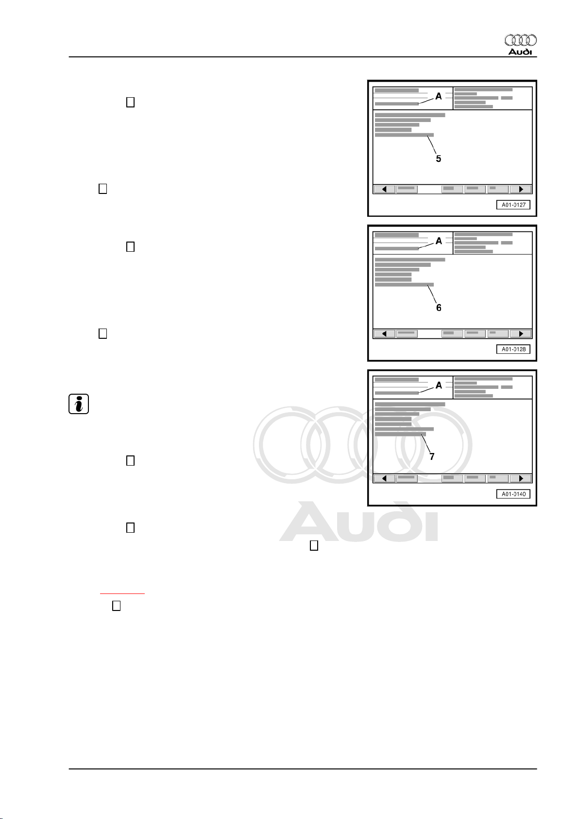
Activating secondary air inlet valve -N112-
– Press the → key.
Display on -VAS 5051 A- :
A - 2nd control element in test
2 - Secondary air inlet valve -N112-
• The valve is activated (clicks) intermittently for 1 minute unless
the next control element is selected beforehand by touching
the → key.
If the valve is not activated (does not click) ⇒ Rep. Gr. 26 .
Activating secondary air pump relay -J299-
– Press the → key.
Display on -VAS 5051 A- :
A - 3rd control element in test
3 - Secondary air pump relay -J299-
• The secondary air pump relay -J299- switches the secondary
air pump motor -V101- on and off intermittently for about 1
minute, or until the → key is pressed to advance the pro‐
gramme to the next control element.
If the motor is not activated (does not run intermittently), check
secondary air pump relay -J299- ⇒ Rep. Gr. 26 .
Activating charge pressure control solenoid valve -N75-
– Press the → key.
Display on -VAS 5051 A- :
A - 4th control element in test
4 - Solenoid valve for charge pressure control -N75-
• The valve is activated (clicks) intermittently for 1 minute unless
the next control element is selected beforehand by touching
the → key.
If the valve is not activated (does not click) ⇒ Rep. Gr. 21 .
24 Rep. Gr.01 - Self-diagnosis
Page 29
Protected by copyright. Copying for private or commercial purposes, in part or in whole, is not
permitted unless authorised by AUDI AG. AUDI AG does not guarantee or accept any liability
with respect to the correctness of information in this document. Copyright by AUDI AG.
Motronic injection and ignition system (4-cylinder) - Edition 05.2005
Activating inlet camshaft control valve 1 -N205-
– Press the → key.
Display on -VAS 5051 A- :
A - 5th control element in test
5 - Variable valve timing
• The valve is activated (clicks) intermittently for 1 minute unless
the next control element is selected beforehand by touching
the → key.
If the valve is not activated (does not click) ⇒ Rep. Gr. 15 .
Activating turbocharger air recirculation valve -N249-
– Press the → key.
Display on -VAS 5051 A- :
A - 6th control element in test
6 - Turbocharger air recirculation valve -N249-
• The valve is activated (clicks) intermittently for 1 minute unless
the next control element is selected beforehand by touching
the → key.
Audi TT 1999 ➤
If the valve is not activated (does not click) ⇒ Rep. Gr. 21 .
Activating injectors
Note
The injectors are activated in firing order sequence: Cyl. 1, Cyl.
3, Cyl. 4, Cyl. 2.
– Press the → key.
Display on -VAS 5051 A- :
A - 7th control element in test
7 - Injector, cylinder 1 -N30-
– Press the → key.
• The injector should click 5 times when you press the → key.
– All injectors are checked consecutively in this manner.
If one of the injectors is not activated (does not click), check in‐
jectors ⇒ page 70 .
– Touch → key following activation of last injector (cylinder 2).
3. Final control diagnosis 25
Page 30
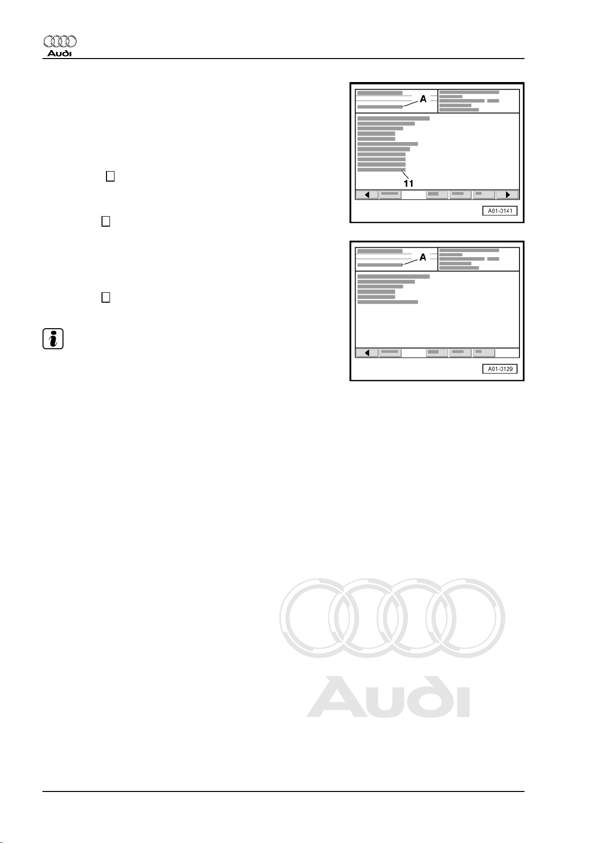
Protected by copyright. Copying for private or commercial purposes, in part or in whole, is not
permitted unless authorised by AUDI AG. AUDI AG does not guarantee or accept any liability
with respect to the correctness of information in this document. Copyright by AUDI AG.
Audi TT 1999 ➤
Motronic injection and ignition system (4-cylinder) - Edition 05.2005
Activating brake vacuum pump - only for vehicles with automatic
gearbox
Display on -VAS 5051 A- :
A - 11th control element in test
11 - Brake vacuum pump
• The electrical vacuum pump is activated for about 10 seconds
or until the → key is pressed to terminate the final control di‐
agnosis.
If the pump is not activated ⇒ Rep. Gr. 47 .
– Press the → key.
All models:
Display on -VAS 5051 A- :
A - Control element test is ended
– Press the ← key to exit from function “03 - Final control diag‐
nosis”.
Note
To repeat final control diagnosis, the engine must be started and
the ignition switched off and on again.
26 Rep. Gr.01 - Self-diagnosis
Page 31

Protected by copyright. Copying for private or commercial purposes, in part or in whole, is not
permitted unless authorised by AUDI AG. AUDI AG does not guarantee or accept any liability
with respect to the correctness of information in this document. Copyright by AUDI AG.
Motronic injection and ignition system (4-cylinder) - Edition 05.2005
4 Basic setting
The following operations can be performed using diagnosis func‐
tion “04 - Basic setting” with the engine stopped and the ignition
switched on:
♦ Adaption of throttle valve module to engine control unit in “dis‐
play group 060” ( ⇒ page 110 ).
♦ Vehicles with automatic gearbox: Adapting kickdown function
of accelerator position sender to engine control unit in “display
group 063” ( ⇒ page 119 ).
The following operation can be implemented with diagnosis func‐
tion “04 - Basic setting” with the engine running:
♦ Adaption process for Lambda control ⇒ page 88
Requirements for basic setting with the engine running
• No faults stored in fault memory.
• Coolant temperature at least 80 °C.
• Electrical equipment switched off (radiator fan must not run
during the test).
• Air conditioner switched off.
• Vehicles with automatic gearbox: selector lever in position “P”
or “N”
Procedure
– Connect vehicle diagnostic, testing and information system -
VAS 5051 A- ⇒ page 2 and select vehicle system “01 - Engine
electronics” from list. Depending on the desired operation, the
ignition must be switched on or the engine must be idling.
Display on -VAS 5051 A- :
– From list -1- select diagnostic function “04 - Basic setting”.
Audi TT 1999 ➤
Display on -VAS 5051 A- :
1 - Enter display group (highest possible entry = 255)
– Use keypad -2- to enter relevant display group number and
confirm entry by pressing the Q key.
Example:
– Enter “0” for “display group 000” and confirm by touching Q
key.
Note
After selecting “display group 000”, the activated charcoal filter
system solenoid valve 1 -N80- is closed and the air conditioner
compressor switched off.
4. Basic setting 27
Page 32

Protected by copyright. Copying for private or commercial purposes, in part or in whole, is not
permitted unless authorised by AUDI AG. AUDI AG does not guarantee or accept any liability
with respect to the correctness of information in this document. Copyright by AUDI AG.
Audi TT 1999 ➤
Motronic injection and ignition system (4-cylinder) - Edition 05.2005
Display on -VAS 5051 A- :
Display zones 1 2 3 4 5 6 7 8 9 10
Display group 000 (decimal readouts)
• Engine idling (coolant temperature at least 80 °C)
1 2 3 4 5 6 7 8 9 10 ← Display zones Specification Corresponds to
Learnt value for mixture forma‐
103…153 –10…10%
tion at part throttle
Learnt value for mixture formation at
78…178 –10…10%
idling speed
Throttle valve angle 1...10 0.4…4.0%
Voltage of on-board electrical system 142…206 10 … 14.5 V
Engine speed
• Vehicles with manual gearbox 70…84 700 ... 840 rpm
• Vehicles with automatic gearbox 64…76 640 ... 760 rpm
Control value for mixture formation 115…141 –10…10%
Learnt value for torque loss at idling speed 113…143 –3…3%
Torque at idling speed 106…189 –4.3…12.2%
Engine load (without electrical consumers) 14…39 10…30%
Coolant temperature (requirement for basic setting) 180…210 80 … 110 °C
Note
Where necessary, the values displayed are evaluated in the rel‐
evant sections.
– End function “04 - Basic setting” by pressing the ← key.
28 Rep. Gr.01 - Self-diagnosis
Page 33

Protected by copyright. Copying for private or commercial purposes, in part or in whole, is not
permitted unless authorised by AUDI AG. AUDI AG does not guarantee or accept any liability
with respect to the correctness of information in this document. Copyright by AUDI AG.
Motronic injection and ignition system (4-cylinder) - Edition 05.2005
5 Erasing fault memory
Note
If fault memory cannot be erased, interrogate fault memory again
and eliminate fault.
Conditions
• Fault memory interrogated ⇒ page 6 .
• All faults eliminated.
After interrogation of fault memory:
Display on -VAS 5051 A- :
– From list -1-, select function “05 - Erase fault memory”.
Audi TT 1999 ➤
Display on -VAS 5051 A- :
1 - No display (prior to erasing) or
- Fault memory erased
Note
If the following message appears in display zone -1-: “Fault mem‐
ory not yet interrogated”, this indicates failure to comply exactly
with the correct procedure. The fault memory can only be erased
after it has been interrogated.
2 - Note: Is function to be implemented? Note: Data will be erased!
– Touch OK key in display -2-.
– Terminate function “05 - Erase fault memory” by touching ←
key.
5. Erasing fault memory 29
Page 34

Protected by copyright. Copying for private or commercial purposes, in part or in whole, is not
permitted unless authorised by AUDI AG. AUDI AG does not guarantee or accept any liability
with respect to the correctness of information in this document. Copyright by AUDI AG.
Audi TT 1999 ➤
Motronic injection and ignition system (4-cylinder) - Edition 05.2005
6 Ending output
Display on -VAS 5051 A- :
– Select function “06 - End output” from the menu -1-.
Display on -VAS 5051 A- :
– Switch off ignition and unplug diagnostic connector when this
display appears.
30 Rep. Gr.01 - Self-diagnosis
Page 35

Protected by copyright. Copying for private or commercial purposes, in part or in whole, is not
permitted unless authorised by AUDI AG. AUDI AG does not guarantee or accept any liability
with respect to the correctness of information in this document. Copyright by AUDI AG.
Motronic injection and ignition system (4-cylinder) - Edition 05.2005
7 Coding control unit
– Connect vehicle diagnostic, testing and information system -
VAS 5051 A- ⇒ page 2 and select vehicle system “01 - Engine
electronics” from list. When doing this the ignition must be
switched on.
Display on -VAS 5051 A- :
– From list -1-, select diagnosis function “07 - Code control unit”.
Display on -VAS 5051 A- :
1 - Enter code word (highest possible entry = 32767)
Meaning of coding
XXX X X ← 5-position code number
Audi TT 1999 ➤
Vehicle type
Gearbox
Drive layout / extra functions
Country-specific version / emissions standard
Coding table
Country-specific version /
05
EU3 (emission standard)
emissions standard
Drive layout / extra functions
Gearbox
Vehicle type
11
0
2
5
7
0
1
5
0 Audi TT
EU4 (emission standard)
Front-wheel drive without traction control system / ESP
Four-wheel drive without traction control system
Front-wheel drive with traction control system / ESP
Four-wheel drive with Electronic Stability Program
5-speed manual gearbox
6-speed manual gearbox
Automatic gearbox (5-speed)
– Use keypad -2- to enter control unit code as per encoding ta‐
ble.
Example of coding
11500 EU4 (emission standard), front-wheel drive with TCS/
ESP, 5-speed manual gearbox, Audi TT
– Confirm entry by touching Q key.
Display on -VAS 5051 A- :
1 - The coding is being carried out
– Wait until next readout appears in the display.
7. Coding control unit 31
Page 36

Protected by copyright. Copying for private or commercial purposes, in part or in whole, is not
permitted unless authorised by AUDI AG. AUDI AG does not guarantee or accept any liability
with respect to the correctness of information in this document. Copyright by AUDI AG.
Audi TT 1999 ➤
Motronic injection and ignition system (4-cylinder) - Edition 05.2005
Display on -VAS 5051 A- :
1 - Vehicle system coding completed
2 - Control unit identification with new code
- (old code in brackets)
– Terminate function “07 - Code control unit” by touching ← key.
32 Rep. Gr.01 - Self-diagnosis
Page 37

Protected by copyright. Copying for private or commercial purposes, in part or in whole, is not
permitted unless authorised by AUDI AG. AUDI AG does not guarantee or accept any liability
with respect to the correctness of information in this document. Copyright by AUDI AG.
Motronic injection and ignition system (4-cylinder) - Edition 05.2005
8 Reading measured value block
Procedure
• Coolant temperature at least 80 °C.
• Electrical equipment switched off (radiator fan must not run
during the test).
• Air conditioner switched off.
– Connect vehicle diagnostic, testing and information system -
VAS 5051 A- ⇒ page 2 and select vehicle system “01 - Engine
electronics”. For this purpose, the ignition must be switched
on or the engine must be running at idling speed.
Display on -VAS 5051 A- :
– From the list -1- select diagnostic function “08 - Read meas‐
ured value block”.
Audi TT 1999 ➤
Display on -VAS 5051 A- :
1 - Enter display group (highest possible entry = 255)
– Use keypad -2- to enter relevant “display group number” and
confirm entry by pressing the Q key.
Note
The display group to be selected is indicated in the test proce‐
dures for the relevant functions and components.
Display on -VAS 5051 A- for display group 000:
Display zones 1 2 3 4 5 6 7 8 9 10
8. Reading measured value block 33
Page 38

Protected by copyright. Copying for private or commercial purposes, in part or in whole, is not
permitted unless authorised by AUDI AG. AUDI AG does not guarantee or accept any liability
with respect to the correctness of information in this document. Copyright by AUDI AG.
Audi TT 1999 ➤
Motronic injection and ignition system (4-cylinder) - Edition 05.2005
Display on -VAS 5051 A- for display groups 001 ... 255:
1 - Display zones 1 ... 4. If a display zone is not assigned, there
is no display on this line.
2 - The display group selected is shown here
3 - Touching these keys permits switching to a different display
group.
4 - Touching these keys permits switching to a different function
(e.g. from “Reading measured value block” to “Basic setting”
and vice versa).
– Press the ← key to exit from the function “08 - Read measured
value block”.
34 Rep. Gr.01 - Self-diagnosis
Page 39

Protected by copyright. Copying for private or commercial purposes, in part or in whole, is not
permitted unless authorised by AUDI AG. AUDI AG does not guarantee or accept any liability
with respect to the correctness of information in this document. Copyright by AUDI AG.
Motronic injection and ignition system (4-cylinder) - Edition 05.2005
9 Readiness code
♦ The readiness code appears as an 8-position display in
“Measured value block 086”, display zone 1. Each of the 8
positions is assigned to a particular emission-related system.
♦ When a test series has to be implemented in full, the self-di‐
agnosis checks the operation of each of these systems and
sets the corresponding position in the 8-position display from
“1” to “0” following successful completion of the test.
♦ If the readiness code was generated following successful
completion of a test series, it will be “00000000” (measured
value block 086, display zone 1).
♦ If an individual test is implemented in full but is “not OK”, an
entry is made in the fault memory. Interrogate fault memory
⇒ page 6 .
The readiness code is reset to “01101101” in the following cases:
♦ The fault memory has been erased,
♦ The power supply to the engine control unit has been inter‐
rupted (e.g. multi-pin connectors unplugged, battery discon‐
nected),
♦ A new engine control unit is installed.
In this case, the readiness code must be generated again
⇒ page 37 .
Audi TT 1999 ➤
Note
The emission-related tests are implemented by the control unit
whilst driving under various load conditions, and the readiness
code is generated automatically. In such cases, however, there
is no provision for performing a final check; in other words there
is no visible confirmation that the vehicle is in perfect working or‐
der when handed over to the customer.
9.1 Reading out readiness code
– Connect vehicle diagnostic, testing and information system -
VAS 5051 A- ⇒ page 2 and select vehicle system “01 - Engine
electronics” from list. Engine must be idling.
Display on -VAS 5051 A- :
– From the list -1- select diagnostic function “08 - Read meas‐
ured value block”.
9. Readiness code 35
Page 40

Protected by copyright. Copying for private or commercial purposes, in part or in whole, is not
permitted unless authorised by AUDI AG. AUDI AG does not guarantee or accept any liability
with respect to the correctness of information in this document. Copyright by AUDI AG.
Audi TT 1999 ➤
Motronic injection and ignition system (4-cylinder) - Edition 05.2005
Display on -VAS 5051 A- :
1 - Enter display group (highest possible entry = 255)
– Use keypad -2- to enter “86” for “Display group number 086”
and confirm by touching the Q key.
Display on -VAS 5051 A- :
– Check readiness code in display zone -1-.
• Specification: 00000000
Display group 086: Readiness code
Display
zone
1 00000000 Ready bits
2 XXXXXXXX Individual tests per‐
Indicated on display Display shows Range Specification
Tests completed
1 = Not completed 00000000
0 = Completed
1 = Not completed
formed
3 XXXXXXXX Individual tests per‐
0 = Completed
1 = Not completed
formed
0 = Completed
Note
Display zone 1 is of primary importance. This display indicates
which system has been checked by the self-diagnosis since the
fault memory was last erased or since installation of a new control
unit. After the fault memory has been erased, all values which can
be checked are set to “1”. On successful completion of a test, the
values are set to “0”.
Explanatory notes on displays in display group 086, display zone 1
1 2 3 4 5 6 7 8 ← Display position
Catalytic converter diagnosis
♦ Readout 0 = Test performed
♦ Display 1 = Test not performed (generating readiness code ⇒ page 37 )
36 Rep. Gr.01 - Self-diagnosis
Display always reads 0
Page 41

Protected by copyright. Copying for private or commercial purposes, in part or in whole, is not
permitted unless authorised by AUDI AG. AUDI AG does not guarantee or accept any liability
with respect to the correctness of information in this document. Copyright by AUDI AG.
Motronic injection and ignition system (4-cylinder) - Edition 05.2005
Explanatory notes on displays in display group 086, display zone 1
Activated charcoal filter system
♦ Readout 0 = Test performed
♦ Display 1 = Test not performed (generating readiness code ⇒ page 37 )
Audi TT 1999 ➤
Secondary air system
♦ Readout 0 = Test performed
♦ Display 1 = Test not performed (generating readiness code ⇒ page 37 )
Display always reads 0
Lambda probes
♦ Readout 0 = Test performed
♦ Display 1 = Test not performed (generating readiness code ⇒ page 37 )
Lambda probe heating
♦ Readout 0 = Test performed
♦ Display 1 = Test not performed (generating readiness code ⇒ page 37 )
Display always reads 0
Note
The readiness code is only generated if all display positions in
zone 1 are set to “0”.
If the reading in display zone 1 matches the specification
“00000000”:
– Press the ← key.
– Interrogate the fault memory as a check ⇒ page 6 (there
should not be any faults stored).
If specification is not obtained:
– Generate readiness code ⇒ page 37 .
9.2 Generating readiness code
Special tools and workshop equipment required
♦ Engine speed adjuster -V.A.G 1788/10-
Conditions
• Vehicle is stationary.
• Electrical equipment switched off (radiator fan must not run
during the test).
9. Readiness code 37
Page 42

Protected by copyright. Copying for private or commercial purposes, in part or in whole, is not
permitted unless authorised by AUDI AG. AUDI AG does not guarantee or accept any liability
with respect to the correctness of information in this document. Copyright by AUDI AG.
Audi TT 1999 ➤
Motronic injection and ignition system (4-cylinder) - Edition 05.2005
• Air conditioner switched off.
• Coolant temperature at least 80 °C ⇒ Measured value block
004, display zone 3. Important: Warm up engine if possible by
means of a test drive.
• Handbrake applied.
• Vehicles with automatic gearbox: selector lever in position “P”
or “N”
Note
If, within a given step, “OK” is immediately displayed as the test
result following selection of a display group, the test has already
been implemented and it is possible to proceed with the next step.
Work step 1: Interrogating fault memory
• Engine stopped, ignition switched on
– Connect vehicle diagnostic, testing and information system -
VAS 5051 A- ⇒ page 2 and select vehicle system “01 - Engine
electronics” from list. When doing this the ignition must be
switched on.
Display on -VAS 5051 A- :
– From list -1-, select diagnosis function “02 - Interrogate fault
memory”.
Display on -VAS 5051 A- :
-1- Content of fault memory No faults detected
or
X faults detected
-2- Fault Fault code
Fault location
Type of fault
If a fault has been stored:
– Eliminate fault, erase fault memory. Perform test drive and in‐
terrogate fault memory again as a check.
If there are no faults stored:
– Press the ← key.
38 Rep. Gr.01 - Self-diagnosis
Page 43

Protected by copyright. Copying for private or commercial purposes, in part or in whole, is not
permitted unless authorised by AUDI AG. AUDI AG does not guarantee or accept any liability
with respect to the correctness of information in this document. Copyright by AUDI AG.
Motronic injection and ignition system (4-cylinder) - Edition 05.2005
Work step 2: Erasing fault memory
• Engine stopped, ignition switched on
Display on -VAS 5051 A- :
– From list -1-, select diagnostic function “05 - Erase fault mem‐
ory”.
Note
The readiness code is reset on erasing the fault memory and must
therefore be generated again.
Display on -VAS 5051 A- :
1 - No display (prior to erasing) or
- Fault memory erased
2 - Note: Is function to be implemented? Note: Data will be erased!
– Touch OK key in display -2-.
– Press the ← key.
Audi TT 1999 ➤
Work step 3: Adapting throttle valve module to engine control unit
• Engine stopped, ignition switched on
Display on -VAS 5051 A- :
– From list -1- select diagnostic function “04 - Basic setting”.
Display on -VAS 5051 A- :
1 - Enter display group (highest possible entry = 255)
– Use keypad -2- to enter “60” for “Display group number 060”
and confirm by touching the Q key.
9. Readiness code 39
Page 44

Protected by copyright. Copying for private or commercial purposes, in part or in whole, is not
permitted unless authorised by AUDI AG. AUDI AG does not guarantee or accept any liability
with respect to the correctness of information in this document. Copyright by AUDI AG.
Audi TT 1999 ➤
Motronic injection and ignition system (4-cylinder) - Edition 05.2005
Display on -VAS 5051 A- :
– Check displays in zones -3- and -4-.
Display group 060: Adaption of throttle valve module
Display
Indicated on display Display shows Range Specification
zone
3 X Adaption step counter
4 XXXXXXXXXX Adaption status ADP. runs
0…8
1)
8
ADP O.K.
ADP OK
ERROR
1)
•
The numbers represent the corresponding adaption status. Following adaption, the adaption step
counter reaches the number 8 (numbers may also be skipped). It is important that the specification
“ADP OK” is displayed in zone 4 after adaption. The behaviour of the adaption step counter (display
zone 3) during adaption is not critical.
If “ERROR” is displayed:
– Interrogate fault memory ⇒ page 38 .
If specified value “ADP. OK” is attained:
– Perform next step.
Work step 4: Adapting kick-down function - only for vehicles with
automatic gearbox
• Engine stopped, ignition switched on
– To switch to “display group 063”, touch ↑ key 3 times.
Display on -VAS 5051 A- :
Note
User is then prompted to “operate kickdown”.
– Fully depress accelerator pedal beyond kickdown point and
keep it pressed.
– Check displays in zones -3- and -4-.
Display group 063: Adapting kickdown function
Display
Indicated on display Display shows Range Specification
zone
3 XXXXXXXXXX
4 XXXXXXXXXX Adaption status Operate
ADP runs
ADP OK
ERROR
Kickdown
ADP O.K.
1)
2)
40 Rep. Gr.01 - Self-diagnosis
Page 45

Protected by copyright. Copying for private or commercial purposes, in part or in whole, is not
permitted unless authorised by AUDI AG. AUDI AG does not guarantee or accept any liability
with respect to the correctness of information in this document. Copyright by AUDI AG.
Audi TT 1999 ➤
Motronic injection and ignition system (4-cylinder) - Edition 05.2005
Display group 063: Adapting kickdown function
Display
Indicated on display Display shows Range Specification
zone
1)
•
The abbreviation “ADP” stands for “Adaption”.
2)
•
“ERROR” is indicated, for example, if the accelerator pedal is not pressed immediately after requested
by the tester or if the pedal is released before the adaption process is finished. In both cases, exit
function “04 - Basic setting” by pressing the ←
key and restart adaption.
If specified value “kickdown ADP OK” is attained:
Work step 5: Checking operating status of Lambda control
– Start engine.
Note
After starting the engine, it may be necessary to select vehicle
system “01 - Engine electronics” and diagnosis function “04 - Ba‐
sic setting” again.
– Fit engine speed adjuster -V.A.G 1788/10- at accelerator ped‐
al and increase engine speed to 2000 rpm.
• Engine running at 2000 rpm
Display on -VAS 5051 A- :
– Press the ← key.
Display on -VAS 5051 A- :
1 - Enter display group (highest possible entry = 255)
– Use keypad -2- to enter “30” for “Display group number 030”
and confirm by touching the Q key.
9. Readiness code 41
Page 46

Protected by copyright. Copying for private or commercial purposes, in part or in whole, is not
permitted unless authorised by AUDI AG. AUDI AG does not guarantee or accept any liability
with respect to the correctness of information in this document. Copyright by AUDI AG.
Audi TT 1999 ➤
Motronic injection and ignition system (4-cylinder) - Edition 05.2005
Display on -VAS 5051 A- :
– Check displays in zones -1- and -2-.
Note
It may take several minutes to obtain result of diagnosis.
Display group 030: Lambda probe status
Display
Indicated on display Display shows Range Specification
zone
1 XXX Lambda probe status
bank 1, probe 1
2 XXX Lambda probe status
bank 1, probe 2
0 = off
1 = on
0 = off
1 = on
111
110
Explanatory notes on 3-position display in display group 030, display zone 1 and 2
1 2 3 ← Display position
•
•
Lambda control: 0 = not active; 1 = active
Lambda probe condition: 0 = not active; 1 = active
Lambda probe heating condition: 0 = not active; 1 = active
1)
Lambda control of the Lambda probe after catalytic converter (bank 1, probe 2) is not active without
engine load, in other words the 3rd digit of the 3-digit display is “0”.
2)
The display (heating) fluctuates at certain operating points between “0” and “1”.
1)
2)
– Do not continue with testing until the displays have reached
“111” in display zone 1 and “110” in display zone 2 at least
once.
Work step 6: Diagnosis of ageing of Lambda probe before cata‐
lytic converter
• Engine still running at 2000 rpm.
Display on -VAS 5051 A- :
– To switch to “display group 034”, touch ↑ key 4 times.
– Check display in zone -4-.
Note
It may take several minutes to obtain result of diagnosis.
42 Rep. Gr.01 - Self-diagnosis
Page 47

Protected by copyright. Copying for private or commercial purposes, in part or in whole, is not
permitted unless authorised by AUDI AG. AUDI AG does not guarantee or accept any liability
with respect to the correctness of information in this document. Copyright by AUDI AG.
Motronic injection and ignition system (4-cylinder) - Edition 05.2005
Display group 034: Diagnosis of ageing of Lambda probe before catalytic converter (bank 1)
Display
Indicated on display Display shows Range Specification
zone
4 XXXXXXXXXX Diagnosis status Test OFF
B1-P1 n.OK
If display shows “B1-P1 n.OK”:
– Interrogate fault memory ⇒ page 38 .
If reading matches specification “B1-P1 OK”:
– Perform next step.
Work step 7: Diagnosis of condition of Lambda probe after cata‐
lytic converter
• Engine still running at 2000 rpm.
Display on -VAS 5051 A- :
– To switch to “display group 036”, touch ↑ key 2 times.
Audi TT 1999 ➤
B1-P1 OK
Test ON
B1-P1 OK
– Check display in zone -2-.
Display group 036: Condition of Lambda probe after catalytic converter (bank 1)
Display
Indicated on display Display shows Range Specification
zone
2 XXXXXXXXXX Diagnosis status Test OFF
B1-P2 n.OK
If “B1-P2 n.OK” is displayed:
– Interrogate fault memory ⇒ page 38 .
If reading matches specification “B1-P2 OK”:
– Perform next step.
Work step 8: Diagnosis of Lambda control system
• Engine still running at 2000 rpm.
Display on -VAS 5051 A- :
– To switch to “display group 037”, touch ↑ key.
B1-P2 OK
Test ON
B1-P2 OK
– Check display in zone -4-.
9. Readiness code 43
Page 48

Protected by copyright. Copying for private or commercial purposes, in part or in whole, is not
permitted unless authorised by AUDI AG. AUDI AG does not guarantee or accept any liability
with respect to the correctness of information in this document. Copyright by AUDI AG.
Audi TT 1999 ➤
Motronic injection and ignition system (4-cylinder) - Edition 05.2005
Display group 037: Diagnosis of Lambda control system (bank 1)
Display
Indicated on display Display shows Range Specification
zone
4 XXXXXXXXXX Diagnosis status Test OFF
Syst. n. OK
If “Syst. n.OK” is displayed:
– Interrogate fault memory ⇒ page 38 .
If specified value “Syst. OK” is attained:
– Perform next step.
Work step 9: Diagnosis of ageing of Lambda probe after catalytic
converter
• Engine still running at 2000 rpm.
Display on -VAS 5051 A- :
– Press the ← key.
Syst. OK
Test ON
Syst. OK
Display on -VAS 5051 A- :
1 - Enter display group (highest possible entry = 255)
– Use keypad -2- to enter “43” for “Display group number 043”
and confirm by touching the Q key.
Display on -VAS 5051 A- :
– Check display in zone -4-.
44 Rep. Gr.01 - Self-diagnosis
Page 49

Protected by copyright. Copying for private or commercial purposes, in part or in whole, is not
permitted unless authorised by AUDI AG. AUDI AG does not guarantee or accept any liability
with respect to the correctness of information in this document. Copyright by AUDI AG.
Motronic injection and ignition system (4-cylinder) - Edition 05.2005
Display group 043: Diagnosis of ageing of Lambda probe after catalytic converter (bank 1)
Display
Indicated on display Display shows Range Specification
zone
4 XXXXXXXXXX Diagnosis status Test OFF
B1-P2 n.OK
If “B1-P2 n.OK” is displayed:
– Interrogate fault memory ⇒ page 38 .
If reading matches specification “B1-P2 OK”:
– Perform next step.
Work step 10: Diagnosis of catalytic converter
• Engine still running at 2000 rpm.
Display on -VAS 5051 A- :
– To switch to “display group 046”, touch ↑ key 3 times.
Audi TT 1999 ➤
B1-P2 OK
Test ON
B1-P2 OK
– Check displays in zones -2- and -4-.
Note
The test duration for catalytic converter diagnosis is approximate‐
ly 60 seconds.
Display group 046: Diagnosis of catalytic converter (bank 1)
Display
Indicated on display Display shows Range Specification
zone
2 XXX °C Exhaust gas tempera‐
Above 320 °C
ture
4 XXXXXXXXXX Diagnosis status Test OFF
Cat B1 OK
Test ON
CAT B1 OK
CAT B1 n.OK
1)
•
The test will not be started if the exhaust gas temperature is not within the specified range. Increase
or reduce engine speed if necessary.
If “CAT B1 n.OK” is displayed:
– Interrogate fault memory ⇒ page 38 . If no fault has been stor‐
ed, renew catalytic converter.
If reading matches specification “CAT B1 OK”:
– Perform next step.
1)
9. Readiness code 45
Page 50

Protected by copyright. Copying for private or commercial purposes, in part or in whole, is not
permitted unless authorised by AUDI AG. AUDI AG does not guarantee or accept any liability
with respect to the correctness of information in this document. Copyright by AUDI AG.
Audi TT 1999 ➤
Motronic injection and ignition system (4-cylinder) - Edition 05.2005
Work step 11: Diagnosis of fuel tank breather valve
– Remove engine speed adjuster -V.A.G 1788/10- and leave
engine idling.
• Engine running at idling speed.
Display on -VAS 5051 A- :
– Press the ← key.
Display on -VAS 5051 A- :
1 - Enter display group (highest possible entry = 255)
– Use keypad -2- to enter “70” for “Display group number 070”
and confirm by touching the Q key.
Display on -VAS 5051 A- :
– Check display in zone -4-.
Note
If the test is not started or if the display switches from “Test ON”
to “Test OFF”, give a brief burst of throttle and the test will be
repeated.
Display group 070: Diagnosis of fuel tank breather valve
Display
Indicated on display Display shows Range Specification
zone
4 XXXXXXXXXX Diagnosis status Test OFF
TBV n.OK
If “TBV n.OK” is displayed:
– Interrogate fault memory ⇒ page 38 . Check activated charcoal
filter system solenoid valve 1 -N80- ⇒ page 105 .
If specified value “TBV. OK” is attained:
– Perform next step.
TBV OK
Test ON
TBV OK
Abort
46 Rep. Gr.01 - Self-diagnosis
Page 51

Protected by copyright. Copying for private or commercial purposes, in part or in whole, is not
permitted unless authorised by AUDI AG. AUDI AG does not guarantee or accept any liability
with respect to the correctness of information in this document. Copyright by AUDI AG.
Motronic injection and ignition system (4-cylinder) - Edition 05.2005
Work step 12: Diagnosis of secondary air system
• Engine running at idling speed.
– Press the ← key.
Display on -VAS 5051 A- :
1 - Enter display group (highest possible entry = 255)
– Use keypad -2- to enter “77” for “Display group number 077”
and confirm by touching the Q key.
Display on -VAS 5051 A- :
– Check display in zone -4-.
Audi TT 1999 ➤
Display group 077: Diagnosis of secondary air system (bank 1)
Display
zone
4 XXXXXXXXXX Diagnosis status Test OFF
Indicated on display Display shows Range Specification
Syst. n. OK
If “Syst. n.OK” is displayed:
– Interrogate fault memory ⇒ page 38 . Check secondary air
system ⇒ Rep. Gr. 26 .
If specified value “Syst. OK” is attained:
– Press the ← key.
Work step 13: Reading out readiness code
– Read out readiness code ⇒ page 35 .
Syst. OK
Test ON
Syst. OK
9. Readiness code 47
Page 52

Protected by copyright. Copying for private or commercial purposes, in part or in whole, is not
permitted unless authorised by AUDI AG. AUDI AG does not guarantee or accept any liability
with respect to the correctness of information in this document. Copyright by AUDI AG.
Audi TT 1999 ➤
Motronic injection and ignition system (4-cylinder) - Edition 05.2005
24 – Mixture preparation - injection
1 Servicing Motronic injection system
Note
Certain tests may lead to a fault being detected by the control unit
and stored in the memory. The fault memory must therefore be
interrogated and if necessary erased on completion of all tests
and repair work. The readiness code must then be generated af‐
ter erasing the fault memory ⇒ page 37 .
1.1 Safety precautions
Note the following if testers and measuring instruments have to
be used during a road test:
WARNING
♦ To avoid any risk of accident, observe the following pre‐
cautions when using test instruments while road testing
the vehicle:
Audi TT Coupé:
♦ To read measured value blocks, use only the vehicle di‐
agnostic, testing and information system -VAS 5051 A- or
the vehicle diagnostic and information system VAS 5052- . Test equipment must always be secured on
the rear seat and operated from that position by a second
person.
♦ Due to the limited space, slide the front passenger's seat
forwards as far as it will go and (without pulling the release
lever) incline the backrest as far forwards as possible by
turning the adjuster knob. Do not operate the release lever
to tilt the backrest forward.
Audi TT Roadster:
♦ In the Audi TT Roadster, only use the vehicle diagnostic
and information system -VAS 5052- with the passenger's
airbag deactivated.
♦ Deactivate the front passenger's airbag by means of the
key switch in the glove box or via the self-diagnosis func‐
tion ⇒ Body, self-diagnosis; Rep. Gr. 01 .
♦ Reactivate front passenger's airbag on completion of
work.
Note the following to avoid possible injury and/or the destruction
of electrical and electronic components:
♦ Always switch off the ignition before connecting or discon‐
necting injection or ignition system wiring or tester cables.
♦ If the engine is to be operated at starter motor speed without
it starting (e.g. compression test), unplug the connectors at the
ignition coils and injectors.
♦ Always switch off ignition before washing engine.
♦ Always switch off the ignition before connecting or discon‐
necting the battery, otherwise the engine control unit may be
damaged.
48 Rep. Gr.24 - Mixture preparation - injection
Page 53

Protected by copyright. Copying for private or commercial purposes, in part or in whole, is not
permitted unless authorised by AUDI AG. AUDI AG does not guarantee or accept any liability
with respect to the correctness of information in this document. Copyright by AUDI AG.
Motronic injection and ignition system (4-cylinder) - Edition 05.2005
WARNING
The fuel system is pressurised. Wrap a cloth around the con‐
nection before opening the system. Then dissipate pressure
by carefully unfastening the connection.
1.2 Rules for cleanliness
When working on the fuel supply/injection system, pay careful at‐
tention to the following “6 rules”:
♦ Thoroughly clean all unions and surrounding areas before dis‐
connecting.
♦ Place parts that have been removed on a clean surface and
cover them over. Use only lint-free cloths.
♦ Carefully cover or seal open components if repairs cannot be
carried out immediately.
♦ Only install clean components; replacement parts should only
be unpacked immediately prior to installation. Do not use parts
that have been previously unpacked and stored away loose
(e.g. in toolboxes, etc.).
♦ When the system is open: Do not work with compressed air if
this can be avoided. Do not move the vehicle unless absolutely
necessary.
♦ Unplugged electrical connectors must be kept clean and dry.
Make sure connections are dry when attaching.
Audi TT 1999 ➤
1. Servicing Motronic injection system 49
Page 54

Protected by copyright. Copying for private or commercial purposes, in part or in whole, is not
permitted unless authorised by AUDI AG. AUDI AG does not guarantee or accept any liability
with respect to the correctness of information in this document. Copyright by AUDI AG.
Audi TT 1999 ➤
Motronic injection and ignition system (4-cylinder) - Edition 05.2005
1.3 Overview of fitting locations
1 - Lambda probe -G39- (be‐
fore catalytic converter) with
Lambda probe heater -Z19and Lambda probe after cata‐
lytic converter -G130- with
Lambda probe 1 heater (after
catalytic converter) -Z29-
❑ Fitting location of Lamb‐
da probes and protec‐
tive cover for connec‐
tors ⇒ page 53
❑ Identification of connec‐
tors for Lambda probes
⇒ page 53
❑ Lambda probe -G39-
(before catalytic con‐
verter): continuous-ac‐
tion Lambda probe
❑ Checking Lambda
probe and Lambda con‐
trol before catalytic con‐
verter ⇒ page 86
❑ Checking ageing of
Lambda probe before
catalytic converter
⇒ page 90
❑ Checking heating for
Lambda probe before
catalytic converter
⇒ page 93
❑ Checking Lambda
probe and Lambda con‐
trol after catalytic con‐
verter ⇒ page 95
❑ Checking heating for
Lambda probe after cat‐
alytic converter
⇒ page 101
❑ Removing and installing ⇒ page 103
2 - Hall sender -G163-
❑ Checking ⇒ page 170
3 - Injectors
❑ Cylinder 1 -N30❑ Cylinder 2 -N31❑ Cylinder 3 -N32❑ Cylinder 4 -N33❑ Checking ⇒ page 70
❑ Removing and installing ⇒ page 73
4 - Motronic control unit -J220-
❑ Checking voltage supply of engine control unit ⇒ page 165
❑ Procedure following interruption of voltage supply ⇒ page 59
❑ Removing and installing:
⇒ “1.9 Removing and installing engine control unit without protective housing”, page 59 or
⇒ “1.10 Removing and installing engine control unit with protective housing”, page 61
50 Rep. Gr.24 - Mixture preparation - injection
Page 55

Protected by copyright. Copying for private or commercial purposes, in part or in whole, is not
permitted unless authorised by AUDI AG. AUDI AG does not guarantee or accept any liability
with respect to the correctness of information in this document. Copyright by AUDI AG.
Motronic injection and ignition system (4-cylinder) - Edition 05.2005
5 - Ignition coils
❑ Cylinder 1 -N❑ Cylinder 2 -N128❑ Cylinder 3 -N158❑ Cylinder 4 -N163❑ Checking ⇒ page 149
6 - Solenoid valve for charge pressure control -N75-
❑ Checking ⇒ Rep. Gr. 21
7 - Accelerator position sender -G79- and accelerator position sender 2 -G185-
❑ Fitting location ⇒ page 53
❑ Checking ⇒ page 116
8 - Brake light switch -F- and brake pedal switch -F47-
❑ Fitting location ⇒ page 54
❑ Checking ⇒ page 121
9 - Clutch pedal switch -F36-
❑ Fitting location ⇒ page 54
❑ Checking ⇒ page 125
10 - Instrument cluster
❑ With exhaust emissions warning lamp -K83- (MIL lamp) ⇒ page 63
❑ With electronic power control fault lamp -K132- (EPC lamp) ⇒ page 108
11 - Motronic current supply relay -J271-
❑ Fitting location ⇒ page 55
❑ Checking ⇒ page 152
12 - Secondary air pump relay -J299-
❑ Fitting location ⇒ page 55
❑ Checking ⇒ Rep. Gr. 26
13 - Air mass meter -G70-
❑ Checking ⇒ page 80
14 - Coolant temperature sender -G62-
❑ Checking ⇒ page 162
❑ If necessary release pressure in cooling system before removing
15 - Inlet camshaft control valve 1 -N205-
❑ Checking ⇒ Rep. Gr. 15
16 - Fuel pressure regulator
❑ Checking ⇒ page 67
17 - Engine speed sender -G28-
❑ Checking ⇒ page 159
18 - Knock sensor 2 -G66-
❑ Checking ⇒ page 168
Audi TT 1999 ➤
19 - Turbocharger air recirculation valve -N249-
❑ Fitting location ⇒ page 52
❑ Checking ⇒ Rep. Gr. 21
20 - 3-pin electrical connector
❑ 3 x
❑ Fitting location ⇒ page 53
❑ For engine speed sender -G28- , knock sensor 1 -G61- , knock sensor 2 -G66-
1. Servicing Motronic injection system 51
Page 56

Protected by copyright. Copying for private or commercial purposes, in part or in whole, is not
permitted unless authorised by AUDI AG. AUDI AG does not guarantee or accept any liability
with respect to the correctness of information in this document. Copyright by AUDI AG.
Audi TT 1999 ➤
Motronic injection and ignition system (4-cylinder) - Edition 05.2005
21 - Secondary air inlet valve -N112-
❑ Fitting location ⇒ page 52
❑ Checking ⇒ Rep. Gr. 26
22 - Knock sensor 1 -G61-
❑ Checking ⇒ page 168
23 - Intake air temperature sender -G42-
❑ Checking ⇒ page 157
24 - Secondary air pump motor -V101-
❑ Checking ⇒ Rep. Gr. 26
25 - Power steering pressure switch -F88-
❑ Fitting location ⇒ page 54
26 - Throttle valve module -J338-
❑ Including throttle valve drive (electric throttle operation) -G186- , angle sender for throttle valve drive -
G187- and angle sender 2 for throttle valve drive -G188❑ Checking ⇒ page 109
❑ Perform adaption after renewal ⇒ page 110
27 - Activated charcoal filter solenoid valve 1 -N80-
❑ Checking ⇒ page 105
28 - Charge air pressure sender -G31-
❑ Screwed into top of charge air cooler
❑ Checking ⇒ Rep. Gr. 21
Air recirculation valve for turbocharger -N249- and secondary air
inlet valve -N112-
♦ Fitting location: below front bracket on intake manifold.
1 - Secondary air inlet valve -N112-
2 - Non-return valve
3 - To vacuum reservoir
4 - To mechanical air recirculation valve
5 - To combination valve for secondary air
6 - To connection on intake manifold
7 - Turbocharger air recirculation valve -N249-
52 Rep. Gr.24 - Mixture preparation - injection
Page 57

Protected by copyright. Copying for private or commercial purposes, in part or in whole, is not
permitted unless authorised by AUDI AG. AUDI AG does not guarantee or accept any liability
with respect to the correctness of information in this document. Copyright by AUDI AG.
Motronic injection and ignition system (4-cylinder) - Edition 05.2005
Accelerator position sender -G79- and accelerator position send‐
er 2 -G185-
♦ Fitting location: in accelerator pedal module -arrow-.
Note
Diagram shows set-up on left-hand drive vehicles.
Lambda probes and protective cover for connectors
1 - Lambda probe, before catalytic converter -G39- with Lamb‐
da probe heater -Z19-
2 - Protective cover for connectors
3 - Lambda probe, after catalytic converter -G130- with Lamb‐
da probe heater 1, after catalytic converter -Z29-
Audi TT 1999 ➤
Note
The connectors for the Lambda probes and Lambda probe heat‐
ing are accessible on the floor of the vehicle (right-side) after
unscrewing the protective cover -arrows-.
Identification of connectors
♦ Black connector for Lambda probe -G39- (before catalytic
converter) and Lambda probe heater -Z19- .
♦ Brown connector for Lambda probe after catalytic converter -
G130- and Lambda probe heater -Z29- .
3-pin connectors
1 - For knock sensor 1 -G61-
2 - For engine speed sender -G28-
3 - For knock sensor 2 -G66-
1. Servicing Motronic injection system 53
Page 58

Protected by copyright. Copying for private or commercial purposes, in part or in whole, is not
permitted unless authorised by AUDI AG. AUDI AG does not guarantee or accept any liability
with respect to the correctness of information in this document. Copyright by AUDI AG.
Audi TT 1999 ➤
Motronic injection and ignition system (4-cylinder) - Edition 05.2005
Brake light switch -F- and brake pedal switch -F47-
♦ Fitting location: on pedal bracket -arrow-.
Clutch pedal switch -F36-
♦ Fitting location: on pedal bracket -arrow-.
Power steering pressure switch -F88-
♦ Fitting location: on power steering pump -arrow-.
54 Rep. Gr.24 - Mixture preparation - injection
Page 59

Protected by copyright. Copying for private or commercial purposes, in part or in whole, is not
permitted unless authorised by AUDI AG. AUDI AG does not guarantee or accept any liability
with respect to the correctness of information in this document. Copyright by AUDI AG.
Motronic injection and ignition system (4-cylinder) - Edition 05.2005
Motronic current supply relay -J271- and secondary air pump re‐
lay -J299-
♦ Fitting location: Under cover on bulkhead (left-side).
1 - Motronic current supply relay -J271-
2 - Secondary air pump relay -J299-
Note
To remove the protective cover on vehicles with body brace, dis‐
engage and lower the relay holder at the bulkhead. If necessary
also unplug connector at air mass meter.
1.4 Dismantling and assembling air cleaner
1 - Hexagon bolt, 10 Nm
2 - Air cleaner housing (bottom
section)
3 - Hose
❑ To secondary air pump
4 - Seal
5 - Air mass meter -G70-
❑ Removing and installing
⇒ page 57
6 - Cross-head screw
7 - Air duct
8 - 5-pin electrical connector
9 - Cross-head screw
10 - Cover
Audi TT 1999 ➤
11 - Retaining clip
12 - Air cleaner housing (top
section)
13 - Air filter element
❑ Always use genuine
part for air filter element
❑ Removing and installing
⇒ page 56
❑ Observe service inter‐
vals ⇒ Maintenance ;
Booklet 807
❑ Also clean snow screen
(if fitted)
14 - Nut, 10 Nm
15 - Bush
16 - Rubber grommet
17 - Air intake connection
1. Servicing Motronic injection system 55
Page 60

Protected by copyright. Copying for private or commercial purposes, in part or in whole, is not
permitted unless authorised by AUDI AG. AUDI AG does not guarantee or accept any liability
with respect to the correctness of information in this document. Copyright by AUDI AG.
Audi TT 1999 ➤
Motronic injection and ignition system (4-cylinder) - Edition 05.2005
1.5 Removing and installing air filter ele‐
ment
Removing
Note
Make sure no dirt gets into the air cleaner housing when removing
air filter element.
– Detach air intake hose at air cleaner housing.
– Detach electrical connector at air mass meter -G70- .
– Unscrew bolts from air cleaner housing and detach top section
of air cleaner housing.
– Pull out air filter element.
– Cover the open air cleaner housing with a clean cloth.
Installing
To ensure the proper function of the air mass meter -G70- it is
important to observe the following notes and instructions.
Note
♦
If the air cleaner element is very dirty or wet, dirt or water could
reach the air mass meter -G70- and affect the air mass value.
This would lead to loss of power, since a smaller injection
quantity is calculated.
♦
Always use genuine part for air filter element.
♦
Use a silicone-free lubricant when installing the intake hose.
♦
Secure all hose connections with the correct type of hose clips
(same as original equipment): ⇒ Parts catalogue
– It is essential to clean any dirt and leaves out of water drain
hose in air cleaner (bottom section).
– Clean salt residue, dirt and leaves out of air cleaner housing
(top and bottom sections); use a vacuum cleaner if necessary.
– Check for salt residue, dirt and leaves in air mass meter and
air intake hose (engine intake side).
– Check for dirt in air duct leading to air filter element.
– When installing the air filter element, check that it is properly
centred in the retainer in the air cleaner (bottom section).
– Fit the top section of the air cleaner carefully on the bottom
section, without using force. Make sure the top section of the
air cleaner is fitted straight on the air filter element. Note po‐
sition of sealing lip on air filter element (to prevent air leaks).
– Then screw top section of air cleaner back onto bottom sec‐
tion.
– Ensure secure fit of intake hose at air mass meter -G70- .
– The remaining installation steps are carried out in the reverse
sequence.
56 Rep. Gr.24 - Mixture preparation - injection
Page 61

Protected by copyright. Copying for private or commercial purposes, in part or in whole, is not
permitted unless authorised by AUDI AG. AUDI AG does not guarantee or accept any liability
with respect to the correctness of information in this document. Copyright by AUDI AG.
Motronic injection and ignition system (4-cylinder) - Edition 05.2005
1.6 Removing and installing air mass meter
-G70-
Note
♦
If the air cleaner element is very dirty or wet, dirt or water could
reach the air mass meter -G70- and affect the air mass value.
This would lead to loss of power, since a smaller injection
quantity is calculated.
♦
Always use genuine part for air filter element.
♦
Use a silicone-free lubricant when installing the intake hose.
♦
Secure all hose connections with the correct type of hose clips
(same as original equipment): ⇒ Parts catalogue
♦
Check in ⇒ Parts catalogue as to whether air mass meter G70- with or without housing is available as replacement part:
♦
Air mass meter -G70- replacement part without housing
⇒ page 57
♦
Air mass meter -G70- replacement part with housing
⇒ page 57
Audi TT 1999 ➤
1.6.1 Removing air mass meter -G70- without housing
– Unplug electrical connector at air mass meter -G70- .
– Unscrew both bolts from air mass meter -G70- .
– Carefully pull air mass meter -G70- out of guide in air mass
– Installation of air mass meter -G70- ⇒ page 57
meter housing.
1.6.2 Removing air mass meter -G70- with housing
– Unplug electrical connector at air mass meter -G70- .
– Remove both bolts from housing of air mass meter -G70- .
– Carefully pull air mass meter -G70- out of top section of air
cleaner housing.
– Installation of air mass meter -G70- ⇒ page 57
1.6.3 Installing air mass meter -G70-
To ensure the proper function of the air mass meter -G70- it is
important to observe the following notes and instructions.
1. Servicing Motronic injection system 57
Page 62

Protected by copyright. Copying for private or commercial purposes, in part or in whole, is not
permitted unless authorised by AUDI AG. AUDI AG does not guarantee or accept any liability
with respect to the correctness of information in this document. Copyright by AUDI AG.
Audi TT 1999 ➤
Motronic injection and ignition system (4-cylinder) - Edition 05.2005
Note
♦
If the air cleaner element is very dirty or wet, dirt or water could
reach the air mass meter -G70- and affect the air mass value.
This would lead to loss of power, since a smaller injection
quantity is calculated.
♦
Always use genuine part for air filter element.
♦
Use a silicone-free lubricant when installing the intake hose.
♦
Secure all hose connections with the correct type of hose clips
(same as original equipment): ⇒ Parts catalogue
– Check for salt residue, dirt and leaves in air mass meter and
air intake hose (engine intake side).
– Check for dirt in air duct leading to air filter element. If neces‐
sary, clean salt residue, dirt and leaves out of air cleaner
housing (top and bottom sections); wash out or use a vacuum
cleaner as required. Removing and installing air cleaner
– If air cleaner element has been removed, blow out water drain
hose in bottom section of air cleaner with compressed air.
The remaining installation steps are carried out in the reverse se‐
quence.
1.7 Wiring and component check with
adapter cable, 121-pin -V.A.G 1598/31(test box)
Note
♦
The adapter cable, 121-pin -V.A.G 1598/31- (test box) is de‐
signed for simultaneous connection to the wiring harness
leading to the engine control unit and to the engine control unit
itself.
♦
The advantage of this is that the electronic engine control sys‐
tem remains fully functional when the test box is connected
(for example, for measuring signals when the engine is run‐
ning).
♦
The relevant test procedures specify whether or not the engine
control unit also needs to be connected to the adapter cable,
121-pin -V.A.G 1598/31- (test box).
♦
If the engine control unit is bolted to a protective housing, the
housing must be separated from the engine control unit for
connection of the adapter cable, 121-pin -V.A.G 1598/31- (test
box). Procedure ⇒ page 61 . After completing repair work,
protective housing must be fitted back on engine control unit.
♦
Always use adapter set -V.A.G 1594 C- to connect test equip‐
ment (e.g. voltage tester -V.A.G 1527 B- , hand-held multime‐
ter -V.A.G 1526 B- etc.).
Caution
To prevent damage to electronic components, select appro‐
priate measuring range before connecting measuring leads
and observe test requirements.
Special tools and workshop equipment required
58 Rep. Gr.24 - Mixture preparation - injection
Page 63

Protected by copyright. Copying for private or commercial purposes, in part or in whole, is not
permitted unless authorised by AUDI AG. AUDI AG does not guarantee or accept any liability
with respect to the correctness of information in this document. Copyright by AUDI AG.
Motronic injection and ignition system (4-cylinder) - Edition 05.2005
♦ Adapter cable, 121-pin -V.A.G 1598/31- (test box)
Procedure
– Switch off ignition.
– Remove engine control unit
⇒ “1.9 Removing and installing engine control unit without pro‐
tective housing”, page 59 or
⇒ “1.10 Removing and installing engine control unit with pro‐
tective housing”, page 61 .
– Connect adapter cable, 121-pin -V.A.G 1598/31- (test box) to
wiring harness connectors. Connect earth clip of test box to
earth -arrow-. The instructions for performing the individual
tests indicate whether or not the engine control unit itself also
needs to be connected to the test box.
– Carry out test as described in relevant procedures.
After re-connecting the engine control unit the following opera‐
tions must be performed:
– Perform adaption of throttle valve module -J338-
⇒ page 110 .
– Adapt kickdown function on vehicles with automatic gearbox
⇒ page 119 .
– Interrogate and if necessary erase fault memory ⇒ page 29 .
– If the fault memory has been erased, the readiness code must
be generated again ⇒ page 37 .
Audi TT 1999 ➤
1.8 Procedure following interruption of volt‐
age supply
The following operations must be performed after re-connecting
the voltage supply:
– Perform adaption of throttle valve module -J338-
⇒ page 110 .
– Adapt kickdown function on vehicles with automatic gearbox
⇒ page 119 .
– Interrogate fault memory ⇒ page 6 and erase if necessary
⇒ page 29 .
– If the fault memory has been erased, the readiness code must
be generated again ⇒ page 37 .
1.9 Removing and installing engine control unit without protective housing
– Connect vehicle diagnostic, testing and information system -
VAS 5051 A- and select vehicle system “01 - Engine electron‐
1. Servicing Motronic injection system 59
Page 64

Protected by copyright. Copying for private or commercial purposes, in part or in whole, is not
permitted unless authorised by AUDI AG. AUDI AG does not guarantee or accept any liability
with respect to the correctness of information in this document. Copyright by AUDI AG.
Audi TT 1999 ➤
Motronic injection and ignition system (4-cylinder) - Edition 05.2005
ics” from list. When doing this the ignition must be switched
on.
• The -VAS 5051 A- display shows the control unit identification
and the coding -1-.
– Always start by displaying the control unit identification and
printing it out.
– Switch off ignition and remove ignition key.
– Use screwdriver to pry off caps on wiper arms -arrows- and
slacken off hexagon nuts several turns.
– Release wiper arms from wiper shafts by tilting slightly back‐
wards and forwards.
– Completely unscrew hexagon nuts and remove wiper arms.
– Pull off rubber seal -2- on plenum chamber cover.
– Detach plenum chamber cover -3- and lay aside (towards
windscreen).
– Detach electrical connectors for windscreen washer heating.
– Release retaining tabs -arrow- and unplug multi-pin connec‐
tors from control unit.
Note
When the connectors are disconnected from the engine control
unit, the learnt values are erased but the contents of the fault
memory remain intact.
Installing
Installation is carried out in the reverse order; note the following:
– Bend back retaining tab on bracket.
After installing a new engine control unit, the following operations
must be performed:
– Activate engine control unit in “Guided Fault Finding” under
diagnosis option “Replace engine control unit” ⇒ Vehicle di‐
agnosis, testing and information system VAS 5051.
60 Rep. Gr.24 - Mixture preparation - injection
Page 65

Protected by copyright. Copying for private or commercial purposes, in part or in whole, is not
permitted unless authorised by AUDI AG. AUDI AG does not guarantee or accept any liability
with respect to the correctness of information in this document. Copyright by AUDI AG.
Motronic injection and ignition system (4-cylinder) - Edition 05.2005
1.10 Removing and installing engine control unit with protective housing
The 60-pin connector of engine control unit -1- is equipped with
a protective housing -4- that is secured with a locking plate -2and shear bolts -3-. To make it more difficult to unscrew the shear
bolts, the threads have additionally been coated with locking fluid.
The protective housing has to be removed before the 60-pin con‐
nector can be unplugged from the engine control unit (e.g. to
connect test box or to renew engine control unit).
Special tools and workshop equipment required
♦ Hot air blower (from wiring harness repair set -VAS 1978- )
Audi TT 1999 ➤
♦ Nozzle for hot air blower from the wiring harness repair set -
VAS 1978-
♦ Vice-grip pliers (commercially available)
Removing
– Connect vehicle diagnostic, testing and information system -
VAS 5051 A- and select vehicle system “01 - Engine electron‐
ics” from list. When doing this the ignition must be switched
on.
• The -VAS 5051 A- display shows the control unit identification
and the coding -1-.
– Always start by displaying the control unit identification and
printing it out.
– Switch off ignition and remove ignition key.
– Use screwdriver to pry off caps on wiper arms -arrows- and
slacken off hexagon nuts several turns.
– Release wiper arms from wiper shafts by tilting slightly back‐
wards and forwards.
– Completely unscrew hexagon nuts and remove wiper arms.
– Pull off rubber seal -2- on plenum chamber cover.
– Detach plenum chamber cover -3- and lay aside (towards
windscreen).
– Detach electrical connectors for windscreen washer heating.
1. Servicing Motronic injection system 61
Page 66

Protected by copyright. Copying for private or commercial purposes, in part or in whole, is not
permitted unless authorised by AUDI AG. AUDI AG does not guarantee or accept any liability
with respect to the correctness of information in this document. Copyright by AUDI AG.
Audi TT 1999 ➤
Motronic injection and ignition system (4-cylinder) - Edition 05.2005
– Unclip cover -2-.
– Detach 81-pin connector -1- at engine control unit.
– Release retaining tab -arrow- and pull engine control unit for‐
wards out of the bracket.
Note
♦
The 60-pin connector -3- is secured with the protective hous‐
ing and remains attached when removing engine control unit.
♦
When the engine control unit is disconnected, the learnt values
are erased but the contents of the fault memory remain intact.
Caution
The following procedure must be followed exactly to prevent
any damage (burning) to wiring, connectors, insulation and
control units. Observe operating instructions for hot air blower.
– Select settings on hot-air blower as shown in illustration, i.e.
set temperature potentiometer -2- to maximum heat output
and two-stage air flow switch -3- to position “3”.
Note
Then use hot air blower to heat threaded holes in protective hous‐
ing into which shear bolts have been screwed. This reduces the
inhibiting action of the locking fluid on the shear bolt threads and
makes it easier to unscrew these bolts.
– Place the engine control unit on a heat-resistant surface (con‐
nectors remain attached).
Caution
The shear bolts and protective housing also become very hot
when heating the threads of the locking mechanism. Take care
to avoid burns. It is also important to ensure that only the thread
is heated and none of the surrounding components if at all
possible. These should be covered if necessary.
– Direct nozzle -1- of hot air blower at bolt -2- of locking mech‐
anism. You can rest the nozzle on the top section of the
protective housing.
– Switch on the hot air blower and heat the thread for approxi‐
mately 20 to 25 seconds.
62 Rep. Gr.24 - Mixture preparation - injection
Page 67

Protected by copyright. Copying for private or commercial purposes, in part or in whole, is not
permitted unless authorised by AUDI AG. AUDI AG does not guarantee or accept any liability
with respect to the correctness of information in this document. Copyright by AUDI AG.
Motronic injection and ignition system (4-cylinder) - Edition 05.2005
– Grasp head of bolt -2- with vice-grip pliers -1- and unscrew
shear bolt -arrows-.
– Repeat the procedure for the 2nd shear bolt.
Note
Be particularly careful here, as this shear bolt is in the immediate
vicinity of control unit connector.
– Release the retaining tab and detach the 60-pin connector for
engine control unit.
Installing
Installation is carried out in the reverse order; note the following:
– Reinstall the engine control unit into the protective housing.
– Clean threaded holes for shear bolts to remove any residue
from locking fluid. This can be done by using a thread tap.
– Use new shear bolts.
After installing a new engine control unit, the following operations
must be performed:
– Activate engine control unit in “Guided Fault Finding” under
diagnosis option “Replace engine control unit” ⇒ Vehicle di‐
agnosis, testing and information system VAS 5051.
Audi TT 1999 ➤
1.11 Exhaust emissions warning lamp -K83in instrument cluster
♦ If the engine control unit detects faults which result in a dete‐
rioration of emission levels, these are indicated by activation
of the exhaust emissions warning lamp -K83- , which is also
referred to as MIL lamp (Malfunction Indicator Lamp).
♦ The engine control unit activates the exhaust emissions warn‐
ing lamp after the ignition is switched on. The exhaust emis‐
sions warning lamp goes out shortly after the engine is started,
providing that the engine control unit has not detected any
faults affecting the emission values and the activation of the
warning lamp by the engine control unit is OK.
♦ If faults leading to a deterioration in emission levels are de‐
♦ The exhaust emissions warning lamp will either flash or light
If lamp stays lit:
♦ A fault has occurred causing deterioration of emission levels.
♦ The fault memory must be interrogated in the event of engine
tected during engine operation, the engine control unit acti‐
vates the exhaust emissions warning lamp (such faults are
indicated in the fault table). At the same time a fault code is
stored in the fault memory of the engine control unit.
up constantly. In either case the fault memory must be inter‐
rogated ⇒ page 6 .
Interrogate fault memory.
running problems or a customer complaint, even if the exhaust
emissions warning lamp does not light up. The fault memory
may include faults which do not activate the exhaust emissions
warning lamp immediately, but only if the fault is detected
again following the next engine start.
1. Servicing Motronic injection system 63
Page 68

Protected by copyright. Copying for private or commercial purposes, in part or in whole, is not
permitted unless authorised by AUDI AG. AUDI AG does not guarantee or accept any liability
with respect to the correctness of information in this document. Copyright by AUDI AG.
Audi TT 1999 ➤
Motronic injection and ignition system (4-cylinder) - Edition 05.2005
If lamp flashes:
♦ A fault has occurred which, under these driving conditions, will
cause damage to the catalytic converter (e.g. misfiring). In this
case the vehicle may only be driven with reduced power.
1.12 Checking exhaust emissions warning lamp -K83-
– Switch on ignition.
• The exhaust emissions warning lamp -K83- must light.
– Start engine.
• Shortly after starting the engine, the exhaust emissions warn‐
ing lamp -K83- goes out if there are no emission-related faults
stored in the fault memory.
Note
The activation signal for the exhaust emissions warning lamp is
transmitted from the engine control unit to the instrument cluster
by means of the CAN bus. Checking CAN bus wiring
⇒ page 141 .
1.13 Checking idling speed
Special tools and workshop equipment required
♦ Vehicle diagnostic, testing and information system -VAS 5051
A- with diagnosis lead -VAS 5051 A/1-
Procedure
• No leaks in exhaust system.
• Coolant temperature at least 80 °C.
• Electrical equipment switched off (radiator fan must not run
during the test).
• Air conditioner switched off.
• No pressure gauge connected.
Note
♦
The idling speed cannot be adjusted.
♦
The idling speed is tested during the basic setting of the en‐
gine.
♦
During basic setting, the activated charcoal filter system sol‐
enoid valve 1 -N80- is closed and the air conditioner compres‐
sor shut off.
64 Rep. Gr.24 - Mixture preparation - injection
Page 69

Protected by copyright. Copying for private or commercial purposes, in part or in whole, is not
permitted unless authorised by AUDI AG. AUDI AG does not guarantee or accept any liability
with respect to the correctness of information in this document. Copyright by AUDI AG.
Motronic injection and ignition system (4-cylinder) - Edition 05.2005
– Connect vehicle diagnostic, testing and information system -
VAS 5051 A- ⇒ page 2 and select vehicle system “01 - Engine
electronics” from list. Engine must be idling.
– Interrogate fault memory ⇒ page 6 .
• There must not be any faults stored.
– Eliminate fault if necessary, erase fault memory, switch off and
re-start engine, perform test drive and interrogate fault mem‐
ory again as a check.
– Leave engine idling.
Caution
The electric radiator fan should not be running.
Display on -VAS 5051 A- :
– From list -1- select diagnostic function “04 - Basic setting”.
Audi TT 1999 ➤
Display on -VAS 5051 A- :
1 - Enter display group (highest possible entry = 255)
– Use keypad -2- to enter “56” for “Display group number 056”
and confirm by touching the Q key.
1. Servicing Motronic injection system 65
Page 70

Protected by copyright. Copying for private or commercial purposes, in part or in whole, is not
permitted unless authorised by AUDI AG. AUDI AG does not guarantee or accept any liability
with respect to the correctness of information in this document. Copyright by AUDI AG.
Audi TT 1999 ➤
Motronic injection and ignition system (4-cylinder) - Edition 05.2005
Display on -VAS 5051 A- :
– Check display in zone -1-.
Note
♦
The speed in display zone -1- is the actual engine speed.
♦
The speed in display zone 2 is a theoretical speed calculated
by the engine control unit.
♦
When the engine is idling the engine control unit tries con‐
stantly to adjust the actual engine speed so that it matches the
specified value. This means that the actual engine speed
when idling should always be approximately the same as the
specified engine speed.
♦
Display zones -3- and -4- are provided for information purpo‐
ses but have no relevance as regards checking of the idling
speed.
Display group 056: Idling speed stabilisation when idling at operating temperature
Display
Indicated on display Display shows Specification
zone
1 XXX rpm Actual engine speed
700 … 840 rpm
640 … 760 rpm
2 XXX rpm Specified engine speed 770 rpm
3 X.X % Idling speed control; torque
change
4 XXXXX Operating status 00000
1)
•
Vehicles with manual gearbox.
2)
•
If the idling speed is outside the tolerance range
3)
•
Vehicles with automatic gearbox.
⇒ page 67 .
1)2)
2)3)
700 rpm
Explanatory notes on 5-position display in display group 056, display zone 4
1 2 3 4 5 ← Display position
Air conditioner compressor: 0 = off; 1 = on
Display always reads 0
Air conditioner status, maximum hot/cold air output
Display always reads 0
Power steering pressure: 0 = No signal from power steering pressure switch; 1 = Signal
from power steering pressure switch (full steering lock, rapid steering action)
If idling speed is within tolerance range:
– End function “04 - Basic setting” by pressing the ← key.
If idling speed is not within tolerance range:
– Interrogate fault memory again ⇒ page 6 .
– If the fault memory has been erased, the readiness code must
be generated again ⇒ page 37 .
66 Rep. Gr.24 - Mixture preparation - injection
Page 71

Protected by copyright. Copying for private or commercial purposes, in part or in whole, is not
permitted unless authorised by AUDI AG. AUDI AG does not guarantee or accept any liability
with respect to the correctness of information in this document. Copyright by AUDI AG.
Motronic injection and ignition system (4-cylinder) - Edition 05.2005
If the idling speed is too high or too low and there is no fault stored
in the fault memory:
– Perform the following checks:
♦ Check intake system for unmetered air ⇒ page 83 .
♦ Check throttle valve module ⇒ page 109 .
♦ Solenoid valve for activated charcoal filter constantly open;
Check ⇒ page 105 .
♦ Perform adaption of throttle valve module ⇒ page 110 .
1.14 Checking system pressure, fuel pres‐
sure regulator and residual pressure
Fuel pressure is controlled by the fuel pressure regulator accord‐
ing to the intake manifold pressure. As a result, the pressure drop
at the injectors remains constant at all engine speeds and throttle
openings.
Special tools and workshop equipment required
♦ K-Jetronic pressure tester -V.A.G 1318-
Audi TT 1999 ➤
♦ Adapter set -V.A.G 1318/6+7-
♦ Adapter set -V.A.G 1318/17- (2x)
Conditions
• Fuel pump relay OK; checking ⇒ page 77 .
• Fuel pump OK; checking ⇒ Rep. Gr. 20 .
• Fuel filter OK
• Battery voltage at least 12.5 V
1. Servicing Motronic injection system 67
Page 72

Protected by copyright. Copying for private or commercial purposes, in part or in whole, is not
permitted unless authorised by AUDI AG. AUDI AG does not guarantee or accept any liability
with respect to the correctness of information in this document. Copyright by AUDI AG.
Audi TT 1999 ➤
Motronic injection and ignition system (4-cylinder) - Edition 05.2005
Checking system pressure
WARNING
The fuel system is pressurised. Wrap a cloth around the con‐
nection before opening the system. Then dissipate pressure
by carefully unfastening the connection.
– Remove engine cover panel -1- -arrows-.
– Briefly open tank cap to dissipate pressure.
– Disconnect fuel supply pipe -1- by pressing release tab.
– Connect K-Jetronic pressure tester -V.A.G 1318- with adapt‐
ers -V.A.G 1318/7- and -V.A.G 1318/17- (2x) to fuel supply
pipe.
– Open cut-off valve on pressure gauge.
• Lever points in direction of flow.
– Start engine and run at idling speed.
– Read fuel pressure off gauge.
• Specification: approx. 2.5 bar
68 Rep. Gr.24 - Mixture preparation - injection
Page 73

Protected by copyright. Copying for private or commercial purposes, in part or in whole, is not
permitted unless authorised by AUDI AG. AUDI AG does not guarantee or accept any liability
with respect to the correctness of information in this document. Copyright by AUDI AG.
Motronic injection and ignition system (4-cylinder) - Edition 05.2005
– Disconnect vacuum hose from fuel pressure regulator
-arrow-.
• Fuel pressure should increase to approx. 3.0 bar.
– Switch off ignition.
Checking for leakage and checking residual pressure
– Observe pressure drop on pressure gauge.
• After 10 minutes, the pressure level should still be at least
1.5 bar.
If the residual pressure drops below 1.5 bar:
– Start engine and run at idling speed.
– Allow pressure to build up, then switch off ignition. At the same
time, close cut-off valve on K-Jetronic pressure tester -V.A.G
1318- .
• Lever is at right angle to direction of flow -arrow-.
– Observe pressure drop on pressure gauge.
If the pressure now does not drop:
– Check fuel pump non-return valve.
If the pressure drops again:
– Open cut-off valve on pressure gauge.
• Lever points in direction of flow.
– Start engine and run at idling speed.
– Allow pressure to build up, then switch off ignition. At the same
time tightly clamp-off the return hose (with blue marking).
If the pressure now does not drop:
– Renew the fuel pressure regulator.
If the pressure drops again:
– Check pipe connections, O-rings on fuel rail and injectors for
leaks.
– Check K-Jetronic pressure tester -V.A.G 1318- for leaks.
Audi TT 1999 ➤
Note
Before detaching pressure gauge, dissipate fuel pressure by
opening cut-off valve. When doing so, hold vessel in front of con‐
nection.
1. Servicing Motronic injection system 69
Page 74

Protected by copyright. Copying for private or commercial purposes, in part or in whole, is not
permitted unless authorised by AUDI AG. AUDI AG does not guarantee or accept any liability
with respect to the correctness of information in this document. Copyright by AUDI AG.
Audi TT 1999 ➤
Motronic injection and ignition system (4-cylinder) - Edition 05.2005
1.15 Checking injectors
Special tools and workshop
equipment required
♦ Hand-held multimeter -
V.A.G 1526 A- , V.A.G 1526 B- or vehicle
diagnostic, testing and in‐
formation system VAS 5051 A- with test leads
-VAS 5051 A/7-
♦ Voltage tester -V.A.G 1527
B-
♦ Adapter set -V.A.G 1594 A-
or -V.A.G 1594 C-
♦ Adapter cable, 121-pin -
V.A.G 1598/31- (test box)
Checking internal resistance
– Remove engine cover panel -1- -arrows-.
70 Rep. Gr.24 - Mixture preparation - injection
Page 75

Protected by copyright. Copying for private or commercial purposes, in part or in whole, is not
permitted unless authorised by AUDI AG. AUDI AG does not guarantee or accept any liability
with respect to the correctness of information in this document. Copyright by AUDI AG.
Motronic injection and ignition system (4-cylinder) - Edition 05.2005
– Unplug connector at injector to be checked.
– Connect multimeter (resistance measuring range) to contacts
of injector.
♦ Specification: 12 ... 13 Ω (at room temperature).
If specification is not obtained:
– Renew injector.
If the specification is obtained:
– Check voltage supply.
Checking voltage supply
• Fuse for injectors OK ⇒ Current flow diagrams, Electrical fault
finding and Fitting locations.
• Fuel pump relay OK; checking ⇒ page 77 .
• Electrical connector unplugged at injector to be checked.
– Connect voltage tester -V.A.G 1527 B- between contact -1- of
connector and earth.
– Switch on ignition.
• The LED should light up.
If the LED does not light up:
– Use current flow diagram to check wiring between contact
-1- and fuse for injectors.
– Repair wiring connection if necessary.
If the LED lights up:
– Check activation of injectors.
Audi TT 1999 ➤
Checking activation
• Internal resistance of injector OK
• Electrical connector plugged in at injector.
– Push back rubber grommet at injector connector.
– Connect voltage tester -V.A.G 1527 B- between contacts 1
(positive) and 2 (signal).
– Operate the starter briefly. (The engine can be allowed to
start.)
• The LED should flash.
Note
Voltage testers with a low current draw do not go out completely
between activation signals from engine control unit, but continue
to glow slightly and become slightly brighter on activation.
If the LED does not flash:
– Connect adapter cable, 121-pin -V.A.G 1598/31- (test box) to
wiring harness for engine control unit, but do not connect the
engine control unit itself ⇒ page 58 .
1. Servicing Motronic injection system 71
Page 76

Protected by copyright. Copying for private or commercial purposes, in part or in whole, is not
permitted unless authorised by AUDI AG. AUDI AG does not guarantee or accept any liability
with respect to the correctness of information in this document. Copyright by AUDI AG.
Audi TT 1999 ➤
Motronic injection and ignition system (4-cylinder) - Edition 05.2005
– Check for open circuit and short to positive or earth in the fol‐
lowing wiring:
Injector connector Contact -2- Adapter cable, 121-pin -V.A.G
1598/31- (test box)
Socket
Cylinder 1 96
Cylinder 2 89
Cylinder 3 97
Cylinder 4 88
– Use current flow diagram to repair the relevant wiring if nec‐
essary.
If wiring is OK:
– Renew engine control unit
⇒ “1.9 Removing and installing engine control unit without pro‐
tective housing”, page 59 or
⇒ “1.10 Removing and installing engine control unit with pro‐
tective housing”, page 61 .
1.16 Dismantling and assembling fuel rail with injectors
1 - Injector insert
❑ Install using locking flu‐
id; for locking fluid refer
to ⇒ Parts catalogue
❑ Tighten to 3 Nm
2 - O-ring
❑ Removing and installing
⇒ page 73
❑ Renew
❑ Lubricate lightly with
clean engine oil
3 - Injector
❑ Removing and installing
⇒ page 73
4 - Fuel supply hose
5 - Fuel return hose
6 - Fuel rail
7 - Hexagon socket head bolt,
10 Nm
8 - Electrical connector for in‐
jectors
❑ 4 x
9 - Fuel pressure regulator
10 - O-ring
❑ Renew
11 - O-ring
❑ Renew
12 - Retaining clip
13 - O-ring
❑ Removing and installing ⇒ page 73
72 Rep. Gr.24 - Mixture preparation - injection
Page 77

Protected by copyright. Copying for private or commercial purposes, in part or in whole, is not
permitted unless authorised by AUDI AG. AUDI AG does not guarantee or accept any liability
with respect to the correctness of information in this document. Copyright by AUDI AG.
Motronic injection and ignition system (4-cylinder) - Edition 05.2005
❑ Renew
❑ Lubricate lightly with clean engine oil
14 - Retaining clip
❑ Ensure it is positioned correctly on injector and fuel rail
15 - Intake manifold
❑ With throttle valve module -J338❑ With intake air temperature sender -G42❑ Removing and installing ⇒ Rep. Gr. 15
1.17 Removing and installing injectors
Removing
– Remove engine cover panel -1- -arrows-.
– Unplug connectors at intake air temperature sender -G42- ,
Hall sender -G163- and throttle valve module -J338- .
WARNING
Audi TT 1999 ➤
The fuel system is pressurised. Wrap a cloth around the con‐
nection before opening the system. Then dissipate pressure
by carefully unfastening the connection.
– Disconnect fuel supply pipe -1- and fuel return pipe -2- by
pressing release tabs.
– Disconnect vacuum hose from fuel pressure regulator
-arrow-.
1. Servicing Motronic injection system 73
Page 78

Protected by copyright. Copying for private or commercial purposes, in part or in whole, is not
permitted unless authorised by AUDI AG. AUDI AG does not guarantee or accept any liability
with respect to the correctness of information in this document. Copyright by AUDI AG.
Audi TT 1999 ➤
Motronic injection and ignition system (4-cylinder) - Edition 05.2005
– Detach electrical connectors -1-.
– Disengage cable duct -2-.
– Remove the two hexagon socket head bolts -arrows- for the
fuel rail.
– Pull fuel rail together with injectors off intake manifold (pull off
evenly from the top) and place it on a clean cloth in the engine
compartment.
– Pull off retaining clip and detach injector.
Note
The fuel hoses must be detached before replacing fuel rail.
Installing
Installation is carried out in the reverse order; note the following:
• Renew O-rings at all open connections. (When renewing the
front O-ring, ensure that the plastic cap is never removed from
the injector head. The O-ring must be pulled off over the plastic
cap).
• Lubricate O-rings with fresh engine oil.
• Pay attention to correct installation position of injectors.
• Check proper attachment of retaining clips.
• Position fuel rail together with injectors (properly secured)
against intake manifold and press into place evenly.
Tightening torque
Component Nm
Fuel rail to intake manifold 10
74 Rep. Gr.24 - Mixture preparation - injection
Page 79

Protected by copyright. Copying for private or commercial purposes, in part or in whole, is not
permitted unless authorised by AUDI AG. AUDI AG does not guarantee or accept any liability
with respect to the correctness of information in this document. Copyright by AUDI AG.
Audi TT 1999 ➤
Motronic injection and ignition system (4-cylinder) - Edition 05.2005
1.18 Checking injection quantity and spray pattern of injectors; checking for leaks
Special tools and workshop
equipment required
♦ Remote control -V.A.G
1348/3A-
♦ Adapter set -V.A.G 1594 A-
or -V.A.G 1594 C-
♦ Adapter cable, 121-pin -
V.A.G 1598/31- (test box)
♦ Injection rate tester -V.A.G
1602-
Procedure
• Fuel pressure OK; checking ⇒ page 67 .
– Remove fuel rail (with injectors fitted) from intake manifold
⇒ page 73 .
• Fuel hoses remain connected.
– Connect adapter cable, 121-pin -V.A.G 1598/31- to wiring har‐
ness for engine control unit, but do not connect the engine
control unit itself ⇒ page 58 .
Checking for leaks
– Use leads from adapter set -V.A.G 1594 C- to bridge contacts
“1” and “65” at test box.
– Switch on ignition.
• The fuel pump should run.
– Check injectors for leaks (visual check). When the fuel pump
is running, no more than 1 to 2 drops a minute should escape
from any one of the injectors.
1. Servicing Motronic injection system 75
Page 80

Protected by copyright. Copying for private or commercial purposes, in part or in whole, is not
permitted unless authorised by AUDI AG. AUDI AG does not guarantee or accept any liability
with respect to the correctness of information in this document. Copyright by AUDI AG.
Audi TT 1999 ➤
Motronic injection and ignition system (4-cylinder) - Edition 05.2005
If the fuel loss is greater:
– Shut off fuel pump by switching off ignition.
– Renew defective fuel injector ⇒ page 73 .
Checking injection quantity and spray pattern
– Hold the injector to be tested over a measuring glass of injec‐
tion rate tester -V.A.G 1602- .
– Connect one contact of the injector with a test lead and croc‐
odile clamp from -V.A.G 1594 C- to earth.
– Connect the second contact of the injector with the remote
control -V.A.G 1348/3A- , adapter lead -V.A.G 1348/3-2- and
test lead to positive.
– Use leads from adapter set -V.A.G 1594 C- to bridge contacts
“1” and “65” at test box.
– Switch on ignition.
• The fuel pump should run.
– Press button on remote control -V.A.G 1348/3A- for 30 sec‐
onds.
– At the same time, also check spray pattern.
• The spray pattern should be the same for all injectors.
– Perform measurement with all injectors.
– Once all injectors have been activated, place measuring
glasses on a level surface.
• Specification for each injector: 145 ± 12 ml.
If the measured values for one or more of the fuel injectors do not
meet the specification:
– Shut off fuel pump by switching off ignition.
– Renew defective fuel injector ⇒ page 73 .
If the measured values for all the injectors are outside the speci‐
fication:
– Check fuel pressure ⇒ page 67 .
Assembling
– Install injectors together with fuel rail ⇒ page 74 .
76 Rep. Gr.24 - Mixture preparation - injection
Page 81

Protected by copyright. Copying for private or commercial purposes, in part or in whole, is not
permitted unless authorised by AUDI AG. AUDI AG does not guarantee or accept any liability
with respect to the correctness of information in this document. Copyright by AUDI AG.
Motronic injection and ignition system (4-cylinder) - Edition 05.2005
1.19 Checking fuel pump relay -J17- and activation
Special tools and workshop
equipment required
♦ Hand-held multimeter -
V.A.G 1526 A- or V.A.G 1526 B-
♦ Adapter set -V.A.G 1594 A-
or -V.A.G 1594 C-
♦ Adapter cable, 121-pin -
V.A.G 1598/31- (test box)
♦ Vehicle diagnostic, testing
and information system VAS 5051 A- with diagnosis
lead -VAS 5051 A/1-
Audi TT 1999 ➤
Operation
♦ The fuel pump and some of the injection system components
are powered via the fuel pump relay -J17- .
♦ The fuel pump relay -J17- will only close if the engine is turning
over. In other words, the relay is only earthed (via the engine
control unit) when the engine control unit is receiving engine
speed impulses.
Procedure
• Battery voltage at least 12.5 V.
– Remove storage compartment on driver's side ⇒ Rep. Gr.
68 .
– Connect vehicle diagnostic, testing and information system -
VAS 5051 A- ⇒ page 2 and select vehicle system “01 - Engine
electronics” from list. When doing this the ignition must be
switched on.
– Initiate final control diagnosis ⇒ page 23 and activate activated
charcoal filter solenoid valve 1 -N80- .
1. Servicing Motronic injection system 77
Page 82

Protected by copyright. Copying for private or commercial purposes, in part or in whole, is not
permitted unless authorised by AUDI AG. AUDI AG does not guarantee or accept any liability
with respect to the correctness of information in this document. Copyright by AUDI AG.
Audi TT 1999 ➤
Motronic injection and ignition system (4-cylinder) - Edition 05.2005
• The fuel pump relay (on the central electrics on the left of the
driver's footwell, position -4-) should pick up and the fuel pump
should run.
– Press the ← key to exit from function “03 - Final control diag‐
nosis”.
A - If the relay does not pick up:
– Check voltage supply and activation of fuel pump relay as de‐
scribed in the following.
B - If relay picks up but fuel pump does not run:
– Check voltage supply for fuel pump and components (by test‐
ing fuel pump relay) ⇒ page 79 .
Checking voltage supply
– Disconnect fuel pump relay.
– Connect multimeter (voltage measuring range) between con‐
tact -17- of relay socket and earth.
• Specification: approx. battery voltage
If specification is not obtained:
– Renew central electrics.
If the specification is obtained:
– Re-insert fuel pump relay.
Checking activation
– Switch off ignition.
– Connect adapter cable, 121-pin -V.A.G 1598/31- (test box) to
wiring harness for engine control unit, but do not connect the
engine control unit itself ⇒ page 58 .
– Use leads from adapter set -V.A.G 1594 C- to bridge contacts
“1” and “65” at test box.
– Switch on ignition.
• The fuel pump relay (on the central electrics on the left of the
driver's footwell, position -4-) should pick up.
If the relay picks up now but not during the final control diagnosis:
– Renew engine control unit
⇒ “1.9 Removing and installing engine control unit without pro‐
tective housing”, page 59 or
⇒ “1.10 Removing and installing engine control unit with pro‐
tective housing”, page 61 .
If the relay does not pick up:
– Switch off ignition.
– Detach jumper.
– Disconnect fuel pump relay.
78 Rep. Gr.24 - Mixture preparation - injection
Page 83

Protected by copyright. Copying for private or commercial purposes, in part or in whole, is not
permitted unless authorised by AUDI AG. AUDI AG does not guarantee or accept any liability
with respect to the correctness of information in this document. Copyright by AUDI AG.
Motronic injection and ignition system (4-cylinder) - Edition 05.2005
– Connect multimeter (voltage measuring range) between con‐
tact -19- of relay socket and earth.
– Switch on ignition.
• Specification: approx. battery voltage
If specification is not obtained:
– Use current flow diagram to check wiring and repair if neces‐
sary.
If the specification is obtained:
– Check for open circuit and short to positive or earth in the fol‐
lowing wiring:
Audi TT 1999 ➤
Central electrics on left of driv‐
er's footwell, position 4
Contact
Adapter cable, 121-pin -V.A.G
1598/31- (test box)
Socket
16 65
– Repair wiring connection if necessary.
If no fault is found:
– Renew fuel pump relay -J17- .
– Reconnect the engine control unit.
Checking voltage supply to fuel pump and other components
– Remove fuses in fuse holder -S228- , -S232- , -S234- and -
S243- (at positions -28-, -32-, -34- and -43-).
– Initiate final control diagnosis ⇒ page 23 and activate activated
charcoal filter solenoid valve 1 -N80- .
– For each of the following fuse positions in the fuse holder,
connect the multimeter (voltage measurement range) be‐
tween earth and one of the fuse contacts:
Fuse Specification at one of the con‐
tacts
-S228- approx. battery voltage
-S232- approx. battery voltage
-S234- approx. battery voltage
-S243- approx. battery voltage
If the specifications are not obtained:
– Repeat the test on the other fuse contact.
If the specifications are again not obtained:
– Use current flow diagram to check wiring.
If no fault is found:
– Renew fuel pump relay -J17- .
– Refit fuses.
1. Servicing Motronic injection system 79
Page 84

Protected by copyright. Copying for private or commercial purposes, in part or in whole, is not
permitted unless authorised by AUDI AG. AUDI AG does not guarantee or accept any liability
with respect to the correctness of information in this document. Copyright by AUDI AG.
Audi TT 1999 ➤
Motronic injection and ignition system (4-cylinder) - Edition 05.2005
1.20 Checking air mass meter -G70-
Special tools and workshop
equipment required
♦ Hand-held multimeter -
V.A.G 1526 A- or V.A.G 1526 B-
♦ Adapter set -V.A.G 1594 A-
or -V.A.G 1594 C-
♦ Adapter cable, 121-pin -
V.A.G 1598/31- (test box)
♦ Vehicle diagnostic, testing
and information system VAS 5051 A- with diagnosis
lead -VAS 5051 A/1-
Procedure
Fitting location ⇒ “1.3 Overview of fitting locations”, page 50 .
• Coolant temperature at least 80 °C.
• Electrical equipment switched off (radiator fan must not run
during the test).
• Air conditioner switched off.
– Connect vehicle diagnostic, testing and information system -
VAS 5051 A- ⇒ page 2 and select vehicle system “01 - Engine
electronics” from list. Engine must be idling.
80 Rep. Gr.24 - Mixture preparation - injection
Page 85

Protected by copyright. Copying for private or commercial purposes, in part or in whole, is not
permitted unless authorised by AUDI AG. AUDI AG does not guarantee or accept any liability
with respect to the correctness of information in this document. Copyright by AUDI AG.
Motronic injection and ignition system (4-cylinder) - Edition 05.2005
Display on -VAS 5051 A- :
– From list -1- select diagnostic function “04 - Basic setting”.
Display on -VAS 5051 A- :
1 - Enter display group (highest possible entry = 255)
– Use keypad -2- to enter “2” for “Display group number 002”
and confirm by touching the Q key.
Audi TT 1999 ➤
Display on -VAS 5051 A- :
– Check displays in zones -3- and -4-.
Display group 002: Intake air mass at idling speed with engine at normal operating temperature
Display
Indicated on display Display shows Specification
zone
3 X.XX ms Mean injection period 2.0 … 4.0 ms
4 XXX.X g/s Air mass 2.0 … 4.5 g/s
If the specification is obtained:
– End function “04 - Basic setting” by pressing the ← key.
If reading does not match specification in display zone 3:
Evaluation of display group 002, display zone 3
Display Possible cause of fault Fault remedy
Less than 2.0 ms ♦ Lower values can only occur when ve‐
hicle is on overrun
More than 4.0 ms ♦ Load on engine due to ancillary units – Eliminate load (air conditioner/power
steering/alternator)
1. Servicing Motronic injection system 81
Page 86

Protected by copyright. Copying for private or commercial purposes, in part or in whole, is not
permitted unless authorised by AUDI AG. AUDI AG does not guarantee or accept any liability
with respect to the correctness of information in this document. Copyright by AUDI AG.
Audi TT 1999 ➤
Motronic injection and ignition system (4-cylinder) - Edition 05.2005
Evaluation of display group 002, display zone 3
Display Possible cause of fault Fault remedy
♦ Rough idling (engine not running on all
cylinders)
♦ Throttle valve module -J338- defective – Check throttle valve module
If reading does not match specification in display zone 4:
Evaluation of display group 002, display zone 4
Display Possible cause of fault Fault remedy
Less than 2.0 g/s ♦ Large volume of unmetered air be‐
tween intake manifold and air mass
meter
– Check spark plugs
– Check injectors ⇒ page 70
⇒ page 109
– Check intake system for leaks (unme‐
tered air) ⇒ page 83 .
♦ Voltage supply of air mass meter/wir‐
ing to engine control unit
– Check voltage supply and wiring
⇒ page 82
More than 4.5 g/s ♦ Load on engine due to ancillary units – Eliminate load (air conditioner/power
steering/alternator)
Checking voltage supply
• Fuse for air mass meter -G70- OK ⇒ Current flow diagrams,
♦ Voltage supply of air mass meter/wir‐
ing to engine control unit
– Check voltage supply and wiring
⇒ page 82
Electrical fault finding and Fitting locations.
• Fuel pump relay -J17- OK; checking ⇒ page 77
Note
The air mass meter receives its voltage supply via the fuel pump
relay -J17- .
– Detach electrical connector at air mass meter.
– Connect multimeter to measure voltage between contact -2-
and earth.
– Operate the starter briefly. (The engine can be allowed to
start.)
• Specification: approx. battery voltage
If specification is not obtained:
– Use current flow diagram to check wiring from contact -2- of
connector via fuse to fuel pump relay for open circuit and short
to earth.
– Repair wiring connection if necessary.
82 Rep. Gr.24 - Mixture preparation - injection
Page 87

Protected by copyright. Copying for private or commercial purposes, in part or in whole, is not
permitted unless authorised by AUDI AG. AUDI AG does not guarantee or accept any liability
with respect to the correctness of information in this document. Copyright by AUDI AG.
Motronic injection and ignition system (4-cylinder) - Edition 05.2005
– Connect multimeter (voltage measuring range) to contacts
-2- and -3- of connector.
– Operate the starter briefly. (The engine can be allowed to
start.)
• Specification: approx. battery voltage
Note
Contact -3- of connector is earthed via engine control unit.
If specification is not obtained:
– Check wiring for air mass meter.
– Connect multimeter (voltage measuring range) to contacts
-3- and -4- of connector.
• Specification: approx. 5 V
If specification is not obtained:
– Check wiring for air mass meter.
Audi TT 1999 ➤
Checking wiring
Note
The wiring test also tests the signal wire.
– Connect adapter cable, 121-pin -V.A.G 1598/31- (test box) to
wiring harness for engine control unit, but do not connect the
engine control unit itself ⇒ page 58 .
– Check for open circuit and short to positive or earth in the fol‐
lowing wiring:
Connector
Contact
Adapter cable, 121-pin -V.A.G
1598/31- (test box)
Socket
3 27
4 53
5 29
– Also test for short circuits between all wires.
– Repair wiring connection if necessary.
If wiring is OK:
– Renew air mass meter -G70- .
Removing and installing air mass meter -G70- ⇒ page 57
1.21 Checking intake system for leaks (un‐
metered air)
Special tools and workshop equipment required
1. Servicing Motronic injection system 83
Page 88

Protected by copyright. Copying for private or commercial purposes, in part or in whole, is not
permitted unless authorised by AUDI AG. AUDI AG does not guarantee or accept any liability
with respect to the correctness of information in this document. Copyright by AUDI AG.
Audi TT 1999 ➤
Motronic injection and ignition system (4-cylinder) - Edition 05.2005
♦ Vehicle diagnostic, testing and information system -VAS 5051
A- with diagnosis lead -VAS 5051 A/1-
♦ Engine leak detector spray -G 001 800 A1-
Note
The vacuum in the intake system will cause the leak detector
spray to be drawn in with the outside air. The leak detector spray
reduces the ignitability of the mixture. This leads to a decrease in
engine speed and a noticeable increase in the CO content.
WARNING
It is essential to comply with the safety regulations listed on the
can.
Procedure
– Connect vehicle diagnostic, testing and information system -
VAS 5051 A- ⇒ page 2 and select vehicle system “01 - Engine
electronics” from list. Engine must be idling.
Display on -VAS 5051 A- :
– From the list -1- select diagnostic function “08 - Read meas‐
ured value block”.
Display on -VAS 5051 A- :
1 - Enter display group (highest possible entry = 255)
– Use keypad -2- to enter “1” for “Display group number 001”
and confirm by touching the Q key.
84 Rep. Gr.24 - Mixture preparation - injection
Page 89

Protected by copyright. Copying for private or commercial purposes, in part or in whole, is not
permitted unless authorised by AUDI AG. AUDI AG does not guarantee or accept any liability
with respect to the correctness of information in this document. Copyright by AUDI AG.
Motronic injection and ignition system (4-cylinder) - Edition 05.2005
Display on -VAS 5051 A- :
– Note engine speed value in display zone -1-.
– Systematically spray all parts of the intake system with engine
leak detector spray.
If the engine speed drops:
– Check sprayed section of intake system for leaks and elimi‐
nate fault.
– Press the ← key to exit from the function “08 - Read measured
value block”.
– Press diagnostic function “06 - End output”.
– Switch off ignition.
Audi TT 1999 ➤
1. Servicing Motronic injection system 85
Page 90

Protected by copyright. Copying for private or commercial purposes, in part or in whole, is not
permitted unless authorised by AUDI AG. AUDI AG does not guarantee or accept any liability
with respect to the correctness of information in this document. Copyright by AUDI AG.
Audi TT 1999 ➤
Motronic injection and ignition system (4-cylinder) - Edition 05.2005
2 Checking Lambda control function
2.1 Checking Lambda probe and Lambda control before catalytic converter
Special tools and workshop
equipment required
♦ Hand-held multimeter -
V.A.G 1526 A- or V.A.G 1526 B-
♦ Adapter set -V.A.G 1594 A-
or -V.A.G 1594 C-
♦ Adapter cable, 121-pin -
V.A.G 1598/31- (test box)
♦ Vehicle diagnostic, testing
and information system VAS 5051 A- with diagnosis
lead -VAS 5051 A/1-
Procedure
• No leaks in exhaust system.
• Coolant temperature at least 80 °C.
– Connect vehicle diagnostic, testing and information system -
VAS 5051 A- ⇒ page 2 and select vehicle system “01 - Engine
electronics” from list. Engine must be idling.
Display on -VAS 5051 A- :
– From list -1- select diagnostic function “04 - Basic setting”.
86 Rep. Gr.24 - Mixture preparation - injection
Page 91

Protected by copyright. Copying for private or commercial purposes, in part or in whole, is not
permitted unless authorised by AUDI AG. AUDI AG does not guarantee or accept any liability
with respect to the correctness of information in this document. Copyright by AUDI AG.
Motronic injection and ignition system (4-cylinder) - Edition 05.2005
Display on -VAS 5051 A- :
1 - Enter display group (highest possible entry = 255)
– Use keypad -2- to enter “030” for “Display group number 030”
and confirm by touching the Q key.
Display on -VAS 5051 A- :
– Check display in zone -1-.
Note
♦
The specification is attained more quickly if the engine speed
is increased.
♦
The “Lambda probe status” display indicates the status of the
Lambda control and Lambda probe.
Audi TT 1999 ➤
Display group 030: Lambda probe status
Display
Indicated on display Display shows Range Specification
zone
1 XXX Lambda probe status
bank 1, probe 1
1)
•
If reading matches specification but there is a fault stored in the fault memory, check Lambda probe
learnt values and Lambda control
⇒ page 88 .
0 = off
1 = on
111
Explanatory notes on 3-position display in display group 030, display zone 1
1 2 3 ← Display position
Lambda control: 0 = not active; 1 = active
Lambda probe condition: 0 = not active; 1 = active
Lambda probe heating condition: 0 = not active; 1 = active
– Do not continue with testing until display in zone -1- has at‐
tained “111” at least once.
1)
2. Checking Lambda control function 87
Page 92

Protected by copyright. Copying for private or commercial purposes, in part or in whole, is not
permitted unless authorised by AUDI AG. AUDI AG does not guarantee or accept any liability
with respect to the correctness of information in this document. Copyright by AUDI AG.
Audi TT 1999 ➤
Motronic injection and ignition system (4-cylinder) - Edition 05.2005
Checking Lambda probe learnt values and Lambda control
– Switch to “display group 032” by touching ↑ key 2 times.
– Check display in zones -1- and -2-.
Display group 032: Lambda learnt values
Display
Indicated on display Display shows Specification
zone
1 XX.X % Lambda learnt value: bank 1,
probe 1 at idle (additive)
2 XX.X % Lambda learnt value: bank 1,
probe 1 at part load (multiplica‐
tive)
–6.0 … 6.0 %
–10.0 … 10.0 %
If readings are below or above specifications in display zones 1
and 2:
Evaluation of display group 032, display zone 1 and 2
Display Possible cause of fault Fault remedy
Lambda learnt val‐
ues below specified
range
♦ Air leak in intake system (pressure side
between turbocharger and intake
manifold)
♦ Oil dilution – Change engine oil or drive car at mod‐
♦ High oil consumption
♦ Air mass meter -G70- defective – Check air mass meter ⇒ page 80
♦ Activated charcoal filter system sole‐
noid valve 1 -N80- sticking in open po‐
sition
♦ Fuel pressure too high – Check fuel pressure regulator
♦ Injector not closing – Check injectors ⇒ page 70
♦ Lambda probe heating defective
♦ Lambda probe defective
– Check intake system for leaks (unme‐
tered air) ⇒ page 83
erate to high speeds on out-of-town
roads
– Check solenoid valve for activated
charcoal filter ⇒ page 105
⇒ page 67
– Check Lambda probe heating
⇒ page 93
Lambda learnt val‐
♦ Unmetered air in intake tract – Check intake system for air leaks and
ues above specified
range
♦ Fuel pressure too low – Check fuel pressure regulator
♦ Air mass meter -G70- defective – Check air mass meter ⇒ page 80
♦ Lambda probe heating defective
♦ Lambda probe defective
88 Rep. Gr.24 - Mixture preparation - injection
rectify leaks as necessary ⇒ page 83
⇒ page 67
– Check Lambda probe heating
⇒ page 93
Page 93

Protected by copyright. Copying for private or commercial purposes, in part or in whole, is not
permitted unless authorised by AUDI AG. AUDI AG does not guarantee or accept any liability
with respect to the correctness of information in this document. Copyright by AUDI AG.
Audi TT 1999 ➤
Motronic injection and ignition system (4-cylinder) - Edition 05.2005
Evaluation of display group 032, display zone 1 and 2
Display Possible cause of fault Fault remedy
♦ Injector not opening or only opening
– Check injectors ⇒ page 70
partially
♦ Activated charcoal filter system sole‐
noid valve 1 -N80- sticking
– Check solenoid valve for activated
charcoal filter ⇒ page 105
Display on -VAS 5051 A- :
– Switch to display group 033 by touching ↑ key.
– Check display in zones -1- and -2-.
Display group 033: Lambda control
Display
Indicated on display Display shows Specification Note
zone
1 XX.X % Lambda control
bank 1, probe 1
The value must fluctu‐
ate by at least 2 % in
the range -10.0 … 10.0
If reading is below or
above specification
⇒ page 89
%
2 X.XXX V Lambda probe voltage
bank 1, probe 1
0.130 … 3.600 V
1)
If reading is below or
above specification
⇒ page 89
1)
•
The display shows the Lambda probe voltage signal (processed and smoothed out by the engine
control unit). 1.5 V on the display corresponds to lambda 1.
If the reading is below or above the specification in display zone
1 or if the value does not fluctuate by at least 2 %:
– Take car for a test drive to free Lambda probe of any deposits,
then repeat the test.
If the readout in display zone 1 still does not match the specifica‐
tion even after the test drive, or if the readout still does not
fluctuate by at least 2 %:
– Check Lambda probe heating before catalytic converter
⇒ page 93 .
– Check for ageing of Lambda probe before catalytic converter
⇒ page 90 .
If reading is below or above specification in display zone 2:
Evaluation of display group 033, display zone 2
Display Possible cause of fault Fault remedy
More than 4.800 V ♦ Short to positive in wiring between
Lambda probe and control unit
♦ Lambda probe defective
– Check wiring of Lambda probe before
catalytic converter ⇒ page 90
2. Checking Lambda control function 89
Page 94

Protected by copyright. Copying for private or commercial purposes, in part or in whole, is not
permitted unless authorised by AUDI AG. AUDI AG does not guarantee or accept any liability
with respect to the correctness of information in this document. Copyright by AUDI AG.
Audi TT 1999 ➤
Motronic injection and ignition system (4-cylinder) - Edition 05.2005
Evaluation of display group 033, display zone 2
Display Possible cause of fault Fault remedy
Less than 0.130 V ♦ Short to earth in wiring between Lamb‐
da probe and control unit
♦ Lambda probe defective
Checking Lambda probe wiring
• 6-pin connector (black) for Lambda probe -G39- (before cat‐
alytic converter) unplugged.
– Connect adapter cable, 121-pin -V.A.G 1598/31- (test box) to
wiring harness for engine control unit, but do not connect the
engine control unit itself ⇒ page 58 .
– Check the following wiring connections for open circuits.
– Renew Lambda probe before catalytic
converter
Connector
Contact
-1- 70
-2- 71
-5- 51
-6- 52
– Check for short circuits between the wires.
– Repair wiring connection if necessary.
If wiring is OK:
– Renew engine control unit
⇒ “1.9 Removing and installing engine control unit without pro‐
tective housing”, page 59 or
⇒ “1.10 Removing and installing engine control unit with pro‐
tective housing”, page 61 .
Adapter cable, 121-pin -V.A.G
1598/31- (test box)
Socket
2.2 Checking ageing of Lambda probe be‐
fore catalytic converter
Special tools and workshop equipment required
♦ Engine speed adjuster -V.A.G 1788/10-
90 Rep. Gr.24 - Mixture preparation - injection
Page 95

Protected by copyright. Copying for private or commercial purposes, in part or in whole, is not
permitted unless authorised by AUDI AG. AUDI AG does not guarantee or accept any liability
with respect to the correctness of information in this document. Copyright by AUDI AG.
Motronic injection and ignition system (4-cylinder) - Edition 05.2005
♦ Vehicle diagnostic, testing and information system -VAS 5051
A- with diagnosis lead -VAS 5051 A/1-
Procedure
• Coolant temperature at least 80 °C.
– Connect vehicle diagnostic, testing and information system -
VAS 5051 A- ⇒ page 2 and select vehicle system “01 - Engine
electronics” from list. Engine must be idling.
Display on -VAS 5051 A- :
– From list -1- select diagnostic function “04 - Basic setting”.
Audi TT 1999 ➤
Display on -VAS 5051 A- :
1 - Enter display group (highest possible entry = 255)
– Use keypad -2- to enter “34” for “Display group number 034”
and confirm by touching the Q key.
– Use engine speed adjuster -V.A.G 1788/10- to set engine
speed to 1800 … 2200 rpm.
Display on -VAS 5051 A- :
– Check displays in zones -2-, -3- and -4-.
Note
This procedure may take several minutes.
Display group 034: Diagnosis of Lambda probe ageing
Display
Indicated on display Display shows Range Specification
zone
2 XXX °C Exhaust gas tempera‐
1)
ture
3 X.X Dynamic factor
2. Checking Lambda control function 91
Above 350 °C
0.5 … 2.5
2)
Page 96

Protected by copyright. Copying for private or commercial purposes, in part or in whole, is not
permitted unless authorised by AUDI AG. AUDI AG does not guarantee or accept any liability
with respect to the correctness of information in this document. Copyright by AUDI AG.
Audi TT 1999 ➤
Motronic injection and ignition system (4-cylinder) - Edition 05.2005
Display group 034: Diagnosis of Lambda probe ageing
Display
Indicated on display Display shows Range Specification
zone
4 XXXXXXXXXX Diagnosis status Test OFF
B1-P1 OK
Test ON
B1-P1 OK
B1-P1 n.OK
1)
•
Value calculated from engine speed and engine load.
2)
•
The dynamic factor is a characteristic feature of Lambda probe ageing. The lower the dynamic factor,
the more advanced the ageing of the Lambda probe.
If reading does not match specification in display zones 3 or 4:
– Take car for a test drive to free Lambda probe of any deposits,
then repeat the test.
If reading does not match specification in display zone 3 or 4 even
after a test drive:
– Renew Lambda probe before catalytic converter.
92 Rep. Gr.24 - Mixture preparation - injection
Page 97

Protected by copyright. Copying for private or commercial purposes, in part or in whole, is not
permitted unless authorised by AUDI AG. AUDI AG does not guarantee or accept any liability
with respect to the correctness of information in this document. Copyright by AUDI AG.
Audi TT 1999 ➤
Motronic injection and ignition system (4-cylinder) - Edition 05.2005
2.3 Checking Lambda probe heating -Z19- for Lambda probe before catalytic converter
Special tools and workshop
equipment required
♦ Hand-held multimeter -
V.A.G 1526 A- or V.A.G 1526 B-
♦ Adapter set -V.A.G 1594 A-
or -V.A.G 1594 C-
♦ Adapter cable, 121-pin -
V.A.G 1598/31- (test box)
Procedure
• Coolant temperature at least 80 °C.
• Fuse for Lambda probe heating OK ⇒ Current flow diagrams,
Electrical fault finding and Fitting locations.
– Unbolt the protective cover -arrows-.
2. Checking Lambda control function 93
Page 98

Protected by copyright. Copying for private or commercial purposes, in part or in whole, is not
permitted unless authorised by AUDI AG. AUDI AG does not guarantee or accept any liability
with respect to the correctness of information in this document. Copyright by AUDI AG.
Audi TT 1999 ➤
Motronic injection and ignition system (4-cylinder) - Edition 05.2005
– Unplug 6-pin connector (black) to Lambda probe -G39- (be‐
fore catalytic converter).
– Connect multimeter (resistance test range) between contacts
-3- and -4-.
• Specification: 2.5 ... 10 Ω (at room temperature).
If specification is not obtained:
– Renew Lambda probe before catalytic converter.
If the specification is obtained:
– Check voltage supply for Lambda probe heating.
Checking voltage supply
– Connect multimeter (voltage test range) between contacts
-3- and -4-.
– Start engine.
• Specification: approx. battery voltage
Note
The point at which the engine control unit switches the Lambda
probe heating on and off can be observed in display zone 2 of
“measured value block 041”.
If there is no voltage reading:
– Connect multimeter (voltage measuring range) between con‐
tact -3- (positive) and earth.
– Operate the starter briefly.
• Specification: approx. battery voltage
If there is still no voltage reading:
– Refer to current flow diagram to check for open circuit in wiring
from contact -3- of connector via fuse to fuel pump relay.
If the voltage supply is OK:
94 Rep. Gr.24 - Mixture preparation - injection
Page 99

Protected by copyright. Copying for private or commercial purposes, in part or in whole, is not
permitted unless authorised by AUDI AG. AUDI AG does not guarantee or accept any liability
with respect to the correctness of information in this document. Copyright by AUDI AG.
Motronic injection and ignition system (4-cylinder) - Edition 05.2005
– Connect multimeter (voltage measuring range) between con‐
tact -4- (switched earth connection from engine control unit)
and battery positive.
– Start engine.
• Specification: approx. battery voltage
Note
The point at which the engine control unit switches the Lambda
probe heating on and off can be observed in display zone 2 of
“measured value block 041”.
– Switch off ignition.
If there is no voltage reading:
– Connect adapter cable, 121-pin -V.A.G 1598/31- (test box) to
wiring harness for engine control unit, but do not connect the
engine control unit itself ⇒ page 58 .
– Check for open circuit in the following wiring connection:
Audi TT 1999 ➤
Connector
Contact
Adapter cable, 121-pin -V.A.G
1598/31-
Socket
-4- 5
– Repair wiring connection if necessary.
If the wiring is OK but there is no switched earth connection for
the Lambda probe heating:
– Renew engine control unit
⇒ “1.9 Removing and installing engine control unit without pro‐
tective housing”, page 59 or
⇒ “1.10 Removing and installing engine control unit with pro‐
tective housing”, page 61 .
2.4 Checking Lambda probe and Lambda control after catalytic converter
Note
The Lambda probe before catalytic converter (bank 1, probe 1) is
responsible for controlling the mixture to “Lambda = 1”. If this
Lambda probe is damaged (for example as a result of contami‐
nation or overheating), there may be a shift in the control value.
Any departure from “Lambda 1” is detected by the Lambda probe
after catalytic converter (bank 1, probe 2). If this probe detects an
upward or downward shift, the level of the control function before
catalytic converter moved up or down accordingly.
2. Checking Lambda control function 95
Page 100

Protected by copyright. Copying for private or commercial purposes, in part or in whole, is not
permitted unless authorised by AUDI AG. AUDI AG does not guarantee or accept any liability
with respect to the correctness of information in this document. Copyright by AUDI AG.
Audi TT 1999 ➤
Motronic injection and ignition system (4-cylinder) - Edition 05.2005
Special tools and workshop
equipment required
♦ Hand-held multimeter -
V.A.G 1526 A- or V.A.G 1526 B-
♦ Adapter set -V.A.G 1594 A-
or -V.A.G 1594 C-
♦ Adapter cable, 121-pin -
V.A.G 1598/31- (test box)
♦ Engine speed adjuster -
V.A.G 1788/10-
♦ Vehicle diagnostic, testing
and information system VAS 5051 A- with diagnosis
lead -VAS 5051 A/1-
Procedure
• No leaks in exhaust system.
• Coolant temperature at least 80 °C.
– Connect vehicle diagnostic, testing and information system -
VAS 5051 A- ⇒ page 2 and select vehicle system “01 - Engine
electronics” from list. Engine must be idling.
Display on -VAS 5051 A- :
– From list -1- select diagnostic function “04 - Basic setting”.
96 Rep. Gr.24 - Mixture preparation - injection
 Loading...