

Page 1
Protected by copyright. Copying for private or commercial purposes, in part or in whole, is not
permitted unless authorised by AUDI AG. AUDI AG does not guarantee or accept any liability
with respect to the correctness of information in this document. Copyright by AUDI AG.
Service
Workshop Manual
Audi TT 1999 ➤
General body repairs, exterior
Edition 07.2004
Service Department. Technical Information
Page 2

Protected by copyright. Copying for private or commercial purposes, in part or in whole, is not
permitted unless authorised by AUDI AG. AUDI AG does not guarantee or accept any liability
with respect to the correctness of information in this document. Copyright by AUDI AG.
Service
List of Workshop Manual Repair GroupsList of Workshop Manual
Repair GroupsList of Workshop Manual Repair Groups
Re pa ir G ro up
50 - Body - front
55 - Bonnet, rear lid
57 - Front doors, door components, central locking
61 - Convertible soft top, hardtop, canopy
63 - Bumpers
64 - Glazing
66 - Exterior equipment
Technical information should always be available to the foremen and mechanics, because their
careful and constant adherence to the instructions is essential to ensure vehicle road-worthiness and
safety. In addition, the normal basic safety precautions for working on motor vehicles must, as a
matter of course, be observed.
All rights reserved.
No reproduction without prior agreement from publisher.
Copyright © 2010 Audi AG, Ingolstadt A0057005420
Page 3

Protected by copyright. Copying for private or commercial purposes, in part or in whole, is not
permitted unless authorised by AUDI AG. AUDI AG does not guarantee or accept any liability
with respect to the correctness of information in this document. Copyright by AUDI AG.
Audi TT 1999 ➤
General body repairs, exterior - Edition 07.2004
Contents
50 - Body - front . . . . . . . . . . . . . . . . . . . . . . . . . . . . . . . . . . . . . . . . . . . . . . . . . . . . . . 1
1 Body - front . . . . . . . . . . . . . . . . . . . . . . . . . . . . . . . . . . . . . . . . . . . . . . . . . . . . . . . . . . . . . . 1
1.1 Removing and installing lock carrier with attachments . . . . . . . . . . . . . . . . . . . . . . . . . . . . 1
1.2 Wing panel (front) - overview . . . . . . . . . . . . . . . . . . . . . . . . . . . . . . . . . . . . . . . . . . . . . . . . 2
1.3 Noise insulation for vehicles with 4-cyl. engine - overview . . . . . . . . . . . . . . . . . . . . . . . . . . 3
1.4 Removing and installing noise insulation for vehicles with 4-cyl. engine . . . . . . . . . . . . . . 4
1.5 Removing and installing noise insulation for vehicles with 6-cyl. engine . . . . . . . . . . . . . . 5
1.6 Body reinforcements (rear) for vehicles with 6-cyl. engine . . . . . . . . . . . . . . . . . . . . . . . . . . 7
55 - Bonnet, rear lid . . . . . . . . . . . . . . . . . . . . . . . . . . . . . . . . . . . . . . . . . . . . . . . . . . . . 8
1 Bonnet . . . . . . . . . . . . . . . . . . . . . . . . . . . . . . . . . . . . . . . . . . . . . . . . . . . . . . . . . . . . . . . . 8
1.1 Contact corrosion . . . . . . . . . . . . . . . . . . . . . . . . . . . . . . . . . . . . . . . . . . . . . . . . . . . . . . . . 8
1.2 Removing and installing bonnet, adjusting bonnet . . . . . . . . . . . . . . . . . . . . . . . . . . . . . . . . 9
1.3 Removing and installing gas-filled strut . . . . . . . . . . . . . . . . . . . . . . . . . . . . . . . . . . . . . . . . 11
1.4 Removing and installing bonnet lining . . . . . . . . . . . . . . . . . . . . . . . . . . . . . . . . . . . . . . . . 11
1.5 Removing and installing bottom section of bonnet lock . . . . . . . . . . . . . . . . . . . . . . . . . . . . 12
1.6 Removing and installing Bowden cable for bonnet lock . . . . . . . . . . . . . . . . . . . . . . . . . . . . 12
2 Rear lid - Coupé . . . . . . . . . . . . . . . . . . . . . . . . . . . . . . . . . . . . . . . . . . . . . . . . . . . . . . . . . . 14
2.1 Removing and installing rear lid, adjusting rear lid . . . . . . . . . . . . . . . . . . . . . . . . . . . . . . . . 14
2.2 Removing and installing gas-filled strut . . . . . . . . . . . . . . . . . . . . . . . . . . . . . . . . . . . . . . . . 16
2.3 Removing and installing rear lid hinge . . . . . . . . . . . . . . . . . . . . . . . . . . . . . . . . . . . . . . . . 16
2.4 Removing and installing seal for rear lid . . . . . . . . . . . . . . . . . . . . . . . . . . . . . . . . . . . . . . 17
2.5 Removing and installing Bowden cable for rear lid lock . . . . . . . . . . . . . . . . . . . . . . . . . . . . 18
3 Rear lid - Roadster . . . . . . . . . . . . . . . . . . . . . . . . . . . . . . . . . . . . . . . . . . . . . . . . . . . . . . . . 19
3.1 Removing and installing rear lid, adjusting rear lid . . . . . . . . . . . . . . . . . . . . . . . . . . . . . . . . 19
3.2 Removing and installing gas-filled strut . . . . . . . . . . . . . . . . . . . . . . . . . . . . . . . . . . . . . . . . 21
3.3 Removing and installing rear lid hinge . . . . . . . . . . . . . . . . . . . . . . . . . . . . . . . . . . . . . . . . 22
3.4 Removing and installing seal for rear lid . . . . . . . . . . . . . . . . . . . . . . . . . . . . . . . . . . . . . . 22
3.5 Removing and installing Bowden cable for rear lid lock . . . . . . . . . . . . . . . . . . . . . . . . . . . . 23
4 Tank flap . . . . . . . . . . . . . . . . . . . . . . . . . . . . . . . . . . . . . . . . . . . . . . . . . . . . . . . . . . . . . . . . 24
4.1 Removing and installing tank flap . . . . . . . . . . . . . . . . . . . . . . . . . . . . . . . . . . . . . . . . . . . . 24
57 - Front doors, door components, central locking . . . . . . . . . . . . . . . . . . . . . . . . . . 25
1 Front door . . . . . . . . . . . . . . . . . . . . . . . . . . . . . . . . . . . . . . . . . . . . . . . . . . . . . . . . . . . . . . 25
1.1 Removing and installing front door and door subframe . . . . . . . . . . . . . . . . . . . . . . . . . . . . 25
1.2 Adapting and erasing force-resistance characteristic for window lifter motor . . . . . . . . . . 27
1.3 Adjusting door subframe - overview . . . . . . . . . . . . . . . . . . . . . . . . . . . . . . . . . . . . . . . . . . 29
1.4 Adjusting door subframe . . . . . . . . . . . . . . . . . . . . . . . . . . . . . . . . . . . . . . . . . . . . . . . . . . 30
1.5 Removing and installing door window . . . . . . . . . . . . . . . . . . . . . . . . . . . . . . . . . . . . . . . . 34
1.6 Removing and installing window lifter . . . . . . . . . . . . . . . . . . . . . . . . . . . . . . . . . . . . . . . . 35
1.7 Adjusting door . . . . . . . . . . . . . . . . . . . . . . . . . . . . . . . . . . . . . . . . . . . . . . . . . . . . . . . . . . 36
1.8 Door handle and door lock - exploded view . . . . . . . . . . . . . . . . . . . . . . . . . . . . . . . . . . . . 37
1.9 Removing and installing lock cylinder housing . . . . . . . . . . . . . . . . . . . . . . . . . . . . . . . . . . 38
1.10 Removing and installing door handle . . . . . . . . . . . . . . . . . . . . . . . . . . . . . . . . . . . . . . . . . . 38
1.11 Removing and installing door lock . . . . . . . . . . . . . . . . . . . . . . . . . . . . . . . . . . . . . . . . . . . . 38
1.12 Removing and installing side impact bar . . . . . . . . . . . . . . . . . . . . . . . . . . . . . . . . . . . . . . 41
1.13 Removing and installing door seal . . . . . . . . . . . . . . . . . . . . . . . . . . . . . . . . . . . . . . . . . . . . 42
2 Servicing central locking system . . . . . . . . . . . . . . . . . . . . . . . . . . . . . . . . . . . . . . . . . . . . 44
2.1 Removing and installing actuators . . . . . . . . . . . . . . . . . . . . . . . . . . . . . . . . . . . . . . . . . . . . 44
2.2 Removing and installing actuator for fuel tank flap . . . . . . . . . . . . . . . . . . . . . . . . . . . . . . . . 45
61 - Convertible soft top, hardtop, canopy . . . . . . . . . . . . . . . . . . . . . . . . . . . . . . . . . . 46
Contents i
Page 4

Protected by copyright. Copying for private or commercial purposes, in part or in whole, is not
permitted unless authorised by AUDI AG. AUDI AG does not guarantee or accept any liability
with respect to the correctness of information in this document. Copyright by AUDI AG.
Audi TT 1999 ➤
General body repairs, exterior - Edition 07.2004
1 Repairing convertible soft top . . . . . . . . . . . . . . . . . . . . . . . . . . . . . . . . . . . . . . . . . . . . . . . . 46
1.1 Safety precautions . . . . . . . . . . . . . . . . . . . . . . . . . . . . . . . . . . . . . . . . . . . . . . . . . . . . . . . . 46
1.2 Soft top - overview . . . . . . . . . . . . . . . . . . . . . . . . . . . . . . . . . . . . . . . . . . . . . . . . . . . . . . . . 46
1.3 Removing and installing soft top . . . . . . . . . . . . . . . . . . . . . . . . . . . . . . . . . . . . . . . . . . . . 47
1.4 Adjusting soft top . . . . . . . . . . . . . . . . . . . . . . . . . . . . . . . . . . . . . . . . . . . . . . . . . . . . . . . . 50
1.5 Removing and installing trim for soft top storage box . . . . . . . . . . . . . . . . . . . . . . . . . . . . 52
1.6 Removing and installing tensioner and retainer for seal . . . . . . . . . . . . . . . . . . . . . . . . . . 53
1.7 Removing and installing soft top lock, adjusting soft top lock . . . . . . . . . . . . . . . . . . . . . . 53
1.8 Renewing soft top cover - overview . . . . . . . . . . . . . . . . . . . . . . . . . . . . . . . . . . . . . . . . . . 55
1.9 Removing soft top cover . . . . . . . . . . . . . . . . . . . . . . . . . . . . . . . . . . . . . . . . . . . . . . . . . . . . 56
1.10 Installing soft top cover . . . . . . . . . . . . . . . . . . . . . . . . . . . . . . . . . . . . . . . . . . . . . . . . . . . . 63
1.11 Installing seal for windscreen frame . . . . . . . . . . . . . . . . . . . . . . . . . . . . . . . . . . . . . . . . . . 69
2 Repairing hydraulic system for soft top . . . . . . . . . . . . . . . . . . . . . . . . . . . . . . . . . . . . . . . . 70
2.1 Rules for cleanliness . . . . . . . . . . . . . . . . . . . . . . . . . . . . . . . . . . . . . . . . . . . . . . . . . . . . . . 70
2.2 Filling and bleeding the hydraulic system . . . . . . . . . . . . . . . . . . . . . . . . . . . . . . . . . . . . . . 70
2.3 Hydraulic system - overview . . . . . . . . . . . . . . . . . . . . . . . . . . . . . . . . . . . . . . . . . . . . . . . . 71
2.4 Removing and installing hydraulic pump . . . . . . . . . . . . . . . . . . . . . . . . . . . . . . . . . . . . . . 73
2.5 Removing and installing hydraulic cylinder . . . . . . . . . . . . . . . . . . . . . . . . . . . . . . . . . . . . 75
3 Repairing hard top . . . . . . . . . . . . . . . . . . . . . . . . . . . . . . . . . . . . . . . . . . . . . . . . . . . . . . . . 76
3.1 Safety precautions . . . . . . . . . . . . . . . . . . . . . . . . . . . . . . . . . . . . . . . . . . . . . . . . . . . . . . . . 76
3.2 Hardtop - overview . . . . . . . . . . . . . . . . . . . . . . . . . . . . . . . . . . . . . . . . . . . . . . . . . . . . . . . . 76
3.3 Removing and installing hard top . . . . . . . . . . . . . . . . . . . . . . . . . . . . . . . . . . . . . . . . . . . . 77
3.4 Adjusting hard top . . . . . . . . . . . . . . . . . . . . . . . . . . . . . . . . . . . . . . . . . . . . . . . . . . . . . . . . 80
3.5 Removing and installing moulded headliner . . . . . . . . . . . . . . . . . . . . . . . . . . . . . . . . . . . . 82
63 - Bumpers . . . . . . . . . . . . . . . . . . . . . . . . . . . . . . . . . . . . . . . . . . . . . . . . . . . . . . . . 85
1 Front bumper . . . . . . . . . . . . . . . . . . . . . . . . . . . . . . . . . . . . . . . . . . . . . . . . . . . . . . . . . . . . 85
1.1 Bumper cover - exploded view . . . . . . . . . . . . . . . . . . . . . . . . . . . . . . . . . . . . . . . . . . . . . . 85
1.2 Removing and installing bumper cover . . . . . . . . . . . . . . . . . . . . . . . . . . . . . . . . . . . . . . . . 86
1.3 Removing and installing radiator grille . . . . . . . . . . . . . . . . . . . . . . . . . . . . . . . . . . . . . . . . 88
1.4 Removing and installing air cowl (centre) . . . . . . . . . . . . . . . . . . . . . . . . . . . . . . . . . . . . . . 89
1.5 Removing and installing air cowl (outer) . . . . . . . . . . . . . . . . . . . . . . . . . . . . . . . . . . . . . . 90
1.6 Removing and installing trim (side) on vehicles with 6-cyl. engine or S-line package . . . . 90
1.7 Carrier and impact damper - overview . . . . . . . . . . . . . . . . . . . . . . . . . . . . . . . . . . . . . . . . 91
2 Rear bumper . . . . . . . . . . . . . . . . . . . . . . . . . . . . . . . . . . . . . . . . . . . . . . . . . . . . . . . . . . . . 92
2.1 Removing and installing rear bumper - overview . . . . . . . . . . . . . . . . . . . . . . . . . . . . . . . . 92
2.2 Removing and installing guide . . . . . . . . . . . . . . . . . . . . . . . . . . . . . . . . . . . . . . . . . . . . . . 94
64 - Glazing . . . . . . . . . . . . . . . . . . . . . . . . . . . . . . . . . . . . . . . . . . . . . . . . . . . . . . . . . . 95
1 Flush-bonded windows . . . . . . . . . . . . . . . . . . . . . . . . . . . . . . . . . . . . . . . . . . . . . . . . . . . . 95
1.1 Removing and installing flush-bonded windows - general comments . . . . . . . . . . . . . . . . 95
2 Removing and installing windscreen . . . . . . . . . . . . . . . . . . . . . . . . . . . . . . . . . . . . . . . . . . 99
2.1 Windscreen - overview . . . . . . . . . . . . . . . . . . . . . . . . . . . . . . . . . . . . . . . . . . . . . . . . . . . . 99
2.2 Removing and installing windscreen surround . . . . . . . . . . . . . . . . . . . . . . . . . . . . . . . . . . 99
2.3 Removing windscreen . . . . . . . . . . . . . . . . . . . . . . . . . . . . . . . . . . . . . . . . . . . . . . . . . . . . 100
2.4 Preparations before installing a new windscreen . . . . . . . . . . . . . . . . . . . . . . . . . . . . . . . . 103
2.5 Installing windscreen . . . . . . . . . . . . . . . . . . . . . . . . . . . . . . . . . . . . . . . . . . . . . . . . . . . . . . 104
3 Removing and installing side window . . . . . . . . . . . . . . . . . . . . . . . . . . . . . . . . . . . . . . . . . . 105
3.1 Side window - overview . . . . . . . . . . . . . . . . . . . . . . . . . . . . . . . . . . . . . . . . . . . . . . . . . . . . 105
3.2 Removing undamaged side window . . . . . . . . . . . . . . . . . . . . . . . . . . . . . . . . . . . . . . . . . . 105
3.3 Removing damaged side window . . . . . . . . . . . . . . . . . . . . . . . . . . . . . . . . . . . . . . . . . . . . 106
3.4 Preparations before installing a new side window . . . . . . . . . . . . . . . . . . . . . . . . . . . . . . . . 106
3.5 Installing side window . . . . . . . . . . . . . . . . . . . . . . . . . . . . . . . . . . . . . . . . . . . . . . . . . . . . . . 107
4 Removing and installing rear window . . . . . . . . . . . . . . . . . . . . . . . . . . . . . . . . . . . . . . . . . . 108
4.1 Rear window - overview . . . . . . . . . . . . . . . . . . . . . . . . . . . . . . . . . . . . . . . . . . . . . . . . . . . . 108
ii Contents
Page 5

Protected by copyright. Copying for private or commercial purposes, in part or in whole, is not
permitted unless authorised by AUDI AG. AUDI AG does not guarantee or accept any liability
with respect to the correctness of information in this document. Copyright by AUDI AG.
Audi TT 1999 ➤
General body repairs, exterior - Edition 07.2004
4.2 Removing an undamaged rear window . . . . . . . . . . . . . . . . . . . . . . . . . . . . . . . . . . . . . . . . 108
4.3 Removing damaged rear window . . . . . . . . . . . . . . . . . . . . . . . . . . . . . . . . . . . . . . . . . . . . 110
4.4 Preparations before installing rear window . . . . . . . . . . . . . . . . . . . . . . . . . . . . . . . . . . . . 111
4.5 Installing rear window . . . . . . . . . . . . . . . . . . . . . . . . . . . . . . . . . . . . . . . . . . . . . . . . . . . . . . 113
5 Removing and installing rear window on hard top . . . . . . . . . . . . . . . . . . . . . . . . . . . . . . . . 115
5.1 Removing an undamaged rear window . . . . . . . . . . . . . . . . . . . . . . . . . . . . . . . . . . . . . . . . 115
5.2 Removing damaged rear window . . . . . . . . . . . . . . . . . . . . . . . . . . . . . . . . . . . . . . . . . . . . 116
5.3 Preparations before installing rear window . . . . . . . . . . . . . . . . . . . . . . . . . . . . . . . . . . . . 117
5.4 Installing rear window . . . . . . . . . . . . . . . . . . . . . . . . . . . . . . . . . . . . . . . . . . . . . . . . . . . . . . 118
66 - Exterior equipment . . . . . . . . . . . . . . . . . . . . . . . . . . . . . . . . . . . . . . . . . . . . . . . . 120
1 Roof mouldings . . . . . . . . . . . . . . . . . . . . . . . . . . . . . . . . . . . . . . . . . . . . . . . . . . . . . . . . . . 120
1.1 Removing and installing roof joint moulding . . . . . . . . . . . . . . . . . . . . . . . . . . . . . . . . . . . . 120
1.2 Converting attachment points for roof carrier . . . . . . . . . . . . . . . . . . . . . . . . . . . . . . . . . . . . 121
1.3 Removing and installing roof trim moulding . . . . . . . . . . . . . . . . . . . . . . . . . . . . . . . . . . . . 123
2 Rear-view mirror . . . . . . . . . . . . . . . . . . . . . . . . . . . . . . . . . . . . . . . . . . . . . . . . . . . . . . . . . . 124
2.1 Rear-view mirrors - overview . . . . . . . . . . . . . . . . . . . . . . . . . . . . . . . . . . . . . . . . . . . . . . . . 124
2.2 Removing and installing mirror glass . . . . . . . . . . . . . . . . . . . . . . . . . . . . . . . . . . . . . . . . . . 124
2.3 Removing and installing housing for exterior mirror . . . . . . . . . . . . . . . . . . . . . . . . . . . . . . 125
2.4 Removing and installing electric mirror adjustment unit . . . . . . . . . . . . . . . . . . . . . . . . . . . . 126
2.5 Removing and installing mirror base - overview . . . . . . . . . . . . . . . . . . . . . . . . . . . . . . . . . . 126
2.6 Detaching cover from mirror base . . . . . . . . . . . . . . . . . . . . . . . . . . . . . . . . . . . . . . . . . . . . 127
3 Sill panel trim (outer) . . . . . . . . . . . . . . . . . . . . . . . . . . . . . . . . . . . . . . . . . . . . . . . . . . . . . . 128
3.1 Removing and installing sill panel trim (outer) . . . . . . . . . . . . . . . . . . . . . . . . . . . . . . . . . . 128
4 Wheel housing liners . . . . . . . . . . . . . . . . . . . . . . . . . . . . . . . . . . . . . . . . . . . . . . . . . . . . . . 129
4.1 Removing and installing wheel housing liner (front) . . . . . . . . . . . . . . . . . . . . . . . . . . . . . . 129
4.2 Removing and installing wheel housing liner (rear) . . . . . . . . . . . . . . . . . . . . . . . . . . . . . . 130
5 Side member trim . . . . . . . . . . . . . . . . . . . . . . . . . . . . . . . . . . . . . . . . . . . . . . . . . . . . . . . . 131
5.1 Removing and installing side member trim . . . . . . . . . . . . . . . . . . . . . . . . . . . . . . . . . . . . 131
6 Spoiler for rear lid . . . . . . . . . . . . . . . . . . . . . . . . . . . . . . . . . . . . . . . . . . . . . . . . . . . . . . . . 132
6.1 Removing and installing spoiler for rear lid . . . . . . . . . . . . . . . . . . . . . . . . . . . . . . . . . . . . 132
6.2 Removing spoiler . . . . . . . . . . . . . . . . . . . . . . . . . . . . . . . . . . . . . . . . . . . . . . . . . . . . . . . . 133
6.3 Installing spoiler (rear lid has holes for locating pins) . . . . . . . . . . . . . . . . . . . . . . . . . . . . . . 134
6.4 Installing spoiler (rear lid without holes for locating pins) . . . . . . . . . . . . . . . . . . . . . . . . . . 138
6.5 Correcting panel gap at spoiler for rear lid . . . . . . . . . . . . . . . . . . . . . . . . . . . . . . . . . . . . . . 141
7 Spoiler for rear lid on vehicles with 6-cyl. engine or S-line package . . . . . . . . . . . . . . . . . . 143
7.1 Spoiler for rear lid - overview . . . . . . . . . . . . . . . . . . . . . . . . . . . . . . . . . . . . . . . . . . . . . . . . 143
7.2 Removing and installing spoiler for rear lid . . . . . . . . . . . . . . . . . . . . . . . . . . . . . . . . . . . . 144
7.3 Removing spoiler . . . . . . . . . . . . . . . . . . . . . . . . . . . . . . . . . . . . . . . . . . . . . . . . . . . . . . . . 144
7.4 Installing spoiler . . . . . . . . . . . . . . . . . . . . . . . . . . . . . . . . . . . . . . . . . . . . . . . . . . . . . . . . . . 146
7.5 Correcting panel gap at spoiler for rear lid . . . . . . . . . . . . . . . . . . . . . . . . . . . . . . . . . . . . . . 149
8 Trim cover panels . . . . . . . . . . . . . . . . . . . . . . . . . . . . . . . . . . . . . . . . . . . . . . . . . . . . . . . . 152
8.1 Removing and installing trim cover panel for soft top storage box . . . . . . . . . . . . . . . . . . . . 152
Contents iii
Page 6
Protected by copyright. Copying for private or commercial purposes, in part or in whole, is not
permitted unless authorised by AUDI AG. AUDI AG does not guarantee or accept any liability
with respect to the correctness of information in this document. Copyright by AUDI AG.
Audi TT 1999 ➤
General body repairs, exterior - Edition 07.2004
iv Contents
Page 7
Protected by copyright. Copying for private or commercial purposes, in part or in whole, is not
permitted unless authorised by AUDI AG. AUDI AG does not guarantee or accept any liability
with respect to the correctness of information in this document. Copyright by AUDI AG.
General body repairs, exterior - Edition 07.2004
50 – Body - front
1 Body - front
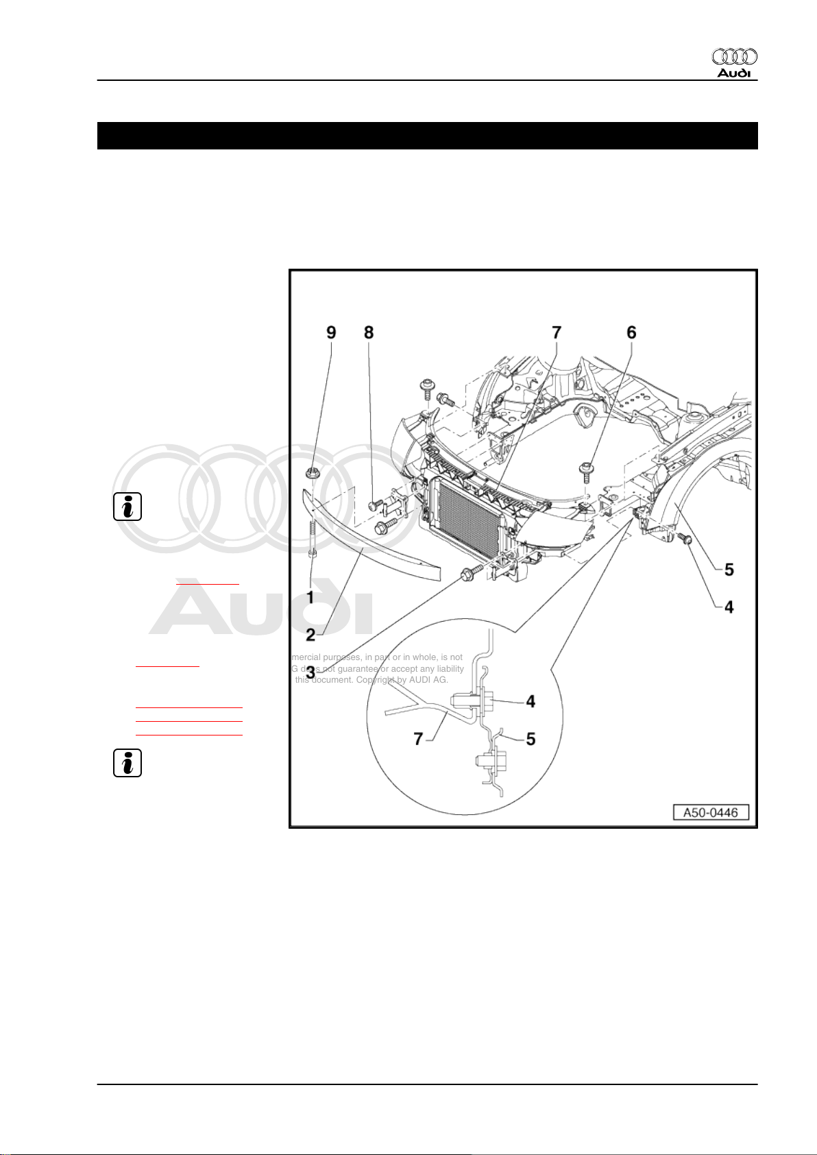
1.1 Removing and installing lock carrier with attachments
1 - Bolt with washer, 23 Nm
2 - Bumper
❑ Does not need to be de‐
tached from bumper
brackets when remov‐
ing the lock carrier.
3 - Hexagon bolt, 35 Nm
4 - Torx bolt T30, 6 Nm
5 - Wing panel
6 - Bolt with washer, 23 Nm
7 - Lock carrier
Audi TT 1999 ➤
Note
❑ Removing:
– Remove bumper cover
(front) ⇒ page 86 .
– Unplug electrical con‐
nectors for headlights.
– Remove bonnet lock
⇒ page 12 .
– Unscrew bolts
⇒ Item 3 (page 1) ,
⇒ Item 4 (page 1) and
⇒ Item 6 (page 1) .
Note
– Detach lock carrier to
front.
❑ Install in reverse sequence.
8 - Bolt, 4 Nm
9 - Hexagon nut, 23 Nm
1. Body - front 1
Page 8
Protected by copyright. Copying for private or commercial purposes, in part or in whole, is not
permitted unless authorised by AUDI AG. AUDI AG does not guarantee or accept any liability
with respect to the correctness of information in this document. Copyright by AUDI AG.
Audi TT 1999 ➤
General body repairs, exterior - Edition 07.2004
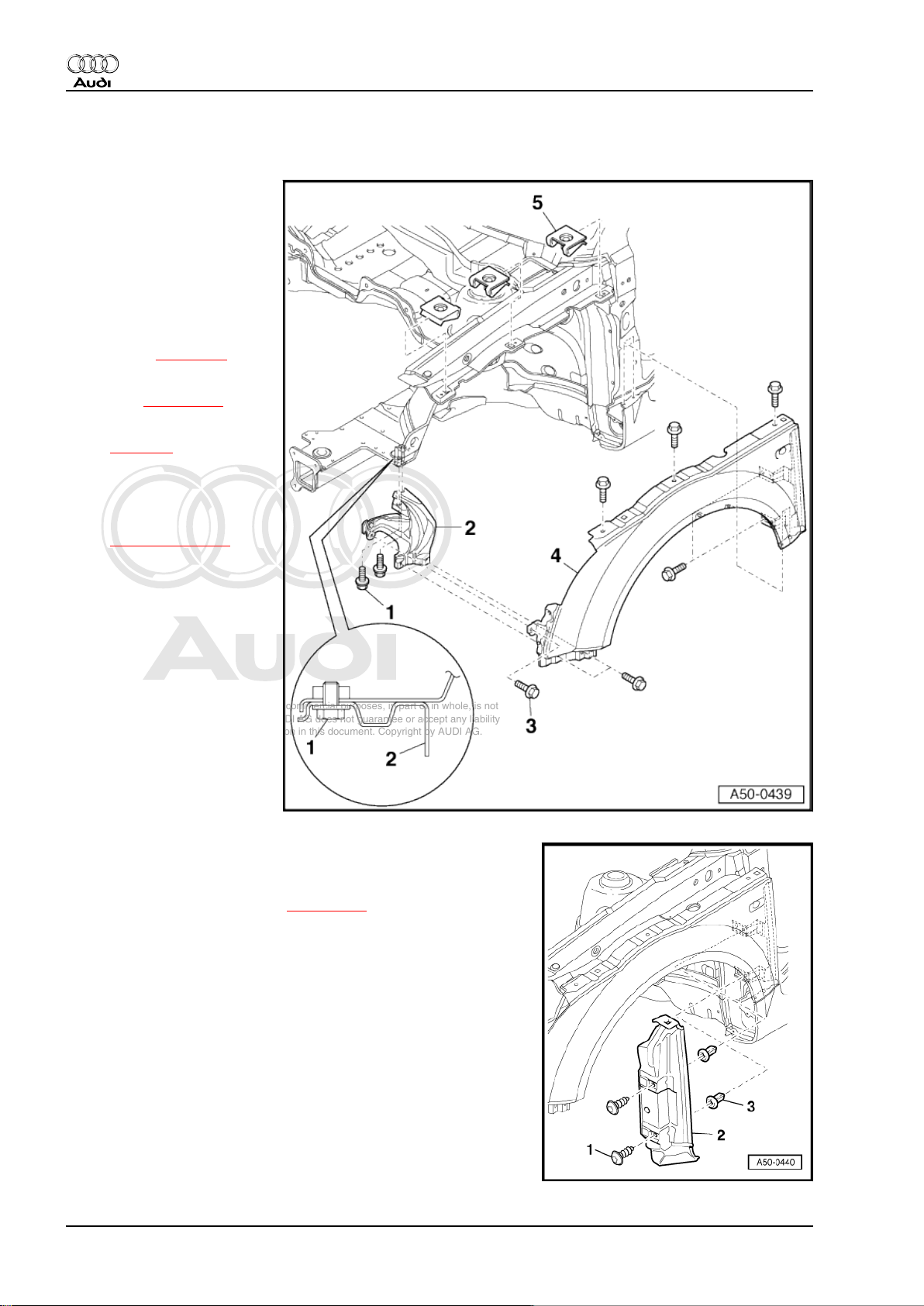
1.2 Wing panel (front) - overview
1 - Bolt with washer, 10 Nm
2 - Brace
3 - Bolt with washer, 15 Nm
❑ Qty. 8
4 - Wing panel
❑ Removing:
– Remove bumper cover
(front) ⇒ page 86 .
– Remove wheel housing
liner ⇒ page 129 .
– Remove end plate
⇒ page 2 .
– Detach headlight.
– Unscrew bolts with
washers
⇒ Item 3 (page 2) and
detach wing.
❑ Install in reverse se‐
quence.
5 - Speed nuts
❑ Are inserted into wing
mounting flange.
Removing and installing end plate
– Remove front wheel.
– Remove wheel housing liner ⇒ page 129 .
– Remove bolts -1- from expanding clips -3- and remove end
plate -2- from wing.
2 Rep. Gr.50 - Body - front
Page 9
Protected by copyright. Copying for private or commercial purposes, in part or in whole, is not
permitted unless authorised by AUDI AG. AUDI AG does not guarantee or accept any liability
with respect to the correctness of information in this document. Copyright by AUDI AG.
Audi TT 1999 ➤
General body repairs, exterior - Edition 07.2004
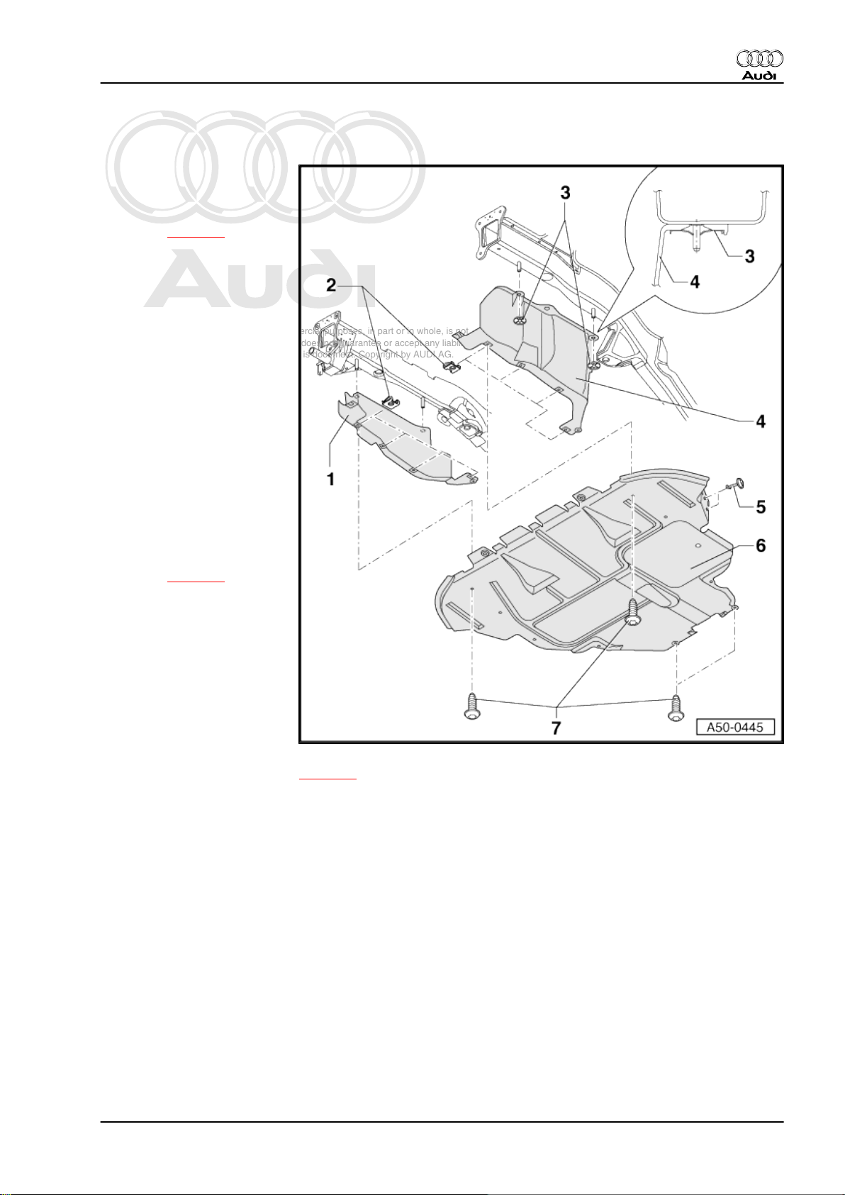
1.3 Noise insulation for vehicles with 4-cyl. engine - overview
1 - Noise insulation (left-side)
❑ Removing:
– Remove noise insula‐
tion ⇒ page 4 .
– Unscrew lock washers
and detach noise insu‐
lation (left-side).
❑ To install, insert retain‐
ing pegs (front) into lock
carrier (bottom).
2 - Speed nuts
❑ Qty. 7
3 - Lock washers
– To remove, unscrew
with a suitable screw‐
driver.
– To install just press on.
4 - Noise insulation (right-side)
❑ Removing:
– Remove noise insula‐
tion ⇒ page 4 .
– Unscrew lock washers
and detach noise insu‐
lation trim.
❑ To install, insert retain‐
ing pegs (front) into lock
carrier (bottom).
5 - Locking pin
❑ Qty. 4
6 - Noise insulation
❑ Removing and installing: ⇒ page 4 .
7 - Self-tapping screw, 2.2 Nm
1. Body - front 3
Page 10
Protected by copyright. Copying for private or commercial purposes, in part or in whole, is not
permitted unless authorised by AUDI AG. AUDI AG does not guarantee or accept any liability
with respect to the correctness of information in this document. Copyright by AUDI AG.
Audi TT 1999 ➤
General body repairs, exterior - Edition 07.2004
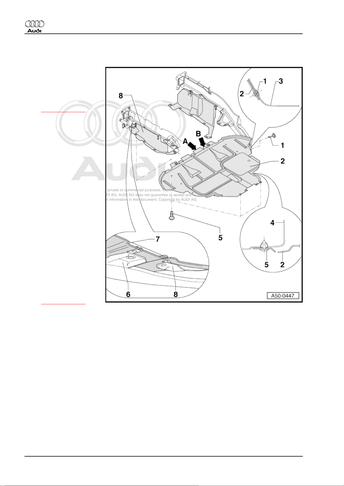
1.4 Removing and installing noise insulation for vehicles with 4-cyl. engine
1 - Locking pin
❑ Qty. 4
2 - Noise insulation
– To remove, unscrew
self-tapping screws
⇒ Item 5 (page 4)
and detach noise insu‐
lation from lock carrier
towards the rear.
– To install, insert tabs on
noise insulation (front)
above -arrow A- and be‐
low -arrow B- the lock
carrier.
3 - Wheel housing liner
4 - Subframe
5 - Self-tapping screw, 2.2 Nm
6 - Bumper cover
7 - Lock carrier with attach‐
ments
8 - Noise insulation (left-side)
❑ Removing:
– Remove noise insula‐
tion.
– Unscrew lock washers
and detach noise insu‐
lation (left-side).
❑ To install, insert retain‐
ing pegs (front) into lock
carrier (bottom)
⇒ Item 7 (page 4) .
4 Rep. Gr.50 - Body - front
Page 11
Protected by copyright. Copying for private or commercial purposes, in part or in whole, is not
permitted unless authorised by AUDI AG. AUDI AG does not guarantee or accept any liability
with respect to the correctness of information in this document. Copyright by AUDI AG.
Audi TT 1999 ➤
General body repairs, exterior - Edition 07.2004
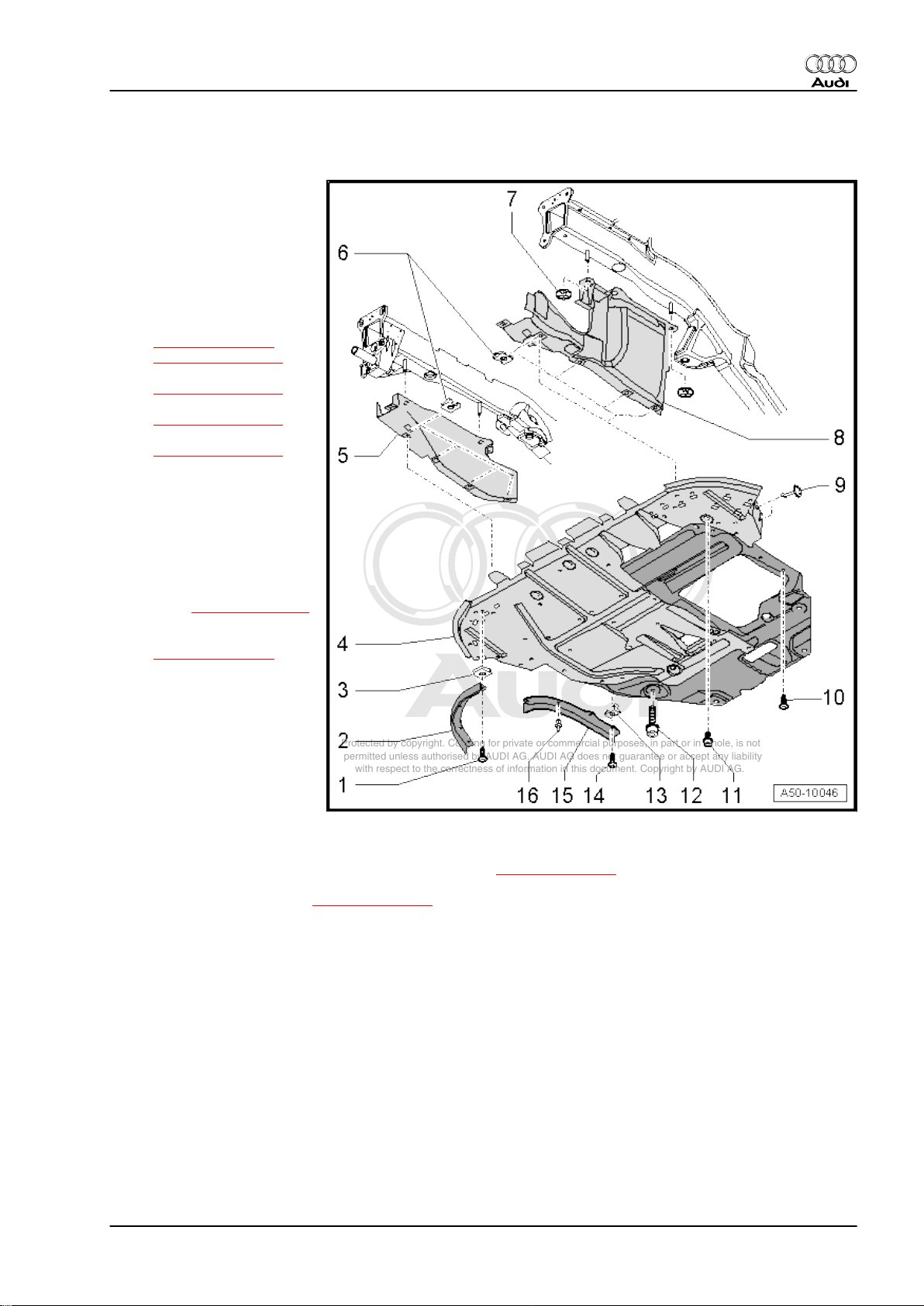
1.5 Removing and installing noise insulation for vehicles with 6-cyl. engine
1 - Self-tapping screw, 2.2 Nm
2 - Edge trim
3 - Speed nut
4 - Noise insulation with rein‐
forcement plate
– To remove, unscrew
self-tapping screws
⇒ Item 1 (page 5) ,
⇒ Item 10 (page 5)
and
⇒ Item 14 (page 5)
and socket head bolts
⇒ Item 11 (page 5)
and
⇒ Item 12 (page 5) .
Pull noise insulation out
of lock carrier towards
rear.
5 - Noise insulation (right-side)
❑ Removing:
– Remove noise insula‐
tion with reinforcement
plate ⇒ Item 4 (page 5) .
– Unscrew lock washers
⇒ Item 7 (page 5)
and detach noise insu‐
lation (right-side).
❑ To install, insert retain‐
ing pegs (front) into lock
carrier (bottom).
6 - Speed nut
7 - Lock washers
8 - Noise insulation (left-side)
❑ Removing:
– Remove noise insulation with reinforcement plate ⇒ Item 4 (page 5) .
– Unscrew lock washers ⇒ Item 7 (page 5) and detach noise insulation (left-side).
❑ To install, insert retaining pegs (front) into lock carrier (bottom).
9 - Locking pin
❑ Qty. 4
10 - Self-tapping screw, 2.2 Nm
11 - Socket head bolt M8x18, 25 Nm
❑ Qty. 8
12 - Socket head bolt M12x1.5x30, 120 Nm
❑ Qty. 2
13 - Spring clip
1. Body - front 5
Page 12
Protected by copyright. Copying for private or commercial purposes, in part or in whole, is not
permitted unless authorised by AUDI AG. AUDI AG does not guarantee or accept any liability
with respect to the correctness of information in this document. Copyright by AUDI AG.
Audi TT 1999 ➤
General body repairs, exterior - Edition 07.2004
14 - Self-tapping screw, 2.2 Nm
15 - Wheel spoiler (inner)
16 - Spreader rivet
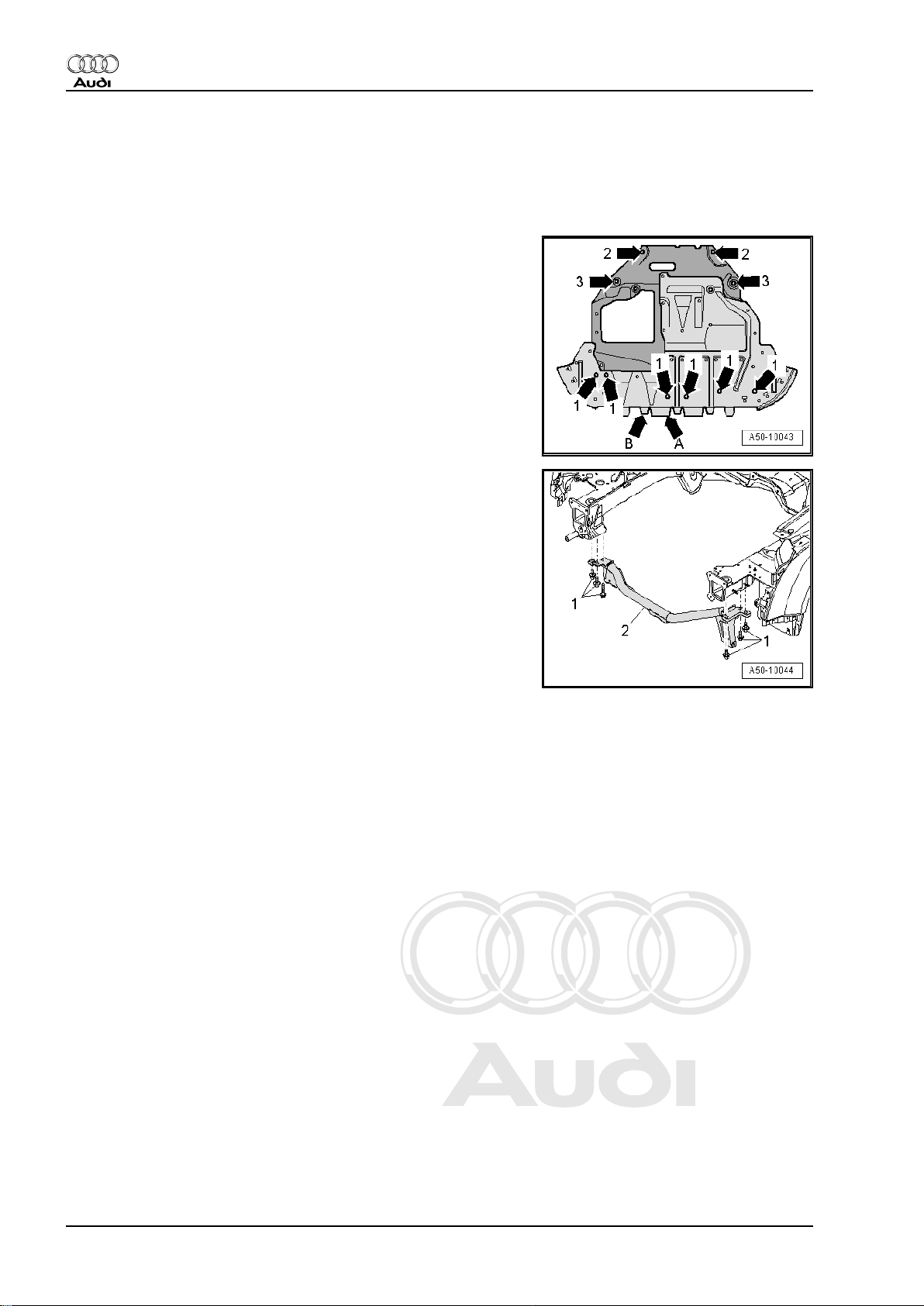
Installing noise insulation
– Insert tabs on noise insulation (front) above -arrow A- and be‐
low -arrow B- the lock carrier.
– Loosely screw in 6 socket head bolts M8 -arrows 1- and hand-
tighten 2 socket head bolts M8 -arrows 2-.
– Loosely screw in 2 socket head bolts M12 -arrows 3-, then
centralise noise insulation.
– Tighten all socket head bolts.
– Tighten all self-tapping screws.
Removing and installing tubular cross member
– When installing, tighten bolts -1- for tubular cross member
-2- to 20 Nm.
6 Rep. Gr.50 - Body - front
Page 13
Protected by copyright. Copying for private or commercial purposes, in part or in whole, is not
permitted unless authorised by AUDI AG. AUDI AG does not guarantee or accept any liability
with respect to the correctness of information in this document. Copyright by AUDI AG.
Audi TT 1999 ➤
General body repairs, exterior - Edition 07.2004
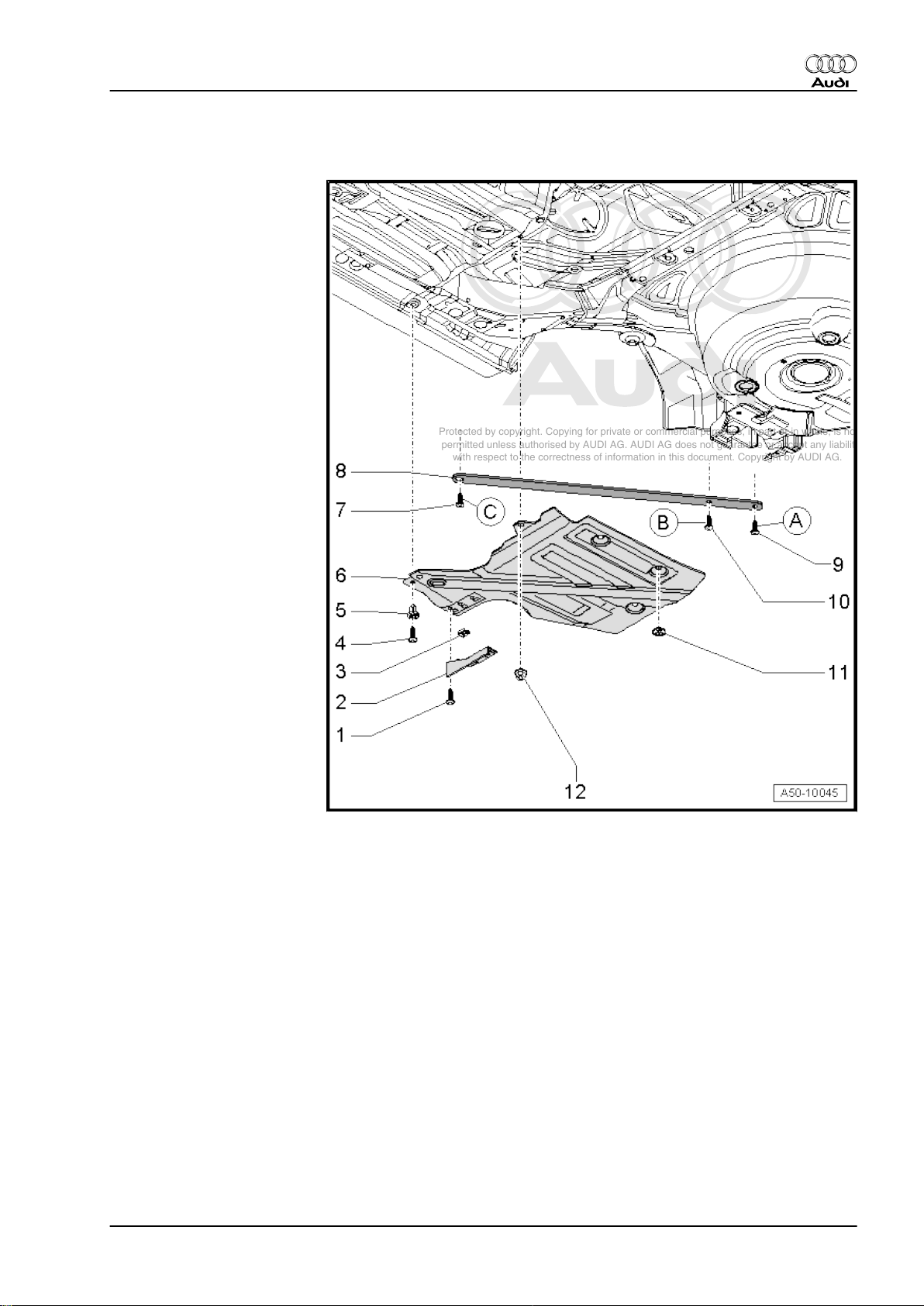
1.6 Body reinforcements (rear) for vehicles with 6-cyl. engine
1 - Self-tapping screw, 1.5 Nm
❑ Qty. 6
2 - Wheel spoiler (rear)
3 - Speed nut
❑ Qty. 6
4 - Self-tapping screw, 1.5 Nm
❑ Qty. 4
5 - Expanding nut
❑ Qty. 4
6 - Floor trim for fuel tank
7 - Pan-head bolt, 65 Nm
❑ Qty. 5
❑ Tighten in sequence:
“A”, “B”, “C”.
8 - Diagonal strut
9 - Pan-head bolt, 65 Nm
❑ Qty. 5
❑ Tighten in sequence:
“A”, “B”, “C”.
10 - Pan-head bolt, 65 Nm
❑ Qty. 5
❑ Tighten in sequence:
“A”, “B”, “C”.
11 - Lock washers
❑ Qty. 6
– To remove, unscrew
with a suitable screw‐
driver.
– To install just press on.
12 - Hexagon flange nut, 2.5 Nm
1. Body - front 7
Page 14

Protected by copyright. Copying for private or commercial purposes, in part or in whole, is not
permitted unless authorised by AUDI AG. AUDI AG does not guarantee or accept any liability
with respect to the correctness of information in this document. Copyright by AUDI AG.
Audi TT 1999 ➤
General body repairs, exterior - Edition 07.2004
55 – Bonnet, rear lid
1 Bonnet
1.1 Contact corrosion
Contact corrosion can occur if unsuitable fasteners are used on
the vehicle (bolts, nuts, washers etc.).
For this reason, only fasteners with a special surface coating
(Dachromet) have been fitted on the vehicle. These fasteners can
be identified by their greenish colour.
In addition, all rubber and plastic parts and all adhesives are made
of non-conductive materials.
Always renew parts if you are in any doubt as to whether the old
part can be used again.
Please note the following:
♦ Always use genuine replacement parts (same as original
equipment). These have been tested and are aluminium-com‐
patible.
♦ Accessories must be approved by AUDI AG.
♦ Damage resulting from contact corrosion is not covered by the
warranty.
8 Rep. Gr.55 - Bonnet, rear lid
Page 15
Protected by copyright. Copying for private or commercial purposes, in part or in whole, is not
permitted unless authorised by AUDI AG. AUDI AG does not guarantee or accept any liability
with respect to the correctness of information in this document. Copyright by AUDI AG.
General body repairs, exterior - Edition 07.2004
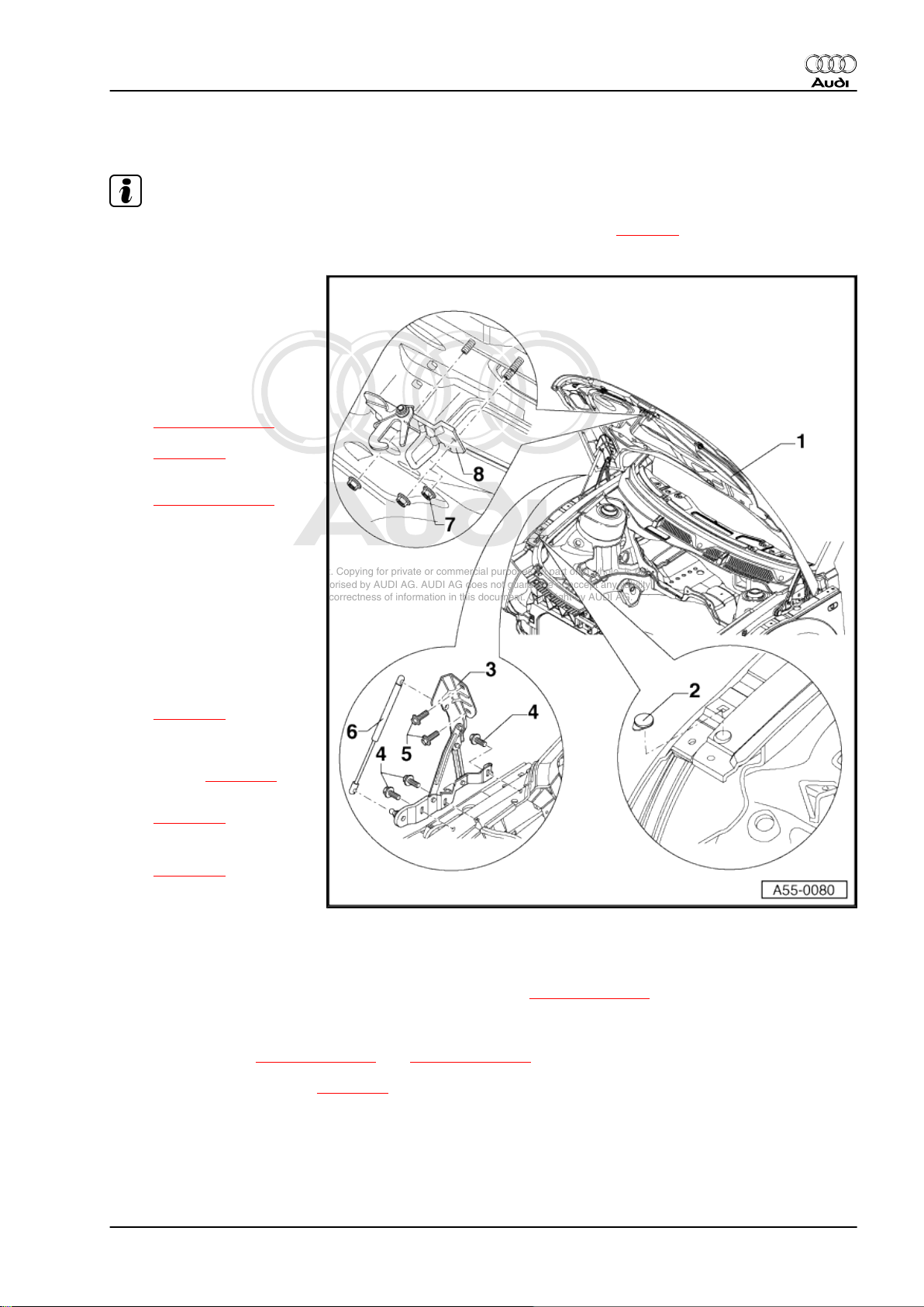
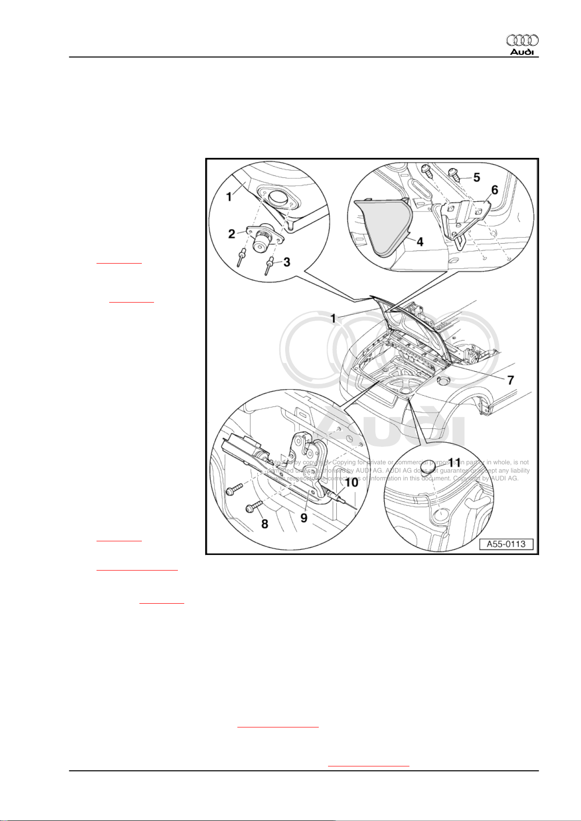
1.2 Removing and installing bonnet, adjusting bonnet
Note
The bonnet is made of aluminium. Please observe the notes on corrosion ⇒ page 8 .
1 - Bonnet
• When removing or instal‐
ling the bonnet, a 2nd me‐
chanic is required to sup‐
port and hold the bonnet.
❑ Removing:
– Detach gas-filled strut
⇒ Item 6 (page 9)
from bonnet
⇒ page 11 .
– Unscrew hexagon bolts
⇒ Item 5 (page 9) .
Audi TT 1999 ➤
– Detach bonnet.
❑ Install in reverse se‐
quence.
❑ Adjusting:
– Centralise bonnet be‐
tween the wings.
– Adjust height of bonnet
via bottom section of
bonnet lock
⇒ page 12 .
– Adjust position of bon‐
net to wings via the stop
buffers ⇒ page 10 .
❑ Panel gaps
⇒ page 10
❑ Removing and installing
bonnet lining
⇒ page 11 .
2 - Protective film
❑ Self-adhesive
❑ Peel off protective film before mounting.
3 - Bonnet hinge
• When installing or removing the bonnet hinge, the bonnet ⇒ Item 1 (page 9) must be removed or properly
secured.
❑ Removing:
– Unscrew bolts ⇒ Item 4 (page 9) and ⇒ Item 5 (page 9) .
– Remove gas-filled strut ⇒ page 11 .
❑ Install in reverse sequence.
4 - Hexagon bolt, 21 Nm
5 - Hexagon bolt, 21 Nm
1. Bonnet 9
Page 16
Protected by copyright. Copying for private or commercial purposes, in part or in whole, is not
permitted unless authorised by AUDI AG. AUDI AG does not guarantee or accept any liability
with respect to the correctness of information in this document. Copyright by AUDI AG.
Audi TT 1999 ➤
General body repairs, exterior - Edition 07.2004
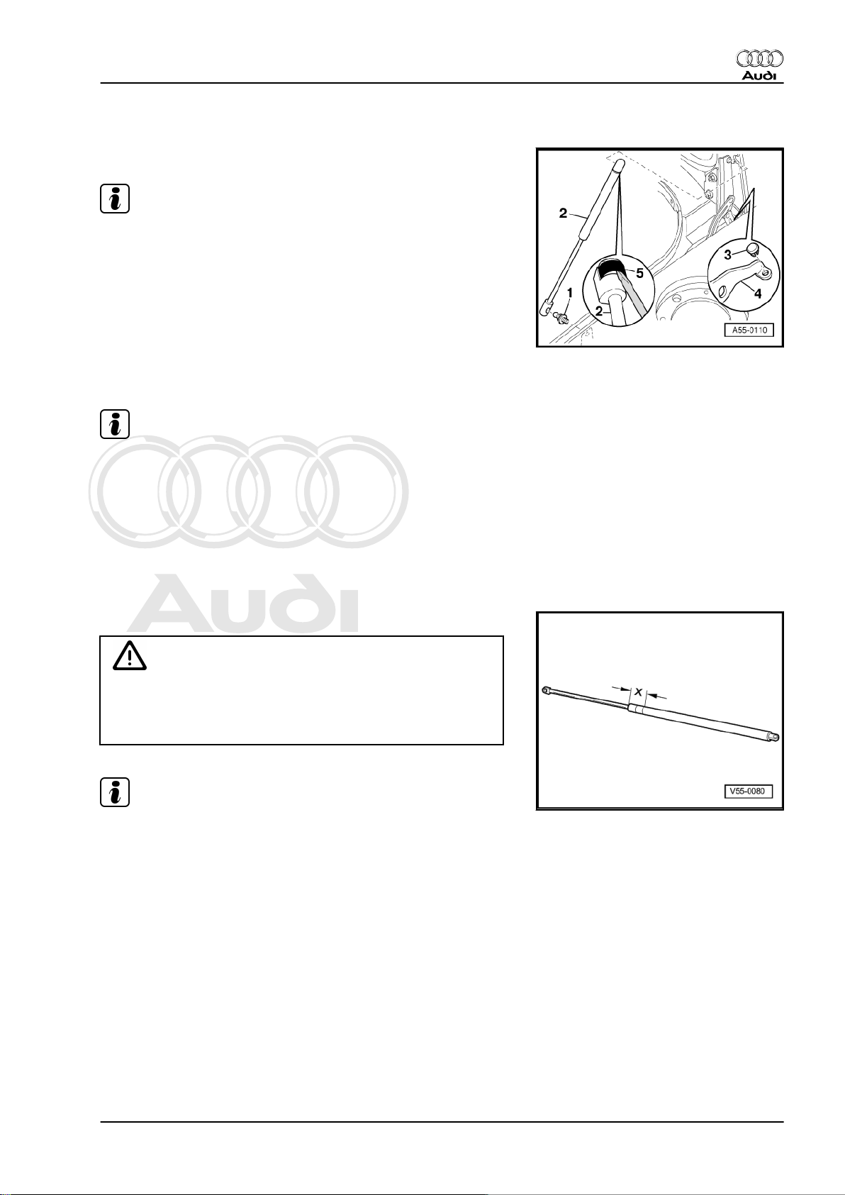
6 - Gas-filled strut
❑ Removing and installing: ⇒ page 11 .
❑ The cylinder end of the gas-filled strut must be installed on the bonnet side.
7 - Hexagon nut, 8 Nm
8 - Arrester
❑ Removing:
– Open bonnet.
– Unscrew hexagon nuts ⇒ Item 7 (page 10) and remove arrester.
❑ Install in reverse sequence.
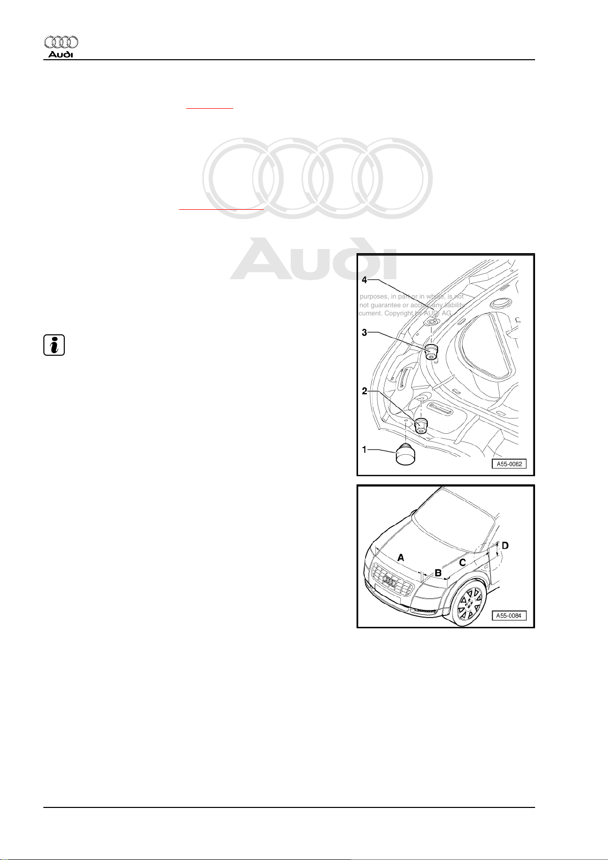
Adjusting height of stop buffers
• When bonnet -4- is closed, stop buffers -2- and -3- must rest
lightly on lock carrier.
• Rubber buffer -1- is used as impact protection and should not
make contact when bonnet is closed.
Note
The stop buffers can be used for adjusting the height of the bon‐
net.
Panel gaps
The panel gaps can be checked using setting gauge -3371- .
•
In section -A- = 4.0 mm
•
In section -B- = 4.0 mm
•
In section -C- = 4.0 mm
•
In section -D- = 4.0 mm
+ 1 mm
+ 1 mm
+ 1 mm
+ 1 mm
10 Rep. Gr.55 - Bonnet, rear lid
Page 17
Protected by copyright. Copying for private or commercial purposes, in part or in whole, is not
permitted unless authorised by AUDI AG. AUDI AG does not guarantee or accept any liability
with respect to the correctness of information in this document. Copyright by AUDI AG.
General body repairs, exterior - Edition 07.2004
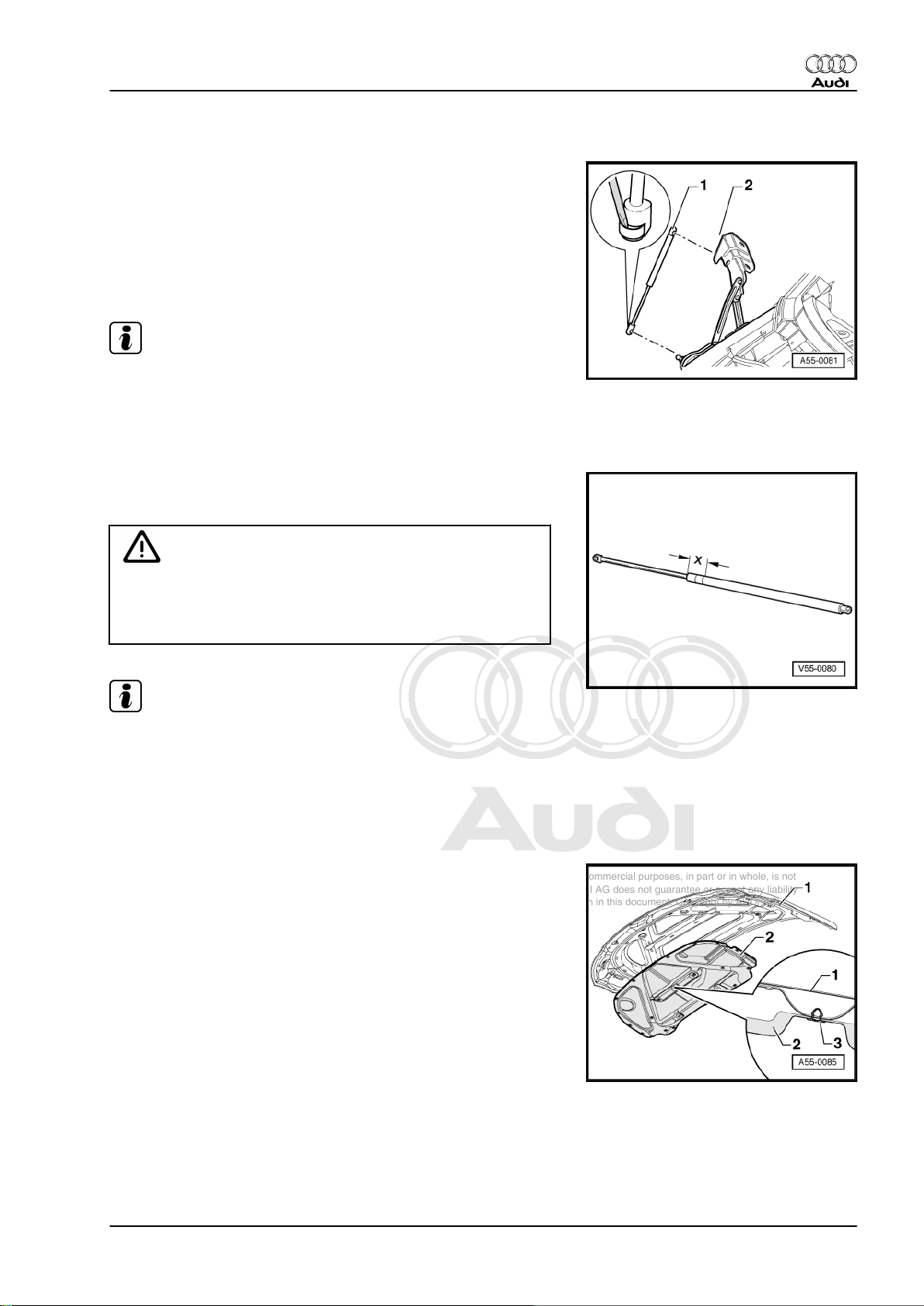
1.3 Removing and installing gas-filled strut
Removing
– Prop up and secure bonnet in open position.
– Use a small screwdriver to lift retaining clip slightly and pull
gas-filled strut -1- off ball stud (top) -2-.
– Perform same steps at ball stud (bottom).
Installing
Note
If gas-filled strut has been completely removed make sure it is reinstalled in the correct position. The cylinder end of the gas-filled
strut must be engaged on the bonnet side.
– Press gas-filled strut onto ball stud and make sure it engages.
Releasing gas from gas-filled strut
– Clamp section -x = 50 mm- of gas-filled strut in a vice.
Audi TT 1999 ➤
WARNING
♦ Only the section indicated may be clamped in the vice
(accident risk!).
♦ Always wear safety goggles while sawing.
Note
Cover area around saw cut with a cloth to catch any fluid which
may escape.
– Saw open the first third of the cylinder part of the gas-filled strut
(measured from the strut rod end of the cylinder).
1.4 Removing and installing bonnet lining
Removing
– Disengage clips -3- (18x) at bonnet -1- and detach lining -2-.
Installing
Install in reverse order.
1. Bonnet 11
Page 18
Protected by copyright. Copying for private or commercial purposes, in part or in whole, is not
permitted unless authorised by AUDI AG. AUDI AG does not guarantee or accept any liability
with respect to the correctness of information in this document. Copyright by AUDI AG.
Audi TT 1999 ➤
General body repairs, exterior - Edition 07.2004
1.5 Removing and installing bottom section
of bonnet lock
Removing
– Disengage Bowden cable for bonnet ⇒ page 12 .
– Unscrew bolts -2- (Qty. 4). Tightening torque: 10 Nm.
– Take out bottom section of bonnet lock -1-.
Note
To adjust bonnet, move bottom section of bonnet lock up or down
as required.
Installing
Install in reverse order.
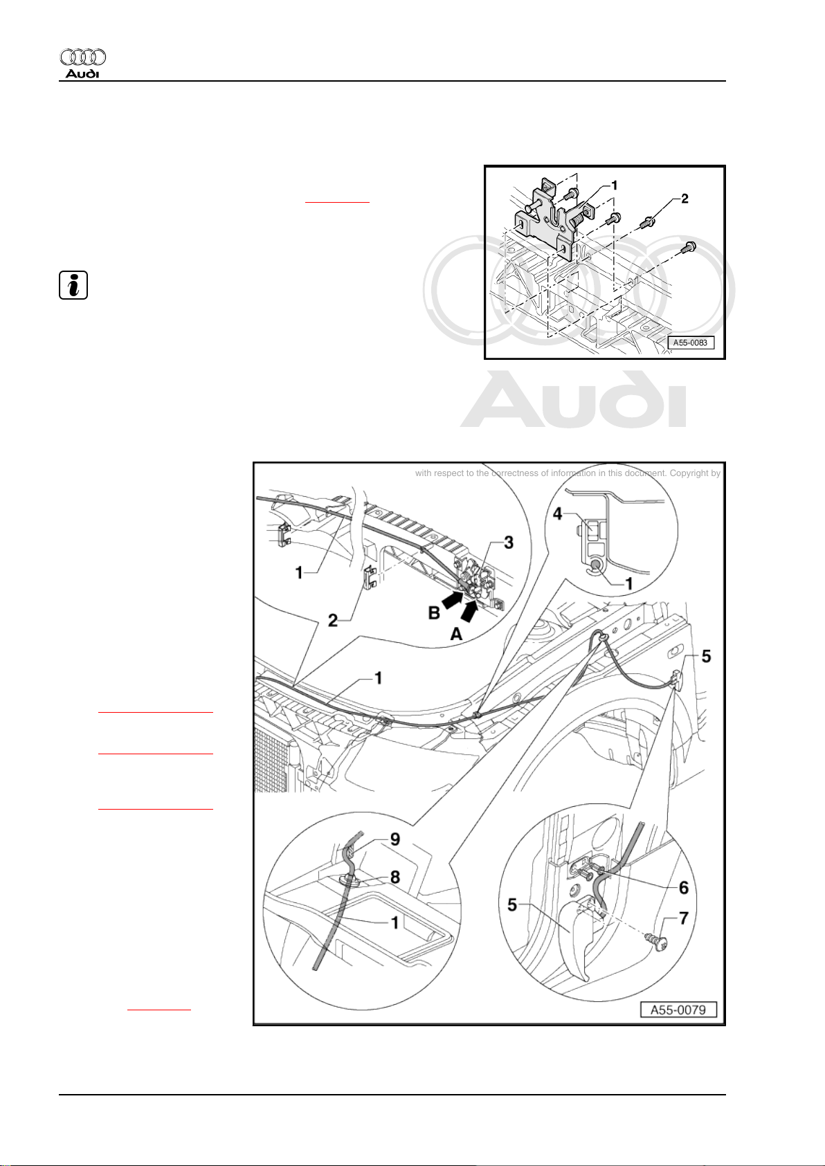
1.6 Removing and installing Bowden cable for bonnet lock
1 - Bowden cable for bonnet
lock
❑ Removing:
– Remove storage com‐
partment on driver's
side ⇒ General body re‐
pairs, interior; Rep. Gr.
68 .
– Unscrew bolts.
– Disengage Bowden ca‐
ble from support bracket
-arrow B- and eyelet
-arrow A- on bonnet lock
(bottom section)
⇒ Item 3 (page 12) .
– Detach retaining clip
⇒ Item 2 (page 12) .
– Disengage Bowden ca‐
ble from bracket
⇒ Item 4 (page 12) .
– Pull Bowden cable to‐
wards passenger com‐
partment of vehicle to
remove.
❑ Install in reverse se‐
quence.
2 - Retaining clip
3 - Bonnet lock (bottom sec‐
tion)
❑ Removing and instal‐
ling: ⇒ page 12 .
❑ Move up or down to ad‐
just bonnet.
12 Rep. Gr.55 - Bonnet, rear lid
Page 19

Protected by copyright. Copying for private or commercial purposes, in part or in whole, is not
permitted unless authorised by AUDI AG. AUDI AG does not guarantee or accept any liability
with respect to the correctness of information in this document. Copyright by AUDI AG.
4 - Bracket for Bowden cable
5 - Release lever for bonnet lock
6 - Expanding nut
7 - Fillister head self-tapping screw, 1.5 Nm
8 - Grommet
❑ When installing, make sure it is seated correctly.
9 - Edge protection
❑ Must be pushed onto edge of metal panel.
Audi TT 1999 ➤
General body repairs, exterior - Edition 07.2004
1. Bonnet 13
Page 20
Protected by copyright. Copying for private or commercial purposes, in part or in whole, is not
permitted unless authorised by AUDI AG. AUDI AG does not guarantee or accept any liability
with respect to the correctness of information in this document. Copyright by AUDI AG.
Audi TT 1999 ➤
General body repairs, exterior - Edition 07.2004
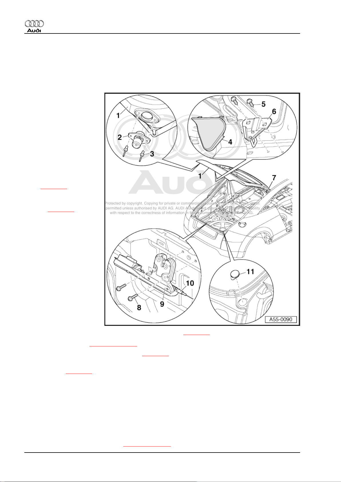
2 Rear lid - Coupé
2.1 Removing and installing rear lid, adjusting rear lid
1 - Rear lid
• When removing or instal‐
ling the rear lid, a 2nd me‐
chanic is required to sup‐
port and hold the rear lid.
❑ Removing:
– Remove rear lid lining.
– Detach electrical wiring
and pull completely out
of rear lid.
– Remove gas-filled struts
(left and right)
⇒ page 16 .
– Unscrew hexagon bolts
securing hinges to rear
lid ⇒ page 16 .
– Detach rear lid.
❑ Install in reverse se‐
quence.
❑ Adjusting:
• Gas-filled struts must be fit‐
ted before adjusting new
rear lid.
– Height and longitudinal
adjustments at top of
rear lid must be made
via rear lid hinge.
– Height adjustments at
bottom of rear lid must
be made via rear lid
lock.
– Align rear lid centrally according to specified panel gaps ⇒ page 15 .
– Adjust stop buffers ⇒ Item 2 (page 14) .
❑ Removing and installing seal for rear lid ⇒ page 17 .
2 - Stop buffers (2x)
❑ Adjusting ⇒ page 15 .
3 - Pop rivet
❑ To remove, drill out rivet heads and knock out rivet stems.
4 - Cover
❑ Unclip
5 - Bolt with washer, 12 Nm
6 - Striker plate
❑ Adjusting:
– Hand-tighten bolts with washers ⇒ Item 5 (page 14) (it must still be possible to move striker plate).
14 Rep. Gr.55 - Bonnet, rear lid
Page 21
Protected by copyright. Copying for private or commercial purposes, in part or in whole, is not
permitted unless authorised by AUDI AG. AUDI AG does not guarantee or accept any liability
with respect to the correctness of information in this document. Copyright by AUDI AG.
Audi TT 1999 ➤
General body repairs, exterior - Edition 07.2004
– Carefully close rear lid until it is flush with rear side panels.
– Carefully open rear lid and tighten bolts with washers ⇒ Item 5 (page 14) .
7 - Rear lid hinge
❑ Removing and installing: ⇒ page 16 .
8 - Bolt with washer, 8 Nm
9 - Rear lid lock
❑ To remove, unscrew bolts with washers ⇒ Item 8 (page 15) and disengage Bowden cable.
10 - Bowden cable for rear lid lock
❑ Removing and installing: ⇒ page 18 .
11 - Protective film
❑ Self-adhesive
❑ Peel off protective film before mounting.
Adjusting stop buffers
– Loosen clamping bolt -2- and pull stop buffer out slightly.
– Close rear lid -4- and align with body; at the same time, rear
lid lock must engage in 2nd stop of striker plate.
• This will push stop buffers -3- into correct position.
– Open rear lid and pull stop buffers out one stop.
– Tighten clamping bolt -2- to 2 Nm.
– Close rear lid.
– Check panel gaps ⇒ page 15 .
Note
To remove stop buffer drill rivet head off pop rivet -1-, knock out
rivet stem and detach buffer stop.
Panel gaps
The panel gaps can be checked using setting gauge -3371- .
•
In section -A- = 4.5 mm
•
In section -B- = 3.5 mm
•
In section -C- = 5.0 mm
+ 1 mm
+ 1 mm
+ 1 mm
2. Rear lid - Coupé 15
Page 22
Protected by copyright. Copying for private or commercial purposes, in part or in whole, is not
permitted unless authorised by AUDI AG. AUDI AG does not guarantee or accept any liability
with respect to the correctness of information in this document. Copyright by AUDI AG.
Audi TT 1999 ➤
General body repairs, exterior - Edition 07.2004
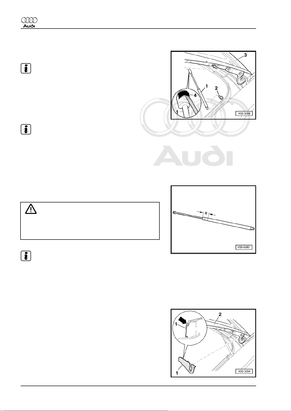
2.2 Removing and installing gas-filled strut
Removing
Note
When removing or installing gas-filled strut, push back open rear
lid -3- slightly, taking care not to damage any components.
– Use a screwdriver to slightly push back retaining springs -4-
at ends of gas-filled strut -1- and detach gas-filled strut from
ball studs -2-.
Installing
Note
If gas-filled strut has been completely removed make sure it is reinstalled in the correct position. The cylinder end of the gas-filled
strut must be engaged on the body side.
– Press gas-filled strut onto ball studs, first at bottom, then at
top.
•
Tightening torque for ball studs -2-: 15 Nm
Releasing gas from gas-filled strut
– Clamp section -x = 50 mm- of gas-filled strut in a vice.
WARNING
– 1 Nm
♦ Only the section indicated may be clamped in the vice
(accident risk!).
♦ Always wear safety goggles while sawing.
Note
Cover area around saw cut with a cloth to catch any fluid which
may escape.
– Saw open the first third of the cylinder part of the gas-filled strut
(measured from the strut rod end of the cylinder).
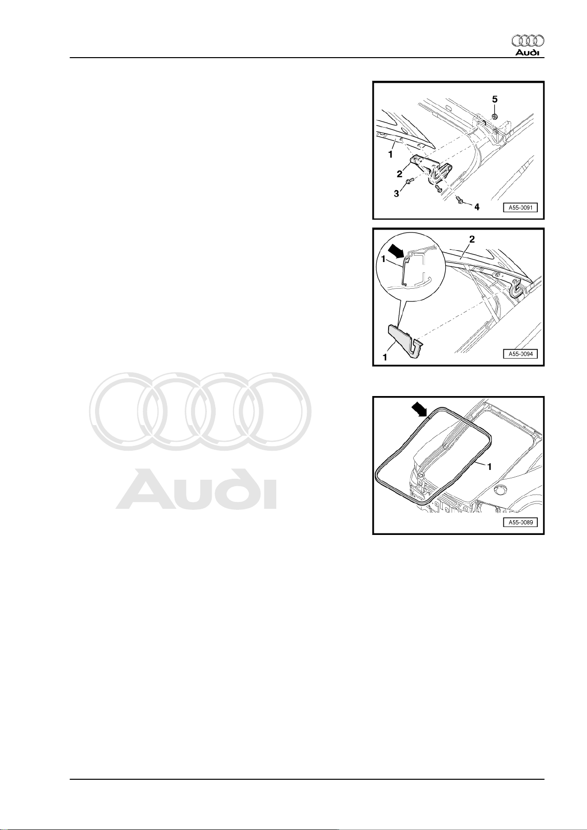
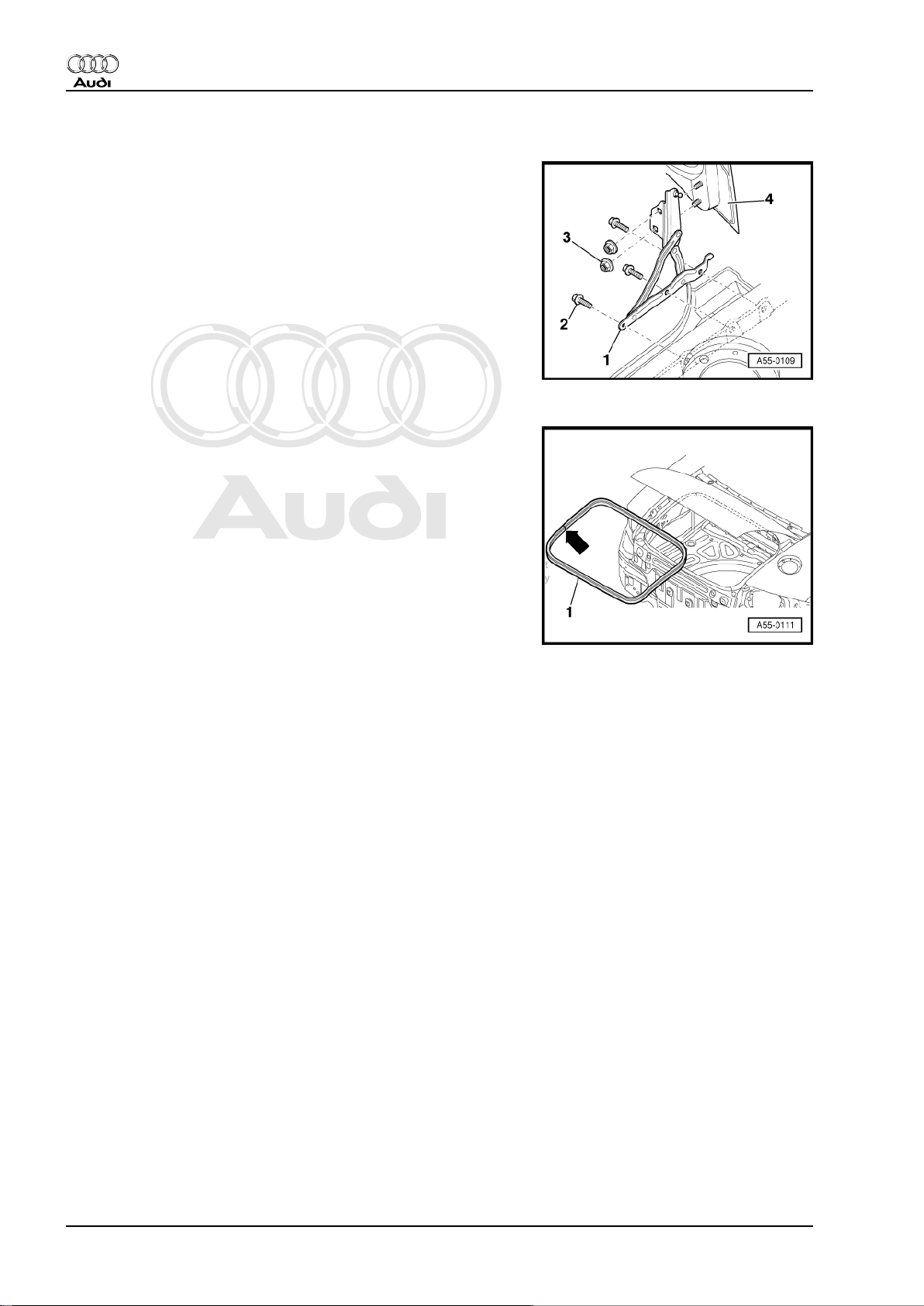
2.3 Removing and installing rear lid hinge
Removing
– First lever out cover -1- for rear lid hinge at bottom, then detach
from rear lid -2-.
– Remove roof frame trim ⇒ General body repairs, interior; Rep.
Gr. 70 .
16 Rep. Gr.55 - Bonnet, rear lid
Page 23
Protected by copyright. Copying for private or commercial purposes, in part or in whole, is not
permitted unless authorised by AUDI AG. AUDI AG does not guarantee or accept any liability
with respect to the correctness of information in this document. Copyright by AUDI AG.
General body repairs, exterior - Edition 07.2004
– Unscrew hexagon bolts -4- and remove rear lid -1-.
– Unscrew hexagon bolt -3- and hexagon nut -5-. Then detach
rear lid hinge -2-.
Installing
– Install and adjust rear lid hinge and rear lid.
– Tighten hexagon nut -5- and hexagon bolts -3- and -4- to
21 Nm.
– First engage cover with notches -arrow- at top in roof flange.
Audi TT 1999 ➤
2.4 Removing and installing seal for rear lid
Removing
– Open rear lid and pull off seal -1-.
Installing
• Butt joint -arrow- of seal for rear lid must be aligned with ball
socket of hinge (left-side).
– When installing seal, start in bottom corners (left and right).
– Press seal onto body as shown in illustration.
2. Rear lid - Coupé 17
Page 24
Protected by copyright. Copying for private or commercial purposes, in part or in whole, is not
permitted unless authorised by AUDI AG. AUDI AG does not guarantee or accept any liability
with respect to the correctness of information in this document. Copyright by AUDI AG.
Audi TT 1999 ➤
General body repairs, exterior - Edition 07.2004
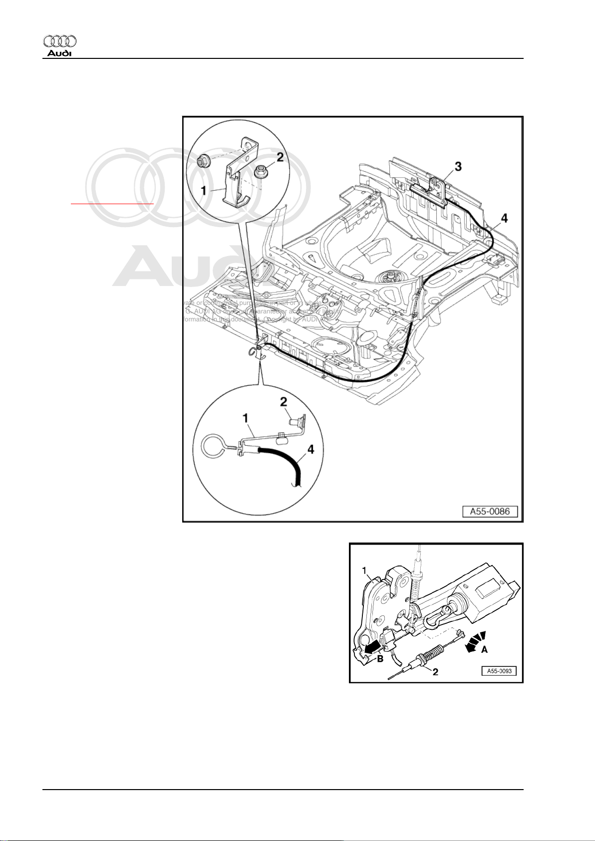
2.5 Removing and installing Bowden cable for rear lid lock
1 - Retaining bracket for Bow‐
den cable
2 - Hexagon nut, 5 Nm
3 - Rear lid lock
❑ Removing and instal‐
ling:
⇒ Item 9 (page 15) .
4 - Bowden cable for rear lid
lock
❑ Engage in retaining
bracket as illustrated.
Engaging and disengaging Bowden cable for rear lid lock
• Rear lid lock -1- removed.
– Lift Bowden cable -2- out of support bracket -arrow B-.
– Pivot Bowden cable 90° -arrow A- and take out of rear lid lock.
18 Rep. Gr.55 - Bonnet, rear lid
Page 25
Protected by copyright. Copying for private or commercial purposes, in part or in whole, is not
permitted unless authorised by AUDI AG. AUDI AG does not guarantee or accept any liability
with respect to the correctness of information in this document. Copyright by AUDI AG.
General body repairs, exterior - Edition 07.2004
3 Rear lid - Roadster
3.1 Removing and installing rear lid, adjusting rear lid
1 - Rear lid
• When removing or instal‐
ling the rear lid, a 2nd me‐
chanic is required to sup‐
port and hold the rear lid.
❑ Removing:
– Remove gas-filled struts
(left and right)
⇒ page 21 .
– Unscrew hexagon bolts
securing hinges to rear
lid ⇒ page 22 .
– Detach rear lid.
❑ Install in reverse se‐
quence.
❑ Adjusting:
• Gas-filled struts must be fit‐
ted before adjusting new
rear lid.
– Height and longitudinal
adjustments at top of
rear lid must be made
via rear lid hinge.
Audi TT 1999 ➤
– Height adjustments at
bottom of rear lid must
be made via rear lid
lock.
– Align rear lid centrally
according to specified
panel gaps
⇒ page 20 .
– Adjust stop buffers
⇒ Item 2 (page 19) .
2 - Stop buffers (2x)
❑ Adjusting ⇒ page 20 .
3 - Pop rivet
❑ To remove, drill out rivet heads and knock out rivet stems.
4 - Cover
❑ Unclip
5 - Bolt with washer, 12 Nm
6 - Striker plate
❑ Adjusting:
– Hand-tighten bolts with washers ⇒ Item 5 (page 19) (it must still be possible to move striker plate).
– Carefully close rear lid until it is flush with rear side panels.
– Carefully open rear lid and tighten bolts with washers ⇒ Item 5 (page 19) .
3. Rear lid - Roadster 19
Page 26
Protected by copyright. Copying for private or commercial purposes, in part or in whole, is not
permitted unless authorised by AUDI AG. AUDI AG does not guarantee or accept any liability
with respect to the correctness of information in this document. Copyright by AUDI AG.
Audi TT 1999 ➤
General body repairs, exterior - Edition 07.2004
7 - Rear lid hinge
❑ Removing and installing: ⇒ page 22 .
8 - Bolt with washer, 8 Nm
9 - Rear lid lock
❑ To remove, unscrew bolts with washers ⇒ Item 8 (page 20) and disengage Bowden cable.
10 - Bowden cable for rear lid lock
❑ Removing and installing: ⇒ page 23 .
11 - Protective film
❑ Self-adhesive
❑ Peel off protective film before mounting.
Adjusting stop buffers
– Loosen clamping bolt -2- and pull stop buffer out slightly.
– Close rear lid -4- and align with body; at the same time, rear
lid lock must engage in 2nd stop of striker plate.
• This will push stop buffers -3- into correct position.
– Open rear lid and pull stop buffers out one stop.
– Tighten clamping bolt -2- to 2 Nm.
– Close rear lid.
– Check panel gaps ⇒ page 20 .
Note
To remove stop buffer drill rivet head off pop rivet -1-, knock out
rivet stem and detach buffer stop.
Panel gaps
The panel gaps can be checked using setting gauge -3371- .
•
In section -A- = 3.5 mm
•
In section -B- = 3.5 mm
•
In section -C- = 5.0 mm
+ 1 mm
+ 1 mm
+ 1 mm
20 Rep. Gr.55 - Bonnet, rear lid
Page 27
Protected by copyright. Copying for private or commercial purposes, in part or in whole, is not
permitted unless authorised by AUDI AG. AUDI AG does not guarantee or accept any liability
with respect to the correctness of information in this document. Copyright by AUDI AG.
General body repairs, exterior - Edition 07.2004
3.2 Removing and installing gas-filled strut
Removing
Note
When removing or installing gas-filled strut, push back open rear
lid slightly, taking care not to damage any components.
– Use a screwdriver to slightly push back retaining springs -5-
at ends of gas-filled strut and detach gas-filled strut -2- from
ball studs.
3 - Stop for rear lid
4 - Rear lid hinge
Installing
Note
If gas-filled strut has been completely removed make sure it is reinstalled in the correct position. The cylinder end of the gas-filled
strut must be engaged on the bonnet side.
Audi TT 1999 ➤
– Press gas-filled strut onto ball studs, first at bottom, then at
top.
•
Tightening torque for ball head stud: 15 Nm
- 1 Nm
.
Releasing gas from gas-filled strut
– Clamp section -x = 50 mm- of gas-filled strut in a vice.
WARNING
♦ Only the section indicated may be clamped in the vice
(accident risk!).
♦ Always wear safety goggles while sawing.
Note
Cover area around saw cut with a cloth to catch any fluid which
may escape.
– Saw open the first third of the cylinder part of the gas-filled strut
(measured from the strut rod end of the cylinder).
3. Rear lid - Roadster 21
Page 28
Protected by copyright. Copying for private or commercial purposes, in part or in whole, is not
permitted unless authorised by AUDI AG. AUDI AG does not guarantee or accept any liability
with respect to the correctness of information in this document. Copyright by AUDI AG.
Audi TT 1999 ➤
General body repairs, exterior - Edition 07.2004
3.3 Removing and installing rear lid hinge
Removing
– Unscrew hexagon nuts -3- and remove rear lid -4-.
– Unscrew hexagon bolts -2- and remove rear lid hinge -1-.
Installing
– Install and adjust rear lid hinge and rear lid.
– Tighten hexagon nuts -3- and hexagon bolts -2- to 21 Nm.
3.4 Removing and installing seal for rear lid
Removing
– Open rear lid and pull off seal -1-.
Installing
• Butt joint -arrow- of seal must be aligned with ball socket of
hinge (left-side).
– When installing seal, start in bottom corners (left and right).
– Press seal onto body all around.
22 Rep. Gr.55 - Bonnet, rear lid
Page 29
Protected by copyright. Copying for private or commercial purposes, in part or in whole, is not
permitted unless authorised by AUDI AG. AUDI AG does not guarantee or accept any liability
with respect to the correctness of information in this document. Copyright by AUDI AG.
General body repairs, exterior - Edition 07.2004
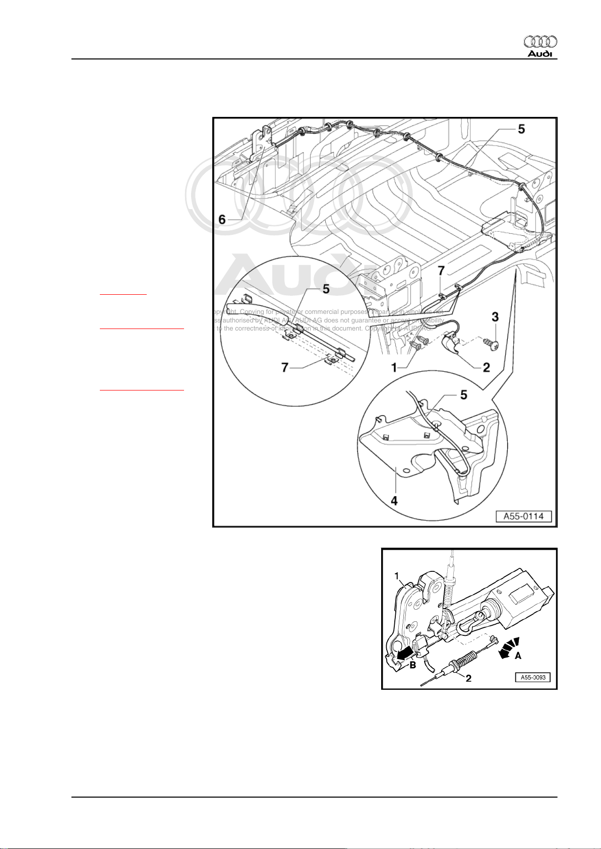
3.5 Removing and installing Bowden cable for rear lid lock
1 - Fastener
2 - Release lever for rear lid
lock
3 - Fillister head self-tapping
screw, 1.5 Nm
4 - Noise insulation (bottom
section)
❑ Can only be removed af‐
ter disassembling the
hydraulic pump.
5 - Bowden cable for rear lid
lock
❑ Disengaging
⇒ page 23
❑ Position in retaining
clips
⇒ Item 7 (page 23) as
illustrated.
6 - Rear lid lock
❑ Removing and instal‐
ling:
⇒ Item 9 (page 20) .
7 - Retaining clip for Bowden
cable
Audi TT 1999 ➤
Engaging and disengaging Bowden cable for rear lid lock
• Rear lid lock removed.
– Lift Bowden cable -2- out of support bracket -arrow B-.
– Pivot Bowden cable 90° -arrow A- and take out of rear lid lock.
3. Rear lid - Roadster 23
Page 30
Protected by copyright. Copying for private or commercial purposes, in part or in whole, is not
permitted unless authorised by AUDI AG. AUDI AG does not guarantee or accept any liability
with respect to the correctness of information in this document. Copyright by AUDI AG.
Audi TT 1999 ➤
General body repairs, exterior - Edition 07.2004
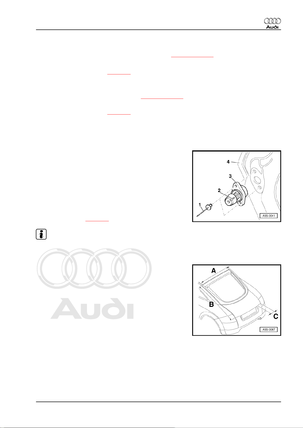
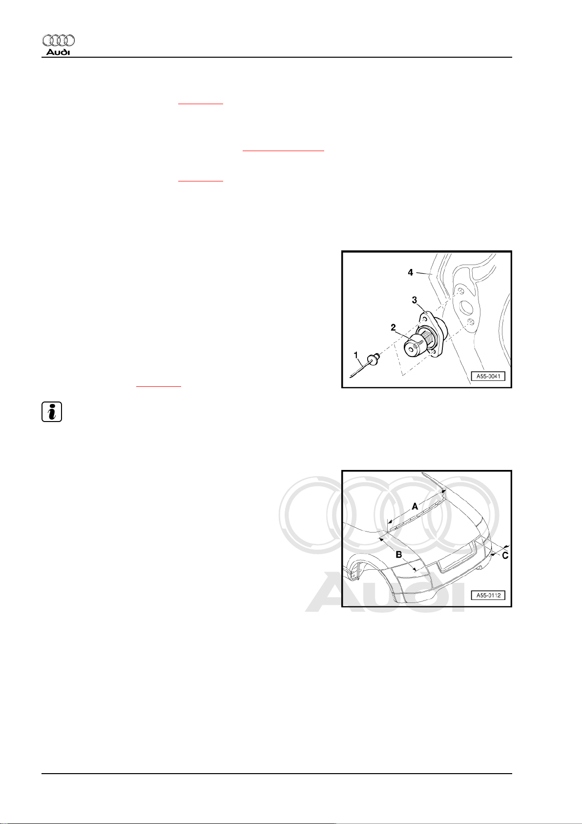
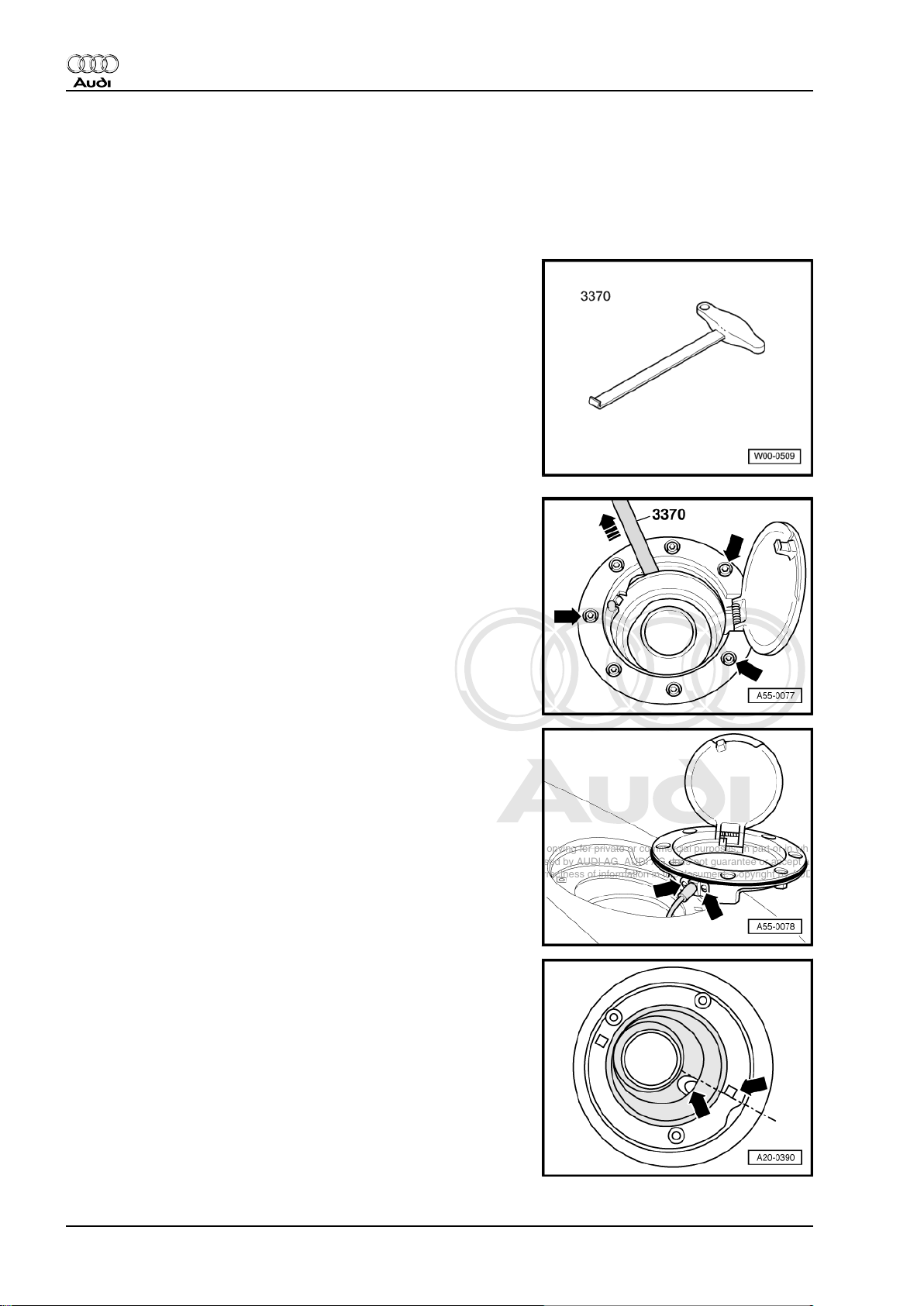
4 Tank flap
4.1 Removing and installing tank flap
Special tools and workshop equipment required
♦ Front-end hook -3370-
Removing
– Remove the three bolts -arrows-. Tightening torque: 4 Nm.
– Use front-end hook -3370- to pull fuel tank flap vertically up‐
wards out of body opening.
– Unscrew bolts -arrows- on release cable.
Installing
Installation is carried out in reverse order; note the following:
– To ensure overflow hose can be routed without kinking the
rubber cup must be installed as follows:
• The edge of drain hole must align with edge of square hole
-arrows- as shown in illustration.
24 Rep. Gr.55 - Bonnet, rear lid
Page 31

Protected by copyright. Copying for private or commercial purposes, in part or in whole, is not
permitted unless authorised by AUDI AG. AUDI AG does not guarantee or accept any liability
with respect to the correctness of information in this document. Copyright by AUDI AG.
Audi TT 1999 ➤
General body repairs, exterior - Edition 07.2004
57 – Front doors, door components, central locking
1 Front door
1.1 Removing and installing front door and door subframe
Special tools and workshop
equipment required
♦ Multi-point screwdriver -
T10011-
♦ Bit insert -3320/2-
♦ Socket -3410-
Overview
1. Front door 25
Page 32

Protected by copyright. Copying for private or commercial purposes, in part or in whole, is not
permitted unless authorised by AUDI AG. AUDI AG does not guarantee or accept any liability
with respect to the correctness of information in this document. Copyright by AUDI AG.
Audi TT 1999 ➤
General body repairs, exterior - Edition 07.2004
1 - Door subframe
Note
❑ Removing:
– Remove door trim ⇒
General body repairs,
interior; Rep. Gr. 70 .
– Unplug wires from door
subframe and unclip.
– Loosen hexagon nuts
⇒ Item 4 (page 26) .
– Unscrew hexagon bolts
⇒ Item 8 (page 27)
and hexagon nut
⇒ Item 9 (page 27) .
– Lift out door subframe.
❑ Installing:
• The front door
⇒ Item 5 (page 26) must
be adjusted ⇒ page 36
before installing door sub‐
frame.
– Insert door subframe in‐
to door, align with mark‐
ings applied before re‐
moving and secure
loosely.
– Adjust door subframe
⇒ page 30 .
2 - Motor for window lifter
❑ Removing:
Note
– Remove door trim ⇒ General body repairs, interior; Rep. Gr. 70 .
– Unscrew Torx bolts ⇒ Item 3 (page 26) and detach motor.
❑ Installing:
–
Tighten bolts to 3 Nm
+ 0.5 Nm
.
– When installing a new motor you have to adapt the force-resistance characteristic ⇒ page 27 .
Note
3 - Torx bolt, 3 Nm
4 - Hexagon nut, 30 Nm
5 - Front door
6 - Pop rivet
7 - Support
❑ To remove, drill out rivet heads and drive out rivet stems.
26 Rep. Gr.57 - Front doors, door components, central locking
Page 33

Protected by copyright. Copying for private or commercial purposes, in part or in whole, is not
permitted unless authorised by AUDI AG. AUDI AG does not guarantee or accept any liability
with respect to the correctness of information in this document. Copyright by AUDI AG.
Audi TT 1999 ➤
General body repairs, exterior - Edition 07.2004
❑ After the door subframe has been installed and adjusted, push up adjusting wedge so that support makes
contact between door and guide rail ⇒ page 27 .
8 - Hexagon bolts, 25 Nm
9 - Hexagon nut, 30 Nm
Adjusting the support
• Door subframe adjusted.
– Push adjusting wedge -3- of support -2- upwards to the limit
stop.
• When correctly adjusted, adjusting wedge must make contact
between door -1- and guide rail -4-.
1.2 Adapting and erasing force-resistance
characteristic for window lifter motor
Note
♦
The steps listed below have to be carried out after installing a
replacement part.
♦
Perform the steps described quickly, without any delays.
♦
If work is interrupted for longer than 10 seconds the adaption
mode is cancelled.
Requirements
• All trims and seals must be properly installed.
• Door and window lifter must be adjusted.
• Door must be fully assembled.
Adapting the force-resistance characteristic
– Close door and switch on ignition.
– Raise door window up to limit stop.
– Release window lifter switch.
– Pull window lifter switch up once again and hold in this position
for longer than 1 second.
– Now press window lifter switch to lower door window down to
limit stop in one movement.
– Raise door window up to limit stop in one movement.
– Release window lifter switch.
1. Front door 27
Page 34

Protected by copyright. Copying for private or commercial purposes, in part or in whole, is not
permitted unless authorised by AUDI AG. AUDI AG does not guarantee or accept any liability
with respect to the correctness of information in this document. Copyright by AUDI AG.
Audi TT 1999 ➤
General body repairs, exterior - Edition 07.2004
– Pull window lifter switch up once again and hold in this position
for longer than 1 second.
– This completes the adaption of the characteristic curve for the
window lifter.
– Activate the automatic open/close function.
Erasing the force-resistance characteristic
Note
♦
This procedure is necessary if the force-resistance character‐
istic curve proves to be too sensitive (e.g. after renewing the
seal).
♦
This means the door window reverses (moves back) without
any reason when closing.
Important: The procedure described in the following must be per‐
formed 3 times in a row within one minute.
• Door is closed and ignition is switched on.
– Open the door window and hold a wooden block or similar
object (approx. 8 ... 10 cm high) between door window and
upper limit stop.
– Close the door window with switch pulled upwards.
• The door window stops at the trapped object, the roll-back
function is activated and the door window moves downwards
slightly.
– Close the door window a second time with switch pulled up‐
wards.
• The door window stops at the trapped object again, the rollback function is activated once more and the door window
moves downwards slightly.
– Close the door window a third time with switch pulled upwards.
• Now the automatic reverse function is deactivated and the
window stops at the wooden block.
– Once the window lifter switch is released the door window will
move downwards after approx. 0.5 seconds.
– Close the door window a fourth time with switch pulled up‐
wards.
• The window will stop at the wooden block and not move down‐
wards after releasing the window lifter switch.
– Open the door window by pressing the window lifter switch.
– Release window lifter switch.
– Press the window lifter switch downwards for at least 1 sec‐
ond.
– Close the door window completely (now without wooden
block).
– Release window lifter switch.
– Now pull the window lifter switch upwards for at least 1 second.
Important: The steps described above must be repeated twice.
– Then you must adapt the force-resistance characteristic curve
again ⇒ page 27 .
28 Rep. Gr.57 - Front doors, door components, central locking
Page 35

Protected by copyright. Copying for private or commercial purposes, in part or in whole, is not
permitted unless authorised by AUDI AG. AUDI AG does not guarantee or accept any liability
with respect to the correctness of information in this document. Copyright by AUDI AG.
Audi TT 1999 ➤
General body repairs, exterior - Edition 07.2004
1.3 Adjusting door subframe - overview
Note
The door subframe can be adjusted in height, angle and longitudinal direction without having to remove the
door trim.
1 - Door with door subframe.
2 - Cover
❑ Lever out before making
longitudinal and height
adjustments.
3 - Lock nut (front), 30 Nm
4 - Adjuster screw (front), Torx
T 30
❑ For longitudinal adjust‐
ment
❑ Range of adjustment
-A- ± 5 mm from centre
position.
❑ When tightening lock
nut to torque setting, se‐
cure adjuster screw to
ensure it does not move.
5 - Door subframe
❑ Adjusting ⇒ page 30 .
6 - Adjuster screw (rear), Torx
T 30
❑ For longitudinal adjust‐
ment
❑ Range of adjustment
± 5 mm from centre po‐
sition.
❑ When tightening lock
nut to torque setting, se‐
cure adjuster screw to
ensure it does not move.
7 - Lock nut (rear), 30 Nm
8 - Trim cap
❑ Lever off before making
angle and height adjustments.
9 - Trim cap
❑ Lever off before making height adjustments.
10 - Trim cap
❑ Lever off before making longitudinal adjustments.
11 - Adjuster screw
❑ For adjusting the angle.
12 - Lock nut, 30 Nm
❑ Before tightening the nut to torque you must move stop bolt ⇒ Item 13 (page 29) back to limit stop.
13 - Stop bolt
❑ Must be moved back to limit stop after making height adjustments.
1. Front door 29
Page 36

Protected by copyright. Copying for private or commercial purposes, in part or in whole, is not
permitted unless authorised by AUDI AG. AUDI AG does not guarantee or accept any liability
with respect to the correctness of information in this document. Copyright by AUDI AG.
Audi TT 1999 ➤
General body repairs, exterior - Edition 07.2004
14 - Lock nut, 30 Nm
15 - Adjuster screw
❑ For height adjustment.
❑ Range of adjustment -B- ± 4 mm from centre position.
16 - Adjuster screw (bottom), Torx T 30
❑ Only loosen lock nut ⇒ Item 12 (page 29) to make angle and longitudinal adjustments.
❑ Must be screwed in before making height adjustments.
❑ After making adjustments unscrew adjuster screw again as far as the stop and tighten lock nut
⇒ Item 12 (page 29) to specified torque, securing adjuster screw to prevent it turning.
17 - Lock nut (bottom), 30 Nm
18 - Adjuster screw (bottom), Torx T 30
❑ For height adjustment.
❑ Range of adjustment ± 4 mm from centre position.
1.4 Adjusting door subframe
• The door ⇒ page 36 must be adjusted before adjusting door
subframe.
1 - Door with door subframe.
Longitudinal adjustment:
– Loosen lock nuts -3-,
-7- and -12-.
– Loosen hexagon bolts
⇒ Item 8 (page 27) (4x)
securing subframe to
door.
– When adjusting towards
rear first screw in the ad‐
juster screw -4-.
• One turn equals
approx. 1 mm adjustment
travel.
– Unscrew adjuster screw
-6- far enough for collar
of adjuster screw -4- to
make contact with front
of door.
– When adjusting the sub‐
frame towards the front,
perform reverse opera‐
tions.
Note
When tightening the lock nuts to
specified torque the adjuster screws
must be secured to prevent them
turning (Torx T30).
– Tighten lock nuts -3-,
-6- and -12- to specified
torque.
30 Rep. Gr.57 - Front doors, door components, central locking
Page 37

Protected by copyright. Copying for private or commercial purposes, in part or in whole, is not
permitted unless authorised by AUDI AG. AUDI AG does not guarantee or accept any liability
with respect to the correctness of information in this document. Copyright by AUDI AG.
Audi TT 1999 ➤
General body repairs, exterior - Edition 07.2004
– Tighten hexagon bolts ⇒ Item 8 (page 27) (securing subframe to door) to specified torque.
1 - Door with door subframe.
Height adjustment:
– Loosen lock nuts (top)
-3- and -7-.
– Loosen lock nuts (bot‐
tom) -12- and -14- at
rear and front.
Note
When adjusting to lower position
stop bolt -13- must also be screwed
in.
– Now you can adjust the
height via the adjuster
screws -15- (front and
rear).
– After performing adjust‐
ment unscrew stop bolt
-13- as far as limit stop.
Note
When tightening the lock nuts to
specified torque the adjuster screws
must be secured to prevent them
turning (Torx T30).
– Tighten lock nuts -3-
and -7- to specified tor‐
que.
– Tighten lock nuts (bot‐
tom) -12- and -14- at
front and rear to speci‐
fied torque.
1. Front door 31
Page 38

Protected by copyright. Copying for private or commercial purposes, in part or in whole, is not
permitted unless authorised by AUDI AG. AUDI AG does not guarantee or accept any liability
with respect to the correctness of information in this document. Copyright by AUDI AG.
Audi TT 1999 ➤
General body repairs, exterior - Edition 07.2004
1 - Door with door subframe.
Adjusting the angle:
– Lever out trim caps -8-,
-9- and -10-.
– Loosen lock nuts (bot‐
tom) -12- and -14- at
rear and front.
– Now you can adjust the
angle via the adjuster
screws -11- (front and/
or rear).
• Dimensions for adjustment
⇒ page 32 .
Note
When tightening the lock nuts to
specified torque the adjuster screws
must be secured to prevent them
turning (Torx T30).
– Tighten lock nuts (bot‐
tom) -12- and -14- at
front and rear to speci‐
fied torque.
Adjusting the angle at door subframe
Note
Make an improvised setting gauge to assist you in adjusting the
angle of the door window ⇒ page 33 .
– To ensure that there will be no leaks you must adjust door
subframe at distance -c- = 300 mm ±
10 mm
from guide rail
-1- in such a way that the following dimensions are attained:
•
TT Coupé: -a- = 6 mm
•
TT Roadster: -a- = 7 mm
± 1 mm
+ 1 mm
– The door subframe must also be adjusted in such a way that
the window fits into the seal so that distance -b- = 4 mm
+ 1 mm
.
32 Rep. Gr.57 - Front doors, door components, central locking
Page 39

Protected by copyright. Copying for private or commercial purposes, in part or in whole, is not
permitted unless authorised by AUDI AG. AUDI AG does not guarantee or accept any liability
with respect to the correctness of information in this document. Copyright by AUDI AG.
General body repairs, exterior - Edition 07.2004
Making improvised setting gauge
– Make improvised setting gauge from plastic or plywood ac‐
cording to the specified dimensions.
•
Dimension -a- = 2.5 mm
•
Dimension -b- on TT Coupé = 6 mm
•
Dimension -b- on TT Roadster = 7 mm
+ 2 mm
± 1 mm
+ 1 mm
– When door subframe is correctly adjusted, setting gauge -2-
must - when positioned at distance of approx. 300 mm from
guide rail - make contact with both door window and roof trim,
as shown.
Door hinge (top)
1 - Hexagon bolt, 30 Nm
2 - Door hinge (top)
3 - Torx bolt T45, 30 Nm
4 - Hexagon bolt, 30 Nm (fitted from inside of vehicle)
5 - Stud, 23 Nm
6 - Trim cap
Audi TT 1999 ➤
Door hinge (bottom)
1 - Door hinge (bottom)
2 - Hexagon bolt, 30 Nm
3 - Door
4 - Hexagon bolt, 30 Nm
5 - Torx bolt, 30 Nm
1. Front door 33
Page 40

Protected by copyright. Copying for private or commercial purposes, in part or in whole, is not
permitted unless authorised by AUDI AG. AUDI AG does not guarantee or accept any liability
with respect to the correctness of information in this document. Copyright by AUDI AG.
Audi TT 1999 ➤
General body repairs, exterior - Edition 07.2004
1.5 Removing and installing door window
1 - Side window
• Remove and install with
door subframe removed.
❑ Removing:
– Mark position of window
using a felt-tip pen.
– Unscrew Torx bolts
⇒ Item 2 (page 34)
and take out window.
❑ Install in reverse se‐
quence.
2 - Torx bolts, 8 Nm
3 - Door subframe
❑ Removing and instal‐
ling: ⇒ page 25 .
❑ Adjusting ⇒ page 30 .
4 - Door window
• Before removing, move
window upwards.
• Remove and install with
door subframe removed.
❑ Removing:
– Mark position of window
on both brackets with
felt-tip pen.
– Unscrew Torx bolts
⇒ Item 7 (page 34)
and detach window from
guide rail to the rear.
❑ Installing the "old" win‐
dow:
– Insert door window in guide rail ⇒ Item 11 (page 35) and position on window lifter, aligning it in centre
of actuators.
– Fit washers ⇒ Item 6 (page 34) and lock washers ⇒ Item 5 (page 34) and lightly tighten bolts
⇒ Item 7 (page 34) .
– Align door window with markings centrally to washers and lock washers and tighten bolts to 6 Nm.
❑ Installing a new door window:
– Position window on actuators at window lifter.
– Push window into guide rail ⇒ Item 11 (page 35) as far as it will go.
– Push the window parallel into the guide rail upwards until there is an even transition to the side window.
– Now pull window 0.5 ... 1 mm towards rear, out of guide rail.
– Fit washers ⇒ Item 6 (page 34) and lock washers ⇒ Item 5 (page 34) and tighten bolts
⇒ Item 7 (page 34) to 6 Nm.
5 - Lock washer (top)
6 - Washer (top)
34 Rep. Gr.57 - Front doors, door components, central locking
Page 41

Protected by copyright. Copying for private or commercial purposes, in part or in whole, is not
permitted unless authorised by AUDI AG. AUDI AG does not guarantee or accept any liability
with respect to the correctness of information in this document. Copyright by AUDI AG.
General body repairs, exterior - Edition 07.2004
7 - Torx bolt, 6 Nm
8 - Washer (bottom)
9 - Lock washer (bottom)
10 - Torx bolt, 8 Nm
❑ With this bolt the side window can be adjusted on side of A-pillar.
11 - Guide rail
• Removing and installing: ⇒ Item 3 (page 35) .
1.6 Removing and installing window lifter
1 - Bolt with washer, 8 Nm
2 - Seal
❑ Pull out to remove.
❑ For easier installation
moisten with soapy wa‐
ter and push into guide
rail.
3 - Guide rail
• Remove and install with
door subframe removed.
❑ To remove, unscrew
bolt with washer
⇒ Item 1 (page 35) and
drill off rivet heads of
pop rivets
⇒ Item 8 (page 35) .
4 - Window lifter
• Remove and install with
door subframe removed.
❑ To remove, drill off rivet
heads of pop rivets
⇒ Item 5 (page 35) ,
⇒ Item 6 (page 35)
and
⇒ Item 8 (page 35) ,
then detach window lift‐
er.
❑ Fitting Bowden cable
⇒ page 36
5 - Pop rivet
6 - Pop rivet
7 - Door subframe
❑ Removing and instal‐
ling: ⇒ page 25 .
Audi TT 1999 ➤
8 - Pop rivet
1. Front door 35
Page 42

Protected by copyright. Copying for private or commercial purposes, in part or in whole, is not
permitted unless authorised by AUDI AG. AUDI AG does not guarantee or accept any liability
with respect to the correctness of information in this document. Copyright by AUDI AG.
Audi TT 1999 ➤
General body repairs, exterior - Edition 07.2004
Fitting Bowden cable for window lifter
– Install window lifter -1- in such a way that cable guide -3- is
located on inside of door subframe -2-.
• The cable guide -4- must be located on the outer side of the
door subframe.
– Clip cable guide -3- into bracket -arrow-.
1.7 Adjusting door
Panel gaps
The panel gaps can be checked using setting gauge -3371- .
•
Dimension -A- = 4 mm
•
Dimension -B- = 4 mm
• Dimension -C- = 3.5 ... 4.5 mm
•
Dimension -D- = 5 mm
•
Dimension -E- = 3.5 mm
+ 1 mm
+ 1 mm
± 1.5 mm
+ 1 mm
Adjusting door at striker plate
– Slacken off bolts -2-.
– Move striker plate -1- until door shell is flush with body contour.
– Tighten bolts to 20 Nm.
Note
The striker plate must only be adjusted towards the centre of the
vehicle and not in height, as otherwise the lock could become
damaged.
36 Rep. Gr.57 - Front doors, door components, central locking
Page 43

Protected by copyright. Copying for private or commercial purposes, in part or in whole, is not
permitted unless authorised by AUDI AG. AUDI AG does not guarantee or accept any liability
with respect to the correctness of information in this document. Copyright by AUDI AG.
Audi TT 1999 ➤
General body repairs, exterior - Edition 07.2004
1.8 Door handle and door lock - exploded view
1 - Door lock
• Remove and install with
door trim removed ⇒ Gen‐
eral body repairs, interior;
Rep. Gr. 70 .
❑ Door lock can be re‐
moved without disman‐
tling the door subframe.
❑ Removing ⇒ page 38 .
2 - Bowden cable for releasing
the lock
3 - Mounting bracket
• Remove and install with
door handle and lock cylin‐
der housing removed.
❑ To remove, unscrew
cross-head screw
⇒ Item 4 (page 37) ,
push mounting bracket
slightly to rear and re‐
move from door.
4 - Cross-head screw, 4.5 Nm
5 - Door handle with backing
plate
❑ Removing and instal‐
6 - Trim cap
❑ Can be clipped on with
7 - Lock cylinder housing
❑ Removing ⇒ page 38 .
❑ Lock cylinder cannot be
8 - Backing plate
9 - Multi-point socket head bolt
❑ Use multi-point socket screwdriver -T10011- to loosen and tighten.
❑ Loosen this bolt to release lock cylinder housing ⇒ Item 7 (page 37) which can then be pulled out of
❑ Bolt must not be screwed in if lock cylinder housing is not installed. The locking ring could fall into the
10 - Multi-point socket head bolt, 20 Nm
ling: ⇒ page 38 .
lock cylinder installed.
supplied separately as a
replacement part.
mounting bracket ⇒ Item 3 (page 37) .
door.
1. Front door 37
Page 44

Protected by copyright. Copying for private or commercial purposes, in part or in whole, is not
permitted unless authorised by AUDI AG. AUDI AG does not guarantee or accept any liability
with respect to the correctness of information in this document. Copyright by AUDI AG.
Audi TT 1999 ➤
General body repairs, exterior - Edition 07.2004
1.9 Removing and installing lock cylinder housing
Removing
– Pull door handle -1- and hold. Unscrew bolt -3- onto stop using
multi-point socket screwdriver -T10011- . This releases the
lock cylinder housing.
Note
If bolt is screwed out too far it may cause the locking ring to come
off the mounting bracket and fall into the door.
– Pull lock cylinder housing -2- out of door handle mounting
bracket at right angle to door.
Installing
Install in reverse order.
1.10 Removing and installing door handle
Removing
– Remove lock cylinder housing ⇒ page 38 .
– Unclip clip -1- from door handle -2-.
– Swivel door handle out of door.
Installing
– Swivel door handle into the door.
– Pull clip -1- into metal cut-out and engage in door handle -2-.
Note
When installing clip, do not pull lock operating lever -3- and press
door handle -2- onto metal door panel.
– Install lock cylinder housing ⇒ page 38 .
– Then always perform a function test, as door cannot be
opened if Bowden cable is not correctly adjusted and clipped
in.
1.11 Removing and installing door lock
Removing
– Remove front door trim ⇒ General body repairs, interior; Rep.
Gr. 70 .
– Remove lock cylinder housing ⇒ page 38 .
38 Rep. Gr.57 - Front doors, door components, central locking
Page 45

Protected by copyright. Copying for private or commercial purposes, in part or in whole, is not
permitted unless authorised by AUDI AG. AUDI AG does not guarantee or accept any liability
with respect to the correctness of information in this document. Copyright by AUDI AG.
General body repairs, exterior - Edition 07.2004
– Unfasten clip -1- from door handle.
– Unscrew bolts -2- from door -1-. Tightening torque: 20 Nm.
Audi TT 1999 ➤
Installing
1. Front door 39
Page 46

Protected by copyright. Copying for private or commercial purposes, in part or in whole, is not
permitted unless authorised by AUDI AG. AUDI AG does not guarantee or accept any liability
with respect to the correctness of information in this document. Copyright by AUDI AG.
Audi TT 1999 ➤
General body repairs, exterior - Edition 07.2004
1 - Door lock
❑ Must only be installed
with latch lever
⇒ Item 3 (page 40) in
basic setting.
2 - Spring
3 - Latch lever
❑ Basic setting:
– Slightly pull out latch
lever in direction of
-arrow-.
– Spring must engage in
latch lever.
• Spring will then pull latch
lever into basic setting.
4 - Bowden cable
❑ Must only be clipped in‐
to door handle when
latch lever
⇒ Item 3 (page 40) is in
basic setting.
❑ Clip into door handle
⇒ Item 5 (page 40)
(must be stress-free).
5 - Door handle
❑ Removing and instal‐
ling: ⇒ page 38 .
Engaging Bowden cable for interior release mechanism in door
lock
– Insert Bowden cable -1- in latch lever in direction of
-arrow A- and then swivel 90° in direction of -arrow B-.
– Clip Bowden cable into door lock -2- in direction of -arrow C-.
– Clip in cover -3- for door lock.
40 Rep. Gr.57 - Front doors, door components, central locking
Page 47

Protected by copyright. Copying for private or commercial purposes, in part or in whole, is not
permitted unless authorised by AUDI AG. AUDI AG does not guarantee or accept any liability
with respect to the correctness of information in this document. Copyright by AUDI AG.
General body repairs, exterior - Edition 07.2004
1.12 Removing and installing side impact bar
1 - Window slot trim panel
• Remove and install with
door trim removed ⇒ Gen‐
eral body repairs, interior;
Rep. Gr. 70 and door sub‐
frame removed ⇒ page 25 .
❑ Removing:
– Unscrew locking pin on
fastener
⇒ Item 2 (page 41) .
– Lever out locking pin
-arrow- in area of door
(B-pillar) and detach
window slot trim panel.
❑ To install just press in
locking pin.
2 - Fastener
3 - Door
4 - Hexagon bolt, 4.5 Nm
5 - Buffer
6 - Side impact bar
• Remove and install with
door subframe removed
⇒ page 25 .
– Unscrew hexagon bolts
⇒ Item 4 (page 41) and
⇒ Item 8 (page 41)
and detach side impact
bar.
Audi TT 1999 ➤
7 - Trim cap
8 - Hexagon bolt, 8 Nm
9 - Side impact bar
❑ Unclip to remove.
10 - Protective side strip
❑ Self-adhesive
11 - Door trim
❑ Removing and installing ⇒ General body repairs, interior; Rep. Gr. 70 .
1. Front door 41
Page 48

Protected by copyright. Copying for private or commercial purposes, in part or in whole, is not
permitted unless authorised by AUDI AG. AUDI AG does not guarantee or accept any liability
with respect to the correctness of information in this document. Copyright by AUDI AG.
Audi TT 1999 ➤
General body repairs, exterior - Edition 07.2004
Removing and installing cover (front)
Removing:
– Unclip cover (front) -2- from door trim -1- and detach from win‐
dow slot trim.
Installing:
– First push cover (front) onto side of window slot trim and then
clip into door trim.
1.13 Removing and installing door seal
1 - Door seal
• Remove and install with
trim for A-pillar (bottom), sill
panel trim and trim for B-pil‐
lar removed ⇒ General
body repairs, interior; Rep.
Gr. 70 .
❑ Removing:
– Pull door seal all around
off door flange and out
of seal rails at top and at
side window.
❑ Installing:
– First press door seal into
seal rail at B-pillar (top)
-arrow b-.
– Then press door seal in‐
to seal rail at A-pillar
(top) -arrow a-.
– At roof frame, first press
door seal in at centre,
then along entire length
of seal rail.
– Push door seal into seal
rail at bottom of side
window.
– Then push seal fully into
seal rail in area of side
window, starting from
the centre.
– Press door seal onto
door flange at B-pillar
(bottom) -arrow c-.
– Then push door seal on between side window and B-pillar (bottom), starting in centre.
– Press door seal onto door flange at A-pillar (bottom) -arrow d-.
– Then press door seal onto door flange between A-pillar and B-pillar (bottom), starting in centre.
– Press door seal on completely between A-pillar (bottom) and A-pillar (top), starting in centre.
42 Rep. Gr.57 - Front doors, door components, central locking
Page 49

Protected by copyright. Copying for private or commercial purposes, in part or in whole, is not
permitted unless authorised by AUDI AG. AUDI AG does not guarantee or accept any liability
with respect to the correctness of information in this document. Copyright by AUDI AG.
2 - Protective strip
❑ Pressed onto flange at roof frame
Audi TT 1999 ➤
General body repairs, exterior - Edition 07.2004
1. Front door 43
Page 50

Protected by copyright. Copying for private or commercial purposes, in part or in whole, is not
permitted unless authorised by AUDI AG. AUDI AG does not guarantee or accept any liability
with respect to the correctness of information in this document. Copyright by AUDI AG.
Audi TT 1999 ➤
General body repairs, exterior - Edition 07.2004
2 Servicing central locking system
2.1 Removing and installing actuators
1 - Grommet
2 - Actuator (centre)
• Remove and install with
back panel trim (centre) re‐
moved ⇒ General body re‐
pairs, interior; Rep. Gr. 70 .
❑ Removing:
– Unplug electrical con‐
nector for actuator.
– Unscrew bolts
⇒ Item 3 (page 44)
and pull actuator out of
elongated holes.
❑ Install in reverse se‐
quence.
3 - Torx bolt, 2 Nm
4 - Actuator (left-side)
• Remove and install with
back panel trim (side) re‐
moved ⇒ General body re‐
pairs, interior; Rep. Gr. 70 .
❑ Removing:
– Unplug electrical con‐
nector for actuator.
– Unscrew bolts
⇒ Item 5 (page 44)
and pull actuator out of
elongated holes.
❑ Install in reverse se‐
quence.
5 - Torx bolt, 2 Nm
6 - Torx bolt, 2 Nm
7 - Bracket for actuator
44 Rep. Gr.57 - Front doors, door components, central locking
Page 51

Protected by copyright. Copying for private or commercial purposes, in part or in whole, is not
permitted unless authorised by AUDI AG. AUDI AG does not guarantee or accept any liability
with respect to the correctness of information in this document. Copyright by AUDI AG.
General body repairs, exterior - Edition 07.2004
2.2 Removing and installing actuator for fuel tank flap
1 - Actuator for fuel tank flap
• Remove and install with
luggage compartment trim
(side) removed ⇒ General
body repairs, interior; Rep.
Gr. 70 .
❑ Removing:
– Unplug electrical con‐
nector for actuator.
– Unscrew bolts
⇒ Item 2 (page 45)
and pull actuator out of
elongated holes.
– Remove actuator from
bracket
⇒ Item 3 (page 45)
and unclip Bowden ca‐
ble
⇒ Item 5 (page 45) .
❑ Install in reverse se‐
quence.
2 - Torx bolt, 2 Nm
3 - Bracket for actuator
4 - Hexagon nut, 8 Nm
5 - Bowden cable for fuel tank
flap
Audi TT 1999 ➤
2. Servicing central locking system 45
Page 52

Protected by copyright. Copying for private or commercial purposes, in part or in whole, is not
permitted unless authorised by AUDI AG. AUDI AG does not guarantee or accept any liability
with respect to the correctness of information in this document. Copyright by AUDI AG.
Audi TT 1999 ➤
General body repairs, exterior - Edition 07.2004
61 – Convertible soft top, hardtop, canopy
1 Repairing convertible soft top
1.1 Safety precautions
Observe the following precautions to avoid possible injury and/or
serious damage to the soft top:
♦ Always apply the handbrake.
♦ Switch on the ignition and leave it on while opening / closing
the soft top.
♦ Remove any objects from the soft top storage box to avoid
damage to the soft top or the rear window.
1.2 Soft top - overview
1 - Soft top
❑ Removing and instal‐
ling: ⇒ page 47 .
2 - Hexagon bolt, 20 Nm
3 - Main mounting
❑ Scale markings are pro‐
vided on the main
mounting in order to fa‐
cilitate soft top adjust‐
ment ⇒ page 50 .
❑ Before removing the
soft top, mark position of
soft top on scale mark‐
ings.
❑ When installing, adjust
the main mounting in
line with these mark‐
ings.
❑ No further adjustment is
then required.
4 - Stop piece
• Install and remove with soft
top removed.
5 - Pop rivet
❑ Fit using special pop riv‐
et pliers -V.A.G 1753
A- .
6 - Tensioner
❑ To remove, detach cov‐
er ⇒ Item 8 (page 46)
and remove bolts with
washers
⇒ Item 7 (page 46) .
❑ Push retainer on ten‐
sioner towards bottom front until tensioner lies slack in soft top storage box.
7 - Bolt with washer, 8 Nm
46 Rep. Gr.61 - Convertible soft top, hardtop, canopy
Page 53

Protected by copyright. Copying for private or commercial purposes, in part or in whole, is not
permitted unless authorised by AUDI AG. AUDI AG does not guarantee or accept any liability
with respect to the correctness of information in this document. Copyright by AUDI AG.
Audi TT 1999 ➤
General body repairs, exterior - Edition 07.2004
8 - Cover for tensioner mounting
9 - Retainer for seal (left/right)
10 - Retainer for seal (centre)
11 - Bracket
❑ There are markings for height adjustment on the bracket -arrow-.
❑ Before removal, note position of marking so that you can adjust bracket to same height when installing.
12 - Torx bolt, 15 Nm
13 - Torx bolt, 4.5 Nm
14 - Tensioning strap
15 - Trim for soft top storage box
❑ Removing and installing: ⇒ page 52 .
1.3 Removing and installing soft top
Special tools and workshop equipment required
♦ Engine and gearbox jack -V.A.G 1383 A-
♦ Assembly support for Audi TT Roadster convertible roof -VAS
5219-
Removing
– Remove trim for back panel (centre) and back panel (side) and
detach cover for back panel ⇒ General body repairs, interior;
Rep. Gr. 70 .
Vehicles with manual soft top operation:
– Disengage gas-filled strut -1- at top while it is extended (soft
top is closed) by releasing it from brackets -4- (left and right).
• Washer -3- must be pushed onto stud of bracket before in‐
stalling gas-filled strut.
• When installing bracket -4- tighten bolt -2- to 6 Nm.
• When installing, tighten ball head stud -6- to 14 Nm.
5 - Main mounting on soft top
1. Repairing convertible soft top 47
Page 54

Protected by copyright. Copying for private or commercial purposes, in part or in whole, is not
permitted unless authorised by AUDI AG. AUDI AG does not guarantee or accept any liability
with respect to the correctness of information in this document. Copyright by AUDI AG.
Audi TT 1999 ➤
General body repairs, exterior - Edition 07.2004
Vehicles with hydraulic soft top operation:
– Disengage hydraulic cylinder -1- from upper ball head stud
-2- with soft top closed.
• When installing, tighten ball head studs -2- and -5- to 23 Nm.
• Before installing hydraulic cylinder -1- push rubber washer
-6- onto ball head stud -5-.
3 - Washer
4 - Main mounting on soft top
All models:
– Detach electrical connectors for rear window heating.
– Disengage trim for soft top storage box at tensioner
⇒ page 52 .
Caution
Use fabric-backed adhesive tape to avoid damaging the paint
on the side panels and the trim cover panel for the soft top
storage box.
– Unscrew hexagon bolts -1- (left and right) at main mounting.
– Push soft top back slightly.
– Detach cover -2- from main mounting -1-.
– Unscrew bolts -3- (left and right) at tensioner -4-.
– Push tensioner forwards under contact surface -arrow- at main
mounting until tensioner lies slack in soft top storage box.
– First lift rear of soft top up on one side far enough to fully re‐
move tensioner.
48 Rep. Gr.61 - Convertible soft top, hardtop, canopy
Page 55

Protected by copyright. Copying for private or commercial purposes, in part or in whole, is not
permitted unless authorised by AUDI AG. AUDI AG does not guarantee or accept any liability
with respect to the correctness of information in this document. Copyright by AUDI AG.
General body repairs, exterior - Edition 07.2004
– Lift soft top out of its storage box and position it in assembly
support for Audi TT Roadster convertible top -VAS 5219- .
– Attach tensioner at main mounting.
Installing
– Unscrew tensioner from main mounting.
– Lift soft top over storage box and insert tensioner into storage
box from one side.
– Move soft top diagonally towards front bottom and put down
in storage box.
• Hinged arm -arrow- of tensioner -2- must be secured to main
mounting -1- as shown in illustration.
– Tighten bolts -3- to 8 Nm.
– Adjust soft top and tighten hexagon bolts to 20 Nm at main
mounting.
– Re-attach trim for soft top storage box at rear of tensioner.
– Plug in electrical connectors.
– Check operation.
– Re-install all trim parts.
Audi TT 1999 ➤
1. Repairing convertible soft top 49
Page 56

Protected by copyright. Copying for private or commercial purposes, in part or in whole, is not
permitted unless authorised by AUDI AG. AUDI AG does not guarantee or accept any liability
with respect to the correctness of information in this document. Copyright by AUDI AG.
Audi TT 1999 ➤
General body repairs, exterior - Edition 07.2004
1.4 Adjusting soft top
Panel gaps and dimensions to check
1 - Soft top
• Dimension -a- = 35
2 - Seal for roof frame (front)
• Dimension
3 - Door window
• Door window must only
4 - Seal for door window
5 - Tensioner
6 - Seal for tensioner
• Dimension
± 10 mm
mm
❑ This is the “opening di‐
mension” for the soft
top: When the soft top is
opened it must spring
open approx. 35 mm.
❑ When this dimension is
met, closing forces for
soft top are OK.
❑ Distancce below roof
line -c- = 1 mm
-b- = 9 mm
+ 2 mm
± 1 mm
move up as far as bulge
-arrow- on seal for door
window
⇒ Item 4 (page 50) .
❑ Seals can be adjusted
laterally to specified po‐
sition using washers.
-d- = 15 mm
± 2 mm
Adjusting longitudinal position of soft top
– First determine dimension at locking element -1- by which soft
top has to be moved.
• Striker pin on soft top must move into centre of hole
-arrow A- in locking element.
50 Rep. Gr.61 - Convertible soft top, hardtop, canopy
Page 57

Protected by copyright. Copying for private or commercial purposes, in part or in whole, is not
permitted unless authorised by AUDI AG. AUDI AG does not guarantee or accept any liability
with respect to the correctness of information in this document. Copyright by AUDI AG.
General body repairs, exterior - Edition 07.2004
– To adjust soft top in longitudinal direction, loosen hexagon
bolts -1- (left and right) at main mounting -2-.
– Move main mounting -1- of soft top as determined earlier using
markings -arrow- on body -2-.
• The striker pin at front of soft top must move centrally into bore
on locking element.
– Tighten hexagon bolts at main mounting to 20 Nm.
Audi TT 1999 ➤
Adjusting height of soft top
– Remove trim for roof frame ⇒ General body repairs, interior;
Rep. Gr. 70 .
– To adjust height of soft top at front you can move locking ele‐
ment -1- up or down.
– Markings -arrows- are provided to enable accurate height ad‐
justment.
1. Repairing convertible soft top 51
Page 58

Protected by copyright. Copying for private or commercial purposes, in part or in whole, is not
permitted unless authorised by AUDI AG. AUDI AG does not guarantee or accept any liability
with respect to the correctness of information in this document. Copyright by AUDI AG.
Audi TT 1999 ➤
General body repairs, exterior - Edition 07.2004
1.5 Removing and installing trim for soft top storage box
1 - Trim for soft top storage box
• Install and remove with soft
top removed.
• To remove soft top, first dis‐
engage trim from retaining
rail ⇒ Item 8 (page 52) at
tensioner
⇒ Item 9 (page 52) , work‐
ing from inside of vehicle.
– Unscrew bolts
⇒ Item 4 (page 52)
and detach bracket
⇒ Item 3 (page 52) .
– Unscrew Torx bolts
⇒ Item 5 (page 52)
and detach tensioning
strap
⇒ Item 6 (page 52) .
– Detach clips
⇒ Item 2 (page 52)
(14x) from trim.
– Take trim out of soft top
storage box.
2 - Clip
❑ Qty. 14
3 - Bracket
❑ There are markings for
height adjustment on
the bracket.
❑ Before removal, note
position of marking so
that you can adjust
bracket to same height
when installing.
4 - Torx bolt, 15 Nm
5 - Torx bolt, 4.5 Nm
6 - Tensioning strap
7 - Seal
❑ Part of trim for soft top storage box.
8 - Retaining rail
❑ In two parts, each part is secured to tensioner ⇒ Item 9 (page 52) by 7 clips.
9 - Tensioner
52 Rep. Gr.61 - Convertible soft top, hardtop, canopy
Page 59

Protected by copyright. Copying for private or commercial purposes, in part or in whole, is not
permitted unless authorised by AUDI AG. AUDI AG does not guarantee or accept any liability
with respect to the correctness of information in this document. Copyright by AUDI AG.
General body repairs, exterior - Edition 07.2004
1.6 Removing and installing tensioner and retainer for seal
1 - Retainer for seal (left-side)
• Install and remove with soft
top removed.
❑ Attach retainers for
seals (left-side, centre
and right-side).
•
Dimension -a- = 10 mm
mm
, measured from lower
edge of retainer for seal to
upper edge of soft box stor‐
age box.
2 - Retainer for seal (centre)
– Seal off joints at retain‐
ers for seals with adhe‐
sive sealant -D 511 500
A2- .
– Attach adhesive tape
⇒ Item 5 (page 53) to
joints from below before
applying adhesive seal‐
ant.
± 0.5
Audi TT 1999 ➤
•
Dimension -a- = 10 mm
mm
, measured from lower
± 0.5
edge of retainer for seal to
upper edge of soft box stor‐
age box.
3 - Retainer for seal, right-side
4 - Pop rivet
❑ Qty. 21
5 - Adhesive tape
6 - Seal for tensioner
❑ When removing/instal‐
ling, it can be pulled off / pressed onto retainer for seal with soft top partly open.
1.7 Removing and installing soft top lock, adjusting soft top lock
Removing
• Trim for front cross strut removed.
– Press push rod -1- off ball head stud.
– Unscrew Torx bolts -2- and detach soft top lock.
1. Repairing convertible soft top 53
Page 60

Protected by copyright. Copying for private or commercial purposes, in part or in whole, is not
permitted unless authorised by AUDI AG. AUDI AG does not guarantee or accept any liability
with respect to the correctness of information in this document. Copyright by AUDI AG.
Audi TT 1999 ➤
General body repairs, exterior - Edition 07.2004
– Unscrew Torx bolts -arrows- and detach rotary catch -1- with
push rods.
– When installing, tighten bolts -arrows- to 10 Nm.
Adjusting
– Loosen lock nut -arrows- on rod -1- and adjust ball head stud
by turning thread in or out.
– Adjust ball head stud in such a way that distance between tip
of safety catch and inner edge of centralising pin is
-a- = 26 mm.
– Secure the adjustment with the lock nut.
54 Rep. Gr.61 - Convertible soft top, hardtop, canopy
Page 61

Protected by copyright. Copying for private or commercial purposes, in part or in whole, is not
permitted unless authorised by AUDI AG. AUDI AG does not guarantee or accept any liability
with respect to the correctness of information in this document. Copyright by AUDI AG.
General body repairs, exterior - Edition 07.2004
1.8 Renewing soft top cover - overview
1 - Trim panel
2 - Securing bolt
3 - Rotary handle
4 - Trim cover (front)
5 - Bolt with washer, 10 Nm
6 - Backing plate
❑ For height adjustment of
soft top lock.
7 - Backing plate
❑ For height adjustment of
soft top lock.
8 - Bolt with washer, 10 Nm
9 - Soft top lock
❑ Removing ⇒ page 53 .
10 - Rod linkage for soft top
lock
❑ Removing ⇒ page 53
11 - Front cross strut
12 - Soft top cover
❑ Removing ⇒ page 56 .
❑ Installing ⇒ page 63 .
13 - Pop rivet / self-tapping
screw
❑ Blind rivets were re‐
placed by self-tapping
screws shortly after start
of series production.
14 - Tensioning strap
15 - Self-tapping screw
16 - Stop for tensioner
17 - Tensioner
18 - Bolt with washer, 8 Nm
19 - Hexagon bolt, 20 Nm
20 - Torx bolt, 2.5 Nm
21 - Washer
❑ For side adjustment of retaining rails and seals.
Audi TT 1999 ➤
1. Repairing convertible soft top 55
Page 62

Protected by copyright. Copying for private or commercial purposes, in part or in whole, is not
permitted unless authorised by AUDI AG. AUDI AG does not guarantee or accept any liability
with respect to the correctness of information in this document. Copyright by AUDI AG.
Audi TT 1999 ➤
General body repairs, exterior - Edition 07.2004
22 - Retaining rail (front)
23 - Retaining rail (centre)
24 - Retaining rail (rear)
25 - Seal (rear)
26 - Seal (centre)
27 - Seal (front)
28 - Trim for cross strut
❑ For cross strut “4”
29 - Trim for cross struts
❑ For cross struts “1”, “2” and “3”.
30 - Self-tapping screw
❑ For securing trim for cross struts.
1.9 Removing soft top cover
Special tools and workshop equipment required
♦ Engine and gearbox jack -V.A.G 1383 A-
♦ Assembly support for Audi TT Roadster convertible roof -VAS
5219-
Part designations
Note
These part designations are used in the descriptions for removing and installing.
56 Rep. Gr.61 - Convertible soft top, hardtop, canopy
Page 63

Protected by copyright. Copying for private or commercial purposes, in part or in whole, is not
permitted unless authorised by AUDI AG. AUDI AG does not guarantee or accept any liability
with respect to the correctness of information in this document. Copyright by AUDI AG.
1 - Cross strut “1”
2 - Cross strut “2”
3 - Cross strut “3”
4 - Cross strut “4”
5 - Tensioner
6 - Tensioning strap
7 - Main mounting
8 - Main guide element
9 - Roof guide element “2”
10 - Roof guide element “1”
11 - Front cross strut
Audi TT 1999 ➤
General body repairs, exterior - Edition 07.2004
Procedure
• Soft top removed
– Position soft top in assembly support for Audi TT Roadster
convertible roof -VAS 5219- without engaging tensioning ca‐
bles.
Note
♦
The cables are only required for installing the soft top cover in
order to hold the soft top in its exact position.
♦
Adherence to the exact position is necessary in order to make
sure that the cover is under a defined tension when the soft
top is closed.
1. Repairing convertible soft top 57
Page 64

Protected by copyright. Copying for private or commercial purposes, in part or in whole, is not
permitted unless authorised by AUDI AG. AUDI AG does not guarantee or accept any liability
with respect to the correctness of information in this document. Copyright by AUDI AG.
Audi TT 1999 ➤
General body repairs, exterior - Edition 07.2004
– Fold handle -1- up as shown and unscrew bolt using hexagon
key (4 mm) -2-.
– Use improvised tool -3- (welding wire or similar) to press hex‐
agon socket head bolt -2- out of handle -1- in direction of arrow
as shown.
– Remove handle.
– Lever trim cover -1- off housing button using a screwdriver.
Caution
Danger of breaking, as the retaining pegs on the inside of the
trim cover are additionally secured with super glue.
– Unscrew bolt on inside of trim cover -1-.
58 Rep. Gr.61 - Convertible soft top, hardtop, canopy
Page 65

Protected by copyright. Copying for private or commercial purposes, in part or in whole, is not
permitted unless authorised by AUDI AG. AUDI AG does not guarantee or accept any liability
with respect to the correctness of information in this document. Copyright by AUDI AG.
General body repairs, exterior - Edition 07.2004
– Unscrew bolts -arrows- from side and front.
Note
The bolts on the side are located underneath the seal -2-.
– Lift trim cover -1- off over rotary handle.
– Unscrew bolts -arrow- (7x) on retaining strip -1- for mechanical
attachment at cowl panel.
Audi TT 1999 ➤
– Remove bolts -arrow- and detach retaining strip -1-.
– Remove cross-head screws -arrows- (3x each) on the two re‐
taining strips -1-.
1. Repairing convertible soft top 59
Page 66

Protected by copyright. Copying for private or commercial purposes, in part or in whole, is not
permitted unless authorised by AUDI AG. AUDI AG does not guarantee or accept any liability
with respect to the correctness of information in this document. Copyright by AUDI AG.
Audi TT 1999 ➤
General body repairs, exterior - Edition 07.2004
– Remove retaining strips -1- (left and right).
– Remove cross-head screws -arrows- (11x) on soft top cover
(front).
Note
To facilitate removal, heat bonded areas with hot-air blower.
– Detach securing lugs -1- bonded to side of front cross strut.
2 - Retaining pin on tensioning cable
Note
♦
Lateral adjustments to the retaining rails for the seals are
made via the shims located between the soft top frame and
the retaining rails. Note the number and the thickness of the
shims before dismantling the retaining rails.
♦
When installing the retaining rail insert the same number of
shims (must have the same thickness).
– Partly open the soft top and unscrew bolt (top) -arrow (top)-
securing retaining rail -1-.
– Remove washers -2- and make a note of number and thick‐
ness.
– Close soft top.
– Now unscrew remaining two bolts -arrow (centre)- and
-arrow (bottom)- securing retaining rail and remove retaining
rail and seal.
– Remove shims and make a note of number and thickness.
60 Rep. Gr.61 - Convertible soft top, hardtop, canopy
Page 67

Protected by copyright. Copying for private or commercial purposes, in part or in whole, is not
permitted unless authorised by AUDI AG. AUDI AG does not guarantee or accept any liability
with respect to the correctness of information in this document. Copyright by AUDI AG.
General body repairs, exterior - Edition 07.2004
– Drill out pop rivets -arrows- (2x on each side) securing soft top
cover to B-pillar.
1 - Reinforcement for soft top cover
– Pull seal -1- off retaining rail in direction of -arrow-.
– Unscrew retaining rail “3” together with seal.
Audi TT 1999 ➤
Note
Seal “2” -item 3- does not have to be detached when removing
the soft top cover.
– Unscrew bolts securing trim for cross struts from cross strut
“1” and cross strut “2” (2x each).
– Detach trim from cross struts “1” and “2”.
– Detach bonded cross strut lugs (double-sided adhesive tape)
from front cross strut.
– Use pliers to detach securing lugs -1- at cross strut (top) “2”.
1. Repairing convertible soft top 61
Page 68

Protected by copyright. Copying for private or commercial purposes, in part or in whole, is not
permitted unless authorised by AUDI AG. AUDI AG does not guarantee or accept any liability
with respect to the correctness of information in this document. Copyright by AUDI AG.
Audi TT 1999 ➤
General body repairs, exterior - Edition 07.2004
– Bend open eyes of tensioning cables (left and right) and un‐
hook tensioning cables -1-.
– Pull tensioning cables -2- to rear out of soft top pockets.
– Unscrew rubber strap from roof guide elements “2” (left and
right).
– Drill off rivet heads -arrows- of pop rivets and remove tensioner
stops -1-.
62 Rep. Gr.61 - Convertible soft top, hardtop, canopy
Page 69

Protected by copyright. Copying for private or commercial purposes, in part or in whole, is not
permitted unless authorised by AUDI AG. AUDI AG does not guarantee or accept any liability
with respect to the correctness of information in this document. Copyright by AUDI AG.
General body repairs, exterior - Edition 07.2004
– Unplug electrical connector for rear window heating (left and
right).
– Open wiring guide -1- on soft top cover and allow electrical
wires -2- to hang down.
– Unscrew bolts (7 each) from retaining strips (2x) for tensioner.
– Pull soft top cover downwards off tensioner (double-sided ad‐
hesive tape).
– Lay end of soft top cover up on cross strut “3”.
– Pull soft top attachment slightly forward at front cross strut and
fold soft top cover down to rear.
– Remove complete soft top cover with rear window from soft
top frame.
1.10 Installing soft top cover
Special tools and workshop equipment required
♦ Special pop rivet pliers -V.A.G 1753 A-
Procedure
Audi TT 1999 ➤
Note
♦
In the case of replacement covers, strips of double-sided ad‐
hesive tape (with protective film) are attached to the cover
side.
♦
Remove protective film before bonding on.
♦
If adhesive tape was detached during removal it must be reapplied in same places.
♦
The points at which soft top cover was bonded to frame must
be bonded again using all-purpose glue -D 001 200- .
♦
The replacement soft top cover is supplied with all holes re‐
quired for attaching it to the soft top frame.
♦
Holes which have to be made later for adjusting the soft top
must be made by piercing the cover with a hot soldering iron
and sharp soldering bit.
– Position soft top cover on soft top frame.
– Attach soft top cover to front cross strut (left and right).
– Use cross-head screws -arrows- (11x) to secure soft top cover
-2- at front cross strut -1-.
1. Repairing convertible soft top 63
Page 70

Protected by copyright. Copying for private or commercial purposes, in part or in whole, is not
permitted unless authorised by AUDI AG. AUDI AG does not guarantee or accept any liability
with respect to the correctness of information in this document. Copyright by AUDI AG.
Audi TT 1999 ➤
General body repairs, exterior - Edition 07.2004
– Make a little hook at the end of a length of welding wire to help
you pull through the tensioning cable.
– Push the welding wire -1- through the soft top cover pocket
from front to rear.
– Engage tensioning cable -2- in hook on welding wire -1-.
– Pull tensioning cable -2- through soft top pocket from rear to
front.
– Insert the retaining pin on the tensioning cable in the tension‐
ing cable eyelet.
– Use pliers to close the tensioning cable eyelet -1-.
64 Rep. Gr.61 - Convertible soft top, hardtop, canopy
Page 71

Protected by copyright. Copying for private or commercial purposes, in part or in whole, is not
permitted unless authorised by AUDI AG. AUDI AG does not guarantee or accept any liability
with respect to the correctness of information in this document. Copyright by AUDI AG.
General body repairs, exterior - Edition 07.2004
– Twist tensioning strap in centre of soft top cover -1- 180° as
shown.
– Attach tensioning strap in centre of soft top cover to roof guide
element “2” at lug as shown in illustration.
Audi TT 1999 ➤
– Remove protective film from double-sided adhesive tape and
secure the cover to the main pillar.
– Ensure that edge of soft top is even and straight.
– Rivet cover (left and right) to tensioning strap -1-.
– Rivet the cover on using the remaining rivets.
– Cut off the excess length of the tensioning strap.
– Pull cover at rear over tensioner and secure with double-sided
adhesive tape.
– Attach the retaining strips (left and right) to tensioner using 7
cross-head screws each.
1. Repairing convertible soft top 65
Page 72

Protected by copyright. Copying for private or commercial purposes, in part or in whole, is not
permitted unless authorised by AUDI AG. AUDI AG does not guarantee or accept any liability
with respect to the correctness of information in this document. Copyright by AUDI AG.
Audi TT 1999 ➤
General body repairs, exterior - Edition 07.2004
– Tension soft top at front and rear using tensioning cables as
shown.
– Align soft top centrally on assembly support for Audi TT Road‐
ster convertible roof -VAS 5219- .
– Bond cross strut lugs to cross strut “1” and cross strut “2” using
double-sided adhesive tape.
– Bond cross strut lug (front) to cover at rear of front cross strut.
– Attach retaining strip -1- to rear, left and right of front cross
strut with 3 cross-head screws each.
– Attach cover in centre with two cross-head screws as shown.
– Bond side securing lugs (front left and right) to front cross strut.
– Apply all-purpose adhesive -D 001 200- to bonding surface
-1- and allow to flash-off.
– After allowing to flash-off, press on firmly.
66 Rep. Gr.61 - Convertible soft top, hardtop, canopy
Page 73

Protected by copyright. Copying for private or commercial purposes, in part or in whole, is not
permitted unless authorised by AUDI AG. AUDI AG does not guarantee or accept any liability
with respect to the correctness of information in this document. Copyright by AUDI AG.
General body repairs, exterior - Edition 07.2004
– Bond side securing lugs (centre left and right) onto cross strut
“2”.
– Apply all-purpose adhesive -D 001 200- to bonding surface
-1- and allow to flash-off.
– After allowing to flash-off, press on firmly.
– Use a hot soldering iron to make holes in cover for tensioner
stops -1-.
– Use special pop rivet pliers -V.A.G 1753 A- to rivet on stops
-arrows-.
Audi TT 1999 ➤
– Connect electrical wires for rear window heating at rear win‐
dow.
– Bond electrical wire -2- and heat conductor lug to soft top cover
using double-sided adhesive tape.
Caution
The wire for the rear window heating must not be routed un‐
derneath the tensioning strap. The cable must run along the
edge of the tensioning strap.
– Press trim for cross struts “1” and “2” onto appropriate cross
struts and secure with 2 cross-head screws each.
– Fit retaining rail “3” -item 1- at main pillar together with seal.
Note
When fitting retaining rail “3” -item 1-, always re-install the same
number of shims -2- (same thickness!) in the same place.
1. Repairing convertible soft top 67
Page 74

Protected by copyright. Copying for private or commercial purposes, in part or in whole, is not
permitted unless authorised by AUDI AG. AUDI AG does not guarantee or accept any liability
with respect to the correctness of information in this document. Copyright by AUDI AG.
Audi TT 1999 ➤
General body repairs, exterior - Edition 07.2004
– Attach trim -1- to front cross strut and secure with cross-head
screws -arrows-.
Note
The bolts on the side are located underneath the seal -2-.
– Secure trim -1- in centre from below using a Torx bolt.
– Before attaching trim for handle -1- apply a drop of super glue
to the retaining pegs to ensure it is properly secured.
– Press trim for handle onto the handle.
– Fit handle -1- and tighten bolt using a hexagon key (4 mm)
-item 2-.
– Perform complete function test.
– Check that there are no leaks.
68 Rep. Gr.61 - Convertible soft top, hardtop, canopy
Page 75

Protected by copyright. Copying for private or commercial purposes, in part or in whole, is not
permitted unless authorised by AUDI AG. AUDI AG does not guarantee or accept any liability
with respect to the correctness of information in this document. Copyright by AUDI AG.
General body repairs, exterior - Edition 07.2004
1.11 Installing seal for windscreen frame
1 - Seal for windscreen frame
❑ Installing:
– Clean bonding surface
on windscreen frame
using cleaning solution D 009 401 04- .
– Fit a clip
⇒ Item 6 (page 69)
centrally in both ends of
the seal for the wind‐
screen frame.
– Attach seal to wind‐
screen frame corners
⇒ Item 7 (page 69) on
both left and right and
press it on.
– Pull seal downwards at
A-pillar.
Audi TT 1999 ➤
• Edge of seal must be flush
with trim panel
⇒ Item 2 (page 69) .
– Firmly press on the seal
in the area of A-pillar.
– Secure seal at left and
right, turning self-tap‐
ping screws
⇒ Item 5 (page 69) into
expanding nuts
⇒ Item 4 (page 69) .
Pull up sealing lip to po‐
sition bolts. Bolt head
does not have to be
positioned in centre of
seal.
– Align seal above windscreen with windscreen frame, if necessary using a rubber hammer.
– Remove protective film from seal and press seal onto windscreen frame, starting at the outside.
– Fit moulding ⇒ Item 3 (page 69) at side of windscreen frame.
2 - Trim panel
3 - Moulding for windscreen frame
4 - Expanding nut
5 - Self-tapping screw
6 - Clip
7 - Edge of windscreen frame
1. Repairing convertible soft top 69
Page 76

Protected by copyright. Copying for private or commercial purposes, in part or in whole, is not
permitted unless authorised by AUDI AG. AUDI AG does not guarantee or accept any liability
with respect to the correctness of information in this document. Copyright by AUDI AG.
Audi TT 1999 ➤
General body repairs, exterior - Edition 07.2004
2 Repairing hydraulic system for soft
top
General information on hydraulic system
♦ The hydraulic system is self-bleeding and maintenance-free.
♦ When renewing the hydraulic cylinder or hydraulic hoses, it is
NOT necessary to top up the hydraulic fluid. The system con‐
tains sufficient hydraulic fluid to ensure that the fluid level does
not fall to or below the “MIN” mark.
♦ If work has to be performed due to a loss of hydraulic fluid,
check and, if necessary, correct fluid level before starting re‐
pair work.
2.1 Rules for cleanliness
Caution
Hydraulic fluid damages the paintwork. For this reason, imme‐
diately remove any hydraulic fluid which may drip onto painted
surfaces.
♦ Thoroughly clean connection points and the surrounding
areas before opening the connection.
♦ Place removed components on a clean surface and cover
them. Use foil or paper. Use only lint-free cloths!
♦ Carefully cover / seal opened components if repairs are not
performed immediately.
♦ Only install clean components; replacement parts must not be
removed from their packaging until just before installation.
♦ Place containers, plastic foil or cloths under connections to be
opened, so that no hydraulic fluid comes into contact with
painted surfaces.
♦ Seal open hydraulic pipes with plugs to stop hydraulic fluid
running out.
2.2 Filling and bleeding the hydraulic sys‐
tem
Note
♦
Electro-hydraulic soft top operation is a closed hydraulic sys‐
tem. In general, the system will only need filling if there has
been a loss of fluid (accident, leak etc.).
♦
Due to the stroke and displacement effect of the pistons in the
hydraulic cylinders, the hydraulic system must be filled with
the soft top in the storage compartment.
♦
For this purpose, the soft top must be moved via electro-hy‐
draulic operation.
70 Rep. Gr.61 - Convertible soft top, hardtop, canopy
Page 77

Protected by copyright. Copying for private or commercial purposes, in part or in whole, is not
permitted unless authorised by AUDI AG. AUDI AG does not guarantee or accept any liability
with respect to the correctness of information in this document. Copyright by AUDI AG.
General body repairs, exterior - Edition 07.2004
Caution
Never fill the system beyond “MAX” mark, as the pressure in
the system could otherwise become so great that damage
might occur.
2.3 Hydraulic system - overview
1 - Ball head studs
2 - Rubber washer
❑ Before installing hy‐
draulic cylinder
⇒ Item 3 (page 71)
push rubber washer on‐
to ball head stud
⇒ Item 1 (page 71) .
3 - Hydraulic cylinder (rightside)
4 - Retaining clip
❑ To remove the hydraulic
cylinder lift clip slightly
using a screwdriver and
detach hydraulic cylin‐
der ⇒ Item 3 (page 71)
from ball head stud
⇒ Item 5 (page 71) .
5 - Ball head studs
6 - Clip
7 - Noise insulation
8 - Torx bolt, 8 Nm
9 - Solenoid valve
Audi TT 1999 ➤
Caution
The solenoid valves
must only be screwed in‐
to hydraulic pump in ac‐
tuated condition (with
current applied) using fi‐
nal control diagnosis.
10 - Seal for solenoid valve
❑ Renew
11 - Seal for hydraulic fluid reservoir
12 - Fluid reservoir
❑ Lightly lubricate seal before installing.
❑ To install, push fluid reservoir on, turning it in alternate directions.
13 - Torx bolt, 2 Nm
14 - Hydraulic pump
• Remove and install with soft top removed ⇒ page 47 .
• Removing and installing: ⇒ page 73 .
2. Repairing hydraulic system for soft top 71
Page 78

Protected by copyright. Copying for private or commercial purposes, in part or in whole, is not
permitted unless authorised by AUDI AG. AUDI AG does not guarantee or accept any liability
with respect to the correctness of information in this document. Copyright by AUDI AG.
Audi TT 1999 ➤
General body repairs, exterior - Edition 07.2004
15 - Fluid filler plug, 5 Nm
❑ Fluid level must be between “MIN” and “MAX” marking.
❑ Fluid for hydraulic system: Fluid for central hydraulics and power steering box -G 002 000-
16 - Insulation
17 - Hydraulic cylinder (left-side)
❑ With connection for microswitch.
Routing the wires
1 - Hydraulic pump with noise insulation
- Hydraulic line to cylinder (left-side) with control wire for micro‐
switch.
– Before removing hydraulic pump, first unclip wires -2- and
Bowden cable -4- for rear lid lock out of retaining clips -3-.
72 Rep. Gr.61 - Convertible soft top, hardtop, canopy
Page 79

Protected by copyright. Copying for private or commercial purposes, in part or in whole, is not
permitted unless authorised by AUDI AG. AUDI AG does not guarantee or accept any liability
with respect to the correctness of information in this document. Copyright by AUDI AG.
Audi TT 1999 ➤
General body repairs, exterior - Edition 07.2004
2.4 Removing and installing hydraulic pump
Note
♦
Soft top can remain installed when removing hydraulic pump.
♦
Remove and install from luggage compartment with luggage compartment trim removed.
1 - Noise insulation
2 - Hexagon bolts, 8 Nm
3 - Solenoid valve
Caution
The solenoid valves
must only be screwed in‐
to hydraulic pump in ac‐
tuated condition (with
current applied) using fi‐
nal control diagnosis.
4 - Fluid reservoir
❑ Removing and instal‐
ling: ⇒ page 74 .
❑ Only tighten securing
bolts to 2 Nm.
5 - Hydraulic pump
❑ Removing:
– Remove luggage com‐
partment trim ⇒ Gener‐
al body repairs, interior;
Rep. Gr. 70 .
– Detach noise insulation
⇒ Item 1 (page 73) .
– Unscrew hexagon bolts
⇒ Item 2 (page 73) .
– Lift hydraulic pump out
of insulation and place
on a protective covering
in luggage compart‐
ment.
❑ Install in reverse sequence.
6 - Insulation
7 - Clip
❑ Clip in hydraulic lines.
2. Repairing hydraulic system for soft top 73
Page 80

Protected by copyright. Copying for private or commercial purposes, in part or in whole, is not
permitted unless authorised by AUDI AG. AUDI AG does not guarantee or accept any liability
with respect to the correctness of information in this document. Copyright by AUDI AG.
Audi TT 1999 ➤
General body repairs, exterior - Edition 07.2004
Removing and installing valve for hydraulic pump
Removing:
– Remove luggage compartment trim ⇒ General body repairs,
interior; Rep. Gr. 70 .
– Remove noise insulation and unscrew securing bolts for hy‐
draulic pump ⇒ page 73 .
– Place hydraulic pump on a flat surface.
– Unscrew Torx bolts -3-.
– Lift solenoid valve -2- upwards out of hydraulic pump -1-.
Installing:
Installation is carried out in reverse order; note the following:
Caution
Solenoid valves must be only be installed in hydraulic pump
when they are actuated (current is applied). To do so, start final
control diagnosis and actuate appropriate solenoid valve.
– Attach electrical connector to solenoid valve -2-.
– Start final control diagnosis and actuate solenoid valve to be
fitted ⇒ Body, self-diagnosis; Rep. Gr. 01 .
– Fit actuated solenoid valve in hydraulic pump.
– Tighten Torx bolts -3- to 8 Nm.
Removing and installing fluid reservoir
• Hydraulic pump removed.
– Place container under pump to catch escaping hydraulic fluid.
– Unscrew Torx bolts -arrows- (4x).
– Detach fluid reservoir -4- from hydraulic pump -1-.
– Lightly moisten seal on new fluid reservoir with hydraulic fluid
before installing.
– Push fluid reservoir on, turning it slightly.
– Tighten Torx bolts to 2 Nm.
74 Rep. Gr.61 - Convertible soft top, hardtop, canopy
Page 81

Protected by copyright. Copying for private or commercial purposes, in part or in whole, is not
permitted unless authorised by AUDI AG. AUDI AG does not guarantee or accept any liability
with respect to the correctness of information in this document. Copyright by AUDI AG.
General body repairs, exterior - Edition 07.2004
Checking fluid level and filling up
– Remove hydraulic pump -1- and place on a flat surface.
– Check fluid level in reservoir -2- with soft top secured in stor‐
age box.
• Fluid level must be between “MIN” and “MAX” markings.
– Unscrew fluid filler plug -5-.
– Fill in fluid for central hydraulics and power steering box -G
002 000- , so that fluid level is between “MIN” and “MAX”
markings.
– Tighten fluid filler plug to 5 Nm.
Caution
Never fill the system beyond “MAX” mark, as the pressure in
the system could otherwise become so great that damage
might occur.
Bleeding
Audi TT 1999 ➤
Note
The hydraulic system is self-bleeding. Opening and closing the
soft top several times bleeds the system.
2.5 Removing and installing hydraulic cylin‐
der
– Remove trim for back panel (centre) and back panel (side) ⇒
General body repairs, interior; Rep. Gr. 70 .
– Disengage hydraulic cylinder -1- from upper ball head stud
-2- with soft top closed.
• When installing, tighten ball head studs -2- and -5- to 23 Nm.
• Before installing hydraulic cylinder -1- push rubber washer
-6- onto ball head stud -5-.
3 - Washer
4 - Main mounting on soft top
2. Repairing hydraulic system for soft top 75
Page 82

Protected by copyright. Copying for private or commercial purposes, in part or in whole, is not
permitted unless authorised by AUDI AG. AUDI AG does not guarantee or accept any liability
with respect to the correctness of information in this document. Copyright by AUDI AG.
Audi TT 1999 ➤
General body repairs, exterior - Edition 07.2004
3 Repairing hard top
3.1 Safety precautions
Observe the following precautions to avoid possible injury and/or
the destruction of the soft top:
♦ Always apply the handbrake.
♦ Switch on the ignition and leave it on while opening / closing
the soft top.
♦ Remove any objects from the soft top storage box to avoid
damage to the soft top or the rear window.
3.2 Hardtop - overview
1 - Seal
2 - Trim cover
❑ To remove, unscrew
self-tapping screw
⇒ Item 20 (page 76)
and detach trim cover.
3 - Oval-head screw, 2 Nm
4 - Moulded rail for seal
❑ To remove, detach seal
⇒ Item 1 (page 76) .
5 - Self-tapping screw, 1.2 Nm
6 - Roof trim moulding
7 - Oval-head screw, 1.2 Nm
8 - Cover cap for rotary catch
9 - Moulded headliner
❑ Removing and instal‐
ling: ⇒ page 82 .
10 - Hexagon bolt, 22 Nm
11 - Latch (left-side)
12 - Hexagon bolt, 10 Nm
13 - Rotary catch
❑ Only available as re‐
placement together with
locking plates
⇒ Item 11 (page 76) and
⇒ Item 14 (page 76) .
14 - Latch (right-side)
15 - Hardtop
❑ Removing and instal‐
ling: ⇒ page 77 .
16 - Locking pin
17 - Hexagon bolt, 22 Nm
18 - Oval-head screw, 1.2 Nm
19 - Spacer bush
76 Rep. Gr.61 - Convertible soft top, hardtop, canopy
Page 83

Protected by copyright. Copying for private or commercial purposes, in part or in whole, is not
permitted unless authorised by AUDI AG. AUDI AG does not guarantee or accept any liability
with respect to the correctness of information in this document. Copyright by AUDI AG.
General body repairs, exterior - Edition 07.2004
20 - Self-tapping screw, 1.2 Nm
21 - Countersunk head bolt, 2 Nm
❑ Self-locking
❑ Renew
22 - Oval-head screw, 1.2 Nm
Removing and installing rear shelf and support for rear shelf
– Remove hard top ⇒ page 77 .
– Unscrew bolts at points marked with -arrows-.
– Remove rear shelf and support.
Note
Illustration shows rear shelf once it has been removed.
Audi TT 1999 ➤
3.3 Removing and installing hard top
Removing
– Lower the door windows.
– Unscrew aerial for radio.
– Switch off ignition and remove ignition key.
– Detach rear cover from hard top latch in direction of -arrow-.
– Release hard top by turning operating lever as far as the stop
-arrow-.
3. Repairing hard top 77
Page 84

Protected by copyright. Copying for private or commercial purposes, in part or in whole, is not
permitted unless authorised by AUDI AG. AUDI AG does not guarantee or accept any liability
with respect to the correctness of information in this document. Copyright by AUDI AG.
Audi TT 1999 ➤
General body repairs, exterior - Edition 07.2004
– Unclip cover above interior light from hard top.
– Release hard top by turning the T-handle key in anti-clockwise
direction.
– Lift off the hard top together with a 2nd mechanic.
– Place hard top on a clean surface in its installation position.
Installing
Installation is carried out in reverse order; note the following:
– Before fitting hard top check that latches at front and rear are
in installation position.
• Front latch -1- must be in open position -A-, if necessary adjust
with T-handle key.
• Rear latch must be turned in such a way that small locking pin
-1- points in direction of travel and that operating lever -2points towards vehicle interior.
78 Rep. Gr.61 - Convertible soft top, hardtop, canopy
Page 85

Protected by copyright. Copying for private or commercial purposes, in part or in whole, is not
permitted unless authorised by AUDI AG. AUDI AG does not guarantee or accept any liability
with respect to the correctness of information in this document. Copyright by AUDI AG.
General body repairs, exterior - Edition 07.2004
– Detach dust cap from contact ring for rear window heating
-arrow-.
Note
For rear window heating to function correctly the contact ring -1at the mounting (rear) must be dry and clean.
– Check that trim panel at hard top contact surface is bonded on
and is undamaged.
– Hard top contact surface on trim panel must be dry and clean,
if necessary clean hard top contact surface.
Audi TT 1999 ➤
– First carefully fit rear locking pins in mounting -1-.
– Then insert guide pins on hard top in mounting holes of locking
elements -1- at windscreen frame -arrow-.
3. Repairing hard top 79
Page 86

Protected by copyright. Copying for private or commercial purposes, in part or in whole, is not
permitted unless authorised by AUDI AG. AUDI AG does not guarantee or accept any liability
with respect to the correctness of information in this document. Copyright by AUDI AG.
Audi TT 1999 ➤
General body repairs, exterior - Edition 07.2004
– Before locking hard top in place check that seal in area of B-
pillar is not trapped -arrow-.
– Lock hard top in place by turning T-handle key in clockwise
direction.
– Clip cover above interior light into hard top.
– Lock hard top in place by turning operating lever as far as the
stop -arrow-.
– Slide on rear cover -1- for hard top latch in direction of arrow.
WARNING
♦ The vehicle must NOT be driven when the hard top is not
locked in place.
♦ The air stream could otherwise cause the hard top to lift
off (accident risk).
3.4 Adjusting hard top
• Hard top installed and locked in place.
80 Rep. Gr.61 - Convertible soft top, hardtop, canopy
Page 87

Protected by copyright. Copying for private or commercial purposes, in part or in whole, is not
permitted unless authorised by AUDI AG. AUDI AG does not guarantee or accept any liability
with respect to the correctness of information in this document. Copyright by AUDI AG.
General body repairs, exterior - Edition 07.2004
Checking panel gaps
– Check panel gaps at front.
Distance between windscreen frame and hard top -1-:
•
Dimension -a- = 9 mm
± 2 mm
• The hard top should be positioned beneath outer edge of
windscreen frame.
•
Dimension -b- = 1 mm
± 1 mm
Note
Ignore -item 2-.
– Check panel gaps at rear.
Distance between hard top -1- and trim panel -2-:
•
Dimension -a- = 6 mm
± 1.75 mm
If panel gaps are not correct:
– Adjust hard top at front / rear.
Audi TT 1999 ➤
Adjusting hard top at rear
• Height adjustment must be checked with mounting bracket
locked in place.
– Detach rear cover -1- from hard top latch in direction of
-arrow-.
– Loosen lock nut -1- and turn adjuster nut -2- to obtain correct
panel gap ⇒ page 81 .
– Tighten lock nut to 80 Nm.
3. Repairing hard top 81
Page 88

Protected by copyright. Copying for private or commercial purposes, in part or in whole, is not
permitted unless authorised by AUDI AG. AUDI AG does not guarantee or accept any liability
with respect to the correctness of information in this document. Copyright by AUDI AG.
Audi TT 1999 ➤
General body repairs, exterior - Edition 07.2004
Adjusting hard top at front
– Remove trim for roof frame (front) ⇒ General body repairs,
interior; Rep. Gr. 70 .
– Loosen bolts -2- and move locking element -1- to obtain cor‐
rect panel gap ⇒ page 81 .
– Tighten bolts for locking element to 15 Nm.
Note
♦
You can adjust hard top so it is parallel to windscreen frame
by making adjustments at latches on hard top.
♦
Detach hard top, loosen bolts -1- and -2- and gradually move
latch -arrows-. To check setting ALWAYS fit hard top back on
and lock it in place.
3.5 Removing and installing moulded head‐
Special tools and workshop equipment required
♦ Adhesive -AKL 407 000 05-
Removing
– Remove hard top ⇒ page 77 .
– Place hard top (upside down, with roof resting on ground) on
a wool blanket with foam underlay.
– Unscrew bolts at points marked with arrows.
– Remove rear shelf and support.
Illustration shows rear shelf once it has been removed.
liner
Note
82 Rep. Gr.61 - Convertible soft top, hardtop, canopy
Page 89

Protected by copyright. Copying for private or commercial purposes, in part or in whole, is not
permitted unless authorised by AUDI AG. AUDI AG does not guarantee or accept any liability
with respect to the correctness of information in this document. Copyright by AUDI AG.
General body repairs, exterior - Edition 07.2004
– Unscrew bolts -1- and -4-.
– Detach spacer bushes -3-.
Note
Take great care when detaching moulded headliner, as it will be
re-installed.
– Carefully detach moulded headliner -2- from hard top (are glu‐
ed together).
Installing
Installation is carried out in reverse order; note the following:
Note
Re-attach all components at the same locations when re-instal‐
ling.
Audi TT 1999 ➤
– If no shaped nozzle is available, cut nozzle to size as shown.
• Dimension -a- = 13 mm
• Hard top is placed upside down (with roof resting on ground)
on a wool blanket with foam underlay.
– Apply adhesive to interior surface of hard top as shown in il‐
lustration.
• Width of adhesive bead = 8 mm
Note
The cross-section of the adhesive bead is determined by the noz‐
zle opening and the rate of application.
3. Repairing hard top 83
Page 90

Protected by copyright. Copying for private or commercial purposes, in part or in whole, is not
permitted unless authorised by AUDI AG. AUDI AG does not guarantee or accept any liability
with respect to the correctness of information in this document. Copyright by AUDI AG.
Audi TT 1999 ➤
General body repairs, exterior - Edition 07.2004
– Carefully push moulded headliner -2- onto adhesive beads on
hard top and tighten bolts -1- to 1.2 Nm.
– Secure spacer bushes -3- using bolts -4- (tightening
torque: 1.2 Nm).
84 Rep. Gr.61 - Convertible soft top, hardtop, canopy
Page 91

Protected by copyright. Copying for private or commercial purposes, in part or in whole, is not
permitted unless authorised by AUDI AG. AUDI AG does not guarantee or accept any liability
with respect to the correctness of information in this document. Copyright by AUDI AG.
General body repairs, exterior - Edition 07.2004
63 – Bumpers
1 Front bumper
1.1 Bumper cover - exploded view
Note
Illustration shows bumper cover for vehicle with 6-cyl. engine or S-line package.
1 - Air cowl (centre)
❑ Removing and instal‐
ling: ⇒ page 89 .
2 - Radiator grille
❑ Removing and instal‐
ling: ⇒ page 88 .
3 - Bumper cover
❑ Removing and instal‐
ling: ⇒ page 86 .
4 - Bolt with washer, 6.5 Nm
5 - Fastening strip
6 - Washer jet for headlight
washer system
7 - 1.8 Nm
8 - 1.8 Nm
9 - Trim panel
❑ Clipped onto side of
bumper.
❑ Only fitted on vehicles
with 6-cyl. engine or Sline package.
10 - Grommet
❑ To protect wing from
scratches when instal‐
ling bumper.
11 - 6 Nm
12 - 1.5 Nm
13 - Guide moulding
❑ Bolted to front wing.
14 - 2 Nm
15 - 1.5 Nm
16 - Wheel spoiler
17 - 1.5 Nm
18 - Cover for headlight washer jet
❑ Removing and installing: ⇒ page 86 .
Audi TT 1999 ➤
1. Front bumper 85
Page 92

Protected by copyright. Copying for private or commercial purposes, in part or in whole, is not
permitted unless authorised by AUDI AG. AUDI AG does not guarantee or accept any liability
with respect to the correctness of information in this document. Copyright by AUDI AG.
Audi TT 1999 ➤
General body repairs, exterior - Edition 07.2004
19 - Torsion spring
❑ Removing and installing: ⇒ page 86 .
20 - Air cowl (outer)
21 - 2.2 Nm
Removing and installing cover for headlight washer jet
– Disengage ends of spring -1- and -2-.
– Pull hinged bars to side -arrows- and disengage the two hinge
pins.
1.2 Removing and installing bumper cover
Special tools and workshop equipment required
♦ Hose clamps up to Ø 25 mm -3094-
Removing
– Remove bolts -arrows-.
– Detach fastening strip -1-.
– Unbolt both front wheels.
86 Rep. Gr.63 - Bumpers
Page 93

Protected by copyright. Copying for private or commercial purposes, in part or in whole, is not
permitted unless authorised by AUDI AG. AUDI AG does not guarantee or accept any liability
with respect to the correctness of information in this document. Copyright by AUDI AG.
General body repairs, exterior - Edition 07.2004
– Remove bolts -arrows-.
– Remove wheel spoiler -1-.
– Release quick release fasteners -2- and -3-.
– Fold back front part of wheel housing liner.
– Use hose clamp -3094- to clamp off washer hose coming from
washer fluid reservoir.
– Detach washer water hose at connection piece by pressing
release button.
– Unscrew bolt -1- and nuts -2- and -3-.
Audi TT 1999 ➤
– Release retainers using screwdriver -arrow-, then remove air
intake grille -1- (left and right).
– Detach air intake grille towards front.
Vehicles with 6-cyl. engine or S-line package:
– Unscrew bolt -2-.
– Detach cover (right-side) -1- from air cowl.
1. Front bumper 87
Page 94

Protected by copyright. Copying for private or commercial purposes, in part or in whole, is not
permitted unless authorised by AUDI AG. AUDI AG does not guarantee or accept any liability
with respect to the correctness of information in this document. Copyright by AUDI AG.
Audi TT 1999 ➤
General body repairs, exterior - Edition 07.2004
– Unscrew bolts -2- and -3-.
– Detach cover (left-side) -1- from air cowl.
All models:
– Detach side sections of bumper at guide.
– Detach bumper cover.
Note
A second mechanic is required to detach the bumper cover.
Installing
Installation is carried out in reverse order; note the following:
– Before installing bumper -4- check that clips -2- are inserted
in wing panel -3-.
– Tighten nuts -1-.
Tightening torques
Component Nm
Bumper to wing panel 6
Cover to air cowl 1.5
Fastening strip to lock carrier 6.5
1.3 Removing and installing radiator grille
Removing
– Remove bumper cover ⇒ page 86 .
– Release retaining clips -arrows 1-.
– First push top of radiator grille towards front out of bumper
cover.
– Then disengage retaining clips -arrows 2- at bottom out of
bumper cover.
Installing
– Fit radiator grille -2- loosely into bumper -1-.
– Set bumper with radiator grille installed down on a soft surface
(wool blanket or similar).
– First clip the two outer retaining clips -arrows- of radiator grille
into bumper.
88 Rep. Gr.63 - Bumpers
Page 95

Protected by copyright. Copying for private or commercial purposes, in part or in whole, is not
permitted unless authorised by AUDI AG. AUDI AG does not guarantee or accept any liability
with respect to the correctness of information in this document. Copyright by AUDI AG.
General body repairs, exterior - Edition 07.2004
– Bend mounting bracket for radiator grille at underside of bump‐
er downwards -arrows- and push radiator grille into bumper as
far as possible.
– Engage retaining clips (bottom) of radiator grille -arrows- on
bumper by lightly hammering on bumper with plastic hammer
in area of retaining clips.
Audi TT 1999 ➤
– Clip remaining retaining clips (top) -arrows- of radiator grille
-2- into bumper -1-.
1.4 Removing and installing air cowl (cen‐
tre)
Removing
– Remove bumper cover ⇒ page 86 .
– Release retaining clips -arrows-.
– Push air cowl (centre) towards front out of bumper cover.
Installing
Install in reverse order.
1. Front bumper 89
Page 96

Protected by copyright. Copying for private or commercial purposes, in part or in whole, is not
permitted unless authorised by AUDI AG. AUDI AG does not guarantee or accept any liability
with respect to the correctness of information in this document. Copyright by AUDI AG.
Audi TT 1999 ➤
General body repairs, exterior - Edition 07.2004
1.5 Removing and installing air cowl (outer)
Removing
– Release retainers using screwdriver -arrow-, then remove air
intake grille -1- (left and right).
– Detach air intake grille towards front.
Installing
Install in reverse order.
1.6 Removing and installing trim (side) on vehicles with 6-cyl. engine or S-line package
Removing
– Remove bumper cover ⇒ page 86 .
– Release retaining hooks -arrows- and guide trim -1- to side
towards interior.
Installing
Install in reverse order.
90 Rep. Gr.63 - Bumpers
Page 97

Protected by copyright. Copying for private or commercial purposes, in part or in whole, is not
permitted unless authorised by AUDI AG. AUDI AG does not guarantee or accept any liability
with respect to the correctness of information in this document. Copyright by AUDI AG.
General body repairs, exterior - Edition 07.2004
1.7 Carrier and impact damper - overview
1 - Cross member
❑ To remove and install
bumper cover must be
removed ⇒ page 86 .
2 - Hexagon socket head bolt
3 - 23 Nm
4 - 4 Nm
5 - Impact damper
❑ To remove and install
cross member must be
removed
⇒ Item 1 (page 91) .
6 - 35 Nm
Audi TT 1999 ➤
1. Front bumper 91
Page 98

Protected by copyright. Copying for private or commercial purposes, in part or in whole, is not
permitted unless authorised by AUDI AG. AUDI AG does not guarantee or accept any liability
with respect to the correctness of information in this document. Copyright by AUDI AG.
Audi TT 1999 ➤
General body repairs, exterior - Edition 07.2004
2 Rear bumper
2.1 Removing and installing rear bumper - overview
1 - Cross member
• Remove and install with
bumper cover removed
⇒ Item 7 (page 92) .
❑ To remove, unscrew
hexagon nuts
⇒ Item 2 (page 92)
and detach cross mem‐
ber towards rear.
2 - Hexagon nut, 23 Nm
3 - Speed nut
❑ Qty. 2
4 - Trim cover (right-side)
❑ To remove unclip to‐
wards top.
5 - Trim cover (left-side)
❑ To remove unclip to‐
wards top.
6 - Torx bolt, 1.5 Nm
7 - Bumper cover
❑ Removing:
– Remove rear wheels.
– Remove wheel housing
liners (rear)
⇒ page 130 .
– Open rear lid.
– Unclip trim covers (left
⇒ Item 5 (page 92) and
right
⇒ Item 4 (page 92) ).
– Unscrew Torx bolts ⇒ Item 6 (page 92) and ⇒ Item 8 (page 93) .
– Loosen hexagon nuts ⇒ Item 10 (page 93) in wheel housings.
– Also loosen bolts on side for securing guides and press guides ⇒ Item 11 (page 93) on both sides down
slightly.
❑
Caution
If guide is not loosened,
the cover cannot be tak‐
en out of the catches.
This could cause the
paintwork to become
damaged.
– Detach cover from guides, pulling it to the side.
92 Rep. Gr.63 - Bumpers
Page 99

Protected by copyright. Copying for private or commercial purposes, in part or in whole, is not
permitted unless authorised by AUDI AG. AUDI AG does not guarantee or accept any liability
with respect to the correctness of information in this document. Copyright by AUDI AG.
Audi TT 1999 ➤
General body repairs, exterior - Edition 07.2004
– Detach cover from vehicle towards rear.
8 - Torx bolt, 1.5 Nm
9 - Trim cover (bottom)
❑ Removing ⇒ page 93 .
10 - Hexagon nut
11 - Guide
❑ Removing and installing ⇒ page 94 .
– To remove, unscrew nuts ⇒ Item 10 (page 93) and securing bolts on side and detach guide to the side.
– First secure guide with nuts ⇒ Item 10 (page 93) to ensure that bumper cover ⇒ Item 7 (page 92) can
engage properly when it is installed.
– Then secure guide with bolts on side.
Removing trim cover (bottom)
Note
The bumper cover -1- can remain installed when removing trim
cover (bottom)-2-.
– Prise out clips -3-.
– Remove bolts -4- and take off trim cover (bottom) -2-.
2. Rear bumper 93
Page 100

Protected by copyright. Copying for private or commercial purposes, in part or in whole, is not
permitted unless authorised by AUDI AG. AUDI AG does not guarantee or accept any liability
with respect to the correctness of information in this document. Copyright by AUDI AG.
Audi TT 1999 ➤
General body repairs, exterior - Edition 07.2004
2.2 Removing and installing guide
1 - Guide (outer)
• Remove and install with
bumper cover removed.
❑ To remove guide, first
unscrew hexagon nuts
⇒ Item 3 (page 94)
and bolts with washers
⇒ Item 2 (page 94) .
2 - Bolt with washer, 1.5 Nm
3 - Hexagon nut, 6 Nm
4 - Washer
5 - Speed nut
6 - Guide (centre)
• Remove and install with
bumper cover removed.
• To remove, first unscrew
bolts with washers
⇒ Item 7 (page 94) and
then detach guide.
7 - Bolt with washer, 1.5 Nm
8 - Bolt with washer, 1.5 Nm
9 - Guide (left-side)
• Remove and install with
bumper cover removed.
❑ To remove, first un‐
screw bolts with wash‐
ers ⇒ Item 8 (page 94)
and then detach guide.
10 - Expanding nut
94 Rep. Gr.63 - Bumpers
 Loading...