

Page 1

Protected by copyright. Copying for private or commercial purposes, in part or in whole, is not
permitted unless authorised by AUDI AG. AUDI AG does not guarantee or accept any liability
with respect to the correctness of information in this document. Copyright by AUDI AG.
Service
Maintenance
Audi TT 2007 ➤
Edition 04.2010
Service Department. Technical Information
Page 2

Protected by copyright. Copying for private or commercial purposes, in part or in whole, is not
permitted unless authorised by AUDI AG. AUDI AG does not guarantee or accept any liability
with respect to the correctness of information in this document. Copyright by AUDI AG.
Maintenance
He ad in g
1. Overview of engines
2. Delivery Service
3. Description of work
4. Type plate, vehicle identification number
5. Lifting the vehicle
6. Tow-starting/towing
7. Vehicle tests carried out as part of inspection services and maintenance
Service
Technical information should always be available to the foremen and mechanics, because their
careful and constant adherence to the instructions is essential to ensure vehicle road-worthiness and
safety. In addition, the normal basic safety precautions for working on motor vehicles must, as a
matter of course, be observed.
All rights reserved.
No reproduction without prior agreement from publisher.
Copyright © 2010 Audi AG, Ingolstadt A00IGTT0220
Page 3

Protected by copyright. Copying for private or commercial purposes, in part or in whole, is not
permitted unless authorised by AUDI AG. AUDI AG does not guarantee or accept any liability
with respect to the correctness of information in this document. Copyright by AUDI AG.
Audi TT 2007 ➤
Maintenance - Edition 04.2010
Contents
1 Overview of engines . . . . . . . . . . . . . . . . . . . . . . . . . . . . . . . . . . . . . . . . . . . . . . . . . . . . . . 1
2 Delivery Service . . . . . . . . . . . . . . . . . . . . . . . . . . . . . . . . . . . . . . . . . . . . . . . . . . . . . . . . . . 3
3 Description of work . . . . . . . . . . . . . . . . . . . . . . . . . . . . . . . . . . . . . . . . . . . . . . . . . . . . . . . . 5
3.1 Cap for suspension strut protective tube: greasing . . . . . . . . . . . . . . . . . . . . . . . . . . . . . . 5
3.2 Reading out: measured value block 32 . . . . . . . . . . . . . . . . . . . . . . . . . . . . . . . . . . . . . . . . 5
3.3 Battery: checking "no load" voltage before engine is started for first time . . . . . . . . . . . . . . 6
3.4 Battery: checking . . . . . . . . . . . . . . . . . . . . . . . . . . . . . . . . . . . . . . . . . . . . . . . . . . . . . . . . 8
3.5 Battery: checking that battery cables are securely fitted . . . . . . . . . . . . . . . . . . . . . . . . . . 9
3.6 Battery: performing battery test . . . . . . . . . . . . . . . . . . . . . . . . . . . . . . . . . . . . . . . . . . . . . . 9
3.7 Tyres: checking condition, wear pattern, tread depth and correcting tyre pressures . . . . . . 14
3.8 Brake system: visual check for leaks and damage . . . . . . . . . . . . . . . . . . . . . . . . . . . . . . 15
3.9 Lights: checking function . . . . . . . . . . . . . . . . . . . . . . . . . . . . . . . . . . . . . . . . . . . . . . . . . . 16
3.10 Brake pads: checking thickness . . . . . . . . . . . . . . . . . . . . . . . . . . . . . . . . . . . . . . . . . . . . . . 16
3.11 Brake fluid level (depends on brake pad wear): checking . . . . . . . . . . . . . . . . . . . . . . . . . . 17
3.12 Brake fluid: changing . . . . . . . . . . . . . . . . . . . . . . . . . . . . . . . . . . . . . . . . . . . . . . . . . . . . . . 18
3.13 S tronic gearbox: changing oil and renewing oil filter . . . . . . . . . . . . . . . . . . . . . . . . . . . . . . 21
3.14 Electric windows: checking positions . . . . . . . . . . . . . . . . . . . . . . . . . . . . . . . . . . . . . . . . . . 21
3.15 G17 additive: adding . . . . . . . . . . . . . . . . . . . . . . . . . . . . . . . . . . . . . . . . . . . . . . . . . . . . . . 21
3.16 Ignition keys: checking operation . . . . . . . . . . . . . . . . . . . . . . . . . . . . . . . . . . . . . . . . . . . . 22
3.17 Diesel particulate filter: reading out ash deposit mass . . . . . . . . . . . . . . . . . . . . . . . . . . . . 22
3.18 Data memory: interrogating with vehicle diagnostic, testing and information system
VAS 5051/ 5052 . . . . . . . . . . . . . . . . . . . . . . . . . . . . . . . . . . . . . . . . . . . . . . . . . . . . . . . . 23
3.19 Noise insulation: removing and installing . . . . . . . . . . . . . . . . . . . . . . . . . . . . . . . . . . . . . . 23
3.20 Haldex coupling: changing oil . . . . . . . . . . . . . . . . . . . . . . . . . . . . . . . . . . . . . . . . . . . . . . . . 24
3.21 Poly V-belt: renewing . . . . . . . . . . . . . . . . . . . . . . . . . . . . . . . . . . . . . . . . . . . . . . . . . . . . . . 24
3.22 Fuel filter: renewing (2.0 ltr. TDI CR) . . . . . . . . . . . . . . . . . . . . . . . . . . . . . . . . . . . . . . . . . . 24
3.23 Cooling system: checking coolant additive level and topping up with coolant if necessary
. . . . . . . . . . . . . . . . . . . . . . . . . . . . . . . . . . . . . . . . . . . . . . . . . . . . . . . . . . . . . . . . . . . . . . . . 26
3.24 Instrument cluster: setting the language . . . . . . . . . . . . . . . . . . . . . . . . . . . . . . . . . . . . . . 28
3.25 Air cleaner: cleaning housing and renewing filter element . . . . . . . . . . . . . . . . . . . . . . . . . . 29
3.26 Bonnet arrester hook: lubricating . . . . . . . . . . . . . . . . . . . . . . . . . . . . . . . . . . . . . . . . . . . . 36
3.27 Engine cover panel: removing . . . . . . . . . . . . . . . . . . . . . . . . . . . . . . . . . . . . . . . . . . . . . . 36
3.28 Engine and engine compartment (from below): visual check for leaks and damage . . . . . . 38
3.29 Engine oil: draining or extracting, changing oil filter . . . . . . . . . . . . . . . . . . . . . . . . . . . . . . 39
3.30 Bonnet hinges: lubricating . . . . . . . . . . . . . . . . . . . . . . . . . . . . . . . . . . . . . . . . . . . . . . . . . . 43
3.31 Engine oil: filling up . . . . . . . . . . . . . . . . . . . . . . . . . . . . . . . . . . . . . . . . . . . . . . . . . . . . . . 43
3.32 Engine: checking oil level . . . . . . . . . . . . . . . . . . . . . . . . . . . . . . . . . . . . . . . . . . . . . . . . . . 44
3.33 Navigation system: releasing eject button . . . . . . . . . . . . . . . . . . . . . . . . . . . . . . . . . . . . . . 44
3.34 Radio: activating anti-theft coding by entering fixed code number . . . . . . . . . . . . . . . . . . . . 44
3.35 Road test . . . . . . . . . . . . . . . . . . . . . . . . . . . . . . . . . . . . . . . . . . . . . . . . . . . . . . . . . . . . . . 45
3.36 Wheel bolts: tightening to specified torque . . . . . . . . . . . . . . . . . . . . . . . . . . . . . . . . . . . . . . 46
3.37 Tyre pressure monitoring system: updating . . . . . . . . . . . . . . . . . . . . . . . . . . . . . . . . . . . . 46
3.38 Manual gearbox/final drive: checking oil level, topping up with oil if necessary . . . . . . . . . . 47
3.39 Windscreen wiper/washer system: checking jet settings, adjusting jets if necessary . . . . 47
3.40 Headlight washer system: checking jet settings . . . . . . . . . . . . . . . . . . . . . . . . . . . . . . . . . . 49
3.41 Wiper blades: checking park position and checking for damage . . . . . . . . . . . . . . . . . . . . 50
3.42 Service interval display: resetting or adapting . . . . . . . . . . . . . . . . . . . . . . . . . . . . . . . . . . 50
3.43 Fuse for headlight washer system: fitting . . . . . . . . . . . . . . . . . . . . . . . . . . . . . . . . . . . . . . 53
3.44 Dust and pollen filter: removing and installing . . . . . . . . . . . . . . . . . . . . . . . . . . . . . . . . . . 54
3.45 Track rods, track control links, swivel joints, guide links and drive shafts on front and rear
axle: checking boots, play, and secure fit . . . . . . . . . . . . . . . . . . . . . . . . . . . . . . . . . . . . . . 55
3.46 Transport mode: deactivating (using vehicle diagnostic, testing and information system VAS
5051/5052 ) . . . . . . . . . . . . . . . . . . . . . . . . . . . . . . . . . . . . . . . . . . . . . . . . . . . . . . . . . . . . 56
3.47 Door arresters, door hinges and lock cylinders: lubricating . . . . . . . . . . . . . . . . . . . . . . . . 57
Contents i
Page 4
Protected by copyright. Copying for private or commercial purposes, in part or in whole, is not
permitted unless authorised by AUDI AG. AUDI AG does not guarantee or accept any liability
with respect to the correctness of information in this document. Copyright by AUDI AG.
Audi TT 2007 ➤
Maintenance - Edition 04.2010
3.48 Transport locks: removing locking elements for front and rear suspension struts . . . . . . . . 57
3.49 Underseal: visual check for damage . . . . . . . . . . . . . . . . . . . . . . . . . . . . . . . . . . . . . . . . . . 57
3.50 Plenum chamber: checking and cleaning water drain . . . . . . . . . . . . . . . . . . . . . . . . . . . . 57
3.51 Winter tyres (factory-fitted) . . . . . . . . . . . . . . . . . . . . . . . . . . . . . . . . . . . . . . . . . . . . . . . . . . 58
3.52 Toothed belt for camshaft drive: renewing . . . . . . . . . . . . . . . . . . . . . . . . . . . . . . . . . . . . . . 58
3.53 Clock: setting . . . . . . . . . . . . . . . . . . . . . . . . . . . . . . . . . . . . . . . . . . . . . . . . . . . . . . . . . . . . 58
3.54 Spark plugs: renewing . . . . . . . . . . . . . . . . . . . . . . . . . . . . . . . . . . . . . . . . . . . . . . . . . . . . 58
4 Type plate, vehicle identification number . . . . . . . . . . . . . . . . . . . . . . . . . . . . . . . . . . . . . . 64
5 Lifting the vehicle . . . . . . . . . . . . . . . . . . . . . . . . . . . . . . . . . . . . . . . . . . . . . . . . . . . . . . . . 67
6 Tow-starting/towing . . . . . . . . . . . . . . . . . . . . . . . . . . . . . . . . . . . . . . . . . . . . . . . . . . . . . . 68
7 Vehicle tests carried out as part of inspection services and maintenance . . . . . . . . . . . . . . 71
ii Contents
Page 5

Protected by copyright. Copying for private or commercial purposes, in part or in whole, is not
permitted unless authorised by AUDI AG. AUDI AG does not guarantee or accept any liability
with respect to the correctness of information in this document. Copyright by AUDI AG.
Audi TT 2007 ➤
Maintenance - Edition 04.2010
1 Overview of engines
Petrol engines
Engines ⇒ Petrol engines
Engine code BWA CDLA CDLB BUB
Capacity 2.0 ltr. 2.0 ltr. 2.0 ltr. 3.2 ltr.
No. of cylinders /
valves per cylinder
Exhaust emissions
standard
Power output (kW at
147 / 5100 - 6000 195 / 6000 199 / 6000 184 / 6333
rpm)
Torque (Nm at rpm) 280 / 1800 - 5000 350 / 2500 … 5250 350 / 2500 … 5250 320 / 2500
Bore (∅ mm) 82.5 82.5 82.5 84.0
Stroke (mm) 92.8 92.8 92.8 95.5
Compression ratio 10.5:1 9.8:1 9.8:1 10.85:1
Fuel injection / ignition TFSI TFSI TFSI MPI
RON at least
4/4 4/4 4/4 6/4
EU IV EU IV EU IV EU IV
98 unleaded
1)
98 unleaded
1)
98 unleaded
1)
98 unleaded
1)
1)
Unleaded RON 95 can also be used, but will result in a slight
loss of power.
Engines ⇒ Petrol engines
Engine code CCZA CESA CDAA CDMA CEPA
Capacity 2.0 ltr. 2.0 ltr. 1.8 ltr. 2.0 ltr. 2.5 ltr.
No. of cylinders /
4/4 4/4 4/4 4/4 5/4
valves per cylinder
Exhaust
EU V EU V EU V EU IV EU V
emissions
standard
Power output (kW
at rpm)
Torque (Nm at
rpm)
147 / 5100 -
6000
280 / 1800 -
5000
155 / 4300 -
6000
350 / 1600 -
4200
118 / 4500 -
6200
250 / 1500 -
4500
195 / 6000 250 / 5400 -
6500
350 /
2500 … 5250
450 / 1600 -
5300
Bore (∅ mm) 82.5 82.5 82.5 82.5 82.5
Stroke (mm) 92.8 92.8 84.1 92.8 92.8
Compression ratio 9.8:1 9.8:1 9.8:1 9.8:1 10:1
Fuel injection / ig‐
TFSI TFSI TFSI TFSI TFSI
nition
RON at least
98 unleaded 1)98 unleaded
1)
95 unleaded
98 unleaded 1)98 unleaded
1)
1)
Unleaded RON 95 can also be used, but will result in a slight
loss of power.
Diesel engines
Engines ⇒ Diesel engines
Engine code CBBB CFGB
Capacity 2.0 ltr. 2.0 ltr.
No. of cylinders / valves per cylinder 4/4 4/4
1. Overview of engines 1
Page 6
Protected by copyright. Copying for private or commercial purposes, in part or in whole, is not
permitted unless authorised by AUDI AG. AUDI AG does not guarantee or accept any liability
with respect to the correctness of information in this document. Copyright by AUDI AG.
Audi TT 2007 ➤
Maintenance - Edition 04.2010
Engines ⇒ Diesel engines
Engine code CBBB CFGB
Exhaust emissions stand‐
EU V EU V
ard
Power output (kW at rpm) 125 / 4200 125 / 4200
Torque (Nm at rpm) 350 / 1750 - 2500 350 / 1750 - 2500
Bore (∅ mm) 81 81
Stroke (mm) 95.5 95.5
Compression ratio 16.5 :1 16.5 :1
Fuel injection / ignition TDI
CR II
TDI
CR II
CN at least 51 51
Diesel particulate filter
1)
Unleaded RON 95 can also be used, but will result in a slight
X X
loss of power.
2 1. Overview of engines
Page 7
Protected by copyright. Copying for private or commercial purposes, in part or in whole, is not
permitted unless authorised by AUDI AG. AUDI AG does not guarantee or accept any liability
with respect to the correctness of information in this document. Copyright by AUDI AG.
2 Delivery Service
Work to be completed Page
In the case of stock vehicles: performing steps
specified in maintenance table “stock vehicles”
Battery: checking that battery cables are se‐
curely fitted
Battery: checking no load voltage ⇒ page 6
Data memory: reading out ⇒ page 23
Service interval display: resetting ⇒ page 50
Instrument cluster: setting the language ⇒ page 28
Daytime running lights: activating (see MMI Op‐
erating Manual)
Fuse for headlight washer system: fitting ⇒ page 53
Transport mode: deactivating ⇒ page 56
Transport locks: removing locking elements for
suspension struts
Cap for suspension strut protective tube: greas‐
ing
G17 additive: adding into tank ⇒ page 21
Clock: setting ⇒ page 58
Front passenger's airbag: checking key switch
on / off, must be set to “on” (see Owner's Man‐
ual)
Ignition keys: checking operation. Enter the
number of ignition keys which have been
checked and handed over to the customer: ____
Service Schedule: removing vehicle data sticker
from supplied pack on front passenger's side
and sticking into Service Schedule under “War‐
ranty entitlement record”
Entering record of Delivery Service
Owner's literature: checking that it is complete
and preparing for handover to customer
Cooling system: coolant must be filled to max.
level
Engine: checking oil level and topping up if nec‐
essary
Headlight washer system: fitting fuse ⇒ page 53
Navigation system: releasing eject button ⇒ page 44
Brake system: brake fluid must be filled to max.
level
Wheel bolts: tightening to specified torque ⇒ page 46
Radio or radio/navigation system: disposing of
label with serial number and fixed code number
(supplied pack on front passenger's side) after
entering fixed code number
Radio and radio/navigation system: activating
anti-theft coding by entering fixed code number
Tyre pressure on all 4 wheels and spare wheel:
checking (note: 3.5 bar when car leaves factory)
Saving pressures in tyre pressure monitoring
system
ELSA mainte‐
nance table
⇒ page 9
⇒ page 57
⇒ page 5
⇒ page 22
⇒ page 26
⇒ page 44
⇒ page 18
⇒ page 44
⇒ page 14
⇒ page 46
Audi TT 2007 ➤
Maintenance - Edition 04.2010
2. Delivery Service 3
Page 8
Protected by copyright. Copying for private or commercial purposes, in part or in whole, is not
permitted unless authorised by AUDI AG. AUDI AG does not guarantee or accept any liability
with respect to the correctness of information in this document. Copyright by AUDI AG.
Audi TT 2007 ➤
Maintenance - Edition 04.2010
Work to be completed Page
Accessories: installing (components stored in
luggage compartment, glove box, supplied
pack); keep puller or plastic clip in vehicle tool
kit.
Vehicle (from below): checking for damage
(without removing noise insulation)
Protective seat covers, plastic sheeting for car‐
pet: removing
Floor mats: fitting
Cleanliness of vehicle interior: checking front
and rear seats, interior trim, carpeting/mats,
windows
Cleanliness of vehicle exterior: checking paint‐
work, trims, windows, wiper blades
Transport protection: removing protective edge
strips on doors
Interior mirror with compass: calibrating (if “C” is
⇒ Rep. Gr. 68
displayed on mirror)
Road test and reset DIS ⇒ page 45
4 2. Delivery Service
Page 9
Protected by copyright. Copying for private or commercial purposes, in part or in whole, is not
permitted unless authorised by AUDI AG. AUDI AG does not guarantee or accept any liability
with respect to the correctness of information in this document. Copyright by AUDI AG.
3 Description of work
The following chapters describe the work steps necessary for
performing the services listed in the maintenance tables.
Please refer to the relevant maintenance table for information on
when a service is due.
3.1 Cap for suspension strut protective tube: greasing
Special tools and workshop equipment required
♦ Lubricant G 000 405 A2
Audi TT 2007 ➤
Maintenance - Edition 04.2010
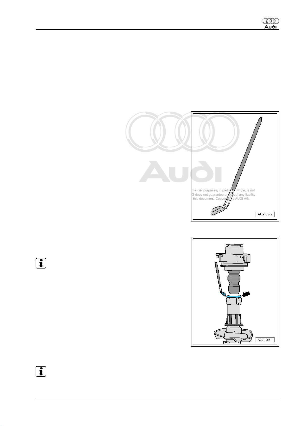
♦ Brush
Coat contact surface -arrow- of plastic cap at suspension strut
protective tube with G 000 405 A2.
Note
After removing the spring inserts/spacers and greasing the cap
for the suspension strut protective tube, make sure that the boot
is correctly seated in the suspension strut mounting and at the
shock absorber tube.
3.2 Reading out: measured value block 32
Note
Only applies in certain countries. For the countries affected, refer
to maintenance table.
3. Description of work 5
Page 10
Protected by copyright. Copying for private or commercial purposes, in part or in whole, is not
permitted unless authorised by AUDI AG. AUDI AG does not guarantee or accept any liability
with respect to the correctness of information in this document. Copyright by AUDI AG.
Audi TT 2007 ➤
Maintenance - Edition 04.2010
– Carry out the following steps, one after the other.
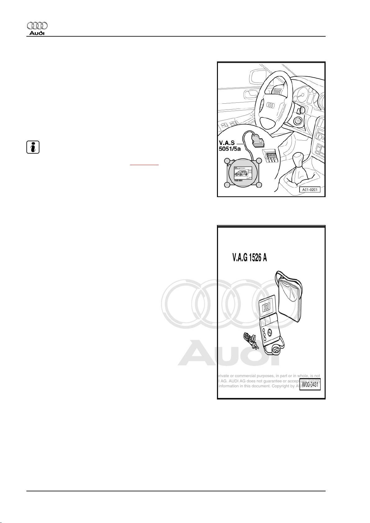
♦ Connect -VAS 5051/5052-
♦ Self-diagnosis
♦ Engine electronics
♦ Measured value blocks
♦ Select measured value block 32
♦ Display zone 2 (4-cyl. engines)
♦ Display zones 2 and 4 (V6 and V8 engines)
Note
Add four times as much G17 additive ⇒ page 21 if there is a
deviation of > 15% in the values.
3.3 Battery: checking "no load" voltage be‐
fore engine is started for first time
3.3.1 Special tools and workshop equipment
required
♦ Hand-held multimeter -V.A.G 1526C-
– Ensure that the following rules are observed, otherwise correct
measurements cannot be guaranteed.
6 3. Description of work
Page 11
Protected by copyright. Copying for private or commercial purposes, in part or in whole, is not
permitted unless authorised by AUDI AG. AUDI AG does not guarantee or accept any liability
with respect to the correctness of information in this document. Copyright by AUDI AG.
♦ The battery must not be placed under load from connected
electrical equipment for at least 12 hours before the test.
♦ The battery must not be charged for at least 12 hours before
test.
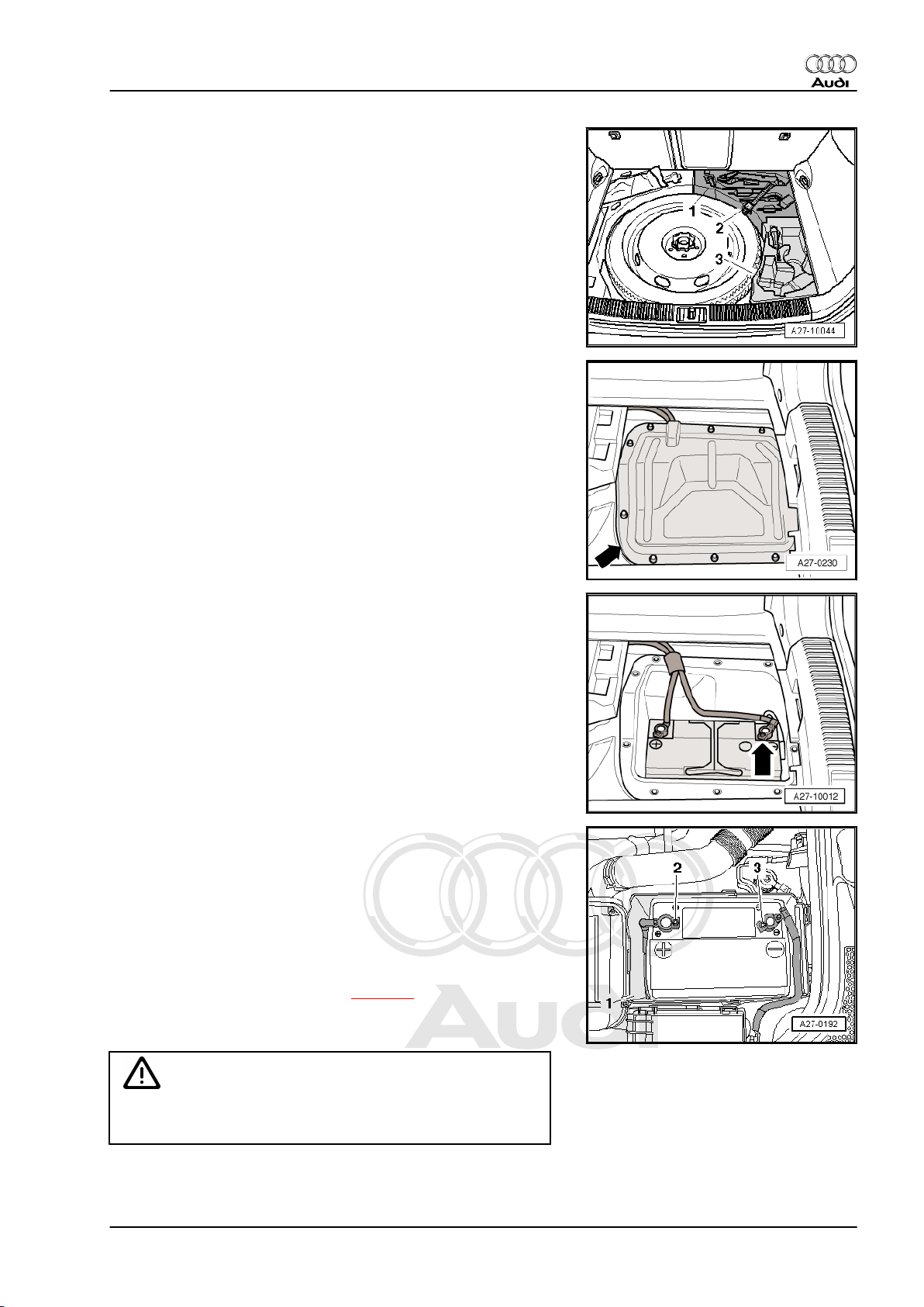
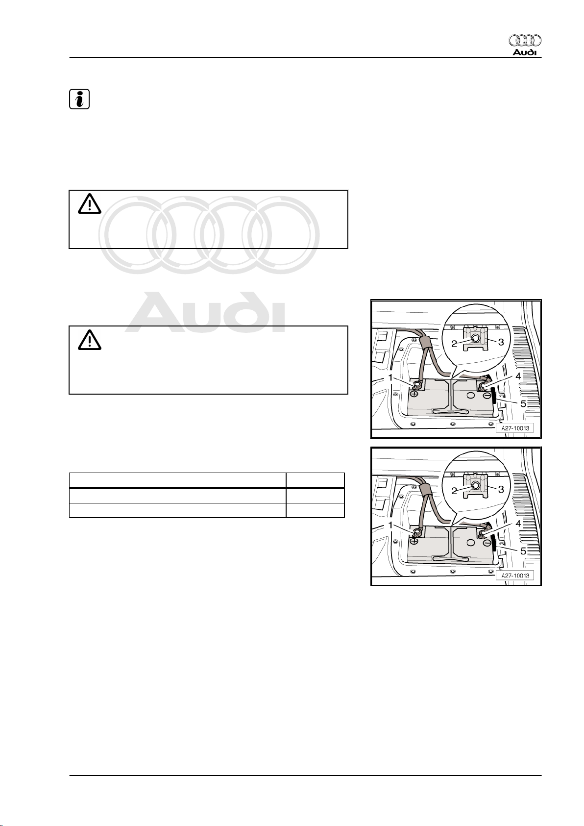
Remove rear moulded insert -3- for tools below luggage com‐
partment floor covering.
– Detach cover -arrow- for battery compartment.
Audi TT 2007 ➤
Maintenance - Edition 04.2010
– Detach moulded insert above battery.
– With ignition switched off, measure voltage between battery
clamps -2- and -3-.
1 - If the tester indicates 12.5 V or more, then the battery is OK.
2 - If the tester indicates 12.2 to 12.5 V the battery must be
charged ⇒ Rep. Gr. 27 .
3 - If the tester indicates between 11.6 and 12.2 V proceed as
follows: Charge battery ⇒ Rep. Gr. 27 . After charging bat‐
tery allow to stand with no load for 24 hours. Then carry out
battery test / battery load test ⇒ page 9 .
4 - If tester indicates 11.6 V or less the battery must be renewed
⇒ Rep. Gr. 27 .
WARNING
Always adhere to correct procedure, otherwise measurements
will be falsified.
3. Description of work 7
Page 12
Protected by copyright. Copying for private or commercial purposes, in part or in whole, is not
permitted unless authorised by AUDI AG. AUDI AG does not guarantee or accept any liability
with respect to the correctness of information in this document. Copyright by AUDI AG.
Audi TT 2007 ➤
Maintenance - Edition 04.2010
3.4 Battery: checking
3.4.1 Batteries with “magic eye”
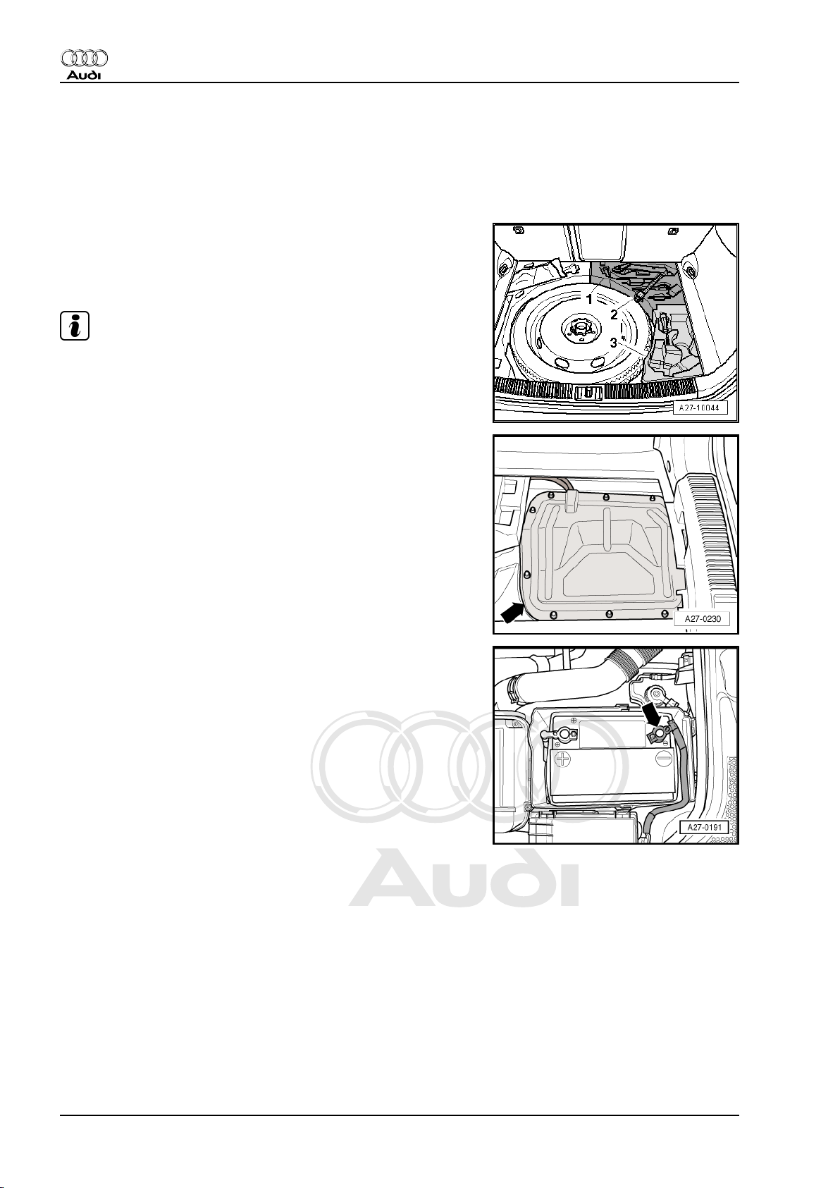
The battery is located in the luggage compartment (rear right).
– Switch off the ignition and remove the ignition key from the
lock.
– Remove rear moulded insert -3- for tools below luggage com‐
partment floor covering.
Note
-Item 1- and -item 2- can be disregarded.
– Detach cover -arrow- for battery compartment.
– Detach moulded insert above battery.
♦ The magic eye -arrow- indicates the electrolyte level and the
charge level of the battery to be checked.
♦ Three different colours are used as indicators:
– Green → the battery is sufficiently charged.
– Black → no charge or charge too low
– Colourless or yellow → critical electrolyte level has been
reached. Battery must be renewed.
3.4.2 Battery with sealing plugs
♦ A visual check of the battery is sufficient for batteries with
clearly visible external min. and max. marks.
♦ The electrolyte level must be above the minimum marking, but
must not exceed the maximum marking.
♦ If the external min. and max. marks on the battery are not
clearly visible or if the electrolyte level cannot be checked
properly due to an opaque battery housing, the sealing plugs
must be unscrewed. It is then possible to visually check the
electrolyte level from the inside.
♦ The electrolyte level must align with the marking inside the
battery (plastic moulding). This corresponds to the max. mark‐
ing on the outside.
8 3. Description of work
Page 13
Protected by copyright. Copying for private or commercial purposes, in part or in whole, is not
permitted unless authorised by AUDI AG. AUDI AG does not guarantee or accept any liability
with respect to the correctness of information in this document. Copyright by AUDI AG.
Note
If electrolyte level is too low, the cell plates dry out, resulting in a
loss of battery capacity (loss of power). The cell plates must be
fully covered by electrolyte (sulphuric acid) in order to prevent
corrosion of plates, plate bridges and cell connectors. Corrosion
of these parts will impair battery function and make it unreliable.
It will be rendered unusable.
WARNING
If the electrolyte level is below the min. marking the battery
must be renewed! ⇒ Rep. Gr. 27
3.5 Battery: checking that battery cables are securely fitted
– Check that battery clamps are securely fitted. If necessary,
tighten nuts -1- and -4-.
Audi TT 2007 ➤
Maintenance - Edition 04.2010
WARNING
If the battery clamp on the positive terminal is not fitted se‐
curely, disconnect the battery earth strap from the battery
negative terminal first to avoid possible accidents.
– Check that battery is securely installed. If necessary tighten
securing bolt -2- on retainer plate -3-.
Tightening torque Nm
Battery clamps to battery terminals 5
Bolt on retainer plate 22
3.6 Battery: performing battery test
Special tools and workshop equipment required
3. Description of work 9
Page 14
Protected by copyright. Copying for private or commercial purposes, in part or in whole, is not
permitted unless authorised by AUDI AG. AUDI AG does not guarantee or accept any liability
with respect to the correctness of information in this document. Copyright by AUDI AG.
Audi TT 2007 ➤
Maintenance - Edition 04.2010
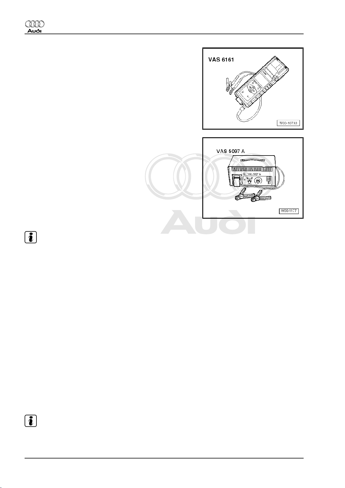
♦ Battery tester -VAS 6161- (with printer)
♦ Battery tester -VAS 5097 A-
Note
♦
During battery test with battery tester -VAS 6161- (with print‐
er), battery earth wire does not have to be disconnected.
♦
It is not necessary to remove the battery when using battery
tester -VAS 5097A- . The battery does not have to be discon‐
nected.
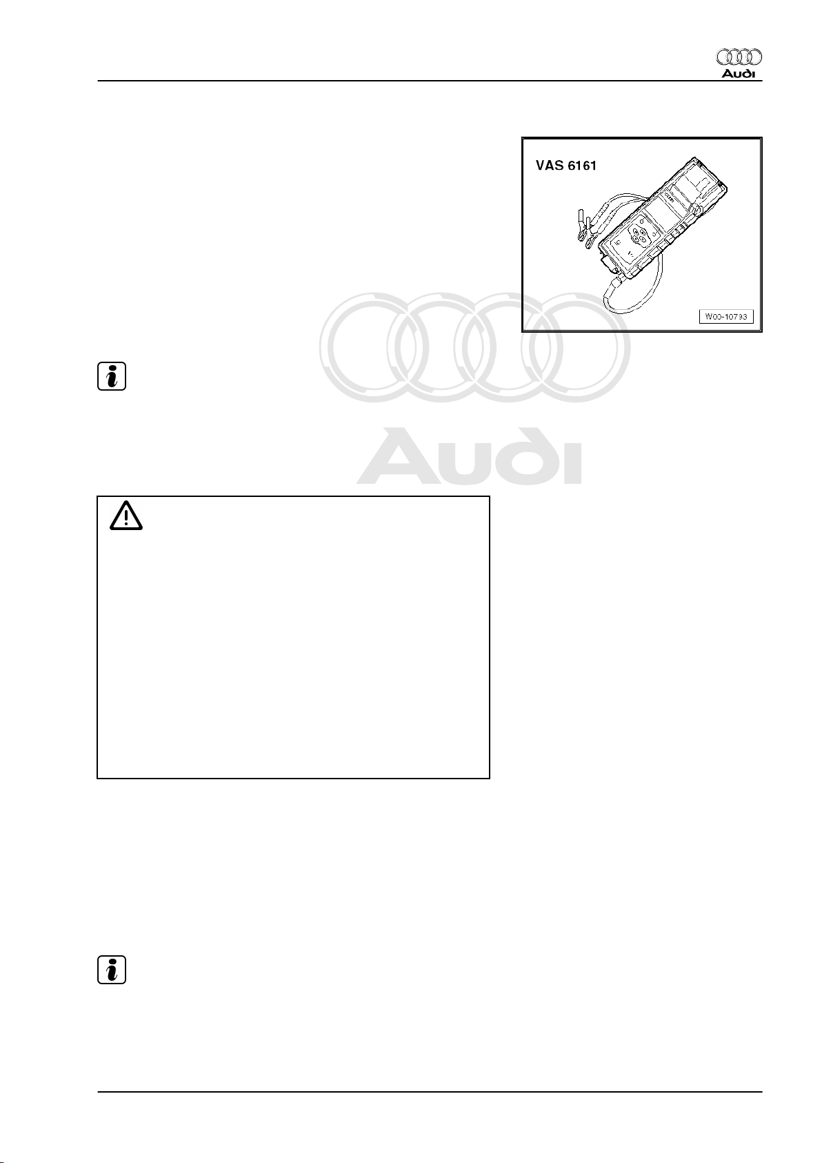
3.6.1 Performing battery test using battery tester -VAS 6161- (with printer)
♦ The battery tester with printer -VAS 6161- no longer puts the
battery under load, but works by measuring the dynamic con‐
ductivity. For this reason it is possible to perform several
measurements without re-charging the battery.
♦ "No-load" voltage measurement can be performed without de‐
lay.
♦ All battery types are stored in the tester. These data can be
updated.
♦ The battery bar code can be directly read off with the optionally
available 2D scanner.
♦ The integrated temperature sensor improves the quality of
measurements.
♦ The data can be stored on an SD card.
Note
For more information on the battery tester -VAS 6161- (with print‐
er), refer to the tester's ⇒ operating instructions .
10 3. Description of work
Page 15
Protected by copyright. Copying for private or commercial purposes, in part or in whole, is not
permitted unless authorised by AUDI AG. AUDI AG does not guarantee or accept any liability
with respect to the correctness of information in this document. Copyright by AUDI AG.
Special tools and workshop equipment required
♦ Battery tester (with printer) -VAS 6161-
Note
For instructions on how to use the battery tester -VAS 6161- refer
to its ⇒ operating instructions .
Procedure:
• The battery temperature must be at least +10 °C.
Audi TT 2007 ➤
Maintenance - Edition 04.2010
WARNING
Risk of injury due to electrolyte.
♦ The accident prevention procedures must be observed
when handling electrolyte.
♦ Wear eye protection and protective clothing.
♦ Sealing plugs of batteries which are not maintenance-free
must be firmly screwed in when measuring voltage under
load.
Risk of explosion due to a discharged battery with “magic eye”.
♦ If the “magic eye” is colourless or light yellow, do not test
or charge the battery. Do not attempt to jump-start the ve‐
hicle! There is a danger of explosion if you test or charge
the battery or jump-start the vehicle! The battery must be
renewed.
– Switch off ignition and all electrical equipment.
– On vehicles with “magic eye” check colour of “magic eye”.
– Switch on battery tester -VAS 6161- (with printer).
– Connect red test clamp “+” of battery tester to positive battery
terminal or jump start terminal in engine compartment.
– Connect black test clamp “–” of battery tester to negative bat‐
tery terminal or jump start terminal in engine compartment.
Note
Make sure the test clamps make proper contact.
– Select one of the following functions:
♦ Maintenance test
3. Description of work 11
Page 16
Protected by copyright. Copying for private or commercial purposes, in part or in whole, is not
permitted unless authorised by AUDI AG. AUDI AG does not guarantee or accept any liability
with respect to the correctness of information in this document. Copyright by AUDI AG.
Audi TT 2007 ➤
Maintenance - Edition 04.2010
♦ Service test
♦ Warranty test
Maintenance test
– Select “Maintenance test” from the menu.
– Connect scanner and scan in vehicle identification number.
– Select connection point: “at battery post” or “at jump start
post”.
– Select vehicle model.
– Scan in battery's bar code.
– Determine temperature by holding temperature sensor at a
distance of approx. 5 cm over battery or jump start post until
a constant temperature is displayed.
– Start test.
– If required, print out test log.
Service test
– Select “Service test” from the menu.
– Select vehicle model.
– Determine temperature by holding temperature sensor at a
distance of approx. 5 cm over battery until a constant temper‐
ature is displayed.
– Select battery type: “Regular”, “AGM”, “2*6V” or “Gel”.
– Select rating units: “CCA”, “JIS”, “DIN”, “SAE”, “IEC” or “EN”.
– Start test.
– If required, print out test log.
Warranty test
– Select “Warranty test” from the menu.
– Select fitting location: “in vehicle” or “out of vehicle”.
– Select vehicle model.
– Determine temperature by holding temperature sensor at a
distance of approx. 5 cm over battery until a constant temper‐
ature is displayed.
– Select battery type: “Regular”, “AGM”, “2*6V” or “Gel”.
– Select corresponding rating using arrow buttons.
– Start test.
– If required, print out test log.
Note
The test log is required for warranty processing.
– Switch off battery tester.
– Detach test clamps.
12 3. Description of work
Page 17
Protected by copyright. Copying for private or commercial purposes, in part or in whole, is not
permitted unless authorised by AUDI AG. AUDI AG does not guarantee or accept any liability
with respect to the correctness of information in this document. Copyright by AUDI AG.
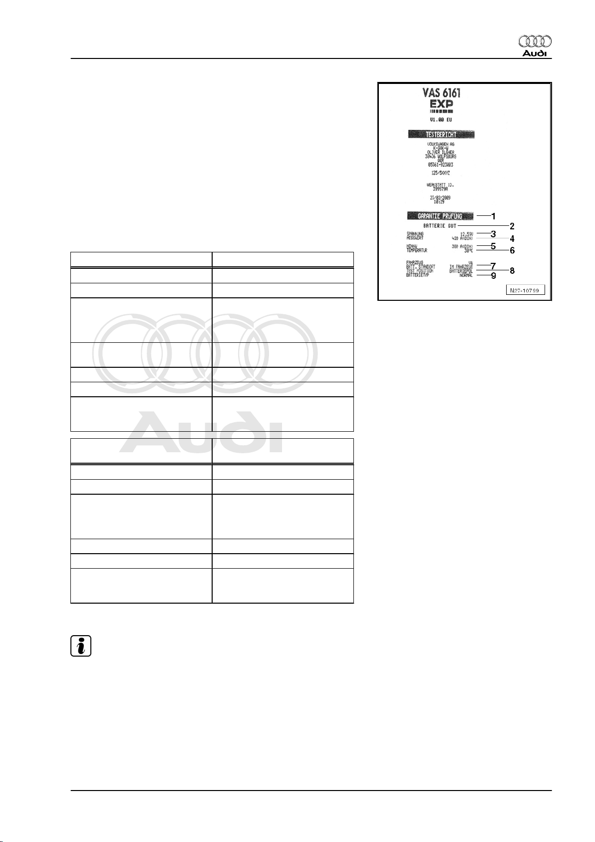
Test result on printout:
1 - Test mode
2 - Test result
3 - Measured voltage
4 - Measured nominal value of battery
5 - Nominal value of battery set on tester
6 - Temperature measured above battery
7 - Fitting location of battery
8 - Position of battery clamp set on tester
9 - Selected battery type
Result of maintenance test Measures
Battery good Battery OK
Charge battery Charge battery
Charge battery instantly Charge battery completely and
repeat test. Faults can occur if
battery is not completely charg‐
ed when test is repeated
Mark as defect Mark as “defect” and remove
from vehicle
Check tester connection Remove battery and repeat test
Battery frozen Thaw battery and repeat test
Check connection Connect cable directly to bat‐
tery and not to jump-start termi‐
nal
Audi TT 2007 ➤
Maintenance - Edition 04.2010
Result of service test and war‐
Measures
ranty test
Battery good Battery OK
Battery good - recharge Charge battery completely
Replace battery Remove battery and repeat
test. Result "Replace battery"
can arise if cables do not make
proper contact
Bad cell - replace Renew battery
Battery frozen Thaw battery and repeat test
Check connection Connect cable directly to bat‐
tery and not to jump-start termi‐
nal
– Renew battery ⇒ Rep. Gr. 27 .
Note
If the battery has to be renewed, observe disposal regulations.
3.6.2 Performing battery load test using VAS 5097 A
– Switch off ignition.
– Read operating instructions for battery tester.
3. Description of work 13
Page 18
Protected by copyright. Copying for private or commercial purposes, in part or in whole, is not
permitted unless authorised by AUDI AG. AUDI AG does not guarantee or accept any liability
with respect to the correctness of information in this document. Copyright by AUDI AG.
Audi TT 2007 ➤
Maintenance - Edition 04.2010
– Connect the clamps of the test leads to battery terminals as
described in operating instructions for the tester.
The clamps must make good contact with the battery terminals.
– As the load current differs depending on the battery, the cur‐
rent must be set on the tester according to battery capacity ⇒
Operating instructions for battery test equipment.
– Perform a battery load test as described in the operating in‐
structions.
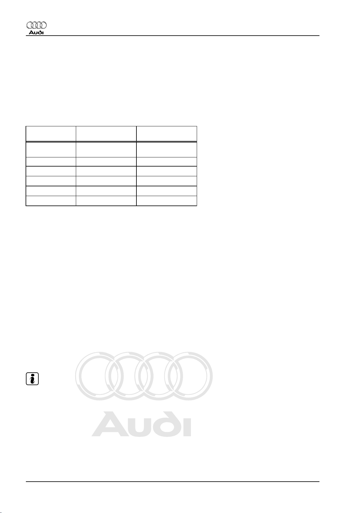
Please note the test results shown on the display of the tester.
Display on bat‐
tery tester
Battery Very
Delivery Inspection Inspection Service
LongLife Service
Battery OK Battery OK
Good
Battery Good Battery OK Battery OK
Battery Sufficient Renew battery
Battery Not Good Renew battery
Battery Faulty Renew battery
Cannot be tested Renew battery
Charge battery
Charge battery
Renew battery
Renew battery
1)
1)
2)
2)
1) - Perform battery load test again after recharging the battery.
If tester shows “Battery Good” after charging, battery is OK. How‐
ever, if tester still shows “Battery Not Good”, battery must be
renewed.
2) - Agree battery replacement with customer.
– Renew battery ⇒ Rep. Gr. 27 .
Notes on battery load test:
The battery voltage will decrease during the test due to the high
load (high current flow).
If a battery is in working order battery voltage will only drop to
minimum voltage.
If the battery is defective or only insufficiently charged, battery
voltage will very quickly drop below minimum voltage.
After carrying out the load test the voltage will remain at this low
level for quite a while; voltage will only rise again slowly.
3.7 Tyres: checking condition, wear pattern,
tread depth and correcting tyre pres‐
sures
Note
All tyres and wheels (front and rear) must be of same type and
size. On four-wheel drive vehicles you must also ensure that all
tyres are made by the same manufacturer and have the same
tread pattern.
Delivery Inspection
– Check tyre tread surfaces and sidewalls for damage and re‐
move any foreign bodies.
Inspection Service
– Check tyres for scuffing, one-sided wear, porous sidewalls,
cuts and fractures.
14 3. Description of work
Page 19
Protected by copyright. Copying for private or commercial purposes, in part or in whole, is not
permitted unless authorised by AUDI AG. AUDI AG does not guarantee or accept any liability
with respect to the correctness of information in this document. Copyright by AUDI AG.
WARNING
Any defects must be reported to the customer.
Checking tyre wear pattern
– The wear pattern of the front tyres indicates, for example,
whether the toe and camber have to be checked.
♦ Feathering on tread indicates incorrect toe setting.
♦ One-sided tread wear is usually due to incorrect camber.
Note
If the above types of wear are found, check wheel alignment to
determine the cause (repair measure).
Checking tyre tread depth
♦ Minimum depth: 1.6 mm
Audi TT 2007 ➤
Maintenance - Edition 04.2010
Note
♦
This figure may vary for individual countries due to different
legislation.
♦
If the tread depth is approaching the minimum permissible
tread depth, the customer must be informed.
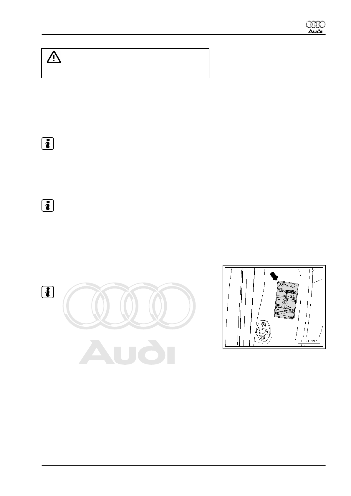
3.7.1 Inflating to correct pressures
The correct inflation pressures are listed on the sticker inside the
B-pillar.
Note
Please note that the tyre pressures listed on the sticker apply to
cold tyres. When the tyres are warm, the actual pressures will be
higher, but must not be reduced.
3.7.2 Spare wheel
• Collapsible spare wheel
The correct tyre pressure is indicated on the sidewall.
3.8 Brake system: visual check for leaks and damage
– Check following components for leaks and damage:
♦ Brake master cylinder
♦ Brake servo
♦ ABS hydraulic unit
♦ Brake calipers
3. Description of work 15
Page 20
Protected by copyright. Copying for private or commercial purposes, in part or in whole, is not
permitted unless authorised by AUDI AG. AUDI AG does not guarantee or accept any liability
with respect to the correctness of information in this document. Copyright by AUDI AG.
Audi TT 2007 ➤
Maintenance - Edition 04.2010
– Ensure that brake hoses are not twisted.
– Make sure that brake hoses do not touch any components
when steering is on full lock.
– Check brake hoses for porosity, blistering and brittleness.
– Check brake hoses and pipes for chafing.
– Check brake pipe connections and mountings for correct seat‐
ing, leaks and corrosion.
WARNING
Any faults found must be rectified (repair measure).
3.9 Lights: checking function
– The following components must be checked:
♦ Front lights: side lights, dipped beam, main beam, front fog
lights, turn signals, hazard warning lights
♦ Tail light cluster: brake lights (incl. 3rd brake light), rear lights,
reversing lights, rear fog light, number plate light, turn signals,
hazard warning lights
♦ Horn, glove box light and luggage compartment light
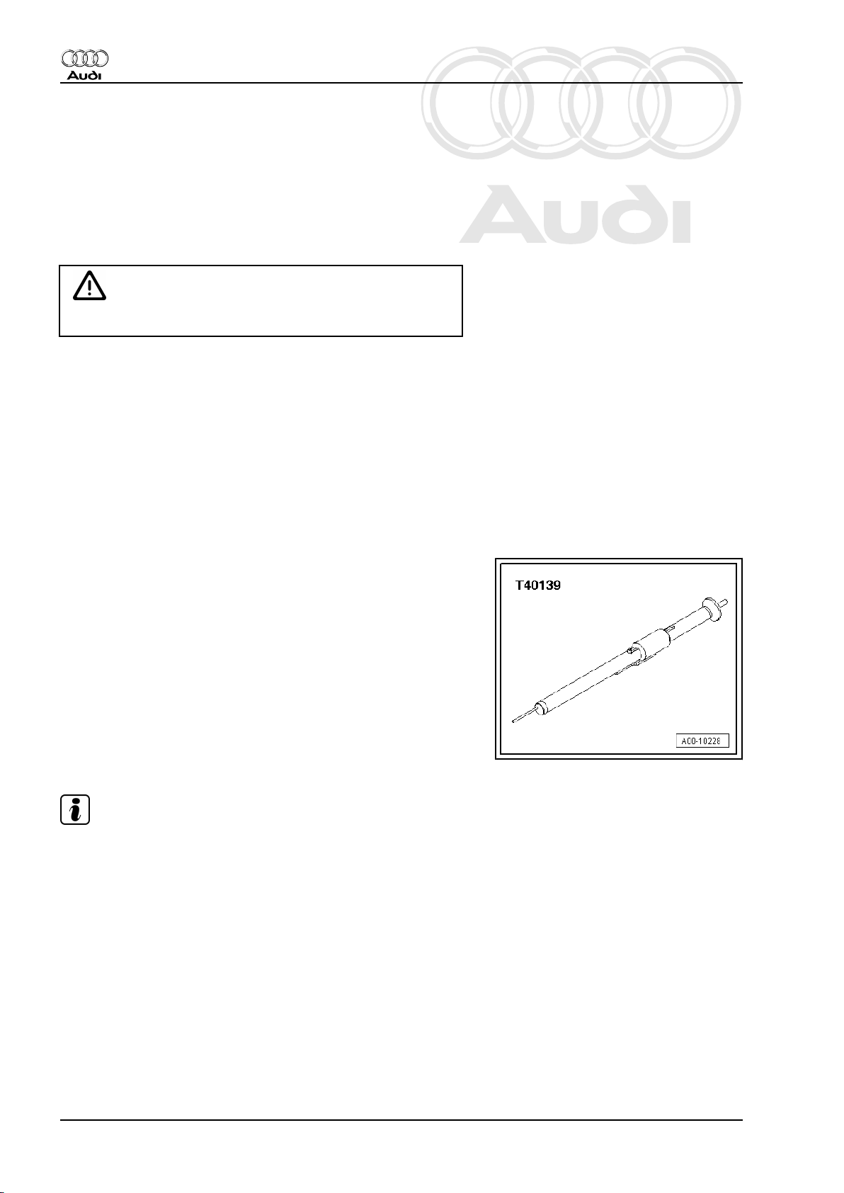
3.10 Brake pads: checking thickness
Special tools and workshop equipment required
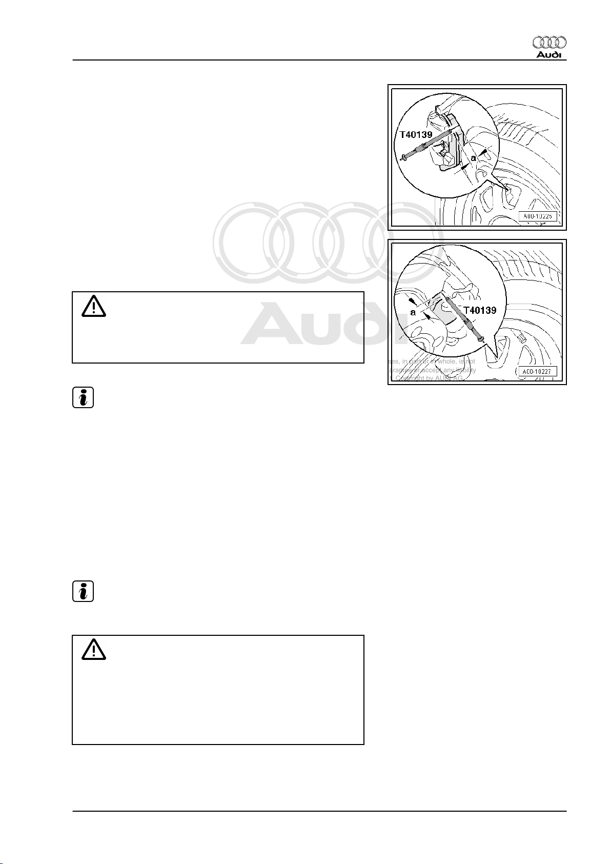
♦ Test pin T40139
Test pin
Before using the test gauge to check the pad thickness, push the
sliding ring towards the tip of the gauge as far as it will go.
Then insert the test gauge through the wheel rim and bring the tip
of the gauge into contact with the brake disc. Then slide the body
of the gauge uniformly towards the brake pad until the gauge
makes contact with the backplate of the brake pad.
Then take out the test pin and read off the value on the scale
marked with the brake symbol.
Note
♦
When removing the test pin, take care not to move the sliding
ring. This would give an incorrect measurement.
♦
The second scale on the test pin (with the tyre symbol) can be
used for checking tread depth.
16 3. Description of work
Page 21
Protected by copyright. Copying for private or commercial purposes, in part or in whole, is not
permitted unless authorised by AUDI AG. AUDI AG does not guarantee or accept any liability
with respect to the correctness of information in this document. Copyright by AUDI AG.
Front disc brake pads:
a - Pad thickness including backplate
- Wear limit: 7
Rear disc brake pads:
a - Pad thickness including backplate
- Wear limit: 7
WARNING
When brake pad thickness (including backplate) is down to 7,
the brake pads have reached their wear limit and must be re‐
newed (repair measure). The customer must be informed.
Audi TT 2007 ➤
Maintenance - Edition 04.2010
Note
♦
On some vehicles (fitted with aftermarket rims) it may not be
possible to insert the test pin through the wheel rim and bring
it into contact with the brake disc or the brake pad, due to the
shape of the rim. In this case proceed as follows:
♦
Determine thickness of outer pads by checking visually (using
electric torch through cut-out in rim).
♦
Determine thickness of inner pads by checking visually (with
help of electric torch and mirror).
3.11 Brake fluid level (depends on brake pad wear): checking
Note
Only use new genuine VW/Audi brake fluid, refer to ETKA.
WARNING
♦ Brake fluid is poisonous. It also has caustic properties and
must therefore not be allowed to come into contact with
paintwork.
♦ Brake fluid is hygroscopic, i.e. it absorbs moisture from the
surrounding air. It must therefore always be stored in airtight containers.
– Note the following:
3. Description of work 17
Page 22
Protected by copyright. Copying for private or commercial purposes, in part or in whole, is not
permitted unless authorised by AUDI AG. AUDI AG does not guarantee or accept any liability
with respect to the correctness of information in this document. Copyright by AUDI AG.
Audi TT 2007 ➤
Maintenance - Edition 04.2010
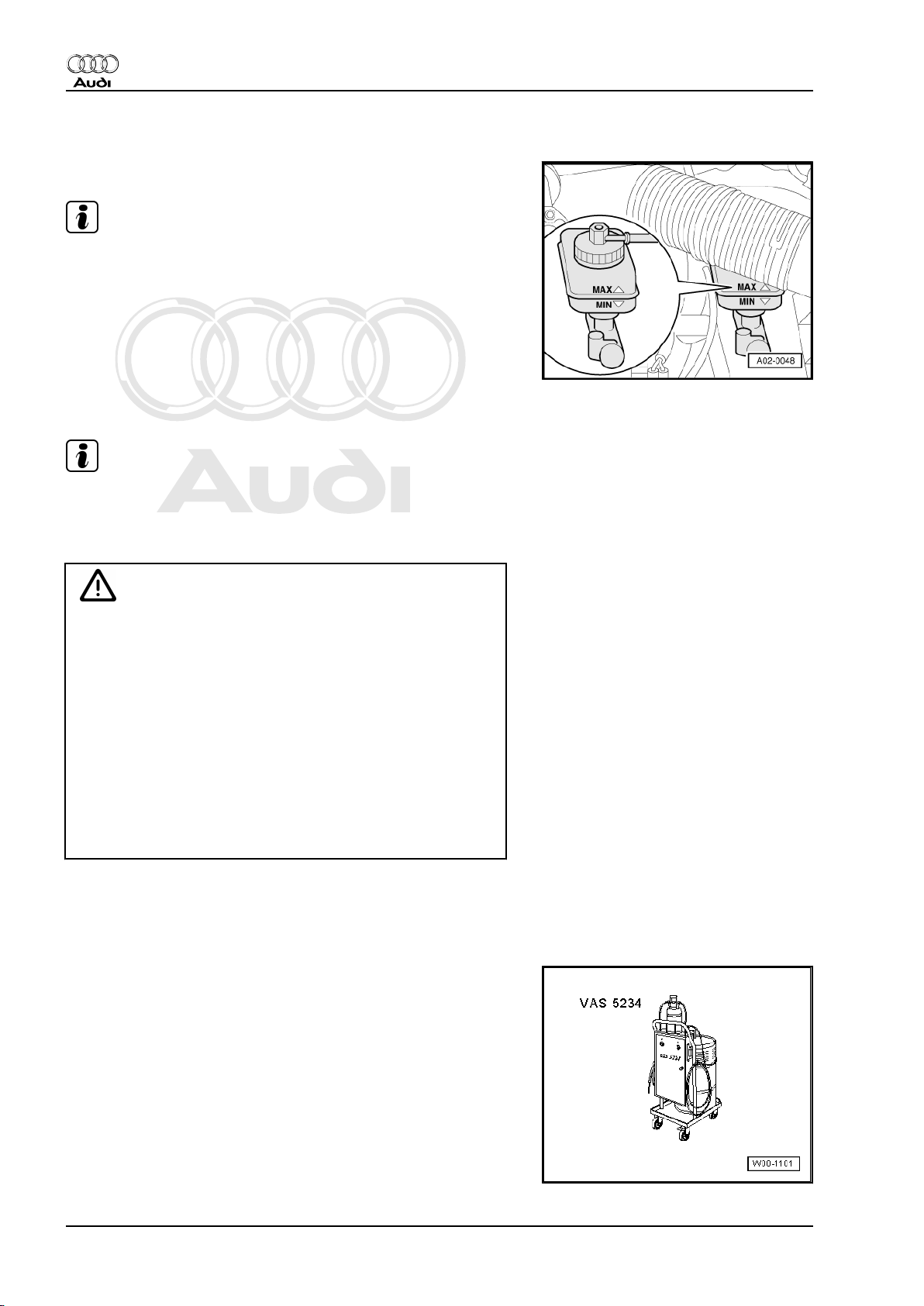
3.11.1 Delivery Inspection
♦ The fluid level must be at the MAX mark.
Note
The fluid level must not exceed the MAX marking, otherwise the
fluid will overflow.
3.12 Brake fluid: changing
Note
Only use new genuine VW/Audi brake fluid, refer to ETKA.
Changing brake fluid with brake filling and bleeding equipment VAS 5234-
WARNING
♦ Brake fluid must on no account come into contact with liq‐
uids containing mineral oils (oil, petrol, cleaning agents).
Mineral oils damage the plugs and sleeves in the brake
system.
♦ Brake fluid is poisonous and must under no circumstances
be sucked through a tube using the mouth. Because of its
caustic properties it must also not come into contact with
paintwork.
♦ Brake fluid is hygroscopic, i.e. it absorbs moisture from the
surrounding air. It must therefore always be stored in airtight containers.
♦ Always observe the relevant environmental regulations for
disposal.
3.12.1 Changing brake fluid with brake filling and bleeding equipment -VAS 5234-
Special tools and workshop equipment required
♦ Brake filling and bleeding equipment -VAS 5234-
18 3. Description of work
Page 23
Protected by copyright. Copying for private or commercial purposes, in part or in whole, is not
permitted unless authorised by AUDI AG. AUDI AG does not guarantee or accept any liability
with respect to the correctness of information in this document. Copyright by AUDI AG.
♦ Container for collecting used fluid
Audi TT 2007 ➤
Maintenance - Edition 04.2010
Note
♦
The brake fluid reservoir must always be adequately filled to
ensure that no air can enter the brake system from the reser‐
voir.
♦
The strainer in the brake fluid reservoir must not be removed.
♦
Observe the instructions given in the operating manual for the
brake filling and bleeding equipment -VAS 5234- .
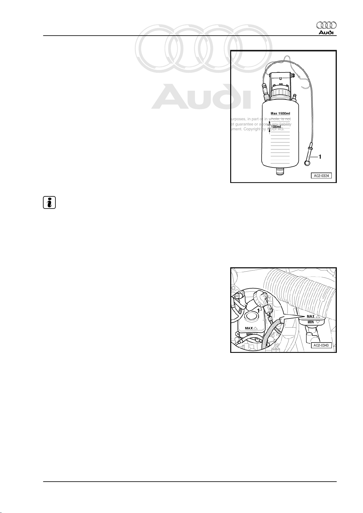
– Unscrew cap -1- from brake fluid reservoir.
3. Description of work 19
Page 24

Protected by copyright. Copying for private or commercial purposes, in part or in whole, is not
permitted unless authorised by AUDI AG. AUDI AG does not guarantee or accept any liability
with respect to the correctness of information in this document. Copyright by AUDI AG.
Audi TT 2007 ➤
Maintenance - Edition 04.2010
– Use extraction hose included in brake filling and bleeding
equipment -VAS 5234- to extract as much brake fluid as pos‐
sible.
WARNING
Do not reuse the old brake fluid that has been extracted.
– Connect adapter -1- to brake fluid reservoir.
– Connect filling hose -2- included with brake filling and bleeding
equipment -VAS 5234- to adapter.
Vehicles with manual gearbox:
– Remove cap from bleeder screw on clutch slave cylinder.
– Connect bleeder hose -1- attached to collector bottle to bleed‐
er screw on clutch slave cylinder, open bleeder screw and let
approx. 100 ml flow out. Close bleeder screw and fit cap back
on.
– Repeatedly depress the clutch pedal.
Continuation for all vehicles:
– Remove caps from bleeder screws.
– Connect bleeder hose -1- attached to collector bottle to bleed‐
er screw (front left), open bleeder screw and allow approx. 200
ml of brake fluid to flow out. Close bleeder screw.
20 3. Description of work
Page 25

Protected by copyright. Copying for private or commercial purposes, in part or in whole, is not
permitted unless authorised by AUDI AG. AUDI AG does not guarantee or accept any liability
with respect to the correctness of information in this document. Copyright by AUDI AG.
– Repeat the procedure on the other front side of the vehicle.
– Connect bleeder hose -1- attached to collector bottle to bleed‐
er screw (rear left), open bleeder screw and allow approx. 200
ml of brake fluid to flow out. Close bleeder screw.
– Repeat the procedure on the other rear side of the vehicle.
– Fit caps back on bleeder screws on brake calipers.
– Move filling lever on brake filling and bleeding equipment -
VAS 5234- to position -B- (see operating instructions).
– Detach filling hose from adapter.
– Unscrew adapter from brake fluid reservoir.
– Screw cap onto brake fluid reservoir.
– Check brake fluid level and correct as necessary.
– Check pedal pressure and free play of brake pedal. Free play:
no more than 1/3 of pedal travel
3.12.2 Table - sequence for changing brake flu‐
id / quantities
Audi TT 2007 ➤
Maintenance - Edition 04.2010
Front left 200 ml
Front right 200 ml
Rear left 200 ml
Rear right 200 ml
Clutch slave cylinder 200 ml
Total quantity 1000 ml
3.13 S tronic gearbox: changing oil and re‐
newing oil filter
– Change gear oil ⇒ Rep. Gr. 00 ; Direct shift gearbox .
3.14 Electric windows: checking positions
The electric window regulators “forget” their current positions and
the automatic open/close function when the battery is disconnec‐
ted.
– Activate the automatic open/close function as follows:
– Switch on ignition.
– Close the windows all the way to their top positions using the
window switches.
– Then operate all window switches again for at least one sec‐
ond in the “close” direction to activate the automatic one-touch
function.
– Press switch to open window. The side window should move
all the way down automatically.
3.15 G17 additive: adding
Note
Only applies in certain countries. For the countries affected, refer
to maintenance table.
3. Description of work 21
Page 26

Protected by copyright. Copying for private or commercial purposes, in part or in whole, is not
permitted unless authorised by AUDI AG. AUDI AG does not guarantee or accept any liability
with respect to the correctness of information in this document. Copyright by AUDI AG.
Audi TT 2007 ➤
Maintenance - Edition 04.2010
♦ When adding G17 additive into the tank, the ratio must be
10 ml of additive per 10 litres of fuel.
♦ The following table lists the quantities to be added depending
on the fuel level indicated on the fuel gauge.
Mixture ratio:
Indicated on fuel gauge G17 fuel additive
approx. 1/4 approx. 15 ml
approx. 1/2 approx. 30 ml
approx. 3/4 approx. 45 ml
approx. 1/1 approx. 60 ml
Note
♦
The quantities listed in the table refer to a fuel tank with a ca‐
pacity of 60 litres.
♦
If the fuel level in the fuel tank is other than quoted in the table,
add additive in steps of 10 ml additive per 10 litres of fuel.
3.16 Ignition keys: checking operation
– Open key ring to check each key individually.
– Insert one ignition key after the other into ignition lock and start
engine with each key.
– If the engine switches off automatically after approx. 3 sec‐
onds and the odometer display shows “safe” the ignition key
has not been matched to the immobiliser.
– Repair measure: Guided Fault Finding (matching ignition
keys).
– Make a note in the delivery record of the number of ignition
keys which have been checked and handed over.
3.17 Diesel particulate filter: reading out ash deposit mass
Note
Engines affected: see Maintenance table.
– Carry out the following steps, one after the other.
22 3. Description of work
Page 27

Protected by copyright. Copying for private or commercial purposes, in part or in whole, is not
permitted unless authorised by AUDI AG. AUDI AG does not guarantee or accept any liability
with respect to the correctness of information in this document. Copyright by AUDI AG.
♦ Connect VAS 5051 or 5052.
♦ Guided Functions
♦ Read measured values
♦ Oil ash deposits
♦ Maximum value for ash deposit mass (4-cyl. engines): 60 g
Note
If ash deposit mass is <= 60 g the vehicle can be driven for a
further 30,000 km (19,000 miles).
WARNING
If ash deposit mass value is 60 g or greater for 4-cyl. engines,
the diesel particulate filter must be renewed.
3.18 Data memory: interrogating with vehicle
diagnostic, testing and information sys‐
tem -VAS 5051/ 5052-
Audi TT 2007 ➤
Maintenance - Edition 04.2010
– Carry out the following steps, one after the other.
♦ Connect VAS 5051 or 5052.
♦ Vehicle Self-Diagnosis
♦ Gateway - Fitting list
♦ Read out control units for which entries have been made in
fault memory.
♦ Eliminate relevant faults (when approved by customer).
3.19 Noise insulation: removing and installing
– Remove noise insulation -fasteners 1 ... 4-.
3. Description of work 23
Page 28

Protected by copyright. Copying for private or commercial purposes, in part or in whole, is not
permitted unless authorised by AUDI AG. AUDI AG does not guarantee or accept any liability
with respect to the correctness of information in this document. Copyright by AUDI AG.
Audi TT 2007 ➤
Maintenance - Edition 04.2010
3.20 Haldex coupling: changing oil
– Change oil: ⇒ Rep. Gr. 39 .
3.21 Poly V-belt: renewing
Vehicles with 4-cyl. petrol engine 2.0 ltr. TFSI:
– Removing and installing poly V-belt ⇒ Rep. Gr. 13
Vehicles with 6-cyl. petrol engine 3.2 ltr. MPI:
– Removing and installing poly V-belt ⇒ Rep. Gr. 13
Vehicles with 5-cyl. petrol engine 2.5 ltr. TFSI:
– Removing and installing poly V-belt ⇒ Rep. Gr. 13
Vehicles with 4-cyl. diesel engine 2.0 ltr. TDI CR:
– Removing and installing poly V-belt ⇒ Rep. Gr. 13
3.22 Fuel filter: renewing (2.0 ltr. TDI CR)
Special tools and workshop equipment required
♦ Diesel extractor -VAS 5226-
Note
♦
Please ensure that no diesel fuel makes contact with the cool‐
ant hoses.
♦
If necessary, clean hoses immediately.
♦
Observe disposal regulations.
♦
Follow the procedure shown below:
– Unscrew bolt from drain pipe -1-.
– Attach diesel extractor -VAS 5226- to connection.
– Use diesel extractor -VAS 5226- to draw off about 100 ml of
diesel fuel.
– Renew seal and screw bolt into drain pipe.
– Loosen all bolts on cover -arrows- in diagonal sequence (ap‐
prox. 1.5 to 2 turns).
24 3. Description of work
Page 29

Protected by copyright. Copying for private or commercial purposes, in part or in whole, is not
permitted unless authorised by AUDI AG. AUDI AG does not guarantee or accept any liability
with respect to the correctness of information in this document. Copyright by AUDI AG.
– Unscrew bolts completely and remove cover from filter.
– Remove filter element -1- and seals -2 and 3- from filter hous‐
ing -4-.
Audi TT 2007 ➤
Maintenance - Edition 04.2010
– Renew seals -3-.
– Install new filter element.
– Install new seal -2- on cover of filter.
– Fit cover with seal onto filter housing.
3. Description of work 25
Page 30

Protected by copyright. Copying for private or commercial purposes, in part or in whole, is not
permitted unless authorised by AUDI AG. AUDI AG does not guarantee or accept any liability
with respect to the correctness of information in this document. Copyright by AUDI AG.
Audi TT 2007 ➤
Maintenance - Edition 04.2010
– Pre-tighten bolts in diagonal sequence (2 turns).
Note
The bolts have to be tightened diagonally in correct sequence.
Otherwise, the cover will tilt on the centre pipe and the cover and
seal could get damaged.
– Tighten bolts in sequence shown.
– Start engine and check fuel system for leaks (visual check).
Tightening torques Nm
Bolts on filter housing 5
Note
Observe disposal regulations.
3.23 Cooling system: checking coolant addi‐
tive level and topping up with coolant if
necessary
Note
♦
The coolant additive ratio must be at least 40 % (gives anti‐
freeze protection down to –25 °C), but should not exceed 60 %
(frost protection down to –40 °C); beyond this concentration
both the frost protection and the cooling efficiency are reduced
again.
♦
Frost protection should be ensured down to temperatures of
about –25 °C.
♦
For approved coolant additive, refer to ⇒ ETKA .
Special tools and workshop equipment required
♦ Refractometer -T10007-
26 3. Description of work
Page 31

Protected by copyright. Copying for private or commercial purposes, in part or in whole, is not
permitted unless authorised by AUDI AG. AUDI AG does not guarantee or accept any liability
with respect to the correctness of information in this document. Copyright by AUDI AG.
Note
For exact readings for the following tests refer to the light-dark
border. Before carrying out the tests, you can first determine the
light-dark border for water. To do so, use a pipette to place a drop
of water on the glass. The light-dark border will now show up
clearly at the “WATERLINE” marking.
– Check the coolant additive concentration using the refractom‐
eter -T10007- . Observe the instructions in the operating man‐
ual.
Scale -1- on the refractometer applies to coolant additives G 12,
G 12 Plus, G 12 Plus Plus and G 11.
Scale -2- refers only to coolant additive -G 13- (previously called
L80).
Note
♦
Frost protection should be ensured down to temperatures of
about –25 °C.
♦
If greater frost protection is required in very cold climates, the
proportion of coolant additive can be increased, but only up to
60 % (this gives frost protection at temperatures down to ap‐
prox. -40 °C). Beyond this concentration the frost protection
and also the cooling efficiency are reduced again.
Audi TT 2007 ➤
Maintenance - Edition 04.2010
Checking coolant level and topping up with coolant if necessary
– Check coolant level in coolant expansion tank while the engine
is cold.
3. Description of work 27
Page 32

Protected by copyright. Copying for private or commercial purposes, in part or in whole, is not
permitted unless authorised by AUDI AG. AUDI AG does not guarantee or accept any liability
with respect to the correctness of information in this document. Copyright by AUDI AG.
Audi TT 2007 ➤
Maintenance - Edition 04.2010
♦ Delivery Inspection: Coolant level should be above “Min.”
marking -arrow-
♦ Inspection Service: Coolant level should be above “Min.”
marking -arrow-
– If coolant level is too low, add required amount (using correct
mixture ratio).
Note
If fluid losses are greater than can be reasonably expected, de‐
termine the cause and rectify faults (repair measure).
Mixture ratio:
Frost protectiontoCoolant additive Water
–25 °C approx. 40 % approx. 60 %
–35 °C approx. 50 % approx. 50 %
–40 °C approx. 60 % approx. 40 %
Note
♦
Coolant additives prevent frost and corrosion damage, scaling
and also raise the boiling point of the coolant. It is therefore
essential to use the correct coolant additive in the cooling sys‐
tem all year round.
♦
Because of its high boiling point, the coolant improves engine
reliability under heavy loads, particularly in countries with trop‐
ical climates.
♦
The coolant concentration must not be reduced by adding wa‐
ter even in warmer seasons and in warmer countries. The
antifreeze ratio must be at least 40 %.
3.24 Instrument cluster: setting the language
– Carry out the following steps, one after the other.
♦ Connect VAS 5051 or 5052.
♦ Guided Fault Finding/Guided Functions
♦ Go to - Function / component selection
♦ Servicing
♦ Adapting the language
♦ Follow the instructions shown on the screen.
28 3. Description of work
Page 33

Protected by copyright. Copying for private or commercial purposes, in part or in whole, is not
permitted unless authorised by AUDI AG. AUDI AG does not guarantee or accept any liability
with respect to the correctness of information in this document. Copyright by AUDI AG.
3.25 Air cleaner: cleaning housing and re‐
newing filter element
3.25.1 6-cyl. petrol engine 3.2 MPI
– Open hose clip -2- with hose clip pliers -V.A.G 1921- and re‐
move intake hose -1-.
– Release and detach connector -3- from air mass meter.
– Remove securing bolts -arrows-.
– Lift out air cleaner housing (top section).
– Take out old filter element -arrow-.
– Clean filter housing and install new filter element.
Audi TT 2007 ➤
Maintenance - Edition 04.2010
– Install air cleaner housing (top section) and tighten bolts -ar‐
rows-.
– Fit connector -3- onto air mass meter and make sure it en‐
gages.
– Fit intake hose -1- onto air cleaner housing and secure with
hose clip -2-.
Important: observe general notes at the end of the section
⇒ page 36
3.25.2 4-cyl. petrol engine 2.0 ltr. TFSI
Special tools and workshop equipment required
3. Description of work 29
Page 34

Protected by copyright. Copying for private or commercial purposes, in part or in whole, is not
permitted unless authorised by AUDI AG. AUDI AG does not guarantee or accept any liability
with respect to the correctness of information in this document. Copyright by AUDI AG.
Audi TT 2007 ➤
Maintenance - Edition 04.2010
♦ Spring-type clip pliers -VAS 5024-
– Unplug electrical connector -3- from air mass meter -G70- .
– Open clamps -1 and 2- and disconnect air hose from air mass
meter.
– Unclip intake hose -arrows-.
– Release spring-type clips -4- and detach air intake hose from
engine cover panel.
– Carefully pull engine cover panel off at positions
-1 - 2 - 3 - 4- one after another.
Caution
Always observe this sequence (risk of breaking engine cover
panel).
– Cover open intake hose with a clean cloth.
Removing air filter element
– Unscrew all bolts -arrows-.
30 3. Description of work
Page 35

Protected by copyright. Copying for private or commercial purposes, in part or in whole, is not
permitted unless authorised by AUDI AG. AUDI AG does not guarantee or accept any liability
with respect to the correctness of information in this document. Copyright by AUDI AG.
– Detach engine cover panel (note retainers -arrows-).
– Pull air filter element out of engine cover panel.
– Clean filter housing and install new filter element.
Note
♦
Self-tapping screws are used in production to secure the top
section of the air cleaner to the bottom section. If these screws
are tightened or loosened with a power screwdriver the thread
in the top section of the air cleaner housing can be damaged.
♦
For this reason, a power screwdriver must ONLY be used if
the following requirements are met:
♦
Power screwdriver: max. 200 rpm.
♦
It must be possible to set the max. tightening torque to 3 Nm.
♦
To install the engine cover panel, first align it at the four mount‐
ing points. Then use the flat surface of your hands to fit the
cover onto the engine evenly, pressing downwards onto the
four mounting points simultaneously.
♦
When installing the engine cover panel, make sure the rubber
sleeve is properly seated between the air cleaner housing and
the engine intake.
Audi TT 2007 ➤
Maintenance - Edition 04.2010
– Assembly is conducted in reverse sequence.
Important: observe general notes at the end of the section
⇒ page 36
3. Description of work 31
Page 36

Protected by copyright. Copying for private or commercial purposes, in part or in whole, is not
permitted unless authorised by AUDI AG. AUDI AG does not guarantee or accept any liability
with respect to the correctness of information in this document. Copyright by AUDI AG.
Audi TT 2007 ➤
Maintenance - Edition 04.2010
3.25.3 4-cyl. petrol engine 2.0 ltr. TFSI
Removing
– Disconnect air hose -1- from air mass meter -G70- .
– Unplug electrical connector -2- from air mass meter -G70- .
– Detach air cleaner (top section) -arrows- and remove air filter
element.
Installing
Installation is performed in reverse sequence; note the following:
To ensure the correct function of the air mass meter it is important
to observe the following notes and adhere to the procedures de‐
scribed below.
Note
♦
If the air filter element is very dirty or wet, dirt particles or water
can reach the air mass meter and falsify the detected air mass
values. This will cause a loss of power, as the calculated in‐
jection quantities will be too low.
♦
Always use genuine air filter elements (same as original equip‐
ment).
♦
The air cleaner housing must always be clean.
♦
Secure all hose connections with genuine hose clips (same as
original equipment) ⇒ Electronic parts catalogue .
♦
When cleaning the air cleaner housing with compressed air,
cover the critical components of the engine intake system such
as the air mass meter and intake pipes etc. with a clean cloth
to avoid malfunctioning.
♦
Observe disposal regulations.
32 3. Description of work
Page 37

Protected by copyright. Copying for private or commercial purposes, in part or in whole, is not
permitted unless authorised by AUDI AG. AUDI AG does not guarantee or accept any liability
with respect to the correctness of information in this document. Copyright by AUDI AG.
– Blow out water drain (small hole in bottom section of air clean‐
er) with compressed air.
– Clean the air cleaner housing (top and bottom sections) to re‐
move any salt residue, dirt and leaves (if necessary vacuumclean).
– Check air mass meter and air hose (engine intake side) for salt
residue, dirt and leaves.
– Check air duct leading from lock carrier to air cleaner housing
for dirt and leaves.
– When installing the air filter element make sure it is positioned
centrally on the mounting in the bottom section of the air
cleaner.
– Carefully fit the top section of the air cleaner on the bottom
section of the air cleaner, without applying any force. When
fitting the top section of the air cleaner, make sure it is NOT
positioned on the air filter element at an angle (observe sealing
lip of air filter element).
– Make sure that the air hose is correctly seated at the air mass
meter.
Tightening torque Nm
Air cleaner (top section) 5
Audi TT 2007 ➤
Maintenance - Edition 04.2010
Important: observe general notes at the end of the section
⇒ page 36
3.25.4 5-cyl. petrol engine 2.5 ltr. TFSI
Removing
– Pull engine cover panel -1- off upwards -arrows-.
3. Description of work 33
Page 38

Protected by copyright. Copying for private or commercial purposes, in part or in whole, is not
permitted unless authorised by AUDI AG. AUDI AG does not guarantee or accept any liability
with respect to the correctness of information in this document. Copyright by AUDI AG.
Audi TT 2007 ➤
Maintenance - Edition 04.2010
– Loosen hose clips -1- and -2-.
– Remove bolts -arrows- and detach air cleaner (top section).
– Take out air filter element.
Installing
Installation is performed in reverse sequence; note the following:
To ensure the correct function of the air mass meter it is important
to observe the following notes and adhere to the procedures de‐
scribed below.
Note
♦
If the air filter element is very dirty or wet, dirt particles or water
can reach the air mass meter and falsify the detected air mass
values. This will cause a loss of power, as the calculated in‐
jection quantities will be too low.
♦
Always use genuine air filter elements (same as original equip‐
ment).
♦
The air cleaner housing must always be clean.
♦
Secure all hose connections with genuine hose clips (same as
original equipment) ⇒ Electronic parts catalogue .
♦
When cleaning the air cleaner housing with compressed air,
cover the critical components of the engine intake system such
as the air mass meter and intake pipes etc. with a clean cloth
to avoid malfunctioning.
♦
Observe disposal regulations.
– Blow out water drain (small hole in bottom section of air clean‐
er) with compressed air.
– Clean the air cleaner housing (top and bottom sections) to re‐
move any salt residue, dirt and leaves (if necessary vacuumclean).
– Check air mass meter and air hose (engine intake side) for salt
residue, dirt and leaves.
– Check air duct leading from lock carrier to air cleaner housing
for dirt and leaves.
– When installing the air filter element make sure it is positioned
centrally on the mounting in the bottom section of the air
cleaner.
– Carefully fit the top section of the air cleaner on the bottom
section of the air cleaner, without applying any force. When
fitting the top section of the air cleaner, make sure it is NOT
positioned on the air filter element at an angle (observe sealing
lip of air filter element).
– Make sure that the air hose is correctly seated at the air mass
meter.
Tightening torque Nm
Air cleaner (top section) 5
Important: observe general notes at the end of the section
⇒ page 36
34 3. Description of work
Page 39

Protected by copyright. Copying for private or commercial purposes, in part or in whole, is not
permitted unless authorised by AUDI AG. AUDI AG does not guarantee or accept any liability
with respect to the correctness of information in this document. Copyright by AUDI AG.
3.25.5 4-cyl. petrol engine 1.8 ltr. TFSI, 2.0 ltr. TFSI
– Loosen the bolts -arrows- and pull the cover up.
– Remove old filter element.
– Clean filter housing and install new filter element.
– Remove old filter element.
– Clean filter housing and install new filter element.
Important: observe general notes at the end of the section
⇒ page 36
3.25.6 4-cyl. diesel engine 2.0 ltr. CR TDI en‐
gine
– Loosen the bolts -arrows- and pull the cover up.
– Remove old filter element.
– Clean filter housing and install new filter element.
– Remove old filter element.
– Clean filter housing and install new filter element.
Important: observe general notes at the end of the section
⇒ page 36
Audi TT 2007 ➤
Maintenance - Edition 04.2010
3. Description of work 35
Page 40

Protected by copyright. Copying for private or commercial purposes, in part or in whole, is not
permitted unless authorised by AUDI AG. AUDI AG does not guarantee or accept any liability
with respect to the correctness of information in this document. Copyright by AUDI AG.
Audi TT 2007 ➤
Maintenance - Edition 04.2010
3.25.7 General notes
Note
♦
If the air filter element is very dirty or soaked with water, dirt
particles or moisture can reach the air mass meter -G70- and
falsify the detected air mass values. This will cause a loss of
power, as the calculated injection quantities will be too low.
♦
Always use genuine air filter elements (same as original equip‐
ment).
♦
Use a lubricant (silicon-free) when installing intake hose.
♦
Secure all hose connections with genuine hose clips (same as
original equipment): refer to ETKA.
♦
Check whether the water drain hose in the bottom section of
the air cleaner is dirty or blocked (clean if necessary).
♦
Clean the air cleaner housing (top and bottom sections) to re‐
move any salt residue, dirt and leaves (if necessary vacuumclean).
♦
Check air mass meter and intake hose (engine intake side) for
salt residue, dirt and leaves.
♦
Check intake duct as far as air filter element for dirt.
♦
When installing the air filter element make sure it is positioned
centrally on the mounting in the bottom section of the air
cleaner.
♦
Carefully fit the top section of the air cleaner on the bottom
section of the air cleaner, without applying any force. When
fitting the top section of the air cleaner, make sure it is NOT
positioned on the air filter element at an angle. Note position
of sealing lip on air filter element (to prevent air leaks).
♦
Then secure top section of air cleaner to bottom section.
3.26 Bonnet arrester hook: lubricating
– Only grease the bonnet arrester hook at the points shown in
the illustration -arrows-.
♦ Lubricant: “G 052 778 A2”
3.27 Engine cover panel: removing
Special tools and workshop equipment required
36 3. Description of work
Page 41

Protected by copyright. Copying for private or commercial purposes, in part or in whole, is not
permitted unless authorised by AUDI AG. AUDI AG does not guarantee or accept any liability
with respect to the correctness of information in this document. Copyright by AUDI AG.
♦ Hose clip pliers -VAS 6340-
4-cyl. petrol engine 2.0 ltr. (TFSI)
– Release clips at air mass meter -A- and at air intake hose
-B- using hose clip pliers -VAS 6340- and push them back.
Audi TT 2007 ➤
Maintenance - Edition 04.2010
– Unplug air mass meter -2- and move connector to one side.
– Detach engine cover panel first at front -arrows 3-, then at rear
-arrows 4-.
– To do so, reach under the sides of the cover.
Note
♦
To install the engine cover panel, first align it at the four mount‐
ing points. Then use the flat surface of your hands to fit the
cover onto the engine evenly, pressing downwards onto the
four mounting points simultaneously.
♦
When installing the engine cover panel, make sure the rubber
sleeve is properly seated between the air cleaner housing and
the engine intake.
4-cyl. petrol engine 2.0 ltr. TFSI
Removing
– Carefully pull off engine cover panel -arrows-. Do not jerk the
cover panel away, and do not try to pull on one side only.
Installing
– Carefully press engine cover panel back into mountings.
– To avoid causing damage, do not bang the engine cover panel
down with your fist or a tool.
3. Description of work 37
Page 42

Protected by copyright. Copying for private or commercial purposes, in part or in whole, is not
permitted unless authorised by AUDI AG. AUDI AG does not guarantee or accept any liability
with respect to the correctness of information in this document. Copyright by AUDI AG.
Audi TT 2007 ➤
Maintenance - Edition 04.2010
4-cyl. petrol engine 1.8 ltr. TFSI, 2.0 ltr. TFSI:
– Pull off engine cover panel -arrows-.
5-cyl. petrol engine 2.5 ltr. TFSI:
– Pull engine cover panel -1- off upwards -arrows-.
4-cyl. CR TDI engine:
– Pull off engine cover panel -arrows-.
3.28 Engine and engine compartment (from
below): visual check for leaks and dam‐
age
– Carry out visual check as follows:
– Check engine and gearbox for leaks and damage.
– Check final drive, drive shaft boots and steering system for
leaks and damage.
WARNING
Any faults found must be rectified (repair measure).
38 3. Description of work
Page 43

Protected by copyright. Copying for private or commercial purposes, in part or in whole, is not
permitted unless authorised by AUDI AG. AUDI AG does not guarantee or accept any liability
with respect to the correctness of information in this document. Copyright by AUDI AG.
3.29 Engine oil: draining or extracting, chang‐
ing oil filter
WARNING
On some engine versions it is NOT permissible to draw off the
engine oil with an oil extractor. Refer to maintenance table.
Note
Oil should always be changed when engine is warm.
Special tools and workshop equipment required
♦ Oil extractor -V.A.G 1782-
Audi TT 2007 ➤
Maintenance - Edition 04.2010
♦ Hazet strap wrench -2171-1-
♦ Oil filter tool -3417-
♦ Oil drain adapter -T 40057-
3. Description of work 39
Page 44

Protected by copyright. Copying for private or commercial purposes, in part or in whole, is not
permitted unless authorised by AUDI AG. AUDI AG does not guarantee or accept any liability
with respect to the correctness of information in this document. Copyright by AUDI AG.
Audi TT 2007 ➤
Maintenance - Edition 04.2010
Note
Observe disposal regulations.
3.29.1 4-cyl. petrol engine 1.8 ltr. TFSI, 2.0 ltr. TFSI
– Remove noise insulation ⇒ page 23 .
– Use Hazet strap wrench -2171-1- or oil filter tool -3417- to
slacken oil filter and then remove it.
Note
Observe disposal regulations.
– Open oil drain plug / draw off engine oil.
– Clean sealing surface for oil filter at engine.
– Lightly lubricate rubber seal.
– Screw in new filter and tighten.
– Screw in oil drain plug with new seal.
– Fill up with engine oil, specifications ⇒ page 43 .
Tightening torque Nm
Oil filter 22
Oil drain plug 30
3.29.2 4-cyl. petrol engine 2.0 ltr. TFSI, 2.5 ltr. TFSI
– Remove noise insulation ⇒ page 23 .
Note
Before removing the oil filter you must drain engine oil from the
filter so that it does not spill onto the engine or other components.
40 3. Description of work
Page 45

Protected by copyright. Copying for private or commercial purposes, in part or in whole, is not
permitted unless authorised by AUDI AG. AUDI AG does not guarantee or accept any liability
with respect to the correctness of information in this document. Copyright by AUDI AG.
– Unscrew protective cap on base valve -1-.
– Detach hose with ball head from oil drain adapter -T 40057-
and screw stud into base valve on oil filter housing -2- until you
feel a slight resistance.
– Now fit hose with ball head onto stud and screw oil drain
adapter -T 40057- on further as far as it will go; you should
hear the drain valve click.
– Let oil filter drain.
WARNING
Hot engine oil
– Open oil drain plug / draw off engine oil.
– Unscrew the oil drain adapter -T 40057- .
– Now check that base valve -1- is flush and level as shown in
illustration (A02-0423).
– Now screw on the protective cap.
– Unscrew oil filter housing -2- using oil filter tool -3417- or
36 mm socket, e.g. socket, 36 mm -T10125- , and remove oil
filter.
Audi TT 2007 ➤
Maintenance - Edition 04.2010
– Renew filter element -4- and seal -3-.
Note
♦
Note position of service tab on seal -arrow-.
♦
Observe disposal regulations.
– Clean sealing surface on oil filter housing.
– Lightly lubricate rubber seal.
– Flat side of seal must face outwards.
– Screw in filter housing and tighten.
– Screw in oil drain plug with new seal.
– Fill up with engine oil, specifications ⇒ page 43 .
Tightening torque Nm
Oil filter 25+5
Oil drain plug 30
3. Description of work 41
Page 46

Protected by copyright. Copying for private or commercial purposes, in part or in whole, is not
permitted unless authorised by AUDI AG. AUDI AG does not guarantee or accept any liability
with respect to the correctness of information in this document. Copyright by AUDI AG.
Audi TT 2007 ➤
Maintenance - Edition 04.2010
3.29.3 4-cyl. CR TDI engines:
– Remove noise insulation before draining oil via the oil drain
plug ⇒ page 23 .
– Unclip vacuum control valve -1- from bracket and move clear
to one side.
– Loosen sealing cap -2- using socket (32 mm) .
Note
Loosen sealing cap before draining/extracting oil, so that engine
oil can flow out of oil filter housing.
– Open oil drain plug / draw off engine oil.
– Renew O-rings and oil filter element.
Note
Observe disposal regulations.
– Tighten sealing cap using socket (32 mm) .
– Clip vacuum control valve -1- into bracket.
– Screw in oil drain plug with new seal.
– Fill up with engine oil, specifications ⇒ page 43 .
Tightening torques Nm
Oil drain plug 30
Sealing cap 25
3.29.4 6-cyl. petrol engine 3.2 ltr. MPI
– Remove noise insulation before draining oil via oil drain plug
⇒ page 23 .
42 3. Description of work
Page 47

Protected by copyright. Copying for private or commercial purposes, in part or in whole, is not
permitted unless authorised by AUDI AG. AUDI AG does not guarantee or accept any liability
with respect to the correctness of information in this document. Copyright by AUDI AG.
– Drain oil via drain plug -1-.
Note
Observe disposal regulations.
– Loosen lower part of filter -3- on hexagon -2- or on circumfer‐
ence -4- and remove.
– Remove old filter element.
– Wipe filter housing with a cloth.
– Remove old O-ring.
– Use new O-ring and moisten with oil.
– Install new filter element and new O-ring.
– Tighten lower part of filter -3- on hexagon -2- to 30 Nm.
– Fit new seal to drain plug -1- and tighten to 10 Nm.
Tightening torque Nm
Oil drain plug 30
Audi TT 2007 ➤
Maintenance - Edition 04.2010
3.30 Bonnet hinges: lubricating
– Spray bonnet hinge joints with lubricating spray G 052 778 A2.
3.31 Engine oil: filling up
Note
♦
Please observe the engine oil capacities and oil grades listed
in the maintenance table.
♦
Use only engine oil with the specification VW 507 00 on vehi‐
cles equipped with diesel particulate filter.
Engines with turbocharger:
– When the engine oil and oil filter have been changed, it is im‐
portant to note the following after starting the engine for the
first time:
♦ The engine must only run at idling speed as long as the oil
pressure warning lamp in the dash panel is on. Do not rev up!
If the engine is revved up the turbocharger can be damaged
or fail completely.
♦ The full oil pressure is not attained until the warning lamp has
gone out, only then can the engine be revved up.
All models:
– Finally, check oil level ⇒ page 44 .
3. Description of work 43
Page 48

Protected by copyright. Copying for private or commercial purposes, in part or in whole, is not
permitted unless authorised by AUDI AG. AUDI AG does not guarantee or accept any liability
with respect to the correctness of information in this document. Copyright by AUDI AG.
Audi TT 2007 ➤
Maintenance - Edition 04.2010
3.32 Engine: checking oil level
Note
♦
Engine oil temperature at least 60 °C.
♦
Vehicle must be level (horizontal).
♦
Wait a few minutes after switching off the engine to allow the
oil to flow back into the sump.
– Pull out the dipstick, wipe with a clean cloth and insert again
as far as it will go.
– Pull out the dipstick again and read off the oil level.
Markings on oil dipstick:
a - Oil must not be topped up.
b - Oil can be topped up. The oil level may rise as far as area
-a- after topping up.
c - Oil must be topped up. The oil level is sufficient if it is some‐
where in area -b- (grooved area) after topping up.
Note
The oil level must not be above marking -a- on the dipstick.
3.33 Navigation system: releasing eject but‐
ton
– Carry out the following steps, one after the other.
♦ Connect VAS 5051 or 5052.
♦ Guided Functions
♦ Go to - Function / component selection
♦ Servicing
♦ J401 - Navigation system, lock / release eject button
♦ Follow the instructions shown on the screen.
3.34 Radio: activating anti-theft coding by en‐
tering fixed code number
The radio units are supplied with a fixed code. This means that
each radio unit with anti-theft coding is programmed with its own
code number. The fixed code is not activated by the factory. To
enhance anti-theft protection, a radio card is no longer provided
in the operating manuals for the radios and navigation systems.
44 3. Description of work
Page 49

Protected by copyright. Copying for private or commercial purposes, in part or in whole, is not
permitted unless authorised by AUDI AG. AUDI AG does not guarantee or accept any liability
with respect to the correctness of information in this document. Copyright by AUDI AG.
The procedure for entering the radio code is no longer described
in the operating manuals.
The anti-theft coding of the ready-to-use unit is only activated by
entering the fixed code.
For radios chorus II+, concert II+, and symphony II+, enter the
radio code as follows:
– Switch on the radio. The display will show "Code 1000".
– Repeatedly press the top left control button "X___" (arrow) until
the first digit of the radio code appears in the display.
– Then enter the remaining three digits of the radio code using
the other three control buttons.
– Press the control button for "ENTER". The radio coding is now
completed.
– Dispose of the sticker with the radio code.
If the radio code is entered incorrectly at two consecutive attempts
and the display shows "Code Safe 2", proceed as follows:
Leave the radio switched on for approx. 60 minutes. After 60 mi‐
nutes the display will show "Code Safe / Code 1000" and the radio
will switch off.
Enter the radio code again.
For the navigation system BNS 5.0 enter the radio code as fol‐
lows:
– Switch on navigation system.
– Enter PIN via speller.
– Confirm entry with "OK".
– Dispose of the sticker with the radio code.
Audi TT 2007 ➤
Maintenance - Edition 04.2010
Note
♦
Please inform the customer that the anti-theft coding can only
be obtained from the dealership or workshop.
♦
Without the code, the radio is of no interest to potential thieves.
3.35 Road test
To what extent the following can be checked depends on vehicle
equipment and local conditions (urban/country).
– The following points must be checked during the road test:
♦ Engine: performance, misfiring, idling speed, acceleration
♦ Clutch: pulling away, pedal pressure, odours
♦ Gear selection: ease of operation, gear lever position
♦ Automatic gearbox: selector lever position, shift lock / ignition
key lock, shift behaviour, instrument cluster display
♦ Brake pedal and handbrake: operation, travel and effective‐
ness, pulling to one side, juddering, squeal
♦ ABS function: pulsing must be felt at the brake pedal when
performing ABS-controlled braking.
♦ Steering: operation, steering free play, steering wheel central‐
ised when wheels are in straight-ahead position
3. Description of work 45
Page 50

Protected by copyright. Copying for private or commercial purposes, in part or in whole, is not
permitted unless authorised by AUDI AG. AUDI AG does not guarantee or accept any liability
with respect to the correctness of information in this document. Copyright by AUDI AG.
Audi TT 2007 ➤
Maintenance - Edition 04.2010
♦ Sliding/tilting sunroof: operation
♦ Cruise control system: operation
♦ Radio: quality of reception, interference
♦ Driver Information System (DIS): functions
♦ Air conditioner: operation
♦ Vehicle: moving off line when travelling straight ahead (level
road)
♦ Imbalance: wheels, drive shafts
♦ Wheel bearings: noises
♦ Engine: hot starting behaviour
♦ Horn: checking
3.36 Wheel bolts: tightening to specified tor‐
que
3.36.1 Wheel bolts
The adapter for loosening and tightening anti-theft wheel bolts is
included in vehicle tool kit.
Note
Ensure that wheel bolts are tightened in diagonal sequence to the
following tightening torque:
Tightening torque Nm
Wheel bolts 120
– Place puller and adapter back in vehicle tool kit after complet‐
ing work.
3.37 Tyre pressure monitoring system: up‐
dating
Note
The system must be updated to store the new pressures following
any change to the wheels, e.g. tyre pressures or changing or re‐
placement of tyres.
– With ignition switched on and vehicle stationary, press and
hold button for tyre pressure monitoring system -arrow- until
tyre pressure warning lamp in instrument cluster flashes sev‐
eral times and an acoustic signal is heard.
– The tone indicates that the tyre pressure monitoring system
has been updated.
46 3. Description of work
Page 51

Protected by copyright. Copying for private or commercial purposes, in part or in whole, is not
permitted unless authorised by AUDI AG. AUDI AG does not guarantee or accept any liability
with respect to the correctness of information in this document. Copyright by AUDI AG.
3.38 Manual gearbox/final drive: checking oil level, topping up with oil if necessary
– Remove oil filler plug -arrow-.
♦ Specification: oil level up to lower edge of filler hole
3.38.1 6-speed dual clutch gearbox
For notes on checking the oil level and changing the oil please
refer to ⇒ Rep. Gr. 34 ; Checking gear oil level and topping up .
3.38.2 6-speed manual gearbox
Tightening torque Nm
Oil filler plug (hexagon socket) 30
Oil filler plug (multi-point socket) 45
WARNING
If the oil level is below the range specified, the gearbox must
be checked for leaks (repair measure). It is then not sufficient
to merely top up the oil.
Audi TT 2007 ➤
Maintenance - Edition 04.2010
– Refer to the current parts catalogue (ETKA) for correct gear
oil specification.
3.39 Windscreen wiper/washer system: checking jet settings, adjusting jets if necessary
Special tools and workshop equipment required
♦ Washer jet adjusting tool -T10127- fitted with needle
-3125/5A-
♦ or
3. Description of work 47
Page 52

Protected by copyright. Copying for private or commercial purposes, in part or in whole, is not
permitted unless authorised by AUDI AG. AUDI AG does not guarantee or accept any liability
with respect to the correctness of information in this document. Copyright by AUDI AG.
Audi TT 2007 ➤
Maintenance - Edition 04.2010
♦ Washer jet adjusting tool -T40187- fitted with needle
-3125/5A-
WARNING
Risk of injury.
♦ When you are not using the adjusting tool -T40187- , make
sure that both sides of the tool are covered with the covers
-3- and -4- and locked at all times.
♦ If one of the sides is not locked with the cover, the needle
-3125/5A- -1- or the adjusting pin -2- can cause injury.
♦ When opening one of the sides, always make sure the
opposite side of the tool does not point to your hand.
– Release long cover -1- on adjusting tool -T40187- -arrow - and
slide it back -arrow B-.
– Fit adjusting pin -2- onto each jet -arrow- in washer jet unit
-1- and aim at the marks made on the windscreen; adjust as
necessary.
– If the spray pattern cannot be set as specified, clean the ob‐
structed washer jet.
WARNING
Risk of injury.
♦ Always cover and lock the adjusting pin with the cover af‐
ter using it.
Note
Never use pins or other sharp objects as these will damage the
water channels in the jet.
48 3. Description of work
Page 53

Protected by copyright. Copying for private or commercial purposes, in part or in whole, is not
permitted unless authorised by AUDI AG. AUDI AG does not guarantee or accept any liability
with respect to the correctness of information in this document. Copyright by AUDI AG.
Setting
Note
The specified settings allow for the motion of the vehicle when
driving. When the vehicle is stationary the jets will spray at a
slightly different angle.
– Mark the six points on the glass using a water-soluble marker
pen.
Audi TT 2007 ➤
Maintenance - Edition 04.2010
Dimensions in
Driver's side Passenger's side
mm
-a- = 300 300
-b- = 600 600
-c- = 320 320
-d- = 335 335
-e- = 495 495
-f- = 175 175
– Use adjusting tool -T10127- to aim the individual jets at the
points marked.
– If the spray pattern cannot be set as specified, clean the ob‐
structed washer jet.
Cleaning washer jet:
– Remove washer jet ⇒ Rep. Gr. 92 .
– Rinse washer jet with clean water in opposite direction to nor‐
mal flow.
– To remove any remaining obstructions, blow out with com‐
pressed air only (in opposite direction to normal flow).
– If the spray pattern still cannot be set as specified, renew the
affected washer jet.
3.40 Headlight washer system: checking jet settings
The headlight washer jets are set by the manufacturer and there‐
fore do not need to be adjusted.
3. Description of work 49
Page 54

Protected by copyright. Copying for private or commercial purposes, in part or in whole, is not
permitted unless authorised by AUDI AG. AUDI AG does not guarantee or accept any liability
with respect to the correctness of information in this document. Copyright by AUDI AG.
Audi TT 2007 ➤
Maintenance - Edition 04.2010
3.41 Wiper blades: checking park position and checking for damage
3.41.1 Park position for windscreen wiper blades
Note
♦
Every 2nd time the windscreen wiper motor is switched off, it
will return the wiper arms slightly past the end position, which
ensures that the lip of the wiper blade is tipped the other way.
♦
To do so, the wiper motor will first move the wiper arms down
and then up again just a little to their final position. You must
not adjust or check the wiper crank while the wiper arms are
in this raised position.
♦
Instead, carry out adjustment or checks only after the wiper
motor has moved the wiper arms directly to their normal final
position (not raised); if necessary let wipers carry out a brief
wipe.
– Switch windscreen wipers on and off and let them return to
their park position.
– Switch off ignition.
– Check for the following distances between tips of wiper blades
and cowl panel trim of plenum chamber at bottom edge of
windscreen:
♦ Distance a = 5 mm + 10
♦ Distance b = 24 mm + 10
– If necessary adjust wiper arm ⇒ Rep. Gr. 92 .
Note
These figures specify the distance between the tip of the wiper
blades and the black cowl panel trim at the bottom edge of the
windscreen. The layout is symmetrically opposite for right-hand
drive vehicles.
3.42 Service interval display: resetting or adapting
3.42.1 Service interval display: resetting (vehi‐
cles up to model year 2007)
– Carry out the following steps, one after the other.
50 3. Description of work
Page 55

Protected by copyright. Copying for private or commercial purposes, in part or in whole, is not
permitted unless authorised by AUDI AG. AUDI AG does not guarantee or accept any liability
with respect to the correctness of information in this document. Copyright by AUDI AG.
♦ Connect VAS 5051 or 5052.
♦ Guided Fault Finding/Guided Functions
♦ Go to - Function / component selection
♦ Servicing
♦ Combi processor, Resetting ESI
♦ Follow the instructions shown on the screen.
Note
♦
Please note function description of Guided Fault Finding/ Gui‐
ded Functions.
♦
ESI = Extended Servicing Intervals
3.42.2 Service interval display: resetting (vehi‐
cles from model year 2008 onwards)
Audi TT 2007 ➤
Maintenance - Edition 04.2010
Note
From model year 2008 onwards, all vehicles are equipped with
the same advanced maintenance concept as the Audi A5.
– Carry out the following steps, one after the other.
♦ Connect VAS 5051 or 5052.
♦ Guided Functions
♦ Servicing
♦ Follow the instructions shown on the screen.
3.42.3 Oil grade: adapting
– Carry out the following steps, one after the other.
3. Description of work 51
Page 56

Protected by copyright. Copying for private or commercial purposes, in part or in whole, is not
permitted unless authorised by AUDI AG. AUDI AG does not guarantee or accept any liability
with respect to the correctness of information in this document. Copyright by AUDI AG.
Audi TT 2007 ➤
Maintenance - Edition 04.2010
♦ Connect VAS 5051 or 5052.
♦ Also use K-lead adapter VAS 6017B.
♦ Guided Fault Finding/Guided Functions
♦ Go to - Function / component selection
♦ Servicing
♦ Combi processor, Adapting oil grade
♦ Follow the instructions shown on the screen.
Note
♦
The oil grade must be adapted when changing the setting from
Inspection Service to LongLife Service or vice versa.
♦
Inspection Service = oil grade 1
♦
LongLife Service = oil grade 2
♦
ESI = Extended Servicing Intervals
♦
Please note function description of Guided Fault Finding/ Gui‐
ded Functions.
3.42.4 Maximum values: adapting
Note
Only applies up to model year 2007.
– Carry out the following steps, one after the other.
52 3. Description of work
Page 57

Protected by copyright. Copying for private or commercial purposes, in part or in whole, is not
permitted unless authorised by AUDI AG. AUDI AG does not guarantee or accept any liability
with respect to the correctness of information in this document. Copyright by AUDI AG.
♦ Connect VAS 5051 or 5052.
♦ Guided Fault Finding/Guided Functions
♦ Go to - Function / component selection
♦ Servicing
♦ Combi processor, Adapting max values ESI
♦ Follow the instructions shown on the screen.
Maximum values for LongLife service
Minimum mileage in km 15000
Maximum mileage in km 30000
Maximum time interval in days 730
Maximum values for Inspection Service
Minimum mileage in km 15000
Maximum mileage in km 15000
Maximum time interval in days 365
Audi TT 2007 ➤
Maintenance - Edition 04.2010
Note
♦
ESI = Extended Servicing Intervals
♦
Please note function description of Guided Fault Finding/ Gui‐
ded Functions.
3.42.5 Service interval display: resetting (after completing a Service) without the use of VAS 5051/5052
Note
If the service interval display is reset manually via the dash panel
insert it will automatically be set to a fixed interval.
– Switch on ignition.
– When button 1 is pulled out the message “SERVICE” will be
displayed.
– Within the next 5 seconds pull the button out again until the
message “SERVICE IN .... KM... DAYS” appears.
– The service interval display has been reset.
3.43 Fuse for headlight washer system: fitting
– Fuse for headlight washer system: 30 amp fuse is provided in
fuse carrier 1, socket 1, in electronics box in engine compart‐
ment.
3. Description of work 53
Page 58

Protected by copyright. Copying for private or commercial purposes, in part or in whole, is not
permitted unless authorised by AUDI AG. AUDI AG does not guarantee or accept any liability
with respect to the correctness of information in this document. Copyright by AUDI AG.
Audi TT 2007 ➤
Maintenance - Edition 04.2010
– Fit fuse in fuse carrier 1, socket 6, in electronics box in engine
compartment.
3.44 Dust and pollen filter: removing and in‐
stalling
Note
♦
The dust and pollen filter is available in different versions with
and without active charcoal filter insert ⇒ Parts catalogue .
The Audi TT with air conditioner is currently fitted with a dust
and pollen filter with active charcoal filter insert.
♦
Clean the area around the dust and pollen filter in the air con‐
ditioner unit before fitting a new filter.
♦
On vehicles with special equipment for driving schools you
may have to remove the pedal cluster (some driving school
pedals have detachable connections ⇒ Fitting instructions ;
Equipment for driving schools .)
– Remove screws -A- and take out insulating mat -B-.
– Cover floor carpeting beneath dust and pollen filter with paper.
54 3. Description of work
Page 59

Protected by copyright. Copying for private or commercial purposes, in part or in whole, is not
permitted unless authorised by AUDI AG. AUDI AG does not guarantee or accept any liability
with respect to the correctness of information in this document. Copyright by AUDI AG.
– Push cover -B- in direction of arrow -C- and then remove cov‐
er.
Note
If the tabs -D- no longer hold properly, the cover -C- can be se‐
cured with bolts -A-.
– Take dust and pollen filter -A- out of aperture in air conditioner
unit -B-.
– Clean aperture in air conditioner unit -B- (e.g. with a vacuum
cleaner) after removing the dust and pollen filter.
Audi TT 2007 ➤
Maintenance - Edition 04.2010
3.45 Track rods, track control links, swivel joints, guide links and drive shafts on front and rear axle: checking boots, play, and secure fit
Note
The test must be carried out with vehicle raised on a lifting plat‐
form (wheels free to move).
– Check play by moving the track rods and wheels.
♦ There should be no play.
3. Description of work 55
Page 60

Protected by copyright. Copying for private or commercial purposes, in part or in whole, is not
permitted unless authorised by AUDI AG. AUDI AG does not guarantee or accept any liability
with respect to the correctness of information in this document. Copyright by AUDI AG.
Audi TT 2007 ➤
Maintenance - Edition 04.2010
– Check that boots -arrow- are not damaged and are seated
correctly.
– Check boots -arrow- are not damaged and are seated cor‐
rectly.
– Also check the rear side of the protective boots using a mirror.
– Check play at supporting joints -arrow-.
– Check boots of drive shafts.
Check boots of steering box -arrow 1- for damage.
Note
Disregard arrows -2- and -3-.
3.46 Transport mode: deactivating (using ve‐
hicle diagnostic, testing and information
system -VAS 5051/5052- )
The transport mode serves to maintain the vehicle's ability to start
(battery power level). The transport mode limits the extent to
which the battery discharges. When the vehicle is in transport
mode, many functions are restricted or no longer available at all,
e.g. CD changer and radio are deactivated.
Deactivate transport mode via Guided Fault Finding or Guided
Functions.
– Carry out the following steps, one after the other.
♦ Connect VAS 5051 or 5052.
♦ Vehicle Self-Diagnosis
♦ Collective services
♦ Energy manager, deactivate transport mode
56 3. Description of work
Page 61

Protected by copyright. Copying for private or commercial purposes, in part or in whole, is not
permitted unless authorised by AUDI AG. AUDI AG does not guarantee or accept any liability
with respect to the correctness of information in this document. Copyright by AUDI AG.
3.47 Door arresters, door hinges and lock cyl‐
inders: lubricating
– Only grease the door arresters at the points shown in the il‐
lustration -arrow-.
♦ Lubricant: “G 052 778 A2”
– Lubricate the lock cylinders.
♦ Lubricant: “G 052 778 A2”
3.48 Transport locks: removing locking ele‐
ments for front and rear suspension
struts
Two different types of transport locks are used. (Spring inserts at
the front; arrester blocks at the rear.)
– Relieve the load on the coil springs (e.g. by raising vehicle on
a lifting platform).
Audi TT 2007 ➤
Maintenance - Edition 04.2010
Note
♦
It is not necessary to remove the wheels.
♦
Ensure that surface of springs is not damaged.
– Pull the locking elements out of the springs.
Note
After removing the spring inserts/spacers and greasing the cap
for the suspension strut protective tube, make sure that the boot
is correctly seated in the suspension strut mounting and at the
shock absorber tube.
3.49 Underseal: visual check for damage
– When performing visual check, check underbody, wheel hous‐
ings and side members.
WARNING
Any faults found must be rectified (repair measure).
3.50 Plenum chamber: checking and clean‐
ing water drain
– Remove plenum chamber cover.
3. Description of work 57
Page 62

Protected by copyright. Copying for private or commercial purposes, in part or in whole, is not
permitted unless authorised by AUDI AG. AUDI AG does not guarantee or accept any liability
with respect to the correctness of information in this document. Copyright by AUDI AG.
Audi TT 2007 ➤
Maintenance - Edition 04.2010
Note
♦
Visually inspect plenum chamber for dirt (leaves, etc.).
♦
Clean plenum chamber and water drain if there is any dirt.
Removing plenum chamber cover ⇒ Rep. Gr. 50 ; Removing and
installing plenum chamber cover
3.51 Winter tyres (factory-fitted)
Note
♦
On vehicles supplied from the factory with winter tyres, check
the tyre pressures as part of the Delivery Inspection.
♦
The warning sticker indicating the maximum permissible
speed for the tyres must be affixed in a position where it is
immediately visible to the driver.
3.52 Toothed belt for camshaft drive: renew‐
ing
Vehicles with 4-cyl. petrol engine 2.0 ltr. TFSI:
– Removing and installing toothed belt: ⇒ Rep. Gr. 13
Vehicles with 4-cyl. diesel engine 2.0 ltr. TDI:
– Removing and installing toothed belt: ⇒ Rep. Gr. 13
3.53 Clock: setting
Radio-controlled clock
Note
The clock can function as a radio-controlled quartz clock or as a
normal quartz clock.
If the radio-controlled clock receives a valid radio signal it will au‐
tomatically switch to the operating mode “radio-controlled quartz
clock”. The signal reception symbol (radio tower with radio waves)
will then be shown in the display. If the clock does not receive a
valid signal it will automatically switch to the “quartz clock” mode
after three days; the signal reception symbol will then disappear.
3.54 Spark plugs: renewing
Note
Always observe the relevant environmental regulations for dis‐
posal.
Special tools and workshop equipment required
58 3. Description of work
Page 63

Protected by copyright. Copying for private or commercial purposes, in part or in whole, is not
permitted unless authorised by AUDI AG. AUDI AG does not guarantee or accept any liability
with respect to the correctness of information in this document. Copyright by AUDI AG.
♦ Spark plug socket and extension -3122B-
♦ Puller for pencil-type ignition coils -T40039-
Audi TT 2007 ➤
Maintenance - Edition 04.2010
♦ Puller -T10095/a-
♦ Assembly tool -T10029-
3. Description of work 59
Page 64

Protected by copyright. Copying for private or commercial purposes, in part or in whole, is not
permitted unless authorised by AUDI AG. AUDI AG does not guarantee or accept any liability
with respect to the correctness of information in this document. Copyright by AUDI AG.
Audi TT 2007 ➤
Maintenance - Edition 04.2010
♦ Assembly tool -T10118-
♦ Puller -T10094 A-
3.54.1 6-cyl. petrol engine 3.2 ltr. MPI
– Switch off ignition.
– Detach connectors for ignition coils with output stage
-arrows-.
– Release retaining tabs on connectors using assembly tool -
T10118- .
– Place assembly tool -T10118- on retainer tab -arrow- and then
carefully pull off the connector.
60 3. Description of work
Page 65

Protected by copyright. Copying for private or commercial purposes, in part or in whole, is not
permitted unless authorised by AUDI AG. AUDI AG does not guarantee or accept any liability
with respect to the correctness of information in this document. Copyright by AUDI AG.
– On straight (not rounded) side of connector, push puller -
T10095/a- onto ignition coil with output stage in direction of
arrow.
– Pull ignition coil with output stage off upwards in a straight line.
– Note installation position of ignition coils with output stage rel‐
ative to connectors before you remove the coils -arrows-.
Straight side of connector must fit onto straight side of ignition coil
with output stage.
Audi TT 2007 ➤
Maintenance - Edition 04.2010
– Unscrew spark plugs using spark plug socket and extension
-3122B- .
– Install new spark plugs using spark plug socket and extension
-3122B- .
Tightening torques Nm
Spark plugs in cylinder head 20
– Assembly is conducted in reverse sequence.
3.54.2 4-cyl. petrol engine 1.8 ltr. TFSI, 2.0 ltr. TFSI
– Switch off ignition.
– Release electrical connectors -arrows- and pull all connectors
off ignition coils simultaneously.
3. Description of work 61
Page 66

Protected by copyright. Copying for private or commercial purposes, in part or in whole, is not
permitted unless authorised by AUDI AG. AUDI AG does not guarantee or accept any liability
with respect to the correctness of information in this document. Copyright by AUDI AG.
Audi TT 2007 ➤
Maintenance - Edition 04.2010
– Using puller -T40039- , pull all ignition coils out of spark plug
apertures.
– Remove spark plugs using spark plug socket and extension
-3122 B-.
– Install new spark plugs with spark plug socket and extension
-3122 B-.
– Fit all ignition coils loosely into spark plug apertures.
– Align ignition coils with electrical connectors and plug all con‐
nectors simultaneously onto coils.
– Push ignition coils evenly onto spark plugs by hand (do NOT
attempt to knock in coils with any kind of tool).
3.54.3 4-cyl. petrol engine 2.0 ltr. TFSI
– Switch off ignition.
– Remove engine cover panel ⇒ page 36 onwards.
– Remove both bolts -1-.
– Push connector -2- towards pencil-type ignition coil, press
catch down by hand and pull off connector.
– Use puller -T40039- to detach pencil-type ignition coils from
spark plugs.
– Remove spark plugs using spark plug socket and extension
-3122 B-.
– Install new spark plugs with spark plug socket and extension
-3122 B-.
Note
Press pencil-type ignition coils into the openings provided on the
cylinder head cover by hand.
– Fit the ignition coils and turn them slightly - make sure you feel
them engage.
Tightening torques Nm
Spark plugs in cylinder head 30
3.54.4 5-cyl. petrol engine 2.5 ltr. TFSI
– Switch off ignition.
– Unplug electrical connector -6- for Hall sender 3 -G300- .
– Remove both bolts -arrows-.
62 3. Description of work
Page 67

Protected by copyright. Copying for private or commercial purposes, in part or in whole, is not
permitted unless authorised by AUDI AG. AUDI AG does not guarantee or accept any liability
with respect to the correctness of information in this document. Copyright by AUDI AG.
– Release electrical connectors and pull connectors off ignition
coils -1 ... 5- simultaneously.
– Slide puller -T40039- onto ignition coil with output stage and
pull off ignition coil -arrow-.
– Remove spark plugs using spark plug socket and extension
-3122 B-.
– Install new spark plugs with spark plug socket and extension
-3122 B-.
Installing:
– Fit all ignition coils loosely into spark plug apertures.
– Align ignition coils with electrical connectors and plug all con‐
nectors simultaneously onto coils.
– Push ignition coils evenly onto spark plugs by hand (do NOT
attempt to knock in coils with any kind of tool).
– Secure guide for ignition coil wiring to cylinder head cover.
Note
Audi TT 2007 ➤
Maintenance - Edition 04.2010
Press pencil-type ignition coils into the openings provided on the
cylinder head cover by hand.
– Fit the ignition coils and turn them slightly - make sure you feel
them engage.
Tightening torques Nm
Spark plugs in cylinder head 30
Securing bolts for wiring guide 5
3. Description of work 63
Page 68

Protected by copyright. Copying for private or commercial purposes, in part or in whole, is not
permitted unless authorised by AUDI AG. AUDI AG does not guarantee or accept any liability
with respect to the correctness of information in this document. Copyright by AUDI AG.
Audi TT 2007 ➤
Maintenance - Edition 04.2010
4 Type plate, vehicle identification number
The vehicle identification number -B- is stamped on the crosspiece section of the plenum chamber.
The type plate -A- is secured to the wing mounting flange (rightside).
Information encoded in vehicle identification number:
WAU ZZZ 8J Z 7 A 000 001
Manufactur‐
er's mark
Filler charac‐
ters
Type Filler charac‐
ters
Model year
2007
Production lo‐
cation
Vehicle data sticker
The vehicle data sticker can be found in the customer's Service
Schedule, and also on the vehicle in the spare wheel well or on
the floor panel.
Serial number
64 4. Type plate, vehicle identification number
Page 69

Protected by copyright. Copying for private or commercial purposes, in part or in whole, is not
permitted unless authorised by AUDI AG. AUDI AG does not guarantee or accept any liability
with respect to the correctness of information in this document. Copyright by AUDI AG.
The sticker contains the following vehicle data:
1 - Vehicle identification number
2 - Model identification code/ production control number
3 - Model code
4 - Engine output/ emissions standard/ gearbox
5 - Engine and gearbox code letters (not specified on some export
models)
6 - Paint number/ interior equipment identification number
7 - Identification numbers for optional extras
8 - Unladen weight/ fuel consumption/ CO2 emission level (not
specified on some export versions)
Engine code and engine number
Note
The “engine code” is also listed on the vehicle data stickers in the
Service Schedule and in the spare wheel well or on the floor pan‐
el.
Audi TT 2007 ➤
Maintenance - Edition 04.2010
There is also a sticker on the toothed belt guard giving the engine
code and engine number.
4-cylinder engines:
The engine number (“engine code” and “serial number”) is at the
front of the joint between engine and gearbox.
5-cylinder engines:
The engine number (“engine code letters” and “serial number”) is
located at the rear of the joint between cylinder block and sump
(top section) -arrow-.
4. Type plate, vehicle identification number 65
Page 70

Protected by copyright. Copying for private or commercial purposes, in part or in whole, is not
permitted unless authorised by AUDI AG. AUDI AG does not guarantee or accept any liability
with respect to the correctness of information in this document. Copyright by AUDI AG.
Audi TT 2007 ➤
Maintenance - Edition 04.2010
6-cylinder engines:
The engine number and engine code -arrow- are stamped onto
cylinder block, next to vibration damper.
66 4. Type plate, vehicle identification number
Page 71

Protected by copyright. Copying for private or commercial purposes, in part or in whole, is not
permitted unless authorised by AUDI AG. AUDI AG does not guarantee or accept any liability
with respect to the correctness of information in this document. Copyright by AUDI AG.
5 Lifting the vehicle
WARNING
♦ Before driving on to a lifting platform ensure there is suf‐
ficient clearance between low-mounted vehicle compo‐
nents and the lifting platform.
♦ To avoid damage on TTS or S line vehicles, we recom‐
mend using the drive-on ramps T 40081 if the support
arms of the lifting platform are too thick.
♦ Before driving a vehicle onto a lifting platform it must be
ensured that the vehicle weight does not exceed the per‐
missible lifting capacity of the platform.
♦ To avoid damaging the vehicle underbody and to prevent
the vehicle from tipping, the vehicle should only be lifted
at the points shown in the illustration.
♦ Never start engine and engage gear with vehicle lifted, so
long as even one driven wheel has contact with the floor.
There is a risk of accident if this is not observed.
♦ If work is to be performed under the vehicle, it must be
securely supported by suitable stands.
Audi TT 2007 ➤
Maintenance - Edition 04.2010
Trolley jack
Always use suitable rubber or wooden blocks to avoid damage.
A trolley jack may only be applied at the lifting points as illustrated.
On no account should vehicle be lifted at engine sump, gearbox
or on front or rear axle, as this may cause serious damage.
Lifting points for lifting platform and trolley jack
Front:
Lifting point (front):
On longitudinal floor panel reinforcement below marking.
Rear:
Lifting point (rear):
On aluminium casting in front of rear axle mounting
5. Lifting the vehicle 67
Page 72

Protected by copyright. Copying for private or commercial purposes, in part or in whole, is not
permitted unless authorised by AUDI AG. AUDI AG does not guarantee or accept any liability
with respect to the correctness of information in this document. Copyright by AUDI AG.
Audi TT 2007 ➤
Maintenance - Edition 04.2010
6 Tow-starting/towing
– Attach tow rope or tow bar only to the following towing eyes:
Front towing eye
– Open cover.
Screw in towing eye by hand and tighten ANTI-CLOCKWISE with
wheel bolt spanner.
68 6. Tow-starting/towing
Page 73

Protected by copyright. Copying for private or commercial purposes, in part or in whole, is not
permitted unless authorised by AUDI AG. AUDI AG does not guarantee or accept any liability
with respect to the correctness of information in this document. Copyright by AUDI AG.
Rear towing eye
The rear towing eye is located below the rear bumper (right side).
– Screw in towing eye by hand and tighten ANTI-CLOCKWISE
with wheel bolt spanner.
Tow-starting/ towing the vehicle
Note
♦
Tow-ropes or bars must only be attached to aforementioned
towing eyes.
♦
The tow rope should be slightly elastic to reduce the risk of
damage to both vehicles. It is advisable to only use synthetic
fibre ropes or ropes of similar elastic material. However, it is
safer to use a tow bar.
♦
Always avoid excessive towing forces and do not jerk. During
towing operations on unsurfaced roads there is always a dan‐
ger that the attachment parts will be over-stressed and dam‐
aged.
♦
The vehicle should only be tow-started if it is not possible to
start the engine using jump leads.
Audi TT 2007 ➤
Maintenance - Edition 04.2010
If the vehicle has to be towed or tow-started, please note the fol‐
lowing points:
♦ Legal regulations concerning towing must be observed.
♦ Both drivers must be familiar with towing procedures. Inex‐
perienced drivers should not attempt to tow-start or tow.
♦ When using a tow rope, the driver of the towing vehicle must
engage the clutch very gently when moving off and changing
gear.
♦ The driver of the vehicle being towed must ensure that the tow
rope is always taut.
♦ Both vehicles must switch on their hazard warning lights, un‐
less otherwise specified by local regulations.
♦ The ignition must be switched on so that the steering wheel is
free and the turn signals, horn and windscreen wiper and
washer system can be used.
♦ Because the brake servo only works when the engine is run‐
ning, considerably more pressure is required on the brake
pedal when the engine is not running.
♦ As power-assisted steering does not work when the engine is
not running, more force is required to turn the steering wheel
when the engine is off.
♦ If there is no lubricant in the manual or automatic gearbox, the
vehicle must be towed with the driven wheels raised off the
ground.
Important notes on tow-starting:
In general it is not recommended to tow-start vehicles. Instead
you should use jump leads.
There are several reasons why tow-starting should be avoided:
♦ Tow-starting involves a high risk of accidents, e.g. collision
with towing vehicle.
♦ On vehicles with petrol engine, unburnt fuel could enter the
catalytic converter and cause damage.
6. Tow-starting/towing 69
Page 74

Protected by copyright. Copying for private or commercial purposes, in part or in whole, is not
permitted unless authorised by AUDI AG. AUDI AG does not guarantee or accept any liability
with respect to the correctness of information in this document. Copyright by AUDI AG.
Audi TT 2007 ➤
Maintenance - Edition 04.2010
♦ For technical reasons, it is not possible to tow-start a vehicle
with an automatic gearbox.
If you should decide to tow-start although it is not recommended,
please note the following:
– Before moving off, engage 2nd or 3rd gear, press clutch pedal
and hold.
– Switch on ignition.
– When both vehicles are moving, release clutch pedal.
– As soon as the engine starts, depress clutch and move gear
lever to neutral to avoid running into the towing vehicle.
Note
Vehicles with a catalytic converter (petrol engines only) must not
be tow-started over a distance of more than 50 m if the catalytic
converter has already reached operating temperature. Other‐
wise, unburnt fuel may enter the catalytic converter and cause
damage.
When towing vehicles with automatic gearbox, please also note
the following:
♦ Selector lever must be in position “N”.
♦ Do not tow vehicle at a speed of more than 50 km/h.
♦ The maximum towing distance is 50 kilometres.
If towing over greater distances, the vehicle must be lifted at the
front.
Reason: When the engine is not turning the gearbox oil pump will
not work - the gearbox will therefore not be adequately lubricated
for higher speeds or longer distances.
When using a breakdown vehicle, the vehicle can only be towed
with the front wheels raised.
Reason: If vehicle is towed when raised at rear, the drive shafts
will turn backwards. As a result, the planetary gears in the auto‐
matic gearbox will then turn at such high speeds that the gearbox
will be severely damaged in a short time.
Note
If it is not possible to tow the vehicle normally, it must be trans‐
ported by a special transporter or trailer. This also applies to
distances greater than 50 kilometres.
70 6. Tow-starting/towing
Page 75

Protected by copyright. Copying for private or commercial purposes, in part or in whole, is not
permitted unless authorised by AUDI AG. AUDI AG does not guarantee or accept any liability
with respect to the correctness of information in this document. Copyright by AUDI AG.
7 Vehicle tests carried out as part of in‐
spection services and maintenance
We recommend using the dialogue receipt and inspection unit
VAS 5000 and the performance test stand V.A.G 1858 for the
vehicle tests.
Brake test
For information on carrying out brake tests on front-wheel drive
and four-wheel drive vehicles refer to the appropriate "Brake sys‐
tem" workshop manual.
Performance test
Please carry out the performance tests on the performance test
stands recommended by Audi. These performance test stands
take into account the corrective figures for automatic gearbox and
four-wheel drive. Vehicles with four-wheel drive must only be tes‐
ted on a four-wheel performance test stand.
Speedometer test
During the speedometer test the vehicle is driven by its own
wheels. Vehicles with four-wheel drive must only be tested on a
four-wheel test stand.
Shock absorber test
For information on shock absorber tests refer to the appropriate
workshop manual on "Running gear".
Audi TT 2007 ➤
Maintenance - Edition 04.2010
7. Vehicle tests carried out as part of inspection services and maintenance 71
 Loading...