

Page 1
Protected by copyright. Copying for private or commercial purposes, in part or in whole, is not
permitted unless authorised by AUDI AG. AUDI AG does not guarantee or accept any liability
with respect to the correctness of information in this document. Copyright by AUDI AG.
Service
Workshop Manual
Audi TT 1999 ➤
5/6-speed manual gearbox 02M/02Y, four-wheel drive
Edition 12.2004
Service Department. Technical Information
Page 2

Protected by copyright. Copying for private or commercial purposes, in part or in whole, is not
permitted unless authorised by AUDI AG. AUDI AG does not guarantee or accept any liability
with respect to the correctness of information in this document. Copyright by AUDI AG.
Service
List of Workshop Manual Repair GroupsList of Workshop Manual
Repair GroupsList of Workshop Manual Repair Groups
Re pa ir G ro up
00 - Technical data
30 - Clutch
34 - Controls, housing
35 - Gears, shafts
39 - Final drive - front differential
Technical information should always be available to the foremen and mechanics, because their
careful and constant adherence to the instructions is essential to ensure vehicle road-worthiness and
safety. In addition, the normal basic safety precautions for working on motor vehicles must, as a
matter of course, be observed.
All rights reserved.
No reproduction without prior agreement from publisher.
Copyright © 2010 Audi AG, Ingolstadt A0057006420
Page 3

Protected by copyright. Copying for private or commercial purposes, in part or in whole, is not
permitted unless authorised by AUDI AG. AUDI AG does not guarantee or accept any liability
with respect to the correctness of information in this document. Copyright by AUDI AG.
Audi TT 1999 ➤
5/6-speed manual gearbox 02M/02Y, four-wheel drive - Edition 12.2004
Contents
00 - Technical data . . . . . . . . . . . . . . . . . . . . . . . . . . . . . . . . . . . . . . . . . . . . . . . . . . . . 1
1 Gearbox identification . . . . . . . . . . . . . . . . . . . . . . . . . . . . . . . . . . . . . . . . . . . . . . . . . . . . . . 1
2 Code letters, allocation, transmission ratios, capacities . . . . . . . . . . . . . . . . . . . . . . . . . . . . 2
2.1 Calculating ratio “i” . . . . . . . . . . . . . . . . . . . . . . . . . . . . . . . . . . . . . . . . . . . . . . . . . . . . . . 4
3 Transmission layout . . . . . . . . . . . . . . . . . . . . . . . . . . . . . . . . . . . . . . . . . . . . . . . . . . . . . . 6
4 General repair instructions . . . . . . . . . . . . . . . . . . . . . . . . . . . . . . . . . . . . . . . . . . . . . . . . . . 7
4.1 Contact corrosion . . . . . . . . . . . . . . . . . . . . . . . . . . . . . . . . . . . . . . . . . . . . . . . . . . . . . . . . 7
4.2 Special tools . . . . . . . . . . . . . . . . . . . . . . . . . . . . . . . . . . . . . . . . . . . . . . . . . . . . . . . . . . . . 7
4.3 Components . . . . . . . . . . . . . . . . . . . . . . . . . . . . . . . . . . . . . . . . . . . . . . . . . . . . . . . . . . . . 7
30 - Clutch . . . . . . . . . . . . . . . . . . . . . . . . . . . . . . . . . . . . . . . . . . . . . . . . . . . . . . . . . . 11
1 Servicing clutch mechanism . . . . . . . . . . . . . . . . . . . . . . . . . . . . . . . . . . . . . . . . . . . . . . . . 11
1.1 Pedal cluster - exploded view of components . . . . . . . . . . . . . . . . . . . . . . . . . . . . . . . . . . 12
1.2 Removing and installing clutch pedal switch F36 (square housing) . . . . . . . . . . . . . . . . . . 13
1.3 Removing and installing clutch pedal switch F36 (round housing) . . . . . . . . . . . . . . . . . . . . 13
1.4 Removing and installing over-centre spring . . . . . . . . . . . . . . . . . . . . . . . . . . . . . . . . . . . . 14
1.5 Removing and installing clutch pedal . . . . . . . . . . . . . . . . . . . . . . . . . . . . . . . . . . . . . . . . . . 15
1.6 Hydraulics - exploded view of components . . . . . . . . . . . . . . . . . . . . . . . . . . . . . . . . . . . . 16
1.7 Removing and installing clutch master cylinder . . . . . . . . . . . . . . . . . . . . . . . . . . . . . . . . . . 18
1.8 Removing and installing clutch slave cylinder (release bearing with hydraulic actuator) . . 21
1.9 Bleeding clutch system . . . . . . . . . . . . . . . . . . . . . . . . . . . . . . . . . . . . . . . . . . . . . . . . . . . . 21
2 Servicing clutch release mechanism . . . . . . . . . . . . . . . . . . . . . . . . . . . . . . . . . . . . . . . . . . 23
2.1 Clutch release mechanism - exploded view of components . . . . . . . . . . . . . . . . . . . . . . . . 23
2.2 Renewing input shaft oil seal . . . . . . . . . . . . . . . . . . . . . . . . . . . . . . . . . . . . . . . . . . . . . . . . 23
3 Servicing conventional clutch . . . . . . . . . . . . . . . . . . . . . . . . . . . . . . . . . . . . . . . . . . . . . . . . 25
3.1 Conventional clutch - exploded view of components . . . . . . . . . . . . . . . . . . . . . . . . . . . . . . 25
3.2 Removing and installing conventional clutch . . . . . . . . . . . . . . . . . . . . . . . . . . . . . . . . . . . . 27
4 Servicing self-adjusting clutch . . . . . . . . . . . . . . . . . . . . . . . . . . . . . . . . . . . . . . . . . . . . . . 30
4.1 Self-adjusting clutch (Sachs version) - exploded view of components . . . . . . . . . . . . . . . . 30
4.2 Removing and installing self-adjusting clutch (Sachs version) . . . . . . . . . . . . . . . . . . . . . . 33
4.3 Self-adjusting clutch (LuK version) - exploded view of components . . . . . . . . . . . . . . . . . . 36
4.4 Removing and installing clutch (LuK version) . . . . . . . . . . . . . . . . . . . . . . . . . . . . . . . . . . 38
34 - Controls, housing . . . . . . . . . . . . . . . . . . . . . . . . . . . . . . . . . . . . . . . . . . . . . . . . . . 40
1 Servicing selector mechanism . . . . . . . . . . . . . . . . . . . . . . . . . . . . . . . . . . . . . . . . . . . . . . 40
1.1 Installation position of selector mechanism . . . . . . . . . . . . . . . . . . . . . . . . . . . . . . . . . . . . 40
1.2 Gear lever knob and boot - exploded view of components . . . . . . . . . . . . . . . . . . . . . . . . 42
1.3 Gear lever and selector housing - exploded view of components . . . . . . . . . . . . . . . . . . . . 43
1.4 Selector cables to 06.2001 - exploded view of components . . . . . . . . . . . . . . . . . . . . . . . . 45
1.5 Selector cables from 07.2001 - exploded view of components . . . . . . . . . . . . . . . . . . . . . . 47
1.6 Removing and installing selector mechanism . . . . . . . . . . . . . . . . . . . . . . . . . . . . . . . . . . 48
1.7 Adjusting selector mechanism . . . . . . . . . . . . . . . . . . . . . . . . . . . . . . . . . . . . . . . . . . . . . . 51
2 Removing and installing gearbox . . . . . . . . . . . . . . . . . . . . . . . . . . . . . . . . . . . . . . . . . . . . 56
2.1 Removing gearbox - vehicles with 4-cylinder engine . . . . . . . . . . . . . . . . . . . . . . . . . . . . . . 56
2.2 Installing gearbox - vehicles with 4-cylinder engine . . . . . . . . . . . . . . . . . . . . . . . . . . . . . . 67
2.3 Removing gearbox - vehicles with 6-cylinder engine . . . . . . . . . . . . . . . . . . . . . . . . . . . . . . 75
2.4 Installing gearbox - vehicles with 6-cylinder engine . . . . . . . . . . . . . . . . . . . . . . . . . . . . . . 87
2.5 Transporting gearbox . . . . . . . . . . . . . . . . . . . . . . . . . . . . . . . . . . . . . . . . . . . . . . . . . . . . . . 94
2.6 Removing and installing gearbox mounting - vehicles with 4-cylinder engine . . . . . . . . . . 95
2.7 Removing and installing gearbox mounting - vehicles with 6-cylinder engine . . . . . . . . . . 98
2.8 Removing and installing pendulum support . . . . . . . . . . . . . . . . . . . . . . . . . . . . . . . . . . . . 101
3 Removing and installing bevel box . . . . . . . . . . . . . . . . . . . . . . . . . . . . . . . . . . . . . . . . . . . . 103
Contents i
Page 4

Protected by copyright. Copying for private or commercial purposes, in part or in whole, is not
permitted unless authorised by AUDI AG. AUDI AG does not guarantee or accept any liability
with respect to the correctness of information in this document. Copyright by AUDI AG.
Audi TT 1999 ➤
5/6-speed manual gearbox 02M/02Y, four-wheel drive - Edition 12.2004
3.1 Removing and installing bevel box - vehicles with 4-cylinder engine . . . . . . . . . . . . . . . . . . 103
3.2 Removing and installing bevel box - vehicles with 6-cylinder engine . . . . . . . . . . . . . . . . . . 109
4 Gear oil in manual gearbox with bevel box . . . . . . . . . . . . . . . . . . . . . . . . . . . . . . . . . . . . 115
4.1 Checking gear oil level in manual gearbox with bevel box and filling up. . . . . . . . . . . . . . . 115
5 Dismantling and assembling gearbox . . . . . . . . . . . . . . . . . . . . . . . . . . . . . . . . . . . . . . . . 116
5.1 Gearbox - exploded view of components . . . . . . . . . . . . . . . . . . . . . . . . . . . . . . . . . . . . . . 116
5.2 Gearbox - exploded view . . . . . . . . . . . . . . . . . . . . . . . . . . . . . . . . . . . . . . . . . . . . . . . . . . 117
5.3 Dismantling and assembling gearbox housing and selector mechanism - gearboxes to
approx. 04.2003 . . . . . . . . . . . . . . . . . . . . . . . . . . . . . . . . . . . . . . . . . . . . . . . . . . . . . . . . . . 118
5.4 Removing and installing input shaft, output shafts (pinion shafts), differential, bevel box and
selector rods - gearboxes to approx. 04.2003 . . . . . . . . . . . . . . . . . . . . . . . . . . . . . . . . . . 119
5.5 Dismantling and assembling gearbox housing, selector mechanism, input shaft, output shafts
(pinion shafts), differential, bevel box and selector rods - gearboxes to approx. 04.2003 . . 122
5.6 Removing and installing gearbox housing and selector mechanism - gearboxes from approx.
04.2003 . . . . . . . . . . . . . . . . . . . . . . . . . . . . . . . . . . . . . . . . . . . . . . . . . . . . . . . . . . . . . . . . 128
5.7 Dismantling and assembling input shaft, output shafts (pinion shafts), differential, bevel box
and selector rods - gearboxes from approx. 04.2003 . . . . . . . . . . . . . . . . . . . . . . . . . . . . . . 130
5.8 Dismantling and assembling gearbox housing, selector mechanism, input shaft, output shafts
(pinion shafts), differential, bevel box and selector rods - gearboxes from approx. 04.2003
. . . . . . . . . . . . . . . . . . . . . . . . . . . . . . . . . . . . . . . . . . . . . . . . . . . . . . . . . . . . . . . . . . . . . . . . 132
6 Servicing gearbox housing . . . . . . . . . . . . . . . . . . . . . . . . . . . . . . . . . . . . . . . . . . . . . . . . . . 142
6.1 Dismantling and assembling gearbox housing - gearboxes to approx. 04.2003 . . . . . . . . 142
6.2 Servicing gearbox housing - gearboxes from approx. 04.2003 . . . . . . . . . . . . . . . . . . . . . . 147
7 Servicing clutch housing . . . . . . . . . . . . . . . . . . . . . . . . . . . . . . . . . . . . . . . . . . . . . . . . . . . . 156
7.1 Dismantling and assembling clutch housing - gearboxes to approx. 04.2003 . . . . . . . . . . 156
7.2 Servicing clutch housing - gearboxes from approx. 04.2003 . . . . . . . . . . . . . . . . . . . . . . . . 160
8 Servicing selector mechanism in gearbox . . . . . . . . . . . . . . . . . . . . . . . . . . . . . . . . . . . . . . 165
8.1 Dismantling and assembling selector mechanism in gearbox - gearboxes to approx.
04.2003 . . . . . . . . . . . . . . . . . . . . . . . . . . . . . . . . . . . . . . . . . . . . . . . . . . . . . . . . . . . . . . . . 165
8.2 Dismantling and assembling selector mechanism in gearbox - gearboxes from approx.
04.2003 . . . . . . . . . . . . . . . . . . . . . . . . . . . . . . . . . . . . . . . . . . . . . . . . . . . . . . . . . . . . . . . . 167
9 Servicing selector forks . . . . . . . . . . . . . . . . . . . . . . . . . . . . . . . . . . . . . . . . . . . . . . . . . . . . 170
9.1 Dismantling and assembling selector forks - gearboxes to approx. 04.2003 . . . . . . . . . . . . 170
9.2 Servicing selector forks - gearboxes from approx. 04.2003 . . . . . . . . . . . . . . . . . . . . . . . . 172
35 - Gears, shafts . . . . . . . . . . . . . . . . . . . . . . . . . . . . . . . . . . . . . . . . . . . . . . . . . . . . 175
1 Servicing input shaft . . . . . . . . . . . . . . . . . . . . . . . . . . . . . . . . . . . . . . . . . . . . . . . . . . . . . . 175
1.1 Dismantling and assembling input shaft - gearboxes to approx. 04.2003 . . . . . . . . . . . . . . 175
1.2 Adjusting input shaft - gearboxes to approx. 04.2003 . . . . . . . . . . . . . . . . . . . . . . . . . . . . 182
1.3 Dismantling and assembling input shaft - gearboxes from approx. 04.2003 . . . . . . . . . . . . 186
2 Servicing output shaft for 1st - 4th gear . . . . . . . . . . . . . . . . . . . . . . . . . . . . . . . . . . . . . . . . 191
2.1 Dismantling and assembling output shaft for 1st - 4th gear . . . . . . . . . . . . . . . . . . . . . . . . 191
2.2 Adjusting output shaft for 1st - 4th gear . . . . . . . . . . . . . . . . . . . . . . . . . . . . . . . . . . . . . . . . 203
3 Servicing output shaft for 5th, 6th and reverse gears . . . . . . . . . . . . . . . . . . . . . . . . . . . . . . 208
3.1 Dismantling and assembling output shaft for 5th, 6th and reverse gear . . . . . . . . . . . . . . 208
3.2 Adjusting output shaft for 5th, 6th and reverse gears . . . . . . . . . . . . . . . . . . . . . . . . . . . . . . 220
39 - Final drive - front differential . . . . . . . . . . . . . . . . . . . . . . . . . . . . . . . . . . . . . . . . 226
1 Renewing oil seals and needle bearings . . . . . . . . . . . . . . . . . . . . . . . . . . . . . . . . . . . . . . 226
1.1 Renewing flange shaft oil seal (left-side) - vehicles with 4-cylinder engine . . . . . . . . . . . . 226
1.2 Renewing flange shaft oil seal (left-side) - vehicles with 6-cylinder engine . . . . . . . . . . . . 228
1.3 Renewing flange shaft oil seal (right-side) - vehicles with 4-cylinder engine . . . . . . . . . . . . 231
1.4 Renewing flange shaft oil seal (right-side) - vehicles with 6-cylinder engine . . . . . . . . . . . . 235
1.5 Renewing oil seal for bevel box output flange . . . . . . . . . . . . . . . . . . . . . . . . . . . . . . . . . . 237
1.6 Renewing needle bearings (polygon bearings) for flange shaft (right-side) - vehicles with 4-
cylinder engine . . . . . . . . . . . . . . . . . . . . . . . . . . . . . . . . . . . . . . . . . . . . . . . . . . . . . . . . . . 241
ii Contents
Page 5

Protected by copyright. Copying for private or commercial purposes, in part or in whole, is not
permitted unless authorised by AUDI AG. AUDI AG does not guarantee or accept any liability
with respect to the correctness of information in this document. Copyright by AUDI AG.
Audi TT 1999 ➤
5/6-speed manual gearbox 02M/02Y, four-wheel drive - Edition 12.2004
1.7 Renewing needle bearings (polygon bearings) for flange shaft (right-side) - vehicles with 6-
cylinder engine . . . . . . . . . . . . . . . . . . . . . . . . . . . . . . . . . . . . . . . . . . . . . . . . . . . . . . . . . . 246
2 Servicing differential . . . . . . . . . . . . . . . . . . . . . . . . . . . . . . . . . . . . . . . . . . . . . . . . . . . . . . 248
2.1 Dismantling and assembling differential . . . . . . . . . . . . . . . . . . . . . . . . . . . . . . . . . . . . . . . . 248
2.2 Table of adjustments . . . . . . . . . . . . . . . . . . . . . . . . . . . . . . . . . . . . . . . . . . . . . . . . . . . . . . 256
2.3 Adjusting differential . . . . . . . . . . . . . . . . . . . . . . . . . . . . . . . . . . . . . . . . . . . . . . . . . . . . . . 257
Contents iii
Page 6

Protected by copyright. Copying for private or commercial purposes, in part or in whole, is not
permitted unless authorised by AUDI AG. AUDI AG does not guarantee or accept any liability
with respect to the correctness of information in this document. Copyright by AUDI AG.
Audi TT 1999 ➤
5/6-speed manual gearbox 02M/02Y, four-wheel drive - Edition 12.2004
iv Contents
Page 7
Protected by copyright. Copying for private or commercial purposes, in part or in whole, is not
permitted unless authorised by AUDI AG. AUDI AG does not guarantee or accept any liability
with respect to the correctness of information in this document. Copyright by AUDI AG.
5/6-speed manual gearbox 02M/02Y, four-wheel drive - Edition 12.2004
00 – Technical data
1 Gearbox identification
♦ The manual gearbox 02M/02Y, four-wheel drive is installed in
the Audi TT 1999 ▸ as 5/6-speed gearbox. Allocation
⇒ page 2 .
♦ The components of manual gearbox 02M, four-wheel drive
and 02Y, four-wheel drive are the same.
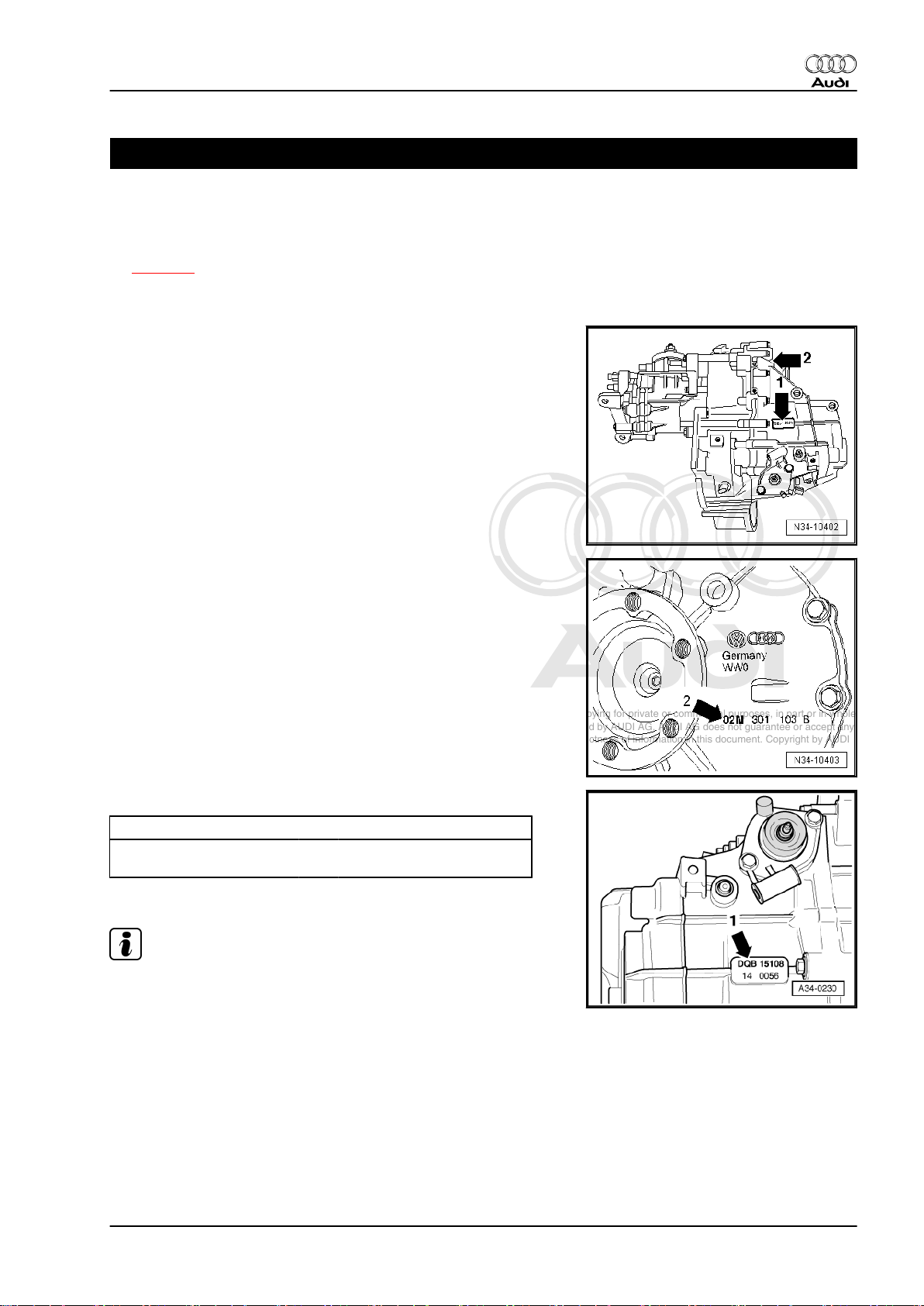
Location on gearbox
♦ Code letters and date of manufacture of gearbox -arrow 1-
♦ Manual gearbox 02M/O2Y, four-wheel drive -arrow 2-
Audi TT 1999 ➤
Manual gearbox 02M, four-wheel drive -arrow 2-
Code letters and date of manufacture of gearbox -arrow 1-
Example: DQB 15 10 8
Additional data are production-related.
Note
Code letters Day Month Year “1998” of
manufacture
The code letters of the gearbox are also given on the vehicle data
stickers.
1. Gearbox identification 1
Page 8
Protected by copyright. Copying for private or commercial purposes, in part or in whole, is not
permitted unless authorised by AUDI AG. AUDI AG does not guarantee or accept any liability
with respect to the correctness of information in this document. Copyright by AUDI AG.
Audi TT 1999 ➤
5/6-speed manual gearbox 02M/02Y, four-wheel drive - Edition 12.2004
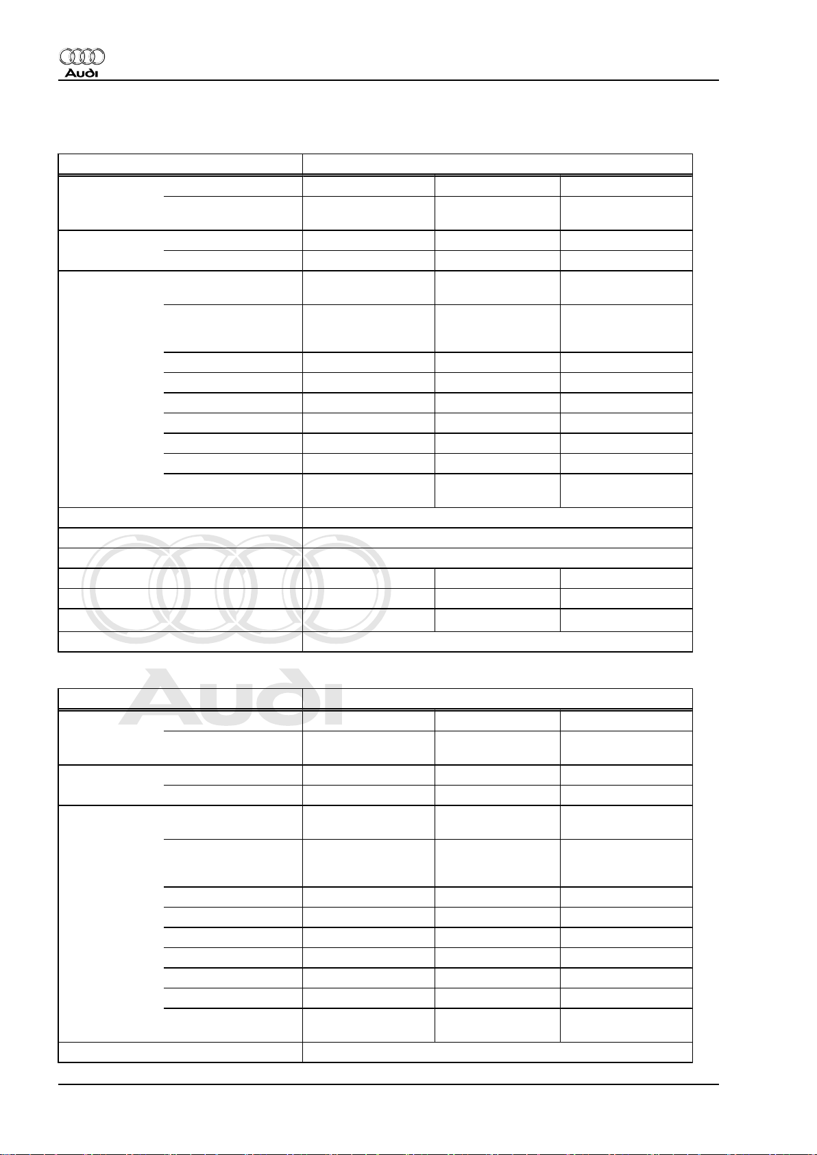
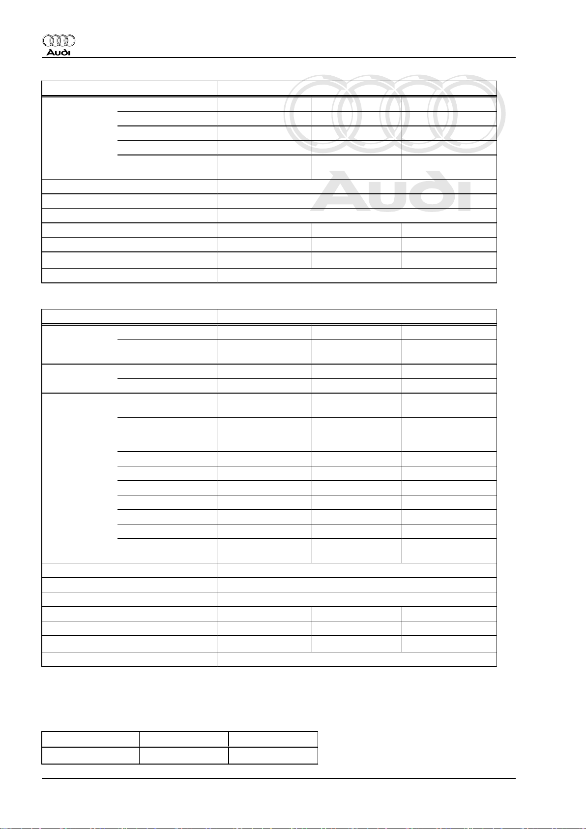
2 Code letters, allocation, transmission ratios, capacities
Manual gearbox 5/6-speed 02M, four-wheel drive
Gearbox Code letters DQB DXW EFY
Allocation Model Audi TT 1999 ▸ Audi TT 1999 ▸ Audi TT 1999 ▸
Ratios Final drive I
Z2 : Z
1
Capacity 2.6 litres
Specification ⇒ Parts catalogue
Clutch actuation Hydraulic
Clutch plate ∅ 240 mm 240 mm 240 mm
Drive shaft flange ∅ 108 mm 108 mm 108 mm
Overall ratio i
Allocation: rear final drive Designation 02D ⇒ Parts catalogue
Manufac‐
tured
from
to
09.00
02.01
09.0
01.01
09.00
02.01
Engine 1.8 ltr. - 165 kW 1.8 ltr. - 132 kW 1.8 ltr. - 132 kW
63 : 15 = 4.200 63 : 15 = 4.200 63 : 15 = 4.200
for 1st to 4th gear
Final drive II
63 : 19 = 3.316 63 : 19 = 3.316 63 : 19 = 3.316
for 5th/6th gear and
reverse gear
1st gear 41 : 12 = 3.417 42 : 11 = 3.818 41 : 12 = 3.417
2nd gear 40 : 19 = 2.105 40 : 19 = 2.105 40 : 19 = 2.105
3rd gear 40 : 28 = 1.429 39 : 29 = 1.345 40 : 27 = 1.481
4th gear 37 : 34 = 1.088 35 : 36 = 0.972 38 : 33 = 1.152
5th gear 34 : 31 = 1.097 32 : 33 = 0.970 35 : 30 = 1.167
6th gear 31 : 34 = 0.912 – 32 : 33 = 0.970
Reverse gear 30 : 12 x 23 : 14 =
4.108
in top gear 3.023 3.215 3.215
ov.
31 : 11 x 23 : 14 =
4.630
30 : 12 x 23 : 14 =
4.108
Manual gearbox 5/6-speed 02M, four-wheel drive
Gearbox Code letters FHA FHB FHC
Allocation Model Audi TT 1999 ▸ Audi TT 1999 ▸ Audi TT 1999 ▸
Ratios Final drive I
Manufac‐
tured
from
to
02.01
04.02
08.01
04.02
02.01
04.02
Engine 1.8 ltr. - 132 kW 1.8 ltr. - 165 kW 1.8 ltr. - 132 kW
63 : 15 = 4.200 63 : 15 = 4.200 63 : 15 = 4.200
for 1st to 4th gear
Z2 : Z
1
Final drive II
63 : 19 = 3.316 63 : 19 = 3.316 63 : 19 = 3.316
for 5th/6th gear and
reverse gear
1st gear 41 : 12 = 3.417 41 : 12 = 3.417 42 : 11 = 3.818
2nd gear 40 : 19 = 2.105 40 : 19 = 2.105 40 : 19 = 2.105
3rd gear 40 : 27 = 1.481 40 : 28 = 1.429 39 : 29 = 1.345
4th gear 38 : 33 = 1.152 37 : 34 = 1.088 35 : 36 = 0.972
5th gear 35 : 30 = 1.167 34 : 31 = 1.097 32 : 33 = 0.970
6th gear 32 : 33 = 0.970 31 : 34 = 0.912 –
Reverse gear 30 : 12 x 23 : 14 =
4.108
30 : 12 x 23 : 14 =
4.108
31 : 11 x 23 : 14 =
4.630
Capacity 2.6 litres
2 Rep. Gr.00 - Technical data
Page 9
Protected by copyright. Copying for private or commercial purposes, in part or in whole, is not
permitted unless authorised by AUDI AG. AUDI AG does not guarantee or accept any liability
with respect to the correctness of information in this document. Copyright by AUDI AG.
Audi TT 1999 ➤
5/6-speed manual gearbox 02M/02Y, four-wheel drive - Edition 12.2004
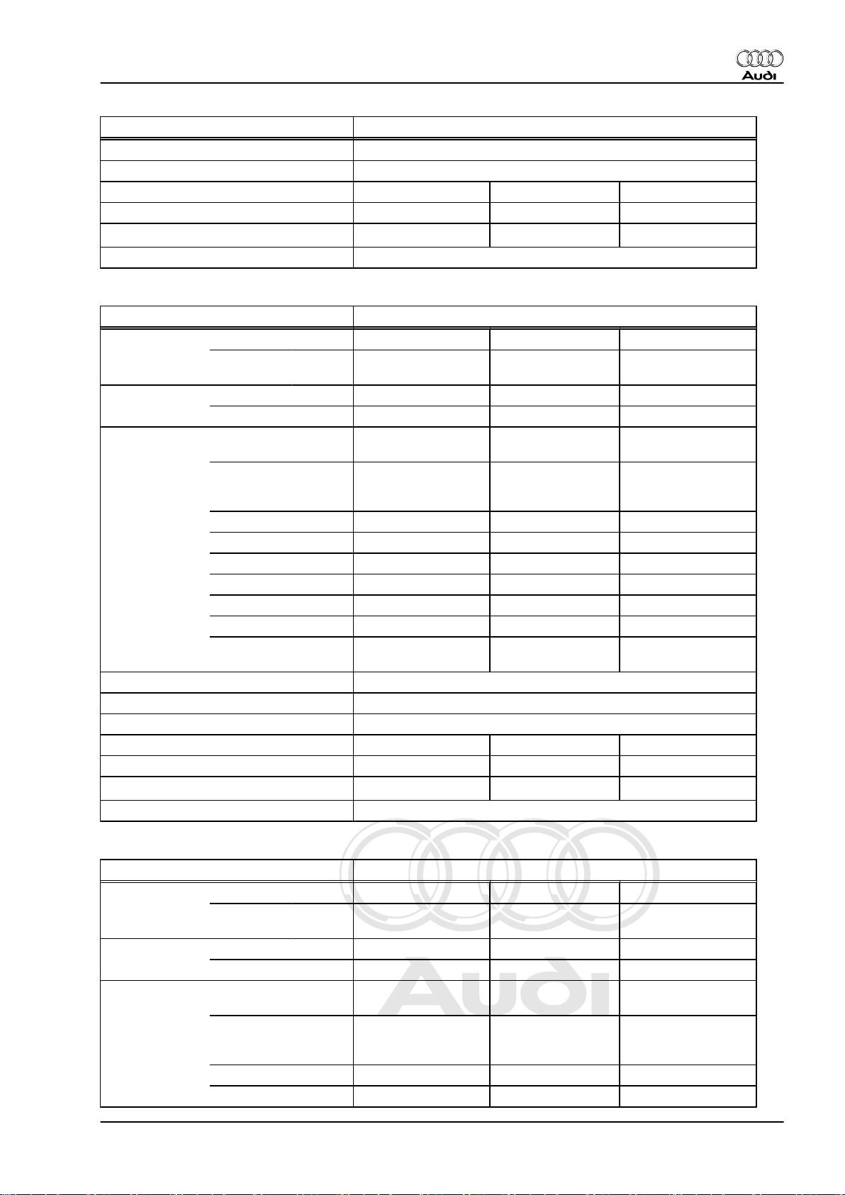
Manual gearbox 5/6-speed 02M, four-wheel drive
Specification ⇒ Parts catalogue
Clutch actuation Hydraulic
Clutch plate ∅ 240 mm 240 mm 240 mm
Drive shaft flange ∅ 108 mm 108 mm 108 mm
Overall ratio i
in top gear 3.215 3.023 3.215
ov.
Allocation: rear final drive Designation 02D ⇒ Parts catalogue
Manual gearbox 5/6-speed 02Y, four-wheel drive
Gearbox Code letters FMN FMR FMT
Manufac‐
tured
from
to
09.02
04.03
05.02
08.02
05.02
08.02
Allocation Model Audi TT 1999 ▸ Audi TT 1999 ▸ Audi TT 1999 ▸
Ratios Final drive I
Engine 1.8 ltr. -165 kW 1.8 ltr. - 132 kW 1.8 ltr. - 132 kW
72 : 17 = 4.235 72 : 17 = 4.235 72 : 17 = 4.235
for 1st to 4th gear
Z2 : Z
1
Final drive II
72 : 22 = 3.273 72 : 22 = 3.273 72 : 22 = 3.273
for 5th/6th gear and
reverse gear
1st gear 47 : 14 = 3.357 49 : 13 = 3.769 47 : 14 = 3.357
2nd gear 48 : 23 = 2.087 48 : 23 = 2.087 48 : 23 = 2.087
3rd gear 47 : 32 = 1.469 45 : 34 = 1.324 47 : 32 = 1.469
4th gear 45 : 41 = 1.098 42 : 43 = 0.977 46 : 40 = 1.150
5th gear 41 : 37 = 1.108 39 : 40 = 0.975 43 : 36 = 1.194
6th gear 38 : 41 = 0.927 – 39 : 40 = 0.975
Reverse gear 23 : 14 x 34 : 14 =
3.990
23 : 14 x 36 : 13 =
4.549
23 : 14 x 34 : 14 =
3.990
Capacity 2.6 litres
Specification ⇒ Parts catalogue
Clutch actuation Hydraulic
Clutch plate ∅ 240 mm 240 mm 240 mm
Drive shaft flange ∅ 108 mm 108 mm 108 mm
Overall ratio i
in top gear 3.033 3.191 3.191
ov.
Allocation: rear final drive Designation 02D ⇒ Parts catalogue
Manual gearbox 5/6-speed 02Y, four-wheel drive
Gearbox Code letters FZL FZP GQT
Manufac‐
tured
from
to
04.03 04.03 01.04
Allocation Model Audi TT 1999 ▸ Audi TT 1999 ▸ Audi TT 1999 ▸
Ratios Final drive I
Engine 1.8 ltr. - 165 kW 1.8 ltr. - 132 kW 3.2 ltr. - 184 kW
72 : 17 = 4.235 72 : 17 = 4.235 72 : 17 = 4.235
for 1st to 4th gear
Z2 : Z
1
Final drive II
for 5th/6th gear and
reverse gear
72 : 22 = 3.273 72 : 22 = 3.273 72 : 22 = 3.273
1st gear 47 : 14 = 3.357 47 : 14 = 3.357 47 : 14 = 3.357
2nd gear 48 : 23 = 2.087 48 : 23 = 2.087 48 : 23 = 2.087
2. Code letters, allocation, transmission ratios, capacities 3
Page 10
Protected by copyright. Copying for private or commercial purposes, in part or in whole, is not
permitted unless authorised by AUDI AG. AUDI AG does not guarantee or accept any liability
with respect to the correctness of information in this document. Copyright by AUDI AG.
Audi TT 1999 ➤
5/6-speed manual gearbox 02M/02Y, four-wheel drive - Edition 12.2004
Manual gearbox 5/6-speed 02Y, four-wheel drive
3rd gear 47 : 32 = 1.469 47 : 32 = 1.469 47 : 32 = 1.469
4th gear 45 : 41 = 1.098 46 : 40 = 1.150 37 : 34 = 1.088
5th gear 41 : 37 = 1.108 43 : 36 = 1.194 41 : 37 = 1.108
6th gear 38 : 41 = 0.927 39 : 40 = 0.975 31 : 34 = 0.912
Reverse gear 23 : 14 x 34 : 14 =
3.990
23 : 14 x 34 : 14 =
3.990
23 : 14 x 34 : 14 =
3.990
Capacity 2.6 litres
Specification ⇒ Parts catalogue
Clutch actuation Hydraulic
Clutch plate ∅ 240 mm 240 mm 240 mm
Drive shaft flange ∅ 108 mm 108 mm 108 mm
Overall ratio i
in top gear 3.033 3.191 2.984
ov.
Allocation: rear final drive Designation 02D ⇒ Parts catalogue
Manual gearbox 5/6-speed 02Y, four-wheel drive
Gearbox Code letters GQV
Manufac‐
tured
from
to
01.04
Allocation Model Audi TT 1999 ▸
Ratios Final drive I
Z2 : Z
1
Engine 3.2 ltr. - 184 kW
for 1st to 4th gear
Final drive II
72 : 17 = 4.235
72 : 22 = 3.273
for 5th/6th gear and
reverse gear
1st gear 47 : 14 = 3.357
2nd gear 48 : 23 = 2.087
3rd gear 47 : 32 = 1.469
4th gear 37 : 34 = 1.088
5th gear 41 : 37 = 1.108
6th gear 31 : 34 = 0.912
Reverse gear 23 : 14 x 34 : 14 =
3.990
Capacity 2.6 litres
Specification ⇒ Parts catalogue
Clutch actuation Hydraulic
Clutch plate ∅ 240 mm
Drive shaft flange ∅ 108 mm
Overall ratio i
in top gear 2.984
ov.
Allocation: rear final drive Designation 02D ⇒ Parts catalogue
2.1 Calculating ratio “i”
Example:
6th gear Final drive
Drive gear ZG1 = 34 ZA1 = 19
4 Rep. Gr.00 - Technical data
Page 11

Protected by copyright. Copying for private or commercial purposes, in part or in whole, is not
permitted unless authorised by AUDI AG. AUDI AG does not guarantee or accept any liability
with respect to the correctness of information in this document. Copyright by AUDI AG.
Audi TT 1999 ➤
5/6-speed manual gearbox 02M/02Y, four-wheel drive - Edition 12.2004
6th gear Final drive
Driven gear ZG2 = 31 ZA2 = 63
i = Z2 : Z1 (Z1 = number of teeth on drive gear, Z2 = number of
teeth on driven gear)
iG = gear ratio = ZG2 : ZG1 = 31 : 34 = 0.912
iA = axle ratio = ZA2 : ZA1 = 63 : 19 = 3.316
iov = overall ratio = iG x iA = 0.912 x 3.316 = 3.023
2. Code letters, allocation, transmission ratios, capacities 5
Page 12
Protected by copyright. Copying for private or commercial purposes, in part or in whole, is not
permitted unless authorised by AUDI AG. AUDI AG does not guarantee or accept any liability
with respect to the correctness of information in this document. Copyright by AUDI AG.
Audi TT 1999 ➤
5/6-speed manual gearbox 02M/02Y, four-wheel drive - Edition 12.2004
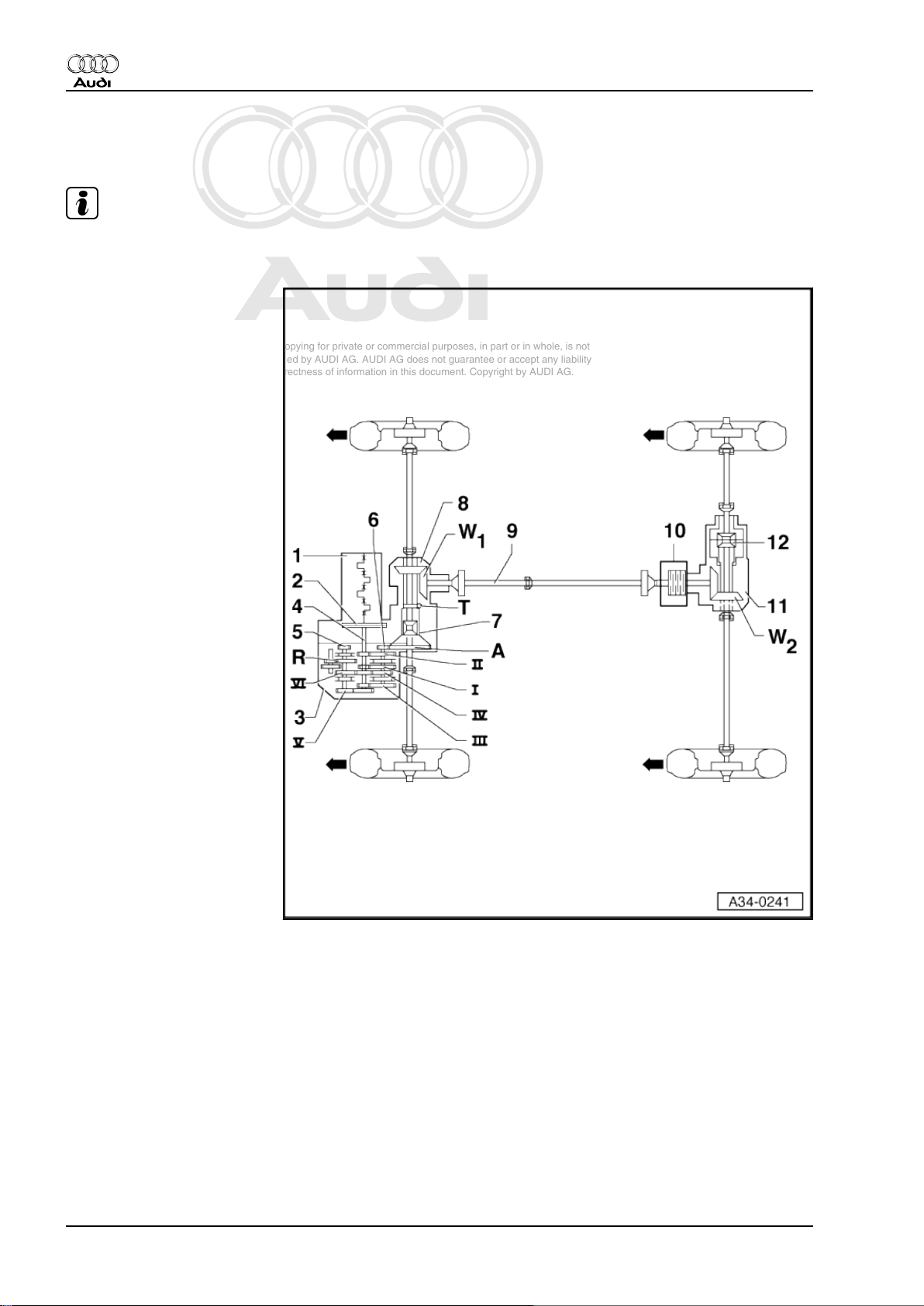
3 Transmission layout
Note
Arrows point in direction of travel
1 - Engine
2 - Clutch
3 - Manual gearbox
4 - Input shaft
5 - Output shaft for 5th/6th/re‐
verse gear (pinion shaft II)
6 - Output shaft for 1st-4th gear
(pinion shaft I)
7 - Differential
8 - Bevel box
9 - Propshaft
10 - Haldex coupling
11 - Rear final drive
12 - Differential
I - 1st gear
II - 2nd gear
III - 3rd gear
IV - 4th gear
V - 5th gear
VI - 6th gear
R - Reverse gear
A - Final drive
T - Speedometer drive
W1 - Front bevel gears
W2 - Rear bevel gears
6 Rep. Gr.00 - Technical data
Page 13
Protected by copyright. Copying for private or commercial purposes, in part or in whole, is not
permitted unless authorised by AUDI AG. AUDI AG does not guarantee or accept any liability
with respect to the correctness of information in this document. Copyright by AUDI AG.
5/6-speed manual gearbox 02M/02Y, four-wheel drive - Edition 12.2004
4 General repair instructions
Proper tools and the maximum possible care and cleanliness are
essential for satisfactory gearbox repairs. The usual basic safety
precautions also naturally apply when carrying out repair work.
A number of generally applicable instructions for the various re‐
pair procedures - which were previously repeated at numerous
places in the Workshop Manual - are summarised here. They ap‐
ply to the work described in this Manual.
4.1 Contact corrosion
♦ The housing of the manual gearbox in the Audi TT is made of
a magnesium alloy.
♦ Bolts and other components which are in direct contact with
the gearbox casing are surface treated for compatibility with
magnesium.
♦ If the incorrect components are used (bolts, nuts, washers
etc.), this will cause contact corrosion. The gearbox housing
will be damaged.
♦ If you are not sure whether used parts can be re-installed, al‐
ways fit new parts.
Audi TT 1999 ➤
Caution
♦ Only use Genuine Audi parts.
♦ Damage resulting from contact corrosion is not covered
by the warranty.
4.2 Special tools
For a complete list of special tools used in this Workshop Manual
⇒ Special tools, Workshop equipment .
4.3 Components
Gearbox
♦ When installing, ensure that the dowel sleeves between the
engine and gearbox are correctly located.
♦ When assembling mounting brackets as well as other waxed
components, the contact surfaces must be cleaned. The con‐
tact surfaces must be free of wax and grease.
♦ When installing a new gearbox or bevel box fill with gear oil.
♦ Capacities and specifications ⇒ page 2 .
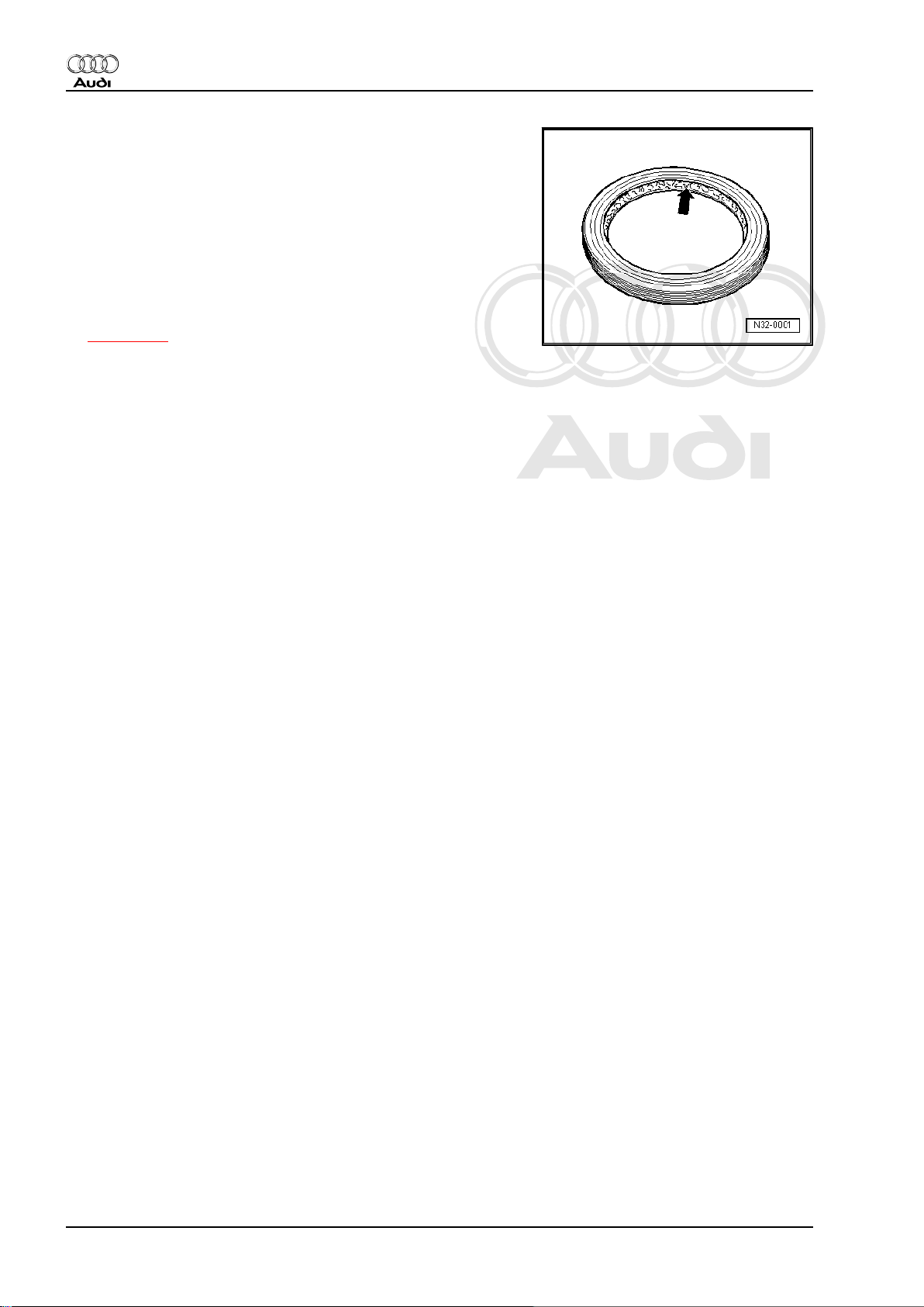
O-rings, oil seals, gaskets
♦ Always install new O-rings, oil seals and gaskets.
♦ After removing gaskets and seals, always inspect the contact
surface on the housing or shaft for burrs resulting from removal
or for other signs of damage.
♦ Clean joints thoroughly and apply sealant -AMV 188 200 03- .
♦ Apply sealant evenly and not too thickly.
Before installing:
4. General repair instructions 7
Page 14
Protected by copyright. Copying for private or commercial purposes, in part or in whole, is not
permitted unless authorised by AUDI AG. AUDI AG does not guarantee or accept any liability
with respect to the correctness of information in this document. Copyright by AUDI AG.
Audi TT 1999 ➤
5/6-speed manual gearbox 02M/02Y, four-wheel drive - Edition 12.2004
♦ Lightly oil the outer circumference of oil seals and fill the space
between the sealing lips -arrow- about half full with grease -G
052 128 A1- .
♦ The open side of the oil seals faces toward the side with fluid
filling.
♦ When installing a new oil seal, position the seal in the housing
so that sealing lip does not contact the shaft in the same place
as the old seal (make use of insertion depth tolerances).
After installation:
♦ Check gear oil level in manual gearbox with bevel box
⇒ page 115 .
8 Rep. Gr.00 - Technical data
Page 15
Protected by copyright. Copying for private or commercial purposes, in part or in whole, is not
permitted unless authorised by AUDI AG. AUDI AG does not guarantee or accept any liability
with respect to the correctness of information in this document. Copyright by AUDI AG.
5/6-speed manual gearbox 02M/02Y, four-wheel drive - Edition 12.2004
Locking elements
♦ Do not over-stretch circlips.
♦ Always renew circlips which have been damaged or over-
stretched.
♦ Circlips must be properly seated in the base of the groove.
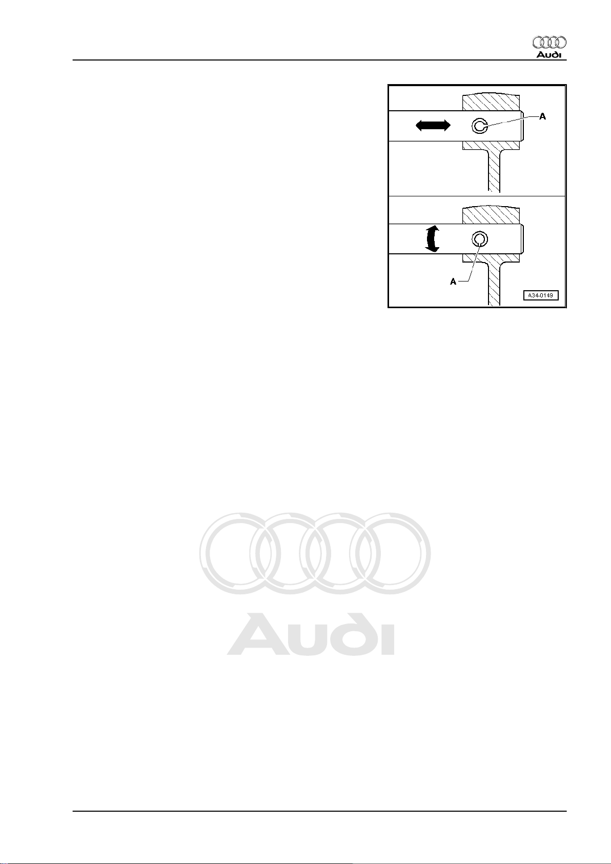
♦ Renew spring pins. Position: the slit -A- should be in line with
the line of force -arrow-.
Nuts, bolts
♦ Nuts and bolts for securing covers and housings must be
slackened and tightened in diagonal sequence.
♦ Parts which are particularly sensitive (e.g. clutch pressure
plates) must be kept straight. Slacken and tighten them in
stages and in diagonal sequence.
♦ The tightening torques stated apply to non-oiled nuts and
bolts.
♦ Always renew self-locking bolts and nuts.
♦ For all threaded connections, ensure that (where applicable)
the contact surfaces and the nuts and bolts are not coated with
wax until after assembly is completed.
Bearings
♦ Install new tapered roller bearings as supplied; do not lubricate
additionally with oil.
♦ Lubricate all bearings (except tapered roller bearings) with
gear oil before installing in gearbox.
♦ Always renew the tapered roller bearings on one shaft togeth‐
er as a set and use new bearings from a single manufacturer.
♦ Heat inner races of tapered roller bearings to approx. 100°C
before installing. Press in onto stop when installing so there is
no axial clearance.
♦ Do not interchange the outer or inner races of bearings of the
same size (the bearings are paired).
♦ Install needle bearings so the lettering (side with thicker metal)
faces towards the installing tool.
Shims
♦ Measure shims at several points with a micrometer. Tolerance
variations make it possible to obtain the exact shim thickness
required.
♦ Check for burrs and damage.
♦ Install only shims which are in perfect condition.
Synchroniser rings
♦ Do not interchange. When reusing synchroniser rings, always
fit to the same gear wheel.
♦ Check for wear; renew if necessary.
♦ Lubricate with gear oil before installing.
Gear wheels
♦ Before installing, clean and heat on a hotplate to approx. 100°
C.
♦ The temperature can be checked with Temperature tester -
V.A.G 1558- .
Audi TT 1999 ➤
4. General repair instructions 9
Page 16

Protected by copyright. Copying for private or commercial purposes, in part or in whole, is not
permitted unless authorised by AUDI AG. AUDI AG does not guarantee or accept any liability
with respect to the correctness of information in this document. Copyright by AUDI AG.
Audi TT 1999 ➤
5/6-speed manual gearbox 02M/02Y, four-wheel drive - Edition 12.2004
Selector gears
♦ After installing, check 1st to 6th speed selector gears for min‐
imal axial play and freedom of movement.
Clutch actuation
♦ Ensure that the pressure plate is kept straight: loosen and
tighten bolts in a diagonal sequence and in several gradual
stages.
♦ If the clutch has burnt out, thoroughly clean the bell housing,
flywheel and parts of the engine facing the gearbox in order to
prevent odours.
10 Rep. Gr.00 - Technical data
Page 17
Protected by copyright. Copying for private or commercial purposes, in part or in whole, is not
permitted unless authorised by AUDI AG. AUDI AG does not guarantee or accept any liability
with respect to the correctness of information in this document. Copyright by AUDI AG.
5/6-speed manual gearbox 02M/02Y, four-wheel drive - Edition 12.2004
30 – Clutch
1 Servicing clutch mechanism
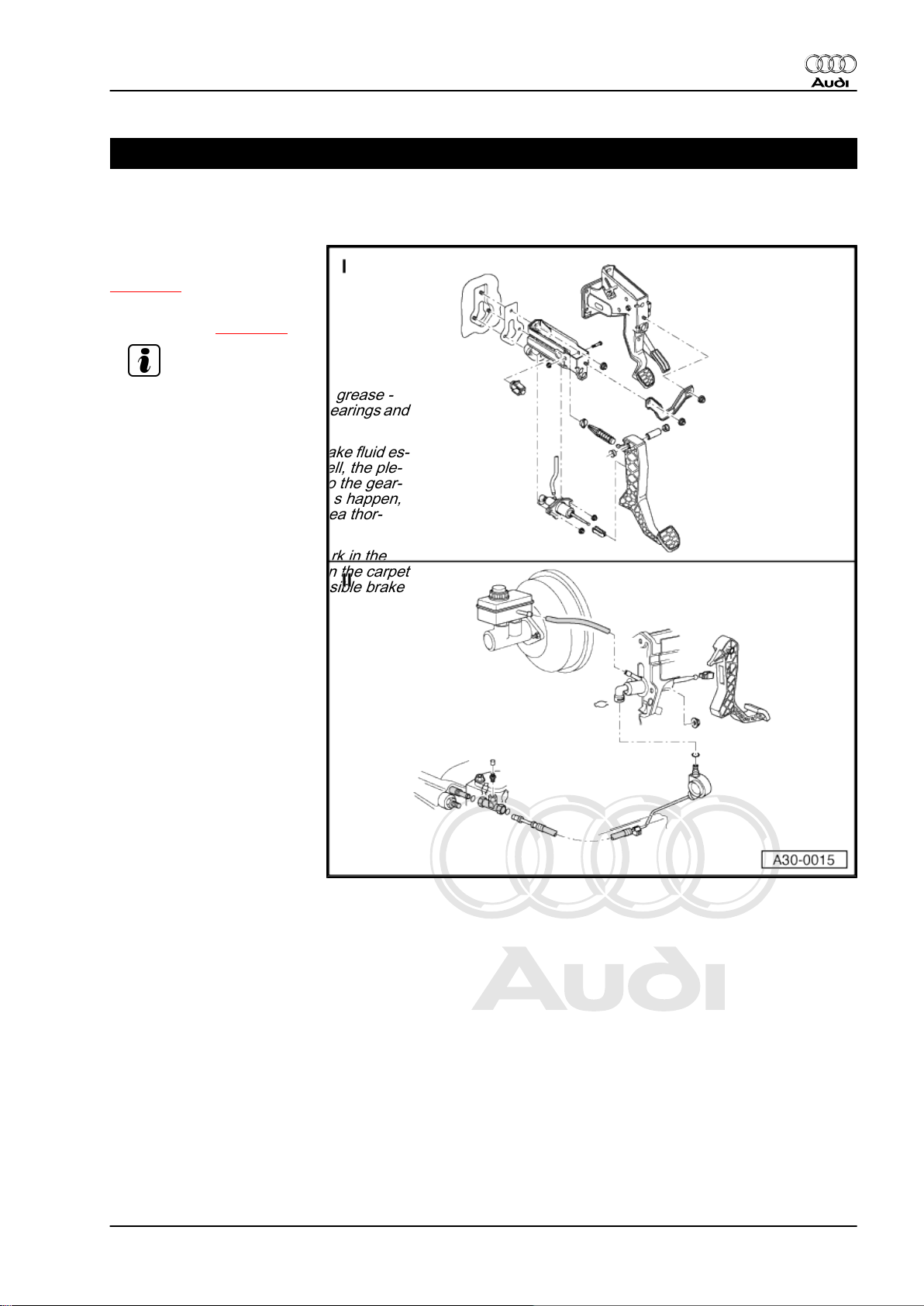
I - Pedal cluster - exploded
view of components
⇒ page 12
II - Hydraulics - exploded view
of components ⇒ page 16
Note
♦
Apply polycarbamide grease -
G 052 142 A2- to all bearings and
contact surfaces.
♦
Make sure that no brake fluid es‐
capes into the footwell, the ple‐
num chamber or onto the gear‐
box below. If this does happen,
clean the affected area thor‐
oughly.
♦
When performing work in the
footwell, put cloths on the carpet
to protect it from possible brake
fluid spills.
Audi TT 1999 ➤
1. Servicing clutch mechanism 11
Page 18
Protected by copyright. Copying for private or commercial purposes, in part or in whole, is not
permitted unless authorised by AUDI AG. AUDI AG does not guarantee or accept any liability
with respect to the correctness of information in this document. Copyright by AUDI AG.
Audi TT 1999 ➤
5/6-speed manual gearbox 02M/02Y, four-wheel drive - Edition 12.2004
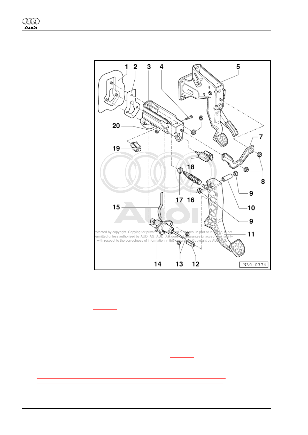
1.1 Pedal cluster - exploded view of components
1 - Cross panel
❑ With mounting for
mounting bracket and
master cylinder
2 - Gasket
❑ Always renew
3 - Mounting bracket
❑ For mounting clutch
pedal
4 - Bolt
5 - Mounting bracket
❑ For mounting accelera‐
tor pedal and brake ped‐
al
6 - Hexagon nut, 25 Nm
❑ Self-locking
❑ Renew
7 - Connecting plate
8 - Hexagon nut, 25 Nm
❑ Self-locking
❑ Renew
9 - Mounting bush
10 - Pivot pin
11 - Clutch pedal
❑ Removing and installing
⇒ page 15
12 - Retaining clip
❑ Removing and installing
⇒ Item 4 (page 16)
13 - Hexagon nut, 25 Nm
❑ Self-locking
❑ Renew
14 - Clutch master cylinder
❑ Removing and installing ⇒ page 18
15 - Supply hose
16 - Over-centre spring
❑ Removing and installing ⇒ page 14
17 - Mounting for over-centre spring
❑ Install in mounting bracket
❑ When renewing: remove and install clutch master cylinder ⇒ page 18
18 - Clutch pedal switch -F36-
❑ Removing and installing
⇒ “1.2 Removing and installing clutch pedal switch F36 (square housing)”, page 13 or
⇒ “1.3 Removing and installing clutch pedal switch F36 (round housing)”, page 13
19 - Stop for clutch pedal
❑ Installation position ⇒ page 20
12 Rep. Gr.30 - Clutch
Page 19
Protected by copyright. Copying for private or commercial purposes, in part or in whole, is not
permitted unless authorised by AUDI AG. AUDI AG does not guarantee or accept any liability
with respect to the correctness of information in this document. Copyright by AUDI AG.
5/6-speed manual gearbox 02M/02Y, four-wheel drive - Edition 12.2004
20 - Hexagon nut, 25 Nm
❑ Self-locking
❑ Renew
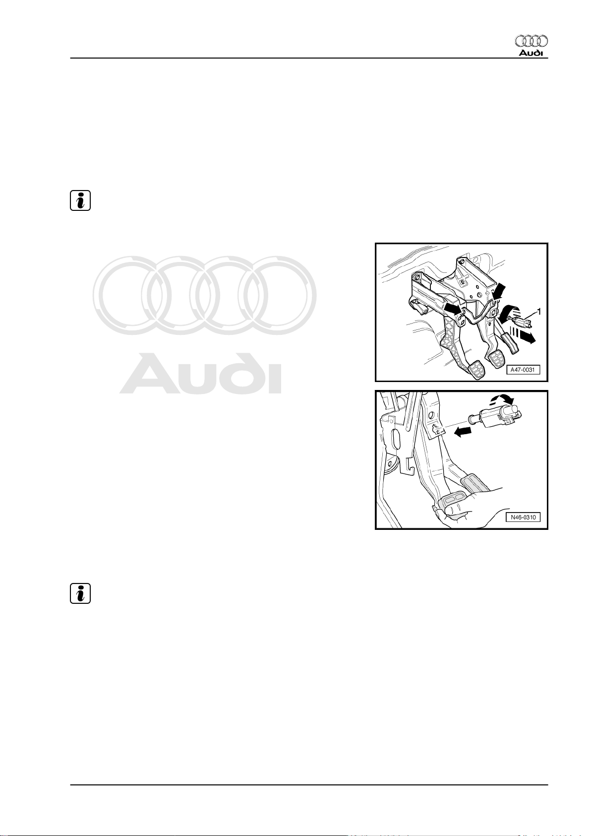
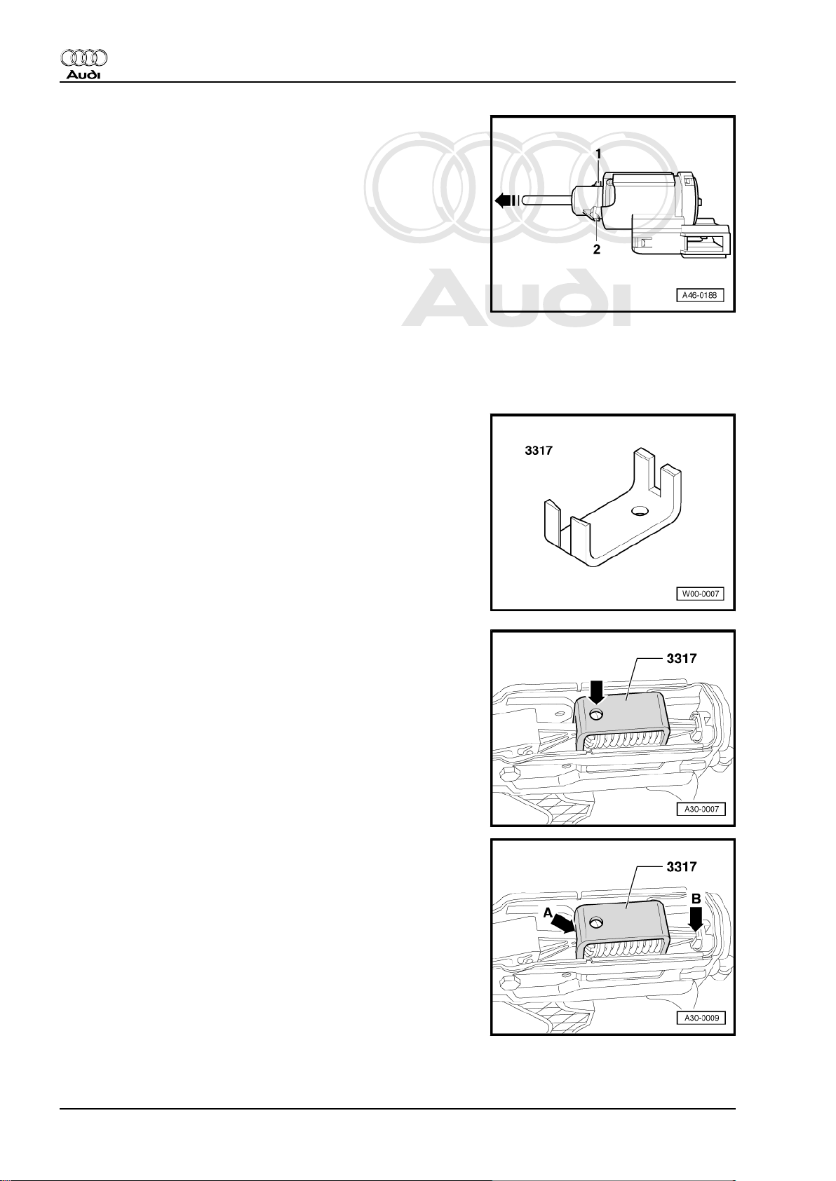
1.2 Removing and installing clutch pedal switch -F36- (square housing)
Note
Switch may only be fitted once so as to ensure a firm fit.
Removing
– Remove storage compartment on driver's side ⇒ General
body repairs, interior; Rep. Gr. 68 .
– Unplug electrical connector from clutch pedal switch.
– Remove clutch pedal switch -1- by turning 90° anti-clockwise.
Audi TT 1999 ➤
Installing
Installation is carried out in reverse sequence; note the following:
– Pull operating rod of clutch pedal switch out onto stop.
– Push clutch pedal down by hand.
– Insert switch in mounting hole and secure by turning clockwise
through 90° -arrows-.
– Release clutch pedal
– Install storage compartment on driver's side ⇒ General body
repairs, interior; Rep. Gr. 68 .
1.3 Removing and installing clutch pedal switch -F36- (round housing)
Note
Clutch pedal switch may only be fitted once so as to ensure a firm
fit.
Removing
– Remove storage compartment on driver's side ⇒ General
body repairs, interior; Rep. Gr. 68 .
– Unplug electrical connector from clutch pedal switch.
– Remove clutch pedal switch by turning in anti-clockwise di‐
rection through 45°.
1. Servicing clutch mechanism 13
Page 20
Protected by copyright. Copying for private or commercial purposes, in part or in whole, is not
permitted unless authorised by AUDI AG. AUDI AG does not guarantee or accept any liability
with respect to the correctness of information in this document. Copyright by AUDI AG.
Audi TT 1999 ➤
5/6-speed manual gearbox 02M/02Y, four-wheel drive - Edition 12.2004
Installing
Installation is carried out in reverse sequence; note the following:
– Pull out operating rod -arrow- all the way before installing
clutch pedal switch.
• The clutch pedal should be in the normal position (i.e. not
pressed down).
– Guide clutch pedal switch through mounting hole, press oper‐
ating rod against clutch pedal and attach switch by turning 45°
clockwise.
– Install storage compartment on driver's side ⇒ General body
repairs, interior; Rep. Gr. 68 .
1.4 Removing and installing over-centre
spring
Special tools and workshop equipment required
♦ Assembly clip -3317-
Removing
– Remove storage compartment on driver's side ⇒ General
body repairs, interior; Rep. Gr. 68 .
– Press down clutch pedal to compress the over-centre spring
and fit assembly clip -3317- from the top onto over-centre
spring.
• The drilling -arrow- faces towards clutch pedal.
– Return clutch pedal to normal position and remove over-centre
spring together with assembly clip -3317- .
Installing
– Pull clutch pedal into passenger compartment.
– Insert over-centre spring into rear mounting -arrow B- first,
then operate clutch pedal until the assembly clip -3317- seats
against the mounting lug -arrow A- of the clutch pedal.
–
– Return clutch pedal to normal position and remove assembly
clip -3317- .
14 Rep. Gr.30 - Clutch
Page 21
Protected by copyright. Copying for private or commercial purposes, in part or in whole, is not
permitted unless authorised by AUDI AG. AUDI AG does not guarantee or accept any liability
with respect to the correctness of information in this document. Copyright by AUDI AG.
5/6-speed manual gearbox 02M/02Y, four-wheel drive - Edition 12.2004
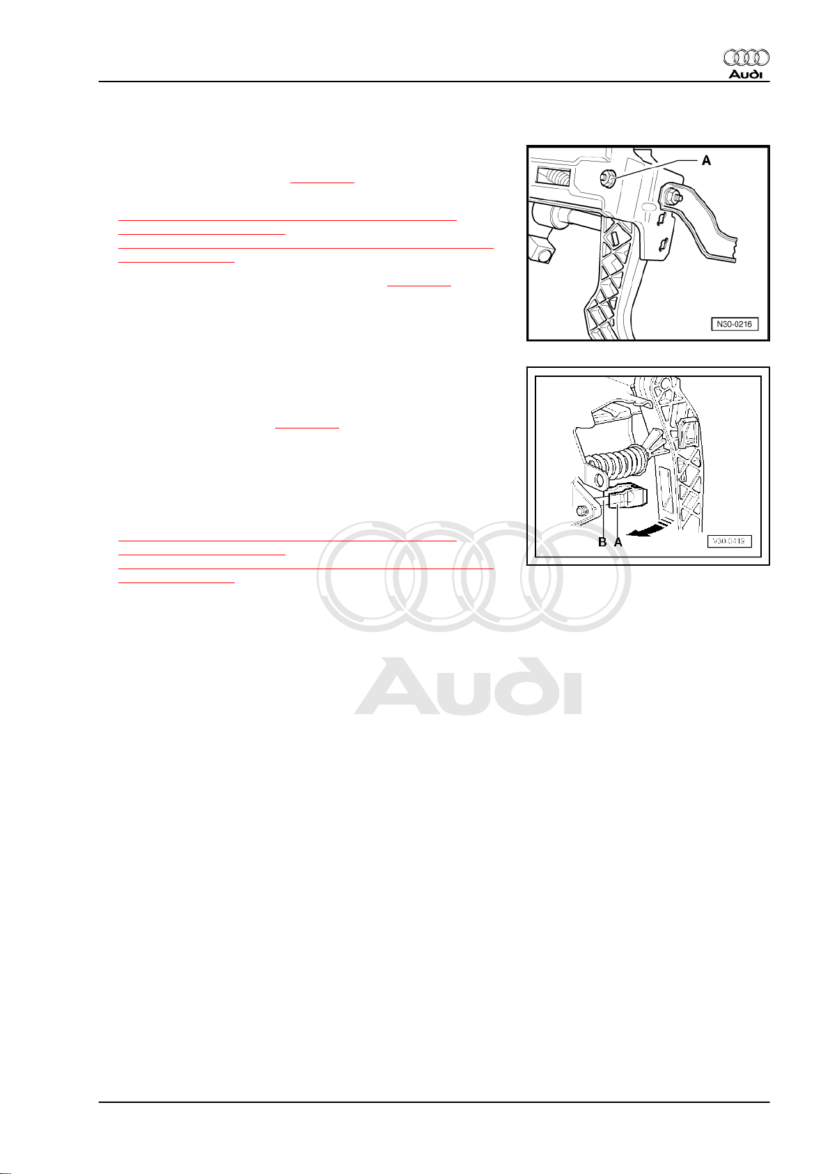
1.5 Removing and installing clutch pedal
Removing
– Remove over-centre spring ⇒ page 14 .
– Remove clutch pedal switch
⇒ “1.2 Removing and installing clutch pedal switch F36
(square housing)”, page 13 or
⇒ “1.3 Removing and installing clutch pedal switch F36 (round
housing)”, page 13 .
– Separate clutch pedal from master cylinder ⇒ page 18 and
push operating rod towards bulkhead onto stop.
– Remove nut -A-.
– Pull bolt out until the clutch pedal can be removed.
Installing
Installation is carried out in reverse sequence; note the following:
– Install over-centre spring ⇒ page 14 .
• The retaining clip -A- must be fitted on the master cylinder op‐
erating rod -B-.
– Press clutch pedal in direction of -arrow- to engage. Ensure
that pedal is correctly located.
– Install clutch pedal switch
⇒ “1.2 Removing and installing clutch pedal switch F36
(square housing)”, page 13 or
⇒ “1.3 Removing and installing clutch pedal switch F36 (round
housing)”, page 13 .
Audi TT 1999 ➤
1. Servicing clutch mechanism 15
Page 22
Protected by copyright. Copying for private or commercial purposes, in part or in whole, is not
permitted unless authorised by AUDI AG. AUDI AG does not guarantee or accept any liability
with respect to the correctness of information in this document. Copyright by AUDI AG.
Audi TT 1999 ➤
5/6-speed manual gearbox 02M/02Y, four-wheel drive - Edition 12.2004
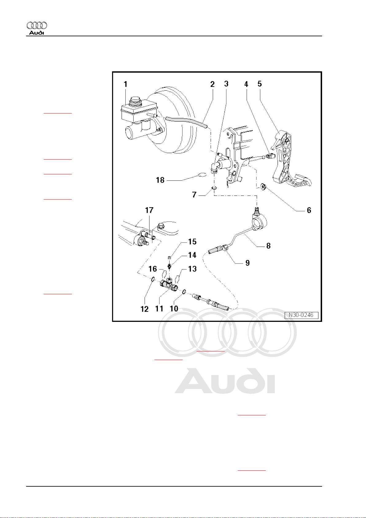
1.6 Hydraulics - exploded view of components
1 - Brake fluid reservoir
2 - Supply hose
3 - Clutch master cylinder
❑ Removing and installing
⇒ page 18
4 - Retaining clip
❑ Only renew when clutch
master cylinder has
been removed
❑ Lever off to remove
⇒ page 17
❑ Pressing on
⇒ page 17
5 - Clutch pedal
❑ Removing and installing
⇒ page 15
6 - Hexagon nut, 25 Nm
❑ 2 x
❑ Self-locking
❑ Renew
7 - Seal/O-ring
❑ Renew; for correct ver‐
sion refer to ⇒ Parts
catalogue
❑ Whether a seal or an O-
ring is used depends on
the type of connection
⇒ page 17 .
❑ Lubricate with brake flu‐
id before installing
❑ Push onto pipe connec‐
tion
8 - Pipe/hose assembly
❑ With frequency modulator
❑ Disconnecting from clutch master cylinder and installing ⇒ page 19
❑ Disconnecting from clutch slave cylinder ⇒ page 62
❑ For correct version refer to ⇒ Parts catalogue
9 - Retainer
❑ Attached to body
10 - Seal/O-ring
❑ Renew; for correct version refer to ⇒ Parts catalogue
❑ Whether a seal or an O-ring is used depends on the type of connection ⇒ page 17 .
❑ Lubricate with brake fluid before installing
❑ Push onto pipe connection
11 - Bleeder connection
12 - Seal/O-ring
❑ Renew; for correct version refer to ⇒ Parts catalogue
❑ Whether a seal or an O-ring is used depends on the type of connection ⇒ page 17 .
❑ Lubricate with brake fluid before installing
16 Rep. Gr.30 - Clutch
Page 23
Protected by copyright. Copying for private or commercial purposes, in part or in whole, is not
permitted unless authorised by AUDI AG. AUDI AG does not guarantee or accept any liability
with respect to the correctness of information in this document. Copyright by AUDI AG.
5/6-speed manual gearbox 02M/02Y, four-wheel drive - Edition 12.2004
❑ Push onto pipe connection
13 - Clip
❑ To remove pipe, pull out clip as far as limit stop ⇒ page 19
14 - Bleeder valve
❑ Bleeding clutch system ⇒ page 21
15 - Dust cap
16 - Clip
❑ To remove pipe, pull out clip as far as limit stop ⇒ page 19
17 - Clutch slave cylinder (release bearing with hydraulic actuator)
❑ Can only be removed after removing gearbox
❑ Removing and installing ⇒ page 21
18 - Clip
❑ To remove pipe, pull out clip as far as limit stop ⇒ page 19
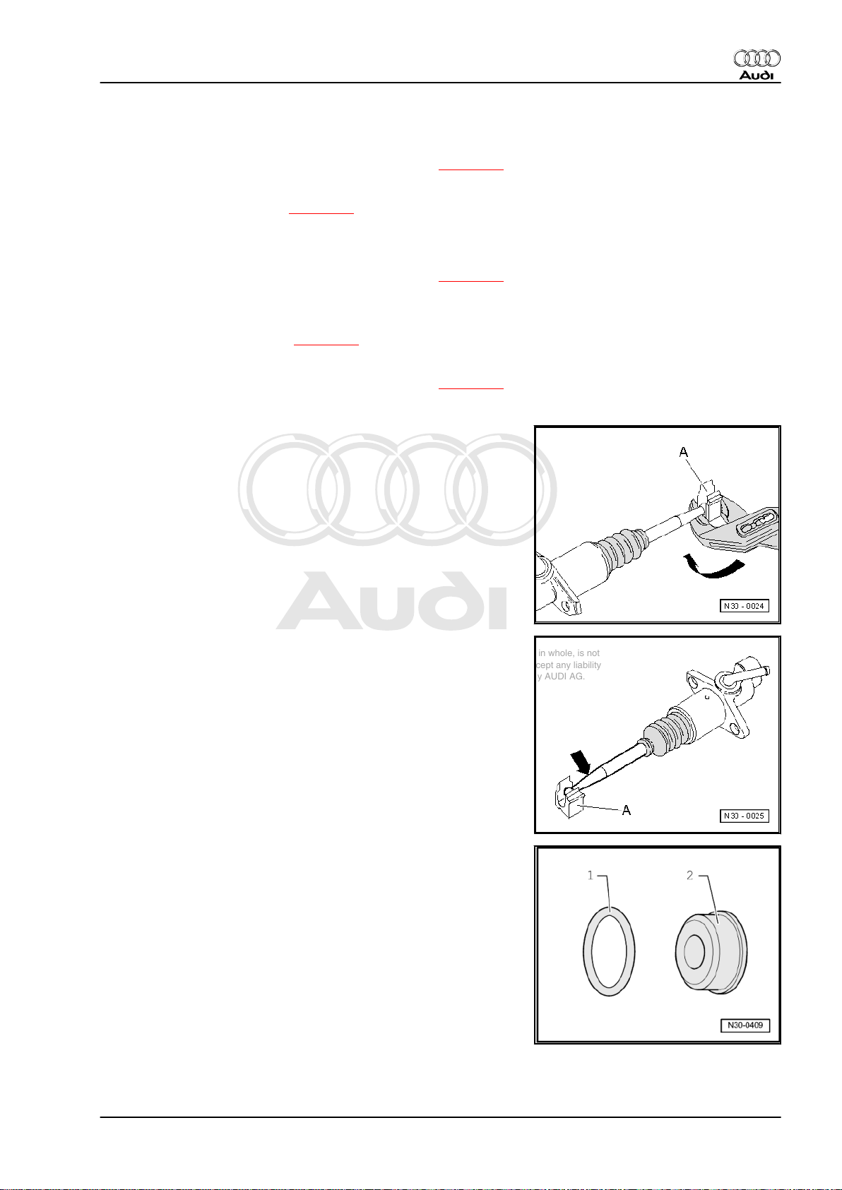
Levering off retaining clip
– Lever retaining clip -A- off in direction of -arrow- using pliers.
Audi TT 1999 ➤
Pressing master cylinder operating rod into retaining clip
– Press master cylinder operating rod into retaining clip -A-
-arrow-.
Seals/O-rings for pipe/hose assemblies
1 - For metal pipe/hose assemblies
2 - For synthetic pipe/hose assemblies
1. Servicing clutch mechanism 17
Page 24
Protected by copyright. Copying for private or commercial purposes, in part or in whole, is not
permitted unless authorised by AUDI AG. AUDI AG does not guarantee or accept any liability
with respect to the correctness of information in this document. Copyright by AUDI AG.
Audi TT 1999 ➤
5/6-speed manual gearbox 02M/02Y, four-wheel drive - Edition 12.2004
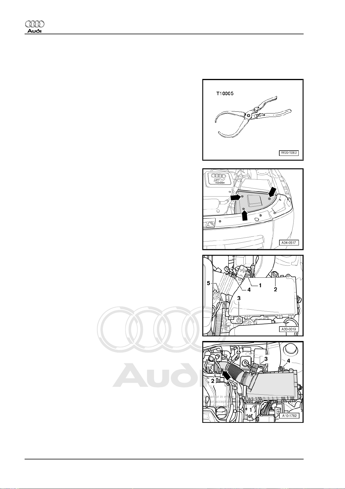
1.7 Removing and installing clutch master cylinder
Special tools and workshop equipment required
♦ Pliers -T10005-
Removing
– Remove cover panel (front left) -arrows-.
Vehicles with 4-cylinder engine:
– Detach air intake hose at throttle valve module -J338- (slacken
hose clip -4-).
– Unplug electrical connector for air mass meter -G70- -1-.
– If fitted, detach hose -5- from air cleaner housing.
– Remove bolts -2- and -3-.
– Take out air cleaner housing.
Vehicles with 6-cylinder engine:
– Detach air intake hose -2- at throttle valve module -J338- .
– Unplug electrical connector for air mass meter -G70- -3-.
– Remove bolts -1- and -4-.
– Move electrical wire -arrow- clear.
– Take out air cleaner housing.
18 Rep. Gr.30 - Clutch
Page 25
Protected by copyright. Copying for private or commercial purposes, in part or in whole, is not
permitted unless authorised by AUDI AG. AUDI AG does not guarantee or accept any liability
with respect to the correctness of information in this document. Copyright by AUDI AG.
5/6-speed manual gearbox 02M/02Y, four-wheel drive - Edition 12.2004
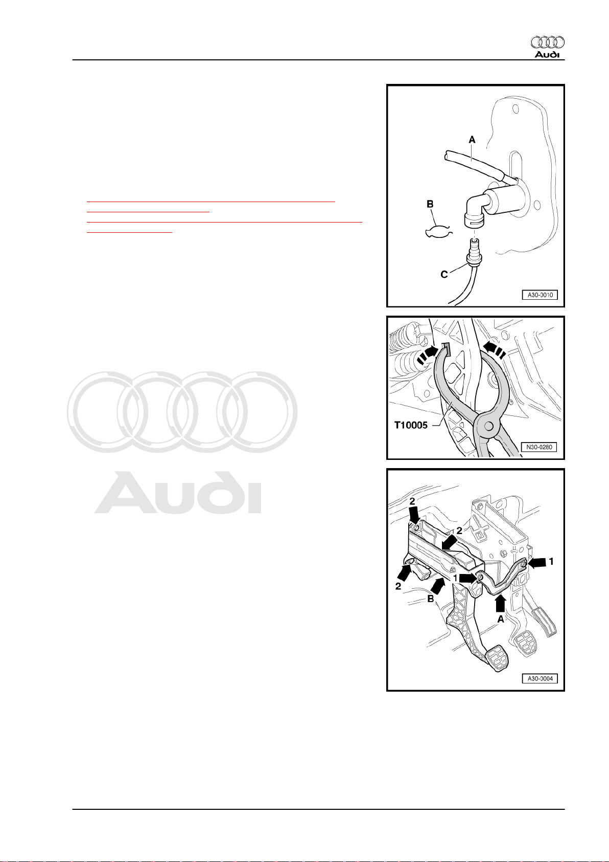
All models:
– Pull off supply hose -A- going to brake fluid reservoir and seal.
– Pull out clip -B- for pipe/hose assembly.
– Pull pipe/hose assembly -C- out from master cylinder and seal.
– Remove storage compartment on driver's side ⇒ General
body repairs, interior; Rep. Gr. 68 .
– Remove clutch pedal switch
⇒ “1.2 Removing and installing clutch pedal switch F36
(square housing)”, page 13 or
⇒ “1.3 Removing and installing clutch pedal switch F36 (round
housing)”, page 13 .
– Pull clutch pedal lightly towards the passenger compartment
to separate master cylinder operating rod from clutch pedal
and press both sides of retaining clip inwards -arrows- using
pliers -T10005- .
Audi TT 1999 ➤
– Remove connecting plate -A- -arrows 1-.
– Remove nuts -arrows 2- and take off mounting bracket -B-.
1. Servicing clutch mechanism 19
Page 26
Protected by copyright. Copying for private or commercial purposes, in part or in whole, is not
permitted unless authorised by AUDI AG. AUDI AG does not guarantee or accept any liability
with respect to the correctness of information in this document. Copyright by AUDI AG.
Audi TT 1999 ➤
5/6-speed manual gearbox 02M/02Y, four-wheel drive - Edition 12.2004
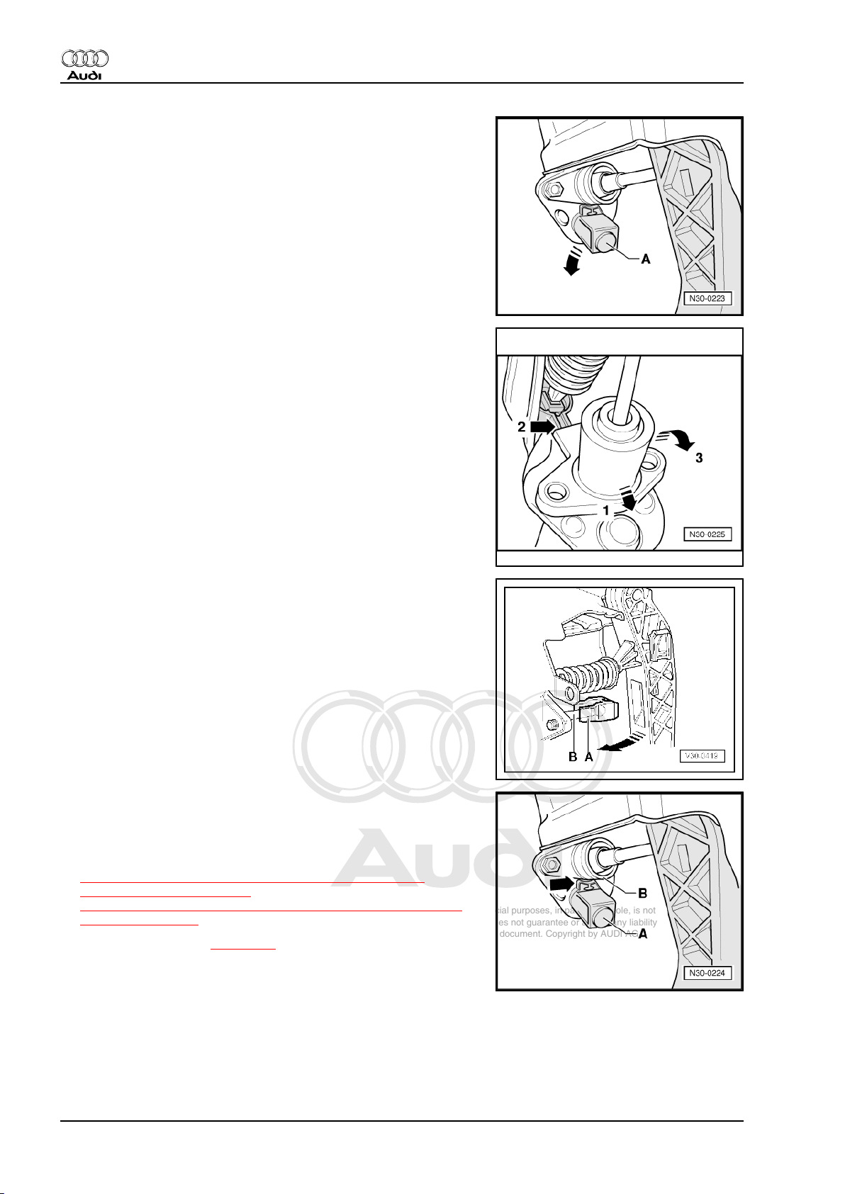
– Turn stop -A- for clutch pedal in direction of -arrow- and re‐
move.
– Then push master cylinder in the direction of -arrow 1- onto
stop.
• It must not be covered in upper area by over-centre spring
mounting -arrow 2-.
– Then swing master cylinder in direction of -arrow 3- out of
mounting bracket.
Installing
Installation is carried out in reverse sequence; note the following:
• The retaining clip -A- must be fitted on the master cylinder op‐
erating rod -B-.
– Press clutch pedal in direction of -arrow- to engage. Ensure
that pedal is correctly located.
– Fit stop -A- for clutch pedal again.
• Installation position: the angled tabs -arrow- point towards the
master cylinder -B-.
– Install clutch pedal switch
⇒ “1.2 Removing and installing clutch pedal switch F36
(square housing)”, page 13 or
⇒ “1.3 Removing and installing clutch pedal switch F36 (round
housing)”, page 13 .
– Bleed clutch system ⇒ page 21 .
20 Rep. Gr.30 - Clutch
Page 27
Protected by copyright. Copying for private or commercial purposes, in part or in whole, is not
permitted unless authorised by AUDI AG. AUDI AG does not guarantee or accept any liability
with respect to the correctness of information in this document. Copyright by AUDI AG.
5/6-speed manual gearbox 02M/02Y, four-wheel drive - Edition 12.2004
1.8 Removing and installing clutch slave cylinder (release bearing with hydraulic actuator)
Note
Slave cylinder and release bearing are one unit and can only be
renewed together.
Removing
– Remove gearbox
⇒ “2.1 Removing gearbox - vehicles with 4-cylinder engine”,
page 56 or
⇒ “2.3 Removing gearbox - vehicles with 6-cylinder engine”,
page 75 .
– Remove bolts -arrows-.
– Pull out release bearing -A- together with clutch slave cylinder.
Installing
Installation is carried out in reverse sequence; note the following:
– Install gearbox
⇒ “2.2 Installing gearbox - vehicles with 4-cylinder engine”,
page 67 or
⇒ “2.4 Installing gearbox - vehicles with 6-cylinder engine”,
page 87 .
– Bleed clutch system ⇒ page 21 .
Tightening torque
Audi TT 1999 ➤
Component Nm
Clutch slave cylinder to gearbox 12
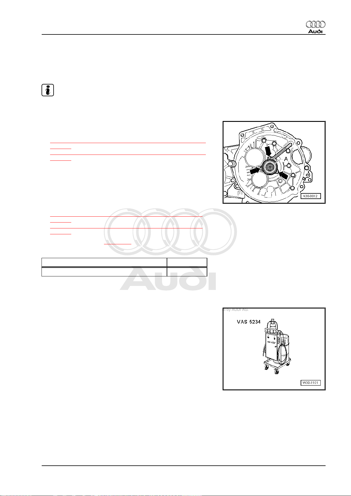
1.9 Bleeding clutch system
Special tools and workshop equipment required
♦ Brake charge and bleed equipment -VAS 5234-
Brake fluid specification ⇒ Brake system; Rep. Gr. 47 .
1. Servicing clutch mechanism 21
Page 28
Protected by copyright. Copying for private or commercial purposes, in part or in whole, is not
permitted unless authorised by AUDI AG. AUDI AG does not guarantee or accept any liability
with respect to the correctness of information in this document. Copyright by AUDI AG.
Audi TT 1999 ➤
5/6-speed manual gearbox 02M/02Y, four-wheel drive - Edition 12.2004
Procedure
Note
♦
The clutch system must be bled after performing work on the
hydraulic clutch mechanism.
♦
It is not necessary to prefill the system.
♦
When performing the following steps, make sure that no brake
fluid escapes onto the gearbox.
– Pull clutch pedal back to its normal rest position.
– Connect brake charge and bleed equipment -VAS 5234- to
brake fluid reservoir (do not switch on at this stage).
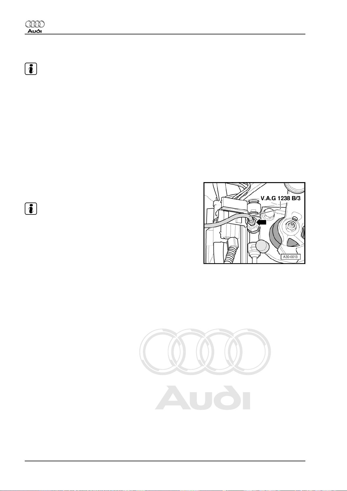
– If necessary, use bleed hose -V.A.G 1238 B/3- (670 mm) to
bleed system.
– Connect bleed hose to collector bottle of brake charge and
bleed equipment -VAS 5234- .
– Connect bleed hose -V.A.G 1238 B/3- to bleeder valve
-arrow-.
Note
Ensure that bleed hose is correctly fitted during bleeding opera‐
tion.
– Open bleeder valve -arrow-.
– Switch on bleeding equipment.
• Operating pressure 2.0 bar
–
Bleed off about 100 cm3 of brake fluid.
– Close bleeder valve.
– Rapidly operate clutch pedal from stop to stop 15 times.
–
Bleed off an additional 50 cm3 of brake fluid.
– Close bleeder valve. Tightening torque 4.5 Nm.
– Depress clutch pedal several times after bleeding process is
completed.
– Bleed system once again if necessary.
– Remove bleed hose and fit protective cap.
– Remove brake charge and bleed equipment -VAS 5234- from
brake fluid reservoir.
22 Rep. Gr.30 - Clutch
Page 29
Protected by copyright. Copying for private or commercial purposes, in part or in whole, is not
permitted unless authorised by AUDI AG. AUDI AG does not guarantee or accept any liability
with respect to the correctness of information in this document. Copyright by AUDI AG.
Audi TT 1999 ➤
5/6-speed manual gearbox 02M/02Y, four-wheel drive - Edition 12.2004
2 Servicing clutch release mechanism
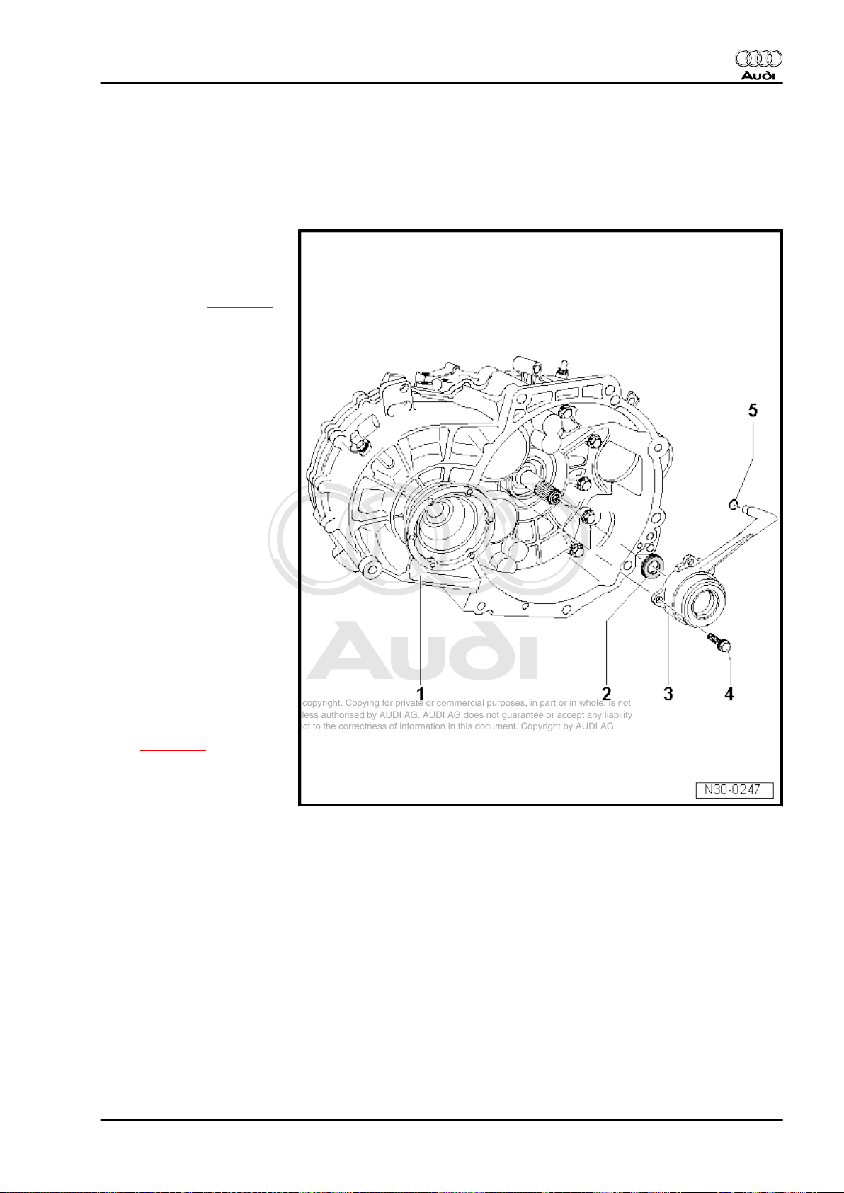
2.1 Clutch release mechanism - exploded view of components
1 - Gearbox
2 - Oil seal
❑ For input shaft
❑ Renewing ⇒ page 23
3 - Release bearing with hy‐
draulic actuator
❑ One unit; can only re re‐
newed together
❑ Do not wash out bear‐
ing; wipe clean only
❑ Renew complete re‐
lease bearing with hy‐
draulic actuator if noises
occur.
❑ Removing and installing
⇒ page 21
4 - Bolt, 12 Nm
❑ 3 x
❑ For correct version
check engine code and
refer to ⇒ Parts cata‐
logue
5 - Seal/O-ring
❑ Renew; for correct ver‐
sion refer to ⇒ Parts
catalogue
❑ Whether a seal or an O-
ring is used depends on
the type of connection
⇒ page 17 .
❑ Lubricate with brake flu‐
id before installing
❑ Push onto pipe connec‐
tion
2.2 Renewing input shaft oil seal
Special tools and workshop equipment required
2. Servicing clutch release mechanism 23
Page 30
Protected by copyright. Copying for private or commercial purposes, in part or in whole, is not
permitted unless authorised by AUDI AG. AUDI AG does not guarantee or accept any liability
with respect to the correctness of information in this document. Copyright by AUDI AG.
Audi TT 1999 ➤
5/6-speed manual gearbox 02M/02Y, four-wheel drive - Edition 12.2004
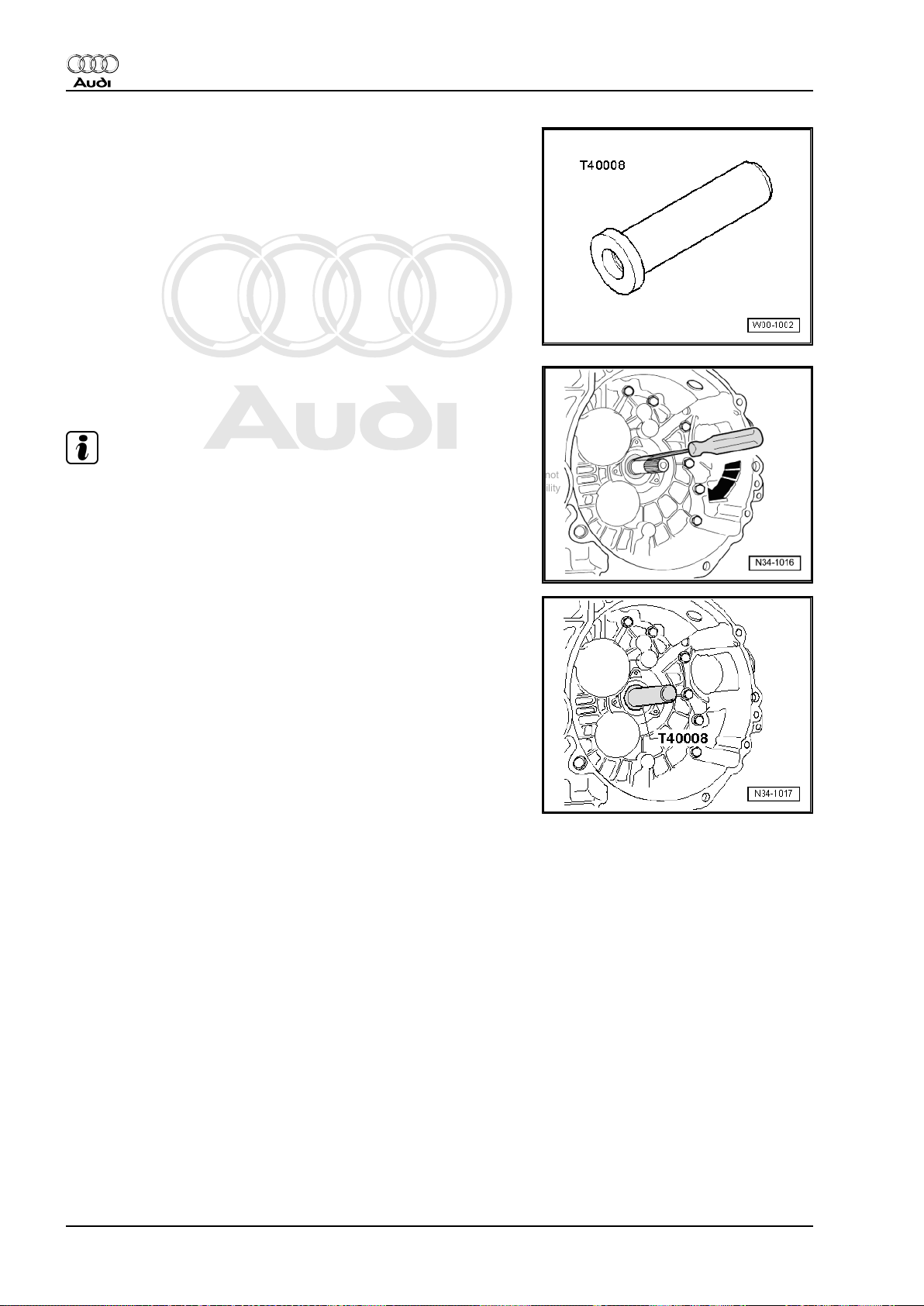
♦ Thrust piece -T40008-
Procedure
– Prise out input shaft oil seal carefully using a screwdriver.
Note
Take care not to damage contact surface for oil seal on input
shaft.
– Drive in new oil seal with thrust piece -T40008- as far as the
stop.
– Pack space between sealing lip and dust lip half-full with seal‐
ing grease -G 052 128 A1- .
24 Rep. Gr.30 - Clutch
Page 31

Protected by copyright. Copying for private or commercial purposes, in part or in whole, is not
permitted unless authorised by AUDI AG. AUDI AG does not guarantee or accept any liability
with respect to the correctness of information in this document. Copyright by AUDI AG.
Audi TT 1999 ➤
5/6-speed manual gearbox 02M/02Y, four-wheel drive - Edition 12.2004
3 Servicing conventional clutch
3.1 Conventional clutch - exploded view of components
Note
Select the correct pressure plate and clutch plate according to engine code ⇒ Parts catalogue .
1 - Dual-mass flywheel
❑ Observe instructions for
removal ⇒ page 26
❑ Removing and installing
⇒ Rep. Gr. 13
❑ Ensure that dowel pins
fit tightly
❑ Contact surface for
clutch lining must be
free of grooves, oil and
grease
2 - Clutch plate
❑ Removing and installing
⇒ page 27
❑ Installation position:
Shorter end of hub
-arrow- faces towards
pressure plate
❑ Clutch plate diameter
⇒ page 2
3 - Pressure plate
❑ Removing and installing
⇒ page 27
❑ Check ends of dia‐
phragm spring
⇒ page 26
❑ Check spring connec‐
tions and rivet joints
⇒ page 26
4 - M6 = 13 Nm; M7 = 20 Nm;
M8 = 22 Nm
❑ Working clockwise,
slacken all bolts one af‐
ter the other in steps of
90° (1/4 turn) until the
pressure plate is free
❑ Observe instructions for installation ⇒ page 29
❑ For correct version check engine code and refer to ⇒ Parts catalogue
3. Servicing conventional clutch 25
Page 32

Protected by copyright. Copying for private or commercial purposes, in part or in whole, is not
permitted unless authorised by AUDI AG. AUDI AG does not guarantee or accept any liability
with respect to the correctness of information in this document. Copyright by AUDI AG.
Audi TT 1999 ➤
5/6-speed manual gearbox 02M/02Y, four-wheel drive - Edition 12.2004
Checking ends of diaphragm spring
• Wear up to half the thickness of the diaphragm spring is per‐
missible.
Note
Select the correct pressure plate and clutch plate according to
engine code ⇒ Parts catalogue .
Checking spring connections and rivets
– Check spring connections between pressure plate and cover
for cracks and make sure rivets are seated tightly.
• Renew pressure plate if spring connections are damaged or
rivets are loose -arrows-.
Instructions for removing dual-mass flywheel
Note
Do not use an impact wrench or pneumatic wrench to remove
bolts -B-: this would severely damage the dual-mass flywheel.
The bolts must always be removed by hand.
– Rotate dual-mass flywheel -A- so that the bolts are aligned
centrally behind the holes -arrows-.
– When removing the bolts, make sure that none of the bolt
heads contacts the dual-mass flywheel, as this would damage
the flywheel when the bolts are unscrewed further.
26 Rep. Gr.30 - Clutch
Page 33

Protected by copyright. Copying for private or commercial purposes, in part or in whole, is not
permitted unless authorised by AUDI AG. AUDI AG does not guarantee or accept any liability
with respect to the correctness of information in this document. Copyright by AUDI AG.
5/6-speed manual gearbox 02M/02Y, four-wheel drive - Edition 12.2004
3.2 Removing and installing conventional clutch
Special tools and workshop
equipment required
♦ Counterhold tool -3067-
♦ Centring mandrel -3190 A-
♦ Centring mandrel -T10097-
for clutch plate with larger
hub diameter
♦ Grease for clutch plate
splines -G 000 100-
Audi TT 1999 ➤
Removing
– Remove gearbox
⇒ “2.1 Removing gearbox - vehicles with 4-cylinder engine”,
page 56 or
⇒ “2.3 Removing gearbox - vehicles with 6-cylinder engine”,
page 75 .
– Apply counter-hold tool -3067- in order to loosen bolts.
To prevent the pressure plate from becoming distorted during re‐
moval (causes clutch grab when driving off), always adhere to the
following procedure when unbolting the pressure plate:
– Working clockwise, loosen all six bolts consecutively in steps
of 90° (1/4 turn) until the pressure plate is released.
– Take off pressure plate and clutch plate.
Installing
Installation is carried out in reverse sequence; note the following:
3. Servicing conventional clutch 27
Page 34

Protected by copyright. Copying for private or commercial purposes, in part or in whole, is not
permitted unless authorised by AUDI AG. AUDI AG does not guarantee or accept any liability
with respect to the correctness of information in this document. Copyright by AUDI AG.
Audi TT 1999 ➤
5/6-speed manual gearbox 02M/02Y, four-wheel drive - Edition 12.2004
Note
♦
Select the correct clutch plate and pressure plate according to
engine code: ⇒ Parts catalogue .
♦
If the clutch has burnt out, thoroughly clean the bell housing,
flywheel and parts of the engine facing the gearbox in order to
prevent odours.
♦
Clean input shaft splines and (in the case of a used clutch
plate) the hub splines. Remove corrosion and apply only a very
thin coating of grease for clutch plate splines -G 000 100- to
the splines. Then move clutch plate backwards and forwards
on input shaft until hub moves freely on shaft. It is important
to remove excess grease.
♦
Pressure plates have an anti-corrosion coating and are
greased. Only the contact surface may be cleaned, otherwise
the service life of the clutch will be considerably reduced.
♦
Pressure plate contact surface and clutch plate lining must
make full contact with flywheel. Only then insert bolts.
– Note correct installation position of clutch plate:
• The marking “Getriebeseite” or “Getr.-Seite” (gearbox side)
-arrow- faces pressure plate and gearbox.
– Reverse position of counter-hold tool -3067- when installing.
– Use centring mandrel -3190 A- to centralise clutch plate.
28 Rep. Gr.30 - Clutch
Page 35

Protected by copyright. Copying for private or commercial purposes, in part or in whole, is not
permitted unless authorised by AUDI AG. AUDI AG does not guarantee or accept any liability
with respect to the correctness of information in this document. Copyright by AUDI AG.
5/6-speed manual gearbox 02M/02Y, four-wheel drive - Edition 12.2004
– Use centring mandrel -T10097- to centralise clutch plate with
larger hub diameter.
To prevent the pressure plate from becoming distorted during in‐
stallation (causes clutch grab when driving off), always adhere to
the following procedure when installing the pressure plate:
– Fit pressure plate onto dowel pins.
– Screw in all 6 bolts evenly by hand until bolt heads make con‐
tact with pressure plate.
– Working clockwise, tighten all six bolts consecutively in steps
of 90° (1/4 turn) until the housing makes contact with the fly‐
wheel.
– Working clockwise, tighten all 6 bolts to final torque consecu‐
tively.
– Install gearbox
⇒ “2.2 Installing gearbox - vehicles with 4-cylinder engine”,
page 67 or
⇒ “2.4 Installing gearbox - vehicles with 6-cylinder engine”,
page 87 .
Tightening torque
Audi TT 1999 ➤
Component Nm
Pressure plate to dual-mass flywheel M6 13
M7 20
M8 22
3. Servicing conventional clutch 29
Page 36

Protected by copyright. Copying for private or commercial purposes, in part or in whole, is not
permitted unless authorised by AUDI AG. AUDI AG does not guarantee or accept any liability
with respect to the correctness of information in this document. Copyright by AUDI AG.
Audi TT 1999 ➤
5/6-speed manual gearbox 02M/02Y, four-wheel drive - Edition 12.2004
4 Servicing self-adjusting clutch
4.1 Self-adjusting clutch (Sachs version) - exploded view of components
Caution
On this type of clutch the pressure plate and clutch plate can
only be renewed together.
1 - M6 = 13 Nm; M7 = 20 Nm;
M8 = 22 Nm
❑ Working clockwise,
slacken all bolts one af‐
ter the other in steps of
90° (1/4 turn) until the
pressure plate is free
❑ Observe instructions for
installation ⇒ page 35
❑ For correct version
check engine code and
refer to ⇒ Parts cata‐
logue
2 - Pressure plate
❑ Self-adjusting
❑ Identification
⇒ page 31
❑ Always renew clutch
plate as well
❑ Removing and installing
⇒ page 33
❑ Check ends of dia‐
phragm spring
⇒ page 31
❑ Check spring connec‐
tions and rivets
⇒ page 31
❑ Check wire ring
⇒ page 32
3 - Clutch plate
❑ Always renew pressure
plate as well
❑ Removing and installing
⇒ page 33
❑ Installation position: marking “Getriebeseite”/gearbox side (if provided) goes towards pressure plate and
gearbox; damper assembly (coil springs) (if provided) goes towards pressure plate and gearbox.
❑ Clutch lining must make full contact with flywheel.
❑ Clutch plate diameter ⇒ page 2
4 - Bolt for dual-mass flywheel
❑ Renew
❑ Observe instructions for removal ⇒ page 32
❑ Tightening torque ⇒ Rep. Gr. 13
30 Rep. Gr.30 - Clutch
Page 37

Protected by copyright. Copying for private or commercial purposes, in part or in whole, is not
permitted unless authorised by AUDI AG. AUDI AG does not guarantee or accept any liability
with respect to the correctness of information in this document. Copyright by AUDI AG.
5/6-speed manual gearbox 02M/02Y, four-wheel drive - Edition 12.2004
5 - Dual-mass flywheel
❑ Observe instructions for removal ⇒ page 32
❑ Removing and installing ⇒ Rep. Gr. 13
❑ Ensure that dowel pins fit tightly
❑ Contact surface for clutch lining must be free of grooves, oil and grease
6 - Not fitted
Identification of self-adjusting Sachs version clutch
♦ Pressure plate with stop mechanism (position sensor)
-arrow-.
Audi TT 1999 ➤
Checking ends of diaphragm spring
• Wear up to half the thickness of the diaphragm spring is per‐
missible.
Note
Select the correct pressure plate and clutch plate according to
engine code ⇒ Parts catalogue .
Checking spring connections and rivets
– Check spring connections -arrows A- for damage and make
sure riveted joints -arrows B- are seated tightly.
• Renew pressure plate if spring connections are broken or bad‐
ly bent, or if riveted joints are loose.
4. Servicing self-adjusting clutch 31
Page 38

Protected by copyright. Copying for private or commercial purposes, in part or in whole, is not
permitted unless authorised by AUDI AG. AUDI AG does not guarantee or accept any liability
with respect to the correctness of information in this document. Copyright by AUDI AG.
Audi TT 1999 ➤
5/6-speed manual gearbox 02M/02Y, four-wheel drive - Edition 12.2004
Checking wire ring
– Check that wire ring in pressure plate -arrow- is not damaged.
• Renew pressure plate if wire ring is broken.
Instructions for removing dual-mass flywheel
Note
Do not use an impact wrench or pneumatic wrench to remove
bolts -B-: this would severely damage the dual-mass flywheel.
The bolts must always be removed by hand.
– Rotate dual-mass flywheel -A- so that the bolts are aligned
centrally behind the holes -arrows-.
– When removing the bolts, make sure that none of the bolt
heads contacts the dual-mass flywheel, as this would damage
the flywheel when the bolts are unscrewed further.
32 Rep. Gr.30 - Clutch
Page 39

Protected by copyright. Copying for private or commercial purposes, in part or in whole, is not
permitted unless authorised by AUDI AG. AUDI AG does not guarantee or accept any liability
with respect to the correctness of information in this document. Copyright by AUDI AG.
Audi TT 1999 ➤
5/6-speed manual gearbox 02M/02Y, four-wheel drive - Edition 12.2004
4.2 Removing and installing self-adjusting clutch (Sachs version)
Special tools and workshop
equipment required
♦ Counterhold tool -3067-
♦ Centring mandrel -3190 A-
♦ Centring mandrel -T10097-
for clutch plate with larger
hub diameter
♦ Grease for clutch plate
splines -G 000 100-
Removing
– Remove gearbox
⇒ “2.1 Removing gearbox - vehicles with 4-cylinder engine”,
page 56 or
⇒ “2.3 Removing gearbox - vehicles with 6-cylinder engine”,
page 75 .
– Apply counter-hold tool -3067- in order to loosen bolts.
To prevent the pressure plate from becoming distorted during re‐
moval (causes clutch grab when driving off), always adhere to the
following procedure when unbolting the pressure plate:
– Working clockwise, loosen all six bolts consecutively in steps
of 90° (1/4 turn) until the pressure plate is released.
4. Servicing self-adjusting clutch 33
Page 40

Protected by copyright. Copying for private or commercial purposes, in part or in whole, is not
permitted unless authorised by AUDI AG. AUDI AG does not guarantee or accept any liability
with respect to the correctness of information in this document. Copyright by AUDI AG.
Audi TT 1999 ➤
5/6-speed manual gearbox 02M/02Y, four-wheel drive - Edition 12.2004
• Stop -2- with pin -1- should come loose when the bolts are
slackened.
– Take off pressure plate and clutch plate.
Installing
Installation is carried out in reverse sequence; note the following:
Note
♦
Select the correct clutch plate and pressure plate according to
engine code: ⇒ Parts catalogue .
♦
If the clutch has burnt out, thoroughly clean the bell housing,
flywheel and parts of the engine facing the gearbox in order to
prevent odours.
♦
Clean input shaft splines and (in the case of a used clutch
plate) the hub splines. Remove corrosion and apply only a very
thin coating of grease for clutch plate splines -G 000 100- to
the splines. Then move clutch plate backwards and forwards
on input shaft until hub moves freely on shaft. It is important
to remove excess grease.
♦
Pressure plates have an anti-corrosion coating and are
greased. Only the contact surface may be cleaned, otherwise
the service life of the clutch will be considerably reduced.
♦
Pressure plate contact surface and clutch plate lining must
make full contact with flywheel. Only then insert bolts.
– Reverse position of counter-hold tool -3067- when installing.
– Note correct installation position of clutch plate:
• Damper assembly (coil springs) or marking
“Getriebeseite” (gearbox side) faces pressure plate and gear‐
box.
– Use centring mandrel -3190 A- to centralise clutch plate.
– Use centring mandrel -T10097- to centralise clutch plate with
larger hub diameter.
34 Rep. Gr.30 - Clutch
Page 41

Protected by copyright. Copying for private or commercial purposes, in part or in whole, is not
permitted unless authorised by AUDI AG. AUDI AG does not guarantee or accept any liability
with respect to the correctness of information in this document. Copyright by AUDI AG.
5/6-speed manual gearbox 02M/02Y, four-wheel drive - Edition 12.2004
To prevent the pressure plate from becoming distorted during in‐
stallation (causes clutch grab when driving off), always adhere to
the following procedure when installing the pressure plate:
– Fit pressure plate onto dowel pins.
– Make sure that the stop pin (position sensor) -arrow- is free to
move.
– Screw in all 6 bolts evenly by hand until bolt heads make con‐
tact with pressure plate.
– Working clockwise, tighten all six bolts consecutively in steps
of 90° (1/4 turn) until the housing makes contact with the fly‐
wheel.
• The stop pin -arrow- should then lift away from the pressure
plate.
– Working clockwise, tighten all 6 bolts to final torque consecu‐
tively.
– Install gearbox
⇒ “2.2 Installing gearbox - vehicles with 4-cylinder engine”,
page 67 or
⇒ “2.4 Installing gearbox - vehicles with 6-cylinder engine”,
page 87 .
Tightening torque
Audi TT 1999 ➤
Component Nm
Pressure plate to dual-mass flywheel M6 13
M7 20
M8 22
4. Servicing self-adjusting clutch 35
Page 42

Protected by copyright. Copying for private or commercial purposes, in part or in whole, is not
permitted unless authorised by AUDI AG. AUDI AG does not guarantee or accept any liability
with respect to the correctness of information in this document. Copyright by AUDI AG.
Audi TT 1999 ➤
5/6-speed manual gearbox 02M/02Y, four-wheel drive - Edition 12.2004
4.3 Self-adjusting clutch (LuK version) - exploded view of components
1 - Dual-mass flywheel
❑ Observe instructions for
removal ⇒ page 37
❑ Removing and installing
⇒ Rep. Gr. 13
❑ Ensure that dowel pins
fit tightly
❑ Contact surface for
clutch lining must be
free of grooves, oil and
grease
2 - Clutch plate
❑ Removing and installing
⇒ page 38
❑ Always renew SAC
pressure plate as well
❑ Installation position:
marking
“Getriebeseite” (gear‐
box side) faces towards
gearbox
❑ Clutch plate diameter
⇒ page 2
3 - SAC pressure plate
❑ “SAC” = self adjusting
clutch
❑ Removing and installing
⇒ page 38
❑ Check ends of dia‐
phragm spring
⇒ page 37
❑ Check spring connec‐
tions and rivets
⇒ page 37
❑ Always renew clutch
plate as well
4 - M6 = 13 Nm; M7 = 20 Nm; M8 = 22 Nm
❑
Working clockwise, slacken all bolts one after the other in steps of 90° (1/4 turn) until the pressure plate
is free
❑ Observe instructions for installation ⇒ page 39
❑ For correct version check engine code and refer to ⇒ Parts catalogue
36 Rep. Gr.30 - Clutch
Page 43

Protected by copyright. Copying for private or commercial purposes, in part or in whole, is not
permitted unless authorised by AUDI AG. AUDI AG does not guarantee or accept any liability
with respect to the correctness of information in this document. Copyright by AUDI AG.
5/6-speed manual gearbox 02M/02Y, four-wheel drive - Edition 12.2004
Checking ends of diaphragm spring
• Wear up to half the thickness of the diaphragm spring
-arrows- is permissible.
Note
If required, pressure plate and clutch plate must always be re‐
newed together. Select the correct pressure plate and clutch plate
according to engine code ⇒ Parts catalogue .
Checking spring connections and rivets
– Check spring connections -arrows A- for damage and make
sure riveted joints -arrows B- are seated tightly.
• Renew pressure plate if spring connections are broken or bad‐
ly bent, or if riveted joints are loose.
Note
Audi TT 1999 ➤
If required, pressure plate and clutch plate must always be re‐
newed together. Select the correct pressure plate and clutch plate
according to engine code ⇒ Parts catalogue .
Instructions for removing dual-mass flywheel
Note
Do not use an impact wrench or pneumatic wrench to remove
bolts -B-: this would severely damage the dual-mass flywheel.
The bolts must always be removed by hand.
– Rotate dual-mass flywheel -A- so that the bolts are aligned
centrally behind the holes -arrows-.
– When removing the bolts, make sure that none of the bolt
heads contacts the dual-mass flywheel, as this would damage
the flywheel when the bolts are unscrewed further.
4. Servicing self-adjusting clutch 37
Page 44

Protected by copyright. Copying for private or commercial purposes, in part or in whole, is not
permitted unless authorised by AUDI AG. AUDI AG does not guarantee or accept any liability
with respect to the correctness of information in this document. Copyright by AUDI AG.
Audi TT 1999 ➤
5/6-speed manual gearbox 02M/02Y, four-wheel drive - Edition 12.2004
4.4 Removing and installing clutch (LuK version)
Special tools and workshop
equipment required
♦ Counterhold tool -3067-
♦ Centring mandrel -3190 A-
♦ Centring mandrel -T10097-
for clutch plate with larger
hub diameter
♦ Grease for clutch plate
splines -G 000 100-
Removing
– Remove gearbox
⇒ “2.1 Removing gearbox - vehicles with 4-cylinder engine”,
page 56 or
⇒ “2.3 Removing gearbox - vehicles with 6-cylinder engine”,
page 75 .
– Apply counter-hold tool -3067- in order to loosen bolts.
To prevent the pressure plate from becoming distorted during re‐
moval (causes clutch grab when driving off), always adhere to the
following procedure when unbolting the pressure plate:
– Working clockwise, loosen all six bolts consecutively in steps
of 90° (1/4 turn) until the pressure plate is released.
– Take off pressure plate and clutch plate.
Installing
Installation is carried out in reverse sequence; note the following:
38 Rep. Gr.30 - Clutch
Page 45

Protected by copyright. Copying for private or commercial purposes, in part or in whole, is not
permitted unless authorised by AUDI AG. AUDI AG does not guarantee or accept any liability
with respect to the correctness of information in this document. Copyright by AUDI AG.
5/6-speed manual gearbox 02M/02Y, four-wheel drive - Edition 12.2004
Note
♦
Renew clutch plate and pressure plate if riveted joints are
damaged or loose.
♦
If required, always renew clutch plate and pressure plate to‐
gether.
♦
Select the correct clutch plate and pressure plate according to
engine code: ⇒ Parts catalogue .
♦
If the clutch has burnt out, thoroughly clean the bell housing,
flywheel and parts of the engine facing the gearbox in order to
prevent odours.
♦
Clean input shaft splines and (in the case of a used clutch
plate) the hub splines. Remove corrosion and apply only a very
thin coating of grease for clutch plate splines -G 000 100- to
the splines. Then move clutch plate backwards and forwards
on input shaft until hub moves freely on shaft. It is important
to remove excess grease.
♦
Pressure plates have an anti-corrosion coating and are
greased. Only the contact surface may be cleaned, otherwise
the service life of the clutch will be considerably reduced.
♦
Pressure plate contact surface and clutch plate lining must
make full contact with flywheel. Only then insert bolts.
Audi TT 1999 ➤
– Note correct installation position of clutch plate:
• The marking “Getriebeseite” (gearbox side) faces towards the
gearbox
– Reverse position of counter-hold tool -3067- when installing.
– Use centring mandrel -3190 A- to centralise clutch plate or
centring mandrel -T10097- to centralise clutch plate with larger
hub diameter.
To prevent the pressure plate from becoming distorted during in‐
stallation (causes clutch grab when driving off), always adhere to
the following procedure when installing the pressure plate:
– Fit pressure plate onto dowel pins.
– Screw in all 6 bolts evenly by hand until bolt heads make con‐
tact with pressure plate.
– Working clockwise, tighten all six bolts consecutively in steps
of 90° (1/4 turn) until the housing makes contact with the fly‐
wheel.
– Working clockwise, tighten all 6 bolts to final torque consecu‐
tively.
– Install gearbox
⇒ “2.2 Installing gearbox - vehicles with 4-cylinder engine”,
page 67 or
⇒ “2.4 Installing gearbox - vehicles with 6-cylinder engine”,
page 87 .
Tightening torque
Component Nm
Pressure plate to dual-mass flywheel M6 13
M7 20
M8 22
4. Servicing self-adjusting clutch 39
Page 46

Protected by copyright. Copying for private or commercial purposes, in part or in whole, is not
permitted unless authorised by AUDI AG. AUDI AG does not guarantee or accept any liability
with respect to the correctness of information in this document. Copyright by AUDI AG.
Audi TT 1999 ➤
5/6-speed manual gearbox 02M/02Y, four-wheel drive - Edition 12.2004
34 – Controls, housing
1 Servicing selector mechanism
1.1 Installation position of selector mechanism
-Arrow A- gear selection movement
-Arrow B- gate selection movement
1 - Gear selector cable
❑ For gear selection
movement -arrow A-
2 - Gate selector cable
❑ For gate selection
movement -arrow B-
3 - Heat shield
4 - Relay lever
5 - Selector shaft lever with
damper weight
40 Rep. Gr.34 - Controls, housing
Page 47

Protected by copyright. Copying for private or commercial purposes, in part or in whole, is not
permitted unless authorised by AUDI AG. AUDI AG does not guarantee or accept any liability
with respect to the correctness of information in this document. Copyright by AUDI AG.
5/6-speed manual gearbox 02M/02Y, four-wheel drive - Edition 12.2004
I - Gear lever knob and boot exploded view of components
⇒ page 42
II - Gear lever and selector
housing - exploded view of
components ⇒ page 43
III - Selector cables
⇒ “1.4 Selector cables to
06.2001 - exploded view of
components”, page 45 or
⇒ “1.5 Selector cables from
07.2001 - exploded view of
components”, page 47
Removing and installing selec‐
tor mechanism ⇒ page 48
Adjusting selector mechanism
⇒ page 51
Audi TT 1999 ➤
1. Servicing selector mechanism 41
Page 48

Protected by copyright. Copying for private or commercial purposes, in part or in whole, is not
permitted unless authorised by AUDI AG. AUDI AG does not guarantee or accept any liability
with respect to the correctness of information in this document. Copyright by AUDI AG.
Audi TT 1999 ➤
5/6-speed manual gearbox 02M/02Y, four-wheel drive - Edition 12.2004
1.2 Gear lever knob and boot - exploded view of components
1 - Gear lever knob
❑ Unscrew to remove
2 - Socket head bolt
3 - Retaining ring
4 - Boot
❑ Removing ⇒ page 50
42 Rep. Gr.34 - Controls, housing
Page 49

Protected by copyright. Copying for private or commercial purposes, in part or in whole, is not
permitted unless authorised by AUDI AG. AUDI AG does not guarantee or accept any liability
with respect to the correctness of information in this document. Copyright by AUDI AG.
Audi TT 1999 ➤
5/6-speed manual gearbox 02M/02Y, four-wheel drive - Edition 12.2004
1.3 Gear lever and selector housing - exploded view of components
Note
Lubricate all bearings and moving surfaces with polycarbamide grease -G 052 142 A2- .
1 - Torx socket head bolt, 6 Nm
2 - Cover
3 - Gear lever
4 - Damper
5 - Bearing shell
❑ Insert in damper
⇒ Item 4 (page 43)
❑ Press onto gear lever
⇒ Item 3 (page 43) to‐
gether with damper
⇒ Item 4 (page 43)
❑ Open side of bearing
cage faces towards se‐
lector housing
6 - Gasket
❑ Between selector hous‐
ing and floor
❑ Self-adhesive
❑ Bond to selector hous‐
ing
7 - Bracket
❑ Attached to body
8 - Bolt, 25 Nm
9 - Hexagon nut, 25 Nm
10 - Damper
❑ Press onto selector
housing
11 - Selector housing
12 - Bearing bush
❑ Only fits in one position.
13 - Pivot pin
14 - Guide bush
❑ Press onto selector housing
15 - Spring
❑ Installing ⇒ page 44
16 - Gate selector bracket
❑ Removing securing clip ⇒ page 44
17 - Torx socket head bolt, 6 Nm
18 - Floor plate
❑ Bend tabs open to remove
❑ Renew
1. Servicing selector mechanism 43
Page 50

Protected by copyright. Copying for private or commercial purposes, in part or in whole, is not
permitted unless authorised by AUDI AG. AUDI AG does not guarantee or accept any liability
with respect to the correctness of information in this document. Copyright by AUDI AG.
Audi TT 1999 ➤
5/6-speed manual gearbox 02M/02Y, four-wheel drive - Edition 12.2004
19 - Securing clip
20 - Gate selector cable
❑ On gate selector bracket ⇒ Item 16 (page 43)
❑ Installation position ⇒ page 40
21 - Gear selector cable
❑ Press onto gear lever guide
❑ Installation position ⇒ page 40
22 - Hexagon nut, 25 Nm
23 - Bearing bush
❑ Only fits in one position.
24 - Securing clip
Removing securing clip for gate selector bracket
– Lift tab in direction of -arrow-.
Installing spring
– Insert spring so that the spring extension -A- is under the pin
-arrow-.
– Then pull spring extension -B- up towards gear lever until it
lies on upper section of pin -arrow-.
44 Rep. Gr.34 - Controls, housing
Page 51

Protected by copyright. Copying for private or commercial purposes, in part or in whole, is not
permitted unless authorised by AUDI AG. AUDI AG does not guarantee or accept any liability
with respect to the correctness of information in this document. Copyright by AUDI AG.
5/6-speed manual gearbox 02M/02Y, four-wheel drive - Edition 12.2004
1.4 Selector cables to 06.2001 - exploded view of components
Note
Lubricate all bearings and moving surfaces with polycarbamide grease -G 052 142 A2- .
1 - Gate selector cable
❑ On gate selector brack‐
et
❑ Installation position
⇒ page 40
2 - Gear selector cable
❑ Press onto gear lever
guide
❑ Installation position
⇒ page 40
3 - Securing clip
4 - Selector housing
5 - Securing clip
❑ Take care not to dam‐
age selector cables
when removing.
6 - Support bracket
7 - Grommet
❑ For support bracket
mounting on gearbox
8 - Distance piece
9 - Hexagon bolt, 25 Nm
10 - Cable end-piece
❑ Secures gate selector
cable to relay lever
❑ Renewing ⇒ page 46
❑ Installing ⇒ page 46
❑ Release to install and
adjust selector mecha‐
nism ⇒ page 49
11 - Relay lever
❑ Installation position ⇒ page 46
❑ After installing, adjust selector mechanism ⇒ page 51
12 - Bearing bush
13 - Securing clip
14 - Slide block
15 - Selector shaft lever with damper weight
❑ Installation position ⇒ page 46
❑ Install so that gap in splines aligns with selector shaft
❑ After installing, adjust selector mechanism ⇒ page 51
Audi TT 1999 ➤
1. Servicing selector mechanism 45
Page 52

Protected by copyright. Copying for private or commercial purposes, in part or in whole, is not
permitted unless authorised by AUDI AG. AUDI AG does not guarantee or accept any liability
with respect to the correctness of information in this document. Copyright by AUDI AG.
Audi TT 1999 ➤
5/6-speed manual gearbox 02M/02Y, four-wheel drive - Edition 12.2004
16 - Hexagon nut, 25 Nm
17 - Cable end-piece
❑ Secures gear selector cable to selector shaft lever
❑ Renewing ⇒ page 46
❑ Installing ⇒ page 46
❑ Release to install and adjust selector mechanism ⇒ page 49
Installation positions of selector shaft lever, relay lever and lock‐
ing pin
1 - Locking mechanism for gear selector cable
2 - Locking mechanism for gate selector cable
3 - Selector shaft lever with damper weight
4 - Relay lever
- Relay lever locates in guide rail of selector shaft lever via slide
block -arrow-.
- Apply polycarbamide grease -G 052 142 A2-
5 - Locking pin
- To adjust selector mechanism, press locking pin into gearbox
⇒ page 51
6 - Reversing light switch -F4-
Renewing cable end-pieces
Note
Cable end-pieces must be renewed after being removed. Cable
end-pieces are damaged upon removal.
– Lever off gear selector cable -A- and gate selector cable -B-
using an open-ended spanner (13 mm) -1-.
Renewing cable end-pieces
– Apply a small amount of polycarbamide grease -G 052 142
A2- in ball sockets of cable end-piece -A- and gate cable endpiece -B-.
Note
The seals -arrows- outside the ball socket must be grease-free.
46 Rep. Gr.34 - Controls, housing
Page 53

Protected by copyright. Copying for private or commercial purposes, in part or in whole, is not
permitted unless authorised by AUDI AG. AUDI AG does not guarantee or accept any liability
with respect to the correctness of information in this document. Copyright by AUDI AG.
Audi TT 1999 ➤
5/6-speed manual gearbox 02M/02Y, four-wheel drive - Edition 12.2004
1.5 Selector cables from 07.2001 - exploded view of components
Note
Lubricate all bearings and moving surfaces with polycarbamide grease -G 052 142 A2- .
1 - Gear selector cable
❑ Connect to cable end-
piece
⇒ Item 18 (page 48)
❑ Installation position
⇒ page 40
2 - Gate selector cable
❑ Connect to cable end-
piece
⇒ Item 11 (page 47)
❑ Installation position
⇒ page 40
3 - Securing clip
❑ Renew
4 - Securing clip
❑ Take care not to dam‐
age selector cables
when removing.
❑ Renew
5 - Selector housing
6 - Hexagon bolt, 20 Nm
❑ 2 x
7 - Support bracket
8 - Grommet
❑ For support bracket
mounting on gearbox
9 - Distance piece
10 - Nut, 20 Nm
11 - Cable end-piece
❑ Secures gate selector
cable to relay lever
❑ Do not interchange with ⇒ Item 18 (page 48) ; different version ⇒ page 48
12 - Relay lever
❑ Installation position ⇒ page 48
❑ After installing, adjust selector mechanism ⇒ page 51
13 - Bearing bush
14 - Securing clip
❑ Renew after removing
15 - Slide block
16 - Selector shaft lever with damper weight
❑ Install so that gap in splines aligns with selector shaft
❑ Installation position ⇒ page 48
❑ After installing, adjust selector mechanism ⇒ page 51
1. Servicing selector mechanism 47
Page 54

Protected by copyright. Copying for private or commercial purposes, in part or in whole, is not
permitted unless authorised by AUDI AG. AUDI AG does not guarantee or accept any liability
with respect to the correctness of information in this document. Copyright by AUDI AG.
Audi TT 1999 ➤
5/6-speed manual gearbox 02M/02Y, four-wheel drive - Edition 12.2004
17 - Hexagon nut, 23 Nm
❑ Self-locking
❑ Renew
18 - Cable end-piece
❑ Secures gear selector cable to selector shaft lever
❑ Do not interchange with ⇒ Item 11 (page 47) ; different version ⇒ page 48
Allocation of cable-end pieces
The holes in the cable end-pieces have different diameters:
♦ Cable end-piece securing gear selector cable to selector shaft
lever: diameter -a- = 10 mm.
♦ Cable end-piece for gate selector cable to relay lever: diame‐
ter -a- = 8 mm.
Installation position of selector shaft lever and relay lever
1 - Selector shaft lever with damper weight
2 - Relay lever
- Relay lever locates in guide rail of selector shaft lever via slide
block -arrow-.
1.6 Removing and installing selector mech‐
anism
Removing
– Remove cover panel (front left) -arrows-.
48 Rep. Gr.34 - Controls, housing
Page 55

Protected by copyright. Copying for private or commercial purposes, in part or in whole, is not
permitted unless authorised by AUDI AG. AUDI AG does not guarantee or accept any liability
with respect to the correctness of information in this document. Copyright by AUDI AG.
5/6-speed manual gearbox 02M/02Y, four-wheel drive - Edition 12.2004
Vehicles with 4-cylinder engine:
– Detach air intake hose at throttle valve module -J338- (slacken
hose clip -4-).
– Unplug electrical connector for air mass meter -G70- -1-.
– If fitted, detach hose -5- from air cleaner housing.
– Remove bolts -2- and -3-.
– Take out air cleaner housing.
Vehicles with 6-cylinder engine:
– Detach air intake hose -2- at throttle valve module -J338- .
– Unplug electrical connector for air mass meter -G70- -3-.
– Remove bolts -1- and -4-.
– Move electrical wire -arrow- clear.
– Take out air cleaner housing.
Audi TT 1999 ➤
– Detach cable support bracket from gearbox -arrows-.
Vehicles to 06.2001:
– Release cable end-pieces for gate selector cable and gear
selector cable; push back collar as far as it will go in direction
of -arrow 1-, then turn anti-clockwise in direction of -arrow 2so that it engages.
– Pull selector cables out of cable end-pieces
1. Servicing selector mechanism 49
Page 56

Protected by copyright. Copying for private or commercial purposes, in part or in whole, is not
permitted unless authorised by AUDI AG. AUDI AG does not guarantee or accept any liability
with respect to the correctness of information in this document. Copyright by AUDI AG.
Audi TT 1999 ➤
5/6-speed manual gearbox 02M/02Y, four-wheel drive - Edition 12.2004
Vehicles from 07.2001:
– Unclip securing clip -1- from gear selector cable and securing
clip -2- from gate selector cable.
– Detach cable end-pieces with selector cables from selector
shaft lever and relay lever.
All models:
– Unscrew gear knob -1-.
– Remove bolts -2-.
– Lift off retaining ring -3- and boot -4-.
– Lift out switch console -1- and unplug electrical connectors
-2-.
– Carefully press retaining tabs -3- forward and lift out storage
compartment -4-.
– Remove front nuts -arrows- securing selector housing.
50 Rep. Gr.34 - Controls, housing
Page 57

Protected by copyright. Copying for private or commercial purposes, in part or in whole, is not
permitted unless authorised by AUDI AG. AUDI AG does not guarantee or accept any liability
with respect to the correctness of information in this document. Copyright by AUDI AG.
5/6-speed manual gearbox 02M/02Y, four-wheel drive - Edition 12.2004
– Remove rear nuts -arrows- securing selector housing.
– Disconnect exhaust system behind front exhaust pipe and re‐
move catalytic converter (2nd mechanic required) ⇒ Rep. Gr.
26 .
– Remove propshaft ⇒ 5/6-speed manual gearbox 02M, four-
wheel drive / final drive; Rep. Gr. 39 .
– Remove heat shield (front).
– Move selector housing downwards and remove together with
selector cables.
Installing
Installation is carried out in reverse sequence; note the following:
– Attach cable support bracket -arrows-.
– Align selector housing parallel to body.
Vehicles to 06.2001:
– Insert Bowden cables in unlocked cable end-pieces.
Audi TT 1999 ➤
Vehicles from 07.2001:
– Unclip securing clip -1- from gear selector cable and securing
clip -2- from gate selector cable.
All models:
– Install propshaft ⇒ 5/6-speed manual gearbox 02M, four-
wheel drive / final drive; Rep. Gr. 39 .
– Install exhaust system free of stress ⇒ Rep. Gr. 26 .
– Adjust selector mechanism ⇒ page 51 .
Tightening torques
Component Nm
Selector housing to body 25
Selector cable support bracket to gearbox 25
1.7 Adjusting selector mechanism
Special tools and workshop equipment required
♦ Locking pin -T10027-
1. Servicing selector mechanism 51
Page 58

Protected by copyright. Copying for private or commercial purposes, in part or in whole, is not
permitted unless authorised by AUDI AG. AUDI AG does not guarantee or accept any liability
with respect to the correctness of information in this document. Copyright by AUDI AG.
Audi TT 1999 ➤
5/6-speed manual gearbox 02M/02Y, four-wheel drive - Edition 12.2004
Requirements for adjustment
• Gear selector linkage must be in proper condition and undam‐
aged.
• Selector mechanism must move freely.
• Gearbox, clutch and clutch mechanism must be in proper con‐
dition.
• Gearbox in neutral.
Procedure
– Remove cover panel (front left) -arrows-.
Vehicles with 6-cylinder engine:
– Unclip protective cover -1- for wiring.
– Move fuse box holder upwards -arrows-.
All models:
– Release cable end-pieces for gate selector cable and gear
selector cable; push back collar as far as it will go in direction
of -arrow 1-, then turn anti-clockwise in direction of -arrow 2so that it engages.
52 Rep. Gr.34 - Controls, housing
Page 59

Protected by copyright. Copying for private or commercial purposes, in part or in whole, is not
permitted unless authorised by AUDI AG. AUDI AG does not guarantee or accept any liability
with respect to the correctness of information in this document. Copyright by AUDI AG.
5/6-speed manual gearbox 02M/02Y, four-wheel drive - Edition 12.2004
Gearboxes to approx. 04.2003:
– Lock selector shaft by pressing selector shaft lever -1- in di‐
rection of arrow -A- downwards into selector gate for 1st/2nd
gear.
– At the same time press locking pin -2- in direction of
-arrow B- into gearbox, until it engages.
• The selector shaft is then locked and can no longer be moved.
Gearboxes from approx. 04.2003:
– Lock selector shaft, by pressing selector shaft downwards in
direction of -arrow 1-.
– At the same time move angled rod -A- upwards in direction of
-arrow 3-. At the same time press angled rod in direction of
-arrow 2- into selector shaft until it engages.
• The selector shaft is then locked and can no longer be moved.
Audi TT 1999 ➤
All models:
– Unscrew gear knob -1-.
– Remove bolts -2-.
– Lift off retaining ring -3- and boot -4-.
– With gearbox in neutral, guide gear lever to the left into 1st/
2nd gear gate to lock gear lever.
– Lock gear lever in position with locking pin -T10027- .
1. Servicing selector mechanism 53
Page 60

Protected by copyright. Copying for private or commercial purposes, in part or in whole, is not
permitted unless authorised by AUDI AG. AUDI AG does not guarantee or accept any liability
with respect to the correctness of information in this document. Copyright by AUDI AG.
Audi TT 1999 ➤
5/6-speed manual gearbox 02M/02Y, four-wheel drive - Edition 12.2004
– Make sure that gate selector cable -1- and gear selector cable
-2- are located free of tension in the cable end-pieces -3-.
– Turn collars -4- as far as they will go in direction of -arrow- and
release.
• The spring presses the locking mechanism into normal posi‐
tion.
Gearboxes to approx. 04.2003:
– Pull locking pin -2- back to normal position (direction of
-arrow-).
• It should be possible to move selector shaft lever -1- in direc‐
tion of -arrow-.
Gearboxes from approx. 04.2003:
– Turn angled rod -A- back to initial position (direction of
-arrow 2-).
• The angled rod must now be pressed out of the gearbox in
direction of -arrow 1-.
54 Rep. Gr.34 - Controls, housing
Page 61

Protected by copyright. Copying for private or commercial purposes, in part or in whole, is not
permitted unless authorised by AUDI AG. AUDI AG does not guarantee or accept any liability
with respect to the correctness of information in this document. Copyright by AUDI AG.
5/6-speed manual gearbox 02M/02Y, four-wheel drive - Edition 12.2004
• It should be possible to move selector shaft in direction of
-arrow-.
All models:
– Pull locking pin -T10027- out of selector mechanism.
Checking gear lever setting
• The gear lever should rest in the 3rd/4th gear gate when the
gearbox is in neutral.
– Press clutch pedal.
– Select all gears several times.
– Check operation of reverse gear lock.
• The gear lever should return by itself from the reverse gear
gate to the 3rd / 4th gear gate.
If the gear lever sticks or baulks repeatedly when engaging a
gear, perform the adjustment procedure again.
– Install boot for gear lever.
– Screw gear knob onto gear lever.
Audi TT 1999 ➤
1. Servicing selector mechanism 55
Page 62

Protected by copyright. Copying for private or commercial purposes, in part or in whole, is not
permitted unless authorised by AUDI AG. AUDI AG does not guarantee or accept any liability
with respect to the correctness of information in this document. Copyright by AUDI AG.
Audi TT 1999 ➤
5/6-speed manual gearbox 02M/02Y, four-wheel drive - Edition 12.2004
2 Removing and installing gearbox
2.1 Removing gearbox - vehicles with 4-cylinder engine
Special tools and workshop
equipment required
♦ Support bracket -10-222 A-
♦ Hose clamps, up to Ø 25
mm -3094- (3x)
♦ Hooks -3004- (3x)
♦ Gearbox support -3282-
♦ Adjustment plate -3282/27-
♦ Engine and gearbox jack -
V.A.G 1383 A-
♦ Chain (2x)
Procedure
Note
All cable ties which are released or cut open when removing the
gearbox must be refitted in the same position when installing the
gearbox.
– Move gear lever to neutral.
56 Rep. Gr.34 - Controls, housing
Page 63

Protected by copyright. Copying for private or commercial purposes, in part or in whole, is not
permitted unless authorised by AUDI AG. AUDI AG does not guarantee or accept any liability
with respect to the correctness of information in this document. Copyright by AUDI AG.
5/6-speed manual gearbox 02M/02Y, four-wheel drive - Edition 12.2004
– Press pin -2- inwards to remove fasteners -1- on lock carrier.
Do not press pin all the way down (not more than approx. 4
mm). Then lift out fastener.
– Remove cover panels -1- and -2- above lock carrier and bat‐
tery -arrows-.
Caution
Follow steps required when disconnecting battery ⇒ Electrical
system; Rep. Gr. 27 .
Audi TT 1999 ➤
– With ignition switched off, disconnect earth wire at battery.
TT Roadster:
WARNING
Hot steam or hot coolant may escape when opening expansion
tank. Cover filler cap with cloth and open carefully.
– Open filler cap on coolant expansion tank.
All models:
– Remove engine cover panel -1- above cylinder head cover
-arrows-.
– Detach air intake hose at throttle valve module -J338- (slacken
hose clip -4-).
– Unplug electrical connector for air mass meter -G70- -1-.
– If fitted, detach hose -5- from air cleaner housing.
– Remove bolts -2- and -3-.
– Take out air cleaner housing.
2. Removing and installing gearbox 57
Page 64

Protected by copyright. Copying for private or commercial purposes, in part or in whole, is not
permitted unless authorised by AUDI AG. AUDI AG does not guarantee or accept any liability
with respect to the correctness of information in this document. Copyright by AUDI AG.
Audi TT 1999 ➤
5/6-speed manual gearbox 02M/02Y, four-wheel drive - Edition 12.2004
– Remove battery and battery tray -arrows-.
– Detach cable support bracket from gearbox -arrows-.
Vehicles to 06.2001:
Caution
Do not remove cable end-pieces from selector shaft lever or
relay lever. Cable end-pieces must be renewed after removal.
– Release cable end-piece for gate selector cable (the cable on
the right as shown in the illustration); push back collar as far
as it will go in direction of -arrow 1-, then turn anti-clockwise in
direction of -arrow 2- so that it engages.
– Pull gate selector cable out of cable end-piece.
Vehicles from 07.2001:
– Detach securing clip -arrow 2- and remove relay lever -A- with
gate selector cable.
All models:
– Unscrew nut -arrow 1- for pressure pipe of power steering.
– Unscrew nut -arrow 3- and detach selector shaft lever -B- with
gear selector cable.
Note
If necessary, use puller -Kukko 20-10- to detach.
– Tie up gear selector cable with selector shaft lever and gate
selector cable.
58 Rep. Gr.34 - Controls, housing
Page 65

Protected by copyright. Copying for private or commercial purposes, in part or in whole, is not
permitted unless authorised by AUDI AG. AUDI AG does not guarantee or accept any liability
with respect to the correctness of information in this document. Copyright by AUDI AG.
5/6-speed manual gearbox 02M/02Y, four-wheel drive - Edition 12.2004
– Unplug electrical connector at speedometer sender -G22-
-arrow-.
– Unscrew earth wire -1-.
– Detach electrical connector -3- from starter. Pipe -4- remains
connected.
– Unplug connector -2- and pull out of bracket.
– Disengage wiring from bracket on starter and move clear to
one side.
– Remove bracket.
– Remove top bolt securing starter.
Audi TT 1999 ➤
– Unscrew engine/gearbox securing bolts which are accessible
from above.
Vehicles with two charge air coolers:
Note
Before removing, mark direction of operation of poly V-belt with
chalk or felt-tipped pen. Running a used belt in the opposite di‐
rection could destroy it.
– Move tensioner in direction of -arrow- to slacken poly V-belt.
– Detach poly V-belt.
2. Removing and installing gearbox 59
Page 66

Protected by copyright. Copying for private or commercial purposes, in part or in whole, is not
permitted unless authorised by AUDI AG. AUDI AG does not guarantee or accept any liability
with respect to the correctness of information in this document. Copyright by AUDI AG.
Audi TT 1999 ➤
5/6-speed manual gearbox 02M/02Y, four-wheel drive - Edition 12.2004
Vehicles with one charge air cooler:
– Detach air pipe leading to charge air cooler at longitudinal
member (bottom right) -arrows-.
All models:
– Remove both front wheels.
TT Coupé:
– Remove centre noise insulation -fasteners 1 ... 3-.
TT Roadster:
– Release fasteners in wheel housing (left and right).
– Remove bolts -arrows 1 ... 3-.
Note
-Arrows A and B- can be disregarded.
All models:
– Remove noise insulation (left-side) -arrows-.
60 Rep. Gr.34 - Controls, housing
Page 67

Protected by copyright. Copying for private or commercial purposes, in part or in whole, is not
permitted unless authorised by AUDI AG. AUDI AG does not guarantee or accept any liability
with respect to the correctness of information in this document. Copyright by AUDI AG.
5/6-speed manual gearbox 02M/02Y, four-wheel drive - Edition 12.2004
– Remove noise insulation (right-side) -arrows-.
Vehicles with two charge air coolers and TT Roadster:
– Remove tubular cross member -arrows-.
Audi TT 1999 ➤
Vehicles with two charge air coolers:
– Remove power steering pump pulley (counterhold with Allen
key).
All models:
– Clamp off supply hose and pressure hose at power steering
pump using hose clamps -3094- .
– Unplug electrical connector -1- on power steering pressure
switch.
– Unscrew pressure pipe -2- on power steering pump.
2. Removing and installing gearbox 61
Page 68

Protected by copyright. Copying for private or commercial purposes, in part or in whole, is not
permitted unless authorised by AUDI AG. AUDI AG does not guarantee or accept any liability
with respect to the correctness of information in this document. Copyright by AUDI AG.
Audi TT 1999 ➤
5/6-speed manual gearbox 02M/02Y, four-wheel drive - Edition 12.2004
– Detach power steering pipe from gearbox -arrows- and re‐
move speed nut from gearbox.
Note
If fitted, detach additional pipe retainer.
– Remove bottom bolt securing starter and take out starter.
– Using hose clamp -3094- , clamp off pressure line to clutch
slave cylinder.
– Pull up retaining clip -arrow- and pull pressure line -1- out of
hose connection.
Caution
Do not operate clutch pedal after disconnecting pressure line
from slave cylinder.
– Unplug electrical connector for reversing light switch -F4- -2-.
– Disconnect exhaust system at clamp -arrows-.
– Push clamp towards the rear.
– Tie up exhaust system with a chain. To do so, engage hooks
-3004- in openings on underbody (if necessary remove plugs).
Note
The flexible joint (de-coupling element) in the exhaust system
must not be bent more than 10° – otherwise it can be damaged.
62 Rep. Gr.34 - Controls, housing
Page 69

Protected by copyright. Copying for private or commercial purposes, in part or in whole, is not
permitted unless authorised by AUDI AG. AUDI AG does not guarantee or accept any liability
with respect to the correctness of information in this document. Copyright by AUDI AG.
5/6-speed manual gearbox 02M/02Y, four-wheel drive - Edition 12.2004
– Mark position of propshaft relative to flexible coupling on bevel
box.
– Unscrew propshaft from flexible coupling at bevel box
-arrows-.
Note
Counterhold with a lever on triangle flange when loosening the
bolts.
– Press propshaft horizontally to rear as far as possible.
Note
After loosening bolts -A- (⇒ following illustration N34-0712) the
engine/gearbox assembly will swing slightly to the front.
Caution
Audi TT 1999 ➤
Make sure that the seal -arrow- in the flange of the propshaft
is not damaged when removing and installing. If seals are
damaged, the propshaft must be renewed.
– First unscrew bolts -A- and then bolts -B- and remove pendu‐
lum support.
– Carefully press engine/gearbox assembly to front.
TT Roadster:
– Remove 8 bolts -1- with lock washers -2- and detach diagonal
struts.
2. Removing and installing gearbox 63
Page 70

Protected by copyright. Copying for private or commercial purposes, in part or in whole, is not
permitted unless authorised by AUDI AG. AUDI AG does not guarantee or accept any liability
with respect to the correctness of information in this document. Copyright by AUDI AG.
Audi TT 1999 ➤
5/6-speed manual gearbox 02M/02Y, four-wheel drive - Edition 12.2004
All models:
– If fitted, unbolt front bracket for exhaust system -arrow- from
subframe.
– Remove bolts -2- for steering box.
– Lever off steering box from subframe (dowel sleeve).
– Position engine and gearbox jack -V.A.G 1383 A- with engine
and universal support -V.A.G 1359/2- below subframe.
– Remove subframe bolts -1- and -3-.
– Carefully lower subframe and press steering box upwards at
the same time (do not detach subframe from swivel joints and
coupling rods).
– Tie up steering box.
– Remove drive shafts from gearbox flange shafts and place to
rear onto subframe (take care not to damage surface protec‐
tion).
– Use chain to tie subframe to rear (engage hook -3004- into
opening on underbody; if fitted, remove plug).
– Unscrew heat shield for drive shaft on right of bevel box
-arrows-.
Vehicles with bevel box bracket (metal casting):
– Unscrew bolts -A ... C- at bevel box bracket.
Note
It is not possible to remove bracket at this stage. Bracket remains
in installation position.
64 Rep. Gr.34 - Controls, housing
Page 71

Protected by copyright. Copying for private or commercial purposes, in part or in whole, is not
permitted unless authorised by AUDI AG. AUDI AG does not guarantee or accept any liability
with respect to the correctness of information in this document. Copyright by AUDI AG.
5/6-speed manual gearbox 02M/02Y, four-wheel drive - Edition 12.2004
Vehicles with bevel box bracket (sheet metal version):
– Remove bolts -A ... C- and take off bevel box bracket.
All models:
Note
The small cover plate -2- is fitted behind the bevel box and is not
visible with bevel box installed. Shown in illustration with gearbox
removed.
Audi TT 1999 ➤
– Remove bolt -1- (using 10 mm spanner) and remove flywheel
cover plate behind bevel box.
– Set up support bracket -10-222 A- with rack -10-222 A/1- on
wing mounting flanges -arrows-.
– Take up weight of engine/gearbox assembly via the spindle.
– Remove gearbox support (left-side), to do so unscrew bolts
-1- and -2-.
2. Removing and installing gearbox 65
Page 72

Protected by copyright. Copying for private or commercial purposes, in part or in whole, is not
permitted unless authorised by AUDI AG. AUDI AG does not guarantee or accept any liability
with respect to the correctness of information in this document. Copyright by AUDI AG.
Audi TT 1999 ➤
5/6-speed manual gearbox 02M/02Y, four-wheel drive - Edition 12.2004
– Lower the engine/gearbox assembly slightly using the spindle.
• The distance -a- between gearbox housing and gearbox
mounting should be 100 ... 110 mm.
To remove manual gearbox 02M set up gearbox support -3282with adjustment plate -3282/27- .
A - Support elements
B - Arrow points in direction of travel
– Assemble engine and gearbox jack -V.A.G 1383 A- as follows:
– Place adjustment plate -3282/27- on gearbox support -3282-
(adjustment plate only fits in one position).
– Attach support elements as illustrated on adjustment plate.
– Align arms of gearbox support according to holes in adjust‐
ment plate -3282/27- .
– Position engine and gearbox jack -V.A.G 1383 A- under vehi‐
cle; arrow symbol on the adjustment plate faces forward.
– Align the adjustment plate parallel to the gearbox.
– Secure support element to gearbox with bolt M8x25 -arrow-.
66 Rep. Gr.34 - Controls, housing
Page 73

Protected by copyright. Copying for private or commercial purposes, in part or in whole, is not
permitted unless authorised by AUDI AG. AUDI AG does not guarantee or accept any liability
with respect to the correctness of information in this document. Copyright by AUDI AG.
5/6-speed manual gearbox 02M/02Y, four-wheel drive - Edition 12.2004
– Unscrew bolt -arrow- above bevel box.
– Unscrew engine/gearbox securing bolts which are accessible
from below.
– Pull gearbox off dowel sleeves.
– Remove bevel box bracket.
– Pull the gearbox off engine first from the bevel box side and
then from the front side.
– Lower gearbox carefully.
Audi TT 1999 ➤
2.2 Installing gearbox - vehicles with 4-cyl‐
inder engine
Installation is carried out in reverse sequence; note the following:
Note
♦
Renew self-locking nuts and bolts when performing assembly
work.
♦
Renew oil seals and gaskets, and bolts which are tightened by
turning through a specified angle.
♦
Secure all hose connections with the correct hose clips (as
original equipment); refer to ⇒ Parts catalogue .
♦
All cable ties which are released or cut open during removal
must be fitted in the same position when installing.
– Clean input shaft splines and (in the case of used clutch plates)
the hub splines. Remove corrosion and apply only a very thin
coating of grease for clutch plate splines -G 000 100- to the
splines. It is important to remove excess grease.
• It should be possible to push the clutch plate back and forth
slightly on the input shaft.
– Check that dowel sleeves for centralising engine/gearbox are
in the cylinder block; install if necessary.
– Check clutch release bearing with hydraulic actuator for wear
and renew if necessary.
2. Removing and installing gearbox 67
Page 74

Protected by copyright. Copying for private or commercial purposes, in part or in whole, is not
permitted unless authorised by AUDI AG. AUDI AG does not guarantee or accept any liability
with respect to the correctness of information in this document. Copyright by AUDI AG.
Audi TT 1999 ➤
5/6-speed manual gearbox 02M/02Y, four-wheel drive - Edition 12.2004
– Engage intermediate plate at sealing flange and push onto
dowel sleeves -arrows-.
– Tilt gearbox to the left by turning spindles of gearbox support
-3282- .
– Raise gearbox carefully and move to installation position using
gearbox support.
– Push the gearbox over the engine flywheel at the front first
-arrow- and then at the bevel box side.
– Install gearbox.
Vehicles with bevel box bracket (metal casting):
– Install bevel box bracket prior to fitting engine/gearbox secur‐
ing bolts.
All models:
– Fit new engine/gearbox securing bolts which are accessible
from below. Tightening torques ⇒ page 69
68 Rep. Gr.34 - Controls, housing
Page 75

Protected by copyright. Copying for private or commercial purposes, in part or in whole, is not
permitted unless authorised by AUDI AG. AUDI AG does not guarantee or accept any liability
with respect to the correctness of information in this document. Copyright by AUDI AG.
5/6-speed manual gearbox 02M/02Y, four-wheel drive - Edition 12.2004
Vehicles with bevel box bracket (metal casting):
– Screw in bevel box bracket bolts -A ... C- only a few turns at
this stage.
– Observe the further tightening sequence:
1. First tighten bolts -A- to 3 Nm.
2. Tighten bolts -B- and -C- to 35 Nm.
3. Tighten bolts -A- to 45 Nm.
Vehicles with bevel box bracket (sheet metal version):
– Screw in bevel box bracket bolts -A ... C- only a few turns at
this stage.
– Observe the further tightening sequence:
1. First tighten bolts -A- to 3 Nm.
2. Tighten bolts -B- to 35 Nm.
Audi TT 1999 ➤
3. Tighten bolt -C- to 22 Nm.
4. Tighten bolts -A- to 45 Nm.
– Detach gearbox support -3282- from gearbox.
– If fitted, install small flywheel cover plate -A- at rear of bevel
box and secure bolt -arrow-.
– Fit new engine/gearbox securing bolts which are accessible
from above.
Engine/gearbox securing bolts
Item Bolt Nm
1, 2
3 1), 4
1)
1)
M12x55
M12x165
5 M10x105
6, 7 M10x50
8 M12x70
80
80
40
40
80
2)
2)
2)
2)
2)
A Dowel sleeves for centralising
1) Bolt with stud M8.
2) Renew bolts.
2. Removing and installing gearbox 69
Page 76

Protected by copyright. Copying for private or commercial purposes, in part or in whole, is not
permitted unless authorised by AUDI AG. AUDI AG does not guarantee or accept any liability
with respect to the correctness of information in this document. Copyright by AUDI AG.
Audi TT 1999 ➤
5/6-speed manual gearbox 02M/02Y, four-wheel drive - Edition 12.2004
– Use new bolts -1- when installing assembly mounting.
– Fit gearbox support to gearbox (pendulum support remains
removed).
– Pull gearbox up to gearbox support with spindle on support
bracket.
Caution
Before tightening the bolts, the support arm of the gearbox
mounting and the gearbox support must be aligned absolutely
parallel, otherwise the threads will be damaged. If necessary,
push gearbox up at the rear with trolley jack.
– Renew bolts -2-.
– Fit support arm of gearbox mounting to gearbox support.
WARNING
Support bracket -10-222 A- must not be removed until all bolts
on left and right assembly mountings have been tightened to
specified torque.
– Remove support bracket.
– Install subframe as follows:
– Move drive shafts in installation position and tighten hand-
tight.
– Move subframe into installation position.
– Fit subframe bolts.
– Place steering box onto subframe and fit steering box bolts.
• Threaded sleeve -1- must be positioned in hole in subframe
• Rubber buffer on opposite side must be positioned on corre‐
sponding projection on subframe.
– Secure steering box ⇒ Running gear, front-wheel drive and
four-wheel drive; Rep. Gr. 48 .
– Secure subframe with new bolts ⇒ Running gear, front-wheel
drive and four-wheel drive; Rep. Gr. 48 .
– Bolt drive shafts to gearbox flange shafts ⇒ Running gear,
front-wheel drive and four-wheel drive; Rep. Gr. 40 .
TT Roadster:
– Install diagonal struts ⇒ Running gear, front-wheel drive and
four-wheel drive; Rep. Gr. 40 .
70 Rep. Gr.34 - Controls, housing
Page 77

Protected by copyright. Copying for private or commercial purposes, in part or in whole, is not
permitted unless authorised by AUDI AG. AUDI AG does not guarantee or accept any liability
with respect to the correctness of information in this document. Copyright by AUDI AG.
5/6-speed manual gearbox 02M/02Y, four-wheel drive - Edition 12.2004
All models:
– Install heat shield for drive shaft (right-side) -arrows-.
– Secure pendulum support to gearbox with new bolts
-arrows B-.
– Press engine/gearbox assembly towards bulkhead; the bevel
box pin must be guided carefully into the propshaft flange
when doing this.
Audi TT 1999 ➤
– Slide propshaft onto guide pin without tilting.
Caution
Make sure that the seal -arrow- in the flange of the propshaft
is not damaged when removing and installing. If seals are
damaged, the propshaft must be renewed.
– Secure pendulum support to subframe with new bolts
-arrows A-.
2. Removing and installing gearbox 71
Page 78

Protected by copyright. Copying for private or commercial purposes, in part or in whole, is not
permitted unless authorised by AUDI AG. AUDI AG does not guarantee or accept any liability
with respect to the correctness of information in this document. Copyright by AUDI AG.
Audi TT 1999 ➤
5/6-speed manual gearbox 02M/02Y, four-wheel drive - Edition 12.2004
– Bolt propshaft to flexible coupling on bevel box -arrows- ⇒ 5/6-
speed manual gearbox 02M, four-wheel drive / final drive;
Rep. Gr. 39 .
– Install exhaust system free of stress ⇒ Rep. Gr. 26 .
– Press pressure pipe -1- into hose connector and lock in posi‐
tion with retaining clip.
Caution
Do not press clutch pedal before clutch system has been bled.
– Remove hose clamp -3094- .
– Attach electrical connector for reversing light switch -F4- -2-.
– Install starter and fit bottom bolt. Tightening torques
⇒ page 69
– Fit power steering pipe to gearbox -arrows-.
72 Rep. Gr.34 - Controls, housing
Page 79

Protected by copyright. Copying for private or commercial purposes, in part or in whole, is not
permitted unless authorised by AUDI AG. AUDI AG does not guarantee or accept any liability
with respect to the correctness of information in this document. Copyright by AUDI AG.
5/6-speed manual gearbox 02M/02Y, four-wheel drive - Edition 12.2004
– Fit pressure pipe -2- to power steering pump with new seals
⇒ Running gear, front-wheel drive and four-wheel drive; Rep.
Gr. 48 .
– Remove hose clamps -3094- .
– Attach electrical connector -1- for power steering pressure
switch.
Vehicles with two charge air coolers:
– Fit power steering pump pulley and poly V-belt pulley ⇒ Run‐
ning gear, front-wheel drive and four-wheel drive; Rep. Gr.
48 .
Vehicles with two charge air coolers and TT Roadster:
– Install tubular cross member ⇒ General body repairs, exterior;
Rep. Gr. 50 .
All models:
– Check gear oil in manual gearbox with bevel box
⇒ page 115 .
– Install noise insulation panels ⇒ General body repairs, exte‐
rior; Rep. Gr. 50 .
Vehicles with one charge air cooler:
– Attach air pipe leading to charge air cooler at longitudinal
member (bottom right).
All models:
– Install top bolt securing starter. Tightening torque ⇒ page 69
Audi TT 1999 ➤
– Attach electrical connector -3-.
– Fit bracket -2-, attach wiring and engage connector in bracket.
– Fit earth wire -1-.
– Fit selector shaft lever -B- with gear selector cable on selector
shaft (tighten nut -arrow 3-).
– Install relay lever -A- with gate selector cable (insert securing
clip -arrow 2-).
– Tighten nut -arrow 1-.
2. Removing and installing gearbox 73
Page 80

Protected by copyright. Copying for private or commercial purposes, in part or in whole, is not
permitted unless authorised by AUDI AG. AUDI AG does not guarantee or accept any liability
with respect to the correctness of information in this document. Copyright by AUDI AG.
Audi TT 1999 ➤
5/6-speed manual gearbox 02M/02Y, four-wheel drive - Edition 12.2004
– Attach cable support bracket to gearbox -arrows-.
– Plug in electrical connector at speedometer sender -G22-
-arrow-.
– Make sure that mountings of engine/gearbox assembly are
free of tension when installing ⇒ Rep. Gr. 10 .
– Bleed clutch system ⇒ page 21 .
– Adjust selector mechanism ⇒ page 51 .
– Install battery tray and battery; follow steps required after con‐
necting battery ⇒ Electrical system; Rep. Gr. 27 .
– Install air cleaner housing.
– Attach engine cover panel.
Tightening torques
Component Nm
Flywheel cover plate to gearbox 10
Gearbox support to gearbox
Gearbox support to gearbox mounting
Pendulum supporttogearbox
40 + 90° 3)
60 + 90° 3)
40 + 90° 3)
subframe
20 + 90° 3)
Heat shield to gearbox 25
Flywheel cover plate to gearbox 10
Pressure pipe of power steering to gearbox
22
support
Selector cable support bracket to gearbox 23
Selector shaft lever to selector shaft
20
Air cleaner housing to body 10
Air pipe to longitudinal member 10
3) Renew bolts.
4) 90° = one quarter turn.
5) Renew nut.
4)
4)
4)
4)
5)
74 Rep. Gr.34 - Controls, housing
Page 81

Protected by copyright. Copying for private or commercial purposes, in part or in whole, is not
permitted unless authorised by AUDI AG. AUDI AG does not guarantee or accept any liability
with respect to the correctness of information in this document. Copyright by AUDI AG.
5/6-speed manual gearbox 02M/02Y, four-wheel drive - Edition 12.2004
2.3 Removing gearbox - vehicles with 6-cylinder engine
Special tools and workshop
equipment required
♦ Support bracket -10-222 A-
♦ Rack -10-222 A /1-
♦ Engine and gearbox jack -
V.A.G 1383 A-
♦ Gearbox support -3282-
♦ Shackle -10-222 A /12-
♦ Hose clamps, up to Ø 25
mm -3094-
Audi TT 1999 ➤
2. Removing and installing gearbox 75
Page 82

Protected by copyright. Copying for private or commercial purposes, in part or in whole, is not
permitted unless authorised by AUDI AG. AUDI AG does not guarantee or accept any liability
with respect to the correctness of information in this document. Copyright by AUDI AG.
Audi TT 1999 ➤
5/6-speed manual gearbox 02M/02Y, four-wheel drive - Edition 12.2004
♦ Adjustment plate -3282/27-
♦ Hooks -3004-
♦ Drip tray for workshop hoist
-VAS 6208- (TT Roadster
only)
Procedure
Note
All cable ties which are released or cut open when removing the
gearbox must be refitted in the same position when installing the
gearbox.
– Move gear lever to neutral.
Caution
Follow steps required when disconnecting battery ⇒ Electrical
system; Rep. Gr. 27 .
76 Rep. Gr.34 - Controls, housing
Page 83

Protected by copyright. Copying for private or commercial purposes, in part or in whole, is not
permitted unless authorised by AUDI AG. AUDI AG does not guarantee or accept any liability
with respect to the correctness of information in this document. Copyright by AUDI AG.
5/6-speed manual gearbox 02M/02Y, four-wheel drive - Edition 12.2004
– With ignition switched off, disconnect earth wire -arrow- at
battery in luggage compartment under floor cover.
TT Roadster:
WARNING
Hot steam or hot coolant may escape when opening expansion
tank. Cover filler cap with cloth and open carefully.
– Open filler cap on coolant expansion tank.
All models:
– Press pin -2- inwards to remove fasteners -1- on lock carrier.
Do not press pin all the way down (not more than approx. 4
mm). Then lift out fastener.
Audi TT 1999 ➤
– Remove cover panels -1- and -2- (left-side) above lock carrier
and main fuse box -arrows-.
– Detach air intake hose -2- at throttle valve module -J338- .
– Unplug electrical connector for air mass meter -G70- -3-.
– Remove bolts -1- and -4-.
– Move electrical wire -arrow- clear.
– Take out air cleaner housing.
2. Removing and installing gearbox 77
Page 84

Protected by copyright. Copying for private or commercial purposes, in part or in whole, is not
permitted unless authorised by AUDI AG. AUDI AG does not guarantee or accept any liability
with respect to the correctness of information in this document. Copyright by AUDI AG.
Audi TT 1999 ➤
5/6-speed manual gearbox 02M/02Y, four-wheel drive - Edition 12.2004
– Unclip protective cover -1- for wiring.
– Move fuse box holder upwards -arrows-.
– Remove fuse box (release retaining tabs -arrow-).
Note
Wiring remains connected.
– Remove fuse box carrier -arrows-.
– Detach cable support bracket from gearbox -arrows-.
78 Rep. Gr.34 - Controls, housing
Page 85

Protected by copyright. Copying for private or commercial purposes, in part or in whole, is not
permitted unless authorised by AUDI AG. AUDI AG does not guarantee or accept any liability
with respect to the correctness of information in this document. Copyright by AUDI AG.
5/6-speed manual gearbox 02M/02Y, four-wheel drive - Edition 12.2004
– Unscrew nut -arrow 1- for pressure pipe of power steering.
– Detach securing clip -arrow 2- and remove relay lever -A- with
gate selector cable.
– Unscrew nut -arrow 3- and detach selector shaft lever -B- with
gear selector cable.
Note
If necessary, use puller -Kukko 20-10- to detach.
– Tie up gear selector cable with selector shaft lever and gate
selector cable with relay lever to one side.
– Unplug electrical connector at speedometer sender -G22-
-arrow-.
Audi TT 1999 ➤
– Unscrew earth wire -1-.
– Detach electrical connector -3- from starter.
– Unscrew B+-wire -4-.
– Unplug connector -2- and pull out of bracket.
– Disengage wiring from bracket on starter and move clear to
one side.
– Remove bracket.
– Remove top bolt securing starter.
– Using hose clamp -3094- , clamp off pressure line to clutch
slave cylinder.
– Pull up retaining clip -arrow- and pull pressure line -1- out of
hose connection.
Caution
Do not operate clutch pedal after disconnecting pressure line
from slave cylinder.
2. Removing and installing gearbox 79
Page 86

Protected by copyright. Copying for private or commercial purposes, in part or in whole, is not
permitted unless authorised by AUDI AG. AUDI AG does not guarantee or accept any liability
with respect to the correctness of information in this document. Copyright by AUDI AG.
Audi TT 1999 ➤
5/6-speed manual gearbox 02M/02Y, four-wheel drive - Edition 12.2004
– Unscrew engine/gearbox securing bolts which are accessible
from above.
– Set up support bracket -10-222 A- with rack -10-222 A/1- and
adapters -10-222 A/3- on wing mounting flanges.
– If there are hoses or wiring in vicinity of engine lifting eyes for
support bracket -10-222 A- , detach these now.
– Fix a shackle -10-222 A/12- -1- to engine lifting eye (rear right).
– Take up weight of engine/gearbox assembly via the spindles.
– Remove both front wheels.
TT Coupé:
– Remove centre noise insulation -fasteners 1 ... 3-.
TT Roadster:
– Release fasteners in wheel housing (left and right).
– Remove bolts -arrows 1 ... 3-.
Note
-Arrows A and B- can be disregarded.
80 Rep. Gr.34 - Controls, housing
Page 87

Protected by copyright. Copying for private or commercial purposes, in part or in whole, is not
permitted unless authorised by AUDI AG. AUDI AG does not guarantee or accept any liability
with respect to the correctness of information in this document. Copyright by AUDI AG.
5/6-speed manual gearbox 02M/02Y, four-wheel drive - Edition 12.2004
All models:
– Unscrew bracket for front left vehicle level sender -G78- in
wheel housing (top left) -arrows-.
– Remove noise insulation (left-side) -arrows-.
Audi TT 1999 ➤
– Remove noise insulation (right-side) -arrows-.
– Unplug electrical connector for reversing light switch -F4-
-arrow-.
2. Removing and installing gearbox 81
Page 88

Protected by copyright. Copying for private or commercial purposes, in part or in whole, is not
permitted unless authorised by AUDI AG. AUDI AG does not guarantee or accept any liability
with respect to the correctness of information in this document. Copyright by AUDI AG.
Audi TT 1999 ➤
5/6-speed manual gearbox 02M/02Y, four-wheel drive - Edition 12.2004
– Detach bracket -2- for power steering pressure line.
– Unclip coolant hose -1-.
TT Roadster:
Note
Collect drained coolant in a clean container and re-use.
– Place drip tray for workshop hoist -VAS 6208- or -V.A.G 1306-
under engine.
– Turn drain plug -1- at radiator anti-clockwise; attach auxiliary
hose to connection if necessary.
– Pull out clip -2- and disconnect bottom coolant hose from ra‐
diator.
All models:
– Remove tubular cross member -arrows-.
– Remove bottom bolt securing starter and take out starter.
– Remove bolts -1-.
– Slacken bolt -2- and move bracket -A- with secondary air pump
slightly to the right side of the vehicle.
82 Rep. Gr.34 - Controls, housing
Page 89

Protected by copyright. Copying for private or commercial purposes, in part or in whole, is not
permitted unless authorised by AUDI AG. AUDI AG does not guarantee or accept any liability
with respect to the correctness of information in this document. Copyright by AUDI AG.
5/6-speed manual gearbox 02M/02Y, four-wheel drive - Edition 12.2004
– Disconnect exhaust system at clamp -arrows-.
– Push clamp towards the rear.
– Tie up exhaust system with a chain. To do so, engage hooks
-3004- in openings on underbody (if necessary remove plugs).
Note
The flexible joint (de-coupling element) in the exhaust system
must not be bent more than 10° – otherwise it can be damaged.
Audi TT 1999 ➤
– Mark position of flexible coupling on bevel box.
– Unscrew propshaft with flexible coupling from bevel box flange
-arrows-.
Note
Counterhold with a lever on triangle flange when loosening the
bolts.
– Press propshaft horizontally to rear as far as possible.
Note
After loosening bolts -A- (⇒ following illustration N34-0712) the
engine/gearbox assembly will swing slightly to the front.
Caution
Make sure that the seal -arrow- in the flange of the propshaft
is not damaged when removing and installing. If seals are
damaged, the propshaft must be renewed.
2. Removing and installing gearbox 83
Page 90

Protected by copyright. Copying for private or commercial purposes, in part or in whole, is not
permitted unless authorised by AUDI AG. AUDI AG does not guarantee or accept any liability
with respect to the correctness of information in this document. Copyright by AUDI AG.
Audi TT 1999 ➤
5/6-speed manual gearbox 02M/02Y, four-wheel drive - Edition 12.2004
– First unscrew bolts -A- and then bolts -B- on pendulum sup‐
port.
– Remove pendulum support.
– Push the engine/gearbox assembly forward slightly and then
pull the propshaft off the bevel box.
– Place the propshaft above the bevel box and secure it to pre‐
vent it dropping.
TT Roadster:
– Remove 8 bolts -1- with lock washers -2- and detach diagonal
struts.
All models:
– Remove bolts -2- for steering box.
– Lever off steering box from subframe (dowel sleeve).
– Position engine and gearbox jack -V.A.G 1383 A- with engine
and universal support -V.A.G 1359/2- below subframe.
– Remove subframe bolts -1- and -3-.
Note
-Arrow- can be disregarded.
– Carefully lower subframe and press steering box upwards at
the same time (do not detach subframe from swivel joints and
coupling rods).
– Tie up steering box.
– Remove drive shafts from gearbox flange shafts and place to
rear onto subframe (take care not to damage surface protec‐
tion).
– Use chain to tie subframe to rear (engage hook -3004- into
opening on underbody; if fitted, remove plug).
84 Rep. Gr.34 - Controls, housing
Page 91

Protected by copyright. Copying for private or commercial purposes, in part or in whole, is not
permitted unless authorised by AUDI AG. AUDI AG does not guarantee or accept any liability
with respect to the correctness of information in this document. Copyright by AUDI AG.
5/6-speed manual gearbox 02M/02Y, four-wheel drive - Edition 12.2004
– Unscrew heat shield for drive shaft on right of bevel box
-arrows-.
– Remove bolts -1- and -2- and take off bevel box bracket -A-.
Audi TT 1999 ➤
– Remove gearbox support (left-side), to do so unscrew bolts
-1- and -2-.
– Lower the engine/gearbox assembly slightly using the spin‐
dles.
2. Removing and installing gearbox 85
Page 92

Protected by copyright. Copying for private or commercial purposes, in part or in whole, is not
permitted unless authorised by AUDI AG. AUDI AG does not guarantee or accept any liability
with respect to the correctness of information in this document. Copyright by AUDI AG.
Audi TT 1999 ➤
5/6-speed manual gearbox 02M/02Y, four-wheel drive - Edition 12.2004
• The distance -a- between gearbox housing and gearbox
mounting should be approx. 150 mm.
To remove manual gearbox 02M set up gearbox support -3282with adjustment plate -3282/27- .
A - Support elements
B - Arrow points in direction of travel
– Assemble engine and gearbox jack -V.A.G 1383 A- as follows:
– Place adjustment plate -3282/27- on gearbox support -3282-
(adjustment plate only fits in one position).
– Attach support elements as illustrated on adjustment plate.
– Align arms of gearbox support according to holes in adjust‐
ment plate -3282/27- .
– Position engine and gearbox jack -V.A.G 1383 A- under vehi‐
cle; arrow symbol on the adjustment plate faces forward.
– Align the adjustment plate parallel to the gearbox.
– Secure support element to gearbox with bolt -arrow-; insert
spacer in between (e.g. nut M10).
– Unscrew bolt -arrow- above bevel box.
86 Rep. Gr.34 - Controls, housing
Page 93

Protected by copyright. Copying for private or commercial purposes, in part or in whole, is not
permitted unless authorised by AUDI AG. AUDI AG does not guarantee or accept any liability
with respect to the correctness of information in this document. Copyright by AUDI AG.
5/6-speed manual gearbox 02M/02Y, four-wheel drive - Edition 12.2004
– Unscrew engine/gearbox securing bolts which are accessible
from below.
– Remove intermediate plate (bottom) -1-.
Note
For illustration purposes here shown with gearbox removed.
– Pull gearbox off dowel sleeves.
– Remove bevel box bracket.
– Pull the gearbox off engine first from the bevel box side and
then from the front side.
– Lower gearbox carefully.
Audi TT 1999 ➤
2.4 Installing gearbox - vehicles with 6-cyl‐
inder engine
Installation is carried out in reverse sequence; note the following:
Note
♦
Renew self-locking nuts and bolts when performing assembly
work.
♦
Renew oil seals and gaskets, and bolts which are tightened by
turning through a specified angle.
♦
Secure all hose connections with the correct hose clips (as
original equipment); refer to ⇒ Parts catalogue .
♦
All cable ties which are released or cut open during removal
must be fitted in the same position when installing.
– Clean input shaft splines and (in the case of used clutch plates)
the hub splines. Remove corrosion and apply only a very thin
coating of grease -G 000 100- to the splines. It is important to
remove excess grease.
• It should be possible to push the clutch plate back and forth
slightly on the input shaft.
– Check that dowel sleeves for centralising engine/gearbox are
in the cylinder block; install if necessary.
– Check clutch release bearing with hydraulic actuator for wear
and renew if necessary.
2. Removing and installing gearbox 87
Page 94

Protected by copyright. Copying for private or commercial purposes, in part or in whole, is not
permitted unless authorised by AUDI AG. AUDI AG does not guarantee or accept any liability
with respect to the correctness of information in this document. Copyright by AUDI AG.
Audi TT 1999 ➤
5/6-speed manual gearbox 02M/02Y, four-wheel drive - Edition 12.2004
– Check that intermediate plate (top) -2- is correctly positioned
on engine.
– Tilt gearbox to the left by turning spindles of gearbox support
-3282- .
– Raise gearbox carefully and move to installation position using
gearbox support.
– Push the gearbox over the engine flywheel at the front first
-arrow- and then at the bevel box side.
– Align gearbox with engine and install.
– Install intermediate plate (bottom) -1-.
88 Rep. Gr.34 - Controls, housing
Page 95

Protected by copyright. Copying for private or commercial purposes, in part or in whole, is not
permitted unless authorised by AUDI AG. AUDI AG does not guarantee or accept any liability
with respect to the correctness of information in this document. Copyright by AUDI AG.
5/6-speed manual gearbox 02M/02Y, four-wheel drive - Edition 12.2004
– Fit new engine/gearbox securing bolts which are accessible
from below. Tightening torques ⇒ page 89
Note
For correct allocation of bolts ⇒ Parts catalogue
– Screw in bolts for bevel box bracket -1- and -2- only a few turns
at this stage.
– Observe the further tightening sequence:
1. First tighten bolts -1- to 3 Nm.
2. Tighten bolts -2- to 35 Nm.
3. Tighten bolts -1- to 45 Nm.
– Detach gearbox support -3282- from gearbox.
Audi TT 1999 ➤
– Fit new engine/gearbox securing bolts which are accessible
from above.
Engine/gearbox securing bolts
Item Bolt Nm
1, 3 M12x55
2 M12x65
4, 5 M10x50
6 M12x80
80
80
45
80
6)
6)
6)
6)
A Dowel sleeves for centralising
6) Renew bolts; for correct allocation of bolts ⇒ Parts catalogue
2. Removing and installing gearbox 89
Page 96

Protected by copyright. Copying for private or commercial purposes, in part or in whole, is not
permitted unless authorised by AUDI AG. AUDI AG does not guarantee or accept any liability
with respect to the correctness of information in this document. Copyright by AUDI AG.
Audi TT 1999 ➤
5/6-speed manual gearbox 02M/02Y, four-wheel drive - Edition 12.2004
– Use new bolts -1- when installing assembly mounting.
– Fit gearbox support to gearbox (pendulum support remains
removed).
– Pull gearbox up to gearbox support with spindle on support
bracket.
Caution
Before tightening the bolts, the support arm of the gearbox
mounting and the gearbox support must be aligned absolutely
parallel, otherwise the threads will be damaged. If necessary,
push gearbox up at the rear with trolley jack.
– Renew bolts -2-.
– Fit support arm of gearbox mounting to gearbox support.
WARNING
Support bracket -10-222 A- must not be removed until all bolts
on left and right assembly mountings have been tightened to
specified torque.
– Remove support bracket.
– Install subframe as follows:
– Move drive shafts in installation position and tighten hand-
tight.
– Move subframe into installation position.
– Fit subframe bolts.
– Place steering box onto subframe and fit steering box bolts.
• Threaded sleeve -1- must be positioned in hole in subframe
• Rubber buffer on opposite side must be positioned on corre‐
sponding projection on subframe.
– Secure steering box ⇒ Running gear, front-wheel drive and
four-wheel drive; Rep. Gr. 48 .
– Secure subframe with new bolts ⇒ Running gear, front-wheel
drive and four-wheel drive; Rep. Gr. 48 .
TT Roadster:
– Install diagonal struts ⇒ Running gear, front-wheel drive and
four-wheel drive; Rep. Gr. 40 .
90 Rep. Gr.34 - Controls, housing
Page 97

Protected by copyright. Copying for private or commercial purposes, in part or in whole, is not
permitted unless authorised by AUDI AG. AUDI AG does not guarantee or accept any liability
with respect to the correctness of information in this document. Copyright by AUDI AG.
5/6-speed manual gearbox 02M/02Y, four-wheel drive - Edition 12.2004
All models:
– Install heat shield for drive shaft (right-side) -arrows-.
– Bolt drive shafts to gearbox flange shafts ⇒ Running gear,
front-wheel drive and four-wheel drive; Rep. Gr. 40 .
– Secure pendulum support to gearbox with new bolts
-arrows B-.
– Press engine/gearbox assembly towards bulkhead; the bevel
box pin must be guided carefully into the propshaft flange
when doing this.
Audi TT 1999 ➤
– Slide propshaft onto guide pin without tilting.
Caution
The seal -arrow- in the propshaft flange must not be damaged
when removing and installing. If seals are damaged, the prop‐
shaft must be renewed.
– Secure pendulum support to subframe with new bolts
-arrows A-.
2. Removing and installing gearbox 91
Page 98

Protected by copyright. Copying for private or commercial purposes, in part or in whole, is not
permitted unless authorised by AUDI AG. AUDI AG does not guarantee or accept any liability
with respect to the correctness of information in this document. Copyright by AUDI AG.
Audi TT 1999 ➤
5/6-speed manual gearbox 02M/02Y, four-wheel drive - Edition 12.2004
– Bolt propshaft with flexible coupling on bevel box flange
-arrows- ⇒ 5/6-speed manual gearbox 02M, four-wheel drive /
final drive; Rep. Gr. 39 .
– Install starter and fit bottom securing bolt; tightening torque
⇒ page 89 .
– Install exhaust system free of stress ⇒ Rep. Gr. 26 .
– Fit secondary air pump bracket -A- at bolt head -2-, then tight‐
en bolts -1- and -2-.
– Install tubular cross member (front) ⇒ General body repairs,
exterior; Rep. Gr. 50 .
TT Roadster:
– Close drain plug -1- and fit coolant hose to radiator.
All models:
– Clip in coolant hose -1-.
– Attach power steering pressure pipe.
– Check gear oil in manual gearbox with bevel box
⇒ page 115 .
– Install noise insulation panels ⇒ General body repairs, exte‐
rior; Rep. Gr. 50 .
– If fitted, install bracket for headlight range control in wheel
housing (left-side) ⇒ Running gear, front-wheel drive and fourwheel drive; Rep. Gr. 40 .
– Install top bolt securing starter. Tightening torque ⇒ page 89
92 Rep. Gr.34 - Controls, housing
Page 99

Protected by copyright. Copying for private or commercial purposes, in part or in whole, is not
permitted unless authorised by AUDI AG. AUDI AG does not guarantee or accept any liability
with respect to the correctness of information in this document. Copyright by AUDI AG.
5/6-speed manual gearbox 02M/02Y, four-wheel drive - Edition 12.2004
– Attach electrical connector for reversing light switch -F4-
-arrow-.
– Press slave cylinder pressure hose -1- into hose connector
and lock in position with retaining clip.
Caution
Do not press clutch pedal before clutch system has been bled.
– Remove hose clamp -3094- .
Audi TT 1999 ➤
– Fit bracket -2-, attach wiring and engage connector in bracket.
– Fit earth wire -1-.
– Fit selector shaft lever with gear selector cable -B- on selector
shaft (tighten nut -arrow 2-).
– Install relay lever with gate selector cable -A- (fit securing clip
-arrow 1-).
– Tighten nut -arrow 3-.
2. Removing and installing gearbox 93
Page 100

Protected by copyright. Copying for private or commercial purposes, in part or in whole, is not
permitted unless authorised by AUDI AG. AUDI AG does not guarantee or accept any liability
with respect to the correctness of information in this document. Copyright by AUDI AG.
Audi TT 1999 ➤
5/6-speed manual gearbox 02M/02Y, four-wheel drive - Edition 12.2004
– Attach cable support bracket to gearbox -arrows-.
– Plug in electrical connector at speedometer sender -G22-
-arrow-.
– Make sure that mountings of engine/gearbox assembly are
free of tension when installing ⇒ Rep. Gr. 10 .
– Bleed clutch system ⇒ page 21 .
– Adjust selector mechanism ⇒ page 51 .
– Install carrier for fuse holder and fuse holder.
– Connect battery; follow steps required after connecting battery
⇒ Electrical system; Rep. Gr. 27 .
– Install air cleaner housing.
TT Roadster:
– Fill up with coolant ⇒ Rep. Gr. 10 .
Tightening torques
Component Nm
Gearbox support to gearbox
Gearbox support to gearbox mounting
Pendulum supporttogearbox
subframe
40 + 90° 3)
60 + 90° 3)
40 + 90° 3)
20 + 90° 3)
Heat shield to gearbox 25
Carrier for fuse holder to retainer 10
Power steering pressure pipe to gearbox sup‐
port
22
Selector cable support bracket to gearbox 23
Air cleaner housing to body 10
2.5 Transporting gearbox
Special tools and workshop equipment required
4)
4)
4)
4)
94 Rep. Gr.34 - Controls, housing
 Loading...