

Page 1
Protected by copyright. Copying for private or commercial purposes, in part or in whole, is not
permitted unless authorised by AUDI AG. AUDI AG does not guarantee or accept any liability
with respect to the correctness of information in this document. Copyright by AUDI AG.
Service
Workshop Manual
Audi TT 1999 ➤
5-speed manual gearbox 02J
Edition 10.2007
Service Department. Technical Information
Page 2

Protected by copyright. Copying for private or commercial purposes, in part or in whole, is not
permitted unless authorised by AUDI AG. AUDI AG does not guarantee or accept any liability
with respect to the correctness of information in this document. Copyright by AUDI AG.
Service
List of Workshop Manual Repair GroupsList of Workshop Manual
Repair GroupsList of Workshop Manual Repair Groups
Re pa ir G ro up
00 - Technical data
30 - Clutch
34 - Controls, housing
35 - Gears, shafts
39 - Final drive - differential
Technical information should always be available to the foremen and mechanics, because their
careful and constant adherence to the instructions is essential to ensure vehicle road-worthiness and
safety. In addition, the normal basic safety precautions for working on motor vehicles must, as a
matter of course, be observed.
All rights reserved.
No reproduction without prior agreement from publisher.
Copyright © 2010 Audi AG, Ingolstadt A0057005020
Page 3

Protected by copyright. Copying for private or commercial purposes, in part or in whole, is not
permitted unless authorised by AUDI AG. AUDI AG does not guarantee or accept any liability
with respect to the correctness of information in this document. Copyright by AUDI AG.
Audi TT 1999 ➤
5-speed manual gearbox 02J - Edition 10.2007
Contents
00 - Technical data . . . . . . . . . . . . . . . . . . . . . . . . . . . . . . . . . . . . . . . . . . . . . . . . . . . . 1
1 Gearbox identification . . . . . . . . . . . . . . . . . . . . . . . . . . . . . . . . . . . . . . . . . . . . . . . . . . . . . . 1
1.1 Location on gearbox . . . . . . . . . . . . . . . . . . . . . . . . . . . . . . . . . . . . . . . . . . . . . . . . . . . . . . 1
1.2 Code letters, allocation, transmission ratios, capacities . . . . . . . . . . . . . . . . . . . . . . . . . . . . 1
2 Transmission layout . . . . . . . . . . . . . . . . . . . . . . . . . . . . . . . . . . . . . . . . . . . . . . . . . . . . . . 4
3 Calculating ratio “i” . . . . . . . . . . . . . . . . . . . . . . . . . . . . . . . . . . . . . . . . . . . . . . . . . . . . . . 6
4 General repair instructions . . . . . . . . . . . . . . . . . . . . . . . . . . . . . . . . . . . . . . . . . . . . . . . . . . 7
30 - Clutch . . . . . . . . . . . . . . . . . . . . . . . . . . . . . . . . . . . . . . . . . . . . . . . . . . . . . . . . . . 10
1 Servicing clutch mechanism . . . . . . . . . . . . . . . . . . . . . . . . . . . . . . . . . . . . . . . . . . . . . . . . 10
1.1 Checking hydraulic clutch mechanism . . . . . . . . . . . . . . . . . . . . . . . . . . . . . . . . . . . . . . . . 11
1.2 Pedal cluster - exploded view . . . . . . . . . . . . . . . . . . . . . . . . . . . . . . . . . . . . . . . . . . . . . . . . 13
1.3 Removing and installing clutch pedal switch F36 (square housing) . . . . . . . . . . . . . . . . . . 14
1.4 Removing and installing clutch pedal switch F36 (round housing) . . . . . . . . . . . . . . . . . . . . 14
1.5 Removing and installing clutch pedal switch for engine start F194 . . . . . . . . . . . . . . . . . . 15
1.6 Removing and installing over-centre spring (LHD vehicles) . . . . . . . . . . . . . . . . . . . . . . . . 16
1.7 Removing and installing clutch pedal . . . . . . . . . . . . . . . . . . . . . . . . . . . . . . . . . . . . . . . . . . 17
1.8 Exploded view - hydraulic system . . . . . . . . . . . . . . . . . . . . . . . . . . . . . . . . . . . . . . . . . . . . 19
1.9 Removing and installing master cylinder . . . . . . . . . . . . . . . . . . . . . . . . . . . . . . . . . . . . . . 20
1.10 Removing and installing slave cylinder . . . . . . . . . . . . . . . . . . . . . . . . . . . . . . . . . . . . . . . . 23
1.11 Bleeding clutch system . . . . . . . . . . . . . . . . . . . . . . . . . . . . . . . . . . . . . . . . . . . . . . . . . . . . 26
2 Servicing clutch release mechanism . . . . . . . . . . . . . . . . . . . . . . . . . . . . . . . . . . . . . . . . . . 29
3 Servicing clutch . . . . . . . . . . . . . . . . . . . . . . . . . . . . . . . . . . . . . . . . . . . . . . . . . . . . . . . . . . 31
3.1 Fault-finding on power transmission - complaints regarding defects on the clutch and clutch
3.2 Servicing clutch - exploded view . . . . . . . . . . . . . . . . . . . . . . . . . . . . . . . . . . . . . . . . . . . . 36
3.3 Removing and installing clutch . . . . . . . . . . . . . . . . . . . . . . . . . . . . . . . . . . . . . . . . . . . . . . 37
mechanism . . . . . . . . . . . . . . . . . . . . . . . . . . . . . . . . . . . . . . . . . . . . . . . . . . . . . . . . . . . . . . 31
34 - Controls, housing . . . . . . . . . . . . . . . . . . . . . . . . . . . . . . . . . . . . . . . . . . . . . . . . . . 39
1 Servicing selector mechanism . . . . . . . . . . . . . . . . . . . . . . . . . . . . . . . . . . . . . . . . . . . . . . 39
1.1 Installation position of selector mechanism . . . . . . . . . . . . . . . . . . . . . . . . . . . . . . . . . . . . 39
1.2 Removing and installing gear knob and boot . . . . . . . . . . . . . . . . . . . . . . . . . . . . . . . . . . . . 41
1.3 Servicing gear lever . . . . . . . . . . . . . . . . . . . . . . . . . . . . . . . . . . . . . . . . . . . . . . . . . . . . . . 42
1.4 Removing and installing selector cables - exploded view . . . . . . . . . . . . . . . . . . . . . . . . . . 44
1.5 Removing and installing selector mechanism . . . . . . . . . . . . . . . . . . . . . . . . . . . . . . . . . . 47
1.6 Adjusting selector mechanism . . . . . . . . . . . . . . . . . . . . . . . . . . . . . . . . . . . . . . . . . . . . . . 51
2 Removing and installing gearbox . . . . . . . . . . . . . . . . . . . . . . . . . . . . . . . . . . . . . . . . . . . . 54
2.1 Removing gearbox . . . . . . . . . . . . . . . . . . . . . . . . . . . . . . . . . . . . . . . . . . . . . . . . . . . . . . . . 56
2.2 Installing gearbox . . . . . . . . . . . . . . . . . . . . . . . . . . . . . . . . . . . . . . . . . . . . . . . . . . . . . . . . 64
2.3 Removing and installing gearbox mounting . . . . . . . . . . . . . . . . . . . . . . . . . . . . . . . . . . . . 70
2.4 Removing and installing gearbox bracket . . . . . . . . . . . . . . . . . . . . . . . . . . . . . . . . . . . . . . 74
2.5 Removing and installing pendulum support . . . . . . . . . . . . . . . . . . . . . . . . . . . . . . . . . . . . 81
3 Checking gearbox oil . . . . . . . . . . . . . . . . . . . . . . . . . . . . . . . . . . . . . . . . . . . . . . . . . . . . . . 82
4 Dismantling and assembling gearbox . . . . . . . . . . . . . . . . . . . . . . . . . . . . . . . . . . . . . . . . 83
4.1 General layout of gearbox . . . . . . . . . . . . . . . . . . . . . . . . . . . . . . . . . . . . . . . . . . . . . . . . . . 83
4.2 Exploded view . . . . . . . . . . . . . . . . . . . . . . . . . . . . . . . . . . . . . . . . . . . . . . . . . . . . . . . . . . 84
4.3 Removing and installing gearbox housing cover and 5th gear . . . . . . . . . . . . . . . . . . . . . . 85
4.4 Dismantling and assembling gearbox housing and selector mechanism . . . . . . . . . . . . . . 86
4.5 Removing and installing input shaft, output shaft (pinion shaft), differential and selector
forks . . . . . . . . . . . . . . . . . . . . . . . . . . . . . . . . . . . . . . . . . . . . . . . . . . . . . . . . . . . . . . . . . . 87
4.6 Dismantling and assembling sequence . . . . . . . . . . . . . . . . . . . . . . . . . . . . . . . . . . . . . . . . 87
5 Servicing gearbox housing and clutch housing . . . . . . . . . . . . . . . . . . . . . . . . . . . . . . . . . . 99
Contents i
Page 4

Protected by copyright. Copying for private or commercial purposes, in part or in whole, is not
permitted unless authorised by AUDI AG. AUDI AG does not guarantee or accept any liability
with respect to the correctness of information in this document. Copyright by AUDI AG.
Audi TT 1999 ➤
5-speed manual gearbox 02J - Edition 10.2007
6 Dismantling and assembling selector mechanism in gearbox . . . . . . . . . . . . . . . . . . . . . . 106
7 Dismantling and assembling selector forks . . . . . . . . . . . . . . . . . . . . . . . . . . . . . . . . . . . . 110
35 - Gears, shafts . . . . . . . . . . . . . . . . . . . . . . . . . . . . . . . . . . . . . . . . . . . . . . . . . . . . 115
1 Input shaft . . . . . . . . . . . . . . . . . . . . . . . . . . . . . . . . . . . . . . . . . . . . . . . . . . . . . . . . . . . . . . 115
1.1 Dismantling and assembling input shaft . . . . . . . . . . . . . . . . . . . . . . . . . . . . . . . . . . . . . . . . 115
1.2 Modified springs for 5th gear synchromesh from gearbox build date 05 11 1 . . . . . . . . . . 122
1.3 Adjusting input shaft . . . . . . . . . . . . . . . . . . . . . . . . . . . . . . . . . . . . . . . . . . . . . . . . . . . . . . 122
1.4 Table of shims . . . . . . . . . . . . . . . . . . . . . . . . . . . . . . . . . . . . . . . . . . . . . . . . . . . . . . . . . . 125
2 Output shaft (pinion shaft) . . . . . . . . . . . . . . . . . . . . . . . . . . . . . . . . . . . . . . . . . . . . . . . . . . 127
2.1 Dismantling and assembling output shaft (pinion shaft) . . . . . . . . . . . . . . . . . . . . . . . . . . . . 127
2.2 1st gear synchromesh modified as of gearbox build date 02 05 0 . . . . . . . . . . . . . . . . . . . . 140
2.3 Adjusting output shaft . . . . . . . . . . . . . . . . . . . . . . . . . . . . . . . . . . . . . . . . . . . . . . . . . . . . . . 141
3 Dismantling and assembling reverse shaft . . . . . . . . . . . . . . . . . . . . . . . . . . . . . . . . . . . . . . 145
39 - Final drive - differential . . . . . . . . . . . . . . . . . . . . . . . . . . . . . . . . . . . . . . . . . . . . . . 148
1 Renewing flange shaft oil seals (gearbox installed) . . . . . . . . . . . . . . . . . . . . . . . . . . . . . . 148
1.1 Renewing flange shaft oil seal (left-side) . . . . . . . . . . . . . . . . . . . . . . . . . . . . . . . . . . . . . . 148
1.2 Renewing flange shaft oil seal (right-side) - separate oil seal and sleeve . . . . . . . . . . . . . . 149
1.3 Renewing flange shaft oil seal (right-side) - combined oil seal and sleeve . . . . . . . . . . . . 152
2 Table of adjustments . . . . . . . . . . . . . . . . . . . . . . . . . . . . . . . . . . . . . . . . . . . . . . . . . . . . . . 155
3 Differential . . . . . . . . . . . . . . . . . . . . . . . . . . . . . . . . . . . . . . . . . . . . . . . . . . . . . . . . . . . . . . 156
3.1 Dismantling and assembling differential . . . . . . . . . . . . . . . . . . . . . . . . . . . . . . . . . . . . . . . . 156
3.2 Adjusting differential . . . . . . . . . . . . . . . . . . . . . . . . . . . . . . . . . . . . . . . . . . . . . . . . . . . . . . 164
ii Contents
Page 5
Protected by copyright. Copying for private or commercial purposes, in part or in whole, is not
permitted unless authorised by AUDI AG. AUDI AG does not guarantee or accept any liability
with respect to the correctness of information in this document. Copyright by AUDI AG.
5-speed manual gearbox 02J - Edition 10.2007
00 – Technical data
1 Gearbox identification
The 5-speed manual gearbox 02J is fitted in conjunction with 4cylinder injection engines in the Audi TT 1999 ▸.
Allocation ⇒ page 1 .
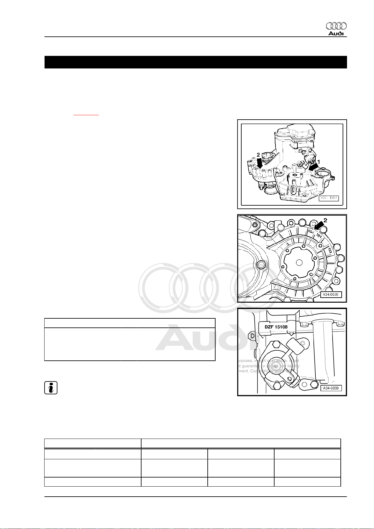
1.1 Location on gearbox
Code letters and date of manufacture -arrow 1-
Manual gearbox 02J -arrow 2-
Audi TT 1999 ➤
Manual gearbox 02J -arrow 2-
Code letters and date of manufacture of gearbox
Example: DZF 15 10 8
Additional data are production-related.
Note
I I I I
I I I I
Code letters Day Month Year -1998- of
manufacture
The gearbox code letters are also given on the vehicle data stick‐
ers.
1.2 Code letters, allocation, transmission ratios, capacities
Manual gearbox 5-speed 02J
Code letters
Manufactured from 06.98 09.00 09.00
Allocation Model Audi TT 1999 ▸ Audi TT 1999 ▸ Audi TT 1999 ▸
to 05.00 06.06 01.01
DZF
EGZ
1)
1. Gearbox identification 1
EVS
1)
Page 6
Protected by copyright. Copying for private or commercial purposes, in part or in whole, is not
permitted unless authorised by AUDI AG. AUDI AG does not guarantee or accept any liability
with respect to the correctness of information in this document. Copyright by AUDI AG.
Audi TT 1999 ➤
5-speed manual gearbox 02J - Edition 10.2007
Manual gearbox 5-speed 02J
Ratios:
Z2 : Z
1
Overall ratio i
in top gear 3.299 3.299 3.084
ov.
Engine 1.8 ltr. - 110 kW
1.8 ltr. - 132 kW
1.8 ltr. - 110 kW
1.8 ltr. - 132 kW
1.8 ltr. - 110 kW
Final drive 63 : 16 = 3.938 63 : 16 = 3.938 70 : 19 = 3.684
1st gear 33 : 10 = 3.300 33 : 10 = 3.300 33 : 10 = 3.300
2nd gear 35 : 18 = 1.944 35 : 18 = 1.944 35 : 18 = 1.944
3rd gear 34 : 26 = 1.308 34 : 26 = 1.308 34 : 26 = 1.308
4th gear 30 : 29 = 1.034 30 : 29 = 1.034 35 : 34 = 1.029
5th gear 31 : 37 = 0.838 31 : 37 = 0.838 36 : 43 = 0.837
6th gear - - Reverse gear 17 : 10 x 36 : 20 = 3.060 17 : 10 x 36 : 20 = 3.060 17 : 10 x 36 : 20 = 3.060
Speedometer 13 : 22 = 0.591 13 : 22 = 0.591 13 : 22 = 0.591
Capacity 2.0 litres
Clutch actuation Hydraulic
Drive shaft flange ∅ 108 mm 108 mm 108 mm
1)
As of 09.00, modified 1st gear synchromesh and modified selector mechanism on gearbox
• The following data can be found in the ⇒ Electronic parts catalogue .
♦ Gear oil specification
♦ Correct type of clutch plate and pressure plate
Manual gearbox 5-speed 02J
Code letters
EWV
1)
Manufactured from 05.00
to 09.00
Allocation Model Audi TT 1999 ▸
Ratios:
Z2 : Z
1
Overall ratio i
in top gear 3.299
ov.
Engine 1.8 ltr. - 132 kW
Final drive 63 : 16 = 3.938
1st gear 33 : 10 = 3.300
2nd gear 35 : 18 = 1.944
3rd gear 34 : 26 = 1.308
4th gear 30 : 29 = 1.034
5th gear 31 : 37 = 0.838
6th gear Reverse gear 17 : 10 x 36 : 20 = 3.060
Speedometer 13 : 22 = 0.591
Capacity 2.0 litres
Clutch actuation Hydraulic
Drive shaft flange ∅ 108 mm
2 Rep. Gr.00 - Technical data
Page 7

Protected by copyright. Copying for private or commercial purposes, in part or in whole, is not
permitted unless authorised by AUDI AG. AUDI AG does not guarantee or accept any liability
with respect to the correctness of information in this document. Copyright by AUDI AG.
5-speed manual gearbox 02J - Edition 10.2007
Manual gearbox 5-speed 02J
1)
As of 05.00, modified 1st gear synchromesh
• The following data can be found in the ⇒ Electronic parts catalogue .
♦ Gear oil specification
♦ Correct type of clutch plate and pressure plate
Audi TT 1999 ➤
1. Gearbox identification 3
Page 8
Protected by copyright. Copying for private or commercial purposes, in part or in whole, is not
permitted unless authorised by AUDI AG. AUDI AG does not guarantee or accept any liability
with respect to the correctness of information in this document. Copyright by AUDI AG.
Audi TT 1999 ➤
5-speed manual gearbox 02J - Edition 10.2007
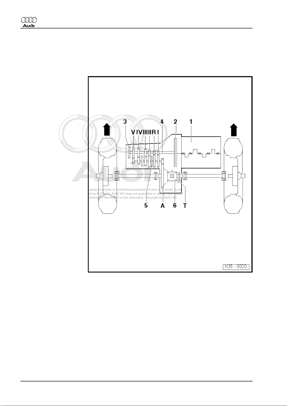
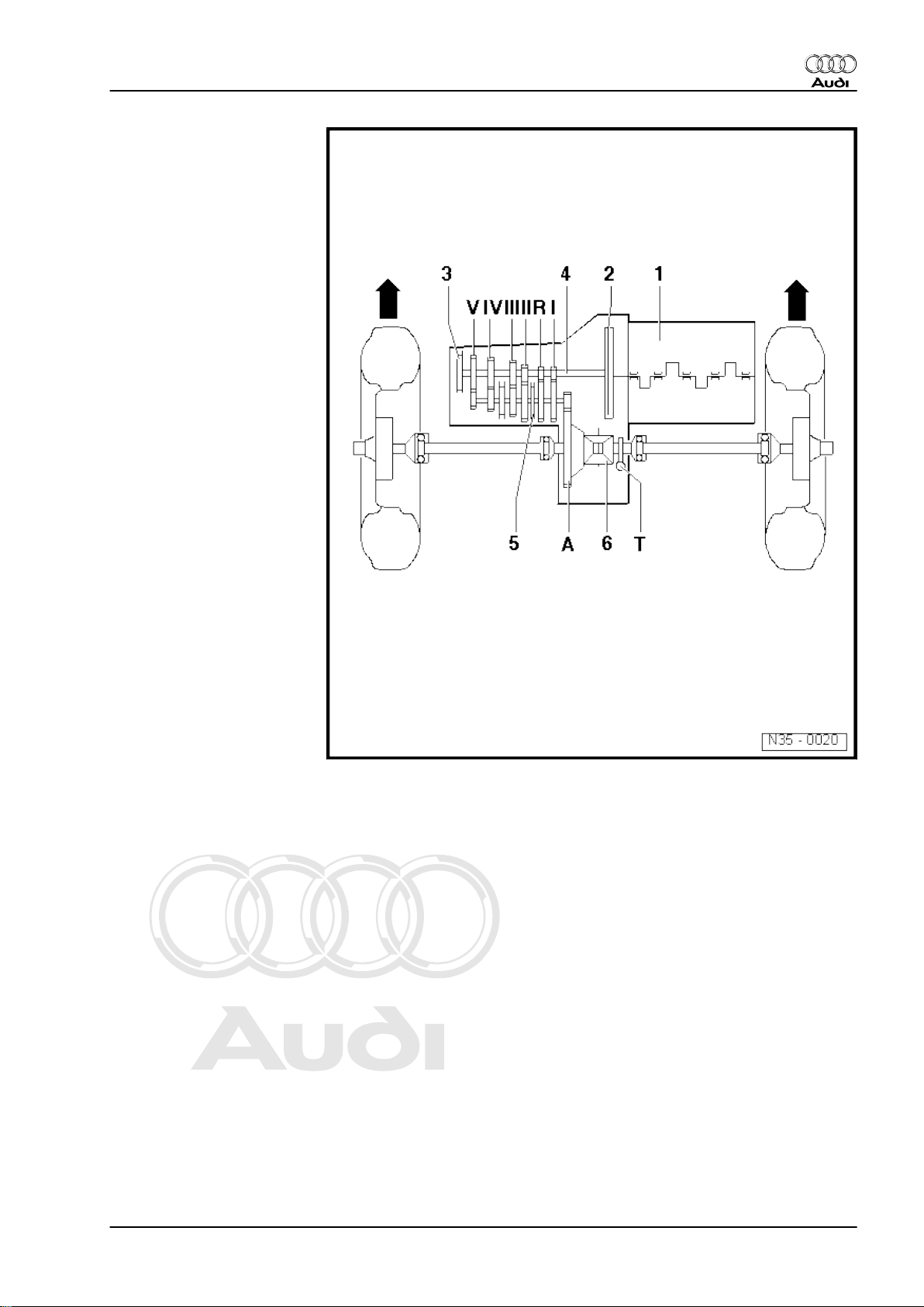
2 Transmission layout
Identification
-Arrows- point in direction of travel
1 - Engine
2 - Clutch
3 - Manual gearbox
4 - Input shaft
5 - Output shaft / pinion shaft
6 - Differential
Ratio
-Arrows- point in direction of travel
4 Rep. Gr.00 - Technical data
Page 9
Protected by copyright. Copying for private or commercial purposes, in part or in whole, is not
permitted unless authorised by AUDI AG. AUDI AG does not guarantee or accept any liability
with respect to the correctness of information in this document. Copyright by AUDI AG.
I - 1st gear
II - 2nd gear
III - 3rd gear
IV - 4th gear
V - 5th gear
R - Reverse gear
A - Final drive
T - Speedometer drive
Audi TT 1999 ➤
5-speed manual gearbox 02J - Edition 10.2007
2. Transmission layout 5
Page 10

Protected by copyright. Copying for private or commercial purposes, in part or in whole, is not
permitted unless authorised by AUDI AG. AUDI AG does not guarantee or accept any liability
with respect to the correctness of information in this document. Copyright by AUDI AG.
Audi TT 1999 ➤
5-speed manual gearbox 02J - Edition 10.2007
3 Calculating ratio “i”
Example:
5th gear Final drive
Drive gear ZG1 = 37 ZA1 = 16
Driven gear ZG2 = 31 ZA2 = 63
i = Z2 : Z1
1)
iG = gear ratio = ZG2 : ZG1 = 31 : 37 = 0.838
iA = axle ratio = ZA2 : ZA1 = 63 : 16 = 3.938
iov = overall ratio
iov = iG x iA = 0.838 x 3.938 = 3.299
1) Z1 = No. of teeth on drive gear, Z2 = No. of teeth on driven gear
6 Rep. Gr.00 - Technical data
Page 11
Protected by copyright. Copying for private or commercial purposes, in part or in whole, is not
permitted unless authorised by AUDI AG. AUDI AG does not guarantee or accept any liability
with respect to the correctness of information in this document. Copyright by AUDI AG.
5-speed manual gearbox 02J - Edition 10.2007
4 General repair instructions
Proper tools and the maximum possible care and cleanliness are
essential for satisfactory gearbox repairs. The usual basic safety
precautions also naturally apply when carrying out repair work.
A number of generally applicable instructions for the various re‐
pair procedures - which were previously repeated at numerous
places in the Workshop Manual - are summarised here. They ap‐
ply to the work described in this Manual.
Special tools
For a complete list of special tools used in this Workshop Manual
⇒ Workshop equipment and special tools catalogue .
Gearbox
♦ When installing, ensure that the dowel sleeves between the
engine and gearbox are correctly located.
♦ When installing a new gearbox, check the oil level and fill up
with oil if necessary ⇒ page 82 .
♦ Capacity ⇒ page 1 .
Audi TT 1999 ➤
Note
♦
If the oil level is topped up with the gearbox installed, check
oil level as follows:
♦
Fill with oil to bottom lip of filler hole and refit screw plug. Start
engine, engage a gear and allow gearbox to turn for approx.
2 minutes. Switch off engine and again top up oil to bottom lip
of filler hole.
Sealants
♦ Thoroughly clean joint surfaces on gearbox housing etc. be‐
fore applying sealant .
♦ Apply sealant -AMV 188 200 03- evenly and not too thickly.
O-rings, oil seals and gaskets
♦ Always renew O-rings, oil seals and gaskets.
♦ After removing gaskets and seals, always inspect the contact
surface on the housing or shaft for burrs resulting from removal
or for other signs of damage.
♦ Thoroughly clean housing joint surfaces before assembling.
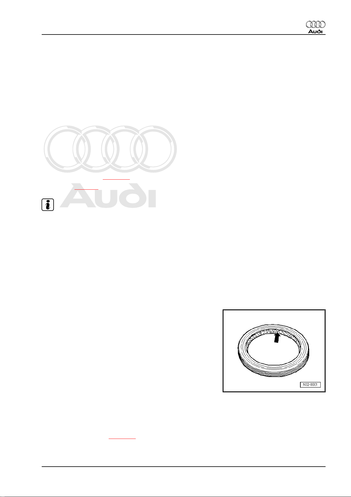
♦ Before installing oil seals, lightly oil the outer circumference of
the seal and fill the space between the sealing lips -arrowabout half full with grease -G 052 128 A1- .
♦ The open side of the oil seals faces toward the side with fluid
filling.
♦ When installing a new oil seal, position the seal in the housing
so that the sealing lip does not contact the shaft in the same
place as the old seal (make use of insertion depth tolerances).
♦ Lightly lubricate O-rings before installation to prevent them
from being trapped and damaged during assembly.
♦ After renewing seals and gaskets, check and, if necessary, top
up oil level in gearbox ⇒ page 82 .
Locking elements
4. General repair instructions 7
Page 12
Protected by copyright. Copying for private or commercial purposes, in part or in whole, is not
permitted unless authorised by AUDI AG. AUDI AG does not guarantee or accept any liability
with respect to the correctness of information in this document. Copyright by AUDI AG.
Audi TT 1999 ➤
5-speed manual gearbox 02J - Edition 10.2007
♦ Do not over-stretch circlips.
♦ Always renew circlips which have been damaged or over-
stretched.
♦ Circlips must be properly seated in the base of the groove.
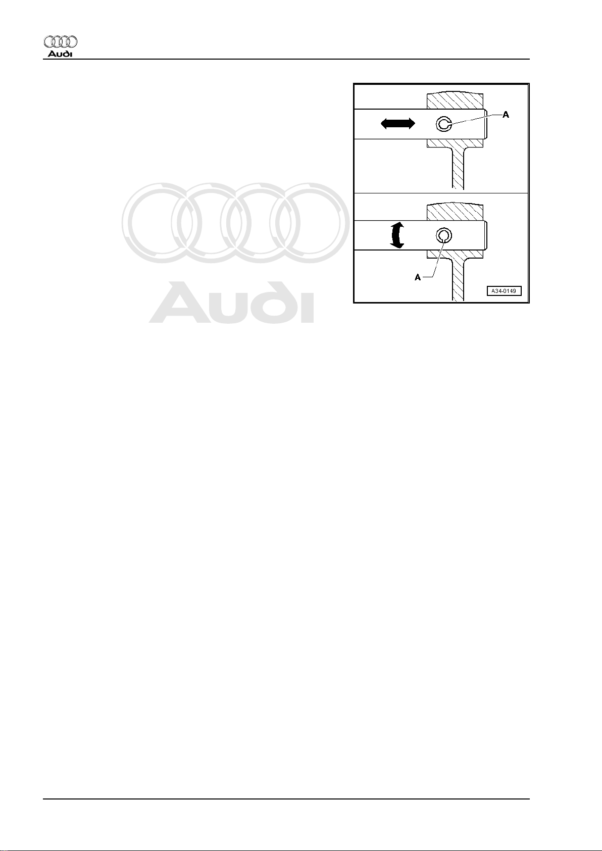
♦ Renew spring pins. Position: the slit -A- should be in line with
the line of force -arrow-.
Nuts, bolts
♦ Loosen the nuts and bolts in reverse sequence to the specified
tightening sequence.
♦ Nuts and bolts which secure covers and housings should be
loosened and tightened in diagonal sequence and in stages if
no tightening sequence is specified.
♦ Especially delicate parts, such as clutch pressure plates, must
not be distorted. Loosen and tighten bolts and nuts in stages
in diagonal sequence.
♦ The tightening torques stated apply to non-oiled nuts and
bolts.
♦ Always renew self-locking bolts and nuts.
♦ Use a wire brush to clean the threads of bolts which are se‐
cured with locking fluid. Then apply locking fluid AMV 185 101 A1- to bolt threads before installing.
♦ Threaded holes which take self-locking bolts or bolts coated
with locking fluid must be cleaned (using a tap or similar). Oth‐
erwise there is a danger of the bolts shearing off the next time
they are removed.
Bearings
♦ Install needle bearings so the lettering (side with thicker metal)
faces towards the installing tool.
♦ Install new tapered roller bearings as supplied; do not lubricate
additionally with oil.
♦ Lubricate all bearings (except new tapered roller bearings)
with gear oil before installing in gearbox.
♦ Always renew the tapered roller bearings on one shaft togeth‐
er and use new bearings from a single manufacturer.
♦ Use inductive heater -VAS 6414- to heat inner races to approx.
100°C before installing. Press home onto stop when installing
so there is no axial clearance.
♦ Do not interchange the outer or inner races of bearings of the
same size (the bearings are paired).
Shims
♦ Measure shims at several points with a micrometer. Tolerance
variations make it possible to obtain the exact shim thickness
required.
♦ Check for burrs and damage.
♦ Install only shims which are in perfect condition.
Synchro-rings
8 Rep. Gr.00 - Technical data
Page 13
Protected by copyright. Copying for private or commercial purposes, in part or in whole, is not
permitted unless authorised by AUDI AG. AUDI AG does not guarantee or accept any liability
with respect to the correctness of information in this document. Copyright by AUDI AG.
5-speed manual gearbox 02J - Edition 10.2007
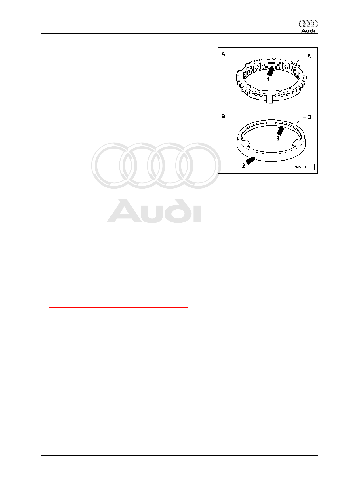
♦ Do not interchange. When re-using synchro-rings, always fit
to the same gear wheel.
♦ Check for wear; renew if necessary.
♦ Check the grooves -arrow 1- on synchro-ring -A- and on inner
ring for wear (flattened sections in grooves).
♦ Make sure that the coating of coated synchro-rings is not dam‐
aged.
♦ If an intermediate ring -B- is fitted, check the outer contact
surface -arrow 2- and inner contact surface -arrow 3- of the
intermediate ring for scoring and visible traces of wear.
♦ Check chamfer on selector gear for scoring and visible traces
of wear.
♦ Lubricate synchroniser rings with gear oil before installing.
Gear wheels
♦ Note correct installation position.
♦ Before installing, clean and heat to 100°C (maximum) using
inductive heater -VAS 6414- .
Selector gears
♦ After installing, check 1st to 5th selector gears for minimal axial
play and freedom of movement.
Clutch actuation
♦ When removing gearbox, remove clutch slave cylinder without
disconnecting pipes.
♦ Do not depress the clutch pedal after removing the slave cyl‐
inder if the hydraulic pipe is still connected. Otherwise, the
piston will be pressed out of the slave cylinder and be de‐
stroyed.
♦ Ensure that the pressure plate is kept straight: loosen and
tighten bolts in a diagonal sequence and in several gradual
stages.
♦ If the clutch pedal does not return to its initial position after
releasing it (clutch pedal in rest position), you must bleed the
clutch system (further measures
⇒ “1.1 Checking hydraulic clutch mechanism”, page 11 ).
♦ If the clutch has burnt out, thoroughly clean the bell housing,
flywheel and parts of the engine facing the gearbox in order to
prevent odours.
Audi TT 1999 ➤
4. General repair instructions 9
Page 14
Protected by copyright. Copying for private or commercial purposes, in part or in whole, is not
permitted unless authorised by AUDI AG. AUDI AG does not guarantee or accept any liability
with respect to the correctness of information in this document. Copyright by AUDI AG.
Audi TT 1999 ➤
5-speed manual gearbox 02J - Edition 10.2007
30 – Clutch
1 Servicing clutch mechanism
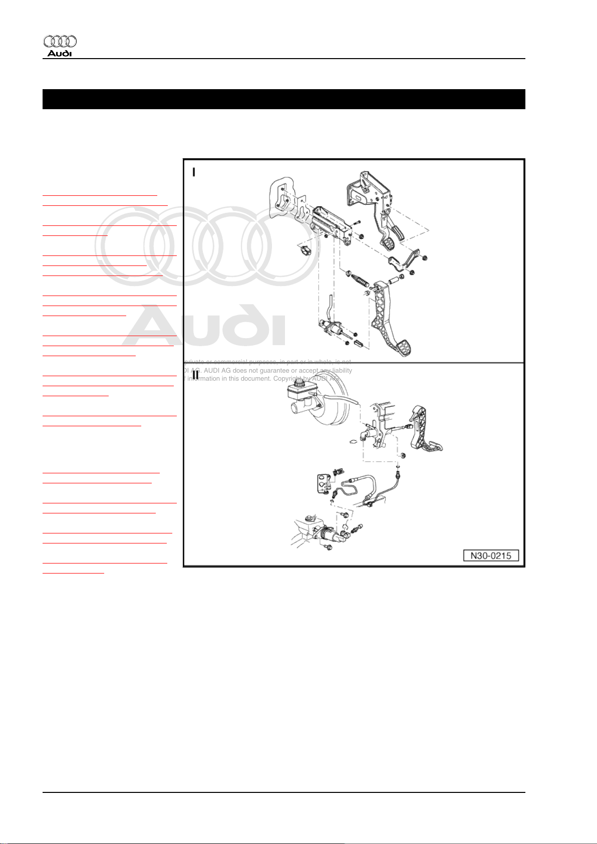
I - Exploded view - pedal clus‐
ter
⇒ “1.1 Checking hydraulic
clutch mechanism”, page 11
⇒ “1.2 Pedal cluster - exploded
view”, page 13
⇒ “1.3 Removing and installing
clutch pedal switch F36
(square housing)”, page 14
⇒ “1.4 Removing and installing
clutch pedal switch F36 (round
housing)”, page 14
⇒ “1.5 Removing and installing
clutch pedal switch for engine
start F194 ”, page 15
⇒ “1.6 Removing and installing
over-centre spring (LHD vehi‐
cles)”, page 16
⇒ “1.7 Removing and installing
clutch pedal”, page 17
II - Exploded view - hydraulic
system
⇒ “1.8 Exploded view - hy‐
draulic system”, page 19
⇒ “1.9 Removing and installing
master cylinder”, page 20
⇒ “1.10 Removing and instal‐
ling slave cylinder”, page 23
⇒ “1.11 Bleeding clutch sys‐
tem”, page 26
10 Rep. Gr.30 - Clutch
Page 15

Protected by copyright. Copying for private or commercial purposes, in part or in whole, is not
permitted unless authorised by AUDI AG. AUDI AG does not guarantee or accept any liability
with respect to the correctness of information in this document. Copyright by AUDI AG.
Note
♦
Before renewing the master or
slave cylinder on the assumption
that it is defective you must first
check the clutch mechanism
⇒ page 11 .
♦
Disconnect battery earth strap.
♦
Note radio coding for vehicles
with coded radio.
♦
Apply polycarbamide grease -G
052 142 A2- to all bearings and
contact surfaces.
♦
Make sure that no brake fluid es‐
capes into the footwell, the ple‐
num chamber or onto the gear‐
box below. If this does happen,
clean the affected area thor‐
oughly.
♦
When performing work in the
footwell, put cloths on the carpet
to protect it from possible brake
fluid spills.
Audi TT 1999 ➤
5-speed manual gearbox 02J - Edition 10.2007
1.1 Checking hydraulic clutch mechanism
• Make sure the pedal returns to its initial position and is not
obstructed by additional floor mats or mats that have slipped
out of position.
• Bleed the clutch system if necessary.
1. Servicing clutch mechanism 11
Page 16
Protected by copyright. Copying for private or commercial purposes, in part or in whole, is not
permitted unless authorised by AUDI AG. AUDI AG does not guarantee or accept any liability
with respect to the correctness of information in this document. Copyright by AUDI AG.
Audi TT 1999 ➤
5-speed manual gearbox 02J - Edition 10.2007
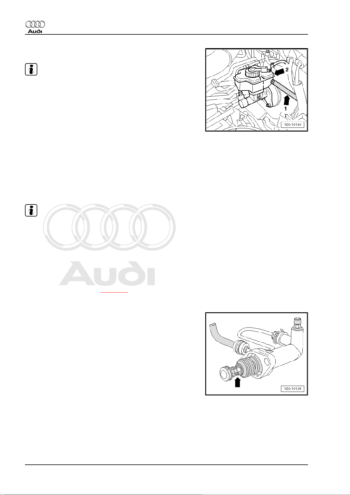
– First check brake fluid level in brake fluid reservoir.
Note
♦
The clutch hydraulics are connected to one of the chambers
-arrow 2- of the brake fluid reservoir via the supply hose
-arrow 1-.
♦
If this chamber is empty or contains too little brake fluid, the
system may be leaking.
– Then check the following components of the hydraulic clutch
mechanism for external leaks:
♦ Supply hose between brake fluid reservoir and master cylinder
♦ Master cylinder
♦ Pipe/hose assembly between master cylinder and slave cyl‐
inder
♦ Connections (plug-in connectors and threaded connections),
including hidden connections
♦ Slave cylinder
Note
♦
External leaks can be detected, for instance, by traces of brake
fluid on or below the gearbox as well as on the noise insulation
panel below the gearbox.
♦
Check correct routing of pipe/hose assembly between master
cylinder and slave cylinder. The pipe/hose assembly must not
be kinked or become trapped.
– Then depress clutch pedal carefully; hold pedal in five different
positions for approx. 20 seconds at each position over its full
travel. Have a 2nd person check the components of the hy‐
draulic clutch mechanism ⇒ page 12 for visible leaks. At the
same time the 1st person should check whether the clutch
pedal yields under the foot at any of the held positions.
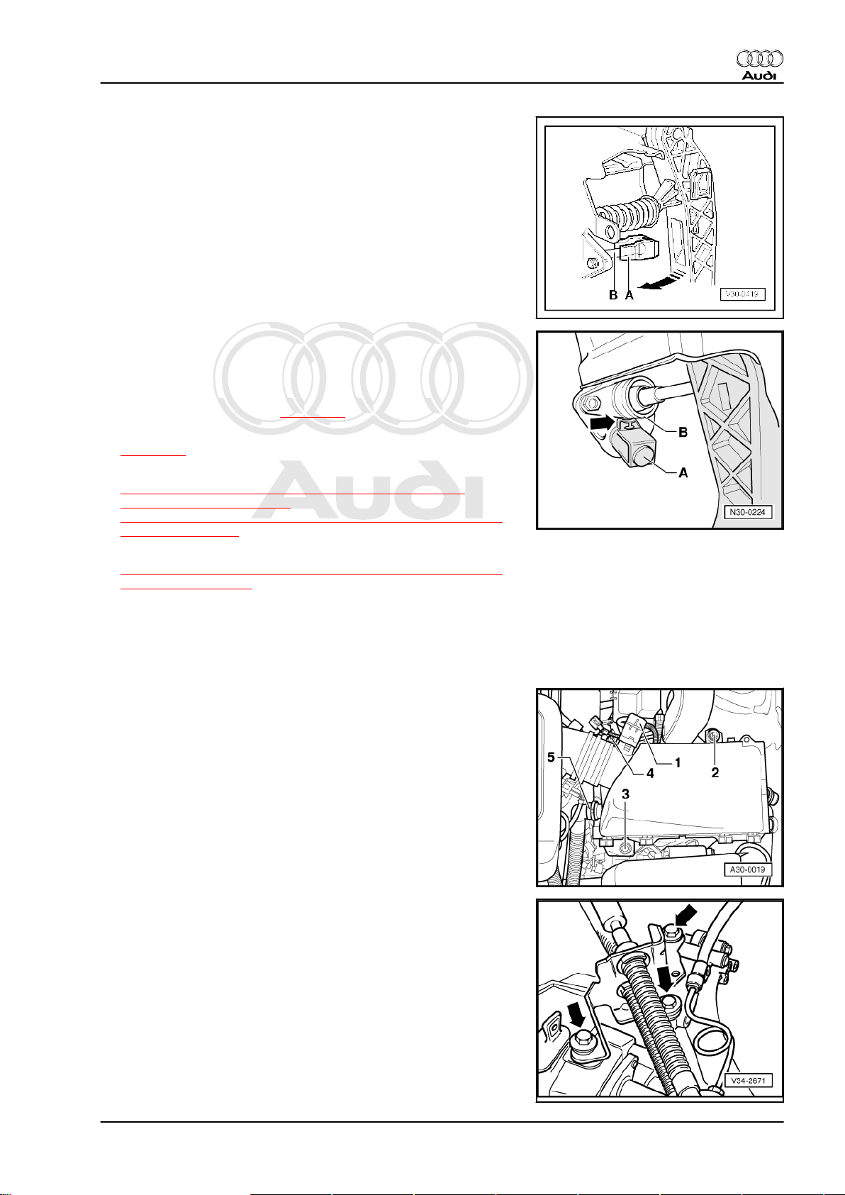
– Finally, detach slave cylinder from gearbox (do not open pipe
connections) and check sleeve for traces of escaped brake
fluid.
– Detach sleeve from plunger -arrow- to check for leaks.
12 Rep. Gr.30 - Clutch
Page 17
Protected by copyright. Copying for private or commercial purposes, in part or in whole, is not
permitted unless authorised by AUDI AG. AUDI AG does not guarantee or accept any liability
with respect to the correctness of information in this document. Copyright by AUDI AG.
5-speed manual gearbox 02J - Edition 10.2007
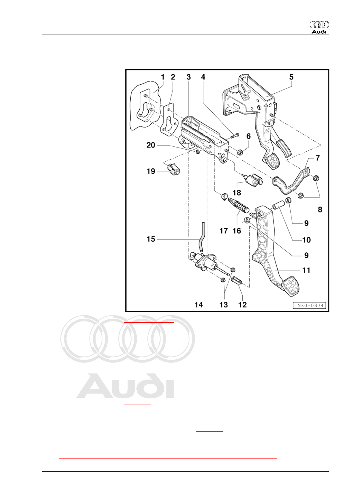
1.2 Pedal cluster - exploded view
1 - Bulkhead
❑ With mounting for
mounting bracket and
master cylinder
2 - Gasket
❑ Always renew
3 - Mounting bracket
❑ For mounting clutch
pedal
4 - Bolt
5 - Mounting bracket
❑ For mounting accelera‐
tor pedal and brake ped‐
al
6 - Nut
❑ 25 Nm
❑ Self-locking
❑ Always renew
7 - Connecting plate
8 - Nut
❑ 25 Nm
❑ Self-locking
❑ Always renew
9 - Bearing bush
10 - Pivot pin
11 - Clutch pedal
❑ Removing and installing
⇒ page 17
12 - Retaining clip
❑ Removing and installing ⇒ Item 4 (page 19)
13 - Nut
❑ 25 Nm
❑ Self-locking
❑ Always renew
14 - Master cylinder
❑ Removing and installing ⇒ page 20
15 - Supply hose
16 - Over-centre spring
❑ Removing and installing ⇒ page 16
17 - Over-centre spring mounting
❑ Install in mounting bracket
❑ When renewing, remove and install master cylinder ⇒ page 20
18 - Clutch pedal switch -F36- or clutch pedal switch for engine start -F194-
❑ Clutch pedal switch for engine start -F194- only installed on USA models
❑ ⇒ “1.3 Removing and installing clutch pedal switch F36 (square housing)”, page 14
Audi TT 1999 ➤
1. Servicing clutch mechanism 13
Page 18
Protected by copyright. Copying for private or commercial purposes, in part or in whole, is not
permitted unless authorised by AUDI AG. AUDI AG does not guarantee or accept any liability
with respect to the correctness of information in this document. Copyright by AUDI AG.
Audi TT 1999 ➤
5-speed manual gearbox 02J - Edition 10.2007
❑ ⇒ “1.4 Removing and installing clutch pedal switch F36 (round housing)”, page 14
❑ ⇒ “1.5 Removing and installing clutch pedal switch for engine start F194 ”, page 15
19 - Stop
❑ For clutch pedal
❑ Installation position ⇒ page 22
20 - Nut
❑ 25 Nm
❑ Self-locking
❑ Always renew
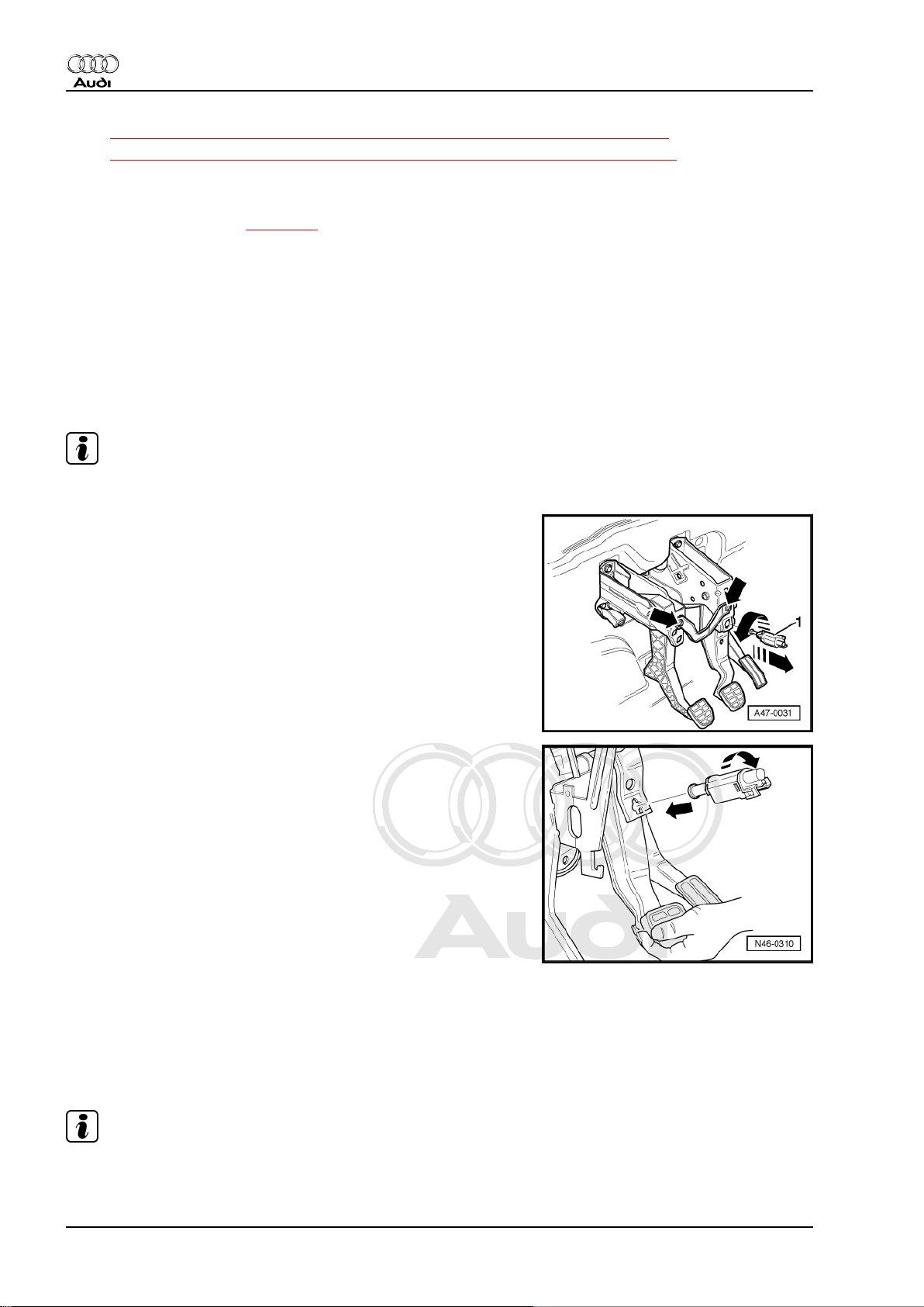
1.3 Removing and installing clutch pedal switch -F36- (square housing)
Note
To ensure a secure fit, the switch may only be fitted once.
Removing
– Remove storage compartment on driver's side ⇒ General
body repairs, interior; Rep. Gr. 68 .
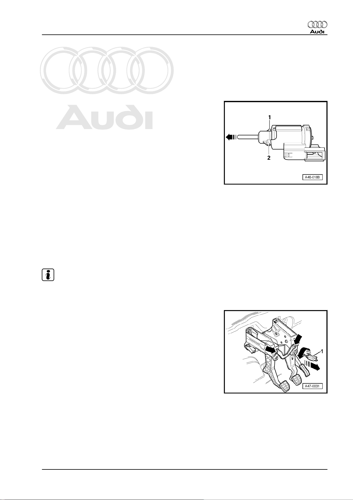
– Unplug electrical connector from clutch pedal switch.
– Remove clutch pedal switch -1- by turning 90° anti-clockwise.
Installing
Installation is carried out in reverse sequence; note the following:
– Grease plunger head of clutch pedal switch -F36- with poly‐
carbamide grease -G 052 142 A2- .
– Pull operating rod of clutch pedal switch all the way out.
– Push clutch pedal down by hand.
– Insert switch in mounting hole and secure by turning clockwise
through 90° -arrows-.
– Release clutch pedal
– Attach electrical connector to clutch pedal switch.
– Install storage compartment on driver's side ⇒ General body
repairs, interior; Rep. Gr. 68 .
1.4 Removing and installing clutch pedal switch -F36- (round housing)
Note
Clutch pedal switch may only be fitted once so as to ensure a firm
fit.
14 Rep. Gr.30 - Clutch
Page 19
Protected by copyright. Copying for private or commercial purposes, in part or in whole, is not
permitted unless authorised by AUDI AG. AUDI AG does not guarantee or accept any liability
with respect to the correctness of information in this document. Copyright by AUDI AG.
5-speed manual gearbox 02J - Edition 10.2007
Removing
– Remove storage compartment on driver's side ⇒ General
body repairs, interior; Rep. Gr. 68 .
– Unplug electrical connector from clutch pedal switch.
– Remove clutch pedal switch by turning anti-clockwise through
45°.
Installing
Installation is carried out in reverse sequence; note the following:
– Grease plunger head of clutch pedal switch -F36- with poly‐
carbamide grease -G 052 142 A2- .
– Pull out operating rod -arrow- all the way before installing
clutch pedal switch.
– Insert retainer tabs -1- and -2- of switch in recesses provided
in mounting hole and secure by turning clockwise through 45°.
• The clutch pedal should be in the normal position (i.e. not
pressed down).
• Do not press clutch pedal when installing.
• Plunger is adjusted automatically when clutch pedal switch is
installed.
– Attach electrical connector to clutch pedal switch.
– Install storage compartment on driver's side ⇒ General body
repairs, interior; Rep. Gr. 68 .
1.5 Removing and installing clutch pedal
switch for engine start -F194-
Audi TT 1999 ➤
Note
♦
Only fitted on USA models
♦
To ensure a secure fit, the switch may only be fitted once.
Removing
– Remove storage compartment on driver's side ⇒ General
body repairs, interior; Rep. Gr. 68 .
1. Servicing clutch mechanism 15
Page 20
Protected by copyright. Copying for private or commercial purposes, in part or in whole, is not
permitted unless authorised by AUDI AG. AUDI AG does not guarantee or accept any liability
with respect to the correctness of information in this document. Copyright by AUDI AG.
Audi TT 1999 ➤
5-speed manual gearbox 02J - Edition 10.2007
– Detach electrical connector -1- on clutch pedal switch.
– Remove clutch pedal switch for engine start -F194- -2- by
turning 90° anti-clockwise in direction of -arrow-.
Installing
Installation is carried out in reverse sequence; note the following:
– Grease plunger head of clutch pedal switch for engine start -
F194- with polycarbamide grease -G 052 142 A2- .
– Pull operating rod of clutch pedal switch all the way out.
– Insert switch in mounting hole and secure by turning clockwise
through 90°.
– Clutch pedal fully depressed.
– Release clutch pedal
– Attach electrical connector to clutch pedal switch.
– Install storage compartment on driver's side ⇒ General body
repairs, interior; Rep. Gr. 68 .
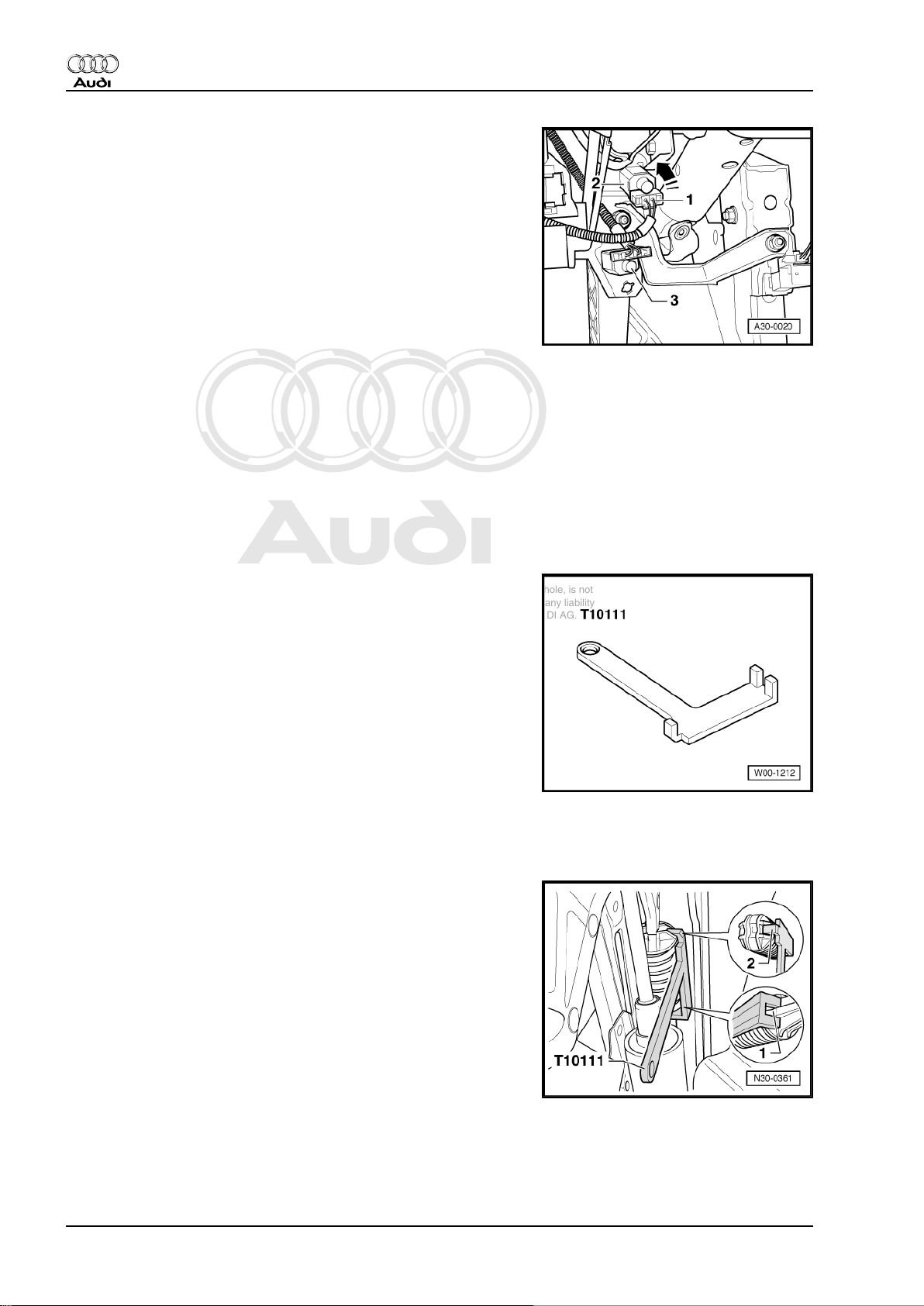
1.6 Removing and installing over-centre spring (LHD vehicles)
Special tools and workshop equipment required
♦ Assembly clip -T10111-
Removing
– Remove driver's storage compartment (bottom) ⇒ Rep. Gr.
68 .
– Fit assembly clip -T10111- from the right onto over-centre
spring.
– Ensure that the assembly clip is correctly seated:
1 - The rear part of assembly clip must be positioned on the overcentre spring so that the claws fit exactly over the rib -1-.
2 - Lightly depress clutch pedal towards bulkhead.
– Engage the lug -2- of the assembly clip into the cut-out on the
over-centre spring.
– Now depress the clutch pedal towards the bulkhead until the
over-centre spring can be removed from below from the
mountings on the mounting bracket and clutch pedal.
– Return clutch pedal to normal position.
16 Rep. Gr.30 - Clutch
Page 21
Protected by copyright. Copying for private or commercial purposes, in part or in whole, is not
permitted unless authorised by AUDI AG. AUDI AG does not guarantee or accept any liability
with respect to the correctness of information in this document. Copyright by AUDI AG.
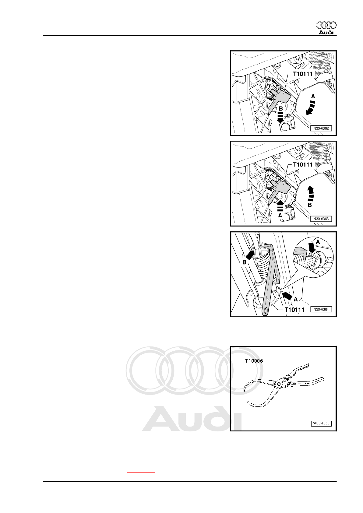
5-speed manual gearbox 02J - Edition 10.2007
– Turn over-centre spring together with assembly clip -T10111-
in direction of -arrow A- and take out downwards in direction
of -arrow B-.
Installing
– Pull clutch pedal into the passenger compartment.
– Insert over-centre spring together with assembly clip -T10111-
upwards (in direction of -arrow A-) into mounting bracket and
then turn in direction of -arrow B-.
Audi TT 1999 ➤
– Insert over-centre spring into rear mounting first -arrow A-.
– Operate clutch pedal until over-centre spring seats on mount‐
ing lug -arrow B- on clutch pedal.
– Return clutch pedal to normal position and remove assembly
clip.
– Install driver's storage compartment (bottom) ⇒ Rep. Gr. 68 .
1.7 Removing and installing clutch pedal
Special tools and workshop equipment required
♦ Pliers -T10005-
Removing
– If fitted, turn clutch pedal switch -F36- 45° anti-clockwise and
pull out of mounting.
– Remove over-centre spring ⇒ page 16 .
1. Servicing clutch mechanism 17
Page 22
Protected by copyright. Copying for private or commercial purposes, in part or in whole, is not
permitted unless authorised by AUDI AG. AUDI AG does not guarantee or accept any liability
with respect to the correctness of information in this document. Copyright by AUDI AG.
Audi TT 1999 ➤
5-speed manual gearbox 02J - Edition 10.2007
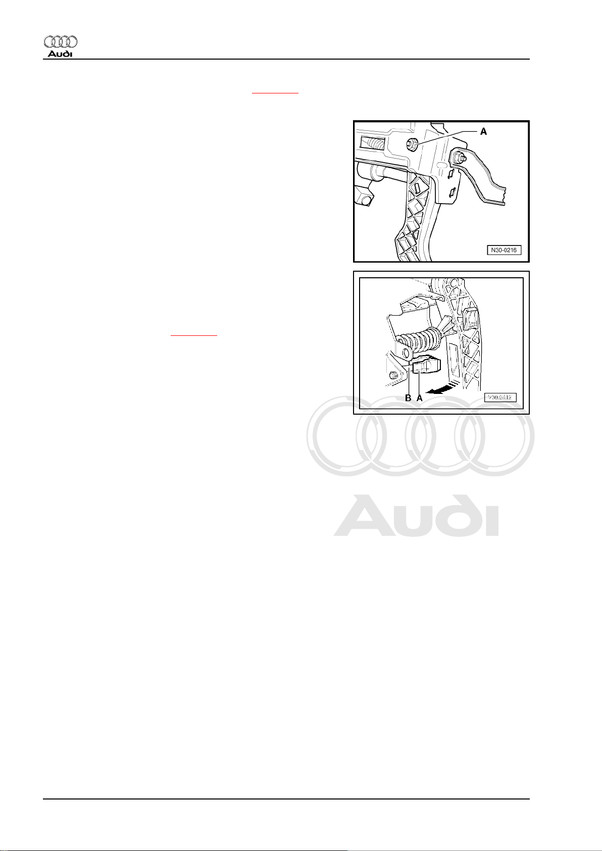
– Separate clutch pedal from master cylinder ⇒ page 22 and
push operating rod towards engine compartment as far as
stop.
– Remove nut -A-.
– Pull out bolt until clutch pedal can be removed.
Installing
Installation is carried out in reverse sequence; note the following:
– The retaining clip -A- must be fitted to the master cylinder op‐
erating rod -B-.
– Press clutch pedal in -direction of arrow- until it engages. En‐
sure that it is properly locked.
– Install over-centre spring ⇒ page 16 .
– If fitted, insert clutch pedal switch -F36- in mounting hole and
secure by turning 45° clockwise. Clutch pedal must be pressed
down.
18 Rep. Gr.30 - Clutch
Page 23
Protected by copyright. Copying for private or commercial purposes, in part or in whole, is not
permitted unless authorised by AUDI AG. AUDI AG does not guarantee or accept any liability
with respect to the correctness of information in this document. Copyright by AUDI AG.
5-speed manual gearbox 02J - Edition 10.2007
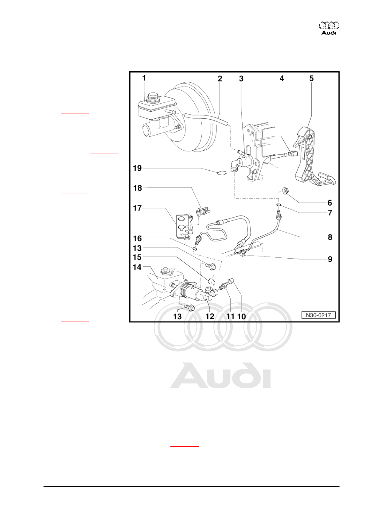
1.8 Exploded view - hydraulic system
1 - Brake fluid reservoir
2 - Supply hose
3 - Master cylinder
❑ Removing and installing
⇒ page 20
4 - Retaining clip
❑ Renew only when mas‐
ter cylinder has been re‐
moved
❑ Removing ⇒ page 20
❑ Pressing on
⇒ page 20
5 - Clutch pedal
❑ Removing and installing
⇒ page 17
6 - Nut
❑ 25 Nm
❑ Self-locking
❑ Always renew
7 - O-ring
❑ Push onto pipe connec‐
tion
❑ Lubricate with brake flu‐
id before installing
8 - Pipe/hose assembly
❑ Disconnecting from
master cylinder and in‐
stalling ⇒ page 21
❑ Disconnecting from
slave cylinder
⇒ page 24
❑ Allocate according to ⇒ Electronic parts catalogue
9 - Retainer
❑ Secured on body
10 - Dust cap
11 - Bleeder valve
❑ Bleeding clutch system ⇒ page 26
12 - Slave cylinder
❑ Removing and installing ⇒ page 23
13 - Bolt
❑ 23 Nm
14 - Gearbox
15 - Retaining clip
❑ Pull out retaining clip to disconnect pipe ⇒ page 21
16 - O-ring
❑ Push onto pipe connection
❑ Lubricate with brake fluid before installing
Audi TT 1999 ➤
1. Servicing clutch mechanism 19
Page 24
Protected by copyright. Copying for private or commercial purposes, in part or in whole, is not
permitted unless authorised by AUDI AG. AUDI AG does not guarantee or accept any liability
with respect to the correctness of information in this document. Copyright by AUDI AG.
Audi TT 1999 ➤
5-speed manual gearbox 02J - Edition 10.2007
17 - Support bracket
18 - Retainer
❑ Secure to support bracket for selector cables
19 - Retaining clip
❑ Pull out retaining clip to disconnect pipe ⇒ page 21
Levering retaining clip -A- off in direction of arrow
Pressing master cylinder operating rod into retaining clip -A- (in
direction of arrow).
1.9 Removing and installing master cylinder
Special tools and workshop equipment required
♦ Pliers -T10005-
20 Rep. Gr.30 - Clutch
Page 25
Protected by copyright. Copying for private or commercial purposes, in part or in whole, is not
permitted unless authorised by AUDI AG. AUDI AG does not guarantee or accept any liability
with respect to the correctness of information in this document. Copyright by AUDI AG.
5-speed manual gearbox 02J - Edition 10.2007
Removing
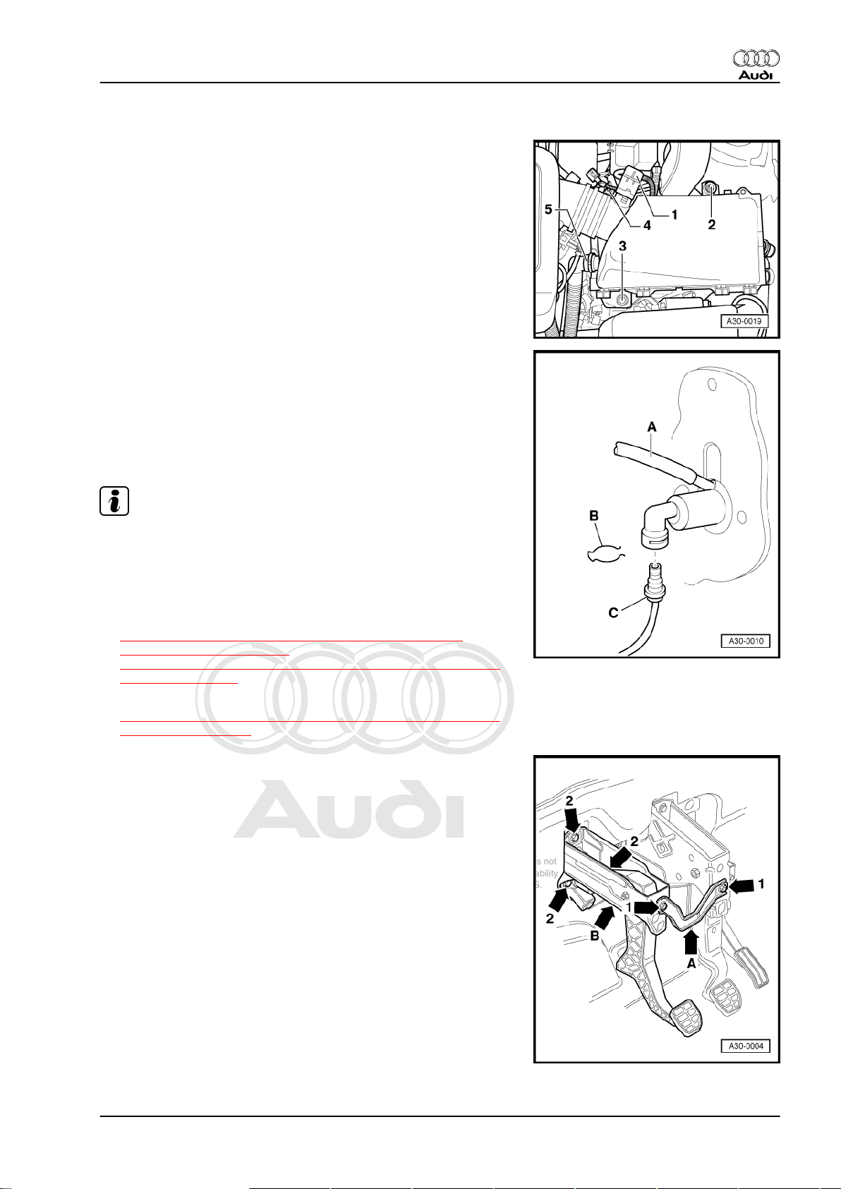
– Release hose clip -4- and detach intake hose and connector
-1- from air mass meter.
– Remove bolts -2- and -3-.
– If fitted, detach secondary air pipe -5- from air cleaner housing.
– Then remove complete air cleaner housing.
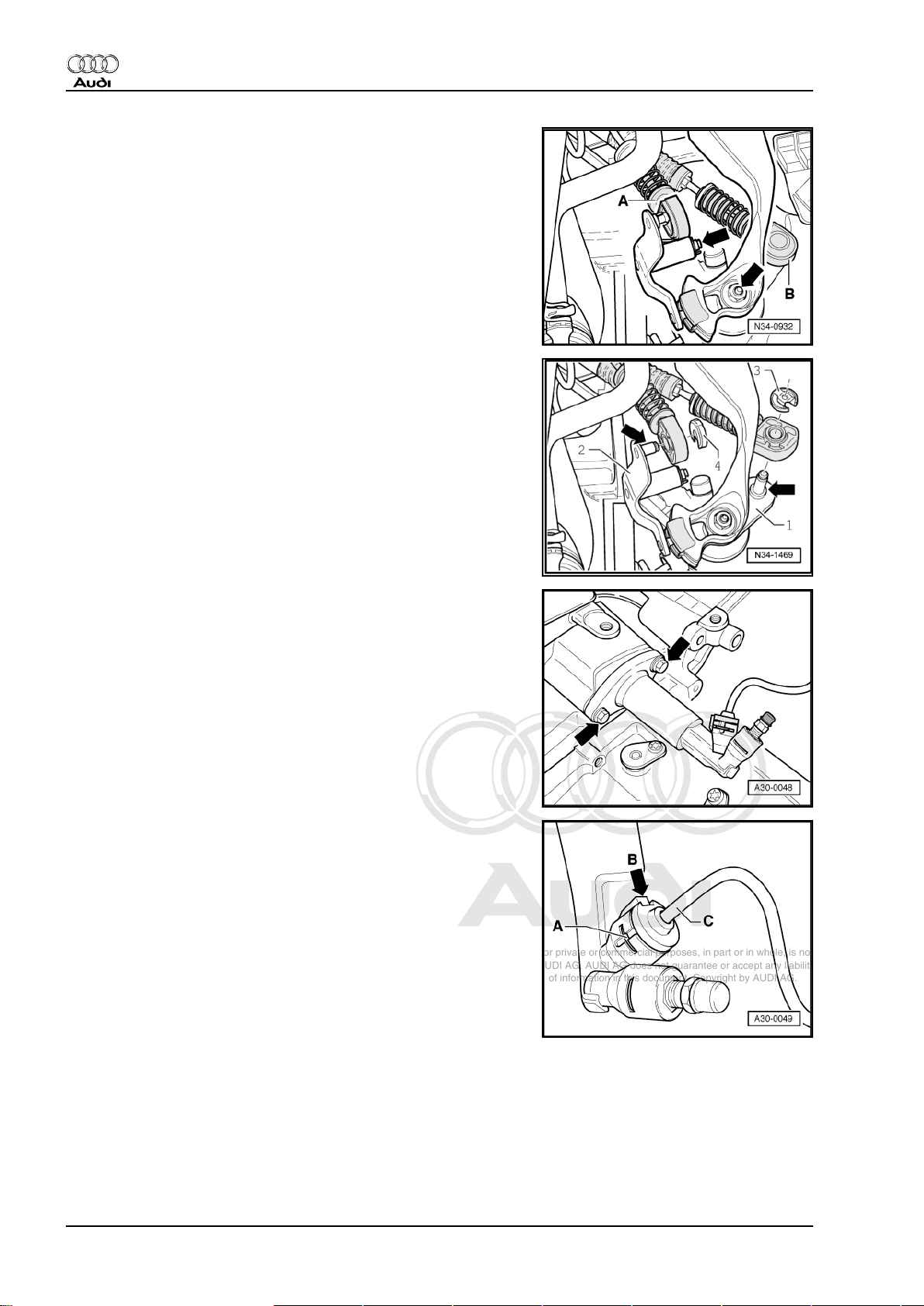
– Clamp off supply hose -A- coming from brake fluid reservoir
using hose clamp -3094- .
– Disconnect supply hose -A- at master cylinder.
– Remove retaining clip -B- from master cylinder.
– Pull pipe/hose assembly -C- out of master cylinder and seal
end of pipe.
Audi TT 1999 ➤
Note
In order to take out the master cylinder the entire clutch pedal
assembly must be removed.
– Remove driver's storage compartment (bottom) ⇒ Rep. Gr.
68 .
– If fitted, remove clutch pedal switch -F36-
⇒ “1.3 Removing and installing clutch pedal switch F36
(square housing)”, page 14 or
⇒ “1.4 Removing and installing clutch pedal switch F36 (round
housing)”, page 14 .
– If fitted, remove clutch pedal switch for engine start -F194- or
⇒ “1.5 Removing and installing clutch pedal switch for engine
start F194 ”, page 15 .
– Now remove complete clutch pedal mounting bracket as fol‐
lows:
– First remove connecting plate -arrow A- -arrows 1-.
– Then remove securing nuts -arrows 2- for mounting bracket
-arrow B-.
– Take off mounting bracket.
1. Servicing clutch mechanism 21
Page 26
Protected by copyright. Copying for private or commercial purposes, in part or in whole, is not
permitted unless authorised by AUDI AG. AUDI AG does not guarantee or accept any liability
with respect to the correctness of information in this document. Copyright by AUDI AG.
Audi TT 1999 ➤
5-speed manual gearbox 02J - Edition 10.2007
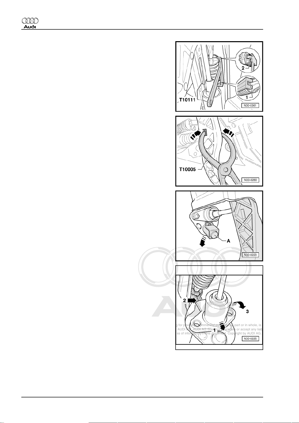
– Remove over-centre spring using assembly clip -T10111- as
follows:
1 - The rear part of assembly clip must be positioned on the overcentre spring so that the claws fit exactly over the rib -1-.
2 - Lightly depress clutch pedal towards clutch pedal stop.
– Engage the lug -2- of the assembly clip into the cut-out on the
over-centre spring.
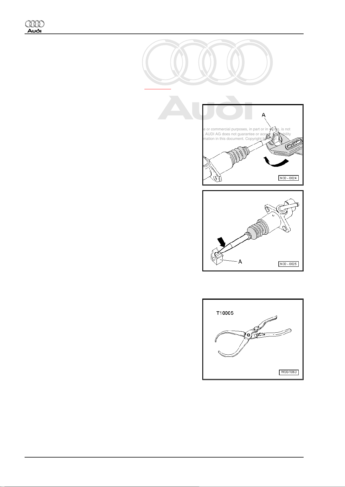
Release master cylinder operating rod from clutch pedal as fol‐
lows:
– Carefully pull clutch pedal towards you. At the same time,
press both sides of retaining clip inwards using pliers -T10005-
-arrows.
– Turn stop -A- for clutch pedal in direction of arrow and remove.
– Then push master cylinder in the direction of -arrow 1- onto
stop.
It must not be covered in upper area by over-centre spring mount‐
ing -arrow 2-.
– Then swing master cylinder in direction of -arrow 3- out of
mounting bracket.
Installing
Installation is carried out in reverse sequence; note the following:
22 Rep. Gr.30 - Clutch
Page 27
Protected by copyright. Copying for private or commercial purposes, in part or in whole, is not
permitted unless authorised by AUDI AG. AUDI AG does not guarantee or accept any liability
with respect to the correctness of information in this document. Copyright by AUDI AG.
5-speed manual gearbox 02J - Edition 10.2007
– Retaining clip -A- must be fitted on operating rod -B- of master
cylinder.
– Press clutch pedal in -direction of arrow- until it engages. En‐
sure that it is properly locked.
– Fit stop -A- for clutch pedal again.
Installation position:
The arm -arrow- points towards master cylinder -B-.
– Install over-centre spring ⇒ page 16 .
– Bleed clutch system after installing master cylinder
⇒ page 26 .
– If fitted, install clutch pedal switch -F36-
⇒ “1.3 Removing and installing clutch pedal switch F36
(square housing)”, page 14 or
⇒ “1.4 Removing and installing clutch pedal switch F36 (round
housing)”, page 14 .
– If fitted, install clutch pedal switch for engine start -F194- or
⇒ “1.5 Removing and installing clutch pedal switch for engine
start F194 ”, page 15 .
– Install complete air cleaner housing ⇒ Rep. Gr. 24 .
Audi TT 1999 ➤
1.10 Removing and installing slave cylinder
Removing
– Release hose clip -4- and detach intake hose and connector
-1- from air mass meter.
– Remove bolts -2- and -3-.
– If fitted, detach secondary air pipe -5- from air cleaner housing.
– Then remove complete air cleaner housing.
– Detach cable support bracket from gearbox -arrows- and un‐
clip pipe/hose assembly.
1. Servicing clutch mechanism 23
Page 28
Protected by copyright. Copying for private or commercial purposes, in part or in whole, is not
permitted unless authorised by AUDI AG. AUDI AG does not guarantee or accept any liability
with respect to the correctness of information in this document. Copyright by AUDI AG.
Audi TT 1999 ➤
5-speed manual gearbox 02J - Edition 10.2007
Detaching selector mechanism on vehicles up to 06.01
– Remove circlip -arrow- and pull off gate selector cable -A- with
relay lever.
– Remove nut -arrow- and detach gear selector cable -B- with
gearbox selector lever.
– Tie up gear selector cable with gearbox selector lever and gate
selector cable with relay lever.
Detaching selector mechanism on vehicles from 07.01
– Detach circlip -3- for gear selector cable from gearbox selector
lever -1-.
– Detach circlip -4- for gate selector cable from relay lever -2-.
– Pull gate selector cable and gear selector cable off joint pins
-arrows-.
Continued for all vehicles
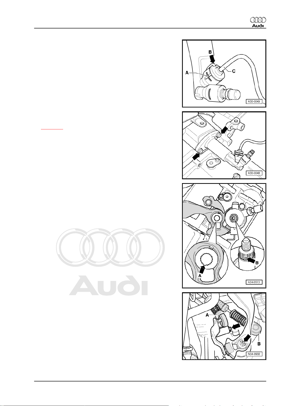
– Remove bolts -arrows- for slave cylinder.
– Remove slave cylinder.
– Pull out clip -A- and then pull pipe/hose assembly -C- out of
slave cylinder and seal end of pipe.
Installing
Installation is carried out in reverse sequence; note the following:
24 Rep. Gr.30 - Clutch
Page 29
Protected by copyright. Copying for private or commercial purposes, in part or in whole, is not
permitted unless authorised by AUDI AG. AUDI AG does not guarantee or accept any liability
with respect to the correctness of information in this document. Copyright by AUDI AG.
5-speed manual gearbox 02J - Edition 10.2007
– Press retaining clip -A- in as far as it will go.
– Position recess on hose/pipe assembly so that it faces lug on
clutch slave cylinder -arrow B-.
– Insert hose/pipe assembly -C- in slave cylinder, making sure
you hear it engage.
– Lubricate end of operating rod with MoS2 grease.
– Install slave cylinder -arrows-.
– After installing slave cylinder, bleed clutch system
⇒ page 26 .
Attaching selector mechanism on vehicles up to 06.01
Audi TT 1999 ➤
Fit gearbox selector lever as follows:
– When installing gearbox selector lever, make sure that the gap
in the splines -arrow A- aligns with the wider spline -arrow Bon the selector shaft.
– Fit gear selector cable -B- with gearbox selector lever
-arrow-.
– Fit gate selector cable -A- with relay lever and secure
-arrow-.
Attaching selector mechanism on vehicles from 07.01
Cable end-pieces securing cables to gearbox selector lever and
relay lever have open drillings.
The holes in the cable end-pieces have different diameters.
1. Servicing clutch mechanism 25
Page 30
Protected by copyright. Copying for private or commercial purposes, in part or in whole, is not
permitted unless authorised by AUDI AG. AUDI AG does not guarantee or accept any liability
with respect to the correctness of information in this document. Copyright by AUDI AG.
Audi TT 1999 ➤
5-speed manual gearbox 02J - Edition 10.2007
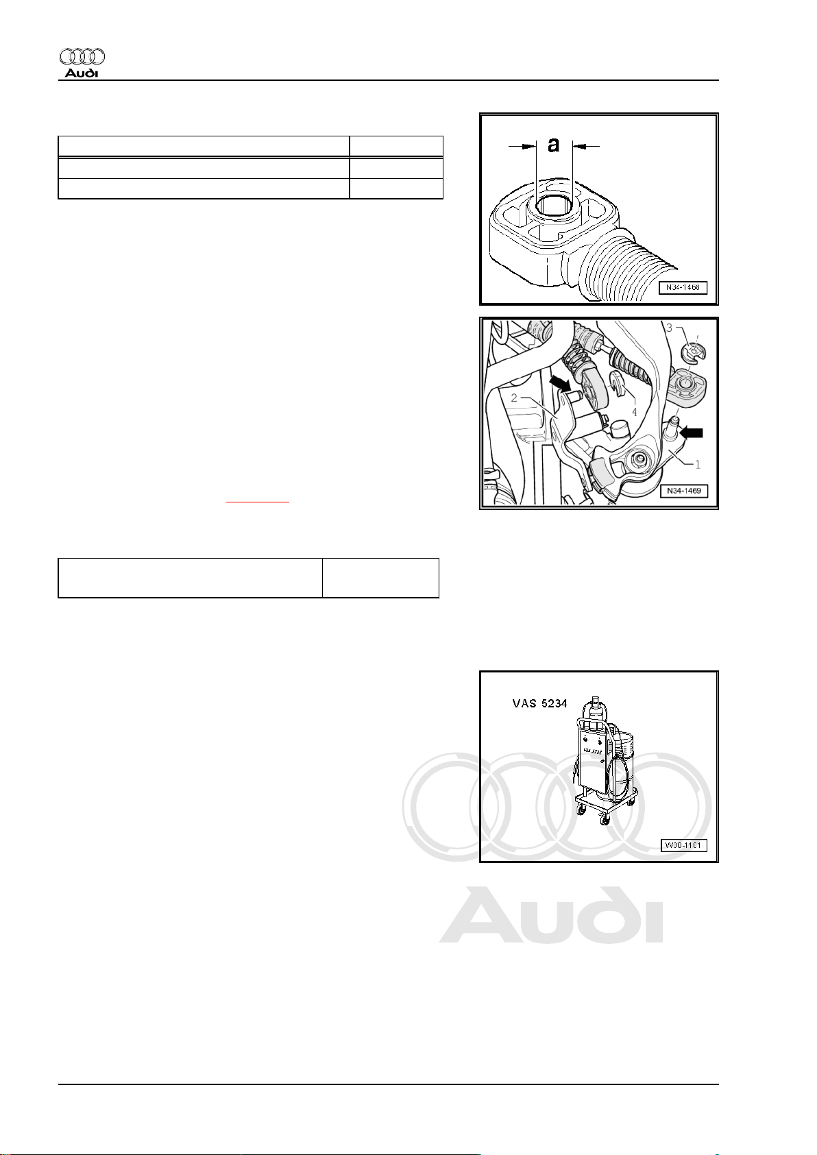
Allocation
Cable end-piece for: Distance “a”
Gear selector cable to gearbox selector lever 10 mm
Gate selector cable to relay lever 8 mm
– Spread small amount of polycarbamide grease -G 052 142 A2-
onto pins -arrows- of gearbox selector lever -1- and relay lever
-2-.
– Always renew circlips -3- and -4- after removing.
– Secure gear selector cable with circlip -3- and gate selector
cable with circlip -4-.
Continued for all selector mechanisms:
– Install cable support bracket on gearbox (arrows), if necessary
clip pipe/hose assembly onto cable support bracket.
Adjust selector mechanism ⇒ page 51 .
– Install complete air cleaner housing ⇒ Rep. Gr. 24 .
Tightening torques
Clutch slave cylinder to gearbox 23 Nm
Selector cable support bracket to gearbox 25 Nm
1.11 Bleeding clutch system
Special tools and workshop equipment required
♦ Brake filling and bleeding equipment -VAS 5234- or brake fill‐
ing and bleeding equipment -V.A.G 1869-
♦ Brake fluid specification ⇒ Rep. Gr. 47 .
26 Rep. Gr.30 - Clutch
Page 31

Protected by copyright. Copying for private or commercial purposes, in part or in whole, is not
permitted unless authorised by AUDI AG. AUDI AG does not guarantee or accept any liability
with respect to the correctness of information in this document. Copyright by AUDI AG.
5-speed manual gearbox 02J - Edition 10.2007
Procedure
Note
♦
Open the bleeder valve before switching on the bleeding ap‐
pliance.
♦
When performing the following steps, make sure that no brake
fluid escapes onto the gearbox.
♦
The clutch system must be bled after performing work on the
hydraulic clutch mechanism.
♦
Before bleeding the clutch system, pull back the clutch pedal
to the normal position and top up brake fluid to “Max” marking
on brake fluid reservoir.
♦
The clutch system should be bled at the same intervals as the
brake system.
– If fitted, detach secondary air pipe from air cleaner housing.
Compress catch -arrows A- and detach in direction of
-arrow-. Move secondary air pipe clear (upwards).
– Connect brake filling and bleeding equipment -V.A.G 1869- or
-VAS 5234- , but do not switch on at this stage.
Audi TT 1999 ➤
– To bleed system, use 670 mm bleeder hose -V.A.G 1238/B3-
if necessary.
– Then connect bleeder hose to collector bottle -A- of brake
bleeding equipment.
1. Servicing clutch mechanism 27
Page 32

Protected by copyright. Copying for private or commercial purposes, in part or in whole, is not
permitted unless authorised by AUDI AG. AUDI AG does not guarantee or accept any liability
with respect to the correctness of information in this document. Copyright by AUDI AG.
Audi TT 1999 ➤
5-speed manual gearbox 02J - Edition 10.2007
– Connect bleeder hose to slave cylinder -B- and open bleeder
valve.
–
Switch on bleeder appliance and allow about 100 cm3 of brake
fluid to drain out.
• Operating pressure 2.5 bar
Note
Ensure bleeder hose is correctly fitted during bleeding operation.
– Close bleeder valve.
– Depress clutch pedal several times after bleeding process is
completed.
– Repeat bleeding procedure if necessary.
28 Rep. Gr.30 - Clutch
Page 33

Protected by copyright. Copying for private or commercial purposes, in part or in whole, is not
permitted unless authorised by AUDI AG. AUDI AG does not guarantee or accept any liability
with respect to the correctness of information in this document. Copyright by AUDI AG.
5-speed manual gearbox 02J - Edition 10.2007
2 Servicing clutch release mechanism
1 - Gearbox
2 - Ball head stud
❑ 25 Nm
❑ Lubricate with MoS
grease
3 - Input shaft oil seal
❑ Renewing
⇒ Item 13 (page 101)
4 - Guide sleeve with O-ring
❑ O-ring secured to guide
sleeve
❑ Renew guide sleeve if
O-ring is damaged
❑ Lubricate guide sleeve
in area of release bear‐
ing with MoS2 grease
2
Audi TT 1999 ➤
5 - Retaining spring
❑ Secure to clutch release
lever
6 - Bolt
❑ 20 Nm
7 - Clutch release lever
❑ Remove and install to‐
gether with release
bearing ⇒ page 30
and ⇒ page 30
8 - Release bearing
❑ Do not wash out bear‐
ing; wipe clean only
❑ Renew bearing if noisy
❑ Lubricate surfaces
which contact release lever with MoS2 grease
9 - Bolt
❑ 23 Nm
10 - Slave cylinder
❑ Removing and installing ⇒ page 23
11 - Operating rod
❑ Lubricate end of operating rod with MoS2 grease
12 - Assembly bolt
❑ Secures clutch release lever while installing gearbox ⇒ page 64
❑ Unscrew after gearbox has been installed
Note
2. Servicing clutch release mechanism 29
Page 34

Protected by copyright. Copying for private or commercial purposes, in part or in whole, is not
permitted unless authorised by AUDI AG. AUDI AG does not guarantee or accept any liability
with respect to the correctness of information in this document. Copyright by AUDI AG.
Audi TT 1999 ➤
5-speed manual gearbox 02J - Edition 10.2007
Removing and installing clutch release lever together with release
bearing
– Unhook spring -arrow 1-.
– Pull off clutch release lever -arrow 2- and clutch release bear‐
ing.
– Perform installation in reverse sequence of removal.
Removing and installing release bearing
– Press locking lugs -arrows- together on reverse side of clutch
release lever and remove release bearing -A- from clutch re‐
lease lever.
– To install, press release bearing -A- into clutch release lever
until locking lugs -arrows- engage.
30 Rep. Gr.30 - Clutch
Page 35

Protected by copyright. Copying for private or commercial purposes, in part or in whole, is not
permitted unless authorised by AUDI AG. AUDI AG does not guarantee or accept any liability
with respect to the correctness of information in this document. Copyright by AUDI AG.
5-speed manual gearbox 02J - Edition 10.2007
3 Servicing clutch
⇒ “3.1 Fault-finding on power transmission - complaints regarding
defects on the clutch and clutch mechanism”, page 31
⇒ “3.2 Servicing clutch - exploded view”, page 36
⇒ “3.3 Removing and installing clutch”, page 37
3.1 Fault-finding on power transmission complaints regarding defects on the
clutch and clutch mechanism
Note
Checking hydraulic clutch mechanism ⇒ page 11 .
Before carrying out any clutch repairs, always check out the cus‐
tomer complaint and the trace the cause of the fault. Investigate
in each case whether the fault is caused by a defective clutch
mechanism or by incorrect adjustment of the selector mechanism.
Audi TT 1999 ➤
Complaint Fault description Fault rectification
Clutch pedal does not return to orig‐
inal position by itself
Complaint Fault description Fault rectification
Excessive force is necessary to
operate clutch pedal.
♦ Air in hoses/pipes. – Bleed pipes/hoses; top up with
brake fluid.
♦ Leak in pipes/hoses, master cyl‐
inder or slave cylinder.
♦ Clutch release bearing seized or
sticking on guide sleeve.
♦ Diaphragm spring of pressure
plate is broken.
♦ Over-centre spring defective. – Renew over-centre spring.
♦ Increased clutch release pres‐
sure due to wear of clutch lin‐
ings.
♦ Clutch release bearing seized or
sticking on guide sleeve.
– Renew defective component,
bleed pipes/hoses; top up with
brake fluid.
– Renew guide sleeve and clutch
release bearing.
– Renew pressure plate.
– Inform customer that clutch re‐
lease force normally increases
due to wear of clutch linings.
– Renew clutch plate if the dis‐
tance between clutch plate and
rivets is less than 0.1 mm.
– Renew defective components.
♦ Pressure plate with incorrect
type of spring.
♦ Mechanically defective pres‐
sure plate/clutch plate.
– Allocate pressure plate accord‐
ing to ⇒ Electronic parts cata‐
logue
– Renew defective components.
3. Servicing clutch 31
Page 36

Protected by copyright. Copying for private or commercial purposes, in part or in whole, is not
permitted unless authorised by AUDI AG. AUDI AG does not guarantee or accept any liability
with respect to the correctness of information in this document. Copyright by AUDI AG.
Audi TT 1999 ➤
5-speed manual gearbox 02J - Edition 10.2007
Complaint Fault description Fault rectification
♦ Clutch plate does not move free‐
ly or is stuck on splines.
– Check hub splines for damage
(burrs). Renew clutch plate if
necessary.
– Clean hub splines and input
shaft to remove corrosion and
remnants of grease and coat
with grease for clutch plate
splines -G 000 100- . Move
clutch plate backwards and for‐
wards and remove excess
grease.
Complaint Fault description Fault rectification
Noises when operating the clutch ♦ Release bearing defective, re‐
lease bearing not guided cor‐
– Always renew release bearing if
noisy.
rectly, contact surface worn.
– Renew guide sleeve if dam‐
aged.
♦ Contact surface (tips of dia‐
– Renew pressure plate.
phragm springs) of pressure
plate defective (bent, broken).
Contact point of release bearing
off-centre.
– Check release bearing and
guide sleeve, renew if necessa‐
ry.
– Check position of release lever.
– Check dowel sleeves.
♦ Engine/gearbox off-centre. – Check dowel sleeves.
♦ Clutch plate installed wrong way
– Install correctly.
around.
♦ Wrong clutch plate installed. – Allocate clutch plate according
to ⇒ Electronic parts catalogue .
Complaint Fault description Fault rectification
Grinding noises when engaging
one of the forward gears or reverse
♦ Air in system, clutch does not
disengage fully.
– Bleed system; check system,
top up with brake fluid.
gear; gear lever sticking, does not
move freely; gears cannot be se‐
lected or clutch mechanism is with‐
out function
♦ Leak in pipes/hoses, master cyl‐
inder or slave cylinder.
– Renew defective component,
top up with brake fluid, bleed
system.
♦ Travel of clutch pedal is restric‐
ted (carpet, floor mat under ped‐
– Inform customer of the source of
the fault.
al) it is not possible to floor
clutch pedal
32 Rep. Gr.30 - Clutch
♦ Pressure plate is distorted due
to incorrect installation, clutch
plate deformed due to incorrect
handling.
– Check components and renew if
necessary, note position of cen‐
tring pins.
– If there is still a grinding noise,
check clutch plate splines on in‐
put shaft for freedom of move‐
ment, repair gearbox if neces‐
sary.
Page 37

Protected by copyright. Copying for private or commercial purposes, in part or in whole, is not
permitted unless authorised by AUDI AG. AUDI AG does not guarantee or accept any liability
with respect to the correctness of information in this document. Copyright by AUDI AG.
Audi TT 1999 ➤
5-speed manual gearbox 02J - Edition 10.2007
Complaint Fault description Fault rectification
♦ Tips of diaphragm springs bro‐
– Renew pressure plate.
ken or bent (incorrect installa‐
tion, release bearing off-centre).
– Check release bearing and
guide sleeve, renew if necessa‐
ry.
– Check dowel sleeves.
♦ Clutch plate too thick. – Allocate clutch plate according
to ⇒ Electronic parts catalogue .
♦ Clutch lining sticking to flywheel
(stored for a lengthy period of
time, high humidity).
– Lightly grind off friction surfaces
for clutch linings or renew com‐
ponents if corrosion is exces‐
sive.
♦ Clutch plate does not move free‐
ly or is stuck on splines. Hub
– Check hub splines for damage.
Renew clutch plate if necessary.
corroded, damaged during in‐
stallation. Hub splines worn on
one side.
– Remove traces of corrosion and
grease from hub and shaft.
Lightly coat shaft with grease for
clutch plate splines -
G 000 100- .
♦ Pressure plate does not move
away from flywheel far enough
(wrong pressure plate installed).
♦ Offset of engine/gearbox as‐
sembly above tolerance (dowel
sleeves not fitted), support plate
of clutch plate deformed.
♦ Clutch linings have become
loose due to excessive speed
(shifting into lower gear at high
speed).
♦ Clutch linings have come loose
due to excessive clutch slip
when driving off.
– Move clutch plate backwards
and forwards and remove ex‐
cess grease.
– Check position of dowel sleeves
if hub splines are worn.
– Check release bearing, guide
sleeve and pressure plate, re‐
new if necessary.
– Allocate pressure plate accord‐
ing to ⇒ Electronic parts cata‐
logue
– Insert dowel sleeves before fit‐
ting gearbox.
– Check clutch plate and pressure
plate for damage. Renew if nec‐
essary.
– Renew clutch plate. Inform cus‐
tomer of the source of the fault.
Complaint Fault description Fault rectification
Load change shocks when acceler‐
ator is pressed briefly and when en‐
gine speed is reduced suddenly.
♦ Engine/gearbox mountings too
soft.
– Inform customer of the source of
the fault. Allocate mountings ac‐
cording to ⇒ Electronic parts
catalogue , renew if necessary.
♦ Uneven engine running. – Check engine adjustments and
rectify if necessary.
♦ Clutch plate is fitted with damper
to prevent loose gear rattling
– Inform customer of the source of
the fault.
noises.
3. Servicing clutch 33
Page 38

Protected by copyright. Copying for private or commercial purposes, in part or in whole, is not
permitted unless authorised by AUDI AG. AUDI AG does not guarantee or accept any liability
with respect to the correctness of information in this document. Copyright by AUDI AG.
Audi TT 1999 ➤
5-speed manual gearbox 02J - Edition 10.2007
Complaint Fault description Fault rectification
♦ Engine/gearbox off-centre. – Check dowel sleeves and renew
if necessary.
Complaint Fault description Fault rectification
Clutch slips, ineffective power
transmission or vehicle does not
move.
♦ Wrong clutch plate or wrong
pressure plate installed.
♦ Clutch plate worn, burnt, pres‐
– Allocate clutch plate and pres‐
sure plate according to ⇒ Elec‐
tronic parts catalogue .
– Renew clutch plate.
sure plate overheated, scores,
pressure plate deformed due to
– Renew pressure plate.
incorrect installation, contact
pressure of pressure plate insuf‐
ficient, poor driving habits, nor‐
– Inform customer of the source of
the fault.
mal wear.
♦ Oil on clutch plate, pressure
– Renew clutch plate.
plate, flywheel. Oil seal of en‐
gine or gearbox defective.
Grease on contact surfaces due
– Clean contact surfaces of pres‐
sure plate and flywheel.
to excessive grease on hub.
– Renew oil seal, remove exces‐
sive grease from input shaft.
♦ Clutch plate installed wrong way
around.
♦ Flywheel recessed too far or ex‐
cessive wear on clutch contact
– Install correctly, check clutch
plate and renew if necessary.
– Allocate flywheel according to ⇒
Electronic parts catalogue .
surface.
– Check clutch plate and pressure
plate. Renew if necessary.
♦ Leak in clutch slave cylinder. – Renew clutch slave cylinder.
Complaint Fault description Fault rectification
Grabbing clutch,
engine jolts
♦ Air in system. – Bleed system, check brake fluid
level, check system for leaks.
– Renew defective component.
♦ Uneven engine running. – Check engine adjustments and
rectify if necessary.
♦ Poor driving habits, rpm too low
when driving off.
– Inform customer of the source of
the fault.
34 Rep. Gr.30 - Clutch
♦ Wrong clutch plate installed. – Allocate clutch plate according
to ⇒ Electronic parts catalogue .
♦ Engine/gearbox mountings too
soft, worn.
– Check engine/gearbox mount‐
ings, if necessary allocate ac‐
cording to ⇒ Electronic parts
catalogue .
♦ Oil on clutch lining, contact sur‐
face of pressure plate and fly‐
wheel (oil escapes from clutch
– Check oil seal for gearbox input
shaft or crankshaft, renew if nec‐
essary.
housing).
– Renew clutch plate, clean pres‐
sure plate and flywheel.
Page 39

Protected by copyright. Copying for private or commercial purposes, in part or in whole, is not
permitted unless authorised by AUDI AG. AUDI AG does not guarantee or accept any liability
with respect to the correctness of information in this document. Copyright by AUDI AG.
Audi TT 1999 ➤
5-speed manual gearbox 02J - Edition 10.2007
Complaint Fault description Fault rectification
♦ Clutch release bearing seized or
sticking on guide sleeve (bear‐
– Renew clutch release bearing
and guide sleeve.
ing applies pressure only on one
side of diaphragm spring of
pressure plate).
– Check actuating components
and mountings of actuating
components.
♦ Contact surface of pressure
plate moves away only on one
side due to seized release bear‐
ing.
♦ Pressure plate housing de‐
formed during installation. Con‐
tact surface of pressure plate
– Check contact surface of clutch
lining on flywheel, pressure
plate and diaphragm spring, re‐
new pressure plate if necessary.
– Renew clutch release bearing
and guide sleeve.
moves away only on one side.
♦ Excessive amount of grease ap‐
plied to input shaft (traces of
grease on clutch plate, pressure
plate and flywheel).
– Remove grease on pressure
plate and flywheel, renew com‐
ponents if damaged (marks
caused by clutch judder, traces
of overheating, scores).
– Remove traces of grease from
hub and shaft, apply a thin coat
of grease for clutch plate splines
-G 000 100- to shaft.
– Move clutch plate backwards
and forwards and remove ex‐
cess grease.
Complaint Fault description Fault rectification
Clacking sound can be heard when
releasing clutch pedal
♦ Mass of input shaft is acceler‐
ated due to sudden release of
– Inform customer of the source of
the fault.
clutch pedal. Splines of meshing
gears knock, the noise is in‐
creased on clutch plates with
damper due to the damper mov‐
ing to stop.
Complaint Fault description Fault rectification
Noises can be heard when engine
♦ Damper spring broken. – Renew clutch plate.
is idling
♦ Clutch plate installed without
damper (rattling noises occur
– Allocate clutch plate according
to ⇒ Electronic parts catalogue .
when engine is idling).
♦ Pressure plate deformed, bro‐
– Renew pressure plate.
ken, imbalance.
♦ Uneven engine running. – Check adjustment of engine and
rectify if necessary.
♦ Offset of engine/gearbox as‐
sembly above tolerance (dowel
– Insert dowel sleeves before fit‐
ting gearbox.
sleeves not fitted).
♦ Intermediate plate contacts fly‐
wheel.
– Engage intermediate plate at
sealing flange and push onto
dowel sleeves.
3. Servicing clutch 35
Page 40

Protected by copyright. Copying for private or commercial purposes, in part or in whole, is not
permitted unless authorised by AUDI AG. AUDI AG does not guarantee or accept any liability
with respect to the correctness of information in this document. Copyright by AUDI AG.
Audi TT 1999 ➤
5-speed manual gearbox 02J - Edition 10.2007
3.2 Servicing clutch - exploded view
Note
♦
Before renewing the clutch plate and pressure plate refer to Fault finding on power transmission - Complaints
regarding clutch and clutch mechanism ⇒ page 31 .
♦
Check that dowel sleeves for centralising engine/gearbox are in the cylinder block; install if necessary.
♦
If the dowel sleeves are not fitted, this will lead to gear-change problems, clutch malfunction and in some
cases gearbox noise (gears will make rattling noises).
♦
Renew clutch plate and pressure plate if riveted fastening is damaged or loose.
♦
Allocate clutch plate and pressure plate according to ⇒ Electronic parts catalogue .
1 - Flywheel
❑ Ensure that dowel pins
fit tightly
❑ Contact surface for
clutch lining must be
free of scoring, oil and
grease
❑ Removing and installing
⇒ Rep. Gr. 13
2 - Clutch plate
❑ Allocate diameter ac‐
cording to ⇒ Electronic
parts catalogue and en‐
gine code.
❑ Installation position with
dual-mass flywheel:
Shorter end of hub
-arrow- faces towards
pressure plate.
❑ Installation position with
one-piece flywheel:
spring cage faces to‐
wards pressure plate
❑ Centralising
⇒ page 37
❑ Lightly grease splines
Note
3 - Pressure plate
❑ Removing and installing
⇒ page 37
❑ Checking ends of dia‐
phragm spring
⇒ page 37
❑ Checking spring connections and rivets ⇒ page 37
Note
4 - Bolt
❑ Allocate according to ⇒ Electronic parts catalogue
36 Rep. Gr.30 - Clutch
Page 41

Protected by copyright. Copying for private or commercial purposes, in part or in whole, is not
permitted unless authorised by AUDI AG. AUDI AG does not guarantee or accept any liability
with respect to the correctness of information in this document. Copyright by AUDI AG.
5-speed manual gearbox 02J - Edition 10.2007
❑ M6 = 13 Nm
❑ M7 = 20 Nm
❑ Loosen and tighten gradually in diagonal sequence
Checking ends of diaphragm spring
• Wear up to half the thickness of the diaphragm spring is per‐
missible.
Checking spring connections and rivets
– Check spring connections between pressure plate and cover
for cracks and make sure rivets are seated tightly.
• Renew pressure plate if spring connections are damaged or
rivets are loose -arrows-.
Audi TT 1999 ➤
3.3 Removing and installing clutch
Special tools and workshop equipment required
♦ Centring mandrel -3190 A-
3. Servicing clutch 37
Page 42

Protected by copyright. Copying for private or commercial purposes, in part or in whole, is not
permitted unless authorised by AUDI AG. AUDI AG does not guarantee or accept any liability
with respect to the correctness of information in this document. Copyright by AUDI AG.
Audi TT 1999 ➤
5-speed manual gearbox 02J - Edition 10.2007
♦ Counterhold tool -3067-
Removing
– Remove gearbox ⇒ page 54 .
– Attach counterhold tool -3067- before loosening or tightening
bolts.
– Loosen bolts in small steps and in diagonal sequence.
– Take off pressure plate and clutch plate.
Installing
– Fit pressure plate onto centring pins.
– Screw in all bolts evenly by hand until bolt heads make contact
with pressure plate.
– Tighten bolts in small steps and in diagonal sequence to avoid
damaging centring holes in pressure plate and dowel pins on
flywheel.
– Install gearbox ⇒ page 64 .
38 Rep. Gr.30 - Clutch
Page 43

Protected by copyright. Copying for private or commercial purposes, in part or in whole, is not
permitted unless authorised by AUDI AG. AUDI AG does not guarantee or accept any liability
with respect to the correctness of information in this document. Copyright by AUDI AG.
5-speed manual gearbox 02J - Edition 10.2007
34 – Controls, housing
1 Servicing selector mechanism
⇒ “1.1 Installation position of selector mechanism”, page 39
⇒ “1.2 Removing and installing gear knob and boot”, page 41
⇒ “1.3 Servicing gear lever”, page 42
⇒ “1.4 Removing and installing selector cables - exploded view”,
page 44
⇒ “1.5 Removing and installing selector mechanism”, page 47
⇒ “1.6 Adjusting selector mechanism”, page 51
1.1 Installation position of selector mechanism
-Arrow A- gear selection movement
-Arrow B- gate selection movement
Audi TT 1999 ➤
1 - Gear selector cable
❑ For gear selection
movement -A-
2 - Gate selector cable
❑ For gate selection
movement -B-
3 - Heat shield
❑ Detach before removing
selector mechanism.
4 - Relay lever
5 - Gearbox selector lever with
damper weight
1. Servicing selector mechanism 39
Page 44

Protected by copyright. Copying for private or commercial purposes, in part or in whole, is not
permitted unless authorised by AUDI AG. AUDI AG does not guarantee or accept any liability
with respect to the correctness of information in this document. Copyright by AUDI AG.
Audi TT 1999 ➤
5-speed manual gearbox 02J - Edition 10.2007
Note
♦
Note radio coding for vehicles with coded radio.
♦
Before working on selector mechanism in engine compartment, disconnect earth strap from battery ⇒ Rep.
Gr. 27 .
♦
Follow the steps required when re-connecting the battery ⇒ Rep. Gr. 27 .
♦
Do not kink selector cables.
♦
Apply polycarbamide grease -G 052 142 A2- to all bearings and contact surfaces.
I - Removing and installing
gear knob and boot
⇒ page 41
II - Servicing gear lever
⇒ page 42
III - Removing and installing
selector cables - exploded
view ⇒ page 44
Removing and installing selec‐
tor mechanism ⇒ page 47
Adjusting selector mechanism
⇒ page 51
40 Rep. Gr.34 - Controls, housing
Page 45

Protected by copyright. Copying for private or commercial purposes, in part or in whole, is not
permitted unless authorised by AUDI AG. AUDI AG does not guarantee or accept any liability
with respect to the correctness of information in this document. Copyright by AUDI AG.
5-speed manual gearbox 02J - Edition 10.2007
1.2 Removing and installing gear knob and boot
1 - Gear knob
❑ Unscrew to remove
⇒ page 41
2 - Socket head bolt
3 - Retaining ring
4 - Boot
❑ Removing ⇒ page 41
Audi TT 1999 ➤
Removing gear knob and boot
– Unscrew gear knob -1-.
– Remove bolts -2-.
– Lift off retaining ring -3- and boot -4-.
1. Servicing selector mechanism 41
Page 46

Protected by copyright. Copying for private or commercial purposes, in part or in whole, is not
permitted unless authorised by AUDI AG. AUDI AG does not guarantee or accept any liability
with respect to the correctness of information in this document. Copyright by AUDI AG.
Audi TT 1999 ➤
5-speed manual gearbox 02J - Edition 10.2007
1.3 Servicing gear lever
Note
Lubricate all bearings and moving surfaces with polycarbamide grease -G 052 142 A2- .
1 - Bolt
❑ 6 Nm
2 - Cover
3 - Gear lever
4 - Damper
5 - Bearing shell
❑ Insert in damper
⇒ Item 4 (page 42)
❑ Press onto gear lever
⇒ Item 4 (page 42) to‐
gether with damper
⇒ Item 3 (page 42)
❑ Open side of bearing
cage faces towards se‐
lector housing
6 - Gasket
❑ Between selector hous‐
ing and floor
❑ Self-adhesive
❑ Bond to selector hous‐
ing
7 - Damper
❑ Press onto selector
housing
8 - Selector housing
9 - Bolt
❑ 25 Nm
10 - Bearing bush
❑ Only fits in one position
11 - Pivot pin
12 - Guide bush
❑ Press onto selector housing
13 - Spring
❑ Installing ⇒ page 43
14 - Gate selector lever
15 - Bolt
❑ 6 Nm
16 - Floor plate
❑ Bend tabs open to remove
❑ Renew
17 - Circlip
❑ Always renew
42 Rep. Gr.34 - Controls, housing
Page 47

Protected by copyright. Copying for private or commercial purposes, in part or in whole, is not
permitted unless authorised by AUDI AG. AUDI AG does not guarantee or accept any liability
with respect to the correctness of information in this document. Copyright by AUDI AG.
18 - Gate selector cable
❑ On gate selector lever
❑ Installation position ⇒ page 39
19 - Gear selector cable
❑ On gear lever
❑ Installation position ⇒ page 39
20 - Nut
❑ 25 Nm
21 - Bearing bush
❑ Only fits in one position
22 - Circlip
❑ Removing ⇒ page 43
Removing circlip for gate selector lever
– Lift tab in direction of arrow.
Audi TT 1999 ➤
5-speed manual gearbox 02J - Edition 10.2007
Installing spring
– Insert spring so that the spring extension -A- is under the pin
-arrow-.
– Then pull spring extension -B- up towards gear lever until it
lies on upper section of pin -arrow-.
1. Servicing selector mechanism 43
Page 48

Protected by copyright. Copying for private or commercial purposes, in part or in whole, is not
permitted unless authorised by AUDI AG. AUDI AG does not guarantee or accept any liability
with respect to the correctness of information in this document. Copyright by AUDI AG.
Audi TT 1999 ➤
5-speed manual gearbox 02J - Edition 10.2007
1.4 Removing and installing selector cables - exploded view
Note
Lubricate all bearings and moving surfaces with polycarbamide grease -G 052 142 A2- .
1 - Gear selector cable
❑ Detaching from cable
end-piece
⇒ Item 11 (page 44)
⇒ page 52
2 - Gate selector cable
❑ Detaching from cable
end-piece
⇒ Item 10 (page 44)
⇒ page 52
3 - Circlip
❑ Removing ⇒ page 47
4 - Retaining clip
❑ Take care not to dam‐
age bellows of selector
cables when removing.
5 - Selector housing
6 - Support bracket
7 - Grommet
❑ For support bracket
mounting on gearbox
8 - Distance piece
9 - Bolt
❑ 25 Nm
❑ For support bracket
10 - Cable end-piece
❑ Secures gate selector
cable to relay lever
❑ Release to adjust selec‐
tor mechanism
⇒ page 52
❑ Renewing on vehicles up to 06.01 ⇒ page 46
❑ Installing on vehicles up to 06.01 ⇒ page 46
❑ On vehicles up to 06.01: must be renewed after detaching from relay lever ⇒ Item 14 (page 45)
❑ As of 07.01 with open drilling
❑ On vehicles from 07.01: different versions, do not interchange ⇒ page 47
❑ Secured with circlip
❑ Removing and installing ⇒ page 47
11 - Cable end-piece
❑ Secures gear selector cable to gearbox selector lever
❑ Release to adjust selector mechanism ⇒ page 52
❑ Renewing on vehicles up to 06.01 ⇒ page 46
❑ Installing on vehicles up to 06.01 ⇒ page 46
44 Rep. Gr.34 - Controls, housing
Page 49

Protected by copyright. Copying for private or commercial purposes, in part or in whole, is not
permitted unless authorised by AUDI AG. AUDI AG does not guarantee or accept any liability
with respect to the correctness of information in this document. Copyright by AUDI AG.
Audi TT 1999 ➤
5-speed manual gearbox 02J - Edition 10.2007
❑ On vehicles up to 06.01: must be renewed after detaching from gearbox selector lever
⇒ Item 16 (page 45)
❑ As of 07.01 with open drilling
❑ On vehicles from 07.01: different versions, do not interchange ⇒ page 47
❑ Secured with circlip
❑ Removing and installing ⇒ page 47
12 - Circlip
❑ Removing ⇒ page 47
13 - Bearing bush
14 - Relay lever
❑ Installation position ⇒ page 45
15 - Slide block
16 - Gearbox selector lever
❑ With damper weight
❑ Only fits in one position
❑ Install so that gap in splines aligns with selector shaft ⇒ page 46
❑ Installation position ⇒ page 45
❑ After installing, adjust selector mechanism ⇒ page 51
17 - Nut
❑ 20 Nm
❑ For gearbox selector lever
❑ Always renew
Installation position of gearbox selector lever, relay lever and
locking pin
-1- - End piece (locking mechanism) for gate selector cable
-2- - End piece (locking mechanism) for gear selector cable
-3- - Gearbox selector lever with damper weight
-4- - Reversing light switch -F4-
-5- - Locking pin
♦ Turn vertically upwards to adjust selector mechanism.
-6- - Relay lever
♦ Locates in guide rail of gearbox selector lever via slide block
-arrow-.
♦ Lubricate with MoS2 grease.
1. Servicing selector mechanism 45
Page 50

Protected by copyright. Copying for private or commercial purposes, in part or in whole, is not
permitted unless authorised by AUDI AG. AUDI AG does not guarantee or accept any liability
with respect to the correctness of information in this document. Copyright by AUDI AG.
Audi TT 1999 ➤
5-speed manual gearbox 02J - Edition 10.2007
Installing gearbox selector lever
– When installing gearbox selector lever, make sure that the gap
in the splines -arrow A- aligns with the wider spline -arrow Bon the selector shaft.
Renewing cable end-pieces - vehicles up to 06.2001
Note
Cable end-pieces must be renewed after being removed. Cable
end-pieces are damaged upon removal.
– Lever off gear selector cable -A- and gate selector cable -B-
using an open-ended spanner (13 mm) -1-.
Fitting new cable end-pieces - vehicles up to 06.2001
– Apply a small amount of polycarbamide grease -G 052 142
A2- in ball sockets of end pieces on gear selector cable -Aand gate selector cable -B-.
Note
The seals -arrows- outside the ball socket must be grease-free.
– Press gear selector cable onto gearbox selector lever and gate
selector cable onto relay lever -arrows-.
46 Rep. Gr.34 - Controls, housing
Page 51

Protected by copyright. Copying for private or commercial purposes, in part or in whole, is not
permitted unless authorised by AUDI AG. AUDI AG does not guarantee or accept any liability
with respect to the correctness of information in this document. Copyright by AUDI AG.
5-speed manual gearbox 02J - Edition 10.2007
Allocation of cable end-pieces - vehicles from 07.2001
The holes in the cable end-pieces have different diameters:
♦ Cable end-piece securing gear selector cable to selector shaft
lever: diameter -a- = 10 mm.
♦ Cable end-piece for gate selector cable to relay lever: diame‐
ter -a- = 8 mm.
Fitting new cable end-pieces - vehicles from 07.2001
– Spread a small amount of polycarbamide grease -G 052 142
A2- onto studs -arrows- of selector shaft lever -1- and relay
lever -2-.
– Always renew circlips -3- for gear selector cable and -4- for
gate selector cable after removing.
Audi TT 1999 ➤
Removing circlip for gate selector lever, relay lever and gear lever
guide/gate selector housing
1.5 Removing and installing selector mech‐
anism
Special tools and workshop equipment required
♦ Polycarbamide grease -G 052 142 A2-
Removing
– Loosen clamp -4- and detach intake hose and connector -1-
from air mass meter.
– Remove bolts -2- and -3-.
– If fitted, detach secondary air pipe -5- from air cleaner housing.
– Then remove complete air cleaner housing ⇒ Rep. Gr. 24 .
1. Servicing selector mechanism 47
Page 52

Protected by copyright. Copying for private or commercial purposes, in part or in whole, is not
permitted unless authorised by AUDI AG. AUDI AG does not guarantee or accept any liability
with respect to the correctness of information in this document. Copyright by AUDI AG.
Audi TT 1999 ➤
5-speed manual gearbox 02J - Edition 10.2007
Selector mechanism up to 06.01
Caution
Do not remove cable end-pieces from selector shaft lever or
relay lever on vehicles up to 06.2001. Cable end-pieces must
be renewed after removal.
– Release cable end-pieces for gate selector cable and gear
selector cable; push back locking sleeve as far as it will go in
direction of -arrow 1-, then turn anti-clockwise in direction of
-arrow 2- so that it engages.
– Pull selector cables out of cable end-pieces.
Selector mechanism from 07.01
– Detach circlip -3- for gear selector cable from gearbox selector
lever -1-.
– Detach circlip -4- for gate selector cable from relay lever -2-.
– Pull gate selector cable and gear selector cable off joint pins
-arrows-.
Continued for all selector mechanisms:
– Remove cable support bracket from gearbox -arrows-, if nec‐
essary unclip pipe/hose assembly at cable support bracket
first.
– Unscrew gear knob -1-.
– Remove bolts -2-.
– Lift off retaining ring -3- and boot -4-.
48 Rep. Gr.34 - Controls, housing
Page 53

Protected by copyright. Copying for private or commercial purposes, in part or in whole, is not
permitted unless authorised by AUDI AG. AUDI AG does not guarantee or accept any liability
with respect to the correctness of information in this document. Copyright by AUDI AG.
5-speed manual gearbox 02J - Edition 10.2007
– Lift out switch console -1- and unplug electrical connectors
-2-.
– Carefully press retaining tabs -3- forward and lift out storage
compartment -4-.
– Remove securing nuts for selector housing -arrows-.
Audi TT 1999 ➤
– If fitted, unbolt both struts -A-.
– Remove cross member -B- below exhaust system.
– Unfasten clamp -C- and disconnect exhaust system.
– Remove heat shields -D- and -E- below selector cables.
– Remove both bottom securing bolts for selector housing.
– Pull selector housing down and remove from behind together
with selector cables.
Installing
Installation is carried out in reverse sequence; note the following:
Selector mechanism up to 06.01
1. Servicing selector mechanism 49
Page 54

Protected by copyright. Copying for private or commercial purposes, in part or in whole, is not
permitted unless authorised by AUDI AG. AUDI AG does not guarantee or accept any liability
with respect to the correctness of information in this document. Copyright by AUDI AG.
Audi TT 1999 ➤
5-speed manual gearbox 02J - Edition 10.2007
– Press locking sleeve -1- in direction of -arrow 2- up to stop.
– Turn locking sleeve -1- as far as it will go in direction of
-arrow 3- and allow it to engage.
– Insert Bowden cables -3- and -4- in unlocked cable end-
pieces.
Selector mechanism from 07.01
• Cable end-pieces securing cables to gearbox selector lever
and relay lever have open drillings.
The holes in the cable end-pieces have different diameters.
Allocation
Cable end-piece for: Distance “a”
Gear selector cable to gearbox selector lever 10 mm
Gate selector cable to relay lever 8 mm
The cable end-pieces do not have to be renewed after removal.
– Spread small amount of polycarbamide grease -G 052 142 A2-
onto pins -arrows- of gearbox selector lever -1- and relay lever
-2-.
– Always renew circlips -3- and -4- after removing.
– Secure gear selector cable with circlip -3- and gate selector
cable with circlip -4-.
Continued for all selector mechanisms:
– Align selector housing parallel to body.
• Distance to body must then be the same on both sides.
Adjust selector mechanism ⇒ page 51 .
– Install complete air cleaner housing ⇒ Rep. Gr. 24 .
50 Rep. Gr.34 - Controls, housing
Page 55

Protected by copyright. Copying for private or commercial purposes, in part or in whole, is not
permitted unless authorised by AUDI AG. AUDI AG does not guarantee or accept any liability
with respect to the correctness of information in this document. Copyright by AUDI AG.
5-speed manual gearbox 02J - Edition 10.2007
Tightening torques
Selector housing to body 25 Nm
Cross member -B- to body 20 Nm
Struts -A- to cross member 1)
2)
20 Nm
Clamp for exhaust pipe -C- 40 Nm
Selector cable support bracket to gearbox 25 Nm
1)
•
only fitted on TT Roadster
2)
•
Installation position: drilling -arrow- faces downwards
1.6 Adjusting selector mechanism
Audi TT 1999 ➤
Special tools and workshop equipment required
♦ Locking pin -T10027- or locking pin -T10027 A-
Note
♦
The following are prerequisites for correct gear lever align‐
ment:
♦
Gear selector linkage must be in proper condition and undam‐
aged.
♦
Selector mechanism must move freely.
♦
The gearbox, clutch and clutch mechanism must also be in
proper condition.
• Gearbox in neutral.
Release cable end-pieces for gate selector cable and gear se‐
lector cable as follows:
1. Servicing selector mechanism 51
Page 56

Protected by copyright. Copying for private or commercial purposes, in part or in whole, is not
permitted unless authorised by AUDI AG. AUDI AG does not guarantee or accept any liability
with respect to the correctness of information in this document. Copyright by AUDI AG.
Audi TT 1999 ➤
5-speed manual gearbox 02J - Edition 10.2007
– Press locking sleeve -1- in direction of -arrow 2- up to stop.
– Turn locking sleeve -1- as far as it will go in direction of
-arrow 3- and allow it to engage.
Note
♦
It should be possible to move selector cable -4- in the cable
end-piece.
♦
The illustration shows the gate selector cable. The gear se‐
lector cable is released in the same way.
– Press gearbox selector lever -1- down -arrow A- into 1st/2nd
gear gate, and at the same time turn locking pin -2- upwards
-arrow B- until it locks.
♦ The locking pin -2- should point vertically upwards.
– Unscrew gear knob -1-.
– Remove bolts -2-.
– Lift off retaining ring -3- and boot -4-.
– Lock gear lever in position with locking pin -T10027- or locking
pin -T10027 A- .
52 Rep. Gr.34 - Controls, housing
Page 57

Protected by copyright. Copying for private or commercial purposes, in part or in whole, is not
permitted unless authorised by AUDI AG. AUDI AG does not guarantee or accept any liability
with respect to the correctness of information in this document. Copyright by AUDI AG.
5-speed manual gearbox 02J - Edition 10.2007
– Make sure that gate selector cable -1- and gear selector cable
-2- are located free of tension in the cable end-pieces -3-.
– Turn locking sleeves -4- as far as they will go in direction of
-arrow- and release.
– Now turn locking pin -A- back to original position (direction of
-arrow-).
♦ The locking pin -A- should be horizontal.
– Pull locking pin -T10027- or locking pin -T10027 A- out of se‐
lector mechanism.
– Fit boot and gear knob.
Function test
• With the gearbox in neutral, the gear lever should rest in the
gate for 3rd and 4th gear.
– Depress clutch.
– Select all gears several times. Pay particular attention to the
operation of the reverse gear locking mechanism.
♦ It should only be possible to engage reverse gear after press‐
ing the gear lever down to overcome the reverse gear lock.
Should a gear fail to engage smoothly after repeated selection,
check the play (lift movement) of the selector shaft as follows:
– Engage 1st gear.
– Push gear lever as far as it will go to the left and release.
– At the same time observe selector shaft on gearbox (2nd me‐
chanic).
Audi TT 1999 ➤
– The selector shaft should move up and down approx. 1 mm
(in direction of -arrow-) when the gear lever is moved.
– If this is not the case, adjust selector mechanism again
⇒ page 51 .
1. Servicing selector mechanism 53
Page 58

Protected by copyright. Copying for private or commercial purposes, in part or in whole, is not
permitted unless authorised by AUDI AG. AUDI AG does not guarantee or accept any liability
with respect to the correctness of information in this document. Copyright by AUDI AG.
Audi TT 1999 ➤
5-speed manual gearbox 02J - Edition 10.2007
2 Removing and installing gearbox
Special tools and workshop
equipment required
♦ Support bracket -10-222 A-
♦ Rack -10-222 A/1-
♦ Engine and gearbox jack -
V.A.G 1383 A-
♦ Gearbox support -3282-
♦ Adjustment plate -3282/8-
54 Rep. Gr.34 - Controls, housing
Page 59

Protected by copyright. Copying for private or commercial purposes, in part or in whole, is not
permitted unless authorised by AUDI AG. AUDI AG does not guarantee or accept any liability
with respect to the correctness of information in this document. Copyright by AUDI AG.
♦ Engine support -3300 A-
♦ Support rail -VW 457/1-
(modifying ⇒ page 55 )
♦ Gearbox lifting tackle
-3336-
♦ Torque wrench -
V.A.G 1331-
♦ Torque wrench -
V.A.G 1332-
Audi TT 1999 ➤
5-speed manual gearbox 02J - Edition 10.2007
♦ Hot air blower -V.A.G 1416-
Modifying
support rail -VW 457/1-
– Support rail -VW 457/1- is required to remove and install the
gearbox.
2. Removing and installing gearbox 55
Page 60

Protected by copyright. Copying for private or commercial purposes, in part or in whole, is not
permitted unless authorised by AUDI AG. AUDI AG does not guarantee or accept any liability
with respect to the correctness of information in this document. Copyright by AUDI AG.
Audi TT 1999 ➤
5-speed manual gearbox 02J - Edition 10.2007
To secure support rail -VW 457/1- to the subframe a new hole
-arrow- is required.
Dimensions are given in mm.
– If the hole is not present, drill a hole of 8.5 mm ∅ -arrow- in
support rail -VW 457/1- .
2.1 Removing gearbox
Note
All cable ties which are released or cut open when removing the
gearbox must be refitted in the same position when installing the
gearbox.
– Slacken bolts -arrows- and detach engine cover panel.
– Remove cover above battery -arrows-.
– Refer to coding on vehicles with encoded radio/radio naviga‐
tion system (RNS); obtain coding if necessary.
56 Rep. Gr.34 - Controls, housing
Page 61

Protected by copyright. Copying for private or commercial purposes, in part or in whole, is not
permitted unless authorised by AUDI AG. AUDI AG does not guarantee or accept any liability
with respect to the correctness of information in this document. Copyright by AUDI AG.
5-speed manual gearbox 02J - Edition 10.2007
– With ignition switched off, disconnect battery earth strap
-arrow-.
– Loosen clamp -4- and detach intake hose and connector -1-
from air mass meter.
– If fitted, disconnect hose -5- from air cleaner housing.
– Unscrew bolts -2- and -3- to remove complete air cleaner
housing ⇒ Rep. Gr. 24 .
– Open cover of main fuse box.
Audi TT 1999 ➤
– Unclip protective cover -2- for wiring.
– Unscrew black wire -1- at fuse block.
– Remove battery ⇒ Rep. Gr. 27 .
Vehicles without battery trim
– Remove battery tray -arrows-.
2. Removing and installing gearbox 57
Page 62

Protected by copyright. Copying for private or commercial purposes, in part or in whole, is not
permitted unless authorised by AUDI AG. AUDI AG does not guarantee or accept any liability
with respect to the correctness of information in this document. Copyright by AUDI AG.
Audi TT 1999 ➤
5-speed manual gearbox 02J - Edition 10.2007
Vehicles with battery trim
– Lift off side wall -1- together with main fuse box.
– Remove battery tray -arrows-.
Continued for all vehicles
– Remove cable support bracket from gearbox -arrows-, if nec‐
essary unclip pipe/hose assembly at cable support bracket
first.
– Remove circlip -arrow- and pull off gate selector cable -A- with
relay lever.
– Remove nut -arrow- and detach gear selector cable -B- with
gearbox selector lever.
Caution
Do not remove cable end-pieces from selector shaft lever or
relay lever on vehicles up to 06.2001. Cable end-pieces must
be renewed after removal.
– Tie up gear selector cable with gearbox selector lever and gate
selector cable with relay lever.
– Unplug connector from speedometer sender -G22- -arrow 1-.
– Unplug connector from reversing light switch -F4- -arrow 2-.
58 Rep. Gr.34 - Controls, housing
Page 63

Protected by copyright. Copying for private or commercial purposes, in part or in whole, is not
permitted unless authorised by AUDI AG. AUDI AG does not guarantee or accept any liability
with respect to the correctness of information in this document. Copyright by AUDI AG.
5-speed manual gearbox 02J - Edition 10.2007
– Remove slave cylinder -arrows-, move to one side and secure
with wire. Do not disconnect pipes.
Caution
Do not depress clutch pedal after removing slave cylinder.
– Remove cable retainer -arrow 1- on starter.
– Then remove top securing bolt from starter -arrow 2-.
– Detach earth strap at top engine/gearbox securing bolt
-arrow 3-.
– Remove upper engine/gearbox securing bolts.
– If there are hoses and cable connections in area of engine
lifting eyes for support bracket -10-222 A- , remove these now.
Audi TT 1999 ➤
– Assemble support bracket -10-222 A- together with racks
-10-222 A/1- .
– Position support bracket on wheel housing flange -arrows-.
– Attach spindles of support bracket to engine lifting eyes.
– Take up weight of engine/gearbox assembly with the spindles.
– If fitted, unscrew bracket for headlight range control in left
wheel housing -arrows- and tie it up to one side.
2. Removing and installing gearbox 59
Page 64

Protected by copyright. Copying for private or commercial purposes, in part or in whole, is not
permitted unless authorised by AUDI AG. AUDI AG does not guarantee or accept any liability
with respect to the correctness of information in this document. Copyright by AUDI AG.
Audi TT 1999 ➤
5-speed manual gearbox 02J - Edition 10.2007
– Remove centre noise insulation -fasteners 1 ... 3-.
– Remove noise insulation (left-side) -arrows-.
Vehicles with power steering pipe attached to tubular cross mem‐
ber
– Detach power steering pipe from tubular cross member
-arrows-.
Vehicles with power steering pipe attached to gearbox
– Detach power steering pipe from gearbox and remove speed
nut from gearbox.
Continued for all vehicles
– If fitted, remove tubular cross member (front) -arrows-.
– Remove starter ⇒ Rep. Gr. 27 .
60 Rep. Gr.34 - Controls, housing
Page 65

Protected by copyright. Copying for private or commercial purposes, in part or in whole, is not
permitted unless authorised by AUDI AG. AUDI AG does not guarantee or accept any liability
with respect to the correctness of information in this document. Copyright by AUDI AG.
5-speed manual gearbox 02J - Edition 10.2007
– If fitted, unbolt cross piece from subframe -arrows-.
– Remove protective cover for right inner constant velocity joint
from engine -arrows-.
– Turn wheels onto left lock.
– Disconnect drive shafts from flange shafts and tie up as high
as possible, taking care not to damage surface coating.
Audi TT 1999 ➤
– Remove small cover plate -A- for flywheel behind right-hand
flange shaft -arrows-, if fitted.
– Remove front exhaust pipe ⇒ Rep. Gr. 26 .
– Unbolt pendulum support -arrows-.
2. Removing and installing gearbox 61
Page 66

Protected by copyright. Copying for private or commercial purposes, in part or in whole, is not
permitted unless authorised by AUDI AG. AUDI AG does not guarantee or accept any liability
with respect to the correctness of information in this document. Copyright by AUDI AG.
Audi TT 1999 ➤
5-speed manual gearbox 02J - Edition 10.2007
– Unbolt gearbox support -A- from gearbox and gearbox brack‐
et.
– Remove bolts -arrows B- at left mounting from gearbox mount‐
ing/gearbox bracket.
Note
Take care not to damage power steering pipe when lowering en‐
gine/gearbox assembly.
– Lower engine/gearbox assembly via the two spindles until se‐
curing bolts for gearbox bracket -A- are accessible from left
wheel housing.
Separate gearbox bracket -A- from gearbox as follows:
– Using hot-air blower -V.A.G 1416- , heat self-locking bolts
-arrows- slightly, otherwise there is a risk that bolts -arrowswill shear off when loosening.
– Remove bolts -arrows- and release gearbox bracket -A- from
gearbox.
– Bolt support rail -VW 457/1- to both threaded holes for pen‐
dulum support securing holes on subframe.
– Spacers totalling 6 mm must be inserted between subframe
and support rail -VW 457/1- .
-A- 2 hexagon bolts M8 x 25
– Fit engine support -3300 A- and secure -arrows-.
– Carefully press engine/gearbox forward.
Note
Do not damage power steering pipe when moving engine/gear‐
box assembly.
– Assemble gearbox jack with gearbox support -3282- , adjust‐
ment plate -3282/8- for “02A” gearbox and support elements
as follows:
– Place adjustment plate -3282/8- on gearbox support -3282- .
(Adjustment plate can only be fitted in one position.)
– Align arms of gearbox support according to holes in adjust‐
ment plate.
62 Rep. Gr.34 - Controls, housing
Page 67

Protected by copyright. Copying for private or commercial purposes, in part or in whole, is not
permitted unless authorised by AUDI AG. AUDI AG does not guarantee or accept any liability
with respect to the correctness of information in this document. Copyright by AUDI AG.
5-speed manual gearbox 02J - Edition 10.2007
– Bolt on support elements -A-, as illustrated on adjustment
plate.
– Place gearbox jack under vehicle; arrow symbol -B-
( ⇒ page 63 ) on adjustment plate points to front of vehicle.
– Align adjustment plate parallel to gearbox and lock safety sup‐
port on gearbox.
– Remove bottom engine/gearbox securing bolts.
Audi TT 1999 ➤
– Push the gearbox off the dowel sleeves and swing carefully
towards the subframe.
– Slightly lower gearbox and tilt to left via spindles of gearbox
support -3282- .
– Then lower gearbox carefully, guiding right-hand flange shaft
-A- past flywheel as illustrated and left-hand flange shaft -Bpast subframe.
– When lowering the gearbox, change position of gearbox using
the spindles on gearbox support -3282- .
Note
Do not damage power steering pipe when lowering gearbox.
Transporting gearbox
2. Removing and installing gearbox 63
Page 68

Protected by copyright. Copying for private or commercial purposes, in part or in whole, is not
permitted unless authorised by AUDI AG. AUDI AG does not guarantee or accept any liability
with respect to the correctness of information in this document. Copyright by AUDI AG.
Audi TT 1999 ➤
5-speed manual gearbox 02J - Edition 10.2007
– Bolt gearbox lifting tackle -3336- to clutch housing.
– Set support arm on sliding bracket by means of locking pin
-arrow-.
Number of holes visible = 5
– Take up gearbox with workshop hoist and gearbox lifting tack‐
le -3336- .
– Set down gearbox as required (for example in transport con‐
tainer).
2.2 Installing gearbox
Installation of gearbox is carried out in reverse order of removal.
When installing gearbox, ensure that engine/gearbox mountings
are free of stress ⇒ Rep. Gr. 10 .
64 Rep. Gr.34 - Controls, housing
Page 69

Protected by copyright. Copying for private or commercial purposes, in part or in whole, is not
permitted unless authorised by AUDI AG. AUDI AG does not guarantee or accept any liability
with respect to the correctness of information in this document. Copyright by AUDI AG.
5-speed manual gearbox 02J - Edition 10.2007
Note
♦
Before installing gearbox, press clutch release lever towards
gearbox housing and secure with assembly bolt or M8 x 35
bolt. Remove after gearbox has been installed. The hole will
then be sealed by the 3rd securing bolt for the cable support
bracket.
♦
Clean splines of input shaft and apply a thin coat of grease for
clutch plate splines -G 000 100- .
♦
It should be possible to push the clutch plate back and forth
slightly on the input shaft.
♦
When renewing gearbox, speedometer sender -G22- (illustra‐
tion), selector shaft lever and relay lever must be transferred
to new unit.
♦
When renewing gearbox, ensure that intermediate plate is
correctly positioned.
♦
Check that dowel sleeves for centralising engine/gearbox are
in the cylinder block, install if necessary.
Audi TT 1999 ➤
– Bolt support rail -VW 457/1- to both threaded holes for pen‐
dulum support securing holes on subframe.
– Spacers totalling 6 mm must be inserted between subframe
and support rail -VW 457/1- .
-A- 2 hexagon bolts M8 x 25
– Fit engine support -3300 A- and secure -arrows-.
– Press engine forward carefully.
Note
Do not damage power steering pipe.
– Assemble gearbox jack ⇒ page 62 .
– Place gearbox on gearbox jack ⇒ page 63 .
– Incline gearbox to left via spindles of gearbox support -3282- .
– Bring gearbox into position.
Do not damage power steering pipe.
– Install bottom engine/gearbox securing bolts.
– Detach engine support -3300 A- and support rail -VW 457/1- .
– Fit gearbox bracket -A- with new bolts -arrows-.
– Install upper engine/gearbox securing bolts.
– Lift engine/gearbox assembly slightly via the spindles of sup‐
port bracket -10 - 222 A- .
– Align engine/gearbox in installation position.
2. Removing and installing gearbox 65
Page 70

Protected by copyright. Copying for private or commercial purposes, in part or in whole, is not
permitted unless authorised by AUDI AG. AUDI AG does not guarantee or accept any liability
with respect to the correctness of information in this document. Copyright by AUDI AG.
Audi TT 1999 ➤
5-speed manual gearbox 02J - Edition 10.2007
– Fit new bolts -arrows B- for left-hand assembly mounting in
gearbox mounting and tighten to torque.
WARNING
Do not remove support bracket -10 - 222 A- until all bolts se‐
curing the engine/gearbox mountings (left and right) have been
tightened to the specified torque.
Note
When installing gearbox ensure engine/gearbox mountings are
installed stress-free ⇒ Rep. Gr. 10 .
– Then fit gearbox support to gearbox and gearbox bracket
-arrows A-.
– Fit bolt -arrow A- securing engine to gearbox and tighten to
specified torque.
– Install pendulum support -arrows-.
• Use new bolts.
– If fitted, install small cover plate -A- at rear of flange shaft (right-
side) -arrows-.
– Assemble exhaust system ⇒ Rep. Gr. 26 .
– Fit retainer for power steering pipe to gearbox.
– Secure drive shafts to gearbox, renew gasket ⇒ Rep. Gr. 40 .
– Fit protective cover for right inner constant velocity joint to en‐
gine.
– If fitted, install cross piece.
Installation position
♦ Marking “L” or “links” (left-side) must be positioned on the left
as seen in direction of travel.
♦ The strip of foam material faces downwards.
♦ Use new bolts -arrows- and apply locking fluid -D 000 600 A2-
onto bolts when installing.
– Install starter ⇒ Rep. Gr. 27 .
66 Rep. Gr.34 - Controls, housing
Page 71

Protected by copyright. Copying for private or commercial purposes, in part or in whole, is not
permitted unless authorised by AUDI AG. AUDI AG does not guarantee or accept any liability
with respect to the correctness of information in this document. Copyright by AUDI AG.
5-speed manual gearbox 02J - Edition 10.2007
– If fitted, install tubular cross member (front) -arrows-.
– Secure power steering pipe.
– Install noise insulation (left-side) -arrows-.
Audi TT 1999 ➤
– If fitted, install bracket for headlight range control in wheel
housing (left-side) -arrows-.
– Install slave cylinder -arrows-.
2. Removing and installing gearbox 67
Page 72

Protected by copyright. Copying for private or commercial purposes, in part or in whole, is not
permitted unless authorised by AUDI AG. AUDI AG does not guarantee or accept any liability
with respect to the correctness of information in this document. Copyright by AUDI AG.
Audi TT 1999 ➤
5-speed manual gearbox 02J - Edition 10.2007
Fit gearbox selector lever as follows:
– When installing gearbox selector lever, make sure that the gap
in the splines -arrow A- aligns with the wider spline -arrow Bon the selector shaft.
– Fit gear selector cable -B- with gearbox selector lever
-arrow-.
– Fit gate selector cable -A- with relay lever and secure
-arrow-.
– Install cable support bracket on gearbox, if necessary clip
pipe/hose assembly onto cable support bracket.
– Adjust selector mechanism ⇒ page 51 .
– Attach connector for reversing light switch -F4- -arrow 2-.
– Attach connector to speedometer sender -G22- -arrow 1-. At‐
tach all other electrical connections and earth wires to gearbox
and to engine/gearbox securing bolts.
– Install engine cover panel.
– Install battery tray and battery ⇒ Rep. Gr. 27 .
– Install complete air cleaner housing ⇒ Rep. Gr. 24 .
– Connect the battery.
Note
When the battery is reconnected, please remember to check and
activate the vehicle equipment (radio, clock, convenience electri‐
cal systems etc.).
– Check gear oil level in gearbox ⇒ page 82 .
– Install insulation tray below engine/gearbox.
– Initiate basic setting on vehicles with headlight range control
⇒ Rep. Gr. 01 .
Tightening torques
Gearbox to engine
68 Rep. Gr.34 - Controls, housing
Page 73

Protected by copyright. Copying for private or commercial purposes, in part or in whole, is not
permitted unless authorised by AUDI AG. AUDI AG does not guarantee or accept any liability
with respect to the correctness of information in this document. Copyright by AUDI AG.
Vehicles with 4-cylinder engine
Item Bolt Qty. Nm
1 M12×55 1 80
2
3
1)
1)
M12×55 1 80
M12×150 1 80
4 M12×150 1 80
5 M10×50 1 45
6 M10×70 1 45
7 M10×50 1 45
8 M12×55 1 80
A Dowel sleeves for centralising
1)
•
Bolt with stud M8
Gearbox bracket -A- to gearbox.
– Renew bolts -arrows-
– Tighten all bolts hand-tight.
– Tighten bolts to specified torque.
Audi TT 1999 ➤
5-speed manual gearbox 02J - Edition 10.2007
Bolts -arrows-
1)
•
90° is equivalent to a quarter turn
50 Nm + 90°
Gearbox to body
– Renew bolts -B-.
Bolts -A- 25 Nm
Bolts -B-
1)
•
90° is equivalent to a quarter turn
60 Nm + 90°
1)
1)
2. Removing and installing gearbox 69
Page 74

Protected by copyright. Copying for private or commercial purposes, in part or in whole, is not
permitted unless authorised by AUDI AG. AUDI AG does not guarantee or accept any liability
with respect to the correctness of information in this document. Copyright by AUDI AG.
Audi TT 1999 ➤
5-speed manual gearbox 02J - Edition 10.2007
Rear gearbox mounting
– Renew bolts -A- and -B-.
Bolts -A-
Bolts -B-
1)
•
90° is equivalent to a quarter turn
20 Nm + 90°
40 Nm + 90°
Cover plate for flywheel 10 Nm
Tubular cross member to body
Cross piece to subframe 1)
1)
2)
Protective cover for right inner constant ve‐
locity joint to engine
Bracket for headlight range control
1)
20 Nm
30 Nm + 90°
M8 = 20 Nm
M10 = 35 Nm
8 Nm
Slave cylinder to gearbox 23 Nm
Selector cable support bracket to gearbox 25 Nm
Gearbox selector lever to gearbox
1)
•
Not fitted on all versions
2)
•
Renew bolts; apply locking fluid -D 000 600 A2- when
4)
20 Nm
fitting
3)
•
90° is equivalent to a quarter turn
4)
•
Renew nut
1)
1)
3)
2.3 Removing and installing gearbox mounting
Special tools and workshop equipment required
♦ Support bracket -10-222 A-
Removing gearbox mounting
– Slacken bolts -arrows- and detach engine cover panel.
70 Rep. Gr.34 - Controls, housing
Page 75

Protected by copyright. Copying for private or commercial purposes, in part or in whole, is not
permitted unless authorised by AUDI AG. AUDI AG does not guarantee or accept any liability
with respect to the correctness of information in this document. Copyright by AUDI AG.
5-speed manual gearbox 02J - Edition 10.2007
– Remove cover above battery -arrows-.
– Refer to coding on vehicles with encoded radio/radio naviga‐
tion system (RNS); obtain coding if necessary.
– With ignition switched off, disconnect battery earth strap
-arrow-.
Audi TT 1999 ➤
– Loosen clamp -4- and detach intake hose and connector -1-
from air mass meter.
– If fitted, disconnect hose -5- from air cleaner housing.
– Unscrew bolts -2- and -3- to remove complete air cleaner
housing ⇒ Rep. Gr. 24 .
– Open cover of main fuse box.
– Unclip protective cover -2- for wiring.
– Unscrew black wire -1- at fuse block.
– Remove battery ⇒ Rep. Gr. 27 .
2. Removing and installing gearbox 71
Page 76

Protected by copyright. Copying for private or commercial purposes, in part or in whole, is not
permitted unless authorised by AUDI AG. AUDI AG does not guarantee or accept any liability
with respect to the correctness of information in this document. Copyright by AUDI AG.
Audi TT 1999 ➤
5-speed manual gearbox 02J - Edition 10.2007
Vehicles without battery trim
– Remove battery tray -arrows-.
Vehicles with battery trim
– Lift off side wall -1- together with main fuse box.
– Remove battery tray -arrows-.
Continued for all vehicles
– If there are hoses and cable connections in area of engine
lifting eyes for support bracket -10-222 A- , remove these now.
– Assemble support bracket -10-222 A- together with racks
-10-222 A/1- .
– Position support bracket on wheel housing flange -arrows-.
– Attach spindles of support bracket to engine lifting eyes.
– Take up weight of engine/gearbox assembly via the spindles,
but do not raise.
– Unscrew bolts -arrows- approx. 2 turns to release gearbox
bracket from gearbox mounting.
72 Rep. Gr.34 - Controls, housing
Page 77

Protected by copyright. Copying for private or commercial purposes, in part or in whole, is not
permitted unless authorised by AUDI AG. AUDI AG does not guarantee or accept any liability
with respect to the correctness of information in this document. Copyright by AUDI AG.
5-speed manual gearbox 02J - Edition 10.2007
– Open wiring duct on left in engine compartment -arrows-.
– Move wiring in wiring duct and wiring duct clear far enough to
be able to remove securing bolts for gearbox mounting.
– Unscrew bolts -1...3- and remove gearbox mounting.
Installing gearbox mounting
Installation is carried out in reverse sequence; note the following:
Audi TT 1999 ➤
– Secure gearbox mounting to body with bolt -2- and new bolts
-1-.
Bolts -1-
Bolt -2- 25 Nm
1)
•
Renew bolts
2)
•
90° is equivalent to a quarter turn
40 Nm + 90° 1)
2)
– Pull gearbox up to gearbox mounting with spindle on support
bracket -10-222 A- to fit new bolts -3- to gearbox bracket.
Caution
Before tightening bolts -3- between gearbox mounting and
gearbox bracket, the mounting and bracket must be aligned in
an absolutely parallel position, otherwise the threads will be
damaged. If necessary, push gearbox up at rear with trolley
jack.
2. Removing and installing gearbox 73
Page 78

Protected by copyright. Copying for private or commercial purposes, in part or in whole, is not
permitted unless authorised by AUDI AG. AUDI AG does not guarantee or accept any liability
with respect to the correctness of information in this document. Copyright by AUDI AG.
Audi TT 1999 ➤
5-speed manual gearbox 02J - Edition 10.2007
– Bolt gearbox bracket onto support arm of gearbox mounting
using new bolts -arrows-.
Bolts -arrows-
1)
•
Renew bolts
2)
•
90° is equivalent to a quarter turn
60 Nm + 90° 1)
2)
Note
When installing gearbox ensure engine/gearbox mountings are
installed stress-free ⇒ Rep. Gr. 10 .
WARNING
Do not remove support bracket -10 - 222 A- until all bolts se‐
curing the engine/gearbox mountings (left and right) have been
tightened to the specified torque.
– Install battery tray and battery ⇒ Rep. Gr. 27 .
– Install complete air cleaner housing ⇒ Rep. Gr. 24 .
– Install engine cover panel.
– Connect the battery.
Note
When the battery is reconnected, please remember to check and
activate the vehicle equipment (radio, clock, convenience electri‐
cal systems etc.).
2.4 Removing and installing gearbox brack‐
et
Special tools and workshop equipment required
♦ Support bracket -10-222 A-
74 Rep. Gr.34 - Controls, housing
Page 79

Protected by copyright. Copying for private or commercial purposes, in part or in whole, is not
permitted unless authorised by AUDI AG. AUDI AG does not guarantee or accept any liability
with respect to the correctness of information in this document. Copyright by AUDI AG.
5-speed manual gearbox 02J - Edition 10.2007
♦ Hot air blower -V.A.G 1416-
Removing gearbox bracket
– Slacken bolts -arrows- and detach engine cover panel.
Audi TT 1999 ➤
– Remove cover above battery -arrows-.
– Refer to coding on vehicles with encoded radio/radio naviga‐
tion system (RNS); obtain coding if necessary.
– With ignition switched off, disconnect battery earth strap
-arrow-.
2. Removing and installing gearbox 75
Page 80

Protected by copyright. Copying for private or commercial purposes, in part or in whole, is not
permitted unless authorised by AUDI AG. AUDI AG does not guarantee or accept any liability
with respect to the correctness of information in this document. Copyright by AUDI AG.
Audi TT 1999 ➤
5-speed manual gearbox 02J - Edition 10.2007
– Loosen clamp -4- and detach intake hose and connector -1-
from air mass meter.
– If fitted, disconnect hose -5- from air cleaner housing.
– Unscrew bolts -2- and -3- to remove complete air cleaner
housing ⇒ Rep. Gr. 24 .
– Open cover of main fuse box.
– Unclip protective cover -2- for wiring.
– Unscrew black wire -1- at fuse block.
– Remove battery ⇒ Rep. Gr. 27 .
Vehicles without battery trim
– Remove battery tray -arrows-.
Vehicles with battery trim
– Lift off side wall -1- together with main fuse box.
– Remove battery tray -arrows-.
Continued for all vehicles
– If there are hoses and cable connections in area of engine
lifting eyes for support bracket -10-222 A- , remove these now.
76 Rep. Gr.34 - Controls, housing
Page 81

Protected by copyright. Copying for private or commercial purposes, in part or in whole, is not
permitted unless authorised by AUDI AG. AUDI AG does not guarantee or accept any liability
with respect to the correctness of information in this document. Copyright by AUDI AG.
5-speed manual gearbox 02J - Edition 10.2007
– Assemble support bracket -10-222 A- together with racks
-10-222 A/1- .
– Position support bracket on wheel housing flange -arrows-.
– Attach spindles of support bracket to engine lifting eyes.
– Take up weight of engine/gearbox assembly via the spindles,
but do not raise.
– If fitted, unscrew bracket for headlight range control in left
wheel housing -arrows- and tie it up to one side.
Audi TT 1999 ➤
– Remove centre noise insulation -fasteners 1 ... 3-.
– Remove noise insulation (left-side) -arrows-.
2. Removing and installing gearbox 77
Page 82

Protected by copyright. Copying for private or commercial purposes, in part or in whole, is not
permitted unless authorised by AUDI AG. AUDI AG does not guarantee or accept any liability
with respect to the correctness of information in this document. Copyright by AUDI AG.
Audi TT 1999 ➤
5-speed manual gearbox 02J - Edition 10.2007
– Disconnect exhaust system at clamp -arrows-.
Note
The flexible pipe connection (de-coupling element) in the front
exhaust pipe must not be bent more than 10 ° - otherwise it can
be damaged.
– Tie up the front exhaust pipe.
– Unbolt pendulum support -arrows-.
– Remove gearbox support from gearbox and gearbox bracket
-arrows A-.
– Remove hexagon bolts -arrows B- from gearbox mounting on
left side.
Note
Take care not to damage power steering pipe when lowering en‐
gine/gearbox assembly.
– Lower engine/gearbox assembly via the two spindles until se‐
curing bolts for gearbox bracket -A- are accessible from left
wheel housing.
Separate gearbox bracket -A- from gearbox as follows:
– Using hot-air blower -V.A.G 1416- , heat self-locking bolts
-arrows- slightly, otherwise the bolts -arrows- can shear off
when they are loosened.
– Remove bolts -arrows- and release gearbox bracket -A- from
gearbox.
Installing gearbox bracket
Installation is carried out in reverse sequence; note the following:
78 Rep. Gr.34 - Controls, housing
Page 83

Protected by copyright. Copying for private or commercial purposes, in part or in whole, is not
permitted unless authorised by AUDI AG. AUDI AG does not guarantee or accept any liability
with respect to the correctness of information in this document. Copyright by AUDI AG.
5-speed manual gearbox 02J - Edition 10.2007
Attach gearbox bracket -A- to gearbox as follows:
– Before installing, it is important to clean any residue from
threaded holes for securing bolts -arrows- in gearbox housing
using a tap.
– Renew bolts -arrows-
– Tighten all bolts hand-tight.
– Tighten bolts to specified torque.
Audi TT 1999 ➤
Bolts -arrows-
1)
•
Renew bolts
2)
•
90° is equivalent to a quarter turn
50 Nm + 90° 1)
2)
2. Removing and installing gearbox 79
Page 84

Protected by copyright. Copying for private or commercial purposes, in part or in whole, is not
permitted unless authorised by AUDI AG. AUDI AG does not guarantee or accept any liability
with respect to the correctness of information in this document. Copyright by AUDI AG.
Audi TT 1999 ➤
5-speed manual gearbox 02J - Edition 10.2007
– Pull gearbox up to gearbox mounting with spindle on support
bracket -10-222 A- to fit new bolts -arrows B- to gearbox
bracket.
Caution
Before tightening bolts between gearbox mounting and gear‐
box bracket, the mounting and bracket must be aligned in an
absolutely parallel position, otherwise the threads will be dam‐
aged. If necessary, push gearbox up at rear with trolley jack.
– Bolt gearbox bracket onto support arm of gearbox mounting
using new bolts -arrows B-.
– Then fit gearbox support to gearbox and gearbox bracket
-arrows A-.
Bolts -arrows A- 25 Nm
Bolts -arrows B-
1)
•
Renew bolts
2)
•
90° is equivalent to a quarter turn
60 Nm + 90° 1)
2)
Note
When installing gearbox ensure engine/gearbox mountings are
installed stress-free ⇒ Rep. Gr. 10 .
WARNING
Do not remove support bracket -10 - 222 A- until all bolts se‐
curing the engine/gearbox mountings (left and right) have been
tightened to the specified torque.
– Install pendulum support ⇒ page 81 .
– Assemble exhaust system and align so it is free of stress ⇒
Rep. Gr. 26 .
– Install battery tray and battery ⇒ Rep. Gr. 27 .
– Install complete air cleaner housing ⇒ Rep. Gr. 24 .
– Install engine cover panel.
– Connect the battery.
Note
When the battery is reconnected, please remember to check and
activate the vehicle equipment (radio, clock, convenience electri‐
cal systems etc.).
– Install centre noise insulation (below engine/gearbox) and left
noise insulation ⇒ Rep. Gr. 50 .
– Initiate basic setting on vehicles with headlight range control
⇒ Rep. Gr. 01 .
80 Rep. Gr.34 - Controls, housing
Page 85

Protected by copyright. Copying for private or commercial purposes, in part or in whole, is not
permitted unless authorised by AUDI AG. AUDI AG does not guarantee or accept any liability
with respect to the correctness of information in this document. Copyright by AUDI AG.
5-speed manual gearbox 02J - Edition 10.2007
2.5 Removing and installing pendulum sup‐
port
Removing pendulum support
– Remove centre noise insulation -fasteners 1 ... 3-.
– Unscrew bolts -arrows- and detach pendulum support.
Installing pendulum support
Installation is carried out in reverse sequence; note the following:
Audi TT 1999 ➤
– Secure pendulum support to subframe with new bolts
-arrows A- and to gearbox -arrows B-.
Bolts -arrows A-
Bolts -arrows B-
1)
•
Renew bolts
2)
•
90° is equivalent to a quarter turn
20 Nm + 90° 1)
40 Nm + 90° 1)
– Install insulation tray below engine/gearbox.
2)
2)
2. Removing and installing gearbox 81
Page 86

Protected by copyright. Copying for private or commercial purposes, in part or in whole, is not
permitted unless authorised by AUDI AG. AUDI AG does not guarantee or accept any liability
with respect to the correctness of information in this document. Copyright by AUDI AG.
Audi TT 1999 ➤
5-speed manual gearbox 02J - Edition 10.2007
3 Checking gearbox oil
For gear oil specification, refer to ⇒ Electronic parts catalogue .
– Remove centre noise insulation (below engine/gearbox) ⇒
Rep. Gr. 50 .
– Remove gear oil inspection plug -arrow-.
Oil level is correct when gearbox oil is up to bottom lip of filler hole.
– Screw in plug -arrow-.
Tightening torque
Oil filler plug 30 Nm
Note the following when filling with new oil:
– Remove plug -arrow-.
– Fill up gear oil to bottom lip of filler hole.
– Screw in plug -arrow-.
– Start engine, engage a gear and allow gearbox to turn for ap‐
prox. 2 minutes.
– Switch off engine and remove plug -arrow-.
– Top up gear oil again to bottom lip of filler hole.
– Screw in plug -arrow-.
Tightening torque
Oil filler plug 30 Nm
– Install centre noise insulation (below engine/gearbox) ⇒ Rep.
Gr. 50 .
82 Rep. Gr.34 - Controls, housing
Page 87

Protected by copyright. Copying for private or commercial purposes, in part or in whole, is not
permitted unless authorised by AUDI AG. AUDI AG does not guarantee or accept any liability
with respect to the correctness of information in this document. Copyright by AUDI AG.
5-speed manual gearbox 02J - Edition 10.2007
4 Dismantling and assembling gearbox
4.1 General layout of gearbox
1 - 1st gear
2 - 2nd gear
3 - 3rd gear
4 - 4th gear
5 - 5th gear
6 - Gearbox housing
❑ Servicing ⇒ page 99
7 - Selector mechanism
❑ Selector forks
❑ Dismantling and assem‐
bling ⇒ page 110
8 - Input gear for 1st speed se‐
lector gear and reverse gear
9 - Input shaft
❑ Dismantling and assem‐
bling ⇒ page 115
10 - Output shaft
❑ Dismantling and assem‐
bling ⇒ page 127
11 - Differential
❑ Dismantling and assem‐
bling ⇒ page 156
12 - Clutch housing
❑ Servicing ⇒ page 99
Audi TT 1999 ➤
4. Dismantling and assembling gearbox 83
Page 88

Protected by copyright. Copying for private or commercial purposes, in part or in whole, is not
permitted unless authorised by AUDI AG. AUDI AG does not guarantee or accept any liability
with respect to the correctness of information in this document. Copyright by AUDI AG.
Audi TT 1999 ➤
5-speed manual gearbox 02J - Edition 10.2007
4.2 Exploded view
Sequence for dismantling and assembling ⇒ page 87
I - Removing and installing
gearbox housing cover and 5th
gear ⇒ page 85
II - Dismantling and assem‐
bling gearbox housing and se‐
lector mechanism
⇒ page 86
III - Removing and installing in‐
put shaft, output shaft, differ‐
ential and selector forks
⇒ page 87
84 Rep. Gr.34 - Controls, housing
Page 89

Protected by copyright. Copying for private or commercial purposes, in part or in whole, is not
permitted unless authorised by AUDI AG. AUDI AG does not guarantee or accept any liability
with respect to the correctness of information in this document. Copyright by AUDI AG.
Audi TT 1999 ➤
5-speed manual gearbox 02J - Edition 10.2007
4.3 Removing and installing gearbox housing cover and 5th gear
1 - Bolt
❑ 14 Nm
❑ For gearbox housing
cover
2 - Gearbox housing cover
Note
3 - Gasket
4 - Bolt
❑ M10 x 1
❑ 80 Nm and turn 90° fur‐
ther
❑ Always renew
❑ Fitted piece on bolt head
holds dished spring in
position
5 - Dished spring
❑ Installing ⇒ page 97
❑ Always renew dished
spring if broken
6 - Bolt
❑ 25 Nm
❑ For pivot pin to gearbox
housing
7 - Pivot pin
8 - 5th gear selector fork
❑ Dismantling and assem‐
bling
⇒ page 110
❑ Adjusting ⇒ page 97
9 - 5th gear locking collar
❑ Installation position ⇒ page 96
❑ Adjusting ⇒ page 97
10 - Synchronising hub with 5th speed selector gear and synchronising ring
❑ Dismantling and assembling ⇒ page 121
11 - Needle bearing
12 - 5th gear wheel
❑ Installation position ⇒ page 95
4. Dismantling and assembling gearbox 85
Page 90

Protected by copyright. Copying for private or commercial purposes, in part or in whole, is not
permitted unless authorised by AUDI AG. AUDI AG does not guarantee or accept any liability
with respect to the correctness of information in this document. Copyright by AUDI AG.
Audi TT 1999 ➤
5-speed manual gearbox 02J - Edition 10.2007
4.4 Dismantling and assembling gearbox housing and selector mechanism
1 - Countersunk bolt
❑ 25 Nm
2 - Flange shaft with spring
❑ Removing and installing
⇒ page 87
❑ Assembling
⇒ page 156
3 - Bolt
❑ Tightening sequence
and torque ⇒ page 94
❑ For reverse shaft sup‐
port
❑ Self-locking
❑ Always renew
4 - O-ring
❑ Always renew
5 - Pivot pin
6 - Bolt
❑ 25 Nm
7 - Bolt
❑ 25 Nm
8 - Cover plate
9 - Gearbox housing
❑ Servicing ⇒ page 99
10 - Clutch housing
❑ Servicing ⇒ page 99
11 - Bolt
❑ 25 Nm and turn 90° fur‐
ther
❑ Always renew
12 - Selector mechanism
❑ Dismantling and assembling ⇒ page 106
13 - Bolt
❑ 25 Nm
86 Rep. Gr.34 - Controls, housing
Page 91

Protected by copyright. Copying for private or commercial purposes, in part or in whole, is not
permitted unless authorised by AUDI AG. AUDI AG does not guarantee or accept any liability
with respect to the correctness of information in this document. Copyright by AUDI AG.
Audi TT 1999 ➤
5-speed manual gearbox 02J - Edition 10.2007
4.5 Removing and installing input shaft, output shaft (pinion shaft), differential and selector forks
1 - Differential
❑ Dismantling and assem‐
bling ⇒ page 156
2 - Seal
❑ 4x
❑ Always renew
3 - Output shaft
❑ Dismantling and assem‐
bling ⇒ page 127
4 - Reverse shaft support
❑ Dismantling and assem‐
bling ⇒ page 145
5 - Reverse shaft
❑ Dismantling and assem‐
bling ⇒ page 145
6 - Input shaft
❑ Dismantling and assem‐
bling ⇒ page 115
7 - Reverse gear selector fork
❑ Dismantling and assem‐
bling ⇒ page 110
❑ Installation position
⇒ page 93
8 - Bolt
❑ 25 Nm
9 - Selector mechanism
❑ (Selector forks)
❑ Dismantling and assem‐
bling ⇒ page 110
10 - Clutch housing
❑ Servicing ⇒ page 99
11 - Nut
❑ 25 Nm and turn 90° further
❑ Always renew
❑ 4 nuts for bearing mounting
12 - Flange shaft with spring
❑ Removing and installing ⇒ page 87
❑ Assembling ⇒ page 156
13 - Countersunk bolt
❑ 25 Nm
4.6 Dismantling and assembling sequence
Removing and installing gearbox housing cover, gearbox hous‐
ing, selector mechanism, input shaft, output shaft (pinion shaft),
differential and selector forks
4. Dismantling and assembling gearbox 87
Page 92

Protected by copyright. Copying for private or commercial purposes, in part or in whole, is not
permitted unless authorised by AUDI AG. AUDI AG does not guarantee or accept any liability
with respect to the correctness of information in this document. Copyright by AUDI AG.
Audi TT 1999 ➤
5-speed manual gearbox 02J - Edition 10.2007
Special tools and workshop
equipment required
♦ Support plate -VW 309-
♦ Gearbox support -VW 353-
♦ Drift -VW 295-
♦ Drift sleeve -VW 244 B-
♦ Hot air blower -V.A.G 1416-
♦ Sealing grease -G 052 128
A1-
♦ Sealants -AMV 188 200 03-
♦ Studs M8 x 100 mm
♦ Bolt M10 x 20 mm
♦ -1- Two-arm puller -Kukko 20/10- with puller hooks Matra V/
170
88 Rep. Gr.34 - Controls, housing
Page 93

Protected by copyright. Copying for private or commercial purposes, in part or in whole, is not
permitted unless authorised by AUDI AG. AUDI AG does not guarantee or accept any liability
with respect to the correctness of information in this document. Copyright by AUDI AG.
♦ Support bridge -30-211A-
♦ Thrust piece -32 - 111-
Audi TT 1999 ➤
5-speed manual gearbox 02J - Edition 10.2007
♦ Thrust piece -T10030/4- of assembly tool -T10030-
Dismantling
– Mount gearbox on assembly stand.
– Drain off gear oil.
– Remove clutch release lever and release bearing ⇒ page 29 .
– Remove guide sleeve ⇒ page 29 .
4. Dismantling and assembling gearbox 89
Page 94

Protected by copyright. Copying for private or commercial purposes, in part or in whole, is not
permitted unless authorised by AUDI AG. AUDI AG does not guarantee or accept any liability
with respect to the correctness of information in this document. Copyright by AUDI AG.
Audi TT 1999 ➤
5-speed manual gearbox 02J - Edition 10.2007
– Unbolt gearbox housing cover -arrow-.
– Then remove both bolts -arrows- for pivot pins.
– Pull pivot pins out of 5th gear selector fork.
– Remove spring for locking pieces out of locking collar/5th gear
synchronising hub.
– Detach 5th gear selector fork with 5th gear locking collar and
at the same time remove locking pieces.
– Then fit 5th gear locking collar without selector fork back onto
synchronising hub.
– Remove bolts -A- for synchronising hub and 5th gear wheel,
to do this select 5th gear -arrow 1- and 1st gear -arrows 2- and
-3-.
– After engaging both gears the input shaft and output shaft are
locked; the synchronising hub and gear wheel cannot turn.
The two bolts can now be loosened.
– Remove 5th gear locking collar.
– Pull off synchronising hub and 5th speed selector gear, and
remove together with needle roller bearing.
A - Two-arm puller , e.g. -Kukko 20/10- with hook -Matra V/170-
B - Hexagon bolt M10 x 20 mm
90 Rep. Gr.34 - Controls, housing
Page 95

Protected by copyright. Copying for private or commercial purposes, in part or in whole, is not
permitted unless authorised by AUDI AG. AUDI AG does not guarantee or accept any liability
with respect to the correctness of information in this document. Copyright by AUDI AG.
5-speed manual gearbox 02J - Edition 10.2007
– Pull off 5th gear wheel.
A - Two-arm puller , e.g. -Kukko 20/10- with hook -Matra V/170-
B - Hexagon bolt M10 x 20 mm
Dismantling sequence:
– Apply two-arm puller and centralize by turning screw -arrow-.
– Pull gear wheel off with two-arm puller ; first heat with hot air
blower -V.A.G 1416- if necessary.
Note
When pulling off the gear ensure that the claws do not bend out‐
wards, if necessary tighten screw -arrow-. Check 5th gear wheel
for damage after removal.
– Remove both flange shafts.
– Take out flange shafts together with springs, thrust washers
and taper rings.
Audi TT 1999 ➤
– Remove both bolts -arrows- for reverse shaft support.
– Remove selector shaft with selector mechanism cover. To do
this, set selector shaft in neutral position. Then remove bolts
-arrows- and pull selector shaft out of gearbox housing.
4. Dismantling and assembling gearbox 91
Page 96

Protected by copyright. Copying for private or commercial purposes, in part or in whole, is not
permitted unless authorised by AUDI AG. AUDI AG does not guarantee or accept any liability
with respect to the correctness of information in this document. Copyright by AUDI AG.
Audi TT 1999 ➤
5-speed manual gearbox 02J - Edition 10.2007
– Remove cover plate -A- and pivot pins -B- from underside of
gearbox.
– Remove pivot pins -A- on top side of gearbox and bolts -B-
securing gearbox housing to clutch housing (near differential).
– Remove bolts -A- securing gearbox housing from inside clutch
housing.
Note
Do not remove nuts -B- for output shaft bearing mounting.
– Take off gearbox housing: carefully lever up all round protrud‐
ing housing flanges -arrows- on alternate sides, taking care
not to damage sealing surfaces.
92 Rep. Gr.34 - Controls, housing
Page 97

Protected by copyright. Copying for private or commercial purposes, in part or in whole, is not
permitted unless authorised by AUDI AG. AUDI AG does not guarantee or accept any liability
with respect to the correctness of information in this document. Copyright by AUDI AG.
5-speed manual gearbox 02J - Edition 10.2007
– Remove selector forks -A- together with selector plates.
– Unscrew bolt for reverse gear selector mechanism -B-.
– Remove nuts -B- for output shaft bearing mounting
⇒ page 92 .
– Remove reverse gear -A-, input shaft-B- and output shaft -C-
one after the other from clutch housing.
– Take out differential.
Assembly
– Insert differential.
Audi TT 1999 ➤
– Always renew seals -arrows- for output shaft bearing mount‐
ing.
Note
The illustration only shows 3 of the 4 seals.
– Install input shaft, output shaft and reverse shaft together.
– Tighten nuts for output shaft bearing mounting.
– Clean locking fluid residue from threads for bolts -a- and -b- in
reverse shaft support -arrow-. The residue can be removed
using a tap.
– Install reverse shaft support.
– Install reverse gear selector mechanism.
4. Dismantling and assembling gearbox 93
Page 98

Protected by copyright. Copying for private or commercial purposes, in part or in whole, is not
permitted unless authorised by AUDI AG. AUDI AG does not guarantee or accept any liability
with respect to the correctness of information in this document. Copyright by AUDI AG.
Audi TT 1999 ➤
5-speed manual gearbox 02J - Edition 10.2007
Installation position: reverse gear
– Install selector forks together with selector plates.
– Screw M8 x 100 mm stud -A- into reverse shaft support so that
the shaft is aligned after fitting gearbox housing.
– Align selector plates.
Note
The detent segments must be positioned in the grooves on the
locking collars.
– Apply sealant -AMV 188 200 03- evenly to sealing surface of
clutch housing.
– Fit gearbox housing.
Install bolts for reverse shaft support -arrow- as follows:
– Install bolt -a- (M8 x 32 mm), remove stud ( ⇒ page 94 ), fit bolt
-b- (M8 x 26 mm) and tighten hand-tight.
Tightening sequence and torque:
1 - Bolt -a- 30 Nm
2 - Bolt -b- 25 Nm
– Install pivot pins -arrow- for selector forks. To do this align se‐
lector mechanism using a screwdriver so that the relevant
pivot pin can be inserted.
– Apply sealant -AMV 188 200 03- evenly to sealing surface of
cover plate.
– Fit cover plate for selector shaft.
94 Rep. Gr.34 - Controls, housing
Page 99

Protected by copyright. Copying for private or commercial purposes, in part or in whole, is not
permitted unless authorised by AUDI AG. AUDI AG does not guarantee or accept any liability
with respect to the correctness of information in this document. Copyright by AUDI AG.
5-speed manual gearbox 02J - Edition 10.2007
Install selector shaft as follows:
– Set selector plates in neutral position.
– Apply sealant -AMV 188 200 03- evenly to sealing surface of
selector mechanism cover.
– Locate lug -arrow 1- in recess in gearbox housing. Position
selector shaft so that selector finger -arrow 2- is engaged in
selector plates.
– Install and secure selector shaft cover.
Installation position of 5th gear wheel
The groove running round the gear wheel -arrow- faces to the
gearbox housing.
Audi TT 1999 ➤
– Drive on 5th gear wheel.
– Fit support bridge -30-211A- .
– Bring thrust piece -32 - 111- into contact with input shaft by
turning bolt, and tighten lock nut -A-.
4. Dismantling and assembling gearbox 95
Page 100

Protected by copyright. Copying for private or commercial purposes, in part or in whole, is not
permitted unless authorised by AUDI AG. AUDI AG does not guarantee or accept any liability
with respect to the correctness of information in this document. Copyright by AUDI AG.
Audi TT 1999 ➤
5-speed manual gearbox 02J - Edition 10.2007
Checking 5th gear synchro-ring
– Before re-installing selector gear and synchro-ring for
5th gear, press the synchro-ring onto the tapered seat of the
selector gear and measure gap -a- with a feeler gauge.
Gap -a- Installation depth Wear limit
5th gear 1.1 ... 1.7 mm 0.5 mm
– Install 5th speed selector gear with needle bearing.
– Fit 5th gear synchro-ring on selector gear.
– Assemble 5th gear synchronising hub/locking collar before in‐
stalling ⇒ page 121 .
Installation position of 5th gear synchronising hub/locking collar
The pointed teeth of the locking collar -arrow 1- and the high
shoulder of the synchronising hub -arrow 2- face the gearbox
housing.
Retainers in synchronising hub -arrow 3- align with cast locking
pieces on synchro-ring ⇒ page 96 .
5th gear synchro-ring with cast locking pieces -arrows-
– Cover all openings with a cloth to prevent dirt etc. from entering
the gearbox.
– Drive on 5th gear synchronising hub/locking collar.
Note
When driving on, ensure clearance for synchro-ring.
– Detach support bridge -30-211A- .
– Screw in securing bolts for synchronising hub and 5th gear
wheel.
96 Rep. Gr.34 - Controls, housing
 Loading...