

Page 1
Protected by copyright. Copying for private or commercial purposes, in part or in whole, is not
permitted unless authorised by AUDI AG. AUDI AG does not guarantee or accept any liability
with respect to the correctness of information in this document. Copyright by AUDI AG.
Service
Workshop Manual
Audi TT 2007 ➤
7-speed dual clutch gearbox 0BH (S tronic)
Edition 09.2010
Service Department. Technical Information
Page 2

Protected by copyright. Copying for private or commercial purposes, in part or in whole, is not
permitted unless authorised by AUDI AG. AUDI AG does not guarantee or accept any liability
with respect to the correctness of information in this document. Copyright by AUDI AG.
Service
List of Workshop Manual Repair GroupsList of Workshop Manual
Repair GroupsList of Workshop Manual Repair Groups
Re pa ir G ro up
00 - Technical data
30 - Clutch
34 - Controls, housing
35 - Gears, shafts
39 - Final drive - front differential
Technical information should always be available to the foremen and mechanics, because their
careful and constant adherence to the instructions is essential to ensure vehicle road-worthiness and
safety. In addition, the normal basic safety precautions for working on motor vehicles must, as a
matter of course, be observed.
All rights reserved.
No reproduction without prior agreement from publisher.
Copyright © 2010 Audi AG, Ingolstadt D3E8031CB49
Page 3

Protected by copyright. Copying for private or commercial purposes, in part or in whole, is not
permitted unless authorised by AUDI AG. AUDI AG does not guarantee or accept any liability
with respect to the correctness of information in this document. Copyright by AUDI AG.
Audi TT 2007 ➤
7-speed dual clutch gearbox 0BH (S tronic) - Edition 09.2010
Contents
00 - Technical data . . . . . . . . . . . . . . . . . . . . . . . . . . . . . . . . . . . . . . . . . . . . . . . . . . . . 1
1 Gearbox identification . . . . . . . . . . . . . . . . . . . . . . . . . . . . . . . . . . . . . . . . . . . . . . . . . . . . . . 1
2 Code letters, gearbox allocation, ratios, equipment . . . . . . . . . . . . . . . . . . . . . . . . . . . . . . 2
2.1 Calculating ratio „i“ . . . . . . . . . . . . . . . . . . . . . . . . . . . . . . . . . . . . . . . . . . . . . . . . . . . . . . 2
3 Capacities . . . . . . . . . . . . . . . . . . . . . . . . . . . . . . . . . . . . . . . . . . . . . . . . . . . . . . . . . . . . . . 3
4 Safety precautions . . . . . . . . . . . . . . . . . . . . . . . . . . . . . . . . . . . . . . . . . . . . . . . . . . . . . . . . 4
4.1 When working on the vehicle . . . . . . . . . . . . . . . . . . . . . . . . . . . . . . . . . . . . . . . . . . . . . . . . 4
4.2 When working on vehicles with start/stop system . . . . . . . . . . . . . . . . . . . . . . . . . . . . . . . . 4
4.3 When using test equipment while road-testing the vehicle . . . . . . . . . . . . . . . . . . . . . . . . 5
5 Notes on dual clutch gearbox 0BH . . . . . . . . . . . . . . . . . . . . . . . . . . . . . . . . . . . . . . . . . . . . 6
5.1 General notes . . . . . . . . . . . . . . . . . . . . . . . . . . . . . . . . . . . . . . . . . . . . . . . . . . . . . . . . . . . . 6
5.2 Safety functions of gearbox control unit . . . . . . . . . . . . . . . . . . . . . . . . . . . . . . . . . . . . . . . . 7
6 Notes on tow-starting and towing . . . . . . . . . . . . . . . . . . . . . . . . . . . . . . . . . . . . . . . . . . . . 9
7 Repair instructions . . . . . . . . . . . . . . . . . . . . . . . . . . . . . . . . . . . . . . . . . . . . . . . . . . . . . . . . 10
7.1 Contact corrosion! . . . . . . . . . . . . . . . . . . . . . . . . . . . . . . . . . . . . . . . . . . . . . . . . . . . . . . . . 11
7.2 Rules for cleanliness . . . . . . . . . . . . . . . . . . . . . . . . . . . . . . . . . . . . . . . . . . . . . . . . . . . . . . 12
8 Exploded view - dual clutch gearbox . . . . . . . . . . . . . . . . . . . . . . . . . . . . . . . . . . . . . . . . . . 13
30 - Clutch . . . . . . . . . . . . . . . . . . . . . . . . . . . . . . . . . . . . . . . . . . . . . . . . . . . . . . . . . . 16
1 There is currently no provision for repairs to the clutch. . . . . . . . . . . . . . . . . . . . . . . . . . . . . 16
34 - Controls, housing . . . . . . . . . . . . . . . . . . . . . . . . . . . . . . . . . . . . . . . . . . . . . . . . . . 17
1 . . . . . . . . . . . . . . . . . . . . . . . . . . . . . . . . . . . . . . . . . . . . . . . . . . . . . . . . . . . . . . . . . . . . . . 17
2 Exploded view - selector lever handle, selector lever display illumination bulb L101 . . . . 20
2.1 Removing and installing selector lever handle . . . . . . . . . . . . . . . . . . . . . . . . . . . . . . . . . . 20
2.2 Detaching selector lever boot from selector lever handle . . . . . . . . . . . . . . . . . . . . . . . . . . 22
2.3 Moving interlock button on selector lever handle into installation position . . . . . . . . . . . . . . 24
3 Removing and installing selector lever display illumination bulb L101 . . . . . . . . . . . . . . . . 26
4 Exploded view - selector mechanism . . . . . . . . . . . . . . . . . . . . . . . . . . . . . . . . . . . . . . . . . . 28
4.1 Operating manual release of selector mechanism from position „P“ . . . . . . . . . . . . . . . . . . 28
4.2 Checking selector mechanism and ignition key removal lock . . . . . . . . . . . . . . . . . . . . . . 30
4.3 Removing and installing selector mechanism . . . . . . . . . . . . . . . . . . . . . . . . . . . . . . . . . . 31
4.4 Adjusting and checking selector lever cable . . . . . . . . . . . . . . . . . . . . . . . . . . . . . . . . . . . . 33
4.5 Removing and installing selector lever sensors control unit J587 with selector lever E313 ,
tiptronic switch F189 and selector lever locked in position P switch F319 . . . . . . . . . . . . 34
4.6 Removing and installing selector lever lock solenoid N110 . . . . . . . . . . . . . . . . . . . . . . . . 35
4.7 Checking connectors on selector mechanism . . . . . . . . . . . . . . . . . . . . . . . . . . . . . . . . . . 35
5 Removing and installing gearbox . . . . . . . . . . . . . . . . . . . . . . . . . . . . . . . . . . . . . . . . . . . . 36
5.1 Removing gearbox . . . . . . . . . . . . . . . . . . . . . . . . . . . . . . . . . . . . . . . . . . . . . . . . . . . . . . . . 36
5.2 Installing gearbox . . . . . . . . . . . . . . . . . . . . . . . . . . . . . . . . . . . . . . . . . . . . . . . . . . . . . . . . 48
6 Transporting dual clutch gearbox . . . . . . . . . . . . . . . . . . . . . . . . . . . . . . . . . . . . . . . . . . . . 53
7 Securing gearbox to engine and gearbox support . . . . . . . . . . . . . . . . . . . . . . . . . . . . . . . . 55
8 Exploded view - assembly mountings . . . . . . . . . . . . . . . . . . . . . . . . . . . . . . . . . . . . . . . . 57
8.1 Removing and installing gearbox mounting . . . . . . . . . . . . . . . . . . . . . . . . . . . . . . . . . . . . 58
8.2 Removing and installing pendulum support . . . . . . . . . . . . . . . . . . . . . . . . . . . . . . . . . . . . 62
9 . . . . . . . . . . . . . . . . . . . . . . . . . . . . . . . . . . . . . . . . . . . . . . . . . . . . . . . . . . . . . . . . . . . . . . 63
9.1 Checking gear oil level and topping up . . . . . . . . . . . . . . . . . . . . . . . . . . . . . . . . . . . . . . . . 63
9.2 Draining and filling gear oil . . . . . . . . . . . . . . . . . . . . . . . . . . . . . . . . . . . . . . . . . . . . . . . . . . 69
10 Removing and installing gear oil cooler and gear oil filter . . . . . . . . . . . . . . . . . . . . . . . . . . 73
10.1 Removing and installing gear oil cooler . . . . . . . . . . . . . . . . . . . . . . . . . . . . . . . . . . . . . . . . 73
Contents i
Page 4

Protected by copyright. Copying for private or commercial purposes, in part or in whole, is not
permitted unless authorised by AUDI AG. AUDI AG does not guarantee or accept any liability
with respect to the correctness of information in this document. Copyright by AUDI AG.
Audi TT 2007 ➤
7-speed dual clutch gearbox 0BH (S tronic) - Edition 09.2010
10.2 Removing and installing gear oil filter . . . . . . . . . . . . . . . . . . . . . . . . . . . . . . . . . . . . . . . . . . 75
11 Removing and installing bevel box . . . . . . . . . . . . . . . . . . . . . . . . . . . . . . . . . . . . . . . . . . . . 77
11.1 Removing bevel box . . . . . . . . . . . . . . . . . . . . . . . . . . . . . . . . . . . . . . . . . . . . . . . . . . . . . . 77
11.2 Installing bevel box . . . . . . . . . . . . . . . . . . . . . . . . . . . . . . . . . . . . . . . . . . . . . . . . . . . . . . . . 81
35 - Gears, shafts . . . . . . . . . . . . . . . . . . . . . . . . . . . . . . . . . . . . . . . . . . . . . . . . . . . . 85
1 Exploded view - oil pan, mechatronic unit for dual clutch gearbox J743 . . . . . . . . . . . . . . 85
1.1 Removing and installing oil pan . . . . . . . . . . . . . . . . . . . . . . . . . . . . . . . . . . . . . . . . . . . . . . 86
1.2 Removing and installing mechatronic unit for dual clutch gearbox J743 . . . . . . . . . . . . . . 89
1.3 Removing and installing gearbox input speed sender G182 / oil temperature sender for multi-
plate clutch G509 . . . . . . . . . . . . . . . . . . . . . . . . . . . . . . . . . . . . . . . . . . . . . . . . . . . . . . . . 93
39 - Final drive - front differential . . . . . . . . . . . . . . . . . . . . . . . . . . . . . . . . . . . . . . . . 95
1 Renewing oil seals with dual clutch gearbox installed . . . . . . . . . . . . . . . . . . . . . . . . . . . . 95
1.1 Renewing oil seal (left-side) . . . . . . . . . . . . . . . . . . . . . . . . . . . . . . . . . . . . . . . . . . . . . . . . 95
1.2 Renewing stub shaft oil seal (right-side) with bevel box installed . . . . . . . . . . . . . . . . . . . . 96
1.3 Renewing oil seal between dual clutch gearbox and bevel box with gearbox installed . . . . 99
2 Exploded view - oil seals in bevel box and stub shaft bearings in bevel box . . . . . . . . . . . . 102
2.1 Renewing oil seals for stub shaft (right-side) with bevel box removed . . . . . . . . . . . . . . . . 103
2.2 Renewing needle bearing (polygon bearing) on stub shaft of bevel box . . . . . . . . . . . . . . 106
2.3 Renewing oil seal between bevel box and dual clutch gearbox (on bevel box) . . . . . . . . . . 108
2.4 Renewing output flange oil seal on bevel box (bevel box removed) . . . . . . . . . . . . . . . . . . 110
3 Gear oil in bevel box . . . . . . . . . . . . . . . . . . . . . . . . . . . . . . . . . . . . . . . . . . . . . . . . . . . . . . 115
3.1 Overview of tightening torques . . . . . . . . . . . . . . . . . . . . . . . . . . . . . . . . . . . . . . . . . . . . . . 115
3.2 Checking gear oil level . . . . . . . . . . . . . . . . . . . . . . . . . . . . . . . . . . . . . . . . . . . . . . . . . . . . 115
3.3 Topping up gear oil . . . . . . . . . . . . . . . . . . . . . . . . . . . . . . . . . . . . . . . . . . . . . . . . . . . . . . . . 116
3.4 Draining gear oil and filling up after repairs . . . . . . . . . . . . . . . . . . . . . . . . . . . . . . . . . . . . 119
4 Propshaft . . . . . . . . . . . . . . . . . . . . . . . . . . . . . . . . . . . . . . . . . . . . . . . . . . . . . . . . . . . . . . 121
5 Rear final drive . . . . . . . . . . . . . . . . . . . . . . . . . . . . . . . . . . . . . . . . . . . . . . . . . . . . . . . . . . 122
ii Contents
Page 5
Protected by copyright. Copying for private or commercial purposes, in part or in whole, is not
permitted unless authorised by AUDI AG. AUDI AG does not guarantee or accept any liability
with respect to the correctness of information in this document. Copyright by AUDI AG.
7-speed dual clutch gearbox 0BH (S tronic) - Edition 09.2010
00 – Technical data
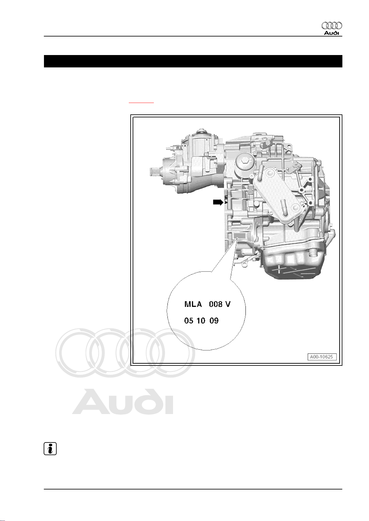
1 Gearbox identification
The „7-speed dual clutch gearbox 0BH (S tronic)“ is installed in
the Audi TT 2007 ►. Allocation ⇒ page 2 .
Audi TT 2007 ➤
The gearbox code letters are located on the top of the gearbox
near the starter and on the gearbox flange -arrow-.
Example:
♦ MLA = gearbox code
♦ 05.10.09 = date of production: 5 October 2009.
♦ The other figures are production-related.
Note
The gearbox code letters are also given on the vehicle data stick‐
ers.
1. Gearbox identification 1
Page 6
Protected by copyright. Copying for private or commercial purposes, in part or in whole, is not
permitted unless authorised by AUDI AG. AUDI AG does not guarantee or accept any liability
with respect to the correctness of information in this document. Copyright by AUDI AG.
Audi TT 2007 ➤
7-speed dual clutch gearbox 0BH (S tronic) - Edition 09.2010
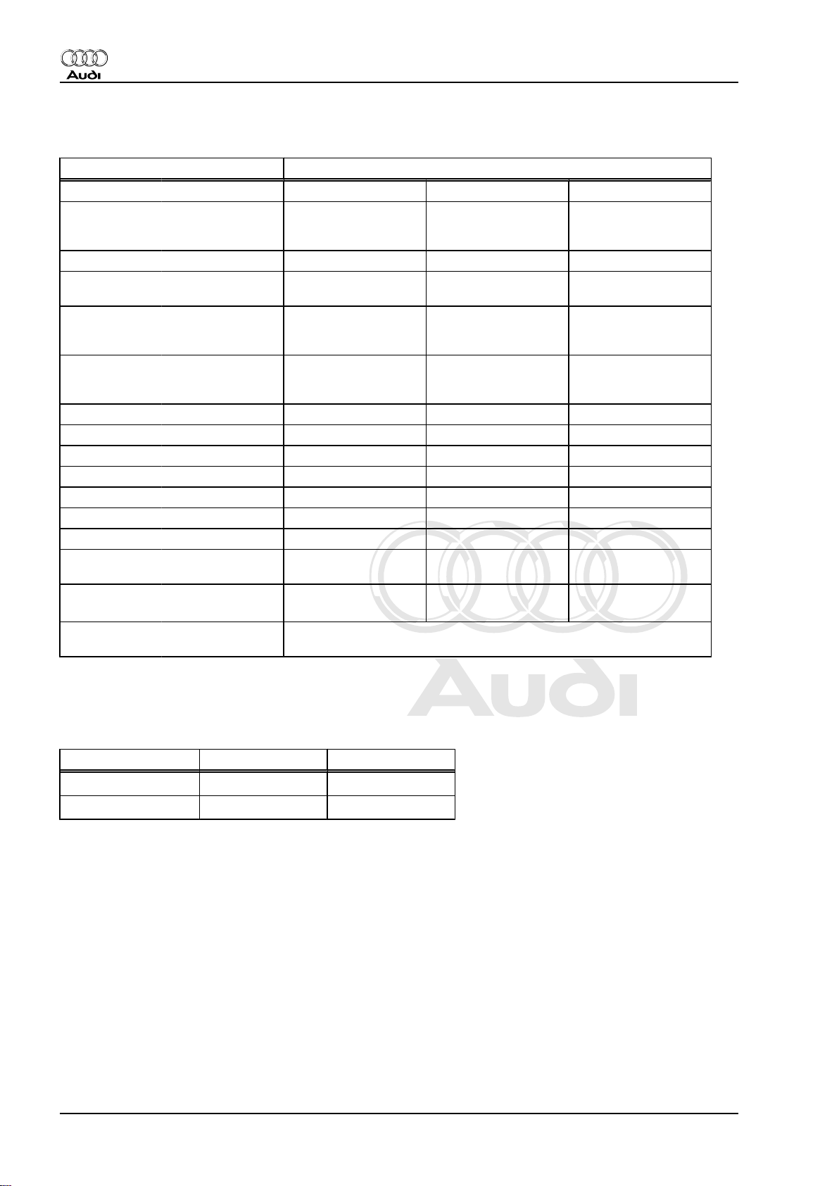
2 Code letters, gearbox allocation, ratios, equipment
Dual clutch gearbox 0BH four-wheel drive
Gearbox Code letters MLA MYD
Allocation Model
Ratios Final drive I
Z2 : Z
1
Overall ratio
i
in top gear
ov.
Allocation: rear
final drive
Manufac‐
tured
Engine
for 1st, 4th, 5th and
reverse gears
Final drive II
for 2nd, 3rd, 6th
and 7th gears
1st gear
2nd gear
3rd gear
4th gear
5th gear
6th gear
7th gear
Reverse
gear
Designation Rear final drive 0BY
fro
m
to
09.10 09.10
Audi TT 2007 ► Audi TT 2007 ►
2.5 ltr. - 250 kW
5-cyl. TFSI
69 : 17 = 4.059 69 : 17 = 4.059
69 : 20 = 3.450 69 : 20 = 3.450
57 : 16 = 3.562 57 : 16 = 3.562
48 : 19 = 2.526 48 : 19 = 2.526
47 : 28 = 1.678 47 : 28 = 1.678
47 : 46 = 1.022 47 : 46 = 1.022
41 : 52 = 0.788 41 : 52 = 0.788
35 : 46 = 0.761 35 : 46 = 0.761
33 : 52 = 0.635 33 : 52 = 0.635
48 : 19 x 53 : 48 =
2.789
2.191 2.191
2.5 ltr. - 250 kW
5-cyl. TFSI
48 : 19 x 53 : 48 =
2.789
2.1 Calculating ratio „i“
Example:
Drive gear ZG1 = 52 ZA1 = 20
Driven gear ZG2 = 33 ZA2 = 69
i = Z2 : Z1 (Z1 = number of teeth on drive gear, Z2 = number of
teeth on driven gear)
iG = gear ratio = ZG2 : ZG1 = 33 : 52 = 0.635
iA = axle ratio = ZA2 : ZA1 = 69 : 20 = 3.450
i
= overall ratio = iG x iA = 0.635 x 3.450 = 2.191
ov.
7th gear Final drive
2 Rep. gr.00 - Technical data
Page 7
Protected by copyright. Copying for private or commercial purposes, in part or in whole, is not
permitted unless authorised by AUDI AG. AUDI AG does not guarantee or accept any liability
with respect to the correctness of information in this document. Copyright by AUDI AG.
7-speed dual clutch gearbox 0BH (S tronic) - Edition 09.2010
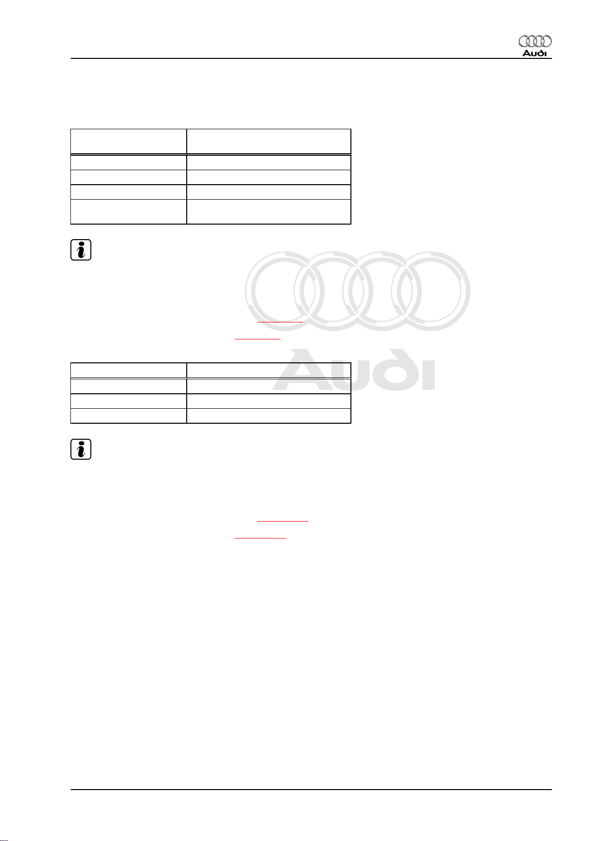
3 Capacities
Gearbox capacity
Capacities Dual clutch gearbox 0BH, four-wheel
drive
Initial filling 7.0 ltr. + 0.1 ltr.
Oil change approx. 5.5 ltr.
Change interval ⇒ Maintenance tables
Lubricant Gear oil for dual clutch gearbox ⇒
Electronic parts catalogue
Note
Use only the correct type of gear oil for dual clutch gearbox 0BH
(available as a replacement part). Other types of lubricant cause
malfunctions and/or failure of the gearbox.
– Checking gear oil level and topping up ⇒ page 63
– Filling up with gear oil after repair ⇒ page 69
Bevel box capacity
Audi TT 2007 ➤
Capacities Bevel box
Initial filling 0.9 ltr.
Oil change Filled for life, no change
Lubricant Gear oil ⇒ Electronic parts catalogue
Note
Use only the correct type of gear oil (available as a replacement
part) for the bevel box. Other types of oil cause malfunctions and/
or failure of the bevel box.
– Checking gear oil level and topping up ⇒ page 115
– Filling up with gear oil after repair ⇒ page 119
3. Capacities 3
Page 8
Protected by copyright. Copying for private or commercial purposes, in part or in whole, is not
permitted unless authorised by AUDI AG. AUDI AG does not guarantee or accept any liability
with respect to the correctness of information in this document. Copyright by AUDI AG.
Audi TT 2007 ➤
7-speed dual clutch gearbox 0BH (S tronic) - Edition 09.2010
4 Safety precautions
4.1 When working on the vehicle
Observe the following precautions to avoid possible injury and/or
damage to the vehicle:
WARNING
Accidents and injury can be caused if a gear is inadvertently
engaged while the engine is running.
♦ Before working on the vehicle while the engine is running,
shift the selector lever into position „P“ and apply the
handbrake.
Observe the following precautions to avoid possible injury and/or
irreparable damage to electrical and electronic components:
♦ Switch off ignition before disconnecting and connecting test
equipment.
Caution
When disconnecting the battery there is a risk of serious dam‐
age to electronic components:
♦ Observe the correct procedure for disconnecting the bat‐
tery.
♦ Always switch off the ignition before disconnecting the
battery.
– Disconnect battery ⇒ Electrical system; Rep. gr. 27 .
4.2 When working on vehicles with start/ stop system
Please note the following when working on vehicles with start/stop
system:
WARNING
Risk of injury due to automatic engine start on vehicles with
start/stop system.
♦ On vehicles with activated start/stop system (this is indi‐
cated by a message in the instrument cluster display), the
engine may start automatically on demand.
♦ Therefore it is important to ensure that the start/stop sys‐
tem is deactivated when performing repairs (switch off
ignition, if required switch on ignition again).
4 Rep. gr.00 - Technical data
Page 9
Protected by copyright. Copying for private or commercial purposes, in part or in whole, is not
permitted unless authorised by AUDI AG. AUDI AG does not guarantee or accept any liability
with respect to the correctness of information in this document. Copyright by AUDI AG.
7-speed dual clutch gearbox 0BH (S tronic) - Edition 09.2010
4.3 When using test equipment while roadtesting the vehicle
Observe the following precautions if test equipment has to be
used when road-testing the vehicle.
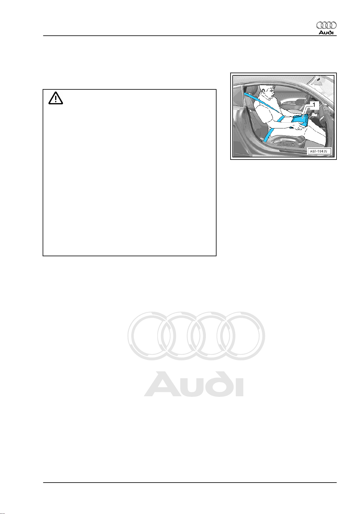
WARNING
Accidents can be caused if the driver is distracted by test
equipment or if test equipment is not secured.
Injuries can be caused if the passenger's airbag is triggered in
a collision.
• The use of test equipment while driving causes distraction.
• There is an increased risk of injury if test equipment is not
secured.
TT Coupé:
Always secure testing equipment to the rear seat with a strap
and have them operated from there by a second person.
TT Roadster:
♦ Move the passenger's seat to the rearmost position.
♦ Use only vehicle diagnostic and service information sys‐
tem -VAS 5052- or diagnosis system -VAS 5053- .
♦ Test equipment may only be operated by the passenger;
the tester -1- must be placed flat on the passenger's lap
as illustrated.
Audi TT 2007 ➤
4. Safety precautions 5
Page 10
Protected by copyright. Copying for private or commercial purposes, in part or in whole, is not
permitted unless authorised by AUDI AG. AUDI AG does not guarantee or accept any liability
with respect to the correctness of information in this document. Copyright by AUDI AG.
Audi TT 2007 ➤
7-speed dual clutch gearbox 0BH (S tronic) - Edition 09.2010
5 Notes on dual clutch gearbox 0BH
5.1 General notes
Gearbox
The layout of the dual clutch gearbox 0BH „S tronic“ is basically
similar to that of a 7-speed manual gearbox. The engine torque
is transferred to the gearbox via the dual-mass flywheel. The two
multi-plate clutches are controlled hydraulically and actuated al‐
ternately so that the gearbox is operated like an automatic gear‐
box, in other words the gears are engaged automatically (but can
also be selected manually via the tiptronic function). There is no
clutch pedal. For further information please refer to ⇒ Self-study
programme No. 454 ; 7-speed dual clutch gearbox 0BT .
Selector mechanism
In selector lever position „P“ the selector lever cable is used to
engage the parking lock mechanically. All other gearshift com‐
mands and selector lever positions are transmitted via the CAN
data bus from the selector lever -J743- (selector mechanism) to
the mechatronic unit for dual clutch gearbox -E313- .
Gear oil (gearbox and bevel box)
The dual clutch gearbox „0BH“ has a common oil system.
This oil system lubricates the gears and shafts, the final drive, the
clutches and the mechatronic unit for dual clutch gearbox -J743- .
Note
Use only the correct type of gear oil for dual clutch gearbox
„0BH“ (available as a replacement part). Other types of oil will
cause malfunctions and/or failure of the gearbox; for part number
refer to ⇒ Electronic parts catalogue .
The bevel box has a separate oil filling ⇒ page 115 .
Note
Use only the correct type of gear oil (available as a replacement
part) for the bevel box. Other types of oil will cause malfunctions
and/or failure of the bevel box; for part number refer to ⇒ Elec‐
tronic parts catalogue .
When does the gear oil filter have to be changed?
Note
The gear oil filter does not always require replacement.
Do not change the filter if:
♦ The gear oil cooler or its O-rings have been renewed and no
coolant has entered the oil system.
♦ Oil seals or O-rings have been renewed in the gearbox.
♦ The oil pan or mechatronic unit have been renewed.
♦ The maintenance interval has been reached.
6 Rep. gr.00 - Technical data
Page 11

Protected by copyright. Copying for private or commercial purposes, in part or in whole, is not
permitted unless authorised by AUDI AG. AUDI AG does not guarantee or accept any liability
with respect to the correctness of information in this document. Copyright by AUDI AG.
7-speed dual clutch gearbox 0BH (S tronic) - Edition 09.2010
The filter must be changed if:
♦ Metal particles are found in the oil.
♦ The clutch is burnt out or mechanically defective.
Disposal regulations for oils
Drained oil must be disposed of properly.
♦ Improper disposal of used oil endangers the environment.
♦ It must not be mixed with solvents, brake fluid, coolant or sim‐
ilar.
♦ Please observe the information shown on the packaging of the
oil.
Variation of gear-change points for gradients
An additional gear change map automatically selects gear
changes for gradients depending on accelerator pedal position
and driving speed.
• Gear change map for extreme uphill gradients is matched to
engine output
• Gear change map for extreme downhill gradients is matched
to the braking effect of the engine
• Increased engine braking effect can also be obtained by di‐
rectly selecting a specific gear via the tiptronic function, e.g.
when towing a trailer on downhill gradients
Audi TT 2007 ➤
5.2 Safety functions of gearbox control unit
In the event of a failure of one or more components/sensors, the
gearbox control unit will activate appropriate backup functions.
This ensures that the gearbox will not be damaged, however, the
function and quality of the gear shifts will be impaired.
Faults detected by the gearbox are classified in four different cat‐
egories.
♦ 1) The fault is stored and a backup programme enables the
vehicle to drive on (in some cases with restrictions). The driver
will not be made aware of the problem, as it is not critical to
driving safety or to the gearbox itself. The selector lever posi‐
tion display in the instrument cluster will continue to show the
selector lever position currently engaged in the normal way. If
at all, the driver will only notice the fault if he experiences
driveability problems, and will then automatically contact an
Audi Service Partner to identify the cause.
♦ 2) Certain positions on the selector lever position display in the
instrument cluster start to flash. This is to inform the driver that
this particular selector lever position is currently not available.
Example: position „D“ is not available when the selector lever
is in position „R“ and the vehicle is still rolling backwards. In
this case, selector lever position „D“ will start to flash on the
selector lever position display in the instrument cluster. The
gearbox control unit prevents the 1st gear from being engaged
in order to avoid damage to the gearbox. 1st gear will be en‐
gaged once the vehicle has come to a standstill.
♦ 3) The complete selector lever position display in the instru‐
ment cluster is lit up and flashing. The current selector lever
position is indicated in the instrument cluster (e.g. „D“ is high‐
lighted). This is an indication that the gearbox has been over‐
loaded or the maximum temperature in the gearbox has been
exceeded (overheating), e.g. towing a load that was too heavy.
♦ 4) If the complete selector lever position display in the instru‐
ment cluster is lit up and flashing, this means that a serious
fault in the gearbox has been identified. The display in the in‐
5. Notes on dual clutch gearbox 0BH 7
Page 12
Protected by copyright. Copying for private or commercial purposes, in part or in whole, is not
permitted unless authorised by AUDI AG. AUDI AG does not guarantee or accept any liability
with respect to the correctness of information in this document. Copyright by AUDI AG.
Audi TT 2007 ➤
7-speed dual clutch gearbox 0BH (S tronic) - Edition 09.2010
strument cluster no longer shows the current selector lever
position. The defect is critical with regard to driving safety or
the gearbox itself. It may no longer be possible to use all gears.
The driver is made aware by the flashing gear selection indi‐
cator that he should immediately contact an Audi Service
Partner.
8 Rep. gr.00 - Technical data
Page 13
Protected by copyright. Copying for private or commercial purposes, in part or in whole, is not
permitted unless authorised by AUDI AG. AUDI AG does not guarantee or accept any liability
with respect to the correctness of information in this document. Copyright by AUDI AG.
7-speed dual clutch gearbox 0BH (S tronic) - Edition 09.2010
6 Notes on tow-starting and towing
Caution
When the vehicle is towed, the selector lever must be set to
position „N“ and the vehicle must not be towed for a distance
of more than 50 km or at a speed in excess of 50 km/h, as the
gearbox would otherwise be seriously damaged.
Note
It is not possible to start the engine by means of tow-starting, for
instance in the case of insufficient battery charge or if the starter
is not working.
Audi TT 2007 ➤
6. Notes on tow-starting and towing 9
Page 14
Protected by copyright. Copying for private or commercial purposes, in part or in whole, is not
permitted unless authorised by AUDI AG. AUDI AG does not guarantee or accept any liability
with respect to the correctness of information in this document. Copyright by AUDI AG.
Audi TT 2007 ➤
7-speed dual clutch gearbox 0BH (S tronic) - Edition 09.2010
7 Repair instructions
Proper tools and the maximum possible care and cleanliness are
essential for satisfactory gearbox repairs. The usual basic safety
precautions also naturally apply when carrying out repair work.
A number of generally applicable instructions for the various re‐
pair procedures are summarised here. They apply to the work
described in this Manual.
Guided Fault Finding, vehicle self-diagnosis and testing system
♦ Before servicing the gearbox, the cause of the fault should be
identified as exactly as possible using the vehicle diagnostic
tester via Guided Fault Finding , Vehicle Self-diagno-
sis and Test Instruments.
Special tools
For a complete list of special tools used in this Workshop Manual
⇒ "Workshop equipment and special tools" .
Gearbox
♦ Do not run the engine or tow the vehicle with the oil pan re‐
moved or when there is no gear oil in the gearbox.
♦ When installing a replacement gearbox, the gear oil level must
be checked and topped up if necessary ⇒ page 63 . For ca‐
pacities refer to ⇒ page 3 , for specifications refer to ⇒
Electronic parts catalogue .
♦ When installing gearbox, ensure that dowel sleeves are fitted
correctly.
10 Rep. gr.00 - Technical data
Page 15
Protected by copyright. Copying for private or commercial purposes, in part or in whole, is not
permitted unless authorised by AUDI AG. AUDI AG does not guarantee or accept any liability
with respect to the correctness of information in this document. Copyright by AUDI AG.
7-speed dual clutch gearbox 0BH (S tronic) - Edition 09.2010
O-rings, oil seals and gaskets
♦ Renew O-rings, oil seals and gaskets.
♦ After removing gaskets and seals, always inspect the contact
surface on the housing or shaft for burrs resulting from removal
or for other signs of damage.
♦ Renew gaskets: completely remove the old gasket and clean
the sealing surfaces thoroughly.
♦ Lightly lubricate O-rings with gear oil before installation to pre‐
vent them being trapped and damaged during assembly.
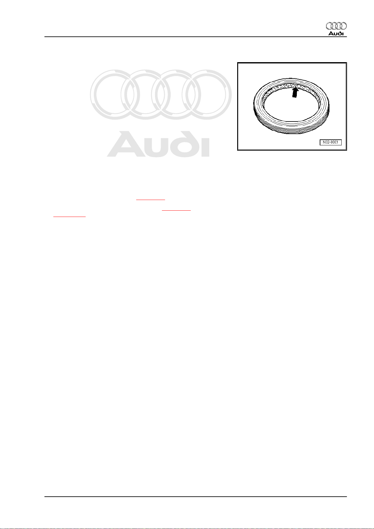
♦ Lightly oil the outer circumference of oil seals and fill the space
between the sealing lips -arrow- about half full with sealing
grease -G 052 128 A1- .
♦ Do not use any other lubricants where gear oil is specified.
Otherwise, there is a risk of problems occurring in the gearbox
hydraulics.
♦ The open side of the oil seal should face the side containing
the fluid.
♦ Observe rules for cleanliness ⇒ page 12 .
♦ After installing, check the gear oil level ⇒ page 63 or
⇒ page 115 and rectify as necessary.
Locking elements
♦ Do not over-stretch circlips.
♦ Renew circlips which have been damaged or over-tensioned.
♦ Circlips must be properly seated in the base of the groove.
Nuts, bolts
♦ Slacken bolts in reverse sequence to the specified tightening
sequence.
♦ Nuts and bolts which secure covers and housings should be
loosened and tightened in diagonal sequence and in stages if
no tightening sequence is specified.
♦ Renew self-locking nuts.
♦ Use a wire brush to clean the threads of bolts which are se‐
cured with locking fluid. Then install bolts with locking fluid; for
locking fluid refer to ⇒ Electronic parts catalogue .
♦ The tightening torques stated apply to non-oiled nuts and
bolts.
♦ Where instructions specify a torque setting plus an additional
angle, these bolts must be tightened to the specified torque
and then turned through the specified angle, e.g. 40 Nm + 90°
(90° = a quarter turn).
Audi TT 2007 ➤
7.1 Contact corrosion!
Contact corrosion can occur if non-approved fasteners are used
on the vehicle (bolts, nuts, washers etc.).
For this reason, only fasteners with a special surface coating are
fitted.
Rubber or plastic parts and adhesives also consist of non-con‐
ductive materials.
If you are not sure whether used parts can be re-installed, always
fit new parts ⇒ Electronic parts catalogue .
7. Repair instructions 11
Page 16

Protected by copyright. Copying for private or commercial purposes, in part or in whole, is not
permitted unless authorised by AUDI AG. AUDI AG does not guarantee or accept any liability
with respect to the correctness of information in this document. Copyright by AUDI AG.
Audi TT 2007 ➤
7-speed dual clutch gearbox 0BH (S tronic) - Edition 09.2010
Please note:
♦ Use only genuine spare parts: these have been fully tested
and are compatible with aluminium.
♦ We recommend the use of accessories approved by Audi.
♦ Damage resulting from contact corrosion is not covered by the
warranty.
7.2 Rules for cleanliness
♦ Carefully clean connection points and the surrounding area
with engine cleaner or brake cleaner and dry thoroughly before
opening.
♦ Use cleaning fluid -D 009 401 04- to clean the gearbox and its
components.
♦ Use lint-free cloths for cleaning, such as the „WYPALL X70 /
WORKHORSE“ cloth from Kimberly-Clark Professional.
♦ Seal off open lines and connections immediately with clean
plugs or sealing caps from engine bung set -VAS 6122- im‐
mediately.
♦ Place removed parts on a clean surface and cover them over.
Use sheeting and paper. Use lint-free cloths.
♦ Carefully cover or seal open components if repairs cannot be
carried out immediately.
♦ Only install clean components: do not remove replacement
parts from packaging until just before installation.
♦ Protect unplugged electrical connectors against dirt and mois‐
ture and make sure connections are dry when attaching.
12 Rep. gr.00 - Technical data
Page 17
Protected by copyright. Copying for private or commercial purposes, in part or in whole, is not
permitted unless authorised by AUDI AG. AUDI AG does not guarantee or accept any liability
with respect to the correctness of information in this document. Copyright by AUDI AG.
7-speed dual clutch gearbox 0BH (S tronic) - Edition 09.2010
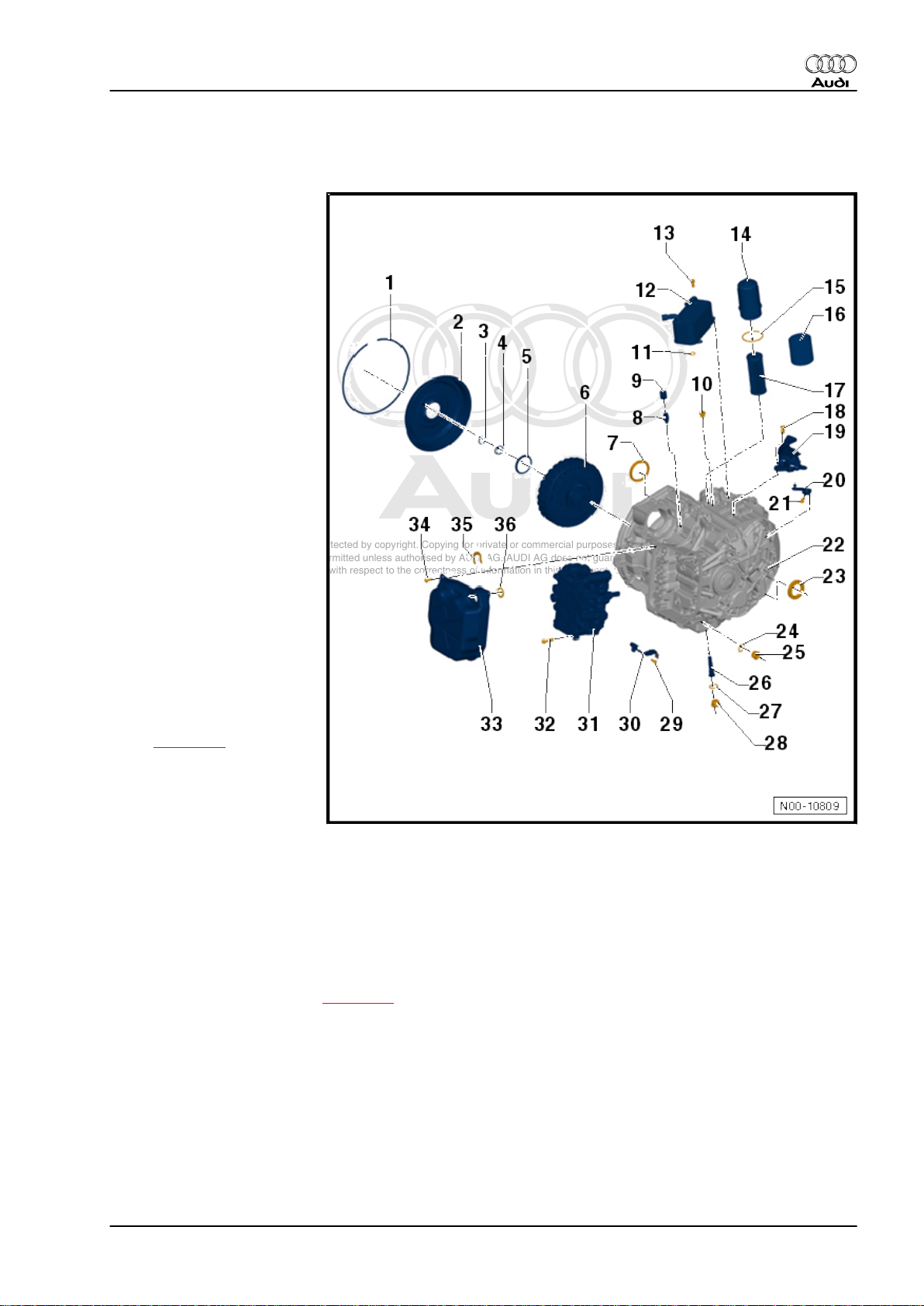
8 Exploded view - dual clutch gearbox
1 - Circlip
❑ For cover for multiple
clutch
❑ Renew
2 - Cover for multiple clutch
❑ There is currently no
provision for repairs to
the clutch
3 - Circlip
❑ Renew
4 - Shim
❑ There is currently no
provision for repairs to
the clutch
5 - Tapered ring
❑ There is currently no
provision for repairs to
the clutch
6 - Multiple clutch
❑ There is currently no
provision for repairs to
the clutch
7 - Oil seal
❑ Installed in dual clutch
gearbox (right-side),
facing bevel box
❑ Removing and installing
⇒ page 99
8 - Breather pipe
❑ Pressed into gearbox
❑ Must be renewed if re‐
moved
9 - Breather cap
❑ Fitted onto breather pipe
10 - Screw plug
11 - O-ring
❑ Always renew
12 - Gear oil cooler
❑ Removing and installing ⇒ page 73
13 - Bolt
❑ 20 Nm and then turn 45° further
14 - Filter housing
❑ 20 Nm
15 - O-ring
❑ Always renew
Audi TT 2007 ➤
8. Exploded view - dual clutch gearbox 13
Page 18
Protected by copyright. Copying for private or commercial purposes, in part or in whole, is not
permitted unless authorised by AUDI AG. AUDI AG does not guarantee or accept any liability
with respect to the correctness of information in this document. Copyright by AUDI AG.
Audi TT 2007 ➤
7-speed dual clutch gearbox 0BH (S tronic) - Edition 09.2010
16 - Heat shield
17 - Gear oil filter
❑ Notes on oil filling and filter change ⇒ page 6
❑ Removing and installing ⇒ page 75
18 - Bolt
❑ 10 Nm and then turn 45° further
19 - Cable support bracket
❑ Secures selector lever cable to gearbox
20 - Gearbox selector lever
21 - Bolt
❑ 10 Nm and then turn 90° further
22 - Gearbox
23 - Oil seal
❑ For drive shaft (left-side)
❑ Removing and installing ⇒ page 95
24 - Seal
❑ Always renew
25 - Oil drain plug
❑ 10 Nm and then turn 30° further
❑ For mechatronic unit
26 - Overflow pipe
❑ 3 Nm
Caution
♦Keep exactly to specified
torque.
♦The overflow pipe can
break between the
thread and the collar.
Note
❑ Draining and filling oil ⇒ page 69
27 - Seal
❑ Always renew
28 - Oil drain plug
❑ 45 Nm
❑ For gearbox
29 - Bolt
❑ Tightening torque ⇒ Item 29 (page 85)
30 - Gearbox input speed sender -G182- / clutch temperature sender -G509-
❑ The two senders are combined in one component and can only be renewed together
❑ Removing and installing ⇒ page 93
31 - Mechatronic unit for dual clutch gearbox -J743-
❑ Removing and installing ⇒ page 89
32 - Bolt
❑ Tightening torque ⇒ Item 32 (page 85)
14 Rep. gr.00 - Technical data
Page 19

Protected by copyright. Copying for private or commercial purposes, in part or in whole, is not
permitted unless authorised by AUDI AG. AUDI AG does not guarantee or accept any liability
with respect to the correctness of information in this document. Copyright by AUDI AG.
❑ Always renew
33 - Oil pan
❑ With gasket
❑ Removing and installing ⇒ page 86
❑ Always renew
34 - Bolt
❑ Tightening torque ⇒ Item 34 (page 85)
❑ Always renew
35 - Securing clip
❑ Always renew
36 - O-ring
❑ Always renew
Audi TT 2007 ➤
7-speed dual clutch gearbox 0BH (S tronic) - Edition 09.2010
8. Exploded view - dual clutch gearbox 15
Page 20

Protected by copyright. Copying for private or commercial purposes, in part or in whole, is not
permitted unless authorised by AUDI AG. AUDI AG does not guarantee or accept any liability
with respect to the correctness of information in this document. Copyright by AUDI AG.
Audi TT 2007 ➤
7-speed dual clutch gearbox 0BH (S tronic) - Edition 09.2010
30 – Clutch
1 There is currently no provision for re‐
pairs to the clutch.
16 Rep. gr.30 - Clutch
Page 21
Protected by copyright. Copying for private or commercial purposes, in part or in whole, is not
permitted unless authorised by AUDI AG. AUDI AG does not guarantee or accept any liability
with respect to the correctness of information in this document. Copyright by AUDI AG.
7-speed dual clutch gearbox 0BH (S tronic) - Edition 09.2010
34 – Controls, housing
1 Electrical/electronic components and fit‐
ting locations
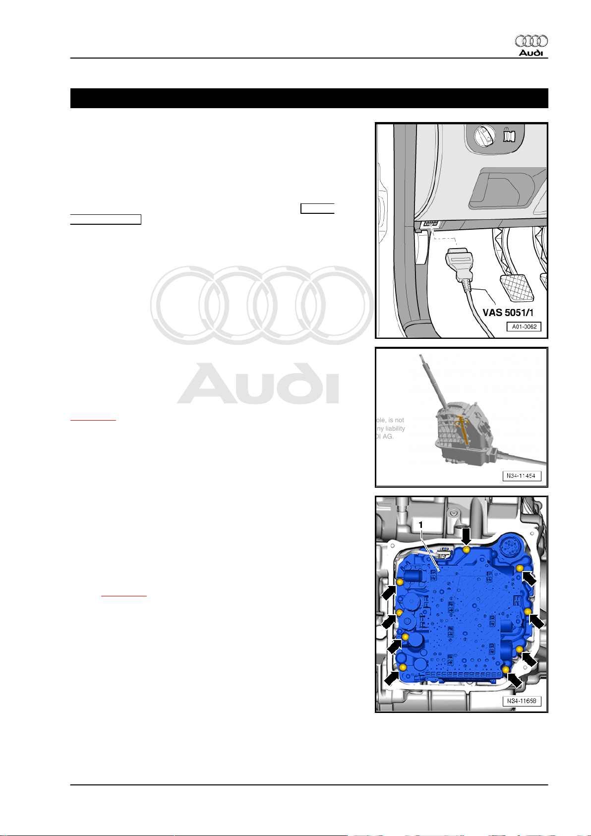
Diagnostic connection
Fitting location: The diagnostic connection is located below the
knee padding to the left of the steering wheel.
The components listed below can be tested with the Guided
Fault Finding function in the vehicle diagnostic tester .
Audi TT 2007 ➤
Selector lever lock solenoid -N110-
Fitting location: The selector lever lock solenoid -N110- is a com‐
ponent part of the shift unit.
The selector lever lock solenoid -N110- cannot be renewed sep‐
arately. The shift unit must be renewed in the event of a fault
⇒ page 31 .
Mechatronic unit for dual clutch gearbox -J743-
Fitting location: The mechatronic unit for dual clutch gearbox J743- -1- is bolted to the front of the gearbox housing -arrowsand covered by the gearbox oil pan.
The control unit is an integrated component of the mechatronic
unit for dual clutch gearbox -J743- .
Removing and installing mechatronic unit for dual clutch gearbox
-J743- ⇒ page 89
1. 17
Page 22
Protected by copyright. Copying for private or commercial purposes, in part or in whole, is not
permitted unless authorised by AUDI AG. AUDI AG does not guarantee or accept any liability
with respect to the correctness of information in this document. Copyright by AUDI AG.
Audi TT 2007 ➤
7-speed dual clutch gearbox 0BH (S tronic) - Edition 09.2010
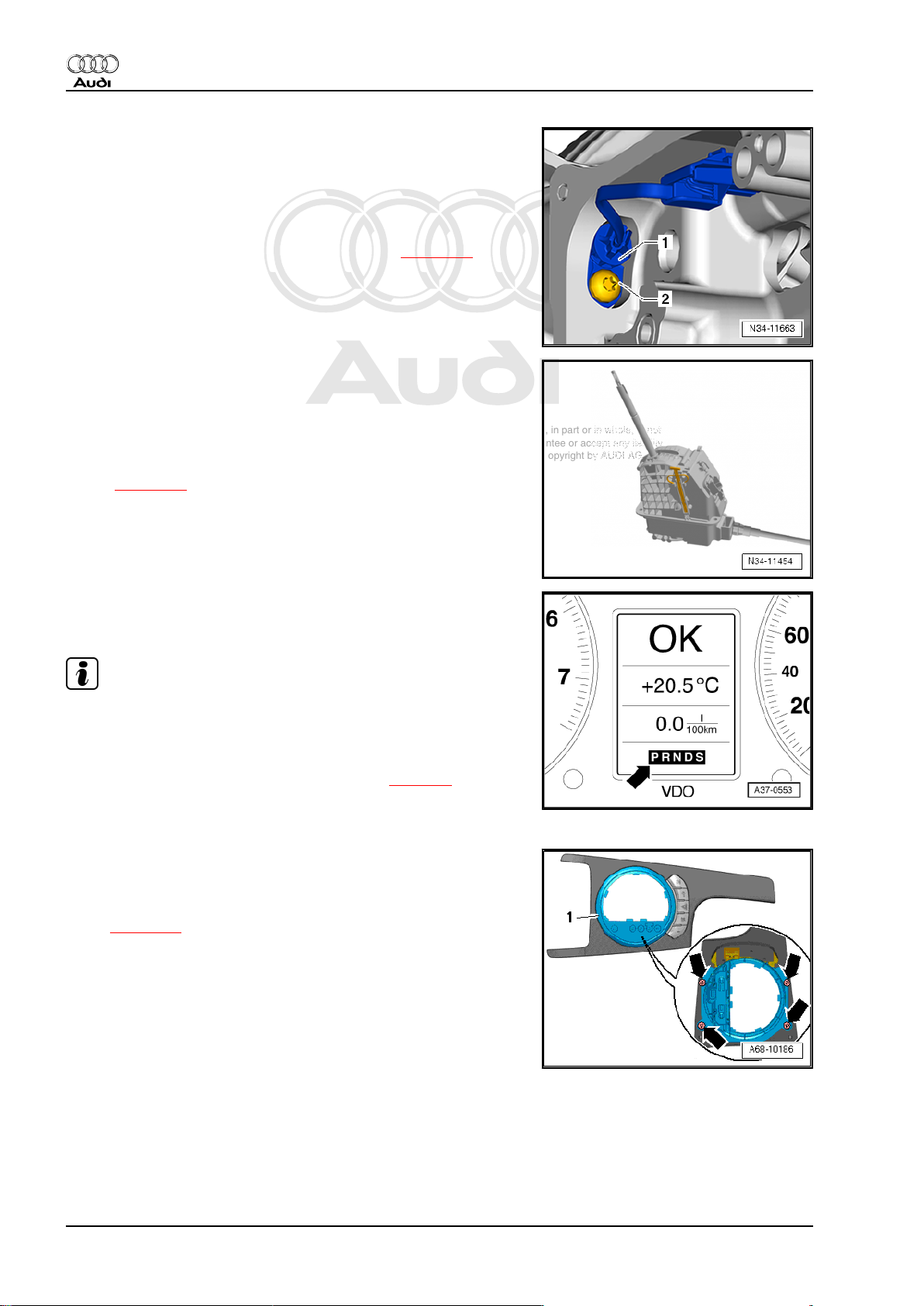
Gearbox input speed sender -G182- / clutch temperature sender
-G509-
Fitting location: The gearbox input speed sender -G182- / clutch
temperature sender -G509- -1- is secured to the gearbox housing
with bolt -2-.
Removing and installing gearbox input speed sender -G182- / oil
temperature sender for multi-plate clutch -G509- ⇒ page 93 .
Selector lever sensors control unit -J587- with selector lever E313- , tiptronic switch -F189- , selector lever locked in position
P switch -F319-
Fitting location: The components are integrated in the printed cir‐
cuit of the shift unit; they cannot be renewed separately.
The shift unit must be renewed if one of the components is de‐
fective ⇒ page 31 .
Selector lever position display -Y6-
Fitting location: integrated into instrument cluster.
Note
The selector lever position display can only be renewed together
with the instrument cluster.
If the selector lever position display flashes or lights up, please
refer to safety functions of gearbox control unit ⇒ page 7 .
Removing and installing instrument cluster ⇒ Electrical system;
Rep. gr. 90
Selector lever display illumination bulb -L101-
Fitting location: in trim for selector lever boot -1-.
Removing and installing selector lever display illumination bulb L101- ⇒ page 26
18 Rep. gr.34 - Controls, housing
Page 23
Protected by copyright. Copying for private or commercial purposes, in part or in whole, is not
permitted unless authorised by AUDI AG. AUDI AG does not guarantee or accept any liability
with respect to the correctness of information in this document. Copyright by AUDI AG.
7-speed dual clutch gearbox 0BH (S tronic) - Edition 09.2010
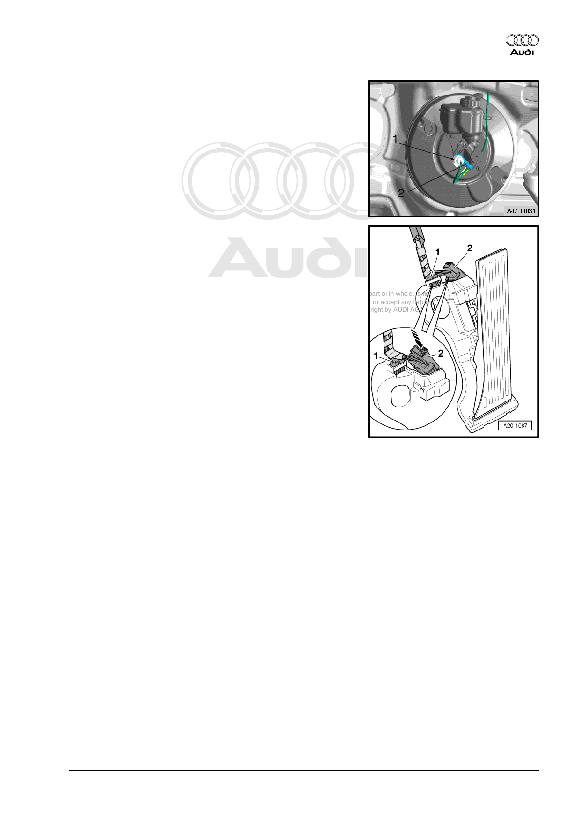
Brake light switch -F-
Fitting location: The brake light switch -2- is located on the brake
master cylinder.
Removing and installing brake light switch ⇒ Brake system; Rep.
gr. 45 .
Kick-down switch -F8-
An adapted value from accelerator position sender -G79- / accel‐
erator position sender 2 -G185- (integrated in accelerator pedal
module) is stored in the engine control unit as the kickdown signal.
♦ Signal is transmitted from engine control unit to gearbox con‐
trol unit via CAN bus.
Removing and installing accelerator pedal module ⇒ Fuel supply
system, petrol engines; Rep. gr. 20 .
Audi TT 2007 ➤
1. 19
Page 24
Protected by copyright. Copying for private or commercial purposes, in part or in whole, is not
permitted unless authorised by AUDI AG. AUDI AG does not guarantee or accept any liability
with respect to the correctness of information in this document. Copyright by AUDI AG.
Audi TT 2007 ➤
7-speed dual clutch gearbox 0BH (S tronic) - Edition 09.2010
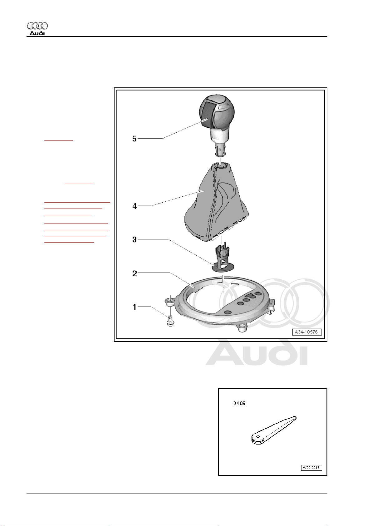
2 Exploded view - selector lever handle, selector lever display illumina‐
tion bulb -L101-
1 - Bolt
❑ 1 Nm
2 - Trim for selector lever boot
with selector lever display illu‐
mination bulb -L101-
❑ Removing and installing
⇒ page 26
3 - Guide
4 - Selector lever boot
❑ Detaching selector lever
boot from selector lever
handle ⇒ page 22
5 - Selector lever handle
❑ ⇒ „2.1 Removing and in‐
stalling selector lever
handle“, page 20
❑ ⇒ „2.3 Moving interlock
button on selector lever
handle into installation
position“, page 24
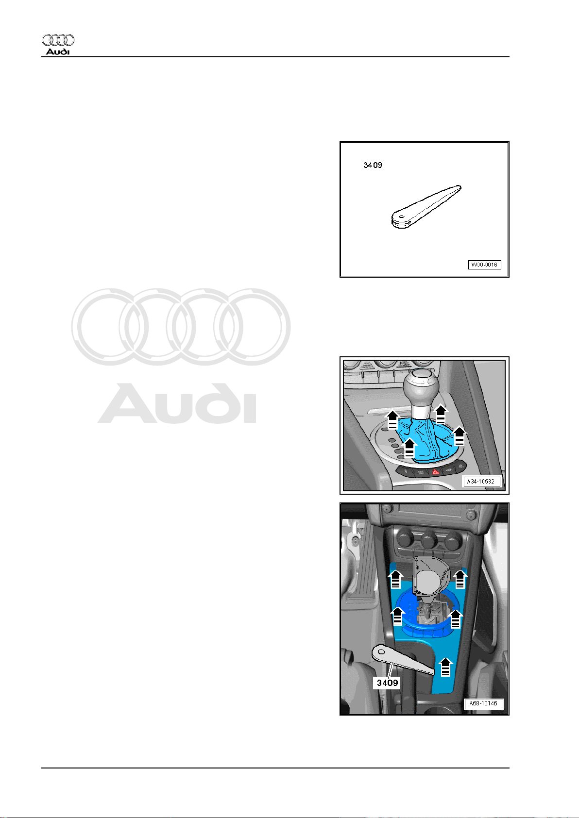
2.1 Removing and installing selector lever handle
Special tools and workshop equipment required
♦ Removal wedge -3409-
20 Rep. gr.34 - Controls, housing
Page 25
Protected by copyright. Copying for private or commercial purposes, in part or in whole, is not
permitted unless authorised by AUDI AG. AUDI AG does not guarantee or accept any liability
with respect to the correctness of information in this document. Copyright by AUDI AG.
7-speed dual clutch gearbox 0BH (S tronic) - Edition 09.2010
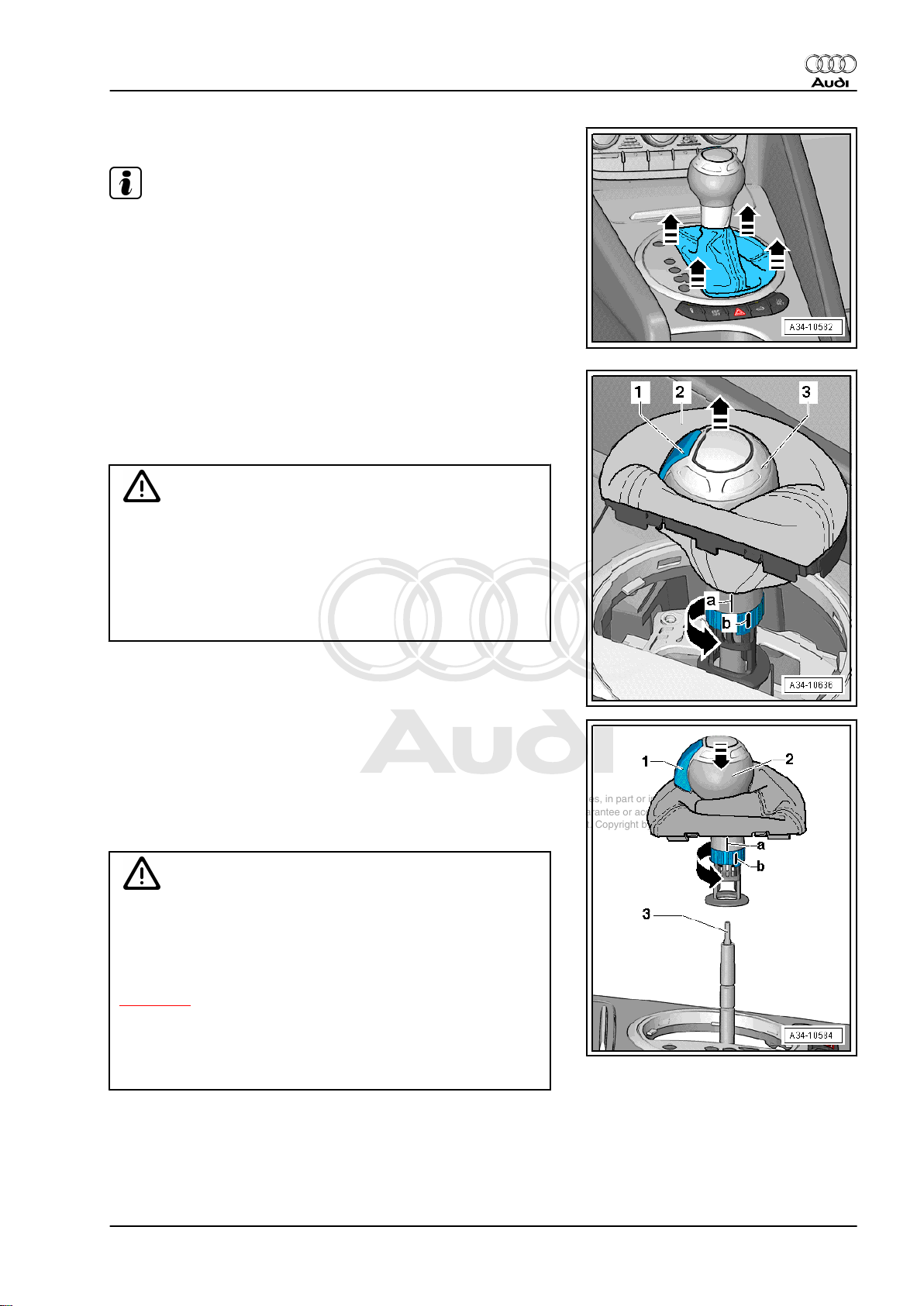
Removing
Note
The selector lever handle is removed together with the selector
lever boot.
– Apply handbrake.
– Shift selector lever into position „N“.
– Unclip selector lever boot on both sides using removal wedge
-3409- and lift it off -arrows-.
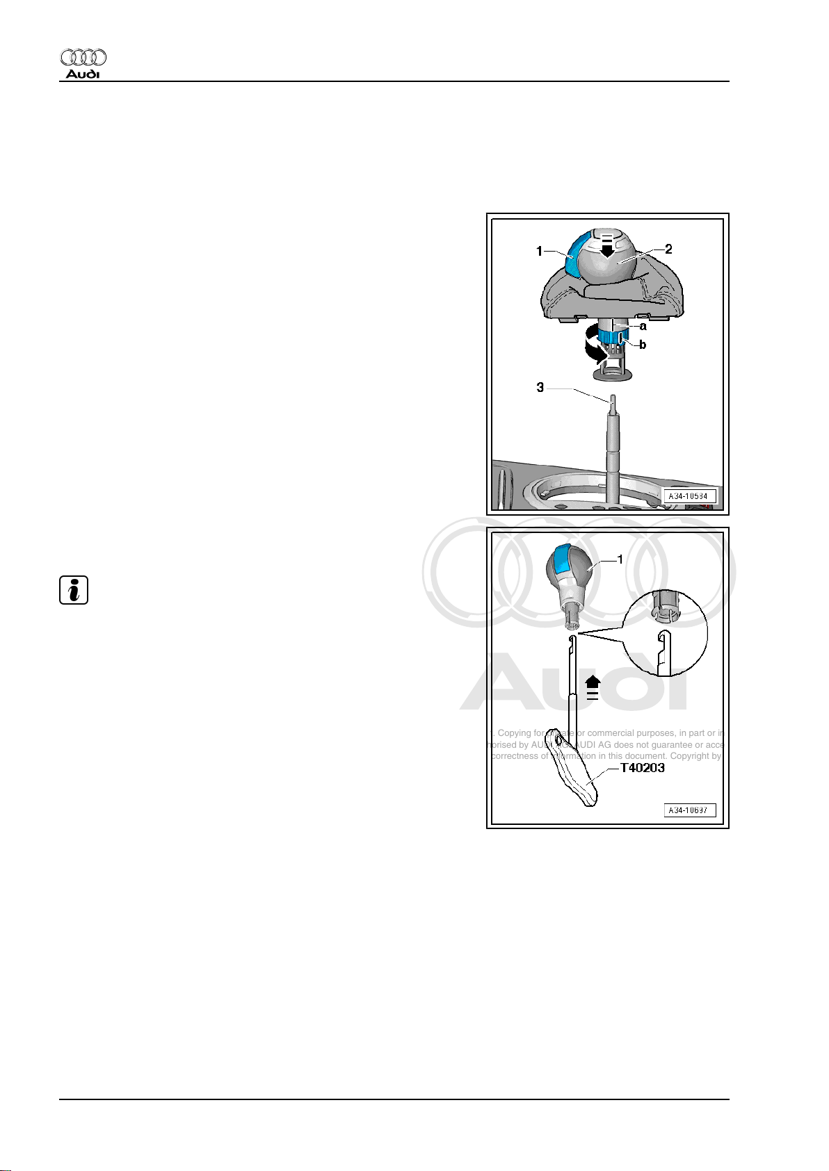
– Turn selector lever boot -2- inside out over selector lever han‐
dle -3-.
– Turn locking ring in direction of -arrow- as far as stop.
• Raised lug -b- on locking ring is moved away from lug -a-.
Caution
Audi TT 2007 ➤
Risk of damage to the selector mechanism.
Do not touch the interlock button -1- on the selector lever han‐
dle when pulling off the handle.
Otherwise the selector lever handle or the pull rod of the se‐
lector mechanism will be damaged when the handle is pulled
off.
– Pull off selector lever handle together with selector lever boot
upwards -arrow-, taking care not to touch interlock button -1-.
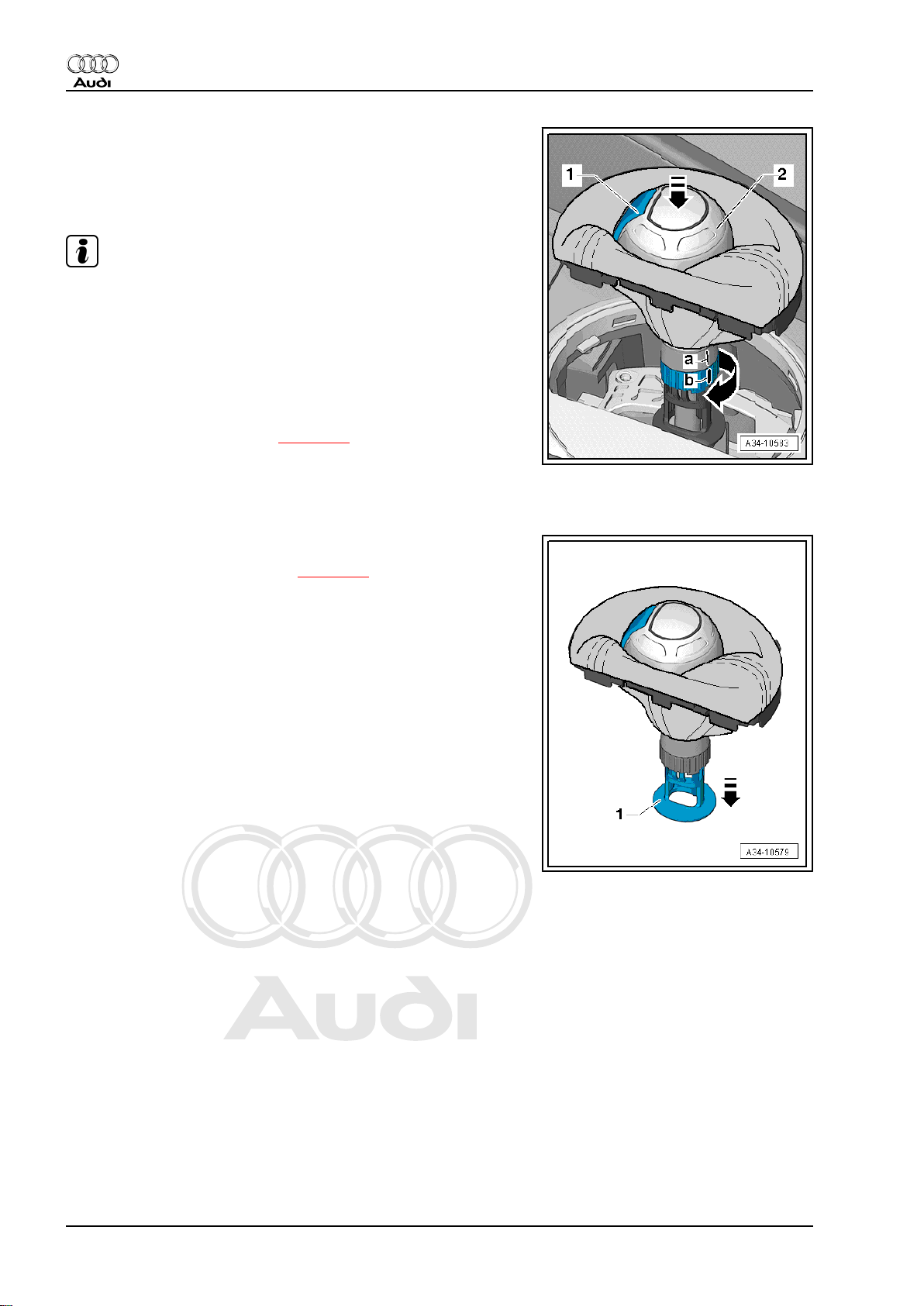
Installing
Installation is carried out in reverse sequence; note the following:
– Turn locking ring in direction of -arrow- as far as stop.
• Raised lug -b- on locking ring is moved away from lug -a-.
• Interlock button faces direction of travel.
Caution
Risk of damage to the selector mechanism.
The interlock button -1- must protrude from the selector lever
handle during installation. If the interlock button was pressed
in by mistake when the handle was removed, the interlock but‐
ton must be moved back to its installation position
⇒ page 24 .
If the interlock button has been pressed in and the handle is
installed with the interlock button in this position, the handle
and the pull rod of the selector mechanism -3- will be damaged
irreparably.
– Carefully press selector lever handle fully into selector lever,
taking care not to touch interlock button -1-.
• The handle must engage in the annular groove on the selector
lever.
2. Exploded view - selector lever handle, selector lever display illumination bulb L101 21
Page 26
Protected by copyright. Copying for private or commercial purposes, in part or in whole, is not
permitted unless authorised by AUDI AG. AUDI AG does not guarantee or accept any liability
with respect to the correctness of information in this document. Copyright by AUDI AG.
Audi TT 2007 ➤
7-speed dual clutch gearbox 0BH (S tronic) - Edition 09.2010
– Turn locking ring in direction of -arrow- as far as stop.
• It must be possible to turn the locking ring; press handle if
necessary.
• Lug -a- must align with raised lug -b- on locking ring.
Note
♦
The handle is not locked until the locking ring has been turned.
Only then can you press the interlock button on the handle.
♦
There may be increased resistance when you press the inter‐
lock button for the first time after installation.
– Press interlock button -1- on selector lever handle.
– Fold selector lever boot down and clip it in.
– Check selector mechanism ⇒ page 30 .
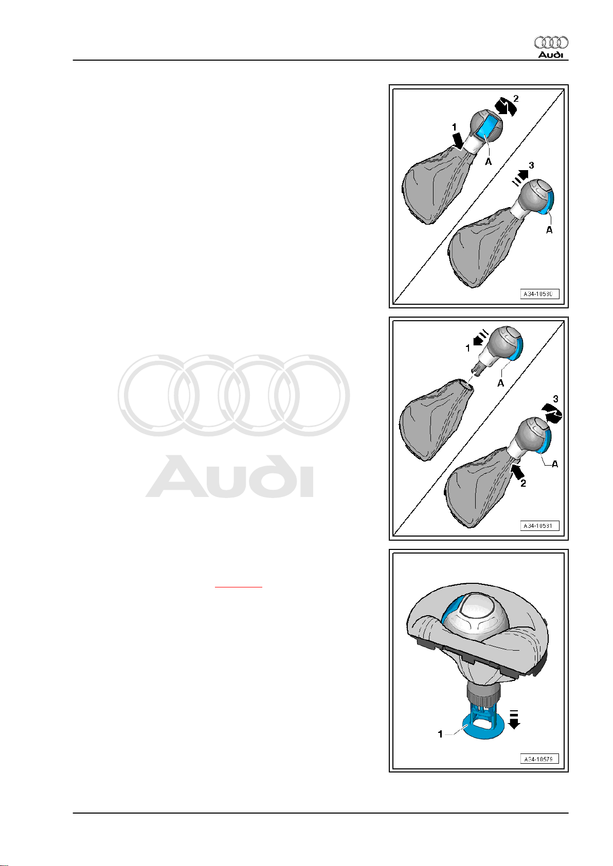
2.2 Detaching selector lever boot from se‐
lector lever handle
Procedure:
– Remove selector lever handle ⇒ page 20 .
– Pull guide -1- off in direction of -arrow-.
22 Rep. gr.34 - Controls, housing
Page 27
Protected by copyright. Copying for private or commercial purposes, in part or in whole, is not
permitted unless authorised by AUDI AG. AUDI AG does not guarantee or accept any liability
with respect to the correctness of information in this document. Copyright by AUDI AG.
7-speed dual clutch gearbox 0BH (S tronic) - Edition 09.2010
• Do not touch interlock button -A- when selector lever handle
has been removed.
– Hold upper end of selector lever boot -arrow 1-.
– Turn selector lever handle in direction of -arrow 2- and pull it
off -arrow 3-.
Installing selector lever boot with selector lever handle:
• Do not touch interlock button -A- when selector lever handle
has been removed.
– Insert selector lever handle in selector lever boot -arrow 1-
(with interlock button turned 90° out of position towards left).
– Hold upper end of selector lever boot -arrow 2-.
– Turn selector lever handle in direction of -arrow 3-.
Audi TT 2007 ➤
– Clip guide -1- upwards into handle in opposite direction of
-arrow-.
– Install selector lever handle ⇒ page 20 .
2. Exploded view - selector lever handle, selector lever display illumination bulb L101 23
Page 28
Protected by copyright. Copying for private or commercial purposes, in part or in whole, is not
permitted unless authorised by AUDI AG. AUDI AG does not guarantee or accept any liability
with respect to the correctness of information in this document. Copyright by AUDI AG.
Audi TT 2007 ➤
7-speed dual clutch gearbox 0BH (S tronic) - Edition 09.2010
2.3 Moving interlock button on selector lever handle into installation position
Special tools and workshop equipment required
♦ Release tool -T40203-
Selector lever handle with interlock button:
• Installation position: the interlock button -1- must protrude
from the selector lever handle.
If the interlock button has been pressed in, it must be moved back
into its installation position so that the selector lever handle can
be installed.
– Carefully insert release tool -T40203- into selector lever han‐
dle -1- as far as stop.
Note
For illustration purposes, the handle is shown without selector
lever boot.
• Recess on release tool -T40203- should face interlock button,
hook should point towards left.
24 Rep. gr.34 - Controls, housing
Page 29
Protected by copyright. Copying for private or commercial purposes, in part or in whole, is not
permitted unless authorised by AUDI AG. AUDI AG does not guarantee or accept any liability
with respect to the correctness of information in this document. Copyright by AUDI AG.
7-speed dual clutch gearbox 0BH (S tronic) - Edition 09.2010
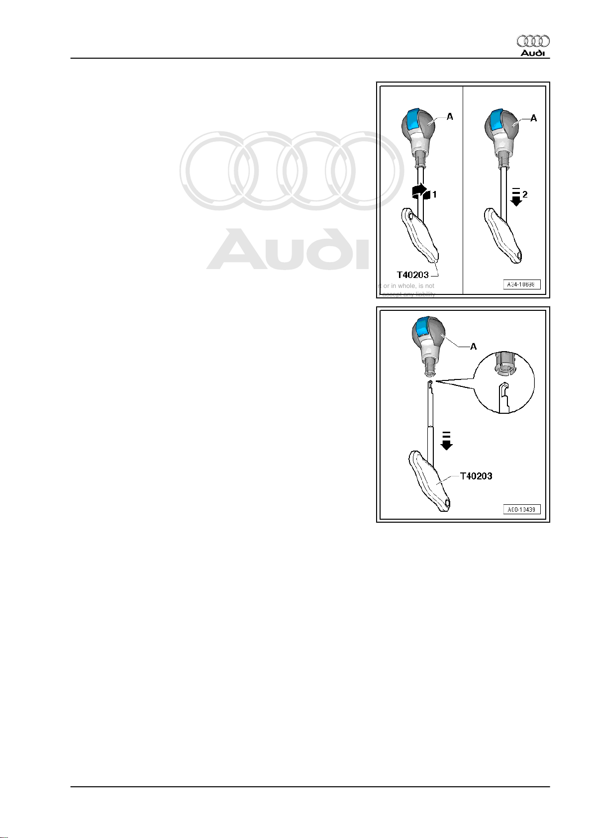
– Hold selector lever handle -A- and turn release tool -T40203-
180° in direction of -arrow 1-.
– Hold handle and carefully pull out release tool -T40203-
-arrow 2-.
• When pulling out release tool -T40203- , interlock button -Aon selector lever handle is pressed out and locked in position.
• Do not touch interlock button on selector lever handle before
installing handle so that interlock button is not pressed in
again.
Audi TT 2007 ➤
2. Exploded view - selector lever handle, selector lever display illumination bulb L101 25
Page 30
Protected by copyright. Copying for private or commercial purposes, in part or in whole, is not
permitted unless authorised by AUDI AG. AUDI AG does not guarantee or accept any liability
with respect to the correctness of information in this document. Copyright by AUDI AG.
Audi TT 2007 ➤
7-speed dual clutch gearbox 0BH (S tronic) - Edition 09.2010
3 Removing and installing selector lev‐
er display illumination bulb -L101-
Special tools and workshop equipment required
♦ Removal wedge -3409-
Removing
– Apply handbrake.
– Shift selector lever into position „N“.
– Switch off ignition.
– Unclip selector lever boot on both sides using removal wedge
-3409- and lift it off -arrows-.
– Pull selector lever boot up and over handle.
– Using removal wedge -3409- , pry trim panel for centre console
out of centre console -arrows-.
– Unplug electrical connectors and remove trim panel for centre
console.
26 Rep. gr.34 - Controls, housing
Page 31

Protected by copyright. Copying for private or commercial purposes, in part or in whole, is not
permitted unless authorised by AUDI AG. AUDI AG does not guarantee or accept any liability
with respect to the correctness of information in this document. Copyright by AUDI AG.
7-speed dual clutch gearbox 0BH (S tronic) - Edition 09.2010
– Remove bolts -arrows- and detach trim for selector lever boot
-1- together with selector lever display illumination bulb L101- .
Installing
Installation is carried out in reverse sequence; note the following:
Tightening torque:
• ⇒ „2 Exploded view - selector lever handle, selector lever dis‐
play illumination bulb L101 “, page 20
– Make sure trim panel engages audibly in centre console.
Audi TT 2007 ➤
3. Removing and installing selector lever display illumination bulb L101 27
Page 32

Protected by copyright. Copying for private or commercial purposes, in part or in whole, is not
permitted unless authorised by AUDI AG. AUDI AG does not guarantee or accept any liability
with respect to the correctness of information in this document. Copyright by AUDI AG.
Audi TT 2007 ➤
7-speed dual clutch gearbox 0BH (S tronic) - Edition 09.2010
4 Exploded view - selector mechanism
1 - Nut
❑ 8 Nm
❑ Secures selector mech‐
anism to body
❑ 4x
2 - Shift unit
❑ With integrated printed
circuit for selector
mechanism ( selector
lever -E313- )
❑ Incorporates the follow‐
ing components: selec‐
tor lever sensors control
unit -J587- with selector
lever -E313- , tiptronic
switch -F189- , selector
lever locked in position
P switch -F319- and se‐
lector lever lock sole‐
noid -N110-
❑ Can be checked via
Guided Fault Find-
ing function using vehi‐
cle diagnostic tester
❑ Selector lever sensors
control unit -J587- with
selector lever -E313- ,
tiptronic switch -F189- ,
selector lever locked in
position P switch -F319and selector lever lock
solenoid -N110- can on‐
ly be renewed together
with shift unit as a com‐
plete unit ⇒ page 31
❑ Selector lever cable can
only be renewed togeth‐
er with complete shift unit ⇒ page 31
❑ Manual release of selector mechanism ⇒ page 28
❑ Removing and installing ⇒ page 31
❑ Do not grease selector lever cable
3 - Cable support bracket
❑ For selector lever cable
4 - Gearbox selector lever
5 - Bolt
❑ 15 Nm
❑ For adjusting selector lever cable
4.1 Operating manual release of selector mechanism from position „P“
Special tools and workshop equipment required
28 Rep. gr.34 - Controls, housing
Page 33

Protected by copyright. Copying for private or commercial purposes, in part or in whole, is not
permitted unless authorised by AUDI AG. AUDI AG does not guarantee or accept any liability
with respect to the correctness of information in this document. Copyright by AUDI AG.
7-speed dual clutch gearbox 0BH (S tronic) - Edition 09.2010
♦ Removal wedge -3409-
♦ The selector lever lock solenoid -N110- locks the selector lever
in position „P“. The selector lever can then only be shifted out
of position „P“ when the ignition is on / the engine is running,
the brake pedal is depressed and the button on the selector
lever handle is pressed ⇒ page 30 .
♦ In the event of a fault in the power supply to the selector lever
lock solenoid (discharged battery or defective fuse) or if the
solenoid is defective, the selector lever cannot be shifted out
of position „P“. The vehicle cannot be moved because the
parking lock is engaged.
In this case:
– Check fuses ⇒ Current flow diagrams, Electrical fault finding
and Fitting locations.
– Check battery voltage ⇒ Electrical system; General informa‐
tion; Rep. gr. 27 .
If fault finding has not been successful and selector lever can still
not be shifted from „P“ the solenoid can be released manually.
However, if the selector lever is then moved back to „P“ it will
remain locked in position „P“ once again.
Procedure
– Unclip selector lever boot on both sides using removal wedge
-3409- and lift it off -arrows-.
– Pull selector lever boot up and over handle.
Audi TT 2007 ➤
Note
The selector lever handle does not have to be removed in order
to operate the manual release mechanism.
4. Exploded view - selector mechanism 29
Page 34

Protected by copyright. Copying for private or commercial purposes, in part or in whole, is not
permitted unless authorised by AUDI AG. AUDI AG does not guarantee or accept any liability
with respect to the correctness of information in this document. Copyright by AUDI AG.
Audi TT 2007 ➤
7-speed dual clutch gearbox 0BH (S tronic) - Edition 09.2010
– Use a screwdriver -1- or similar to release selector lever lock
solenoid in direction of -arrow- and hold in this position.
Caution
If component parts of the shift unit are damaged, the shift unit
has to be renewed as a complete unit.
• The solenoid will then release the selector lever.
– With solenoid released, press interlock button on selector lev‐
er handle and shift selector lever out of „P“.
Note
However, if the selector lever is now moved back to „P“ the se‐
lector lever lock solenoid will once again mechanically lock it in
position „P“. The solenoid must be released once again.
4.2 Checking selector mechanism and igni‐
tion key removal lock
♦ It should not be possible to operate the starter while the se‐
lector lever is in position „S“, „D“ or „R“ or in the tiptronic
position.
♦ When travelling at speeds above 5 km/h and shifting into se‐
lector lever position „N“, the solenoid for the selector lever lock
must not engage and block the selector lever. The selector
lever can be shifted into a driving gear.
♦ When travelling at speeds below 5 km/h (almost stationary)
and shifting into selector lever position „N“, the solenoid for the
selector lever lock should only engage after about 1 second.
Selector lever cannot be shifted out of position „N“ until brake
pedal is depressed.
Selector lever in position „P“ and ignition switched off:
The ignition key can be removed.
Selector lever in any position other than „P“ and ignition switched
off:
The ignition key cannot be removed.
Selector lever in position „P“, button on selector lever pressed in
and ignition switched on:
• Brake pedal not depressed:
When button is pressed in, selector lever is locked and cannot be
shifted out of position „P“. The solenoid for selector lever lock
blocks the selector lever.
• Brake pedal depressed:
Solenoid for selector lever lock releases selector lever. It is pos‐
sible to shift into a driving gear. Shift selector lever slowly from
position „P“ through „R, N, D and S“ and check whether the se‐
lector lever position display in the instrument cluster shows the
correct selector lever position in each case.
Selector lever in position „N“, button on selector lever pressed in
and ignition switched on:
• Brake pedal not depressed:
30 Rep. gr.34 - Controls, housing
Page 35

Protected by copyright. Copying for private or commercial purposes, in part or in whole, is not
permitted unless authorised by AUDI AG. AUDI AG does not guarantee or accept any liability
with respect to the correctness of information in this document. Copyright by AUDI AG.
7-speed dual clutch gearbox 0BH (S tronic) - Edition 09.2010
Selector lever is locked and cannot be shifted out of position „N“.
The solenoid for selector lever lock blocks the selector lever.
• Brake pedal depressed:
Solenoid for selector lever lock releases selector lever. It is pos‐
sible to shift into a driving gear.
Note
When brake pedal is depressed, it is also possible to shift from
position „N“ to „D“ without pressing the button on the selector lev‐
er. However, to shift from „N“ to „R“ you do have to additionally
press the button on the selector lever.
Selector lever in position „D“, ignition switched on:
The selector lever is locked and cannot be shifted from position
„D“ to „S“.
• Press button on selector lever:
The selector lever is released and can be shifted from position
„D“ to „S“.
Selector lever in position „D“, ignition and lights switched on:
• Shift selector lever into tiptronic gate:
The illuminated „D“ symbol in the selector lever position display
on the shift unit should go out and the „+“ and „–“ symbols should
light up.
The selector lever position display in the instrument cluster should
switch from „PRNDS“ to „7654321“ when the selector lever is
moved into the tiptronic gate.
• Move the selector lever in the tiptronic gate to „+“ and „–“.
When you move the selector lever to „+“ or „–“, the display
„7654321“ in the instrument cluster should move one gear up or
down accordingly.
Audi TT 2007 ➤
– If the selector mechanism or the ignition key removal lock does
not function as described:
♦ ⇒ „4.4 Adjusting and checking selector lever cable“,
page 33
♦ Check vehicle via Guided Fault Finding function using ve‐
hicle diagnostic tester .
4.3 Removing and installing selector mech‐
anism
Removing
– Remove selector lever handle ⇒ page 20 .
– Switch off ignition.
– Remove centre console trim panel ⇒ General body repairs,
interior; Rep. gr. 68 .
– Remove ashtray ⇒ General body repairs, interior; Rep. gr.
68 .
4. Exploded view - selector mechanism 31
Page 36

Protected by copyright. Copying for private or commercial purposes, in part or in whole, is not
permitted unless authorised by AUDI AG. AUDI AG does not guarantee or accept any liability
with respect to the correctness of information in this document. Copyright by AUDI AG.
Audi TT 2007 ➤
7-speed dual clutch gearbox 0BH (S tronic) - Edition 09.2010
– Unplug electrical connector -1- between shift unit and vehicle
wiring harness.
Note
-Item 2- can be disregarded.
– Remove air cleaner housing ⇒ Injection and ignition system;
Rep. gr. 24 .
– Prise selector lever cable -arrow- off gearbox selector lever
using an open-end spanner or similar.
– Compress locking mechanism on selector lever cable
-arrows- and lift cable out of cable support bracket.
– Raise vehicle.
– Remove noise insulation: front -1- and rear -2- ⇒ Rep. gr. 66 .
– Remove exhaust system ⇒ Engine, mechanics; Rep. gr. 26 .
– Remove propshaft ⇒ Rear final drive 02D, 0AV, 0BR and 0BY;
Rep. gr. 39 .
– Remove heat shield -arrows-.
32 Rep. gr.34 - Controls, housing
Page 37

Protected by copyright. Copying for private or commercial purposes, in part or in whole, is not
permitted unless authorised by AUDI AG. AUDI AG does not guarantee or accept any liability
with respect to the correctness of information in this document. Copyright by AUDI AG.
7-speed dual clutch gearbox 0BH (S tronic) - Edition 09.2010
Note
The assistance of a second mechanic is required to detach the
shift unit from below.
– Remove nuts -arrows- in vehicle interior.
– Detach shift unit together with selector lever cable by pulling
them off downwards.
Note
Do not bend or kink the selector lever cable.
Installing
Installation is carried out in reverse sequence; note the following:
• Tightening torques
⇒ „4 Exploded view - selector mechanism“, page 28
Audi TT 2007 ➤
– Fit selector lever cable in cable support bracket -arrows-.
– Then carefully press ball socket of selector lever cable
-arrow- onto gearbox selector lever.
Note
♦
Do not bend or kink the selector lever cable.
♦
Do not grease the selector lever cable.
– Install heat shield ⇒ General body repairs, exterior; Rep. gr.
66 .
– Install propshaft ⇒ Rear final drive 02D, 0AV, 0BR and 0BY;
Rep. gr. 39 .
– Install exhaust system so it is free of stress ⇒ Engine, me‐
chanics; Rep. gr. 26 .
– Install ashtray ⇒ General body repairs, interior; Rep. gr. 68 .
– Install centre console trim panel ⇒ General body repairs, in‐
terior; Rep. gr. 68 .
– Install selector lever handle ⇒ page 20 .
– Adjust selector lever cable ⇒ page 33 .
– Check selector mechanism and ignition key removal lock
⇒ page 30 .
– Install noise insulation panels ⇒ General body repairs, exte‐
rior; Rep. gr. 66 .
– Install air cleaner housing ⇒ Injection and ignition system;
Rep. gr. 24 .
4.4 Adjusting and checking selector lever cable
Adjusting selector lever cable
– Remove air cleaner housing ⇒ Injection and ignition system;
Rep. gr. 24 .
4. Exploded view - selector mechanism 33
Page 38

Protected by copyright. Copying for private or commercial purposes, in part or in whole, is not
permitted unless authorised by AUDI AG. AUDI AG does not guarantee or accept any liability
with respect to the correctness of information in this document. Copyright by AUDI AG.
Audi TT 2007 ➤
7-speed dual clutch gearbox 0BH (S tronic) - Edition 09.2010
• Selector mechanism and selector lever cable operate smooth‐
ly when changing gears.
• Sleeve on selector lever cable is undamaged.
The selector lever cable must be adjusted if:
♦ The selector lever cable has been detached from the gearbox.
♦ The engine and/or gearbox have been removed and installed.
♦ The selector lever cable has been removed and installed with
the selector mechanism.
♦ The position of the engine/gearbox assembly has been al‐
tered, e.g. installed so it is free of stress.
– Shift selector lever into position „P“.
– Loosen bolt -arrow- for adjustment of selector lever cable.
– Move gearbox selector lever into position „P“ on gearbox. To
check this position, press gearbox selector lever towards rear
of vehicle as far as stop.
Note
To be sure that the gearbox is in „P“ (parking lock engaged), lift
vehicle. It should not be possible to turn both front wheels simul‐
taneously in the same direction.
– To release tension in selector lever cable, carefully move se‐
lector lever slightly forwards and backwards, without shifting
into a different position.
– Tight bolt for cable adjustment -arrow- to 15 Nm without alter‐
ing position of selector lever cable.
Checking adjustment of selector lever cable
– Keep button pressed, while pulling selector lever approx. 5
mm to the rear out of position „P“. Then keep lever in this po‐
sition, do not move it into „R“.
– Release selector lever.
• The selector lever should spring back into position „P“ by itself.
– Shift selector lever into position „N“.
– Keep button pressed, while pulling selector lever approx. 5
mm to the rear out of position „N“. Then keep lever in this po‐
sition, do not move it into „D“.
– Release selector lever.
• The selector lever should spring back into position „N“ by itself.
– Keep button pressed, while pushing selector lever approx. 5
mm to the front out of position „N“. Then keep lever in this
position, do not move it into „R“.
– Release selector lever.
• The selector lever should spring back into position „N“ by itself.
– Repeat the adjustment if the selector lever does not react as
described.
– Check selector mechanism ⇒ page 30 .
4.5 Removing and installing selector lever
sensors control unit -J587- with selector
34 Rep. gr.34 - Controls, housing
Page 39

Protected by copyright. Copying for private or commercial purposes, in part or in whole, is not
permitted unless authorised by AUDI AG. AUDI AG does not guarantee or accept any liability
with respect to the correctness of information in this document. Copyright by AUDI AG.
7-speed dual clutch gearbox 0BH (S tronic) - Edition 09.2010
lever -E313- , tiptronic switch -F189- and
selector lever locked in position P switch
-F319-
The components are integrated in the shift unit; they cannot be
renewed separately. The shift unit must be renewed in the event
of a fault ⇒ page 31 .
4.6 Removing and installing selector lever lock solenoid -N110-
The selector lever lock solenoid -N110- is integrated in the shift
unit and cannot be renewed separately. The shift unit must be
renewed in the event of a fault ⇒ page 31 .
4.7 Checking connectors on selector mech‐
anism
Before servicing or checking the connectors, the cause of the fault
should be identified via Guided Fault Finding using the vehi‐
cle diagnostic tester .
Before checking the connectors, all the control units in the vehicle
should be checked for entries in the event memory using the ve‐
hicle diagnostic tester ; repair faults as necessary.
– Check connectors according to ⇒ Current flow diagrams, Elec‐
trical fault finding and Fitting locations.
1 - Electrical connector for wiring from shift unit to gearbox (with
CAN bus wire) and to selector lever lock solenoid -N110and selector lever locked in position P switch -F319-
2 - Electrical connector for wiring to trim for selector lever boot
Audi TT 2007 ➤
4. Exploded view - selector mechanism 35
Page 40

Protected by copyright. Copying for private or commercial purposes, in part or in whole, is not
permitted unless authorised by AUDI AG. AUDI AG does not guarantee or accept any liability
with respect to the correctness of information in this document. Copyright by AUDI AG.
Audi TT 2007 ➤
7-speed dual clutch gearbox 0BH (S tronic) - Edition 09.2010
5 Removing and installing gearbox
♦ ⇒ „5.1 Removing gearbox“, page 36
♦ ⇒ „5.2 Installing gearbox“, page 48
5.1 Removing gearbox
Special tools and workshop
equipment required
♦ Support bracket -10 - 222
A-
♦ Gearbox support -3282-
♦ Adjustment plate -3282/61-
♦ Engine and gearbox jack -
V.A.G 1383 A-
♦ Hose clamps, up to 25 mm -3094-
36 Rep. gr.34 - Controls, housing
Page 41

Protected by copyright. Copying for private or commercial purposes, in part or in whole, is not
permitted unless authorised by AUDI AG. AUDI AG does not guarantee or accept any liability
with respect to the correctness of information in this document. Copyright by AUDI AG.
♦ Bolt -3282/34-
♦ Socket, multi-point bit -T10061-
Audi TT 2007 ➤
7-speed dual clutch gearbox 0BH (S tronic) - Edition 09.2010
♦ Support bridge -T10323-
♦ High-temperature grease -G 052 133 A2-
Procedure
Note
♦
Observe the general repair instructions ⇒ page 10 .
♦
Observe rules for cleanliness when working on the gearbox
⇒ page 12 .
♦
Observe notes on dual clutch gearbox 0BH ⇒ page 6 .
♦
All cable ties which are released or cut open during removal
must be fitted in the same position when installing.
– Shift selector lever into position „P“.
– Bring wheels into straight-ahead position.
– Switch off ignition.
5. Removing and installing gearbox 37
Page 42

Protected by copyright. Copying for private or commercial purposes, in part or in whole, is not
permitted unless authorised by AUDI AG. AUDI AG does not guarantee or accept any liability
with respect to the correctness of information in this document. Copyright by AUDI AG.
Audi TT 2007 ➤
7-speed dual clutch gearbox 0BH (S tronic) - Edition 09.2010
Caution
When disconnecting the battery there is a risk of serious dam‐
age to electronic components:
♦ Observe the correct procedure for disconnecting the bat‐
tery.
– With ignition switched off, disconnect earth wire -arrow- from
battery ⇒ Electrical system; Rep. gr. 27 .
– Lift off engine cover panel -1-.
– Remove bolts -arrows- and detach air duct.
– Remove air cleaner housing and bracket for air cleaner hous‐
ing ⇒ Injection and ignition system; Rep. gr. 24 .
38 Rep. gr.34 - Controls, housing
Page 43

Protected by copyright. Copying for private or commercial purposes, in part or in whole, is not
permitted unless authorised by AUDI AG. AUDI AG does not guarantee or accept any liability
with respect to the correctness of information in this document. Copyright by AUDI AG.
7-speed dual clutch gearbox 0BH (S tronic) - Edition 09.2010
– Detach vacuum hose -2-.
– Release vacuum hose -1- from retainer -arrow- and discon‐
nect from brake servo vacuum pump.
– Remove nuts and bolt -arrows- securing coolant pipe (left-
side).
– Carefully tie up coolant pipe (left-side).
Note
Do not loosen hose clips -1- and -2-. The coolant hoses remain
attached to the coolant pipe.
Audi TT 2007 ➤
– Remove bolts -arrows-.
– Release hose clip -1- and detach air pipe.
Note
-Item 2- can be disregarded.
– Release hose clip -2- securing air pipe (left-side).
Note
-Items 1 and 3- can be disregarded.
5. Removing and installing gearbox 39
Page 44

Protected by copyright. Copying for private or commercial purposes, in part or in whole, is not
permitted unless authorised by AUDI AG. AUDI AG does not guarantee or accept any liability
with respect to the correctness of information in this document. Copyright by AUDI AG.
Audi TT 2007 ➤
7-speed dual clutch gearbox 0BH (S tronic) - Edition 09.2010
– Prise selector lever cable off gearbox selector lever -arrow-
using an open-end spanner or similar.
– Compress locking mechanism on selector lever cable
-arrows- and lift cable out of cable support bracket.
– Do not bend or kink the selector lever cable.
– Clamp off coolant hoses leading to gear oil cooler using hose
clamps -3094- and disconnect hoses -arrows-.
Note
Seal off open lines and connections with clean plugs or sealing
caps to prevent dirt from entering.
– Lift vehicle and remove both front wheels.
– Remove front noise insulation -1- ⇒ General body repairs,
exterior; Rep. gr. 66 .
– Remove bottom section of wheel housing liner -arrows- on
both sides ⇒ General body repairs, exterior; Rep. gr. 66 .
40 Rep. gr.34 - Controls, housing
Page 45

Protected by copyright. Copying for private or commercial purposes, in part or in whole, is not
permitted unless authorised by AUDI AG. AUDI AG does not guarantee or accept any liability
with respect to the correctness of information in this document. Copyright by AUDI AG.
7-speed dual clutch gearbox 0BH (S tronic) - Edition 09.2010
– Remove frame -arrow- for noise insulation together with noise
insulation (rear) ⇒ General body repairs, exterior; Rep. gr.
50 .
– Remove bolt -1-. Release hose clip -2- and remove air pipe
(left-side) ⇒ Engine, mechanics; Rep. gr. 21 .
Audi TT 2007 ➤
– Remove bolts -1- and -2-. Release hose clips -arrows- and
remove air pipe (right-side) ⇒ Engine, mechanics; Rep. gr.
21 .
– Remove nuts -1- and -2-.
5. Removing and installing gearbox 41
Page 46

Protected by copyright. Copying for private or commercial purposes, in part or in whole, is not
permitted unless authorised by AUDI AG. AUDI AG does not guarantee or accept any liability
with respect to the correctness of information in this document. Copyright by AUDI AG.
Audi TT 2007 ➤
7-speed dual clutch gearbox 0BH (S tronic) - Edition 09.2010
– Unfasten clamps -1- and -2- and remove both catalytic con‐
verters.
– Remove bolts -1- and -2- securing pendulum support to gear‐
box.
– Unplug electrical connector -1- at oil level and oil temperature
sender -G266- .
Remove subframe with steering box (fit locating pins -T10096- )
⇒ Running gear, front-wheel drive and four-wheel drive; Rep. gr.
40 .
42 Rep. gr.34 - Controls, housing
Page 47

Protected by copyright. Copying for private or commercial purposes, in part or in whole, is not
permitted unless authorised by AUDI AG. AUDI AG does not guarantee or accept any liability
with respect to the correctness of information in this document. Copyright by AUDI AG.
7-speed dual clutch gearbox 0BH (S tronic) - Edition 09.2010
– Remove nuts -1- and detach heat shield for drive shaft (right-
side).
– Unbolt drive shafts (left and right) from gearbox and tie up ⇒
Running gear, front-wheel drive and four-wheel drive; Rep. gr.
40 .
– Mark position of flexible coupling relative to bevel box flange
for re-installation.
– Unbolt propshaft from bevel box -arrows-.
Audi TT 2007 ➤
– If necessary, counterhold at rear final drive when loosening
and tightening propshaft bolts.
– Secure support bridge -T10323- to inner rear threaded hole
for subframe with one bolt.
– This can be done with the subframe securing bolt.
– Lay a cloth -A- on support bridge and place propshaft on cloth.
5. Removing and installing gearbox 43
Page 48

Protected by copyright. Copying for private or commercial purposes, in part or in whole, is not
permitted unless authorised by AUDI AG. AUDI AG does not guarantee or accept any liability
with respect to the correctness of information in this document. Copyright by AUDI AG.
Audi TT 2007 ➤
7-speed dual clutch gearbox 0BH (S tronic) - Edition 09.2010
Caution
Risk of damage to oil seal -arrow- in propshaft flange.
♦ Push propshaft as far back as possible, keeping it hori‐
zontal.
Note
If seal is damaged propshaft must be renewed.
– Remove bolts -1- and -2- and detach bracket for starter cata‐
lytic converter.
Note
-Item 3- can be disregarded.
– Remove bolts -1, 2, 3- and detach bracket for bevel box.
– Remove bolts -arrows- securing bevel box to gearbox.
– Carefully press bevel box off gearbox using a suitable lever
and take out from below.
– Detach profiled bonnet seals from top edges of body flanges.
44 Rep. gr.34 - Controls, housing
Page 49

Protected by copyright. Copying for private or commercial purposes, in part or in whole, is not
permitted unless authorised by AUDI AG. AUDI AG does not guarantee or accept any liability
with respect to the correctness of information in this document. Copyright by AUDI AG.
7-speed dual clutch gearbox 0BH (S tronic) - Edition 09.2010
– Bracket -A- and pipes/wiring -B … D- must be detached in or‐
der to engage hook -10 - 222 A /20- in engine lifting eye (front
left).
– Set up support bracket -10 - 222 A- on body flanges using the
following equipment:
♦ 2x rack -10 - 222 A /1-
♦ 2x adapter -10 - 222 A /3-
♦ 2x spindle -10 - 222 A /11-
♦ Shackle -10 - 222 A /12-
♦ Hook -10 - 222 A /20-
• One spindle -10 - 222 A /11- faces forward, the other to the
rear.
Audi TT 2007 ➤
WARNING
Risk of accident.
♦ Hook -10 - 222 A /20- must always be secured with a lock‐
ing pin.
– Hook front spindle -10 - 222 A /11- with hook -10 - 222 A /20-
onto engine lifting eye (front left) -arrow 1-.
– Hook rear spindle -10 - 222 A /11- with shackle -10 - 222 A /
12- onto engine lifting eye (rear left) -arrow 2-.
– Take up weight of engine with spindles but do not lift.
– Detach wiring from bracket -A- at front of gearbox.
– Then unscrew nuts -arrow- from oil pan securing bolts and
detach bracket -A-.
– Unscrew earth wire -B- from bottom starter securing bolt -C-.
– Remove starter ⇒ Electrical system; Rep. gr. 27 .
Caution
Mechatronic unit for dual clutch gearbox -J743- can be dam‐
aged by electrostatic discharge.
♦ Do not touch contact pins in connector for mechatronic
unit for dual clutch gearbox -J743- with bare hands.
– Touch an earthed metal object, such as a heater radiator or
lifting platform with your hand (without gloves) to discharge
static electricity.
5. Removing and installing gearbox 45
Page 50

Protected by copyright. Copying for private or commercial purposes, in part or in whole, is not
permitted unless authorised by AUDI AG. AUDI AG does not guarantee or accept any liability
with respect to the correctness of information in this document. Copyright by AUDI AG.
Audi TT 2007 ➤
7-speed dual clutch gearbox 0BH (S tronic) - Edition 09.2010
– Turn fastener anti-clockwise -arrow- and unplug and detach
electrical connector on gearbox.
– Remove all engine/gearbox securing bolts which are accessi‐
ble from above. Use 12-point jointed socket attachment -A- or
similar to loosen bolt -arrow- near gear oil filter.
Note
♦
This bolt -arrow- can only be removed from the engine.
♦
To renew the bolt, remove the gearbox and drive the bolt out
from the flange side.
One bolt is located in the aperture for the starter -arrow-. This can
be removed using socket, multi-point bit -T10061- .
– Remove bolts -arrows- from gearbox mounting.
46 Rep. gr.34 - Controls, housing
Page 51

Protected by copyright. Copying for private or commercial purposes, in part or in whole, is not
permitted unless authorised by AUDI AG. AUDI AG does not guarantee or accept any liability
with respect to the correctness of information in this document. Copyright by AUDI AG.
7-speed dual clutch gearbox 0BH (S tronic) - Edition 09.2010
– Lower engine/gearbox assembly using spindles of support
bracket -10 - 222 A- until distance -a- is obtained between
gearbox housing and gearbox mounting.
• Dimension -a- = 100 ... 110 mm
Note
Vibration damper -C- must not make contact with longitudinal
member.
Audi TT 2007 ➤
To remove dual clutch gearbox 0BH, set up gearbox support
-3282- with adjustment plate -3282/61- and fit onto engine and
gearbox jack -V.A.G 1383 A- .
– Align arms of gearbox support according to holes in adjust‐
ment plate .
– Screw in support elements -A-, as illustrated on adjustment
plate . However, use pin -3282/34- as support element on right
side (rear). This support element is outside the adjustment
plate .
Note
The support element -C- on the adjustment plate is not used.
– Place engine and gearbox jack -V.A.G 1383 A- underneath
vehicle.
• The arrow symbol -B- on the adjustment plate points in the
direction of travel.
– Align gearbox support -3282- parallel with gearbox.
– Insert hook -1- in mounting on dual clutch gearbox.
– Secure safety support -2- in mounting on dual clutch gearbox.
5. Removing and installing gearbox 47
Page 52

Protected by copyright. Copying for private or commercial purposes, in part or in whole, is not
permitted unless authorised by AUDI AG. AUDI AG does not guarantee or accept any liability
with respect to the correctness of information in this document. Copyright by AUDI AG.
Audi TT 2007 ➤
7-speed dual clutch gearbox 0BH (S tronic) - Edition 09.2010
– Screw pin -3282/34- into gearbox.
– Support gearbox by lifting from underneath with engine and
gearbox jack -V.A.G 1383 A- .
– Remove engine/gearbox securing bolt -arrow-.
– Remove last securing bolt -4- between engine and gearbox.
– Press gearbox off dowel sleeves on engine.
– Carefully lower gearbox using engine and gearbox jack -V.A.G
1383 A- , taking care not to trap wiring or other connections.
– While lowering gearbox, change position of gearbox using
spindles on gearbox support -3282- .
5.2 Installing gearbox
Procedure
Installation is carried out in reverse sequence; note the following:
Note
♦
The special tools required are listed in the procedure for „Re‐
moving gearbox“ ⇒ page 36 .
♦
Renew bolts which are tightened by turning through a speci‐
fied angle.
♦
Renew self-locking nuts and bolts, and O-rings, seals, and
gaskets.
♦
Hose connections and air pipes and hoses must be free from
oil and grease before fitting.
♦
Secure all hose connections with the correct hose clips (as
original equipment); refer to ⇒ Electronic parts catalogue .
♦
To ensure that the charge air hoses can be connected se‐
curely, you must spray the screws on used screw-type clips
with rust remover prior to installation.
♦
Re-attach all cable ties at the same locations when re-instal‐
ling.
• Tightening torques ⇒ page 52
48 Rep. gr.34 - Controls, housing
Page 53

Protected by copyright. Copying for private or commercial purposes, in part or in whole, is not
permitted unless authorised by AUDI AG. AUDI AG does not guarantee or accept any liability
with respect to the correctness of information in this document. Copyright by AUDI AG.
7-speed dual clutch gearbox 0BH (S tronic) - Edition 09.2010
– Check needle bearing -arrow- in crankshaft. If it is damaged
or has visible blue discolouration, it must be renewed ⇒ En‐
gine, mechanics; Rep. gr. 13 .
– If it is not damaged, lubricate lightly with high-temperature
grease -G 052 133 A2- .
– The end of the gearbox shaft (not the splines) should also be
greased lightly.
– If not already fitted, install dowel sleeves -A- for centralising
engine/gearbox in cylinder block.
Note
If the dowel sleeves are not fitted, the resulting misalignment of
the engine and gearbox will destroy the needle bearing in the
crankshaft.
Audi TT 2007 ➤
– The bevel box must be detached if a new or exchange gearbox
is being installed.
– Do do this, remove bolts -arrows- and carefully press bevel
box off gearbox using a suitable lever.
– Carefully raise gearbox using engine and gearbox jack -V.A.G
1383 A- and position correctly using gearbox support -3282- .
– Join gearbox to engine, taking care not to trap wiring or other
connections.
Note
♦
It should be possible to bring the engine and gearbox together
by hand so that the two flanges make contact all round.
♦
If this is not the case, readjust the gearbox support so that the
engine and gearbox are fully in line.
– Secure gearbox to engine.
Note
Bolt -item 3- is only accessible through opening of removed start‐
er.
– Detach gearbox support -3282- from gearbox.
5. Removing and installing gearbox 49
Page 54

Protected by copyright. Copying for private or commercial purposes, in part or in whole, is not
permitted unless authorised by AUDI AG. AUDI AG does not guarantee or accept any liability
with respect to the correctness of information in this document. Copyright by AUDI AG.
Audi TT 2007 ➤
7-speed dual clutch gearbox 0BH (S tronic) - Edition 09.2010
– Raise engine/gearbox assembly using spindles of support
bracket -10 - 222 A.
– Align engine/gearbox assembly in installation position. To do
so, raise engine/gearbox assembly until gearbox makes full
contact with gearbox mounting.
Caution
The threads in the gearbox can be damaged if the bolts are not
inserted straight.
♦ Before fitting the bolts -arrows-, the gearbox and the gear‐
box mounting must be aligned so they are parallel. If
necessary, press gearbox up with engine and gearbox
jack .
– Check adjustment of assembly mountings; adjust if necessary
⇒ Engine, mechanics; Rep. gr. 10 .
– Tighten new bolts -arrows- securing gearbox mounting to
gearbox to specified torque ⇒ page 57 .
WARNING
Do not remove support bracket -10-222 A- until all bolts for the
assembly mounting have been tightened to specified torque
and the subframe is installed.
– Install starter ⇒ Electrical system; Rep. gr. 27 .
– Connect coolant hoses to gear oil cooler -arrows- and take off
hose clamps -3094- .
– Install bevel box and bracket for bevel box ⇒ page 81 .
– Secure drive shafts (left and right) to gearbox ⇒ Running gear,
front-wheel drive and four-wheel drive; Rep. gr. 40 .
– Install heat shield for drive shaft (right-side) ⇒ page 84 .
50 Rep. gr.34 - Controls, housing
Page 55

Protected by copyright. Copying for private or commercial purposes, in part or in whole, is not
permitted unless authorised by AUDI AG. AUDI AG does not guarantee or accept any liability
with respect to the correctness of information in this document. Copyright by AUDI AG.
7-speed dual clutch gearbox 0BH (S tronic) - Edition 09.2010
Caution
The seal -arrow- in the propshaft flange can be damaged.
♦ Press engine/gearbox assembly towards plenum cham‐
ber partition panel; at the same time carefully inserting
guide pin on bevel box into propshaft flange.
– Bolt flexible coupling on propshaft onto output flange of bevel
box -arrows- ⇒ Rear final drive 02D, 0AV, 0BR and 0BY; Rep.
gr. 39 .
– Install subframe ⇒ Running gear, front-wheel drive and four-
wheel drive; Rep. gr. 40 .
Audi TT 2007 ➤
– Tighten new bolts -1- and -2- securing pendulum support to
gearbox to specified torque ⇒ page 57 .
– Install exhaust system so it is free of stress ⇒ Engine, me‐
chanics; Rep. gr. 26 .
– On vehicles with electronic damping control (Audi magnetic
ride), re-adapt reference position ⇒ Vehicle diagnostic, testing
and information system VAS 5051.
– On vehicles with automatic headlight range control, perform
basic setting for headlights ⇒ Electrical system; Rep. gr. 94 .
– Detach support bracket -10 - 222 A- from engine.
– Plug in connector for mechatronic unit on gearbox and lock
connector.
– Then install bracket -A- on gearbox -arrow-.
– Attach pipes/wiring to bracket -A- at front of gearbox.
– Then connect earth wire -B- at bottom starter securing bolt
-C-.
– Install air pipes ⇒ Engine, mechanics; Rep. gr. 21 .
– Observe measures which have to be taken after connecting
the battery ⇒ Electrical system; Rep. gr. 27 .
– Connect selector lever cable to dual clutch gearbox
⇒ page 31 .
– Adjust selector lever cable ⇒ page 33 .
– Check coolant level ⇒ Engine, mechanics; Rep. gr. 19 .
5. Removing and installing gearbox 51
Page 56

Protected by copyright. Copying for private or commercial purposes, in part or in whole, is not
permitted unless authorised by AUDI AG. AUDI AG does not guarantee or accept any liability
with respect to the correctness of information in this document. Copyright by AUDI AG.
Audi TT 2007 ➤
7-speed dual clutch gearbox 0BH (S tronic) - Edition 09.2010
– Install bracket for air cleaner housing and air cleaner housing
⇒ Injection and ignition system; Rep. gr. 24 .
Perform remaining installation operations in reverse order of re‐
moval.
– Check gear oil level and top up as required ⇒ page 63 .
– Install frame for noise insulation ⇒ General body repairs, ex‐
terior; Rep. gr. 50 .
– Fit wheels ⇒ Running gear, front-wheel drive and four-wheel
drive; Rep. gr. 44 .
Tightening torques
Note
♦
Tightening torques apply only to lightly greased, oiled,
phosphated or black-finished nuts and bolts.
♦
Additional lubricant such as engine or gear oil may be used,
but do not use graphite lubricant.
♦
Do not use parts which have been degreased.
♦
Tolerance for tightening torques is ± 15%.
Securing gearbox to engine (illustration shows gearbox flange):
Item Bolt Nm
1 M12 x 65 80
2 M12 x 70 80
1)
3
M12 x 70 80
4 M12 x 70 80
5 M10 x 60 40
6 M10 x 60 40
7 M10 x 60 40
2)
8
M12 x 95 80
A Dowel sleeves for centralising
1)
Bolt -item 3- is only accessible through
opening of removed starter.
2)
Bolt -item 8- is installed from engine side.
• Additional tightening torques
⇒ „8 Exploded view - assembly mountings“, page 57 and
⇒ page 83
52 Rep. gr.34 - Controls, housing
Page 57

Protected by copyright. Copying for private or commercial purposes, in part or in whole, is not
permitted unless authorised by AUDI AG. AUDI AG does not guarantee or accept any liability
with respect to the correctness of information in this document. Copyright by AUDI AG.
7-speed dual clutch gearbox 0BH (S tronic) - Edition 09.2010
6 Transporting dual clutch gearbox
Special tools and workshop equipment required
♦ Gearbox lifting tackle -3336-
♦ Workshop hoist -VAS 6100-
Audi TT 2007 ➤
Procedure
– Bolt gearbox lifting tackle to gearbox. Engage in recess in
housing -arrow-.
– With bevel box removed, adjust support arm at sliding attach‐
ment by means of locking pin as shown -arrow-.
Number of holes visible = 4
6. Transporting dual clutch gearbox 53
Page 58

Protected by copyright. Copying for private or commercial purposes, in part or in whole, is not
permitted unless authorised by AUDI AG. AUDI AG does not guarantee or accept any liability
with respect to the correctness of information in this document. Copyright by AUDI AG.
Audi TT 2007 ➤
7-speed dual clutch gearbox 0BH (S tronic) - Edition 09.2010
– With bevel box installed, adjust support arm at sliding attach‐
ment by means of locking pin as shown -arrow-.
Number of holes visible = 8
– Lift gearbox with workshop hoist and gearbox lifting tackle .
54 Rep. gr.34 - Controls, housing
Page 59

Protected by copyright. Copying for private or commercial purposes, in part or in whole, is not
permitted unless authorised by AUDI AG. AUDI AG does not guarantee or accept any liability
with respect to the correctness of information in this document. Copyright by AUDI AG.
7-speed dual clutch gearbox 0BH (S tronic) - Edition 09.2010
7 Securing gearbox to engine and
gearbox support
Special tools and workshop equipment required
♦ Support plate -VW 309-
♦ Gearbox support -VW 353-
Audi TT 2007 ➤
♦ Engine and gearbox support -VAS 6095-
7. Securing gearbox to engine and gearbox support 55
Page 60

Protected by copyright. Copying for private or commercial purposes, in part or in whole, is not
permitted unless authorised by AUDI AG. AUDI AG does not guarantee or accept any liability
with respect to the correctness of information in this document. Copyright by AUDI AG.
Audi TT 2007 ➤
7-speed dual clutch gearbox 0BH (S tronic) - Edition 09.2010
Securing gearbox to assembly stand
– Secure gearbox to gearbox support -VW 353- and fit into sup‐
port clamp -VW 309- or engine and gearbox support -VW 313using support plate -VAS 6095- .
WARNING
The gearbox can swing round suddenly in the support clamp VW 313- .
♦ The centre of gravity of the gearbox is outside the pivot
centre of the support clamp. A second mechanic is there‐
fore required to hold the gearbox housing when the gear‐
box is rotated in the clamp.
Oil can escape when the gearbox is rotated in the support
clamp.
♦ The breather on the gearbox housing must be sealed off
if the gearbox (with oil filling) is turned on the engine and
gearbox support so that the breather faces downwards.
56 Rep. gr.34 - Controls, housing
Page 61

Protected by copyright. Copying for private or commercial purposes, in part or in whole, is not
permitted unless authorised by AUDI AG. AUDI AG does not guarantee or accept any liability
with respect to the correctness of information in this document. Copyright by AUDI AG.
7-speed dual clutch gearbox 0BH (S tronic) - Edition 09.2010
8 Exploded view - assembly mountings
1 - Bolt
❑ Engine mounting to en‐
gine
❑ Tightening torque ⇒ En‐
gine, mechanics; Rep.
gr. 10
2 - Bolt
❑ Engine mounting to en‐
gine
❑ Tightening torque ⇒ En‐
gine, mechanics; Rep.
gr. 10
3 - Bolt
❑ Engine mounting to
body
❑ Tightening torque ⇒ En‐
gine, mechanics; Rep.
gr. 10
4 - Bracket
❑ For activated charcoal
filter
5 - Bolt
❑ Tightening torque ⇒ En‐
gine, mechanics; Rep.
gr. 10
6 - Nut
❑ Tightening torque ⇒ En‐
gine, mechanics; Rep.
gr. 10
7 - Engine mounting
❑ Checking adjustment ⇒
Engine, mechanics;
Rep. gr. 10
❑ Adjusting ⇒ Engine, mechanics; Rep. gr. 10
❑ Removing and installing ⇒ Engine, mechanics; Rep. gr. 10
8 - Connecting bracket
9 - Bolt
❑ Connecting bracket to body
❑ Tightening torque ⇒ Engine, mechanics; Rep. gr. 10
10 - Bolt
❑ Connecting bracket to engine mounting
❑ Tightening torque ⇒ Engine, mechanics; Rep. gr. 10
Audi TT 2007 ➤
11 - Bolt
❑ Engine mounting to body
❑ Tightening torque ⇒ Engine, mechanics; Rep. gr. 10
12 - Pendulum support
❑ Removing and installing ⇒ page 62
13 - Bolt
❑ Pendulum support to subframe
8. Exploded view - assembly mountings 57
Page 62

Protected by copyright. Copying for private or commercial purposes, in part or in whole, is not
permitted unless authorised by AUDI AG. AUDI AG does not guarantee or accept any liability
with respect to the correctness of information in this document. Copyright by AUDI AG.
Audi TT 2007 ➤
7-speed dual clutch gearbox 0BH (S tronic) - Edition 09.2010
❑ 100 Nm and then turn 90° further
❑ Do not tighten until pendulum support has been bolted to gearbox
❑ Always renew
14 - Bolt
❑ Pendulum support to gearbox
❑ 60 Nm and then turn 90° further
❑ Always renew
15 - Bolt
❑ Pendulum support to gearbox
❑ 60 Nm and then turn 90° further
❑ Always renew
16 - Bolt
❑ Gearbox mounting to gearbox
❑ 60 Nm and then turn 90° further
❑ Always renew
17 - Bolt
❑ Gearbox mounting to body
❑ 40 Nm and then turn 90° further
❑ Always renew
18 - Gearbox mounting
❑ Checking adjustment ⇒ Engine, mechanics; Rep. gr. 10
❑ Adjusting ⇒ Engine, mechanics; Rep. gr. 10
❑ Removing and installing ⇒ page 58
❑ Tightening torque and sequence ⇒ page 58
Assembly mounting on gearbox side: tightening sequence
– Pull gearbox up to support arm of gearbox mounting using
spindles of support bracket -10 - 222 A- ⇒ page 50 .
– Hand-tighten bolts -arrows- initially.
Caution
The threads in the gearbox can be damaged if the bolts are not
inserted straight.
♦ Before fitting the bolts -arrows-, the gearbox and the sup‐
port arm of the gearbox mounting must be aligned abso‐
lutely parallel. If necessary, push the gearbox up, e.g. with
a trolley jack.
– Only tighten bolts after subframe has been installed ⇒ Run‐
ning gear, front-wheel drive and four-wheel drive; Rep. gr. 40
and assembly mountings have been aligned ⇒ Engine, me‐
chanics; Rep. gr. 10 .
8.1 Removing and installing gearbox mounting
Special tools and workshop equipment required
58 Rep. gr.34 - Controls, housing
Page 63

Protected by copyright. Copying for private or commercial purposes, in part or in whole, is not
permitted unless authorised by AUDI AG. AUDI AG does not guarantee or accept any liability
with respect to the correctness of information in this document. Copyright by AUDI AG.
♦ Support bracket -10 - 222 A-
Procedure
– Lift off engine cover panel -1-.
Audi TT 2007 ➤
7-speed dual clutch gearbox 0BH (S tronic) - Edition 09.2010
– Remove air cleaner housing and bracket for air cleaner hous‐
ing ⇒ Injection and ignition system; Rep. gr. 24 .
– Remove bolts -arrows-.
– Release hose clip -1- and detach air pipe.
Note
-Item 2- can be disregarded.
– Detach profiled bonnet seals from top edges of body flanges.
8. Exploded view - assembly mountings 59
Page 64

Protected by copyright. Copying for private or commercial purposes, in part or in whole, is not
permitted unless authorised by AUDI AG. AUDI AG does not guarantee or accept any liability
with respect to the correctness of information in this document. Copyright by AUDI AG.
Audi TT 2007 ➤
7-speed dual clutch gearbox 0BH (S tronic) - Edition 09.2010
– Bracket -A- and pipes/wiring -B … D- must be detached in or‐
der to engage hook -10 - 222 A /20- in engine lifting eye (front
left).
– Set up support bracket -10 - 222 A- on body flanges using the
following equipment:
♦ 2x rack -10 - 222 A /1-
♦ 2x adapter -10 - 222 A /3-
♦ 2x spindle -10 - 222 A /11-
♦ Shackle -10 - 222 A /12-
♦ Hook -10 - 222 A /20-
• One spindle -10 - 222 A /11- faces forward, the other to the
rear.
WARNING
Risk of accident.
♦ Hook -10 - 222 A /20- must always be secured with a lock‐
ing pin.
– Hook front spindle -10 - 222 A /11- with hook -10 - 222 A /20-
onto engine lifting eye (front left) -arrow 1-.
– Hook rear spindle -10 - 222 A /11- with shackle -10 - 222 A /
12- onto engine lifting eye (rear left) -arrow 2-.
– Take up weight of engine with spindles but do not lift.
– Remove bolts -arrows- from gearbox mounting.
60 Rep. gr.34 - Controls, housing
Page 65

Protected by copyright. Copying for private or commercial purposes, in part or in whole, is not
permitted unless authorised by AUDI AG. AUDI AG does not guarantee or accept any liability
with respect to the correctness of information in this document. Copyright by AUDI AG.
7-speed dual clutch gearbox 0BH (S tronic) - Edition 09.2010
– Open retainers for wiring duct -arrows- and press electrical
wiring to the side.
– Unclip wiring duct.
– Remove bolts -1- and detach gearbox mounting -A-.
Installing
Installation is carried out in reverse sequence; note the following:
• Tightening torques ⇒ page 57
Audi TT 2007 ➤
– Hand-tighten bolts -arrows- initially.
Caution
The threads in the gearbox can be damaged if the bolts are not
inserted straight.
♦ Before fitting the bolts -arrows-, the gearbox and the sup‐
port arm of the gearbox mounting must be aligned abso‐
lutely parallel. If necessary, push the gearbox up, e.g. with
a trolley jack.
– Adjust assembly mountings ⇒ Engine, mechanics; Rep. gr.
10 .
– Secure support arm of gearbox mounting to gearbox.
– Detach support bracket -10 - 222 A- from engine.
– Install air cleaner housing ⇒ Injection and ignition system;
Rep. gr. 24 .
8. Exploded view - assembly mountings 61
Page 66

Protected by copyright. Copying for private or commercial purposes, in part or in whole, is not
permitted unless authorised by AUDI AG. AUDI AG does not guarantee or accept any liability
with respect to the correctness of information in this document. Copyright by AUDI AG.
Audi TT 2007 ➤
7-speed dual clutch gearbox 0BH (S tronic) - Edition 09.2010
8.2 Removing and installing pendulum sup‐
port
Removing
– Remove noise insulation panels -1- (front) and -2- (rear) ⇒
General body repairs, exterior; Rep. gr. 66 .
– Remove bolts -1, 2, 3- and detach pendulum support.
Installing
Installation is carried out in reverse sequence; note the following:
• Tightening torques ⇒ page 57
Note
Renew securing bolts for pendulum support.
– First secure pendulum support to gearbox (bolts -2 and 3-),
then on subframe (bolt -1-).
– Install noise insulation panels ⇒ General body repairs, exte‐
rior; Rep. gr. 66 .
62 Rep. gr.34 - Controls, housing
Page 67

Protected by copyright. Copying for private or commercial purposes, in part or in whole, is not
permitted unless authorised by AUDI AG. AUDI AG does not guarantee or accept any liability
with respect to the correctness of information in this document. Copyright by AUDI AG.
7-speed dual clutch gearbox 0BH (S tronic) - Edition 09.2010
9 Gear oil in dual clutch gearbox - over‐
view
Inspection plug for gear oil
Inspection plug -arrow 1-
• 45 Nm
• Renew seal
Overflow pipe -arrow 2-
• 3 Nm
Overview:
♦ ⇒ „9.1 Checking gear oil level and topping up“, page 63
♦ ⇒ „9.2 Draining and filling gear oil“, page 69
9.1 Checking gear oil level and topping up
Special tools and workshop equipment required
♦ Vehicle diagnostic, testing and information system -VAS
5051B-
Audi TT 2007 ➤
♦ Used oil collection and extraction unit -V.A.G 1782-
9. 63
Page 68

Protected by copyright. Copying for private or commercial purposes, in part or in whole, is not
permitted unless authorised by AUDI AG. AUDI AG does not guarantee or accept any liability
with respect to the correctness of information in this document. Copyright by AUDI AG.
Audi TT 2007 ➤
7-speed dual clutch gearbox 0BH (S tronic) - Edition 09.2010
♦ Adapter for oil filling -VAS 6262-
♦ Safety goggles
♦ Protective gloves (acid resistant)
♦ Gear oil for dual clutch gearbox; for part number refer to ⇒
Electronic parts catalogue
Procedure
Note
♦
Observe the general repair instructions ⇒ page 10 .
♦
Observe rules for cleanliness when working on the gearbox
⇒ page 12 .
♦
Observe notes on dual clutch gearbox, „Disposal regulations
for oils“ ⇒ page 6 .
♦
Use only the correct type of oil for the dual clutch gearbox
(available as a replacement part). Other types of lubricant
cause malfunctions and/or failure of the gearbox.
WARNING
Hot gearbox oil can cause burns.
♦ Wear safety goggles.
♦ Wear protective gloves (acid resistant).
Accidents can be caused if a gear is inadvertently engaged
while the engine is running.
♦ Before working on vehicle while engine is running, shift
selector lever into position „P“ and apply handbrake.
64 Rep. gr.34 - Controls, housing
Page 69

Protected by copyright. Copying for private or commercial purposes, in part or in whole, is not
permitted unless authorised by AUDI AG. AUDI AG does not guarantee or accept any liability
with respect to the correctness of information in this document. Copyright by AUDI AG.
7-speed dual clutch gearbox 0BH (S tronic) - Edition 09.2010
Caution
Risk of damage to the gearbox.
♦ The engine must NOT be started if there is only little or no
oil left in the gearbox after repair work or after excessive
loss of oil.
♦ After repair work or after excessive loss of oil, put in a
suitable amount of gear oil before proceeding.
• Gearbox not in backup mode (emergency running mode)
• Vehicle must be absolutely horizontal (on a four-pillar lifting
platform or over an inspection pit).
• Selector lever in position „P“, handbrake applied.
• Extraction hoses of an exhaust gas extractor connected and
extractor switched on.
• Engine idling.
• Air conditioner and heating system switched off.
Reading off gear oil temperature
Audi TT 2007 ➤
Note
♦
The gear oil level varies according to the oil temperature: if the
oil temperature is too low, this will result in overfilling; if it is too
high this will result in underfilling.
♦
An incorrect gear oil level will impair the function of the gear‐
box.
♦
The oil temperature must not be higher than 45°C at the com‐
mencement of the test.
♦
Test temperature: 35 - 45 °C
Connect vehicle diagnostic, testing and information system -VAS
5051B- and identify vehicle in Guided Functions.
– Select Dual clutch gearbox .
– Select Check oil level .
• Specification at commencement of test: Not higher than 45 °
C, otherwise allow gearbox to cool down.
9. 65
Page 70

Protected by copyright. Copying for private or commercial purposes, in part or in whole, is not
permitted unless authorised by AUDI AG. AUDI AG does not guarantee or accept any liability
with respect to the correctness of information in this document. Copyright by AUDI AG.
Audi TT 2007 ➤
7-speed dual clutch gearbox 0BH (S tronic) - Edition 09.2010
Checking gear oil level
• Tightening torques ⇒ page 63
– Remove noise insulation panels -1- (front) and -2- (rear) ⇒
General body repairs, exterior; Rep. gr. 66 .
– Place used oil collection and extraction unit -V.A.G 1782- be‐
low gearbox.
Engine running at idling speed and selector lever in „P“.
– Remove inspection plug -arrow-.
66 Rep. gr.34 - Controls, housing
Page 71

Protected by copyright. Copying for private or commercial purposes, in part or in whole, is not
permitted unless authorised by AUDI AG. AUDI AG does not guarantee or accept any liability
with respect to the correctness of information in this document. Copyright by AUDI AG.
7-speed dual clutch gearbox 0BH (S tronic) - Edition 09.2010
• The gear oil that has collected in the overflow pipe -arrow 2will drain off first.
Note
Regardless of the gear oil level itself, a certain amount of gear oil
will always drain off when inspection plug -arrow 1- is opened.
– Check that overflow pipe is securely screwed into inspection
plug opening.
Note
The gear oil level cannot be checked reliably if the overflow pipe
is loose.
• The gear oil level is correct if a small amount of oil drains out
when the oil temperature is between 35 and 45 °C (the oil level
rises as the oil temperature continues to increase).
Audi TT 2007 ➤
Note
♦
Every 30 seconds a small surge of oil will come out of the
overflow pipe, regardless of the oil level (this is caused by the
intermittent supply of cooling oil to the multiple clutch). This
surge of oil is not relevant when checking the gear oil level and
can be disregarded.
♦
Do not re-use drained-off gear oil.
– If gear oil level is OK ⇒ page 68 .
Filling up with gear oil
– If no gear oil drains out when the oil temperature is between
35°C and 45°C, top up gear oil as follows.
Caution
Take care not to mix the gear oil with other types of oil.
♦ Check that the adapter for oil filling -VAS 6262- is clean.
The gear oil for the dual clutch gearbox must not be mixed
with other types of oil.
– Shake container before opening.
– Screw container of dual clutch gearbox oil onto adapter for oil
filling -VAS 6262- .
9. 67
Page 72

Protected by copyright. Copying for private or commercial purposes, in part or in whole, is not
permitted unless authorised by AUDI AG. AUDI AG does not guarantee or accept any liability
with respect to the correctness of information in this document. Copyright by AUDI AG.
Audi TT 2007 ➤
7-speed dual clutch gearbox 0BH (S tronic) - Edition 09.2010
– Screw adapter for oil filling -VAS 6262- -item A- hand-tight into
opening for inspection plug.
Note
If the adapter for oil filling cannot be screwed in with the frame for
the noise insulation in place, push the engine/gearbox assembly
slightly towards the right.
– Hold container with adapter for oil filling -VAS 6262- as high
as possible over dual clutch gearbox and let gear oil run into
gearbox.
– To check whether enough oil has run into dual clutch gearbox,
detach quick-release coupling on adapter for oil filling -VAS
6262- at regular intervals and plug the connection with a finger
or a clean plug.
• The gear oil that has collected in the overflow pipe -arrow 2will drain off first.
Note
Regardless of the gear oil level, a certain amount of gear oil will
always drain off.
• The gear oil level is correct if a small amount of oil drains out
when the oil temperature is between 35 and 45 °C (the oil level
rises as the oil temperature continues to increase).
Note
♦
Every 30 seconds a small surge of oil will come out of the
overflow pipe, regardless of the oil level (this is caused by the
intermittent supply of cooling oil to the multiple clutch). This
surge of oil is not relevant when checking the gear oil level and
can be disregarded.
♦
Do not re-use drained-off gear oil.
♦
Check the gear oil temperature on vehicle diagnostic, testing
and information system -VAS 5051B- while filling the gearbox
with oil. Stop filling and allow the gearbox to cool down if the
temperature exceeds 45 °C.
– If gear oil level is OK ⇒ page 68 .
Final steps
• Tightening torques ⇒ page 63
Note
Renew seal -arrow- for inspection plug.
– Unscrew adapter for oil filling -VAS 6262- from gearbox.
68 Rep. gr.34 - Controls, housing
Page 73

Protected by copyright. Copying for private or commercial purposes, in part or in whole, is not
permitted unless authorised by AUDI AG. AUDI AG does not guarantee or accept any liability
with respect to the correctness of information in this document. Copyright by AUDI AG.
7-speed dual clutch gearbox 0BH (S tronic) - Edition 09.2010
– Tighten inspection plug -arrow-.
– Install noise insulation panels ⇒ General body repairs, exte‐
rior; Rep. gr. 66 .
– Switch off ignition and unplug diagnostic connector.
9.2 Draining and filling gear oil
Special tools and workshop equipment required
♦ Used oil collection and extraction unit -V.A.G 1782-
Audi TT 2007 ➤
♦ Adapter for oil filling -VAS 6262-
♦ Safety goggles
♦ Protective gloves (acid resistant)
♦ Gear oil for dual clutch gearbox; for part number refer to ⇒
Electronic parts catalogue
9. 69
Page 74

Protected by copyright. Copying for private or commercial purposes, in part or in whole, is not
permitted unless authorised by AUDI AG. AUDI AG does not guarantee or accept any liability
with respect to the correctness of information in this document. Copyright by AUDI AG.
Audi TT 2007 ➤
7-speed dual clutch gearbox 0BH (S tronic) - Edition 09.2010
Procedure
Note
♦
Observe the general repair instructions ⇒ page 10 .
♦
Observe rules for cleanliness when working on the gearbox
⇒ page 12 .
♦
Observe notes on dual clutch gearbox 0BH, „Disposal regu‐
lations for oils“ ⇒ page 6 .
♦
Use only the correct type of oil for the dual clutch gearbox
(available as a replacement part). Other types of lubricant
cause malfunctions and/or failure of the gearbox.
WARNING
Hot gearbox oil can cause burns.
♦ Wear safety goggles.
♦ Wear protective gloves (acid resistant).
Caution
Risk of damage to the gearbox.
♦ The engine must not be started when there is no oil in the
gearbox.
• Gearbox not in backup mode (emergency running mode)
• Vehicle must be absolutely horizontal (on a four-pillar lifting
platform or over an inspection pit).
• Selector lever in position „P“, handbrake applied.
• Engine not running.
Draining off gear oil
– Remove noise insulation panels -1- (front) and -2- (rear) ⇒
General body repairs, exterior; Rep. gr. 66 .
– Place used oil collection and extraction unit -V.A.G 1782- be‐
low gearbox.
70 Rep. gr.34 - Controls, housing
Page 75

Protected by copyright. Copying for private or commercial purposes, in part or in whole, is not
permitted unless authorised by AUDI AG. AUDI AG does not guarantee or accept any liability
with respect to the correctness of information in this document. Copyright by AUDI AG.
7-speed dual clutch gearbox 0BH (S tronic) - Edition 09.2010
– Remove inspection plug -arrow-.
• The gear oil that has collected in the overflow pipe will drain
off first.
– Unscrew overflow pipe and allow gear oil to drain.
– Remove oil drain plug -arrow- from mechatronic unit.
Note
♦
Use a suitable strip of metal or similar to catch the gear oil as
it comes out and allow it to run into the used oil collection and
extraction unit .
♦
Approx. 1.2 ltrs. of oil will now drain out.
Audi TT 2007 ➤
– Fit new seal on oil drain plug of mechatronic unit and tighten
to specified torque ⇒ Item 25 (page 14) .
Filling up with gear oil
– Screw overflow pipe -arrow- back in as far as stop and tighten
to 3 Nm.
Caution
Take care not to mix the gear oil with other types of oil.
♦ Check that the adapter for oil filling -VAS 6262- is clean.
The gear oil for the dual clutch gearbox must not be mixed
with other types of oil.
– Shake container before opening.
– Screw container of gear oil for dual clutch gearbox onto adapt‐
er for oil filling -VAS 6262- .
9. 71
Page 76

Protected by copyright. Copying for private or commercial purposes, in part or in whole, is not
permitted unless authorised by AUDI AG. AUDI AG does not guarantee or accept any liability
with respect to the correctness of information in this document. Copyright by AUDI AG.
Audi TT 2007 ➤
7-speed dual clutch gearbox 0BH (S tronic) - Edition 09.2010
– Screw adapter for oil filling -VAS 6262- -item A- hand-tight into
opening for inspection plug.
Note
If the adapter for oil filling cannot be screwed in with the frame for
the noise insulation in place, push the engine/gearbox assembly
slightly towards the right.
– Hold container with adapter for oil filling -VAS 6262- as high
as possible over dual clutch gearbox and let 5.5 ltr. gear oil
run into gearbox.
– Start engine and run at idling speed.
– Depress brake pedal and select all gear positions „P, R, N, D,
S“ one after the other at idling speed, maintaining each posi‐
tion for at least 3 seconds.
– Shift selector lever into position „P“.
– Do not switch off engine
– Check gearbox oil level and top up if necessary ⇒ page 63 .
72 Rep. gr.34 - Controls, housing
Page 77

Protected by copyright. Copying for private or commercial purposes, in part or in whole, is not
permitted unless authorised by AUDI AG. AUDI AG does not guarantee or accept any liability
with respect to the correctness of information in this document. Copyright by AUDI AG.
7-speed dual clutch gearbox 0BH (S tronic) - Edition 09.2010
10 Removing and installing gear oil cool‐
er and gear oil filter
10.1 Removing and installing gear oil cooler
Special tools and workshop equipment required
♦ Hose clamps, up to 25 mm -3094-
Audi TT 2007 ➤
Removing
WARNING
Risk of scalding from hot steam and hot coolant.
♦ The cooling system is under pressure when the engine is
hot.
♦ Cover filler cap on expansion tank with a cloth and open
carefully to release pressure.
– Open filler cap on expansion tank.
– Remove air cleaner housing ⇒ Injection and ignition system;
Rep. gr. 24 .
– Place lint-free cloths on gear oil cooler and gearbox to catch
escaping coolant.
10. Removing and installing gear oil cooler and gear oil filter 73
Page 78

Protected by copyright. Copying for private or commercial purposes, in part or in whole, is not
permitted unless authorised by AUDI AG. AUDI AG does not guarantee or accept any liability
with respect to the correctness of information in this document. Copyright by AUDI AG.
Audi TT 2007 ➤
7-speed dual clutch gearbox 0BH (S tronic) - Edition 09.2010
– Clamp off coolant hoses leading to gear oil cooler using hose
clamps -3094- and disconnect hoses -arrows-.
Note
Seal off open lines and connections with clean plugs or sealing
caps to prevent dirt from entering.
– Remove bolts -arrows- and detach gear oil cooler -A-.
Caution
Do not allow coolant to drip into gearbox.
Installing
Installation is carried out in reverse sequence; note the following:
Note
♦
Renew O-rings -arrows-.
♦
If the sealing surface on the gear oil cooler is damaged, the
gear oil cooler must be renewed.
– Carefully fit gear oil cooler -A-, paying attention to sealing sur‐
face and O-rings.
– Fit bolts -arrows- and tighten to specified torque
⇒ Item 13 (page 13) .
– Connect coolant hoses to gear oil cooler and remove hose
clamps -3094- .
– Install air cleaner housing ⇒ Injection and ignition system;
Rep. gr. 24 .
– Check gear oil level and top up as required ⇒ page 63 .
– Check coolant level ⇒ Engine, mechanics; Rep. gr. 19 .
74 Rep. gr.34 - Controls, housing
Page 79

Protected by copyright. Copying for private or commercial purposes, in part or in whole, is not
permitted unless authorised by AUDI AG. AUDI AG does not guarantee or accept any liability
with respect to the correctness of information in this document. Copyright by AUDI AG.
7-speed dual clutch gearbox 0BH (S tronic) - Edition 09.2010
10.2 Removing and installing gear oil filter
On some vehicles it is not possible to remove the gear oil filter
with the gearbox in the vehicle. The gear oil filter comes into con‐
tact with the cylinder head. In this case the gearbox must be
detached from the engine.
If the cylinder head has a flattened surface in the vicinity of the
gear oil filter, the filter can be removed and installed with the
gearbox in the vehicle.
Note
♦
The gear oil filter does not normally have to be renewed.
♦
When does the gear oil filter have to be changed? ⇒ page 6
Special tools and workshop equipment required
♦ Used oil collection and extraction unit -V.A.G 1782-
Audi TT 2007 ➤
Removing
– Remove air cleaner housing ⇒ Injection and ignition system;
Rep. gr. 24 .
– Place used oil collection and extraction unit -V.A.G 1782- be‐
low gearbox.
Note
♦
A residual amount of oil remains in the filter. This comes out
when the filter housing is unscrewed.
♦
Before unscrewing the filter housing, cover the area round the
oil filter with a sufficient number of cloths.
♦
To allow the gear oil to drain back into the gearbox from the
gear oil filter housing, tilt the housing slightly in its seat before
removing it.
10. Removing and installing gear oil cooler and gear oil filter 75
Page 80

Protected by copyright. Copying for private or commercial purposes, in part or in whole, is not
permitted unless authorised by AUDI AG. AUDI AG does not guarantee or accept any liability
with respect to the correctness of information in this document. Copyright by AUDI AG.
Audi TT 2007 ➤
7-speed dual clutch gearbox 0BH (S tronic) - Edition 09.2010
– First unscrew filter housing -1- approx. 7 turns.
– Wait approx. 10 seconds.
This will enable the oil in the filter housing to drain back into the
gearbox.
– Now detach filter housing (but not before).
– Renew heat shield -2- if missing or damaged.
Installing
Installation is carried out in reverse sequence; note the following:
– Thorough clean off any oil that has spilled on gearbox.
– Install gear oil filter with collar -arrow- facing downwards.
– Screw in filter housing and tighten to 20 Nm.
– Check gear oil level and top up as required ⇒ page 63 .
76 Rep. gr.34 - Controls, housing
Page 81

Protected by copyright. Copying for private or commercial purposes, in part or in whole, is not
permitted unless authorised by AUDI AG. AUDI AG does not guarantee or accept any liability
with respect to the correctness of information in this document. Copyright by AUDI AG.
7-speed dual clutch gearbox 0BH (S tronic) - Edition 09.2010
11 Removing and installing bevel box
♦ ⇒ „11.1 Removing bevel box“, page 77
♦ ⇒ „11.2 Installing bevel box“, page 81
11.1 Removing bevel box
Special tools and workshop equipment required
♦ Support bridge -T10323-
Audi TT 2007 ➤
Procedure
– Lift vehicle and remove both front wheels.
– Remove front noise insulation -1- ⇒ General body repairs,
exterior; Rep. gr. 66 .
– Remove bottom section of wheel housing liner -arrows- on
both sides ⇒ General body repairs, exterior; Rep. gr. 66 .
11. Removing and installing bevel box 77
Page 82

Protected by copyright. Copying for private or commercial purposes, in part or in whole, is not
permitted unless authorised by AUDI AG. AUDI AG does not guarantee or accept any liability
with respect to the correctness of information in this document. Copyright by AUDI AG.
Audi TT 2007 ➤
7-speed dual clutch gearbox 0BH (S tronic) - Edition 09.2010
– Remove frame -arrow- for noise insulation together with noise
insulation (rear) ⇒ General body repairs, exterior; Rep. gr.
50 .
– Remove nuts -1- and -2-.
– Unfasten clamps -1- and -2- and remove both catalytic con‐
verters.
– Remove bolts -1- and -2- securing pendulum support to gear‐
box.
78 Rep. gr.34 - Controls, housing
Page 83

Protected by copyright. Copying for private or commercial purposes, in part or in whole, is not
permitted unless authorised by AUDI AG. AUDI AG does not guarantee or accept any liability
with respect to the correctness of information in this document. Copyright by AUDI AG.
7-speed dual clutch gearbox 0BH (S tronic) - Edition 09.2010
– Unplug electrical connector -1- at oil level and oil temperature
sender -G266- .
Remove subframe with steering box (fit locating pins -T10096- )
⇒ Running gear, front-wheel drive and four-wheel drive; Rep. gr.
40 .
Audi TT 2007 ➤
– Remove nuts -1- and detach heat shield for drive shaft (right-
side).
– Unbolt drive shaft (right-side) from gearbox and tie up ⇒ Run‐
ning gear, front-wheel drive and four-wheel drive; Rep. gr. 40 .
– Mark position of flexible coupling relative to bevel box flange
for re-installation.
– Unbolt propshaft from bevel box -arrows-.
11. Removing and installing bevel box 79
Page 84

Protected by copyright. Copying for private or commercial purposes, in part or in whole, is not
permitted unless authorised by AUDI AG. AUDI AG does not guarantee or accept any liability
with respect to the correctness of information in this document. Copyright by AUDI AG.
Audi TT 2007 ➤
7-speed dual clutch gearbox 0BH (S tronic) - Edition 09.2010
– If necessary, counterhold at rear final drive when loosening
and tightening propshaft bolts.
– Secure support bridge -T10323- to inner rear threaded hole
for subframe with one bolt.
– This can be done with the subframe securing bolt.
– Lay a cloth -A- on support bridge and place propshaft on cloth.
Caution
Risk of damage to oil seal -arrow- in propshaft flange.
♦ Push propshaft as far back as possible, keeping it hori‐
zontal.
Note
If seal is damaged propshaft must be renewed.
– Remove bolts -1- and -2- and detach bracket for starter cata‐
lytic converter.
Note
-Item 3- can be disregarded.
80 Rep. gr.34 - Controls, housing
Page 85

Protected by copyright. Copying for private or commercial purposes, in part or in whole, is not
permitted unless authorised by AUDI AG. AUDI AG does not guarantee or accept any liability
with respect to the correctness of information in this document. Copyright by AUDI AG.
7-speed dual clutch gearbox 0BH (S tronic) - Edition 09.2010
– Remove bolts -1, 2, 3- and detach bracket for bevel box.
– Remove bolts -arrows- securing bevel box to gearbox.
– Carefully press bevel box off gearbox using a suitable lever
and take out from below.
Audi TT 2007 ➤
11.2 Installing bevel box
Installation is carried out in reverse sequence; note the following:
– Fit new circlip -1- on stub shaft on gearbox side.
11. Removing and installing bevel box 81
Page 86

Protected by copyright. Copying for private or commercial purposes, in part or in whole, is not
permitted unless authorised by AUDI AG. AUDI AG does not guarantee or accept any liability
with respect to the correctness of information in this document. Copyright by AUDI AG.
Audi TT 2007 ➤
7-speed dual clutch gearbox 0BH (S tronic) - Edition 09.2010
– Grease splines of stub shaft.
• Select correct type of grease from ⇒ Electronic parts cata‐
logue .
– Fit new circlip -arrow A- and new O-ring -arrow B- on stub shaft
on drive shaft side.
Caution
Risk of damage to gearbox or bevel box.
♦ To enable the circlip on the stub shaft to engage properly
in the differential bevel gear, strike the end face of the stub
shaft with a plastic hammer.
♦ Do not attempt to pull the bevel box onto the gearbox by
force by tightening the securing bolts.
– Push bevel box fully onto gearbox, ensuring that splines of
bevel box input shaft and differential are centred when brought
together.
– Also bring splines of stub shaft and bevel gear in differential
into alignment by turning stub shaft if necessary.
– If the splines are correctly positioned and the components are
located centrally, the bevel box will slide against the gearbox
onto the stop.
– Secure bevel box with new bolts -arrows-: first tighten hand-
tight in diagonal sequence and then tighten to final setting
⇒ page 83 .
– Tighten bolts securing bracket for bevel box ⇒ page 83 .
– Install drive shaft (right-side) ⇒ Running gear, front-wheel
drive and four-wheel drive; Rep. gr. 40 .
– Install heat shield for drive shaft (right-side) ⇒ page 84 .
Caution
The seal -arrow- in the propshaft flange can be damaged.
♦ Press engine/gearbox assembly towards bulkhead, at the
same time carefully inserting guide pin on bevel box into
propshaft flange.
82 Rep. gr.34 - Controls, housing
Page 87

Protected by copyright. Copying for private or commercial purposes, in part or in whole, is not
permitted unless authorised by AUDI AG. AUDI AG does not guarantee or accept any liability
with respect to the correctness of information in this document. Copyright by AUDI AG.
7-speed dual clutch gearbox 0BH (S tronic) - Edition 09.2010
– Bolt flexible coupling on propshaft onto output flange of bevel
box -arrows- ⇒ Rear final drive 02D, 0AV, 0BR and 0BY; Rep.
gr. 39 .
– Install subframe ⇒ Running gear, front-wheel drive and four-
wheel drive; Rep. gr. 40 .
– Tighten new bolts -1- and -2- securing pendulum support to
gearbox to specified torque ⇒ page 57 .
– Install exhaust system so it is free of stress ⇒ Engine, me‐
chanics; Rep. gr. 26 .
– On vehicles with electronic damping control (Audi magnetic
ride), re-adapt reference position ⇒ Vehicle diagnostic, testing
and information system VAS 5051.
– On vehicles with automatic headlight range control, perform
basic setting for headlights ⇒ Electrical system; Rep. gr. 94 .
Perform remaining installation operations in reverse order of re‐
moval.
– Install frame for noise insulation panels ⇒ General body re‐
pairs, exterior; Rep. gr. 50 .
– Fit wheels ⇒ Running gear, front-wheel drive and four-wheel
drive; Rep. gr. 44 .
– Check gear oil level in bevel box ⇒ page 115 .
Tightening torques
Audi TT 2007 ➤
Bolts securing bevel box to dual clutch gearbox
♦ Renew bolts
40 Nm and
then turn
90° further
Bracket for bevel box - tightening torque and sequence
– Tighten bolts in 5 stages as follows:
1. Screw in bolts -1 ... 3- (hand-tight).
2. Pre-tighten bolts -2- to 8 Nm.
3. Tighten bolts -1- and -3- initially to 8 Nm.
4. Tighten bolts -2- to 40 Nm.
5. Tighten bolts -1- and -3- to 40 Nm.
11. Removing and installing bevel box 83
Page 88

Protected by copyright. Copying for private or commercial purposes, in part or in whole, is not
permitted unless authorised by AUDI AG. AUDI AG does not guarantee or accept any liability
with respect to the correctness of information in this document. Copyright by AUDI AG.
Audi TT 2007 ➤
7-speed dual clutch gearbox 0BH (S tronic) - Edition 09.2010
Heat shield for drive shaft (right-side) - tightening torque
– Tighten nuts -1- to 25 Nm.
84 Rep. gr.34 - Controls, housing
Page 89

Protected by copyright. Copying for private or commercial purposes, in part or in whole, is not
permitted unless authorised by AUDI AG. AUDI AG does not guarantee or accept any liability
with respect to the correctness of information in this document. Copyright by AUDI AG.
Audi TT 2007 ➤
7-speed dual clutch gearbox 0BH (S tronic) - Edition 09.2010
35 – Gears, shafts
1 Exploded view - oil pan, mechatronic unit for dual clutch gearbox -
J743-
Note
-Items 1 ... 28- can be disregarded here.
29 - Bolt
❑ 10 Nm
30 - Gearbox input speed
sender -G182- / clutch temper‐
ature sender -G509-
❑ Removing and installing
⇒ page 93
31 - Mechatronic unit for dual
clutch gearbox -J743-
❑ With O-ring on connec‐
tor
❑ Renew O-ring
❑ Removing and installing
⇒ page 89
32 - Bolt
❑ Tightening torque and
sequence ⇒ page 86
❑ 9x
❑ Always renew
33 - Oil pan
❑ With gasket
❑ Removing and installing
⇒ page 86
❑ Always renew
34 - Bolt
❑ 8 Nm and then turn 60°
further
❑ Always renew
35 - Securing clip
❑ Always renew
36 - O-ring
❑ Always renew
1. Exploded view - oil pan, mechatronic unit for dual clutch gearbox J743 85
Page 90

Protected by copyright. Copying for private or commercial purposes, in part or in whole, is not
permitted unless authorised by AUDI AG. AUDI AG does not guarantee or accept any liability
with respect to the correctness of information in this document. Copyright by AUDI AG.
Audi TT 2007 ➤
7-speed dual clutch gearbox 0BH (S tronic) - Edition 09.2010
Mechatronic unit for dual clutch gearbox -J743- : tightening torque
and sequence
– Tighten new bolts -1 ... 9- in 3 stages in the sequence shown:
1. Screw in bolts onto stop by hand.
2. Tighten bolts to 8 Nm.
3. Turn bolts 45° further.
1.1 Removing and installing oil pan
Special tools and workshop equipment required
♦ Used oil collection and extraction unit -V.A.G 1782-
Removing
Caution
Risk of damage to the gearbox.
♦ Do not run the engine or tow the vehicle with the oil pan
removed or when there is no gear oil in the gearbox.
Note
♦
Observe the general repair instructions ⇒ page 10 .
♦
Observe rules for cleanliness when working on the gearbox
⇒ page 12 .
86 Rep. gr.35 - Gears, shafts
Page 91

Protected by copyright. Copying for private or commercial purposes, in part or in whole, is not
permitted unless authorised by AUDI AG. AUDI AG does not guarantee or accept any liability
with respect to the correctness of information in this document. Copyright by AUDI AG.
7-speed dual clutch gearbox 0BH (S tronic) - Edition 09.2010
– Remove bolts -arrows- and detach air duct.
– Release hose clip -2- securing air pipe (left-side).
Note
-Items 1 and 3- can be disregarded.
– Raise vehicle.
Audi TT 2007 ➤
– Remove noise insulation panels -1- (front) and -2- (rear) ⇒
General body repairs, exterior; Rep. gr. 66 .
– Remove bolt -1-. Release hose clip -2- and remove air pipe
(left-side) ⇒ Engine, mechanics; Rep. gr. 21 .
– Drain off gear oil ⇒ page 69 .
1. Exploded view - oil pan, mechatronic unit for dual clutch gearbox J743 87
Page 92

Protected by copyright. Copying for private or commercial purposes, in part or in whole, is not
permitted unless authorised by AUDI AG. AUDI AG does not guarantee or accept any liability
with respect to the correctness of information in this document. Copyright by AUDI AG.
Audi TT 2007 ➤
7-speed dual clutch gearbox 0BH (S tronic) - Edition 09.2010
– Detach wiring from bracket -A- at front of gearbox.
– Then unscrew nuts -arrow- from oil pan securing bolts and
detach bracket -A-.
Note
-Items B- and -C- can be disregarded.
Caution
Mechatronic unit for dual clutch gearbox -J743- can be dam‐
aged by electrostatic discharge.
♦ Do not touch contact pins in connector for mechatronic
unit for dual clutch gearbox -J743- with bare hands.
– Touch an earthed metal object, such as a heater radiator or
lifting platform with your hand (without gloves) to discharge
static electricity.
– Turn fastener anti-clockwise -arrow- and unplug and detach
electrical connector on gearbox.
– Place used oil collection and extraction unit -V.A.G 1782- be‐
low gearbox.
– Remove securing clip -3-.
– Loosen bolts -1- securing oil pan -2- in diagonal sequence and
remove.
– Detach oil pan -2- (if necessary, knock oil pan loose by striking
lightly with a rubber-headed hammer).
Note
♦
Allow remaining gear oil in oil pan to drain off into used oil
collection and extraction unit -V.A.G 1782- .
♦
Always renew bolts -1-, oil pan -2- and securing clip -3-.
88 Rep. gr.35 - Gears, shafts
Page 93

Protected by copyright. Copying for private or commercial purposes, in part or in whole, is not
permitted unless authorised by AUDI AG. AUDI AG does not guarantee or accept any liability
with respect to the correctness of information in this document. Copyright by AUDI AG.
7-speed dual clutch gearbox 0BH (S tronic) - Edition 09.2010
Installing
Installation is carried out in reverse sequence; note the following:
Note
♦
Renew oil pan and bolts for oil pan.
♦
Renew O-ring -arrow- on connector for mechatronic unit for
dual clutch gearbox -J743- .
♦
A new mechatronic unit is supplied already fitted with a new
O-ring.
– Clean sealing surface on gearbox housing; it must be free from
oil and grease.
– Lightly lubricate O-ring on connector for mechatronic unit for
dual clutch gearbox -J743- with gear oil.
– Fit new oil pan -2- and tighten new bolts -1- in diagonal se‐
quence and in several stages.
Audi TT 2007 ➤
Note
Make sure no electrical wiring is trapped when fitting oil pan.
– Install new securing clip -3-.
Angled side of securing clip faces gearbox.
– Plug in connector for mechatronic unit on gearbox and lock
connector.
– Then install bracket -A- on gearbox -arrow-.
– Attach pipes/wiring to bracket -A- at front of gearbox.
– Install air pipe (left-side) ⇒ Engine, mechanics; Rep. gr. 21 .
– Fill up with gear oil ⇒ page 69 and check gear oil level
⇒ page 63 .
– Install noise insulation panels ⇒ General body repairs, exte‐
rior; Rep. gr. 66 .
1.2 Removing and installing mechatronic unit for dual clutch gearbox -J743-
Removing
Caution
Risk of damage to the gearbox.
♦ Do not run the engine or tow the vehicle with the oil pan
removed or when there is no gear oil in the gearbox.
1. Exploded view - oil pan, mechatronic unit for dual clutch gearbox J743 89
Page 94

Protected by copyright. Copying for private or commercial purposes, in part or in whole, is not
permitted unless authorised by AUDI AG. AUDI AG does not guarantee or accept any liability
with respect to the correctness of information in this document. Copyright by AUDI AG.
Audi TT 2007 ➤
7-speed dual clutch gearbox 0BH (S tronic) - Edition 09.2010
Note
♦
Observe the general repair instructions ⇒ page 10 .
♦
Observe rules for cleanliness when working on the gearbox
⇒ page 12 .
– Remove oil pan ⇒ page 86 .
Caution
The mechatronic unit can be damaged by electrostatic dis‐
charge.
♦ Do not touch the contact pins in the connector with bare
hands.
– Touch an earthed metal object, such as a heater radiator or
lifting platform with your hand (without gloves) to discharge
static electricity.
Caution
The electrical wiring can be damaged.
♦ Do not pull on the electrical wiring.
♦ Work very carefully and do not use force. The catch on
connector -2- can break off. If this happens, the mecha‐
tronic unit for dual clutch gearbox -J743- must be re‐
newed.
– Using a small screwdriver, carefully release connector -1- for
gearbox input speed sender -G182- and clutch temperature
sender -G509- and unplug connector.
Note
-G182- and -G509- will have to be renewed if the electrical wiring
is damaged.
90 Rep. gr.35 - Gears, shafts
Page 95

Protected by copyright. Copying for private or commercial purposes, in part or in whole, is not
permitted unless authorised by AUDI AG. AUDI AG does not guarantee or accept any liability
with respect to the correctness of information in this document. Copyright by AUDI AG.
7-speed dual clutch gearbox 0BH (S tronic) - Edition 09.2010
– Remove bolts -arrows-.
Note
The 9 bolts are of equal length and must be renewed.
– Carefully detach mechatronic unit -1-.
Caution
• When handling the mechatronic unit only take hold of the
housing and the solenoid valves; put it down on the hous‐
ing and the solenoid valves.
Handling mechatronic unit
– Take out mechatronic unit for dual clutch gearbox -J743- .
Audi TT 2007 ➤
Putting down the mechatronic unit correctly
– Put down the mechatronic unit so that the sensors -arrows-
face upwards.
Installing
Installation is carried out in reverse sequence; note the following:
• Tightening torques ⇒ page 85
1. Exploded view - oil pan, mechatronic unit for dual clutch gearbox J743 91
Page 96

Protected by copyright. Copying for private or commercial purposes, in part or in whole, is not
permitted unless authorised by AUDI AG. AUDI AG does not guarantee or accept any liability
with respect to the correctness of information in this document. Copyright by AUDI AG.
Audi TT 2007 ➤
7-speed dual clutch gearbox 0BH (S tronic) - Edition 09.2010
Note
♦
Renew bolts for mechatronic unit for dual clutch gearbox J743- .
♦
When re-installing, renew O-ring -arrow- on connector for me‐
chatronic unit for dual clutch gearbox -J743- .
♦
The O-ring is supplied with the replacement unit if the mecha‐
tronic unit for dual clutch gearbox -J743- is being renewed.
– Before touching the mechatronic unit, touch an earthed metal
object, such as a heater radiator or lifting platform with your
hand (without gloves) to discharge static electricity.
Caution
• When handling the mechatronic unit only take hold of the
housing and the solenoid valves; put it down on the hous‐
ing and the solenoid valves.
– Carefully fit mechatronic unit -1- into gearbox.
• The electrical wiring for -G182- and -G509- must not become
trapped.
– Tighten new bolts -arrows- hand-tight in diagonal sequence.
– Tighten bolts for mechatronic unit for dual clutch gearbox -
J743- ⇒ page 86 .
92 Rep. gr.35 - Gears, shafts
Page 97

Protected by copyright. Copying for private or commercial purposes, in part or in whole, is not
permitted unless authorised by AUDI AG. AUDI AG does not guarantee or accept any liability
with respect to the correctness of information in this document. Copyright by AUDI AG.
7-speed dual clutch gearbox 0BH (S tronic) - Edition 09.2010
Caution
• Work very carefully and do not use force. The catch on
connector -2- can break off. If this should happen, the
connector will not be secure and the mechatronic unit for
dual clutch gearbox -J743- must be renewed.
– Plug in and lock connector -1- on -G182- and -G509- .
– Then check that catch -2- is not damaged.
– Install oil pan ⇒ page 86 .
– Fill up with gear oil ⇒ page 69 and check gear oil level
⇒ page 63 .
– Perform basic setting with vehicle diagnostic, testing and in‐
formation system -VAS 5051B- .
1.3 Removing and installing gearbox input speed sender -G182- / oil temperature sender for multi-plate clutch -G509-
Audi TT 2007 ➤
Removing
Caution
Risk of damage to the gearbox.
♦ Do not run the engine or tow the vehicle with the oil pan
removed or when there is no gear oil in the gearbox.
Note
♦
Observe the general repair instructions ⇒ page 10 .
♦
Observe rules for cleanliness when working on the gearbox
⇒ page 12 .
– Remove oil pan ⇒ page 86 .
– Remove mechatronic unit for dual clutch gearbox -J743-
⇒ page 89 .
1. Exploded view - oil pan, mechatronic unit for dual clutch gearbox J743 93
Page 98

Protected by copyright. Copying for private or commercial purposes, in part or in whole, is not
permitted unless authorised by AUDI AG. AUDI AG does not guarantee or accept any liability
with respect to the correctness of information in this document. Copyright by AUDI AG.
Audi TT 2007 ➤
7-speed dual clutch gearbox 0BH (S tronic) - Edition 09.2010
Do not pull on the electrical wiring.
– Remove bolt -2- and pull out sender -1-.
Installing
Installation is carried out in reverse sequence; note the following:
• Tightening torques ⇒ page 85
The old sender should only be re-installed if:
• The sender is in proper working condition.
• The wire was not pulled when removing the sender.
Otherwise install a new sender.
– Lightly lubricate -G182- and -G509- -1- with gear oil.
– Tighten bolt -2-.
– Install mechatronic unit for dual clutch gearbox -J743-
⇒ page 89 .
– Install oil pan ⇒ page 86 .
– Fill up with gear oil ⇒ page 69 and check gear oil level
⇒ page 63 .
– Perform basic setting with vehicle diagnostic, testing and in‐
formation system -VAS 5051B- .
94 Rep. gr.35 - Gears, shafts
Page 99

Protected by copyright. Copying for private or commercial purposes, in part or in whole, is not
permitted unless authorised by AUDI AG. AUDI AG does not guarantee or accept any liability
with respect to the correctness of information in this document. Copyright by AUDI AG.
7-speed dual clutch gearbox 0BH (S tronic) - Edition 09.2010
39 – Final drive - front differential
1 Renewing oil seals with dual clutch
gearbox installed
1.1 Renewing oil seal (left-side)
Special tools and workshop equipment required
♦ Puller -T10055-
Audi TT 2007 ➤
♦ Thrust piece -T10457-
♦ Drip tray for workshop hoist -VAS 6208-
♦ Electric drill (commercially available)
Removing oil seal
– Remove drive shaft (left-side) ⇒ Running gear, front-wheel
drive and four-wheel drive; Rep. gr. 40 .
1. Renewing oil seals with dual clutch gearbox installed 95
Page 100

Protected by copyright. Copying for private or commercial purposes, in part or in whole, is not
permitted unless authorised by AUDI AG. AUDI AG does not guarantee or accept any liability
with respect to the correctness of information in this document. Copyright by AUDI AG.
Audi TT 2007 ➤
7-speed dual clutch gearbox 0BH (S tronic) - Edition 09.2010
– Apply grease to drill bit -3- so that drilling swarf adheres to drill
bit.
– Only drill into the metal ring -1- (approx 3 mm); otherwise the
gearbox can be damaged.
– Seal off opening for drive shaft on gearbox with a clean cloth
-2-.
– Carefully drill a hole in the outer metal ring -1- of the oil seal
using a drill bit -3- of 2 to 4 mm dia.
– Screw a self-tapping screw (approx. 4 mm dia.) into the hole
drilled in the oil seal. To avoid damaging the bearing behind,
do not screw in the self-tapping screw too far.
– Pull out oil seal using puller -T10055- and adapter -T10055/2- .
No metal particles must be allowed to enter the gearbox or the
opening for the drive shaft; if necessary, vacuum out particles
before proceeding.
– Carefully remove cloth, taking care not to let metal particles
drop into gearbox.
– Thoroughly clean gearbox and opening for drive shaft.
If it was only possible to remove the metal ring, carefully prise out
the rest of the oil seal using a screwdriver.
Installing oil seal
Installation is carried out in reverse sequence; note the following:
– Lightly lubricate outer circumference and sealing lips of oil seal
with gear oil.
• Installation position: open side of oil seal points towards gear‐
box
– Fit oil seal by hand, keeping it straight and pushing it in as far
as it will go, so that oil seal is held in gearbox housing.
– Drive oil seal in onto stop using thrust piece -T10457- . Make
sure seal remains straight.
– Install drive shaft (left-side) ⇒ Running gear, front-wheel drive
and four-wheel drive; Rep. gr. 40 .
– Check gear oil level and top up as required ⇒ page 63 .
1.2 Renewing stub shaft oil seal (right-side)
with bevel box installed
Special tools and workshop equipment required
96 Rep. gr.39 - Final drive - front differential
 Loading...