

Page 1

Protected by copyright. Copying for private or commercial purposes, in part or in whole, is not
permitted unless authorised by AUDI AG. AUDI AG does not guarantee or accept any liability
with respect to the correctness of information in this document. Copyright by AUDI AG.
Service
Workshop Manual
Audi TT 1999 ➤
Direct shift gearbox 02E, four-wheel drive
Edition 12.2006
Service Department. Technical Information
Page 2

Protected by copyright. Copying for private or commercial purposes, in part or in whole, is not
permitted unless authorised by AUDI AG. AUDI AG does not guarantee or accept any liability
with respect to the correctness of information in this document. Copyright by AUDI AG.
Service
List of Workshop Manual Repair GroupsList of Workshop Manual
Repair GroupsList of Workshop Manual Repair Groups
Re pa ir G ro up
00 - Technical data
30 - Clutch
34 - Controls, housing
35 - Gears, shafts
39 - Final drive - front differential
Technical information should always be available to the foremen and mechanics, because their
careful and constant adherence to the instructions is essential to ensure vehicle road-worthiness and
safety. In addition, the normal basic safety precautions for working on motor vehicles must, as a
matter of course, be observed.
All rights reserved.
No reproduction without prior agreement from publisher.
Copyright © 2010 Audi AG, Ingolstadt A0057108920
Page 3

Protected by copyright. Copying for private or commercial purposes, in part or in whole, is not
permitted unless authorised by AUDI AG. AUDI AG does not guarantee or accept any liability
with respect to the correctness of information in this document. Copyright by AUDI AG.
Audi TT 1999 ➤
Direct shift gearbox 02E, four-wheel drive - Edition 12.2006
Contents
00 - Technical data . . . . . . . . . . . . . . . . . . . . . . . . . . . . . . . . . . . . . . . . . . . . . . . . . . . . 1
1 Gearbox identification . . . . . . . . . . . . . . . . . . . . . . . . . . . . . . . . . . . . . . . . . . . . . . . . . . . . . . 1
2 Code letters, gearbox allocation, ratios, equipment . . . . . . . . . . . . . . . . . . . . . . . . . . . . . . 2
2.1 Calculating ratio “i” . . . . . . . . . . . . . . . . . . . . . . . . . . . . . . . . . . . . . . . . . . . . . . . . . . . . . . 3
3 Capacities . . . . . . . . . . . . . . . . . . . . . . . . . . . . . . . . . . . . . . . . . . . . . . . . . . . . . . . . . . . . . . 4
4 Safety precautions . . . . . . . . . . . . . . . . . . . . . . . . . . . . . . . . . . . . . . . . . . . . . . . . . . . . . . . . 5
5 Notes on the direct shift gearbox 02E . . . . . . . . . . . . . . . . . . . . . . . . . . . . . . . . . . . . . . . . 6
5.1 General notes . . . . . . . . . . . . . . . . . . . . . . . . . . . . . . . . . . . . . . . . . . . . . . . . . . . . . . . . . . . . 6
5.2 Safety functions of gearbox control unit . . . . . . . . . . . . . . . . . . . . . . . . . . . . . . . . . . . . . . . . 7
6 Notes on tow-starting and towing . . . . . . . . . . . . . . . . . . . . . . . . . . . . . . . . . . . . . . . . . . . . 8
7 Repair instructions . . . . . . . . . . . . . . . . . . . . . . . . . . . . . . . . . . . . . . . . . . . . . . . . . . . . . . . . 9
7.1 Contact corrosion! . . . . . . . . . . . . . . . . . . . . . . . . . . . . . . . . . . . . . . . . . . . . . . . . . . . . . . . . 9
7.2 General notes . . . . . . . . . . . . . . . . . . . . . . . . . . . . . . . . . . . . . . . . . . . . . . . . . . . . . . . . . . . . 9
8 Rules for cleanliness when working on the gearbox . . . . . . . . . . . . . . . . . . . . . . . . . . . . . . 12
30 - Clutch . . . . . . . . . . . . . . . . . . . . . . . . . . . . . . . . . . . . . . . . . . . . . . . . . . . . . . . . . . 13
1 Servicing multiple clutch . . . . . . . . . . . . . . . . . . . . . . . . . . . . . . . . . . . . . . . . . . . . . . . . . . . . 13
1.1 Multiple clutch - exploded view of components (replacement parts) . . . . . . . . . . . . . . . . . . 13
1.2 Removing and installing multiple clutch . . . . . . . . . . . . . . . . . . . . . . . . . . . . . . . . . . . . . . . . 14
34 - Controls, housing . . . . . . . . . . . . . . . . . . . . . . . . . . . . . . . . . . . . . . . . . . . . . . . . . . 25
1 . . . . . . . . . . . . . . . . . . . . . . . . . . . . . . . . . . . . . . . . . . . . . . . . . . . . . . . . . . . . . . . . . . . . . . 25
2 Servicing selector mechanism . . . . . . . . . . . . . . . . . . . . . . . . . . . . . . . . . . . . . . . . . . . . . . 28
2.1 Checking selector mechanism . . . . . . . . . . . . . . . . . . . . . . . . . . . . . . . . . . . . . . . . . . . . . . 28
2.2 Checking selector lever cable . . . . . . . . . . . . . . . . . . . . . . . . . . . . . . . . . . . . . . . . . . . . . . 29
2.3 Adjusting selector lever cable - vehicles with vehicle ID No. to 8N 41013847 . . . . . . . . . . 30
2.4 Adjusting selector lever cable - vehicles with vehicle ID No. from 8N 41013848 . . . . . . . . 31
2.5 Checking adjustment of selector lever cable . . . . . . . . . . . . . . . . . . . . . . . . . . . . . . . . . . . . 32
2.6 Checking function of ignition key removal lock . . . . . . . . . . . . . . . . . . . . . . . . . . . . . . . . . . 33
2.7 Dismantling and assembling selector mechanism . . . . . . . . . . . . . . . . . . . . . . . . . . . . . . . . 35
2.8 Removing and installing selector lever handle . . . . . . . . . . . . . . . . . . . . . . . . . . . . . . . . . . 37
2.9 Removing and installing selector mechanism cover . . . . . . . . . . . . . . . . . . . . . . . . . . . . . . 37
2.10 Removing and installing selector mechanism . . . . . . . . . . . . . . . . . . . . . . . . . . . . . . . . . . 38
2.11 Removing and installing tiptronic switch F189 . . . . . . . . . . . . . . . . . . . . . . . . . . . . . . . . . . 40
2.12 Removing and installing selector lever lock solenoid N110 . . . . . . . . . . . . . . . . . . . . . . . . 40
2.13 Removing and installing selector lever cable . . . . . . . . . . . . . . . . . . . . . . . . . . . . . . . . . . . . 41
2.14 Removing and installing locking cable . . . . . . . . . . . . . . . . . . . . . . . . . . . . . . . . . . . . . . . . 48
2.15 Adjusting locking cable . . . . . . . . . . . . . . . . . . . . . . . . . . . . . . . . . . . . . . . . . . . . . . . . . . . . 50
2.16 Checking connectors on selector mechanism . . . . . . . . . . . . . . . . . . . . . . . . . . . . . . . . . . 51
3 Removing and installing gearbox . . . . . . . . . . . . . . . . . . . . . . . . . . . . . . . . . . . . . . . . . . . . 53
3.1 Removing gearbox . . . . . . . . . . . . . . . . . . . . . . . . . . . . . . . . . . . . . . . . . . . . . . . . . . . . . . . . 53
3.2 Installing gearbox . . . . . . . . . . . . . . . . . . . . . . . . . . . . . . . . . . . . . . . . . . . . . . . . . . . . . . . . 61
3.3 Removing and installing gearbox mounting . . . . . . . . . . . . . . . . . . . . . . . . . . . . . . . . . . . . 66
3.4 Removing and installing pendulum support . . . . . . . . . . . . . . . . . . . . . . . . . . . . . . . . . . . . 70
3.5 Transporting the direct shift gearbox . . . . . . . . . . . . . . . . . . . . . . . . . . . . . . . . . . . . . . . . . . 70
3.6 Securing gearbox to assembly stand . . . . . . . . . . . . . . . . . . . . . . . . . . . . . . . . . . . . . . . . . . 72
4 Gear oil in direct shift gearbox . . . . . . . . . . . . . . . . . . . . . . . . . . . . . . . . . . . . . . . . . . . . . . 74
4.1 Checking and topping up gear oil level . . . . . . . . . . . . . . . . . . . . . . . . . . . . . . . . . . . . . . . . 74
4.2 Checking and topping up gear oil level . . . . . . . . . . . . . . . . . . . . . . . . . . . . . . . . . . . . . . . . 74
4.3 Changing gear oil or filling up after performing repairs . . . . . . . . . . . . . . . . . . . . . . . . . . . . 80
4.4 Removing and installing gear oil cooler . . . . . . . . . . . . . . . . . . . . . . . . . . . . . . . . . . . . . . . . 84
Contents i
Page 4

Protected by copyright. Copying for private or commercial purposes, in part or in whole, is not
permitted unless authorised by AUDI AG. AUDI AG does not guarantee or accept any liability
with respect to the correctness of information in this document. Copyright by AUDI AG.
Audi TT 1999 ➤
Direct shift gearbox 02E, four-wheel drive - Edition 12.2006
4.5 Removing and installing gear oil filter . . . . . . . . . . . . . . . . . . . . . . . . . . . . . . . . . . . . . . . . . . 86
5 Removing and installing bevel box . . . . . . . . . . . . . . . . . . . . . . . . . . . . . . . . . . . . . . . . . . . . 89
6 Checking and topping up gear oil in bevel box . . . . . . . . . . . . . . . . . . . . . . . . . . . . . . . . . . 94
6.1 Draining oil in bevel box and filling up after repairs . . . . . . . . . . . . . . . . . . . . . . . . . . . . . . 95
35 - Gears, shafts . . . . . . . . . . . . . . . . . . . . . . . . . . . . . . . . . . . . . . . . . . . . . . . . . . . . 97
1 Oil pan, mechatronic unit and gear oil pump . . . . . . . . . . . . . . . . . . . . . . . . . . . . . . . . . . . . 97
1.1 Oil pan, mechatronic unit and gear oil pump - exploded view of components . . . . . . . . . . 97
1.2 Removing and installing oil pan . . . . . . . . . . . . . . . . . . . . . . . . . . . . . . . . . . . . . . . . . . . . . . 99
1.3 Removing and installing mechatronic unit for direct shift gearbox J743 . . . . . . . . . . . . . . 102
1.4 Removing and installing gearbox input speed sender G182 / oil temperature sender for multi-
plate clutch G509 . . . . . . . . . . . . . . . . . . . . . . . . . . . . . . . . . . . . . . . . . . . . . . . . . . . . . . . . 106
1.5 Removing and installing gear oil pump . . . . . . . . . . . . . . . . . . . . . . . . . . . . . . . . . . . . . . . . 107
39 - Final drive - front differential . . . . . . . . . . . . . . . . . . . . . . . . . . . . . . . . . . . . . . . . 110
1 Flange shaft and oil seals on gearbox - exploded view . . . . . . . . . . . . . . . . . . . . . . . . . . . . 110
1.1 Removing and installing flange shaft (left-side) . . . . . . . . . . . . . . . . . . . . . . . . . . . . . . . . . . 110
1.2 Renewing flange shaft oil seal (left-side) . . . . . . . . . . . . . . . . . . . . . . . . . . . . . . . . . . . . . . 111
1.3 Renewing oil seal between bevel box and gearbox (on gearbox) . . . . . . . . . . . . . . . . . . . . 112
1.4 Renewing selector shaft oil seal . . . . . . . . . . . . . . . . . . . . . . . . . . . . . . . . . . . . . . . . . . . . . . 114
2 Flange shafts and oil seals on bevel box - exploded view . . . . . . . . . . . . . . . . . . . . . . . . . . 117
2.1 Removing and installing flange shaft (right-side) . . . . . . . . . . . . . . . . . . . . . . . . . . . . . . . . 118
2.2 Renewing flange shaft oil seal (right-side) at bevel box (outer) . . . . . . . . . . . . . . . . . . . . . . 119
2.3 Renewing needle bearings (polygon bearings) for flange shaft (right-side) . . . . . . . . . . . . 121
2.4 Renewing oil seal between gearbox and bevel box (on bevel box) . . . . . . . . . . . . . . . . . . 122
2.5 Renewing oil seal for bevel box output flange . . . . . . . . . . . . . . . . . . . . . . . . . . . . . . . . . . 124
3 Propshaft . . . . . . . . . . . . . . . . . . . . . . . . . . . . . . . . . . . . . . . . . . . . . . . . . . . . . . . . . . . . . . 129
4 Rear final drive . . . . . . . . . . . . . . . . . . . . . . . . . . . . . . . . . . . . . . . . . . . . . . . . . . . . . . . . . . 130
ii Contents
Page 5
Protected by copyright. Copying for private or commercial purposes, in part or in whole, is not
permitted unless authorised by AUDI AG. AUDI AG does not guarantee or accept any liability
with respect to the correctness of information in this document. Copyright by AUDI AG.
Direct shift gearbox 02E, four-wheel drive - Edition 12.2006
00 – Technical data
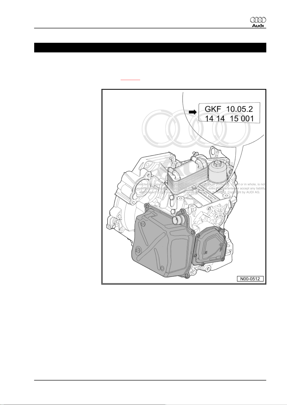
1 Gearbox identification
The “6-speed direct shift gearbox 02E (four-wheel drive)” is in‐
stalled in the Audi TT 1999 ▸. Allocation ⇒ page 2 .
Audi TT 1999 ➤
The gearbox code is located on the top of the gearbox, near the
oil cooler.
Example of a gearbox:
♦ GKF = gearbox code
♦ 10.05.2 = date of production: 10th May 2002
The code letters of the gearbox are also given on the vehicle data
stickers.
1. Gearbox identification 1
Page 6
Protected by copyright. Copying for private or commercial purposes, in part or in whole, is not
permitted unless authorised by AUDI AG. AUDI AG does not guarantee or accept any liability
with respect to the correctness of information in this document. Copyright by AUDI AG.
Audi TT 1999 ➤
Direct shift gearbox 02E, four-wheel drive - Edition 12.2006
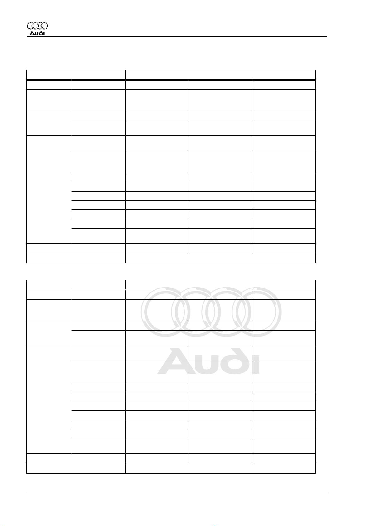
2 Code letters, gearbox allocation, ratios, equipment
Direct shift gearbox 02E four-wheel drive
Gearbox Code letters GVF GVG GYU
Allocation Model
Ratios Final drive I
Z2 : Z
1
Overall ratio i
Allocation: rear final drive Designation: 02D
Manufac‐
tured
fro
m
03.03 03.03 07.03
to
Engine
Audi TT 1999 ▸ Audi TT 1999 ▸ Audi TT 1999 ▸
3.2 ltr. - 184 kW
6 cylinders
3.2 ltr. - 184 kW
6 cylinders
3.2 ltr. - 184 kW
6 cylinders
69 : 17 = 4.059 69 : 17 = 4.059 69 : 17 = 4.059
for 1st to 4th gear
Final drive II
69 : 22 = 3.136 69 : 22 = 3.136 69 : 22 = 3.136
for 5th/6th gear
and reverse gear
1st gear
2nd gear
3rd gear
4th gear
5th gear
6th gear
Reverse
gear
in top gear 2.889 2.889 2.889
ov.
45 : 13 = 3.462 45 : 13 = 3.462 45 : 13 = 3.462
45 : 22 = 2.045 45 : 22 = 2.045 45 : 22 = 2.045
45 : 31 = 1.452 45 : 31 = 1.452 45 : 31 = 1.452
41 : 38 = 1.079 41 : 38 = 1.079 41 : 38 = 1.079
39 : 35 = 1.114 39 : 35 = 1.114 39 : 35 = 1.114
35 : 38 = 0.921 35 : 38 = 0.921 35 : 38 = 0.921
22 : 14 x 33 : 13 =
3.989
22 : 14 x 33 : 13 =
3.989
22 : 14 x 33 : 13 =
05.04
3.989
Direct shift gearbox 02E four-wheel drive
Gearbox Code letters GYV GYW HAH
Manufac‐
tured
fro
m
03.03 07.03
03.04
06.04
10.05
to
Allocation Model
Engine
Ratios Final drive I
Audi TT 1999 ▸ Audi TT 1999 ▸ Audi TT 1999 ▸
3.2 ltr. - 184 kW
6 cylinders
3.2 ltr. - 184 kW
6 cylinders
3.2 ltr. - 184 kW
6 cylinders
69 : 17 = 4.059 69 : 17 = 4.059 69 : 17 = 4.059
for 1st to 4th gear
Z2 : Z
1
Final drive II
69 : 22 = 3.136 69 : 22 = 3.136 69 : 22 = 3.136
for 5th/6th gear
Overall ratio i
and reverse gear
1st gear
2nd gear
3rd gear
4th gear
5th gear
6th gear
Reverse
gear
in top gear 2.889 2.889 2.889
ov.
45 : 13 = 3.462 45 : 13 = 3.462 45 : 13 = 3.462
45 : 22 = 2.045 45 : 22 = 2.045 45 : 22 = 2.045
45 : 31 = 1.452 45 : 31 = 1.452 41 : 28 = 1.464
41 : 38 = 1.079 41 : 38 = 1.079 41 : 38 = 1.079
39 : 35 = 1.114 39 : 35 = 1.114 35 : 32 = 1.094
35 : 38 = 0.921 35 : 38 = 0.921 35 : 38 = 0.921
22 : 14 x 33 : 13 =
3.989
22 : 14 x 33 : 13 =
3.989
22 : 14 x 33 : 13 =
3.989
Allocation: rear final drive Designation: 02D
2 Rep. Gr.00 - Technical data
Page 7
Protected by copyright. Copying for private or commercial purposes, in part or in whole, is not
permitted unless authorised by AUDI AG. AUDI AG does not guarantee or accept any liability
with respect to the correctness of information in this document. Copyright by AUDI AG.
Direct shift gearbox 02E, four-wheel drive - Edition 12.2006
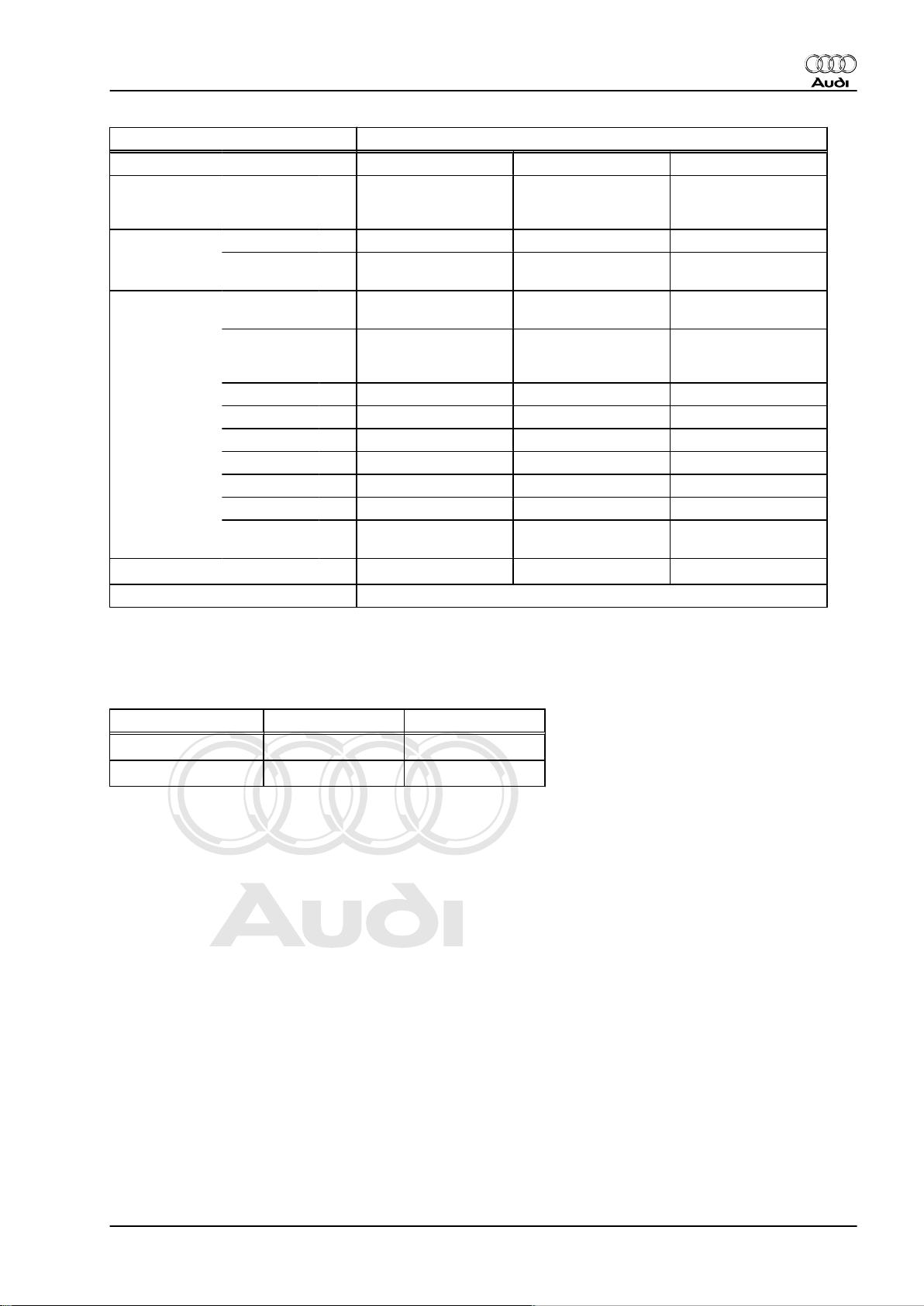
Direct shift gearbox 02E four-wheel drive
Gearbox Code letters HQB
Manufac‐
tured
fro
m
11.05
to
Allocation Model
Engine
Audi TT 1999 ▸
3.2 ltr. - 184 kW
6 cylinders
Ratios Final drive I
69 : 17 = 4.059
for 1st to 4th gear
Z2 : Z
1
Final drive II
69 : 22 = 3.136
for 5th/6th gear
and reverse gear
Overall ratio i
1st gear
2nd gear
3rd gear
4th gear
5th gear
6th gear
Reverse
gear
in top gear 2.889
ov.
45 : 13 = 3.462
45 : 22 = 2.045
41 : 28 = 1.464
41 : 38 = 1.079
35 : 32 = 1.094
35 : 38 = 0.921
22 : 14 x 33 : 13 =
3.989
Allocation: rear final drive Designation: 02D
Audi TT 1999 ➤
2.1 Calculating ratio “i”
Example:
Drive gear ZG1 = 38 ZA1 = 22
Driven gear ZG2 = 35 ZA2 = 69
i = Z2 : Z1 (Z1 = number of teeth on drive gear, Z2 = number of
teeth on driven gear)
iG = gear ratio = ZG2 : ZG1 = 35 : 38 = 0.92
iA = axle ratio = ZA2 : ZA1 = 69 : 22 = 3.136
iov = overall ratio = iG x iA = 0.92 x 3.136 = 2.89
6th gear Final drive
2. Code letters, gearbox allocation, ratios, equipment 3
Page 8
Protected by copyright. Copying for private or commercial purposes, in part or in whole, is not
permitted unless authorised by AUDI AG. AUDI AG does not guarantee or accept any liability
with respect to the correctness of information in this document. Copyright by AUDI AG.
Audi TT 1999 ➤
Direct shift gearbox 02E, four-wheel drive - Edition 12.2006
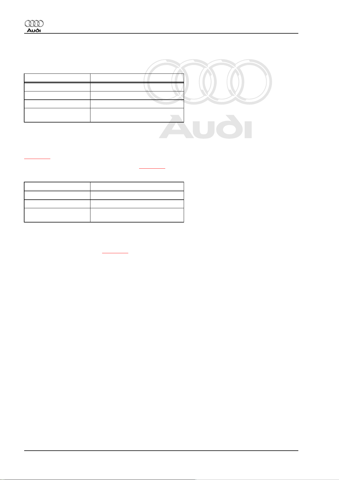
3 Capacities
Gearbox capacity
Capacities Direct shift gearbox 02E
Initial filling 6.9 ltr.
Oil change approx. 5.5 ltr.
Change interval ⇒ Maintenance tables
Lubricant, specification Gear oil for direct shift gearbox 02E
Part No.: ⇒ Parts catalogue
Only the gear oil available as a replacement part may be used for
the direct shift gearbox 02E. Other types of oil cause malfunctions
and/or failure of the gearbox.
When changing gear oil always renew the gear oil filter
⇒ page 86 .
Checking gear oil level and changing gear oil ⇒ page 74 .
Bevel box capacity
Capacities Bevel box
Initial filling 0.9 ltr.
Oil change Filled for life, no change
Lubricant For gear oil refer to ⇒ Parts cata‐
logue
Only the gear oil available as a replacement part may be used for
the bevel box. Other oils cause faults and/or failure of the bevel
box.
Checking oil level in bevel box ⇒ page 94 .
4 Rep. Gr.00 - Technical data
Page 9
Protected by copyright. Copying for private or commercial purposes, in part or in whole, is not
permitted unless authorised by AUDI AG. AUDI AG does not guarantee or accept any liability
with respect to the correctness of information in this document. Copyright by AUDI AG.
Direct shift gearbox 02E, four-wheel drive - Edition 12.2006
4 Safety precautions
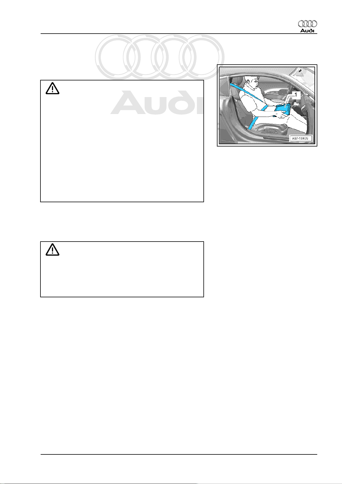
Observe the following precautions if test and measuring instru‐
ments are required during a test drive:
WARNING
Accidents can be caused if the driver is distracted by test
equipment or if test equipment is not secured.
Injuries can also be caused if the passenger's airbag is trig‐
gered in a collision.
• The use of test equipment while driving causes distraction.
• There is an increased risk of injury if test equipment is not
secured.
♦ Move the passenger's seat to the rearmost position.
♦ Use only vehicle diagnosis and service information sys‐
tem -VAS 5052- or diagnosis system -VAS 5053- .
♦ Test equipment may only be operated by the passenger;
the tester -1- must be placed flat on the passenger's lap
as illustrated.
Audi TT 1999 ➤
Observe the following precautions to avoid possible injury and/or
the destruction of electrical and electronic components:
♦ Switch off ignition before disconnecting and connecting test
equipment.
Caution
♦ Follow steps required when disconnecting battery ⇒ Elec‐
trical system; Rep. Gr. 27 .
♦ Always switch off ignition before disconnecting or con‐
necting the battery to ensure gearbox control unit is not
damaged.
4. Safety precautions 5
Page 10

Protected by copyright. Copying for private or commercial purposes, in part or in whole, is not
permitted unless authorised by AUDI AG. AUDI AG does not guarantee or accept any liability
with respect to the correctness of information in this document. Copyright by AUDI AG.
Audi TT 1999 ➤
Direct shift gearbox 02E, four-wheel drive - Edition 12.2006
5 Notes on the direct shift gearbox 02E
5.1 General notes
Gearbox
The direct shift gearbox 02E is also referred to as a dual-clutch
gearbox. The engine torque is transferred to the gearbox via the
dual-mass flywheel. The layout of the gearbox is basically similar
to that of a 6-speed manual gearbox. The two multi-plate "wet"
clutches are regulated hydraulically and actuated alternately so
that the gearbox is operated like an automatic gearbox, i.e. the
gears are engaged automatically (or manually via the tiptronic
function). There is no clutch pedal. For further information please
refer to ⇒ Self-study programme No. 308 ; Direct shift
gearbox 02E .
Selector mechanism
The selector lever position is no longer transmitted mechanically
via the selector lever cable and multi-function switch (driving
range sensor) as on the automatic gearbox. The selector lever
positions and gear changes are transmitted to the gearbox control
unit by a separate selector mechanism control unit via CAN bus.
This means that gear shifts are effected without a cable. Excep‐
tion: In selector lever position “P” the selector lever cable is used
to mechanically engage the parking lock.
Gear oil
The gear oil level in gearbox and final drive (front) is checked and
topped up together ⇒ page 74 .
♦ Only the oil available as a replacement part may be used in
the direct shift gearbox 02E. Other types of oil will cause mal‐
functions and/or failure of the gearbox; for Part No. refer to
⇒ page 4 .
The oil level in the bevel box is checked and topped up separately
⇒ page 94 .
♦ Only the gear oil available as a replacement part may be used
for the bevel box. Other oils cause faults and/or failure of the
bevel box.
Regulations for the disposal of oil
Make sure that used oil is taken to the appropriate collection cen‐
tre for recycling.
♦ Improper disposal of used oil endangers the environment.
♦ It is forbidden to add solvents, brake fluid, coolant or similar.
♦ Please observe the information shown on the packaging of the
oil.
Variation of gear-change points for gradients
An additional gear change map automatically selects gear
changes for gradients depending on accelerator pedal position
and driving speed.
• Gear change map for extreme uphill gradients is matched to
engine output
• Gear change map for extreme downhill gradients is matched
to the braking effect of the engine
• Increased engine braking effect can also be obtained by di‐
rectly selecting a specific gear via the tiptronic function, e.g.
when towing a trailer on downhill gradients.
6 Rep. Gr.00 - Technical data
Page 11

Protected by copyright. Copying for private or commercial purposes, in part or in whole, is not
permitted unless authorised by AUDI AG. AUDI AG does not guarantee or accept any liability
with respect to the correctness of information in this document. Copyright by AUDI AG.
Direct shift gearbox 02E, four-wheel drive - Edition 12.2006
5.2 Safety functions of gearbox control unit
In the event of a failure of one or more components/sensors, the
gearbox control unit will activate appropriate backup functions.
This ensures that the gearbox will not be damaged, however, the
function and quality of the gear shifts will be impaired.
Faults detected by the gearbox are classified in four different cat‐
egories.
♦ 1) The fault is stored and a backup programme enables the
vehicle to drive on (in some cases with restrictions). The driver
will not be made aware of the problem, as it is not critical to
driving safety or to the gearbox itself. The gear selection indi‐
cator in the instrument cluster will continue to show the selec‐
tor lever position currently engaged in the normal way. If at all,
the driver will only notice the fault if he experiences driveability
problems, and will then automatically contact an Audi Service
Partner to identify the cause.
♦ 2) Certain positions on the gear selection indicator in the in‐
strument cluster start to flash. This is to inform the driver that
this particular selector lever position is currently not available.
Example: position “D” is not available when selector lever is in
position “R” and vehicle is still rolling backwards. In this case,
selector lever position “D” will start to flash on the gear selec‐
tion indicator in the instrument cluster. The gearbox control
unit prevents the 1st gear from being engaged in order to avoid
damage to the gearbox. 1st gear will be engaged once the
vehicle has come to a standstill.
♦ 3) The complete gear selection indicator in the instrument
cluster is lit up and flashing. The current selector lever position
is indicated in the instrument cluster (e.g. “D” is highlighted).
This is an indication that the gearbox has been overloaded or
the maximum temperature in the gearbox has been exceeded
(overheating), e.g. towing a load that was too heavy.
♦ 4) If the complete gear selection indicator in the instrument
cluster is lit up and flashing, this means that a serious fault in
the gearbox has been identified. The display in the instrument
cluster no longer shows the current selector lever position. The
defect is critical with regard to driving safety or the gearbox
itself. It may no longer be possible to use all gears. The driver
is made aware by the flashing gear selection indicator that he
should immediately contact an Audi Service Partner.
Audi TT 1999 ➤
5. Notes on the direct shift gearbox 02E 7
Page 12
Protected by copyright. Copying for private or commercial purposes, in part or in whole, is not
permitted unless authorised by AUDI AG. AUDI AG does not guarantee or accept any liability
with respect to the correctness of information in this document. Copyright by AUDI AG.
Audi TT 1999 ➤
Direct shift gearbox 02E, four-wheel drive - Edition 12.2006
6 Notes on tow-starting and towing
WARNING
If the vehicle has to be towed, the selector lever must be set to
position N and the vehicle must not to be towed further than
50 km or at a speed in excess of 50 km/h, as the gearbox would
otherwise suffer irreparable damage.
Note
It is not possible to start the engine by means of tow-starting, for
instance in the case of insufficient battery charge or if the starter
is not working.
8 Rep. Gr.00 - Technical data
Page 13

Protected by copyright. Copying for private or commercial purposes, in part or in whole, is not
permitted unless authorised by AUDI AG. AUDI AG does not guarantee or accept any liability
with respect to the correctness of information in this document. Copyright by AUDI AG.
Direct shift gearbox 02E, four-wheel drive - Edition 12.2006
7 Repair instructions
7.1 Contact corrosion!
Contact corrosion can occur if non-approved fasteners are used
on the vehicle (bolts, nuts, washers etc.).
For this reason, only fasteners with a special surface coating are
fitted.
Rubber or plastic parts and adhesives also consist of non-con‐
ductive materials.
If you are not sure whether used parts can be re-installed, always
fit new parts ⇒ Parts catalogue .
Please note:
♦ Use only genuine spare parts: these have been fully tested
and are compatible with aluminium.
♦ We recommend the use of accessories approved by Audi.
♦ Damage resulting from contact corrosion is not covered by the
warranty.
Audi TT 1999 ➤
7.2 General notes
Proper tools and the maximum possible care and cleanliness are
essential for satisfactory gearbox repairs. The usual basic safety
precautions also naturally apply when carrying out repair work.
To avoid repetition, a number of generally applicable instructions
for the various repair procedures are summarised here. They ap‐
ply to the work described in this Manual.
7. Repair instructions 9
Page 14
Protected by copyright. Copying for private or commercial purposes, in part or in whole, is not
permitted unless authorised by AUDI AG. AUDI AG does not guarantee or accept any liability
with respect to the correctness of information in this document. Copyright by AUDI AG.
Audi TT 1999 ➤
Direct shift gearbox 02E, four-wheel drive - Edition 12.2006
Guided fault finding, vehicle self-diagnosis and testing system
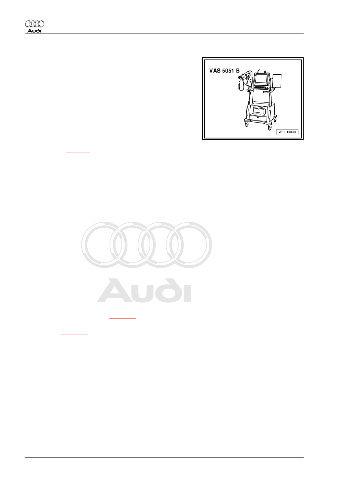
♦ Before servicing the gearbox, the exact cause of the failure
must be determined using the functions “Guided Fault Find‐
ing”, “Vehicle Self-diagnosis” and “Test Instruments” ⇒ Vehicle
diagnosis, testing and information system VAS 5051.
Special tools
For a complete list of special tools used in this Workshop Manual
⇒ "Special tools, Workshop equipment"
Gearbox
♦ Do not run the engine or tow the vehicle with the oil pan re‐
moved or when there is no gear oil in the gearbox.
♦ When renewing the gearbox the gear oil ⇒ page 74 must be
checked and topped up, if necessary. Filling quantities and
specification ⇒ page 4 .
♦ Thoroughly clean all joints and surrounding areas before dis‐
mantling.
♦ When installing gearbox, ensure that dowel sleeves are fitted
correctly.
O-rings, oil seals and gaskets
♦ Always renew O-rings, oil seals and gaskets.
♦ After removing gaskets and seals, always inspect the contact
surface on the housing or shaft for burrs resulting from removal
or for other signs of damage.
♦ Always replace paper gaskets. Completely remove old gasket
and clean sealing surfaces thoroughly.
♦ Lightly lubricate the outer circumference and sealing lip of oil
seals with gear oil before installing.
♦ Lightly lubricate O-rings with gear oil or vaseline before instal‐
lation to prevent them from getting crushed during assembly.
♦ Do not use any other lubricants where gear oil is used. Oth‐
erwise, there is a risk of problems occurring in the gearbox
hydraulics.
♦ The open side of the oil seals faces toward the side with fluid
filling.
♦ Observe rules for cleanliness ⇒ page 12 .
♦ After installing, check gear oil level, adjust to correct level if
necessary ⇒ page 74 .
Locking elements
♦ Do not overstretch circlips; renew if necessary.
♦ Circlips must be properly seated in the base of the groove.
Nuts, bolts
♦ Loosen bolts in reverse sequence to the specified tightening
sequence.
♦ Nuts and bolts which secure covers and housings should be
loosened and tightened in diagonal sequence and in stages if
no tightening sequence is specified.
♦ Renew self-locking nuts.
♦ Use a wire brush to clean the threads of bolts which are se‐
cured with locking fluid. Then apply locking fluid AMV 185 101 A1- to bolt threads before installing.
10 Rep. Gr.00 - Technical data
Page 15

Protected by copyright. Copying for private or commercial purposes, in part or in whole, is not
permitted unless authorised by AUDI AG. AUDI AG does not guarantee or accept any liability
with respect to the correctness of information in this document. Copyright by AUDI AG.
Direct shift gearbox 02E, four-wheel drive - Edition 12.2006
♦ The tightening torques stated apply to non-oiled nuts and
bolts.
Audi TT 1999 ➤
7. Repair instructions 11
Page 16

Protected by copyright. Copying for private or commercial purposes, in part or in whole, is not
permitted unless authorised by AUDI AG. AUDI AG does not guarantee or accept any liability
with respect to the correctness of information in this document. Copyright by AUDI AG.
Audi TT 1999 ➤
Direct shift gearbox 02E, four-wheel drive - Edition 12.2006
8 Rules for cleanliness when working
on the gearbox
♦ Thoroughly clean all joints and surrounding areas before dis‐
mantling.
♦ Place removed parts on a clean surface and cover them over.
Use sheeting and paper. Use lint-free cloths.
♦ Carefully cover or seal open components if repairs cannot be
carried out immediately.
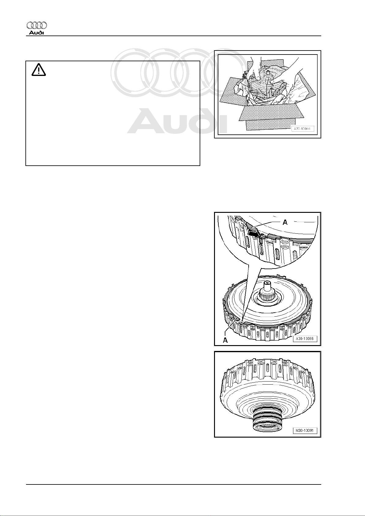
♦ Only install clean components: do not remove replacement
parts from packaging until just before installation.
♦ Always renew O-rings, oil seals and gaskets.
♦ Always replace paper gaskets. Completely remove old gasket
and clean sealing surfaces thoroughly.
♦ Use a wire brush to clean the threads of bolts which are se‐
cured with locking fluid. Then apply locking fluid AMV 185 101 A1- to bolt threads before installing.
12 Rep. Gr.00 - Technical data
Page 17
Protected by copyright. Copying for private or commercial purposes, in part or in whole, is not
permitted unless authorised by AUDI AG. AUDI AG does not guarantee or accept any liability
with respect to the correctness of information in this document. Copyright by AUDI AG.
Audi TT 1999 ➤
Direct shift gearbox 02E, four-wheel drive - Edition 12.2006
30 – Clutch
1 Servicing multiple clutch
♦ The clutch in the direct shift gearbox 02E consists of two sets
of plates, and is therefore referred to as a “multiple clutch”. The
larger set of plates (located on the outside) is designated
“K 1” (clutch 1), and controls the torque flow for reverse gear
and gears “1”, “3” and “5”. The smaller set of plates (on the
inside) is designated “K 2” (clutch 2), and controls the torque
flow for gears “2”, “4” and “6”.
♦ Any work performed on the multiple clutch requires extra care:
all the parts are balanced and matched together in production.
If the components are rotated out of their original positions
when repairing, this will cause imbalance and impair the
smoothness of the gearchanges and reduce the service life of
the unit.
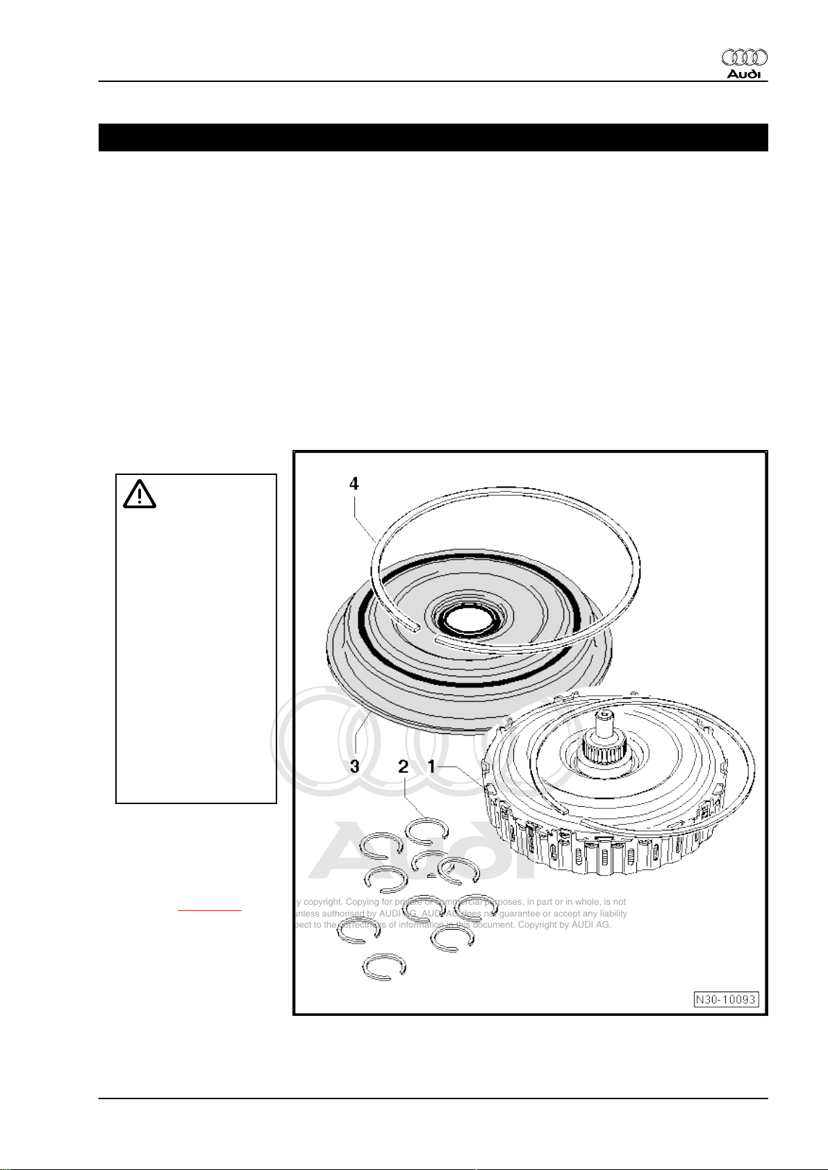
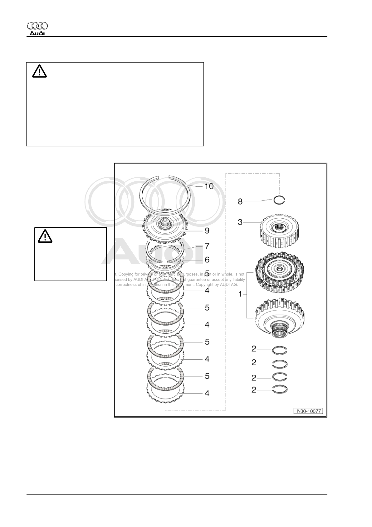
1.1 Multiple clutch - exploded view of components (replacement parts)
1 - Multiple clutch with circlip
Caution
♦The drive plate (top sec‐
tion of multiple clutch) of
a new clutch is not se‐
cured with the circlip, it is
only a “close fit” in the
clutch.
♦The drive plate must re‐
main engaged between
the splines of the outer
plate carrier.
♦If the drive plate comes
loose, the clutch plates
can slip out of position in‐
side the multiple clutch
unit. If this happens, it
may not be possible to
adjust the multiple clutch
correctly during installa‐
tion.
2 - Circlip
❑ 10 x, with different thick‐
nesses for adjusting
❑ Determine circlip thick‐
ness when installing
clutch ⇒ page 20
3 - Clutch end cover
4 - Circlip for clutch end cover
1. Servicing multiple clutch 13
Page 18
Protected by copyright. Copying for private or commercial purposes, in part or in whole, is not
permitted unless authorised by AUDI AG. AUDI AG does not guarantee or accept any liability
with respect to the correctness of information in this document. Copyright by AUDI AG.
Audi TT 1999 ➤
Direct shift gearbox 02E, four-wheel drive - Edition 12.2006
Dismantled multiple clutch - exploded view of components
Caution
♦ This illustration serves only as an overview of compo‐
nents; at the present time the multiple clutch must NOT be
dismantled, as all outer and inner plates are matched and
balanced before installation.
♦ If the drive plate is loosened, the plates can slip out of
position inside the multiple clutch unit. If this happens, it
may not be possible to adjust the multiple clutch correctly
during installation.
1 - Multiple clutch/clutch hous‐
ing
❑ Outer plate carrier
2 - Oil seals
❑ 4x
3 - Inner plate carrier
❑ Do not remove
Caution
DO NOT remove or lift up
the inner plate carrier.
This could cause the
plates to move out of
their original positions.
4 - Outer plates
❑ 4x
5 - Inner plates
❑ 4x
6 - Thrust washer
7 - Circlip
❑ Fit a new circlip of the
same thickness if the
original circlip is re‐
moved in order to re-in‐
stall the clutch plates.
8 - Circlip
❑ Re-determine thickness
when installing a new
clutch ⇒ page 20
9 - Drive plate
10 - Circlip
❑ Renew
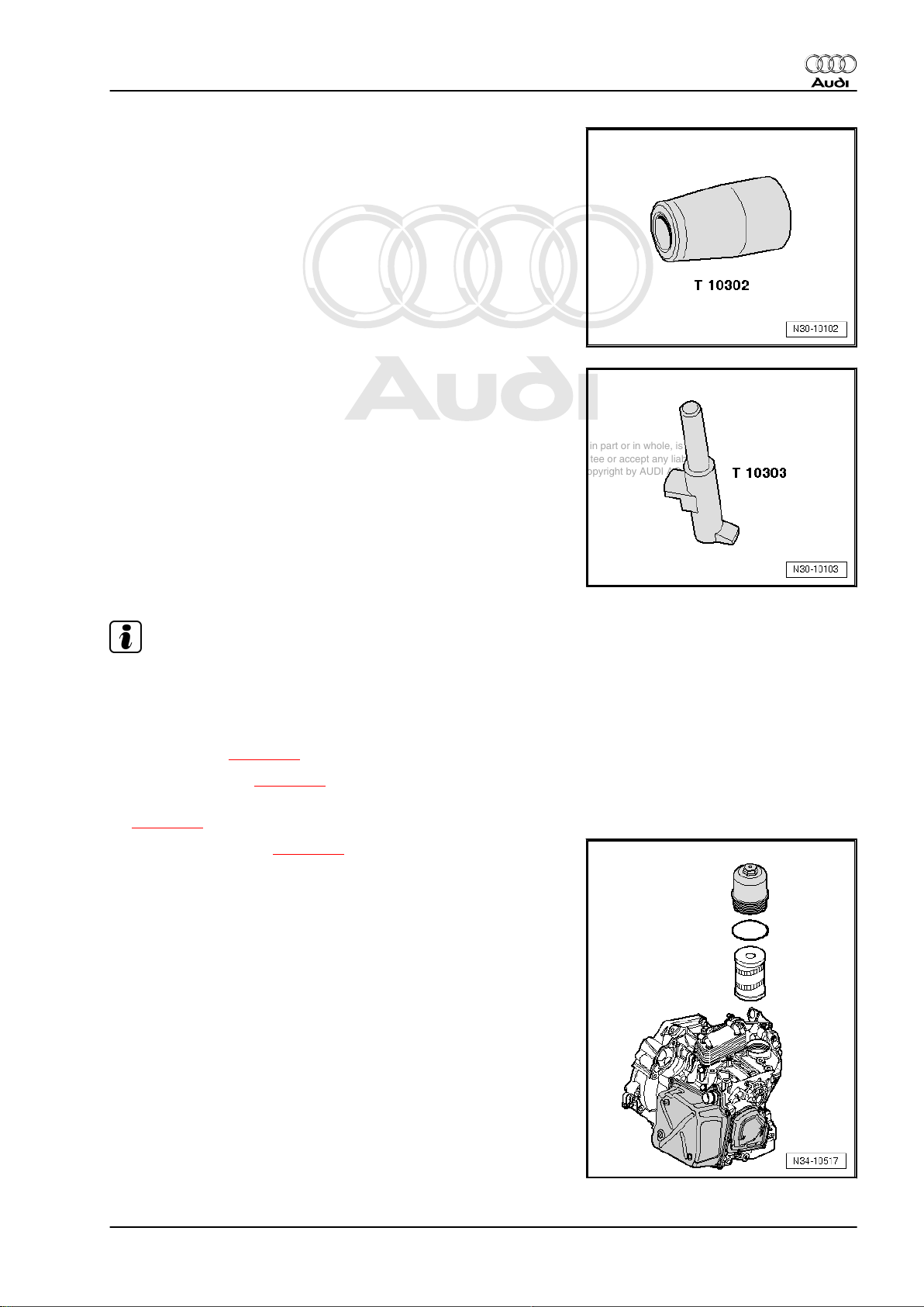
1.2 Removing and installing multiple clutch
Special tools and workshop equipment required
14 Rep. Gr.30 - Clutch
Page 19
Protected by copyright. Copying for private or commercial purposes, in part or in whole, is not
permitted unless authorised by AUDI AG. AUDI AG does not guarantee or accept any liability
with respect to the correctness of information in this document. Copyright by AUDI AG.
♦ Assembly sleeve -T10302-
♦ Retaining pin -T10303-
Audi TT 1999 ➤
Direct shift gearbox 02E, four-wheel drive - Edition 12.2006
Note
Assembly sleeve -T10302- must be cleaned before use; do not
use an assembly sleeve if it is scratched.
Removing clutch end cover
– Drain gear oil ⇒ page 80 .
– Remove gearbox ⇒ page 61 .
– Secure gearbox to assembly stand in vertical position
⇒ page 72 .
– Renew gear oil filter ⇒ page 86 .
1. Servicing multiple clutch 15
Page 20
Protected by copyright. Copying for private or commercial purposes, in part or in whole, is not
permitted unless authorised by AUDI AG. AUDI AG does not guarantee or accept any liability
with respect to the correctness of information in this document. Copyright by AUDI AG.
Audi TT 1999 ➤
Direct shift gearbox 02E, four-wheel drive - Edition 12.2006
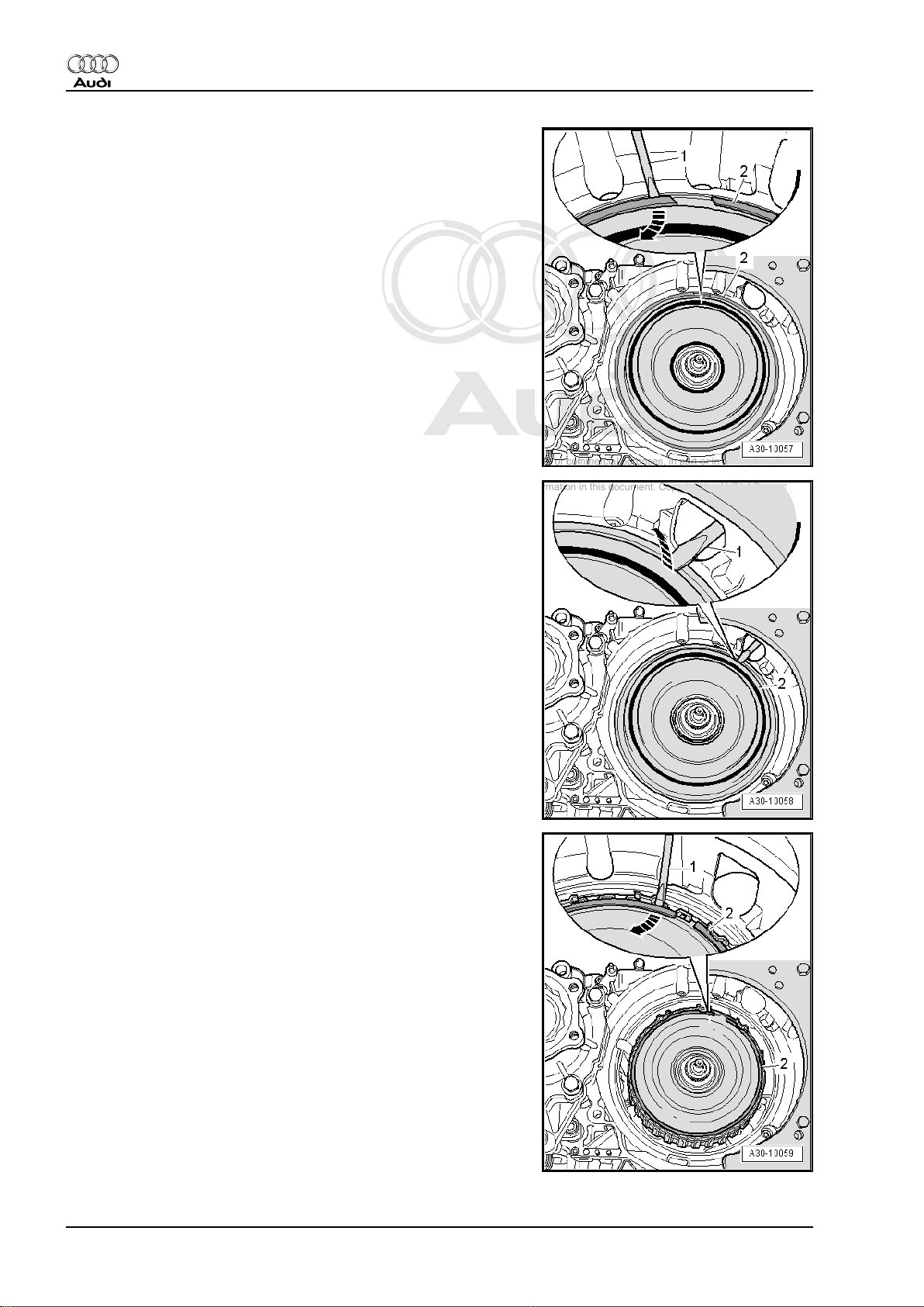
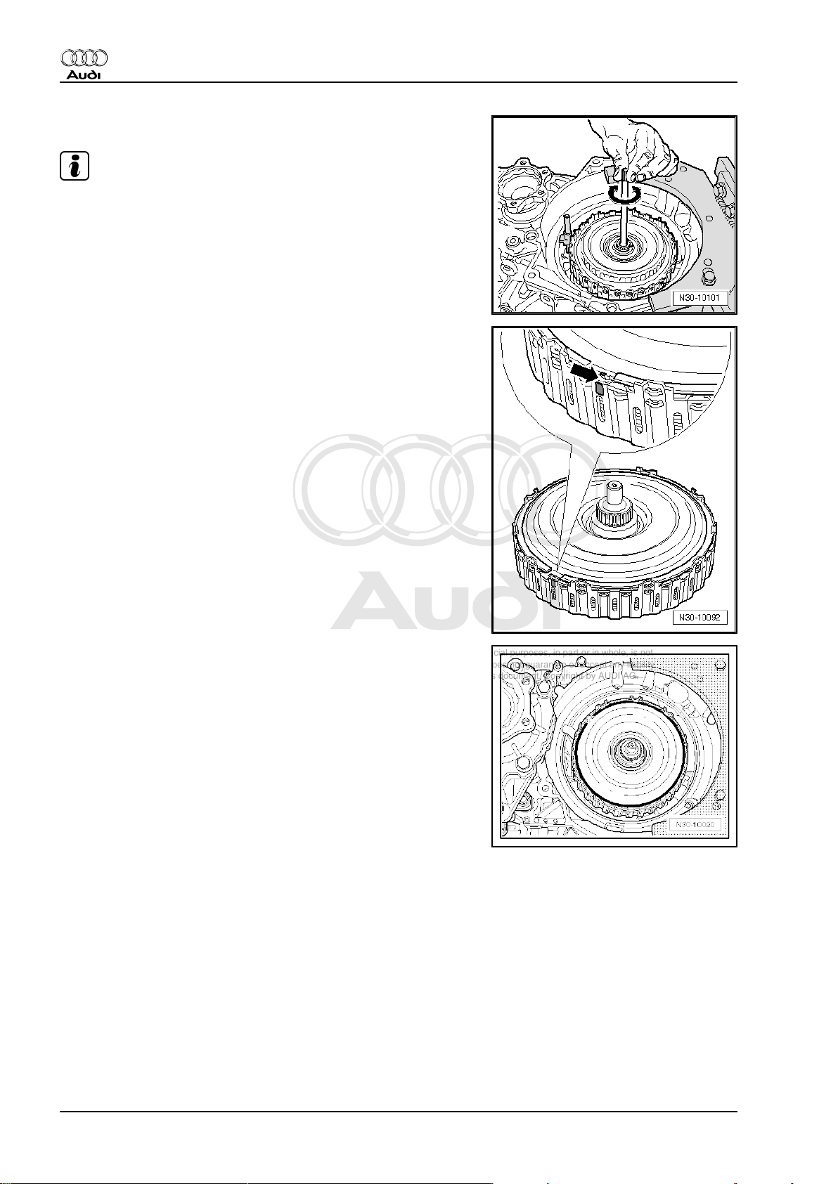
– Using a screwdriver -1-, pry out circlip -2- for clutch end cover
-arrow- and take out circlip.
– Working through opening for starter motor, pry off clutch end
cover -2- using a screwdriver -1- or suitable lever -arrow- and
take off clutch end cover.
Removing multiple clutch
– Pry out circlip -2- using a screwdriver -1- -arrow-.
16 Rep. Gr.30 - Clutch
Page 21
Protected by copyright. Copying for private or commercial purposes, in part or in whole, is not
permitted unless authorised by AUDI AG. AUDI AG does not guarantee or accept any liability
with respect to the correctness of information in this document. Copyright by AUDI AG.
Direct shift gearbox 02E, four-wheel drive - Edition 12.2006
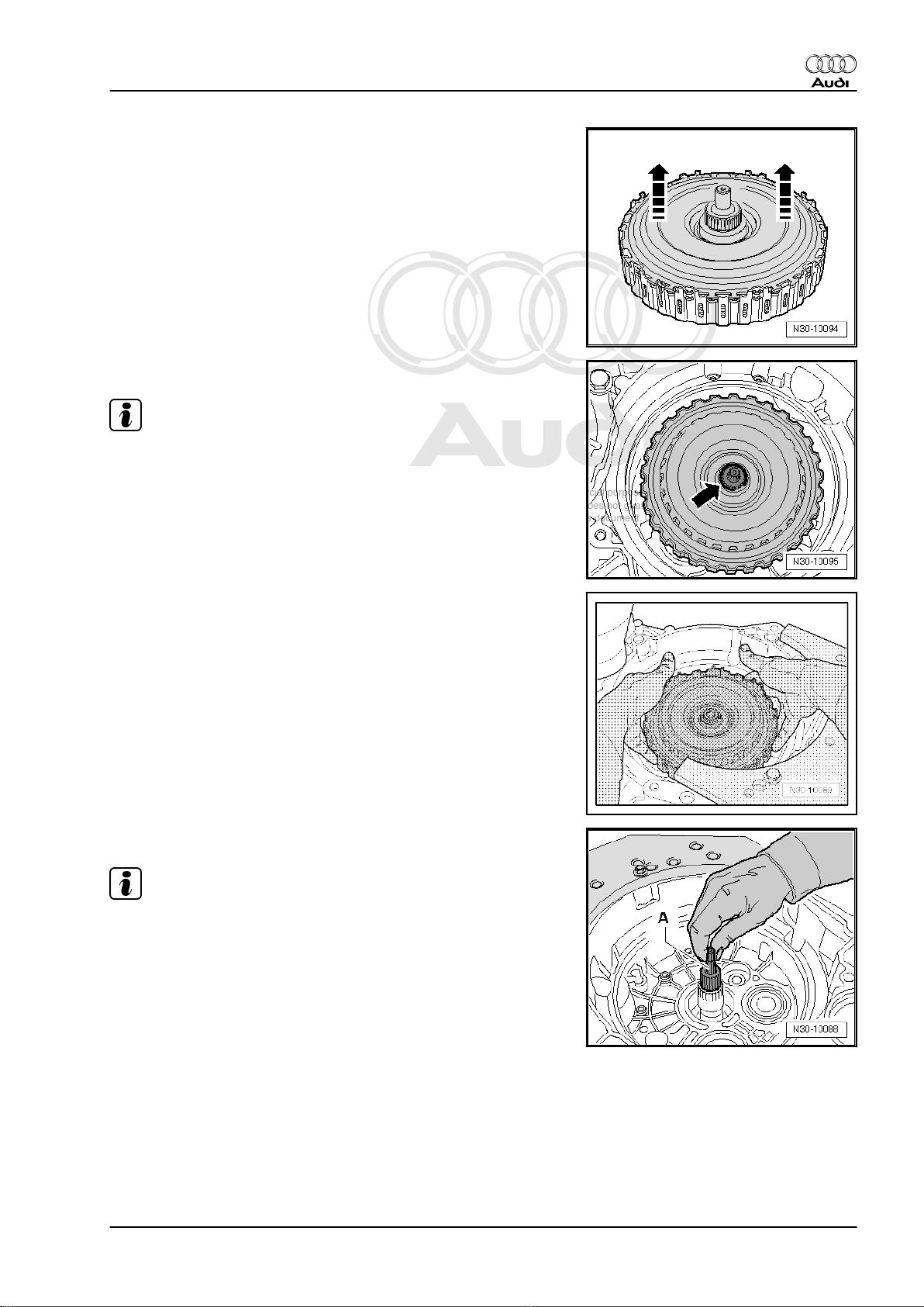
– Remove drive plate -arrows-.
– Use screwdriver or suitable pliers to pry out circlip -arrow-.
Note
This circlip must be replaced with a new circlip of the correct
thickness when re-assembling.
Audi TT 1999 ➤
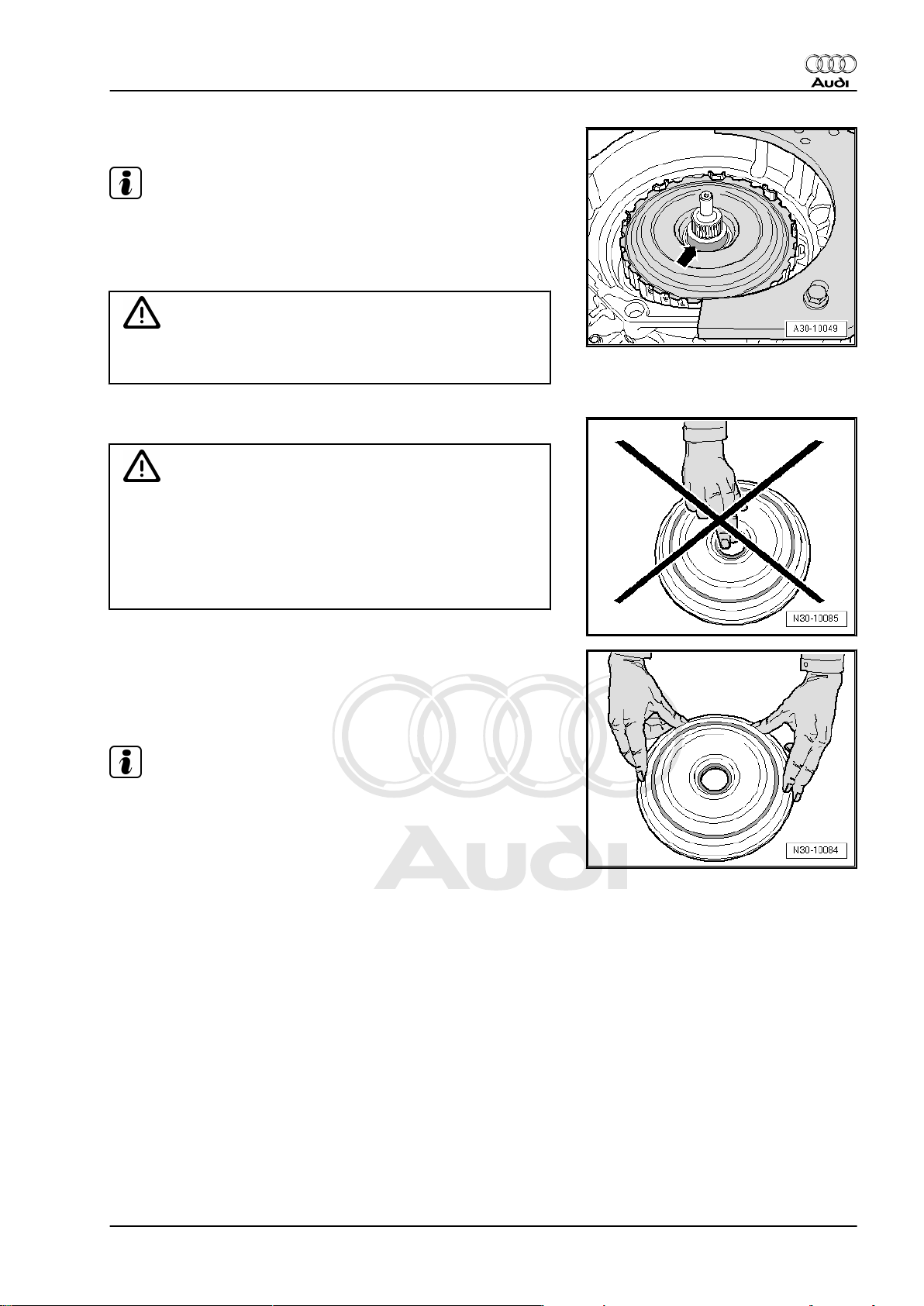
– Take out multiple clutch.
– After removing multiple clutch, check clutch bellhousing for
damage caused during removal.
– Pull out pump shaft -A-.
Note
The pump shaft is not re-installed until after the new clutch has
been fitted. Keep the shaft in a suitable place until it is required.
1. Servicing multiple clutch 17
Page 22
Protected by copyright. Copying for private or commercial purposes, in part or in whole, is not
permitted unless authorised by AUDI AG. AUDI AG does not guarantee or accept any liability
with respect to the correctness of information in this document. Copyright by AUDI AG.
Audi TT 1999 ➤
Direct shift gearbox 02E, four-wheel drive - Edition 12.2006
Installing multiple clutch
Caution
♦ The drive plate of a new clutch is not secured with a circlip;
it is only a “close fit” in the clutch.
♦ While carrying out the following steps you must therefore
hold the drive plate by pressing it into the outer plate car‐
rier with both thumbs.
♦ The drive plate must remain engaged between the splines
of the outer plate carrier.
♦ If the drive plate comes loose, the clutch plates can slip
out of position inside the multiple clutch unit. If this hap‐
pens, it may not be possible to adjust the multiple clutch
correctly during installation.
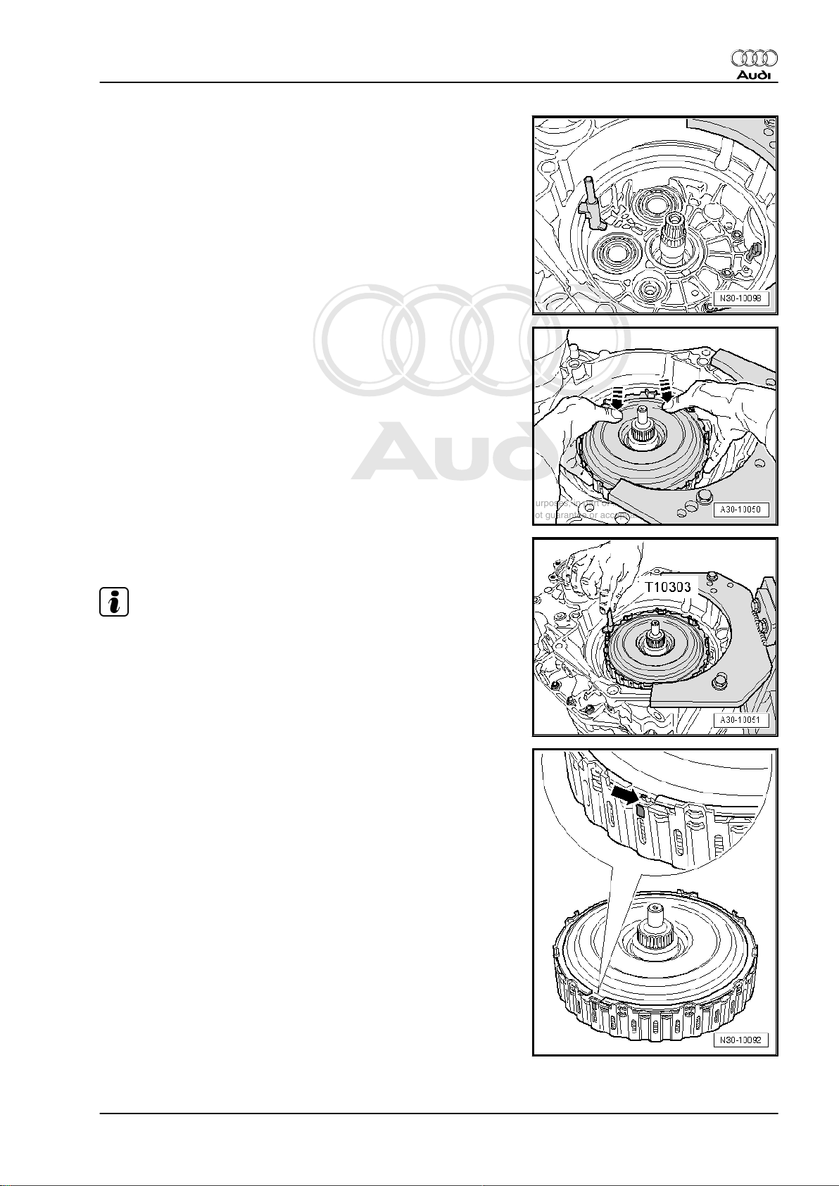
– Take the circlip out of the packaging.
– Take the clutch for direct shift gearbox out of the packaging,
at the same time pressing the drive plate into the outer plate
carrier with both thumbs.
– Secure drive plate in outer plate carrier with “old” circlip -A-
from removed clutch.
• Do NOT use the new circlip supplied when carrying out this
installation.
• The circlip must be installed so that the lug on the drive plate
-arrow- and the colour-marked splines on the outer plate car‐
rier are located between the two ends of the circlip.
• The circlip must be fully engaged all round.
– Check that the 4 oil seals on the hub on the underside of the
multiple clutch are correctly seated; engage in position if nec‐
essary.
• The joints of the seals should be offset and not aligned one
above the other.
18 Rep. Gr.30 - Clutch
Page 23
Protected by copyright. Copying for private or commercial purposes, in part or in whole, is not
permitted unless authorised by AUDI AG. AUDI AG does not guarantee or accept any liability
with respect to the correctness of information in this document. Copyright by AUDI AG.
Direct shift gearbox 02E, four-wheel drive - Edition 12.2006
– Apply retaining pin -T10303- to seat of clutch end cover as
illustrated.
– Install multiple clutch in clutch bell housing (turn and move up
and down as required); do not allow clutch to drop into place.
While doing this, keep the drive plate pressed into the outer
plate carrier with both thumbs -arrows-.
Audi TT 1999 ➤
• During this procedure the retaining pin -T10303- must be held
in place by a 2nd mechanic.
Note
♦
The retaining pin remains in position until the clutch end cover
is installed.
♦
The multiple clutch must not be turned from this point onwards,
as this would turn the retaining pin -T10303- out of position.
– Check whether the projecting lug -arrow- on the drive plate is
positioned between the colour-marked splines on the outer
plate carrier.
If no markings are provided:
– Mark position of projecting lug in relation to outer rim of outer
plate carrier with waterproof pen as illustrated.
1. Servicing multiple clutch 19
Page 24
Protected by copyright. Copying for private or commercial purposes, in part or in whole, is not
permitted unless authorised by AUDI AG. AUDI AG does not guarantee or accept any liability
with respect to the correctness of information in this document. Copyright by AUDI AG.
Audi TT 1999 ➤
Direct shift gearbox 02E, four-wheel drive - Edition 12.2006
• When re-assembling, the lug on the drive plate must be loca‐
ted again at this marked position.
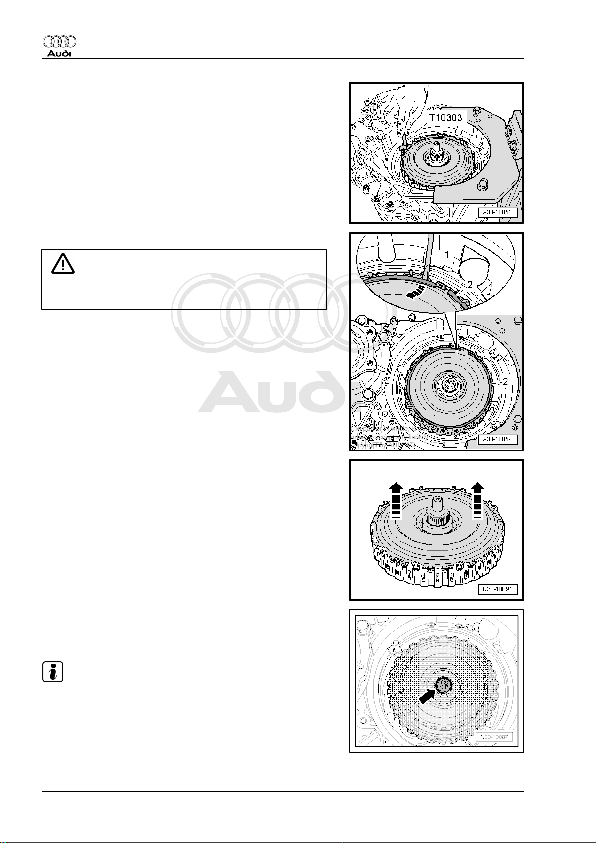
• While carrying out the following two steps the retaining pin T10303- must be held in place by a 2nd mechanic.
– Pry out the old circlip -2- using a screwdriver -1- -arrow-.
Caution
DO NOT remove or lift up the inner plate carrier. This could
cause the plates to move out of their original positions.
– After installing clutch, lift out drive plate -arrows-; if necessary
pry drive plate carefully out of splines on outer plate carrier
using a screwdriver.
– Lay drive plate aside.
Determining thickness of circlip for multiple clutch
– Select the 2 mm thick circlip from the circlips supplied with the
clutch and fit this circlip as shown -arrow-.
Note
This circlip is installed provisionally in order to measure the axial
play.
20 Rep. Gr.30 - Clutch
Page 25
Protected by copyright. Copying for private or commercial purposes, in part or in whole, is not
permitted unless authorised by AUDI AG. AUDI AG does not guarantee or accept any liability
with respect to the correctness of information in this document. Copyright by AUDI AG.
Direct shift gearbox 02E, four-wheel drive - Edition 12.2006
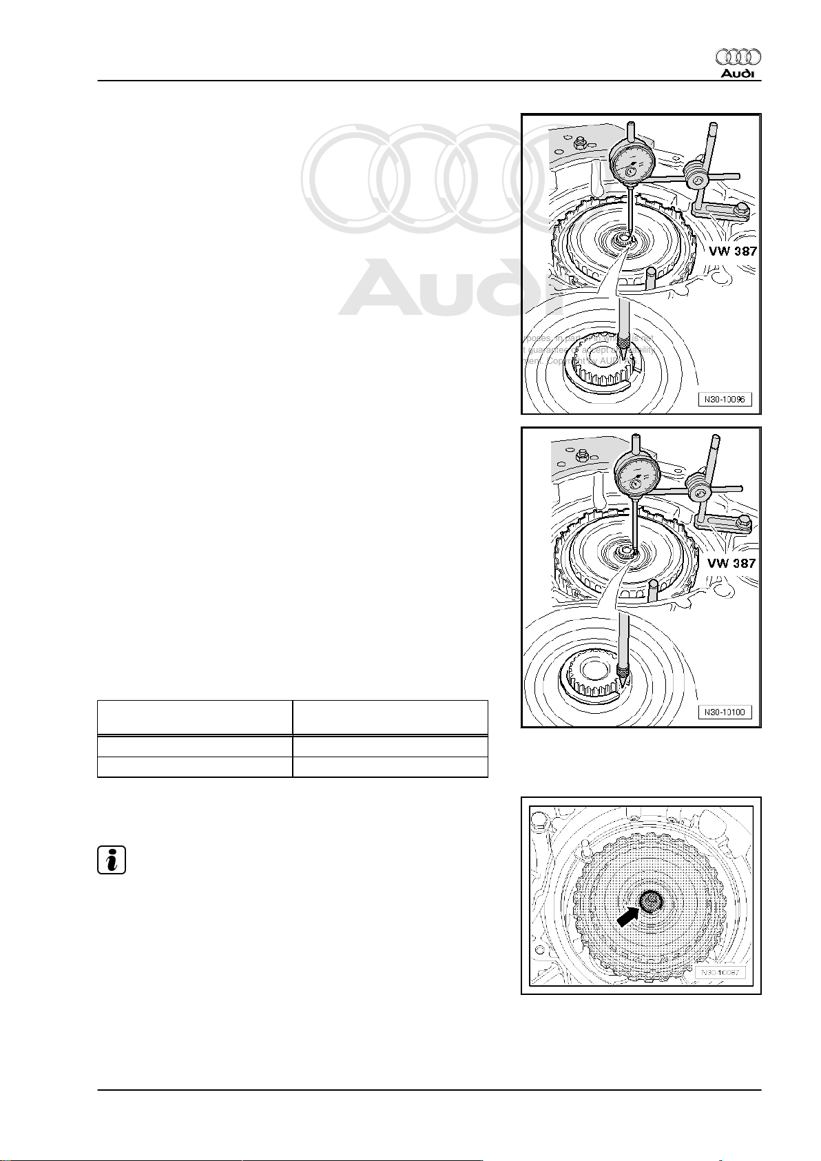
– Bolt universal dial gauge bracket -VW 387- onto gearbox
flange.
– For 1st measurement, apply tip of dial gauge to end of input
shaft as shown in illustration.
– Set dial gauge to “0” with a preload of 2 mm.
– Lift up clutch as far as it will go and note dial gauge reading (=
axial play of input shaft).
– For 2nd measurement, apply tip of dial gauge to hub of inner
plate carrier as shown in illustration.
• The tip of the dial gauge must not contact the circlip.
– Set dial gauge to “0” with a preload of 2 mm.
– Lift up clutch again as far as it will go and note dial gauge
reading.
The thickness of the new circlip is calculated according to the fol‐
lowing formula:
2nd measurement – 1st measurement + 1.85 mm = thickness
of circlip
The thickness of the new circlips -02E 311 321- is graduated in
steps of 0.1 mm. When selecting the required circlip, round up or
down to the nearest 10th of a millimetre as required. In other
words, values up to 0.049 are rounded down and values of 0.05
and above are rounded up.
Audi TT 1999 ➤
Calculated thickness of new cir‐
New circlip
clip
2.27 mm 2.3 mm
2.24 mm 2.2 mm
– Remove provisionally fitted circlip (2.0 mm) and fit new circlip
with thickness as calculated above.
Note
♦
If the calculated thickness of the new circlip is exactly 2.0 mm,
the circlip fitted previously for taking the measurement does
not have to be removed.
♦
All remaining circlips should be disposed of.
♦
Circlips may not be used more than once.
1. Servicing multiple clutch 21
Page 26
Protected by copyright. Copying for private or commercial purposes, in part or in whole, is not
permitted unless authorised by AUDI AG. AUDI AG does not guarantee or accept any liability
with respect to the correctness of information in this document. Copyright by AUDI AG.
Audi TT 1999 ➤
Direct shift gearbox 02E, four-wheel drive - Edition 12.2006
– Insert pump shaft.
Note
When installing, lift the shaft and turn it slightly -arrow- so that it
slides in and engages fully in the splines.
– Install drive plate in multiple clutch.
• The projecting lug on the drive plate must be positioned be‐
tween the colour-marked splines on the outer plate carrier.
Alternatively, align the new markings made earlier in this pro‐
cedure.
– Install new circlip securing drive plate.
• The circlip must be installed so that the lug on the drive plate
and the colour-marked splines on the outer plate carrier are
located between the two ends of the circlip.
• The circlip must be fully engaged all round.
– Use a screwdriver to check that the circlip is properly seated
and fully engaged.
– Take out retaining pin -T10303- between multiple clutch and
housing.
22 Rep. Gr.30 - Clutch
Page 27
Protected by copyright. Copying for private or commercial purposes, in part or in whole, is not
permitted unless authorised by AUDI AG. AUDI AG does not guarantee or accept any liability
with respect to the correctness of information in this document. Copyright by AUDI AG.
Direct shift gearbox 02E, four-wheel drive - Edition 12.2006
Installing clutch end cover
Note
Renew clutch end cover and circlip.
– Thoroughly degrease running surface -arrow- on drive plate
for oil seal of clutch end cover.
Caution
The contact surfaces of the clutch end cover must be cleaned
very thoroughly, otherwise leaks can occur.
– Clean contact surface for outer seal of clutch end cover.
Caution
♦ Do not touch the seal inside the opening in the clutch end
cover. This seal will only seal properly if the running sur‐
face is absolutely free of grease when installed.
Audi TT 1999 ➤
♦ Do not apply hammer blows directly to the clutch end cov‐
er. Any force applied to the inner part of the clutch end
cover will cause malfunctions.
– Take the new clutch end cover out of its packaging. Always
take hold of the outside of the clutch end cover, as illustrated.
DO NOT touch the seal inside the cover.
– Clean end of gearbox shaft if necessary.
Note
♦
Lightly lubricate the outer seal only.
♦
If there are any stickers on the inside or the outside of the end
cover, remove them thoroughly.
1. Servicing multiple clutch 23
Page 28
Protected by copyright. Copying for private or commercial purposes, in part or in whole, is not
permitted unless authorised by AUDI AG. AUDI AG does not guarantee or accept any liability
with respect to the correctness of information in this document. Copyright by AUDI AG.
Audi TT 1999 ➤
Direct shift gearbox 02E, four-wheel drive - Edition 12.2006
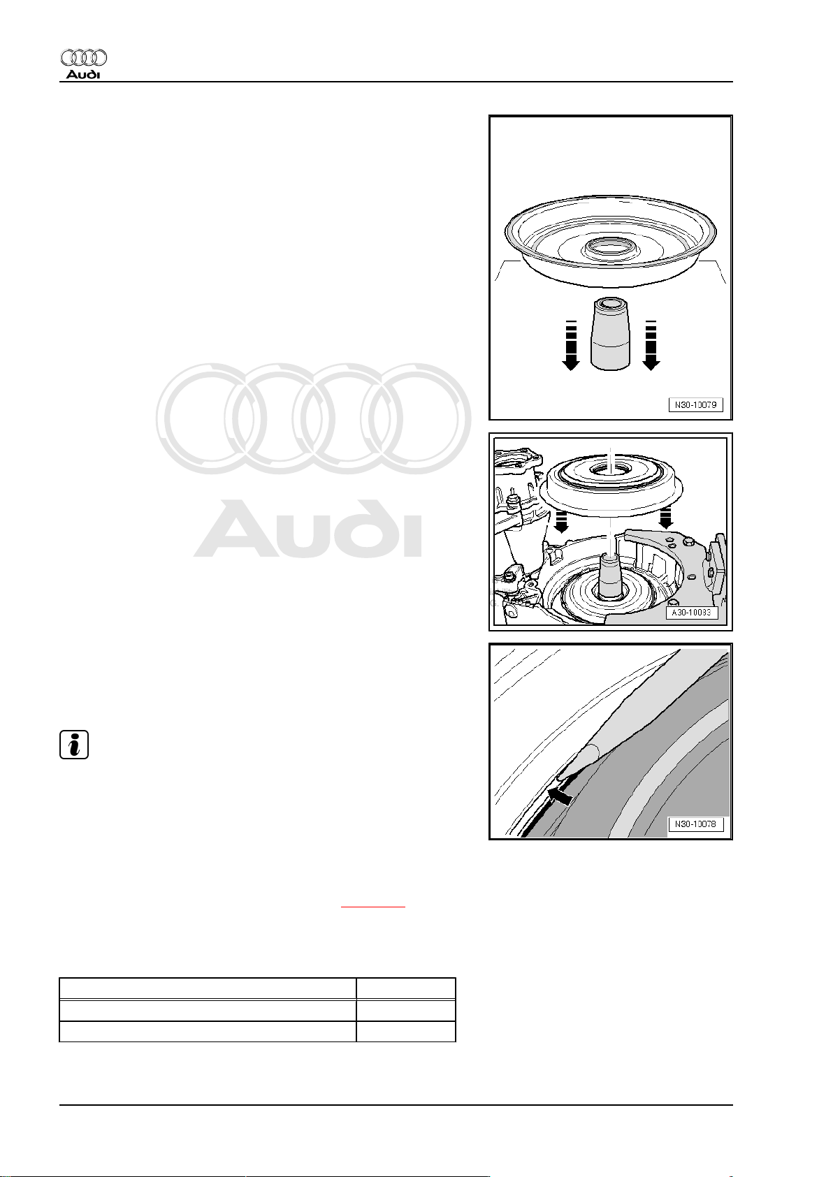
– Place assembly sleeve -T10302- on a flat surface.
– The seal in the centre of the clutch end cover must be pre-
formed before installation; this is done by guiding the new
clutch end cover with the outside pointing downwards hori‐
zontally and evenly over the entire length of the assembly
sleeve -arrows-.
– Remove assembly sleeve upwards from clutch end cover and
fit assembly sleeve onto end of clutch shaft.
– Guide clutch end cover with the outside pointing upwards hor‐
izontally over sleeve -arrows- and press cover evenly onto its
seat.
– If necessary use a screwdriver to lever the clutch end cover
carefully into its seat, as illustrated, so that the new circlip can
be fitted.
– Install “new” circlip for clutch end cover into gearbox housing.
Note
To make sure circlip remains in groove always counterhold on
opposite side if necessary.
• The circlip must be fully engaged all round and must be prop‐
erly seated in the base of the groove.
– Use a screwdriver to check that the circlip is properly seated
and fully engaged.
– Fill up with gear oil for direct shift gearbox ⇒ page 80 .
– After installing gearbox, perform basic setting of mechatronic
unit for direct shift gearbox -J743- .
Tightening torques
Component Nm
Drain plug to gearbox, M24 45
Oil filter housing to gearbox 20
24 Rep. Gr.30 - Clutch
Page 29
Protected by copyright. Copying for private or commercial purposes, in part or in whole, is not
permitted unless authorised by AUDI AG. AUDI AG does not guarantee or accept any liability
with respect to the correctness of information in this document. Copyright by AUDI AG.
Direct shift gearbox 02E, four-wheel drive - Edition 12.2006
34 – Controls, housing
1 Electrical/electronic components and fit‐
ting locations
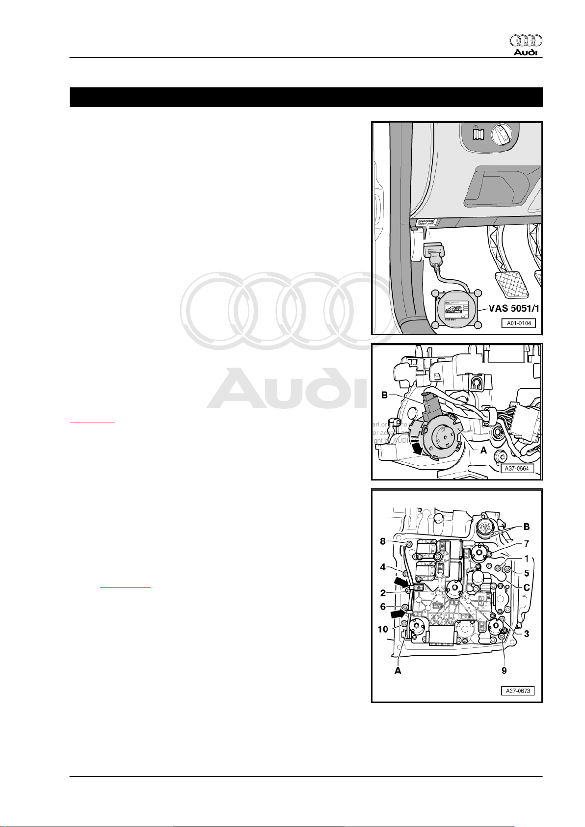
Diagnostic connector
Fitting location: below knee padding on left side of steering wheel.
Audi TT 1999 ➤
Selector lever lock solenoid -N110-
Fitting location: the selector lever lock solenoid -N110- -item A- is
located in the selector mechanism.
♦ Checked via self-diagnosis
Removing and installing selector lever lock solenoid -N110-
⇒ page 40
Mechatronic unit for direct shift gearbox -J743-
Fitting location: the mechatronic unit for direct shift gearbox J743- is bolted to the front of the gearbox housing and covered
by the gearbox oil pan.
The control unit is an integrated component of the mechatronic
unit for direct shift gearbox -J743- .
Removing and installing mechatronic unit for direct shift gearbox
-J743- ⇒ page 102 .
1. 25
Page 30
Protected by copyright. Copying for private or commercial purposes, in part or in whole, is not
permitted unless authorised by AUDI AG. AUDI AG does not guarantee or accept any liability
with respect to the correctness of information in this document. Copyright by AUDI AG.
Audi TT 1999 ➤
Direct shift gearbox 02E, four-wheel drive - Edition 12.2006
Gearbox input speed sender -G182- / oil temperature sender for
multi-plate clutch -G509-
Fitting location: the gearbox input speed sender -G182- / oil tem‐
perature sender for multi-plate clutch -G509- -item A- is bolted to
the gearbox housing below the mechatronic unit for direct shift
gearbox -J743- .
♦ Checked via self-diagnosis
Removing and installing gearbox input speed sender -G182- / oil
temperature sender for multi-plate clutch -G509- ⇒ page 106 .
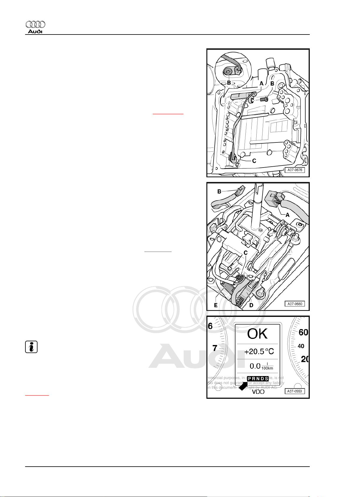
Selector lever -E313- with tiptronic switch -F189-
Fitting location: the selector lever -E313- with tiptronic switch F189- is integrated in the selector mechanism. These compo‐
nents cannot be renewed separately. Several versions available.
For correct allocation refer to ⇒ Parts catalogue .
♦ Checked via self-diagnosis
D - Electrical connector for tiptronic switch -F189-
Remove and install selector lever -E313- with tiptronic switch F189- only together with selector mechanism ⇒ page 38 .
Selector lever position display -Y6-
Fitting location: integrated into instrument cluster
Note
The selector lever position display can only be renewed together
with the instrument cluster.
If the selector lever position display flashes or is illuminated, take
note of the safety functions of the gearbox control unit
⇒ page 7 .
Removing and installing instrument cluster ⇒ Electrical system;
Rep. Gr. 90
26 Rep. Gr.34 - Controls, housing
Page 31

Protected by copyright. Copying for private or commercial purposes, in part or in whole, is not
permitted unless authorised by AUDI AG. AUDI AG does not guarantee or accept any liability
with respect to the correctness of information in this document. Copyright by AUDI AG.
Direct shift gearbox 02E, four-wheel drive - Edition 12.2006
Brake light switch -F-
Fitting location: the brake light switch -arrow- is located on pedal
cluster.
♦ Signal transmission from engine control unit to gearbox control
unit via CAN bus
♦ Checked via self-diagnosis
Removing and installing brake light switch ⇒ Brake system; Rep.
Gr. 46 .
Note
Switch may only be fitted once so as to ensure a firm fit.
Kickdown switch -F8-
An adapted value from accelerator position sender -G79- and ac‐
celerator position sender 2 -G185- (integrated in accelerator ped‐
al module) is stored in the engine control unit as the kickdown
signal.
♦ Checked via self-diagnosis
♦ Signal transmission from engine control unit to gearbox control
unit via CAN bus
Removing and installing accelerator pedal module: ⇒ Fuel supply
system, petrol engines; Rep. Gr. 20 .
Audi TT 1999 ➤
1. 27
Page 32

Protected by copyright. Copying for private or commercial purposes, in part or in whole, is not
permitted unless authorised by AUDI AG. AUDI AG does not guarantee or accept any liability
with respect to the correctness of information in this document. Copyright by AUDI AG.
Audi TT 1999 ➤
Direct shift gearbox 02E, four-wheel drive - Edition 12.2006
2 Servicing selector mechanism
WARNING
Before working on vehicle while engine is running, shift selec‐
tor lever into position “P” and apply handbrake.
Overview:
♦ Checking selector mechanism ⇒ page 28
♦ Checking and adjusting selector lever cable ⇒ page 29
♦ Checking function of ignition key removal lock ⇒ page 33
♦ Dismantling and assembling selector mechanism
⇒ page 35
♦ Removing and installing selector lever handle ⇒ page 37
♦ Removing and installing selector mechanism cover
⇒ page 37
♦ Removing and installing selector mechanism ⇒ page 38
♦ Removing and installing tiptronic switch -F189- ⇒ page 40
♦ Removing and installing selector lever lock solenoid -N110-
⇒ page 40
♦ Removing and installing selector lever cable ⇒ page 41
♦ Removing and installing locking cable ⇒ page 48
♦ Adjusting locking cable ⇒ page 50
♦ Overview of connectors on selector mechanism ⇒ page 51
2.1 Checking selector mechanism
♦ It should not be possible to operate the starter while the se‐
lector lever is in position “S”, “D” or “R” or in the tiptronic
position.
♦ When travelling at speeds above 5 km/h and shifting into se‐
lector lever position “N”, the solenoid for the selector lever lock
must not engage and block the selector lever. The selector
lever can be shifted into a driving gear.
♦ When travelling at speeds below 5 km/h (almost stationary)
and shifting into selector lever position “N”, the solenoid for the
selector lever lock should only engage after about 1 second.
Selector lever cannot be shifted out of “N” position until brake
pedal is depressed.
Selector lever in position “P”, button on selector lever pressed in
and ignition switched on:
• Brake pedal not depressed:
When button is pressed in, selector lever is locked and cannot be
shifted out of “P” position. Solenoid for selector lever lock blocks
selector lever.
• Brake pedal depressed:
Solenoid for selector lever lock releases selector lever. It is pos‐
sible to shift into a driving gear. Shift selector lever slowly from
“P” position through “R, N, D and S” and check whether the dis‐
play in the dash panel insert shows the correct selector lever
position in each case.
28 Rep. Gr.34 - Controls, housing
Page 33

Protected by copyright. Copying for private or commercial purposes, in part or in whole, is not
permitted unless authorised by AUDI AG. AUDI AG does not guarantee or accept any liability
with respect to the correctness of information in this document. Copyright by AUDI AG.
Direct shift gearbox 02E, four-wheel drive - Edition 12.2006
Selector lever in position “N”, button on selector lever pressed in
and ignition switched on:
• Brake pedal not depressed:
Selector lever is locked and cannot be shifted out of “N”position.
Solenoid for selector lever lock blocks selector lever.
• Brake pedal depressed:
Solenoid for selector lever lock releases selector lever. It is pos‐
sible to shift into a driving gear.
Note
When brake pedal is depressed, it is also possible to shift from
“N” to “D” position without pressing the button on the selector lev‐
er. However, to shift from “N” to “R” you do have to additionally
press the button on the selector lever.
Selector lever in position “D”, ignition switched on:
The selector lever is locked and cannot be shifted from “D” to “S”
position.
• Press button on selector lever:
The selector lever is released and can be shifted from “D” to “S”
position.
Selector lever in position “D”, ignition and lights switched on:
• Shift selector lever into tiptronic gate:
The illuminated “D” symbol in the selector lever position indicator
should go out and the “+” and “-” symbols should light up.
The selector lever position indicator in the instrument cluster
should switch from “PRNDS” to “654321” when the selector lever
is moved into the tiptronic gate.
• Move the selector lever in the tiptronic gate to “+” and “–”.
When you move the selector lever to “+” or “–”, the display
“654321” in the instrument cluster should move one gear up or
down accordingly.
– Check selector lever cable and adjust if necessary
⇒ page 29 .
– Check ignition key removal lock ⇒ page 33 .
Audi TT 1999 ➤
2.2 Checking selector lever cable
– Shift selector lever into position “P”.
– Switch off ignition.
– Loosen clamp -4- and detach intake hose and connector -1-
from air mass meter.
– If fitted, disconnect hose -5- from air cleaner housing.
– Unscrew bolts -2- and -3- to remove complete air cleaner
housing.
2. Servicing selector mechanism 29
Page 34

Protected by copyright. Copying for private or commercial purposes, in part or in whole, is not
permitted unless authorised by AUDI AG. AUDI AG does not guarantee or accept any liability
with respect to the correctness of information in this document. Copyright by AUDI AG.
Audi TT 1999 ➤
Direct shift gearbox 02E, four-wheel drive - Edition 12.2006
– Push securing clip -A- upwards and detach it in
-direction of arrow-.
Note
Illustration shows version on vehicles with vehicle ID No. to
8N 41013847.
– Press selector lever cable off selector shaft lever in direction
of arrow and place on top.
– Do not loosen bolt -B-.
– Put the selector lever cable aside in such a way that the end
can move freely.
Note
Do not bend or kink the selector lever cable.
– Move selector lever from “P” to “S”.
– Check protective sleeve on selector mechanism (on front of
selector lever cable) for damage, if necessary renew cable.
– Shift selector lever into position “P”.
• Selector mechanism and selector lever cable should move
smoothly, if necessary renew selector lever cable
( ⇒ page 41 ) or service selector mechanism.
– Carefully press selector lever cable onto selector shaft lever
in opposite direction of -arrow-.
– Fit securing clip -A- and press downwards to secure.
2.3 Adjusting selector lever cable - vehicles
with vehicle ID No. to 8N 41013847
– Shift selector lever into position “P”.
– Switch off ignition.
– Loosen clamp -4- and detach intake hose and connector -1-
from air mass meter.
– If fitted, disconnect hose -5- from air cleaner housing.
– Unscrew bolts -2- and -3- to remove complete air cleaner
housing.
30 Rep. Gr.34 - Controls, housing
Page 35

Protected by copyright. Copying for private or commercial purposes, in part or in whole, is not
permitted unless authorised by AUDI AG. AUDI AG does not guarantee or accept any liability
with respect to the correctness of information in this document. Copyright by AUDI AG.
Direct shift gearbox 02E, four-wheel drive - Edition 12.2006
– Loosen bolt -B-.
– Bring selector shaft lever into position “P” on gearbox.
– Turn both front wheels in one direction, e.g. by pushing the
vehicle forwards, until the detent lever in the gearbox engages
in the parking lock gear and the wheels are blocked (it is not
possible to turn them both in the same direction simultane‐
ously).
Note
The selector lever must remain in “P” position when clamping bolt
-B- is loosened, otherwise adjustment will not be correct.
– Carefully move selector lever slightly forwards and backwards,
without shifting lever into a different selector lever position.
– Tighten bolt -B- smoothly and evenly (tightening torque: 13
Nm).
Note
Audi TT 1999 ➤
When tightening bolt -B-, make sure the selector lever cable does
not move out of position.
2.4 Adjusting selector lever cable - vehicles with vehicle ID No. from 8N 41013848
Special tools and workshop equipment required
♦ Socket and key -T40031-
Procedure
– Shift selector lever into position “P”.
– Switch off ignition.
2. Servicing selector mechanism 31
Page 36

Protected by copyright. Copying for private or commercial purposes, in part or in whole, is not
permitted unless authorised by AUDI AG. AUDI AG does not guarantee or accept any liability
with respect to the correctness of information in this document. Copyright by AUDI AG.
Audi TT 1999 ➤
Direct shift gearbox 02E, four-wheel drive - Edition 12.2006
– Loosen clamp -4- and detach intake hose and connector -1-
from air mass meter.
– If fitted, disconnect hose -5- from air cleaner housing.
– Unscrew bolts -2- and -3- to remove complete air cleaner
housing.
– Bring selector shaft lever into position “P” on gearbox.
– Turn both front wheels in one direction, e.g. by pushing the
vehicle forwards, until the detent lever in the gearbox engages
in the parking lock gear and the wheels are blocked (it is not
possible to turn them both in the same direction simultane‐
ously).
– Carefully move selector lever slightly forwards and backwards,
without shifting lever into a different selector lever position.
– Remove selector mechanism cover ⇒ page 37 .
– Insert socket and key -T40031- through access hole in selec‐
tor mechanism to loosen the clamping bolt at the rear of
selector lever cable approx. 1 turn.
Note
♦
Loosen clamping bolt approx. 1 turn - do not remove.
♦
Clamping bolt can only be accessed with selector lever in po‐
sition “P”.
♦
With clamping bolt loosened, selector lever must remain in
position “P”.
– Check exact position of selector lever in position “P”.
Note
Do not pull selector lever back or forward while adjusting as this
would give an incorrect adjustment.
– Tighten clamping bolt to 13 Nm carefully and smoothly in this
position, using socket and key -T40031- .
– Install selector mechanism cover ⇒ page 37 .
Perform remaining installation steps in reverse sequence of re‐
moval.
2.5 Checking adjustment of selector lever cable
– Keep button pressed, while pulling selector lever approx. 5
mm to the rear out of position “P”. Then keep lever in this po‐
sition, do not move it into “R”.
– Release selector lever.
• The selector lever should spring back into “N” position auto‐
matically.
– If necessary, adjust selector lever cable
⇒ “2.3 Adjusting selector lever cable - vehicles with vehicle ID
No. to 8N 41013847”, page 30 and
⇒ “2.4 Adjusting selector lever cable - vehicles with vehicle ID
No. from 8N 41013848”, page 31 .
32 Rep. Gr.34 - Controls, housing
Page 37

Protected by copyright. Copying for private or commercial purposes, in part or in whole, is not
permitted unless authorised by AUDI AG. AUDI AG does not guarantee or accept any liability
with respect to the correctness of information in this document. Copyright by AUDI AG.
Direct shift gearbox 02E, four-wheel drive - Edition 12.2006
– Shift selector lever into position “N”.
– Keep button pressed, while pulling selector lever approx. 5
mm to the rear out of position “N”. Then keep lever in this po‐
sition, do not move it into “D”.
– Release selector lever.
• The selector lever should spring back into “N” position auto‐
matically.
– If necessary, adjust selector lever cable
⇒ “2.3 Adjusting selector lever cable - vehicles with vehicle ID
No. to 8N 41013847”, page 30 and
⇒ “2.4 Adjusting selector lever cable - vehicles with vehicle ID
No. from 8N 41013848”, page 31 .
– Keep button pressed, while pushing selector lever approx. 5
mm to the front out of position “N”. Then keep lever in this
position, do not move it into “R”.
– Release selector lever.
• The selector lever should spring back into “N” position auto‐
matically.
– If necessary, adjust selector lever cable
⇒ “2.3 Adjusting selector lever cable - vehicles with vehicle ID
No. to 8N 41013847”, page 30 and
⇒ “2.4 Adjusting selector lever cable - vehicles with vehicle ID
No. from 8N 41013848”, page 31 .
– Check selector mechanism ⇒ page 28 .
Audi TT 1999 ➤
2.6 Checking function of ignition key removal lock
– Move selector lever to “P”
Start
↓
↓ ← ← ← ← ← ← ← ← ← ← ↑
↓
Defective selector mecha‐
↑
nism or defective steering
– Switch off ignition.
lock
– Renew defective compo‐
– Remove ignition key
Can selector lever be
↓
↓
↓
shifted out of “P” when
the button is pressed?
→
Yes
nents
→
Incorrectly adjusted
locking cable?
↑
No
↑
→
Y
e
→
– Correct adjust‐
ment
s
⇒ page 50
Function OK
– Press brake pedal
↓
No
↓
↓
↓
↑
↑
↑
↑
↑
↑
↑
↑
– Insert ignition key
↑
↑
– Switch on ignition
↓
↑
2. Servicing selector mechanism 33
Page 38

Protected by copyright. Copying for private or commercial purposes, in part or in whole, is not
permitted unless authorised by AUDI AG. AUDI AG does not guarantee or accept any liability
with respect to the correctness of information in this document. Copyright by AUDI AG.
Audi TT 1999 ➤
Direct shift gearbox 02E, four-wheel drive - Edition 12.2006
Can selector lever be
→ No → → → → → ↑
shifted out of “P” when
the button is pressed?
– It should be possible to shift se‐
↓
↓
Yes
↓
lector lever to “R, N, D or S”
Can ignition key be removed?
↓
→ →
→ → ↑ ← ← ← ←
Y
↑
↑
↑
↑
↑
↑
↑
↑
↑
e
s
↓
→ → →
No
– Press brake pedal
→
Ignition key can be removed
and selector lever is locked in
– Move selector lever to “P”
“P”.
Ignition key removal lock OK
No
↑
↓
Yes
↓
34 Rep. Gr.34 - Controls, housing
Page 39

Protected by copyright. Copying for private or commercial purposes, in part or in whole, is not
permitted unless authorised by AUDI AG. AUDI AG does not guarantee or accept any liability
with respect to the correctness of information in this document. Copyright by AUDI AG.
Audi TT 1999 ➤
Direct shift gearbox 02E, four-wheel drive - Edition 12.2006
2.7 Dismantling and assembling selector mechanism
Note
Lubricate all bearings and moving surfaces with polycarbamide grease -G 052 142 A2- .
1 - Selector lever handle
❑ Removing and installing
⇒ page 37
2 - Sleeve
❑ Clips into selector lever
handle
❑ Prevents the selector
lever handle from being
pulled off
3 - Bolt, 2 Nm
❑ 8x
4 - Retaining ring
5 - Upper cover
❑ Includes symbol insert
❑ Fit onto guides -arrows-
on frame
⇒ Item 8 (page 35) .
6 - Side cover
❑ Fit onto guides -arrows-
on frame
⇒ Item 8 (page 35) .
❑ Removing and installing
⇒ page 37
7 - Printed circuit
❑ Can be checked in “Gui‐
ded fault finding” using
⇒ Vehicle diagnosis,
testing and information
system VAS 5051
❑ Installation position of
printed circuit
⇒ page 36
❑ To remove and install
printed circuit, first dismantle selector mechanism cover
8 - Frame
9 - Selector lever cable
❑ Do not bend or kink
❑ Checking ⇒ page 29
❑ If the protective sleeve is damaged, the selector lever cable must be renewed
❑ Adjusting ⇒ “2.3 Adjusting selector lever cable - vehicles with vehicle ID No. to 8N 41013847”, page 30
and ⇒ “2.4 Adjusting selector lever cable - vehicles with vehicle ID No. from 8N 41013848”, page 31
❑ Removing and installing ⇒ page 41
❑ Do not lubricate cable eye and ball socket
10 - Nut, 10 Nm
❑ For securing cover to selector mechanism
❑ 4x
2. Servicing selector mechanism 35
Page 40

Protected by copyright. Copying for private or commercial purposes, in part or in whole, is not
permitted unless authorised by AUDI AG. AUDI AG does not guarantee or accept any liability
with respect to the correctness of information in this document. Copyright by AUDI AG.
Audi TT 1999 ➤
Direct shift gearbox 02E, four-wheel drive - Edition 12.2006
❑ Self-locking
❑ Renew
11 - Cover
❑ For selector mechanism
❑ With glued-on gasket
12 - Washer
13 - Intermediate plate for selector mechanism
14 - Bolt
❑ Inserted into intermediate plate
15 - Selector lever lock solenoid -N110-
❑ Removing and installing ⇒ page 40
❑ Can be checked in “Guided fault finding” using ⇒ Vehicle diagnosis, testing and information system VAS
5051
16 - Retainer for locking cable
17 - Selector mechanism
❑ Removing and installing ⇒ page 38
❑ With integrated tiptronic switch -F189-
18 - Bolt, 6 Nm
❑ 3x
19 - Locking cable
❑ For ignition key removal lock
❑ Must not be kinked
❑ Removing and installing ⇒ page 48
❑ Adjusting ⇒ page 50
❑ Checking operation of the ignition key withdrawal lock ⇒ page 33 .
20 - Steering lock
21 - Clip
❑ Installation position: Fit clip from above. Angled ends of clip must point towards steering lock.
Installation position of printed circuit
– Fit bores in printed circuit onto guides on frame -arrows-.
• When installing cover, make sure wiring harness -A- is not
trapped and that printed circuit is not deformed.
36 Rep. Gr.34 - Controls, housing
Page 41

Protected by copyright. Copying for private or commercial purposes, in part or in whole, is not
permitted unless authorised by AUDI AG. AUDI AG does not guarantee or accept any liability
with respect to the correctness of information in this document. Copyright by AUDI AG.
Direct shift gearbox 02E, four-wheel drive - Edition 12.2006
2.8 Removing and installing selector lever handle
Removing
– Shift selector lever to position “D”.
– Slide sleeve -1- downwards.
– Pull locking button -2- out of handle -3- as far as it will go
-arrow-.
– Use a wire clip or similar -4- to secure the locking button so
that it does not spring back.
– Now pull the handle off the selector lever.
Installing
– Shift selector lever to position “D”.
– Pull locking button -2- out of handle -3- as far as it will go
-arrow-.
– Use a wire clip or similar -4- to secure the locking button so
that it does not spring back.
– Now press the handle onto selector lever as far as it will go.
Audi TT 1999 ➤
Note
Installation position: Button points to driver.
– Remove wire clip.
– Press the button so that the pull lever -5- engages in the pull
rod -6-.
The button should now spring back onto the stop.
– Push sleeve -1- upwards. You should feel the sleeve engage
in the handle.
– Shift selector lever to position “P”.
2.9 Removing and installing selector mech‐
anism cover
Removing
– Shift selector lever to position “D”.
– Switch off ignition.
– Remove selector lever handle ⇒ page 37 .
– Remove centre console (rear) ⇒ General body repairs, inte‐
rior; Rep. Gr. 68 .
2. Servicing selector mechanism 37
Page 42

Protected by copyright. Copying for private or commercial purposes, in part or in whole, is not
permitted unless authorised by AUDI AG. AUDI AG does not guarantee or accept any liability
with respect to the correctness of information in this document. Copyright by AUDI AG.
Audi TT 1999 ➤
Direct shift gearbox 02E, four-wheel drive - Edition 12.2006
– Carefully release the frame by bending the four hooks out‐
wards -arrows- with a screwdriver. Then remove together with
retaining ring, printed circuit and cover -A-.
– Detach connector -B- from selector mechanism cover and lift
off cover.
Installing
Perform installation in reverse sequence of removal. Note the fol‐
lowing:
– Install centre console (rear) ⇒ General body repairs, interior;
Rep. Gr. 68 .
– Install selector lever handle ⇒ page 37 .
2.10 Removing and installing selector mech‐
anism
Removing
– Shift selector lever to position “D”.
– Switch off ignition.
– Remove selector lever handle ⇒ page 37 .
– Remove centre console (rear) ⇒ General body repairs, inte‐
rior; Rep. Gr. 68 .
– Shift selector lever into position “P”.
– Remove selector mechanism cover ⇒ page 37 .
– Lift up locking lever -A- and pull off locking cable in direction
of arrow.
Note
Do not loosen bolt -B-!
38 Rep. Gr.34 - Controls, housing
Page 43

Protected by copyright. Copying for private or commercial purposes, in part or in whole, is not
permitted unless authorised by AUDI AG. AUDI AG does not guarantee or accept any liability
with respect to the correctness of information in this document. Copyright by AUDI AG.
Direct shift gearbox 02E, four-wheel drive - Edition 12.2006
– Unplug connector -A- from selector mechanism.
– Unscrew 2 nuts -1- securing selector mechanism (rear) to
body.
– Unscrew bolts -2-.
– Lift out the selector mechanism.
Note
Do not bend or kink the selector lever cable.
– Use screwdriver or similar to pry selector lever cable -B- off
lever -A- on underside of selector mechanism.
Audi TT 1999 ➤
Note
Illustration shows version on vehicles with vehicle ID No. to
8N 41013847.
– Lift off selector mechanism.
Installing
Perform installation in reverse sequence of removal. Note the fol‐
lowing:
Refer to
⇒ “2.7 Dismantling and assembling selector mechanism”,
page 35 for tightening torques for bolts and nuts as well as infor‐
mation on whether bolts and nuts have to be renewed.
Note
Do not bend or kink the selector lever cable.
– Press selector lever cable -B- onto lever -A- on underside of
selector mechanism.
• Retaining lugs on inside of selector lever cable must engage
in groove on lever -arrow-.
2. Servicing selector mechanism 39
Page 44

Protected by copyright. Copying for private or commercial purposes, in part or in whole, is not
permitted unless authorised by AUDI AG. AUDI AG does not guarantee or accept any liability
with respect to the correctness of information in this document. Copyright by AUDI AG.
Audi TT 1999 ➤
Direct shift gearbox 02E, four-wheel drive - Edition 12.2006
– Install bolts -2-.
– Install 2 nuts -1- securing selector mechanism (rear) to body.
– Plug in connector -A-.
– Adjust locking cable ⇒ page 50 .
– Checking operation of the ignition key withdrawal lock
⇒ page 33 .
– Install selector mechanism cover ⇒ page 37 .
– Install centre console (rear) ⇒ General body repairs, interior;
Rep. Gr. 68 .
– Install selector lever handle ⇒ page 37 .
– Adjust selector lever cable ⇒ page 29 .
– Check selector mechanism ⇒ page 28 .
2.11 Removing and installing tiptronic switch
-F189-
The tiptronic switch is integrated in the selector mechanism; it is
therefore not possible to renew only the switch on its own. To
renew it you must renew the selector mechanism ⇒ page 38 .
2.12 Removing and installing selector lever lock solenoid -N110-
Removing
– Remove selector mechanism ⇒ page 38
– Unplug connector -B- from selector lever lock solenoid -
N110- .
– Press retaining tab -A- to rear and simultaneously turn sole‐
noid in direction of arrow.
– Pull out selector lever lock solenoid.
Installing
Perform installation in reverse sequence of removal. Note the fol‐
lowing:
Refer to
⇒ “2.7 Dismantling and assembling selector mechanism”,
page 35 for tightening torques for bolts and nuts as well as infor‐
mation on whether bolts and nuts have to be renewed.
– Check selector mechanism ⇒ page 28 .
40 Rep. Gr.34 - Controls, housing
Page 45

Protected by copyright. Copying for private or commercial purposes, in part or in whole, is not
permitted unless authorised by AUDI AG. AUDI AG does not guarantee or accept any liability
with respect to the correctness of information in this document. Copyright by AUDI AG.
Direct shift gearbox 02E, four-wheel drive - Edition 12.2006
2.13 Removing and installing selector lever cable
Removing
– Loosen clamp -4- and detach intake hose and connector -1-
from air mass meter.
– If fitted, disconnect hose -5- from air cleaner housing.
– Unscrew bolts -2- and -3- to remove complete air cleaner
housing.
– Shift selector lever into position “P”.
– Remove locking plate -C-.
Note
Illustration shows version on vehicles with vehicle ID No. to
8N 41013847.
Audi TT 1999 ➤
– Push securing clip -A- upwards and detach it in direction of
arrow.
– Press selector lever cable off selector shaft lever in direction
of arrow and place on top.
– Do not loosen bolt -B-.
Note
Do not bend or kink the selector lever cable.
– Unhook selector lever cable -1- from clip -arrow- on gearbox.
2. Servicing selector mechanism 41
Page 46

Protected by copyright. Copying for private or commercial purposes, in part or in whole, is not
permitted unless authorised by AUDI AG. AUDI AG does not guarantee or accept any liability
with respect to the correctness of information in this document. Copyright by AUDI AG.
Audi TT 1999 ➤
Direct shift gearbox 02E, four-wheel drive - Edition 12.2006
– Remove centre noise insulation -fasteners 1 ... 3-.
– Unbolt protective cover -arrows-.
– Detach electrical connectors for all Lambda probes and move
clear.
– Unscrew wire guide -arrows-.
– Unbolt catalytic converter from front exhaust pipe -arrows-.
Note
To prevent damage, the flexible joints in the front exhaust pipe
must not be bent further than 10°.
42 Rep. Gr.34 - Controls, housing
Page 47

Protected by copyright. Copying for private or commercial purposes, in part or in whole, is not
permitted unless authorised by AUDI AG. AUDI AG does not guarantee or accept any liability
with respect to the correctness of information in this document. Copyright by AUDI AG.
Direct shift gearbox 02E, four-wheel drive - Edition 12.2006
– Disconnect exhaust system at clamp -arrows-.
– Push clamp towards rear and remove catalytic converter.
– Unscrew centre heat shield and bracket for exhaust system
-arrows-.
– Mark position of propshaft with flexible coupling in relation to
bevel box flange.
Audi TT 1999 ➤
– Unscrew propshaft with flexible coupling from bevel box flange
-arrows-.
Note
When slackening off bolts, counterhold propshaft flange/final
drive with a suitable lever.
– Unscrew propshaft from flexible coupling at bevel box
-arrows-.
Note
When slackening off bolts, counterhold triangular flange with a
suitable lever.
– Press front propshaft tube as far as possible towards the rear.
2. Servicing selector mechanism 43
Page 48

Protected by copyright. Copying for private or commercial purposes, in part or in whole, is not
permitted unless authorised by AUDI AG. AUDI AG does not guarantee or accept any liability
with respect to the correctness of information in this document. Copyright by AUDI AG.
Audi TT 1999 ➤
Direct shift gearbox 02E, four-wheel drive - Edition 12.2006
Note
After loosening bolts -A- (see following illustration N34-0712) the
engine/gearbox assembly will swing slightly to the rear. Make
sure that the seal -arrow- in the flange of the propshaft is not
damaged when removing and installing.
– First unscrew bolts -A- and then bolts -B- on pendulum sup‐
port.
– Remove pendulum support.
– Disconnect front propshaft tube from rear propshaft tube
-arrows-.
– Push front propshaft tube towards the front and swivel out from
flange of rear propshaft tube.
Note
Take care when swivelling out that the front propshaft tube is
pushed downwards as little as possible.
– Carefully push the engine incl. gearbox to the front and prop
it up in this position. You may require the help of a second
mechanic.
Note
This step has to be performed so that the propshaft tube can be
pulled off the centring pin.
– Carefully pull front propshaft tube from centring pin.
Note
♦
The seal -arrow- in the flange of the propshaft must not be
damaged. If seal is damaged propshaft must be renewed.
♦
Pull off propshaft horizontally from guide pin.
– Swivel front propshaft tube downwards and remove.
44 Rep. Gr.34 - Controls, housing
Page 49

Protected by copyright. Copying for private or commercial purposes, in part or in whole, is not
permitted unless authorised by AUDI AG. AUDI AG does not guarantee or accept any liability
with respect to the correctness of information in this document. Copyright by AUDI AG.
Direct shift gearbox 02E, four-wheel drive - Edition 12.2006
– Remove heat shield (front) -arrows-.
– Unscrew the four nuts -arrows A-.
Note
The two bolts -arrows B- have not been installed.
– Carefully push cover including protective sleeve forwards over
selector lever cable. Take care not to damage the protective
sleeve.
Audi TT 1999 ➤
– Use screwdriver or similar to pry selector lever cable -B- off
lever -A-.
Note
Illustration shows version on vehicles with vehicle ID No. to
8N 41013847.
– Press the two retaining lugs together -arrows- in order to re‐
lease selector lever cable from bracket on underside of selec‐
tor mechanism.
– Carefully pull selector lever cable out of selector mechanism.
Installing
Perform installation in reverse sequence of removal. Note the fol‐
lowing:
Refer to
⇒ “2.7 Dismantling and assembling selector mechanism”,
page 35 for tightening torques for bolts and nuts as well as infor‐
mation on whether bolts and nuts have to be renewed.
Note
♦
Check the protective sleeve for damage; the protective sleeve
can only be renewed together with the selector lever cable.
♦
Check that the protective sleeve is not twisted and is fitted
correctly.
2. Servicing selector mechanism 45
Page 50

Protected by copyright. Copying for private or commercial purposes, in part or in whole, is not
permitted unless authorised by AUDI AG. AUDI AG does not guarantee or accept any liability
with respect to the correctness of information in this document. Copyright by AUDI AG.
Audi TT 1999 ➤
Direct shift gearbox 02E, four-wheel drive - Edition 12.2006
– Press selector lever cable -B- onto lever -A- on underside of
selector mechanism.
• Retaining lugs on inside of selector lever cable must engage
in groove on lever -arrow-.
Note
Illustration shows version on vehicles with vehicle ID No. to
8N 41013847.
– Engage selector lever cable in bracket on underside of selec‐
tor mechanism.
– Carefully press selector lever cable onto selector shaft lever
on gearbox in opposite direction of -arrow-.
– Fit securing clip -A- and press downwards to secure.
– Install locking plate -C-.
– Move selector lever from “P” to “S”.
• Selector mechanism and selector lever cable must move free‐
ly. If necessary renew selector lever cable or service selector
mechanism.
– Shift selector lever into position “P”.
– Secure cover with attached gasket to shift unit (hand-tight).
When doing this check that gasket makes full contact.
– Tighten the nuts -arrows A-.
Note
The two bolts -arrows B- have not been installed.
– Insert protective sleeve on selector lever cable in cover.
– Secure pendulum support to gearbox with new bolts
-arrows B-.
– Press engine/gearbox assembly towards bulkhead; the stub
shaft on the bevel box must be guided carefully into the prop‐
shaft flange when doing this.
46 Rep. Gr.34 - Controls, housing
Page 51

Protected by copyright. Copying for private or commercial purposes, in part or in whole, is not
permitted unless authorised by AUDI AG. AUDI AG does not guarantee or accept any liability
with respect to the correctness of information in this document. Copyright by AUDI AG.
Direct shift gearbox 02E, four-wheel drive - Edition 12.2006
Note
♦
When removing and installing, do not damage seals in prop‐
shaft flanges. If seals are damaged, the propshaft must be
renewed.
♦
Push propshaft horizontally onto guide pin ⇒ Rear final drive
02D and 0AV; Rep. Gr. 39 .
– Secure pendulum support to subframe with new bolts
-arrows A-.
Audi TT 1999 ➤
– Bolt flexible coupling on propshaft onto bevel box flange
-arrows- ⇒ Rear final drive 02D and 0AV; Rep. Gr. 39 .
Note
Take note of the markings that were made on the propshaft and
flange when removing. These must align with each other again
-arrows-.
– Install exhaust system so it is free of stress ⇒ Rep. Gr. 26 .
– Adjust selector lever cable ⇒ page 29 .
– Check selector mechanism ⇒ page 28 .
2. Servicing selector mechanism 47
Page 52

Protected by copyright. Copying for private or commercial purposes, in part or in whole, is not
permitted unless authorised by AUDI AG. AUDI AG does not guarantee or accept any liability
with respect to the correctness of information in this document. Copyright by AUDI AG.
Audi TT 1999 ➤
Direct shift gearbox 02E, four-wheel drive - Edition 12.2006
2.14 Removing and installing locking cable
Removing
Caution
Follow steps required when disconnecting battery ⇒ Electrical
system; Rep. Gr. 27 .
– With ignition switched off, disconnect earth wire -arrow- at
battery in luggage compartment under floor cover.
– Remove airbag module (driver's side) and steering wheel ⇒
General body repairs, interior; Rep. Gr. 69 .
– Remove trim (left-side) below dash panel ⇒ General body re‐
pairs, interior; Rep. Gr. 68 .
– Remove steering column trim ⇒ General body repairs, interior;
Rep. Gr. 70 .
– Unscrew handle for adjusting steering column height and po‐
sition.
– Turn ignition key to "ignition on" position.
– Shift selector lever into position “P”.
– Pull out clip -2- for locking cable -3-.
– Pull locking cable out of steering lock -1-.
– Remove selector lever handle ⇒ page 37 .
– Remove centre console (rear) ⇒ General body repairs, inte‐
rior; Rep. Gr. 68 .
48 Rep. Gr.34 - Controls, housing
Page 53

Protected by copyright. Copying for private or commercial purposes, in part or in whole, is not
permitted unless authorised by AUDI AG. AUDI AG does not guarantee or accept any liability
with respect to the correctness of information in this document. Copyright by AUDI AG.
Direct shift gearbox 02E, four-wheel drive - Edition 12.2006
– Lift up locking lever -A- and pull off locking cable in direction
of -arrow-.
Note
Do not loosen bolt -B-!
– Pull locking cable out of dash panel.
Installing
Perform installation in reverse sequence of removal. Note the fol‐
lowing:
• The locking cable must not be kinked.
• Adjust locking cable after installing ⇒ page 50 .
– Locking cable -arrow- must be routed from steering lock to
selector mechanism in such a way that it passes behind wiring
harness -1- and underneath footwell air outlet -2- and the car‐
pet -3-.
– Shift selector lever into position “P”.
Audi TT 1999 ➤
– Lift locking lever -A- and fit locking cable in opposite direction
to -arrow-, if necessary loosen bolt -B-.
2. Servicing selector mechanism 49
Page 54

Protected by copyright. Copying for private or commercial purposes, in part or in whole, is not
permitted unless authorised by AUDI AG. AUDI AG does not guarantee or accept any liability
with respect to the correctness of information in this document. Copyright by AUDI AG.
Audi TT 1999 ➤
Direct shift gearbox 02E, four-wheel drive - Edition 12.2006
– Push locking cable into steering lock.
• The flat side of the locking cable points downwards.
– Fit clip -2- of locking cable -3-.
• Installation position: Fit clip from above. Angled ends of clip
must point towards steering lock.
– Ensure that the clip is properly engaged.
– Adjust locking cable ⇒ page 50 .
– Checking operation of the ignition key withdrawal lock
⇒ page 33 .
– Install centre console (rear) ⇒ General body repairs, interior;
Rep. Gr. 68 .
– Install selector lever handle ⇒ page 37 .
– Install trim (left-side) below dash panel ⇒ General body re‐
pairs, interior; Rep. Gr. 68 .
– Install steering column trim ⇒ General body repairs, interior;
Rep. Gr. 70 .
– Install handle for adjusting steering column height and posi‐
tion.
– Install steering wheel and airbag ⇒ General body repairs, in‐
terior; Rep. Gr. 69 .
– Follow steps required after connecting battery ⇒ Electrical
system; Rep. Gr. 27 .
2.15 Adjusting locking cable
Special tools and workshop equipment required
♦ Locking cable adjustment gauge -3352 A-
Requirements
• Locking cable must be in installation position.
• Rear centre console has been removed.
• Selector lever is in position “P”
• Ignition key is in removal position.
• Steering column is in lowest/rearmost position.
50 Rep. Gr.34 - Controls, housing
Page 55

Protected by copyright. Copying for private or commercial purposes, in part or in whole, is not
permitted unless authorised by AUDI AG. AUDI AG does not guarantee or accept any liability
with respect to the correctness of information in this document. Copyright by AUDI AG.
Direct shift gearbox 02E, four-wheel drive - Edition 12.2006
Procedure
Caution
To adjust the locking cable always proceed as described be‐
low.
– Remove selector lever handle ⇒ page 37 .
– Remove centre console (rear) ⇒ General body repairs, inte‐
rior; Rep. Gr. 68 .
– Remove selector mechanism cover ⇒ page 37 .
– Loosen bolt at support bracket.
– Fit locking cable adjustment gauge -3352 A- between locking
lever -1- and locking cable eye -2-.
– To compensate for play, pull support bracket up to limit stop
in direction of arrow.
• In this position it should be easy to remove and insert the lock‐
ing cable adjustment gauge -3352 A- .
– Tighten bolt -B- at support bracket (10 Nm).
– Remove adjustment gauge.
– Checking operation of the ignition key withdrawal lock
⇒ page 33 .
– Install selector mechanism cover ⇒ page 37 .
– Install rear centre console. ⇒ General body repairs, interior;
Rep. Gr. 68
– Install selector lever handle ⇒ page 37 .
Audi TT 1999 ➤
2.16 Checking connectors on selector mech‐
anism
Before servicing or checking the connectors, the cause of the fault
must be determined via the “Guided fault finding” ⇒ Vehicle di‐
agnosis, testing and information system VAS 5051.
Before checking connectors, all control units in vehicle should be
checked for fault entries; if necessary eliminate faults ⇒ Vehicle
diagnosis, testing and information system VAS 5051.
2. Servicing selector mechanism 51
Page 56

Protected by copyright. Copying for private or commercial purposes, in part or in whole, is not
permitted unless authorised by AUDI AG. AUDI AG does not guarantee or accept any liability
with respect to the correctness of information in this document. Copyright by AUDI AG.
Audi TT 1999 ➤
Direct shift gearbox 02E, four-wheel drive - Edition 12.2006
– Check connectors according to ⇒ Current flow diagrams, Elec‐
trical fault finding and Fitting locations.
A - Connector for wiring from the vehicle's wiring harness to se‐
lector lever (with CAN lines)
B - Connector for selector mechanism cover
C - Connector for selector lever lock solenoid -N110-
D - Connector for tiptronic switch -F189-
52 Rep. Gr.34 - Controls, housing
Page 57

Protected by copyright. Copying for private or commercial purposes, in part or in whole, is not
permitted unless authorised by AUDI AG. AUDI AG does not guarantee or accept any liability
with respect to the correctness of information in this document. Copyright by AUDI AG.
Direct shift gearbox 02E, four-wheel drive - Edition 12.2006
3 Removing and installing gearbox
3.1 Removing gearbox
Special tools and workshop
equipment required
♦ Support bracket -10-222 A-
♦ Rack -10-222 A /1-
♦ Engine and gearbox jack -
V.A.G 1383 A-
♦ Gearbox support -3282-
♦ Shackle -10-222 A /12-
♦ Hose clamps, up to Ø 25
mm -3094-
Audi TT 1999 ➤
♦ Hooks -3004-
3. Removing and installing gearbox 53
Page 58

Protected by copyright. Copying for private or commercial purposes, in part or in whole, is not
permitted unless authorised by AUDI AG. AUDI AG does not guarantee or accept any liability
with respect to the correctness of information in this document. Copyright by AUDI AG.
Audi TT 1999 ➤
Direct shift gearbox 02E, four-wheel drive - Edition 12.2006
♦ Pin -3282/29-
♦ Adjustment plate -3282/42 A-
Note
♦
Rules for cleanliness when working on the gearbox
⇒ page 12 .
♦
General repair instructions ⇒ page 9 .
♦
Observe notes on direct shift gearbox 02E ⇒ page 6
Removing
Note
All cable ties which are released or cut open when removing the
gearbox must be refitted in the same position when installing the
gearbox.
– Remove cover panel (front left) -arrows-.
Caution
Follow steps required when disconnecting battery ⇒ Electrical
system; Rep. Gr. 27 .
54 Rep. Gr.34 - Controls, housing
Page 59

Protected by copyright. Copying for private or commercial purposes, in part or in whole, is not
permitted unless authorised by AUDI AG. AUDI AG does not guarantee or accept any liability
with respect to the correctness of information in this document. Copyright by AUDI AG.
Direct shift gearbox 02E, four-wheel drive - Edition 12.2006
– With ignition switched off, disconnect earth wire -arrow- at
battery in luggage compartment under floor cover.
– Loosen clamp -4- and detach intake hose and connector -1-
from air mass meter.
– If fitted, disconnect hose -5- from air cleaner housing.
– Unscrew bolts -2- and -3- to remove complete air cleaner
housing.
Audi TT 1999 ➤
– Unclip complete main fuse box/battery -A- including all wiring
from battery tray.
– Remove battery tray -arrows-.
Note
The sole purpose of the battery tray is to secure the main fuse
box/battery.
3. Removing and installing gearbox 55
Page 60

Protected by copyright. Copying for private or commercial purposes, in part or in whole, is not
permitted unless authorised by AUDI AG. AUDI AG does not guarantee or accept any liability
with respect to the correctness of information in this document. Copyright by AUDI AG.
Audi TT 1999 ➤
Direct shift gearbox 02E, four-wheel drive - Edition 12.2006
– Shift selector lever into position “P”.
– Push securing clip -A- upwards and detach it in direction of
arrow.
– Press selector lever cable off selector shaft lever in direction
of arrow and place on top.
– Do not loosen bolt -B-.
– Unscrew the two bolts -1-.
Note
Do not bend or kink the selector lever cable.
– Touch vehicle earth with your hand (without gloves) to dis‐
charge any static electricity.
– Turn bayonet catch -1- of 20-pin connector to release and de‐
tach it from gearbox.
Caution
Never touch contacts in gearbox connector with your hands,
as static discharge would damage the control unit and mecha‐
tronic unit.
– Remove electrical connections from starter.
– Remove starter ⇒ Electrical system; Rep. Gr. 27 .
– Clamp off gear oil cooler hoses using hose clamps -3094- and
detach at gear oil cooler -A-.
– Seal off gear oil cooler with clean plugs.
– Remove all engine/gearbox connecting bolts which are ac‐
cessible from above.
56 Rep. Gr.34 - Controls, housing
Page 61

Protected by copyright. Copying for private or commercial purposes, in part or in whole, is not
permitted unless authorised by AUDI AG. AUDI AG does not guarantee or accept any liability
with respect to the correctness of information in this document. Copyright by AUDI AG.
Direct shift gearbox 02E, four-wheel drive - Edition 12.2006
– Assemble support bracket -10-222 A- together with rack
-10-222 A/1- and adapters -10-222 A/3- .
– Position support bracket on wheel housing flange.
– If there are hoses or wiring in vicinity of engine lifting eyes for
support bracket -10-222 A- , detach these now.
– Fix a shackle -10-222 A/12- -1- to engine lifting eye (rear right).
– Take up weight of engine/gearbox assembly via the spindles.
– Remove centre noise insulation -fasteners 1 ... 3-.
Audi TT 1999 ➤
– Remove noise insulation (left-side) -arrows-.
– Remove both front wheels.
– If fitted, unscrew bracket for headlight range control in left
wheel housing -arrows- and tie it up to one side.
3. Removing and installing gearbox 57
Page 62

Protected by copyright. Copying for private or commercial purposes, in part or in whole, is not
permitted unless authorised by AUDI AG. AUDI AG does not guarantee or accept any liability
with respect to the correctness of information in this document. Copyright by AUDI AG.
Audi TT 1999 ➤
Direct shift gearbox 02E, four-wheel drive - Edition 12.2006
– If fitted, remove guard plate at bottom of gearbox -arrows-.
– Press out right and left swivel joints ⇒ Running gear, front-
wheel drive and four-wheel drive; Rep. Gr. 40 .
– Unscrew bolts -1- and -2- and remove bracket -A-.
– Unscrew nut -1- and push bracket -A- upwards so it does not
get stuck when the gearbox is lowered.
– Disconnect exhaust system at clamp -arrows-.
– Push clamp towards the rear.
58 Rep. Gr.34 - Controls, housing
Page 63

Protected by copyright. Copying for private or commercial purposes, in part or in whole, is not
permitted unless authorised by AUDI AG. AUDI AG does not guarantee or accept any liability
with respect to the correctness of information in this document. Copyright by AUDI AG.
Direct shift gearbox 02E, four-wheel drive - Edition 12.2006
– Tie up exhaust system with a chain. To do so, engage hooks
-3004- in openings on underbody (if necessary remove plugs).
Note
The flexible joint (de-coupling element) in the exhaust system
must not be bent more than 10° – otherwise it can be damaged.
– Unbolt heat shield for drive shaft (right-side) from bevel box.
– Unbolt drive shafts from gearbox flange shafts.
– Lift drive shaft (right-side) up and secure with wire.
– Move drive shaft (left-side) clear towards the rear and secure
with wire.
– Mark position of propshaft with flexible coupling in relation to
bevel box flange.
Audi TT 1999 ➤
– Unscrew propshaft with flexible coupling from bevel box flange
-arrows-.
– Press propshaft horizontally to rear as far as possible.
Caution
♦ When removing the gearbox, make sure the seal -arrow-
in the propshaft flange is not damaged. If seal is damaged
propshaft must be renewed.
♦ Slackening off bolts for pendulum support/subframe cau‐
ses engine/gearbox assembly to swing forwards slightly.
3. Removing and installing gearbox 59
Page 64

Protected by copyright. Copying for private or commercial purposes, in part or in whole, is not
permitted unless authorised by AUDI AG. AUDI AG does not guarantee or accept any liability
with respect to the correctness of information in this document. Copyright by AUDI AG.
Audi TT 1999 ➤
Direct shift gearbox 02E, four-wheel drive - Edition 12.2006
– First unscrew bolts -A- and then bolts -B- on pendulum sup‐
port.
– Remove pendulum support.
– Push the engine/gearbox assembly forward slightly and then
pull the propshaft off the bevel box.
– Place the propshaft above the bevel box and secure it to pre‐
vent it falling.
– Remove the subframe ⇒ Running gear, front-wheel drive and
four-wheel drive; Rep. Gr. 40 .
– Unscrew bolts -1- and -2- at bracket for bevel box.
– Remove bracket -A- for bevel box.
– Unscrew bolts -1- and -2- and detach gearbox support -A-.
– Lower the engine/gearbox assembly slightly using the spin‐
dles.
60 Rep. Gr.34 - Controls, housing
Page 65

Protected by copyright. Copying for private or commercial purposes, in part or in whole, is not
permitted unless authorised by AUDI AG. AUDI AG does not guarantee or accept any liability
with respect to the correctness of information in this document. Copyright by AUDI AG.
Direct shift gearbox 02E, four-wheel drive - Edition 12.2006
• The distance -a- between gearbox housing and gearbox
mounting should be 100 ... 110 mm.
To remove the direct shift gearbox 02E, set up gearbox support
-3282- with adjustment plate -3282/42 A- and place on engine and
gearbox jack -V.A.G 1383 A- .
– Align arms of gearbox support according to holes in adjust‐
ment plate -3282/42 A- .
– Secure support elements as illustrated on adjustment plate
-3282/42 A- . However, use -retainer plate with drilling- as front
support element.
– Place engine and gearbox jack -V.A.G 1383 A- underneath
vehicle.
• The arrow symbol on the adjustment plate points in the direc‐
tion of travel.
– Align gearbox support -3282- parallel with gearbox.
– Screw pin -3282/29- into gearbox.
– Secure -retainer plate with drilling- firmly to gearbox as illus‐
trated -arrow-.
– Insert last support element in gearbox as illustrated.
– Support the gearbox by raising the engine and gearbox jack -
V.A.G 1383 A- from below.
– Remove remaining engine/gearbox securing bolts.
– Press gearbox off dowel sleeves.
– Pull the gearbox off engine first from the bevel box side and
then from the front side.
– Lower gearbox carefully using engine and gearbox jack -
V.A.G 1383 A- ; make sure no wires or hoses become trapped.
– When lowering the gearbox, change position of gearbox using
the spindles on gearbox support -3282- .
Audi TT 1999 ➤
3.2 Installing gearbox
Perform installation in reverse sequence of removal. Note the fol‐
lowing:
3. Removing and installing gearbox 61
Page 66

Protected by copyright. Copying for private or commercial purposes, in part or in whole, is not
permitted unless authorised by AUDI AG. AUDI AG does not guarantee or accept any liability
with respect to the correctness of information in this document. Copyright by AUDI AG.
Audi TT 1999 ➤
Direct shift gearbox 02E, four-wheel drive - Edition 12.2006
Note
♦
Renew self-locking nuts and bolts when performing assembly
work.
♦
Renew oil seals and gaskets, and bolts which are tightened by
turning through a specified angle.
♦
Secure all hose connections with the correct type of hose clips
(same as original equipment) ⇒ Parts catalogue .
♦
All cable ties which are released or cut open during removal
must be fitted in the same position when installing.
– Clean input shaft splines and the hub splines. Remove corro‐
sion and apply only a very thin coating of grease -G 000 100to the splines. It is important to remove excess grease.
– Before installing, ensure that dowel sleeves -A- are correctly
seated.
– Before installing gearbox, check needle bearing in crankshaft
⇒ Rep. Gr. 13 .
– Carefully raise gearbox using engine and gearbox jack -V.A.G
1383 A- and position correctly using gearbox support -3282- .
– Insert gearbox; make sure no wires or hoses become pinched
or caught.
62 Rep. Gr.34 - Controls, housing
Page 67

Protected by copyright. Copying for private or commercial purposes, in part or in whole, is not
permitted unless authorised by AUDI AG. AUDI AG does not guarantee or accept any liability
with respect to the correctness of information in this document. Copyright by AUDI AG.
Direct shift gearbox 02E, four-wheel drive - Edition 12.2006
– Bolt gearbox onto engine with new bolts.
Engine/gearbox securing bolts
Item Bolt Nm
1, 3, 6 M12x55 80
5 M12x65 80
7, 8 M10x50 40
9 M10x45 40
10 M12x70 80
A Dowel sleeves for centralising
– Carefully press selector lever cable onto selector shaft lever
on gearbox in opposite direction of -arrow-.
– Fit securing clip -A- and press downwards to secure.
Note
♦
Do not bend or kink the selector lever cable.
♦
Illustration shows version on vehicles with vehicle ID No. to
8N 41013847.
Audi TT 1999 ➤
– Install assembly mounting as follows:
– Fit gearbox support -A- between gearbox and support arm of
gearbox mounting.
– Secure gearbox support to gearbox with new bolts.
– Pull gearbox up to support arm of gearbox mounting with spin‐
dle on support bracket.
Caution
Before tightening the bolts -2-, the gearbox support and the
support arm of the gearbox mounting must be aligned abso‐
lutely parallel, otherwise the threads will be damaged. If nec‐
essary, push gearbox up at the rear with trolley jack.
– Screw in bolts -2- finger-tight.
– Detach gearbox support -3282- from gearbox.
WARNING
Do not remove support bracket -10-222 A- until all bolts for the
assembly mounting have been tightened to specified torque
and the subframe is installed.
3. Removing and installing gearbox 63
Page 68

Protected by copyright. Copying for private or commercial purposes, in part or in whole, is not
permitted unless authorised by AUDI AG. AUDI AG does not guarantee or accept any liability
with respect to the correctness of information in this document. Copyright by AUDI AG.
Audi TT 1999 ➤
Direct shift gearbox 02E, four-wheel drive - Edition 12.2006
– Screw in securing bolts -1- and -2- at bracket for bevel box
finger-tight.
– Continue installation in the following sequence:
1. First tighten bolts -1- to 3 Nm.
2. Tighten bolts -2- to 35 Nm.
3. Tighten bolts -1- to 45 Nm.
– Renew support bracket bolts -1-.
– Bolt on support bracket -D- to gearbox.
– Install subframe ⇒ Running gear, front-wheel drive and four-
wheel drive; Rep. Gr. 40 .
– Secure pendulum support to gearbox with new bolts
-arrows B-.
– Press engine/gearbox assembly towards bulkhead; the stub
shaft on the bevel box must be guided carefully into the prop‐
shaft flange when doing this.
Note
♦
When removing and installing, do not damage seals in prop‐
shaft flanges. If seals are damaged, the propshaft must be
renewed.
♦
Push propshaft horizontally onto guide pin ⇒ Rear final drive
02D and 0AV; Rep. Gr. 39 .
64 Rep. Gr.34 - Controls, housing
Page 69

Protected by copyright. Copying for private or commercial purposes, in part or in whole, is not
permitted unless authorised by AUDI AG. AUDI AG does not guarantee or accept any liability
with respect to the correctness of information in this document. Copyright by AUDI AG.
Direct shift gearbox 02E, four-wheel drive - Edition 12.2006
– Secure pendulum support to subframe with new bolts
-arrows A-.
– Bolt flexible coupling on propshaft onto bevel box flange
-arrows- ⇒ Rear final drive 02D and 0AV; Rep. Gr. 39 .
Audi TT 1999 ➤
Note
Take note of the markings that were made on the propshaft and
flange when removing. These must align with each other again
-arrows-.
– Install heat shield for drive shaft (right-side).
– Install drive shafts ⇒ Running gear, front-wheel drive and four-
wheel drive; Rep. Gr. 40 .
– If fitted, install bracket for headlight range control in wheel
housing (left-side) -arrows- ⇒ Running gear, front-wheel drive
and four-wheel drive; Rep. Gr. 40 .
3. Removing and installing gearbox 65
Page 70

Protected by copyright. Copying for private or commercial purposes, in part or in whole, is not
permitted unless authorised by AUDI AG. AUDI AG does not guarantee or accept any liability
with respect to the correctness of information in this document. Copyright by AUDI AG.
Audi TT 1999 ➤
Direct shift gearbox 02E, four-wheel drive - Edition 12.2006
– Install bracket -A- (bolts -1- and -2-).
Note
Bracket -A- is secured to front of engine sump.
– Secure bracket -A- using nut -1- to front cover of gearbox.
– Check adjustment of engine/gearbox mountings ⇒ Rep. Gr.
10 .
– Tighten bolts -arrows- on gearbox mounting to 60 Nm + 90°.
– Detach support bracket -10-222 A- from engine.
– Follow steps required after connecting battery ⇒ Electrical
system; Rep. Gr. 27 .
– Install exhaust system free of stress ⇒ Rep. Gr. 26 .
– Check selector lever cable setting and adjust if necessary
⇒ page 29 .
– Check gear oil level and top up as required ⇒ page 74 .
– Check coolant level in cooling system ⇒ Rep. Gr. 19 .
Tightening torques
Component Nm
Support bracket to gearbox
Gearbox support to gearbox
Gearbox support to gearbox mounting
Pendulum support
Gearbox
20 + 90° 1)
50 + 90° 1)
60 + 90° 1)
40 + 90° 1)
2)
2)
2)
2)
to:
Subframe
20 + 90° 1)
2)
Heat shield to gearbox 25
1) Renew bolts.
2) 90° = one quarter turn.
3.3 Removing and installing gearbox mounting
Special tools and workshop equipment required
66 Rep. Gr.34 - Controls, housing
Page 71

Protected by copyright. Copying for private or commercial purposes, in part or in whole, is not
permitted unless authorised by AUDI AG. AUDI AG does not guarantee or accept any liability
with respect to the correctness of information in this document. Copyright by AUDI AG.
♦ Support bracket -10-222 A-
♦ Shackle -10-222 A /12-
Audi TT 1999 ➤
Direct shift gearbox 02E, four-wheel drive - Edition 12.2006
Removing
– Remove cover panel (front left) -arrows-.
Caution
Follow steps required when disconnecting battery ⇒ Electrical
system; Rep. Gr. 27 .
– With ignition switched off, disconnect earth wire -arrow- at
battery in luggage compartment under floor cover.
3. Removing and installing gearbox 67
Page 72

Protected by copyright. Copying for private or commercial purposes, in part or in whole, is not
permitted unless authorised by AUDI AG. AUDI AG does not guarantee or accept any liability
with respect to the correctness of information in this document. Copyright by AUDI AG.
Audi TT 1999 ➤
Direct shift gearbox 02E, four-wheel drive - Edition 12.2006
– Loosen clamp -4- and detach intake hose and connector -1-
from air mass meter.
– If fitted, disconnect hose -5- from air cleaner housing.
– Unscrew bolts -2- and -3- to remove complete air cleaner
housing.
– Unclip complete main fuse box/battery -A- including all wiring
from battery tray.
– Remove battery tray -arrows-.
Note
The sole purpose of the battery tray is to secure the main fuse
box/battery.
– Assemble support bracket -10-222 A- together with rack
-10-222 A /1- and adapters -10-222 A/3- .
– Position support bracket on wheel housing flange.
– If there are hoses or wiring in vicinity of engine lifting eyes for
support bracket -10-222 A- , detach these now.
– Fix a shackle -10-222 A/12- -1- to engine lifting eye (rear right).
– Take up weight of engine/gearbox assembly via the spindles.
68 Rep. Gr.34 - Controls, housing
Page 73

Protected by copyright. Copying for private or commercial purposes, in part or in whole, is not
permitted unless authorised by AUDI AG. AUDI AG does not guarantee or accept any liability
with respect to the correctness of information in this document. Copyright by AUDI AG.
Direct shift gearbox 02E, four-wheel drive - Edition 12.2006
– Unscrew bolts -arrows- to release the gearbox support from
the gearbox mounting.
– Lower engine/gearbox assembly slightly via the spindles.
– Remove all components to obtain access to bolts -1- and -2-.
– Unscrew bolts -1- and -2-.
– Take off gearbox mounting -A-.
Installing
Perform installation in reverse sequence of removal. Note the fol‐
lowing:
– Install gearbox mounting -A- with new bolts.
Audi TT 1999 ➤
– Pull gearbox up to gearbox support with spindle on support
bracket.
Caution
Before tightening the bolts -2-, the gearbox support and the
support arm of the gearbox mounting must be aligned abso‐
lutely parallel, otherwise the threads will be damaged. If nec‐
essary, push gearbox up at the rear with trolley jack.
– Secure gearbox mounting to gearbox support -A- using the
bolts -2-.
WARNING
Support bracket -10-222 A- must not be removed until all bolts
on left and right assembly mountings have been tightened to
specified torque.
Tightening torques
Component Nm
Gearbox mounting M8 25
to body
Gearbox mounting to gearbox support
M10
40 + 90° 3)
60 + 90° 3)
4)
4)
3) Renew bolts.
4) 90° = one quarter turn.
3. Removing and installing gearbox 69
Page 74

Protected by copyright. Copying for private or commercial purposes, in part or in whole, is not
permitted unless authorised by AUDI AG. AUDI AG does not guarantee or accept any liability
with respect to the correctness of information in this document. Copyright by AUDI AG.
Audi TT 1999 ➤
Direct shift gearbox 02E, four-wheel drive - Edition 12.2006
3.4 Removing and installing pendulum sup‐
port
Removing
– Remove centre noise insulation -fasteners 1 ... 3-.
– First unscrew bolts -arrows A- and then bolts -arrows B- on
pendulum support.
– Remove pendulum support.
Installing
Perform installation in reverse sequence of removal. Note the fol‐
lowing:
– First secure pendulum support to gearbox -arrows B-, then on
subframe -arrows A-.
– Use new bolts.
Tightening torques
Component
Pendulum sup‐
Gearbox
Nm
40 + 90° 5)
6)
port to:
5) Renew bolts.
6) 90° = one quarter turn.
Subframe
20 + 90° 5)
6)
3.5 Transporting the direct shift gearbox
Special tools and workshop equipment required
♦ Retainer -T10013-
70 Rep. Gr.34 - Controls, housing
Page 75

Protected by copyright. Copying for private or commercial purposes, in part or in whole, is not
permitted unless authorised by AUDI AG. AUDI AG does not guarantee or accept any liability
with respect to the correctness of information in this document. Copyright by AUDI AG.
Direct shift gearbox 02E, four-wheel drive - Edition 12.2006
♦ Workshop hoist -VAS 6100-
Retainer -T10013- can be used to transport the direct shift gear‐
box and also when setting up gearbox support -3282- .
– Remove bolt from retainer -T10013- (release the retaining
ring).
– Secure retainer -T10013- with bolt -1- M8x40 and a washer
(∅ 30 mm) to gearbox lifting eye.
Audi TT 1999 ➤
Caution
Make sure that the gearbox oil cooler is not damaged when
transporting the gearbox.
– Attach workshop hoist -VAS 6100- to retainer -T10013- .
3. Removing and installing gearbox 71
Page 76

Protected by copyright. Copying for private or commercial purposes, in part or in whole, is not
permitted unless authorised by AUDI AG. AUDI AG does not guarantee or accept any liability
with respect to the correctness of information in this document. Copyright by AUDI AG.
Audi TT 1999 ➤
Direct shift gearbox 02E, four-wheel drive - Edition 12.2006
3.6 Securing gearbox to assembly stand
Special tools and workshop
equipment required
♦ Support plate -VW 309-
♦ Support clamp -VW 313-
♦ Gearbox support -VW 353-
♦ Engine/gearbox support -
VW 540-
♦ Workshop hoist -VAS
6100-
72 Rep. Gr.34 - Controls, housing
Page 77

Protected by copyright. Copying for private or commercial purposes, in part or in whole, is not
permitted unless authorised by AUDI AG. AUDI AG does not guarantee or accept any liability
with respect to the correctness of information in this document. Copyright by AUDI AG.
Direct shift gearbox 02E, four-wheel drive - Edition 12.2006
Securing gearbox in horizontal position
– Secure gearbox to engine/gearbox support -VW 540-
-arrows- and fit into support clamp -VW 313- .
– You can use workshop hoist -VAS 6100- to fit gearbox into
support clamp
⇒ “3.5 Transporting the direct shift gearbox”, page 70 .
WARNING
The centre of gravity of the gearbox is outside the pivot centre
of the support clamp. A second mechanic has to hold the gear‐
box housing when it is being turned to prevent it from swinging
round.
Note
If filled gearbox is turned on the assembly stand so that oil pan
points upwards, vent holes on gearbox housing must be sealed.
Audi TT 1999 ➤
Securing gearbox in vertical position
– Secure gearbox to gearbox support -VW 353- and fit into sup‐
port clamp -VW 313- using support plate -VW 309- .
3. Removing and installing gearbox 73
Page 78

Protected by copyright. Copying for private or commercial purposes, in part or in whole, is not
permitted unless authorised by AUDI AG. AUDI AG does not guarantee or accept any liability
with respect to the correctness of information in this document. Copyright by AUDI AG.
Audi TT 1999 ➤
Direct shift gearbox 02E, four-wheel drive - Edition 12.2006
4 Gear oil in direct shift gearbox
Overview:
♦ ⇒ “4.2 Checking and topping up gear oil level”, page 74
♦ ⇒ “4.3 Changing gear oil or filling up after performing repairs”,
page 80
♦ ⇒ “4.4 Removing and installing gear oil cooler”, page 84
♦ ⇒ “4.5 Removing and installing gear oil filter”, page 86
4.1 Checking and topping up gear oil level
4.2 Checking and topping up gear oil level
Special tools and workshop equipment required
♦ Vehicle diagnostic, testing and information system -VAS
5051B-
♦ Used oil collection and extraction unit -V.A.G 1782-
♦ Adapter for oil filling -VAS 6262-
♦ Safety goggles
♦ Protective gloves (acid resistant)
♦ An approx. 1 metre long transparent hose (commercially avail‐
able) which can be attached to adapter for oil filling -VAS
6262- , with suitable funnel.
Note
♦
Rules for cleanliness when working on the gearbox
⇒ page 12 .
♦
General repair instructions ⇒ page 9 .
♦
Observe notes on direct shift gearbox 02E, disposing of oil
⇒ page 6 .
74 Rep. Gr.34 - Controls, housing
Page 79

Protected by copyright. Copying for private or commercial purposes, in part or in whole, is not
permitted unless authorised by AUDI AG. AUDI AG does not guarantee or accept any liability
with respect to the correctness of information in this document. Copyright by AUDI AG.
Direct shift gearbox 02E, four-wheel drive - Edition 12.2006
Caution
♦ The engine must not be started if significant oil loss has
occurred (e.g. during repairs) and there is little or no oil left
in the gearbox.
♦ In this case, you must carry out a pre-filling of gear oil for
the direct shift gearbox.
♦ Only the gear oil for the direct shift gearbox (available as
a replacement part) may be used for the direct shift gear‐
box 02E. Other types of oil will cause malfunctions and/or
failure of the gearbox; for Part No. refer to ⇒ Parts cata‐
logue .
Test conditions
• Gearbox must not be in emergency running (backup) mode.
• Vehicle must be level (horizontal).
• Selector lever in position “P”
• Engine idling
• Air conditioner and heating system switched off.
• Vehicle diagnostic, testing and information system -VAS
5051B- connected up; vehicle self-diagnosis and vehicle sys‐
tem “02 - Gearbox electronics” selected.
• The gear oil temperature at the beginning of the test must not
be higher than 30° C. If necessary, first allow the gearbox to
cool down.
Audi TT 1999 ➤
Note
♦
The gearbox oil temperature is taken from the reading on the
vehicle diagnosis, testing and information system -VAS
5051B- .
♦
The gear oil level will vary according to the gear oil tempera‐
ture.
♦
If the gear oil level is checked when the gear oil temperature
is too low, this will result in overfilling.
♦
If the gear oil level is checked when the gear oil temperature
is too high, this will result in underfilling.
♦
Both overfilling and underfilling will impair the function of the
gearbox.
Reading off gear oil temperature
Display on -VAS 5051B- :
– From menu -1-, select function “011 - Measured values” and
advance by pressing → button.
4. Gear oil in direct shift gearbox 75
Page 80

Protected by copyright. Copying for private or commercial purposes, in part or in whole, is not
permitted unless authorised by AUDI AG. AUDI AG does not guarantee or accept any liability
with respect to the correctness of information in this document. Copyright by AUDI AG.
Audi TT 1999 ➤
Direct shift gearbox 02E, four-wheel drive - Edition 12.2006
Display on -VAS 5051B- :
– Using keypad -1- press buttons 1 9 for “Display group 19”
and confirm entry by pressing Q
button.
Display on -VAS 5051B- :
– Reading for gear oil temperature is shown in display zone
-1-.
Checking and correcting gear oil level
Caution
The filler hose, funnel and adapter for oil filling -VAS 6262must be clean; the gear oil must not be mixed with any other
types of oil.
– Shift selector lever into “P” position, apply handbrake.
– Start engine and let it idle.
– Press and hold brake pedal.
– With brake pressed, select all gear positions “P, R, N, D, S”
one after the other at idling speed, maintaining each position
for at least 3 seconds.
– Drive vehicle onto a four-column lifting platform or over an in‐
spection pit in order for it to be absolutely horizontal.
– Remove centre noise insulation -fasteners 1 ... 3-.
WARNING
When working close to the radiator always maintain a safe dis‐
tance from the fan. The fan may switch on automatically (injury
risk).
– Place used oil collection and extraction unit -V.A.G 1782- be‐
low gearbox.
WARNING
♦ Wear safety goggles.
♦ Wear protective gloves (acid resistant).
76 Rep. Gr.34 - Controls, housing
Page 81

Protected by copyright. Copying for private or commercial purposes, in part or in whole, is not
permitted unless authorised by AUDI AG. AUDI AG does not guarantee or accept any liability
with respect to the correctness of information in this document. Copyright by AUDI AG.
Direct shift gearbox 02E, four-wheel drive - Edition 12.2006
Display on -VAS 5051B- :
– Reading for gear oil temperature is shown in display zone
-1-.
– When the gear oil has reached a temperature of 35 °C, un‐
screw oil inspection plug -B-.
Note
The inspection plug is located next to the pendulum support. The
gear oil will drain off completely if the drain plug -A- is opened.
Audi TT 1999 ➤
4. Gear oil in direct shift gearbox 77
Page 82

Protected by copyright. Copying for private or commercial purposes, in part or in whole, is not
permitted unless authorised by AUDI AG. AUDI AG does not guarantee or accept any liability
with respect to the correctness of information in this document. Copyright by AUDI AG.
Audi TT 1999 ➤
Direct shift gearbox 02E, four-wheel drive - Edition 12.2006
Gear oil in overflow pipe -arrow 2- will drain off first.
Note
Even when the gear oil level is too low a small amount of oil will
first drain out of the overflow pipe, as it fills up during operation.
– Check that the overflow pipe is secured to the gearbox with a
torque of 5 Nm and tighten if necessary.
Note
If the overflow pipe is not correctly secured, the oil level cannot
be correctly read.
– Allow excess gear oil to drain off.
The gear oil level is correct when a small amount of gear oil still
drains out when the oil temperature is between 35 °C and 45 °C
(oil level rises due to warming of oil).
In this case, the gear oil does not need to be topped-up; oil level
is OK.
Note
♦
Every 30 seconds a small surge of oil will come out of the oil
level pipe regardless of the oil level (cause: intermittent cooling
oil supply to the clutch). The surge is not to be considered a
criteria for the correct oil level and should therefore be disre‐
garded.
♦
Gear oil that has drained off must not be refilled or reused.
Dispose of the gear oil properly.
If no gear oil drains out when the oil temperature is between 35 °
C and 45 °C, top up gear oil ⇒ page 79 .
– Always renew the seal -arrow- for the gear oil inspection plug.
78 Rep. Gr.34 - Controls, housing
Page 83

Protected by copyright. Copying for private or commercial purposes, in part or in whole, is not
permitted unless authorised by AUDI AG. AUDI AG does not guarantee or accept any liability
with respect to the correctness of information in this document. Copyright by AUDI AG.
Direct shift gearbox 02E, four-wheel drive - Edition 12.2006
– Fit new seal on inspection plug -B- and tighten to 45 Nm. The
gear oil check is now completed.
– Close function “011 - Measured values” by pressing ← key.
– Select “022 - End output”.
– Switch off ignition and unplug diagnostic connector.
4.2.1 Topping up gear oil
If no gear oil drains out of the overflow pipe -arrow 2- when the
engine is running and the oil temperature is between 35°C and
45°C, the gear oil must be topped up.
• All conditions and procedures for checking the gear oil must
be adhered to.
Audi TT 1999 ➤
– Screw adapter for oil filling -VAS 6262- hand-tight into hole for
inspection plug -B-.
– Attach hose with funnel to adapter and hold the funnel as high
as possible above the gearbox.
– Initially put in only a small amount of gear oil for direct shift
gearbox using the funnel (refer to ⇒ Parts catalogue for Part
No.).
Now check the gear oil level (check as often as necessary):
– Remove the hose from adapter for oil filling -VAS 6262- and
plug the hose off using a clean plug.
4. Gear oil in direct shift gearbox 79
Page 84

Protected by copyright. Copying for private or commercial purposes, in part or in whole, is not
permitted unless authorised by AUDI AG. AUDI AG does not guarantee or accept any liability
with respect to the correctness of information in this document. Copyright by AUDI AG.
Audi TT 1999 ➤
Direct shift gearbox 02E, four-wheel drive - Edition 12.2006
Gear oil in overflow pipe -arrow 2- will drain off first.
– Allow excess gear oil to drain off.
The gear oil level is correct when a small amount of gear oil still
drains out when the oil temperature is between 35 °C and 45 °C
(oil level rises due to warming of oil).
In this case, the gear oil does not need to be topped-up; oil level
is OK.
Note
♦
Every 30 seconds a small surge of oil will come out of the oil
level pipe regardless of the oil level (cause: intermittent cooling
oil supply to the clutch). The surge is not to be considered a
criteria for the correct oil level and should therefore be disre‐
garded.
♦
Gear oil that has drained off must not be refilled or reused.
Dispose of the gear oil properly.
If no more gear oil drains out of the inspection plug hole, you must
continue to top up and check the oil until the oil level is OK.
– Unscrew the adapter for oil filling -VAS 6262- from gearbox.
– Always renew the seal -arrow- for the gear oil inspection plug.
– Fit new seal on inspection plug -B- and tighten to 45 Nm. The
gear oil check is now completed.
– Close function “011 - Measured values” by pressing ← key.
– Select “022 - End output”.
– Switch off ignition and unplug diagnostic connector.
4.3 Changing gear oil or filling up after per‐
forming repairs
Special tools and workshop equipment required
80 Rep. Gr.34 - Controls, housing
Page 85

Protected by copyright. Copying for private or commercial purposes, in part or in whole, is not
permitted unless authorised by AUDI AG. AUDI AG does not guarantee or accept any liability
with respect to the correctness of information in this document. Copyright by AUDI AG.
Direct shift gearbox 02E, four-wheel drive - Edition 12.2006
♦ Used oil collection and extraction unit -V.A.G 1782-
♦ Adapter for oil filling -VAS 6262-
♦ Safety goggles
♦ Protective gloves (acid resistant)
♦ An approx. 1 metre long transparent hose (commercially avail‐
able) which can be attached to adapter for oil filling -VAS
6262- , with suitable funnel.
Requirements
• Vehicle must be level (horizontal).
• Selector lever in position “P”
• Engine not running.
• The gear oil filter must always be renewed when changing
gear oil ⇒ page 86 .
Caution
Audi TT 1999 ➤
♦ Only the gear oil for the direct shift gearbox (available as
a replacement part) may be used for the direct shift gear‐
box 02E. Other types of oil will cause malfunctions and/or
failure of the gearbox; for Part No. refer to ⇒ Parts cata‐
logue .
♦ The engine must not be started and vehicle must not be
towed without gear oil in gearbox.
Note
♦
Observe all notes and test requirements for “Checking gear oil
level” ⇒ page 74 .
♦
Note regulations for the disposal of oil.
WARNING
When working close to the radiator always maintain a safe dis‐
tance from the fan. The fan may switch on automatically (injury
risk).
Draining off gear oil and changing gear oil filter
– Change gear oil filter ⇒ page 86
– Drive vehicle onto a four-column lifting platform or over an in‐
spection pit in order for it to be absolutely horizontal.
4. Gear oil in direct shift gearbox 81
Page 86

Protected by copyright. Copying for private or commercial purposes, in part or in whole, is not
permitted unless authorised by AUDI AG. AUDI AG does not guarantee or accept any liability
with respect to the correctness of information in this document. Copyright by AUDI AG.
Audi TT 1999 ➤
Direct shift gearbox 02E, four-wheel drive - Edition 12.2006
– Remove centre noise insulation -fasteners 1 ... 3-.
– Place used oil collection and extraction unit -V.A.G 1782- be‐
low gearbox.
WARNING
♦ Wear safety goggles.
♦ Wear protective gloves (acid resistant).
– If fitted, remove drain plug -A-.
Note
From a certain gearbox production date onwards, the drain plug
-A- is no longer fitted . On these gearboxes the gear oil is drained
off only via the inspection plug -B- ⇒ page 82 .
– Drain gear oil.
– Renew seal -arrow- for drain plug.
– Screw in drain plug -A- and tighten to 45 Nm.
– Remove inspection plug -B-.
Caution
♦ The filler hose, funnel and adapter for oil filling -VAS 6262-
must be clean; the gear oil must not be mixed with any
other types of oil.
♦ The engine must not be started if significant oil loss has
occurred (e.g. during repairs) and there is little or no gear
oil left in the gearbox.
♦ In this case, you must pre-fill the gearbox with a suitable
quantity of gear oil (engine cold and not running).
82 Rep. Gr.34 - Controls, housing
Page 87

Protected by copyright. Copying for private or commercial purposes, in part or in whole, is not
permitted unless authorised by AUDI AG. AUDI AG does not guarantee or accept any liability
with respect to the correctness of information in this document. Copyright by AUDI AG.
Direct shift gearbox 02E, four-wheel drive - Edition 12.2006
Note
An overflow pipe -C- is screwed into the opening of the inspection
plug.
– Remove overflow pipe -C-.
– Drain the remaining gear oil.
Inspecting the overflow pipe
• The overflow pipe (incl. collar) must be 96 mm long.
• The overflow pipe must be blue.
Note
Shorter overflow pipes were used for the first gearboxes installed.
These have to be renewed.
– Inspect the overflow pipe. It must be renewed if the aforemen‐
tioned requirements are not met or if it is damaged.
– Tighten overflow pipe to 5 Nm in the opening for inspection
plug -B-.
– Check that the overflow pipe is screwed in to the correct depth.
• Distance between end of overflow pipe and seat of screw plug:
15 + 0.5 mm.
– If necessary, carefully screw in overflow pipe further until the
required distance is reached.
Audi TT 1999 ➤
Filling up with gear oil
– Screw adapter for oil filling -VAS 6262- hand-tight into hole for
inspection plug -B-.
– Attach hose with funnel to adapter and hold the funnel as high
as possible above the gearbox.
– Put in 6 litres of gear oil for direct shift gearbox using the funnel
(refer to ⇒ Parts catalogue for Part No.).
– Unscrew the adapter for oil filling -VAS 6262- from gearbox.
– Allow excess gear oil to drain off.
– Screw in the inspection plug -B-.
– Shift selector lever into “P” position, apply handbrake.
– Press and hold brake pedal.
– Start engine and let it idle.
– With brake pressed, select all gear positions “P, R, N, D, S”
one after the other at idling speed, maintaining each position
for at least 3 seconds.
– Then check and top up gear oil level ⇒ page 74 .
4. Gear oil in direct shift gearbox 83
Page 88

Protected by copyright. Copying for private or commercial purposes, in part or in whole, is not
permitted unless authorised by AUDI AG. AUDI AG does not guarantee or accept any liability
with respect to the correctness of information in this document. Copyright by AUDI AG.
Audi TT 1999 ➤
Direct shift gearbox 02E, four-wheel drive - Edition 12.2006
4.4 Removing and installing gear oil cooler
Exploded view of components
8 - Gear oil cooler
9 - 20 Nm + 90 (1/4) turn fur‐
ther
❑ Always renew
❑ 3 x, M8x20
10 - O-rings
❑ Renew
Special tools and workshop equipment required
♦ Hose clamps, up to Ø 25 mm -3094-
84 Rep. Gr.34 - Controls, housing
Page 89

Protected by copyright. Copying for private or commercial purposes, in part or in whole, is not
permitted unless authorised by AUDI AG. AUDI AG does not guarantee or accept any liability
with respect to the correctness of information in this document. Copyright by AUDI AG.
Direct shift gearbox 02E, four-wheel drive - Edition 12.2006
Removing
– Switch off ignition.
– Loosen clamp -4- and detach intake hose and connector -1-
from air mass meter.
– If fitted, disconnect hose -5- from air cleaner housing.
– Unscrew bolts -2- and -3- to remove complete air cleaner
housing.
– Clamp off hoses for gear oil cooler with hose clamps up to
Ø 25 mm -3094- and detach hoses from gear oil cooler.
Audi TT 1999 ➤
– Remove the 3 bolts -A-.
– Bolts have to be renewed.
– Remove gear oil cooler -B- together with two O-rings -C- from
gearbox.
Caution
Do not allow coolant to drip into gearbox.
Installing
Perform installation in reverse sequence of removal. Note the fol‐
lowing:
Note
When performing repairs, renew O-rings on gear oil cooler and
bolts which are tightened by turning through a specified angle.
– Check coolant level in cooling system ⇒ Rep. Gr. 19 .
– Check gear oil level and top up as required ⇒ page 74 .
Tightening torque
Component Nm
Gear oil cooler to gearbox
7) Renew bolts.
8) 90° = one quarter turn.
20 + 90° 7)
8)
4. Gear oil in direct shift gearbox 85
Page 90

Protected by copyright. Copying for private or commercial purposes, in part or in whole, is not
permitted unless authorised by AUDI AG. AUDI AG does not guarantee or accept any liability
with respect to the correctness of information in this document. Copyright by AUDI AG.
Audi TT 1999 ➤
Direct shift gearbox 02E, four-wheel drive - Edition 12.2006
4.5 Removing and installing gear oil filter
Exploded view of components
13 - Filter housing, 20 Nm
❑ Lightly lubricate seal
with gear oil
14 - Gear oil filter
Special tools and workshop equipment required
♦ Used oil collection and extraction unit -V.A.G 1782-
86 Rep. Gr.34 - Controls, housing
Page 91

Protected by copyright. Copying for private or commercial purposes, in part or in whole, is not
permitted unless authorised by AUDI AG. AUDI AG does not guarantee or accept any liability
with respect to the correctness of information in this document. Copyright by AUDI AG.
Direct shift gearbox 02E, four-wheel drive - Edition 12.2006
Removing
– Switch off ignition.
– Loosen clamp -4- and detach intake hose and connector -1-
from air mass meter.
– If fitted, disconnect hose -5- from air cleaner housing.
– Unscrew bolts -2- and -3- to remove complete air cleaner
housing.
– Place used oil collection and extraction unit -V.A.G 1782- be‐
low gearbox.
– Unscrew gear oil filter housing.
Note
Before removing the filter housing from the gearbox, tilt it slightly
in its seat. This will enable the oil in the filter housing to drain back
into the gearbox.
Audi TT 1999 ➤
– Slowly pull out the gear oil filter upwards.
Note
An O-ring is located in the intake neck of the filter. Make sure that
it does not remain in the gearbox; remove old O-ring if necessary.
Installing
Perform installation in reverse sequence of removal. Note the fol‐
lowing:
– Renew gear oil filter.
– Lightly lubricate O-ring in intake neck of new filter with gear oil
before installing in gearbox.
– Install gear oil filter with collar facing downwards -arrow-.
4. Gear oil in direct shift gearbox 87
Page 92

Protected by copyright. Copying for private or commercial purposes, in part or in whole, is not
permitted unless authorised by AUDI AG. AUDI AG does not guarantee or accept any liability
with respect to the correctness of information in this document. Copyright by AUDI AG.
Audi TT 1999 ➤
Direct shift gearbox 02E, four-wheel drive - Edition 12.2006
– Lightly lubricate O-ring on filter housing with gear oil before
screwing onto gearbox.
– Check gear oil level and top up as required ⇒ page 74 .
88 Rep. Gr.34 - Controls, housing
Page 93

Protected by copyright. Copying for private or commercial purposes, in part or in whole, is not
permitted unless authorised by AUDI AG. AUDI AG does not guarantee or accept any liability
with respect to the correctness of information in this document. Copyright by AUDI AG.
Direct shift gearbox 02E, four-wheel drive - Edition 12.2006
5 Removing and installing bevel box
Special tools and workshop equipment required
♦ Used oil collection and extraction unit -V.A.G 1782-
♦ Socket and extended bit -T10107-
Audi TT 1999 ➤
Removing
– Remove centre noise insulation -fasteners 1 ... 3-.
– Remove noise insulation (right-side) -arrows-.
– Remove drive shaft (right-side) ⇒ Running gear, front-wheel
drive and four-wheel drive; Rep. Gr. 40 .
5. Removing and installing bevel box 89
Page 94

Protected by copyright. Copying for private or commercial purposes, in part or in whole, is not
permitted unless authorised by AUDI AG. AUDI AG does not guarantee or accept any liability
with respect to the correctness of information in this document. Copyright by AUDI AG.
Audi TT 1999 ➤
Direct shift gearbox 02E, four-wheel drive - Edition 12.2006
– Unbolt heat shield for drive shaft (right-side) from bevel box
-arrows-.
– Remove front right wheel.
– Place used oil collection and extraction unit -V.A.G 1782- be‐
low gearbox.
– Using socket and extended bit -T10107- , remove countersunk
bolt securing flange shaft (right-side). To do so, screw two
bolts into flange and counterhold flange shaft with suitable
lever.
– Unscrew bolts -1- and -2- at bracket for bevel box.
– Remove bracket -A- for bevel box.
– Disconnect exhaust system at clamp -arrows-.
– Push clamp towards the rear.
90 Rep. Gr.34 - Controls, housing
Page 95

Protected by copyright. Copying for private or commercial purposes, in part or in whole, is not
permitted unless authorised by AUDI AG. AUDI AG does not guarantee or accept any liability
with respect to the correctness of information in this document. Copyright by AUDI AG.
Direct shift gearbox 02E, four-wheel drive - Edition 12.2006
– Tie up exhaust system with a chain. To do so, engage hooks
-3004- in openings on underbody (if necessary remove plugs).
Note
The flexible joint (de-coupling element) in the exhaust system
must not be bent more than 10° – otherwise it can be damaged.
– Mark position of flexible coupling and bevel box flange in re‐
lation to one another.
– Unscrew flexible coupling of propshaft at bevel box -arrows-.
Note
When slackening off bolts, counterhold propshaft flange/final
drive with a suitable lever.
Audi TT 1999 ➤
– Press propshaft horizontally to rear as far as possible.
Caution
♦ When removing the gearbox, make sure the seal -arrow-
in the propshaft flange is not damaged. If seal is damaged
propshaft must be renewed.
♦ Slackening off bolts for pendulum support/subframe cau‐
ses engine/gearbox assembly to swing forwards slightly.
5. Removing and installing bevel box 91
Page 96

Protected by copyright. Copying for private or commercial purposes, in part or in whole, is not
permitted unless authorised by AUDI AG. AUDI AG does not guarantee or accept any liability
with respect to the correctness of information in this document. Copyright by AUDI AG.
Audi TT 1999 ➤
Direct shift gearbox 02E, four-wheel drive - Edition 12.2006
– First unscrew bolts -A- and then bolts -B- on pendulum sup‐
port.
– Remove pendulum support.
– Push the engine/gearbox assembly forward slightly and then
pull the propshaft off the bevel box.
– Place the propshaft above the bevel box and secure it to pre‐
vent it dropping.
– Prevent the bevel box from falling by supporting it from below,
e.g. with the engine and gearbox jack -V.A.G 1383 A- . A sec‐
ond mechanic may be required to hold the bevel box.
WARNING
There is a risk of the bevel box falling out once the four securing
bolts are removed.
– Remove the 4 securing bolts for bevel box at gearbox.
– Pull bevel box together with flange shaft off gearbox.
Installing
Perform installation in reverse sequence of removal. Note the fol‐
lowing:
Note
All cable ties which are released or cut open during removal must
be fitted in the same position when installing.
– Attach bevel box together with flange shaft onto gearbox (turn
flange shaft when doing so).
Note
Make sure you do not damage the oil seal on the gearbox.
– Secure bevel box to gearbox using 4 new bolts, tightening tor‐
que ⇒ Item 10 (page 117) .
– Screw in securing bolts -1- and -2- at bracket for bevel box
finger-tight.
– Continue installation in the following sequence:
1 - First tighten bolts -1- to 3 Nm.
2 - Tighten bolts -2- to 35 Nm.
3 - Then tighten bolts -1- to 45 Nm.
– Install subframe ⇒ Running gear, front-wheel drive and four-
wheel drive; Rep. Gr. 40 .
– Press engine/gearbox assembly towards bulkhead; the stub
shaft on the bevel box must be guided carefully into the prop‐
shaft flange when doing this.
92 Rep. Gr.34 - Controls, housing
Page 97

Protected by copyright. Copying for private or commercial purposes, in part or in whole, is not
permitted unless authorised by AUDI AG. AUDI AG does not guarantee or accept any liability
with respect to the correctness of information in this document. Copyright by AUDI AG.
Direct shift gearbox 02E, four-wheel drive - Edition 12.2006
Note
♦
The seals -arrow- in flanges of the propshaft must not be dam‐
aged when removing and installing. If seals are damaged, the
propshaft must be renewed.
♦
Push propshaft horizontally onto guide pin ⇒ Rear final drive
02D and 0AV; Rep. Gr. 39 .
– Install pendulum support with new bolts ⇒ page 70 .
– Bolt flexible coupling on propshaft onto bevel box flange
-arrows- ⇒ Rear final drive 02D and 0AV; Rep. Gr. 39 .
Audi TT 1999 ➤
Note
Take note of the markings that were made on the propshaft and
flange when removing. These must align with each other again
-arrows-.
– Install exhaust system so it is free of stress ⇒ Rep. Gr. 26 .
– Install drive shaft (right-side) ⇒ Running gear, front-wheel
drive and four-wheel drive; Rep. Gr. 40 .
– Check oil level in bevel box and top up as required
⇒ page 94 .
Tightening torques
Component Nm
Heat shield for drive shaft to bevel box 25
5. Removing and installing bevel box 93
Page 98

Protected by copyright. Copying for private or commercial purposes, in part or in whole, is not
permitted unless authorised by AUDI AG. AUDI AG does not guarantee or accept any liability
with respect to the correctness of information in this document. Copyright by AUDI AG.
Audi TT 1999 ➤
Direct shift gearbox 02E, four-wheel drive - Edition 12.2006
6 Checking and topping up gear oil in
bevel box
Special tools and workshop equipment required
♦ Used oil collection and extraction unit -V.A.G 1782-
♦ Safety goggles
The bevel box is secured to the side of the gearbox and has a
separate self-contained oil filling.
Note
♦
Rules for cleanliness when working on the gearbox
⇒ page 12 .
♦
General repair instructions ⇒ page 9 .
♦
Observe notes on direct shift gearbox 02E, disposing of oil
⇒ page 6
Test conditions
• Vehicle must be level (horizontal).
• Engine not running.
Test sequence
– Drive vehicle onto a four-column lifting platform or over an in‐
spection pit in order for it to be absolutely horizontal.
– Remove centre noise insulation -fasteners 1 ... 3-.
WARNING
When working close to the radiator always maintain a safe dis‐
tance from the fan. The fan may switch on automatically (injury
risk).
– Place used oil collection and extraction unit -V.A.G 1782- be‐
low gearbox.
WARNING
♦ Wear safety goggles.
♦ Wear protective gloves (acid resistant).
94 Rep. Gr.34 - Controls, housing
Page 99

Protected by copyright. Copying for private or commercial purposes, in part or in whole, is not
permitted unless authorised by AUDI AG. AUDI AG does not guarantee or accept any liability
with respect to the correctness of information in this document. Copyright by AUDI AG.
Direct shift gearbox 02E, four-wheel drive - Edition 12.2006
– Remove oil filler plug -B-.
• Specification: oil level up to bottom lip of filler hole
– If necessary, top up with oil for bevel box. For Part No. refer
to ⇒ Parts catalogue .
– Renew screw plug at oil filler hole -B- and tighten, tightening
torque ⇒ page 117 .
6.1 Draining oil in bevel box and filling up
after repairs
Note
The gear oil in the bevel box only needs to be drained if repairs
are required. It is not necessary to change the oil (life-time filling).
Audi TT 1999 ➤
Special tools and workshop equipment required
♦ Used oil collection and extraction unit -V.A.G 1782-
♦ Safety goggles
Draining oil:
• Vehicle must be level (horizontal).
• Selector lever in position “P”.
• Engine not running.
– Drive vehicle onto a four-column lifting platform or over an in‐
spection pit in order for it to be absolutely horizontal.
6. Checking and topping up gear oil in bevel box 95
Page 100

Protected by copyright. Copying for private or commercial purposes, in part or in whole, is not
permitted unless authorised by AUDI AG. AUDI AG does not guarantee or accept any liability
with respect to the correctness of information in this document. Copyright by AUDI AG.
Audi TT 1999 ➤
Direct shift gearbox 02E, four-wheel drive - Edition 12.2006
– Remove centre noise insulation -fasteners 1 ... 3-.
WARNING
When working close to the radiator always maintain a safe dis‐
tance from the fan. The fan may switch on automatically (injury
risk).
– Place used oil collection and extraction unit -V.A.G 1782- be‐
low gearbox.
WARNING
♦ Wear safety goggles.
♦ Wear protective gloves (acid resistant).
– Remove drain plug -A-.
– Drain gear oil.
Filling up with oil
Tightening torque for plugs -A- and -B- ⇒ page 117
– Screw in plug -A- again.
– Remove oil filler plug -B-.
– Fill up with gear oil for bevel box to bottom lip of filler hole. For
Part No. refer to ⇒ Parts catalogue .
– Renew oil filler plug -B- and tighten to specified torque.
96 Rep. Gr.34 - Controls, housing
 Loading...