

Page 1
Service.
The Audi TT Coupé
Design and Function
For internal use only.
Self-Study Programme 207
Page 2
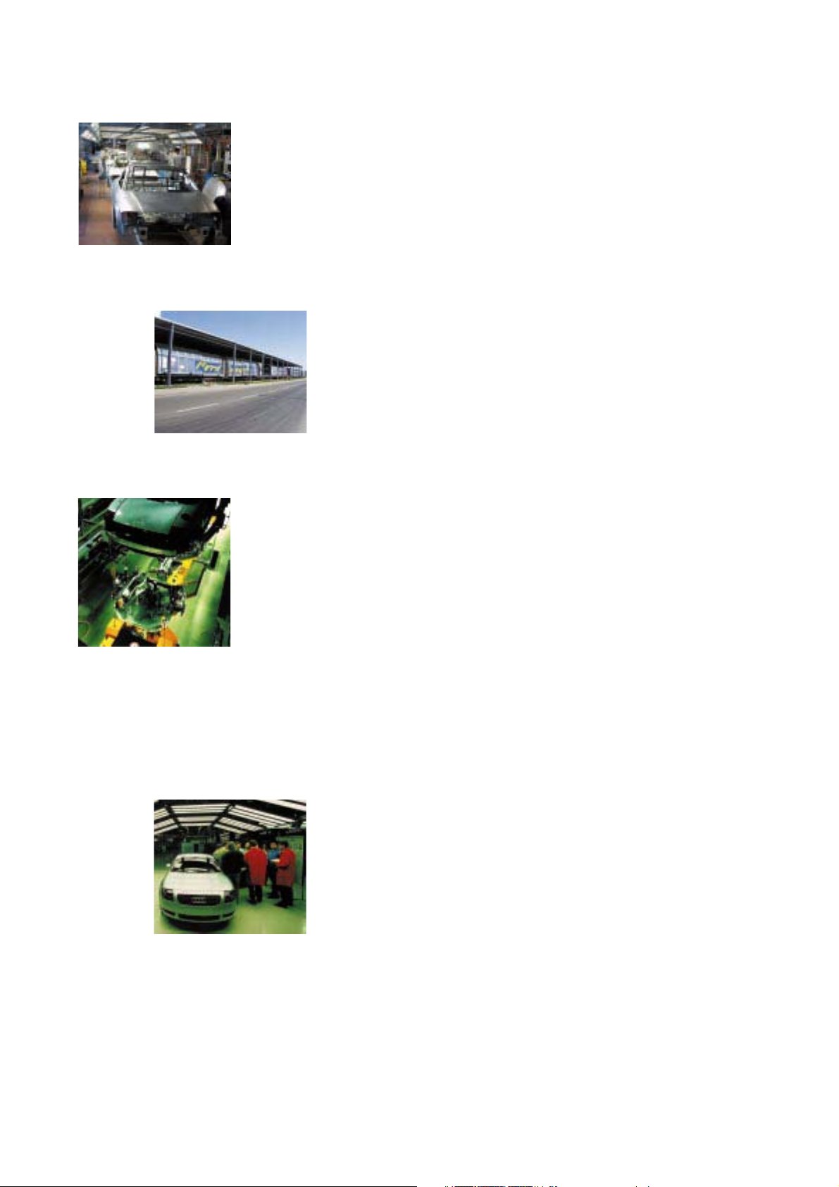
The plant – the plants
Ingolstadt plant
The model series Audi A4 and Audi A3 are produced in Ingolstadt.
A separate production line has been set up for the body in white of
the Audi TT Coupé.
The head office of Technical Development is also located in Ingolstadt.
Special trucks were developed for transferring the bodyshells to Györ for final assembly.
High-tech from Györ
Qualified specialists and a good infrastructure are key factors for the
Audi production shop in Györ.
Audi has been manufacturing four-cylinder 5V, V6 and V8 engines
here since 1997. Final assembly of the TT has also been taking place
here since 1998.
Axle and steering geometry measurement
Watertightness test
100% reliability is ensured through a series of systematic checks integrated in the production process.
Functional tests are an integral part of the production
process
Mounted parts are tested for accuracy of fit, build quality
and functionality after each stage of assembly.
Quality that is measurable
Electrical function test
Exhaust emission test and optimal setup
2
After final assembly, extensive tests and adjustments
are carried out on every single Audi.
Roller dynamometer
Acoustic test bench
Page 3

A brief introduction to the TT . . . . . . . . . . . . . . . . . . . . 4
Design needs no explanation
Vehicle dimensions
Vehicle identification
Environmentally-friendly production
Body . . . . . . . . . . . . . . . . . . . . . . . . . . . . . . . . . . . . . . . . 9
Special features
Vehicle safety . . . . . . . . . . . . . . . . . . . . . . . . . . . . . . . . 14
Occupant protection
Fuel cut-off
Drive units . . . . . . . . . . . . . . . . . . . . . . . . . . . . . . . . . . 18
Engine and gearbox combinations
1.8-ltr. 132 kW 5V turbocharged engine AJQ
1.8-ltr. 165 kW 5V turbocharged engine APX
Contents
Page
Subsystems of the Motronic . . . . . . . . . . . . . . . . . . . 37
Lambda control in the EUIII
Torque-oriented engine management
Accelerator position sender
Electrically-activated throttle valve
Fuel system . . . . . . . . . . . . . . . . . . . . . . . . . . . . . . . . . 42
Power transmission . . . . . . . . . . . . . . . . . . . . . . . . . . 48
5-speed manual gearbox
6-speed manual gearbox
Haldex viscous coupling
Running gear . . . . . . . . . . . . . . . . . . . . . . . . . . . . . . . . 56
Steering
Front axle
Rear axle
Brake system
Electrics . . . . . . . . . . . . . . . . . . . . . . . . . . . . . . . . . . . . 64
Vehicle electrical system
Interior monitoring
Immobiliser
Sound system
Heating/air conditioning system . . . . . . . . . . . . . . . . 76
Overview
Expansion valve
Service . . . . . . . . . . . . . . . . . . . . . . . . . . . . . . . . . . . . . 84
Flexible service interval indicator
Oil level sensor
Specifications
Special tools
The Self-Study Programme provides you with information
regarding design and function.
The Self-Study Programme is not a Workshop Manual.
Please refer to the Service Literature for all the relevant
maintenance and repair instructions.
New. Important.
Note.
3
Page 4
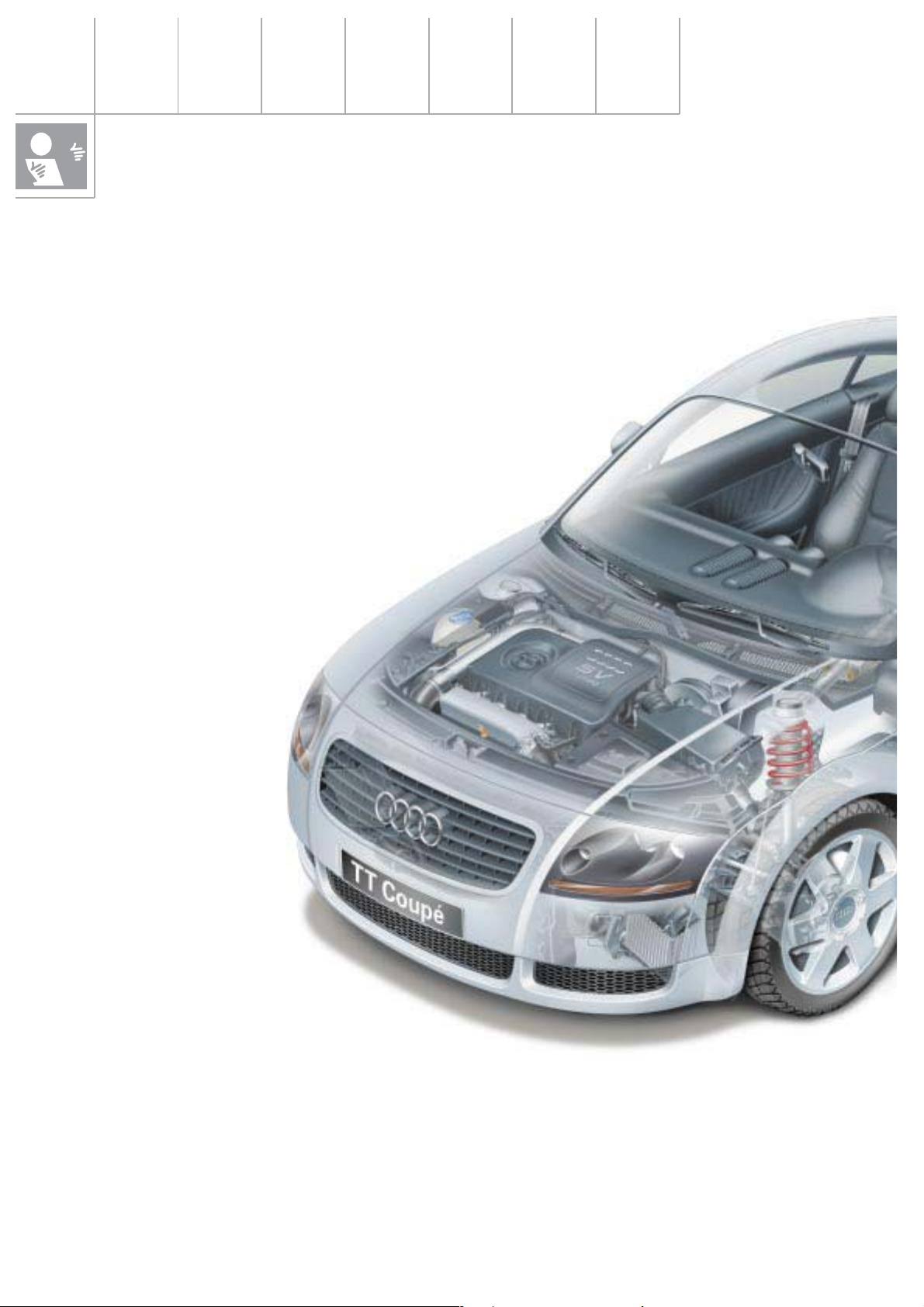
A brief introduction to the TT
Design needs no explanation
The name alone suggests that this is an Audi
with a difference. The Audi TT was named
after the legendary Tourist Trophy race on the
Isle of Man - the only one of its kind in the
world.
The Audi TT is equally as unique as its legendary namesake.
Engines
As befits a sports car, the Audi TT is
powered by a four-cylinder 5-valve
turbocharged engine developing
180 bhp with a sports gearbox in
the front-wheel drive and quattro
versions. A four-cylinder 5-valve
turbocharged engine
developing 225 bhp is
available for the
quattro version.
The interior styling matches the exterior perfectly - a fact reflected in the features of the
dash panel, the styling of the instruments, the
air nozzles and controls.
The styling of some parts has also been influenced by the use of aluminium.
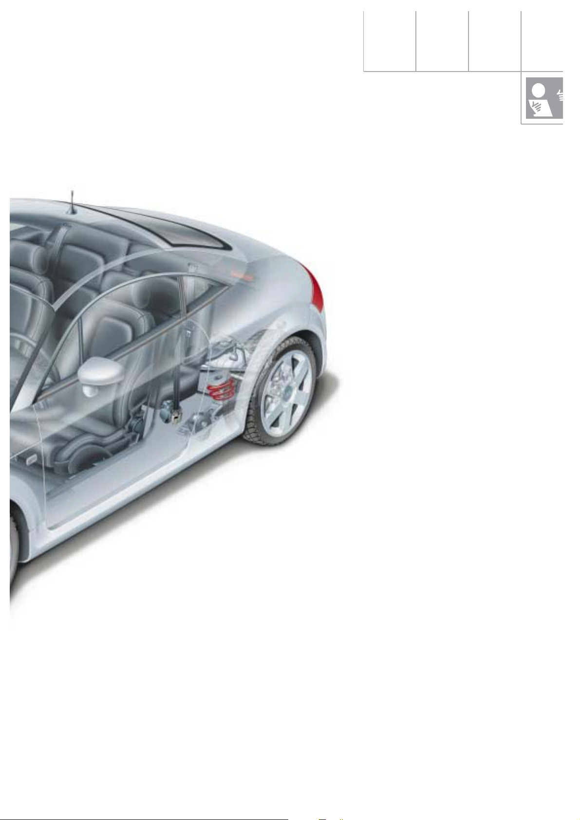
Running gear
The running gear also underscores Audi’s
total commitment to the sports car concept.
The front axle kinematics were revised with
regard to steering quality and response.
This, in combination with the Audi TT’s sporty,
stiff suspension tuning, ensures excellent
handling and a high standard of driving safety.
4
The basic version is equipped with 16-inch
wheels shod with size 205/55 R 16 tyres.
A 17-inch suspension is standard with the
quattro and available as optional equipment
for all other engine variants.
Page 5
There is no doubt that the real highlight of the
Audi TT is its emotive design, both on the
exterior and in the interior. The engineers at
Audi had an ambitious development goal: to
meet all functional and quality standards as
well as the latest statutory requirements and
Audi’s high standards of safety without compromising the design concept and while retaining the car’s full viability for everyday use.
SSP207/1
Safety
Safety is paramount:
That’s why the TT is equipped with front airbags for the driver and front passenger.
The TT already complies with the new European safety laws which will come into effect in
the year 2003 as well as the tougher requirements according to the US Head Impact Protection Act.
Quattro power train
The TT will feature a new generation of Audi
technology and the new Haldex viscous coupling, further emphasising the vehicle’s sporty
character.
Design
We at Audi firmly believe that the most
important thing about designing is that
actions speak louder than words. Suffice to
say, a good design speaks for itself.
The TT has a “wheel-hugging” design, that is
to say the entire body is styled around the
wheels. That also goes for the front and rear
bulges as well as the roof and window lines
and the low-slung passenger cabin.
5
Page 6
A brief introduction to the TT
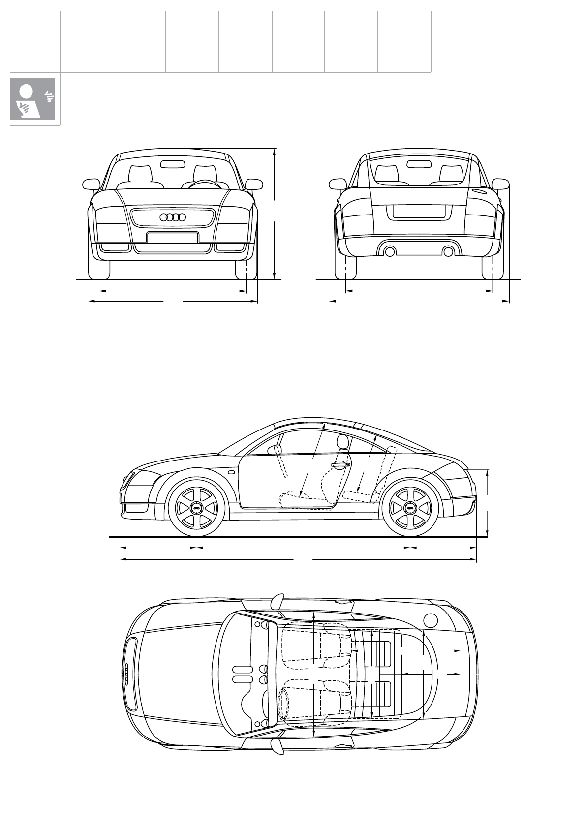
Vehicle dimensions
1354
1525
1764
The “+ and –“ dimensions are reference values compared to the Audi A3
Length: –111 mm
Width: +45 mm
Height: –69 mm
876
4041
1507 (quattro 1503)
1856
Track width
Front: +12 mm
Rear: +12 mm
+ 8 mm quattro
Wheelbase: –93 mm
–85 mm quattro
9
5
9
8
2
8
762
7462419 (quattro 2427)
(quattro 738)
1209
950
1412
1221
900
6
Page 7
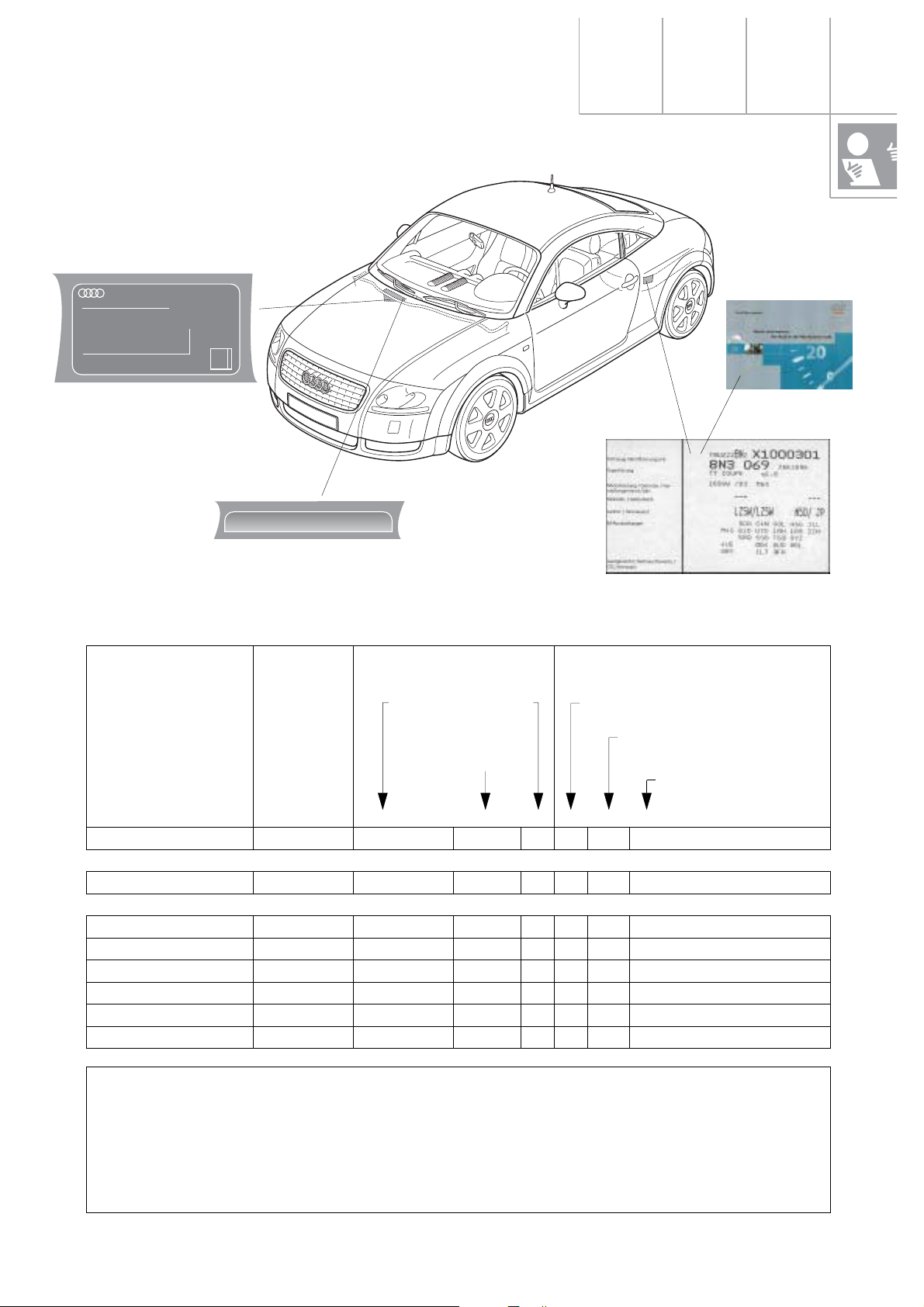
Vehicle identification
AUDI HUNGARIA MOTOR KFT
TRUZZZ8NZX1000301
1765 kg
kg
1 - 1015 kg
2 - 850 kg
Typ 8N
1
1000
2111008
TRUZZZ8NZX1000301
*
Key of manufacturing
plants within the Group
World manu-
facturing code
*
Part describing vehicle Part identifying vehicle
in digit position 11:
A Ingolstadt
N Neckarsulm
1 Györ
X Poznan
K Karmann/Rheine
Filler
constant = Z
Digits 1 + 2 vehicle
class. acc. to structure table
Model year, alphanumeric as prescri-
bed by law
Manufacturing plant within
the Group (as at 04/94)
Serial No. beginning
with:
1234567891011121314151617
Audi Hungaria Motor Kft:
TT/TTS *TRUZZZ8NZX 1 000001
Audi AG:
A3 *WAUZZZ8LZXA 000001
A4 *WAUZZZ8DZX A 000001
A6 (incl. SKD Poland) * W A U Z Z Z 4 B Z X N/X 000001
A8 *WAUZZZ4DZX N 000001
Cabrio *WAUZZZ8GZX K 000001
Audi 100 (C3, CKD) * W A U Z Z Z 4 4 Z X A 000001
* Vehicles to US specification
(USA, Canada, Saudi Arabia, tourists)
On the VIN (behind the windscreen), the certification label and on official documents, the fillers (Z) are replaced by a vehicle code (digits 4-8) or by a test mark (digit 9). This (18-digit) number is the official vehicle identification No. (VIN) in the countries listed above.
7
Page 8

A brief introduction to the TT
Environmentally-friendly
production
Produce locally - think global:
Environmental protection is firmly rooted in
Audi’s corporate strategy. During the vehicle
development process, all environmental criteria are incorporated into the product and production concept from the outset. Economic
goals and ecological needs are balanced so
that no conflicts of aims arise.
Audi lays great store by waste avoidance,
reduction and recycling.
– Almost all production resources and
supplied parts are delivered in re-usable
packaging.
– Most sheet-metal blanks are designed so
as to minimise cutting waste after
pressing.
Waste avoidance and reduction
From 1998 onwards, Audi will use only watersoluble paints in a effort to make its production process more environmentally-friendly.
This step will see a dramatic reduction in solvent emissions. Today’s fillers and base coats,
for example, contain up to 45% solvent. By
comparison, the solvent content in water-soluble systems is only about 6%.
8
Recycling
The recycling rate at Audi is now about 94%
by weight. Metal cuttings from the press plant
are used to manufacture small parts as far as
possible. The resulting scrap is returned to the
steelworks, where steel and zinc are separated
from one another.
Other waste materials such as paper, cardboard, timber, polystyrene, etc. are collected
separately and fully recycled .
Page 9
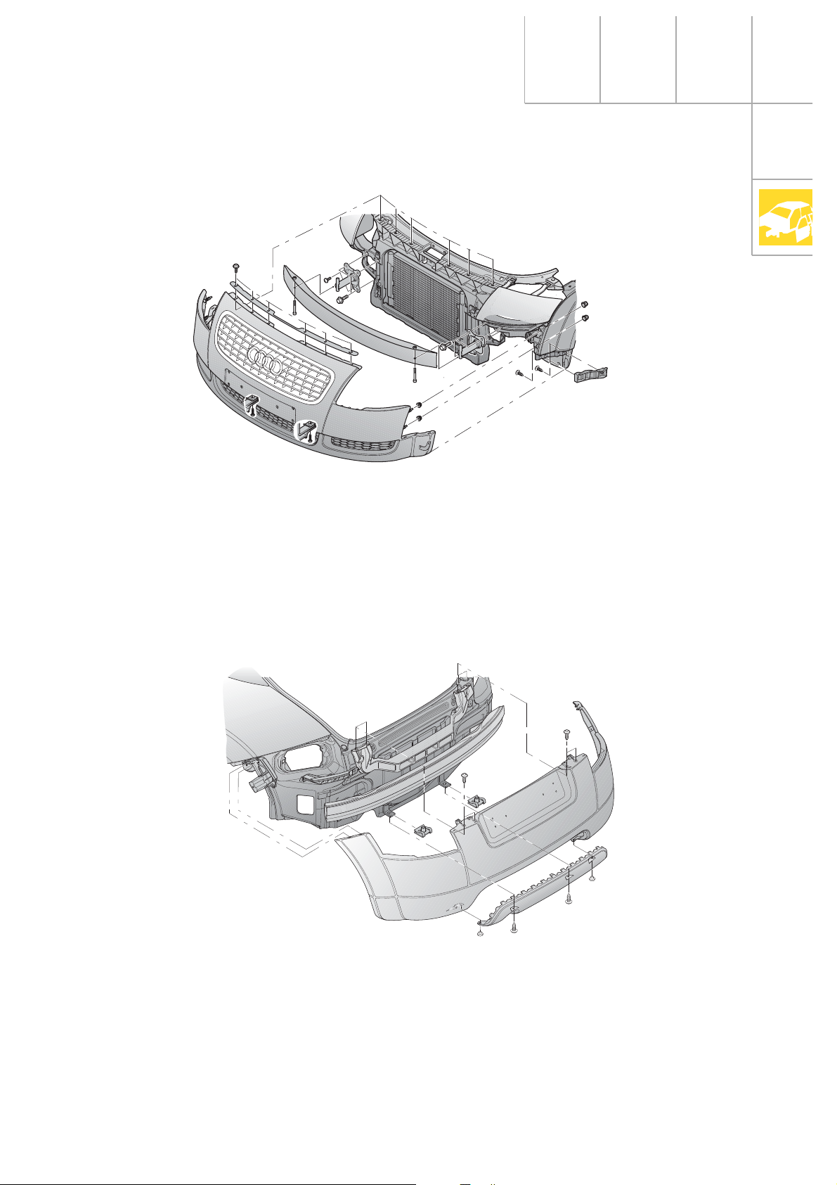
Special features
Front bumper
Body
SSP207/74
The front bumper comprises two parts: the
cover panel and a decorative grille. The bumper carrier is made of aluminium and bolted to
the side members by impact absorbing elements.
Rear bumper
The guide profiles attached to the left and
right wings ensure an even gap all round.
A zero joint is created by attaching the bumper to the wing by means of threaded bolts as
well as nut and washer combinations.
The rear bumper comprises a total of 4 parts:
the bumper panel, the rear cover, the aluminium cross-member and the central locating
element.
SSP207/75
The rear cover is available in two versions
depending on engine variant (TT has one
tailpipe, the TTS two). A seamless transition to
the body side section (zero joint) is produced
by means of 2 bolts on each body side section.
9
Page 10
Body
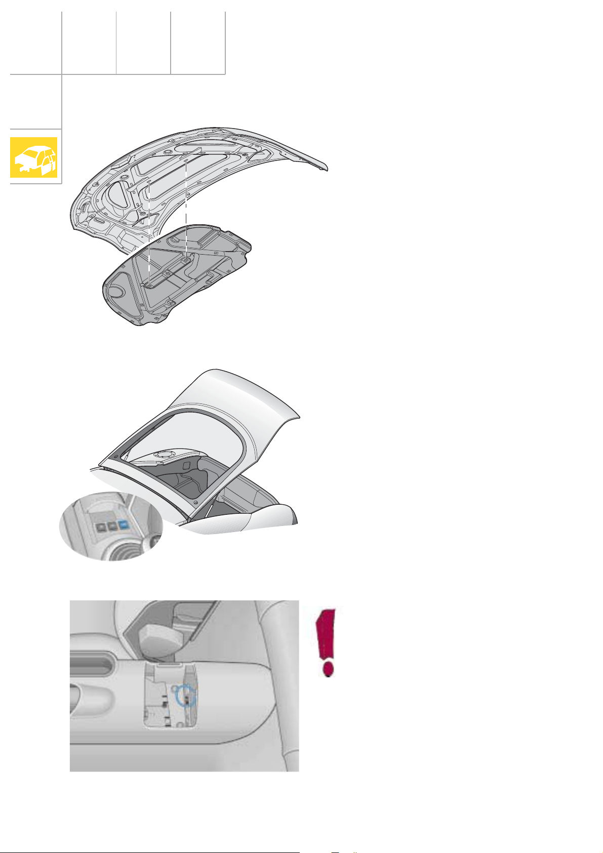
Bonnet
The bonnet is made of aluminium to save
weight.
SSP207/78
Tailgate
The tailgate can only be opened from the
interior by means of the switch in the central
console or by radio-wave remote control. The
tailgate does not have a lock cylinder or a
handle.
The tailgate has a single-joint hinge.
SSP207/77
If the electrical system fails, the tailgate can be released in an emergency
by means of the cable pull located
below the rear central console cover.
10
SSP207/76
Page 11
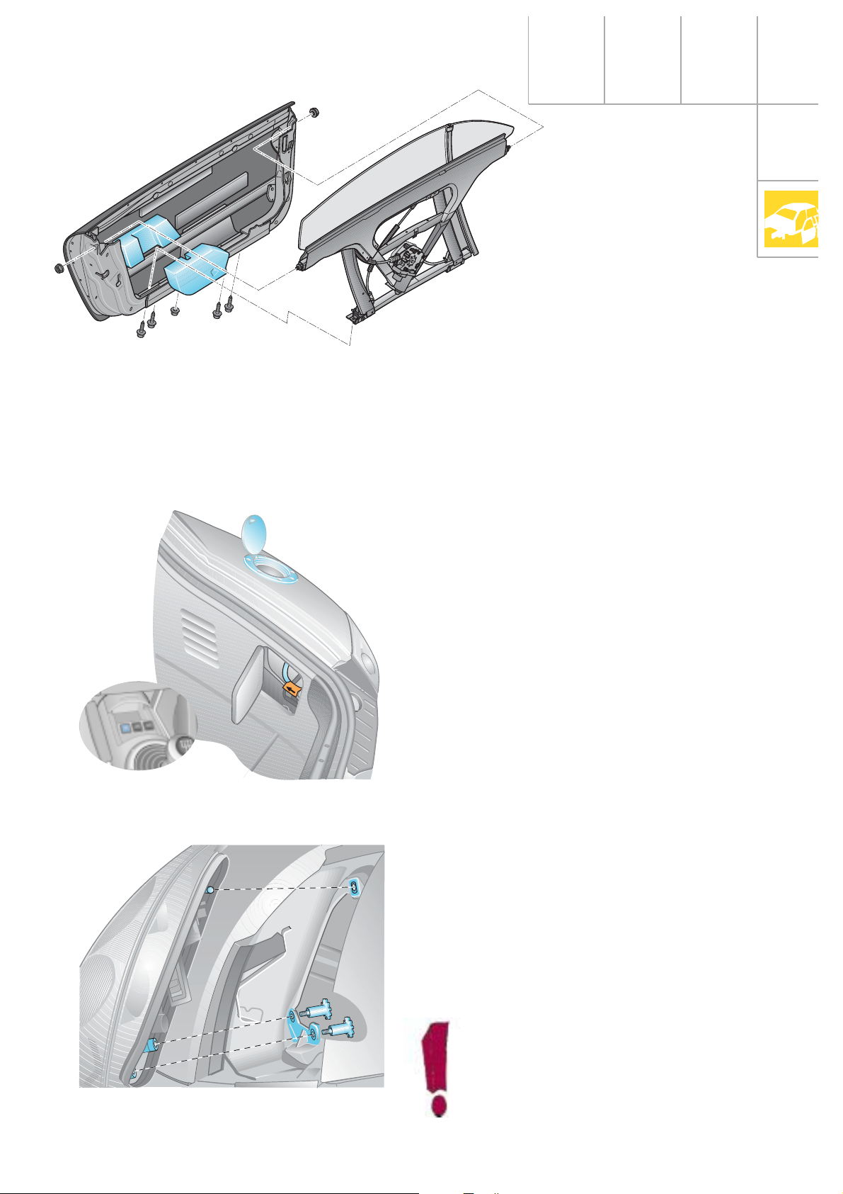
Doors
The doors of the Audi TT Coupé are frameless
and of two-piece construction.
The door panel is made of steel with a bolted
high-strength side reinforcement integrated in
the door.
SSP207/47
The door component carrier is made of aluminium and can be adjusted for length, height
and inclination.
Additional side protection pads protect the
pelvis area.
Fuel filler flap
Taillights
The fuel filler flap is made of aluminium. It can
only be opened electrically via a switch in the
central console.
The fuel filler flap is attached from the exterior
with three anti-theft-protected bolts plus four
decorative bolts.
If the electrical system fails, the fuel filler flap
can be opened via an emergency release
mechanism in the luggage compartment. For
this purpose, it is necessary to open the flap in
the side trim panel on the right-hand side of
the luggage compartment and pull the cable
in the direction indicated on sticker.
SSP207/72
To replace the filament lamps, the complete
taillight unit is removed without needing any
tools. Flaps are attached to the luggage compartment linings on the left and right. The
light cluster is secured on the inside by means
of 2 captive knurled bolts. On the outside, the
taillight is engaged in a ball head.
SSP207/56
The light cluster can be adjusted along
the vehicle’s longitudinal axis by
means of the threaded sleeves.
11
Page 12
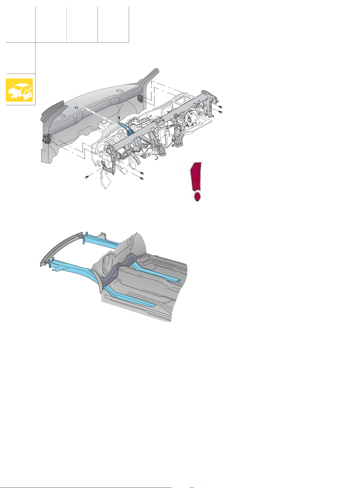
Body
Dash panel
SSP207/79
When removing the cross-tube,
please note that one of the fastening bolts is located on the outside
in the plenum chamber. To remove
this bolt, it is necessary to remove
the wiper linkage.
Structure
The vehicle front-end area deforms in a predefined manner, absorbing the impact energy
without impairing the stability of the occupant
cell. The side members are manufactured
from 2-, 3- and 1.5-mm-thick mash-welded
metal plates. In the case of a side impact, the
strong cross members will also deform on the
side of the body facing away from the impact
to absorb some of the impact energy.
SSP207/15
The body structure of the vehicle rear-end
area is designed in such a way that, firstly, the
integrity of the fuel system remains largely
intact and, secondly, the load on the
occupants is kept to a minimum even in
serious accidents.
The Audi TT Coupé therefore complies with
the statutory crash requirements as well as
the laws relating to frontal and side impacts
due to enter into effect in the EU and USA.
12
Page 13
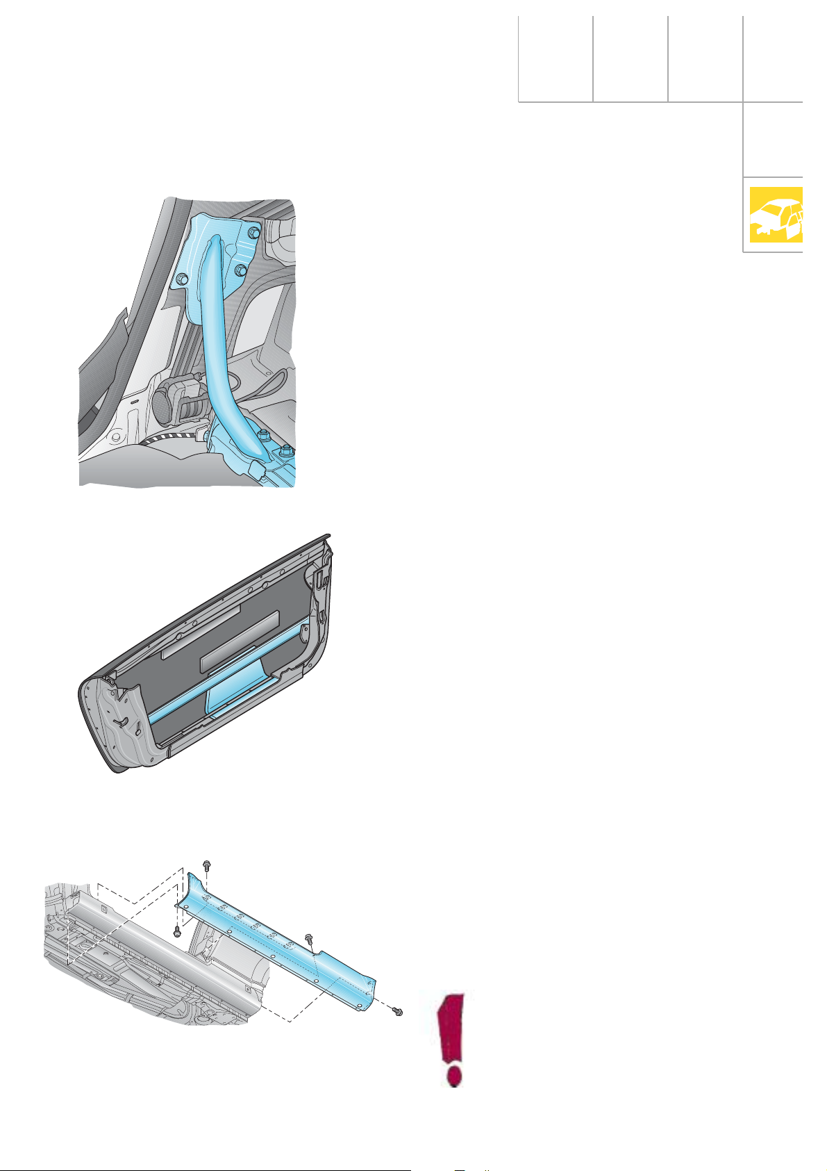
B-pillar
To absorb the load resulting from a side
impact, the body structure is extremely rigid
even though the B-pillar is not continuous. An
additional transverse support extending from
base of the B-pillar to the rear seat crossmember minimises cell deformation and the
rate of intrusion into the side structure. This
leads to low occupant loads.
Side reinforcements in the doors
Door sill
SSP207/9
SSP207/5
Since the deformation path for energy absorption is very limited during a side impact,
various design measures are necessary to perform this task effectively.
These include the side reinforcements made
of high-strength extruded aluminium sections
in the doors. The double-rectangular section
can absorb large mounts of energy .
During a side impact, the forces acting on the
vehicle are distributed via the side reinforcements in the doors to the sill and the A- and Bpillars.
The strong sill also absorbs energy and simultaneously transmits this energy to the stable
floorpan assembly.
SSP207/45
The sill trim is made of steel and is secured to
the sill with 17 bolt + washer combinations.
Be careful when placing the car on
a lift support, otherwise the door
sill may become dented.
13
Page 14
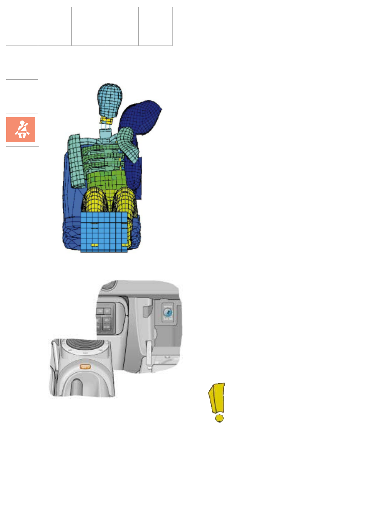
Vehicle safety
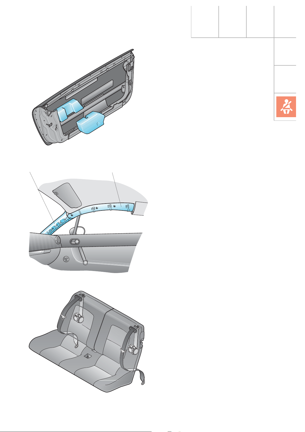
Occupant protection
The Audi TT Coupé has head-thorax side airbags for the driver and front passenger.
These side airbags are integrated in the seat
backrests and extend from the rib cage area
up to the head when inflated.
When the side airbag is tripped, the head and
neck areas are thus provided with better protection.
In the Audi TT Coupé, the belt tensioners can
be fired independently of the airbags depending on how the trigger criteria are defined.
SSP207/80
SSP207/81
The Audi TT Coupé has a disable function for
deactivating the front passenger airbag.
When using Reboard child seats on the front
passenger seat, the driver must disable the
front passenger airbag with the vehicle key via
the key switch located inside the glove box
(see Operating Manual Audi TT Coupé).
A yellow indicator light in the
central console indicates when
the airbag is deactivated.
14
Page 15
SSP207/6
During a side impact, the vehicle occupant is
inevitably subjected to a relative movement
towards the force application point and away
from the deformation path.
Therefore, it is very important to ensure that
the contact surface between the occupant and
the vehicle is large and energy-absorbing.
The side protection paddings made of plastic
foam protect the vehicle occupants in the pelvis and rib cage areas.
Deformation element Roof padding
SSP207/7
For protection of the head, a padding is also
integrated in the roof area.
An additional deformation element has been
welded onto the A-pillar.
These measures have enabled Audi to comply
with the new US head impact laws for the first
time.
The rear seat has been approved as a Group 3
child seat (approx. 6 - 12 years) and is compliant with ECE-R44. Children of heights ranging
from 1.30 m to 1.50 m without raised seat
swab.
SSP207/73
15
Page 16
Vehicle safety
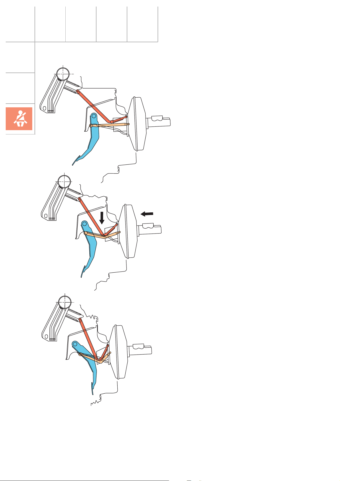
To minimise the risk of foot injuries in serious
head-on collisions, the brake pedal is swung
away from the foot area by means of a collapsing support if severe deformation of the
vehicle occurs.
This function is determined by deformation of
the engine bulkhead and is not dependent on
operation of the brake pedal.
In the event of a frontal crash, the foot controls are displaced towards the central tube.
This causes the collapsing support to deflect
and the piston rod to buckle.
16
The pedal footplate is swung up to 170 mm
away from the foot area.
The buckling of the piston rod and the deformation work resulting from this dampens the
angular movement of the braking foot. This
reduces the acceleration forces (braking foot)
which normally arise considerably.
SSP207/126
Page 17
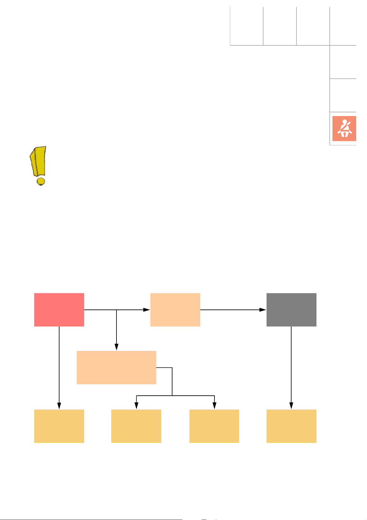
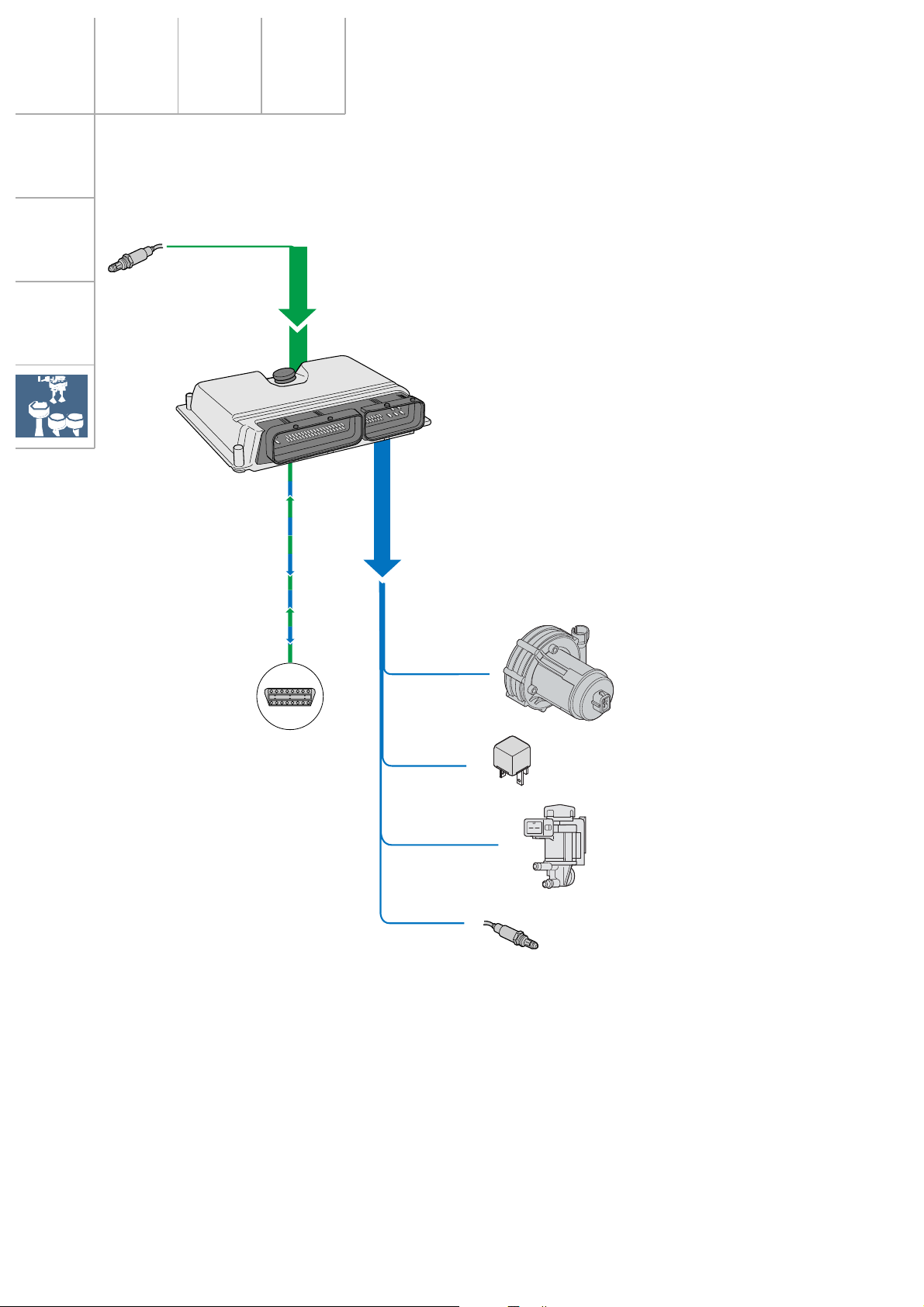
Fuel cut-off
The fuel tank is made of plastic and is housed
in a protected position in front of the rear axle.
The Audi TT Coupé is the first Audi to
be equipped with a fuel cut-off.
In connection with an airbag trigger
mechanism (crash signal output), the
Motronic control unit switches the fuel
pump off.
The central locking control unit receives this
signal simultaneously and unlocks the vehicle
doors. The hazard warning lights are activated
automatically and the interior lighting is switched on.
A restart function enables the engine to be
restarted after an accident and it can be
moved from the danger zone under its own
power.
J234 J220 J17
Airbag
control unit
Motronic
control unit
J379
Central locking control
unit and anti-theft
warning system
F220...223E3 G6
Hazard
warning
switch
Door locking
unit
Interior
lighting
Fuel relay
Fuel pump
17
Page 18
Drive units
Engine and gearbox combinations
Engine
1.8-ltr. 5V turbocharged
132 kW/180 bhp
Gearbox Code
MQ 250 5-speed front 02J.N
DZF
AJQ
SSP207/53
MQ 350 5-speed quattro 02M.3
DXW
SSP207/13
18
1.8-ltr. 5V turbocharged
165 kW/225 bhp
APX
SSP207/33
MQ 350 6-speed quattro 02M.1
DQB
SSP207/33
SSP207/14
Page 19
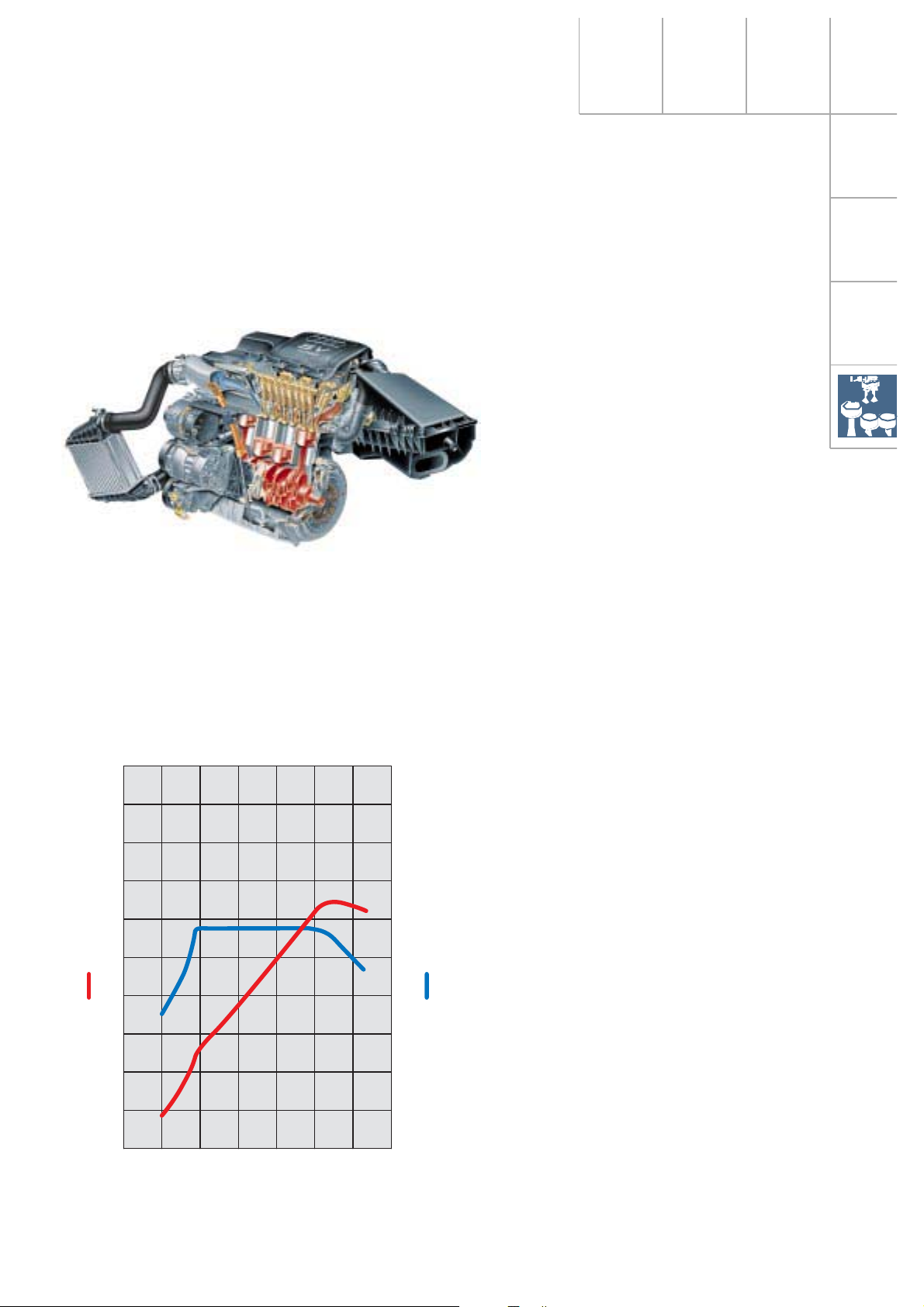
1.8-ltr. 5V turbocharged engine
132 kW AJQ
SSP207/13
Specifications
Engine code: AJQ
Type: 4-cylinder 5-valve
four-stroke petrol engine
with exhaust gas
turbocharger
Valve timing: Double overhead
camshaft (DOHC)
Displacement: 1781 cm
3
Bore: 81 mm
Stroke: 86.4 mm
Compression
ratio: 9.5 : 1
Torque: 235 Nm
at 1950 - 4700 rpm
Rated output: 132 kW/180 bhp
at 5500 rpm
Engine management: ME 7.5
Fuel: Premium unleaded 98 RON
(RON 95 can be used, but
reduces power output)
200
180
160
140
120
100
Output [kW]
80
60
40
20
0
1000
2000 3000 4000 5000 6000 7000
Engine speed [rpm]
SSP207/62
400
360
320
280
240
Torque [Nm]
200
160
120
80
40
0
Technical modifications:
Basic 110 kW (150 bhp)
– EU II + D3
– electronic throttle control
– “Tumble“ duct
(For details of the tumble duct in the intake
system, refer to SSP 198)
– Engine control unit (characteristic curves
adapted)
– CAN-BUS with TCS/EDL/ESP
– electr. activated air divert control valve
19
Page 20
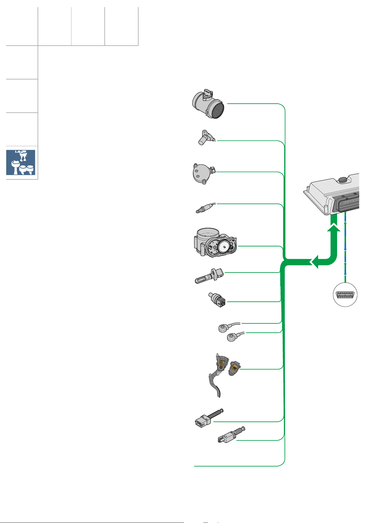
Drive units
System overview – 1.8-ltr. 132 kW 5V turbocharged
Sensors
Hot-film air mass meter G70
Engine speed sender G28
Hall sender G40
Lambda probe G39
Throttle valve control unit J338
with angle sender G187 for
throttle valve gear G186
Intake air temperature sender G42
Coolant temperature sender
G2 and G62
Knock sensor 1 (cyl. 1 - 2) G61
Knock sensor 2 (cyl. 3 - 4) G66
Accelerator pedal module with accelerator position sender G79 and G185
Brake light switch F and brake
pedal switch F47
Clutch pedal switch F36
Auxiliary signals:
Pressure switch for power steering F88
Cruise control
Intake manifold pressure sender G71
20
Page 21
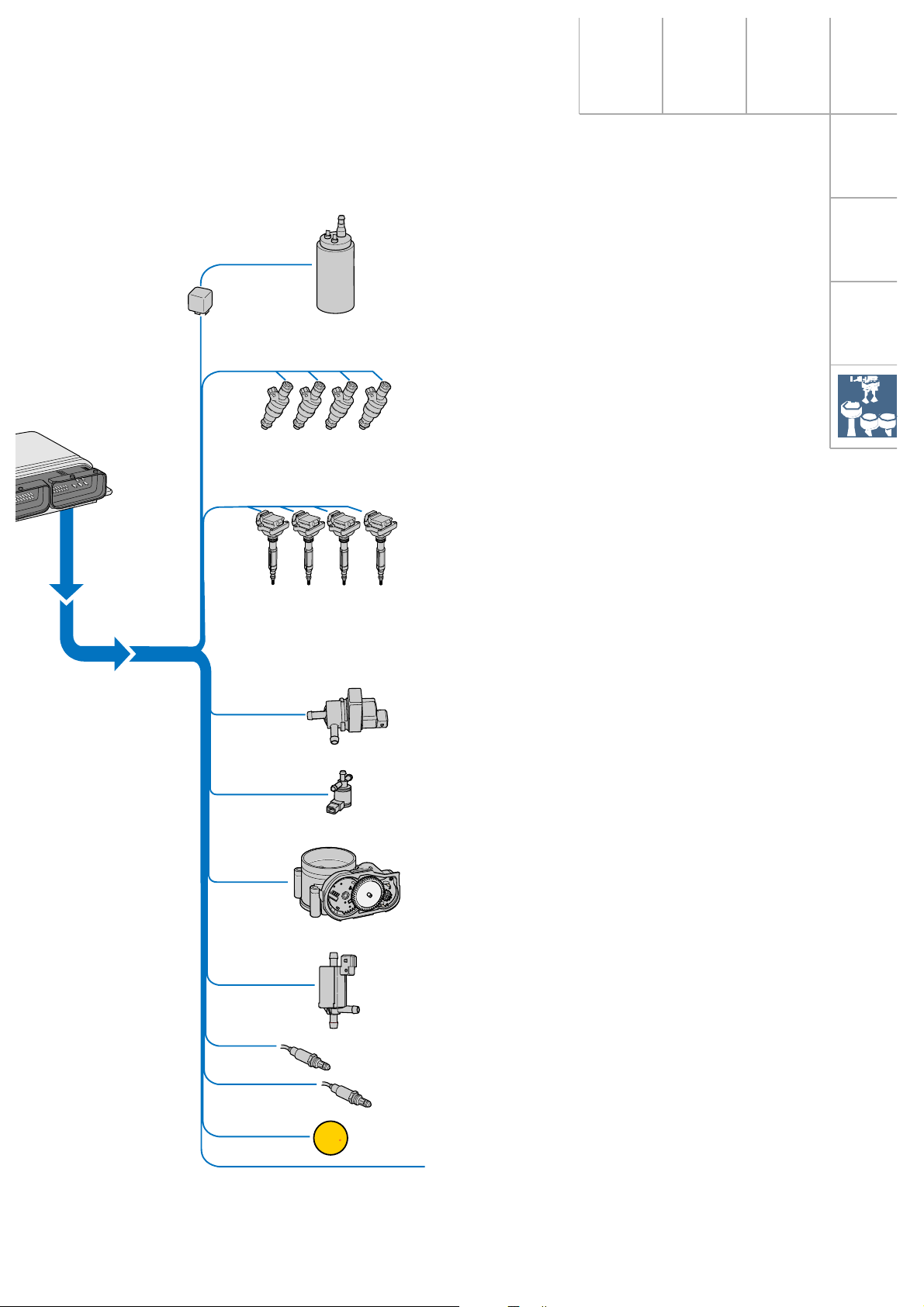
Actuators
Fuel pump relay J17 and
fuel pump G6
Injection valves N30, N31, N32,
N33
Power output stage N122 and
ignition coils N (1st cyl.),
N128 (2nd cyl.),
N158 (3rd cyl.)
and N163 (4th cyl.)
with integrated power output
stage
SSP207/46
EPC
Solenoid valve for activated
charcoal canister N80
Solenoid valve for charge pressure limitation N75
Throttle valve control unit J338
with throttle valve gear G186
Air recirculation valve for turbocharger N249
Heater for lambda probe Z19
Fault lamp for electronic throttle
control K132
Auxiliary signals
21
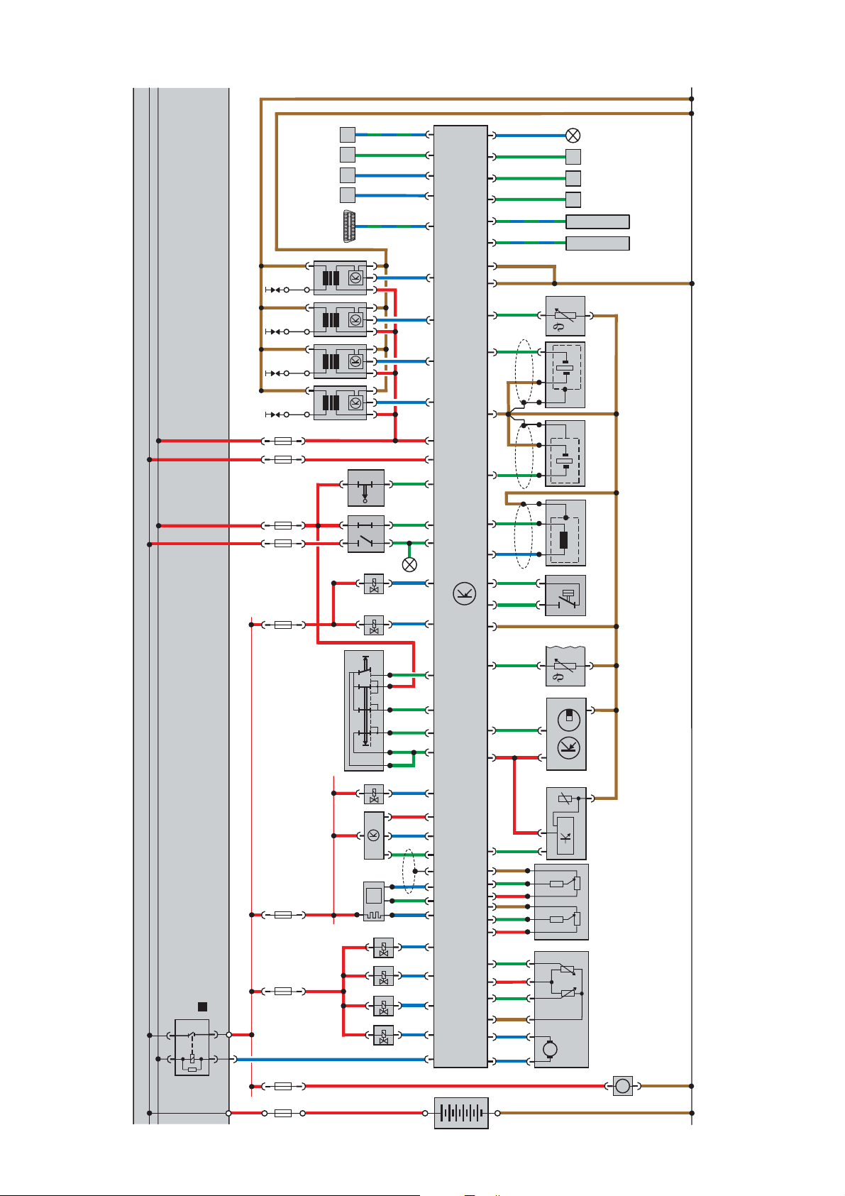
Page 22

Function chart
Turbocharged 1.8-ltr. 132 kW 5V engine
Motronic ME 7.5
Components
A Battery
E45 Switch for cruise control system
E227 Button for cruise control system
F Brake light switch
F36 Clutch pedal switch
F88 Power steering (pressure switch)
G6 Fuel pump
G28 Engine speed sender
G39 Lambda probe
G40 Hall sender with quick-start sender
wheel
G42 Intake air temperature sender
G61 Knock sensor 1
G62 Coolant temperature sender
G66 Knock sensor 2
G70 Air mass meter
G71 Intake manifold pressure sender
G79 Accelerator position sender
G186 Throttle valve gear
(electronic throttle control)
G187 Throttle valve drive angle sender 1
G888 Throttle valve drive angle sender 1
J17 Fuel pump relay
J220 Motronic control unit
K132 Fault lamp for electronic throttle
control
M9/10 Stop lights
N Ignition coil
N30...33 Injection valves
N75 Solenoid valve for charge pressure
limitation
N80 Solenoid valve for activated charcoal
canister
N128 Ignition coil 2
N158 Ignition coil 3
N163 Ignition coil 4
N249 Air recirculation valve for
turbocharger
P Spark plug socket
S Fuse
Q Spark plugs
Z19 Heater for lambda probe
Auxiliary signals
CAN-BUS H =
CAN-BUS L =
A Engine speed signal (out)
B Fuel consumption signal (out)
C Road speed signal (in)
D Air-conditioner compressor signal (in-out)
E Air conditioning ready (in)
F Crash signal (in) from airbag control
unit
G Alternator terminal DF/DFM (in)
W- line (in-out)
For the applicable Fuse No. and
amperage, please refer to the current
flow diagram.
Input signal
Output signal
Positive
Earth
Bidirectional
Databus drive
}
22
Page 23
23
Dieses Dokument wurde erstellt mit FrameMaker 4.0.4.
30
15
31
SSP207/25
DA
C
K132
G
B
Q
P
Q
P
N158 N163
Q
P
N128N
Q
P
SS SS
F36
F
N249
M9/10
E F
CAN - BUS L
CAN - BUS H
J220
J220
S
N75
E227E45
-
15 55 49 14 9
+
N80
G70G39
SSSS
λ
+
G40 G62 F88 G28 G61 G66 G42
-
G71
P
G79
Z19
N33
++
G188G187G186
N32N31N30
4
J17
3086
8785
+
30
15
A
--
+
-
A
M
G6
M
31
Page 24
Drive units
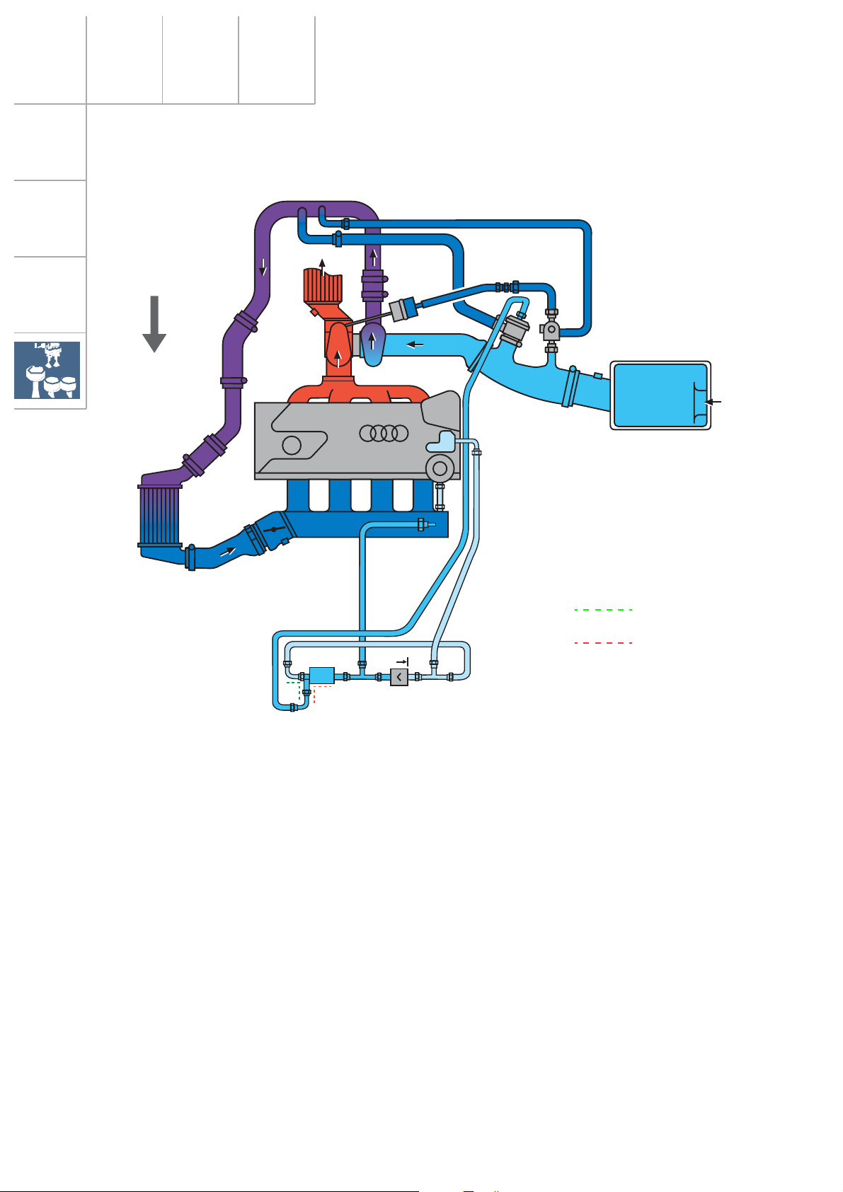
Charging
Direction of travel
5V Turbo
N249
The turbocharging system comprises the following components:
– Exhaust emission turbocharger
– Charge air cooler
– Charge pressure control
– Air divert control in overrun
The flow energy of the exhaust emissions is
transferred to the fresh air entering the exhaust
gas turbocharger. In the process, the air required
for combustion is compressed and the volume
of air entering the cylinders per working cycle is
thus increased.
The air temperature, increased by compression,
is again reduced in the charge air cooler. Since
the density of the cooled air is higher, the
amount of fuel-air mixture entering the engine is
greater, too.
energised
de-energised
SSP207/20
The result is an increase in power output for the
same displacement and engine speed.
In the case of the 1.8-ltr. 5V turbocharged
engine, turbocharging is also used to provide
high torque from the bottom end to the top end
of the rev band.
Charge pressure increases in proportion to the
turbocharger speed. The charge pressure is
limited to prolong the life of the engine. The
charge pressure control performs this task.
The air divert control prevents the turbocharger
slowing down unnecessarily if the throttle valve
closes suddenly.
24
Page 25
Charge pressure control
Waste gate valve
J220
N75
G70 G28 G69
5V Turbo
N249
The engine control unit calculates the charge
pressure setpoint from the engine torque
request.
The engine control unit regulates the charge
pressure as a function of the opening time of the
solenoid valves for charge pressure limitation
N75. For this purpose, a control pressure is
generated from the charge pressure in the compressor housing and the atmospheric pressure.
This control pressure counteracts the spring
pressure in the charge pressure control valve
(vacuum box) and opens or closes the waste
gate valve in the turbocharger.
In the de-energised state, the solenoid valve N75
is closed and the charge pressure acts directly
on the vacuum box. The charge pressure control
valve opens at low charge pressure.
energised
de-energised
SSP207/22
If the control fails, the maximum charge pressure is limited to a basic charge pressure
(mechanical charge pressure).
If the bypass is closed, the charge pressure rises.
In the lower engine speed range, the turbocharger supplies the charge pressure required to
develop high torque or the required volume of
air.
As soon as the charge pressure has reached the
calculated charge pressure, the bypass opens
and a certain quantity of exhaust gas is ducted
past the turbine. The turbocharger motor speed
decreases, and so too does the charge pressure.
For more detailed information regarding charge
pressure control, please refer to SSP 198.
25
Page 26
Drive units
Air divert control in overrun
Air recirculation valve
(pneumatic)
5V Turbo
N249
When the throttle valve is closed, it produces
a backpressure in the compressor circuit due
to the charge pressure still present. This causes the compressor wheel to decelerate
rapidly. When the throttle valve is opened, the
speed of the turbocharger must again be
increased. The air divert control in overrun
prevents turbo lag, which would otherwise
occur.
The air recirculation valve is a mechanically
activated and pneumatically controlled spring
diaphragm valve. It is also activated via an
electrically activated air recirculation valve for
turbocharger N249. This, in connection with
the vacuum reservoir, enables the air recirculation valve N249 to operate independently of
the intake manifold pressure. If the air recirculation valve fails, control takes place as a
result of the engine vacuum downstream of
the throttle valve.
energised
de-energised
SSP207/23
As soon as the throttle valve is closed, the air
recirculation valve briefly closes the compressor circuit.
The vacuum counteracts the spring in the
valve. The valve opens, and the compressor
and intake sides of the compressor circuit
close for a short period of time. There is no
deceleration of the compressor wheel.
When the throttle valve re-opens, the intake
manifold vacuum drops. The air recirculation
valve is closed by the spring force. The compressor circuit no longer closes briefly. Full
charger speed is available immediately.
For more detailed information regarding the
air divert control in overrun, please refer to
SSP 198.
26
Page 27
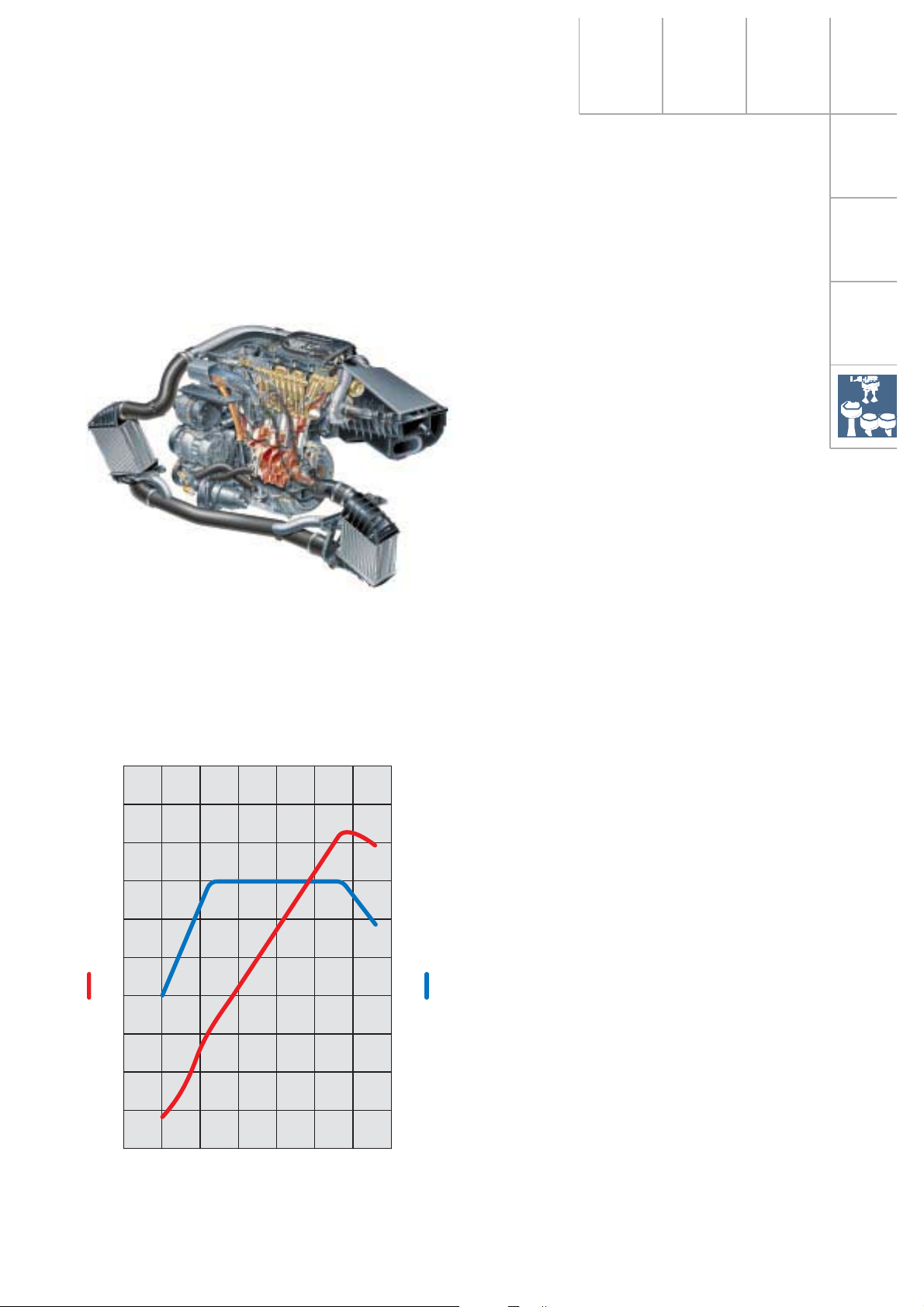
1.8-ltr. 5V 165 kW APX
turbocharged engine
SSP207/14
Specifications
Engine code: APX
Type: 4-cylinder 5-valve
four-stroke-petrol engine
with exhaust gas
turbocharger
Valve timing: Double overhead
camshaft (DOHC)
Displacement: 1781 cm
3
Bore: 81 mm
Stroke: 86.4 mm
Compression ratio: 9 : 1
Rated output: 165 kW at 5900 rpm
max. torque: 280 Nm at 2200 to
5500 rpm
Engine management: ME 7.5
Fuel: Premium unleaded 98 RON
Exhaust gas
treatment: Twin-flow catalytic
converter, one heated
lambda probe upstream
and downstream of the
catalytic converter
200
180
160
140
120
100
Output [kW]
80
60
40
20
0
1000
2000 3000 4000 5000 6000 7000
Engine speed [rpm]
SSP207/63
400
360
320
280
240
200
Torque [Nm]
160
120
80
40
0
Technical modifications:
Basic 132 kW (180 bhp)
– Cooling water afterrun pump (approx. 10 min)
– Secondary air system
– Piston (modified), thus changing the
compression ratio to 9.0 : 1 from 9.5 : 1
– Manifold (new exhaust and flange)
– When EU III takes effect, there will be a 2nd
lambda probe downstream of catalytic
converter for catalyst monitoring
– 2 in-line charge air coolers
– Injection valves (higher flow)
– Quick-start sender wheel
– Piston cooling by oil injectors
(volumetric flow adaptation)
– Hot-film air mass meter with reverse flow
detector HFM5 integrated in the intake air
filter upper section
– Single-flow throttle valve unit integrated in
the electronic throttle control positioner
27
Page 28
Drive units
Extended system overview - 1.8-ltr. 165 kW 5V engine
Lambda probe downstream of catalytic converter G130 when EU III
takes effect
Motronic control unit J220
SSP207/103
The secondary air system in the 1.8-ltr. 5V
engine developing 165 kW ensures that the
exhaust emissions comply with the EU III+D3
standard.
Secondary air pump motor V101
Secondary air pump relay J299
Secondary air injection valve N112
Heater for lambda probe
down-stream of catalytic
converter Z29
when EU III takes effect
A probe will be installed downstream of the
catalytic converter to meet the requirements
stipulated in EU III.
28
Page 29

Extended function diagram - 1.8-ltr. 165 kW 5V engine
30
Z29
J17
S
G130 N112
λ
S
J299 V101
M
J220
KH
As of series production launch, the 1.8-ltr.
165 kW engine will be equipped with extended
system components to ensure it complies
with European exhaust emission standard
EU II + D3.
The basic version is equivalent to the engine
management system used in the 1.8-ltr.
engine developing 132 kW (refer to function
diagram).
31
SSP207/27
Legend
G130 Lambda probe downstream of
catalytic converter when EU III comes
into effect
J17 Fuel pump relay
J299 Secondary air pump relay
N112 Secondary air injection valve
V101 Secondary air pump motor
Z29 Heater for lambda probe downstream
of catalytic converter when EU III
comes into effect
H Air conditioning PWM signal
K Fault lamp
29
Page 30

Drive units
Quick-start sender wheel
The quick-start sender wheel is attached to the
camshaft. It supplies a signal which enables
the engine control unit to determine the position of the camshaft relative to the crankshaft
more quickly and, in combination with the
signal which the engine speed sender supplies, to start the engine more quickly.
Twin-track sender wheel
On previous systems, it was not possible to
initiate the first combustion cycle until a crank
angle of approx. 600˚ - 900
quick-start sender wheel enables the engine
control unit to recognise the position of the
crankshaft relative to the camshaft after a
crank angle of 400˚ - 480
This allows the first combustion cycle to be
initiated sooner and the engine to start more
quickly.
Track 1
Track 2
o
Tooth
o
was reached. The
.
Hall device
Track 1
Hall device
Track 2
The quick-start sender wheel comprises a
twin-track sender wheel and a Hall sensor. The
sender wheel is designed so that two tracks
are located side by side. In the position where
there is a gap in one track, there is a tooth in
the other track.
Gap
SSP207/84
Hall sensor
30
Page 31

SSP207/85
The control unit compares the phase sensor
signal with the reference mark signal and thus
ascertains the working cycle currently taking
place in the cylinder.
Low phase signal = Compression cycle
High phase signal = Exhaust cycle
The signal which the engine speed sender G28
supplies enables the injection cycle to be
initiated after a crank angle of approx. 440
o
.
G40
J220
2
SSP207/86
Electrical circuit
The Hall sender G40 is connected to the sensor earth terminal of the engine control unit.
1
G71
Even if the Hall sender fails, it is still
possible to start the engine.
3
SSP207/87
31
Page 32

Drive units
Cooling circuit
Coolant afterrun pump
Expansion
tank
Coolant pump
Coolant regulator
Coolant temperature
sender G2/G62
Heating heat exchanger
Exh. gas turbocharger
Cylinder head
Coolant afterrun
pump V51
Cooler
The exhaust gas turbocharger is water-cooled
and integrated in the cooling circuit.
When the coolant regulator is open, the coolant flows back to the cooler or coolant pump
via cylinder head, exhaust gas turbocharger
and coolant afterrun pump, among others.
Oil cooler
Thermoswitch for
radiator fan F18/F54
SSP207/37
The coolant afterrun pump protects the coolant against overheating, e.g. after turning off
a hot engine.
32
Page 33

Coolant afterrun pump V51
The coolant afterrun pump V51 is attached to the radiator fan housing.
To counteract the thermal loads, and in particular at the exhaust gas turbocharger, the
pump V51 starts up when the ignition is turned “On“.
SSP207/38
Function in vehicle with air conditioning
The pump starts via radiator fan control unit
J293 when the ignition is turned “On“. A timer
module integrated in the control unit J293
ensures that the pump V51 runs on for
approx. 10 min after the ignition has been
switched off.
In vehicles without air conditioning, these
functions are implemented by means of a
timer relay.
33
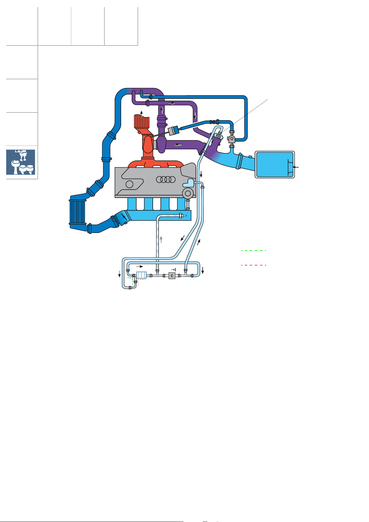
Page 34

Drive units
Charging
5V Turbo
To increase the power output and torque of
the 1.8-ltr. 5V engine to 165 kW, it was necessary to make various design modifications to
the basic engine of the Audi TT Coupé
developing 132 kW.
A characteristic feature of the engine is its
higher air demand, making it necessary to
enlarge the diameter of the intake port and
exhaust gas turbocharger.
SSP207/24
Since the previous charge air cooler was no
longer capable of effectively cooling down the
increased air flow through the exhaust gas
turbocharger, it was necessary to accommodate a second, parallel charge air cooler on
the left-hand side of the vehicle.
34
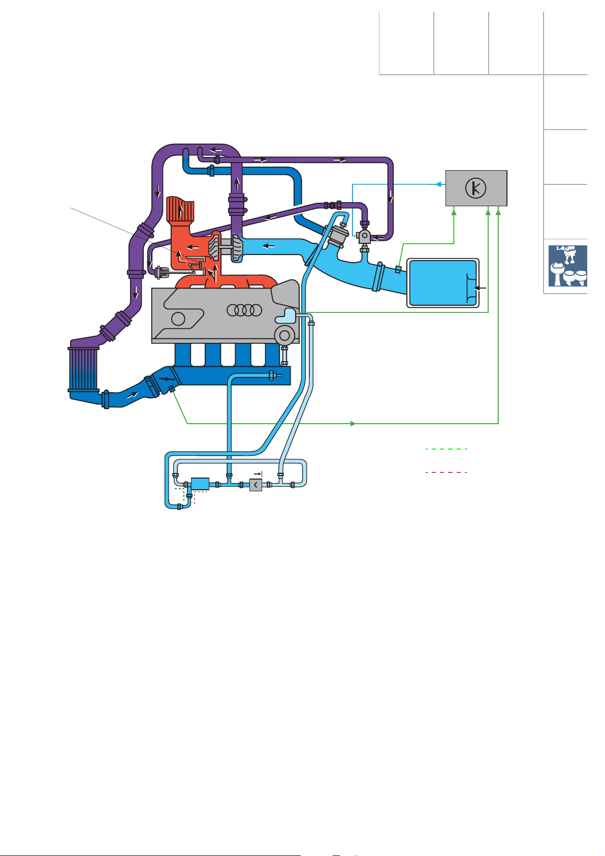
Page 35

Secondary air system
Vacuum box for charge
pressure control valve
Combi-valve
5V Turbo
energised
G39 G62
J299
N122
V101
J220
In the cold start phase, the exhaust
gases contain a high proportion of
uncombusted hydrocarbons.
To improve the exhaust gas composition,
these constituents must be reduced.
The secondary air system is responsible for
this task.
The system injects air upstream of the outlet
valves during this phase, thus enriching the
exhaust gases with oxygen. This causes postcombustion of the uncombusted hydrocarbons contained in the exhaust gases.
de-energised
SSP207/21
The vacuum box for the charge pressure control valve is controlled in the cold start phase
by the electro-pneumatic secondary air control valve N112 while the secondary air system
is in operation.
The control pressure acts on the turbocharger
waste gate, and the exhaust gas flow is routed
past the turbine wheel up to the upper load
range.
The hot exhaust gases help the secondary air
system to quickly heat the catalytic converter
up to operating temperature during the cold
start phase.
The catalytic converter reaches operating temperature more quickly due to the heat released
during postcombustion.
35
Page 36

Drive units
SSP207/16
SSP207/17
Secondary air injection valve N112
The secondary air injection valve is an electropneumatic valve. It is switched by the Motronic control unit and controls the combi-valve.
To open the combi-valve, the secondary air
injection valve releases the intake manifold
vacuum.
To close the combi-valve, the secondary air
injection valve releases atmospheric pressure.
Secondary air pump V101
The secondary air pump relay J299 which the
Motronic control unit drives switches the electric current for the secondary air pump motor
V101. The fresh air which is mixed with the
exhaust gases is drawn out of the air filter
housing by the secondary air pump and
released by the combi-valve.
The combi-valve
The combi-valve is bolted to the secondary air
duct of the cylinder head.
The air path from the secondary air pump to
the secondary duct of the cylinder head is
opened by the vacuum from the secondary air
injection valve.
Fresh air from
secondary air pump
Valve opened
Vacuum in control line
from secondary air
injection valve
This valve also prevents hot exhaust gases
entering and damaging the secondary air
pump.
Valve closed
Atmospheric pressure
in control line from
secondary air injection
valve
36
To secondary air
port
SSP207/19
Exhaust gas
SSP207/18
Page 37

Subsystems of the Motronic
Lambda control in EU III 165 kW
Lambda control in the EU III
An additional lambda probe (G130), which is
located downstream of the catalytic converter,
was integrated in the system to comply with
EU III. Its purpose is to test the function of the
catalytic converter.
Depending on vehicle type, the connectors,
plug colours and fitting locations are different
to help identify the connectors correctly.
SSP207/100
What is the purpose of the EU III test?
An aged or defective catalytic converter has a
lower oxygen storage capacity, which also
means that its conversion efficiency is poorer.
If the applicable limit values for hydrocarbon
content in the exhaust gases are exceeded by
a factor of 1.5 in the course of a statutory
exhaust emission test, this must be identified
via the fault memory.
Electrical circuit
J220
+
1
3
2
4
Catalytic conversion diagnosis
During the diagnosis, the engine control unit
compares the probe stresses upstream and
downstream of the catalytic converter probe
and calculates an upstream-to-downstream
ratio.
If this ratio deviates from the nominal range of
values, the engine management recognises
that the catalytic converter has malfunctioned.
After the fault conditions have been fulfilled,
the appropriate fault code is saved to the fault
memory.
Effects of signal failure
The engine lambda control also operates if the
probe downstream of the catalytic converter
fails.
The only function which is unavailable if the
probe fails is the catalytic converter function
test.
In this case, the Motronic cannot execute a
functional test on the probe upstream of the
catalytic converter either.
See SSP 175 – On-Board
Diagnosis II.
G130
SSP207/101
37
Page 38

Subsystems of the Motronic
Torque-oriented engine
management
The Motronic ME 7.5 has a torque-oriented functional structure.
The new electronic throttle control
function makes this possible.
External torque requests
• Driver input
External and internal torque requests are coordinated by the engine control unit, making
allowance for efficiency and implemented with
the available manipulated variables.
Internal
torque requests
art
•St
• Idling control
• Catalytic converter
heating
• Power output
limitation
• Driving comfort
• Component
protection
• Engine speed
limitation
Torque-influencing manipulated variables
38
• Driving
dynamics
• Driving
comfort
• Cruise control
system
Co-ordination of tor-
que and efficiency
requests in the engine
control unit
Throttle valve
angle
Charge pressure
Ignition angle
Cylinder suppres-
sion
Injection time
SSP207/96
Page 39

Torque-oriented
functional structure
In contrast to previously known systems, the
ME 7.5 is not limited to the output of torque
variables to the networked control units (ABS,
automatic gearbox). Instead it refers back to
the basis of this physical variable when it calculates the manipulated variables.
Charge path prio-
ritisation
All - internal and external - torque requests are
combined to form a nominal torque.
To implement the nominal torque, the manipulated variables are co-ordinated, making allowance for consumption and emission data so
as to ensure optimal torque control.
Charge torque
setpoint
Conversion of
torque into
charge
Throttle position
calculation
Setpoint charge
Throttle valve
angle
External and
internal tor-
que requests
Prioritisation of
crankshaft-syn-
chronous path
Actual charge
Calculation of
efficiency and tor-
que reference
variables
Calculation
of crankshaft-
synchronous
Inner torque
setpoint
Charge pressure
control
initiations
Intake manifold
pressure setpoint
Charge pressure
(waste gate)
Ignition angle
Cylinder sup-
pression
Injection time
SSP207/97
39
Page 40

Subsystems of the Motronic
Accelerator position senders G79
and G185
The accelerator position sender transmits the
driver inputs to the Motronic.
SSP207/102
G79
G185
Resistance in Ω
LHD
Accelerator pedal travel
Module housing
Housing cover
with sensors
The accelerator position sender transmits to
the Motronic an analogue signal corresponding to the accelerator pedal position. To
ensure the functional reliability of the electronic throttle control, the accelerator position
sender has two independent potentiometers
G79 and G185.
The characteristics are different (refer to diagram).
The control unit monitors the function and
plausibility of the two senders G79 and G185.
If a sender fails, the other sender acts as a
back-up.
Torque reduction Torque increase
• Traction control
• Engine speed limitation
• Speed limitation
• Power output limitation
• Cruise control system
• Driving dynamics control systems
40
The electronic throttle control function is used
to reduce and increase torque without adversely affecting the exhaust emission values.
SSP207/98
• Speed control
• Engine braking control
• Dash pot function
• Idling control
• Driving dynamics control systems
Page 41

Electrically actuated throttle valve
(electronic throttle control function)
With Motronic ME 7.5, there is no longer a
mechanical throttle control cable between the
accelerator pedal and throttle valve. This has
been replaced by an electronic control unit
(drive-by-wire).
The driver input at the accelerator pedal is
registered by the accelerator position sender
and transmitted to the engine control unit.
The system comprises the following components:
– Accelerator position sender
– Engine control unit
– Throttle valve control unit
Input signals Output signals
The engine control unit positions the throttle
valve via an electric motor. The engine control
unit is provided with continuous feedback on
the throttle valve position.
Extensive safety measures have been implemented in the hardware and software. For
example, dual senders, a safety module and a
self-monitoring processor structure are integrated in the electronic throttle control
function.
Throttle valve control
unit J338
Engine control unit
Throttle valve
drive G186
Accelerator position sender
SSP207/99
Accelerator pedal posi-
tion senders G79 and
G185
CPU*
* Control Processing Unit
Safety module
Angle senders for
throttle valve drive
G187 and G188
41
Page 42

Fuel system
Fuel tanks for vehicles with front-wheel drive
and quattro power train
Different fuel tanks are used in the front-wheel
drive and quattro versions of the Audi TT.
Both fuel tanks are made of plastic and have a
capacity of 55 ltr. and 62 ltr. in the front-wheel
drive and quattro versions respectively.
Air vent valve for vehicles with front-wheel
drive and quattro power train
Housing for gravity float valve
The filler neck cannot be separated from the fuel tank.
Bypass duct
Activated by
unleaded fuel
valve
Filler neck
Main expansion
chamber
When refuelling the vehicle, the unleaded fuel
valve activates the air vent valve. The valve
seals the main expansion chamber so that no
fuel vapour can escape from this tank when
the vehicle is being refuelled.
The filler expansion chamber is vented by the
filler neck.
Air vent valve
Filler expansion tank
SSP207/116
In the US version and after EU III
takes effect, fuel vapours will be
routed to the ACF system by an
additional vent line connected to
the air vent valve while the
vehicle is being refuelled.
42
Page 43

Gravity float valves for vehicles with frontwheel drive and quattro power train
Filler expansion chamber
Main expansion
chamber
to ACF system
The gravity float valve prevents fuel from
entering into the ACF system when cornering
at high speed or if the vehicle rolls over.
SSP207/117
The filler expansion chamber as well as the
main expansion chamber are combined at the
filler neck upper section and purged via the
gravity float valve by the ACF system.
43
Page 44

Fuel system
Fuel tank for front-wheel drive version
Gravity float valve
Filler neck
to activated charcoal filter
Air vent valve
Filler expansion
chamber
Main expansion chamber
Filler breather
Main breather
When refuelling the fuel tank, the gas mixture
is conveyed via the filler breather directly into
the filler expansion chamber and from here
via the filler neck into the atmosphere.
SSP207/118
The vapours are conveyed to the activated
charcoal filter via the closed filler neck, the
bypass at the air breather valve and the gravity float valve.
Heat-induced fuel vapours are channelled
through the operating vent and collected in
the main expansion chamber at the filler neck
upper section.
44
Page 45

SSP207/119
The fuel is transferred to the engine by a highperformance fuel pump with a pressure
increase from 3 to 4 bar.
In the event of a crash, the fuel pump is switched off by the fuel pump relay.
A single-stage fuel pump is used in vehicles
with front-wheel drive.
30
15
X
31
J220
G6
Electrical circuit
M
G
Components
30
G Fuel gauge sender
15
G1 Fuel gauge
X
31
G6 Fuel pump
J17
J17 Fuel pump relay
J218 Combi processor in dash panel insert
J220 Motronic control unit
S Fuse
S
G1
J218
31 31
SSP207/55
45
Page 46

Fuel system
Fuel tank for quattro vehicles
The breather system is designed in the same
way as for front-wheel drive vehicles.
Air vent valve
Filler expansion
chamber
Gravity float valve
Filler neck
Filler breather
Main expansion
chamber
Main breather
Located in the quattro fuel tank on the lefthand side is a suction jet pump which pumps
the fuel from the left-hand fuel tank part upstream of the baffle housing of the fuel delivery
unit.
46
SSP207/120
Page 47

SSP207/121
The suction jet pump is driven by the twostage fuel pump.
The suction jet pump can only be removed
after de-taching the fuel lines and tank sender
from the baffle housing.
Electrical circuit
30
15
X
31
J17
J220
S
G1
30
15
X
31
The fuel lines and left-hand tank sender are
connected to the baffle housing in the tank.
Components
G Fuel gauge sender
G1 Fuel gauge
G6 Fuel pump
G169 Fuel gauge sender 2
J17 Fuel pump relay
J218 Combi processor in dash panel insert
J220 Motronic control unit 2
S Fuse
G169
M
G6
31 31
G
J218
SSP207/82
The tank senders are connected in series.
R
+ R2 = R
1
total
Signals are evaluated in the dash panel insert
microprocessor.
The senders can be accessed via
two openings below the rear
seat.
For removing and installing the
senders, please follow the
instructions given in the Workshop Manual.
47
Page 48

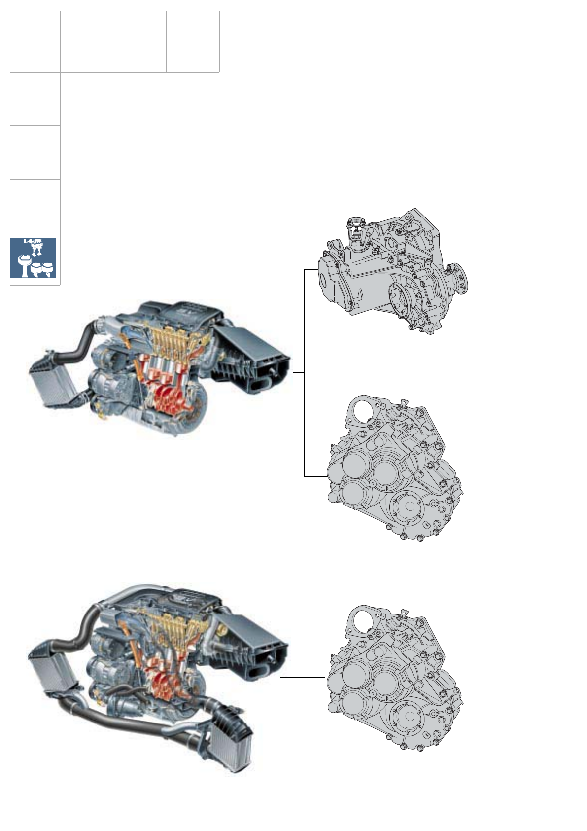
Power transmission
Three gearbox variants are used for power
transmission:
132 kW AJQ 5-speed front-wheel drive 2-shaft gearbox 02J.N
5-speed quattro drive
3-shaft gearbox
165 kW APX 6-speed quattro drive 02M.1
Technical features of the gearboxes
The 5-speed and 6-speed quattro gearboxes
are identical as regards their design, whereby
the change gear for 6th gear in the 5-speed
gearbox has been replaced with a spacer
sleeve.
4 manual shift gates are used for the 5- and 6speed variants (an optimal layout is possible
for both versions).
}
5-speed manual gearbox
Compared to the standard version (A3), the 5speed front-wheel drive version has a modified ratio, a re-inforced differential with flange
shaft adaptation and triple roller joint shaft.
The gearbox was modified in the selector
shaft area (standardised gear change linkages
used), and the gear lever of the sporty version
of the TT has been adapted.
02M.3
48
SSP207/124
Page 49

6-speed manual gearbox
3 shafts
The triple-shaft design permits a space-saving
and highly compact design.
A distinction is made between two gearbox
variants, the variant for vehicles with frontwheel drive and the variant for vehicles with
four-wheel drive (quattro). Both variants differ
from one another as regards their attachment
points and oil penetration points.
The use of magnesium as a housing material
results in a weight reduction of 30% due to its
lower density (aluminium has a density of
2.695 g/cm
1.738 g/cm
3
and magnesium has a density of
3
).
SSP207/54
49
Page 50

Power transmission
3-shaft gearbox MQ 350 in 6-speed version
Reverse gear
2nd drive shaft
Gears 5-6
1st drive shaft
Gears 1-4
Engine drive
Spur gear
SSP207/122
50
The spur gear is riveted to the differential. If repair work is necessary, the
spur gear must be bolts.
For more detailed information on the manual
gear-boxes, see SSP 205.
Page 51

Notes
51
Page 52

Power transmission
Haldex viscous coupling
The four-wheel power train used in the Audi
TT Coupé quattro is a logical progression on
the proven four-wheel drive concept.
A new feature of the power train is the slipdependent force distribution control on both
axles by means of a Haldex viscous coupling.
The manual gearbox transmits the engine out-
SSP207/28
put directly to the front axle and simultaneously via an angle gear and the propshaft to
the Haldex viscous coupling flanged to the
rear axle drive.
The rear axle drive is composed of the Haldex
viscous coupling, the axle drive and the differential.
SSP207/29
Advantages of the Haldex viscous coupling:
– Permanent four-wheel drive is fully
automatic for the driver
– Permanent four-wheel drive at engine
speeds higher than 400 rpm
– Controllable four-wheel drive system, the
characteristic curve is not constant
– High rear axle drive torque of up to
3200 Nm
The transmitted torque is dependent on the
speed difference between the front and rear
axles.
Also, the torque transmission parameters are
defined in the software (variable torque transmission control adapted to the driving situation).
– Acceleration with high directional stability
– Handling is neutral with a slight tendency
to understeer
– No restrictions on towing when the axle is
raised off the ground
– Communication via CAN-BUS
52
Page 53

The system configuration
Plate coupling
Coupling output end (rear
axle differential input)
Input end
(propshaft)
Working piston
The Haldex viscous coupling is accommodated in a closed housing and mounted in front
of the rear axle drive.
The input shaft and the output shaft are separate.
These shafts are connected via a plate coupling running in oil.
The coupling package comprises inner and
outer plates, which are connected to the input
shaft and output shaft respectively.
Arranged around the shaft at the coupling
input end are a working piston and two parallel annular piston pumps with a single annular
piston each.
Piston of
annular piston pump
SSP207/11
The housing is filled with oil and hermetically
sealed against the atmosphere.
The plate coupling which runs immersed in oil
represents a closed system.
It has its own oil circuit, hydraulic components, an electrohydraulic control valve and an
electrical control unit.
The system is electrically linked to the onboard CAN databus.
The rear axle is a rear differential.
53
Page 54

Power transmission
The hydraulics
Working piston
Two parallel annular
piston pumps
Pre-pressurising
pump
M
Input Output
Plate set
Cam disc
Safety valve
Control valve
Torque is transmitted to the rear axle drive by
means of the plate coupling .
The necessary coupling pressure is generated
via the two annular piston pumps. The annular piston (also known as axial piston) is
driven by an axial piston pump.
The speed at which this pump rotates is the
difference between coupling input and output
speeds.
An even pressure curve is ensured by three
phase-shifted pump strokes.
The annular pistons runs in floating bearings.
They are driven by the pressure generated by
the pre-pressurising pump (an electrically
driven gear pump).
Oil filling
SSP207/12
In the event of a breakdown, this means that
the vehicle can be towed without the engine
running and with the axle raised off the
ground.
Torque is developed at the coupling depending on the driving situation.
Pressure modulation is induced by means of
the control valve (hydraulic proportional
valve), whose opening cross-section is altered
by a slide valve.
The slide valve is activated by a rack and a
stepping motor.
The control unit together with its software are
located in the immediate vicinity of the stepping motor.
The pre-pressurising pump only operates if
the ignition has been turned on and engine
speed is greater than 460 rpm.
54
A safety valve opens at very higher inner pressure to prevent the coupling from being
damaged.
Page 55

The control system
Wheel speed front right > front left Wheel speed rear right > rear left
Low coefficient of friction
Engine control unit
M
B
M
A
M
d
ABS/EDL
hydraulic unit
Motive force, front
ABS/EDL control unit
M
A
The Haldex viscous coupling does not have
any sensors of its own apart from a temperature sensor (necessary for compensating for
temperature-dependent oil viscosity).
The system conditions the signals which the
CAN-BUS supplies (ABS/EDL control unit,
engine control unit).
These are
– speed of each individual wheel
– engine torque
– engine speed
– driving condition (straight-ahead driving,
thrust, braking, ABS)
– accelerator pedal position/throttle valve
The control system can recognise corners,
manoeuvring mode, acceleration phase and
different wheel circumferences. The stiffness
of the Haldex viscous coupling is adjusted
according to the recognised driving conditions.
Motive force, rear
High coefficient of friction
Legend
ABS/EDL sensor line
ABS/EDL control line
Brake line, pressurised
Brake line, depressurised
M
M
M
A
B
d
Drive torque per wheel
Brake torque per wheel
Engine torque
Accelerator pedal position,
Engine torque,
Engine speed
Wheel speeds
If faulty signals are generated or if CAN messages cannot be received, the vehicle switches
to emergency mode.
If speed signals are missing, the coupling is
opened fully for safety reasons.
The Haldex viscous coupling is integrated in the vehicle self-diagnosis.
Address word: 22 – 4wd electronics.
M
M
Haldex
control
A
A
unit
Haldex
viscous
coupling
SSP207/10
55
Page 56

Running gear
Steering
The safety steering column is adjustable for
rake and reach as standard.
The maintenance-free rack and pinion steering
gear is power-assisted. The steering gear
stroke is transmitted directly to the swivel bearing due to the fact that the track rods are optimally attached to the steering arm.
Consequently, the steering is direct.
A steering damper reduces the influence of
impacts and vibrations which are transmitted
from the wheels to the steering gear.
56
SSP207/2
The vibration-optimised attachment of the
steering column to the dash panel cross-member keeps the steering wheel free of undesirable vibrations.
Page 57

Pressure switch for power steering
This is how it works:
The pressure switch for power steering is
located on the vane pump. It informs the
engine control unit when the vane pump is
subjected to a load.
The vane pump is driven by the engine by
means of a the ribbed V-belt. At full steering
lock, the vane pump generates a pressure.
This also places a higher load on the engine,
and idling speed can drop sharply. The signal
which the pressure switch generates enables
the engine control unit to recognise engine
loading in time and to regulate engine torque
at idling speed.
SSP207/113
As steering forces increase, the pressure
switch closes and sends a signal to the engine
control unit.
Without steering wheel movement, the pullup integrated in the engine control unit is at
+5 V.
When the pressure switch is closed, the
engine is connected to earth.
Electrical circuit
F88
12
The ME 7.5 determines itself how engine torque is to be increased at idling speed, in order
to counteract the load (e.g. ignition angle correction towards “retard“).
Components
J220 Engine control unit
F88 Pressure switch for power steering
J220
SSP207/83
57
Page 58

Running gear
Front axle
Incorporating double wishbones, subframe
and transverse anti-roll bar, the McPherson
strut axle is designed as a sports suspension.
Coupling link between suspension
strut/anti-roll bar
Track rod joint
To enhance track stability, newly developed
cast steel-swivel bearing with modified track
rod attachments as well as a new forged
cross-member are used.
Subframe
Ball joint
Steering gear
The features of the front axle are:
– Track rod joints (larger diffraction
angle)
– Ball joint is reinforced by thicker
journals
– The subframe is rigidly bolted to the
aluminium bush
– The suspension strut attachment to
the anti-roll bar ensures better
response
SSP207/3
58
Page 59

Rear axle
Front-wheel drive
Torsion beam axle with anti-roll bar
Wheel housing support
Wheel bearing
Double ball
bearing
requiring no
adjustment
Positioning
inclined 25
o
25°
25°
– Track width: 1507 mm
– Modified axle plates for increased camber
and modified toe-in
– Track-correcting axle bearing
The self-steering effect of the rear axle is more
favourable thanks to the bearing inclination
o
of 25
.
Due to the rear axle inclination, the side forces
which occur when cornering are transmitted
favourably to the bearing and from the bearing to the body.
SSP207/115
The shock absorbers are supported in the
wheel housing and the coil springs are supported below the side member.
The axle is stabilised by a tubular anti-roll bar.
Due to the separate layout of the
springs and shock absorbers, the vehicle has a large luggage compartment
and driving noise inside the passenger
cabin is reduced (sound insulation).
59
Page 60

Running gear
Rear axle
Quattro drive
Dual link trailing arm axle (DLTA) with Haldex
viscous coupling
Damper
Anti-roll bar
Subframe
Rubber bearing
– The dual link trailing arm axle is fixed via
the subframe (4-point attachment) and
each of the track-correcting wishbones
attached to the trailing link.
– For stabilisation purposes, a transverse
anti-roll bar is located on the axle
subframe.
– Fitting position of damper (approx. 45
Haldex viscous
coupling
Trailing arm
o
)
Trailing link
New tool for mounting rear wheel bearings.
SSP207/4
60
Page 61

Brake system
132 kW
Diagonal-split dual circuit brake system
Anti-lock Braking System (ABS) with elec-
tronic brake force distribution (EBFD)
Traction Control System
(TCS)
Disc brakes at front and rear
Ventilated at front Ventilated at front and rear
Brake servo
10“ 10“
165 kW
– The electronic brake force distribution
(EBFD) regulates the brake pressure acting
on the rear wheels via the ABS control unit
so that they cannot be overbraked.
The EBFD control is suppressed when the
ABS control takes effect.
– The electronic differential lock (EDL)
provides assistance with driving away on
slippery surfaces.
SSP207/42
Spinning wheels are braked automatically
and the drive torque is diverted to the
wheel which has traction.
– The Traction Control System (TCS)
prevents the driven wheels from spinning
by reducing engine torque (by adjusting
the ignition angle and intermittently
switching off the injection valves).
61
Page 62

Running gear
Anti-lock Braking System
ABS ITT/Mark 20 IE
G45
V64
N55
G47
For a brief description of the
components, please refer to
function diagram
J104
Brake circuit
Brake circuit
K14/33K47
F
Output signals
Input signals
G44
G46
SSP207/31
The basis of the ABS system is a dual-circuit
brake system. The brake circuits are laid out
diagonally and supply the front left, rear right,
front right and rear left wheels.
A separate brake line running from the 4-channel system of the hydraulic unit is assigned to
each wheel.
62
The EBPD is entirely software-supported and
does not require any hardware.
Fault recognition in the
ABS system is via
warning lamps (visual
contact) and by means
of the self-diagnosis
(diagnostic unit).
Page 63

Electronic stability brake system - ESBS
The electronic stability brake system improves
the track stability and steerability of braked
vehicles by applying each brake as required.
SSP207/94
It utilises the sensors and actuators of the ABS
system.
ESBS is a software development in the ITT
Mark 20 IE control unit.
Understeer
If a vehicle understeers during a braking operation, this means that the maximum cornering grip of the wheels has been exceeded.
The vehicle will slide towards the outside of
the corner over the front axle.
The ABS control unit recognises this situation
from the circumferential speed of the wheel.
The brake pressure acting on the front axle is
thus reduced in order to increase cornering
grip. The vehicle stabilises itself and follows
the direction in which the vehicle is
steered.
Brake application
Vehicle movement when
understeer occurs
SSP207/95
Brakes application
Vehicle movement when
oversteer occurs
Vehicle vertical axis
Yaw moment
Counteracting yaw
moment
Oversteer
If the vehicle oversteers during a braking operation, this means that the maximum cornering grip of the rear wheel has been exceeded.
The vehicle breaks away towards the outside
of the corner over the rear axle.
The ABS control unit recognises this situation
from the reduced circumferential speed of the
rear wheels and reduces the braking force
acting on the wheels on the inside of the corner. The guide forces acting on the inner
wheels are increased and thus stabilised.
A functional fault of the ESBS can neither be diagnosed nor rectified, since the
driving dynamics cannot be reconstr
ucted with workshop equipment.
63
Page 64

Electrics
The vehicle electrical system
The electrical/electronic connector stations as
well as the necessary control units are decentralised to meet the requirements.
This ensures an optimum wiring configuration.
Socket (power windows,
radio, CLS-ATA light, mirror
adjustment)
Lateral acceleration sensor, passenger’s side
Navigation operating electronics control unit J402
Immobiliser control
unit J362
Combi processor in the
dash panel insert J218
Airbag control unit J234
Connector point, A-pillar
Engine control unit J220
Radiator fan control
unit J293
64
Fuse box, battery
ABS-EDL control
unit J104
Page 65

Telephone operating
electronics control unit
J412
Control unit for headlight
range control J431
Central locking
control unit J429
Control unit for navigation
system and CD J401
M
i
c
r
o
-
Z
E
Coupling point, A-pillar
Mini-electrics
Lateral acceleration sensor, driver’s side
Socket (power windows,
loudspeaker, radio, central
locking, anti-theft alarm)
Fuse carrier
SSP207/112
65
Page 66

Electrics
Interior monitoring
The vehicle interior is monitored by an ultrasonic monitoring system.
It gives the alarm audibly via the horn of the
anti-theft warning system and visually via the
hazard warning lights.
The following requirements must be fulfilled
to ensure that the interior monitoring
functions properly:
– The vehicle must be closed on all sides
– There must be no additional air movement
in the vehicle interior
The system is safeguarded against false
alarms, e.g.:
– knocking on the roof of the vehicle or
against the window
– air movement caused by wind or passing
vehicles
– temperature changes, e.g. due to the
interior of the vehicle heating up as a result
of exposure to strong sunlight
– any kind of noise (horns, sirens, bells).
The system communicates with the anti-theft
warning system regarding activation/deactivation as well as tripping of the alarm.
Located on the central console is the interior
monitoring switch. It switches off the interior
monitoring for a single locking operation.
Alarm horn
Sensor module
Central locking
control unit
SSP207/68
Interior monitoring
switch
66
Page 67

Functional description
SSP207/69
The sensor unit comprises a sender, a receiver
and the evaluation electronics. The sensor
unit is located behind the interior lighting in
the vehicle headliner.
In its activated state, the transmitter module
sends out sound waves at a frequency of
40 kHz (imperceptible to the human ear) and
receives the echo a short time later via the
receiver module. The evaluation electronics
detects irregularities in the ultrasonic field and
sends an “alarm“ signal to the central locking
control unit.
The anti-theft warning system LED indicates
that the system is on standby.
Electrical circuit
+
30
J429
24
G209
13
K
SSP207/67
G209 Ultrasonic sensor for ATWS
J429 Central locking control unit
PIN1 K-diagnosis line
PIN2 Positive supply 12 V
PIN3 Earth
PIN4 Sensor signal “Activate alarm/signal“
Self-diagnosis
Address word for self-diagnosis: 45
The interior monitoring sensor unit only has
diagnostic capability when deactivated.
Only one bi-directional communication line is used to activate and trigger
the alarm.
For more detailed information regarding the
anti-theft warning system/interior monitoring,
please refer to SSP 185.
67
Page 68

Electrics
The immobiliser
is an electronic anti-theft protection device of
the 3rd generation and will be gradually phased into the Audi TT. It prevents the vehicle
from being operated by unauthorised persons
by intervening in the engine control unit.
The aim of the 3rd generation immobiliser is
to incorporate the engine control unit actively
into evaluation and monitoring processes.
W
SSP207/88
The 3rd generation immobiliser differs from
the previous immobiliser in the following
respects:
– Variable code evaluation in the engine
control unit and immobiliser control unit.
The engine control unit has an equation
which calculates the generated variable
code in the same way as in the immobiliser
control unit.
After teaching in the electronic module
of the key transponder once, the
immobiliser key is paired up with the
immobiliser and cannot be used for
any other immobiliser.
The components of the immobiliser are as follows:
90
50
30
40
20
10
50
60
70
1/2
0
130
°C
1/1
80
100
120
70
60
50
40
!
30
20
10
0
140
ABS
P
AIR
BAG
160
180
200
220
240
260
– The immobiliser control unit is integrated
in the dash panel insert.
– The warning lamp in the dash panel insert
– The reading coil on the ignition lock
SSP207/90
– The adapted ignition key
– The engine control unit
Always use the corresponding Workshop Manual when carrying out
repairs.
68
SSP207/89
Page 69

Functional description
After turning on the ignition, the key transponder sends the fixed code to the immobiliser
control unit. If this is identified as correct, a
variable code is generated in the immobiliser
control unit. This code is sent to the transponder.
A secret arithmetic process is started in the
transponder and in the control unit according
to a set of equations. The result of the computing process is evaluated in the control unit.
If the results tally, the vehicle key is acknowledged as correct. The engine control unit then
sends a variable code to the immobiliser control unit.
The engine control unit has a set of equations.
It is also stored in the immobiliser control unit,
according to which the variable code is converted into a secret code. The “Adapt immobiliser” function also saves in the control units
the result of key interrogation, the immobiliser
PIN, the immobiliser control unit ID as well as
the VIN . If all these data match up with one
another, vehicle start-up is enabled.
Due to the fact that a new variable code is
generated every time in this secret computing
processes, this code is not decipherable. It is
not possible to copy the vehicle key.
V.A.G - EIGENDIAGNOSE
17 - Schalttafeleinsatz
V.A.G 1551
HELP
1
2
3
HELP
4
5
6
PRINT
7
8
9
C
0
Q
SSP207/93
Self-diagnosis
The immobiliser has extensive self-diagnosis
capability.
Address word: 17
You can find further information on the selfdiagnosis in the Workshop Manual “Electrical
System”.
Emergency start function
The emergency start function makes it possible to re-enable a vehicle which is stranded
because the immobiliser has been disabled.
The prerequisite for this is a knowledge of the
secret number. You can find further information on the emergency start function in the
Workshop Manual “Electrical System”.
69
Page 70

Electrics
Immobiliser III
Communication
90
1/2
0
130
1/1
50
30
20
10
°C
40
50
60
70
If fixed code is OK
!
80
100
120
70
60
140
ABS
P
160
50
AIR
40
180
BAG
30
20
10
200
220
240
260
0
Communication
via single lines
Same fixed code storage
locations as in immobiliser II
Generate variable code Variable code
Calculate according to
equation set A
Result for control unit Result for transponder
Compare results for
control unit/transponder
≠
STOP
=
T
ransponder (key )Immobiliser control unit
W
Power supplyIgnition On
Fixed code
Calculate according to
equation set A
Engine control unit
70
Calculate according to
equation set B
Variable code
Communication via CAN
Result for immobiliser
control unit and result for
transponder key
START
STOP
For adaptation only
Personal
ID (immobiliser)
Control unit
ID (immobiliser)
VIN
Generate variable code
Calculate according to
equation set B
Compare results for
immobiliser control unit/
engine control unit
=
≠
Page 71

Notes
71
Page 72

Electrics
Sound system
Fitting locations for radio, Bose amplifier, 6disc CD changer, loudspeaker, aerial and car
phone system:
Telephone operating electronics
control unit J412
(on the rear floorpan assembly)
Bose subwoofer 9
Car phone aerial
Rear window
radio aerial
Tweeter
Subwoofer
in right-hand door
}
Rear loudspeaker (Bose)
Aerial amplifier
in tailgate
Loudspeaker
rear (Bose)
6-disc CD changer
Car phone or provision
72
Navigation
system receiver
Radio
Central loudspeaker
(left-hand defrost outlet)
Tweeter
Subwoofer
SSP207/105
in left-hand door
}
Tweeters and subwoofer
are fitted in the Chorus and
Concert Audio systems.
Page 73

The Audi TT Coupé has been prepared for the
Chorus and Concert radio series which are
already featured in the A6.
The door loudspeakers of the audio system
are also used by the navigation system and
the hands-free car phone.
In addition, the Audi/Bose sound system is
available with 7 high-performance loudspeakers as well as a 250 W power amplifier.
The reception of the rear window aerial is
boosted by an aerial accommodated in the
tailgate.
Audi systems
Audi Chorus - Basic equipment
(version prepared for radio is
possible)
When the car phone is used (prepared for
Nokia 3110 mobile phone), the audio system
cuts out (mute function).
When the navigation system is used (without
magnetic field probe), output volume is reduced by about 6 dB so that the directions which
the navigation system gives are easier to follow. Directions are displayed visually on the
screen in the dash panel insert.
When the Bose sound system is in use, the
“FADER“ function is deactivated (volume distribution between front/rear left/right loudspeakers) in order to safeguard sound quality
in the vehicle interior.
Audi Concert - Version with auxiliary
functions as well as Bose
sound system
In this case, the separate amplifier module
located in the rear end of the vehicle distributes volume to the individual loudspeaker
pairs.
Sound quality is also stabilised and enhanced
via a loudspeaker integrated in the left-hand
defrost nozzle. The rear loudspeakers are
driven directly (active) on the left-hand side
and passively (from the left-hand side) on the
right-hand side.
73
Page 74

Electrics
Chorus/Concert and Concert audio systems with optional equipment
Window
aerial
amplifier
Door, front left
tweeter/subwoofer
Door, front right
tweeter/subwoofer
Radio
Optional
equipment
Rear left
tweeter/subwoofer
Rear right
Tweeter/subwoofer
CD player
Car phone
Navigation
Active
Passive
Legend
Navigation
Car phone
Car phone announcements are played back
via the front-left door loudspeaker.
74
In connection with the navigation system, the
door loudspeakers on the front left and right
are used.
Page 75

Concert with Bose amplifier audio system and optional equipment
Window
aerial
amplifier
Door, front left
tweeter/subwoofer
Door, front right
tweeter/subwoofer
Radio
Optional
equipment
Bose
amplifier
Optional
equipment
Rear right
subwoofer
Rear left
subwoofer
Central
loudspeaker
Car phone
Navigation
6-disc CD
changer
Audi concert
1
4
2
5
3
6
AS
Scan
BAL
FAD
TRE
BASS
TPFM
CPSRDSAM
RD
MODE
75
Page 76

Heating/air conditioning system
Overview
Operating and indicator unit
Button
defroster for
windscreen and
side window
Air conditioning system
ON/OFF switch pull/press
and temperature control
(rotary switch warmer/colder)
OFF
Economy mode
The compressor is
switched off
Display panel for operating conditions,
blower settings, desired interior temperature
Temperature sensor G56
Dash panel with blower V42
for temperature sensor
ECON
Button
Air recirculation
mode switched on
AUTO
Automatic mode
Rotary switch
Blower motor speed control
(air flow rate control)
SSP207/43
Air distribution
The fully automatic air conditioning system
operates according to Audi’s tried and tested
principle. The sensors and actuators provide
automatic temperature and air flow rate control.
The air conditioning control unit has the same
functional capability as the unit used in the A3
and its styling has been adapted the design of
the TT.
76
Press the “Defroster“ button, and the air recirculation mode will be disabled automatically.
Air recirculation mode is inactive in
“Defrost“ mode.
If the temperature sensor G56 or blower V42 is faulty, the operating and
display unit must be replaced.
Page 77

Air conditioner
G192
V85
V68
V70
G89
Air flow flap
V71
Fresh air/air
recirculation
flap
V2
J126
SSP207/34
This overview shows the component parts of
the heater:
G89 Fresh air intake duct temp. sensor
G192 Footwell vent temp. sender
J126 Fresh air blower control unit
V2 Fresh air blower
V68 Temperature flap actuating motor
V70 Central flap control motor
V71 Air flow flap control motor
V85 Footwell/defrost flap positioning motor
The air conditioner may only be removed after evacuating the coolant circuit properly.
77
Page 78

Heating/air conditioning system
Sensors
Photosensor for sun G107
Dash panel temperature
sensor G56
with blower for
temperature sensor V42
not replaceable
Ambient temperature sensor G17
Fresh air intake duct temperature sensor G89
Footwell vent temp.
sender G192
Pressure sensor
for air conditioning
system G65
Operating unit for air
conditioning system E87
E
C
O
N
A
U
T
O
F
F
O
E
C
O
N
A
OTU
FF
O
Diagnosis plug
connection T16
Auxiliary signals:
- Stationary period signal
- Road speed signal
- Engine speed signal
- Engine temperature/engine
hot LED
Thermoswitch for
air conditioning system
switch-off F14
Thermoswitch for
radiator fan F18/F54
78
Page 79

Actuators
Actuating motor for defroster
flap in footwell V85
with potentiometer G114
Control motor
for central flap V70
with potentiometer G112
Control motor for
temperature flap V68
with potentiometer G92
Positioning motor
for air flow flap V71
with potentiometer G113
Radiator fan control
unit J293
SSP207/35
Fresh air blower V2
with blower control unit J126
Auxiliary signals:
- Engine control unit
- Ambient temperature
display
Solenoid coupling N25
Radiator fan V7
79
Page 80

Heating/air conditioning system
Air distribution
Fresh air
Dash panel outlets
left - right - centre
80
Air recirculation
Defrost
SSP207/39
Footwell
Page 81

SSP207/40
Ventilation control
In fresh air mode, the air flow flap is closed
depending on the selected fresh air blower
motor speed and vehicle road speed.
Fresh air ventilation produced at high engine
speeds is kept at an almost constant value by
controlling the closing of the air flow flap. The
fresh air supply is not interrupted entirely.
In “Off mode“, the air flow flap is closed and
the air recirculation flap is opened. There is no
fresh air supply to the vehicle interior.
SSP207/41
Air recirculation mode
Press the air recirculation button and the air
recirculation flap is closed by the positioning
motor.
When the air recirculation flap is closed, the
air in the vehicle interior is recirculated. Ambient air does not enter the vehicle interior.
81
Page 82

Heating/air conditioning system
Expansion valve
The expansion valve is located directly in
front of the evaporator between the high pressure and low pressure sides of the refrigerant
circuit.
Gas-filled thermostatic
valve element
to compressor
Pressure equalisation
bores
from condenser
Lack of thermal insulation will lead to
a change in the control characteristic
setting.
The cooling output of the air conditioning system is reduced.
Control unit
from evaporator
Diaphragm
Push rod
to evaporator
SSP207/44
Ball valve
The expansion valve is thermostatically regulated. It has a control unit with a thermostatic
valve element and a ball valve.
The thermostatic valve element on one side of
the diaphragm has a special gas filling.
The other side is connected to the evaporator
outlet (low pressure) via pressure equalisation
drillings.
The ball valve is activated by a push rod.
82
Page 83

The temperature at the evaporator
outlet is higher due to the cooling
load increase.
Pressure rise (P
) of the gas filling
a
in the thermostatic valve element.
The cross-section of the ball valve
is enlarged via the diaphragms and
push rod.
Refrigerant flows to the evaporator
and absorbs heat at the transition
from high pressure to low pres-
sure.
P
a
SSP207/49
The air flowing through the evapo-
rator is cooled.
The temperature at the evaporator
outlet drops, causing a pressure
drop in the thermostatic valve ele-
ment.
The cross-section of the ball valve
is reduced.
SSP207/50
P
a
SSP207/51
SSP207/52
The pulse duty factor of the valve openings is
dependent on the temperature at the evaporator outlet (low pressure). Pressure equalisation is regulated.
83
Page 84

Service
Flexible service interval indicator
The service interval indicator informs the
driver when a service is due.
If the remaining distance until the next service
is less than 2,000 km or if a year has elapsed, a
message appears on the combi-display every
time the ignition is turned on. The driver can
call up the remaining distance until the next
service on the display at any time by pressing
the check key.
Oil level sensor
Level sensor
The fixed interval indicator, i.e. limitation of
service interval to 15,000 km or 1 year, will be
gradually replaced by a flexible service interval indicator in the Audi TT Coupé. By comparison with fixed maintenance intervals, the
flexible service interval indicator will enable
the performance margins of the engine oil to
be utilised to full capacity. A new type of sensor for oil level and oil temperature recognition has been developed for this purpose.
Temperature
sensor
1/2
90
0
130
1/1
50
°C
80
30
40
20
50
10
60
70
100
120
70
60
140
ABS
160
50
AIR
40
180
BAG
200
30
!
220
20
240
10
260
0
Temperature
level
Sensor electronics
Oil level sensor
The oil level sensor is installed in the oil sump
from below.
The level and temperature data are determined continuously and transferred to the dash
panel insert in the form of a pulse width
modulated output signal.
84
+
-
SSP207/91
The “Adaptation” function in the dash
panel insert, the flexible service interval indicator can be converted to a
fixed interval indicator.
Page 85

Signal waveform and evaluation
Oil level
The electronically controlled measuring element is heated up slightly for a short period of
time as a function of the momentary oil temperature ( output = high) and subsequently
cools down again ( output = low).
This process is repeated continuously.
In this case, the high times are dependent on
the oil temperature and the low times are proportional to oil level.
Heating
phase
Oil temperature
evaluation
25 - 85 ms
The oil level in mm can be calculated from the
cooling-down period during the cooling-down
phase by means of a sensor equation. Accuracy is approx.
± 3 mm.
Long cooling-down period = oil level too low
(1,000 ms)
Short cooling-down period = oil level too high
(100 ms)
High
Low
Cooling-down phase 200 - 1.000 ms
Oil temperature
The signal for oil temperature is transmitted
during the sensor cooling-down phase.
The influencing criteria for the flexible service
interval indicator are: oil level, oil temperature, fuel consumption in l/h per cylinder and
distance covered.
Oil level sensor
Bonnet contact
Dash panel
Engine control
unit
insert
In the combi-instrument, the condition of the
oil in the vehicle determined by evaluating
these influencing variables, and the upper
limit values in km (max. 30,000 km) and time
(max. 2 years) until the next service are adapted variably.
The upper limit values can be set in
units of kilometres and time as fixed
values via the “Adaptation“ function
in the combi-instrument.
Warning indicator
1. Priority “min“ oil level
2. Priority “min“ oil level as a function
of distance covered
Odometer
The oil level only influences the FSIA
indirectly.
The factor of fuel consumption is
increased when the fuel level is too
low.
85
Page 86

Service
Specifications of the Audi TT
1.8 T
(132 kW)
Engine/electrics
Engine code AJQ (EU II + 3D standard) APX (EU 3D standard)
Engine type
Displacement
Bore x stroke mm 81 x 88.4
Compression ratio : 1 9.5 9.0
Max. output kW (bhp) @ 132 (180)/5500 165 (225)/5900
Max. torque Nm @ 235/1950-4700 280/2200-5500
Mixture preparation Motronic with electronic throttle control
cm
cm
3
3
In-line 4-cylinder, four-stroke petrol engine, exhaust gas turbocharger
Five valves per cylinder; double overhead camshafts (DOHC)
1781
1.8 T quattro
(165 kW)
Engine control unit System self-diagnosis, emergency running programme; mapped,
Ignition system Distributorless ignition system with static high-voltage distributor,
Exhaust gas treatment
system
Battery A/Ah Manual: 220 A/44 Ah
Alternator A max. 90 A 90 A
Power transmission
Drive Front-wheel drive,
Clutch Hydraulically activated single dry plate clutch with asbestos-free linings, two-mass flywheel
Gearbox type 5-speed manual gearbox fully synchronised 6-speed man. gearb. quattro
Gearbox code fwd: 02J.N/DZF quattro: 02M.3/DXW 02M.1/DQB
Gear ratios 1st gear 3.300 3.417
2nd gear 1.944 2.105
3rd gear 1.308 1.429
4th gear 1.034 1.088
Closed-loop catalytic converter, heated lambda probe, activated charcoal filter
Automatic: 280 A/60 Ah
Traction Control System (TCS), EDL
long-life-spark plugs with 60,000 km replacement interval
cylinder-selective knock control
120 A
incl. air conditioning
Manual: 220 A/44 Ah
Automatic: 280 A/60 Ah
Four-wheel drive
Electronic differential lock (EDL)
5th gear 0.838 1.097
6th gear – 0.912
Reverse 3.060 4.107
Final drive ratio 3.938 4.200/3.316
Running gear/steering/brakes
Front axle McPherson strut suspension with bottom wishbones, subframe, transverse anti-roll bar
Rear axle Front:
Torsion beam axle with separate
spring damper layout, track-correcting axle bearing, tubular anti-roll
bar
quattro:
LDQ axle (dual link trailing arm suspension), track-correcting axle bearing, anti-roll bar
86
Page 87

Steering
1.8 T
(132 kW)
Power-assisted, maintenance-free rack and pinion steering system, track-stabilising kingpin offset
1.8 T quattro
(165 kW)
No. of steering wheel
2.79
revolutions lock to lock
Steering ratio 15.67
Turning circle m 10.45
Brake system, front/
rear
Diagonal-split dual circuit hydraulic
brake system, anti-lock braking
system (ABS) with electronic brake
force distribution (EBFD), TCS (Trac-
tion Control System), disc brakes at
front and rear, ventilated at the
Diagonal-split dual circuit hydraulic
brake system, anti-lock braking
system (ABS) with electronic brake
force distribution (EBFD), disc bra-
kes at front and rear, ventilated at
the front and rear
front
Brake disc diameter,
front/rear
mm front:
312 x 25
fwd rear:
232 x 9
front: 312 x 25 rear: 256 x 22
quattro rear:
239 x 9
Wheels 7J x 16 7 1/2J x 17
Offset depth of rims mm 31 32
Tire size 205/55 R16 225/45 R17
Body/dimensions
Body type self-supporting, fully galvanised, steel, aluminium bonnet
front/rear crumple zones, side protection
Number of doors/seats 2 + 2
Frontal area A m
2
1.99
Drag coefficient c
d
0.34
Total length mm 4041
Width without mirror mm 1764
Width incl. mirror mm 1856
Vehicle height mm 1354 1351
Wheelbase mm 2419 2427
Track width front/rear mm 1525/1507 1525/1503
Overhang front/rear mm 876/746 876/738
Ground clearance,
mm 120 120
unladen
Load sill height mm 762 764
Tailgate width, bottom mm 834
Tailgate width, top mm 885
Load opening mm 1180
Load sill height mm 364
Through-loading width,
luggage compartment
Luggage compartment length
mm 950
mm 900
87
Page 88

Service
1.8 T
(132 kW)
Length of luggage compartment with rear seat
folded down
Height of luggage comp.
Luggage compartment vol.
Vert. headroom,
front/rear
Max. seating height,
front/rear
Elbow room, front/rear mm 1412/1221
Weights
Kerb weight (w/o driver)
Max. perm. gross weight
Payload kg 370
Max. permissible axle load, front/rear
Max. permissible roof load
Capacities
Cooling system capacity
mm 1397 1360
mm 764 660
l 272/547 218/493
mm 49/-87
mm 959/828
kg 1205 1395
kg 1575 1765
kg 940/735 1015/850
kg 75
l7
1.8 T quattro
(165 kW)
Engine oil capacity l 4 ltr. and 4.5 ltr. without and with filter change respectively
Gearbox oil capacity l fwd: 2.3 quattro: 2.6
Tank capacity l 55 62
Windscreen washer
fluid tank
Performance/consumption/acoustics
Max. speed kph 228 243
at engine speed rpm 6430 6281
Acceleration
0-80 kph s 5.5 4.3
0-100 kph s 7.4 6.4
Elasticity in 4th/5th gear
(5th/6th gear for 165 kW engine)
60-120 kph s 9.9/13.1 11.2/14.8
Fuel type Premium unleaded 98 RON
Consumption acc. to 93/116/EC
Urban cycle ltr./100 km 10.9 /
Out-of-town cycle ltr./100 km 6.3 /
l 4 l (3.74 ltr. usable water volume)
Overall ltr./100 km 8.0 9.2
CO2 emission g/km 192 221
Theoret. range (MVEG) km 687 674
88
Page 89

Special tools
Pin
Order No. T10027
SSP207/127
Wheel bearing puller for quattro rear axle
4
comprises:
1
2
5
3
6
SSP207/128
Order No.
Sleeve T10030/1
Tube T10030/2
Spindle T10030/3
Thrust piece T10030/4
Cross piece T10030/5
Tube T10030/6
Adapter
Order No. T10031
SSP207/134
89
Page 90

Service
Socket
Order No. T10035
SSP207/130
Attachment for SW 3300A
(front-wheel drive vehicles only)
Order No. T10036
SSP207/131
SSP207/132
Additinal tool for set V.A.G 1459B
Thrust piece VAS 5146
90
Spring retainer
(in preparation)
+ Gear wneel
Page 91

Dear readers,
By reading this Self-Study Programme, you will have now familiarised yourself
with the technical innovations of the new Audi TT.
The appearance of this SSP is in accordance with the CI for Audi’s own SelfStudy Programmes.
The section on Service provided you with information regarding new special tools
and service highlights, among other things.
We would be pleased to receive any suggestions for improvement of the SelfStudy
Programmes. If you have any queries, please do not hesitate to contact us under
Fax No. ++49/841 89 637.
With kind regards,
Technical Service Training Team
91
Page 92

207
All rights reserved.
AUDI AG
Department I/VK-5
D-85045 Ingolstadt
Fax +49 841/89-6367
840.2810.26.20
Technical Status 06/98
Printed in Germany
 Loading...