

Page 1
Protected by copyright. Copying for private or commercial purposes, in part or in whole, is not
permitted unless authorised by AUDI AG. AUDI AG does not guarantee or accept any liability
with respect to the correctness of information in this document. Copyright by AUDI AG.
Service
Workshop Manual
Audi TT 1999 ➤
Radio, Telephone, Navigation
Edition 10.2003
Service Department. Technical Information
Page 2

Protected by copyright. Copying for private or commercial purposes, in part or in whole, is not
permitted unless authorised by AUDI AG. AUDI AG does not guarantee or accept any liability
with respect to the correctness of information in this document. Copyright by AUDI AG.
Service
List of Workshop Manual Repair GroupsList of Workshop Manual
Repair GroupsList of Workshop Manual Repair Groups
Re pa ir G ro up
91 - Radio, telephone, navigation
Technical information should always be available to the foremen and mechanics, because their
careful and constant adherence to the instructions is essential to ensure vehicle road-worthiness and
safety. In addition, the normal basic safety precautions for working on motor vehicles must, as a
matter of course, be observed.
All rights reserved.
No reproduction without prior agreement from publisher.
Copyright © 2010 Audi AG, Ingolstadt A0057005220
Page 3

Protected by copyright. Copying for private or commercial purposes, in part or in whole, is not
permitted unless authorised by AUDI AG. AUDI AG does not guarantee or accept any liability
with respect to the correctness of information in this document. Copyright by AUDI AG.
Audi TT 1999 ➤
Radio, Telephone, Navigation - Edition 10.2003
Contents
91 - Radio, telephone, navigation . . . . . . . . . . . . . . . . . . . . . . . . . . . . . . . . . . . . . . . . 1
1 Radio systems . . . . . . . . . . . . . . . . . . . . . . . . . . . . . . . . . . . . . . . . . . . . . . . . . . . . . . . . . . 1
1.1 General information . . . . . . . . . . . . . . . . . . . . . . . . . . . . . . . . . . . . . . . . . . . . . . . . . . . . . . 1
1.2 Layout of radio systems - Coupe . . . . . . . . . . . . . . . . . . . . . . . . . . . . . . . . . . . . . . . . . . . . 2
1.3 Layout of radio systems - Roadster . . . . . . . . . . . . . . . . . . . . . . . . . . . . . . . . . . . . . . . . . . 2
1.4 Pre-fitted components for radio installation . . . . . . . . . . . . . . . . . . . . . . . . . . . . . . . . . . . . 3
1.5 Connectors on back of “chorus” and “concert” radio . . . . . . . . . . . . . . . . . . . . . . . . . . . . . . 4
1.6 Connector on BOSE amplifier . . . . . . . . . . . . . . . . . . . . . . . . . . . . . . . . . . . . . . . . . . . . . . 11
1.7 Exploded view of radio systems - Coupe . . . . . . . . . . . . . . . . . . . . . . . . . . . . . . . . . . . . . . 15
1.8 Exploded view of radio systems - Roadster . . . . . . . . . . . . . . . . . . . . . . . . . . . . . . . . . . . . 17
1.9 Removing and installing radio . . . . . . . . . . . . . . . . . . . . . . . . . . . . . . . . . . . . . . . . . . . . . . 19
1.10 Removing and installing speakers . . . . . . . . . . . . . . . . . . . . . . . . . . . . . . . . . . . . . . . . . . . . 19
1.11 Removing and installing CD changer - Coupe . . . . . . . . . . . . . . . . . . . . . . . . . . . . . . . . . . 22
1.12 Removing and installing CD changer - Roadster . . . . . . . . . . . . . . . . . . . . . . . . . . . . . . . . 23
1.13 Checking adjustment and wiring connection of CD changer . . . . . . . . . . . . . . . . . . . . . . . . 24
1.14 Removing and installing BOSE amplifier - Coupe . . . . . . . . . . . . . . . . . . . . . . . . . . . . . . . . 25
1.15 Removing and installing BOSE amplifier - Roadster . . . . . . . . . . . . . . . . . . . . . . . . . . . . . . 25
1.16 Function test of BOSE microphone (interior microphone) . . . . . . . . . . . . . . . . . . . . . . . . . . 26
1.17 Removing and installing BOSE microphone (interior microphone) - Coupe . . . . . . . . . . . . 26
1.18 Removing and installing BOSE microphone (interior microphone) - Roadster . . . . . . . . . . 27
1.19 Removing and installing aerial amplifier - Coupe . . . . . . . . . . . . . . . . . . . . . . . . . . . . . . . . 27
1.20 Removing and installing aerial - Roadster (up to MY 00) . . . . . . . . . . . . . . . . . . . . . . . . . . 28
2 Servicing telephone system . . . . . . . . . . . . . . . . . . . . . . . . . . . . . . . . . . . . . . . . . . . . . . . . 29
2.1 General information . . . . . . . . . . . . . . . . . . . . . . . . . . . . . . . . . . . . . . . . . . . . . . . . . . . . . . 29
2.2 Pre-fitted components for mobile phone installation (up to MY 03) . . . . . . . . . . . . . . . . . . 29
2.3 Pre-fitted components for mobile phone installation (as of MY 04) . . . . . . . . . . . . . . . . . . 30
2.4 Connectors at mobile telephone operating electronics control unit J412 . . . . . . . . . . . . . . 31
2.5 Connectors at mobile telephone aerial amplifier (compensor) R86 . . . . . . . . . . . . . . . . . . 33
2.6 Exploded view of pre-fitted components for mobile phone installation - Coupe . . . . . . . . . . 33
2.7 Exploded view of pre-fitted components for mobile phone installation - Roadster . . . . . . . . 34
2.8 Overview of mobile phone holder (as of MY 04) . . . . . . . . . . . . . . . . . . . . . . . . . . . . . . . . 35
2.9 Removing and installing handset cradle . . . . . . . . . . . . . . . . . . . . . . . . . . . . . . . . . . . . . . . . 35
2.10 Removing and installing mount for telephone R126 (mobile phone holder) (as of MY 04)
2.11 Removing and installing hands-free microphone - Coupe up to MY 01 and as of MY 04 . . 37
2.12 Removing and installing hands-free microphone - Roadster and as of MY 02 to 03 -
2.13 Removing and installing mobile telephone operating electronics control unit J412 - Coupe
2.14 Removing and installing mobile telephone operating electronics control unit J412 - Coupe
2.15 Removing and installing mobile telephone operating electronics control unit J412 - Roadster
2.16 Removing and installing mobile telephone operating electronics control unit J412 - Roadster
2.17 Removing and installing telephone roof aerial - Coupe (up to MY 01) . . . . . . . . . . . . . . . . 40
2.18 Removing and installing telephone roof aerial - Coupe (as of MY 02) . . . . . . . . . . . . . . . . 41
2.19 Removing and installing radio/telephone rod aerial - Roadster (up to MY 00) . . . . . . . . . . 42
2.20 Removing and installing radio/telephone rod aerial - Roadster (as of MY 01) . . . . . . . . . . 42
2.21 Removing and installing aerial amplifier for mobile phone (compensor) R86 - Coupe . . . . 43
2.22 Removing and installing aerial amplifier for mobile phone (compensor) R86 - Roadster . . 43
3 Navigation system III . . . . . . . . . . . . . . . . . . . . . . . . . . . . . . . . . . . . . . . . . . . . . . . . . . . . . . 45
3.1 General information . . . . . . . . . . . . . . . . . . . . . . . . . . . . . . . . . . . . . . . . . . . . . . . . . . . . . . 45
3.2 General description . . . . . . . . . . . . . . . . . . . . . . . . . . . . . . . . . . . . . . . . . . . . . . . . . . . . . . 45
. . . . . . . . . . . . . . . . . . . . . . . . . . . . . . . . . . . . . . . . . . . . . . . . . . . . . . . . . . . . . . . . . . . . . . . . 36
Coupe . . . . . . . . . . . . . . . . . . . . . . . . . . . . . . . . . . . . . . . . . . . . . . . . . . . . . . . . . . . . . . . . . . 37
(up to MY 03) . . . . . . . . . . . . . . . . . . . . . . . . . . . . . . . . . . . . . . . . . . . . . . . . . . . . . . . . . . . . 38
(as of MY 04) . . . . . . . . . . . . . . . . . . . . . . . . . . . . . . . . . . . . . . . . . . . . . . . . . . . . . . . . . . . . 38
(up to MY 03) . . . . . . . . . . . . . . . . . . . . . . . . . . . . . . . . . . . . . . . . . . . . . . . . . . . . . . . . . . . . 39
(as of MY 04) . . . . . . . . . . . . . . . . . . . . . . . . . . . . . . . . . . . . . . . . . . . . . . . . . . . . . . . . . . . . 39
Contents i
Page 4

Protected by copyright. Copying for private or commercial purposes, in part or in whole, is not
permitted unless authorised by AUDI AG. AUDI AG does not guarantee or accept any liability
with respect to the correctness of information in this document. Copyright by AUDI AG.
Audi TT 1999 ➤
Radio, Telephone, Navigation - Edition 10.2003
3.3 Block diagram of navigation system III . . . . . . . . . . . . . . . . . . . . . . . . . . . . . . . . . . . . . . . . 46
3.4 Connectors at control unit for navigation system with CD drive J401 . . . . . . . . . . . . . . . . 46
3.5 Exploded view of navigation system III . . . . . . . . . . . . . . . . . . . . . . . . . . . . . . . . . . . . . . . . 48
3.6 Removing and installing function selection switch II E272 . . . . . . . . . . . . . . . . . . . . . . . . 48
3.7 Removing and installing telephone/navigation system loudspeaker R39 . . . . . . . . . . . . . . 49
3.8 Removing and installing navigation aerial (GPS) R50 . . . . . . . . . . . . . . . . . . . . . . . . . . . . 49
3.9 Removing and installing control unit for navigation system with CD drive J401 - Coupe . . 50
3.10 Removing and installing control unit for navigation system with CD drive J401 - Roadster
. . . . . . . . . . . . . . . . . . . . . . . . . . . . . . . . . . . . . . . . . . . . . . . . . . . . . . . . . . . . . . . . . . . . . . . . 50
4 Navigation system Nav IV (BNS 4.0) . . . . . . . . . . . . . . . . . . . . . . . . . . . . . . . . . . . . . . . . . . 52
4.1 General information . . . . . . . . . . . . . . . . . . . . . . . . . . . . . . . . . . . . . . . . . . . . . . . . . . . . . . 52
4.2 General description . . . . . . . . . . . . . . . . . . . . . . . . . . . . . . . . . . . . . . . . . . . . . . . . . . . . . . 52
4.3 Block diagram of navigation system BNS 4.0 . . . . . . . . . . . . . . . . . . . . . . . . . . . . . . . . . . 52
4.4 Connectors and contact assignments . . . . . . . . . . . . . . . . . . . . . . . . . . . . . . . . . . . . . . . . 52
4.5 Exploded view of BNS 4.0 . . . . . . . . . . . . . . . . . . . . . . . . . . . . . . . . . . . . . . . . . . . . . . . . . . 52
ii Contents
Page 5
Protected by copyright. Copying for private or commercial purposes, in part or in whole, is not
permitted unless authorised by AUDI AG. AUDI AG does not guarantee or accept any liability
with respect to the correctness of information in this document. Copyright by AUDI AG.
Radio, Telephone, Navigation - Edition 10.2003
91 – Radio, telephone, navigation
1 Radio systems
1.1 General information
Caution
Disconnect battery earth strap before working on electrical
system.
Note!
♦
On reconnecting battery, remember to activate vehicle equip‐
ment (radio, clock, electric window lifters, engine) in accord‐
ance with owner's manual.
♦
For additional information on operation of the radio system,
refer to: ⇒ Operating instructions .
♦
For service installation, servicing work or fault-finding, refer to:
⇒ Current flow diagrams, Electrical fault finding and Fitting lo‐
cations.
♦
Detailed fitting instructions, e.g. Removing and installing trim
panels ⇒ General Body Repairs, Interior; Rep. Gr. 70 .
♦
Always use radio sets and fitting components from the Audi
range so as to ensure trouble-free installation and optimum
reception.
♦
All radio systems feature anti-theft encoding.
♦
Aerial wire repairs: ⇒ Electrical System; Rep. Gr. 97 ; Re‐
placing aerial wires
♦
CAN bus wire repairs: ⇒ Electrical System; Rep. Gr. 97 ;
Wiring harness and connector repairs
Audi TT 1999 ➤
1.1.1 Notes on radio service installation
• Radios with different types of connector must be installed us‐
ing adapter wires.
• When connecting vehicle speed signal wire (GALA function),
take particular care to avoid short circuits as otherwise vehicle
malfunctions could occur (e.g. engine management system).
• Vehicle malfunctions may also occur if the vehicle-speed sig‐
nal wire is connected to radios supplied by other manufactur‐
ers.
• The use of radios supplied by other manufacturers may affect
the aerial amplifier. Genuine Audi radios have a “remotely
powered” aerial, i.e. the aerial amplifier receives its voltage
supply via the central core of the aerial cable. Use is therefore
to be made of remote power supply adapter from the Audi
range.
1. Radio systems 1
Page 6
Protected by copyright. Copying for private or commercial purposes, in part or in whole, is not
permitted unless authorised by AUDI AG. AUDI AG does not guarantee or accept any liability
with respect to the correctness of information in this document. Copyright by AUDI AG.
Audi TT 1999 ➤
Radio, Telephone, Navigation - Edition 10.2003
1.2 Layout of radio systems - Coupe
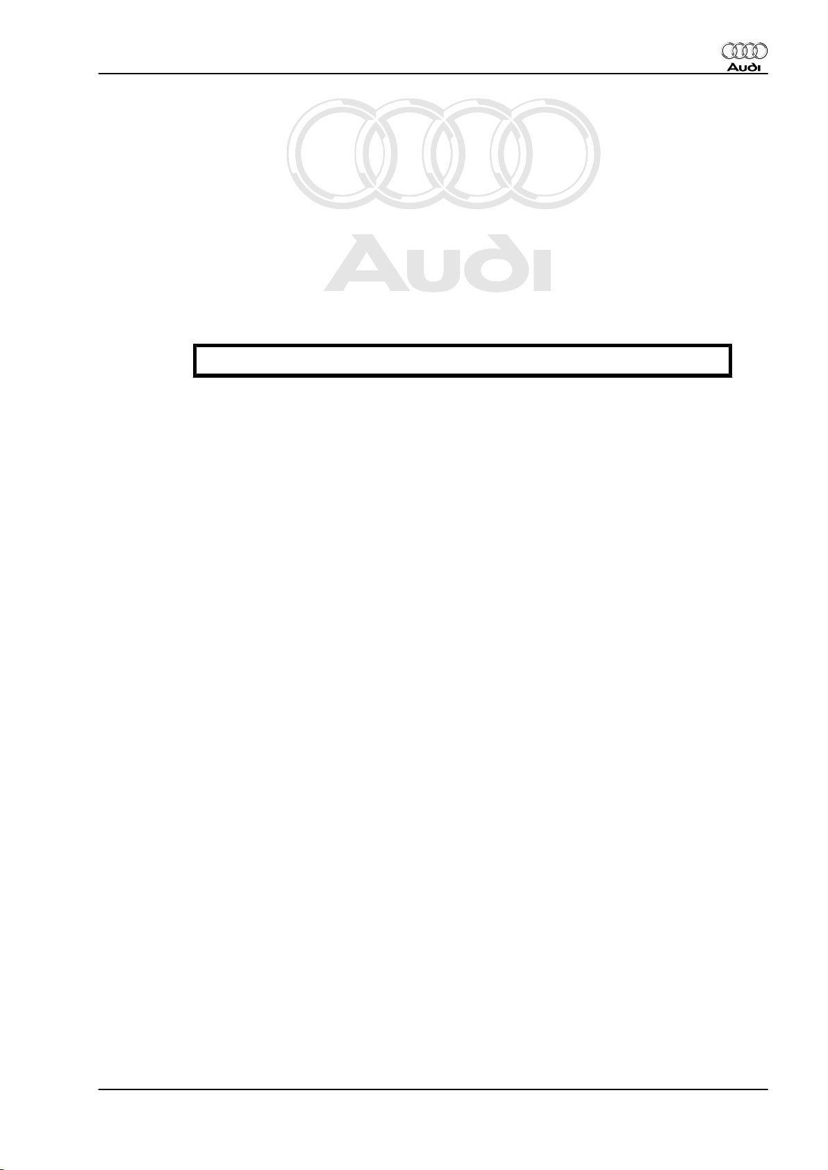
1.2.1 Radio systems “chorus” and “concert”
1 - Rear window aerial with amplifier
2 - Radio
3 - Front bass loudspeaker in lower door trim
4 - Front treble loudspeaker in upper door trim
5 - Rear left amplifier with loudspeaker in side trim
6 - Rear right loudspeaker in side trim
7 - CD changer (optional) at rear left of luggage compartment be‐
hind side trim
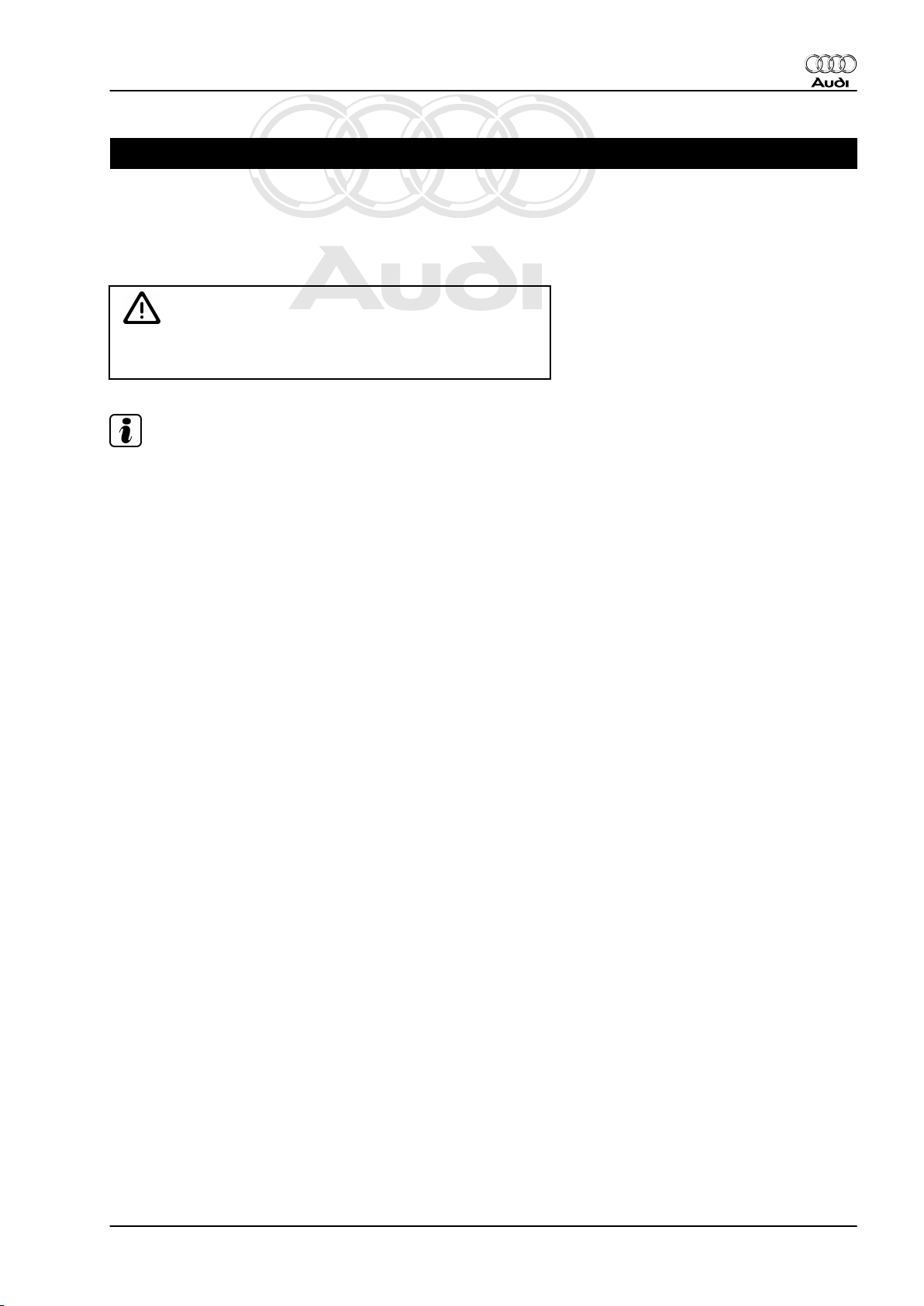
1.2.2 Radio systems “chorus” and “concert”
with BOSE sound system
1 - Rear window aerial with amplifier
2 - Radio
3 - BOSE amplifier at rear right behind side trim
4 - Front bass loudspeaker in lower door trim
5 - Front treble loudspeaker in upper door trim
6 - Rear bass loudspeaker in side trim
7 - Loudspeaker at centre front of dash panel
8 - BOSE microphone (interior microphone) in dash panel insert
(as of MY 03)
9 - CD changer (optional) at rear left of luggage compartment be‐
hind side trim
1.3 Layout of radio systems - Roadster
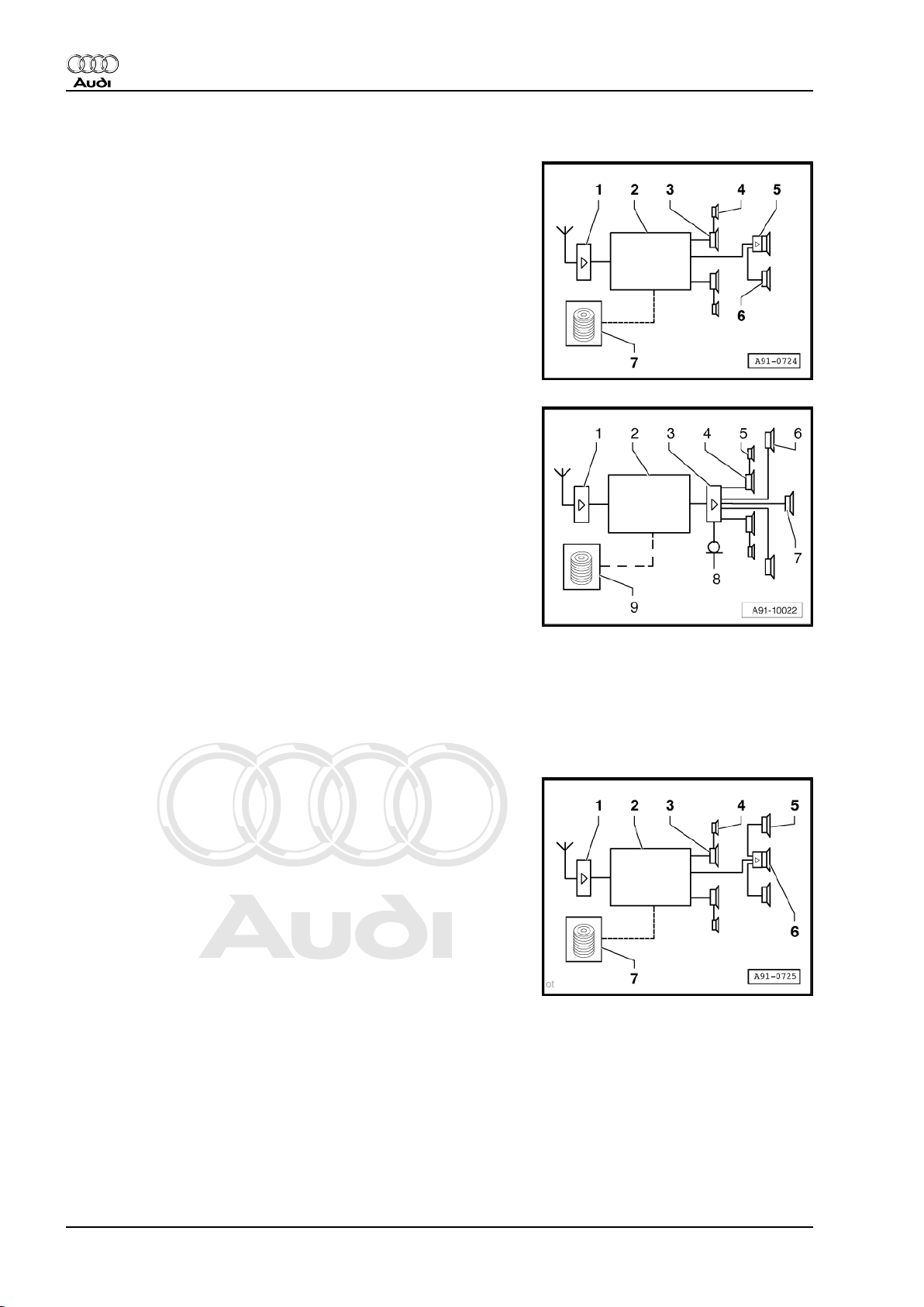
1.3.1 Radio systems “chorus” and “concert”
1 - Rod aerial with aerial amplifier
2 - Radio
3 - Front bass loudspeaker in lower door trim
4 - Front treble loudspeaker in upper door trim
5 - Rear loudspeaker in the side back panel trim
6 - Amplifier with loudspeaker behind centre back panel trim
7 - CD changer (optional) behind the driver's seat in the back
panel trim
2 Rep. Gr.91 - Radio, telephone, navigation
Page 7
Protected by copyright. Copying for private or commercial purposes, in part or in whole, is not
permitted unless authorised by AUDI AG. AUDI AG does not guarantee or accept any liability
with respect to the correctness of information in this document. Copyright by AUDI AG.
Radio, Telephone, Navigation - Edition 10.2003
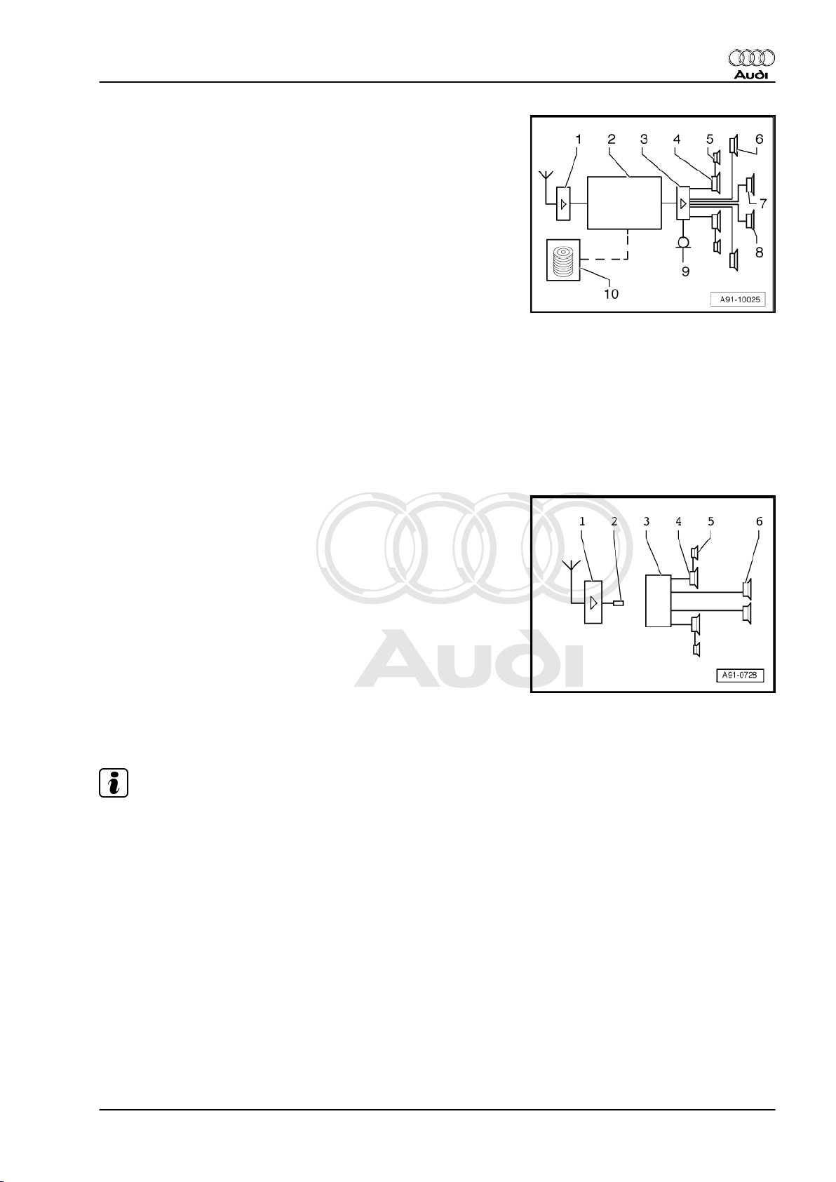
1.3.2 Radio systems “chorus” and “concert”
with BOSE sound system
1 - Rod aerial with aerial amplifier
2 - Radio
3 - BOSE amplifier behind storage box in luggage compartment
4 - Front bass loudspeaker in lower door trim
5 - Front treble loudspeaker in upper door trim
6 - Treble/bass loudspeaker in the side back panel trim
7 - loudspeaker at centre front of dash panel
8 - Rear centre loudspeaker, behind centre back panel trim
9 - BOSE microphone (interior microphone) in ashtray module,
next to ashtray light (as of MY 03)
10 - CD changer (optional) behind the driver's seat in the back
panel trim
1.4 Pre-fitted components for radio installa‐
tion
Audi TT 1999 ➤
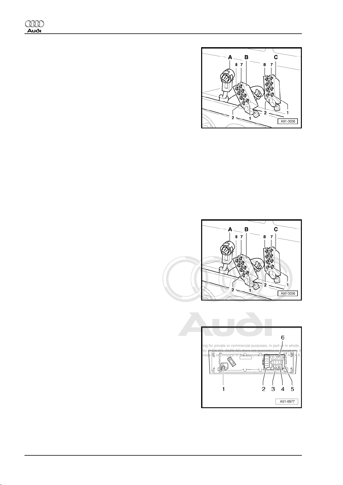
1.4.1 Exploded view
1 - Rear window aerial with amplifier
2 - Aerial cable
3 - Connector II (8-pin) and connector III (8-pin)
3 - Front bass loudspeaker in lower door trim
5 - Front treble loudspeaker in upper door trim
6 - Rear treble/bass loudspeaker in side trim
1.4.2 Contact assignment of multi-pin connec‐
tors
Note!
Contacts which are not listed are unassigned.
1. Radio systems 3
Page 8
Protected by copyright. Copying for private or commercial purposes, in part or in whole, is not
permitted unless authorised by AUDI AG. AUDI AG does not guarantee or accept any liability
with respect to the correctness of information in this document. Copyright by AUDI AG.
Audi TT 1999 ➤
Radio, Telephone, Navigation - Edition 10.2003
Multi-pin connector II, 8-pin, brown (-C-)
1 - Rear right loudspeaker (+)
2 - Rear right loudspeaker (-)
3 - Front right loudspeaker (+)
4 - Front right loudspeaker (-)
5 - Front left loudspeaker (+)
6 - Front left loudspeaker (-)
7 - Rear left loudspeaker (+)
8 - Rear left loudspeaker (-)
Multi-pin connector III, 8-pin, black (-B-)
6 - Switch illumination (terminal 58s)
7 - Battery + (terminal 30)
8 - Earth (terminal 31)
Connection A: aerial wiring
1.4.3 Connecting radio with pre-fitted compo‐
nents for radio installation
– Carefully lever off cover from centre console and remove.
– Connect aerial wire -A-.
– Connect black connector -B- and brown connector -C- to radio.
– Carefully insert radio in dash panel and engage in mounting
frame.
– Activate anti-theft coding if applicable (see Radio Operating
Instructions).
1.5 Connectors on back of “chorus” and “concert” radio
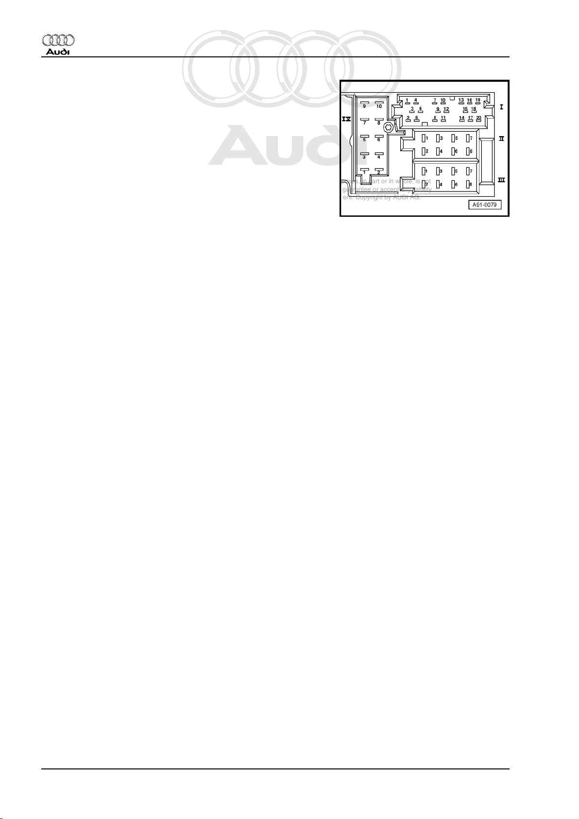
1.5.1 “chorus” radio
1 - Aerial connection
2 - Multi-pin connector IV, 10-pin, red
3 - Multi-pin connector III, 8-pin, black
4 - Multi-pin connector II, 8-pin, brown
5 - Fuse for unit
6 - Multi-pin connector I, 20-pin
4 Rep. Gr.91 - Radio, telephone, navigation
Page 9
Protected by copyright. Copying for private or commercial purposes, in part or in whole, is not
permitted unless authorised by AUDI AG. AUDI AG does not guarantee or accept any liability
with respect to the correctness of information in this document. Copyright by AUDI AG.
Radio, Telephone, Navigation - Edition 10.2003
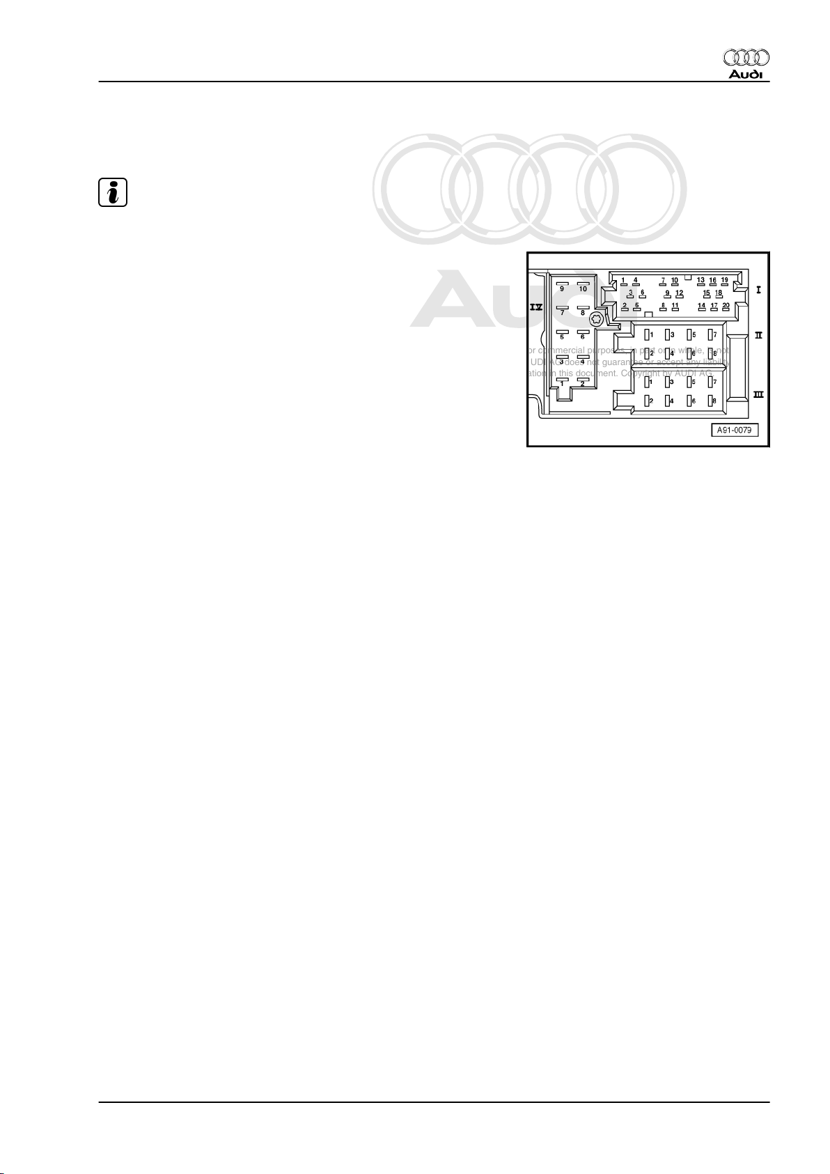
1.5.2 Contact assignment of multi-pin connec‐
tors
Note!
Contacts which are not listed are unassigned.
Multi-pin connector I, 20-pin
1 - Rear left signal
2 - Rear right signal
3 - Signal earth
6 - Switched positive (amplifier)
7 - CAN bus High (infotainment) (as of MY 02)
10 - Earth (CD changer) (as of MY 02)
12 - CAN bus Low (infotainment) (as of MY 02)
13 - CD data in (CD changer)
14 - CD data out (CD changer)
15 - CD-CLK in (CD changer)
16 - Power supply + (CD changer)
17 - Switched positive (CD changer)
18 - Signal earth (CD changer)
19 - Left signal (CD changer)
20 - Right signal (CD changer)
Multi-pin connector II, 8-pin, brown
3 - Front right loudspeaker (+)
4 - Front right loudspeaker (-)
Audi TT 1999 ➤
5 - Front left loudspeaker (+)
6 - Front left loudspeaker (-)
1. Radio systems 5
Page 10
Protected by copyright. Copying for private or commercial purposes, in part or in whole, is not
permitted unless authorised by AUDI AG. AUDI AG does not guarantee or accept any liability
with respect to the correctness of information in this document. Copyright by AUDI AG.
Audi TT 1999 ➤
Radio, Telephone, Navigation - Edition 10.2003
Multi-pin connector III, 8-pin, black
1 - GALA (vehicle speed signal) (up to MY 01)
2 - Telephone muting (up to MY 01)
- Anti-theft alarm earth (as of MY 02)
3 - K diagnosis
4 - Terminal 86s (S-contact) (up to MY 01)
5 - Switched positive for aerial amplifier (up to MY 01)
6 - Switch illumination (terminal 58s) (up to MY 01)
7 - Battery + (terminal 30)
8 - Earth (terminal 31)
Multi-pin connector IV, 10-pin, red
1 - AF mute (from telephone) (up to MY 03)
2 - Terminal 15 (navigation system only) (up to MY 02)
3 - Telephone (AF +) (not in vehicles equipped with navigation
system)
4 - Telephone (AF -) (not in vehicles equipped with navigation
system)
5 - Navigation (AF+) (navigation system only)
6 - Navigation (AF-) (navigation system only)
7 - Navigation (control wire) (navigation system only)
9 - Display illumination (terminal 58d) (up to MY 01)
10 - Earth (CD changer) (up to MY 01)
6 Rep. Gr.91 - Radio, telephone, navigation
Page 11
Protected by copyright. Copying for private or commercial purposes, in part or in whole, is not
permitted unless authorised by AUDI AG. AUDI AG does not guarantee or accept any liability
with respect to the correctness of information in this document. Copyright by AUDI AG.
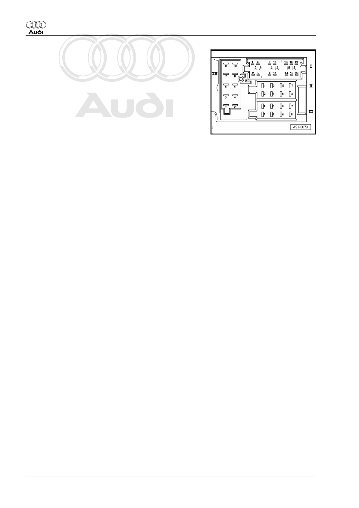
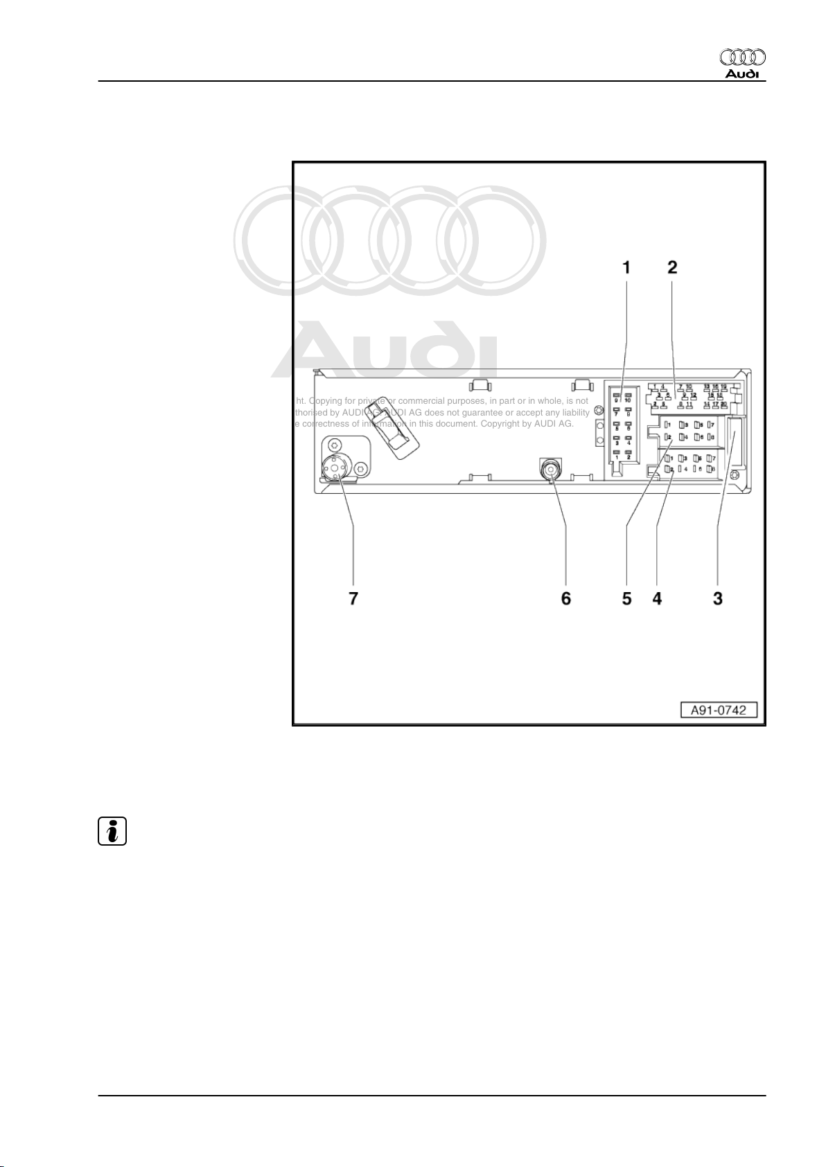
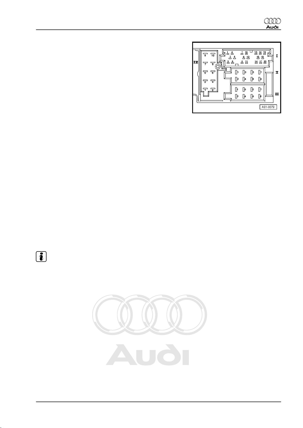
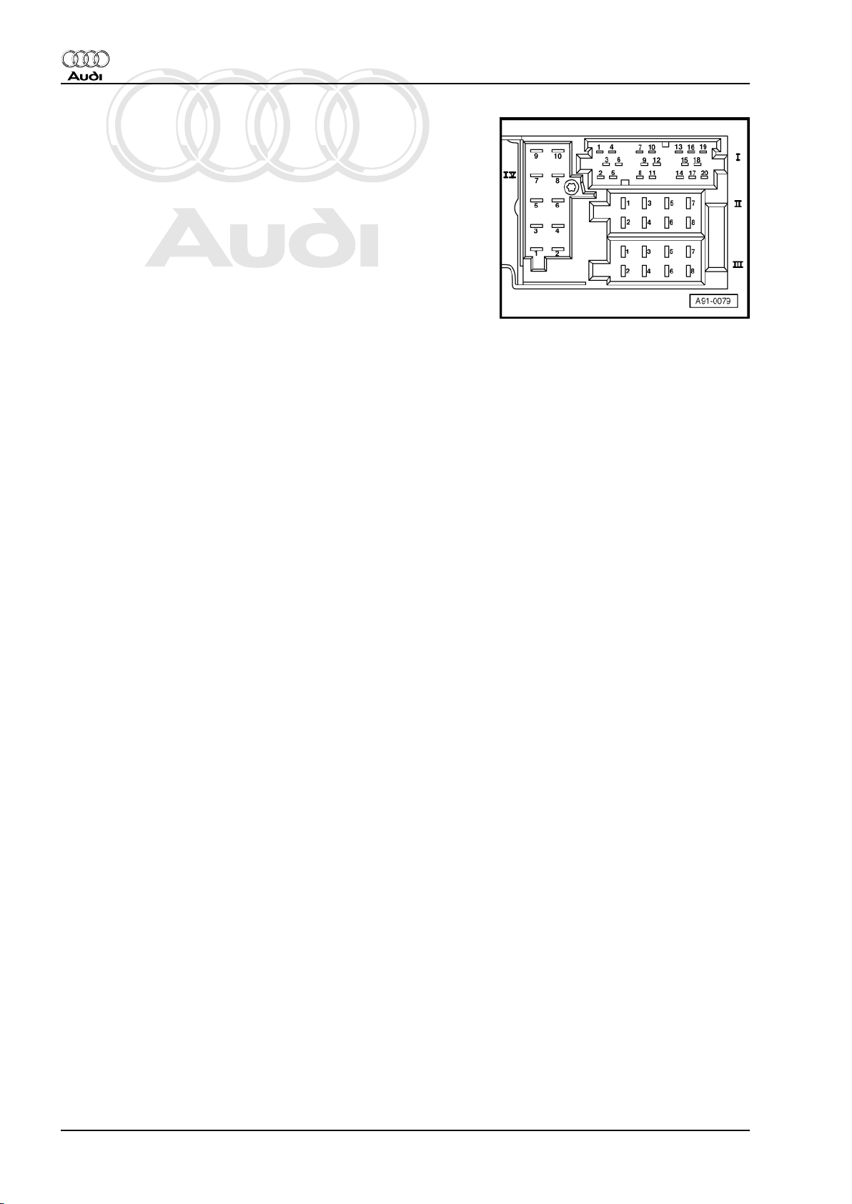
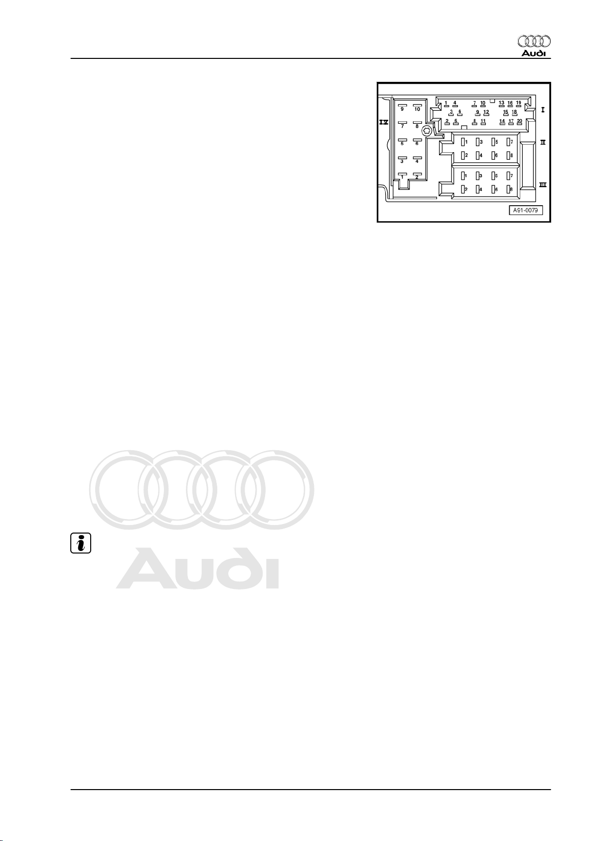
1.5.3 “concert” radio
1 - Multi-pin connector IV, 10pin, red
2 - Multi-pin connector I, 20-pin
3 - Fuse for unit
4 - Multi-pin connector III, 8pin, black
5 - Multi-pin connector II, 8-pin,
brown
6 - Aerial connection (IF) (as of
MY 02) not used
7 - Aerial connection (HF) from
aerial amplifier
Audi TT 1999 ➤
Radio, Telephone, Navigation - Edition 10.2003
1.5.4 Contact assignment of multi-pin connec‐
tors
Note!
Contacts which are not listed are unassigned.
1. Radio systems 7
Page 12
Protected by copyright. Copying for private or commercial purposes, in part or in whole, is not
permitted unless authorised by AUDI AG. AUDI AG does not guarantee or accept any liability
with respect to the correctness of information in this document. Copyright by AUDI AG.
Audi TT 1999 ➤
Radio, Telephone, Navigation - Edition 10.2003
Multi-pin connector I, 20-pin
1 - Rear left signal
2 - Rear right signal
3 - Signal earth
4 - Front left signal (up to MY 01)
5 - Front right signal (up to MY 01)
6 - Switched positive (amplifier)
7 - CAN bus High (infotainment) (as of MY 02)
8 - Clock signal (up to MY 01)
9 - Data signal (up to MY 01)
10 - Enable signal (up to MY 01)
- Earth (CD changer) (as of MY 02)
11 - Remote control/steering wheel (up to MY 01)
12 - CAN bus Low (infotainment) (as of MY 02)
13 - CD data in (CD changer)
14 - CD data out (CD changer)
15 - CD-CLK (CD changer)
16 - Power supply + (CD changer)
17 - Switched positive (CD changer)
18 - Signal earth (CD changer)
19 - Left signal (CD changer)
20 - Right signal (CD changer)
Multi-pin connector II, 8-pin, brown
3 - Front right loudspeaker (+)
4 - Front right loudspeaker (-)
5 - Front left loudspeaker (+)
6 - Front left loudspeaker (-)
8 Rep. Gr.91 - Radio, telephone, navigation
Page 13
Protected by copyright. Copying for private or commercial purposes, in part or in whole, is not
permitted unless authorised by AUDI AG. AUDI AG does not guarantee or accept any liability
with respect to the correctness of information in this document. Copyright by AUDI AG.
Radio, Telephone, Navigation - Edition 10.2003
Multi-pin connector III, 8-pin, black
1 - GALA (vehicle speed signal) (up to MY 01)
2 - Telephone muting (up to MY 01)
- Anti-theft alarm earth (as of MY 02)
3 - K diagnosis
4 - Terminal 86s (S-contact) (up to MY 01)
5 - Switched positive for aerial amplifier (up to MY 01)
6 - Switch illumination (terminal 58s) (up to MY 01)
7 - Battery + (terminal 30)
8 - Earth (terminal 31)
Multi-pin connector IV, 10-pin, red
1 - AF mute (from telephone) (up to MY 03)
2 - Terminal 15 (navigation system only) (up to MY 02)
3 - Telephone (AF+) (not in vehicles equipped with navigation
system)
4 - Telephone (AF-) (not in vehicles equipped with navigation
system)
5 - Navigation (AF+) (navigation system only)
6 - Navigation (AF-) (navigation system only)
7 - Navigation (control wire) (navigation system only)
9 - Display illumination (terminal 58d) (up to MY 01)
10 - Earth (CD changer) (up to MY 01)
Audi TT 1999 ➤
1.5.5 Contact assignment of multi-pin connec‐
tors for BOSE sound system
Note!
Contacts which are not listed are unassigned.
1. Radio systems 9
Page 14
Protected by copyright. Copying for private or commercial purposes, in part or in whole, is not
permitted unless authorised by AUDI AG. AUDI AG does not guarantee or accept any liability
with respect to the correctness of information in this document. Copyright by AUDI AG.
Audi TT 1999 ➤
Radio, Telephone, Navigation - Edition 10.2003
Multi-pin connector I, 20-pin
1 - Rear left signal (as of MY 04 Roadster only)
2 - Rear right signal (as of MY 04 Roadster only)
3 - Signal earth
4 - Front left signal
5 - Front right signal
6 - Switched positive (BOSE amplifier)
7 - CAN bus High (infotainment) (as of MY 02)
8 - Clock signal (up to MY 01)
9 - Data signal (up to MY 01)
10 - Enable signal (up to MY 01)
- Earth (CD changer) (as of MY 02)
11 - Remote control/steering wheel (up to MY 01)
12 - CAN bus Low (infotainment) (as of MY 02)
13 - CD data in (CD changer)
14 - CD data out (CD changer)
15 - CD-CLK (CD changer)
16 - Power supply + (CD changer)
17 - Switched positive (CD changer)
18 - Signal earth (CD changer)
19 - Left signal (CD changer)
20 - Right signal (CD changer)
Multi-pin connector II, 8-pin, brown
3 - Front right loudspeaker (+) (up to MY 01)
4 - Front right loudspeaker (-) (up to MY 01)
5 - Front left loudspeaker (+) (up to MY 01)
6 - Front left loudspeaker (-) (up to MY 01)
10 Rep. Gr.91 - Radio, telephone, navigation
Page 15
Protected by copyright. Copying for private or commercial purposes, in part or in whole, is not
permitted unless authorised by AUDI AG. AUDI AG does not guarantee or accept any liability
with respect to the correctness of information in this document. Copyright by AUDI AG.
Radio, Telephone, Navigation - Edition 10.2003
Multi-pin connector III, 8-pin, black
1 - GALA (vehicle speed signal) (up to MY 01)
- BOSE code (as of MY 02)
2 - Telephone muting (up to MY 01)
- Anti-theft alarm earth (as of MY 02)
3 - K diagnosis
4 - Terminal 86s (S-contact) (up to MY 01)
5 - Switched positive for aerial amplifier (up to MY 01)
6 - Switch illumination (terminal 58s) (up to MY 01)
7 - Battery + (terminal 30)
8 - Earth (terminal 31)
Multi-pin connector IV, 10-pin, red
1 - Telephone muting (up to MY 03)
2 - Terminal 15 (navigation system only) (up to MY 01)
3 - Telephone (AF +) (not in vehicles equipped with navigation
system)
4 - Telephone (AF -) (not in vehicles equipped with navigation
system)
5 - Navigation (AF+) (navigation system only)
6 - Navigation (AF-) (navigation system only)
7 - Navigation (control wire) (navigation system only)
9 - Display illumination (terminal 58d) (up to MY 01)
10 - Earth (CD changer) (up to MY 01)
Audi TT 1999 ➤
1.6 Connector on BOSE amplifier
1.6.1 BOSE amplifier up to MY 02
Note!
Contacts which are not listed are unassigned.
1. Radio systems 11
Page 16
Protected by copyright. Copying for private or commercial purposes, in part or in whole, is not
permitted unless authorised by AUDI AG. AUDI AG does not guarantee or accept any liability
with respect to the correctness of information in this document. Copyright by AUDI AG.
Audi TT 1999 ➤
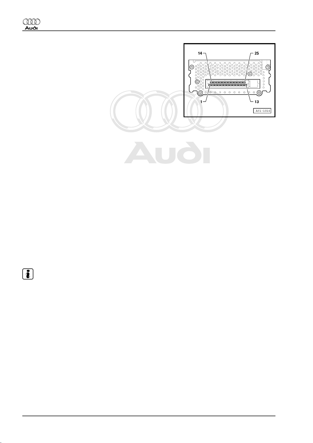
Radio, Telephone, Navigation - Edition 10.2003
Multi-pin connector, 25-pin
1 - AF + (from telephone/navigation)
2 - AF - (from telephone/navigation)
6 - Signal earth (from radio)
7 - Rear right signal (from radio)
8 - Rear left signal (from radio)
9 - Front right signal (from radio)
10 - Front left signal (from radio)
11 - Earth (terminal 31)
12 - AF mute (from telephone)
13 - Battery + (terminal 30)
14 - Subwoofer (+)
15 - Subwoofer (-)
16 - Front left loudspeaker (-)
17 - Front left loudspeaker (+)
18 - Front right loudspeaker (+)
19 - Front right loudspeaker (-)
20 - Rear left loudspeaker (+)
21 - Rear right loudspeaker (-)
22 - Front centre loudspeaker (+)
23 - Front centre loudspeaker (-)
24 - Terminal 15
25 - Positive switched (from radio)
1.6.2 Coupe as of MY 03
Note!
Contacts which are not listed are unassigned.
12 Rep. Gr.91 - Radio, telephone, navigation
Page 17
Protected by copyright. Copying for private or commercial purposes, in part or in whole, is not
permitted unless authorised by AUDI AG. AUDI AG does not guarantee or accept any liability
with respect to the correctness of information in this document. Copyright by AUDI AG.
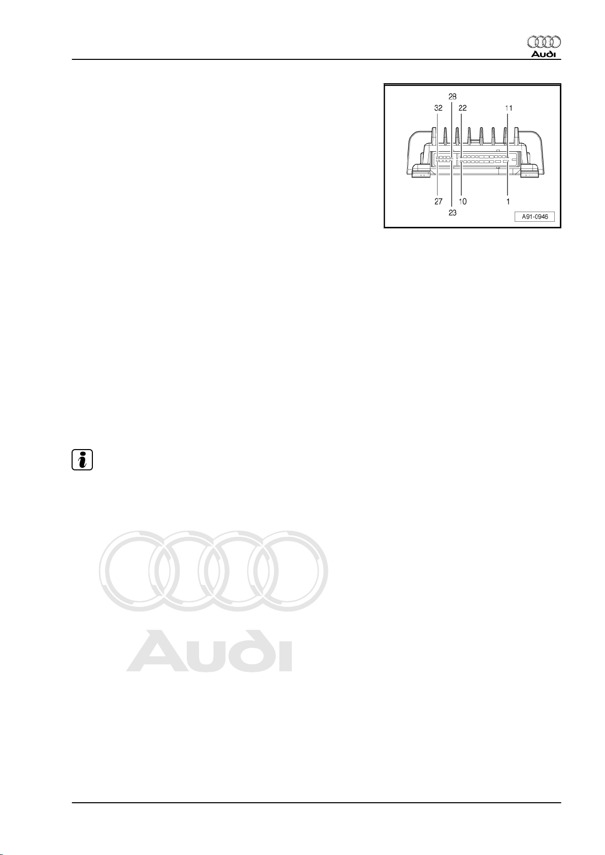
Multi-pin connector, 32-pin
1 - Battery + (terminal 30)
2 - Earth (terminal 31)
3 - Rear right loudspeaker (+)
5 - Front centre loudspeaker (+)
6 - Positive switched (from radio)
7 - Signal earth (from radio)
11 - Rear left loudspeaker (+)
12 - Rear left loudspeaker (-)
15 - Rear right loudspeaker (-)
17 - Front centre loudspeaker (-)
19 - Front left signal (from radio)
20 - Front right signal (from radio)
26 - Front right loudspeaker (-)
27 - Front right loudspeaker (+)
29 - Microphone (+) (interior microphone)
30 - Microphone (-) (interior microphone)
31 - Front left loudspeaker (+)
32 - Front left loudspeaker (-)
Audi TT 1999 ➤
Radio, Telephone, Navigation - Edition 10.2003
1.6.3 Roadster as of MY 03
Note!
Contacts which are not listed are unassigned.
1. Radio systems 13
Page 18

Protected by copyright. Copying for private or commercial purposes, in part or in whole, is not
permitted unless authorised by AUDI AG. AUDI AG does not guarantee or accept any liability
with respect to the correctness of information in this document. Copyright by AUDI AG.
Audi TT 1999 ➤
Radio, Telephone, Navigation - Edition 10.2003
Multi-pin connector, 32-pin
1 - Battery + (terminal 30)
2 - Earth (terminal 31)
3 - Subwoofer (+)
4 - Rear loudspeaker (-)
5 - Front centre loudspeaker (+)
6 - Positive switched (from radio)
7 - Signal earth (from radio)
15 - Subwoofer (-)
16 - Rear loudspeaker (+)
17 - Front centre loudspeaker (-)
18 - Convertible top open/closed (from CL control unit)
19 - Front left signal (from radio)
20 - Front right signal (from radio)
21 - Rear left signal (from radio)
22 - Rear right signal (from radio)
26 - Front right loudspeaker (-)
27 - Front right loudspeaker (+)
29 - Microphone (+) (interior microphone)
30 - Microphone (-) (interior microphone)
31 - Front left loudspeaker (+)
32 - Front left loudspeaker (-)
14 Rep. Gr.91 - Radio, telephone, navigation
Page 19

Protected by copyright. Copying for private or commercial purposes, in part or in whole, is not
permitted unless authorised by AUDI AG. AUDI AG does not guarantee or accept any liability
with respect to the correctness of information in this document. Copyright by AUDI AG.
Radio, Telephone, Navigation - Edition 10.2003
1.7 Exploded view of radio systems - Coupe
1.7.1 Standard
1 - Radio -R-
❑ In upper section of cen‐
tre console
❑ Removing and installing
⇒ page 19
2 - Front left -R21- / front right
-R23- bass loudspeaker
❑ In lower front left/right
door trim
❑ Removing and installing
⇒ page 19
3 - Front left -R20- / front right
-R22- treble loudspeaker
❑ In upper front left/right
door trim
❑ Removing and installing
⇒ page 20
4 - Amplifier with subwoofer
(on left in luggage compart‐
ment) -R44-
❑ Contains rear left treble
loudspeaker -R14- and
rear left bass loud‐
speaker -R15❑ In rear left side trim
❑ Removing and installing
⇒ page 22
5 - Aerial amplifier
❑ Behind tailgate trim at
left
❑ Removing and installing
⇒ page 27
6 - CD changer -R41-
❑ Behind rear left side trim
❑ Removing and installing ⇒ page 22
❑ Checking wiring connection ⇒ page 24
7 - Rear right loudspeaker -R5-
❑ Contains rear right treble loudspeaker -R16- and rear right bass loudspeaker -R17❑ In rear right side trim
❑ Removing and installing ⇒ page 21
Audi TT 1999 ➤
1. Radio systems 15
Page 20

Protected by copyright. Copying for private or commercial purposes, in part or in whole, is not
permitted unless authorised by AUDI AG. AUDI AG does not guarantee or accept any liability
with respect to the correctness of information in this document. Copyright by AUDI AG.
Audi TT 1999 ➤
Radio, Telephone, Navigation - Edition 10.2003
1.7.2 BOSE sound system
1 - Radio -R-
❑ In upper section of cen‐
tre console
❑ Removing and installing
⇒ page 19
2 - Front left -R21- / front right
-R23- bass loudspeaker
❑ In lower front left/right
door trim
❑ Removing and installing
⇒ page 19
3 - Front left -R20- / front right
-R22- treble loudspeaker
❑ In upper front left/right
door trim
❑ Removing and installing
⇒ page 20
4 - Rear right treble loudspeak‐
er -R16- and rear right bass
loudspeaker -R17-
❑ In rear left and right side
trim
❑ Removing and installing
⇒ page 21
5 - Aerial amplifier
❑ Behind tailgate trim at
left
❑ Removing and installing
⇒ page 27
6 - CD changer -R41-
❑ Behind rear left side trim
❑ Removing and installing
⇒ page 22
❑ Checking wiring connection ⇒ page 24
7 - Amplifier -R12-
❑ Behind rear right side trim
❑ Removing and installing ⇒ page 25
8 - Interior microphone -R74-
❑ As of MY 03
❑ In dash panel insert
❑ Removing and installing
9 - Front centre loudspeaker -R70-
❑ In front centre of dash panel (in left defroster nozzle)
❑ Removing and installing ⇒ page 20
16 Rep. Gr.91 - Radio, telephone, navigation
Page 21

Protected by copyright. Copying for private or commercial purposes, in part or in whole, is not
permitted unless authorised by AUDI AG. AUDI AG does not guarantee or accept any liability
with respect to the correctness of information in this document. Copyright by AUDI AG.
Radio, Telephone, Navigation - Edition 10.2003
1.8 Exploded view of radio systems - Road‐
ster
1.8.1 Standard
1 - Radio -R-
❑ In upper section of cen‐
tre console
❑ Removing and installing
⇒ page 19
2 - Front left -R21- / front right
-R23- bass loudspeaker
❑ In lower front left/right
door trim
❑ Removing and installing
⇒ page 19
3 - Front left -R20- / front right
-R22- treble loudspeaker
❑ In upper front left/right
door trim
❑ Removing and installing
⇒ page 20
4 - CD changer -R41-
❑ Behind driver's seat in
back panel trim
❑ Removing and installing
⇒ page 23
❑ Checking wiring con‐
nection ⇒ page 24
5 - Rear left -R4- / rear right R5- loudspeaker
❑ In left/right back panel
side trim
❑ Removing and installing
⇒ page 21
6 - Aerial
❑ Radio or radio/tele‐
phone rod aerial with
amplifier
❑ Removing and installing (up to MY 00) ⇒ page 28
❑ Removing and installing (as of MY 01) ⇒ page 42
7 - Amplifier with subwoofer (on left in luggage compartment) -R44-
❑ Behind centre rear panel trim
❑ Removing and installing ⇒ page 22
Audi TT 1999 ➤
1. Radio systems 17
Page 22

Protected by copyright. Copying for private or commercial purposes, in part or in whole, is not
permitted unless authorised by AUDI AG. AUDI AG does not guarantee or accept any liability
with respect to the correctness of information in this document. Copyright by AUDI AG.
Audi TT 1999 ➤
Radio, Telephone, Navigation - Edition 10.2003
1.8.2 BOSE sound system
1 - Radio -R-
❑ In upper section of cen‐
tre console
❑ Removing and installing
⇒ page 19
2 - Front centre loudspeaker R70-
❑ In front centre of dash
panel (in left defroster
nozzle)
❑ Removing and installing
⇒ page 20
3 - Front left -R21- / front right
-R23- bass loudspeaker
❑ In lower front left/right
door trim
❑ Removing and installing
⇒ page 19
4 - Front left -R20- / front right
-R22- treble loudspeaker
❑ In upper front left/right
door trim
❑ Removing and installing
⇒ page 20
5 - CD changer -R41-
❑ Behind driver's seat in
back panel trim
❑ Removing and installing
⇒ page 23
❑ Checking wiring con‐
nection ⇒ page 24
6 - Rear left bass loudspeaker
-R15- / rear right treble loud‐
speaker -R16-
❑ In left/right back panel side trim
❑ Removing and installing ⇒ page 21
7 - Aerial
❑ Radio or radio/telephone rod aerial with amplifier
❑ Removing and installing (up to MY 00) ⇒ page 28
❑ Removing and installing (as of MY 01) ⇒ page 42
8 - Interior loudspeaker 2 -R71-
❑ Behind centre rear panel trim
❑ Removing and installing ⇒ page 22
9 - Amplifier -R12-
❑ Behind storage box in luggage compartment
❑ Removing and installing ⇒ page 25
10 - Interior microphone -R74-
❑ As of MY 03
❑ In ashtray module next to ashtray light
❑ Removing and installing
18 Rep. Gr.91 - Radio, telephone, navigation
Page 23

Protected by copyright. Copying for private or commercial purposes, in part or in whole, is not
permitted unless authorised by AUDI AG. AUDI AG does not guarantee or accept any liability
with respect to the correctness of information in this document. Copyright by AUDI AG.
Radio, Telephone, Navigation - Edition 10.2003
1.9 Removing and installing radio
Special tools and workshop equipment required
♦ Radio release keys -3344-
– Switch off all electrical consumers.
– Remove ignition key.
Removing:
– Request anti-theft encoding from customer.
– Insert radio release keys -3344- in release slots as shown
-arrows- until they engage. Pointed ends of grips must face
outwards.
– Grasp hold of grips on radio release keys -3344- and pull radio
out of dash panel.
– Release and unplug connectors at radio.
– Press tabs on radio and pull out release tools.
Installing:
– Plug in all connectors.
– Carefully slide radio into dash panel and engage it in mounting
frame.
– Activate anti-theft encoding.
If the radio has been exchanged:
– Encode and adapt radio: ⇒ Radio, Telephone and Navigation
System Self-diagnosis; Rep. Gr. 01 .
Audi TT 1999 ➤
1.10 Removing and installing speakers
1.10.1 Removing and installing mid-range/ bass loudspeaker
– Switch off all electrical consumers.
– Remove ignition key.
Removing:
– Remove door trim ⇒ General Body Repairs, Interior; Rep. Gr.
70 .
1. Radio systems 19
Page 24

Protected by copyright. Copying for private or commercial purposes, in part or in whole, is not
permitted unless authorised by AUDI AG. AUDI AG does not guarantee or accept any liability
with respect to the correctness of information in this document. Copyright by AUDI AG.
Audi TT 1999 ➤
Radio, Telephone, Navigation - Edition 10.2003
– Carefully detach insulating mat on rear of door trim around
bass/mid-range loudspeaker from trim.
– Unplug connectors -1- from loudspeaker -2-.
– Remove the bolts -arrows- at loudspeaker -2- and then detach
the loudspeaker from the trim.
Installing:
– Installation is performed in reverse sequence.
1.10.2 Removing and installing treble loud‐
speaker
– Switch off all electrical consumers.
– Remove ignition key.
Removing:
– Remove door trim ⇒ General Body Repairs, Interior; Rep. Gr.
70 .
– Carefully detach insulating mat from back of door trim.
– Work back from treble loudspeaker -3- along soldered con‐
necting cables -1- of loudspeaker as far as connector console
-2- (grey) and then unplug connector for treble loudspeaker
-3-.
– Press clips -arrows- away from treble loudspeaker and then
detach loudspeaker from trim.
Installing:
– Installation is performed in reverse sequence.
1.10.3 Removing and installing front centre loudspeaker
– Switch off all electrical consumers.
– Remove ignition key.
20 Rep. Gr.91 - Radio, telephone, navigation
Page 25

Protected by copyright. Copying for private or commercial purposes, in part or in whole, is not
permitted unless authorised by AUDI AG. AUDI AG does not guarantee or accept any liability
with respect to the correctness of information in this document. Copyright by AUDI AG.
Radio, Telephone, Navigation - Edition 10.2003
Removing:
– Carefully detach left cover -1- of defroster vent in dash panel.
– Slacken off bolts -2- at centre loudspeaker -3-.
– Take loudspeaker out of insert and unplug connector -4-.
Installing:
– Installation is performed in reverse sequence.
Audi TT 1999 ➤
1.10.4 Removing and installing loudspeaker in rear side trim - Coupe
– Switch off all electrical consumers.
– Remove ignition key.
Removing:
– Remove rear side trim ⇒ General Body Repairs, Interior; Rep.
Gr. 70 .
– Screw out bolts -arrows- (2 Nm) at loudspeaker -1-.
– Unplug connector -2- and then take loudspeaker out of insert.
Installing:
– Installation is performed in reverse sequence.
1.10.5 Removing and installing loudspeaker in back panel side trim - Roadster
– Switch off all electrical consumers.
– Remove ignition key.
Removing:
– Remove back panel side trim ⇒ General Body Repairs, Inte‐
rior; Rep. Gr. 70 .
1. Radio systems 21
Page 26

Protected by copyright. Copying for private or commercial purposes, in part or in whole, is not
permitted unless authorised by AUDI AG. AUDI AG does not guarantee or accept any liability
with respect to the correctness of information in this document. Copyright by AUDI AG.
Audi TT 1999 ➤
Radio, Telephone, Navigation - Edition 10.2003
– Screw out bolts -2- (2.5 Nm) at loudspeaker -1-.
– Unplug connector -5- and detach loudspeaker -1- from bracket
-3-.
– Bracket -3- is attached to back panel by means of three bolts
-4- (2 Nm).
Installing:
– Loudspeaker -1- must be installed such that connector -5- is
positioned as shown.
– Installation is performed in reverse sequence.
1.10.6 Removing and installing loudspeaker
behind back panel centre trim - Road‐
ster
– Switch off all electrical consumers.
– Remove ignition key.
Removing:
– Remove back panel centre trim: ⇒ General Body Repairs, In‐
terior; Rep. Gr. 70 .
– Remove bolts -2- (2.5 Nm).
– Pull out loudspeaker -1- and unplug connector -5-.
Installing:
– On installation, insert lug -3- in mount -4-.
– Installation is performed in reverse sequence.
1.11 Removing and installing CD changer Coupe
The CD changer -1- is located behind the left side trim.
– Switch off all electrical consumers.
– Remove ignition key.
Removing:
– Remove left side trim ⇒ General Body Repairs, Interior; Rep.
Gr. 70 .
– Unplug connector from CD changer.
22 Rep. Gr.91 - Radio, telephone, navigation
Page 27

Protected by copyright. Copying for private or commercial purposes, in part or in whole, is not
permitted unless authorised by AUDI AG. AUDI AG does not guarantee or accept any liability
with respect to the correctness of information in this document. Copyright by AUDI AG.
Radio, Telephone, Navigation - Edition 10.2003
– Screw out bolts -2- (5 Nm) at mounting frame -3-.
– Then screw out bolts -4- (2 Nm) and remove the CD changer
-1-.
Installing:
– Check CD changer adjustment ⇒ page 24
– Installation is performed in reverse sequence.
– After installation check wiring to radio ⇒ page 24 .
1.12 Removing and installing CD changer Roadster
– Switch off all electrical consumers.
– Remove ignition key.
Removing:
– Remove left storage box: ⇒ General Body Repairs, Interior;
Rep. Gr. 70 .
– Remove clip in left storage compartment.
– Slacken off remaining bolts -2- (2 Nm).
– Unplug connector from CD changer.
– Take CD changer out of left storage box.
Installing:
– Check CD changer adjustment ⇒ page 24
– Installation is performed in reverse sequence.
– After installation check wiring to radio ⇒ page 24 .
Audi TT 1999 ➤
1. Radio systems 23
Page 28

Protected by copyright. Copying for private or commercial purposes, in part or in whole, is not
permitted unless authorised by AUDI AG. AUDI AG does not guarantee or accept any liability
with respect to the correctness of information in this document. Copyright by AUDI AG.
Audi TT 1999 ➤
Radio, Telephone, Navigation - Edition 10.2003
1.13 Checking adjustment and wiring con‐
nection of CD changer
1.13.1 Checking adjustment
An adjusting screw is provided on the side of the CD changer for
setting the angle of inclination. Settings differ for TT Roadster and
TT Coupe and must be checked prior to installation and altered if
necessary.
A - Setting for TT Roadster
B - Setting for TT Coupe
1.13.2 Checking wiring connection between ra‐
dio and CD changer
– Switch off radio.
– Press and hold MODE button on radio, and at the same time
switch on the radio.
– Release MODE button.
1. Wiring connection OK
Indicated on radio display:
“CONNECT”
2. Wiring connection not OK
Indicated on radio display:
“NO CDC”
– Check electrical connector on CD changer.
– Repeat wiring check and use current flow diagram to check
wiring if not OK:⇒ Current flow diagrams, Electrical fault find‐
ing and Fitting locations.
24 Rep. Gr.91 - Radio, telephone, navigation
Page 29

Protected by copyright. Copying for private or commercial purposes, in part or in whole, is not
permitted unless authorised by AUDI AG. AUDI AG does not guarantee or accept any liability
with respect to the correctness of information in this document. Copyright by AUDI AG.
Radio, Telephone, Navigation - Edition 10.2003
1.14 Removing and installing BOSE amplifier
- Coupe
The BOSE amplifier -1- is located behind right side trim.
– Switch off all electrical consumers.
– Remove ignition key.
Removing:
– Remove right side trim: ⇒ General Body Repairs, Interior;
Rep. Gr. 70 .
– Unplug connector -1- from amplifier.
– Unscrew the nuts -2- (5 Nm) of the amplifier.
Audi TT 1999 ➤
– Detach amplifier -3- from bracket -4-.
– Unscrew nuts -5- (5 Nm) to remove bracket -4-.
Installing:
– Installation is performed in reverse sequence.
1.15 Removing and installing BOSE amplifier
- Roadster
– Switch off all electrical consumers.
– Remove ignition key.
Removing:
– Remove luggage compartment floor lining: ⇒ General Body
Repairs, Interior; Rep. Gr. 70 .
– Remove storage box ⇒ General Body Repairs, Interior; Rep.
Gr. 70 .
The amplifier is accessible via the opening in the storage box.
1. Radio systems 25
Page 30

Protected by copyright. Copying for private or commercial purposes, in part or in whole, is not
permitted unless authorised by AUDI AG. AUDI AG does not guarantee or accept any liability
with respect to the correctness of information in this document. Copyright by AUDI AG.
Audi TT 1999 ➤
Radio, Telephone, Navigation - Edition 10.2003
– Unplug connector -2- from amplifier.
– The amplifier is mounted on bracket -4- which is inserted at
recesses -1- at bottom and secured with nuts -3- at top.
– To remove the amplifier, unscrew nuts -3- (5 Nm), swivel down
bracket -4- with amplifier and detach.
– The amplifier -2- can then be detached from bracket -1- by
unfastening nuts -3- (5 Nm).
Installing:
– Installation is performed in reverse sequence.
1.16 Function test of BOSE microphone (in‐
terior microphone)
As of MY 03, a microphone is installed with BOSE Sound radio
units for monitoring interior noise (Audiopilot). This is connected
directly to the BOSE amplifier. When noise increases in the inte‐
rior, the amplifier (Audiopilot) automatically adjusts the volume
according to the specified pattern.
When the radio is switched on, the BOSE amplifier checks the
voltage supply level of the microphone. If the result is OK, there
is no reaction.
If the microphone, however, is not installed, three short tones are
emitted three times.
In the case of a short circuit, three short tones are emitted.
Function test of microphone:
– Switch on the radio and tune into a station.
– Tap lightly on the microphone for a while
♦ Coupe: on the top centre of the dash panel insert.
♦ Roadster: below the ashtray
The volume of the radio station tuned to should increase audibly.
1.17 Removing and installing BOSE micro‐
phone (interior microphone) - Coupe
– Switch off all electrical consumers.
– Remove ignition key.
Removing:
– Remove dash panel insert ⇒ Electrical System; Rep. Gr. 90 .
26 Rep. Gr.91 - Radio, telephone, navigation
Page 31

Protected by copyright. Copying for private or commercial purposes, in part or in whole, is not
permitted unless authorised by AUDI AG. AUDI AG does not guarantee or accept any liability
with respect to the correctness of information in this document. Copyright by AUDI AG.
Radio, Telephone, Navigation - Edition 10.2003
– Use screwdriver -arrow- to carefully lever the microphone -1-
out of mount.
– Unplug connector and remove the microphone.
Installing:
– Installation is performed in reverse sequence.
1.18 Removing and installing BOSE micro‐
phone (interior microphone) - Roadster
– Switch off all electrical consumers.
– Remove ignition key.
Removing:
– Remove ashtray ⇒ General Body Repairs, Interior; Rep. Gr.
68 .
– Push the foam tube -1- aside and unplug the connector -2-.
– Lever out the microphone -3- using a small screwdriver.
Installing:
– Installation is performed in reverse sequence.
Audi TT 1999 ➤
1.19 Removing and installing aerial amplifier
- Coupe
– Switch off all electrical consumers.
– Remove ignition key.
Removing:
– Remove boot lid trim: ⇒ General Body Repairs, Interior; Rep.
Gr. 70 .
– Screw out bolts -2- (2.5 Nm) at loudspeaker -1-.
1. Radio systems 27
Page 32

Protected by copyright. Copying for private or commercial purposes, in part or in whole, is not
permitted unless authorised by AUDI AG. AUDI AG does not guarantee or accept any liability
with respect to the correctness of information in this document. Copyright by AUDI AG.
Audi TT 1999 ➤
Radio, Telephone, Navigation - Edition 10.2003
– Unscrew aerial wire -3- and unplug rear window connector
-4- at aerial amplifier -1-.
Installing:
– Installation is performed in reverse sequence.
1.20 Removing and installing aerial - Road‐
ster (up to MY 00)
– Switch off all electrical consumers.
– Remove ignition key.
Removing:
– Open flap in trim on left side of luggage compartment.
– Unscrew aerial rod -5- and detach cover -3- (cover is clipped
on and is fitted with a locking element -4-).
– Unfasten union nut with seal -2- (4 Nm) and detach aerial base
-1- downwards.
– Detach aerial wires from aerial base -1-.
Installing:
– Installation is performed in reverse sequence.
28 Rep. Gr.91 - Radio, telephone, navigation
Page 33

Protected by copyright. Copying for private or commercial purposes, in part or in whole, is not
permitted unless authorised by AUDI AG. AUDI AG does not guarantee or accept any liability
with respect to the correctness of information in this document. Copyright by AUDI AG.
Radio, Telephone, Navigation - Edition 10.2003
2 Servicing telephone system
2.1 General information
Caution
Disconnect battery earth strap before working on electrical
system.
Note!
♦
Establish radio anti-theft code before disconnecting battery.
♦
On reconnecting battery, remember to activate vehicle equip‐
ment (radio, clock, electric window lifters, engine) in accord‐
ance with owner's manual.
Audi TT 1999 ➤
2.2 Pre-fitted components for mobile phone installation (up to MY 03)
1 - Mobile phone in handset
cradle
❑ On right next to centre
console
2 - Hands-free loudspeaker
❑ Vehicles with no radio
system only
❑ In front centre of dash
panel (in right defroster
nozzle)
3 - Radio -R-
❑ In centre console
4 - Radio loudspeaker
5 - Mobile phone operating
electronics control unit -J412-
Coupe:
❑ Beneath rear seat
bench
Roadster:
❑ Behind subwoofer un‐
der back panel centre
trim
6 - Telephone microphone R38- (hands-free microphone)
Coupe:
❑ Behind interior light /
ATA sensor (up to MY
01)
❑ In dash panel insert (as
of MY 02)
Roadster:
2. Servicing telephone system 29
Page 34

Protected by copyright. Copying for private or commercial purposes, in part or in whole, is not
permitted unless authorised by AUDI AG. AUDI AG does not guarantee or accept any liability
with respect to the correctness of information in this document. Copyright by AUDI AG.
Audi TT 1999 ➤
Radio, Telephone, Navigation - Edition 10.2003
❑ In dash panel insert
7 - Aerial amplifier, mobile telephone (compensor) -R86-
❑ Behind rear left side trim
8 - Telephone aerial -R65-
Coupe:
❑ Roof aerial
Roadster:
❑ Rod aerial in rear of left wing
2.3 Pre-fitted components for mobile phone installation (as of MY 04)
1 - Mount for telephone
❑ On right of dash panel
2 - Radio -R-
❑ In centre console
3 - Radio loudspeaker
4 - Aerial for Bluetooth -R152-
❑ At mobile phone operat‐
ing electronics control
unit
5 - Mobile phone operating
electronics control unit -J412-
Coupe:
❑ Beneath rear seat
bench
Roadster:
❑ Behind subwoofer be‐
neath trim in centre of
back panel
6 - Telephone microphone R38- (hands-free microphone)
Coupe:
❑ Behind interior light /
ATA sensor
Roadster:
❑ In dash panel insert
7 - Aerial amplifier, mobile tel‐
ephone (compensor) -R86-
❑ Behind rear left side trim
8 - Telephone aerial -R65-
Coupe:
❑ Roof aerial
Roadster:
❑ Rod aerial in rear of left wing
30 Rep. Gr.91 - Radio, telephone, navigation
Page 35

Protected by copyright. Copying for private or commercial purposes, in part or in whole, is not
permitted unless authorised by AUDI AG. AUDI AG does not guarantee or accept any liability
with respect to the correctness of information in this document. Copyright by AUDI AG.
Radio, Telephone, Navigation - Edition 10.2003
2.4 Connectors at mobile telephone operat‐
ing electronics control unit -J412-
2.4.1 Mobile telephone operating electronics control unit -J412- up to MY 03
Note!
Contacts which are not listed are unassigned.
Multi-pin connector, 18-pin
1 - Earth (terminal 31)
3 - GALA (road speed signal)
4 - AF mute (to radio)
7 - Hands-free loudspeaker (-) (up to MY 01)
9 - Hands-free microphone (-)
10 - Terminal 15
11 - Battery + (terminal 30)
12 - Switch illumination (terminal 58s)
13 - Mobile phone ON signal (to mobile phone aerial amplifier)
16 - Hands-free loudspeaker (+) (up to MY 01)
18 - Hands-free microphone (+)
Audi TT 1999 ➤
2. Servicing telephone system 31
Page 36

Protected by copyright. Copying for private or commercial purposes, in part or in whole, is not
permitted unless authorised by AUDI AG. AUDI AG does not guarantee or accept any liability
with respect to the correctness of information in this document. Copyright by AUDI AG.
Audi TT 1999 ➤
Radio, Telephone, Navigation - Edition 10.2003
2.4.2 Mobile telephone operating electronics
control unit -J412- as of MY 04
A - Aerial for Bluetooth -R152
B - Multi-pin connector, 54-pin
Note!
Contacts which are not listed are unassigned.
Multi-pin connector, 54-pin
1 - Battery (terminal 30)
2 - Earth (terminal 31)
3 - Telephone ON signal (to mobile phone aerial amplifier)
8 - Audio frequency output (+) (to radio)
9 - Audio frequency output (-) (to radio)
11 - Microphone (+)
12 - Microphone (-)
16 - Mute (to navigation system)
17 - CAN bus High (infotainment)
18 - CAN bus Low (infotainment)
37 - Terminal 30 (to mobile phone holder)
39 - Terminal 31 (to mobile phone holder)
41 - Terminal 30 (to mobile phone holder)
42 - Microphone output (+) (to mobile phone holder)
43 - Microphone output (-) (to mobile phone holder)
44 - Terminal 31 (screening earth)
45 - Audio frequency input (+) (from mobile phone holder)
46 - Audio frequency input (-) (from mobile phone holder)
47 - SNDREQ signal (from mobile phone holder)
49 - Ser Tx (+) (to mobile phone holder)
50 - Ser Tx (-) (to mobile phone holder)
51 - Ser Rx (+) (from mobile phone holder)
52 - Ser Rx (-) (from mobile phone holder)
32 Rep. Gr.91 - Radio, telephone, navigation
Page 37

Protected by copyright. Copying for private or commercial purposes, in part or in whole, is not
permitted unless authorised by AUDI AG. AUDI AG does not guarantee or accept any liability
with respect to the correctness of information in this document. Copyright by AUDI AG.
Audi TT 1999 ➤
Radio, Telephone, Navigation - Edition 10.2003
2.5 Connectors at mobile telephone aerial amplifier (compensor) -R86-
A - Telephone aerial connection
B - Multi-pin connector, 3-pin
C - Mobile phone aerial connection
Multi-pin connector, 3-pin
1 - Battery + (terminal 30)
2 - Earth (terminal 31)
3 - Mobile phone ON signal (from control unit)
2.6 Exploded view of pre-fitted components for mobile phone installation Coupe
1 - Mobile phone in handset
cradle
❑ On right next to lower
section of centre con‐
sole (up to MY 03)
❑ Removing and installing
⇒ page 35
❑ On right of dash panel
(as of MY 04)
❑ Removing and installing
⇒ page 36
2 - Telephone microphone R38- (hands-free microphone)
❑ Behind interior light /
ATA sensor (up to MY
01 as of MY 04)
❑ Removing and installing
⇒ page 37
❑ In dash panel insert (as
of MY 02 up to MY 03)
❑ Removing and installing
⇒ page 37
3 - Mobile phone operating
electronics control unit -J412-
❑ Beneath rear seat
bench (up to MY 03)
❑ Removing and installing
⇒ page 38
❑ At rear right behind the
side trim (behind CD
changer) (as of MY 04)
❑ Removing and installing
⇒ page 38
4 - Telephone roof aerial
❑ On roof
❑ Removing and installing (up to MY 01) ⇒ page 40
❑ Removing and installing (as of MY 02) ⇒ page 41
5 - Aerial amplifier, mobile telephone (compensor) -R86-
❑ Behind rear left side trim
2. Servicing telephone system 33
Page 38

Protected by copyright. Copying for private or commercial purposes, in part or in whole, is not
permitted unless authorised by AUDI AG. AUDI AG does not guarantee or accept any liability
with respect to the correctness of information in this document. Copyright by AUDI AG.
Audi TT 1999 ➤
Radio, Telephone, Navigation - Edition 10.2003
❑ Removing and installing ⇒ page 43
6 - Bass/mid-range loudspeaker and treble loudspeaker
❑ In front door trim
❑ Removing and installing ⇒ page 19 or ⇒ page 20
7 - Hands-free loudspeaker
❑ Vehicles without radio only
❑ Beneath left windscreen defroster vent
❑ Removing and installing ⇒ page 49
2.7 Exploded view of pre-fitted components for mobile phone installation Roadster
1 - Mobile phone in handset
cradle
❑ On right next to lower
section of centre con‐
sole (up to MY 03)
❑ Removing and installing
⇒ page 35
❑ On right of dash panel
(as of MY 04)
❑ Removing and installing
⇒ page 36
2 - Mobile phone operating
electronics control unit -J412-
❑ Behind subwoofer be‐
hind trim in centre of
back panel
❑ Removing and installing
⇒ page 39
3 - Aerial
❑ Radio/telephone rod
aerial with aerial ampli‐
fier
❑ Removing and installing
(up to MY 00)
⇒ page 28
❑ Removing and installing
(as of MY 01)
⇒ page 42
4 - Aerial amplifier, mobile tel‐
ephone (compensor) -R86-
❑ Behind rear left side trim
❑ Removing and installing
⇒ page 43
5 - Bass/mid-range loudspeak‐
er and treble loudspeaker
❑ In front door trim
❑ Removing and installing ⇒ page 19 or ⇒ page 20
6 - Telephone microphone -R38- (hands-free microphone)
❑ In dash panel insert
❑ Removing and installing ⇒ page 37
34 Rep. Gr.91 - Radio, telephone, navigation
Page 39

Protected by copyright. Copying for private or commercial purposes, in part or in whole, is not
permitted unless authorised by AUDI AG. AUDI AG does not guarantee or accept any liability
with respect to the correctness of information in this document. Copyright by AUDI AG.
Radio, Telephone, Navigation - Edition 10.2003
7 - Hands-free loudspeaker
❑ Vehicles without radio only
❑ Beneath left windscreen defroster vent
❑ Removing and installing ⇒ page 49
2.8 Overview of mobile phone holder (as of MY 04)
1 - Connecting wire
❑ From mobile phone
holder to mobile phone
operating electronics
control unit -J412- and
aerial wire
2 - 1.5 Nm
3 - mobile phone holder with
base plate
4 - Mounting plate
5 - Connection piece
Audi TT 1999 ➤
2.9 Removing and installing handset cradle
– Switch off all electrical consumers.
– Remove ignition key.
2. Servicing telephone system 35
Page 40

Protected by copyright. Copying for private or commercial purposes, in part or in whole, is not
permitted unless authorised by AUDI AG. AUDI AG does not guarantee or accept any liability
with respect to the correctness of information in this document. Copyright by AUDI AG.
Audi TT 1999 ➤
Radio, Telephone, Navigation - Edition 10.2003
Removing:
– Detach handset cradle -1- for mobile phone from bracket -2-
and unplug connector -3-.
– Remove bracket for handset cradle: ⇒ General Body Repairs,
Interior; Rep. Gr. 68 .
Installing:
– Installation is performed in reverse sequence.
2.10 Removing and installing mount for tele‐
phone -R126- (mobile phone holder) (as
of MY 04)
– Switch off all electrical consumers.
– Remove ignition key.
Removing:
– Remove mobile phone from holder.
– Press both lugs -arrows- and detach the mobile phone holder.
– Rotate holder by hand in direction of arrow -1- and pull it off
dash panel in direction of arrow -2-.
36 Rep. Gr.91 - Radio, telephone, navigation
Page 41

Protected by copyright. Copying for private or commercial purposes, in part or in whole, is not
permitted unless authorised by AUDI AG. AUDI AG does not guarantee or accept any liability
with respect to the correctness of information in this document. Copyright by AUDI AG.
Radio, Telephone, Navigation - Edition 10.2003
– Unplug connectors -1- and -2-.
2.11 Removing and installing hands-free mi‐
crophone - Coupe up to MY 01 and as
of MY 04
– Switch off all electrical consumers.
– Remove ignition key.
Removing:
– Carefully lever cover -1- on right side -arrow- out of moulded
headliner.
Audi TT 1999 ➤
– Press the two retainer tabs -4- aside and then take hands-free
microphone -2- out of cover.
– Unplug connector -3-.
Installing:
– Installation is performed in reverse sequence.
2.12 Removing and installing hands-free mi‐
crophone - Roadster and as of MY 02 to
03 - Coupe
– Switch off all electrical consumers.
– Remove ignition key.
Removing:
– Remove dash panel insert ⇒ Electrical System; Rep. Gr. 90 .
2. Servicing telephone system 37
Page 42

Protected by copyright. Copying for private or commercial purposes, in part or in whole, is not
permitted unless authorised by AUDI AG. AUDI AG does not guarantee or accept any liability
with respect to the correctness of information in this document. Copyright by AUDI AG.
Audi TT 1999 ➤
Radio, Telephone, Navigation - Edition 10.2003
– Use screwdriver -arrow- to carefully lever the hands-free mi‐
crophone -1- out of mount.
– Unplug connector and take out hands-free microphone.
Installing:
– Installation is performed in reverse sequence.
2.13 Removing and installing mobile tele‐
phone operating electronics control unit
-J412- - Coupe (up to MY 03)
– Mobile phone operating electronics control unit -1- is located
beneath rear seat bench.
– Switch off all electrical consumers.
– Remove ignition key.
Removing:
– Remove rear seat bench: ⇒ General Body Repairs, Interior;
Rep. Gr. 70 .
– Unplug connectors -1- and -2- from the control unit.
– Press the four retainer tabs -arrows- aside to enable control
unit to be detached from holder -3-.
Note!
If bracket for control unit box is to be detached, unscrew nuts
-4- (2.5 Nm).
Installing:
– Installation is performed in reverse sequence.
2.14 Removing and installing mobile tele‐
phone operating electronics control unit
-J412- - Coupe (as of MY 04)
– Switch off all electrical consumers.
– Remove ignition key.
Removing:
– Remove left luggage compartment side trim: ⇒ General Body
Assembly, Interior; Rep. Gr. 70 .
It is not necessary to remove the CD changer.
38 Rep. Gr.91 - Radio, telephone, navigation
Page 43

Protected by copyright. Copying for private or commercial purposes, in part or in whole, is not
permitted unless authorised by AUDI AG. AUDI AG does not guarantee or accept any liability
with respect to the correctness of information in this document. Copyright by AUDI AG.
Radio, Telephone, Navigation - Edition 10.2003
– Screw out bolts -2-, -3- and -5- (5 Nm).
– Swivel the bracket, with the CD changer -1- and control unit
-4- to the side.
– Unplug the connector at the control unit and detach the Blue‐
tooth aerial.
– Push the control unit out of the bracket.
Installing:
– Installation is performed in reverse sequence.
If the control unit has been exchanged:
– Encode and adapt radio: ⇒ Radio, Telephone and Navigation
System Self-diagnosis; Rep. Gr. 01 .
2.15 Removing and installing mobile tele‐
phone operating electronics control unit
-J412- - Roadster (up to MY 03)
– Switch off all electrical consumers.
– Remove ignition key.
Removing:
– Remove subwoofer ⇒ page 22 .
– Unplug connector at control unit -1-.
– Slacken off bolts -2- (2 Nm) and detach control unit -1- from
back panel.
Installing:
– Installation is performed in reverse sequence.
Audi TT 1999 ➤
2.16 Removing and installing mobile tele‐
phone operating electronics control unit
-J412- - Roadster (as of MY 04)
– Switch off all electrical consumers.
– Remove ignition key.
Removing:
– Remove storage box in luggage compartment ⇒ General
Body Repairs, Interior; Rep. Gr. 70 .
2. Servicing telephone system 39
Page 44

Protected by copyright. Copying for private or commercial purposes, in part or in whole, is not
permitted unless authorised by AUDI AG. AUDI AG does not guarantee or accept any liability
with respect to the correctness of information in this document. Copyright by AUDI AG.
Audi TT 1999 ➤
Radio, Telephone, Navigation - Edition 10.2003
– Unplug connector -5- and detach the Bluetooth aerial -4-.
– Unscrew nuts -1- and -3- (2.5 Nm).
– Push the control unit -2- forwards out of the bracket
Installing:
– Installation is performed in reverse sequence.
If the control unit has been exchanged:
– Encode and adapt radio: ⇒ Radio, Telephone and Navigation
System Self-diagnosis; Rep. Gr. 01 .
2.17 Removing and installing telephone roof aerial - Coupe (up to MY 01)
– Switch off all electrical consumers.
– Remove ignition key.
Removing:
– Remove roof end trim: ⇒ General Body Assembly, Interior;
Rep. Gr. 70 .
– Detach connection -1- of aerial cable from aerial base -2-.
– Unscrew hexagon nut -3- (4 Nm) to permit removal of aerial
sections -4- and -5-.
Installing:
– Installation is performed in reverse sequence.
40 Rep. Gr.91 - Radio, telephone, navigation
Page 45

Protected by copyright. Copying for private or commercial purposes, in part or in whole, is not
permitted unless authorised by AUDI AG. AUDI AG does not guarantee or accept any liability
with respect to the correctness of information in this document. Copyright by AUDI AG.
Radio, Telephone, Navigation - Edition 10.2003
2.18 Removing and installing telephone roof aerial - Coupe (as of MY 02)
Telephone aerial consists of:
1 - Outer sleeve
2 - Aerial
3 - Earth plate
4 - Locking ring
5 - Aerial wire
Aerial, earth plate and aerial wire are permanently connected to
one another.
Locking ring -4- must be pulled out of (removed from) aerial base
prior to removal and installation.
– Pull out locking ring.
– Switch off all electrical consumers.
– Remove ignition key.
Removing:
– Remove roof end trim: ⇒ General Body Assembly, Interior;
Rep. Gr. 70 .
Audi TT 1999 ➤
– Press suitable plastic wedge between sealing lip -arrows- and
roof -2- and carefully lever off outer sleeve -1-.
– Use plastic wedge to press aerial sealing lip -arrows- from
above through hole -2- to inside.
– Unplug connector.
Installing:
– Whilst twisting slightly, press aerial from underneath into hole
until it engages.
– Turn aerial until aerial wire is facing in correct direction.
– Check that sealing lip -arrows- has snapped out of hole and,
when sealing lip is properly positioned, press home locking
ring -1-.
2. Servicing telephone system 41
Page 46

Protected by copyright. Copying for private or commercial purposes, in part or in whole, is not
permitted unless authorised by AUDI AG. AUDI AG does not guarantee or accept any liability
with respect to the correctness of information in this document. Copyright by AUDI AG.
Audi TT 1999 ➤
Radio, Telephone, Navigation - Edition 10.2003
When doing so, earth plates -2- must make firm contact with roof.
– Whilst twisting slightly, carefully press outer sleeve -1- onto
aerial until it engages.
Sealing lip -arrows- must bulge outwards and make uniform con‐
tact with roof -2-.
– Connect aerial wire of telephone to wire of aerial.
2.19 Removing and installing radio/tele‐
phone rod aerial - Roadster (up to MY
00)
Removing and installing ⇒ page 28
2.20 Removing and installing radio/tele‐
phone rod aerial - Roadster (as of MY
01)
– Switch off all electrical consumers.
– Remove ignition key.
Removing:
– Remove left luggage compartment side trim: ⇒ General Body
Assembly, Interior; Rep. Gr. 70 .
– Unscrew the rod aerial.
– Detach the aerial sleeve -1-.
– Unscrew nut -2- (9 Nm).
– Unplug aerial wire.
– Screw out bolt -3- (5 Nm).
– Pull out aerial -4- inwards.
Installing:
– Installation is performed in reverse sequence.
42 Rep. Gr.91 - Radio, telephone, navigation
Page 47

Protected by copyright. Copying for private or commercial purposes, in part or in whole, is not
permitted unless authorised by AUDI AG. AUDI AG does not guarantee or accept any liability
with respect to the correctness of information in this document. Copyright by AUDI AG.
Radio, Telephone, Navigation - Edition 10.2003
2.21 Removing and installing aerial amplifier
for mobile phone (compensor) -R86- Coupe
– Switch off all electrical consumers.
– Remove ignition key.
Removing:
– Remove left luggage compartment side trim ⇒ General Body
Repairs, Interior; Rep. Gr. 70 .
– Release connection -1- and connection -2-, and unplug con‐
nector -3- at compensor -4-.
Audi TT 1999 ➤
– After screwing out bolts -2- (2.5 Nm), compensor -3- can be
removed together with bracket -1-.
– Bracket can be unscrewed from compensor by slackening off
bolts -4- (3.5 Nm).
Installing:
– Installation is performed in reverse sequence.
2.22 Removing and installing aerial amplifier
for mobile phone (compensor) -R86- Roadster
– Switch off all electrical consumers.
– Remove ignition key.
Removing:
– Remove left luggage compartment side trim ⇒ General Body
Repairs, Interior; Rep. Gr. 70 .
2. Servicing telephone system 43
Page 48

Protected by copyright. Copying for private or commercial purposes, in part or in whole, is not
permitted unless authorised by AUDI AG. AUDI AG does not guarantee or accept any liability
with respect to the correctness of information in this document. Copyright by AUDI AG.
Audi TT 1999 ➤
Radio, Telephone, Navigation - Edition 10.2003
– Unplug connector and detach aerial cables at compensor
-1-.
– Unfasten nuts -3- (4.5 Nm) and take out compensor -1- to‐
gether with bracket -4-.
– Compensor -1- is attached to bracket -4- with bolts -2- (3.5
Nm).
Installing:
– Installation is performed in reverse sequence.
44 Rep. Gr.91 - Radio, telephone, navigation
Page 49

Protected by copyright. Copying for private or commercial purposes, in part or in whole, is not
permitted unless authorised by AUDI AG. AUDI AG does not guarantee or accept any liability
with respect to the correctness of information in this document. Copyright by AUDI AG.
Radio, Telephone, Navigation - Edition 10.2003
3 Navigation system III
3.1 General information
Caution
Disconnect battery earth strap before working on electrical
system.
Note!
♦
Establish radio anti-theft code before disconnecting battery.
♦
On reconnecting battery, remember to activate vehicle equip‐
ment (radio, clock, electric window lifters, etc.) in accordance
with owner's manual.
Audi TT 1999 ➤
3.2 General description
All information is displayed on dash panel insert connected to
CAN bus.
All information is entered via buttons on multi-function switch.
The system consists of:
♦ Multi-function switch (operating unit)
♦ Instrument cluster (display unit)
♦ Control unit for navigation system with CD drive (central unit
and navigation unit)
♦ GPS aerial
3. Navigation system III 45
Page 50

Protected by copyright. Copying for private or commercial purposes, in part or in whole, is not
permitted unless authorised by AUDI AG. AUDI AG does not guarantee or accept any liability
with respect to the correctness of information in this document. Copyright by AUDI AG.
Audi TT 1999 ➤
Radio, Telephone, Navigation - Edition 10.2003
3.3 Block diagram of navigation system III
1 - Instrument cluster (display
unit)
2 - Function selection switch
(operating unit)
3 - Control unit for navigation
system with CD drive (central
unit and navigation unit)
4 - Loudspeaker for telephone/
navigation system (hands-free
loudspeaker)
❑ Vehicles with no radio
system only
5 - Loudspeakers
6 - Radio
7 - Aerial for navigation system
(GPS)
8 - Mobile phone operating
electronics control unit
3.4 Connectors at control unit for navigation system with CD drive -J401-
1 - Connection block with four multi-pin connectors and one fuse
2 - Multi-pin connector I, 20-pin
3 - Multi-pin connector II, 8-pin, brown
4 - Multi-pin connector III, 8-pin, black
5 - Multi-pin connector IV, 10-pin, red
6 - GPS aerial connection
7 - Securing clip for aerial connection
46 Rep. Gr.91 - Radio, telephone, navigation
Page 51

Protected by copyright. Copying for private or commercial purposes, in part or in whole, is not
permitted unless authorised by AUDI AG. AUDI AG does not guarantee or accept any liability
with respect to the correctness of information in this document. Copyright by AUDI AG.
Radio, Telephone, Navigation - Edition 10.2003
3.4.1 Contact assignment of multi-pin connec‐
tors I, II, III, IV
Note!
Contacts which are not listed are unassigned.
Multi-pin connector I, 20-pin
2 - CAN bus High (infotainment)
5 - CAN bus Low (infotainment)
13 - Audio frequency (+) (to radio)
14 - AF (-) mute (to radio)
15 - AF (-) (to radio)
16 - Telephone AF (+) (from telephone)
17 - AF (-) mute (to radio)
18 - Telephone AF screening
19 - Telephone AF (-) (from telephone)
Multi-pin connector III, 8-pin
1 - GALA (road speed signal)
2 - Reversing light switch
3 - K diagnosis
4 - Terminal 15
7 - Battery + (terminal 30)
8 - Earth (terminal 31)
Audi TT 1999 ➤
3. Navigation system III 47
Page 52

Protected by copyright. Copying for private or commercial purposes, in part or in whole, is not
permitted unless authorised by AUDI AG. AUDI AG does not guarantee or accept any liability
with respect to the correctness of information in this document. Copyright by AUDI AG.
Audi TT 1999 ➤
Radio, Telephone, Navigation - Edition 10.2003
3.5 Exploded view of navigation system III
1 - Aerial for navigation system
(GPS) -R50-
❑ Beneath right wind‐
screen defroster vent
❑ Removing and installing
⇒ page 49
2 - Display in dash panel insert
❑ In dash panel
❑ Removing and installing
⇒ Electrical system;
Rep. Gr. 90
3 - Function selection switch II
-E272❑ In centre console
❑ Removing and installing
⇒ page 48
4 - Control unit for navigation
system with CD drive -J401-
❑ Coupe: in left side trim in
luggage compartment
❑ Removing and installing
⇒ page 50
❑ Roadster: behind pas‐
senger's seat
❑ Removing and installing
⇒ page 50
5 - Treble/mid-range loud‐
speaker and bass loudspeaker
❑ In front door trim
❑ Removing and installing
⇒ page 19 or
⇒ page 20
6 - Loudspeaker for telephone/
navigation system -R39- (hands-free loudspeaker)
❑ Vehicles without radio only
❑ Beneath left windscreen defroster vent
❑ Removing and installing ⇒ page 49
3.6 Removing and installing function selec‐
tion switch II -E272-
– Switch off all electrical consumers.
– Remove ignition key.
Removing:
Note!
When removing, function selection switch must be lifted vertically
out of compartment. It is not to be tilted or twisted in the process.
48 Rep. Gr.91 - Radio, telephone, navigation
Page 53

Protected by copyright. Copying for private or commercial purposes, in part or in whole, is not
permitted unless authorised by AUDI AG. AUDI AG does not guarantee or accept any liability
with respect to the correctness of information in this document. Copyright by AUDI AG.
Radio, Telephone, Navigation - Edition 10.2003
– Grasp function selection switch -1- by rotary knob/pushbutton
-2- and carefully pull it upwards out of compartment.
– Unplug connector at function selection switch.
Installing:
– Installation is performed in reverse sequence.
3.7 Removing and installing telephone/nav‐
igation system loudspeaker -R39-
– Switch off all electrical consumers.
– Remove ignition key.
Removing:
– Windscreen defroster vent -1- cannot be removed without de‐
stroying it.
– Pull defroster vent -1- upwards starting at front.
– In doing so, break off retainer tab -2-.
– Use pliers to extract retainer tab -2-.
Audi TT 1999 ➤
– Slacken off bolts -2- (2 Nm) at hands-free loudspeaker -3-.
– Take loudspeaker out of insert and unplug connector -4-.
Installing:
– Installation is performed in reverse sequence.
3.8 Removing and installing navigation aer‐
ial (GPS) -R50-
– Switch off all electrical consumers.
– Remove ignition key.
3. Navigation system III 49
Page 54

Protected by copyright. Copying for private or commercial purposes, in part or in whole, is not
permitted unless authorised by AUDI AG. AUDI AG does not guarantee or accept any liability
with respect to the correctness of information in this document. Copyright by AUDI AG.
Audi TT 1999 ➤
Radio, Telephone, Navigation - Edition 10.2003
Removing:
– Windscreen defroster vent -1- cannot be removed without de‐
stroying it.
– Pull defroster vent -1- upwards starting at front.
– In doing so, break off retainer tab -2-.
– Use pliers to extract retainer tab -2-.
– Lift navigation aerial -1- slightly (magnetic catch).
– Push foam sheath -2- of connector aside and unplug connec‐
tor.
– Lift out navigation aerial.
Installing:
– Installation is performed in reverse sequence.
3.9 Removing and installing control unit for
navigation system with CD drive -J401-
- Coupe
– Switch off all electrical consumers.
– Remove ignition key.
Removing:
– Remove left luggage compartment side trim ⇒ General Body
Repairs, Interior; Rep. Gr. 70 .
– Slacken off bolts -1- (2.5 Nm) and pull out navigation system
control unit with mounting frame -4-. Mounting frame is guided
on left and right by rails -3-.
– Unplug connector and disconnect aerial wire (GPS) on back
of control unit.
– Take out mounting frame -4-.
– Slacken off bolts -2- (1.5 Nm) on left and right of control unit
and take control unit out of mounting frame -4-.
Installing:
– Installation is performed in reverse sequence.
3.10 Removing and installing control unit for
navigation system with CD drive -J401-
- Roadster
– Switch off all electrical consumers.
– Remove ignition key.
50 Rep. Gr.91 - Radio, telephone, navigation
Page 55

Protected by copyright. Copying for private or commercial purposes, in part or in whole, is not
permitted unless authorised by AUDI AG. AUDI AG does not guarantee or accept any liability
with respect to the correctness of information in this document. Copyright by AUDI AG.
Radio, Telephone, Navigation - Edition 10.2003
Removing:
– Open storage compartment on right behind passenger's seat.
– Remove right storage box (with navigation system): ⇒ Gen‐
eral Body Assembly, Interior; Rep. Gr. 70 .
– Slacken off bolts -5- (2 Nm) at mounting frame.
– Take out mounting frame -4-.
– Unplug connector and disconnect aerial wire (GPS) on back
of control unit.
– Slacken off bolts -6- (1.5 Nm) on left and right of control unit
-7- and take control unit out of mounting frame -4-.
Installing:
– Installation is performed in reverse sequence.
Audi TT 1999 ➤
3. Navigation system III 51
Page 56

Protected by copyright. Copying for private or commercial purposes, in part or in whole, is not
permitted unless authorised by AUDI AG. AUDI AG does not guarantee or accept any liability
with respect to the correctness of information in this document. Copyright by AUDI AG.
Audi TT 1999 ➤
Radio, Telephone, Navigation - Edition 10.2003
4 Navigation system Nav IV (BNS 4.0)
4.1 General information
Caution
Disconnect battery earth strap before working on electrical
system.
Note!
♦
Establish radio anti-theft code before disconnecting battery.
♦
On reconnecting battery, remember to activate vehicle equip‐
ment (radio, clock, electric window lifters, etc.) in accordance
with owner's manual.
Note!
♦
To prevent contact corrosion, only use approved bolts,
screws, nuts, washers, etc..
♦
These have a special surface coating and can be recognised
from their greenish colour.
♦
These bolts are to be stored separately.
4.2 General description
Navigation system BNS 4.0 (Nav IV) is an enhanced version of
existing navigation system III (route navigation).
Key innovations include link with CAN bus (infotainment) and dy‐
namic navigation.
The system obtains dynamic navigation information from the ra‐
dio TMC function or via the telephone.
The design corresponds to that of navigation system III.
4.3 Block diagram of navigation system BNS 4.0
⇒ page 46
4.4 Connectors and contact assignments
⇒ page 46
4.5 Exploded view of BNS 4.0
⇒ page 48
52 Rep. Gr.91 - Radio, telephone, navigation
 Loading...