

Page 1
Protected by copyright. Copying for private or commercial purposes, in part or in whole, is not
permitted unless authorised by AUDI AG. AUDI AG does not guarantee or accept any liability
with respect to the correctness of information in this document. Copyright by AUDI AG.
Service
Workshop Manual
Audi TT 1999 ➤
4-cylinder 1.8 ltr. 5-valve turbocharged engine
(165-176 kW), mechanics
Engine ID
Edition 12.2005
AMU APX BAM BEA BFV
Service Department. Technical Information
Page 2

Protected by copyright. Copying for private or commercial purposes, in part or in whole, is not
permitted unless authorised by AUDI AG. AUDI AG does not guarantee or accept any liability
with respect to the correctness of information in this document. Copyright by AUDI AG.
Service
List of Workshop Manual Repair GroupsList of Workshop Manual
Repair GroupsList of Workshop Manual Repair Groups
Re pa ir G ro up
00 - Technical data
10 - Removing and installing engine
13 - Crankshaft group
15 - Cylinder head, valve gear
17 - Lubrication
19 - Cooling
21 - Turbocharging/supercharging
26 - Exhaust system
Technical information should always be available to the foremen and mechanics, because their
careful and constant adherence to the instructions is essential to ensure vehicle road-worthiness and
safety. In addition, the normal basic safety precautions for working on motor vehicles must, as a
matter of course, be observed.
All rights reserved.
No reproduction without prior agreement from publisher.
Copyright © 2010 Audi AG, Ingolstadt A0057006320
Page 3

Protected by copyright. Copying for private or commercial purposes, in part or in whole, is not
permitted unless authorised by AUDI AG. AUDI AG does not guarantee or accept any liability
with respect to the correctness of information in this document. Copyright by AUDI AG.
Audi TT 1999 ➤
4-cylinder 1.8 ltr. 5-valve turbocharged engine (165-176 kW), mechanics - Edition 12.2005
Contents
00 - Technical data . . . . . . . . . . . . . . . . . . . . . . . . . . . . . . . . . . . . . . . . . . . . . . . . . . . . 1
1 Technical data . . . . . . . . . . . . . . . . . . . . . . . . . . . . . . . . . . . . . . . . . . . . . . . . . . . . . . . . . . 1
1.1 Engine number . . . . . . . . . . . . . . . . . . . . . . . . . . . . . . . . . . . . . . . . . . . . . . . . . . . . . . . . . . 1
1.2 Engine data . . . . . . . . . . . . . . . . . . . . . . . . . . . . . . . . . . . . . . . . . . . . . . . . . . . . . . . . . . . . 1
10 - Removing and installing engine . . . . . . . . . . . . . . . . . . . . . . . . . . . . . . . . . . . . . . 3
1 Removing and installing engine . . . . . . . . . . . . . . . . . . . . . . . . . . . . . . . . . . . . . . . . . . . . . . 3
1.1 Removing engine . . . . . . . . . . . . . . . . . . . . . . . . . . . . . . . . . . . . . . . . . . . . . . . . . . . . . . . . 3
1.2 Separating engine and gearbox . . . . . . . . . . . . . . . . . . . . . . . . . . . . . . . . . . . . . . . . . . . . . . 20
1.3 Securing engine to assembly stand . . . . . . . . . . . . . . . . . . . . . . . . . . . . . . . . . . . . . . . . . . 22
1.4 Installing engine . . . . . . . . . . . . . . . . . . . . . . . . . . . . . . . . . . . . . . . . . . . . . . . . . . . . . . . . . . 23
2 Adjusting assembly mountings . . . . . . . . . . . . . . . . . . . . . . . . . . . . . . . . . . . . . . . . . . . . . . 29
2.1 Checking adjustment . . . . . . . . . . . . . . . . . . . . . . . . . . . . . . . . . . . . . . . . . . . . . . . . . . . . . . 29
2.2 Adjusting assembly mountings . . . . . . . . . . . . . . . . . . . . . . . . . . . . . . . . . . . . . . . . . . . . . . 30
13 - Crankshaft group . . . . . . . . . . . . . . . . . . . . . . . . . . . . . . . . . . . . . . . . . . . . . . . . . . 33
1 Servicing work on pulley end . . . . . . . . . . . . . . . . . . . . . . . . . . . . . . . . . . . . . . . . . . . . . . . . 33
1.1 Poly V-belt drive - exploded view of components . . . . . . . . . . . . . . . . . . . . . . . . . . . . . . . . 33
1.2 Removing and installing poly V-belt . . . . . . . . . . . . . . . . . . . . . . . . . . . . . . . . . . . . . . . . . . 34
1.3 Removing and installing vibration damper . . . . . . . . . . . . . . . . . . . . . . . . . . . . . . . . . . . . . . 37
1.4 Removing and installing bracket for ancillaries . . . . . . . . . . . . . . . . . . . . . . . . . . . . . . . . . . 38
1.5 Toothed belt - exploded view of components . . . . . . . . . . . . . . . . . . . . . . . . . . . . . . . . . . . . 45
1.6 Removing and installing toothed belt . . . . . . . . . . . . . . . . . . . . . . . . . . . . . . . . . . . . . . . . . . 47
1.7 Removing toothed belt from camshaft sprocket . . . . . . . . . . . . . . . . . . . . . . . . . . . . . . . . . . 52
1.8 Positioning crankshaft at “TDC” with engine installed . . . . . . . . . . . . . . . . . . . . . . . . . . . . 53
1.9 Positioning crankshaft at “TDC” with engine removed . . . . . . . . . . . . . . . . . . . . . . . . . . . . 56
2 Removing and installing sealing flanges and dual-mass flywheel . . . . . . . . . . . . . . . . . . . . 57
2.1 Sealing flanges and dual-mass flywheel - exploded view of components . . . . . . . . . . . . . . 57
2.2 Renewing crankshaft oil seal (pulley end) . . . . . . . . . . . . . . . . . . . . . . . . . . . . . . . . . . . . . . 59
2.3 Removing and installing sealing flange (front) . . . . . . . . . . . . . . . . . . . . . . . . . . . . . . . . . . 61
2.4 Removing and installing dual-mass flywheel . . . . . . . . . . . . . . . . . . . . . . . . . . . . . . . . . . . . 63
3 Removing and installing crankshaft . . . . . . . . . . . . . . . . . . . . . . . . . . . . . . . . . . . . . . . . . . 65
3.1 Crankshaft - exploded view of components . . . . . . . . . . . . . . . . . . . . . . . . . . . . . . . . . . . . 65
3.2 Crankshaft dimensions . . . . . . . . . . . . . . . . . . . . . . . . . . . . . . . . . . . . . . . . . . . . . . . . . . . . 67
3.3 Removing and installing drive chain sprocket . . . . . . . . . . . . . . . . . . . . . . . . . . . . . . . . . . 67
4 Dismantling and assembling pistons and conrods . . . . . . . . . . . . . . . . . . . . . . . . . . . . . . . . 70
4.1 Pistons and conrods - exploded view of components . . . . . . . . . . . . . . . . . . . . . . . . . . . . 70
4.2 Piston and cylinder dimensions . . . . . . . . . . . . . . . . . . . . . . . . . . . . . . . . . . . . . . . . . . . . . . 72
4.3 Measuring radial clearance of conrods . . . . . . . . . . . . . . . . . . . . . . . . . . . . . . . . . . . . . . . . 72
15 - Cylinder head, valve gear . . . . . . . . . . . . . . . . . . . . . . . . . . . . . . . . . . . . . . . . . . 74
1 Removing and installing cylinder head . . . . . . . . . . . . . . . . . . . . . . . . . . . . . . . . . . . . . . . . 74
1.1 Cylinder head - exploded view of components . . . . . . . . . . . . . . . . . . . . . . . . . . . . . . . . . . 74
1.2 Removing and installing cylinder head cover . . . . . . . . . . . . . . . . . . . . . . . . . . . . . . . . . . . . 76
1.3 Removing and installing cylinder head . . . . . . . . . . . . . . . . . . . . . . . . . . . . . . . . . . . . . . . . 80
1.4 Removing and installing intake manifold . . . . . . . . . . . . . . . . . . . . . . . . . . . . . . . . . . . . . . 85
1.5 Checking compression . . . . . . . . . . . . . . . . . . . . . . . . . . . . . . . . . . . . . . . . . . . . . . . . . . . . 89
2 Servicing valve gear . . . . . . . . . . . . . . . . . . . . . . . . . . . . . . . . . . . . . . . . . . . . . . . . . . . . . . 92
2.1 Valve gear - exploded view of components . . . . . . . . . . . . . . . . . . . . . . . . . . . . . . . . . . . . 92
2.2 Checking axial clearance of camshafts . . . . . . . . . . . . . . . . . . . . . . . . . . . . . . . . . . . . . . . . 94
2.3 Renewing exhaust camshaft oil seal . . . . . . . . . . . . . . . . . . . . . . . . . . . . . . . . . . . . . . . . . . 96
2.4 Renewing inlet camshaft oil seal . . . . . . . . . . . . . . . . . . . . . . . . . . . . . . . . . . . . . . . . . . . . 98
Contents i
Page 4

Protected by copyright. Copying for private or commercial purposes, in part or in whole, is not
permitted unless authorised by AUDI AG. AUDI AG does not guarantee or accept any liability
with respect to the correctness of information in this document. Copyright by AUDI AG.
Audi TT 1999 ➤
4-cylinder 1.8 ltr. 5-valve turbocharged engine (165-176 kW), mechanics - Edition 12.2005
2.5 Removing and installing camshafts and hydraulic chain tensioner/camshaft adjuster . . . . 101
2.6 Checking hydraulic bucket tappets . . . . . . . . . . . . . . . . . . . . . . . . . . . . . . . . . . . . . . . . . . . . 107
2.7 Renewing valve stem oil seals . . . . . . . . . . . . . . . . . . . . . . . . . . . . . . . . . . . . . . . . . . . . . . 108
2.8 Valve dimensions . . . . . . . . . . . . . . . . . . . . . . . . . . . . . . . . . . . . . . . . . . . . . . . . . . . . . . . . 112
2.9 Checking valve guides . . . . . . . . . . . . . . . . . . . . . . . . . . . . . . . . . . . . . . . . . . . . . . . . . . . . 112
2.10 Machining valve seats . . . . . . . . . . . . . . . . . . . . . . . . . . . . . . . . . . . . . . . . . . . . . . . . . . . . 113
2.11 Checking valves . . . . . . . . . . . . . . . . . . . . . . . . . . . . . . . . . . . . . . . . . . . . . . . . . . . . . . . . . . 115
3 Checking variable valve timing - vehicles with engine code BAM, BEA, BFV . . . . . . . . . . 116
3.1 Checking function of variable valve timing . . . . . . . . . . . . . . . . . . . . . . . . . . . . . . . . . . . . . . 116
3.2 Checking inlet camshaft control valve 1 N205 . . . . . . . . . . . . . . . . . . . . . . . . . . . . . . . . . . 118
17 - Lubrication . . . . . . . . . . . . . . . . . . . . . . . . . . . . . . . . . . . . . . . . . . . . . . . . . . . . . . 122
1 Removing and installing parts of lubrication system . . . . . . . . . . . . . . . . . . . . . . . . . . . . . . 122
1.1 Lubrication system - exploded view of components . . . . . . . . . . . . . . . . . . . . . . . . . . . . . . 122
1.2 Removing and installing sump . . . . . . . . . . . . . . . . . . . . . . . . . . . . . . . . . . . . . . . . . . . . . . 123
1.3 Removing and installing oil pump . . . . . . . . . . . . . . . . . . . . . . . . . . . . . . . . . . . . . . . . . . . . 127
1.4 Oil filter and oil cooler - exploded view of components . . . . . . . . . . . . . . . . . . . . . . . . . . . . 128
1.5 Checking oil pressure and oil pressure switch F1 . . . . . . . . . . . . . . . . . . . . . . . . . . . . . . . . 129
1.6 Engine oil . . . . . . . . . . . . . . . . . . . . . . . . . . . . . . . . . . . . . . . . . . . . . . . . . . . . . . . . . . . . . . 132
1.7 Checking oil level . . . . . . . . . . . . . . . . . . . . . . . . . . . . . . . . . . . . . . . . . . . . . . . . . . . . . . . . 133
19 - Cooling . . . . . . . . . . . . . . . . . . . . . . . . . . . . . . . . . . . . . . . . . . . . . . . . . . . . . . . . . . 134
1 Removing and installing parts of cooling system . . . . . . . . . . . . . . . . . . . . . . . . . . . . . . . . 134
1.1 Diagram of coolant hose connections . . . . . . . . . . . . . . . . . . . . . . . . . . . . . . . . . . . . . . . . 135
1.2 Draining and filling cooling system . . . . . . . . . . . . . . . . . . . . . . . . . . . . . . . . . . . . . . . . . . . . 136
1.3 Removing and installing coolant pump . . . . . . . . . . . . . . . . . . . . . . . . . . . . . . . . . . . . . . . . 141
1.4 Removing and installing thermostat . . . . . . . . . . . . . . . . . . . . . . . . . . . . . . . . . . . . . . . . . . 141
1.5 Checking thermostat . . . . . . . . . . . . . . . . . . . . . . . . . . . . . . . . . . . . . . . . . . . . . . . . . . . . . . 144
1.6 Removing and installing coolant pipe . . . . . . . . . . . . . . . . . . . . . . . . . . . . . . . . . . . . . . . . . . 144
1.7 Checking continued coolant circulation pump V51 . . . . . . . . . . . . . . . . . . . . . . . . . . . . . . 146
1.8 Radiator and radiator fan - exploded view of components . . . . . . . . . . . . . . . . . . . . . . . . . . 148
1.9 Removing and installing radiator . . . . . . . . . . . . . . . . . . . . . . . . . . . . . . . . . . . . . . . . . . . . 148
1.10 Checking cooling system for leaks . . . . . . . . . . . . . . . . . . . . . . . . . . . . . . . . . . . . . . . . . . . . 154
21 - Turbocharging/supercharging . . . . . . . . . . . . . . . . . . . . . . . . . . . . . . . . . . . . . . . . 156
1 Servicing charge air system with turbocharger . . . . . . . . . . . . . . . . . . . . . . . . . . . . . . . . . . 156
1.1 Safety precautions . . . . . . . . . . . . . . . . . . . . . . . . . . . . . . . . . . . . . . . . . . . . . . . . . . . . . . . . 156
1.2 Test requirements for checking turbocharging system . . . . . . . . . . . . . . . . . . . . . . . . . . . . 156
1.3 Diagram of connections for charge pressure control system and vacuum system . . . . . . 157
1.4 Effects of leaks in charge air system . . . . . . . . . . . . . . . . . . . . . . . . . . . . . . . . . . . . . . . . . . 161
1.5 Checking turbocharger and charge pressure control . . . . . . . . . . . . . . . . . . . . . . . . . . . . . . 162
1.6 Checking mechanical air recirculation valve . . . . . . . . . . . . . . . . . . . . . . . . . . . . . . . . . . . . 165
1.7 Checking air recirculation valve for turbocharger N249 . . . . . . . . . . . . . . . . . . . . . . . . . . 167
1.8 Checking solenoid valve for charge pressure control N75 . . . . . . . . . . . . . . . . . . . . . . . . 171
1.9 Checking charge pressure sender G31 . . . . . . . . . . . . . . . . . . . . . . . . . . . . . . . . . . . . . . . . 176
2 Servicing charge air system with turbocharger . . . . . . . . . . . . . . . . . . . . . . . . . . . . . . . . . . 179
2.1 Rules for cleanliness . . . . . . . . . . . . . . . . . . . . . . . . . . . . . . . . . . . . . . . . . . . . . . . . . . . . . . 179
2.2 Turbocharger - exploded view of components . . . . . . . . . . . . . . . . . . . . . . . . . . . . . . . . . . 180
2.3 Removing and installing turbocharger . . . . . . . . . . . . . . . . . . . . . . . . . . . . . . . . . . . . . . . . 181
2.4 Charge air cooler - exploded view of components . . . . . . . . . . . . . . . . . . . . . . . . . . . . . . . . 188
2.5 Removing and installing charge air cooler . . . . . . . . . . . . . . . . . . . . . . . . . . . . . . . . . . . . . . 190
26 - Exhaust system . . . . . . . . . . . . . . . . . . . . . . . . . . . . . . . . . . . . . . . . . . . . . . . . . . 192
1 Removing and installing parts of exhaust system . . . . . . . . . . . . . . . . . . . . . . . . . . . . . . . . 192
1.1 Exhaust system - exploded view of components . . . . . . . . . . . . . . . . . . . . . . . . . . . . . . . . 192
1.2 Separating centre and rear silencers . . . . . . . . . . . . . . . . . . . . . . . . . . . . . . . . . . . . . . . . . . 195
ii Contents
Page 5

Protected by copyright. Copying for private or commercial purposes, in part or in whole, is not
permitted unless authorised by AUDI AG. AUDI AG does not guarantee or accept any liability
with respect to the correctness of information in this document. Copyright by AUDI AG.
Audi TT 1999 ➤
4-cylinder 1.8 ltr. 5-valve turbocharged engine (165-176 kW), mechanics - Edition 12.2005
1.3 Removing and installing catalytic converter with front exhaust pipe . . . . . . . . . . . . . . . . . . 196
1.4 Removing and installing exhaust manifold . . . . . . . . . . . . . . . . . . . . . . . . . . . . . . . . . . . . . . 201
1.5 Stress-free alignment of exhaust system . . . . . . . . . . . . . . . . . . . . . . . . . . . . . . . . . . . . . . 201
1.6 Checking exhaust system for leaks . . . . . . . . . . . . . . . . . . . . . . . . . . . . . . . . . . . . . . . . . . 203
2 Exhaust gas temperature monitoring - vehicles with engine code BAM, BEA, BFV . . . . . . 204
2.1 Checking exhaust gas temperature sender 1 G235 . . . . . . . . . . . . . . . . . . . . . . . . . . . . . . 204
3 Secondary air system - vehicles with engine code AMU, APX, BEA . . . . . . . . . . . . . . . . . . 208
3.1 Principle and function . . . . . . . . . . . . . . . . . . . . . . . . . . . . . . . . . . . . . . . . . . . . . . . . . . . . . . 208
3.2 Checking secondary air inlet valve N112 . . . . . . . . . . . . . . . . . . . . . . . . . . . . . . . . . . . . . . 211
3.3 Checking secondary air pump relay J299 and secondary air pump motor V101 . . . . . . . . 216
3.4 Checking combination valve for secondary air system for proper operation and leakage . . 221
3.5 Removing and installing combination valve for secondary air system . . . . . . . . . . . . . . . . 222
3.6 Removing and installing secondary air pump . . . . . . . . . . . . . . . . . . . . . . . . . . . . . . . . . . . . 223
Contents iii
Page 6

Protected by copyright. Copying for private or commercial purposes, in part or in whole, is not
permitted unless authorised by AUDI AG. AUDI AG does not guarantee or accept any liability
with respect to the correctness of information in this document. Copyright by AUDI AG.
Audi TT 1999 ➤
4-cylinder 1.8 ltr. 5-valve turbocharged engine (165-176 kW), mechanics - Edition 12.2005
iv Contents
Page 7
Protected by copyright. Copying for private or commercial purposes, in part or in whole, is not
permitted unless authorised by AUDI AG. AUDI AG does not guarantee or accept any liability
with respect to the correctness of information in this document. Copyright by AUDI AG.
4-cylinder 1.8 ltr. 5-valve turbocharged engine (165-176 kW), mechanics - Edition 12.2005
00 – Technical data
1 Technical data
1.1 Engine number
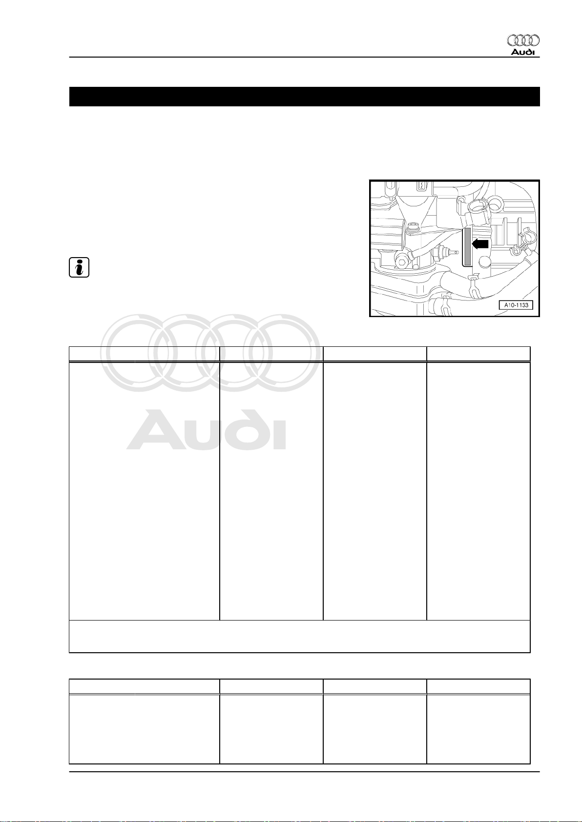
♦ The engine number (“Engine code” and “Serial number”) can
be found at the front of the joint between engine and gearbox.
♦ There is also a sticker on the cylinder head cover showing the
“engine code” and “serial number”.
♦ The engine code is also included on the vehicle data sticker.
Note
The engine code is additionally marked at the engine lifting eye
(right-side).
Audi TT 1999 ➤
1.2 Engine data
Code letters AMU APX BAM
Capacity ltr. 1.781 1.781 1.781
Power output kW at rpm 165/5900 165/5900 165/5900
Torque Nm at rpm 280/2200 … 5500 280/2200 … 5500 280/2200 … 5500
Bore ∅ in mm 81.0 81.0 81.0
Stroke mm 86.4 86.4 86.4
Compression
ratio
RON at least
Injection/ignition system Motronic Motronic Motronic
Firing order 1-4-3-2 1-4-3-2 1-4-3-2
Emissions standard TLEV EU2+D3 EU3
Exhaust gas temperature control no no yes
Turbocharging/supercharging yes yes yes
Catalytic converter yes yes yes
Knock control yes yes yes
Charge air cooling yes yes yes
Lambda control 2 probes 1 probe 2 probes
Variable valve timing no no yes
Secondary air system yes yes no
1)
•
In exceptional circumstances, fuel with not less than 95 RON can also be used, but this will cause a
loss of power.
9.0 9.0 9.0
98
1)
98
1)
98
1)
Code letters BEA BFV
Capacity ltr. 1.781 1.781
Power output kW at rpm 165/5900 176/5700
Torque Nm at rpm 280/2200 … 5500 320/2300 … 5000
Bore ∅ in mm 81 81
Stroke mm 86.4 86.4
1. Technical data 1
Page 8
Protected by copyright. Copying for private or commercial purposes, in part or in whole, is not
permitted unless authorised by AUDI AG. AUDI AG does not guarantee or accept any liability
with respect to the correctness of information in this document. Copyright by AUDI AG.
Audi TT 1999 ➤
4-cylinder 1.8 ltr. 5-valve turbocharged engine (165-176 kW), mechanics - Edition 12.2005
Code letters BEA BFV
Compression
9.0 9.0
ratio
RON at least
98
1)
98
1)
Injection/ignition system Motronic Motronic
Firing order 1-4-3-2 1-4-3-2
Emissions standard LEV EU3
Exhaust gas temperature control yes yes
Turbocharging/supercharging yes yes
Catalytic converter yes yes
Knock control yes yes
Charge air cooling yes yes
Lambda control 2 probes 2 probes
Variable valve timing yes yes
Secondary air system yes no
1)
•
In exceptional circumstances, fuel with not less than 95 RON can also be used, but this will cause a
loss of power.
2 Rep. Gr.00 - Technical data
Page 9
Protected by copyright. Copying for private or commercial purposes, in part or in whole, is not
permitted unless authorised by AUDI AG. AUDI AG does not guarantee or accept any liability
with respect to the correctness of information in this document. Copyright by AUDI AG.
4-cylinder 1.8 ltr. 5-valve turbocharged engine (165-176 kW), mechanics - Edition 12.2005
10 – Removing and installing engine
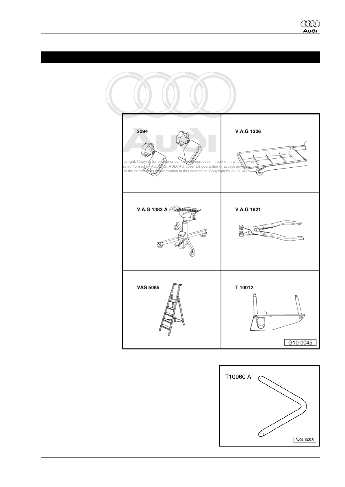
1 Removing and installing engine
1.1 Removing engine
♦ Hose clamps for hoses up
to 25 mm Ø -3094-
♦ Drip tray for workshop hoist
-VAS 6208- or V.A.G 1306-
♦ Engine and gearbox jack -
V.A.G 1383 A-
♦ Hose clip pliers -V.A.G
1921-
♦ Stepladder -VAS 5085-
♦ Engine bracket -T10012-
Audi TT 1999 ➤
♦ Locking pin -T10060 A-
1. Removing and installing engine 3
Page 10
Protected by copyright. Copying for private or commercial purposes, in part or in whole, is not
permitted unless authorised by AUDI AG. AUDI AG does not guarantee or accept any liability
with respect to the correctness of information in this document. Copyright by AUDI AG.
Audi TT 1999 ➤
4-cylinder 1.8 ltr. 5-valve turbocharged engine (165-176 kW), mechanics - Edition 12.2005
♦ Used oil collection and extraction unit -V.A.G 1782-
Procedure
Note
♦
The engine is removed from underneath together with the
gearbox.
♦
The following description corresponds to the removal and in‐
stallation on vehicles with secondary air system. Certain work
steps may not apply to vehicles without secondary air system.
♦
All heat insulation sleeves which are removed must be fitted
in the same position when installing.
♦
All cable ties which are released or cut open when removing
must be fitted in the same position when installing.
♦
Collect drained coolant in a clean container for re-use or dis‐
posal.
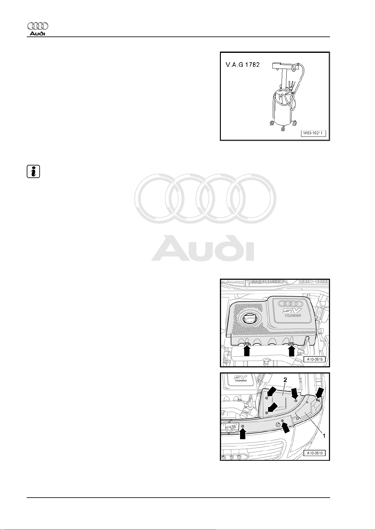
– Remove engine cover -arrows- and cover in front of intake
manifold.
– Remove covers -1- and -2- at lock carrier (left-side) and above
battery -arrows-.
4 Rep. Gr.10 - Removing and installing engine
Page 11
Protected by copyright. Copying for private or commercial purposes, in part or in whole, is not
permitted unless authorised by AUDI AG. AUDI AG does not guarantee or accept any liability
with respect to the correctness of information in this document. Copyright by AUDI AG.
4-cylinder 1.8 ltr. 5-valve turbocharged engine (165-176 kW), mechanics - Edition 12.2005
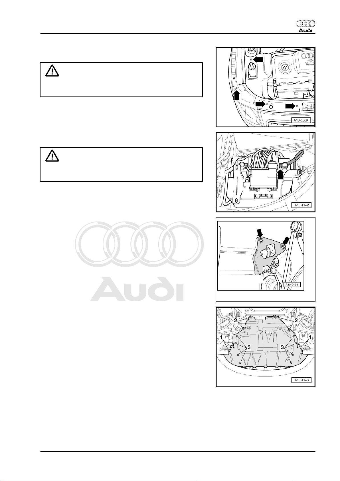
– Remove covers -1- and -2- at lock carrier (right-side) and
above coolant expansion tank -arrows-.
Caution
Observe notes on procedure for disconnecting the battery ⇒
Rep. Gr. 27 .
– With ignition switched off, disconnect battery earth cable
-arrow-.
WARNING
Hot steam or hot coolant can escape when expansion tank is
opened; cover filler cap with cloth and open carefully.
Audi TT 1999 ➤
– Open filler cap on coolant expansion tank.
– Remove both front wheels.
– Unbolt bracket for headlight range control sender in wheel
housing (left-side, top) -arrows-.
– Remove centre noise insulation -1 ... 3-.
1. Removing and installing engine 5
Page 12
Protected by copyright. Copying for private or commercial purposes, in part or in whole, is not
permitted unless authorised by AUDI AG. AUDI AG does not guarantee or accept any liability
with respect to the correctness of information in this document. Copyright by AUDI AG.
Audi TT 1999 ➤
4-cylinder 1.8 ltr. 5-valve turbocharged engine (165-176 kW), mechanics - Edition 12.2005
– Remove left noise insulation -arrows-.
– Remove right noise insulation -arrows-.
– If fitted, detach power steering line from connecting pipe for
charge air coolers -arrows-.
– Unbolt connecting pipe for charge air coolers on left side
-arrows-.
6 Rep. Gr.10 - Removing and installing engine
Page 13
Protected by copyright. Copying for private or commercial purposes, in part or in whole, is not
permitted unless authorised by AUDI AG. AUDI AG does not guarantee or accept any liability
with respect to the correctness of information in this document. Copyright by AUDI AG.
4-cylinder 1.8 ltr. 5-valve turbocharged engine (165-176 kW), mechanics - Edition 12.2005
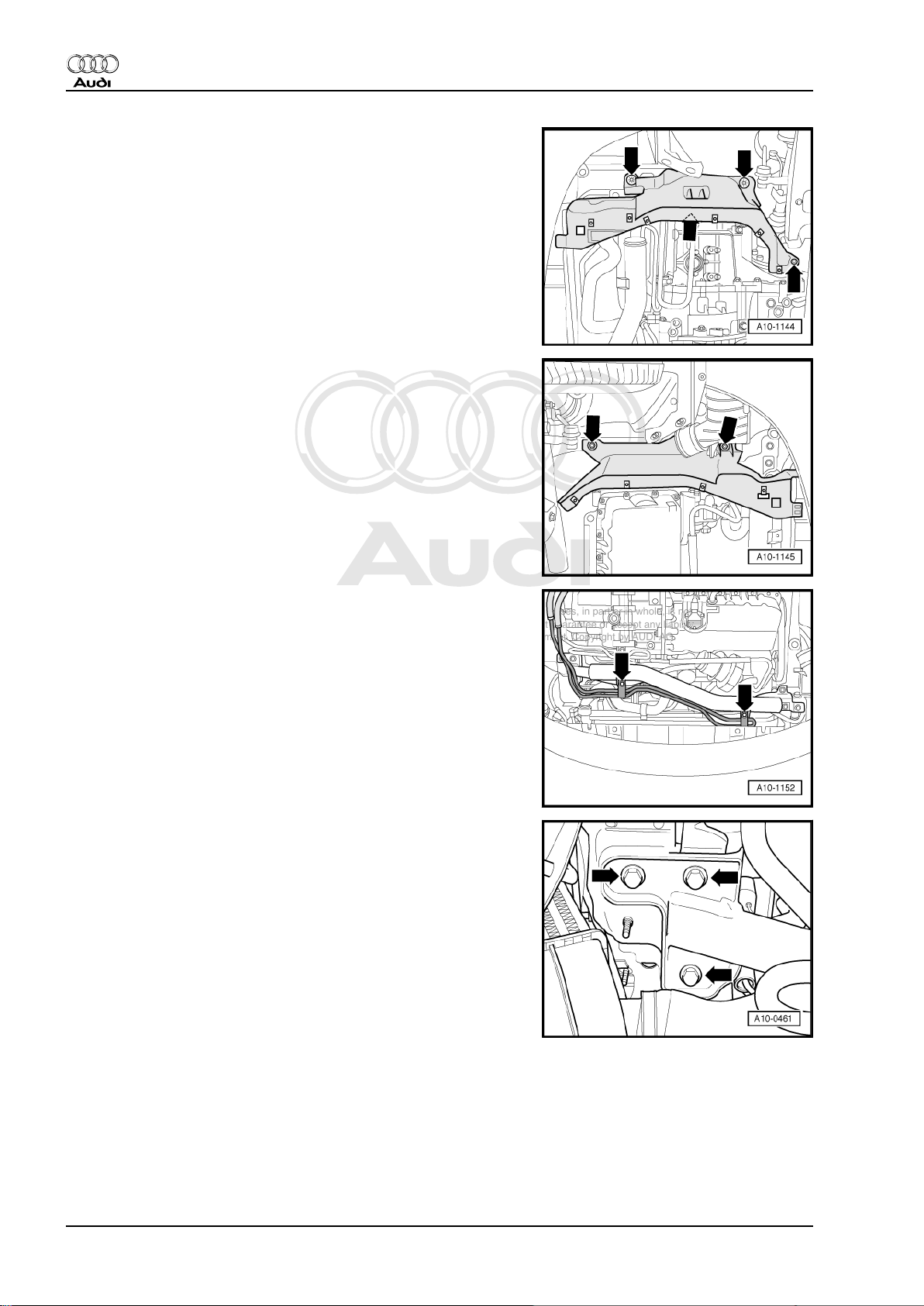
– Unbolt connecting pipe for charge air coolers on right side and
detach air intake hoses from charge air coolers -arrows-.
– Remove connecting pipe for charge air coolers.
– Place drip tray for workshop hoist -VAS 6208- under engine.
– Turn drain plug -1- on radiator anti-clockwise and drain coolant
(attach hose to connection if necessary).
– Disconnect coolant hose from radiator by pulling off retaining
clip -2- at bottom.
Audi TT 1999 ➤
– Disconnect bottom coolant hose from oil cooler -arrow-, and
drain off remaining coolant.
– Remove cross piece -1- for suspension strut -arrows-, if fitted.
1. Removing and installing engine 7
Page 14
Protected by copyright. Copying for private or commercial purposes, in part or in whole, is not
permitted unless authorised by AUDI AG. AUDI AG does not guarantee or accept any liability
with respect to the correctness of information in this document. Copyright by AUDI AG.
Audi TT 1999 ➤
4-cylinder 1.8 ltr. 5-valve turbocharged engine (165-176 kW), mechanics - Edition 12.2005
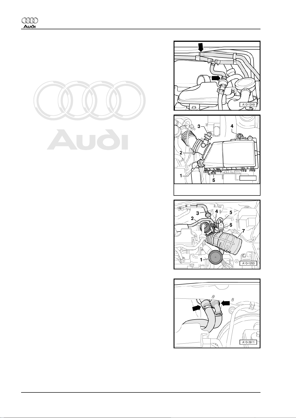
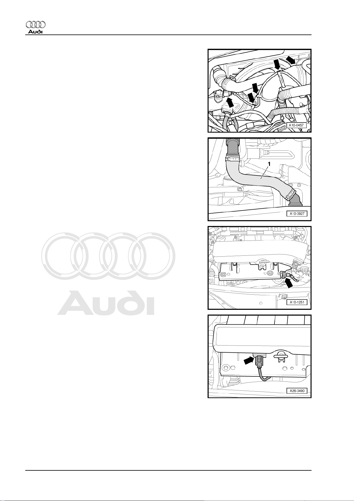
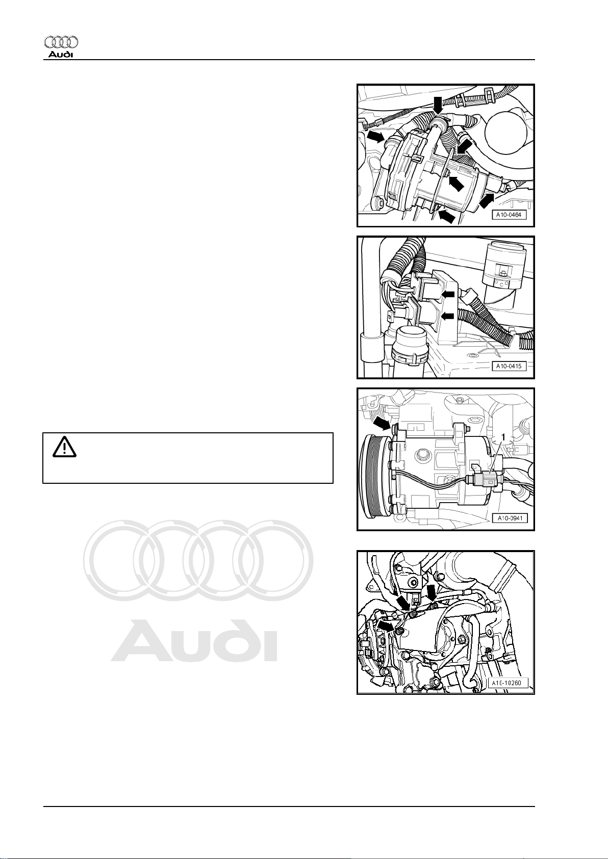
– Disconnect vacuum line and coolant pipe at locations marked
with -arrows-.
– If fitted, detach air intake hose -1- leading to secondary air
pump at air cleaner housing.
– Release hose clip -2- and detach air intake hose from air mass
meter -G70- .
– Unplug electrical connector at air mass meter -G70-
-item 3-.
– Unscrew bolts -4- and -5- and remove air cleaner housing.
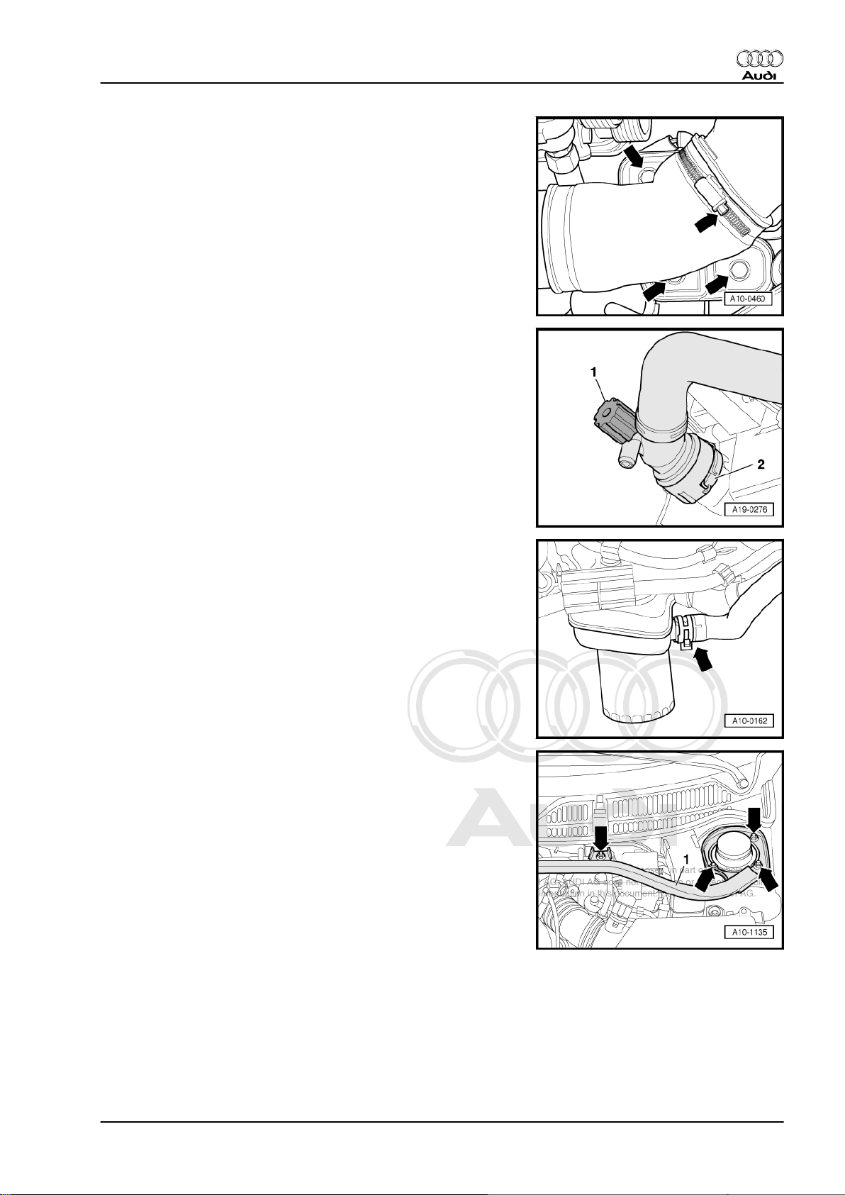
Detach air duct between air cleaner and turbocharger as follows:
– Remove pressure control valve of crankcase breather -1- and
mechanical air recirculation valve -2- from air duct.
– Detach hose going to activated charcoal filter at non-return
valve -3-.
– Disconnect electrical connector -4- at charge pressure control
solenoid valve -N75- .
– Detach hoses -5- and -6- from charge pressure control sole‐
noid valve -N75- .
– Detach air duct -7- from connection on turbocharger and pull
out hose -5-, guiding as required.
– Detach coolant hoses going to to heat exchanger at bulkhead
-arrows- by releasing retaining clips.
8 Rep. Gr.10 - Removing and installing engine
Page 15
Protected by copyright. Copying for private or commercial purposes, in part or in whole, is not
permitted unless authorised by AUDI AG. AUDI AG does not guarantee or accept any liability
with respect to the correctness of information in this document. Copyright by AUDI AG.
4-cylinder 1.8 ltr. 5-valve turbocharged engine (165-176 kW), mechanics - Edition 12.2005
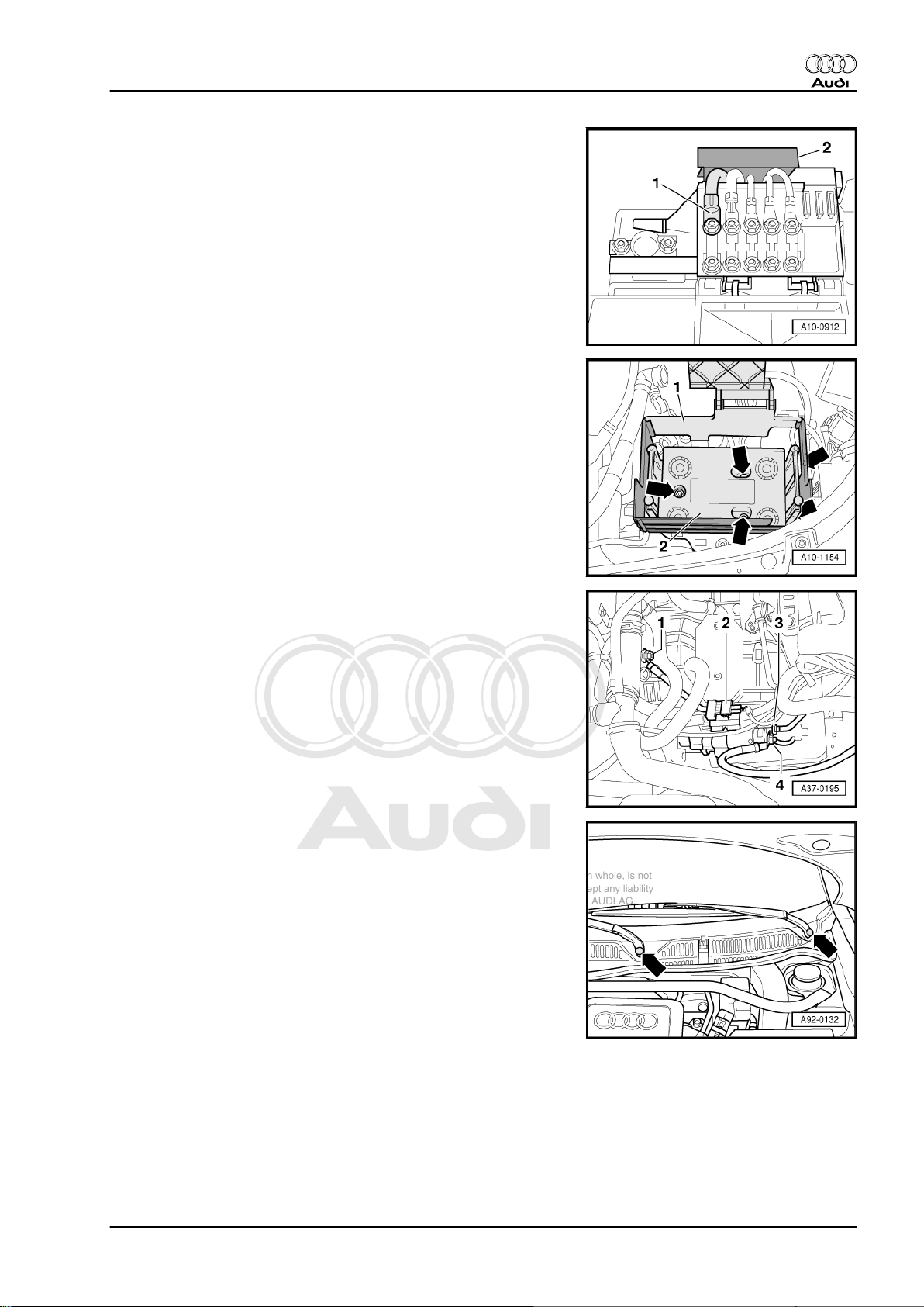
– Open cover of main fuse box.
– Unclip protective cover -2- for electrical cables.
– Unscrew black wire -1- at fuse block.
– Remove battery.
– Lift off side wall -1- together with main fuse box.
– Remove battery tray -arrows-.
Audi TT 1999 ➤
– Unscrew earth wire -1- at engine/gearbox connection.
– Detach electrical wiring -3- and -4- at starter.
– Detach electrical connector -2- from bracket and unplug.
– Disengage wiring from bracket on starter and move it clear to
the side.
– Use screwdriver to pry off caps on wiper arms -arrows- and
slacken off nuts several turns.
– Loosen wiper arms -1- from wiper shafts by tilting slightly.
– Remove nuts completely and take off wiper arms.
1. Removing and installing engine 9
Page 16
Protected by copyright. Copying for private or commercial purposes, in part or in whole, is not
permitted unless authorised by AUDI AG. AUDI AG does not guarantee or accept any liability
with respect to the correctness of information in this document. Copyright by AUDI AG.
Audi TT 1999 ➤
4-cylinder 1.8 ltr. 5-valve turbocharged engine (165-176 kW), mechanics - Edition 12.2005
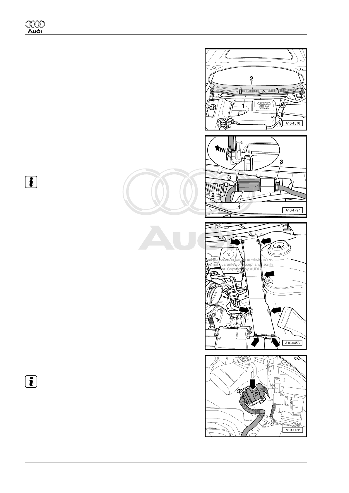
– Pull off rubber seal -1- on plenum chamber cover.
– Pull off rubber seal -2- and plenum chamber cover -3-.
– Detach the washer hose and electrical connectors at wind‐
screen washer jets.
– Lay aside plenum chamber cover (towards windscreen).
– Unclip cover -2-.
– Detach multi-pin connector -1- at engine control unit.
– Release retaining tab -arrow- and pull engine control unit for‐
wards out of the bracket.
Note
The multi-pin connector -3- remains attached to the engine control
unit.
– Open cable duct (left-side) in engine compartment -arrows-.
– Unplug electrical connector in cable duct.
– Take electrical connector out of bracket (near left-side head‐
light) and unplug connector -arrow-.
Note
On some vehicles the connector is obstructed by the headlight
(left-side). In this case, remove the headlight ⇒ Rep. Gr. 94 .
– Release wiring harness leading to engine control unit.
– Place engine control unit with wiring harness on top of engine.
– Secure the engine control unit to prevent it falling.
10 Rep. Gr.10 - Removing and installing engine
Page 17
Protected by copyright. Copying for private or commercial purposes, in part or in whole, is not
permitted unless authorised by AUDI AG. AUDI AG does not guarantee or accept any liability
with respect to the correctness of information in this document. Copyright by AUDI AG.
4-cylinder 1.8 ltr. 5-valve turbocharged engine (165-176 kW), mechanics - Edition 12.2005
– Unbolt cable support bracket from gearbox -arrows-.
Vehicles to 06.2001:
– Press locking sleeve in direction of -arrow 1- as far as stop and
lock by turning anti-clockwise in direction of -arrow 2- to re‐
lease cable end-piece for gate selector cable and gear selec‐
tor cable.
– Disengage cables from cable end-piece.
Audi TT 1999 ➤
Vehicles from 07.2001:
– Unclip retaining clip -1- from gear selector cable and retaining
clip -2- from gate selector cable.
– Pull selector cable end-pieces with selector cables off selector
shaft lever and relay lever.
All models:
– Clamp off hydraulic line to clutch slave cylinder using a hose
clamp -3094- .
– Pull out retainer towards the top -arrow- and disconnect hy‐
draulic line -1- from hose connector.
Caution
Do not press clutch pedal after disconnecting hydraulic line.
1. Removing and installing engine 11
Page 18
Protected by copyright. Copying for private or commercial purposes, in part or in whole, is not
permitted unless authorised by AUDI AG. AUDI AG does not guarantee or accept any liability
with respect to the correctness of information in this document. Copyright by AUDI AG.
Audi TT 1999 ➤
4-cylinder 1.8 ltr. 5-valve turbocharged engine (165-176 kW), mechanics - Edition 12.2005
– Unplug electrical connector at charge pressure sender -G31-
and unclip wiring from air intake hose.
– Detach air intake hose from throttle valve module -J338- .
– Remove coolant hose -1- between engine and radiator.
Vehicles with secondary air system:
– Unplug electrical connector -arrow- at secondary air inlet valve
-N112- .
Vehicles with exhaust temperature control:
– Unplug electrical connector -arrow- at exhaust gas tempera‐
ture sender 1 -G235- .
12 Rep. Gr.10 - Removing and installing engine
Page 19
Protected by copyright. Copying for private or commercial purposes, in part or in whole, is not
permitted unless authorised by AUDI AG. AUDI AG does not guarantee or accept any liability
with respect to the correctness of information in this document. Copyright by AUDI AG.
4-cylinder 1.8 ltr. 5-valve turbocharged engine (165-176 kW), mechanics - Edition 12.2005
All models:
– Unplug electrical connector -right arrow- at continued coolant
circulation pump -V51- .
– Unbolt continued coolant circulation pump -V51- from radiator
cowl -left arrows- (coolant hoses remain connected).
– Unscrew bolts for radiator cowl which are accessible from
above.
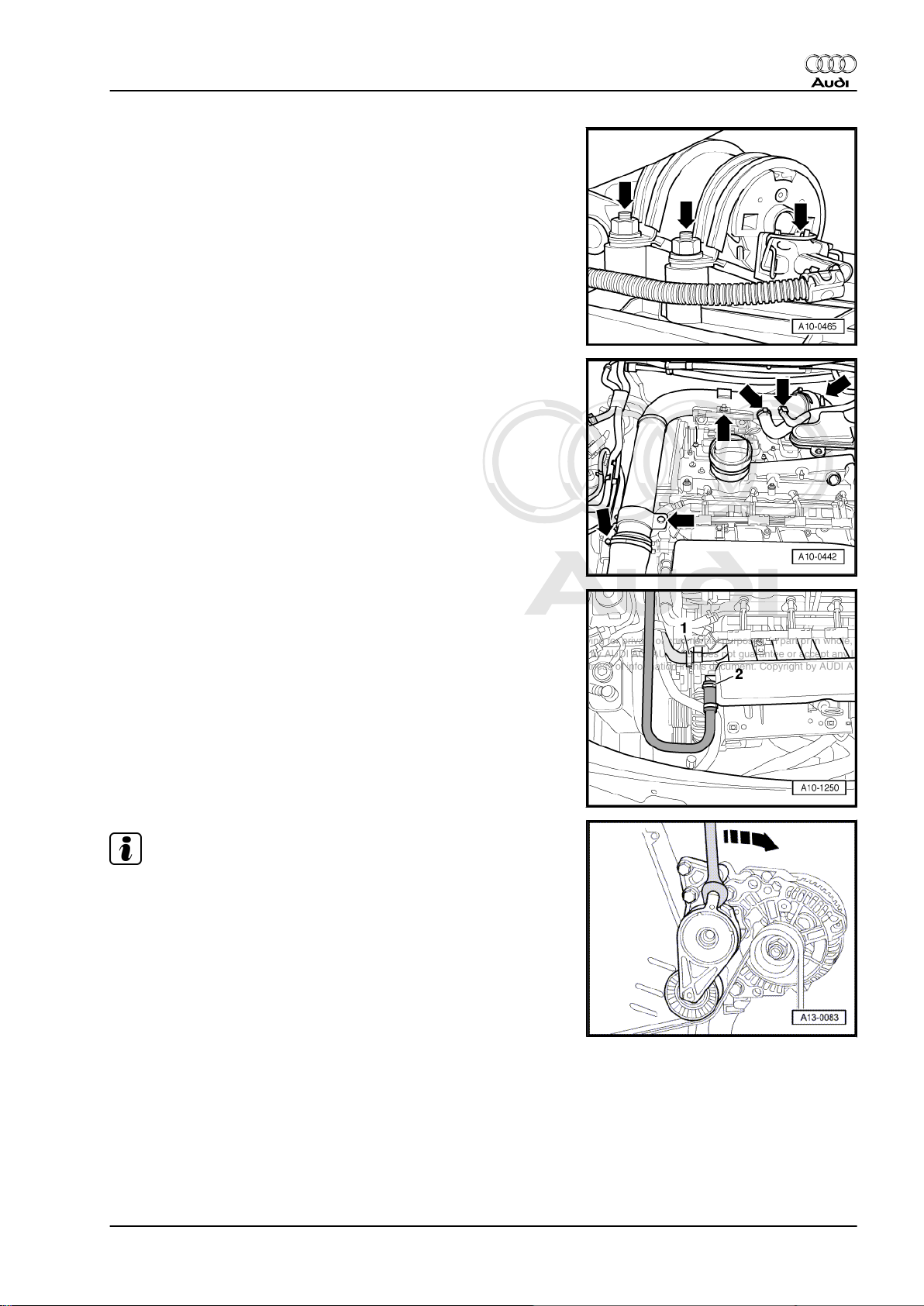
– Remove air pipe -arrows-.
Audi TT 1999 ➤
– Detach vacuum line -2- from intake manifold.
– Detach coolant hose -1- from coolant pipe/coolant expansion
tank.
Note
Before removing, mark direction of rotation of poly V-belt with
chalk or felt-tipped pen. If the belt runs in the opposite direction
when it is refitted, this can cause breakage.
– Turn the tensioner in the direction of the -arrow- to slacken the
poly V-belt.
– Remove poly V-belt.
1. Removing and installing engine 13
Page 20
Protected by copyright. Copying for private or commercial purposes, in part or in whole, is not
permitted unless authorised by AUDI AG. AUDI AG does not guarantee or accept any liability
with respect to the correctness of information in this document. Copyright by AUDI AG.
Audi TT 1999 ➤
4-cylinder 1.8 ltr. 5-valve turbocharged engine (165-176 kW), mechanics - Edition 12.2005
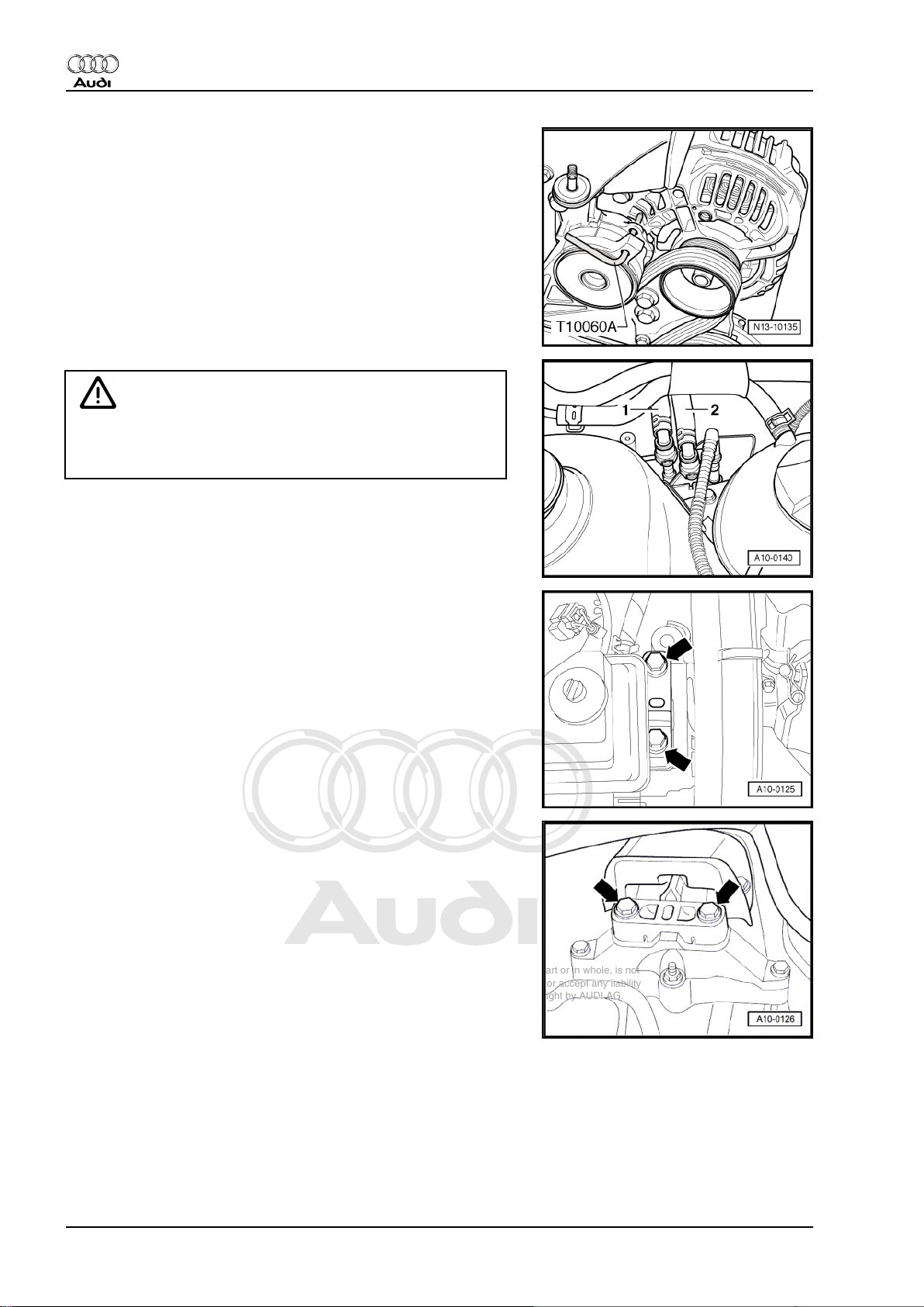
– Lock tensioner in position with locking pin -T10060 A- .
WARNING
The fuel system is pressurised. Before opening the system
place a clean cloth around the connection. Then release pres‐
sure by carefully loosening the connection.
– Disconnect fuel supply pipe -1- and fuel return pipe -2- by
pressing release tabs.
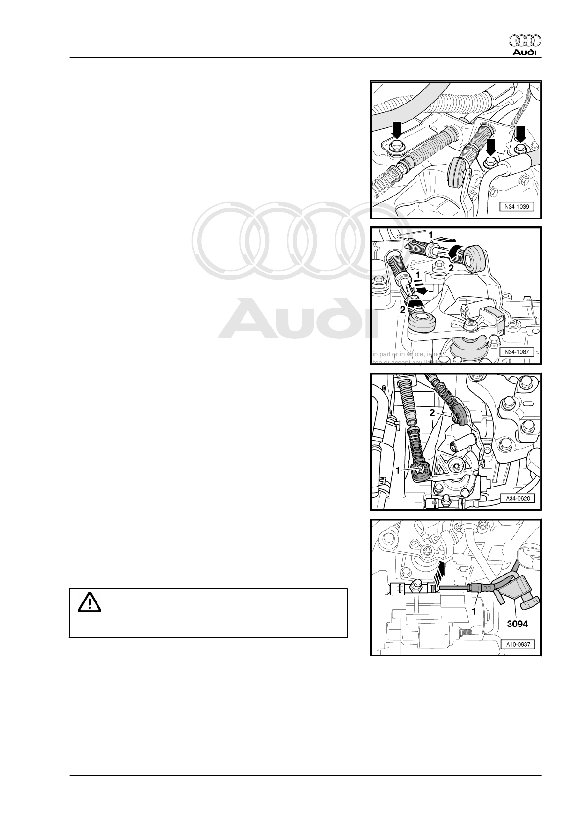
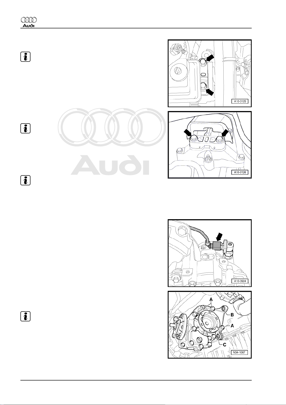
– Loosen bolts -arrows- of assembly mounting for engine ap‐
prox. 2 turns.
– Loosen bolts -arrows- of assembly mounting for gearbox ap‐
prox. 2 turns.
14 Rep. Gr.10 - Removing and installing engine
Page 21
Protected by copyright. Copying for private or commercial purposes, in part or in whole, is not
permitted unless authorised by AUDI AG. AUDI AG does not guarantee or accept any liability
with respect to the correctness of information in this document. Copyright by AUDI AG.
4-cylinder 1.8 ltr. 5-valve turbocharged engine (165-176 kW), mechanics - Edition 12.2005
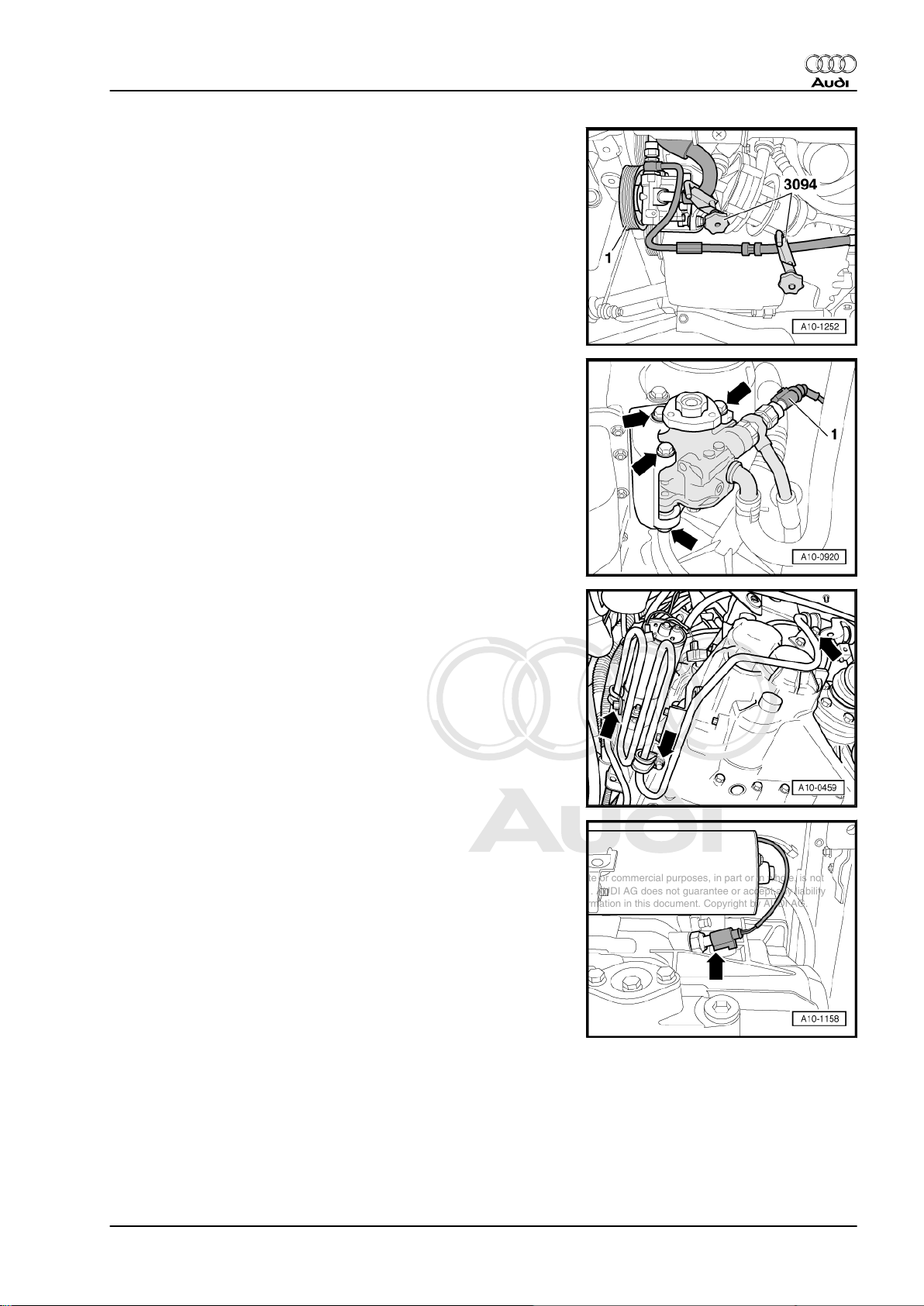
– Unbolt pulley -1- for power steering pump.
– Use hose clamps -3094- to clamp off both hydraulic hoses to
power steering pump.
– Unplug electrical connector -1- at power assisted steering
pressure switch -F88- .
– Place used oil collection and extraction unit -V.A.G 1782- un‐
der power steering pump.
– Disconnect hydraulic hoses from power steering pump.
– Unscrew power steering pump from bracket -arrows-.
Audi TT 1999 ➤
– Detach power steering cooling pipe from gearbox -arrows-.
– Unplug electrical connector -arrow- for reversing light switch -
F4- on gearbox.
1. Removing and installing engine 15
Page 22
Protected by copyright. Copying for private or commercial purposes, in part or in whole, is not
permitted unless authorised by AUDI AG. AUDI AG does not guarantee or accept any liability
with respect to the correctness of information in this document. Copyright by AUDI AG.
Audi TT 1999 ➤
4-cylinder 1.8 ltr. 5-valve turbocharged engine (165-176 kW), mechanics - Edition 12.2005
Vehicles with secondary air system:
– Unplug electrical connector at secondary air pump motor -
V101- , detach hoses and remove nuts -arrows-.
– Detach secondary air pump.
– Release wiring harness leading to body from retainers, etc.
All models:
– Detach electrical connectors -arrows- for radiator fan on bot‐
tom left of radiator cowl.
– Unscrew bolts on radiator cowl (accessible from below) and
remove radiator cowl with both fans from below.
Vehicles with air conditioning:
– Unplug electrical connector -1- for magnetic clutch of air con‐
ditioner compressor.
WARNING
The air conditioner refrigerant circuit must not be opened.
– Unscrew bolts -arrow- for air conditioner compressor.
– Tie up air conditioner compressor together with refrigerant ho‐
ses to radiator (refrigerant hoses remain connected).
– Unscrew heat shield for drive shaft (right-side) from bevel box
-arrows-.
– Unbolt drive shafts (left and right) from gearbox flange shafts.
16 Rep. Gr.10 - Removing and installing engine
Page 23
Protected by copyright. Copying for private or commercial purposes, in part or in whole, is not
permitted unless authorised by AUDI AG. AUDI AG does not guarantee or accept any liability
with respect to the correctness of information in this document. Copyright by AUDI AG.
4-cylinder 1.8 ltr. 5-valve turbocharged engine (165-176 kW), mechanics - Edition 12.2005
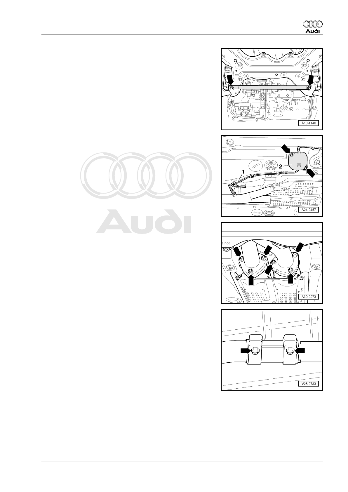
– Remove cross piece -arrows-.
Vehicles with 2 Lambda probes:
– Unbolt protective cover -2- -arrows-.
– Unplug electrical connector for Lambda probe after catalytic
converter -G130- -item 1- and move wiring clear.
Audi TT 1999 ➤
All models:
– Unbolt catalytic converter from front exhaust pipe -arrows-.
– Separate exhaust system at clamp -arrows-.
– Push the clamp back and remove the catalytic converter.
1. Removing and installing engine 17
Page 24
Protected by copyright. Copying for private or commercial purposes, in part or in whole, is not
permitted unless authorised by AUDI AG. AUDI AG does not guarantee or accept any liability
with respect to the correctness of information in this document. Copyright by AUDI AG.
Audi TT 1999 ➤
4-cylinder 1.8 ltr. 5-valve turbocharged engine (165-176 kW), mechanics - Edition 12.2005
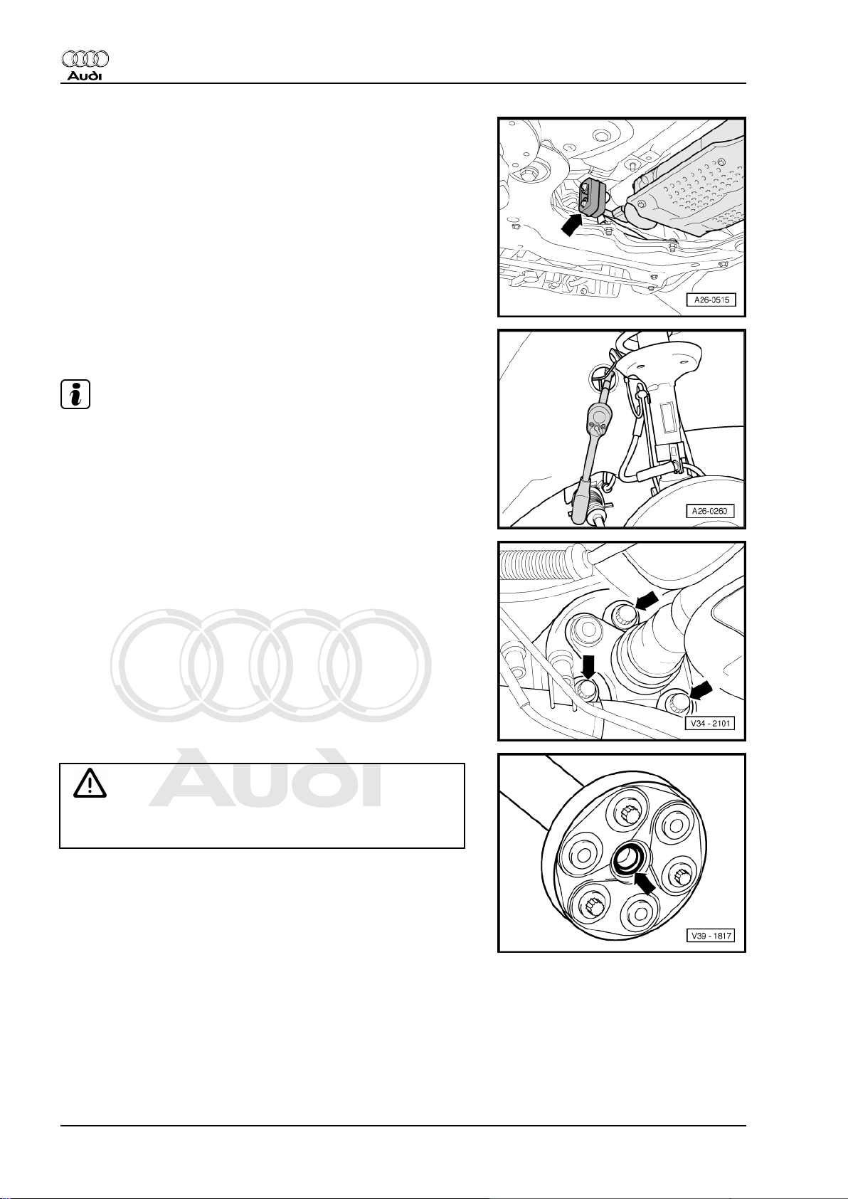
– Remove rubber mounting -arrow- for front exhaust pipe.
– Unbolt front exhaust pipe from turbocharger connection and
move to rear.
Note
♦
The top bolts securing the front exhaust pipe are accessible
through the brake pipe opening in the right wheel housing (re‐
move plug).
♦
To avoid any damage, the flexible joint in the front exhaust
pipe must not be bent more than 10°.
– Mark position of flexible coupling on bevel box.
– Unscrew propshaft with flexible coupling from bevel box
-arrows- (counter-hold using a suitable lever at the triangular
flange).
Caution
Avoid damaging the seal -arrow- in the propshaft flange when
removing. If a seal is damaged the propshaft must be renewed.
– Push propshaft horizontally as far back as possible.
18 Rep. Gr.10 - Removing and installing engine
Page 25
Protected by copyright. Copying for private or commercial purposes, in part or in whole, is not
permitted unless authorised by AUDI AG. AUDI AG does not guarantee or accept any liability
with respect to the correctness of information in this document. Copyright by AUDI AG.
4-cylinder 1.8 ltr. 5-valve turbocharged engine (165-176 kW), mechanics - Edition 12.2005
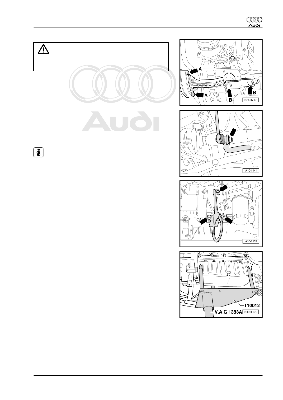
Caution
After unscrewing the bolts -A-, the engine/gearbox assembly
swings slightly forward.
– First remove bolts -A-, then bolts -B- and remove pendulum
support.
– Unbolt coupling rod from anti-roll bar -arrow- on left and right
side of vehicle.
– Push engine forward. At the same time swivel right drive shaft
towards front and tie up with wire.
– Tie up left-side drive shaft with wire.
Note
Audi TT 1999 ➤
Take care not to damage the surface coating of the drive shafts.
Vehicles with secondary air system:
– Remove bracket for secondary air pump -arrows-.
All models:
– Attach engine bracket -T10012- with nut and bolt to cylinder
block: approx. 20 Nm.
– Insert engine and gearbox jack -V.A.G 1383 A- in engine
bracket -T10012- and raise engine slightly.
1. Removing and installing engine 19
Page 26
Protected by copyright. Copying for private or commercial purposes, in part or in whole, is not
permitted unless authorised by AUDI AG. AUDI AG does not guarantee or accept any liability
with respect to the correctness of information in this document. Copyright by AUDI AG.
Audi TT 1999 ➤
4-cylinder 1.8 ltr. 5-valve turbocharged engine (165-176 kW), mechanics - Edition 12.2005
– Remove bolts -arrows- of assembly mounting on engine.
Note
To unscrew bolts for assembly mounting use stepladder VAS 5085- .
– Remove bolts -arrows- of assembly mounting on gearbox.
Note
Check that all hoses, pipes and wiring connections between en‐
gine, gearbox and body have been detached.
– Pull engine/gearbox assembly as far forward as possible, and
lower gradually using engine and gearbox jack V.A.G 1383 A- .
Note
Carefully guide engine/gearbox assembly when lowering to avoid
damage.
1.2 Separating engine and gearbox
Procedure
• Engine/gearbox assembly removed and attached to engine
bracket -T10012- .
– Unplug electrical connector -arrow- at speedometer sender -
G22- on gearbox and release wiring from retainers, etc.
Vehicles with cast bracket for bevel box:
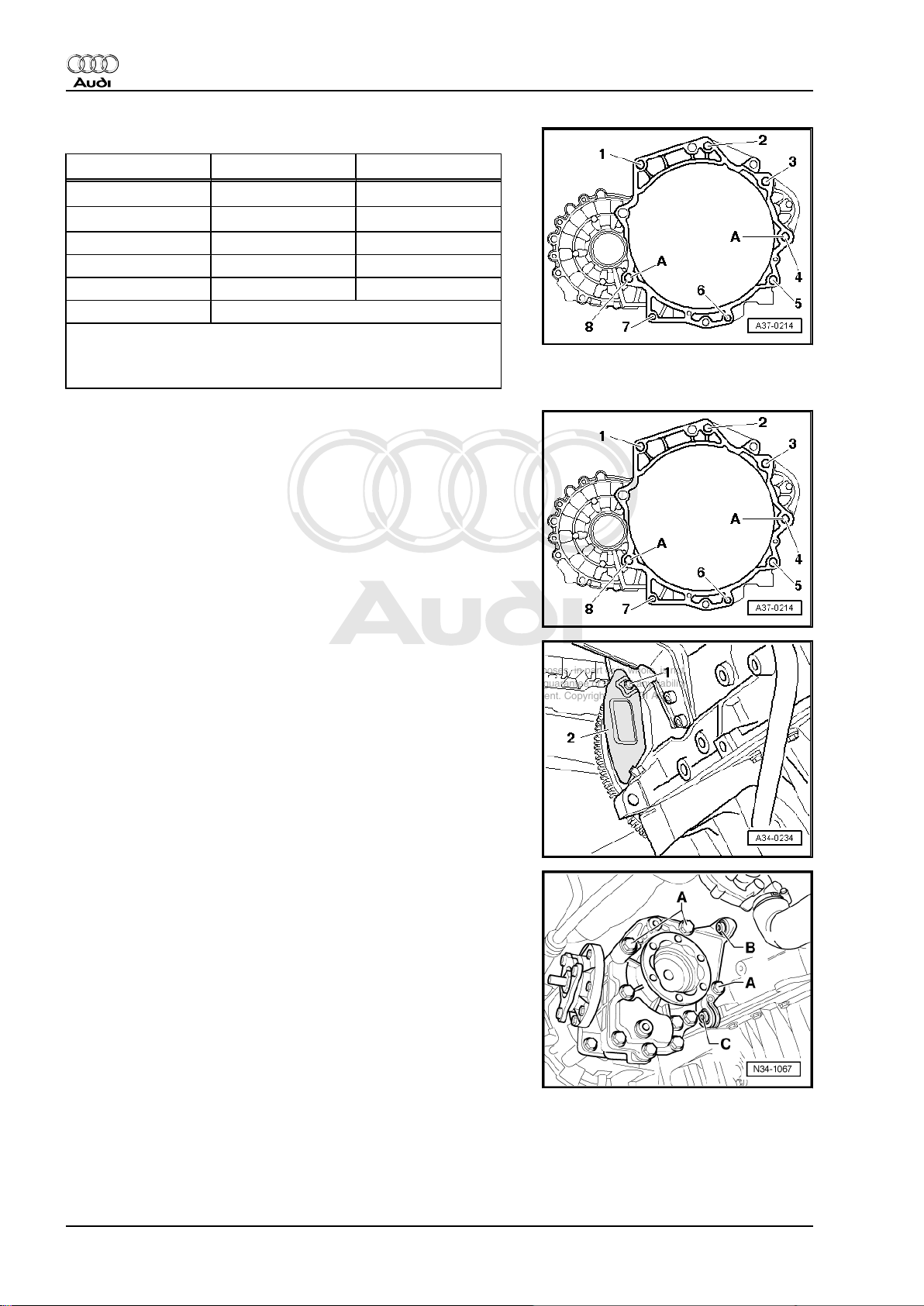
– Remove bolts -A ... C- on bracket for bevel box.
Note
Leave bracket in position. It cannot be removed at this stage.
20 Rep. Gr.10 - Removing and installing engine
Page 27
Protected by copyright. Copying for private or commercial purposes, in part or in whole, is not
permitted unless authorised by AUDI AG. AUDI AG does not guarantee or accept any liability
with respect to the correctness of information in this document. Copyright by AUDI AG.
4-cylinder 1.8 ltr. 5-valve turbocharged engine (165-176 kW), mechanics - Edition 12.2005
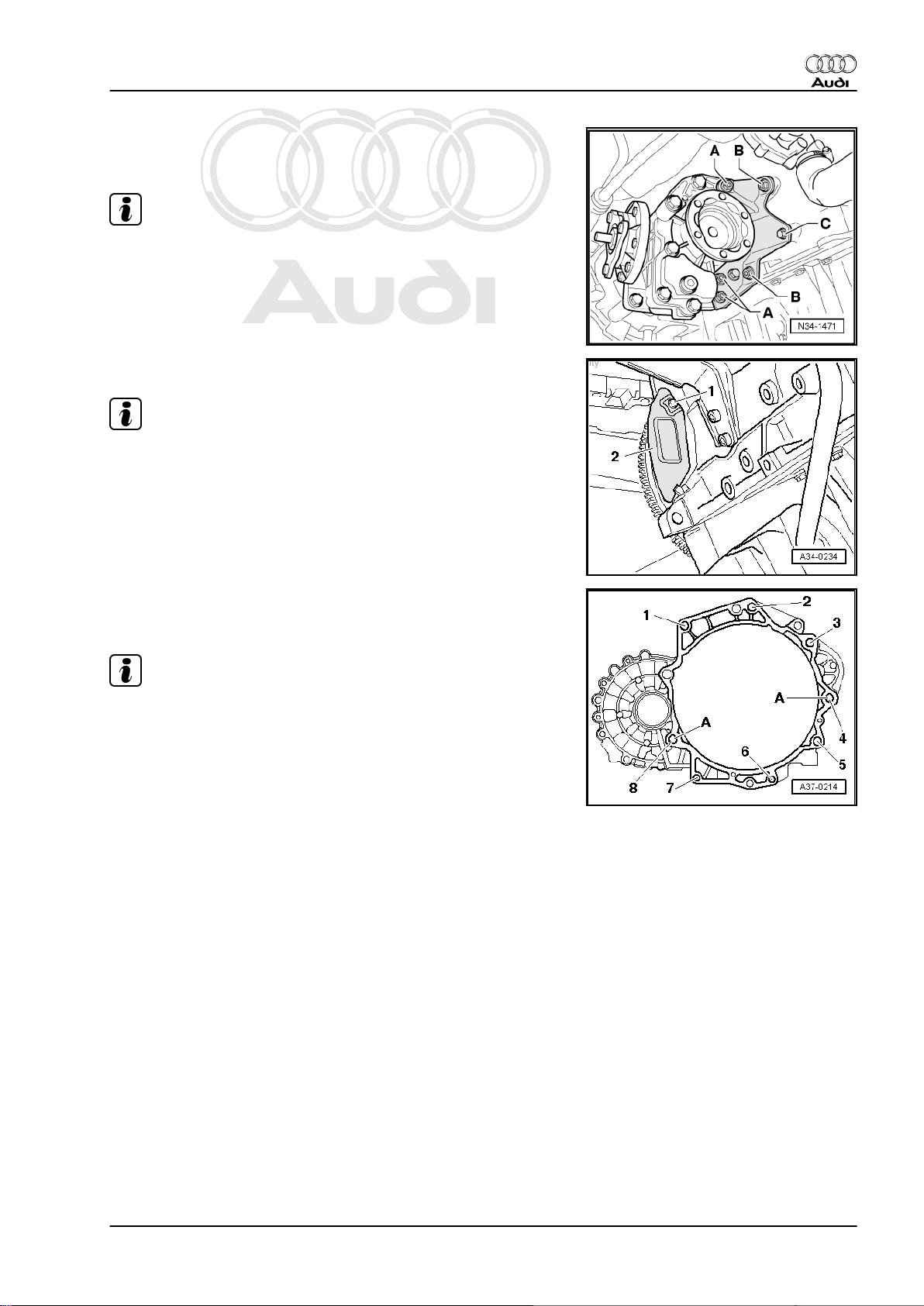
Vehicles with pressed steel bracket for bevel box:
– Remove bolts -A ... C- on bracket for bevel box.
Note
Leave bracket in position. It cannot be removed at this stage.
All models:
Note
The small cover plate -2- for the flywheel is located behind the
bevel box and is not visible with the bevel box installed. Shown in
illustration with gearbox removed.
Audi TT 1999 ➤
– Unscrew bolt -1- and lift out cover plate.
– Remove bottom engine/gearbox securing bolts -1 ... 8-.
– Separate gearbox from engine.
Note
Second mechanic is required to separate engine/gearbox as‐
sembly.
1. Removing and installing engine 21
Page 28
Protected by copyright. Copying for private or commercial purposes, in part or in whole, is not
permitted unless authorised by AUDI AG. AUDI AG does not guarantee or accept any liability
with respect to the correctness of information in this document. Copyright by AUDI AG.
Audi TT 1999 ➤
4-cylinder 1.8 ltr. 5-valve turbocharged engine (165-176 kW), mechanics - Edition 12.2005
1.3 Securing engine to assembly stand
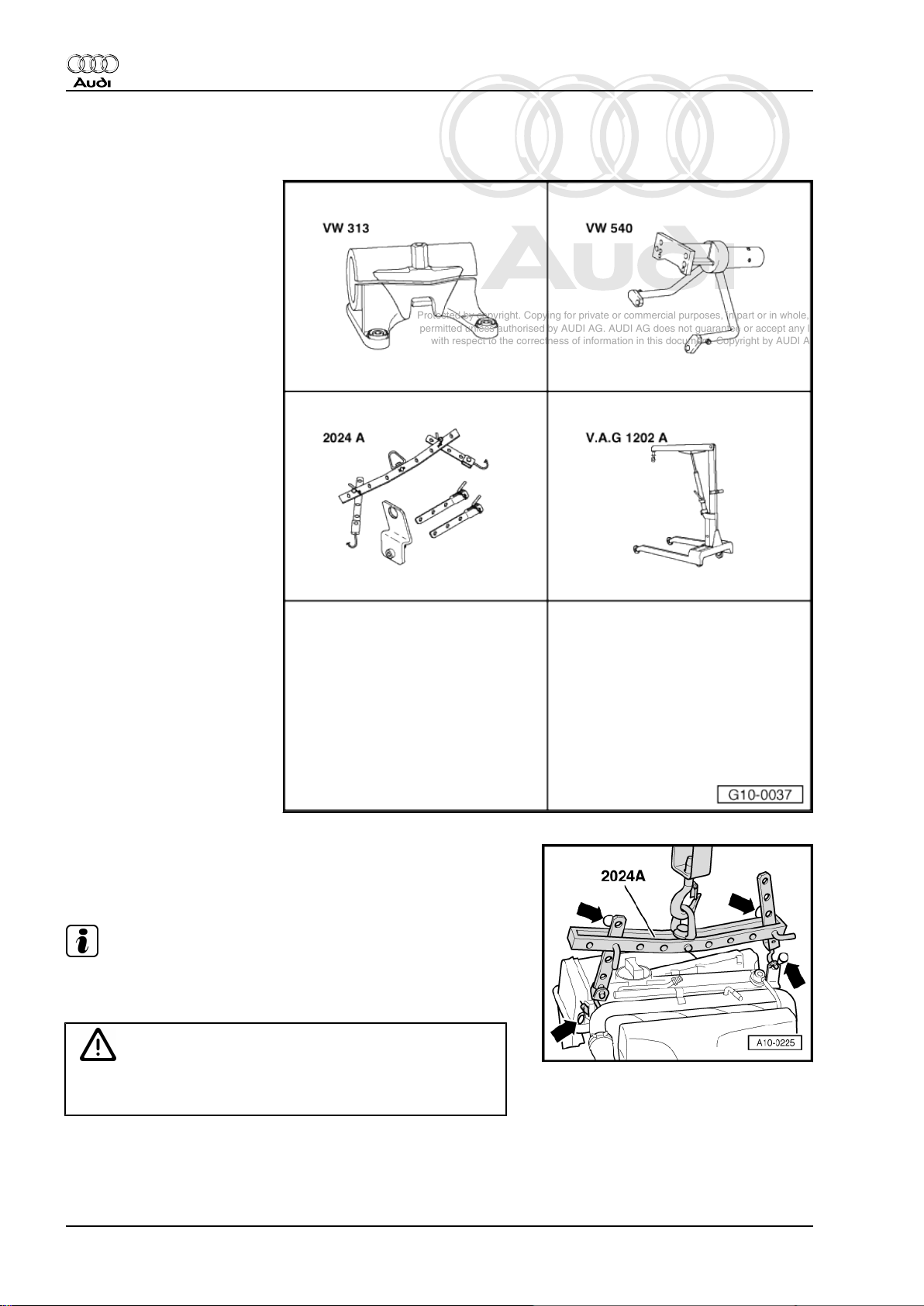
Special tools and workshop
equipment required
♦ Support clamp -VW 313-
♦ Engine and gearbox sup‐
port -VW 540-
♦ Lifting tackle -2024 A-
♦ Workshop hoist -6100- or -
V.A.G 1202 A-
Procedure
– Hook lifting tackle -2024 A- onto engine and workshop hoist
-6100- .
Note
To adjust to the centre of gravity of the assembly, the perforated
rails of the support hooks must be positioned as shown.
WARNING
The support hooks and retaining pins on the lifting tackle must
be secured with locking pins -arrows-.
– Lift engine off engine and gearbox jack -V.A.G 1383 A- using
workshop hoist -6100- .
22 Rep. Gr.10 - Removing and installing engine
Page 29
Protected by copyright. Copying for private or commercial purposes, in part or in whole, is not
permitted unless authorised by AUDI AG. AUDI AG does not guarantee or accept any liability
with respect to the correctness of information in this document. Copyright by AUDI AG.
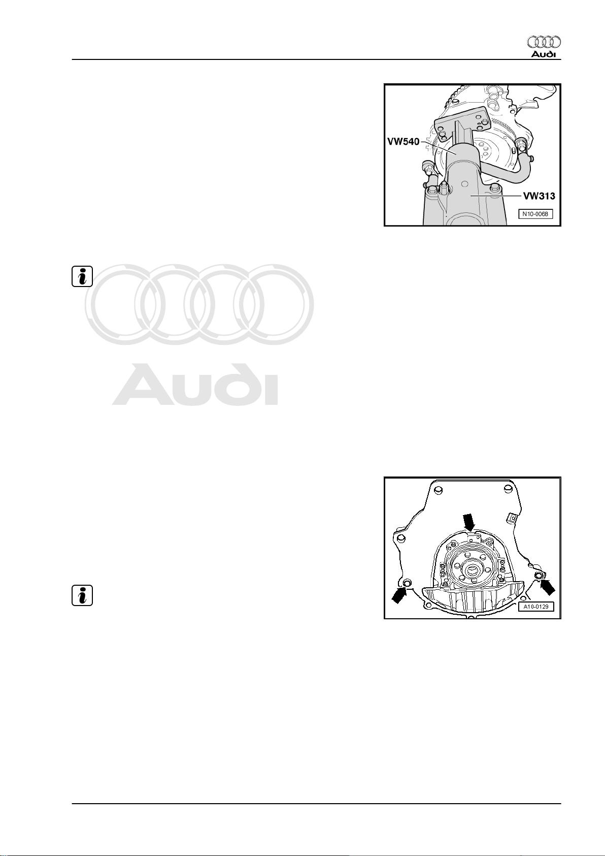
4-cylinder 1.8 ltr. 5-valve turbocharged engine (165-176 kW), mechanics - Edition 12.2005
– When carrying out repairs, secure engine to assembly stand
with engine and gearbox support -VW 540- .
1.4 Installing engine
Note
♦
On assembly, renew oil seals and gaskets as well as selflocking nuts and bolts that are tightened by turning through to
a specified angle.
♦
Hose connections and hoses for charge air system must be
free of oil and grease before assembly.
♦
Fit all heat insulation sleeves in the original position when in‐
stalling.
♦
Secure all hose connections with the correct type of hose clips
(same as original equipment) ⇒ Parts catalogue.
♦
Fit all cable ties in the original positions when installing.
– Check whether dowel sleeves for centring the engine/gearbox
assembly are fitted in the cylinder block; install dowel sleeves
if necessary.
– Engage intermediate plate on sealing flange and slip onto
dowel sleeves -arrows-.
Audi TT 1999 ➤
– Check that clutch plate is correctly centred.
– Check clutch release bearing for wear, renew if necessary.
– Lightly grease clutch release bearing, release bearing guide
sleeve and splines on input shaft with grease for clutch plate
splines -G 000 100- .
Note
♦
Tightening torques apply only to lightly greased, oiled,
phosphated or black-finished nuts and bolts.
♦
Additional lubricant such as engine oil or gearbox oil may be
used, but do not use lubricant containing graphite.
♦
Do not use degreased parts.
♦
Tolerance for tightening torques ± 15 %.
– Fit bracket for bevel box before fitting engine/gearbox securing
bolts.
– Use new securing bolts.
1. Removing and installing engine 23
Page 30
Protected by copyright. Copying for private or commercial purposes, in part or in whole, is not
permitted unless authorised by AUDI AG. AUDI AG does not guarantee or accept any liability
with respect to the correctness of information in this document. Copyright by AUDI AG.
Audi TT 1999 ➤
4-cylinder 1.8 ltr. 5-valve turbocharged engine (165-176 kW), mechanics - Edition 12.2005
Securing engine to gearbox
Item
1, 2
3 1), 4
1)
1)
Bolt
2
Nm
M12x55 80
M12x165 80
5 M10x105 40
6, 7 M10x50 40
8 M12x70 80
A Dowel sleeves for centralising
1)
•
Bolt with M8 stud
2)
•
Renew bolts.
– Install new engine/gearbox securing bolts accessible from be‐
low.
– Push in small cover plate -2- for flywheel behind bevel box in
such a way that lug at bottom engages into cylinder block and
secure with bolt -1-.
Vehicles with cast bracket for bevel box:
– Fit bolts -A ... C- for bevel box bracket. Note tightening se‐
quence:
1. Initially tighten bolts -A- to 3 Nm.
2. Tighten bolts -B- and -C- to 35 Nm.
3. Tighten bolts -A- to 45 Nm.
24 Rep. Gr.10 - Removing and installing engine
Page 31

Protected by copyright. Copying for private or commercial purposes, in part or in whole, is not
permitted unless authorised by AUDI AG. AUDI AG does not guarantee or accept any liability
with respect to the correctness of information in this document. Copyright by AUDI AG.
4-cylinder 1.8 ltr. 5-valve turbocharged engine (165-176 kW), mechanics - Edition 12.2005
Vehicles with pressed steel bracket for bevel box:
– Fit bolts -A ... C- for bevel box bracket. Note tightening se‐
quence:
1. Initially tighten bolts -A- to 3 Nm.
2. Tighten bolts -B- to 35 Nm.
3. Tighten bolt -C- to 22 Nm.
4. Tighten bolts -A- to 45 Nm.
All models:
– Guide engine/gearbox assembly into the body.
– Tighten bolts securing engine mounting to engine support
-arrows- initially hand-tight.
Audi TT 1999 ➤
– Tighten bolts securing gearbox mounting to gearbox support
-arrows- initially hand-tight.
– Use new securing bolts.
Note
The bolts are tightened to final torque only after adjusting the en‐
gine mountings ⇒ page 29 .
– Remove engine bracket -T10012- from engine.
– Bolt drive shafts to flange shafts of gearbox ⇒ Rep. Gr. 40 .
Note
Drive shafts must be installed prior to further assembly.
– Secure coupling rod to anti-roll bar ⇒ Rep. Gr. 40 .
– Secure pendulum support at gearbox -arrows B-.
– Use new securing bolts.
1. Removing and installing engine 25
Page 32

Protected by copyright. Copying for private or commercial purposes, in part or in whole, is not
permitted unless authorised by AUDI AG. AUDI AG does not guarantee or accept any liability
with respect to the correctness of information in this document. Copyright by AUDI AG.
Audi TT 1999 ➤
4-cylinder 1.8 ltr. 5-valve turbocharged engine (165-176 kW), mechanics - Edition 12.2005
Caution
Avoid damaging the seal -arrow- in the propshaft flange when
installing. If a seal is damaged the propshaft must be renewed.
– Push engine/gearbox assembly towards bulkhead; the journal
of the bevel box must be simultaneously inserted horizontally
and carefully into the flange of the propshaft.
– Secure pendulum support to subframe -arrows A-.
– Use new securing bolts.
– Secure propshaft with flexible coupling to bevel box -arrows-
⇒ Rep. Gr. 39 .
– Install catalytic converter and front exhaust pipe
⇒ page 196 .
– Install exhaust system and align it free of stress
⇒ page 201 .
– Install cross piece; note marking “L” or “Links” for left side of
vehicle.
– Use new securing bolts.
– Knock back bushes for securing bolts slightly to facilitate in‐
stallation of power steering pump and air conditioner com‐
pressor.
– Install power steering pump ⇒ Rep. Gr. 48 .
– Install secondary air pump ⇒ page 223 .
– Install air conditioner compressor ⇒ Rep. Gr. 87 .
26 Rep. Gr.10 - Removing and installing engine
Page 33

Protected by copyright. Copying for private or commercial purposes, in part or in whole, is not
permitted unless authorised by AUDI AG. AUDI AG does not guarantee or accept any liability
with respect to the correctness of information in this document. Copyright by AUDI AG.
4-cylinder 1.8 ltr. 5-valve turbocharged engine (165-176 kW), mechanics - Edition 12.2005
– Push the hydraulic line -1- for clutch slave cylinder into the
hose connector and lock it with the catch.
Caution
The clutch pedal must not be depressed prior to bleeding the
clutch system.
– Detach hose clamp -3094- .
– Bleed clutch hydraulics ⇒ Rep. Gr. 30 .
Remaining installation steps are carried out in reverse sequence;
note the following:
– Install cable support bracket and selector cables ⇒ Rep. Gr.
34 .
– Adjust selector cables ⇒ Rep. Gr. 34 .
– Install battery tray and battery ⇒ Rep. Gr. 27 .
– Install poly V-belt ⇒ page 34 .
– Adjust assembly mountings ⇒ page 29 .
– Connect vacuum hoses ⇒ page 157 .
– Install cross piece for suspension strut ⇒ Rep. Gr. 40 .
– Electrical connections and routing ⇒ Current flow diagrams,
Electrical fault finding and Fitting locations.
– Observe notes on procedures required after connecting bat‐
tery ⇒ Rep. Gr. 27 .
– Install and adjust wiper arms ⇒ Rep. Gr. 92 .
– Check oil level ⇒ page 133 .
– Fill cooling system ⇒ page 138 .
Audi TT 1999 ➤
Note
♦
Drained-off coolant may only be used again if the original cyl‐
inder head and cylinder block are re-installed.
♦
Contaminated or dirty coolant must not be used again.
Caution
Never use battery charging equipment for boost starting. There
is danger of damaging the vehicle's control units.
1. Removing and installing engine 27
Page 34

Protected by copyright. Copying for private or commercial purposes, in part or in whole, is not
permitted unless authorised by AUDI AG. AUDI AG does not guarantee or accept any liability
with respect to the correctness of information in this document. Copyright by AUDI AG.
Audi TT 1999 ➤
4-cylinder 1.8 ltr. 5-valve turbocharged engine (165-176 kW), mechanics - Edition 12.2005
Tightening torques
Component Nm
Bolts/nuts M6 9
M8 20
M10 45
M12 65
Except for the following:
Radiator cowl to radiator 10
Pendulum support to: Gearbox
Subframe
40 + 90°
20 + 90°
Drive shaft heat shield to bevel box 25
Rear cross piece to subframe
Connecting pipe for charge air coolers to lon‐
30 + 90°
20
gitudinal member
Hose clips for air hoses 3.5
1)
•
Renew bolts.
2)
•
90° = one quarter turn.
3)
•
Install using locking fluid; for locking fluid refer to ⇒ Parts
catalogue .
1)2)
1)2)
1)2)3)
28 Rep. Gr.10 - Removing and installing engine
Page 35

Protected by copyright. Copying for private or commercial purposes, in part or in whole, is not
permitted unless authorised by AUDI AG. AUDI AG does not guarantee or accept any liability
with respect to the correctness of information in this document. Copyright by AUDI AG.
4-cylinder 1.8 ltr. 5-valve turbocharged engine (165-176 kW), mechanics - Edition 12.2005
2 Adjusting assembly mountings
2.1 Checking adjustment
Procedure
– Take off engine cover panel -arrows-.
– Unscrew bolt -1- and remove cover over coolant expansion
tank -arrow-.
Audi TT 1999 ➤
– Remove air pipe -arrows-.
2. Adjusting assembly mountings 29
Page 36

Protected by copyright. Copying for private or commercial purposes, in part or in whole, is not
permitted unless authorised by AUDI AG. AUDI AG does not guarantee or accept any liability
with respect to the correctness of information in this document. Copyright by AUDI AG.
Audi TT 1999 ➤
4-cylinder 1.8 ltr. 5-valve turbocharged engine (165-176 kW), mechanics - Edition 12.2005
– Detach power steering reservoir above engine mounting
(right-side) and move to side.
• Both bolt heads -b- must be flush with the edge of the support
arm -2-.
• The distance -a- between engine mounting -1- and support
arm -2- must be 13 mm.
– Check gap -a- with 12 mm iron bar (or support bridge -2011- ).
• The bar must be easy to insert.
Installation is carried out in the reverse order; note the following:
Note
♦
Hose connections and hoses for charge air system must be
free of oil and grease before assembly.
♦
Secure all hose connections with the correct type of hose clips
(same as original equipment) ⇒ Parts catalogue.
Tightening torque
Component Nm
Hose clips for air hoses 3.5
2.2 Adjusting assembly mountings
Special tools and workshop equipment required
♦ Support bracket -10-222 A-
Procedure
If the distance measured is too small or too great, proceed as
follows:
– Remove covers -1- and -2- at lock carrier (left-side) and above
battery -arrows-.
30 Rep. Gr.10 - Removing and installing engine
Page 37

Protected by copyright. Copying for private or commercial purposes, in part or in whole, is not
permitted unless authorised by AUDI AG. AUDI AG does not guarantee or accept any liability
with respect to the correctness of information in this document. Copyright by AUDI AG.
4-cylinder 1.8 ltr. 5-valve turbocharged engine (165-176 kW), mechanics - Edition 12.2005
– Remove cover -1- (right-side) on lock carrier
-bottom arrows-.
Note
Disregard -item 2-.
– If fitted, detach air intake hose -1- leading to secondary air
pump at air cleaner housing.
– Release hose clip -2- and detach air intake hose from air mass
meter -G70- .
– Unplug electrical connector at air mass meter -G70-
-item 3-.
– Unscrew bolts -4- and -5- and remove air cleaner housing.
Audi TT 1999 ➤
– Set up support bracket -10-222 A- on top surface of panel
flange.
• The spindles face forwards.
– Attach hooks of spindles to engine lifting eyes.
– Lift the engine evenly a short distance with both spindles.
– Remove bolts -arrows- of assembly mounting on engine.
2. Adjusting assembly mountings 31
Page 38

Protected by copyright. Copying for private or commercial purposes, in part or in whole, is not
permitted unless authorised by AUDI AG. AUDI AG does not guarantee or accept any liability
with respect to the correctness of information in this document. Copyright by AUDI AG.
Audi TT 1999 ➤
4-cylinder 1.8 ltr. 5-valve turbocharged engine (165-176 kW), mechanics - Edition 12.2005
– Remove bolts -arrows- of assembly mounting on gearbox.
– Renew all 4 bolts one after the other and hand-tighten.
– Loosen bolts -b- for support arms on right and left sides ap‐
prox. 2 turns.
– Use lever to adjust engine until distance -a- between engine
mounting -1- and support arm -2- is 13 mm.
• It should be possible to insert the 12 mm iron bar (or support
bridge -2011- ) easily.
• Both bolt heads -b- must be flush with the edge of the support
arm.
– Tighten the bolts -b- for engine assembly mounting.
– Ensure that the edges of the support arm (on the gearbox as‐
sembly mounting) -a- and gearbox mounting -b- are parallel.
– Tighten the bolts for gearbox assembly mounting.
Installation is carried out in the reverse order; note the following:
Note
Secure all hose connections with the correct type of hose clips
(same as original equipment) ⇒ Parts catalogue.
Tightening torques
Component Nm
Support arm to: Gearbox support
Engine support
1)
•
Renew bolts.
2)
•
90° = one quarter turn.
60 + 90°
60 + 90°
1)2)
1)2)
32 Rep. Gr.10 - Removing and installing engine
Page 39

Protected by copyright. Copying for private or commercial purposes, in part or in whole, is not
permitted unless authorised by AUDI AG. AUDI AG does not guarantee or accept any liability
with respect to the correctness of information in this document. Copyright by AUDI AG.
4-cylinder 1.8 ltr. 5-valve turbocharged engine (165-176 kW), mechanics - Edition 12.2005
13 – Crankshaft group
1 Servicing work on pulley end
1.1 Poly V-belt drive - exploded view of components
Note
The illustration shows the poly V-belt drive on vehicles with air conditioner.
1 - Poly V-belt
❑ Routing of belt on vehi‐
cles without air condi‐
tioner ⇒ page 34
❑ Routing of belt on vehi‐
cles with air conditioner
⇒ page 34
❑ Double-sided poly V-
belt on vehicles with air
conditioner
❑ Before removing, mark
direction of rotation with
chalk or felt-tipped pen.
If the belt runs in the op‐
posite direction when it
is refitted, this can
cause breakage.
❑ Check for wear
❑ Do not kink
❑ Removing and installing
⇒ page 34
Audi TT 1999 ➤
2 - 23 Nm
3 - Poly V-belt tensioner
❑ Turn with open-end
spanner to slacken poly
V-belt ⇒ page 36
4 - Vibration damper
❑ With pulley for poly V-
belt
❑ Removing and installing
⇒ page 37
5 - 45 Nm
6 - 23 Nm
7 - Alternator
❑ Removing and installing ⇒ Rep. Gr. 27
❑ To facilitate attachment of alternator, knock back threaded bushes for alternator securing bolts slightly
8 - Air conditioner compressor
❑ Removing and installing ⇒ Rep. Gr. 87
❑ After detaching, secure compressor to lock carrier using wire or similar. Do not leave it suspended from
refrigerant pipes.
❑ Do not unscrew or disconnect refrigerant hoses or pipes.
1. Servicing work on pulley end 33
Page 40

Protected by copyright. Copying for private or commercial purposes, in part or in whole, is not
permitted unless authorised by AUDI AG. AUDI AG does not guarantee or accept any liability
with respect to the correctness of information in this document. Copyright by AUDI AG.
Audi TT 1999 ➤
4-cylinder 1.8 ltr. 5-valve turbocharged engine (165-176 kW), mechanics - Edition 12.2005
❑ To facilitate attachment of air conditioner, knock back threaded bushes for securing bolts slightly
9 - Spacer bush
10 - Bracket for ancillaries
❑ Removing and installing ⇒ page 38
11 - 45 Nm
12 - 23 Nm
13 - 23 Nm
14 - Power steering pump
❑ Removing and installing ⇒ Rep. Gr. 48
❑ To facilitate positioning of power steering pump, drive back threaded bush for securing bolt slightly at
bracket
15 - Pulley for power steering pump
16 - 23 Nm
17 - Special bolt
❑ For correct version refer to ⇒ Parts catalogue
❑ If bolt strength rating is 8.8, renew bolt and tighten to 10 Nm + 90° further
❑ If bolt strength rating is 10.9, tighten to 40 Nm
Routing of poly V-belt on vehicles without air conditioner
Routing of poly V-belt on vehicles with air conditioner
Note
A double-sided poly V-belt is fitted on engines with A/C compres‐
sor.
1.2 Removing and installing poly V-belt
Special tools and workshop equipment required
34 Rep. Gr.13 - Crankshaft group
Page 41

Protected by copyright. Copying for private or commercial purposes, in part or in whole, is not
permitted unless authorised by AUDI AG. AUDI AG does not guarantee or accept any liability
with respect to the correctness of information in this document. Copyright by AUDI AG.
4-cylinder 1.8 ltr. 5-valve turbocharged engine (165-176 kW), mechanics - Edition 12.2005
♦ Locking pin -T10060 A-
Removing
– Take off engine cover panel -arrows-.
Audi TT 1999 ➤
– Unscrew bolt -1- and remove cover over coolant expansion
tank -arrow-.
– Remove air pipe -arrows-.
1. Servicing work on pulley end 35
Page 42

Protected by copyright. Copying for private or commercial purposes, in part or in whole, is not
permitted unless authorised by AUDI AG. AUDI AG does not guarantee or accept any liability
with respect to the correctness of information in this document. Copyright by AUDI AG.
Audi TT 1999 ➤
4-cylinder 1.8 ltr. 5-valve turbocharged engine (165-176 kW), mechanics - Edition 12.2005
Note
Before removing, mark direction of rotation of poly V-belt with
chalk or felt-tipped pen. If the belt runs in the opposite direction
when it is refitted, this can cause breakage.
– Turn the tensioner in the direction of the -arrow- to slacken the
poly V-belt.
– Lock tensioner in position with locking pin -T10060 A- .
– Remove centre noise insulation -1 ... 3-.
36 Rep. Gr.13 - Crankshaft group
Page 43

Protected by copyright. Copying for private or commercial purposes, in part or in whole, is not
permitted unless authorised by AUDI AG. AUDI AG does not guarantee or accept any liability
with respect to the correctness of information in this document. Copyright by AUDI AG.
4-cylinder 1.8 ltr. 5-valve turbocharged engine (165-176 kW), mechanics - Edition 12.2005
– Remove right noise insulation -arrows-.
– Remove poly V-belt.
Installing
Installation is carried out in the reverse order; note the following:
Note
♦
Before fitting poly V-belt, make sure all mechanical units (al‐
ternator, air conditioner compressor, power steering pump)
are firmly in position.
♦
Hose connections and hoses for charge air system must be
free of oil and grease before assembly.
♦
Secure all hose connections with the correct type of hose clips
(same as original equipment) ⇒ Parts catalogue.
– Fit poly V-belt onto crankshaft pulley, power steering pump
pulley and then onto alternator pulley.
– Release pressure from tensioner and remove locking pin -
T10060 A- .
– Check poly V-belt for proper seating.
• Routing of poly V-belt on vehicles without air conditioner
⇒ page 34 .
• Routing of poly V-belt on vehicles with air conditioner
⇒ page 34 .
– Start engine and check that belt runs properly.
Tightening torque
Audi TT 1999 ➤
Component Nm
Hose clips for air hoses 3.5
1.3 Removing and installing vibration damp‐
er
Removing
– Remove poly V-belt ⇒ page 34 .
– Unbolt vibration damper; counterhold on centre bolt with ring
spanner.
1. Servicing work on pulley end 37
Page 44

Protected by copyright. Copying for private or commercial purposes, in part or in whole, is not
permitted unless authorised by AUDI AG. AUDI AG does not guarantee or accept any liability
with respect to the correctness of information in this document. Copyright by AUDI AG.
Audi TT 1999 ➤
4-cylinder 1.8 ltr. 5-valve turbocharged engine (165-176 kW), mechanics - Edition 12.2005
Installing
Installation is carried out in the reverse order; note the following:
– When installing the vibration damper, use only genuine bolts
(same as original equipment): ⇒ Parts catalogue .
• The vibration damper can only be installed in one position. The
hole -arrow- in the vibration damper must be located over the
projection on the toothed belt sprocket.
– Install poly V-belt ⇒ page 34 .
Tightening torque
Component Nm
Vibration damper
to crankshaft
1)
•
Renew bolts.
Bolt strength rating 8.8
10 + 90°
Bolt strength rating 10.9 40
1)2)
• 90° equals a 1/4 turn.
1.4 Removing and installing bracket for an‐
cillaries
Special tools and workshop equipment required
♦ Hose clamps for hoses up to 25 mm Ø -3094-
♦ Used oil collection and extraction unit -V.A.G 1782-
38 Rep. Gr.13 - Crankshaft group
Page 45

Protected by copyright. Copying for private or commercial purposes, in part or in whole, is not
permitted unless authorised by AUDI AG. AUDI AG does not guarantee or accept any liability
with respect to the correctness of information in this document. Copyright by AUDI AG.
4-cylinder 1.8 ltr. 5-valve turbocharged engine (165-176 kW), mechanics - Edition 12.2005
Removing
– Remove engine cover -arrows- and cover in front of intake
manifold.
– Remove covers -1- and -2- at lock carrier (left-side) and above
battery -arrows-.
Audi TT 1999 ➤
– Remove covers -1- and -2- at lock carrier (right-side) and
above coolant expansion tank -arrows-.
Caution
Observe notes on procedure for disconnecting the battery ⇒
Rep. Gr. 27 .
– Disconnect earth wire at battery with ignition switched off.
– Remove poly V-belt ⇒ page 34 .
– Unbolt bracket for headlight range control sender in wheel
housing (left-side, top) -arrows-.
1. Servicing work on pulley end 39
Page 46

Protected by copyright. Copying for private or commercial purposes, in part or in whole, is not
permitted unless authorised by AUDI AG. AUDI AG does not guarantee or accept any liability
with respect to the correctness of information in this document. Copyright by AUDI AG.
Audi TT 1999 ➤
4-cylinder 1.8 ltr. 5-valve turbocharged engine (165-176 kW), mechanics - Edition 12.2005
– Remove left noise insulation -arrows-.
– If fitted, detach power steering line from connecting pipe for
charge air coolers -arrows-.
– Unbolt connecting pipe for charge air coolers on left side
-arrows-.
– Unbolt connecting pipe for charge air coolers on right side and
detach air intake hoses from charge air coolers -arrows-.
– Remove connecting pipe for charge air coolers.
40 Rep. Gr.13 - Crankshaft group
Page 47

Protected by copyright. Copying for private or commercial purposes, in part or in whole, is not
permitted unless authorised by AUDI AG. AUDI AG does not guarantee or accept any liability
with respect to the correctness of information in this document. Copyright by AUDI AG.
4-cylinder 1.8 ltr. 5-valve turbocharged engine (165-176 kW), mechanics - Edition 12.2005
– Unbolt pulley -1- for power steering pump.
– Use hose clamps -3094- to clamp off both hydraulic hoses to
power steering pump.
– Unplug electrical connector -1- at power assisted steering
pressure switch -F88- .
– Place used oil collection and extraction unit -V.A.G 1782- un‐
der power steering pump.
– Disconnect hydraulic hoses from power steering pump.
– Detach power steering pump from bracket for ancillaries
-arrows-.
Audi TT 1999 ➤
Vehicles with secondary air system:
– Unplug electrical connector at secondary air pump motor -
V101- , detach hoses and remove nuts -arrows-.
– Detach secondary air pump.
Vehicles with exhaust temperature control:
– Unplug electrical connector -arrow- at exhaust gas tempera‐
ture sender 1 -G235- .
1. Servicing work on pulley end 41
Page 48

Protected by copyright. Copying for private or commercial purposes, in part or in whole, is not
permitted unless authorised by AUDI AG. AUDI AG does not guarantee or accept any liability
with respect to the correctness of information in this document. Copyright by AUDI AG.
Audi TT 1999 ➤
4-cylinder 1.8 ltr. 5-valve turbocharged engine (165-176 kW), mechanics - Edition 12.2005
All models:
– Remove bolts -2- and -3- and detach retaining plate -4- from
dipstick guide tube.
– Disengage coolant hose -1- from retaining plate.
– Move retaining plate to the side (hoses remain connected).
– Detach vacuum line -2- from intake manifold.
Note
Disregard -item 1-.
– Unplug electrical connector -2-.
– Unscrew electrical wire -1- from alternator.
– Unscrew clamp and move electrical wiring clear.
– Unscrew bolts -arrows-.
– Detach alternator and guide it towards right out of engine com‐
partment.
42 Rep. Gr.13 - Crankshaft group
Page 49

Protected by copyright. Copying for private or commercial purposes, in part or in whole, is not
permitted unless authorised by AUDI AG. AUDI AG does not guarantee or accept any liability
with respect to the correctness of information in this document. Copyright by AUDI AG.
4-cylinder 1.8 ltr. 5-valve turbocharged engine (165-176 kW), mechanics - Edition 12.2005
Vehicles with air conditioning:
– Unscrew radiator fan (right-side) from radiator cowl, take out
downwards and tie up to body (wiring remains connected).
– Unplug electrical connector -1- for magnetic clutch of air con‐
ditioner compressor.
WARNING
The air conditioner refrigerant circuit must not be opened.
– Unscrew bolts -arrow- for air conditioner compressor.
Note
To prevent damage to the refrigerant lines, ensure that the pipes
and hoses are not stretched, kinked or bent.
– Lower air conditioner compressor and tie up to lock carrier.
Audi TT 1999 ➤
All models:
– Remove poly V-belt tensioner -arrows-.
1. Servicing work on pulley end 43
Page 50

Protected by copyright. Copying for private or commercial purposes, in part or in whole, is not
permitted unless authorised by AUDI AG. AUDI AG does not guarantee or accept any liability
with respect to the correctness of information in this document. Copyright by AUDI AG.
Audi TT 1999 ➤
4-cylinder 1.8 ltr. 5-valve turbocharged engine (165-176 kW), mechanics - Edition 12.2005
– Unscrew bolts -A ... F- and remove bracket for ancillaries.
Installing
Installation is carried out in the reverse order; note the following:
Note
♦
Hose connections and hoses for charge air system must be
free of oil and grease before assembly.
♦
Secure all hose connections with the correct type of hose clips
(same as original equipment) ⇒ Parts catalogue.
– Tighten bolts in the sequence -A ... F-.
– Drive back the respective bushes for securing bolts slightly to
facilitate installation of alternator, power steering pump and air
conditioner compressor.
– Install power steering pump ⇒ Rep. Gr. 48 .
– Install air conditioner compressor ⇒ Rep. Gr. 87 .
– Install alternator ⇒ Rep. Gr. 27 .
– Install secondary air pump ⇒ page 223 .
– Observe notes on procedures required after connecting bat‐
tery ⇒ Rep. Gr. 27 .
– Install poly V-belt ⇒ page 34 .
Tightening torques
Component Nm
Bracket for ancillaries to cylinder block 45
Tensioner for poly V-belt to bracket for ancilla‐
23
ries
Radiator fan to radiator cowl 10
Connecting pipe for charge air coolers to longi‐
tudinal member
20
Pulley to power steering pump 23
44 Rep. Gr.13 - Crankshaft group
Page 51

Protected by copyright. Copying for private or commercial purposes, in part or in whole, is not
permitted unless authorised by AUDI AG. AUDI AG does not guarantee or accept any liability
with respect to the correctness of information in this document. Copyright by AUDI AG.
4-cylinder 1.8 ltr. 5-valve turbocharged engine (165-176 kW), mechanics - Edition 12.2005
1.5 Toothed belt - exploded view of components
1 - Engine support
2 - 45 Nm
3 - Toothed belt cover (top)
❑ To remove toothed belt
cover, it may be neces‐
sary to unbolt bracket
for coolant return line
(for turbocharger).
❑ Engage carefully in cen‐
tre toothed belt cover
when installing
4 - Toothed belt
❑ Before removing, mark
direction of rotation with
chalk or felt-tipped pen.
If the belt runs in the op‐
posite direction when it
is refitted, this can
cause breakage
❑ Check for wear
❑ Removing ⇒ page 47
❑ Installing (adjusting
valve timing)
⇒ page 51
5 - Idler roller
6 - 27 Nm
7 - 65 Nm
❑ Use counterhold tool
-3036- when loosening
and tightening
⇒ page 46
8 - Camshaft sprocket for ex‐
haust camshaft
❑ Remove toothed belt prior to removing and installing ⇒ page 47
❑ Installation position ⇒ page 46
9 - Tensioning roller
10 - Washer
11 - Tensioner for toothed belt
12 - O-ring
❑ Renew
❑ Lubricate with coolant additive Plus -G 012 A8F A1- prior to installing
13 - Coolant pump
❑ Removing and installing ⇒ page 141
14 - 15 Nm
15 - Crankshaft sprocket
❑ Contact surface between sprocket and crankshaft must be free of oil
❑ Can only be installed in one position
Audi TT 1999 ➤
16 - 90 Nm + 90° (1/4 turn) further
❑ Renew
1. Servicing work on pulley end 45
Page 52

Protected by copyright. Copying for private or commercial purposes, in part or in whole, is not
permitted unless authorised by AUDI AG. AUDI AG does not guarantee or accept any liability
with respect to the correctness of information in this document. Copyright by AUDI AG.
Audi TT 1999 ➤
4-cylinder 1.8 ltr. 5-valve turbocharged engine (165-176 kW), mechanics - Edition 12.2005
❑ Do not lubricate with oil
❑ Use counterhold tool -3415- when loosening and tightening ⇒ page 46
17 - 15 Nm
18 - 25 Nm
19 - Toothed belt cover (centre)
20 - Toothed belt cover (bottom)
21 - 10 Nm
❑ Install using locking fluid; for locking fluid refer to ⇒ Parts catalogue
Loosening and tightening bolt for camshaft sprocket
– Use counterhold tool -3036- when loosening and tightening
central bolt.
Installation position of camshaft sprocket
• The thinner web of the camshaft sprocket faces outwards
-arrows- and the marking “OT” for TDC is visible from the front.
Removing and installing crankshaft sprocket
– Use counterhold tool -3415- when loosening and tightening
central bolt.
46 Rep. Gr.13 - Crankshaft group
Page 53

Protected by copyright. Copying for private or commercial purposes, in part or in whole, is not
permitted unless authorised by AUDI AG. AUDI AG does not guarantee or accept any liability
with respect to the correctness of information in this document. Copyright by AUDI AG.
4-cylinder 1.8 ltr. 5-valve turbocharged engine (165-176 kW), mechanics - Edition 12.2005
1.6 Removing and installing toothed belt
Special tools and workshop
equipment required
♦ Support bracket -10-222 A-
♦ Tensioning bolt -T10092-
♦ Locking pin -T40011-
Audi TT 1999 ➤
Removing
– Remove poly V-belt ⇒ page 34 .
– Remove cover -1- (left-side) on lock carrier -bottom arrows-.
Note
Disregard -item 2-.
1. Servicing work on pulley end 47
Page 54

Protected by copyright. Copying for private or commercial purposes, in part or in whole, is not
permitted unless authorised by AUDI AG. AUDI AG does not guarantee or accept any liability
with respect to the correctness of information in this document. Copyright by AUDI AG.
Audi TT 1999 ➤
4-cylinder 1.8 ltr. 5-valve turbocharged engine (165-176 kW), mechanics - Edition 12.2005
– Remove cover -1- (right-side) on lock carrier
-bottom arrows-.
Note
Disregard -item 2-.
– Remove poly V-belt tensioner -arrows-.
Rest-of-world vehicles:
– Detach coolant expansion tank -1-, power steering reservoir
-2- and activated charcoal filter -3-. Hoses remain connected.
USA models:
– Detach coolant expansion tank -1-, power steering reservoir
-2- and vacuum reservoir -3-. Hoses remain connected.
48 Rep. Gr.13 - Crankshaft group
Page 55

Protected by copyright. Copying for private or commercial purposes, in part or in whole, is not
permitted unless authorised by AUDI AG. AUDI AG does not guarantee or accept any liability
with respect to the correctness of information in this document. Copyright by AUDI AG.
4-cylinder 1.8 ltr. 5-valve turbocharged engine (165-176 kW), mechanics - Edition 12.2005
All models:
WARNING
The fuel system is pressurised. Before opening the system
place a clean cloth around the connection. Then release pres‐
sure by carefully loosening the connection.
– Disconnect fuel supply pipe -1- and fuel return pipe -2- by
pressing release tabs.
– Detach vacuum line -2- from intake manifold.
Note
Disregard -item 1-.
Audi TT 1999 ➤
– Turn crankshaft to “TDC”: With engine installed ⇒ page 53 ,
with engine removed ⇒ page 56 .
– Unbolt vibration damper; counterhold on centre bolt with ring
spanner.
– Unbolt lower and centre toothed belt covers -arrows-.
1. Servicing work on pulley end 49
Page 56

Protected by copyright. Copying for private or commercial purposes, in part or in whole, is not
permitted unless authorised by AUDI AG. AUDI AG does not guarantee or accept any liability
with respect to the correctness of information in this document. Copyright by AUDI AG.
Audi TT 1999 ➤
4-cylinder 1.8 ltr. 5-valve turbocharged engine (165-176 kW), mechanics - Edition 12.2005
– Set up support bracket -10-222 A- on top surface of panel
flange.
• The spindle is located at the front.
– Attach hook on spindle to engine lifting eye (right-side).
– Lift engine slightly with spindle of support bracket -10-222 A- .
– Tie up coolant expansion tank and power assisted steering
reservoir on engine support bracket.
– Unbolt engine mounting and connecting bracket from body
and from engine support -arrows-.
– Remove engine mounting.
– Remove bolts for engine support -arrows- but do not take out
the engine support.
Note
To remove the bolts for the engine support, raise or lower the
engine slightly as necessary via the spindle on support bracket
-10-222 A- .
– Screw tensioning bolt -T10092- into toothed belt tensioner.
– Compress piston of tensioner just far enough so that the piston
can be locked with locking pin -T40011- .
Note
Bend locking pin -T40011- approx. 90° so it can be inserted more
easily.
– Mark the rotation direction of toothed belt with chalk or a felt-
tipped pen.
– Pull out toothed belt through space between engine support
and cylinder block.
50 Rep. Gr.13 - Crankshaft group
Page 57

Protected by copyright. Copying for private or commercial purposes, in part or in whole, is not
permitted unless authorised by AUDI AG. AUDI AG does not guarantee or accept any liability
with respect to the correctness of information in this document. Copyright by AUDI AG.
4-cylinder 1.8 ltr. 5-valve turbocharged engine (165-176 kW), mechanics - Edition 12.2005
Installing (adjusting valve timing)
Caution
When turning the camshaft, the crankshaft must not be at
“TDC”. Otherwise, there is a risk of damage to valves and pis‐
ton crowns.
– Check that marking on camshaft sprocket is aligned with mark‐
ing on cylinder head cover -arrows-.
– Check again that crankshaft is positioned at TDC -arrow-.
– Fit toothed belt onto crankshaft sprocket, noting direction of
rotation.
– Fit toothed belt onto remaining sprockets in the sequence:
coolant pump, tensioning roller, camshaft sprocket.
Audi TT 1999 ➤
– Remove tensioning bolt -T10092- .
– Remove locking pin -T40011- from tensioner.
• Piston of toothed belt tensioner is released.
– Turn crankshaft at central bolt on toothed belt sprocket two
revolutions in direction of engine rotation and check whether
camshaft and crankshaft markings align with their respective
reference points.
– Install toothed belt cover.
Installation is carried out in the reverse order; note the following:
Note
Secure all hose connections with the correct type of hose clips
(same as original equipment) ⇒ Parts catalogue.
– Install vibration damper ⇒ page 37 .
1. Servicing work on pulley end 51
Page 58

Protected by copyright. Copying for private or commercial purposes, in part or in whole, is not
permitted unless authorised by AUDI AG. AUDI AG does not guarantee or accept any liability
with respect to the correctness of information in this document. Copyright by AUDI AG.
Audi TT 1999 ➤
4-cylinder 1.8 ltr. 5-valve turbocharged engine (165-176 kW), mechanics - Edition 12.2005
– Install engine support -arrows-.
– Adjust assembly mountings ⇒ page 29 .
– Install poly V-belt ⇒ page 34 .
– Install coolant expansion tank, power steering reservoir and
activated charcoal filter.
Tightening torques
Component Nm
Toothed belt cover (bottom) to cylinder block
Toothed belt cover (centre) to cylinder block
10
10
1)
1)
Engine support to cylinder block 45
Connecting bracket to body/engine mounting 25
Engine mounting to body
Tensioner for poly V-belt to bracket for ancilla‐
40 + 90°
2)3)
23
ries
1)
•
Install using locking fluid; for locking fluid refer to ⇒ Parts
catalogue .
2)
•
Renew bolts.
3)
•
90° = one quarter turn.
1.7 Removing toothed belt from camshaft sprocket
Special tools and workshop equipment required
♦ Stud M5x55, nut and large washer
Removing
– Turn crankshaft to “TDC”: With engine installed ⇒ page 53 ,
with engine removed ⇒ page 56 .
– Screw stud M5x55 -item 1- into toothed belt tensioner.
– Screw nut -3- with large washer -2- onto stud.
– Carefully tension piston of tensioner until it is just possible to
detach toothed belt from camshaft sprocket.
Note
Take care not to compress tensioner too far.
– Remove toothed belt from camshaft sprocket.
52 Rep. Gr.13 - Crankshaft group
Page 59

Protected by copyright. Copying for private or commercial purposes, in part or in whole, is not
permitted unless authorised by AUDI AG. AUDI AG does not guarantee or accept any liability
with respect to the correctness of information in this document. Copyright by AUDI AG.
4-cylinder 1.8 ltr. 5-valve turbocharged engine (165-176 kW), mechanics - Edition 12.2005
Fitting (adjusting valve timing)
Caution
When turning the camshaft, the crankshaft must not be at
“TDC”. Otherwise, there is a risk of damage to valves and pis‐
ton crowns.
– Check that marking on camshaft sprocket is aligned with mark‐
ing on cylinder head cover -arrows-.
– Check again that crankshaft is positioned at TDC -arrow-.
Audi TT 1999 ➤
– Fit toothed belt onto camshaft sprocket.
– Release piston of toothed belt tensioner and unscrew stud
-1-.
– Turn crankshaft at central bolt on toothed belt sprocket two
revolutions in direction of engine rotation and check whether
camshaft and crankshaft markings align with their respective
reference points.
1.8 Positioning crankshaft at “TDC” with en‐
gine installed
Procedure
– Take off engine cover panel -arrows-.
1. Servicing work on pulley end 53
Page 60

Protected by copyright. Copying for private or commercial purposes, in part or in whole, is not
permitted unless authorised by AUDI AG. AUDI AG does not guarantee or accept any liability
with respect to the correctness of information in this document. Copyright by AUDI AG.
Audi TT 1999 ➤
4-cylinder 1.8 ltr. 5-valve turbocharged engine (165-176 kW), mechanics - Edition 12.2005
– Unscrew bolt -1- and remove cover over coolant expansion
tank -arrow-.
– Remove air pipe -arrows-.
– Unplug electrical connector -arrow- at Hall sender -G40- .
– Remove toothed belt cover (top).
– Remove front left cover -arrows-.
54 Rep. Gr.13 - Crankshaft group
Page 61

Protected by copyright. Copying for private or commercial purposes, in part or in whole, is not
permitted unless authorised by AUDI AG. AUDI AG does not guarantee or accept any liability
with respect to the correctness of information in this document. Copyright by AUDI AG.
4-cylinder 1.8 ltr. 5-valve turbocharged engine (165-176 kW), mechanics - Edition 12.2005
– If fitted, detach air hose -1- (leading to secondary air pump) at
air cleaner housing.
– Release hose clip -2- and detach air intake hose from air mass
meter -G70- .
– Unplug electrical connector at air mass meter -G70-
-item 3-.
– Unscrew bolts -4- and -5- and remove air cleaner housing.
– Pull out sealing plug at gearbox.
– Remove centre noise insulation -1 ... 3-.
Audi TT 1999 ➤
– Remove right noise insulation -arrows-.
– Pull out sealing plug at gearbox.
– Turn crankshaft at central bolt on crankshaft sprocket in di‐
rection of engine rotation to TDC mark -arrow-.
1. Servicing work on pulley end 55
Page 62

Protected by copyright. Copying for private or commercial purposes, in part or in whole, is not
permitted unless authorised by AUDI AG. AUDI AG does not guarantee or accept any liability
with respect to the correctness of information in this document. Copyright by AUDI AG.
Audi TT 1999 ➤
4-cylinder 1.8 ltr. 5-valve turbocharged engine (165-176 kW), mechanics - Edition 12.2005
• At the same time the marking on the front of the camshaft
sprocket must align with the marking on the cylinder head
cover -arrows-.
– Rotate crankshaft one turn further if necessary.
Installation is carried out in the reverse order; note the following:
Note
♦
Hose connections and hoses for charge air system must be
free of oil and grease before assembly.
♦
Secure all hose connections with the correct type of hose clips
(same as original equipment) ⇒ Parts catalogue.
Tightening torque
Component Nm
Hose clips for air hoses 3.5
1.9 Positioning crankshaft at “TDC” with en‐
gine removed
Procedure
• Toothed belt cover (top section) removed
– Turn crankshaft at central bolt on crankshaft sprocket in di‐
rection of engine rotation to “TDC mark” -arrows-.
• At the same time the marking on the front of the camshaft
sprocket must align with the marking on the cylinder head
cover -arrows-.
– Rotate crankshaft one turn further if necessary.
Installation is carried out in the reverse order; note the following:
Note
♦
Hose connections and hoses for charge air system must be
free of oil and grease before assembly.
♦
Secure all hose connections with the correct type of hose clips
(same as original equipment) ⇒ Parts catalogue.
56 Rep. Gr.13 - Crankshaft group
Page 63

Protected by copyright. Copying for private or commercial purposes, in part or in whole, is not
permitted unless authorised by AUDI AG. AUDI AG does not guarantee or accept any liability
with respect to the correctness of information in this document. Copyright by AUDI AG.
Audi TT 1999 ➤
4-cylinder 1.8 ltr. 5-valve turbocharged engine (165-176 kW), mechanics - Edition 12.2005
2 Removing and installing sealing
flanges and dual-mass flywheel
2.1 Sealing flanges and dual-mass flywheel - exploded view of components
Note
Servicing clutch ⇒ Rep. Gr. 30
1 - 90 Nm + 90° (1/4 turn) fur‐
ther
❑ Renew
❑ Do not lubricate with oil
❑ Use counterhold tool
-3415- when loosening
and tightening
❑ Fit counterhold tool
-3415-
2 - Crankshaft sprocket
❑ Contact surface be‐
tween sprocket and
crankshaft must be free
of oil
❑ Can only be installed in
one position
❑ Removing and installing
⇒ page 59
3 - 15 Nm
4 - Oil seal
❑ Renewing
❑ Do not lubricate with oil
5 - Sealing flange (front)
❑ Must be positioned on
dowel sleeves
❑ Removing and installing
⇒ page 61
6 - Cylinder block
❑ Removing and installing
crankshaft ⇒ page 65
❑ Dismantling and assem‐
bling pistons and con‐
rods ⇒ page 70
7 - 60 Nm + 90° (1/4 turn) further
❑ Renew
8 - Dual-mass flywheel
❑ Removing and installing ⇒ page 63
9 - Intermediate plate
❑ Must be positioned on dowel sleeves
❑ Do not damage/bend when assembling
⇒ page 46
⇒ page 59
2. Removing and installing sealing flanges and dual-mass flywheel 57
Page 64

Protected by copyright. Copying for private or commercial purposes, in part or in whole, is not
permitted unless authorised by AUDI AG. AUDI AG does not guarantee or accept any liability
with respect to the correctness of information in this document. Copyright by AUDI AG.
Audi TT 1999 ➤
4-cylinder 1.8 ltr. 5-valve turbocharged engine (165-176 kW), mechanics - Edition 12.2005
❑ Is fitted on sealing flange ⇒ page 58
10 - Sealing flange (rear) with oil seal
❑ With gasket for cylinder block
❑ Do not lubricate with oil
❑ Take care not to fold over or damage sealing lip of oil seal when fitting
❑ Remove sump prior to removing ⇒ page 123
❑ To install, push guide sleeve from installation kit onto crankshaft.
Installing intermediate plate
– Engage intermediate plate on sealing flange and slip onto
dowel sleeves -arrows-.
58 Rep. Gr.13 - Crankshaft group
Page 65

Protected by copyright. Copying for private or commercial purposes, in part or in whole, is not
permitted unless authorised by AUDI AG. AUDI AG does not guarantee or accept any liability
with respect to the correctness of information in this document. Copyright by AUDI AG.
4-cylinder 1.8 ltr. 5-valve turbocharged engine (165-176 kW), mechanics - Edition 12.2005
2.2 Renewing crankshaft oil seal (pulley end)
Special tools and workshop
equipment required
♦ Oil seal extractor -3203-
♦ Counterhold tool -3415-
♦ Assembly tool -T10053-
Audi TT 1999 ➤
Procedure
• Engine in vehicle.
– Remove toothed belt ⇒ page 47 .
– Remove crankshaft sprocket; use counterhold tool -3415- to
lock sprocket in place.
2. Removing and installing sealing flanges and dual-mass flywheel 59
Page 66

Protected by copyright. Copying for private or commercial purposes, in part or in whole, is not
permitted unless authorised by AUDI AG. AUDI AG does not guarantee or accept any liability
with respect to the correctness of information in this document. Copyright by AUDI AG.
Audi TT 1999 ➤
4-cylinder 1.8 ltr. 5-valve turbocharged engine (165-176 kW), mechanics - Edition 12.2005
– Before fitting oil seal extractor, fully screw in centre bolt for
sprocket into crankshaft.
– Unscrew inner section of oil seal extractor -3203- one turn out
of outer section and lock with knurled screw.
– Lubricate threaded head of oil seal extractor, place it in posi‐
tion and screw it into oil seal as far as possible (applying firm
pressure).
– Loosen knurled screw and turn inner section of oil seal ex‐
tractor against crankshaft until oil seal is pulled out.
– Clamp flats of oil seal extractor in vice and use pliers to remove
seal.
– Clean running surface and sealing surface.
– Place guide sleeve -T10053/1- onto crankshaft journal.
Note
Do not lubricate sealing lip and outer rim of oil seal before press‐
ing in.
– Slide oil seal over guide sleeve.
– Press in oil seal flush using the centre bolt of toothed belt
sprocket and press sleeve from assembly tool -T10053- .
60 Rep. Gr.13 - Crankshaft group
Page 67

Protected by copyright. Copying for private or commercial purposes, in part or in whole, is not
permitted unless authorised by AUDI AG. AUDI AG does not guarantee or accept any liability
with respect to the correctness of information in this document. Copyright by AUDI AG.
4-cylinder 1.8 ltr. 5-valve turbocharged engine (165-176 kW), mechanics - Edition 12.2005
– Renew centre bolt for crankshaft sprocket.
Note
♦
Contact surface between toothed belt sprocket and crankshaft
must be free of oil.
♦
Do not lubricate bolt for crankshaft sprocket.
– Install crankshaft sprocket; use counterhold tool -3415- to lock
sprocket in place.
– Install toothed belt (adjust valve timing) ⇒ page 51 .
– Install poly V-belt ⇒ page 34 .
Tightening torque
Component Nm
Toothed belt sprocket to crankshaft
1)
•
Renew bolt.
2)
•
90° = one quarter turn.
90 + 90°
1)2)
Audi TT 1999 ➤
2.3 Removing and installing sealing flange (front)
Special tools and workshop equipment required
♦ Counterhold tool -3415-
♦ Assembly tool -T10053-
♦ Electric drill with plastic brush attachment
♦ Safety goggles
♦ Sealant ⇒ Parts catalogue
2. Removing and installing sealing flanges and dual-mass flywheel 61
Page 68

Protected by copyright. Copying for private or commercial purposes, in part or in whole, is not
permitted unless authorised by AUDI AG. AUDI AG does not guarantee or accept any liability
with respect to the correctness of information in this document. Copyright by AUDI AG.
Audi TT 1999 ➤
4-cylinder 1.8 ltr. 5-valve turbocharged engine (165-176 kW), mechanics - Edition 12.2005
Removing
• Engine in vehicle.
– Remove toothed belt ⇒ page 47 .
– Remove crankshaft sprocket; use counterhold tool -3415- to
lock sprocket in place.
– Remove sump ⇒ page 123 .
– Remove bolts -1 ... 6-.
– Lever off sealing flange and remove.
Installing
Installation is carried out in the reverse order; note the following:
– Carefully remove sealant residue from cylinder block.
WARNING
Wear safety goggles.
– Remove sealant residue from sealing flange using a rotating
plastic brush or similar.
– Clean sealing surfaces; they must be free of oil and grease.
– Cut off tube nozzle at front marking (nozzle approx. 2 mm ∅).
62 Rep. Gr.13 - Crankshaft group
Page 69

Protected by copyright. Copying for private or commercial purposes, in part or in whole, is not
permitted unless authorised by AUDI AG. AUDI AG does not guarantee or accept any liability
with respect to the correctness of information in this document. Copyright by AUDI AG.
4-cylinder 1.8 ltr. 5-valve turbocharged engine (165-176 kW), mechanics - Edition 12.2005
– Apply the bead of sealant onto the clean sealing surface of the
sealing flange as illustrated -arrow-.
• Thickness of sealant bead: 2 ... 3 mm
Note
♦
The bead of sealant must not be thicker than specified, other‐
wise excess sealant can enter the sump and obstruct the
strainer in the oil intake pipe.
♦
The sealing flange must be installed within 5 minutes after ap‐
plying sealant.
– Fit sealing flange and tighten bolts hand-tight.
Note
Use guide sleeve -T10053/1- to attach sealing flange with oil seal
fitted.
– Tighten bolts for sealing flange in diagonal sequence.
– Install sump ⇒ page 125 .
Audi TT 1999 ➤
Note
After installing, allow sealant to dry for approx. 30 minutes Then
(and only then) fill the engine with engine oil.
– Install crankshaft oil seal (pulley end) ⇒ page 59 .
– Install toothed belt (adjust valve timing) ⇒ page 51 .
Tightening torque
Component Nm
Sealing flange to cylinder block 15
2.4 Removing and installing dual-mass fly‐
wheel
Special tools and workshop equipment required
♦ Counterhold tool -3067-
2. Removing and installing sealing flanges and dual-mass flywheel 63
Page 70

Protected by copyright. Copying for private or commercial purposes, in part or in whole, is not
permitted unless authorised by AUDI AG. AUDI AG does not guarantee or accept any liability
with respect to the correctness of information in this document. Copyright by AUDI AG.
Audi TT 1999 ➤
4-cylinder 1.8 ltr. 5-valve turbocharged engine (165-176 kW), mechanics - Edition 12.2005
Removing
– Attach counterhold tool -3067- in order to loosen bolts.
A - Installation position for counterhold tool when tightening bolts
B - Installation position for counterhold tool when slackening bolts
– Mark installation position of dual-mass flywheel on crankshaft.
Note
To prevent damage to the dual-mass flywheel when removing,
the bolts -B- must not be removed with an impact wrench or sim‐
ilar. The bolts may only be removed by hand using conventional
tools.
– Rotate the dual-mass flywheel -A- so that the bolts align with
the holes -arrows-.
– When unscrewing the bolts, make sure that the bolt heads do
not come into contact with the dual-mass flywheel; the fly‐
wheel will otherwise be damaged as the bolts are screwed out.
Installing
Installation is carried out in the reverse order; note the following:
– Use new securing bolts.
Tightening torque
Component Nm
Dual-mass flywheel to crankshaft
1)
•
Renew bolt.
2)
•
90° = one quarter turn.
60 + 90°
1)2)
64 Rep. Gr.13 - Crankshaft group
Page 71

Protected by copyright. Copying for private or commercial purposes, in part or in whole, is not
permitted unless authorised by AUDI AG. AUDI AG does not guarantee or accept any liability
with respect to the correctness of information in this document. Copyright by AUDI AG.
4-cylinder 1.8 ltr. 5-valve turbocharged engine (165-176 kW), mechanics - Edition 12.2005
3 Removing and installing crankshaft
Note
♦
When carrying out repairs, secure engine to assembly stand
with engine and gearbox support -VW 540- ⇒ page 22 .
♦
From approx. 05.2000 onwards, bearing shells of the correct
thickness are matched to the bearings in the cylinder block at
the factory. Coloured dots are used to identify the thickness of
the bearing shells.
3.1 Crankshaft - exploded view of components
1 - Bearing shell
❑ For cylinder block (with
oil groove)
❑ Do not interchange
used bearing shells
(mark positions)
❑ From approx. 05.2000
onwards: install new
bearing shells for the
cylinder block with the
correct coloured mark‐
ings ⇒ page 67
2 - Drive chain sprocket
❑ For oil pump chain
❑ Renewing ⇒ page 67
3 - Bearing shell
❑ For bearing cap (without
oil groove)
❑ Do not interchange
used bearing shells
(mark positions)
❑ From approx. 05.2000
onwards: the crankshaft
bearing shells in the
bearing caps are only
supplied as spare parts
with “yellow” colourcoding.
4 - Thrust washers
❑ For bearing No. 3
❑ Note location
Audi TT 1999 ➤
5 - 65 Nm + 90° (1/4 turn) fur‐
ther
❑ Renew
❑ For measuring radial clearance of crankshaft tighten to 65 Nm, but not further
6 - Bearing cap
❑ Bearing cap 1: Pulley end
❑ Bearing cap 3 with recesses for thrust washers
❑ Bearing shell retaining lugs (cylinder block/bearing cap) must be on the same side
3. Removing and installing crankshaft 65
Page 72

Protected by copyright. Copying for private or commercial purposes, in part or in whole, is not
permitted unless authorised by AUDI AG. AUDI AG does not guarantee or accept any liability
with respect to the correctness of information in this document. Copyright by AUDI AG.
Audi TT 1999 ➤
4-cylinder 1.8 ltr. 5-valve turbocharged engine (165-176 kW), mechanics - Edition 12.2005
7 - 10 Nm + 90° (1/4 turn) further
❑ Renew
❑ Sender wheel must be renewed if bolts are loosened ⇒ page 66
8 - Sender wheel
❑ For engine speed sender -G28❑ Can only be installed in one position (holes are off-set)
❑ Sender wheel must be renewed if bolts are loosened
❑ Removing and installing
⇒ page 66
9 - Crankshaft
❑ Axial clearance (new): 0.07 ... 0.23 mm
❑ Axial clearance: wear limit: 0.30 mm
❑ Check radial clearance with Plastigage
❑ Radial clearance (new): 0.02 ... 0.04 mm
❑ Radial clearance: wear limit: 0.15 mm
❑ Do not rotate the crankshaft when checking the radial clearance
❑ Crankshaft dimensions ⇒ page 67
Removing and installing sender wheel
– Sender wheel -2- must always be renewed after slackening off
bolts -1-.
Note
♦
If the countersunk bolts are tightened a second time, the seats
for the bolt heads in the sender wheel will be deformed to such
an extent that the bolt heads make contact with the crankshaft
-3- -arrows- and the sender wheel beneath the bolts will be
loose.
♦
Sender wheel can only be fitted in one position (holes are offset).
Tightening torque
Component Nm
Sender wheel to crankshaft
1)
•
Renew bolts.
2)
•
90° = one quarter turn.
10 + 90°
1)2)
66 Rep. Gr.13 - Crankshaft group
Page 73

Protected by copyright. Copying for private or commercial purposes, in part or in whole, is not
permitted unless authorised by AUDI AG. AUDI AG does not guarantee or accept any liability
with respect to the correctness of information in this document. Copyright by AUDI AG.
4-cylinder 1.8 ltr. 5-valve turbocharged engine (165-176 kW), mechanics - Edition 12.2005
From approx. 05.2000 onwards: allocation of crankshaft bearing
shells for cylinder block
From approx. 05.2000 onwards, bearing shells of the correct
thickness are matched to the bearings in the cylinder block at the
factory. Coloured dots are used to identify the thickness of the
bearing shells.
Note
The -arrow- points to pulley end.
Letter codes on lower sealing surface of cylinder block indicate
which bearing shell is to be fitted at each location.
Letter on cylinder block Colour coding of bearing
S = Black
R = Red
G = Yellow
Audi TT 1999 ➤
Note
The crankshaft bearing shells in the bearing caps are only sup‐
plied as spare parts with “yellow” coloured markings.
3.2 Crankshaft dimensions
Up to approx. 05.2000
Honing dimension
(in mm)
Basic dimension 54.00 –0.022
1st undersize 53.75 –0.022
2nd undersize 53.50 –0.022
3rd undersize 53.25 –0.022
From approx. 05.2000
Honing dimension
(in mm)
Basic dimension 54.00 –0.017
1st undersize 53.75 –0.017
2nd undersize 53.50 –0.017
3rd undersize 53.25 –0.017
Crankshaft main
bearing journal ∅
Conrod
bearing journal ∅
50.90 –0.022
–0.042
–0.042
50.65 –0.022
–0.042
–0.042
50.40 –0.022
–0.042
–0.042
50.15 –0.022
–0.042
Crankshaft main
bearing journal ∅
bearing journal ∅
–0.042
Conrod
50.90 –0.022
–0.037
–0.042
50.65 –0.022
–0.037
–0.042
50.40 –0.022
–0.037
–0.042
50.15 –0.022
–0.037
–0.042
3.3 Removing and installing drive chain sprocket
Special tools and workshop equipment required
3. Removing and installing crankshaft 67
Page 74

Protected by copyright. Copying for private or commercial purposes, in part or in whole, is not
permitted unless authorised by AUDI AG. AUDI AG does not guarantee or accept any liability
with respect to the correctness of information in this document. Copyright by AUDI AG.
Audi TT 1999 ➤
4-cylinder 1.8 ltr. 5-valve turbocharged engine (165-176 kW), mechanics - Edition 12.2005
♦ Drift sleeve -30-100-
♦ Thrust plate -40-105-
♦ Claw-type puller -Kukko 44-1-
♦ Protective gloves
Removing
– Remove sump ⇒ page 123 .
– Remove sealing flange (front) ⇒ page 61 .
– Remove oil pump chain sprocket, chain tensioner and chain
⇒ Item 2 (page 122) .
– Pull off crankshaft drive chain sprocket using e.g. claw-type
puller -Kukko 44-1- -item 2- (protect end of crankshaft with
thrust plate -40-105- -item 1-).
Installing
WARNING
Wear protective gloves.
– Heat drive chain sprocket in an oven for approx. 15 minutes
to 220 °C.
68 Rep. Gr.13 - Crankshaft group
Page 75

Protected by copyright. Copying for private or commercial purposes, in part or in whole, is not
permitted unless authorised by AUDI AG. AUDI AG does not guarantee or accept any liability
with respect to the correctness of information in this document. Copyright by AUDI AG.
4-cylinder 1.8 ltr. 5-valve turbocharged engine (165-176 kW), mechanics - Edition 12.2005
– Using pliers, locate drive chain sprocket on end of crankshaft.
• Wider collar on drive chain sprocket faces engine.
– Push drive chain sprocket onto crankshaft as far as the stop
using drift sleeve -30-100- .
– Install oil pump chain sprocket, chain tensioner and chain
⇒ Item 2 (page 122) .
– Install sealing flange (front) ⇒ page 61 .
– Install sump ⇒ page 125 .
Audi TT 1999 ➤
3. Removing and installing crankshaft 69
Page 76

Protected by copyright. Copying for private or commercial purposes, in part or in whole, is not
permitted unless authorised by AUDI AG. AUDI AG does not guarantee or accept any liability
with respect to the correctness of information in this document. Copyright by AUDI AG.
Audi TT 1999 ➤
4-cylinder 1.8 ltr. 5-valve turbocharged engine (165-176 kW), mechanics - Edition 12.2005
4 Dismantling and assembling pistons
and conrods
4.1 Pistons and conrods - exploded view of components
Note
Oil spray jet and pressure relief valve ⇒ page 72 .
1 - Piston rings
❑ Offset gaps by 120°
❑ Remove and install us‐
ing piston ring clamp
❑ “TOP” must face to‐
wards piston crown
❑ Checking ring gap
⇒ page 71
❑ Checking ring-to-groove
clearance ⇒ page 71
2 - Piston
❑ Checking ⇒ page 71
❑ Mark installation posi‐
tion and cylinder alloca‐
tion
❑ Arrow on piston crown
points to pulley end
❑ Install using piston ring
clamp
❑ Piston and cylinder di‐
mensions ⇒ page 72
3 - Conrod
❑ Only renew as a com‐
plete set
❑ Mark cylinder allocation
-B-
❑ Installation position:
Markings -A- face to‐
wards pulley side
❑ With oil passage for pis‐
ton pin lubrication
4 - Conrod bearing cap
❑ Mark cylinder allocation
-B-
❑ Installation position: Markings -A- face towards pulley side
5 - 30 Nm + 90° (1/4 turn) further
❑ Renew conrod bolt ⇒ Item 8 (page 71)
❑ Lubricate threads and contact surface
❑ To measure radial clearance, tighten to 30 Nm but not further
6 - Bearing shell
❑ Upper bearing shell with oil hole for piston pin lubrication
70 Rep. Gr.13 - Crankshaft group
Page 77

Protected by copyright. Copying for private or commercial purposes, in part or in whole, is not
permitted unless authorised by AUDI AG. AUDI AG does not guarantee or accept any liability
with respect to the correctness of information in this document. Copyright by AUDI AG.
4-cylinder 1.8 ltr. 5-valve turbocharged engine (165-176 kW), mechanics - Edition 12.2005
❑ Note installation position
❑ Do not interchange used bearing shells (mark positions)
❑ Ensure tight fit in retaining lugs
❑ Axial clearance (new): 0.10 ... 0.35 mm
❑ Axial clearance: wear limit: 0.40 mm
❑ Measuring radial clearance ⇒ page 72
7 - Cylinder block
❑ Checking cylinder bore ⇒ page 72
❑ Piston and cylinder dimensions ⇒ page 72
8 - Conrod bolt
❑ Renew
9 - Circlip
10 - Piston pin
❑ If difficult to move, heat piston to approx. 60 °C
❑ Remove and install using drift -VW 222 A-
Checking piston ring gap
– Insert piston ring at right angle to cylinder wall from above and
push down into lower cylinder opening approx. 15 mm from
bottom of cylinder.
– Use a piston without piston rings to push in the ring.
Audi TT 1999 ➤
Piston ring
Dimensions in mm
1st compression ring 0.20 … 0.40 0.80
New Wear limit
2nd compression ring 0.20 … 0.40 0.80
Oil scraper ring 0.25 … 0.50 0.80
Checking ring-to-groove clearance
– Clean groove in piston before checking clearance.
Piston ring
New Wear limit
Dimensions in mm
1st compression ring 0.06 … 0.09 0.20
2nd compression ring 0.05 … 0.08 0.20
Oil scraper ring 0.03 … 0.06 0.15
Checking piston
– Measure approx. 10 mm from the bottom edge, perpendicular
to the piston pin axis.
• Maximum deviation from nominal dimension: 0.04 mm.
Nominal dimension
⇒ “4.2 Piston and cylinder dimensions”, page 72 .
4. Dismantling and assembling pistons and conrods 71
Page 78

Protected by copyright. Copying for private or commercial purposes, in part or in whole, is not
permitted unless authorised by AUDI AG. AUDI AG does not guarantee or accept any liability
with respect to the correctness of information in this document. Copyright by AUDI AG.
Audi TT 1999 ➤
4-cylinder 1.8 ltr. 5-valve turbocharged engine (165-176 kW), mechanics - Edition 12.2005
Checking cylinder bore
– Use 50 ... 100 mm internal dial gauge to take measurements
at 3 points in transverse direction -A- and longitudinal direction
-B-.
• Maximum deviation from nominal dimension: 0.08 mm.
Nominal dimension
⇒ “4.2 Piston and cylinder dimensions”, page 72 .
Oil spray jet and pressure relief valve
1 - Oil spray jet (for cooling of pistons)
2 - Bolt with pressure relief valve, 27 Nm
• Opening pressure: 2.5 ... 3.2 bar.
4.2 Piston and cylinder dimensions
Honing dimension (in
mm)
Basic dimension
Repair oversize
1)
•
Dimension not including graphite coating (thickness 0.02
mm). The graphite coating wears down in service.
Piston ∅ Cylinder bore ∅
80.95
81.45
1)
1)
81.01
81.51
4.3 Measuring radial clearance of conrods
Special tools and workshop equipment required
♦ Plastigage
Procedure
– Remove conrod bearing caps.
– Clean bearing caps and bearing journals.
– Place Plastigage onto bearing journal or into bearing shells
corresponding to width of bearing.
– Fit conrod bearing cap and tighten to 30 Nm. Do not rotate
crankshaft.
– Remove conrod bearing caps once more.
– Compare width of Plastigage with measurement scale:
72 Rep. Gr.13 - Crankshaft group
Page 79

Protected by copyright. Copying for private or commercial purposes, in part or in whole, is not
permitted unless authorised by AUDI AG. AUDI AG does not guarantee or accept any liability
with respect to the correctness of information in this document. Copyright by AUDI AG.
4-cylinder 1.8 ltr. 5-valve turbocharged engine (165-176 kW), mechanics - Edition 12.2005
Radial clearance:
• New: 0.01 ... 0.05 mm.
• Wear limit: 0.12 mm.
– Renew bolts for conrod bearings.
Audi TT 1999 ➤
4. Dismantling and assembling pistons and conrods 73
Page 80

Protected by copyright. Copying for private or commercial purposes, in part or in whole, is not
permitted unless authorised by AUDI AG. AUDI AG does not guarantee or accept any liability
with respect to the correctness of information in this document. Copyright by AUDI AG.
Audi TT 1999 ➤
4-cylinder 1.8 ltr. 5-valve turbocharged engine (165-176 kW), mechanics - Edition 12.2005
15 – Cylinder head, valve gear
1 Removing and installing cylinder
head
1.1 Cylinder head - exploded view of components
1 - Cylinder head
❑ Removing and installing
⇒ page 80
❑ Checking for distortion
⇒ page 75
❑ Machining limit
⇒ page 75
❑ If renewed, refill system
with fresh coolant
2 - Oil deflector
❑ Note installation posi‐
tion
3 - Cylinder head bolt
❑ Renew
❑ Note correct sequence
when loosening
⇒ page 82
❑ Note correct sequence
when tightening
⇒ page 84
4 - Gaskets for cylinder head
cover
❑ Renew if damaged or
leaking
❑ Before fitting, apply
sealant at sealing points
⇒ page 75 and
⇒ page 76
5 - Cylinder head cover
❑ Removing and installing
⇒ page 76
6 - Gasket
❑ For ignition coil bolted
onto cylinder head cover
❑ Renew if damaged
7 - Ignition coil
8 - 10 Nm
❑ For ignition coil bolted onto cylinder head cover
9 - Filler cap
10 - Seal
❑ Renew if damaged or leaking
11 - 10 Nm
❑ Tighten inner nuts first
74 Rep. Gr.15 - Cylinder head, valve gear
Page 81

Protected by copyright. Copying for private or commercial purposes, in part or in whole, is not
permitted unless authorised by AUDI AG. AUDI AG does not guarantee or accept any liability
with respect to the correctness of information in this document. Copyright by AUDI AG.
4-cylinder 1.8 ltr. 5-valve turbocharged engine (165-176 kW), mechanics - Edition 12.2005
❑ Tighten outer nuts in diagonal sequence
12 - Gasket
❑ For intake manifold
❑ Renew
13 - Cylinder head gasket
❑ Renewing ⇒ “1.3 Removing and installing cylinder head”, page 80
❑ Installation position: Part No. towards cylinder head
❑ If renewed, change coolant in entire system
Checking cylinder head for distortion
– Use straight edge and feeler gauge to measure for distortion
at several points.
• Max. permissible distortion: 0.1 mm
Audi TT 1999 ➤
Cylinder head machining limit
Machining of the cylinder head (surface grinding) is only permis‐
sible down to the minimum dimension -a-.
• Minimum dimension: -a- = 139.20 mm
Sealing points on double bearing cap/cylinder head
– Apply small quantity of sealant to sealing points -arrows- on
top sealing surface of cylinder head; for sealant refer to ⇒
Parts catalogue .
1. Removing and installing cylinder head 75
Page 82

Protected by copyright. Copying for private or commercial purposes, in part or in whole, is not
permitted unless authorised by AUDI AG. AUDI AG does not guarantee or accept any liability
with respect to the correctness of information in this document. Copyright by AUDI AG.
Audi TT 1999 ➤
4-cylinder 1.8 ltr. 5-valve turbocharged engine (165-176 kW), mechanics - Edition 12.2005
Sealing points: hydraulic chain tensioner/cylinder head and cam‐
shaft adjuster/cylinder head
– Apply small quantity of sealant to sealing points -arrows- on
top sealing surface of cylinder head; for sealant refer to ⇒
Parts catalogue .
1.2 Removing and installing cylinder head cover
Special tools and workshop equipment required
♦ Puller -T40039- for vehicles with push-fitted ignition coils
♦ Sealant ⇒ Parts catalogue
Removing
– Take off engine cover panel -arrows-.
76 Rep. Gr.15 - Cylinder head, valve gear
Page 83

Protected by copyright. Copying for private or commercial purposes, in part or in whole, is not
permitted unless authorised by AUDI AG. AUDI AG does not guarantee or accept any liability
with respect to the correctness of information in this document. Copyright by AUDI AG.
4-cylinder 1.8 ltr. 5-valve turbocharged engine (165-176 kW), mechanics - Edition 12.2005
– Unscrew bolt -1- and remove cover over coolant expansion
tank -arrow-.
– Remove air pipe -arrows-.
Audi TT 1999 ➤
– Unplug electrical connector -arrow- at Hall sender -G40- .
– Remove toothed belt cover (top).
– Remove turbocharger air recirculation valve -N249- -item 4-
and vacuum reservoir -2- from cylinder head cover.
– Detach vacuum line for solenoid valve 1 for activated charcoal
filter -N80- from throttle valve housing.
– Unscrew bracket for vacuum line and move vacuum line clear.
– Disconnect crankcase breather hose from cylinder head cov‐
er.
Note
Disregard items marked -1- and -3-.
1. Removing and installing cylinder head 77
Page 84

Protected by copyright. Copying for private or commercial purposes, in part or in whole, is not
permitted unless authorised by AUDI AG. AUDI AG does not guarantee or accept any liability
with respect to the correctness of information in this document. Copyright by AUDI AG.
Audi TT 1999 ➤
4-cylinder 1.8 ltr. 5-valve turbocharged engine (165-176 kW), mechanics - Edition 12.2005
– Unscrew bracket for air intake pipe -arrows-.
– Unscrew retaining strip for heat insulation sleeve -arrows-.
– Disconnect earth cable -2-.
– Unplug electrical connectors -1-.
– Move wiring clear.
Vehicles with bolted on ignition coils:
– Unbolt ignition coils -3-.
Vehicles with push-fitted ignition coils:
– Pull ignition coils out with puller -T40039- .
78 Rep. Gr.15 - Cylinder head, valve gear
Page 85

Protected by copyright. Copying for private or commercial purposes, in part or in whole, is not
permitted unless authorised by AUDI AG. AUDI AG does not guarantee or accept any liability
with respect to the correctness of information in this document. Copyright by AUDI AG.
4-cylinder 1.8 ltr. 5-valve turbocharged engine (165-176 kW), mechanics - Edition 12.2005
All models:
– Unscrew nuts -arrows- and remove cylinder head cover.
Installing
Installation is carried out in the reverse order; note the following:
Note
♦
Renew cylinder head cover gaskets if damaged.
♦
Hose connections and hoses for charge air system must be
free of oil and grease before assembly.
♦
Secure all hose connections with the correct type of hose clips
(same as original equipment) ⇒ Parts catalogue.
– Apply small quantity of sealant to sealing points -arrows- on
top sealing surface of cylinder head; for sealant refer to ⇒
Parts catalogue .
Audi TT 1999 ➤
– Apply small quantity of sealant to sealing points -arrows- on
top sealing surface of cylinder head; for sealant refer to ⇒
Parts catalogue .
1. Removing and installing cylinder head 79
Page 86

Protected by copyright. Copying for private or commercial purposes, in part or in whole, is not
permitted unless authorised by AUDI AG. AUDI AG does not guarantee or accept any liability
with respect to the correctness of information in this document. Copyright by AUDI AG.
Audi TT 1999 ➤
4-cylinder 1.8 ltr. 5-valve turbocharged engine (165-176 kW), mechanics - Edition 12.2005
– First tighten inner cylinder head cover nuts, then tighten outer
nuts in diagonal sequence.
– Make sure toothed belt cover (top) is correctly fitted.
– Install ignition coils ⇒ Rep. Gr. 28 .
Note
Renew gaskets for bolted on ignition coils if damaged.
Tightening torques
Component Nm
Cylinder head cover to cylinder head 10
Retaining strip for heat insulation sleeve to cyl‐
10
1)
inder head cover
Bracket for air pipe to heat shield 23
Vacuum reservoir to cylinder head 10
Hose clips for air hoses 3.5
1)
•
Install using locking fluid; for locking fluid refer to ⇒ Parts
catalogue .
1.3 Removing and installing cylinder head
Removing
• Engine in vehicle.
Note
♦
Heat insulation sleeves which are removed must be fitted in
the same position when installing.
♦
All cable ties which are released or cut open when removing
must be fitted in the same position when installing.
– Drain off coolant ⇒ page 136 .
– Remove intake manifold ⇒ page 85 .
– If fitted, detach air intake hose -1- leading to secondary air
pump at air cleaner housing.
– Release hose clip -2- and detach air intake hose from air mass
meter -G70- .
– Unplug electrical connector at air mass meter -G70-
-item 3-.
– Unscrew bolts -4- and -5- and remove air cleaner housing.
80 Rep. Gr.15 - Cylinder head, valve gear
Page 87

Protected by copyright. Copying for private or commercial purposes, in part or in whole, is not
permitted unless authorised by AUDI AG. AUDI AG does not guarantee or accept any liability
with respect to the correctness of information in this document. Copyright by AUDI AG.
4-cylinder 1.8 ltr. 5-valve turbocharged engine (165-176 kW), mechanics - Edition 12.2005
Detach air duct between air cleaner and turbocharger as follows:
– Remove pressure control valve of crankcase breather -1- and
mechanical air recirculation valve -2- from air duct.
– Detach hose going to activated charcoal filter at non-return
valve -3-.
– Disconnect electrical connector -4- at charge pressure control
solenoid valve -N75- .
– Detach hoses -5- and -6- from charge pressure control sole‐
noid valve -N75- .
– Detach air duct -7- from connection on turbocharger and pull
out hose -5-, guiding as required.
– Remove air pipe -arrows-.
Audi TT 1999 ➤
– Unbolt turbocharger from exhaust manifold -arrows-.
Vehicles with variable valve timing:
– Unplug electrical connector -arrow- at inlet camshaft control
valve 1 -N205- .
All models:
– Unbolt coolant pipe flange from cylinder head (left-side) and
move it to one side.
– Remove toothed belt from camshaft sprocket ⇒ page 52 .
– Remove cylinder head cover ⇒ page 76 .
1. Removing and installing cylinder head 81
Page 88

Protected by copyright. Copying for private or commercial purposes, in part or in whole, is not
permitted unless authorised by AUDI AG. AUDI AG does not guarantee or accept any liability
with respect to the correctness of information in this document. Copyright by AUDI AG.
Audi TT 1999 ➤
4-cylinder 1.8 ltr. 5-valve turbocharged engine (165-176 kW), mechanics - Edition 12.2005
– Slacken cylinder head bolts in the sequence: -1 ... 10-.
– Remove cylinder head bolts and detach cylinder head.
Installing
Note
♦
Renew the cylinder head bolts.
♦
Renew self-locking nuts and bolts when performing assembly
work.
♦
Renew bolts which are tightened to a specified angle as well
as oil seals and gaskets.
♦
Carefully remove any sealant residue from the cylinder head
and cylinder block. Ensure that no long scores or scratches
are made on the surfaces.
♦
Carefully remove any remaining emery and abrasive material.
♦
No oil or coolant must be allowed to remain in the blind holes
for the cylinder head bolts in the cylinder block.
♦
Do not remove new cylinder head gasket from packaging until
it is ready to be fitted.
♦
Handle gasket very carefully. Damage to the silicone coating
or the indented area will lead to leaks.
♦
Cylinder heads which have cracks between the valve seats or
between a valve seat insert and the spark plug thread can be
re-installed without reducing service life, provided the cracks
are only slight and do not exceed a maximum of 0.3 mm in
width, and no more than the first 4 turns of the spark plug
threads are cracked.
♦
When installing an exchange cylinder head with fitted cam‐
shafts, the contact surfaces between the bucket tappets and
cams must be oiled after installing the cylinder head.
♦
The plastic protectors fitted to protect the open valves must
only be removed immediately before fitting the cylinder head.
♦
Hose connections and hoses for charge air system must be
free of oil and grease before assembly.
♦
Secure all hose connections with the correct type of hose clips
(same as original equipment) ⇒ Parts catalogue.
♦
Fit all cable ties in the original positions when installing.
♦
When fitting a new cylinder head or cylinder head gasket, drain
off all the old coolant and refill with new coolant.
– Set camshaft to “TDC for No. 1 cylinder” before fitting cylinder
head -arrows-.
82 Rep. Gr.15 - Cylinder head, valve gear
Page 89

Protected by copyright. Copying for private or commercial purposes, in part or in whole, is not
permitted unless authorised by AUDI AG. AUDI AG does not guarantee or accept any liability
with respect to the correctness of information in this document. Copyright by AUDI AG.
4-cylinder 1.8 ltr. 5-valve turbocharged engine (165-176 kW), mechanics - Edition 12.2005
– Check again that crankshaft is positioned at TDC -arrow-.
– Fit cylinder head gasket.
• Note position of centering pins -arrows- in cylinder block.
• The Part No. should be legible from inlet side.
– Fit the cylinder head.
– Insert and hand-tighten cylinder head bolts.
Audi TT 1999 ➤
1. Removing and installing cylinder head 83
Page 90

Protected by copyright. Copying for private or commercial purposes, in part or in whole, is not
permitted unless authorised by AUDI AG. AUDI AG does not guarantee or accept any liability
with respect to the correctness of information in this document. Copyright by AUDI AG.
Audi TT 1999 ➤
4-cylinder 1.8 ltr. 5-valve turbocharged engine (165-176 kW), mechanics - Edition 12.2005
– Tighten cylinder head bolts as follows in the sequence shown:
1. Tighten with torque wrench to 40 Nm.
2.
Turn 90° (1/4 turn) further using a rigid wrench.
3.
Turn 90° (1/4 turn) further using a rigid wrench.
Note
Cylinder head bolts do not have to be torqued down again later
after repair work.
Remaining installation steps are carried out in reverse sequence;
note the following:
– Install cylinder head cover ⇒ page 76 .
– Install toothed belt (adjust valve timing) ⇒ page 51 .
– Install intake manifold ⇒ page 85 .
– Observe notes on procedures required after connecting bat‐
tery ⇒ Rep. Gr. 27 .
– Check oil level ⇒ page 133 .
Note
If engine oil is contaminated, perform oil change ⇒ Maintenance ;
Booklet 807 .
– Fill cooling system with fresh coolant ⇒ page 138 .
Tightening torques
Component Nm
Turbocharger to exhaust manifold
30
1)2)
Flange for coolant to cylinder head 10
Hose clips for air hoses 3.5
1)
•
Renew bolts.
2)
•
Coat threads and contact surface of bolt heads with hightemperature paste; for high-temperature paste refer to ⇒
Parts catalogue .
84 Rep. Gr.15 - Cylinder head, valve gear
Page 91

Protected by copyright. Copying for private or commercial purposes, in part or in whole, is not
permitted unless authorised by AUDI AG. AUDI AG does not guarantee or accept any liability
with respect to the correctness of information in this document. Copyright by AUDI AG.
4-cylinder 1.8 ltr. 5-valve turbocharged engine (165-176 kW), mechanics - Edition 12.2005
1.4 Removing and installing intake manifold
Removing
Note
All cable ties which are released or cut open when removing must
be fitted in the same position when installing.
– Remove front left cover -arrows-.
Caution
Observe notes on procedure for disconnecting the battery ⇒
Rep. Gr. 27 .
– Disconnect earth wire at battery with ignition switched off.
– Remove engine cover -arrows- and cover in front of intake
manifold.
Audi TT 1999 ➤
– Remove covers -1- and -2- at lock carrier (right-side) and
above coolant expansion tank -arrows-.
– Remove air pipe -arrows-.
1. Removing and installing cylinder head 85
Page 92

Protected by copyright. Copying for private or commercial purposes, in part or in whole, is not
permitted unless authorised by AUDI AG. AUDI AG does not guarantee or accept any liability
with respect to the correctness of information in this document. Copyright by AUDI AG.
Audi TT 1999 ➤
4-cylinder 1.8 ltr. 5-valve turbocharged engine (165-176 kW), mechanics - Edition 12.2005
– Unplug electrical connector -arrow- at Hall sender -G40- .
– Detach electrical connectors -1- at injectors and unclip retain‐
ing strip from fuel rail -2-.
The fuel system is pressurised. Before opening the system
WARNING
place a clean cloth around the connection. Then release pres‐
sure by carefully loosening the connection.
– Disconnect fuel supply pipe -1- and fuel return pipe -2- by
pressing release tabs.
– Detach vacuum line -2- from intake manifold.
Note
Disregard -item 1-.
86 Rep. Gr.15 - Cylinder head, valve gear
Page 93

Protected by copyright. Copying for private or commercial purposes, in part or in whole, is not
permitted unless authorised by AUDI AG. AUDI AG does not guarantee or accept any liability
with respect to the correctness of information in this document. Copyright by AUDI AG.
4-cylinder 1.8 ltr. 5-valve turbocharged engine (165-176 kW), mechanics - Edition 12.2005
– Unplug electrical connectors -3- at intake air temperature
sender -G42- and -4- at throttle valve module -J338- (bottom).
– Detach vacuum line -1- leading to activated charcoal filter and
air intake hose -2- from throttle valve module -J338- .
Vehicles with exhaust temperature control:
– Unplug electrical connector -arrow- at exhaust gas tempera‐
ture sender 1 -G235- .
Audi TT 1999 ➤
1. Removing and installing cylinder head 87
Page 94

Protected by copyright. Copying for private or commercial purposes, in part or in whole, is not
permitted unless authorised by AUDI AG. AUDI AG does not guarantee or accept any liability
with respect to the correctness of information in this document. Copyright by AUDI AG.
Audi TT 1999 ➤
4-cylinder 1.8 ltr. 5-valve turbocharged engine (165-176 kW), mechanics - Edition 12.2005
All models:
– Remove bolts -2- and -3- and detach retaining plate -4- from
dipstick guide tube.
– Disengage coolant hose -1- from retaining plate.
– Move retaining plate to the side (hoses remain connected).
Vehicles with exhaust gas temperature control:
– Unscrew exhaust gas temperature sender 1 -G235- from in‐
take manifold.
All models:
– Detach crankcase breather hose from bottom of intake mani‐
fold and move hose clear.
– Unbolt support for intake manifold from intake manifold.
– Unbolt and remove intake manifold from cylinder head.
Note
Block off intake ports in cylinder head with clean rags.
Installing
Installation is carried out in the reverse order; note the following:
Note
♦
Renew seals and gaskets.
♦
Hose connections and hoses for charge air system must be
free of oil and grease before assembly.
♦
Secure all hose connections with the correct type of hose clips
(same as original equipment) ⇒ Parts catalogue.
– Observe notes on procedures required after connecting bat‐
tery ⇒ Rep. Gr. 27 .
Tightening torques
Component Nm
Intake manifold to cylinder head 10
Intake manifold support to intake manifold 20
Hose clips for air hoses 3.5
88 Rep. Gr.15 - Cylinder head, valve gear
Page 95

Protected by copyright. Copying for private or commercial purposes, in part or in whole, is not
permitted unless authorised by AUDI AG. AUDI AG does not guarantee or accept any liability
with respect to the correctness of information in this document. Copyright by AUDI AG.
4-cylinder 1.8 ltr. 5-valve turbocharged engine (165-176 kW), mechanics - Edition 12.2005
1.5 Checking compression
Special tools and workshop
equipment required
♦ Spark plug socket and ex‐
tension -3122 B-
♦ Compression tester -V.A.G
1763-
♦ Puller -T40039- for vehicles
with push-fitted ignition
coils
Audi TT 1999 ➤
Procedure
• Engine oil temperature at least 30 °C.
• Battery voltage at least 12.5 V.
– Take off engine cover panel -arrows-.
1. Removing and installing cylinder head 89
Page 96

Protected by copyright. Copying for private or commercial purposes, in part or in whole, is not
permitted unless authorised by AUDI AG. AUDI AG does not guarantee or accept any liability
with respect to the correctness of information in this document. Copyright by AUDI AG.
Audi TT 1999 ➤
4-cylinder 1.8 ltr. 5-valve turbocharged engine (165-176 kW), mechanics - Edition 12.2005
– Remove air pipe -arrows-.
– Unplug electrical connectors -1- on injectors.
– Unscrew vacuum reservoir, disengage and move clear to one
side.
– Disconnect earth cable -2-.
– Unplug electrical connectors -1-.
Vehicles with bolted on ignition coils:
– Unbolt ignition coils -3-.
90 Rep. Gr.15 - Cylinder head, valve gear
Page 97

Protected by copyright. Copying for private or commercial purposes, in part or in whole, is not
permitted unless authorised by AUDI AG. AUDI AG does not guarantee or accept any liability
with respect to the correctness of information in this document. Copyright by AUDI AG.
4-cylinder 1.8 ltr. 5-valve turbocharged engine (165-176 kW), mechanics - Edition 12.2005
Vehicles with push-fitted ignition coils:
– Pull ignition coils out with puller -T40039- .
All models:
– Remove spark plugs with spark plug socket -3122 B- .
– Test the compression pressure with the compression tester -
V.A.G 1763- .
Note
Using the compression tester ⇒ operating instructions .
– Have a 2nd mechanic press down the accelerator pedal com‐
pletely and simultaneously operate the starter until the pres‐
sure no longer increases on the tester display.
Compression pressure bar
When new 10.0 … 13.0
Wear limit 7.0
Difference between cylinders 3.0 (maximum)
Audi TT 1999 ➤
Installation is carried out in the reverse order; note the following:
Note
♦
Hose connections and hoses for charge air system must be
free of oil and grease before assembly.
♦
Secure all hose connections with the correct type of hose clips
(same as original equipment) ⇒ Parts catalogue.
– Install spark plugs and ignition coils ⇒ Rep. Gr. 28 .
Note
Renew gaskets for bolted on ignition coils if damaged.
– Interrogate and erase the fault memory for engine control unit,
as faults are stored when the electrical connectors are un‐
plugged ⇒ Vehicle diagnosis, testing and information system
VAS 5051.
Tightening torques
Component Nm
Vacuum reservoir to cylinder head 10
Hose clips for air hoses 3.5
1. Removing and installing cylinder head 91
Page 98

Protected by copyright. Copying for private or commercial purposes, in part or in whole, is not
permitted unless authorised by AUDI AG. AUDI AG does not guarantee or accept any liability
with respect to the correctness of information in this document. Copyright by AUDI AG.
Audi TT 1999 ➤
4-cylinder 1.8 ltr. 5-valve turbocharged engine (165-176 kW), mechanics - Edition 12.2005
2 Servicing valve gear
Note
♦
Cylinder heads which have cracks between the valve seats or
between a valve seat insert and the spark plug thread can be
re-installed without reducing service life, provided the cracks
are only slight and do not exceed a maximum of 0.3 mm in
width, and no more than the first 4 turns of the spark plug
threads are cracked.
♦
After installing camshafts, wait for approx. 30 minutes before
starting engine. Hydraulic valve compensation elements have
to settle (otherwise valves will strike pistons).
♦
After working on the valve gear, turn the engine carefully at
least 2 rotations to ensure that none of the valves make con‐
tact when the starter is operated.
2.1 Valve gear - exploded view of components
1 - 65 Nm
❑ Use counterhold tool
-3036- when loosening
and tightening
⇒ page 46
2 - Camshaft sprocket for ex‐
haust camshaft
❑ Installation position:
The camshaft sprocket
is installed with the
smaller web facing out
and the “TDC” marking
is visible from the front
⇒ page 98
3 - Oil seal
❑ For exhaust camshaft
❑ Renewing ⇒ page 96
4 - Cylinder head
❑ See note ⇒ page 92
❑ Checking valve guides
⇒ page 112
❑ Machining valve seats
⇒ page 113
❑ Dowel sleeves for bear‐
ing caps must be posi‐
tioned in cylinder head
❑ Sealing points
⇒ page 75 and
⇒ page 76
5 - Valve guide
❑ Checking ⇒ page 112
6 - Valve stem oil seal
❑ Renewing ⇒ page 108
7 - Valve spring
❑ Removing and installing ⇒ “2.7 Renewing valve stem oil seals”, page 108
92 Rep. Gr.15 - Cylinder head, valve gear
Page 99

Protected by copyright. Copying for private or commercial purposes, in part or in whole, is not
permitted unless authorised by AUDI AG. AUDI AG does not guarantee or accept any liability
with respect to the correctness of information in this document. Copyright by AUDI AG.
Audi TT 1999 ➤
4-cylinder 1.8 ltr. 5-valve turbocharged engine (165-176 kW), mechanics - Edition 12.2005
8 - Valve spring plate
9 - Valve cotters
10 - Hydraulic bucket tappet
❑ Checking ⇒ page 107
❑ Removing and installing ⇒ “2.7 Renewing valve stem oil seals”, page 108
❑ Do not interchange
❑ Place down with contact surface facing downwards
❑ Before installing, check camshaft axial clearance ⇒ page 94
❑ Lubricate contact surface
11 - Inlet camshaft
❑ Check radial clearance with Plastigage (bucket tappets removed)
❑ Radial clearance: wear limit: 0.1 mm
❑ Runout: max. 0.035 mm
❑ Checking axial clearance ⇒ page 94
❑ Removing and installing camshafts ⇒ page 101
12 - Bearing cap for inlet camshaft
❑ Must be positioned on dowel sleeves
❑ Dowel sleeves must be positioned in cylinder head
❑ Note installation position
❑ Installation sequence ⇒ page 105
13 - Double bearing cap
❑ Must be positioned on dowel sleeves
❑ Dowel sleeves must be positioned in cylinder head
❑ Before installing, apply small quantity of sealant to sealing surface ⇒ page 106
❑ Sealing points between double bearing cap/cylinder head ⇒ page 75
14 - Exhaust camshaft
❑ Check radial clearance with Plastigage (bucket tappets removed)
❑ Radial clearance: wear limit: 0.1 mm
❑ Runout: max. 0.035 mm
❑ Checking axial clearance ⇒ page 94
❑ Removing and installing camshafts ⇒ page 101
15 - Bearing cap for exhaust camshaft
❑ Must be positioned on dowel sleeves
❑ Dowel sleeves must be positioned in cylinder head
❑ Note installation position
❑ Installation sequence ⇒ page 105
16 - 10 Nm
17 - 10 Nm
18 - Drive chain
❑ Check for wear
❑ Before removing mark rotation direction (installation position) ⇒ page 103
❑ Removing and installing
⇒ “2.5 Removing and installing camshafts and hydraulic chain tensioner/camshaft adjuster”, page 101
19 - Hydraulic chain tensioner
❑ Only for engine codes AMU, APX
❑ Before removing, lock in position with chain tensioner retainer -3366❑ Removing and installing ⇒ page 101
❑ Sealing points: hydraulic chain tensioner/cylinder head ⇒ page 76
2. Servicing valve gear 93
Page 100

Protected by copyright. Copying for private or commercial purposes, in part or in whole, is not
permitted unless authorised by AUDI AG. AUDI AG does not guarantee or accept any liability
with respect to the correctness of information in this document. Copyright by AUDI AG.
Audi TT 1999 ➤
4-cylinder 1.8 ltr. 5-valve turbocharged engine (165-176 kW), mechanics - Edition 12.2005
19 - Camshaft adjuster
❑ Only for engine codes BAM, BEA, BFV
❑ With inlet camshaft control valve 1 -N205❑ Checking function of variable valve timing ⇒ page 116
❑ Before removing, lock in position with chain tensioner retainer -3366❑ Removing and installing ⇒ page 101
❑ Sealing points between camshaft adjuster and cylinder head ⇒ page 76
20 - Rubber/metal gasket
❑ Apply sealant before installing ⇒ page 104
21 - Seal
❑ Renew
22 - Exhaust valve
❑ With sodium filling
❑ Note safety requirements when disposing of valves with sodium filling ⇒ page 112
❑ Must not be machined; only grinding-in is permissible
❑ Valve dimensions ⇒ page 112
❑ Checking valve guides ⇒ page 112
❑ Machining valve seats ⇒ page 113
23 - Inlet valve
❑ Must not be machined; only grinding-in is permissible
❑ Valve dimensions ⇒ page 112
❑ Checking valve guides ⇒ page 112
❑ Machining valve seats ⇒ page 113
24 - Oil seal
❑ For inlet camshaft
❑ Renewing ⇒ page 98
25 - Rotor for Hall sender
❑ Installation position: insert lug into notch on camshaft
26 - Washer
❑ With taper
❑ Note installation position
27 - 25 Nm
28 - Hall sender -G40- housing
29 - 10 Nm
2.2 Checking axial clearance of camshafts
Special tools and workshop equipment required
94 Rep. Gr.15 - Cylinder head, valve gear
 Loading...