

Audi ST?SIS, C6, A6 Installation Manuallines

Signature Series Vehicles
C6 A6 Installation Guidelines
STāSIS Engineering

Table of Contents
Page
Torque specs 3
Suspension
Front and Rear Suspension, Touring 4
Braking
Optional Brake Kit 16
Bed-In Procedure 21
Exhaust
Exhaust Kit 22
Post Installation Checklist 25
2 of 28

A6 TORQUE VALUES
Suspension and Wheels
Front damper to upper mount 37 ft-lbs
Front damper upper mount to body 56 ft-lbs
Front damper fork to lower link 66 ft-lbs
Upper link pinch bolt 29 ft-lbs
Rear damper to upper mount 26 ft-lbs
Rear damper upper mount to body 37 ft-lbs
Rear damper to upright 111 ft-lbs
Rear sway bar link to sway bar 30 ft-lbs
Wheel lug bolts 90 ft-lbs
3 of 28
A6 Suspension, Touring
Touring Suspension Kit
Parts List
Qty Description
Stasis Performance Spring Kit
1
1 C6 A6 Rear Anti Roll bar Kit
Special Tools Required
Qty Description Part Number
Torque Wrench VAG 1331
1
Torque Wrench VAG 1332
1
Engine/transmission jack VAG 1383 A
1
Spring Compressor VAG 1752/1
1
Spring Holder VAG 1752/7
1
Rear Spring Compressor VAS 6274
1
Supplementary Set VAS 6274/10
1
Please read ALL instructions prior to attempting installation. Please torque all fasteners to
specifications.
4 of 28
Front Removal and Installation
1 Before removing any parts, park the car on a secure, stable, and level surface.
Remove wheel trim; pull trim cap off light-alloy wheels (using puller in vehicle tool kit)
and loosen (but do not remove) the wheel lug nuts. Jack the vehicle up, and place the
car on four stable jack stands or use a professional vehicle lift. We recommend having
two people available for certain steps of the installation.
2 Remove wheels
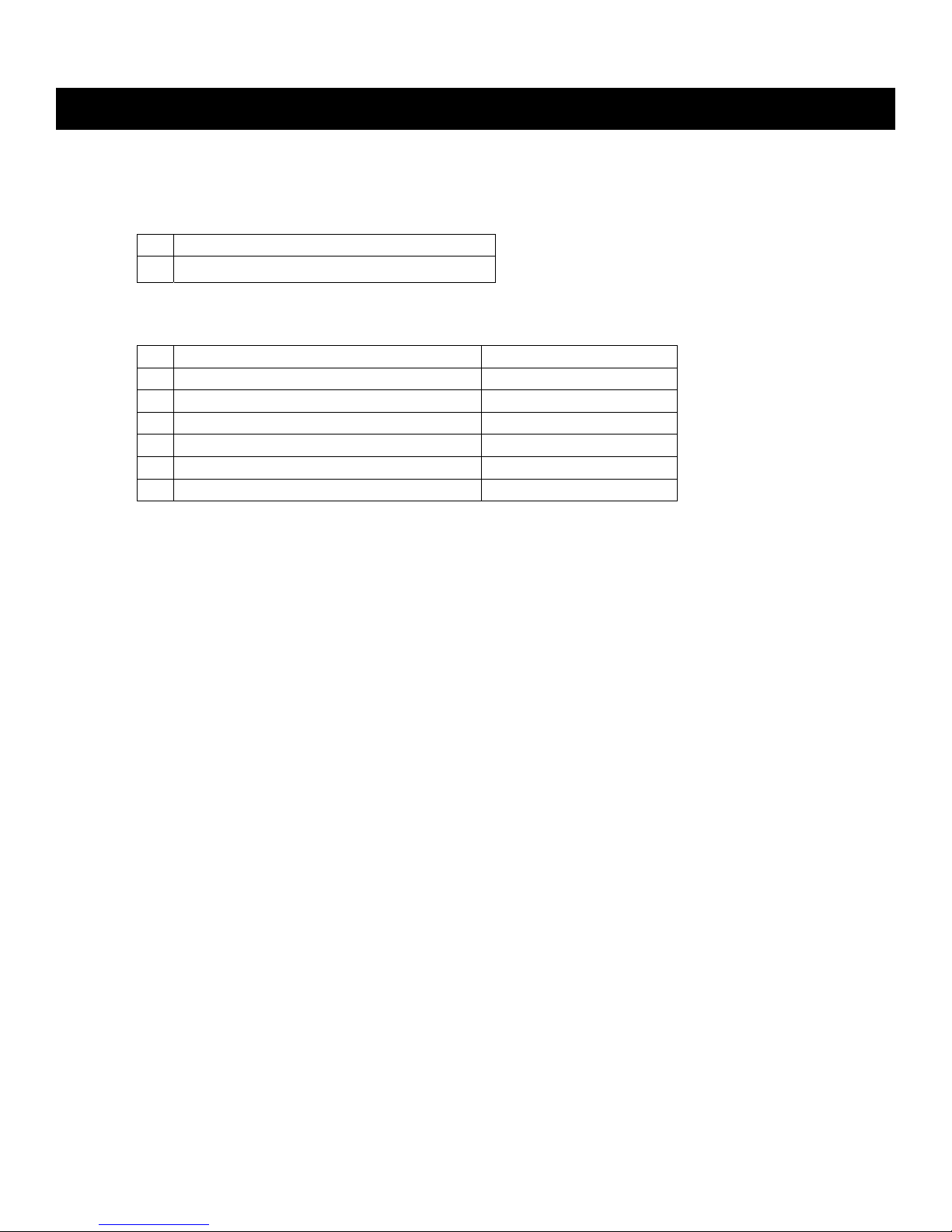
3 Disconnect link on ride height sensor to
prevent damage.
NOTE: Driver’s side only
4 Remove top nut and bolt for anti-roll bar
mount
6 Remove clevis bolt for lower shock
mount
5 of 28
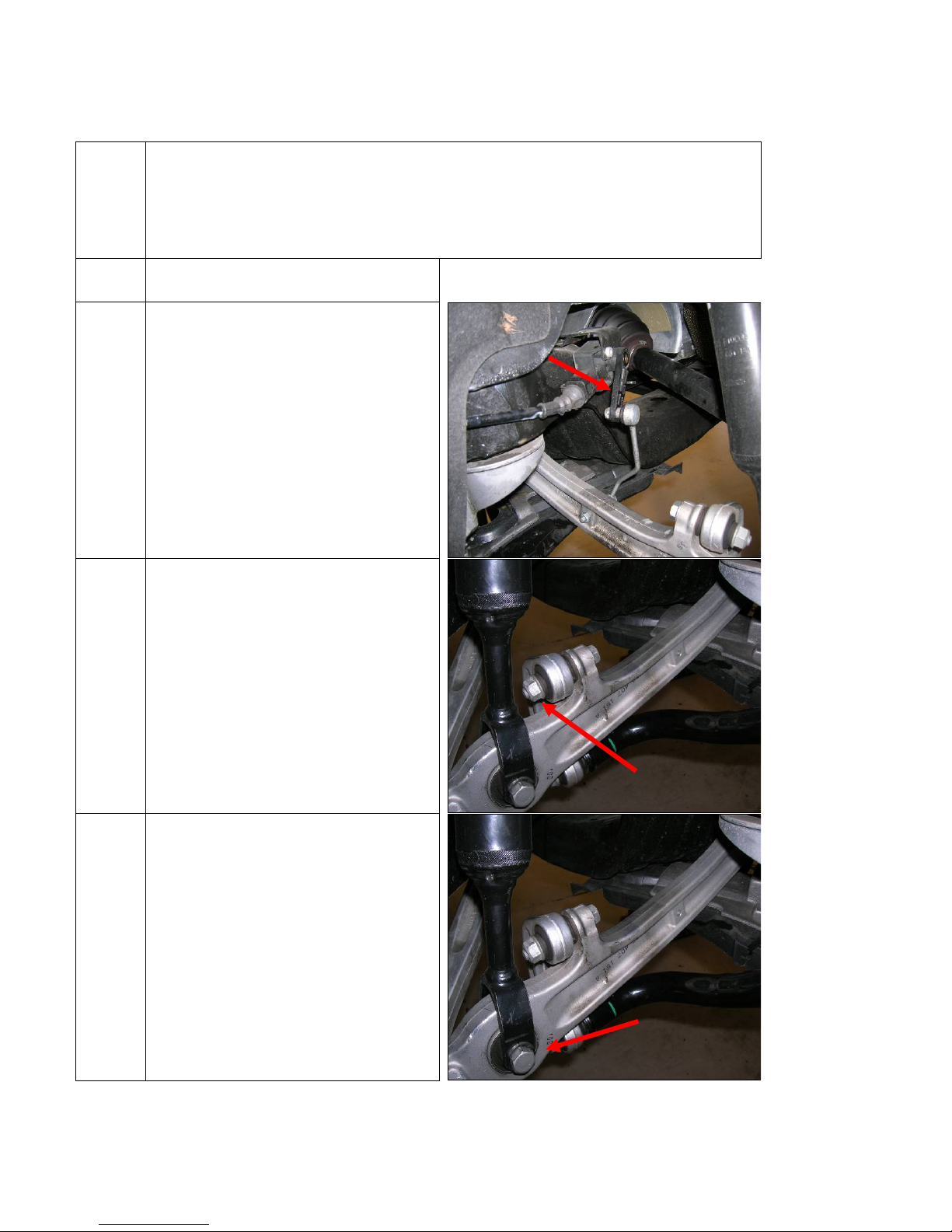
7 A) Remove top bolt for steering arm
B) Remove pinch bolt nut
NOTE: Do not allow bolt to back out or
turn. Remove nut, then remove bolt.
Pull down gently on steering arm thus
removing from upright
8 Remove the Upper Front Control Arm
nut and bolt.
Carefully pull up on control arms, thus
removing from upright
NOTE: The slits in the upright must not
be widened using a chisel or similar
tool! This can cause the pinch arms to
crack. If the control arm pins are stuck
in the housing, tap lightly with a rubber
mallet on the bottom of the control
arms.
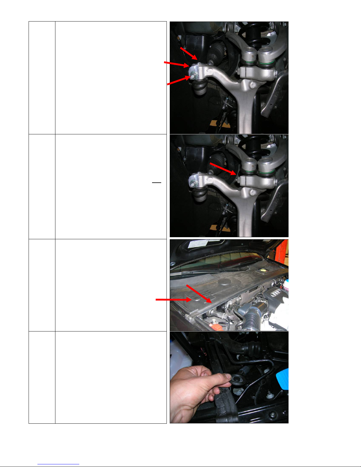
9 Peel back on rubber seal and remove
Now remove plastic cover to reveal
control arm girdle bolts
10 Remove bolts caps.
NOTE: These are easily removed with
long nose pliers
6 of 28
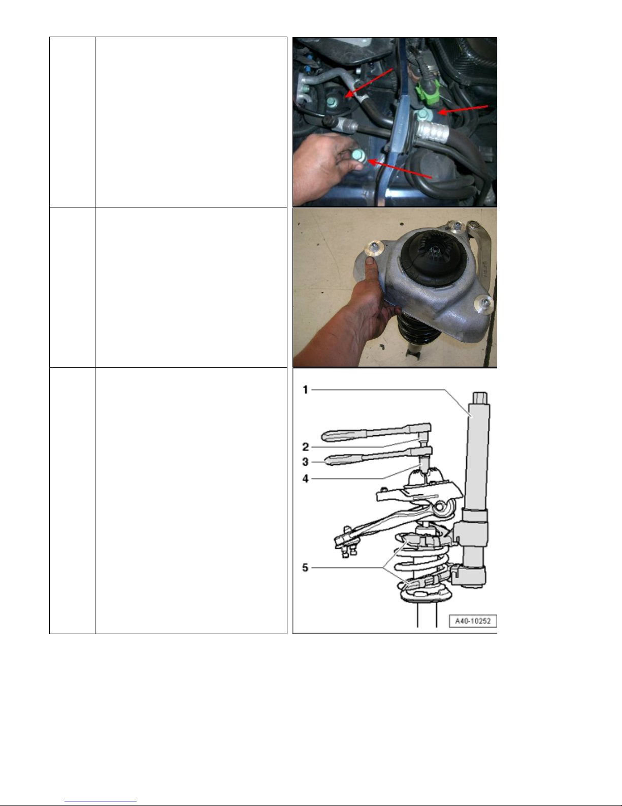
11 NOTE: 2 persons preferred
Person 1: Hold up damper assembly
from underneath car
Person 2: Remove 3 mounting bolts.
Alternate evenly between all 3
12 Carefully remove entire assembly.
13 Use an adequate spring compressor to
compress spring on shock assembly.
NOTE: Orientation of rubber mounts
and corresponding washers upon
removal of control arm girdle
7 of 28
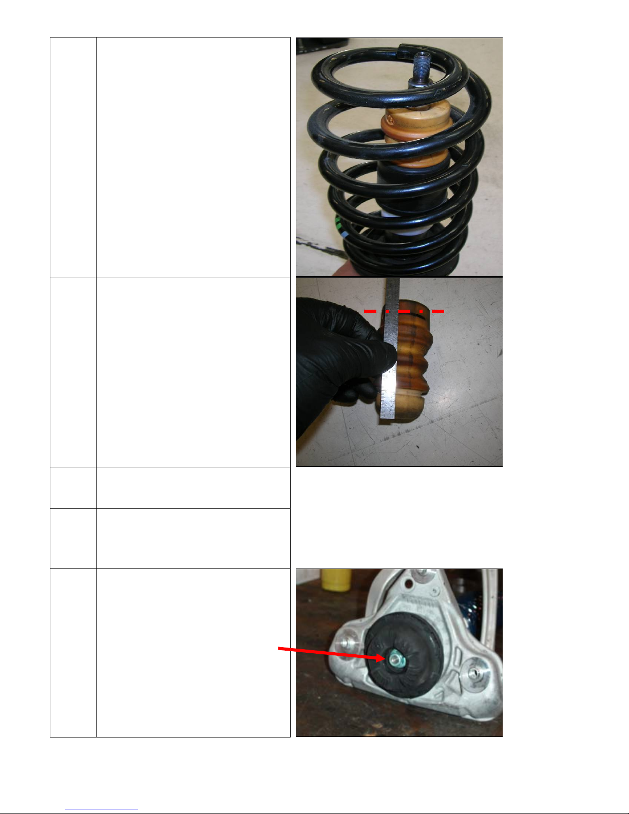
14 Image after removal of control arm
girdle.
Remove OEM spring and bumpstop
15 Accurately cut top of bump stop so final
length below dashed line is: 3 1/8 ”
16
17 NOTE: Rotate lower rubber spring
18 Re-install control arm girdle.
Install front lowering spring and
modified bumpstop
mount so spring registers properly on
both upper and lower rubber mounts
NOTE: DO NOT grab damper shaft with
any tools while tightening the nylock
nut.
Reinstall using same tool as was used
during removal
8 of 28
Installation
1 Installation is the opposite of removal.
When installing control arms and
steering arm , please note:
A) Slide steering arm into place, and
tighten the pinch bolt
B) If pinch bolt doesn’t go through,
move arm vertically while gently
pushing on bolt.
C) Apply blue LOCTITE on threads for
steering arm bolt, then tighten.
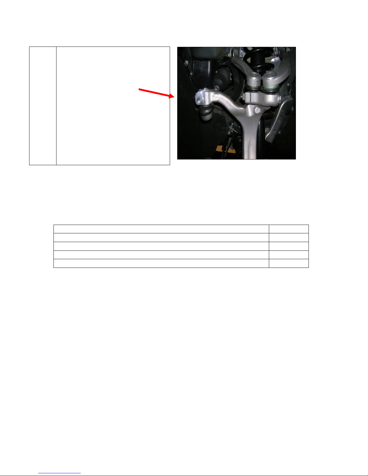
Rear Removal and Installation
Perform installation of rear ARB at the same time
*When performing complete Sig.Series package, removing OEM exhaust prior to ARB
highly recommended*
Torque Values
ARB Mounting Bracket Bolts, 10mm Triple Square 29 N m
Lower Drop Link Bolts 54 N m
Upper Drop Link Bolts 54 N m
Chassis Cross Brace Bolts 54 N m
Exhaust Muffler Hanger Nuts 20 N m
9 of 28
 Loading...