

Page 1

audi :: Audi S6 Wagon L5-2226cc 2.22L DOHC
Turbo (AAN) (1995)
Page 2

> Relays and Modules > Relays and Modules - Accessories and Optional Equipment > Audio Control Relay > Component Information > Locations
Audio Control Relay: Locations
Auxiliary Relay Panel I
Auxiliary Relay Panel I
Relay Location
1 - Open
2 - Coolant FC (Fan Control) Relay, J26
3 - Third Speed Coolant FC (Fan Control) Relay, J135
4 - Fog Light Relay, J5
5 - Open
6 - Relay for Power Sunroof Lock, J356
7 - Daytime Running Lights Relay (Switch-On), J90 (Canada Only)
8 - Selector Lever Light relay, J307
9 - A/C Clutch Relay, J44
10 - A/C Control Module, J153
11 - Rear Window Wiper/Washer Relay, J225
12 - Open
13 - Speaker Power Supply Relay, J225
14 - Lamp Control Module, J124
15 - Lamp Control Module, J124
16 - Servotronic Control Module, J236
17 - Open
Fuse Location
A1 - Automatic Window Closing Circuit Breaker, S99
A2 - Power Window Circuit Breaker, S43
A3 - Central Locking System Fuse, S52
A4 - Radio Fuse, S84
A5 - Door Lock Heating Element Fuse, S86
B1 - Memory Seat Adjusting Circuit Breaker, S44
Page 3

B2 - Power Seat Circuit Breaker, S80
B3 - Heated Seat Fuse, S79
B4 - Open
B4 - Sunroof Circuit Breaker, S83
Data Line Connector (DLC)
C1 - Black - B + (Battery Positive Voltage) and Ground (GND)
C2 - White - Rapid Data Transfer
C3 - Blue - Blink Code Output
Diagnostic Connector Terminals
K - DLC (Data Link Connector) - Rapid data Link Transfer
L - DLC (Data Link Connector) - ECM (Engine Control Module)
Page 4

> Relays and Modules > Relays and Modules - Body and Frame > Power Door Lock Control Module > Component Information > Testing and Inspection
Power Door Lock Control Module: Testing and Inspection
1 - Central locking/alarm system/interior light delay control module -V94-2 - 12-point connector3 - 6-point connector, voltage supply (B+)4 - 16-point connector5 - Not connected6 - Vacuum hose
Page 5

Page 6

> Relays and Modules > Relays and Modules - Body and Frame > Power Mirror Control Module > Component Information > Locations
Power Mirror Control Module: Locations
Component locations, under rear seat
Component Locations, Under Rear Seat
1. Central locking/alarm system/interior light delay control module -V94-2. Battery -A-3. Mirror memory control module -J267-4. ABS acceleration switch -F113- 5. Airbag energy reserve -J177-6. ABS control module (w/EDL) -J104-7. Airbag voltage transformer -N96-
Page 7

Page 8

> Relays and Modules > Relays and Modules - Brakes and Traction Control > ABS Control Module <--> [Electronic Brake Control Module] > Component Information > Service and Repair
ABS Control Module: Service and Repair
The electronic control unit is located beneath the lefthand side of the rear seat.
1. Turn ignition switch to the Off position.
2. Remove rear seat.
3. Remove spring retaining electrical connector, then disconnect electrical connector.
4. Remove screws securing control unit.
5. Reverse procedure to install.
Page 9

Page 10

> Relays and Modules > Relays and Modules - Cooling System > Radiator Cooling Fan Control Module > Component Information > Diagrams > Diagram Information and Instructions > Understanding Track Style Wiring
Diagrams, Important Stuff !
Radiator Cooling Fan Control Module: Diagram Information and InstructionsUnderstanding Track Style Wiring Diagrams, Important Stuff !
What the heck is a "Track Diagram"?
Engine Specific - Main Wiring Diagrams
Engine Specific - Main Wiring Diagrams
Optional/Common Equipment
Audi's "Current Flow Diagrams" or track scheme of wiring diagrams is truly one very large view of the electrical systems and componentsincorporated on a particular vehicle. The "" or standard equipment diagrams, i.e. Tracks 1 - 308, willcontain all components starting from the battery and moving to the brake lights [optional equipment excluded]. However, since it would be physicallyimpossible to view all the tracks on one display or page, they have broken this large system of "" intosmaller Component related divisions. For example, "Battery, Starter, Generator and Voltage Regulator" may be found on "Tracks 1 - 14", and "BrakeLights and Backup Lights" found on "Tracks 293 - 308". diagrams are added for systems or components which Audidoes not consider standard equipment for a particular model, i.e. Air Conditioning, Traction Control, Central locking and Power Sunroof, to mention afew. Optional equipment will vary from model to model.
.For example, while "Tracks 1 - 14" under "Engine Specific - Main Wiring Diagrams" may be used for "Battery, Starter, Generator and VoltageRegulator", the same term "Tracks 1 - 14" can also be used for the optional equipment diagrams "Cruise Control" and "Heated Seats", since theyrepresent three separate diagram schemes.
Page 11

> Relays and Modules > Relays and Modules - Cooling System > Radiator Cooling Fan Control Module > Component Information > Diagrams > Diagram Information and
Instructions > Understanding Track Style Wiring Diagrams, Important Stuff ! > Page 24
S6 Wagon L5-2226cc 2.22L DOHC Turbo (AAN) (1995)
Page 12

Page 13
> Relays and Modules > Relays and Modules - Cooling System > Radiator Cooling Fan Control Module > Component Information > Diagrams > Diagram Information and
Instructions > Understanding Track Style Wiring Diagrams, Important Stuff ! > Page 25
S6 Wagon L5-2226cc 2.22L DOHC Turbo (AAN) (1995)
Page 14

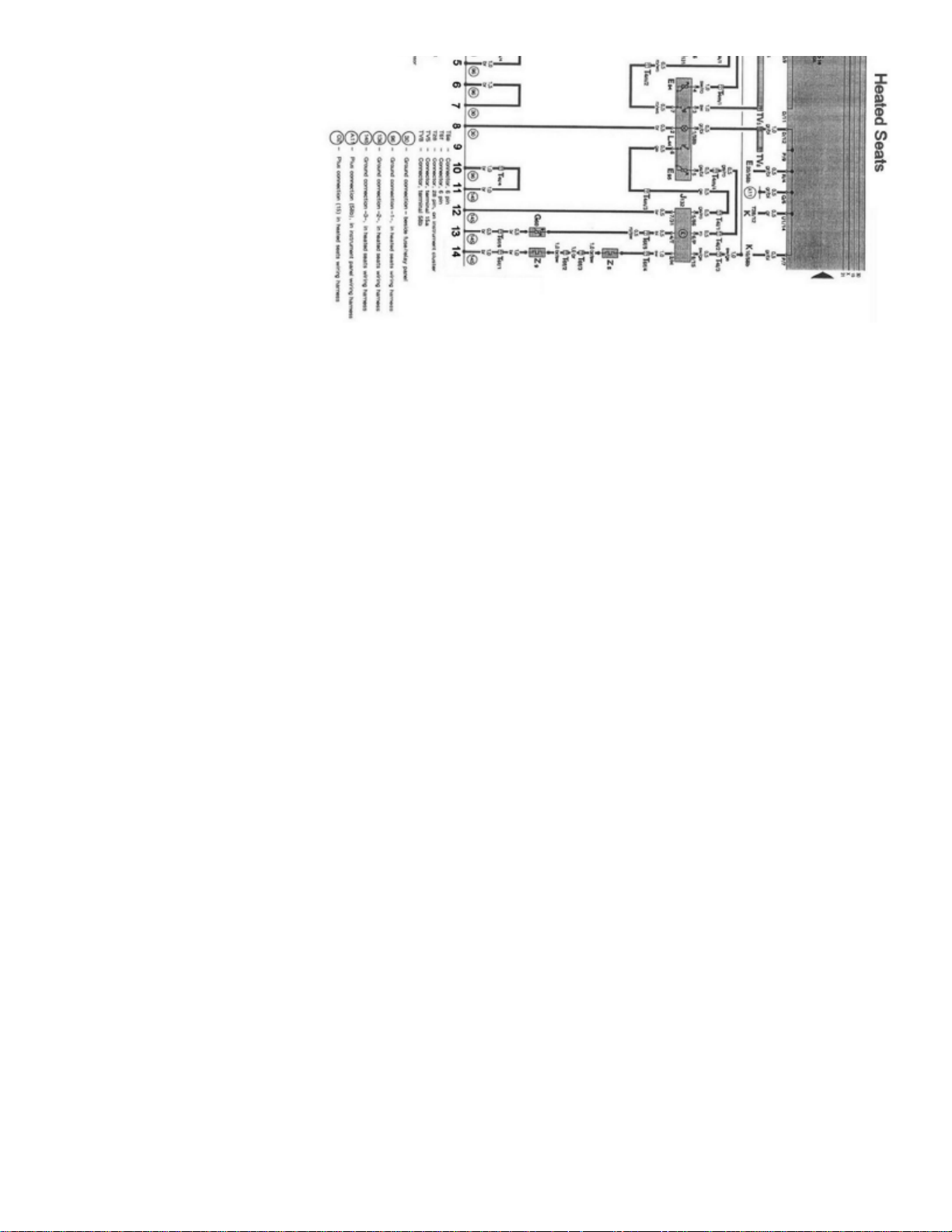
Tracks 1 - 14 from the Main DiagramsTracks 1 - 14 from the Cruise Control DiagramsTracks 1 - 14 from the Heated Seats Diagrams
Don't be confused; this is not a mistake! Furthermore, track numbering schemes do not necessarily have to be consecutive, and there may appearto be missing tracks. Again this is not a mistake.
Additional Caution should be taken when using Optional/Common Equipment wiring diagrams
. Do not try to intermix the "Engine Specific- Main Wiring Diagrams" and Optional/Common Equipment wiring diagrams. The optional equipment diagrams are self contained, complete,power to ground diagrams. Components such as the "Fresh Air Blower Motor" found in the Heating and Air Conditioning diagrams are not wiredthe same way as the "Fresh Air Blower Motor" found in the "Engine Specific - Main Wiring Diagrams", which is used for models without AirConditioning.
"Current Flow Diagrams" or "Track" style wiring diagrams show the powerflow through all wires, connectors, switches and motors beginning at thetop of the page, usually the fuse/relay box, down the page to "ground" at the bottom. If a particular Current Track does not provide all of the "Powerto Ground" information about a system or component, continuations and splices, etc. will be shown. See: Diagrams/Electrical Diagrams/EngineSpecific - Main Wiring Diagrams/Track Diagrams
Page 15

> Relays and Modules > Relays and Modules - Cooling System > Radiator Cooling Fan Control Module > Component Information > Diagrams > Diagram Information and
Instructions > Understanding Track Style Wiring Diagrams, Important Stuff ! > Page 26
S6 Wagon L5-2226cc 2.22L DOHC Turbo (AAN) (1995)
Things you need to know how to use!
Page 16

- How to Find the Correct Wiring Diagram- How to Read Displayed Page of Wiring Diagram- Wiring Diagram Circuit Identification- Symbols Used In Wiring Diagrams- Wire Color Code Identification- Wire Size Conversion
Page 17

Page 18

> Relays and Modules > Relays and Modules - Cooling System > Radiator Cooling Fan Control Module > Component Information > Diagrams > Diagram Information and Instructions > Understanding Track Style Wiring
Diagrams, Important Stuff ! > Page 27
Radiator Cooling Fan Control Module: Diagram Information and InstructionsHow to Read Displayed Page of Wiring Diagram, Important Stuff !
Page 19

> Relays and Modules > Relays and Modules - Cooling System > Radiator Cooling Fan Control Module > Component Information > Diagrams > Diagram Information and
Instructions > Understanding Track Style Wiring Diagrams, Important Stuff ! > Page 28
S6 Wagon L5-2226cc 2.22L DOHC Turbo (AAN) (1995)
Wiring Diagram Layout
How To Read Wiring Diagrams
Page 20

1 -
Indicates wiring circuit is continued on the previous and/or next page.Arrow
2 -
Page 21

> Relays and Modules > Relays and Modules - Cooling System > Radiator Cooling Fan Control Module > Component Information > Diagrams > Diagram Information and
Instructions > Understanding Track Style Wiring Diagrams, Important Stuff ! > Page 29
S6 Wagon L5-2226cc 2.22L DOHC Turbo (AAN) (1995)
For example: = Fuse number , , in fusel relay panel.Fuse designation S15 15 10 amps
3 - Test points on fuse/relay panel
4 -
Numbers in black circles may be found in a regular wiring diagram or in a wiring diagram included with troubleshooting.Test points used during troubleshooting.
Page 22

5 -
Wire cross-section size (in mm2) and wire colors
See chart above for wire size conversion to American Wire Gauge (AWG). Wire color abbreviations are explained in color code chart on eachpage of the wiring diagram.
6 -
Use legend at bottom of page to identify the component code.Component designation (code)
7 -
Internal connections (thin lines)
These connections are not always wires. Internal connections are current carrying and are listed to allow tracing of current flow insidecomponents and wiring hamesses.
8 -
Locations of ground connections are indicated in the legend.Wire harness ground connection
9 -
Shows the individual terminals in a multi-point connector. Example: 4/30Relay/control module connectors on fuse/relay panel
= contact at location on relay panel or relay carrier4 4 [3]
= terminal on relay/control module30 30 (B+)
10 -
Indicates relay location on fuse/relay panel.Relay location number
11 -
Shows wiring of multi-point or single connectors on fuse/relay panel.Fuse/relay panel connectors
Example: = multi-point connector , terminal G1/10 G1 10
12 -
Designation which appears on actual component and/or terminal number of a multi-point connector.Terminal designation
13 -
Number in frame indicates current track where wire is continued.Wire continuation (current track number)
14 -
Letters indicate where connection continues on the previous and/or next page.Continuation of internal connections
15 - Component symbols (see page IV and V)
16 -
Locations of wire connections are indicated in the legend.Wiring harness wire connection
17 -
Indicates component is continued on the previous and/or next page.Arrow
18 - Circuit Identification (Fuse/Relay Panel)
1
- Ignition coil/ignition distributor low voltage (typically used as an Engine Speed (RPM) signal for the tachometer)
15
- Switched Battery Positive Voltage (B+) from ignition/starter switch
30
- Battery Positive Voltage (B+), hot at all times
Page 23

31
- Ground (GND)
50
- Starter control; switched B+ from ignition/starter switch
56
- Switched headlight B+ from light switch
58
- Switched parking light, taillight. illumination B+ from light switch
S (SU)
- Key In ignition circuit: switched B+ from ignition/starter switchX
- Load reduction circuit; switched B+ from load reduction relay
Page 24

> Relays and Modules > Relays and Modules - Cooling System > Radiator Cooling Fan Control Module > Component Information > Diagrams > Diagram Information and Instructions > Understanding Track Style Wiring
Diagrams, Important Stuff ! > Page 30
Radiator Cooling Fan Control Module: Diagram Information and InstructionsSymbols Used In Wiring Diagrams
Symbols Used in Wiring Diagrams
Page 25

> Relays and Modules > Relays and Modules - Cooling System > Radiator Cooling Fan Control Module > Component Information > Diagrams > Diagram Information and
Instructions > Understanding Track Style Wiring Diagrams, Important Stuff ! > Page 31
S6 Wagon L5-2226cc 2.22L DOHC Turbo (AAN) (1995)
Symbols (Part 1 Of 2)
Page 26

Page 27

Symbols (Part 2 Of 2)
Page 28

> Relays and Modules > Relays and Modules - Cooling System > Radiator Cooling Fan Control Module > Component Information > Diagrams > Diagram Information and Instructions > Understanding Track Style Wiring
Diagrams, Important Stuff ! > Page 32
Radiator Cooling Fan Control Module: Diagram Information and InstructionsWiring Diagram Circuit Identification
Wiring Diagram Terminal (circuit) Identification
Several wiring circuits in the vehicle's electrical system are identified with a number or letter designation. These circuits are identified the same inall wiring diagrams and are most commonly shown near the top of each page in the fuse/relay panel portion of the wiring diagram. The circuitdesignations may also be used to identify switch connector terminals (switch circuits). Following are the most common numbered/lettered circuits:
:Terminal (circuit)
1
- Ignition coil/ignition distributor low voltage (typically used as an Engine Speed (RPM) signal for the tachometer)
15
- Switched Battery Positive Voltage (B+) from ignition/starter switch
30
- Battery Positive Voltage (B +), hot at all times
31
- Ground (GND)
50
- Starter control; switched B+ from ignition/starter switch
56
- Switched headlight B+ from light switch
58
- Switched parking light, taillight. illumination B+ from light switch
- Key In ignition circuit: switched B+ from ignition/starter switchS (SU)
X
- Load reduction circuit; switched B+ from load reduction relay
Page 29

Page 30

> Relays and Modules > Relays and Modules - Cooling System > Radiator Cooling Fan Control Module > Component Information > Diagrams > Diagram Information and Instructions > Understanding Track Style Wiring
Diagrams, Important Stuff ! > Page 33
Radiator Cooling Fan Control Module: Diagram Information and InstructionsWire Color Code Identification
Wire Color Code Identification
WS
- White
SW
- Black
RO
- Red
BR
- Brown
GN
- Green
BL
- Blue
GR
- Gray
LI
- Violet
GE
- Yellow
OR
- Orange
Combined codes indicate a multi-colored wire.Example: The code R/G indicates a red wire with a green tracer strip.
Page 31

Page 32

> Relays and Modules > Relays and Modules - Cooling System > Radiator Cooling Fan Control Module > Component Information > Diagrams > Diagram Information and Instructions > Understanding Track Style Wiring
Diagrams, Important Stuff ! > Page 34
Radiator Cooling Fan Control Module: Diagram Information and InstructionsWire Size Conversion
Wire Size Conversion Chart
Wire cross-section size (in mm2) and wire colorsSee chart above for wire size conversion to American Wire Gauge (AWG). Wire color abbreviations are explained in color code chart on eachpage of the wiring diagram.
Page 33

Page 34

> Relays and Modules > Relays and Modules - Cooling System > Radiator Cooling Fan Control Module > Component Information > Diagrams > Diagnostic Aids > Troubleshooting Basics > Basic Electricity
Radiator Cooling Fan Control Module: Diagnostic AidsBasic Electricity
Electricity
Electricity is defined by three basic elements: Voltage, Current and Resistance.
Voltage
Voltage is a measure of electromotive force, sometimes referred to as electrical "pressure". It can be described as the difference in potential(potential for the flow of electricity) between any two points in a circuit.
12 Volts
A typical automobile battery, for example, has a difference in potential of about between the positive (+) terminal and the negative (-)terminal.
The basic units of electrical potential are (V). Very low Voltages are expressed as (mV).Volts millivolts
= ; = 1 V 1000 mV 1 mV 0.001 V
Current
Current is the term describing the flow of electricity through a conductor. In a complete circuit, potential (Voltage) will cause current to flow frompositive (+) to negative (-).
The basic units of current flow are or (A). Small amounts of current flow are often measured in (mA).amperes amps milliamps
= ; = 1 A 1000 mA 1 mA 0.001 A
Resistance
Resistance resists or opposes the flow of electricity. Conductors are made from materials of low resistance that allow electricity to flow easily.Insulators are materials of very high resistance that inhibit the low of electricity.
The basic unit of resistance is the . High resistance values are often expressed as .Ohm Kilo ohms (K ohm)
= 1K ohm 1000 ohm
Resistance vs. Current Flow
1 Volt 1 am
The basic rule of electricity (Ohm's Law) states that one unit of force () is required for one unit of current () to flow against one unit ofresistance (). From Ohm's Law, we also know that:1 Ohm
Voltage = Current x Resistance
When Voltage is approximately constant, as in an automobile electrical system, current and resistance affect each other. As resistance increases,there will be less current flow. And lower resistance will permit higher current flow.
Higher resistance = lower current flow
Example: Corrosion on a headlight connector (higher resistance) causes the light to be dim (lower current flow).
Lower resistance = higher current flow
Example: A damaged wire shorted to ground (lower resistance) overloads circuit capacity (higher current flow) and blows a fuse. (GND)
Definition of a Circuit
Page 35

> Relays and Modules > Relays and Modules - Cooling System > Radiator Cooling Fan Control Module > Component Information > Diagrams > Diagnostic Aids >
Troubleshooting Basics > Basic Electricity > Page 38
S6 Wagon L5-2226cc 2.22L DOHC Turbo (AAN) (1995)
Page 36

A Complete Circuit
Four things are required for current to flow in any electrical circuit, and for that circuit, and for that circuit to function as intended:-
Power Source (Voltage)
- Conductors (wires, printed circuits, etc.)
- Load or Consumer (a user of electrical power)
- Complete Circuit (a connection to ground)
Open Circuits
An open circuit is an incomplete circuit. An open circuit occurs when some kind of malfunction interrupts the circuit path and prevents currentflow. Some common causes of open circuits are:-
Broken wire
- Loose or disconnected connector
- Loose or damaged connector terminal
- Corrosion
- Malfunctioning fuse or component
Test for an open circuit by checking continuity using an Ohmmeter (multimeter), or by checking for Voltage at various points of the circuit using atest light or Voltmeter (multimeter). See Checking Wiring and Components.
Short Circuits
A short circuit is an unintended complete circuit. A short circuit occurs when some kind of malfunction causes current flow to follow the wrongpath.
Page 37

A short circuit to ground (GND) (grounded circuit) may prevent Voltage from reaching a component. If Voltage is shorted directly to ground(GND), bypassing any load, the unrestricted current flow will damage fuses wires or components. Some common causes of short circuits are:-Damaged wire or wiring harness- Malfunctioning insulation
- Internally damaged component
- Incorrect connection
Test for a short circuit to ground (GND) using a multimeter or a test light to indicate circuit malfunctions and abnormal current flow paths. SeeChecking for Short Circuit to Ground (GND).
Page 38

> Relays and Modules > Relays and Modules - Cooling System > Radiator Cooling Fan Control Module > Component Information > Diagrams > Diagnostic Aids > Troubleshooting Basics > Basic Electricity > Page 39
Radiator Cooling Fan Control Module: Diagnostic AidsChecking For Voltage
Voltage
Checking for Voltage confirms that the circuit is uninterrupted between the Voltage source and the test point.
Page 39

> Relays and Modules > Relays and Modules - Cooling System > Radiator Cooling Fan Control Module > Component Information > Diagrams > Diagnostic Aids >
Troubleshooting Basics > Basic Electricity > Page 40
S6 Wagon L5-2226cc 2.22L DOHC Turbo (AAN) (1995)
Testing For Voltage
This example illustrates troubleshooting the high-speed circuit for the radiator cooling fan.
Voltage:
If the test light or multimeter indicates Voltage potential, then the circuit between the Voltage source and terminal 1 of the fan connector is OK.
NO Voltage:
Page 40

Power is not reaching the fan connector. The fan is probably OK. Look for a malfunction somewhere between the Voltage source and the fanconnector. (Example: Check for Voltage reaching terminal E87La of the fuse/relay panel)
CAUTION:
Direct contact with meter probes at the connector terminals can easily damage the small contacts, causing poor connections and risking futureintermittent malfunctions.Special Tools include adapters for making test connections safely and preventing connector damage. See Tools and Equipment.
Page 41

Page 42

> Relays and Modules > Relays and Modules - Cooling System > Radiator Cooling Fan Control Module > Component Information > Diagrams > Diagnostic Aids > Troubleshooting Basics > Basic Electricity > Page 41
Radiator Cooling Fan Control Module: Diagnostic AidsChecking Ground Connection
Ground Connection
Checking ground (GND) connections as shown confirms that the circuit is complete that the necessary path to ground (GND) is uninterrupted andcurrent can flow in the circuit. The examples illustrate two methods of troubleshooting a high-speed circuit for the radiator cooling fan. Testing with an ohmmeter and testing with atest light or voltmeter.
Testing With An LED Test Light Or Voltmeter (Multimeter)
Page 43

> Relays and Modules > Relays and Modules - Cooling System > Radiator Cooling Fan Control Module > Component Information > Diagrams > Diagnostic Aids >
Troubleshooting Basics > Basic Electricity > Page 42
S6 Wagon L5-2226cc 2.22L DOHC Turbo (AAN) (1995)
Page 44

Page 45

> Relays and Modules > Relays and Modules - Cooling System > Radiator Cooling Fan Control Module > Component Information > Diagrams > Diagnostic Aids >
Troubleshooting Basics > Basic Electricity > Page 43
S6 Wagon L5-2226cc 2.22L DOHC Turbo (AAN) (1995)
Testing For Ground Connection
Voltage:
If the test light or multimeter indicates Voltage, then there is potential for current flow between the known Voltage source and ground (GND) atthe test point. The ground (GND) side of the circuit, between terminal 3 of the fan connector and battery negative (-), is OK.
NO Voltage:
The test point is not providing a path that completes the circuit to ground (GND). The fan is probably OK. Look for a malfunction somewhere inthe wiring between the fan connector and chassis ground (GND). Also check the mechanical ground connection at the chassis (body).
Page 46

Testing With An Ohmmeter (Multimeter):
Page 47

> Relays and Modules > Relays and Modules - Cooling System > Radiator Cooling Fan Control Module > Component Information > Diagrams > Diagnostic Aids >
Troubleshooting Basics > Basic Electricity > Page 44
S6 Wagon L5-2226cc 2.22L DOHC Turbo (AAN) (1995)
Testing For Ground Connection
Continuity (approximately 0 Ohm):
Little or no resistance indicates that there is a continuous conductive path between the two test points - the circuit's ground (GND) path betweenterminal 3 and battery negative (-) is OK.
No Continuity:
Page 48

There is resistance to current flow in the ground (GND) side of the circuit. The fan is probably OK. Look for a malfunction somewhere in thewiring between the fan connector and chassis ground (GND). Also check the mechanical ground (GND) connection at the chassis (body).
CAUTION:
Direct contact with meter probes at the connector terminals can easily damage the small contacts, causing poor connections and risking futureintermittent malfunctions.Special Tools include adapters for making test connections safely and preventing connector damage. See Tools and Equipment.
Page 49

Page 50

> Relays and Modules > Relays and Modules - Cooling System > Radiator Cooling Fan Control Module > Component Information > Diagrams > Diagnostic Aids > Troubleshooting Basics > Basic Electricity > Page 45
Radiator Cooling Fan Control Module: Diagnostic AidsChecking Wiring and Components
Checking Resistance Or Continuity
Checking a portion of the wiring harness or a component as shown indicates whether or not there is a continuous conductive path - whether currentcan flow between the two test points. The example illustrates troubleshooting the Close Throttle Position switch and the Wide Open ThrottlePosition switch in the fuel injection system.
CAUTION:
Resistance measurements and continuity checks must always be made with all power to the circuit or component switched OFF. When testingcontinuity in a circuit that is always powered (fuse/relay panel "30" circuit for example) disconnect the battery before testing. Always use a digital (low current) meter. An ohmmeter, or the Ohms scale of a multimeter, measures resistance by passing a small amount ofcurrent through the circuit or component being checked. Improper testing may damage sensitive electronic components. Direct contact with meter probes at the connector terminals can easily damage the small contacts, causing poor connections and risking futureintermittent malfunctions.Special Tools include adapters for making test connections safely and preventing connector damage. See Tools and Equipment.
Example 1: Checking A Closed Throttle Position Switch
Page 51

> Relays and Modules > Relays and Modules - Cooling System > Radiator Cooling Fan Control Module > Component Information > Diagrams > Diagnostic Aids >
Troubleshooting Basics > Basic Electricity > Page 46
S6 Wagon L5-2226cc 2.22L DOHC Turbo (AAN) (1995)
Testing For Resistance Or Continuity
Page 52

Continuity (approximately 0 ohm):
Little or no resistance indicates that there is a continuous conductive path between the two test points. As shown, this is correct for the normallyClosed Throttle Position switch in the Closed Throttle Position (switch not actuated). Also check that the switch opens (no continuity) whenactuated by the throttle.
No Continuity:
There is resistance to current flow through the switch. In the example, this indicates that the normally Closed Throttle Position switch or the wiresbetween it and the connector (t3) are malfunctioning.
Example 2: Checking A Wide Open Throttle Position Switch
Testing For Resistance Or Continuity
Continuity (approximately 0 ohm):
Little or no resistance indicates that there is a continuous conductive path between the two test points. In the example, this indicates that thenormally Wide Open Throttle Position switch is malfunctioning.
No Continuity:
There is no connection-an open circuit. As shown, this is correct for the normally Wide Open Throttle Position switch. Also check that the switchcloses, completing the circuit, when actuated by the Wide Open Throttle Position switch.
Page 53

Page 54

> Relays and Modules > Relays and Modules - Cooling System > Radiator Cooling Fan Control Module > Component Information > Diagrams > Diagnostic Aids > Troubleshooting Basics > Basic Electricity > Page 47
Radiator Cooling Fan Control Module: Diagnostic AidsChecking For Short Circuit to Ground
Short Circuits
(GND)
Checking the circuit as shown will detect circuit malfunctions that are providing an unintended current flow path to ground . Covered here aretwo methods of troubleshooting a short circuit to ground (GND). Testing with an ohmmeter and testing with a test light or voltmeter.
CAUTION:
Always use a digital (low current) meter. An ohmmeter, or the Ohms scale of a multimeter, measures resistance by passing a small amount of currentthrough the circuit or component being checked. Improper testing may damage sensitive electronic components.Direct contact with meter probes at the connector terminals can easily damage the small contacts, causing poor connections and risking futureintermittent malfunctions. Special Tools include adapters for making test connections safely and preventing connector damage. See Tools andEquipment.
Testing With An Ohmmeter (Multimeter):
Page 55

> Relays and Modules > Relays and Modules - Cooling System > Radiator Cooling Fan Control Module > Component Information > Diagrams > Diagnostic Aids >
Troubleshooting Basics > Basic Electricity > Page 48
S6 Wagon L5-2226cc 2.22L DOHC Turbo (AAN) (1995)
Testing For Short Circuit To Ground
The example used here is a short that is causing a blown fuse in the circuit powering the license plate lights and the glove compartment light.
Step 1 - Remove the fuse
Page 56

Step 2 - Disconnect the load (powered components) to eliminate the circuit's normal path to ground (GND)Step 3 - Connect the Ohmmeter as illustrated
Continuity (approximately 0 ohm):
Little or no resistance indicates that there is a continuous conductive path between the isolated circuit and ground (GND), even though all thecircuit's normal ground (GND) paths are eliminated. There is a short - an unintentional connection to ground (GND) - somewhere in the circuit.
No Continuity:
The circuit's normal ground (GND) paths have been disconnected, and there is no other connection between the isolated circuit and ground (GND)- no short has been detected.
Testing With An LED Test Light Or Voltmeter (Multimeter)
Page 57

> Relays and Modules > Relays and Modules - Cooling System > Radiator Cooling Fan Control Module > Component Information > Diagrams > Diagnostic Aids >
Troubleshooting Basics > Basic Electricity > Page 49
S6 Wagon L5-2226cc 2.22L DOHC Turbo (AAN) (1995)
Testing For Short Circuit To Ground
The example used here is a short that is causing a blown fuse in the circuit powering the license plate lights and the glove compartment light.
Page 58

Step 1 - Remove the fuseStep 2 - Disconnect the load (powered components) to eliminate the circuit's normal path to ground (GND)Step 3 - Connect the test light or voltmeter as illustrated
Voltage:
If the test light or multimeter indicates Voltage, then there is a complete circuit - a connection to ground (GND) even though all the circuit'sNormal ground (GND) paths are eliminated. There is a short - an unintentional connection to ground (GND) - somewhere in the circuit.
NO Voltage:
There is not a complete circuit. The circuit's normal ground (GND) paths have been disconnected, and there is no other connection between theisolated circuit and ground (GND) - no short has been detected.
Page 59

Page 60

> Relays and Modules > Relays and Modules - Cooling System > Radiator Cooling Fan Control Module > Component Information > Diagrams > Diagnostic Aids > Troubleshooting Basics > Basic Electricity > Page 50
Radiator Cooling Fan Control Module: Diagnostic AidsChecking For Voltage Drop
Voltage Drop Test
Checking Voltage drop across connections or components as shown will indicate whether there is abnormal resistance creating an additional loadin the circuit - consuming power and dropping the Voltage available to other parts of the circuit.
Voltage drop measurements can only be made when the circuit is powered and there is normal current flow.NOTE:
Page 61
> Relays and Modules > Relays and Modules - Cooling System > Radiator Cooling Fan Control Module > Component Information > Diagrams > Diagnostic Aids >
Troubleshooting Basics > Basic Electricity > Page 51
S6 Wagon L5-2226cc 2.22L DOHC Turbo (AAN) (1995)
Testing For Voltage Drop
The example illustrates troubleshooting the back-up light switch. The switch is in the circuit to switch power to the back-up lights ON and OFF.When Reverse gear is selected and the switch is closed, it should have very little resistance and not be a consumer.
If dirt or corrosion on the switch contacts creates resistance, some of the available battery Voltage goes into overcoming that resistance. LessVoltage is available to light the back-up lights, and they will not be as bright.
Page 62

An ohmmeter can measure resistance (or check continuity) only when the circuit is not powered, i.e. when there is almost no load.NOTE:
Low Voltage:
A low Voltage reading across the two switch contacts indicates almost no difference in potential. Resistance across the switch is low - most of thebattery Voltage is passing through the switch and is still available to power the lights.
High Voltage:
Any significant Voltage reading indicates a difference in potential across the switch contacts. Excessive resistance is loading the circuit, causing aVoltage Drop. Voltage is consumed overcoming the resistance of the switch, and less is left to power the lights.
Maximum allowable Voltage drops recommended by the Society of Automotive Engineers are:
0.0 Volt
0.1 Volt
0.1 Volt
0.2 Volt
for small wire connections for high-current connections (Example: fuel pump, headlights) for ground (GND) connections for high-current cables (Example: battery/starter cable) for switch or relay contacts0.3 Volt
Page 63

Page 64

> Relays and Modules > Relays and Modules - Cooling System > Radiator Cooling Fan Control Module > Component Information > Diagrams > Diagnostic Aids > Troubleshooting Basics > Page 52
Radiator Cooling Fan Control Module: Diagnostic AidsHandling Components and Connector
Harness Connectors
The harness connectors used throughout the vehicle are designed to positively lock into place.
Harness Connector
Typical wiring harness connector. Push on wire lock (arrow) and gently pull on connector to release.
To disconnect, pull only on the connector body. Never pull on the wires themselves.CAUTION:
Making Test Connections
Many electrical troubleshooting tests will require hooking up to wiring harness connectors, or socket connectors on electrical components. Testconnections made carelessly or without proper tools can easily damage the connectors, causing poor connections and future problems.
Alligator-clip Test Leads With Flat Connectors
To avoid connector damage, test connections to wiring harness connectors must be made using small, flat-blade terminals which will mate properlywith the connectors. The Special Tools recommended include special adapters which can be used to make test connections safely and preventconnector damage. See Tools and Equipment.All test connections to harness connectors should be made using the proper adapter or correct size flat connectors that will not deform the connectorcavities.
Wiring Harness Repairs
Page 65

> Relays and Modules > Relays and Modules - Cooling System > Radiator Cooling Fan Control Module > Component Information > Diagrams > Diagnostic Aids >
Troubleshooting Basics > Page 53
S6 Wagon L5-2226cc 2.22L DOHC Turbo (AAN) (1995)
Page 66

W-Type Crimp Connection
When repairing wiring harnesses, use only high-quality electrical connectors suitable for use with electronic components.
Wire Crimping Pliers, For Making W-Type Crimps
Page 67

> Relays and Modules > Relays and Modules - Cooling System > Radiator Cooling Fan Control Module > Component Information > Diagrams > Diagnostic Aids >
Troubleshooting Basics > Page 54
S6 Wagon L5-2226cc 2.22L DOHC Turbo (AAN) (1995)
Wire Crimping Pliers, Not Suitable For W-Type Crimps
Page 68

To make connections, use crimping pliers that make a "W"-type crimp. Only this type of crimp provides the necessary mechanical strength.Connector repair kits, connectors and the correct crimping pliers are available through your authorized dealer Parts Department.
Wiring Harness Repair Kit VAS 1978
Wire Harness Repair Kit, VAS 1978
Wiring Harness Repair Kit VAS 1978 was developed to simplify wiring harness repairs by using factory pre-crimped replacement wires thuselimination numerous repair kits and crimping fixtures. All of the tools and parts are conveniently located in one case and are easy to use. VAS 1978kit reduces the total repair steps needed to effect repair.
Page 69

Page 70

> Relays and Modules > Relays and Modules - Cooling System > Radiator Cooling Fan Control Module > Component Information > Diagrams > Diagnostic Aids > Tools and Equipment > LED Test Light
Radiator Cooling Fan Control Module: Diagnostic AidsLED Test Light
Test Light
A test light is an inexpensive tool used to perform many simple electrical tests that would otherwise require a multimeter. It lights to indicate whenthere is Voltage potential between any two test-points in a circuit.
With one probe contacting the battery negative (-) terminal or a known ground (GND) connection, the other probe can be used to check forVoltage at other points in the circuit. The test light will light when the test probe contacts a Voltage source, and current flows from the Voltagesource to ground (GND).
With one probe contacting a known source of Voltage, the other probe can be used to check for continuity to ground (GND) at other points in thecircuit. Current will flow and the test light will light when the test-point provides the known Voltage source with a path to ground (GND).
CAUTION:
A common test tight (with incandescent bulb) may no longer be used. The bulb's high current draw will damage sensitive electroniccomponents.
LED Test Light (US 1115)
LED Test Light
Used to check for Voltage reaching components or when searching for malfunctions in a circuit.
Voltage range: to DC3 48 Volts
NOTE
: This tool has been superseded by Special Tool VAG 1527B, LED Tester. (US 1115 is still considered an acceptable equivalent to VAG1527B).
LED Tester (VAG 1527B)
Page 71

> Relays and Modules > Relays and Modules - Cooling System > Radiator Cooling Fan Control Module > Component Information > Diagrams > Diagnostic Aids > Tools and
Equipment > LED Test Light > Page 57
S6 Wagon L5-2226cc 2.22L DOHC Turbo (AAN) (1995)
Page 72

LED Test Light
Order Number: TAG 152 7B0 28 ZELTwo-pole Voltage tester with two LEDs (light emitting diodes), suitable for measuring from to DC or AC.3 48 Volts
When used to test DC circuits, the positive (+) or negative (-) LED will light, depending on polarity. When used to test AC circuits, both LEDswill light.
Supplied with banana clip and detachable probe-can be used directly with VAG 1598 Test Box.
For troubleshooting all common electrical and electronic components in automobiles. Safe for testing electronic components and circuits becauseof extremely low current consumption ( maximum).1.5 mA
Voltage range: to (AC or DC)3 48 Volts
: This tool supersedes Special Tool US 1115 LED Test Light.NOTE
Making an LED Test Light
LED Test Light
Page 73

A lower-cost alternative to buying an LED Test Light such as US 1115 or VAG 1527B is to make one, using parts available from most anyelectronics supply outlet.
Assemble the components as shown. Use needle nose pliers to hold the parts and to act as a heat dam while soldering. Insulate the connectionswith heat-shrinkable tubing or electrical tape.
PARTS:
1/4 watt, 330 ohm resistor
1. LED (1)2. (1)3. Alligator clips (2)4. Wire, Solder and Soldering Iron5. Heat-shrinkable tubing or electrical tape
Page 74

> Relays and Modules > Relays and Modules - Cooling System > Radiator Cooling Fan Control Module > Component Information > Diagrams > Diagnostic Aids > Tools and Equipment > LED Test Light > Page 58
Radiator Cooling Fan Control Module: Diagnostic AidsMultimeter or Volt/Ohm Meter
Multimeter
(VOM)
A multimeter or Volt-Ohm Meter is used to measure Voltage, Resistance (Ohms) or Current (amps or milliamps). Two types of meters arein common use. The analog or swing-needle Volt-Ohm meter displays test values according to the position of a needle on the meter face. A digitalmultimeter displays test values as numbers. The meters shown here and recommended are digital multimeters.
Accuracy is an important consideration when choosing a meter. Analog or swing-needle Voltmeters are generally rated for accuracy as apercentage of full-scale on the meter face. A typical analog meter may be rated as accurate to 3% of full scale. Some analog meters offer 10-Voltand 50-Volt scales, with no range in between. For 12-Volt automotive electrical systems, this means testing on the 50-Volt scale, with acorresponding decrease in accuracy. On a 50-Volt scale, 3% accuracy is equal to 1.5 Volts. While still useful for testing circuits such as lightsand horns, analog meters may not be accurate enough for use where precise measurements are required.
(DVOM)
Digital multimeters or Digital Volt-Ohm Meter are preferred for precise measurement and for electronics work because most digitalmultimeters are more accurate then most analog meters. Another advantage of digital multimeters is that they are less likely to be misread, sincethere is no needle position to be misinterpreted or distorted by reading at an angle.
Perhaps the most important consideration is input impedance how much of a load the meter places on the circuit being tested. Meters with lowinput impedance place a greater load on the circuit because they allow more current flow through the meter. This can exceed design limits and bedamaging to sensitive electronic components.
Most digital multimeters have very high input impedance 10 megohms (10,000,000 ohm) or higher-and make their measurements while allowingvery little current flow through the meter. The meter itself is not a load in the circuit, and does not induce damaging current flow.
Digital Multimeter Kit, (US 1119, VAG 1526)
Digital Multimeter Kit
Order Number: TU1 119 000 00 KTM Used for monitoring electronic engine controls (Example: setting/checking the idle speed control system) and for general electricaltroubleshooting.
Page 75

> Relays and Modules > Relays and Modules - Cooling System > Radiator Cooling Fan Control Module > Component Information > Diagrams > Diagnostic Aids > Tools and
Equipment > LED Test Light > Page 59
S6 Wagon L5-2226cc 2.22L DOHC Turbo (AAN) (1995)
NOTE: (R)
This tool has been superseded by the Fluke 83 Digital Multimeter. (US 1119 or VAG 1526 are still considered acceptableequivalents).
Fluke 83(R) Digital Multimeter
Page 76

Digital Multimeter
Order Number: TFL UKE 830 00 RSE Used for monitoring electronic engine controls (Example: setting/checking the idle speed control system) and for general electricaltroubleshooting.-
10 Megohm input impedance
- 0.3% DC Voltage accuracy
- Fully overload-protected
This tool supersedes Special Tool US 1119 digital multimeter kit.NOTE:
Page 77

Page 78

> Relays and Modules > Relays and Modules - Cooling System > Radiator Cooling Fan Control Module > Component Information > Diagrams > Diagnostic Aids > Tools and Equipment > LED Test Light > Page 60
Radiator Cooling Fan Control Module: Diagnostic AidsTest Kits
Adaptor Kit (VW 1594)
Adaptor Kit
CAUTION:
Test connections made carelessly or without proper tools can damage harness connectors, causing poor connections and futureproblems.
Test Box (VAG 1598)
Page 79

> Relays and Modules > Relays and Modules - Cooling System > Radiator Cooling Fan Control Module > Component Information > Diagrams > Diagnostic Aids > Tools and
Equipment > LED Test Light > Page 61
S6 Wagon L5-2226cc 2.22L DOHC Turbo (AAN) (1995)
Order Number: TV1 594 400 97 KTMUsed to connect electrical measuring equipment to various harness connectors in the electrical system.
Page 80

Test Box
Order Number: WAG 159 800 00 VOAUsed to perform static and dynamic tests of electrical and electronic systems without damaging miniature contacts, especially where limited accessto connectors makes testing difficult.
Page 81

> Relays and Modules > Relays and Modules - Cooling System > Radiator Cooling Fan Control Module > Component Information > Diagrams > Diagnostic Aids > Tools and
Equipment > LED Test Light > Page 62
S6 Wagon L5-2226cc 2.22L DOHC Turbo (AAN) (1995)
Tester (VAG 1466)
Page 82

Tester
Used to systematically troubleshoot electrical circuits.
Page 83

Page 84

> Relays and Modules > Relays and Modules - Cooling System > Radiator Cooling Fan Control Module > Component Information > Diagrams > Diagnostic Aids > Tools and Equipment > LED Test Light > Page 63
Radiator Cooling Fan Control Module: Diagnostic AidsComputer Memory Saver
Computer Memory Saver
Snap-On Computer Memory Saver
Used on vehicles with theft-protected radios to prevent the radio from electronically locking when battery power is disconnected. Use of this tooleliminates the need to reactivate the radio (reenter the correct code) after reconnecting battery power.
WARNING:
Always separate the airbag Voltage supply connector before using a computer memory saver. Failure to do so may result in accidentalactivation of the airbag. For more information rewfert to the Airbag wiring.
Home-Made Tool
Page 85

Home-made Computer Memory Saver
Page 86

> Relays and Modules > Relays and Modules - Cooling System > Radiator Cooling Fan Control Module > Component Information > Diagrams > Diagnostic Aids > Page 64
Radiator Cooling Fan Control Module: Electrical Diagrams
Please refer to . See: Heating and Air Conditioning/Diagrams/Electrical Diagrams "Heating and Air Conditioning : Diagrams : Electrical"
NOTE:
Attempting to use "Track" style wiring diagrams without a thorough understanding of their construction may prove frustrating. Please refer to"Diagram Information and Instructions" for information on how to use these diagrams effectively.
- Understanding Track Style Wiring Diagrams- How to Find the Correct Wiring Diagram- How to Read Displayed Page of Wiring Diagram- Wiring Diagram Circuit Identification- Symbols Used In Wiring Diagrams- Wire Color Code Identification- Wire Size Conversion
See: Diagrams/Diagram Information and Instructions
Page 87

Page 88

> Relays and Modules > Relays and Modules - Cooling System > Radiator Cooling Fan Control Module Relay > Component Information > Locations > Coolant Fan Control (FC) Relay
Radiator Cooling Fan Control Module Relay: LocationsCoolant Fan Control (FC) Relay
Auxiliary Relay Panel I
Auxiliary Relay Panel I
Relay Location
1 - Open
2 - Coolant FC (Fan Control) Relay, J26
3 - Third Speed Coolant FC (Fan Control) Relay, J135
4 - Fog Light Relay, J5
5 - Open
6 - Relay for Power Sunroof Lock, J356
7 - Daytime Running Lights Relay (Switch-On), J90 (Canada Only)
8 - Selector Lever Light relay, J307
9 - A/C Clutch Relay, J44
10 - A/C Control Module, J153
11 - Rear Window Wiper/Washer Relay, J225
12 - Open
13 - Speaker Power Supply Relay, J225
14 - Lamp Control Module, J124
15 - Lamp Control Module, J124
16 - Servotronic Control Module, J236
17 - Open
Fuse Location
A1 - Automatic Window Closing Circuit Breaker, S99
A2 - Power Window Circuit Breaker, S43
A3 - Central Locking System Fuse, S52
A4 - Radio Fuse, S84
A5 - Door Lock Heating Element Fuse, S86
Page 89

> Relays and Modules > Relays and Modules - Cooling System > Radiator Cooling Fan Control Module Relay > Component Information > Locations > Coolant Fan Control (
FC) Relay > Page 69
S6 Wagon L5-2226cc 2.22L DOHC Turbo (AAN) (1995)
B1 - Memory Seat Adjusting Circuit Breaker, S44
B2 - Power Seat Circuit Breaker, S80
B3 - Heated Seat Fuse, S79
B4 - Open
B4 - Sunroof Circuit Breaker, S83
Data Line Connector (DLC)
C1 - Black - B + (Battery Positive Voltage) and Ground (GND)
C2 - White - Rapid Data Transfer
C3 - Blue - Blink Code Output
Diagnostic Connector Terminals
Page 90

K - DLC (Data Link Connector) - Rapid data Link Transfer
L - DLC (Data Link Connector) - ECM (Engine Control Module)
Page 91

Page 92

> Relays and Modules > Relays and Modules - Cooling System > Radiator Cooling Fan Control Module Relay > Component Information > Locations > Coolant Fan Control (FC) Relay > Page 70
Radiator Cooling Fan Control Module Relay: LocationsThird Speed Coolant Fan Control Relay
Auxiliary Relay Panel I
Auxiliary Relay Panel I
Relay Location
1 - Open
2 - Coolant FC (Fan Control) Relay, J26
3 - Third Speed Coolant FC (Fan Control) Relay, J135
4 - Fog Light Relay, J5
5 - Open
6 - Relay for Power Sunroof Lock, J356
7 - Daytime Running Lights Relay (Switch-On), J90 (Canada Only)
8 - Selector Lever Light relay, J307
9 - A/C Clutch Relay, J44
10 - A/C Control Module, J153
11 - Rear Window Wiper/Washer Relay, J225
12 - Open
13 - Speaker Power Supply Relay, J225
14 - Lamp Control Module, J124
15 - Lamp Control Module, J124
16 - Servotronic Control Module, J236
17 - Open
Fuse Location
A1 - Automatic Window Closing Circuit Breaker, S99
A2 - Power Window Circuit Breaker, S43
A3 - Central Locking System Fuse, S52
A4 - Radio Fuse, S84
A5 - Door Lock Heating Element Fuse, S86
Page 93

> Relays and Modules > Relays and Modules - Cooling System > Radiator Cooling Fan Control Module Relay > Component Information > Locations > Coolant Fan Control (
FC) Relay > Page 71
S6 Wagon L5-2226cc 2.22L DOHC Turbo (AAN) (1995)
B1 - Memory Seat Adjusting Circuit Breaker, S44
B2 - Power Seat Circuit Breaker, S80
B3 - Heated Seat Fuse, S79
B4 - Open
B4 - Sunroof Circuit Breaker, S83
Data Line Connector (DLC)
C1 - Black - B + (Battery Positive Voltage) and Ground (GND)
C2 - White - Rapid Data Transfer
C3 - Blue - Blink Code Output
Diagnostic Connector Terminals
Page 94

K - DLC (Data Link Connector) - Rapid data Link Transfer
L - DLC (Data Link Connector) - ECM (Engine Control Module)
Page 95

Page 96

> Relays and Modules > Relays and Modules - Cooling System > Radiator Cooling Fan Control Module Relay > Component Information > Diagrams > Diagram Information and Instructions > Understanding Track Style Wiring
Diagrams, Important Stuff !
Radiator Cooling Fan Control Module Relay: Diagram Information and InstructionsUnderstanding Track Style Wiring Diagrams, Important Stuff !
What the heck is a "Track Diagram"?
Engine Specific - Main Wiring Diagrams
Engine Specific - Main Wiring Diagrams
Optional/Common Equipment
Audi's "Current Flow Diagrams" or track scheme of wiring diagrams is truly one very large view of the electrical systems and componentsincorporated on a particular vehicle. The "" or standard equipment diagrams, i.e. Tracks 1 - 308, willcontain all components starting from the battery and moving to the brake lights [optional equipment excluded]. However, since it would be physicallyimpossible to view all the tracks on one display or page, they have broken this large system of "" intosmaller Component related divisions. For example, "Battery, Starter, Generator and Voltage Regulator" may be found on "Tracks 1 - 14", and "BrakeLights and Backup Lights" found on "Tracks 293 - 308". diagrams are added for systems or components which Audidoes not consider standard equipment for a particular model, i.e. Air Conditioning, Traction Control, Central locking and Power Sunroof, to mention afew. Optional equipment will vary from model to model.
.For example, while "Tracks 1 - 14" under "Engine Specific - Main Wiring Diagrams" may be used for "Battery, Starter, Generator and VoltageRegulator", the same term "Tracks 1 - 14" can also be used for the optional equipment diagrams "Cruise Control" and "Heated Seats", since theyrepresent three separate diagram schemes.
Page 97

> Relays and Modules > Relays and Modules - Cooling System > Radiator Cooling Fan Control Module Relay > Component Information > Diagrams > Diagram Information
and Instructions > Understanding Track Style Wiring Diagrams, Important Stuff ! > Page 75
S6 Wagon L5-2226cc 2.22L DOHC Turbo (AAN) (1995)
Page 98

Page 99

> Relays and Modules > Relays and Modules - Cooling System > Radiator Cooling Fan Control Module Relay > Component Information > Diagrams > Diagram Information
and Instructions > Understanding Track Style Wiring Diagrams, Important Stuff ! > Page 76
S6 Wagon L5-2226cc 2.22L DOHC Turbo (AAN) (1995)
Page 100

Tracks 1 - 14 from the Main DiagramsTracks 1 - 14 from the Cruise Control DiagramsTracks 1 - 14 from the Heated Seats Diagrams
Don't be confused; this is not a mistake! Furthermore, track numbering schemes do not necessarily have to be consecutive, and there may appearto be missing tracks. Again this is not a mistake.
Additional Caution should be taken when using Optional/Common Equipment wiring diagrams
. Do not try to intermix the "Engine Specific- Main Wiring Diagrams" and Optional/Common Equipment wiring diagrams. The optional equipment diagrams are self contained, complete,power to ground diagrams. Components such as the "Fresh Air Blower Motor" found in the Heating and Air Conditioning diagrams are not wiredthe same way as the "Fresh Air Blower Motor" found in the "Engine Specific - Main Wiring Diagrams", which is used for models without AirConditioning.
"Current Flow Diagrams" or "Track" style wiring diagrams show the powerflow through all wires, connectors, switches and motors beginning at thetop of the page, usually the fuse/relay box, down the page to "ground" at the bottom. If a particular Current Track does not provide all of the "Powerto Ground" information about a system or component, continuations and splices, etc. will be shown. See: Diagrams/Electrical Diagrams/EngineSpecific - Main Wiring Diagrams/Track Diagrams
 Loading...