

Page 1
Audi A4 No. 90
Wiring diagram
Navigation
from 2000 m.y.
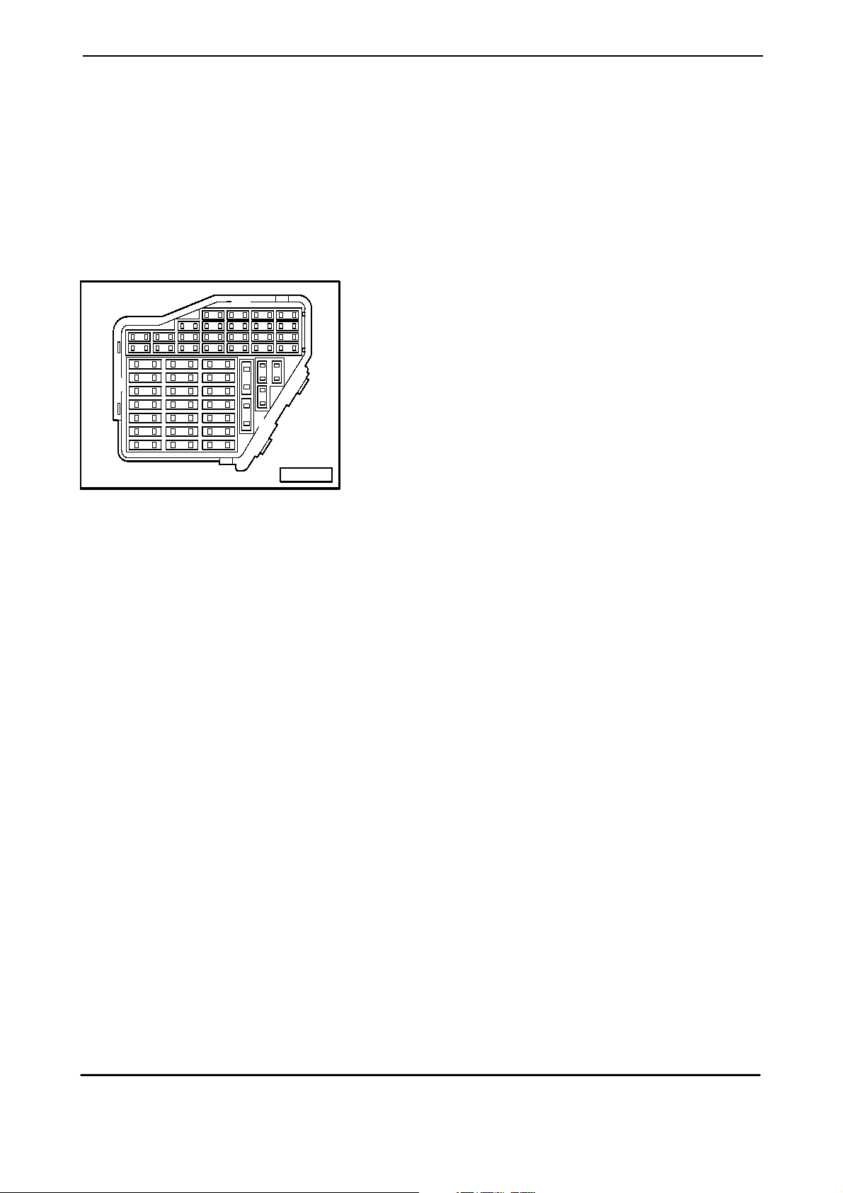
Fuse Panel :
Fuse Colors :
8 121620
1 3 6 10 14 18 22
2 4 7 11 15 19 23
24
25
26
27
28
29
30
5 9 13 17 21
31
38
32
39
33
40
34
41
35
42
36
43
37
44
A97--0022
-
-
-
-
-
Green
White
Yellow
Blue
Red
30 A
25 A
20 A
15 A
10 A
7. 5 A - B r o w n
5 A - Beige
3 A - Lilac
Fuse in fusebox from 23 onwards are numbered
223 onwards in Current Flow Diagram.
Edition 03/02
W42.5502.13.21
Page 2
No. 90/1 Audi A4
Wiring diagram
30
15
X
31
D
15
4,0
6,0
sw
ro
2
32
A
A
2,5
4,0
sw
ro
5
15
5
1,0
ro/bl
0,35
ro/bl
20
S
10A
15a
15
T8i/4
T8i/7
1,0
1,0
sw/ro
ro/bl
T3az
/1
1,0
ro/bl
T3az
A50
1,0
sw/ro
/2
1,0
sw/ro
S
10A
5a
A74
0,35
sw/ro
T10af/2 T10af/1
ws = white
sw = black
R
ro = red
br = brown
gn = green
bl = blue
gr = grey
li = lilac
ge = yellow
or = orange
23456789
1 14
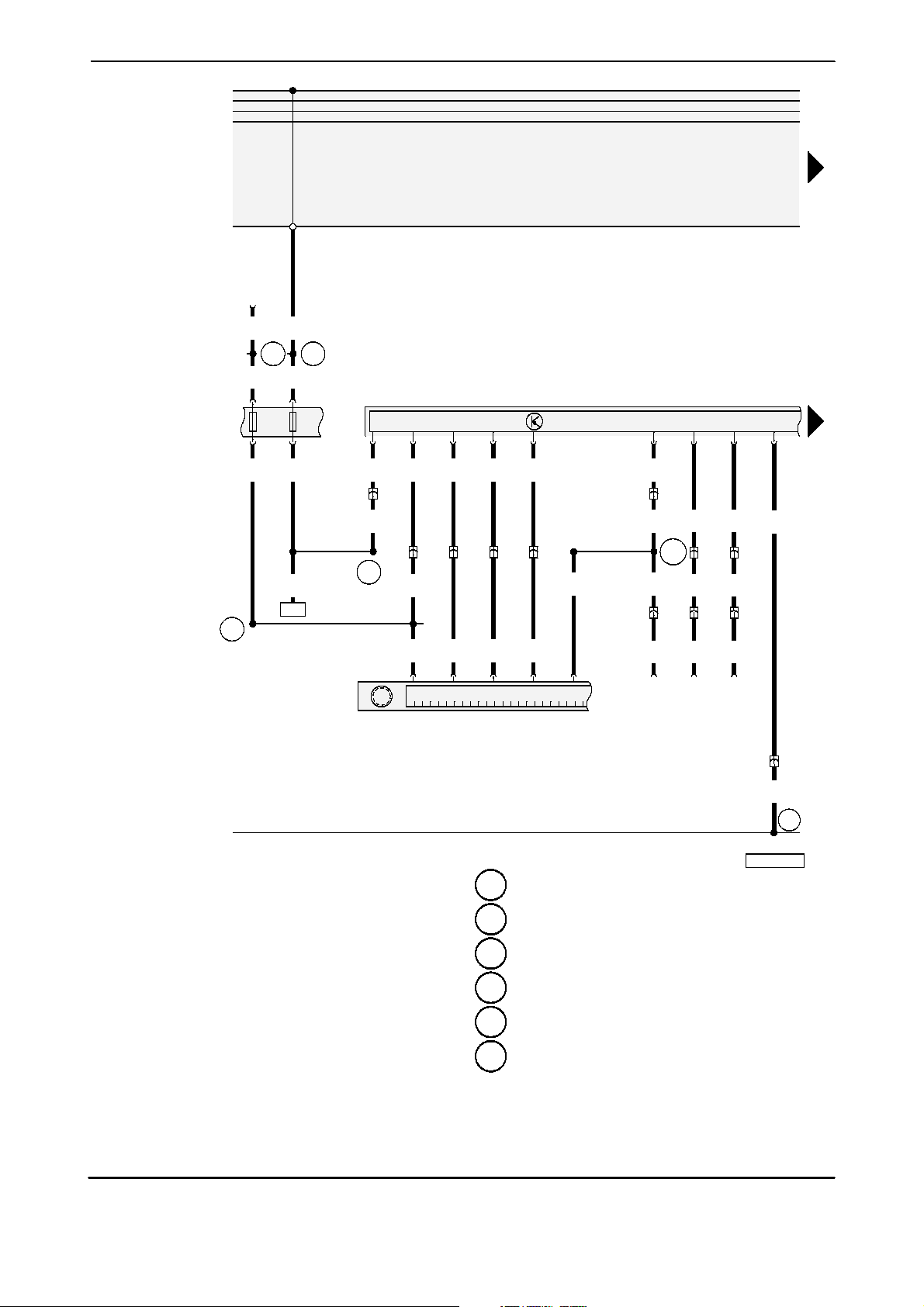
D - Ignition/Starter Switch
J40 1 - Control module for navigation with
CD-mechanism
R-Radio
R36 - Telephone Transceiver
S5 - Fuse
S15 - Fuse
T3az - Wire Connector, 3 Point, red, behind instrument
panel, left
T8i - Wire Connector, 8 Point, black, on Control
module for navigation
T1 0af- Wire Connector, 10 Point, red, on Radio
T15n - Wire Connector, 15 Point, brown, in console
T15p - Wire Connector, 15 Point, red, behind
instrument panel, left
T20c - Wire Connector, 20 Point, black, on Control
module for navigation
Navigation
J
401
T20c
0,35
li/gr
0,35
li/gr
T20c
/14
ro/sw
T15p
/5
T10af/7
0,35
0,35
gn
/13
T15p
/9
T10af/5
T20c/15
0,35
ro/br
0,35
sw
T10af/6
0,35
gr
0,35
gr
T15p
/10
0,35
gr
* * * *
0,35
R
10
gr
0,5
gr
36
11 12 13
T20c
T20c
/16
/17
T15p
/6
0,35
0,35
gn
*
A
129
15p
T
/7
0,35
0,35
ws
15n
15n
T
T
/3
/6
0,35
0,35
bl
* * *
19
10
R
R
36
sw
br
br
36
T20c
/19
T
T
25
135 - Ground connection -2-, in instrument panel
wiring harness
A2 - Plus connection (15), in instrument panel wiring
harness
A32 - plus connection (30), in instrument panel wiring
harness
A50 - Plus connection (30as), in instrument panel
wiring harness
A74 - Connector (15a, fuse 5), in instrument panel
wiring harness
- Connection (quiet switch), in instrument panel
A129
wiring harness
Edition 03/02
W42.5502.13.21
T8i/8
1,5
br
15p
/8
15n
/4
1,5
br
97--54609
T3az/3
135
30
15
X
31
Page 3

Audi A4 No. 90/2
Wiring diagram
0,5
or/li
0,35
or/li
T20c/2
15p
T
/11
B
230
30
15
X
31
30
15
X
31
87
A
0,35
1,0
bl/ro
bl/ro
T15p/2
16
17
0,35
bl/ro
T8i/2
0,35
gn/bl
0,35
gn/bl
T8i/3
15p/3
T
A
76
0,5
or/br
0,35
or/br
T20c/5
15p
T
/12
B
229
HF
M
M
J
401
A
2
0,35
ws/bl
0,35
ws/bl
T8i/1
15p
T
/1
A
60
0,35
ro/bl
T32/23
R
50
0,35
ws/bl
J
15 16 17 18 19 20 21 22 23 24 25 26
J189 - Auto Check System
J218 - Instrument Cluster Combination Processor
J40 1 - Control module for navigation with
CD-mechanism
M16 - Left Back-up Light
M17 - Right Back-up Light
R50 - Antenna for Navigation System (GPS)
T8i - Wire Connector, 8 Point, black, on Control
module for navigation
T15p - Wire Connector, 15 Point, red, behind
instrument panel, left
T20c - Wire Connector, 20 Point, black, on Control
module for navigation
T32 - Wire Connector, 32 Point, blue, on instrument
cluster
T32a - Wire Connector, 32 Point, green, on instrument
cluster
Edition 03/02
W42.5502.13.21
T32/31
218
0,35
gn/ro
T32a/28
0,35
or/br
T32b/6
0,35
or/li
T32b/5
ws = white
189
J
sw = black
ro = red
br = brown
gn = green
bl = blue
gr = grey
li = lilac
ge = yellow
or = orange
28
27
97--54610
T32b - Wire Connector, 32 Point, grey, on instrument
cluster
A60 - Wire connection (Vehicle speed signal), in
instrument panel wiring harness
A76 - Connector (K-diagosis wire), in instrument
panel wiring harness
A87 - Connector (reverse lamp), in instrument panel
wiring harness
- Connection (High-Bus) (interior wiring harness)
B229
- Connection (Low-Bus) (interior wiring harness)
B230
Navigation
Page 4

No. 90/3 Audi A4
Wiring diagram
30
15
X
31
E
272
2
3
6
7
8
0,35
gr/bl
4
30
15
X
31
10
0,35
gn
0,35
gn/gr
T32b/24T32b/23
ws = white
sw = black
ro = red
J
br = brown
gn = green
bl = blue
gr = grey
li = lilac
ge = yellow
or = orange
30 31 32 33 34 35 36 37 38 39 40 41
29
E272 - Board Computer Function Selector Switch II
J189 - Auto Check System
J218 - Instrument Cluster Combination Processor
T32 - Wire Connector, 32 Point, blue, on instrument
cluster
T32b - Wire Connector, 32 Point, grey, on instrument
cluster
189
A19
0,35
bl/ge
T32b/2
0,35
gn/li
T32b/3
0,35
ws/br
T32b/4
0,35
gr/bl
T32/20
J
T32/7
0,35
br
269
199 - Ground connection -3-, in instrument panel
wiring harness
269 - Ground connector (sensor ground) -1-, in
instrument panel wiring harness
A19 - Wire connection (58d), in instrument panel
wiring harness
- through 2000 m.y.
4
- from 2001 m.y.
44
218
*
**
0,35
br
199199
269
42
97--54611
*
**
Navigation
Edition 03/02
W42.5502.13.21
 Loading...