

Page 1
Audi A4 No. 98
Wiring diagram
Anti-lock Brake (ABS 5.3) with Electronic Differential Lock (EDL),
Anti-slip Control (ASC - ASR) and Electronic Stabilization Program (ESP)
2000 m. y. (where applicable)
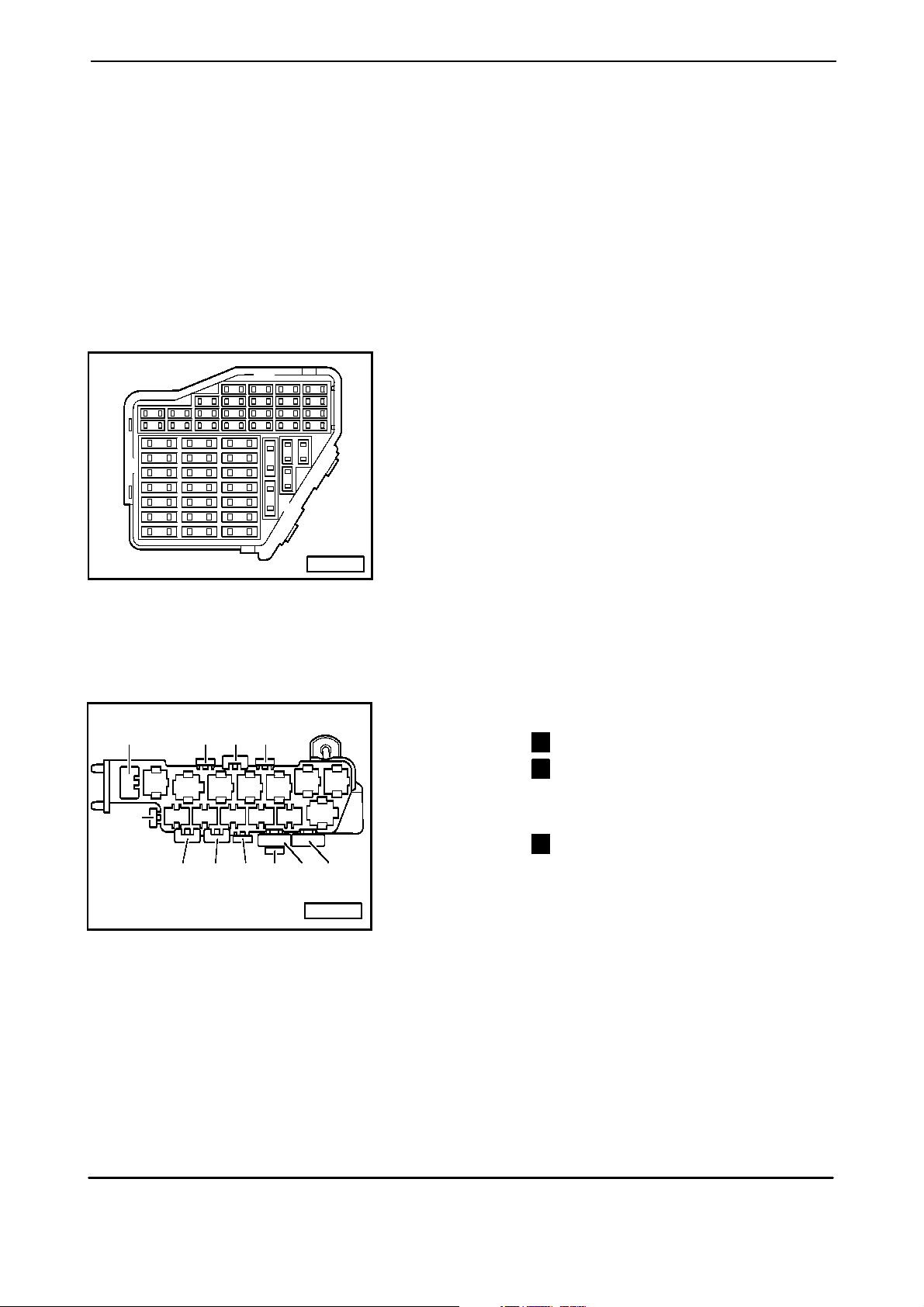
Fuse Panel :
Fuse Colors :
1 3 6 10 14 18 22
2 4 7 11 15 19 23
24
25
26
27
28
29
30
5 9 13 17 21
31
32
33
34
35
36
37
8-way Relay Carrier :
14
24
15
1
2
12 11
13
8 121620
38
39
40
41
42
43
44
A97--0022
16 17
6
543
8
9
10
-
-
-
-
-
Green
White
Yellow
Blue
Red
30 A
25 A
20 A
15 A
10 A
Fuse in fusebox from 23 onwards are numbered
223 onwards in Current Flow Diagram.
Relay Location :
- ABS Solenoid Valve Relay
4
- ABS Hydraulic Pump Relay
7
7
Fuse Location :
23 22
Edition 03/02
W42.5502.13.21
21
20
19
18
A97--0026
- ABS Hydraulic Pump Fuse
18
Page 2
No. 98/1 Audi A4
Wiring diagram
2,5
ro/ws
2,5
ro/ws
S
25A
42a
T
51
242
10b/1
30
15
X
31
30
15
X
31
30
1,0
ro/ge
**
**
6,0
ro
A32
6,0
ro
13 42
13
S
10A
13a
ro/bl
J
104
2,5
48
41
S
25A
41a
241
0,5
sw/bl
23
4
4
F
3
0,35
*
*
gn/sw
10ap/2
T
0,5
*
ro/br
42
1
23
0,5
sw/bl
24
1,0
ro/sw
18
A
0,5
ro/sw
10b/8
T
0,5
ro/sw
48
F
0,35
**
**
ws/ro
106
A
0,35
ws/ro
10ap/2
T
0,5
ro/br
42
ws = white
sw = black
ro = red
br = brown
gn = green
bl = blue
gr = grey
li = lilac
ge = yellow
or = orange
135 1314
2 4 6 7 8 9 10 11 12
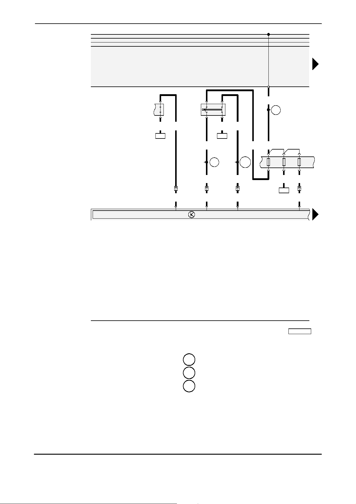
F - Brake Light Switch
J104 - ABS Control Module (w/EDL)
S13 - Fuse
S141 - Fuse for Climatronic, rear
S142 - Control module fuse for coolant fan
T1 0b - Wire Connector, 10-Point, orange, connector
station, left, A-pillar
T1 0ap- Wire Connector, 10-Point, grey, connector
station, right, A-pillar
97--54950
A18 - wire connection (54), in instrument panel wiring
harness
A32 - plus connection (30), in instrument panel wiring
harness
- Connector -2- (86s), in instrument panel wiring
A106
harness
- only for models without Electronic Power
4
Control (EPC)
- only for models with Electronic Power Control
44
(EPC)
ABS Control Module, Brake Light Switch, Fuse
Edition 03/02
W42.5502.13.21
Page 3
Audi A4 No. 98/2
Wiring diagram
0,35
sw/gn
0,5
sw/gn
T10ap/1
441
30
15
X
31
30
15
X
31
6 1
0,35
sw
83
J
D
4,0
sw
2,5
sw
2,5
sw/bl
104
15
7
S
7a
A2
10A
4
0,35
sw/bl
7
A104
0,35
br
23
0,5
sw/bl
5
E
132
3
0,35
gr/bl
A19
0,5
gr/bl
T32/20
J
218
1,5
0,5
sw/bl
9
**
sw/bl
1,5
sw/ge
T10b/4
*
28 29
2,5
4,0
br
44 100
16 18 20 21 22 23 24 25 2615 17 19 27 28
2,5
br
br
100
100
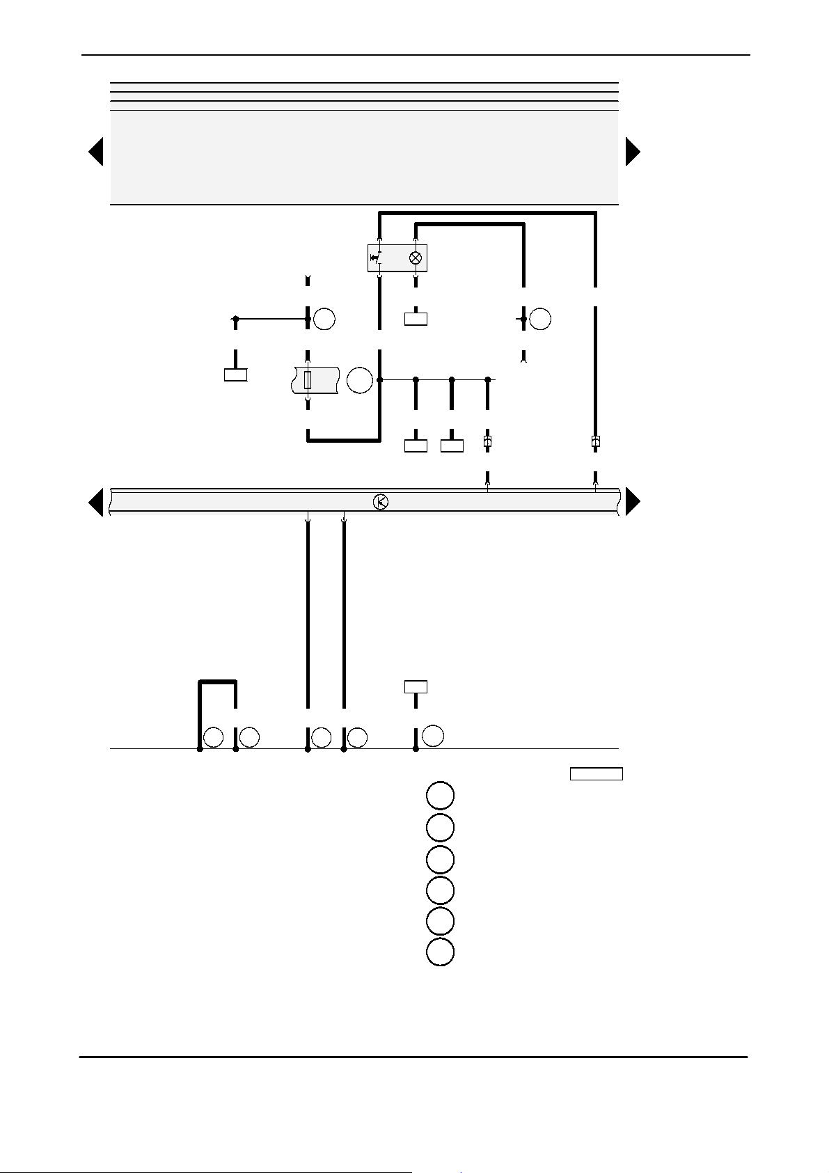
D - Ignition/Starter Switch
E132 - Anti-Slip Control Switch
J104 - ABS Control Module (w/EDL)
J218 - Instrument Cluster Combination Processor
S7 - Fuse
T1 0b - Wire Connector, 10-Point, orange, connector
station, left, A-pillar
T1 0ap- Wire Connector, 10-Point, grey, connector
station, right, A-pillar
T32 - Wire Connector, 32-Point, blue, on instrument
cluster
23
0,35
br
135
97--54951
44 - Ground connection, on left A-pillar, lower part
1 00 - Ground connection -1-, in ABS wiring harness
135 - Ground connection -2-, in instrument panel
wiring harness
A2 - plus connection (15), in instrument panel wiring
harness
A19 - Wire connection (58d), in instrument panel
wiring harness
- Plus connector -2- (15), in instrument panel
A104
wiring harness
ws = white
sw = black
ro = red
br = brown
gn = green
bl = blue
gr = grey
li = lilac
ge = yellow
or = orange
Edition 03/02
W42.5502.13.21
- only for models without Electronic Power
4
Control (EPC)
- only for models with Electronic Power Control
44
(EPC)
ABS Control Module, Fuse, Anti-Slip Control Switch
Page 4

No. 98/3 Audi A4
Wiring diagram
30
15
X
31
J
104
30
15
X
31
55
26
1,0
1,0
bl/gn
bl/ro
5
55
N
5
1,0
1,0
bl
bl/ge
9
8
ws = white
sw = black
ro = red
br = brown
N
100
99
N
101
N
102
N
gn = green
bl = blue
gr = grey
li = lilac
ge = yellow
or = orange
J104 - ABS Control Module (w/EDL)
N55 - ABS Hydraulic Unit
N99 - Right Front ABS Inlet Valve
N1 00 - Right Front ABS Outlet Valve
N1 01 - Left Front ABS Inlet Valve
N1 02 - Left Front ABS Outlet Valve
N133 - Right Rear ABS Inlet Valve
N134 - Left Rear ABS Inlet Valve
N135 - Right Rear ABS Outlet Valve
N136 - Left Rear ABS Outlet Valve
N225 - Pilot valve -1- traction control
N226 - Pilot valve -2- traction control
N227 - High pressure switch valve -1- traction control
N228 - High pressure switch valve -2- traction control
54
li
1
227
1,0
li/sw
N
52
4
228
1,0
gn/ge
133
N
6
53
1,0
1,0
gn/ro
bl/ws
2
3
134
N
N
4
12
135
1,0
N
25
gn
11
136
97--54952
50
49
3
1,0
1,0
1,0
gn/br
gn/bl
6
7
15
226
225
N
34 35 36 37 38 39 40 41 4229 30 31 32 33
N
N
ABS Control Module, ABS Hydraulic Unit
Edition 03/02
W42.5502.13.21
Page 5

Audi A4 No. 98/4
Wiring diagram
ro/sw
104
6,0
ro
6,0
30
15
X
31
30
1
S
53
50A
18
2
30
15
X
31
30
5
13
0,35
2,5
gr/bl
ro/bl
3
214
2,5
0,35
ro/sw
or/sw
76
2,5
ge
48 54
T10b
2
/5
1,0
gr/bl
1,0
ge/ws
T10ap/6
4
106
J
4
68
1,0
gr/bl
1,0
gr/bl
1,0
gr/sw
2/30
4
185
J
7
8
6
2,5
1,0
gr
gr
20736 2
J
4,0
G
85
0,35
ro/ws
ro
16a
S
16
5A
16
1,0
ro
0,35
br
45
0,35
or/br
74
A40
48 54
2,5
ge
10 14
45
0,35
br
135
43 44 45 46 47 48 49 50 51 52 53 54 55 56
G85 - Steering Angle Sensor
55
N
44 - Ground connection, on left A-pillar, lower part
J104 - ABS Control Module (w/EDL)
J106 - ABS Solenoid Valve Relay
J185 - ABS Hydraulic Pump Relay
N55 - ABS Hydraulic Unit
S16 - Fuse
135 - Ground connection -2-, in instrument panel
wiring harness
A40 - plus connection -1- (30), in instrument cluster
wiring harness
S53 - ABS Hydraulic Pump Fuse
T1 0b - Wire Connector, 10-Point, orange, connector
station, left, A-pillar
T1 0ap- Wire Connector, 10-Point, grey, connector
station, right, A-pillar
V39 - ABS Return Flow Pump
2,5
M
2,5
gr
ws = white
39
V
sw = black
ro = red
br = brown
13
gn = green
bl = blue
gr = grey
br
44
97--54953
li = lilac
ge = yellow
or = orange
Edition 03/02
W42.5502.13.21
ABS Control Module, Steering Angle Sensor, ABS Hydraulic Pump Fuse, ABS Solenoid Valve Relay, ABS Hydraulic Pump Relay, ABS Return Flow Pump
Page 6

No. 98/5 Audi A4
Wiring diagram
0,5
gn/sw
30
15
X
31
21
8
*
910
**
30
15
X
31
2,5
ro/ws
M
2,5
ro/sw
2
V
156
1
2422
0,5
br/sw
G
44
0,5
br/sw
21
0,5
ge/sw
J
1112 1516
104
G
45
21
0,5
ge/sw
0,5
ws/sw
G
46
21
0,5
ws/sw
1314
0,5
gn/sw
G
47
67 68 69
0,5
ro
0,5
ge/gn
0,5
ge/sw
123
ws = white
sw = black
ro = red
G
201
br = brown
gn = green
bl = blue
gr = grey
li = lilac
ge = yellow
or = orange
58 60 62 63 64 65 66 67 6857 59 61 69 70
G44 - Right Rear ABS Wheel Speed Sensor
G45 - Right Front ABS Wheel Speed Sensor
G46 - Left Rear ABS Wheel Speed Sensor
G47 - Left Front ABS Wheel Speed Sensor
G200 - Sensor for transverse acceleration
G20 1 - Sender 1 for brake booster
G202 - Sender for Rotation Rate
J104 - ABS Control Module (w/EDL)
T1 0ap- Wire Connector, 10-Point, grey, connector
station, right, A-pillar
V156 - Hydraulic pump for traction control
31 71
0,5
ws/li
T10ap/3
0,5
ws/gn
34 80 77 18 78 79
1,0
1,0
ws/bl
ws/li
ws/ro
T10ap/4
G
- only for models with Quattro
4
- only for models without Quattro
44
1,0
321 654
200
1,0
gn/sw
G
202
1,0
ws/ge
1,0
ws
97--54954
Wheel Speed Sensor, Sensor for transverse acceleration, Sender 1 for brake booster, Sender for Rotation Rate, Hydraulic pump for traction control
Edition 03/02
W42.5502.13.21
Page 7

Audi A4 No. 98/6
Wiring diagram
30
15
X
31
J
218
86
0,35
br/ro
0,5
br/ro
0,35
br/ws
K
T32/32 T32/1T32/24T32a
10b/10
T
1
K
0,35
gn
0,35
gn/sw
0,5
gn/sw
T16
T
46
/7
10b/2
0,35
gn/ro
76
A
K
47
28
0,35
ge/ro
10b
T
/6
0,5
sw/ro
0,35
122
A
or/br
0,35
0,35
or/br
0,35
or/br
T
Low
64
10b
/3
or/sw
or/br
46 47
A121
0,35
0,35
or/sw
0,35
or/sw
0,35
or/sw
T32a/18T32a/19T32a/21T32a/
T
High
66
10b/7
gr/ge
br/ws
0,5
0,5
76
10ap/5
T
/11
0,35
0,35
gn
br
91
A
0,35
gn
0,5
gn
T
86 7032
10b/9
81 18
A24
F
2
81
0,35
0,35
br
br
81
81
71 72 73 74 75 76 77 78 79 8 81 82 83 84
0,35
9
sw
J
104
K
T32a
/13
0,35
br/ws
97--54955
30
15
X
31
7
ws = white
sw = black
ro = red
br = brown
gn = green
bl = blue
gr = grey
li = lilac
ge = yellow
or = orange
F9 - Parking Brake Warning Light Switch
J104 - ABS Control Module (w/EDL)
J218 - Instrument Cluster Combination Processor
K7 - Brake and Parking Brake Warning Light
K47 - ABS Warning Light
K86 - T raction Control Indicator Light
T1 0b - Wire Connector, 10-Point, orange, connector
station, left, A-pillar
T1 0ap- Wire Connector, 10-Point, grey, connector
station, right, A-pillar
T16 - Wire Connector, 16-Point, behind instrument
panel, left (diagnostic connection)
T32 - Wire Connector, 32-Point, blue, on instrument
cluster
T32a - Wire Connector, 32-Point, green, on instrument
cluster
Edition 03/02
W42.5502.13.21
ABS Control Module, Parking Brake Warning Light Switch, Instrument Cluster Combination Processor
81 - Ground connection -1-, in instrument panel
wiring harness
A24 - wire connection (brake system monitoring), in
instrument panel wiring harness
A76 - Connection (K-diagnosis wire), in instrument
panel wiring harness
A91 - Connector (signal for instrument panel insert),
in instrument panel wiring harness
- Connection (high bus) in instrument panel
A121
wiring harness
- Connection (low bus) in instrument panel wiring
A122
harness
Page 8

No. 98/7 Audi A4
Wiring diagram
0,5
br/gn
30
15
X
31
*
*
30
15
X
31
J
218
T32/2
0,35
br/gn
10ap/7
T
34
G
2 1
G
1 2
0,5
sw
*
36
G
0,5
35
br/gn
*
34
G
2 1
0,5
* *
sw
**
2/1T2/2
T
0,5
*
sw
*
0,5
sw
0,5
br/bl
G
T
37
2/1T2/2
*
*
G
1 2
0,5
*
sw
*
35
ws = white
sw = black
ro = red
br = brown
gn = green
bl = blue
gr = grey
li = lilac
ge = yellow
or = orange
0,5
br
*
100
85 86 87 88 89 90 91 92 93 22 95 96 97 98
G34 - Left Front Brake Pad Wear Sensor
G35 - Right Front Brake Pad Wear Sensor
G36 - Left Rear Brake Pad Wear Sensor
G37 - Right Rear Brake Pad Wear Sensor
J218 - Instrument Cluster Combination Processor
T2 - Wire Connector, double, red, right rear
T2a - Wire Connector, double, red, left rear
T1 0ap- Wire Connector, 10-Point, grey, connector
station, right, A-pillar
T32 - Wire Connector, 32-Point, blue, on instrument
cluster
0,5
*
br
*
100
1 00 - Ground connection -1-, in ABS wiring harness
- not for RS4
4
- only for RS4
44
97--54956
Brake Pad Wear Sensor
Edition 03/02
W42.5502.13.21
 Loading...