

Page 1

uar 2007 1:32 13
Audi R8
Owner's Manual
Audi R8 englisch 03.07
Page 2

n
t
t
m
2
e
i
ruar 2007 1:32 13
© 2007 AUDI AG
AUDI AG works continuously to develop and further improve all
models. You will appreciate that we must therefore reserve the right
to alter any part of the vehicle and its equipment or technical specifications at any time. No legal commitment can therefore be
implied by the information, illustrations or descriptions in this
Manual.
No part of this Owner's Ma
translated without the writ
under the laws of copyrigh
Subject to alteration and a
Date of publication: 02.02.
For the sake of the
This paper was bleached w
Page 3

document_0900452a816e6cc9.book Seite 1 Mittwoch, 21. Februar 2007 1:32 13
Foreword
Thank you for choosing the Audi R8.
The new Audi R8 combines the latest technology with numerous features for your comfort and
convenience. To help you get the best out of these features in everyday use, we recommend that
you read this Manual carefully.
As well as information on how to use the controls and equipment, the Owner's Manual contains
important notes on care and maintenance. These are relevant to your safety and will help preserve
your car's value.
In addition to this Owner's Manual, the Service Wallet also includes the Operating Manual for your
infotainment system and the Service Schedule. The Service Schedule contains important information on Audi service requirements and lists the vehicle's fuel consumption figures. We recommend
that you keep the Service Wallet in the car at all times.
Our Audi R8 dealers are comprehensively trained and qualified to ensure that you receive the
highest level of quality, comfort and convenience. Should you have any further questions
regarding your car or if you suspect that your owner's literature is not complete, please contact
your Audi R8 dealer or importer. They are always glad to answer your queries and note any suggestions you may have.
We wish you safe and enjoyable motoring with your Audi R8.
AUDI AG
Page 4

document_0900452a816e6cc9.book Seite 2 Mittwoch, 21. Februar 2007 1:32 13
Contents2
Contents
Notes on this Owner's
Manual
. . . . . . . . . . . . . . . . . . . . . .
Controls . . . . . . . . . . . . . . . . . . . . .
Controls and displays . . . . . . . . . .
Overview . . . . . . . . . . . . . . . . . . . . . .
Instruments and
warning/indicator lamps . . . . . . .
Instruments . . . . . . . . . . . . . . . . . . . .
Warning and indicator lamps . . . . .
Driver information system . . . . . .
Introduction . . . . . . . . . . . . . . . . . . . .
Service interval display . . . . . . . . . .
On-board computer . . . . . . . . . . . . .
Menus . . . . . . . . . . . . . . . . . . . . . . . . .
Lap timer . . . . . . . . . . . . . . . . . . . . . .
Speed warning function . . . . . . . . .
Notes and symbols . . . . . . . . . . . . .
Doors and windows . . . . . . . . . . . .
Remote control keys . . . . . . . . . . . .
Central locking system . . . . . . . . . .
Luggage lid . . . . . . . . . . . . . . . . . . . .
Anti-theft alarm system . . . . . . . . . .
Electric windows . . . . . . . . . . . . . . .
Lights and vision . . . . . . . . . . . . . .
Lights . . . . . . . . . . . . . . . . . . . . . . . . .
5
Interior lights . . . . . . . . . . . . . . . . . .
Clear vision . . . . . . . . . . . . . . . . . . . .
Windscreen wipers . . . . . . . . . . . . .
Rear-view mirrors . . . . . . . . . . . . . .
Digital compass . . . . . . . . . . . . . . . .
Seats and storage . . . . . . . . . . . . .
Manually adjustable front seats . .
Electrically adjustable front seats
Bucket seats . . . . . . . . . . . . . . . . . . .
7
Head restraints . . . . . . . . . . . . . . . .
Cup holders . . . . . . . . . . . . . . . . . . .
9
Ashtray . . . . . . . . . . . . . . . . . . . . . . .
9
Cigarette lighter and electrical
socket . . . . . . . . . . . . . . . . . . . . . . . .
10
Storage compartments . . . . . . . . .
10
Heating and cooling . . . . . . . . . . .
15
Air conditioner . . . . . . . . . . . . . . . . .
20
Rear window heating . . . . . . . . .
20
Seat heating . . . . . . . . . . . . . . . . . . .
21
Driving . . . . . . . . . . . . . . . . . . . . . . . . .
22
Steering . . . . . . . . . . . . . . . . . . . . . . .
24
Ignition lock . . . . . . . . . . . . . . . . . . .
27
Starting the engine . . . . . . . . . . . . .
31
Switching off the engine . . . . . . . .
33
Handbrake . . . . . . . . . . . . . . . . . . . .
40
Parking aid . . . . . . . . . . . . . . . . . . . .
40
Cruise control system . . . . . . . . . .
42
Audi magnetic ride . . . . . . . . . . . . .
47
Automatic gearbox . . . . . . . . . . . .
48
Description . . . . . . . . . . . . . . . . . . . .
50
Manual mode . . . . . . . . . . . . . . . . . .
Automatic mode . . . . . . . . . . . . . . .
Kick-down feature . . . . . . . . . . . . . .
Launch control programme . . . . . .
52
Steering wheel with paddle levers
52
Backup programme . . . . . . . . . . . . .
57
58
HomeLink . . . . . . . . . . . . . . . . . . . . . .
59
Universal transmitter . . . . . . . . . . . .
63
65
67
67
68
70
71
72
72
Safety . . . . . . . . . . . . . . . . . . . . . . .
72
Safe driving . . . . . . . . . . . . . . . . . . . .
73
General notes . . . . . . . . . . . . . . . . . .
Correct sitting positions . . . . . . . . .
75
Pedal area . . . . . . . . . . . . . . . . . . . . .
75
Stowing luggage safely . . . . . . . . .
79
80
Seat belts . . . . . . . . . . . . . . . . . . . . . .
Why is it so important to use seat
81
belts? . . . . . . . . . . . . . . . . . . . . . . . . .
81
Forces acting in a collision . . . . . .
81
How to wear seat belts properly .
82
Belt tensioners . . . . . . . . . . . . . . . . .
83
Airbag system . . . . . . . . . . . . . . . . . .
83
85
Description of airbag system . . . .
86
Front airbags . . . . . . . . . . . . . . . . . .
88
Side airbags . . . . . . . . . . . . . . . . . . .
Deactivating the airbags . . . . . . . .
90
90
91
92
92
93
93
94
95
95
101
102
102
104
107
108
109
109
110
112
114
115
115
116
118
120
Page 5

document_0900452a816e6cc9.book Seite 3 Mittwoch, 21. Februar 2007 1:32 13
Contents 3
Child safety . . . . . . . . . . . . . . . . . . . .
Points to remember if children are
travelling in the car . . . . . . . . . . . . .
Child safety seats . . . . . . . . . . . . . .
Fitting child safety seats . . . . . . . .
Driving tips . . . . . . . . . . . . . . . .
Intelligent technology . . . . . . . . . .
Electronic stabilisation program
(ESP) . . . . . . . . . . . . . . . . . . . . . . . . . .
Rear spoiler . . . . . . . . . . . . . . . . . . .
Brakes . . . . . . . . . . . . . . . . . . . . . . . .
Power steering . . . . . . . . . . . . . . . . .
Four-wheel drive (quattro®) . . . . . .
Dry sump lubrication system . . . .
Your vehicle and the
environment . . . . . . . . . . . . . . . . . . .
Running in . . . . . . . . . . . . . . . . . . . .
Emission control systems . . . . . . .
Driving abroad . . . . . . . . . . . . . . . . .
Sporty driving . . . . . . . . . . . . . . . . .
Environmental compatibility . . . . .
122
122
123
126
General maintenance . .
Care of vehicle and cleaning . . .
General notes . . . . . . . . . . . . . . . . . .
Care of exterior . . . . . . . . . . . . . . . . .
Care of interior . . . . . . . . . . . . . . . . .
Fuel and filling the tank . . . . . . . .
131
132
132
134
134
136
136
137
138
138
138
138
139
139
Petrol . . . . . . . . . . . . . . . . . . . . . . . . .
Filling the tank . . . . . . . . . . . . . . . . .
Checking and topping up fluids
Engine lid . . . . . . . . . . . . . . . . . . . . . .
Engine oil . . . . . . . . . . . . . . . . . . . . . .
Cooling system . . . . . . . . . . . . . . . . .
Brake fluid . . . . . . . . . . . . . . . . . . . . .
Battery . . . . . . . . . . . . . . . . . . . . . . . .
Windscreen washer . . . . . . . . . . . . .
Wheels and tyres . . . . . . . . . . . . . . .
Wheels . . . . . . . . . . . . . . . . . . . . . . . .
Tyre pressure monitoring system .
Accessories and modifications
to the vehicle . . . . . . . . . . . . . . . . . .
Accessories, replacement parts and
repairs . . . . . . . . . . . . . . . . . . . . . . . .
Modifications . . . . . . . . . . . . . . . . . .
Radio transmitters and business
equipment . . . . . . . . . . . . . . . . . . . . .
143
Self-help . . . . . . . . . . . . . . . . . . . . .
144
Self-help . . . . . . . . . . . . . . . . . . . . . . . .
144
144
147
152
152
152
155
155
157
159
161
162
164
166
166
172
174
174
174
175
Breakdown kit . . . . . . . . . . . . . . . . . .
Repairing a tyre . . . . . . . . . . . . . . . . .
Changing a wheel . . . . . . . . . . . . . .
Jump-starting . . . . . . . . . . . . . . . . . .
Tow-starting and towing away . . .
Fuses and bulbs . . . . . . . . . . . . . . . .
Fuses . . . . . . . . . . . . . . . . . . . . . . . . . .
Bulbs . . . . . . . . . . . . . . . . . . . . . . . . . .
Technical data . . . . . . . . . . . .
General notes . . . . . . . . . . . . . . . . . .
Notes . . . . . . . . . . . . . . . . . . . . . . . . . .
Vehicle identification data . . . . . . .
Performance, weights and
dimensions . . . . . . . . . . . . . . . . . . . . .
R8 4.2 quattro . . . . . . . . . . . . . . . . . .
Dimensions . . . . . . . . . . . . . . . . . . . .
Capacities . . . . . . . . . . . . . . . . . . . . .
177
178
178
178
182
185
187
190
190
193
195
196
196
196
198
198
198
199
Controls Safety Driving tips General maintenance Self-help Technical data
Page 6

document_0900452a816e6cc9.book Seite 4 Mittwoch, 21. Februar 2007 1:32 13
Contents4
Index . . . . . . . . . . . . . . . . . . . . . . . . .
201
Page 7

document_0900452a816e6cc9.book Seite 5 Mittwoch, 21. Februar 2007 1:32 13
Notes on this Owner's Manual
This Owner's Manual contains important information, tips, suggestions and warnings.
Please ensure that this Owner's Manual is always kept in the vehicle.
It should always be available to anyone else driving the vehicle, i.e.
anyone renting, borrowing or buying the vehicle from you.
This manual describes the equipment available for the vehicle at the
time of going to print. Some of the equipment described here will
not be available until a later date, or may only be available in certain
markets.
Some sections of this Owner's Manual do not apply to all vehicles.
If this is the case, a text at the start of the section indicates which
vehicles it applies to, e. g. “Applies to vehicles: with R tronic”. This
optional equipment is also marked with an asterisk “*”.
Illustrations are intended as a general guide, and may vary from the
equipment fitted in your vehicle in some details.
At the beginning of this Owner's Manual, you will find a table of
contents showing all the items described in this manual in the order
in which they appear. An alphabetical index is included at the end
of the Owner's Manual.
All references to positions such as “left”, “right”, “front” or “rear”
are given as seen facing in the direction of travel.
* optional equipment
The section is continued on the following page.
Denotes the end of a section.
® Registered trademarks are marked ®. However, the absence of
this symbol does not constitute a waiver of the rights
concerning any proprietary name.
⇒ Refers to a “WARNING” within the same section. If the
WARNING symbol is followed by a page number the warning text
referred to is included in a different section.
Notes on this Owner's Manual 5
WARNING
Texts with this symbol contain safety information. They warn you
of serious dangers, possibly involving accident or injury.
Caution
Texts with this symbol draw your attention to a possible risk of
damage to your vehicle.
For the sake of the environment
Texts with this symbol refer to points relevant to the protection of
the environment.
Note
Texts with this symbol contain additional information of a more
general nature.
Controls Safety Driving tips General maintenance Self-help Technical data
Page 8

document_0900452a816e6cc9.book Seite 6 Mittwoch, 21. Februar 2007 1:32 13
6
Page 9

document_0900452a816e6cc9.book Seite 7 Mittwoch, 21. Februar 2007 1:32 13
7Controls
Page 10

document_0900452a816e6cc9.book Seite 8 Mittwoch, 21. Februar 2007 1:32 13
Controls and displays8
Fig. 1 Some of the items of equipment listed in this section are only fitted on certain models or are optional extras.
Page 11

A
A
A
A
A
A
A
A
A
A
A
A
A
A
A
A
A
A
A
A
A
A
A
A
A
document_0900452a816e6cc9.book Seite 9 Mittwoch, 21. Februar 2007 1:32 13
Controls and displays
Controls and displays 9
Overview
1
Electric windows . . . . . . . . . . . . . . . . . . . . . . . . . . . . . . .
2
Door handle
3
Central locking switch . . . . . . . . . . . . . . . . . . . . . . . . . . .
4
Electric adjuster for exterior mirrors . . . . . . . . . . . . . . .
5
Switches for
− Unlocking the luggage lid . . . . . . . . . . . . . . . . . . . . .
− Unlocking the fuel tank flap . . . . . . . . . . . . . . . . . . . .
6
Air outlets . . . . . . . . . . . . . . . . . . . . . . . . . . . . . . . . . . . . .
7
Light switch . . . . . . . . . . . . . . . . . . . . . . . . . . . . . . . . . . .
8
Lever for turn signals and main beam headlights . . . .
9
Steering wheel with:
− Horn
− Driver's airbag . . . . . . . . . . . . . . . . . . . . . . . . . . . . . . .
− Controls for audio, telephone and speech dialogue
system
− Paddle levers for manual gearshift (R tronic) . . . . . .
10
Instrument cluster . . . . . . . . . . . . . . . . . . . . . . . . . . . . . .
11
Levers and switches for:
− Windscreen wipers and washer . . . . . . . . . . . . . . . . .
− On-board computer . . . . . . . . . . . . . . . . . . . . . . . . . . .
− Menu display . . . . . . . . . . . . . . . . . . . . . . . . . . . . . . . .
− Lap timer . . . . . . . . . . . . . . . . . . . . . . . . . . . . . . . . . . .
− Speed warning function . . . . . . . . . . . . . . . . . . . . . . .
12
Navigation system
13
Lockable glove box . . . . . . . . . . . . . . . . . . . . . . . . . . . . .
14
Front passenger's airbag . . . . . . . . . . . . . . . . . . . . . . . .
15
Switch for heated rear window . . . . . . . . . . . . . . . . . . .
50
45
64
47
152
77
52
56
116
93
10
59
22
24
27
31
73
116
79
16
Air conditioner . . . . . . . . . . . . . . . . . . . . . . . . . . . . . . . . .
17
Gear lever/selector lever for:
− Manual gearbox
− R tronic . . . . . . . . . . . . . . . . . . . . . . . . . . . . . . . . . . . . .
18
Controls for:
− Audi magnetic ride . . . . . . . . . . . . . . . . . . . . . . . . . . .
− Electronic Stabilisation Program (ESP) . . . . . . . . . . .
− Hazard warning lights . . . . . . . . . . . . . . . . . . . . . . . . .
− Automatic rear spoiler . . . . . . . . . . . . . . . . . . . . . . . . .
− Audi parking system . . . . . . . . . . . . . . . . . . . . . . . . . .
19
Ashtray, cigarette lighter/socket
20
Handbrake . . . . . . . . . . . . . . . . . . . . . . . . . . . . . . . . . . . . .
21
Ignition lock . . . . . . . . . . . . . . . . . . . . . . . . . . . . . . . . . . .
22
Adjustable steering column . . . . . . . . . . . . . . . . . . . . . .
23
Lever for cruise control . . . . . . . . . . . . . . . . . . . . . . . . . .
24
Instrument lighting . . . . . . . . . . . . . . . . . . . . . . . . . . . . .
25
Engine lid lock release . . . . . . . . . . . . . . . . . . . . . . . . . . .
75
90
88
132
56
134
85
83
81
81
86
55
155
Note
• Separate operating instructions are enclosed if the vehicle is
equipped with a factory-fitted navigation system.
• The arrangement of switches and controls on right-hand drive
models* may be slightly different from the layout shown in
⇒ page 8, fig. 1. However, the symbols used to identify the controls
are the same.
Controls Safety Driving tips General maintenance Self-help Technical data
Page 12

A
A
A
A
A
A
A
A
A
A
document_0900452a816e6cc9.book Seite 10 Mittwoch, 21. Februar 2007 1:32 13
Instruments and warning/indicator lamps10
Instruments and warning/indicator lamps
Instruments
Instrument cluster overview
The instrument cluster is the driver's information centre.
Fig. 2 Instrument cluster
1
Engine oil temperature gauge . . . . . . . . . . . . . . . . . . . .
2
Rev counter incorporating digital clock and date . . . .
3
Warning and indicator lamps . . . . . . . . . . . . . . . . . . . .
4
Coolant temperature gauge . . . . . . . . . . . . . . . . . . . . . .
5
Fuel gauge . . . . . . . . . . . . . . . . . . . . . . . . . . . . . . . . . . . .
6
Speedometer with mileage recorder . . . . . . . . . . . . . .
7
Voltmeter . . . . . . . . . . . . . . . . . . . . . . . . . . . . . . . . . . . . .
8
Adjuster/test button . . . . . . . . . . . . . . . . . . . . . . . . . . . .
11, 12
12, 34
9
Driver information system . . . . . . . . . . . . . . . . . . . . . . .
10
Reset button for trip recorder . . . . . . . . . . . . . . . . . . . .
The needles on the dials in the instrument cluster are illuminated
when the ignition is switched on. The main instrument lighting (for
the dials and needles) comes on when the vehicle's lights are
switched on.
Engine oil temperature gauge
The engine oil temperature gauge ⇒ fig. 2 only works when the ignition is switched on. In order to avoid possible damage to the engine,
please read the following notes for the different temperature
ranges.
Engine cold
If the needle is still in the lower range of the dial, this indicates that
the engine oil has not yet reached operating temperature. Avoid
high engine speeds, full acceleration and heavy engine loads.
Normal temperature
In normal operation the needle will settle somewhere in the centre
of the dial once the engine has reached operating temperature. The
needle may also go further up when the engine is working hard at
high outside temperatures. This is no cause for concern provided
10
the warning lamp in the display does not start flashing.
15
Warning lamp
12
If the symbol in the display flashes, either the engine oil temper-
13
ature is too high, or the engine oil level is too low ⇒ page 157.
13
If the needle is at the top end of the dial, this means the engine oil
14
temperature is too high. Stop the vehicle, switch off the engine and
wait for it to cool down. If the warning lamp starts flashing again
after just a short distance, contact a qualified workshop.
20
13
Page 13

A
document_0900452a816e6cc9.book Seite 11 Mittwoch, 21. Februar 2007 1:32 13
Instruments and warning/indicator lamps 11
Rev counter
The rev counter indicates the number of engine revolutions per minute.
You should select a lower gear if the engine speed drops below
1500 rpm. The start of the red zone on the dial indicates the
maximum engine speed which may be used briefly when the engine
is warm and after it has been run in properly. However, it is advisable
to change up a gear or lift your foot off the accelerator (or shift out
of the R tronic sport mode) before the needle reaches the red zone.
Caution
Never allow the rev counter needle ⇒ page 10, fig. 2 to go into
the red zone on the scale for more than a very brief period: there is
a risk of damaging the engine. The start of the red zone on the dial
is different for some engine versions.
2
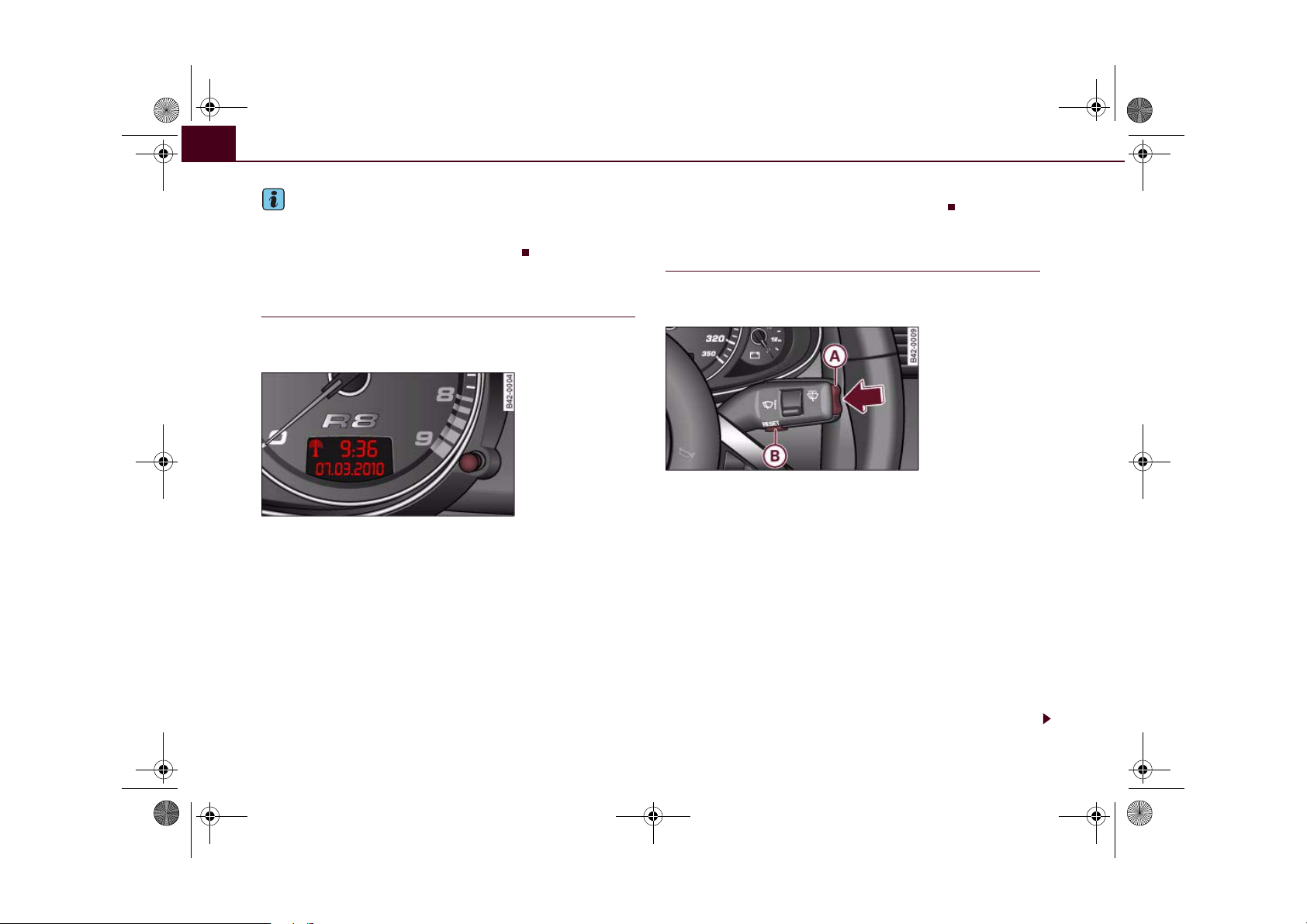
Radio-controlled clock
Fig. 3 Detail of the
instrument cluster:
Display with signal
reception symbol, time
and date
different time zone, the hour display will need to be
adjusted manually to local time using the adjuster button.
Setting the time zone
– Keep pulling the button ⇒ fig. 3 briefly until the time
zone display flashes (select setting “0” if you do not wish
to change the time zone).
– Then turn the button to the left (to set an earlier time
zone: -1/-2) or to the right (to set a later time zone: +1/+2).
Switching date display on and off
– Keep pulling the button briefly until the date display
flashes.
– Then turn the button to the left or right.
When the display stops flashing, this means the setting you are
performing is completed and the time zone has been successfully
stored.
If the clock does not receive a radio signal for three consecutive
days, it will automatically switch to “quartz” mode. The signal reception symbol will then disappear. If you need to reset the time and
date, proceed as described on ⇒ page 12.
When the clock is in “radio-control” mode the signal reception symbol (a radio tower with radio waves) appears in the
display ⇒ fig. 3. It is then not possible to change the
minutes or the date manually. If you take your vehicle into a
Controls Safety Driving tips General maintenance Self-help Technical data
Page 14

A8A
document_0900452a816e6cc9.book Seite 12 Mittwoch, 21. Februar 2007 1:32 13
Instruments and warning/indicator lamps12
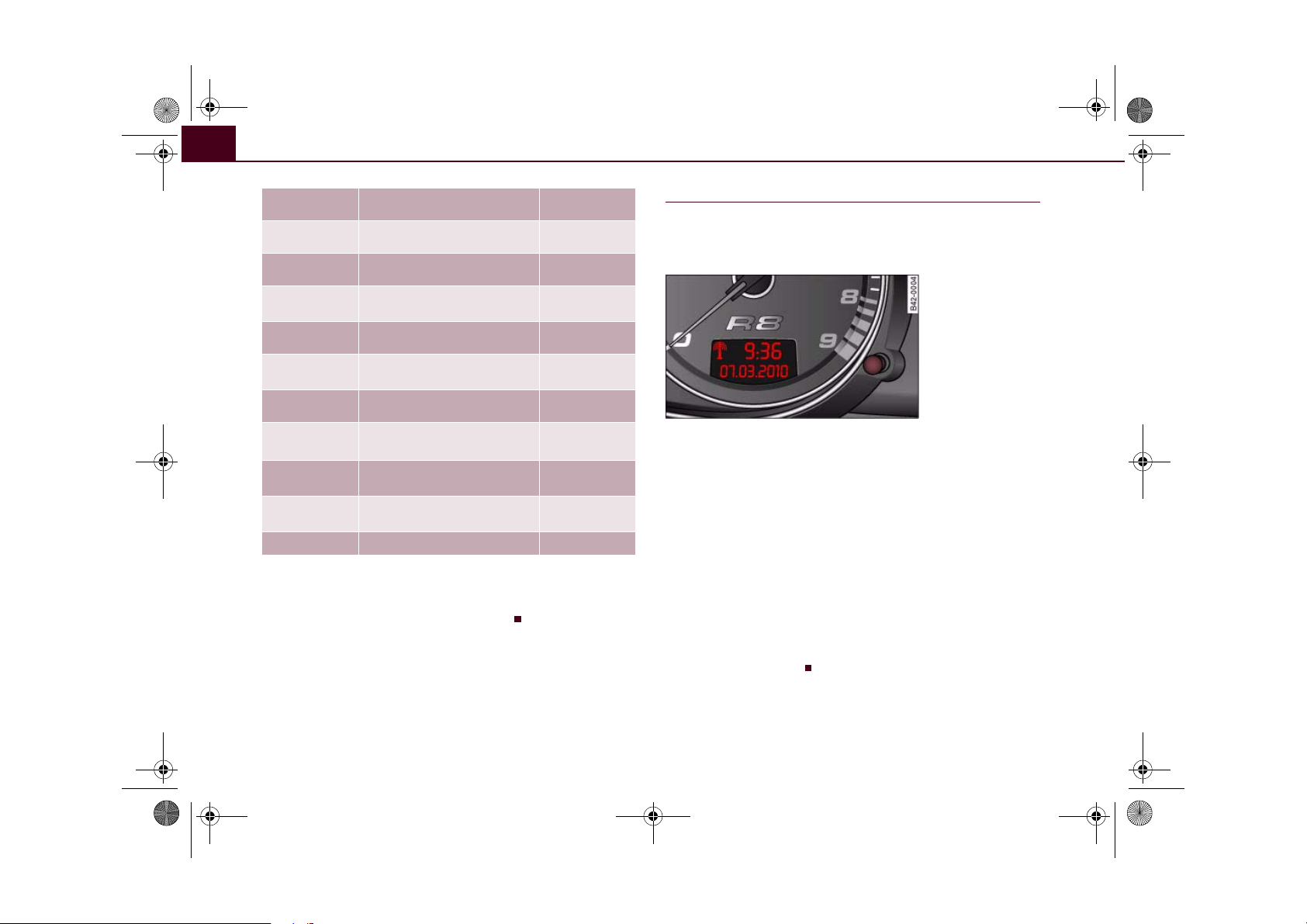
Digital clock with date display
The vehicle is equipped with either a radio-controlled
clock or a normal quartz clock with date display.
Fig. 4 Detail of the
instrument cluster:
Digital clock and date
display
The time and date are set using the button ⇒ fig. 4.
Setting the hour
– Pull the adjuster button (the hour display will flash). Then
turn the button to the left or right to alter the hour.
Setting the minutes
– Keep pulling the button briefly until the minutes display
flashes.
– Then turn the button to the left or right accordingly.
Setting time format (12 or 24 hour display)
– Keep pulling the button briefly until the time format
display flashes.
– Then turn the button to the left or right.
Setting the date
– Keep pulling the button briefly until the day, month or
year flashes.
– Then turn the button to the left or right.
When the display stops flashing, this means the setting you are
performing is completed and the time and date have been successfully stored.
When the ignition is switched off, the display illumination can be
switched on for a few seconds by pressing the adjuster/test button
⇒ page 10, fig. 2 .
Coolant temperature gauge
The coolant temperature gauge ⇒ page 10, fig. 2 only works
when the ignition is switched on. In order to avoid possible damage
to the engine, please read the following notes for the different
temperature ranges.
Engine cold
If the needle is still on the left of the dial, this indicates that the
engine has not yet reached operating temperature. Avoid high
engine speeds, full acceleration and heavy engine loads.
Normal temperature
In normal operation the needle will settle somewhere in the centre
of the dial once the engine has reached operating temperature. The
needle may also go further over to the right when the engine is
working hard at high outside temperatures. This is no cause for
concern provided the warning lamp in the display does not start
flashing.
4
Page 15

document_0900452a816e6cc9.book Seite 13 Mittwoch, 21. Februar 2007 1:32 13
Instruments and warning/indicator lamps 13
Warning lamp
If the symbol flashes in the display, this means that either the
coolant temperature is too high or the coolant level is too low
⇒ page 35.
If the needle is over to the far right on the dial, this means the
coolant temperature is too high. Stop the vehicle, switch off the
engine and wait for it to cool down. If the warning lamp starts
flashing again after just a short distance, contact a qualified workshop.
WARNING
• Before opening the engine lid and checking the coolant level,
please observe the warning information on ⇒ page 155, “Working
on components in the engine compartment”.
• Never open the engine lid if you can see or hear steam or
coolant escaping from the engine compartment; there is a risk of
being scalded. Wait until you can no longer see or hear escaping
steam or coolant.
Caution
• Additional lights and other accessories in front of the air inlet
reduce the cooling effect of the radiator. At high outside temperatures and high engine loads, there is a risk of the engine overheating.
• The front spoiler also ensures proper distribution of the cooling
air when the vehicle is moving. If the spoiler is damaged this can
reduce the cooling effect, which could cause the engine to overheat.
You should obtain professional assistance.
Fuel gauge
The gauge only works when the ignition is switched on. When the
needle reaches the reserve zone, the symbol lights up in the
instrument cluster display ⇒ page 36. At this point there are still
about 10 litres of fuel left in the tank. This is your reminder to fill up
soon.
The tank capacity of your vehicle is given in the Technical data
section ⇒ page 198.
Caution
Never run the tank completely dry. If there is an irregular fuel supply,
misfiring can occur. This allows unburnt fuel to enter the exhaust
system, which could cause overheating and damage the catalytic
converter.
Speedometer with mileage recorder
This instrument indicates the speed of the vehicle and the
distance travelled.
Fig. 5 Detail of the
instrument cluster:
Mileage recorder with
reset button
The mileage is normally stated in kilometres (km). On some models,
however, the mileage recorder will show miles.
Lower mileage recorder (odometer)
The lower counter records the vehicle's total mileage.
Controls Safety Driving tips General maintenance Self-help Technical data
Page 16

A
document_0900452a816e6cc9.book Seite 14 Mittwoch, 21. Februar 2007 1:32 13
Instruments and warning/indicator lamps14
Upper mileage recorder (trip recorder)
The upper mileage recorder shows the distance that has been travelled since the trip recorder was last reset. It is used to measure individual journeys. The last digit of the trip recorder indicates
distances of 100 metres or tenths of a mile. The trip recorder can be
reset to zero by pressing the reset button ⇒ page 13, fig. 5.
When the ignition is switched off, the illumination of the mileage
recorder can be switched on for a few seconds by pressing the
adjuster/test button ⇒ page 10, fig. 2 .
Fault display
If there is a fault in the instruments, the letters dEF appear permanently in the trip recorder display. Please have the fault rectified as
soon as possible.
Immobiliser
When the ignition is switched on, the security programming of the
ignition key is verified electronically.
If an uncoded key is used, SAFE will appear continuously in the trip
recorder display. The vehicle cannot then be driven ⇒ page 42.
8
Voltmeter display
The voltmeter indicates the voltage of the vehicle's electrical
system. The voltage of the electrical system should normally be
between 12 and 14 volts. If the display drops below 12 volts when
the engine is running, have the power supply (battery and alternator) checked by a qualified workshop.
Note
The voltage may drop below 8 volts while the engine is being
started.
Page 17

A1A2A
A
A1A
document_0900452a816e6cc9.book Seite 15 Mittwoch, 21. Februar 2007 1:32 13
Instruments and warning/indicator lamps 15
Warning and indicator lamps
Overview
The warning and indicator lamps indicate a number of
different functions and possible faults.
Fig. 6 Instrument cluster with warning and indicator lamps
Warning and indicator lamps in the rev counter
Turn signals ⇒ page 17
3
Warning and indicator lamps in the driver information system
⇒ page 33
4
Warning and indicator lamps in the speedometer
Warning and indicator lamps in the rev
counter
Audi magnetic ride ⇒ page 16
Tyre pressure too low ⇒ page 16,
Engine management ⇒ page 16
Electronic stabilisation program (ESP) ⇒ page 16
Emission control system ⇒ page 17
Main beam headlights ⇒ page 17
Rear spoiler ⇒ page 17
4
Warning and indicator lamps in the
speedometer
Cruise control system ⇒ page 17
Airbag system ⇒ page 17
Alternator ⇒ page 18
⇒ page 172
Controls Safety Driving tips General maintenance Self-help Technical data
Page 18

document_0900452a816e6cc9.book Seite 16 Mittwoch, 21. Februar 2007 1:32 13
Instruments and warning/indicator lamps16
Seat belt warning lamp ⇒ page 18
Note
Fault in brake system / handbrake is
applied
Anti-lock brake system (ABS) ⇒ page 19
⇒ page 18
• Yellow symbols are accompanied by one warning chime. The
function indicated should be checked as soon as possible.
• A red symbol is accompanied by three warning chimes. The
symbol will keep flashing until the fault is corrected.
Applies to vehicles: with Audi magnetic ride
Audi magnetic ride
This warning lamp monitors the damping effect of the
shock absorbers.
The warning lamp lights up when the ignition is switched on.
Note
If the warning lamp lights up while the vehicle is moving, this indicates a vehicle damping malfunction. The suspension should be
checked immediately by a qualified workshop.
Applies to vehicles: with tyre pressure monitoring system
Tyre pressure monitoring system
The tyre pressure should be corrected as soon as possible
if it is too low.
If the symbol appears, the tyre pressure on at least one
of the wheels is too low.
–Stop the vehicle.
– Check the tyre(s).
– Adjust the tyre pressure ⇒ page 167.
For more detailed information on the tyre pressure monitoring
system please refer to ⇒ page 172.
Engine management
This warning lamp monitors the engine management
system.
The warning lamp (Electronic Power Control) lights up when the
ignition is switched on to show that the lamp is working properly.
Note
If the warning lamp lights up while the vehicle is moving, this indicates a fault in the engine management system. The engine should
be serviced by a qualified workshop without delay.
Electronic stabilisation program (ESP)
This warning lamp monitors the electronic stabilisation
program.
The warning lamp has the following functions:
• It flashes when the ESP or traction control system (ASR) inter-
venes while the vehicle is in motion.
• It lights up when the ignition is switched on and should go out
again after about 2 seconds. This signals that the lamp is working
properly.
• It will light up continuously if there is a malfunction in the ESP.
• It will light up continuously if the ESP is switched off.
Page 19

document_0900452a816e6cc9.book Seite 17 Mittwoch, 21. Februar 2007 1:32 13
Instruments and warning/indicator lamps 17
• It will also come on if a fault should occur in the ABS because the
ESP operates in conjunction with the ABS.
If the warning lamp lights up and stays on after the engine is
started, this may mean that the control system has temporarily
switched off the ESP. In this case the ESP can be reactivated by
switching the ignition off and then on again. If the warning lamp
goes out, this means the system is fully functional.
For further information on the ESP ⇒ page 132.
If the battery is disconnected and then reconnected, this warning
lamp will light up when the engine is started and stay on until you
have driven a few metres.
Emission control system
If the warning lamp lights up continuously you should take your
vehicle to a qualified workshop as soon as possible in order to have
the fault rectified.
If the warning lamp flashes drive on at reduced speed and seek
professional help in order to avoid damage to the catalytic
converter.
For further information on the catalytic converter ⇒ page 138.
Main beam headlights
The indicator lamp lights up when the main beams are on or
when the headlight flasher is operated.
For further information on the main beam headlights ⇒ page 56.
Rear spoiler
This warning lamp monitors the automatic electrically
operated rear spoiler.
The warning lamp has the following functions:
• It lights up when the ignition is switched on and should go out
again after about 3 seconds. This signals that the lamp is working
properly.
• It lights up if a malfunction occurs on the automatic rear spoiler.
For further information on the automatic rear spoiler ⇒ page 134.
Turn signals and hazard warning lights
Depending on which turn signal is operated, either the left or
right indicator lamp flashes. Both indicator lamps will flash when
the hazard warning lights are switched on.
If one turn signal should fail, the indicator lamp will start flashing
twice as fast.
For further information on the turn signals ⇒ page 56.
Applies to vehicles: with cruise control system
Cruise control
The indicator lamp in the instrument cluster lights up when the
cruise control system is operating.
Airbag system
This warning lamp monitors the airbag and seat belt
tensioner system.
The warning lamp should light up for a few seconds when the
ignition is switched on.
Controls Safety Driving tips General maintenance Self-help Technical data
Page 20

document_0900452a816e6cc9.book Seite 18 Mittwoch, 21. Februar 2007 1:32 13
Instruments and warning/indicator lamps18
If the warning lamp does not go out, or if it lights up, flashes or
flickers when the vehicle is moving, this indicates a malfunction in
the system. This is also the case if the warning lamp does not light
up when the ignition is switched on.
WARNING
If a malfunction should occur, have the system checked immediately by a qualified workshop. If this is neglected, there is a risk
that the airbag system and/or belt tensioners may not be activated in an accident.
Alternator
The warning lamp signals a fault in the alternator or in
the vehicle's electrical system.
The warning lamp lights up when the ignition is switched on. It
should go out when the engine starts running.
If the warning lamp lights up when you are driving, you can
normally continue as far as the nearest qualified workshop.
However, you should avoid using electrical equipment that is not
absolutely necessary because this will drain the battery.
Caution
If the coolant warning lamp in the instrument display lights up
as well while driving ⇒ page 35, stop the vehicle immediately and
switch off the engine. In this case the coolant pump is no longer
being driven, and there is a risk of engine damage.
Seat belt warning lamp
The warning lamp acts as a reminder to fasten the seat
belts.
After switching on the ignition, the warning lamp will remain lit
until the driver has fastened his seat belt. When the vehicle has
gathered speed you will also hear a warning chime.
For further information on the seat belts ⇒ page 109.
Brake system
The warning lamp flashes if the brake fluid level is too low
or if there is a fault in the ABS system.
If the warning lamp flashes (and the handbrake is not applied),
stop the vehicle and obtain professional assistance ⇒ .
If a failure should occur in the ABS, the ABS warning lamp will
light up together with the brake warning lamp ⇒ .
Handbrake applied
The warning lamp also lights up when the handbrake is applied.
If you drive by mistake with the handbrake still applied, you will hear
a warning buzzer.
WARNING
• If the brake warning lamp does not go out, or if it lights up
when driving, the brake fluid level in the reservoir is too low – this
may cause an increased accident risk. Stop the vehicle and do not
drive on. You should obtain professional assistance.
• If the brake warning lamp lights up together with the ABS
warning lamp, this can mean that the control function of the ABS
is out of action. As a result the rear wheels can lock relatively
easily when braking. This could cause the tail of the vehicle to skid
Page 21

document_0900452a816e6cc9.book Seite 19 Mittwoch, 21. Februar 2007 1:32 13
Instruments and warning/indicator lamps 19
WARNING (continued)
sideways. Drive carefully to the nearest qualified workshop and
have the fault rectified.
Anti-lock brake system (ABS)
The warning lamp monitors the ABS and the electronic
differential lock (EDL).
The warning lamp lights up for a few seconds when the ignition
is switched on and while the engine is being started. The lamp goes
out again once the system has run through an automatic test
sequence.
There is a fault in the ABS if:
• the warning lamp does not light up when the ignition is
switched on,
• the warning lamp does not go out again after a few seconds,
• the warning lamp lights up when the vehicle is moving.
The vehicle can still be braked in the normal way (except that the
ABS control function is out of action). Please take the vehicle to a
qualified workshop as soon as possible. For further information on
the ABS ⇒ page 132.
If a fault occurs in the ABS, the ESP warning lamp will also light up.
Fault in the main brake system
If the ABS warning lamp lights up together with the brake
warning lamp ⇒ page 35, this indicates a fault in the ABS function, and possibly a malfunction in the main brake system as well
⇒ .
If there is a malfunction in the brake system the symbol will light
up in the instrument cluster. Please refer to ⇒ page 18.
Fault on the electronic differential lock (EDL)
The EDL works in conjunction with the ABS. If a malfunction should
occur in the EDL, this is indicated by the ABS warning lamp .
Please take the vehicle to a qualified workshop as soon as possible.
For further information on the EDL ⇒ page 132.
WARNING
• If the brake warning lamp lights up together with the ABS
warning lamp , the brake fluid level in the reservoir is too low
and this may cause an accident. Stop the vehicle and do not drive
on. You should obtain professional assistance.
• If the brake fluid level is OK, the fault in the brake system may
have been caused by a failure of the ABS control function. As a
result the rear wheels can lock relatively easily when braking. This
could cause the tail of the vehicle to skid sideways. Drive carefully
to the nearest qualified workshop and have the fault rectified.
Controls Safety Driving tips General maintenance Self-help Technical data
Page 22

document_0900452a816e6cc9.book Seite 20 Mittwoch, 21. Februar 2007 1:32 13
Driver information system20
Driver information system
Introduction
The driver information system in the instrument cluster
shows you the status of various on-board systems at a
glance.
Fig. 7 Display:
Standard display
Fig. 8 Windscreen
wiper lever: Reset
button and rocker
switch
Standard display
The following information is shown in the driver information system
display when the ignition is on:
• CD* in the CD player or current radio* station
• Outside temperature*: At temperatures below +5°C a snowflake
symbol appears next to the temperature display ⇒ .
• Door catches, engine lid and front lid warning: The warning lamp
comes on if the door, engine lid or front lid is open.
Further functions
Press the button ⇒ fig. 8 one or more times to call up the
following functions in the driver information system display:
On-board computer ⇒ page 22
Digital speedometer*
Menus ⇒ page 24
Lap timer ⇒ page 27
The speed warning function is also displayed in the driver information system. For information on how to select this setting please
refer to ⇒ page 31.
Auto-check control
The system runs a check on certain components and functions
when the ignition is switched on and while the vehicle is moving. It
gives an audible warning if a fault should occur or if servicing is
required, and a red or yellow warning symbol (in some cases with a
corresponding driver message) appears in the dashboard display
⇒ page 33.
Reset
WARNING
Do not rely on the outside temperature display as an ice warning.
Please bear in mind that there may be ice on the roads even at
outside temperatures of +5 °C: beware of ice patches.
Note
• On vehicles with R tronic, the displays only appear after the
driver has engaged a gear.
Page 23

A
A
document_0900452a816e6cc9.book Seite 21 Mittwoch, 21. Februar 2007 1:32 13
Driver information system 21
• On vehicles equipped with the Audi navigation system* the
displays may vary from the normal lay-out during route guidance.
Service interval display
This display reminds the driver when the next routine
service is due.
Fig. 9 Display: Service
interval display
Displaying distance to next service
When you pull the adjuster/test button ⇒ page 10, fig. 2 briefly
with the ignition switched on, the display will show how far the
vehicle can be driven before the next service is due. The remaining
distance to the next service is updated every 500 km.
On a new vehicle, or after a service has been carried out, the display
will always show SERVICE IN ----- KM --- DAYS for the first 500 km.
This also applies to vehicles with “LongLife Service”.
10
Service reminder
The following message will appear in the display when the ignition
is switched on, starting at around 2000 km1) before the next service
is due:
SERVICE IN 2000 KM --- DAYS
The display reverts back to the standard display after about
5 seconds. The remaining distance to the next service is updated
(and displayed accordingly) every time the ignition is switched on,
until the service becomes due.
Service due
The next service is due when the message SERVICE! appears in the
display immediately after switching on the ignition. The display
reverts back to the standard display after about 5 seconds.
Resetting the display
The display is reset by the workshop after the service has been
carried out. However, if the service was not carried out by a qualified
workshop, the service interval display will have to be reset as
described in the following. It is then only possible to set fixed
service intervals of 15,000 km.
• Switch on the ignition.
• When you pull the adjuster/test button ⇒ page 10, fig. 2
SERVICE! will appear in the display.
10
• Pull the button until SERVICE IN ----- KM --- DAYS is shown in the
display. The display switches out of the reset mode if you do not pull
the reset button within 5 seconds.
Note
• The distance to the next service cannot be called up if the system
has detected a fault (red symbol).
1)
When exactly the service reminder will appear for the first time depends on
the way the vehicle is driven (e.g. short or long trips).
Controls Safety Driving tips General maintenance Self-help Technical data
Page 24

A
document_0900452a816e6cc9.book Seite 22 Mittwoch, 21. Februar 2007 1:32 13
Driver information system22
• Do not reset the service interval display between services - other-
wise the display will be incorrect.
• The information in the service interval display remains intact if
the battery is disconnected.
• On vehicles equipped with the driver information system the
service interval display can also be called up using the on-board
computer.
On-board computer
Introduction
The on-board computer provides you with useful information during a journey, including average and current fuel
consumption, average speed, fuel range, driving time and
distance covered.
Fig. 10 On-board
computer: Memory 1
Press the button ⇒ page 23, fig. 11 to switch back and
forward between the functions of on-board computers 1 and 2.
The number in the display ⇒ fig. 10 indicates which of the two
memories is currently in use. The figure 1 means that the display is
showing the information in the single journey memory (on-board
computer 1). The figure 2 means that the display is showing the
information in the total journey memory (on-board computer 2).
Reset
B
Single journey memory (on-board computer 1)
The single journey memory processes the information on a journey
from the time the ignition is switched on until it is switched off. If
the journey is resumed within two hours after the ignition is
switched off, the new figures are automatically included in the
calculation. If the journey is interrupted for more than two hours the
stored information is automatically erased when you resume your
journey.
Total journey memory (on-board computer 2)
Unlike the single journey memory, the total journey memory is not
erased automatically. In this way, you can determine the period for
which you wish the on-board computer to supply figures.
Fuel range
The estimated fuel range is displayed in km. The fuel range is
displayed in increments of 10 km.
Average fuel consumption
This mode shows the average fuel consumption since the memory
was last cancelled in litres/100 km.
Current fuel consumption
The display shows the current fuel consumption in litres/100 km.
When the vehicle is stationary the computer will display the last
value in the memory.
Average speed
This mode shows the average speed driven since the memory was
last cancelled (in km/h).
Driving time
This display shows the period of time which has elapsed since the
memory was last cancelled. The longest possible period it can cover
is 999 hours and 59 minutes.
Page 25

A
A
A
document_0900452a816e6cc9.book Seite 23 Mittwoch, 21. Februar 2007 1:32 13
Driver information system 23
Distance covered
This display shows the distance you have covered since the memory
was last cancelled. The longest possible distance which can be
recorded is 9999.9 km.
Note
• The displays for fuel consumption (average and current
consumption), fuel range and speed are shown in metric units.
• The information in the memory is cancelled if the battery is
disconnected.
Controls
The on-board computer is controlled by means of two
switches on the windscreen wiper lever.
Fig. 11 Windscreen
wiper lever: On-board
computer controls
Activating on-board computer
– Press the button repeatedly until the on-board
Reset
computer (memory 1 or 2) is displayed ⇒ page 22,
fig. 10.
B
Selecting a function
– Press the top or bottom of the function selector switch
A
⇒ fig. 11. This displays the functions of the on-board
computer in sequence.
Resetting to zero
– Press and hold the button for at least two
Reset
B
seconds.
The following values can be reset to zero using the button:
Reset
• Driving time
• Distance covered
• Average fuel consumption
• Average speed
The on-board computer can only be operated while the ignition is
switched on. When the ignition is switched on, the display shows
the function that was last selected.
Note
• You can also reset the values to zero in the menu display (RESET)
⇒ page 24.
• The information in the memory is cancelled if the battery is
disconnected.
Controls Safety Driving tips General maintenance Self-help Technical data
Page 26

document_0900452a816e6cc9.book Seite 24 Mittwoch, 21. Februar 2007 1:32 13
Driver information system24
Menus
Introduction
Fig. 12 Windscreen
wiper lever: Controls
for menu display
Fig. 13 Display: Main
menu
Some of the functions in your vehicle can be adjusted, activated and
controlled via menus (e.g. parking aid*). With the aid of the menus
you can then also select the information you wish to see on the
display. This only works when the ignition is on. The menus are activated via the button and the rocker switch on the windscreen wiper lever ⇒ fig. 12.
Reset
The main menu lists the different display types (for technical
reasons, illustrations in this manual are in German language):
Set (Einstellen)
Check (Abfragen)
Menu off (Menü aus)
Help (Hilfe)
The 4 main menu options have the following submenus:
Set Clock ⇒ page 26
Computer ⇒ page 26
Speed warning ⇒ page 32
Language: you can select
⇒ page 26
one of 6 languages.
Units: for measuring dis-
⇒ page 26
tance, fuel consumption
and temperature
Lights ⇒ page 52 ⇒ page 54
Wipers (service position) ⇒ page 61
Windows ⇒ page 43
Doors (Auto Lock) ⇒ page 43
Parking aid* ⇒ page 85
Check Service
Chassis number ⇒ page 196
Menu off The menu display will disappear and the lap timer
will appear.
Help The Help function explains the symbols in the
menu display.
Page 27

AAA
AAA
A
document_0900452a816e6cc9.book Seite 25 Mittwoch, 21. Februar 2007 1:32 13
Driver information system 25
Selecting options from the menu
The menu display is called up via the button and
Reset
the rocker switch on the windscreen wiper lever. Use
these controls to make checks and adjust the settings.
Fig. 14 Windscreen
wiper lever: Controls
for menu display
Functions of the button and the rocker switch
Reset
B
⇒ fig. 14:
Calling up the menu
– Press the button until the menu display
Reset
⇒ fig. 15 appears.
Selecting options and setting values
– Press rocker switch to select options from the menu.
B
Press "up" or "down" on the switch to select the options
accordingly.
Entering and confirming
– Press the button .
Reset
A
Returning to main menu
– Press the button for longer than 2 seconds to
Reset
return to the main menu from any of the menu levels.
Use the rocker switch to select the menus and adjust various values.
A cursor will appear in front of the values you have selected.
By pressing the button, you can confirm the option you have
selected or the value you have set. Selected functions are marked
with a tick or are activated immediately.
Reset
Calling up help
Fig. 15 Display: Main
menu, "Help" (Hilfe)
selected
Fig. 16 Display: information appearing in
Help function
– Press the button. The main menu will appear
Reset
⇒ page 24, fig. 13.
– Use the rocker switch to select the Help (Hilfe) function.
– Press the button to confirm your selection.
Reset
Controls Safety Driving tips General maintenance Self-help Technical data
Page 28

document_0900452a816e6cc9.book Seite 26 Mittwoch, 21. Februar 2007 1:32 13
Driver information system26
– Press the button again to exit from the Help func-
Reset
tion.
The Help menu is for your information only. It is not possible to
make settings via this menu.
The following symbols are used:
Cursor Selected function Function
> Cursor Current position in
Tick Function is selected/
Box Not selected
Triangle pointing
upwards
Triangle pointing downwards
menu
activated
Previous page
Next page
Setting (part 1)
The settings in the driver information system are menudriven.
Fig. 18 Display:
"Lights" (Beleuchtung)
menu selected (Page 2)
– Press the button. The main menu will appear
Reset
⇒ page 24, fig. 13.
– Keep pressing the rocker switch briefly until the display
shows Set (Einstellen).
– Press the button. The display will show all the
Reset
available menus.
– Press the rocker switch repeatedly until the desired line
is highlighted (cursor) ⇒ fig. 17.
– Press the button.
Reset
– You can scroll within the menu to view the full list by
selecting the “Next page” or “Previous page” symbol and
pressing the pushbutton.
If you select Computer and confirm by pressing the button,
the display will show two computer menus (Computer 1 and
Computer 2). Now you can select the desired computer menu with
the rocker switch and activate it by pressing the button.
Reset
Reset
Fig. 17 Display: "Set"
(Einstellen) menu,
"Computer" selected
(Page 1)
Page 29

document_0900452a816e6cc9.book Seite 27 Mittwoch, 21. Februar 2007 1:32 13
Driver information system 27
Setting (part 2)
Fig. 19 Display:
"Computer 1" menu,
"Fuel range" (Reichweite) selected
Fig. 20 Display:
"Computer 1" menu,
"Back" (Zurück)
selected
– Press the rocker switch repeatedly until the desired func-
tion is selected in the menu (highlighted on a red background) ⇒ fig. 19.
– Activate or deactivate the selected function by pressing
Reset
the button to enter or remove a tick in the box.
– To go back to a previous menu, press the rocker switch
until Back (Zurück) is selected ⇒ fig. 20, then press the
Reset
button.
In some cases it is necessary to enter values or figures, for example
when setting the date. This is also done by pressing the rocker
switch.
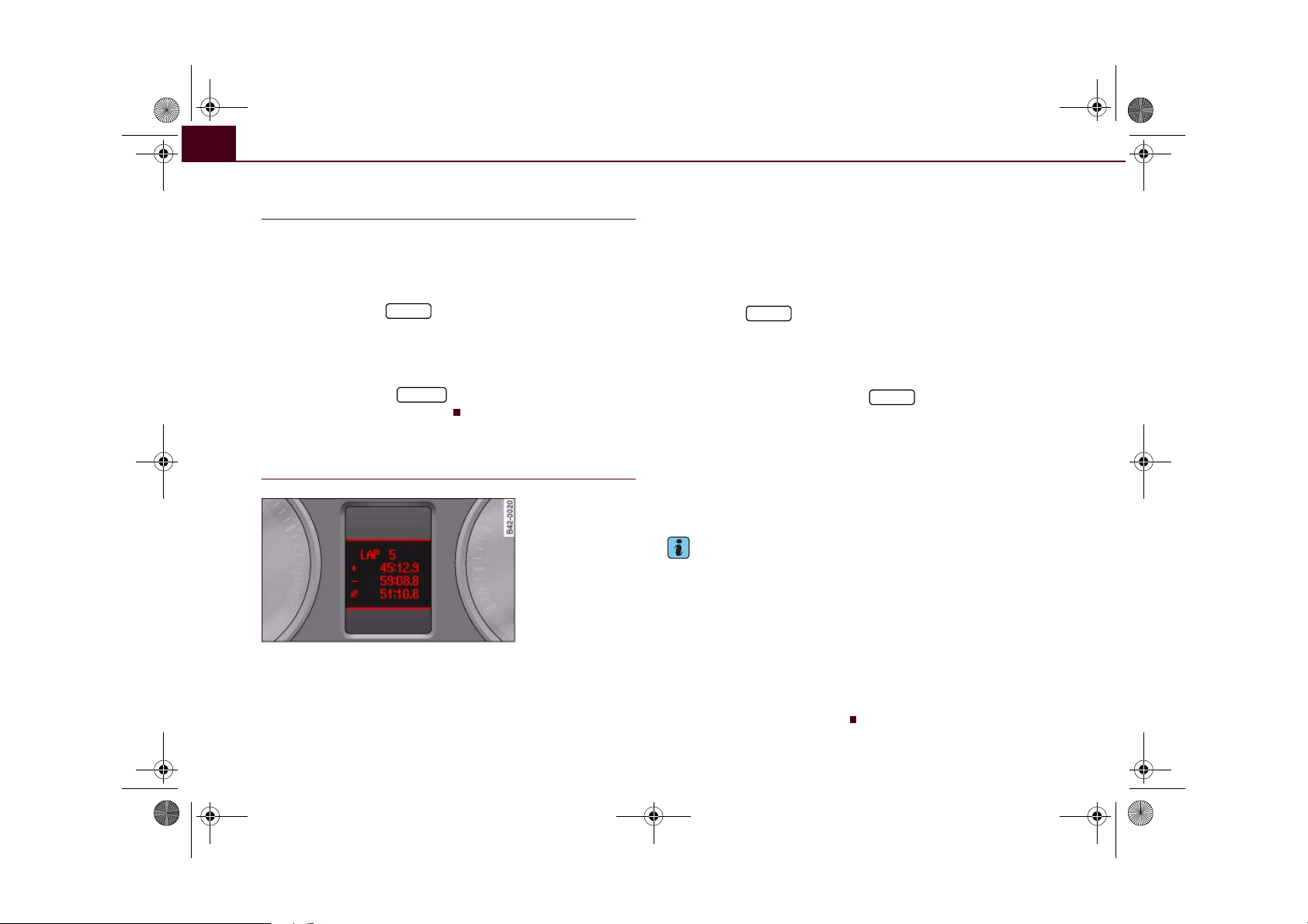
Lap timer
Introduction
The lap timer allows you to record and analyse lap times.
The time (in minutes, seconds and tenths of a second) is shown in
the instrument cluster display. The hour automatically appears in
the display if the session lasts for over an hour. The maximum time
which can be recorded in a single measurement is 99 hours,
59 minutes, 59 seconds and 9/10 of a second. If this time is
exceeded, the lap timer will automatically stop recording and switch
to the pause mode ⇒ page 29.
WARNING
Please direct your full attention to the road at all times! As the
driver, you have full responsibility for the safety of the vehicle and
other road users. For this reason, you should only use the functions in a manner that allows you to maintain control of the
vehicle in all situations - accident risk!
Note
The on-board computer can be used in the normal way while the
stopwatch of the lap timer is running.
Controls Safety Driving tips General maintenance Self-help Technical data
Page 30

A
A
document_0900452a816e6cc9.book Seite 28 Mittwoch, 21. Februar 2007 1:32 13
Driver information system28
Calling up the lap timer
Fig. 21 Controls
Fig. 22 Display: Lap
timer
– With the ignition switched on, keep pressing the
button ⇒ fig. 21 until the lap timer ⇒ fig. 22
B
RESET
appears.
Recording your first lap time
Fig. 23 Display: Lap 1
Fig. 24 Display: Lap 1
recorded; lap 2 started
The current lap appears at the top of the display: e.g. LAP 2
(= second lap).
Starting the lap time
– Press the top part of the rocker switch. Line ⇒ fig. 23
A
shows the current lap time.
Storing the lap time
– Press the top part of the rocker switch again. The time for
the next lap starts simultaneously.
Page 31

A1A
ACA
A
A
A
document_0900452a816e6cc9.book Seite 29 Mittwoch, 21. Februar 2007 1:32 13
Driver information system 29
Each time a lap time is stored, it moves one line up the display
⇒ page 28, fig. 24. The time for the new lap appears in the bottom
2
line .
Recording further lap times
Fig. 25 Display: Lap 2
recorded
Each time you press the top part of the rocker switch when
the lap timer is running, the current lap time is stored and
the next lap time is started simultaneously. Simply repeat
this procedure to record subsequent laps.
The current lap time always appears in the bottom line of the display
⇒ fig. 25.
When you store a lap time, it moves up one line ⇒ fig. 25 from
the bottom of the display. The previous lap time also moves up one
line again . The time for the new lap appears in the bottom line
C
.
A
B
Displaying split times and pausing the lap
timer
The split time (for an intermediate section of a lap, etc.) is
marked with an asterisk.
Fig. 26 Display: Split
time
You can retrieve split times for different sections of the lap.
You can pause the lap timer if you want to take a break
during a session.
Displaying a split time and pausing the lap timer
– Press the bottom part of the rocker switch to display the
split time . The recording of the lap time continues in
C
the background while the split time (marked with an
asterisk) is displayed.
– Press the bottom part of the rocker switch again if you
want to pause the timer. The lap timer is interrupted and
the asterisk in the bottom line disappears.
Resuming recording of lap time
– Press the top part of the rocker switch to resume lap time
recording from the split time or pause mode.
Controls Safety Driving tips General maintenance Self-help Technical data
Page 32
document_0900452a816e6cc9.book Seite 30 Mittwoch, 21. Februar 2007 1:32 13
Driver information system30
Switching the display between lap timer and
on-board computer
You can call up information from the on-board computer
while the stopwatch of the lap timer is running.
Calling up the on-board computer
– Briefly press the button to display the on-board
Reset
computer. You can now use the on-board computer in
the usual way.
Calling up the lap timer
– Keep pressing the button until the lap timer
RESET
⇒ page 28, fig. 22 appears.
Finishing the session and evaluating or
resetting lap times
Fig. 27 Display:
Fastest, slowest and
average lap times
After evaluating the lap times, you can reset the lap timer
data or continue recording further laps ⇒ page 31.
Finishing the lap time session
– When you cross the start/finish line, press the top part of
the rocker switch to store the final lap time. The new lap
time (which always starts simultaneously) will not be
recorded if you now evaluate the lap times.
Evaluating lap times
– Press the button for about two seconds. A
Reset
summary of key lap times appears in the display.
Resetting the lap timer
– While the overall results are shown in the display
⇒ fig. 27, press and hold the button for at least
Reset
two seconds to reset all data of the lap timer to zero.
Overall lap time results
The display will show ⇒ fig. 27:
the fastest lap time
the slowest lap time
Ø the average lap time
Note
• Recorded lap times cannot be deleted individually from the
overall results.
• In addition to the overall results ⇒ fig. 27, the lap timer will only
display the recorded times for the last lap and last lap but one
⇒ page 29, fig. 25.
• The data recorded in the lap timer remain stored after the igni-
tion is switched off.
• The session can be resumed later ⇒ page 31.
• All the data will remain stored in the lap timer unless the driver
deliberately resets the lap timer.
Page 33

document_0900452a816e6cc9.book Seite 31 Mittwoch, 21. Februar 2007 1:32 13
Driver information system 31
Resuming the lap time session later
When you have evaluated the lap times, you can resume the
session and continue recording lap times later.
– Keep pressing the button until the lap timer
Reset
appears ⇒ page 30, fig. 27.
– Press the top part of the rocker switch to start recording
a new lap time.
– To record further lap times, repeat the procedure
described earlier ⇒ page 29, “Recording further lap
times”. To evaluate the overall results, refer to ⇒ page 30,
“Finishing the session and evaluating or resetting lap
times”.
Speed warning function
Applies to vehicles: with speed warning function
Introduction
The speed warning function can help you keep below a
pre-set maximum speed.
The speed warning function will warn you if the vehicle exceeds the
pre-set maximum speed. The system gives an audible warning
signal if the set speed is exceeded by about 10 km/h. A warning
symbol will also appear in the display ⇒ fig. 28.
The speed warning function has two different warning levels*,
which operate independently and serve slightly different purposes:
Speed limit warning 1
With speed limit warning 1, the maximum speed can be changed
while driving. The speed limit that has been set remains stored until
the ignition is switched off.
The speed limit warning symbol for speed warning 1 ⇒ fig. 28
will appear in the display if you exceed the pre-set speed. It goes out
again if the speed is reduced below the set speed limit.
The symbol also goes out if the speed is increased to more than
about 40 km/h above the set speed for at least 10 seconds. However,
this does not cancel the speed limit that was originally set.
Setting speed limit warning 1 ⇒ page 32.
Speed limit warning 2
With speed limit warning 2, the speed limit can only be changed or
cleared when the ignition is switched off. You are recommended to
store this speed limit warning if you always wish to be reminded of
a particular speed limit. This could be when driving in countries
with general speed limits, or if you need to keep below a particular
speed when winter tyres are fitted, etc.
The speed limit warning symbol for speed warning 2 will appear
in the display if you exceed the pre-set speed. Unlike speed limit
warning 1, the warning symbol only goes out once the road speed
has dropped below the stored value again.
Setting speed limit warning 2 ⇒ page 32.
Fig. 28 Display: Speed
warning
Controls Safety Driving tips General maintenance Self-help Technical data
Page 34
A
document_0900452a816e6cc9.book Seite 32 Mittwoch, 21. Februar 2007 1:32 13
Driver information system32
Note
Please bear in mind that, even with the speed warning function, it is
still important to keep a check on the car's speed with the speedometer and to observe the statutory speed limits.
Applies to vehicles: with speed warning function
Setting speed limit warning 1
Speed limit warning 1 is controlled via the adjuster/test
button.
Fig. 29 Detail of the
instrument cluster:
Adjuster/test button
Selecting speed limit
– Drive at the desired maximum speed.
– Press the adjuster/test button ⇒ fig. 29 and hold it down
until the symbol ⇒ page 31, fig. 28 appears.
Clearing speed limit
– Drive the vehicle at a minimum of 5 km/h.
– Press the adjuster/test button for at least two seconds.
The speed warning symbol lights up briefly in the display when
the button is released to confirm that the selected speed has been
stored. The speed limit that has been set remains stored until
another speed is set with a brief push of the button, or until the
memory is cleared with a long push of the button.
Applies to vehicles: with speed warning function
Setting speed limit warning 2
Speed limit warning 2 is set using the switches on the
windscreen wiper lever.
Fig. 30 Controls
Selecting speed limit
– Switch off the ignition.
– Briefly press the adjuster/test button in the instrument
cluster ⇒ fig. 29. The mileage recorder display and the
digital clock will light up.
– Press the adjuster/test button for at least 2 seconds. The
display will show the speed limit which is currently set or,
if no speed limit has been set, the crossed out warning
symbol for speed limit 2.
– To change the speed limit, press the top or bottom of the
function selector switch on the windscreen wiper lever
A
⇒ fig. 30. The speed limit displayed will then increase
or decrease in increments of 10 km/h.
Page 35
A
document_0900452a816e6cc9.book Seite 33 Mittwoch, 21. Februar 2007 1:32 13
Driver information system 33
Clearing speed limit
– Switch off the ignition.
– Briefly press the adjuster/test button in the instrument
cluster ⇒ page 32, fig. 29. The mileage recorder display
and the digital clock will light up.
– Press the adjuster/test button for at least 2 seconds. The
display will show the speed limit which is currently set.
– Now press and hold the button on the wind-
screen wiper lever ⇒ page 32, fig. 30 until the
crossed-out warning symbol for speed limit 2 appears on
the display.
The display lighting for the mileage recorder and digital clock goes
off again a few seconds after the button is released.
Note
This speed limit function can also be operated via the on-board
computer ⇒ page 25, “Selecting options from the menu”.
Reset
B
Notes and symbols
Red symbols
A red symbol warns of a serious malfunction.
–Stop the vehicle.
– Switch off the engine.
– Check the function displayed. Obtain professional assist-
ance if necessary.
Fault in the brake system ⇒ page 35
BRAKE
Coolant level too low / coolant
COOLANT
PRESS.
A red symbol is accompanied by three warning chimes. The symbol
will keep flashing until the fault is corrected. If several faults are
detected at the same time, the symbols are displayed one after the
other for about 2 seconds at a time.
temperature too high
Engine oil pressure too low ⇒ page 36
OIL
Tyre pressure monitoring system*
Note
⇒ page 35
⇒ page 36
• You can press the left adjuster button to display a message that
gives you more information.
• On vehicles equipped with a navigation system the warning
symbol is displayed in the top section of the display while the route
guidance is active.
Yellow symbols
A yellow symbol indicates a malfunction or other item
requiring attention.
Fuel level low ⇒ page 36
Check engine oil level ⇒ page 37
Engine oil sensor defective ⇒ page 37
Controls Safety Driving tips General maintenance Self-help Technical data
Page 36
document_0900452a816e6cc9.book Seite 34 Mittwoch, 21. Februar 2007 1:32 13
Driver information system34
or BRAKE
LIGHT
and
and
Yellow symbols are accompanied by one warning chime. The function indicated should be checked as soon as possible. If several
faults are detected at the same time, the symbols are displayed one
after the other for about 2 seconds at a time.
Brake pads worn ⇒ page 37
Speed warning 1* ⇒ page 37
Speed warning 2* ⇒ page 37
Dynamic headlight range control faulty
Washer fluid level low ⇒ page 37
Battery voltage too high or too
low
Bulb monitor ⇒ page 37
Brake light failure ⇒ page 38
Light sensor/rain sensor (automatic headlights) defective
Selector lever defective*
No R gear*
Clutch overheating* ⇒ page 38
⇒ page 37
⇒ page 37
⇒ page 38
⇒ page 38
Driver messages
Additional messages to assist the driver are displayed in
conjunction with the warning lamps and symbols in the
instrument cluster.
Fig. 31 Detail of the
instrument cluster:
Adjuster/test button
The display will show the appropriate message if the system detects
a bulb failure ⇒ page 37, if the brake pads are worn or you have not
yet selected a gear on a vehicle with R tronic.
The driver can also call up messages in the display for additional
information if a red warning symbol starts flashing.
Calling up driver messages
For example, in the event of an oil pressure malfunction the oil pressure symbol will appear in the display. If you now press the
adjuster/test button ⇒ fig. 31 for at least one second, the following
message will appear in the display:
SWITCH OFF ENGINE AND CHECK OIL LEVEL
The message will disappear from the display after about 5 seconds.
If required, the message can be called up again by briefly pressing
the adjuster/test button.
Page 37
document_0900452a816e6cc9.book Seite 35 Mittwoch, 21. Februar 2007 1:32 13
Driver information system 35
Fault in the brake system
The warning lamp flashes when the handbrake is applied,
or if the brake fluid level is too low or if there is a fault in
the ABS system.
If the symbol flashes in the display when the handbrake
is not applied, there is a fault in the brake system. One of the
following messages will appear in the display together with
the symbol:
Stop vehicle and check brake fluid level
Brake fault ! Drive carefully to nearest workshop
–Stop the vehicle.
– You should obtain professional assistance.
If the ABS fails, the ABS warning lamp will light up together with
the brake warning symbol ⇒ .
Handbrake applied
The warning lamp also lights up when the handbrake is applied.
In addition to this, a warning buzzer will sound after driving for
3 seconds at a speed above 5 km/h.
WARNING
• If the brake fluid level in the reservoir is too low, this could
result in an accident. Do not drive on. You should obtain professional assistance.
• If the brake warning lamp lights up together with the ABS
warning lamp, this can mean that the control function of the ABS
is out of action. As a result the rear wheels can lock relatively
easily when braking. This could cause the tail of the vehicle to skid
sideways. Drive carefully to the nearest qualified workshop and
have the fault rectified.
Fault in the cooling system
Faults in the cooling system must be rectified immediately.
If the symbol flashes in the display, this means that either
the coolant temperature is too high or the coolant level is
too low. The following message will appear in the display
together with the symbol:
Switch off engine, check coolant level
– Stop the vehicle.
– Switch off the engine.
– Check the coolant level ⇒ page 160.
– Add more coolant if necessary ⇒ page 160.
– Wait for the symbol to go out before driving on.
– Obtain professional assistance if necessary.
If the coolant level is correct, the overheating may be caused by a
malfunction of the radiator fan.
If the alternator warning lamp lights up as well ⇒ page 18, it is
possible that the drive belt has broken.
WARNING
• If your vehicle should break down for technical reasons, stop it
at a safe distance away from moving traffic, switch off the engine
and turn on the hazard warning lights ⇒ page 56, “Hazard
warning lights ”.
• Never open the engine lid if you can see or hear steam or
coolant escaping from the engine compartment; there is a risk of
being scalded. Wait until you can no longer see or hear escaping
steam or coolant.
Controls Safety Driving tips General maintenance Self-help Technical data
Page 38

document_0900452a816e6cc9.book Seite 36 Mittwoch, 21. Februar 2007 1:32 13
Driver information system36
WARNING (continued)
• The engine compartment of any motor vehicle is a dangerous
place. Before carrying out any work in the engine compartment,
switch off the engine and allow it to cool down. Please observe the
important safety warnings ⇒ page 155, “Working on components
in the engine compartment”.
Caution
Do not drive on if the symbol has come on to indicate a fault in
the cooling system, otherwise there is a risk of damaging the
engine.
Engine oil pressure too low
If the engine oil pressure is too low the fault must be rectified immediately.
If the symbol flashes in the display, the oil pressure is
too low. The following message will appear in the display
together with the symbol:
Switch off engine and check oil level
– Stop the vehicle.
– Switch off the engine.
– Check the engine oil level ⇒ page 157.
– Obtain professional assistance if necessary.
If the engine oil level is too low
If the engine oil level is too low, add more oil ⇒ page 158.
If the engine oil level is correct
If the symbol flashes and the engine oil level is correct, obtain
professional assistance. Do not drive on. Do not continue to run the
engine, not even at idle speed.
Applies to vehicles: with tyre pressure monitoring system
Tyre pressure monitoring system
The tyre pressure should be corrected as soon as possible
if it is too low.
If the symbol appears, the tyre pressure on at least one
of the wheels is too low. The message Tyre pressures too
low will be displayed.
–Stop the vehicle.
– Check the tyre(s).
– Adjust the tyre pressure ⇒ page 167.
For more detailed information on the tyre pressure monitoring
system please refer to ⇒ page 172.
Fuel level low
When this symbol comes on for the first time, there are about
10 litres of fuel left in the tank. You should fill up as soon as possible
⇒ page 152.
If this warning symbol lights up although the fuel tank is sufficiently
filled, there is a malfunction in the fuel tank system. The display will
also show the driver message Tank system malfunction ! Contact
workshop. Please take the vehicle to a qualified workshop.
Page 39
document_0900452a816e6cc9.book Seite 37 Mittwoch, 21. Februar 2007 1:32 13
Driver information system 37
Check engine oil level
Please check oil level
If the symbol lights up, add 1 litre of oil at the next opportunity
⇒ page 158.
Engine oil sensor defective
If the symbol lights up, take the vehicle to a qualified workshop
and have the oil level sensor checked.
Front brake pads worn
If the symbol lights up, have the front brake pads (and, for
safety's sake the rear pads as well) inspected by a qualified
workshop.
Speed warning 1
If the symbol lights up, this means you are exceeding the speed
that has been pre-set with the speed warning function. You should
reduce your speed accordingly ⇒ page 31.
Speed warning 2
If the symbol lights up, this means you are exceeding the speed
that has been pre-set for speed warning 2. You should reduce your
speed accordingly ⇒ page 31.
Headlight range control defective
This symbol indicates a malfunction in the dynamic headlight
range control. Take the vehicle to a qualified workshop to have the
dynamic headlight range control function repaired.
Washer fluid level low
If the symbol lights up, top up the fluid for the windscreen
washer and headlight washer system ⇒ page 164.
Battery voltage too high or too low
If the symbol lights up, take the vehicle to a qualified workshop
and have the following items checked:
• Poly-V belt
• Battery condition
It is also advisable to check whether the alternator warning lamp
has come on ⇒ page 18.
Bulb monitor
The bulb monitor checks whether the lights on the vehicle
are working.
If a defective bulb is detected, or if one of the lights has failed for
any reason, the bulb monitor symbol will appear in the display
together with an additional message (which goes out after
5 seconds). For instance, if the rear left turn signal is not working,
the display in the instrument cluster will show the following
message:
REAR LEFT TURN SIGNAL
Controls Safety Driving tips General maintenance Self-help Technical data
Page 40
A8A
document_0900452a816e6cc9.book Seite 38 Mittwoch, 21. Februar 2007 1:32 13
Driver information system38
The message disappears after 5 seconds. Press the adjuster/test
button ⇒ page 10, fig. 2 briefly if you wish to call up the message
again.
If the display indicates that one of the lights is not working, this can
have a number of causes:
• Bulb failure ⇒ page 193.
• A “blown” fuse ⇒ page 190, “Changing fuses”.
• Defective electrical wiring.
Have the components replaced or the wiring repaired as necessary
by a qualified workshop.
WARNING
• Bulbs are sensitive to pressure. The glass can break when you
touch the bulb, causing injury.
• Incorrect handling of the high-voltage element of xenon gas-
discharge bulbs can have potentially fatal consequences.
Brake light failure
If the symbol or the text BRAKE LIGHT lights up, check the
following components:
• Brake light bulbs
• Wiring connections
• Brake light switch
Have the components repaired or replaced by a qualified workshop.
Applies to vehicles: with light sensor/ rain sensor
Light sensor/rain sensor
This indicator lamp comes on if the automatic headlights/
automatic wipers are defective.
If the symbol appears, this means that the light sensor/ rain
sensor is not functioning. For safety reasons, the dipped beam
headlights will then be switched on permanently when the light
switch is set to the AUTO position. However, you can still switch the
lights on and off in the normal way with the light switch. If the rain
sensor is defective, the functions operated via the windscreen wiper
lever will still be available. You should have the light sensor/ rain
sensor checked by a qualified workshop as soon as possible.
Applies to vehicles: with R tronic
Selector lever defective and
Selector lever defective! No R gear!
If these symbols light up, there is a fault in the R tronic selector
lever. The indicators on the selector lever will go out or flash. It is no
longer possible to engage reverse gear. If you were using the
gearbox in manual mode, it will switch back to automatic mode.
You can continue to change gear manually. Starting in neutral (N),
pull the paddle lever on the steering wheel to engage first gear.
The gearbox will now remain in manual mode and you can select the
gears using the paddle levers.
You should have the selector lever checked by a qualified workshop
as soon as possible.
+
Note
The brake light switch is only tested during the initial systems check
after starting the engine.
Applies to vehicles: with R tronic
Clutch overheating and
Clutch is overheating ! If possible please stop vehicle.
Page 41
document_0900452a816e6cc9.book Seite 39 Mittwoch, 21. Februar 2007 1:32 13
If these symbols light up, the clutch has overheated and could be
damaged if you continue driving.
Stop the car and obtain professional assistance.
Driver information system 39
Controls Safety Driving tips General maintenance Self-help Technical data
Page 42

A
A
document_0900452a816e6cc9.book Seite 40 Mittwoch, 21. Februar 2007 1:32 13
Doors and windows40
Doors and windows
Remote control keys
Set of keys
Fig. 32 Set of keys
Fi g . 3 3 R em o te c on t ro l
key: Indicator lamp
The set of keys for your vehicle ⇒ fig. 32 includes:
A
two remote control keys
B
one spare key
Remote control key
The remote control key will lock and unlock the car via the central
locking system and start the engine. Press the release button
⇒ fig. 32 (arrow) to make the key spring out of the handle and to fold
it back in.
Spare key
The spare key should be used only temporarily if the remote control
key has been misplaced or lost.
Replacing a key
If one of the keys has been lost, you should take the vehicle to an
Audi R8 dealer to have the remote control coding for that key deactivated. For this purpose you should bring all available keys with
you.
It is also important to notify your insurance company if a key has
been lost.
Checking the key battery level
The indicator lamp ⇒ fig. 33 lights up as soon as you press one of
the buttons. If the indicator lamp does not light up or flash, this
means the battery is exhausted and must be replaced.
Changing the battery ⇒ page 41.
WARNING
• Always switch off the ignition and take the key with you when
leaving the vehicle - even if you only intend to be gone for a short
time. This is especially important if children are left in the car. They
might otherwise be able to start the engine or use power-operated
equipment such as the electric windows - this could lead to injuries.
• Wait for the vehicle to come to a standstill before removing the
ignition key from the lock. Otherwise the steering lock could
engage suddenly, causing an accident.
Page 43
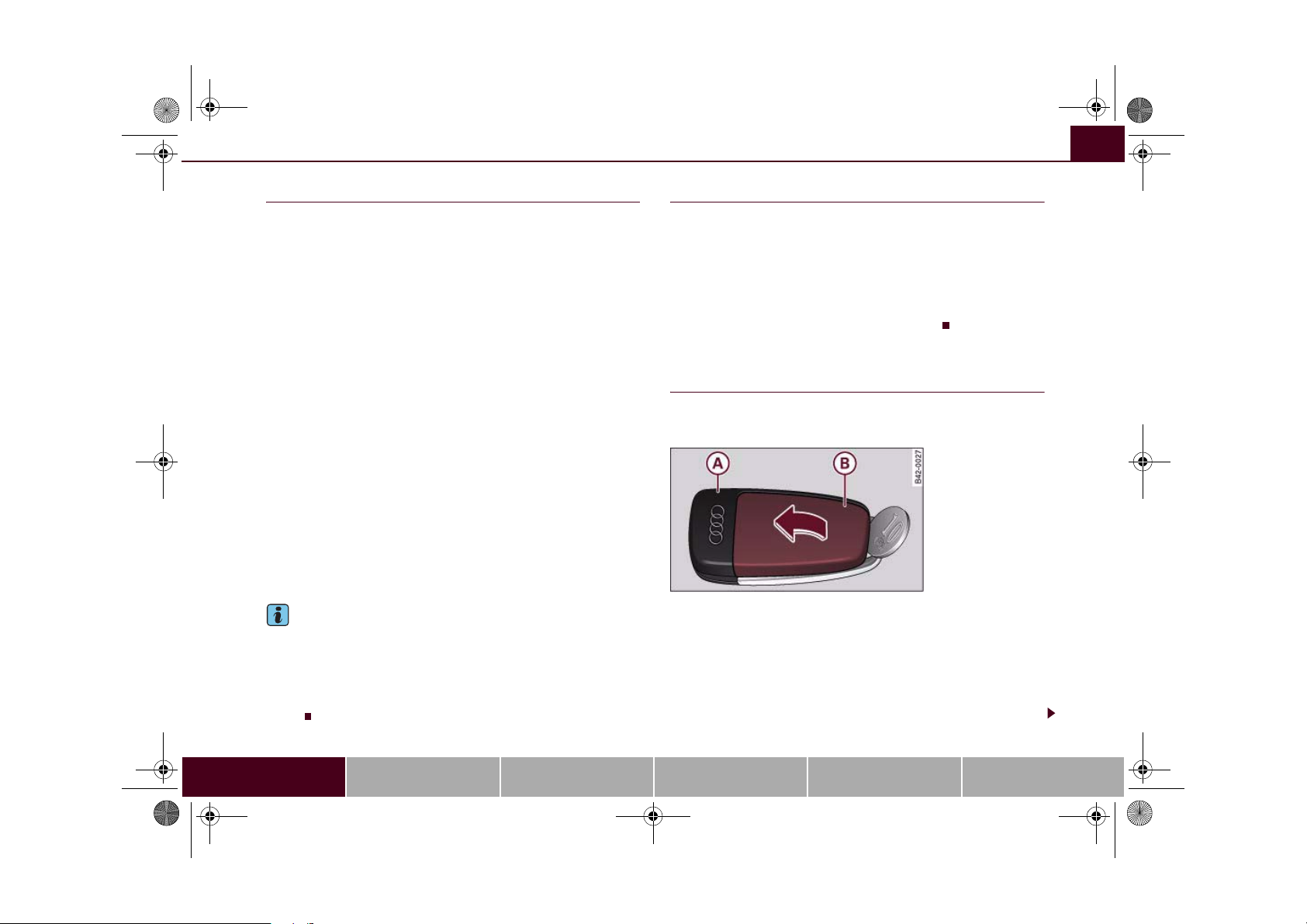
AAA
document_0900452a816e6cc9.book Seite 41 Mittwoch, 21. Februar 2007 1:32 13
Doors and windows 41
Remote control key
The remote control will lock and unlock the vehicle
without having to insert the key in the lock.
The remote control transmitter and the battery are integrated in the
handle of the key. The receiver is in the interior of the vehicle. The
maximum range of the remote control depends on various factors.
The range is reduced when the battery starts to lose power.
If the receiver has been repaired or replaced, or if a replacement key
is used, the system will need re-programming by a qualified workshop. This is necessary so that the receiver can recognise your
remote control key.
The remote control keys (which are radio-operated) conform with all
relevant requirements for Germany and have been approved by the
Federal Approvals Office for Telecommunications of the Federal
Republic of Germany. All components are marked in accordance
with the current legal requirements. This certification forms the
basis for approval for use in other countries.
Personalised remote control key
When you switch off the ignition or lock the vehicle, the settings of
various convenience features are automatically stored and assigned
individually to the remote control key that is currently in use. The
settings stored for the remote control key are then recalled automatically the next time the vehicle is unlocked, the door is opened
or the ignition is switched on.
Note
• The remote control key is automatically deactivated when the
ignition is switched on.
• The function of the remote control key may be impaired by inter-
ference from other nearby radio signals (for example from a mobile
telephone or TV transmitter) if these are in the same frequency
range.
Synchronisation
If the remote control fails to unlock the vehicle, it will be
necessary to re-synchronise the system.
– Press the unlock button on the remote control.
– Use the key to manually unlock the driver's door within
30 seconds.
– Press the unlock
or the lock button .
Replacing the battery for the remote control
key
Each remote control key contains a battery which is
located in the cover of the key.
Fi g . 3 4 R em o te c on t ro l
key: Opening the cover
We recommend having the battery changed by a qualified
workshop if required. However, if you decide to change the
used battery yourself:
– Carefully prise apart the key ⇒ fig. 34 and the cover
B
using a coin.
– Remove cover in the direction of the arrow.
Controls Safety Driving tips General maintenance Self-help Technical data
Page 44

document_0900452a816e6cc9.book Seite 42 Mittwoch, 21. Februar 2007 1:32 13
Doors and windows42
– Take the used battery out of the cover.
– Insert the new battery. Make sure that the “+” symbol on
the battery is facing downwards. The correct polarity is
indicated on the cover.
– After inserting the battery, align the cover and key and
press the two parts together.
For the sake of the environment
Used batteries must be disposed of appropriately and must not be
discarded with ordinary household waste.
Note
The new battery must be of the same type as the original one.
Electronic immobiliser
The immobiliser is designed to prevent unauthorised
persons from driving the vehicle.
An electronic chip inside the key automatically deactivates the
immobiliser when the ignition is switched on. When the ignition is
switched off after coming to a stop the electronic immobiliser is
activated automatically.
If an uncoded key is used, SAFE will appear continuously in the
mileage recorder display.
Note
• The engine can only be started using an original Audi key with
the correct code.
• It may not be possible to start the engine with the key if there is
another ignition key from a different make of vehicle on the same
key ring.
Central locking system
Description
The central locking system allows both doors to be locked
and unlocked simultaneously.
The central locking system on your vehicle locks and unlocks both
doors simultaneously.
The remote control key locks and unlocks the vehicle by means of a
radio signal ⇒ page 43.
Locking and unlocking the vehicle using the key
In addition to the other functions, you can lock and unlock the
vehicle in the normal way by turning the key in the driver's door lock.
However, please note that when you unlock the vehicle with the key,
this only unlocks the mechanical lock on the doors set in the menu
display ⇒ page 24. In order to switch off the anti-theft alarm, you
must insert the key in the ignition lock and switch on the ignition
within 15 seconds after opening the driver's door. The alarm will be
set off if the ignition is not switched on within 15 seconds.
When you lock the vehicle, this automatically locks both of the doors
and activates the anti-theft alarm.
Windows
The windows can be opened or closed together via the central
locking system ⇒ page 43.
Deadlock mechanism
The central locking system is combined with a deadlock mechanism. Once the vehicle has been locked from the outside, the door
handles on the inside are deactivated. This makes it more difficult
to break into the vehicle.
However, it is also possible to lock the vehicle without activating the
deadlock mechanism.
Page 45

AAABACAAA
document_0900452a816e6cc9.book Seite 43 Mittwoch, 21. Februar 2007 1:32 13
Doors and windows 43
Driver's door lock: Turn the key in the driver's door to the “lock” position twice within 2 seconds.
Automatic locking function (Auto Lock)
The Auto Lock function locks all the doors and the luggage lid when
the vehicle exceeds a speed of about 15 km/h.
The vehicle is unlocked again automatically when the ignition key is
removed. Alternatively, the vehicle can also be unlocked via the
central locking switch or by pulling one of the inside door
handles. If desired, you can deactivate the Auto Lock feature in the
menu display ⇒ page 24 or have it deactivated by a qualified workshop.
Turn signals
All the turn signals will flash as confirmation when the vehicle is
locked or unlocked. The turn signals flash twice when the vehicle is
unlocked and once when the vehicle is locked, provided that the
luggage lid and all the doors are closed. In addition, the interior
lights will automatically light up when the vehicle is unlocked and
go out when the vehicle is locked, provided that the switches are in
the courtesy light position.
WARNING
Do not leave anyone (especially children) in the car if it is locked
from the outside and the deadlock mechanism is activated: the
doors and windows cannot then be opened from the inside.
Locked doors could delay assistance in an emergency, potentially
putting lives at risk.
• Never leave any valuable items in the vehicle unattended. Even a
locked vehicle is not a safe.
Locking and unlocking the vehicle
Fi g . 3 5 R em o te c on t ro l
key: Control buttons
Unlocking the vehicle
– Press button once ⇒ fig. 35.
Locking the vehicle
– Press button once ⇒ .
Unlocking the luggage lid
– Press button for at least one second.
Opening all the windows
– Press and hold button until all windows are open.
Note
• If the central locking system should fail to work, you can still lock
and unlock the driver's door with the key. The passenger's door can
be locked manually ⇒ page 46.
• The deadlock mechanism and the anti-theft alarm cannot be acti-
vated if the central locking is not functioning.
Controls Safety Driving tips General maintenance Self-help Technical data
Closing all the windows
– Press and hold button until all windows are closed
⇒ .
The turn signals will flash twice as confirmation when you unlock
the car. The vehicle will be locked again automatically if you do not
B
Page 46

A
AAABA
document_0900452a816e6cc9.book Seite 44 Mittwoch, 21. Februar 2007 1:32 13
Doors and windows44
open one of the doors or the luggage lid within 30 seconds after
unlocking the car. This function prevents the vehicle from remaining
unlocked if the unlocking button is pressed by mistake.
On vehicles with the security central locking feature, you can unlock
just the driver's door by pressing button once, or the whole
vehicle by pressing the button twice.
The turn signals flash once when the vehicle is locked to confirm
that the doors and luggage lid are properly locked.
A
WARNING
• Do not leave anyone (especially childr en) in th e c ar if it is l oc ked
from the outside and the deadlock mechanism is activated: the
doors and windows cannot then be opened from the inside.
Locked doors could delay assistance in an emergency, potentially
putting lives at risk.
• Take care when closing the windows. Careless use of the
windows can cause injuries.
• For safety reasons, you should only use the remote control
open and close functions within about 2 metres of the vehicle. To
avoid injuries, always keep an eye on the windows when pressing
the button to close them. The windows stop moving as soon as
the button is released.
Note
• The remote control should only be used when the doors and the
front lid are closed.
• The remote control should not be used when the vehicle is out of
sight.
• The anti-theft alarm can be accidentally activated and the vehicle
locked if you press the locking button on the remote control inside
the vehicle before inserting the key in the ignition. If this should
happen by mistake, press the unlocking button .
• The convenience open/close function for the windows only
works when the “Convenience open” function is activated in the
menu display ⇒ page 24.
Locking and unlocking the vehicle using the
key
If the central locking system should fail to operate, the
vehicle can still be locked and unlocked by turning the key
in the lock.
Fig. 36 Lock on
driver's door
Unlocking
– Turn the key in the driver's door lock to position
⇒ fig. 36.
Locking
– Turn the key in the driver's door lock once to position
⇒ .
– If you turn the key to position in the driver's door lock
a second time within 2 seconds, this will lock the vehicle
without activating the deadlock mechanism.
B
Page 47

document_0900452a816e6cc9.book Seite 45 Mittwoch, 21. Februar 2007 1:32 13
Doors and windows 45
WARNING
Do not leave anyone (especially children) in the car if it is locked
from the outside and the deadlock mechanism is activated: the
doors and windows cannot then be opened from the inside.
Locked doors could delay assistance in an emergency, potentially
putting lives at risk.
Note
• The deadlock mechanism and the anti-theft alarm cannot be acti-
vated if the central locking is not functioning.
• However, please note that when you unlock the vehicle with the
key, this only unlocks the mechanical lock on the doors set in the
menu display ⇒ page 24.
• Both doors are automatically locked when you lock the vehicle.
Central locking switch
The central locking system can be activated using the
central locking switch on the driver's door.
Unlocking the vehicle
– Press the lower switch
Please note the following when you use the central locking switch
to lock your vehicle:
.
• It is not possible to open the doors from the outside (for safety
reasons, e.g. when stopped at traffic lights).
• The LED in the central locking switch lights up when all the doors
and the luggage lid are closed and locked.
• You can open the doors individually from the inside by pulling
the inside door handle.
• When the driver's door is open, it cannot be locked by pressing
the central locking switch and then closing the door. This helps to
prevent you from being locked out of the vehicle. The door has to be
locked separately after it has been closed.
• In the event of an accident in which the airbags inflate, doors
locked from the inside will be automatically unlocked to facilitate
access and assistance.
WARNING
The central locking switch is still operative when the ignition is
switched off. You can use it to lock both doors automatically.
However, since this makes it difficult to enter the car from the
outside, you should never leave children unattended in the vehicle.
Locked doors could delay assistance in an emergency, potentially
putting lives at risk.
Fig. 37 Detail of the
driver's door: Central
locking switch
Note
The central locking switch inside the vehicle will not be operative if
the deadlock mechanism has been activated.
Locking the vehicle
– Press the upper switch
Controls Safety Driving tips General maintenance Self-help Technical data
⇒ fig. 37 ⇒ .
Page 48
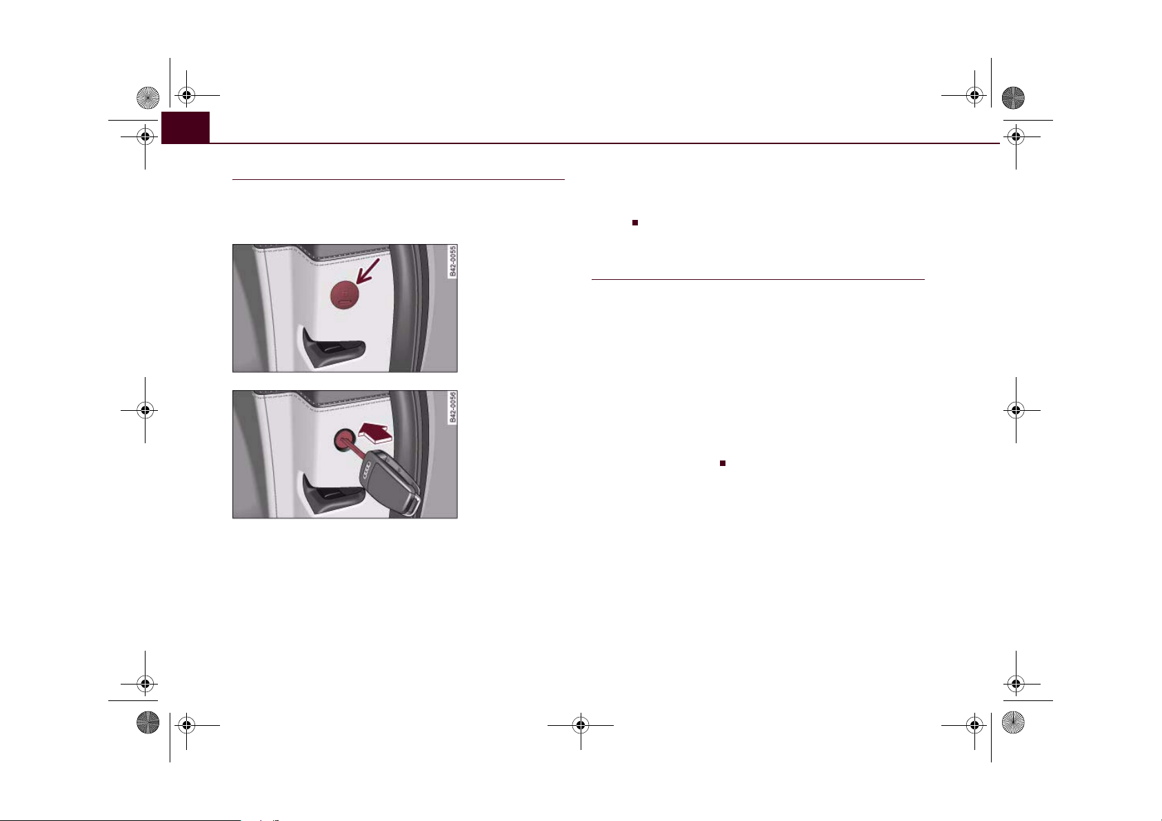
document_0900452a816e6cc9.book Seite 46 Mittwoch, 21. Februar 2007 1:32 13
Doors and windows46
Locking passenger's door manually
If the central locking system should fail to work at any
time, the passenger's door will have to be locked separately.
Fig. 38 Manual locking
device on the
passenger's door pillar
Fig. 39 Locking the
door manually
For this purpose, a manual locking device (only visible when
the door is open) is provided on the passenger's door.
–Open the door.
– Pull the cap out of the opening ⇒ fig. 38.
– Insert the key in the slot inside ⇒ fig. 39 and turn it to the
right as far as the stop.
–Replace the cap.
Once the door has been closed it can no longer be opened from the
outside. The door can be opened from the inside by pulling the door
handle.
Applies to vehicles: with security central locking
Security central locking
The security central locking feature allows the driver's
door to be unlocked separately, without unlocking other
areas.
Unlocking the driver's door
– Turn the key to the unlock position once.
Unlocking both doors at the same time
– Turn the key to the unlock position twice within 5
seconds.
The deadlock mechanism is immediately deactivated even if just the
driver's door is unlocked.
Page 49
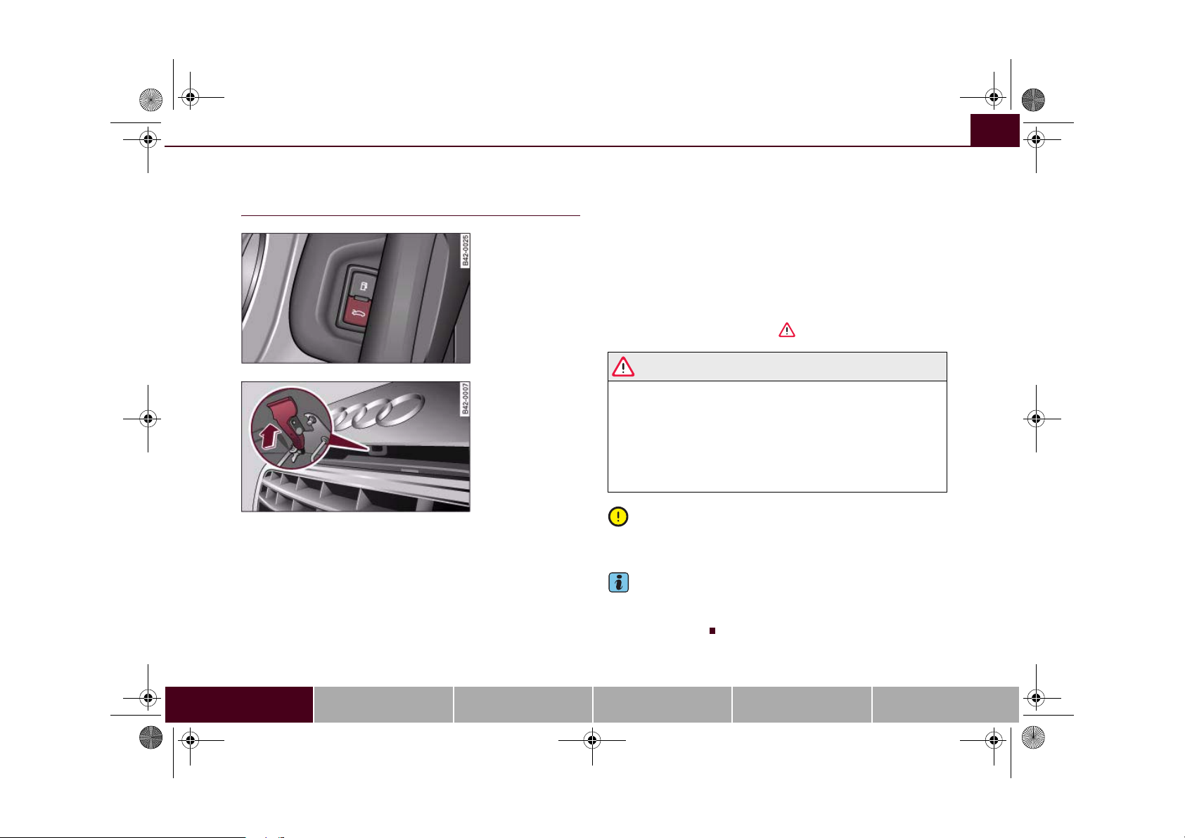
document_0900452a816e6cc9.book Seite 47 Mittwoch, 21. Februar 2007 1:32 13
Doors and windows 47
Luggage lid
Opening and closing the luggage lid
Fig. 40 Driver's door:
Unlocking the luggage
lid
Fig. 41 Luggage lid
unlocked: Release lever
The windscreen wipers must be switched off and the wiper
arms must be in contact with the windscreen when the
luggage lid is opened. Otherwise the paint may get
damaged.
Opening luggage lid
– Press the centre button on the remote control key, or
– Press the unlock switch on the driver's door ⇒ fig. 40.
– Pull the release lever ⇒ fig. 41 in the direction indicated
(arrow). This will release the arrester hook.
– Pull the luggage lid up.
Closing luggage lid
– To close the luggage lid, pull it down to overcome the
spring pressure.
– Close the luggage lid.
– Press down the luggage lid carefully with both hands
until you hear it engage ⇒ .
WARNING
• For safety reasons the luggage lid must always be completely
closed when the vehicle is moving. After closing it always check
that it is properly secured. The luggage lid must be flush with the
adjacent body panels.
• Should you notice that the luggage lid is not safely secured
when the vehicle is moving, stop the vehicle immediately and
close the luggage lid properly, otherwise it could cause an accident.
Caution
Make sure that no objects protrude beyond the edges of the storage
well otherwise the luggage lid could be damaged.
Note
The door catches/luggage lid warning symbol lights up in the instrument cluster if the luggage lid is not properly closed when the ignition is switched on.
Controls Safety Driving tips General maintenance Self-help Technical data
Page 50
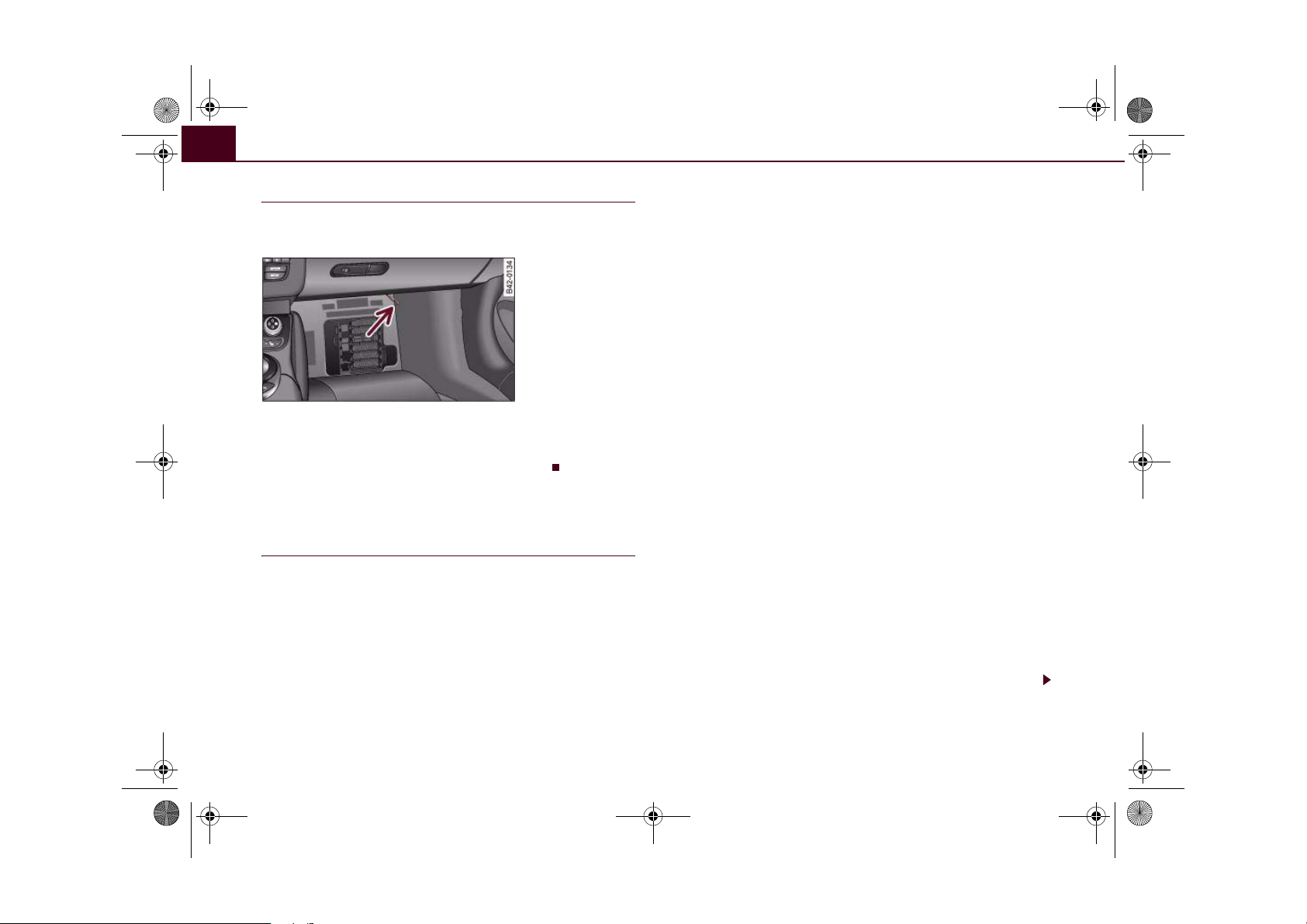
document_0900452a816e6cc9.book Seite 48 Mittwoch, 21. Februar 2007 1:32 13
Doors and windows48
Manual release of the luggage lid
The luggage lid can be released manually if it will not
open in the normal way.
Fig. 42 Detail: Manual
release
– Fold out the foot rest in the passenger's footwell
⇒ page 190.
– Pull the plastic cord towards you ⇒ fig. 42.
Anti-theft alarm system
Description
The anti-theft alarm triggers an alarm if anyone attempts
to break into the vehicle.
The anti-theft alarm helps to prevent the vehicle being broken into
or stolen. If the system senses interference with the vehicle it triggers an audible and visible alarm.
How is the system switched on (armed)?
The anti-theft alarm system switches on automatically when the
vehicle is locked with the remote control or by turning the key in the
driver's door (if the door is closed). The system becomes active
about 30 seconds after the vehicle is locked.
If you turn the key twice to the lock position within one second, the
anti-theft warning system is not activated.
How is the system switched off?
The anti-theft alarm is only switched off when the vehicle is
unlocked using the remote control. The vehicle will lock itself again
automatically if none of the doors is opened within 60 seconds after
pressing the remote control button.
If the vehicle is opened with the key on the driver side door, the
passenger side door remains locked. The anti-theft alarm is only
switched off if the key is inserted into the ignition lock within 15
seconds and the ignition is switched on. Otherwise the system trig-
gers the alarm. On some export versions the alarm is already triggered as soon as the driver's door is unlocked with the key and
opened.
When does the system trigger an alarm?
The anti-theft alarm monitors and protects the following parts of
the car:
• Engine compartment (engine lid)
• Luggage compartment
• Doors
• Ignition
• Interior ⇒ page 49
If any of the named areas are entered or tampered with, the alarm
will sound.
How is the alarm switched off?
The alarm can be switched off by unlocking the vehicle using the
remote control, or by switching on the ignition with the key and thus
“disarming” the system. The alarm will also switch itself off when it
comes to the end of its cycle.
Page 51
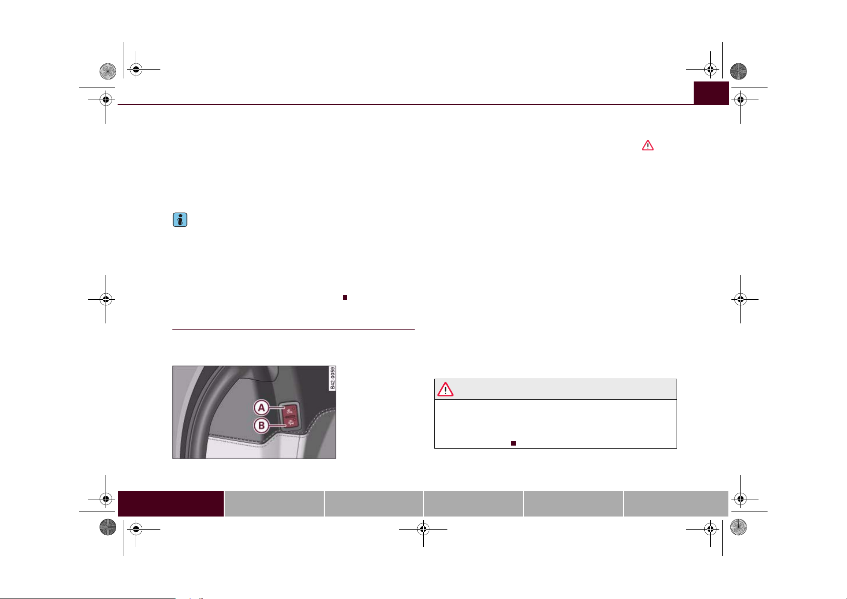
A
A
document_0900452a816e6cc9.book Seite 49 Mittwoch, 21. Februar 2007 1:32 13
Doors and windows 49
Turn signals
The turn signals flash briefly when the vehicle is locked to confirm
that the doors, the engine lid and the luggage lid are properly
closed and locked.
If the turn signals do not flash, check the doors, engine lid and
luggage lid to make sure they are properly closed. The turn signals
will flash briefly if one of the doors, the luggage lid or the engine lid
is closed after the system has been switched on.
Note
• To make sure that the alarm is fully operative when leaving the
vehicle, briefly check that all the doors and windows are closed.
• If the vehicle is unlocked at the driver's door using the key, the
central locking switch only becomes fully functional after the ignition is switched on.
• The alarm is triggered immediately if one of the battery cables is
disconnected while the alarm system is active.
Interior monitor
The interior monitor triggers an alarm if it detects movement inside the vehicle.
Fig. 43 Switches for
the interior monitor in
the door trim (only
visible when the
driver's door is open)
You should deactivate the interior monitor if there is a
possibility that the alarm could be set off, for instance, by a
pet or by an object moving about inside the car ⇒ . The
tow-away protection function* should be deactivated if the
car is being towed or transported (for instance by rail or
ship).
Deactivating interior monitor
– Press the switch on the door ⇒ fig. 43.
A
– Then lock the vehicle.
Deactivating the tow-away protection*
– Press the switch on the door.
B
– Then lock the vehicle.
The diode in the switch or will light up when the interior
monitor / tow-away protection* function is deactivated. In addition,
the diode on the dashboard will light up for about 3 seconds. The
diode on the dashboard will flash rapidly for about 3 seconds after
the vehicle is locked. There then follows an interval of about 30
seconds before the diode starts flashing slowly.
The interior monitor / tow-away protection* function is automatically switched on again next time the vehicle is locked.
WARNING
Do not leave anyone (especially children) in the car if it is locked
from the outside and the deadlock mechanism is activated: the
doors and windows cannot then be opened from the inside.
Locked doors could delay assistance in an emergency, potentially
putting lives at risk.
Controls Safety Driving tips General maintenance Self-help Technical data
Page 52
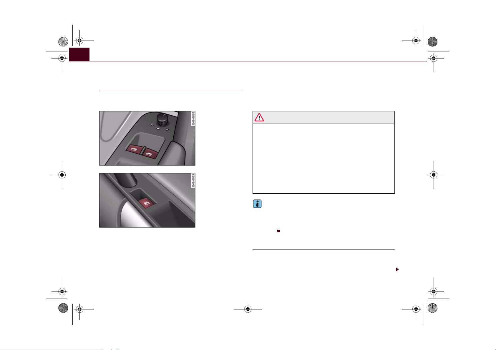
document_0900452a816e6cc9.book Seite 50 Mittwoch, 21. Februar 2007 1:32 13
Doors and windows50
Electric windows
Controls
The driver can operate all the electric windows in the
vehicle.
Fig. 44 Detail of the
driver's door: Controls
Fig. 45 Switch on front
passenger's door
The electric windows are controlled by two-stage switches:
Opening the windows
– Press the switch as far as the first stop and hold it until
the window has moved to the desired position.
– Press the switch briefly to the second stop: the window
will automatically open all the way.
Closing the windows
– Pull the switch as far as the first stop and hold it until the
window has moved to the desired position.
– Pull the switch briefly to the second stop: the window will
automatically close all the way.
WARNING
• Always take the key with you when leaving the vehicle - even if
you only intend to be gone for a short time. This is especially
important if children are left in the car. They might otherwise be
able to start the engine or use power-operated equipment such as
the electric windows - this could lead to injuries. The window
switches are only deactivated when the driver's door or the front
passenger's door is opened.
• Always be careful when closing the windows. Careless use of
the electric windows can cause severe injuries.
• When locking the vehicle from the outside, make sure that
nobody is inside the vehicle, as the windows cannot be opened
from the inside in an emergency.
Note
• When the doors are opened the windows will automatically
come down approximately 10 mm.
• You can also open the windows using the remote control key
⇒ page 43.
Possible malfunctions
The one-touch open and close function will not work if the battery
has been temporarily disconnected. The function can be restored as
follows:
Page 53

document_0900452a816e6cc9.book Seite 51 Mittwoch, 21. Februar 2007 1:32 13
• Close the window as far as it will go by lifting and holding the
window switch.
• Release the switch and then lift it again for one second. This will
reactivate the automatic function.
Doors and windows 51
Controls Safety Driving tips General maintenance Self-help Technical data
Page 54
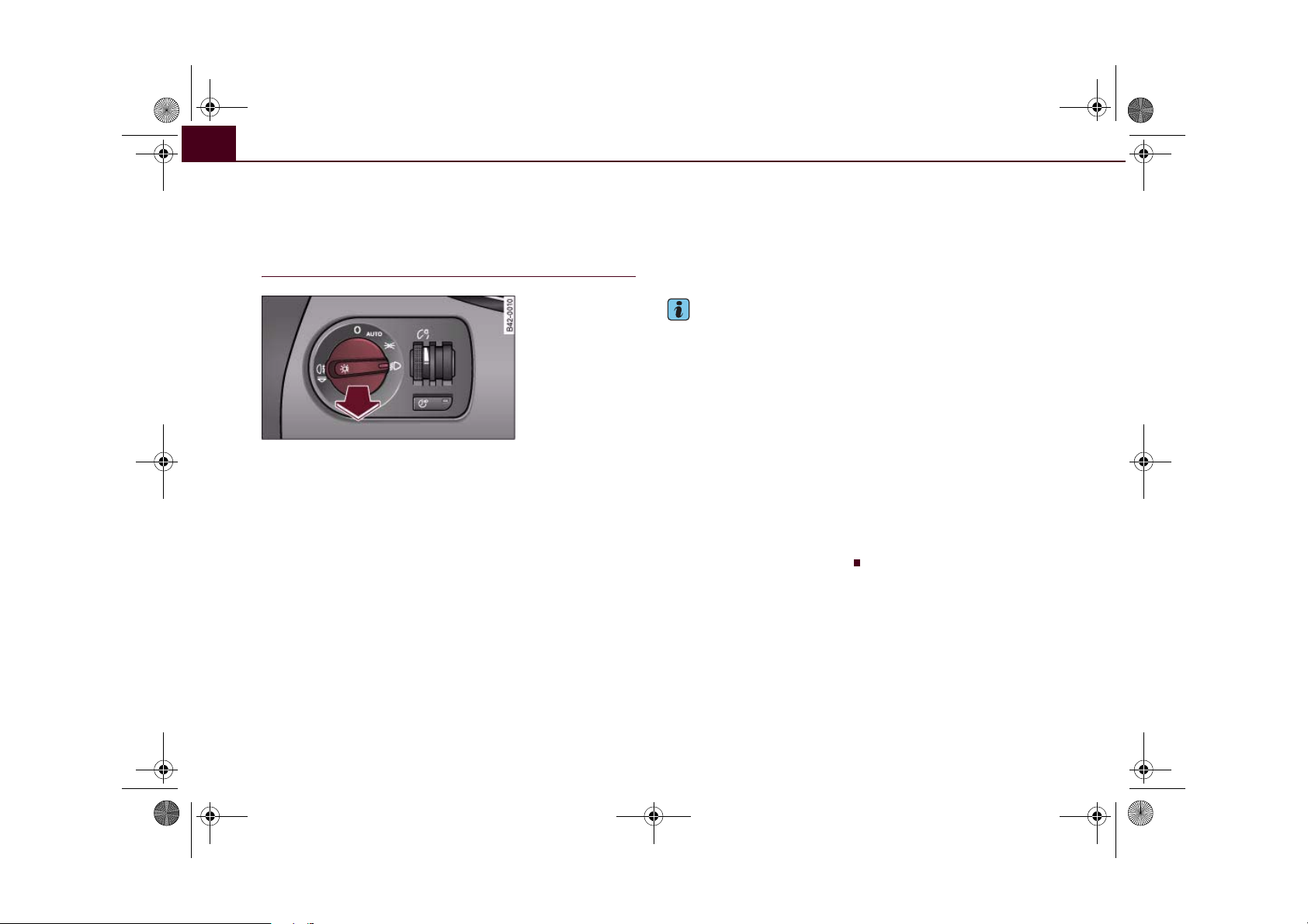
document_0900452a816e6cc9.book Seite 52 Mittwoch, 21. Februar 2007 1:32 13
Lights and vision52
Lights and vision
Lights
Switching lights on and off
Fig. 46 Detail of the
dashboard: Light
switch
Switching on the side lights
– Turn the light switch ⇒ fig. 46 to position
cator lamp
lights up when the side lights are on.
Switching on the dipped or main beam
headlights
– Turn the light switch to position
.
– Press the main beam lever forward ⇒ page 56.
Switching off the lights
– Turn the light switch to position O.
The dipped beam headlights will only work with the ignition on. The
headlights are switched to side lights while the engine is being
started and after the ignition has been switched off.
. The indi-
The daytime running lights are activated when you switch on the
ignition if the light switch is in position 0 or AUTO, provided that the
daytime running lights function has been activated in the menu
display ⇒ page 24.
Note
• If the lights are left on after the key has been taken out of the
ignition lock, a buzzer sounds when the driver's door is opened.
• The use of the lighting described here is subject to the relevant
statutory requirements.
• The headlights and rear lights may mist up temporarily on the
inside in cool or damp weather.
− This is due to the difference in temperature on the inside and
the outside of the headlight glass.
− When the headlights are switched on the surface heated by
the light will soon be demisted, however the glass may still be
misted up inside, around the edges.
− This phenomenon has no influence on the life expectancy of
the vehicle lights.
• Switch on the headlights when the ambient light starts to fade
or in conditions of poor visibility.
Page 55
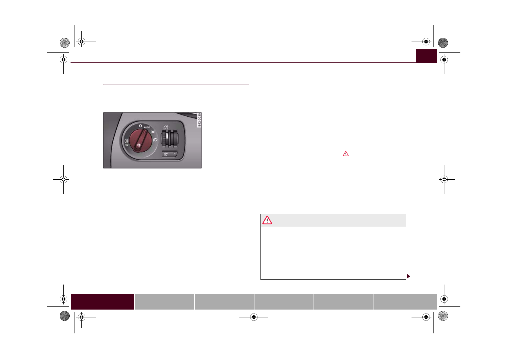
document_0900452a816e6cc9.book Seite 53 Mittwoch, 21. Februar 2007 1:32 13
Lights and vision 53
Applies to vehicles: with automatic headlights
Automatic (sensor-controlled) headlights
If you set the switch to “AUTO”, the headlights will come
on and switch off automatically according to the ambient
light level.
Fig. 47 Detail of the
dashboard: Light
switch
The automatic headlight setting only activates the dipped
beam headlights (not the main beam headlights)
⇒ page 52.
Activating automatic headlights
– Turn the light switch ⇒ fig. 47 to the AUTO position.
Deactivating automatic headlights
– Turn the light switch to position O.
The symbol in the switch lights up when the switch is in the AUTO
position.
The dipped beams, side lights, rear lights and number plate lights
come on together when the headlights are switched on automatically.
When you are using the automatic headlights you can also operate
the main beam headlights, however, please note the following: If
you activate the main beam headlights while using the automatic
headlights function (e.g. when driving through a tunnel), but do not
deactivate them again, only the dipped beam headlights will come
on the next time the lights are automatically switched on. To be able
to use the main beam headlights again you must first pull the main
beam lever back to the "off" position and then push it forward again
to "on".
The side lights, headlights and rear fog light can still be switched on
manually in the normal way by using the light switch ⇒ page 52.
Sensors in the mounting for the interior mirror monitor the ambient
light level. The headlights will be switched on automatically if the
available light drops below a preset value (for instance when driving
through a tunnel, etc.). The headlights switch off again automatically when the light level increases ⇒ .
Malfunction of light sensor
If a malfunction should occur in the light sensor, the symbol will
light up in the display. For safety reasons, the dipped beam headlights will then be switched on permanently when the light switch
is set to the AUTO position. However, you can still switch the lights
on and off in the normal way with the light switch. You should have
the light sensor checked by a qualified workshop as soon as
possible.
WARNING
• The automatic headlights are only intended to assist the driver.
The driver must always ensure that the headlights are used when
required, and may have to switch them on manually when the light
conditions or visibility are poor. The light sensors are, for example,
not able to detect rain and fog - you should therefore always
switch on the headlights in these conditions and when driving
after dark.
• Observe all relevant statutory requirements when using the
lighting systems described here.
Controls Safety Driving tips General maintenance Self-help Technical data
Page 56
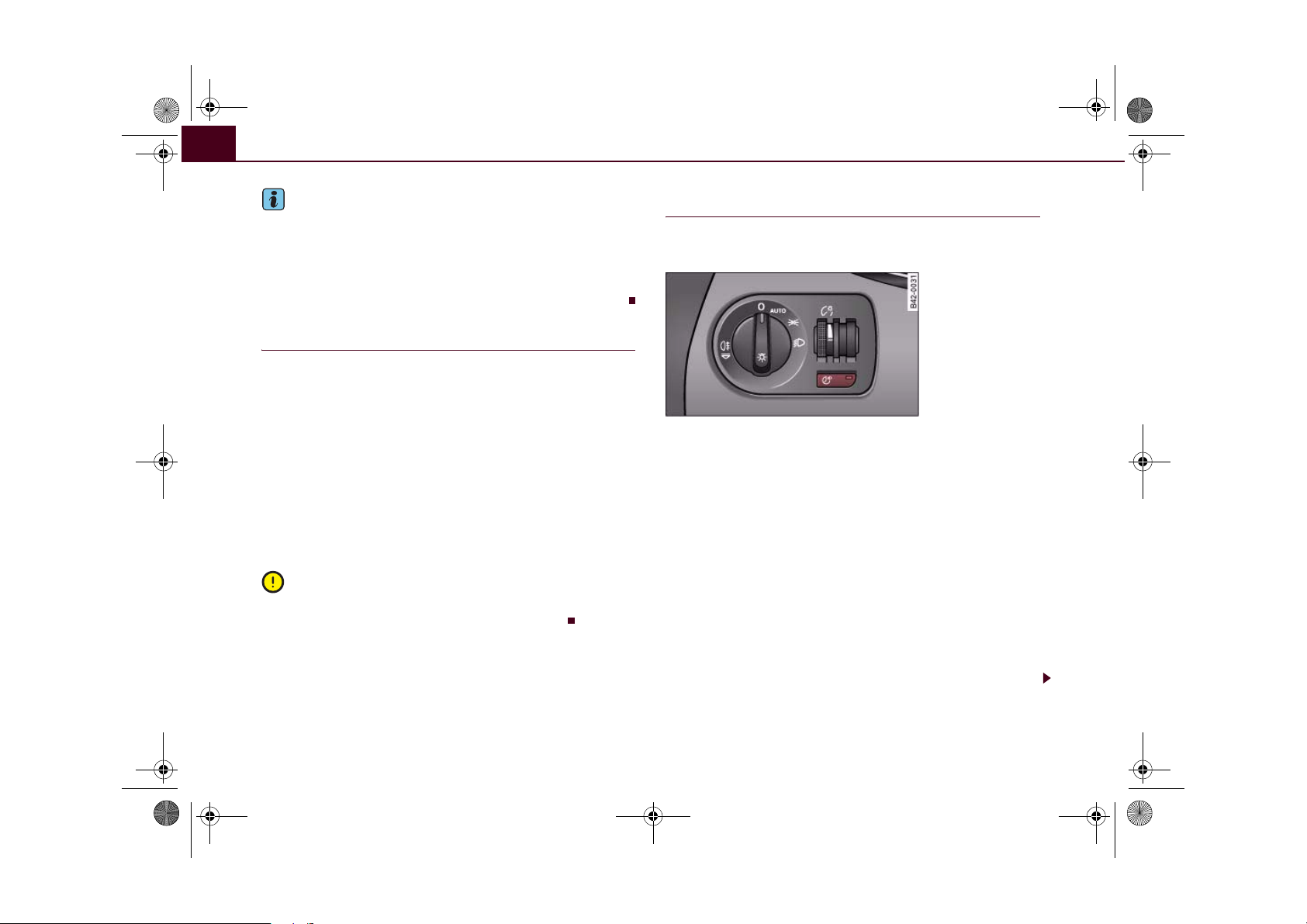
document_0900452a816e6cc9.book Seite 54 Mittwoch, 21. Februar 2007 1:32 13
Lights and vision54
Note
• When the automatic headlights have been activated, the dipped-
beam headlights will go out when the ignition is switched off, and
the side lights will go out when the key is taken out.
• Do not attach any stickers to the windscreen in front of the
sensor, as this would interfere with the operation of the automatic
headlights and the automatic anti-dazzle function for the mirrors.
Rear fog light
The light switch can also be used to turn on the rear fog
light.
– Do not turn the light switch ⇒ page 52, fig. 46 to the
symbol
– First turn the light switch
tion
– Then pull out the light switch to switch on the rear fog
light.
The s ymbol next to the switch will light up when the rear fog light
is on.
To avoid dazzling the traffic behind you, the rear fog light should
only be used in accordance with statutory regulations.
.
⇒ page 52, fig. 46 to posi-
.
Caution
Applies to vehicles: with coming home/leaving home function
Coming home/leaving home function
After dark the area around the car is lit up with the aid of
the coming home / leaving home function.
Fig. 48 Detail of the
dashboard: Coming
home / leaving home
switch
Activating the functions
– Press the button
button.
Deactivating the functions
– Press the button
The coming home / leaving home function is controlled by light
sensors in the mounting for the rear view mirror. The system will
function when the following requirements are met:
⇒ fig. 48. The diode will be lit in the
. The diode in the button will go off.
• The diode in the button is lit .
• The headlights and the ignition are switched off.
• Dark conditions; the sensors register little or no light.
• The leaving home function is activated in the menu display
⇒ page 24.
Page 57

document_0900452a816e6cc9.book Seite 55 Mittwoch, 21. Februar 2007 1:32 13
Lights and vision 55
Coming home function
When the system is activated and it is dark, the coming home function will illuminate the vehicle and its surroundings by switching on
the dipped headlights, rear lights, engine compartment lighting*
and number plate lights when the driver's door is opened.
The dipped headlights will stay on for about four minutes as long as
one of the doors or the luggage lid is open.
The dipped headlights stay on for about 30 seconds to light up the
area in front of the car after all the doors and the luggage lid have
been closed.
If required, you can set the time interval to between 0 and 60
seconds in the driver information system (Lights menu) ⇒ page 24.
Leaving home function
The dipped headlights and the engine compartment lighting* are
switched on when the vehicle is unlocked with the button on the
remote control key if the leaving home function is activated in the
menu display ⇒ page 24.
The dipped headlights and the engine compartment lighting*
switch off when the driver's door is opened. If the driver's door is not
opened, the dipped headlights and the engine compartment
lighting* will be switched off when the car automatically locks again
⇒ page 41.
Note
• If you always wish to use the coming home / leaving home func-
tion, you can leave it switched on permanently. As the system is
controlled via a light sensor, it will only work in dark conditions.
• Permanent use of the coming home / leaving home function, in
particular on short journeys, will increase the load on the battery. To
make sure the battery is always sufficiently charged, occasionally
drive longer distances.
• Observe all relevant statutory requirements when using the
lighting systems described here.
Instrument lighting
The brightness of the instrument lighting, displays and
centre console lighting can be varied as required.
Fig. 49 Instrument
lighting
The basic level of brightness for the instrument lighting is
adjusted using the left-hand thumbwheel
The lighting of the needles in the instrument dials is regulated by a
photo-transistor integrated in the instrument cluster. When the
vehicle's lights are switched on, the illumination of the centre
console and instruments (needles and dials) is automatically
adjusted according to the prevailing light conditions. The driver can
also vary the brightness of the illumination manually if required:
With the ignition switched on
When the ignition is on, the basic level of brightness of the needles
in the instrument cluster can be adjusted by turning the thumbwheel.
With the vehicle's lights switched on:
When the vehicle's lights are switched on, the brightness of the
instrument lighting, displays and centre console lighting can be
varied by turning the thumbwheel.
⇒ fig. 49.
Controls Safety Driving tips General maintenance Self-help Technical data
Page 58

document_0900452a816e6cc9.book Seite 56 Mittwoch, 21. Februar 2007 1:32 13
Lights and vision56
Hazard warning lights
The hazard warning lights are used to make other road
users aware of your vehicle in hazardous situations.
Fig. 50 Cen tre console:
Switch for hazard
warning lights
– Press the switch to switch the hazard warning lights
on or off ⇒ fig. 50.
All four turn signals flash simultaneously when the hazard warning
lights are switched on. The two turn signal indicator lamps and
the indicator lamp in the switch will flash at the same time. The
hazard warning lights also work when the ignition is switched off.
In an accident in which the airbags are activated, the hazard
warning lights are switched on automatically.
Note
You should switch on the hazard warning lights to warn other road
users, for instance:
• When reaching the tail end of a traffic jam
• If your vehicle breaks down or there is an emergency
• If your vehicle is being towed away, or if you are towing another
vehicle.
Turn signal and main beam lever
The turn signal and main beam lever also operates the
parking lights and the headlight flasher.
Fig. 51 Turn signal and
main beam headlight
lever
The turn signal and main beam headlight lever has the
following functions:
Turn signals
– Move the lever all the way up ⇒ fig. 51 to indicate right,
or all the way down to indicate left.
– Move the lever up or down to the point of resistance and
hold it there to signal briefly, for instance when changing
lane.
– Move the lever briefly up or down as far as the point of
resistance and release it to signal three times with the
turn signals. This one-touch signalling function must be
activated in the menu display ⇒ page 24.
Main beam headlights
– Press the lever forward to switch on the main beams.
– Pull the lever back towards you to switch the main beam
headlights off again.
Page 59

AAAAA
document_0900452a816e6cc9.book Seite 57 Mittwoch, 21. Februar 2007 1:32 13
Lights and vision 57
Headlight flasher
– Pull the lever towards the steering wheel to operate the
flasher.
Parking lights
– Switch off the ignition.
– Move the lever up or down to turn on the right or left-
hand parking lights respectively.
Notes on these functions
• The turn signals only work when the ignition is switched on. The
corresponding indicator lamp or flashes in the instrument
cluster ⇒ page 15.
• The turn signals are cancelled automatically when the steering
wheel is returned to the straight-ahead position.
• The main beam headlights can only be switched on if the dipped
beam headlights are already on. The main beam headlight indicator
lamp then comes on in the instrument cluster.
• The headlight flasher comes on for as long as you pull the lever –
even if no other lights are switched on. The main beam headlight
indicator lamp then comes on in the instrument cluster.
• When the parking lights are switched on, the headlight and the
rear light on one side of the car light up with reduced intensity. The
parking lights will only work with the ignition off. A warning buzzer
will sound for as long as the driver's door is open.
Caution
Do not use the main beam headlights or the headlight flasher if this
would dazzle oncoming traffic.
Interior lights
Interior lights
The interior light also incorporates the reading lights for
the driver and front passenger.
Fig. 52 Detail of headliner: Interior lights
Activating the courtesy light function
– Press switch . The diode in the switch will light up.
Deactivating the courtesy light function
– Press switch . The diode in the switch will go out.
Front reading lights
– Press the switches to switch the left and right reading
lights on and off.
If the switch is in the courtesy light position, the interior light comes
on automatically when the vehicle is unlocked or the doors are
opened. The light also comes on when the key is pulled out of the
ignition. It goes out approximately 30 seconds after the doors are
closed. The interior light is switched off immediately when the
vehicle is locked or when the ignition is switched on.
B
Controls Safety Driving tips General maintenance Self-help Technical data
Page 60

document_0900452a816e6cc9.book Seite 58 Mittwoch, 21. Februar 2007 1:32 13
Lights and vision58
If a door is left open, the light is switched off after about 10 minutes
to prevent the battery from running flat.
The brightness of the light is automatically adjusted by a dimmer
when it is switched on.
Luggage compartment light
The light is on the right of the luggage compartment.
The light switches on automatically when the luggage lid is opened.
The luggage compartment light is switched off automatically if the
luggage lid is left open for more than about 10 minutes.
Applies to vehicles: with engine compartment lighting
Engine compartment lighting
The lighting is on both sides of the engine compartment interior.
The lighting is automatically switched on when the coming
home/leaving home function* is activated ⇒ page 54.
Clear vision
Sun visors
The sun visors can improve visibility and contribute to
safety.
Fig. 53 Sun visor
There are covers on the make-up mirrors in the sun visors.
Page 61

A1A2AAA
A4A
A
A
document_0900452a816e6cc9.book Seite 59 Mittwoch, 21. Februar 2007 1:32 13
Lights and vision 59
Windscreen wipers
Windscreen wipers
The windscreen wiper lever controls the windscreen
wipers and the automatic wash and wipe.
Fig. 54 Windscreen
wiper lever
The windscreen wiper lever ⇒ fig. 54 has the following
settings:
Brief wipe
– Move the lever down to position to give the wind-
screen a brief wipe.
Intermittent wipe
sensor*)
– Move the lever up to the stop .
– Move the control to set the wiper intervals or the
sensitivity of the light sensor/ rain sensor*.
Slow wiper speed
– Move the lever up to the stop .
(activating light sensor/ rain
3
Fast wiper speed
– Move the lever up to the stop .
Automatic wash and wipe
– Pull the lever to position .
5
– Release the lever again. The washer will stop and the
wipers will keep running for approximately 4 seconds.
The number of wipe cycles varies according to the length
of time the lever is pulled.
Switching off the wipers
– Move the lever to the "off" position .
0
Lifting the wiper arms
–Do not lift the wiper arms away from the windscreen
when they are in their normal park position; this could
damage the paintwork on the luggage lid.
– In icy conditions, check that the wiper blades are not
frozen to the windscreen.
–Place the wipers in the “service position” ⇒ page 61.
The washers and wipers will only work when the ignition is switched
on.
To reduce the sensitivity level of the light sensor/ rain sensor* move
control downwards. To increase the sensitivity level of the light
sensor/ rain sensor move the control upwards. If you have selected
a high sensitivity level for the rain sensor the windscreen wipers will
react sooner to any moisture on the windscreen. The wiper intervals
in the intermittent wipe setting are also varied automatically
according to the road speed (in addition to the sensitivity setting).
If you stop briefly, e.g. at traffic lights, the wiper speed will automatically be reduced by one level.
A
Controls Safety Driving tips General maintenance Self-help Technical data
Page 62

A
document_0900452a816e6cc9.book Seite 60 Mittwoch, 21. Februar 2007 1:32 13
Lights and vision60
The windscreen washer jets are heated when the ignition is
switched on.
When the lights are switched on you should only pull the lever
briefly to wash the windscreen, otherwise the headlight washers
will also be activated. This will use an unnecessary amount of fluid
from the reservoir.
WARNING
• Poor visibility can cause accidents. Always ensure that the
wiper blades are in good condition ⇒ page 62, “Changing wiper
blades”.
• The light sensor/ rain sensor* is only intended to assist the
driver. The driver is still obliged to manually operate the windscreen wipers and the lights as required depending on visibility.
• Do not use water-repellent coatings on the windscreen. In bad
visibility conditions such as light rain, low sun or when driving at
night these coatings can cause increased dazzle, which is a
serious safety hazard. Such coatings can also cause the wiper
blades to judder.
Caution
• In icy conditions, always check that the wiper blades are not
frozen to the glass before using the wiper for the first time. If you
switch on the wipers when the wiper blades are frozen to the glass,
this could damage both the wiper blades and the wiper motor.
• Make sure you switch off the windscreen wiper system (lever in
position "0") before you use an automatic car wash. This will avoid
inadvertent triggering of the wipers and possible damage to the
wiper system.
• Worn or dirty wiper blades can cause smearing on the glass
which can also impair the effectiveness of the light sensor/ rain
sensor*. Please check the wiper blades regularly.
• If you leave the windscreen wiper lever set to the intermittent
wipe function when the ignition is switched off, the light sensor/
rain sensor* will not be activated until you reach a road speed of at
least 6 km/h.
• Applies to vehicles with light sensor/ rain sensor: If the wind-
screen wipers have been activated manually and it is raining, the
automatic headlights* will come on ⇒ page 53, “Automatic (sensor-
controlled) headlights”. In the daytime the headlights will automatically go off again once the wipers are switched off. The automatic
headlights* function is only available if the light switch is in the
“AUTO” position ⇒ page 53, fig. 47.
Headlight washer system
With the lights switched on, operate the automatic windscreen wash and wipe ⇒ page 59, fig. 54 , and keep the
lever pulled towards you for at least 1 second.
The headlight washer jets come out of the bumper automatically
(under water pressure).
Clean off stubborn dirt (insects, etc.) from the lenses at regular
intervals, for instance when stopping for fuel.
To ensure that the system works properly in winter, keep the nozzle
holders free of snow and remove any ice with a de-icer spray.
5
Note
• Check that the washer fluid reservoir is full before starting a long
journey. Filling the reservoir ⇒ page 164.
Page 63

document_0900452a816e6cc9.book Seite 61 Mittwoch, 21. Februar 2007 1:32 13
Lights and vision 61
Service position
The wiper blades can only be replaced when the wiper
arms are in the service position.
Fig. 55 Windscreen
wiper lever
The windscreen wipers will only function if the luggage lid
is completely closed.
Moving the wiper blades into the service
position
– In icy conditions, check that the wiper blades are not
frozen to the windscreen.
– Switch on the ignition.
– Move the windscreen wiper lever to position 0.
– Press the button repeatedly until the DISPLAY
Reset
TYPE menu appears in the driver information system
display.
– Use the rocker switch and the button to select
Reset
SET > WIPERS > FRONT > SERVICE POSITION ON. The
wiper arms will move into the service position.
Returning the wiper blades to their normal park
position
– Make sure that the wiper blades are resting on the wind-
screen.
– Switch the ignition on and push the windscreen wiper
lever ⇒ fig. 55 from position 0 to 1. The wiper arms will
return to their normal park position.
Caution
Never move the vehicle with the wiper arms in a raised position as
they are automatically moved back to their normal park position
above a speed of 6 km/h. The paintwork on the luggage lid may be
damaged as a result.
Note
• You can also use the service position, for example, if you want to
fix a cover over the windscreen in the winter to keep it clear of ice.
• The service position is automatically set to off when you operate
the windscreen wiper lever or the road speed exceeds 6 km/h.
Controls Safety Driving tips General maintenance Self-help Technical data
Page 64
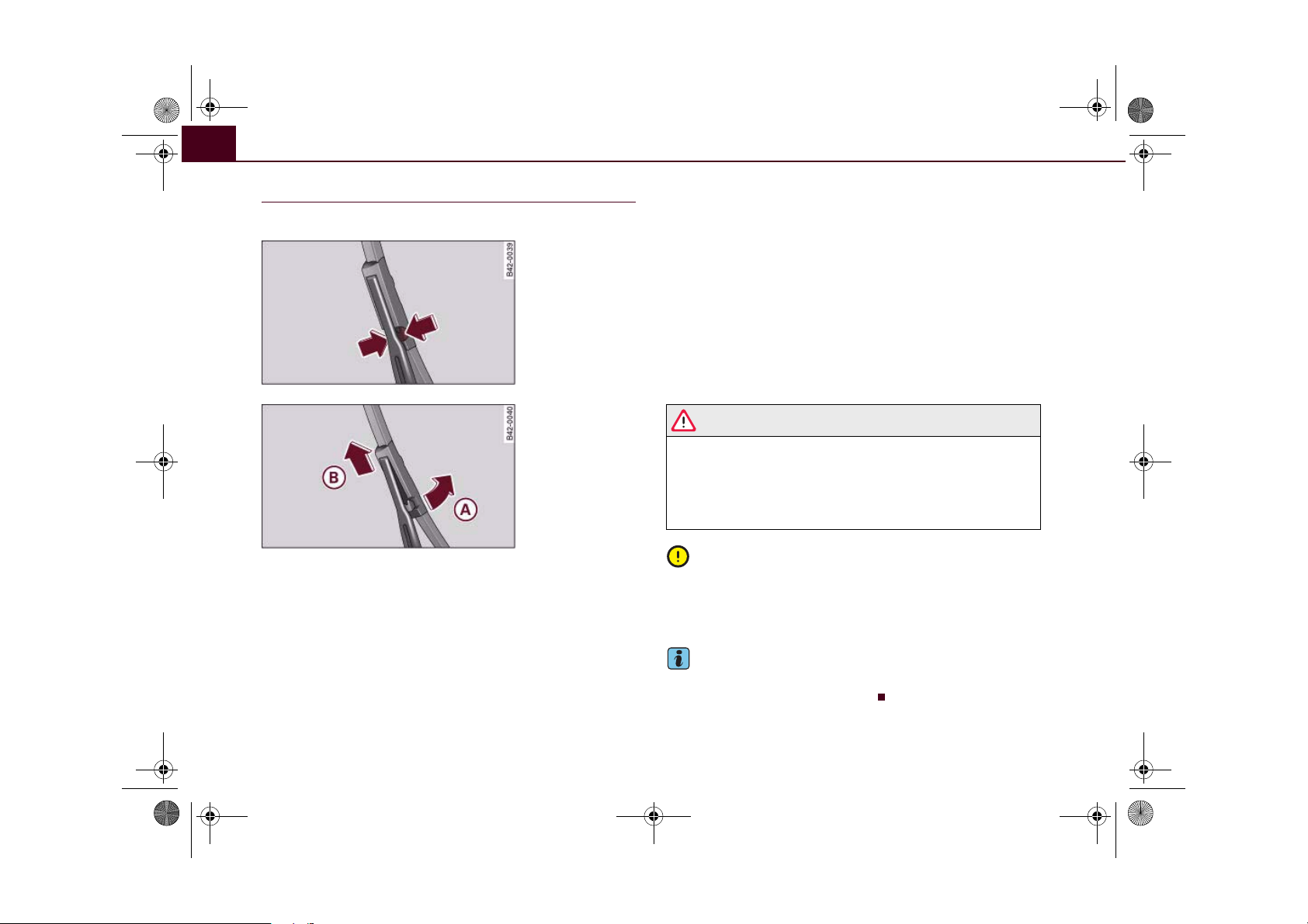
A
ABA
document_0900452a816e6cc9.book Seite 62 Mittwoch, 21. Februar 2007 1:32 13
Lights and vision62
Changing wiper blades
Good wiper blades are essential for clear vision.
Fig. 56 Releasing the
wiper blades
Fig. 57 Removing the
wiper blades
Taking off the wiper blade
– Place the wipers in the service position ⇒ page 61.
– Lift the wiper arm away from the glass.
– Press both sides of the plastic retainer at the top end of
the wiper arm together in the direction of the arrows
⇒ fig. 56.
– Now twist the wiper blade off the wiper arm in the direc-
tion of the arrow ⇒ fig. 57.
A
– Lift the wiper blade off in direction of the arrow .
Fitting the wiper blade
– Fit the plastic cap of the wiper blade onto the end of the
wiper arm (in opposite direction of arrow ⇒ fig. 57).
B
– Make sure you hear the retainer click into place on the
wiper arm.
– Fold the wiper arm back down onto the glass.
– Switch the ignition on and briefly press the windscreen
wiper lever downwards ⇒ page 61, fig. 55. The wipers
will return to their normal park position.
WARNING
• To prevent smearing on the glass, the wiper blades should be
cleaned regularly using a window cleaner solution. If the wiper
blades are very dirty (insects etc.), they should be cleaned using a
sponge or cloth – bad visibility can cause accidents.
• For safety, the wiper blades should be changed once or twice a
year.
Caution
The ignition must not be switched on while the front wiper arms are
in a raised position. The wipers would otherwise return to their park
position when you operate the windscreen wiper lever and damage
the paintwork on the luggage lid.
Note
The windscreen wiper blades differ in length, the wiper blade on the
driver's side is the shorter of the two.
Page 65

AAABAAA
document_0900452a816e6cc9.book Seite 63 Mittwoch, 21. Februar 2007 1:32 13
Lights and vision 63
Rear-view mirrors
Manual anti-dazzle adjustment
Normal setting
– Push the lever at the bottom of the mirror away from you.
Anti-dazzle setting
– Pull the lever at the bottom of the mirror towards you.
Applies to vehicles: with automatic anti-dazzle adjustment for interior mirror
Automatic anti-dazzle interior mirror
The automatic anti-dazzle function can be switched on
and off as desired.
Fig. 58 Anti-dazzle
interior mirror: Indicator lamp and on/off
switch
Switching off anti-dazzle function
– Press button ⇒ fig. 58 - the indicator lamp will go
out.
Switching on anti-dazzle function
– Press button ⇒ fig. 58 - the indicator lamp will light
up.
B
Anti-dazzle function
The anti-dazzle function is activated every time the ignition is
switched on. The green indicator lamp lights up in the mirror
housing.
When the anti-dazzle function is activated the interior mirror will
darken automatically according to the amount of light it receives
(for example from the headlights of a vehicle behind). The mirror
will not darken automatically:
• when the interior lighting is switched on
• when reverse gear is engaged
Sensors for automatic headlights
When the light switch is set to the AUTO position the dipped beam
headlights are switched on and off automatically according to the
ambient light level with the aid of the sensors located in the mirror
⇒ page 53.
WARNING
Electrolyte fluid can leak from a broken mirror. This fluid can cause
irritation to the skin, eyes, and respiratory organs. Wash thoroughly with clean water should you come into contact with this
fluid. Seek medical assistance if needed.
Caution
Electrolyte fluid leaking from a broken mirror can cause damage to
plastic surfaces. Use a sponge or similar to remove the fluid as soon
as possible.
Note
• If you switch off the anti-dazzle function for the interior mirror,
this will also deactivate the anti-dazzle function* for the exterior
mirrors.
Controls Safety Driving tips General maintenance Self-help Technical data
Page 66
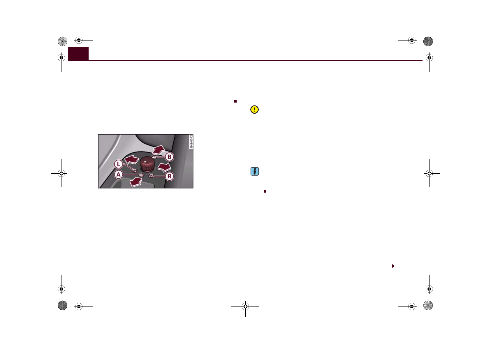
ALA
AAA
A
document_0900452a816e6cc9.book Seite 64 Mittwoch, 21. Februar 2007 1:32 13
Lights and vision64
• The automatic anti-dazzle function will only work properly if
there are no objects preventing light from reaching the interior
mirror.
• Do not attach any stickers to the windscreen in front of the
sensors, as this would interfere with the operation of the automatic
headlights and the automatic anti-dazzle function for the mirror.
Exterior mirrors
The exterior mirrors are adjusted electrically.
Fig. 59 Detail of the
armrest: Adjuster knob
Adjusting exterior mirrors
– Turn the adjuster knob to position (left exterior mirror)
or position (right exterior mirror) ⇒ fig. 59.
– Move the knob as required to adjust the exterior mirror
for a good rearward view.
Heated mirrors
– Turn the knob to position .
Retracting both exterior mirrors*
– Turn the knob to position .
R
B
The mirrors are heated depending on the outside temperature until
the ignition is switched off, even if the knob is no longer in position
A
.
It may be advisable to retract* the exterior mirrors to protect them
when parking or when driving through tight spaces.
Caution
• Convex or wide-angle exterior mirrors give a larger field of vision.
However, they also make objects appear further away than they
actually are. For this reason, you should not rely on these mirrors for
judging the distance of vehicles behind.
• If one of the mirror housings is knocked out of position (e.g.
when parking), the mirrors must first be fully retracted with the electric control. Do not readjust the mirror housing by hand, as this will
interfere with the mirror adjuster function.
Note
If the electrical adjustment should ever fail to operate, the mirrors
can be adjusted by hand by lightly pressing the edge of the mirror
glass.
Applies to vehicles: with automatic anti-dazzle adjustment for exterior mirrors
Automatic anti-dazzle adjustment for exterior
mirrors
The exterior mirrors darken together with the automatically
adjusting interior mirror. When the ignition is on, the mirrors will
darken automatically according to the amount of light received (for
example from the headlights of a vehicle behind).
When the interior lights are switched on, or when reverse gear is
engaged, the mirrors revert to their original (i.e. not darkened)
condition.
Page 67
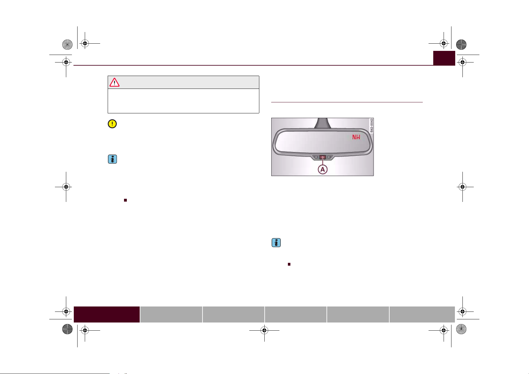
A
document_0900452a816e6cc9.book Seite 65 Mittwoch, 21. Februar 2007 1:32 13
Lights and vision 65
WARNING
Electrolyte fluid can leak from a broken mirror. This fluid can cause
irritation to the skin, eyes, and respiratory organs. Wash thoroughly with clean water should you come into contact with this
fluid. Seek medical assistance if needed.
Caution
Electrolyte fluid leaking from a broken mirror can cause damage to
the paintwork or plastic surfaces. Use a sponge or similar to remove
the fluid as soon as possible.
Note
• If you switch off the automatic anti-dazzle function for the inte-
rior mirror, this will also deactivate the automatic anti-dazzle function for the exterior mirrors.
• The automatic anti-dazzle function will only work properly if
there are no objects preventing light from reaching the interior
mirror.
Digital compass
Applies to vehicles: with digital compass
Activating and deactivating the compass
The compass direction will appear in the mirror.
Fig. 60 Interior mirror:
activated digital
compass
– To switch the compass on and off, press and hold
button until the compass display in the mirror
appears or disappears.
The digital compass only works when the ignition is on. The points
of the compass are displayed as follows: N (North), NE (North East),
E (East), SE (South East), S (South), SW (South West), W (West), NW
(North West).
To avoid inaccurate compass readings, do not hold any remote
controls or other electrical devices or metal objects near the interior
mirror.
A
Note
Controls Safety Driving tips General maintenance Self-help Technical data
Page 68
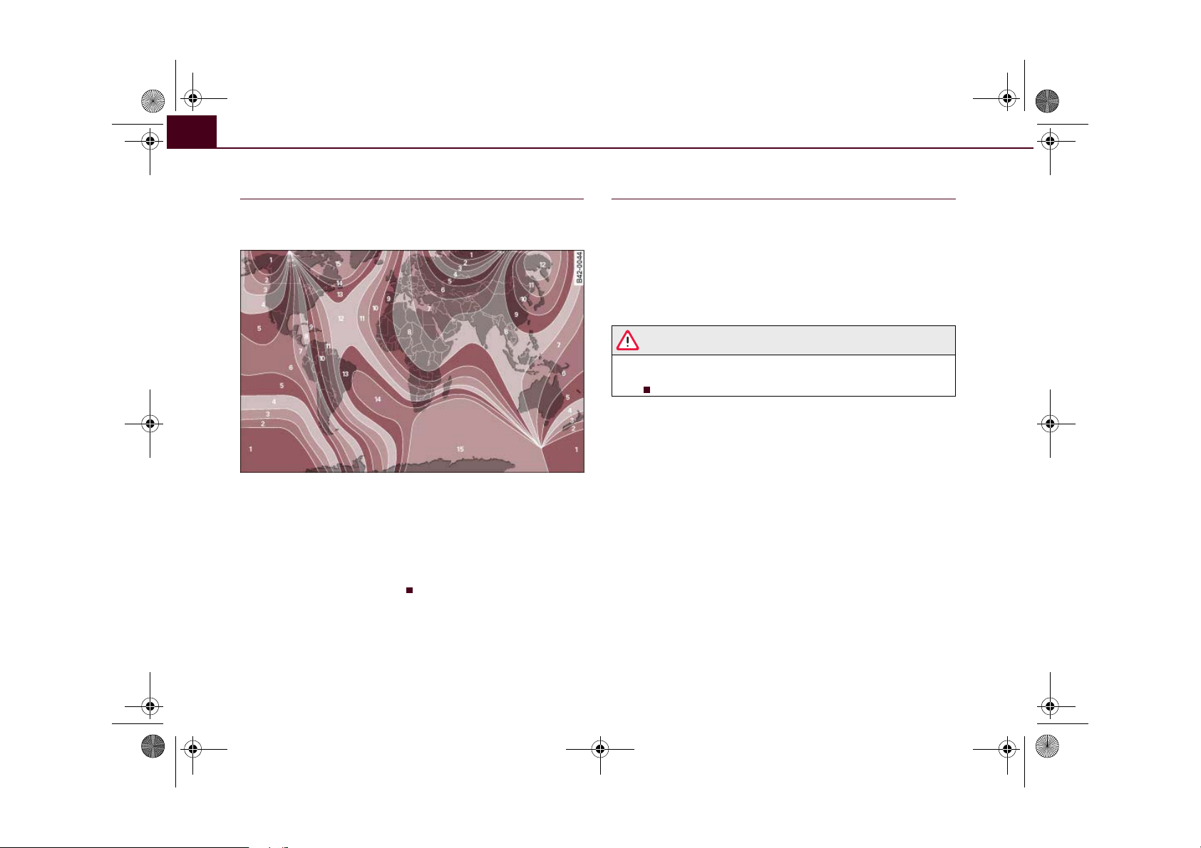
A
AAA
document_0900452a816e6cc9.book Seite 66 Mittwoch, 21. Februar 2007 1:32 13
Lights and vision66
Applies to vehicles: with digital compass
Setting the correct compass calibration zone
The correct compass calibration zone must first be set
before the compass can give an accurate reading.
Fig. 61 Map of compass calibration zones
– Press and hold button ⇒ page 65, fig. 60 until the
A
currently set zone number is displayed on the interior
mirror.
– Press button repeatedly until the correct zone number
appears. The adjustment mode will be ended automatically after a few seconds.
Applies to vehicles: with digital compass
Calibrating compass
The compass must be re-calibrated if the display is incorrect or inaccurate.
– Press and hold button until the letter C appears in the
A
interior mirror.
– Drive in a circle at a speed of about 10 km/h until a point
of the compass is displayed in the interior mirror.
WARNING
Calibrate your compass at a location where there is no traffic so
that you do not endanger yourself or other road users (accident
risk).
Page 69

A
A
A3A
A
A
A1A2A2A
document_0900452a816e6cc9.book Seite 67 Mittwoch, 21. Februar 2007 1:32 13
Seats and storage
Seats and storage 67
Manually adjustable front seats
Applies to vehicles: with manual seat adjustment
Seat adjuster controls
There are several seat adjustment functions for your
comfort and convenience
Fig. 62 Adjuster
controls on driver's
seat
Some of the controls shown are only fitted on certain models or are
optional extras.
Adjuster controls
1
Moves seat backwards or forwards
2
Adjusts lumbar support*
Adjusts seat height
4
Adjusts backrest angle
5
Unlocks backrest
Applies to vehicles: with manual seat adjustment
Seat adjustment
It is possible to adjust the position, angle and shape of the
seat so that you can travel in a safe and comfortable
sitting position.
Before adjusting your seat, please read and observe the
warnings ⇒ .
Moving seat backwards or forwards
– Lift the lever ⇒ fig. 62 and move the seat to the
1
desired position.
– Then release the lever and move the seat further until
the catch engages.
Adjusting contour of lumbar support*
– Press the front or rear part of the adjuster switch to
increase or decrease the curvature of the lumbar support
as required.
Adjusting height of lumbar support*
– Press the top or bottom part of the adjuster switch to
move the lumbar support upwards or downwards as
required.
Adjusting seat height
– Pull the lever up or down.
3
Adjusting the backrest angle
– Lean forwards to take your weight off the backrest.
Controls Safety Driving tips General maintenance Self-help Technical data
Page 70
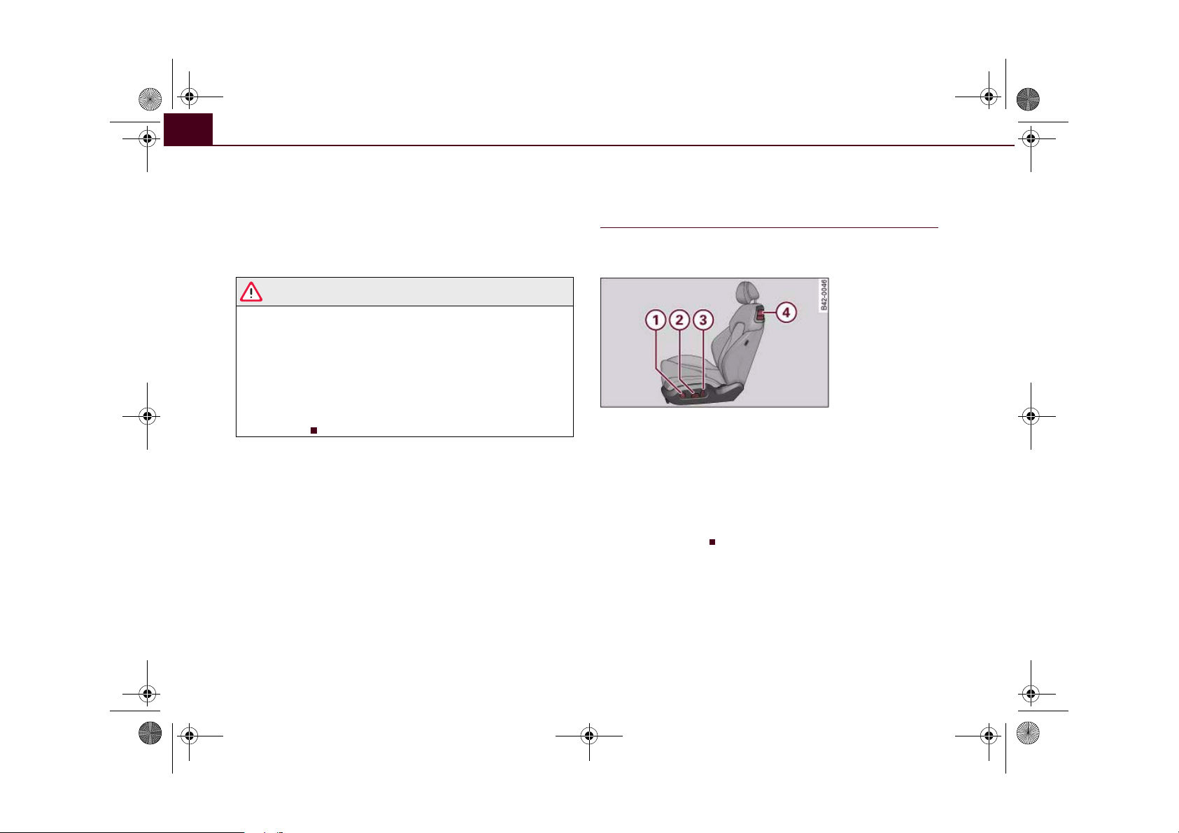
A4A
A1A
A
A
document_0900452a816e6cc9.book Seite 68 Mittwoch, 21. Februar 2007 1:32 13
Seats and storage68
– Turn the adjuster wheel to set the angle of the back-
rest as required.
Unlocking backrest
– Push the handle upwards.
5
– Fold the backrest forwards
WARNING
• Never adjust the driver's seat when the vehicle is moving - this
could lead to an accident.
• Be careful when adjusting the seat angle. Careless or uncon-
trolled use of the seat adjustment can cause injuries.
• Do not drive with the backrests of the front seats reclined too
far as otherwise the seat belt and airbag could fail to restrain the
wearer properly in an accident, possibly leading to injury.
• For safety reasons the front seat backrests must be locked
while driving.
Electrically adjustable front seats
Applies to vehicles: with electric seat adjustment
Seat adjuster controls
The arrangement of the switches corresponds with the
design of the seats.
Fig. 63 Front seat:
Adjuster controls
The adjustment switches for the seat and backrest correspond with
the design of the seat. The seats can be adjusted simply by pressing
the corresponding switch in the required direction.
Adjuster controls
Adjusts lumbar support
2
Adjusts seat height and moves seat backwards or forwards
3
Adjusts backrest angle
4
Unlocks backrest
Page 71

A1A1A2A2A2A2A
A
document_0900452a816e6cc9.book Seite 69 Mittwoch, 21. Februar 2007 1:32 13
Seats and storage 69
Applies to vehicles: with electric seat adjustment
Seat adjustment
You can use the electrical adjustment to set the position,
angle and shape of the seat so that you can travel in a
safe and comfortable sitting position.
Before adjusting your seat, please read and observe the
warnings ⇒ .
Adjusting contour of lumbar support*
– Press the front or rear part of the adjuster switch
⇒ page 68, fig. 63 to increase or decrease the curvature
of the lumbar support as required.
Adjusting height of lumbar support*
– Press the top or bottom part of the adjuster switch to
move the lumbar support upwards or downwards as
required.
Moving seat backwards or forwards
– Press the switch forwards or backwards.
Adjusting seat height
– Press the switch up or down.
Raising/lowering seat at front
– Press the front of switch up or down.
Unlocking backrest
– Push the handle upwards.
– Fold the backrest forwards
4
WARNING
• Never adjust the driver's seat when the vehicle is moving - this
could lead to an accident.
• The electrical seat adjustment also works when the ignition is
off and when the key is not in the ignition. To avoid accidental injuries, never leave children unattended in the vehicle.
• Be careful when adjusting the seat height. Careless or uncon-
trolled use of the height adjustment can cause injuries.
• Do not drive with the backrests of the front seats reclined too
far as otherwise the seat belt and airbag could fail to restrain the
wearer properly in an accident, possibly leading to injury.
• For safety reasons the front seat backrests must be locked
while driving.
Raising/lowering seat at rear
– Press the rear of switch up or down.
Adjusting the backrest angle
– Press the switch forwards or backwards.
Controls Safety Driving tips General maintenance Self-help Technical data
3
Page 72
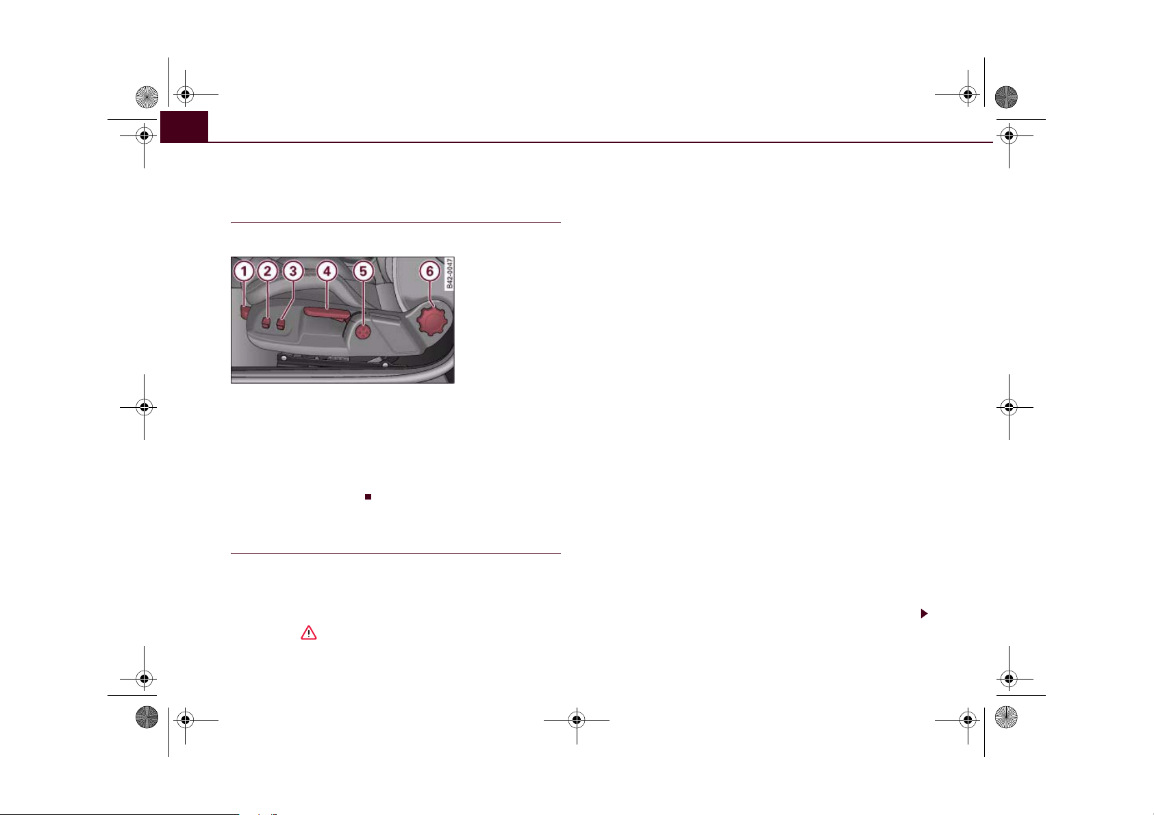
A
A
A
A4A
A
A
A1A2A3A4A5A5A5A
document_0900452a816e6cc9.book Seite 70 Mittwoch, 21. Februar 2007 1:32 13
Seats and storage70
Bucket seats
Applies to vehicles: with bucket seats
Seat adjuster controls
The bucket seat has several adjustment functions.
Fig. 64 Adjuster
controls on driver's
seat
Adjuster controls
1
Moves seat backwards or forwards
2
Inflates and deflates side padding
3
Inflates and deflates backrest side padding
Adjusts seat height
5
Adjusts lumbar support
6
Adjusts backrest angle
Applies to vehicles: with bucket seats
Seat adjustment
You can use the electrical adjustment to set the position,
angle and shape of the seat so that you can travel in a
safe and comfortable sitting position.
Before adjusting your seat, please read and observe the
warnings ⇒ .
Moving seat backwards or forwards
– Lift the lever ⇒ fig. 64 and move the seat to the
1
desired position.
– Then release the lever and move the seat further until
the catch engages.
Inflating and deflating side padding
– Press the button .
Inflating and deflating backrest side padding
– Press the button .
Adjusting seat height
– Pull the lever up or down.
Reinforcing top section of backrest
– Press the top of the adjuster control .
Reinforcing bottom section of backrest
– Press the bottom of the adjuster control .
Reinforcing both sections of backrest
– Press the front of the adjuster control .
Returning backrest sections to their "normal"
positions
– Press the rear of the adjuster control .
5
Adjusting the backrest angle
– Lean forwards to take your weight off the backrest.
Page 73

A6A
document_0900452a816e6cc9.book Seite 71 Mittwoch, 21. Februar 2007 1:32 13
Seats and storage 71
– Turn the adjuster wheel to set the angle of the back-
rest as required.
Unlocking backrest
– Press one of the two levers ⇒ page 68, fig. 63
upwards and fold down the backrest.
4
WARNING
• Never adjust the driver's seat when the vehicle is moving - this
could lead to an accident.
• The electrical seat adjustment also works when the ignition is
off and when the key is not in the ignition. To avoid accidental injuries, never leave children unattended in the vehicle.
• Be careful when adjusting the seat height. Careless or uncon-
trolled use of the seat adjustment can cause injuries.
• Do not drive with the backrests of the front seats reclined too
far as otherwise the seat belt and airbag could fail to restrain the
wearer properly in an accident, possibly leading to injury.
• For safety reasons the front seat backrests must be locked
while driving.
Head restraints
Front head restraints
In combination with properly worn seat belts, the head
restraints offer effective protection. However, they must
always be properly adjusted to suit the height of the occupant.
Fig. 65 Head restraint
– Take hold of the sides of the head restraint with both
hands.
– Adjust the head restraint so that the top of the head
restraint is level with the top of your head.
The height of the head restraints is adjustable. They should be set
to suit the height of the occupant. In combination with the seat
belts, the head restraints offer effective protection, provided they
are properly adjusted.
Controls Safety Driving tips General maintenance Self-help Technical data
Page 74

document_0900452a816e6cc9.book Seite 72 Mittwoch, 21. Februar 2007 1:32 13
Seats and storage72
Cup holders
Fig. 66 Cup holders
WARNING
• Do not put any hot drinks in the cup holders while the vehicle
is moving. You could be scalded if the hot liquid is spilt.
• Do not use hard china cups or glasses. These could cause injury
in the event of an accident.
Caution
You should avoid putting open drinks containers in the cup holders.
The drinks could otherwise spill over and cause damage to e.g. the
electrical equipment or the seat covers.
Ashtray
Fig. 67 Cen tre console:
Ashtray open
Opening ashtray
– Lift the cover.
Removing ashtray
– Open the cover all the way to the right.
– Take out the ashtray.
Inserting ashtray
– Insert the ashtray and press it into its mountings.
WARNING
Never put waste paper in the ashtray, as this could cause a fire.
Cigarette lighter and electrical socket
The 12 Volt socket for the cigarette lighter can also be
used as a power source for other electrical appliances.
The cigarette lighter and electrical socket only work when
the ignition is on.
Page 75
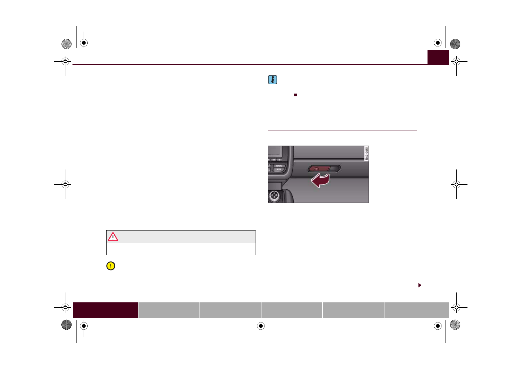
document_0900452a816e6cc9.book Seite 73 Mittwoch, 21. Februar 2007 1:32 13
Seats and storage 73
Using cigarette lighter
– Open the ashtray cover to access the cigarette lighter
⇒ page 72.
– Press in the cigarette lighter knob.
– Wait for the lighter to spring out.
– Pull out the cigarette lighter immediately.
– Use the glowing heater element of the cigarette lighter to
light your cigarette.
– Put the cigarette lighter back in its socket.
Operating electrical socket
– Open the cover to access the cigarette lighter.
– Take out the cigarette lighter.
– Insert the plug of the electrical appliance into the ciga-
rette lighter socket.
The cigarette lighter employs a standard 12 Volt socket which can
also be used as a power source for electrical appliances. The appliances connected to the socket must not exceed a power rating of
100 W.
WARNING
Take care when using the cigarette lighter. Carelessness or negligence when using the cigarette lighter can cause burns.
Caution
Always use the correct type of plugs to avoid damaging the sockets.
Note
Using electrical appliances with the engine switched off will drain
the battery.
Storage compartments
Glove box
The lockable glove box is equipped with a light.
Fig. 68 Glove box
Opening glove box
– Pull the catch on the lid in the direction indicated (arrow)
⇒ fig. 68 and open the lid.
Closing glove box
– Close the lid and push it in until it engages.
If the side lights or headlights are switched on, the light in the glove
box comes on when the glove box is opened. You will find a
compartment for (sun)glasses in the lid.
The glove box has a standard 12 Volt socket which can also be used
as a power source for electrical appliances. The appliances
Controls Safety Driving tips General maintenance Self-help Technical data
Page 76

document_0900452a816e6cc9.book Seite 74 Mittwoch, 21. Februar 2007 1:32 13
Seats and storage74
connected to the socket must not exceed a power rating of 100 W.
The socket will only work when the ignition is switched on.
WARNING
To avoid the risk of injuries, always keep the glove box lid closed
when driving.
Applies to vehicles: with storage compartments in the front seats
Storage compartments in the front seats
There is a fold-out drawer in the front part of each front
seat.
Opening
– Pull the handle to open the compartment.
Closing
– Close the lid and push it in until it engages.
Note
The storage compartment will hold a maximum weight of 1 kg.
Page 77

A
document_0900452a816e6cc9.book Seite 75 Mittwoch, 21. Februar 2007 1:32 13
Heating and cooling
Heating and cooling 75
Air conditioner
Controls
The air conditioner is designed to keep the passenger
compartment at the temperature you find most comfortable at all times of the year.
Fig. 69 Air conditioner controls
Recommended settings:
– Turn the control ⇒ fig. 69 to the right to switch the air
conditioner on.
– Set the temperature to 22 °C (72 °F).
– Press the button ⇒ fig. 69.
AUTO
2
This setting quickly provides a comfortable temperature inside the
vehicle. If necessary it can be changed to suit individual preferences
or particular circumstances.
The air conditioner provides heating and ventilation and also cools
and dehumidifies the air inside the vehicle.
The air conditioner is fully automatic, and will maintain the desired
temperature at a constant level. To achieve this, the temperature of
the air supplied to the interior, the blower speed (volume of air
delivery) and the air distribution are regulated automatically. The
system also allows for the effect of strong sunlight, so there is no
need for manual adjustment. For these reasons it is advisable to use
the automatic mode for the comfort of all the passengers in virtually
all conditions throughout the year ⇒ page 78.
Please note:
The humidity of the air is automatically reduced when the system
cools the interior of the vehicle. This helps to prevent condensation
on the windows. The air conditioner (compressor) will be switched
off automatically at low outside temperatures (below zero) and will
no longer dehumidify the air inside the vehicle.
If the humidity and temperature outside the vehicle are high,
condensation can drip off the evaporator in the air cooling system
and form a pool underneath the vehicle. This is normal and does not
indicate a leak.
If the outside temperature is low, the blower normally only switches
to a higher speed once the coolant has warmed up sufficiently (this
does not apply to the defrost setting).
In order to achieve maximum engine power, the air conditioner
compressor is temporarily switched off when pulling away from a
standstill with full throttle.
Controls Safety Driving tips General maintenance Self-help Technical data
Page 78

A
A
A
A
document_0900452a816e6cc9.book Seite 76 Mittwoch, 21. Februar 2007 1:32 13
Heating and cooling76
The compressor also switches off if the coolant temperature is
excessively high, to ensure adequate engine cooling under extreme
loads.
The functions can be set by turning the rotary control and are
switched on and off by briefly pressing the buttons. The LEDs in the
buttons light up when the function is switched on.
Buttons Function Page
Temperature selection ⇒ page 76
Rotary control
Rotary control
Rotary control
- +
AC
Pollution filter
The pollution filter (a particle filter) serves as a barrier against impurities in the outside air, including dust and pollen. The air is also
filtered when the air recirculation mode is activated.
For the air conditioner to work with maximum efficiency, the pollution filter element must be replaced at the intervals specified in the
Service Schedule.
If the vehicle is driven in areas with a high level of air pollution and
the filter is no longer fully effective, it may be necessary to change
the filter element more frequently.
1
Switches air conditioner
2
on/off
Blower
Air distribution ⇒ page 77
3
Defrosting windows ⇒ page 78
Heated rear window ⇒ page 79
Seat heating* (driver's
side/front passenger's
side)
Air recirculation mode ⇒ page 78
Switching the air condi-
tioner on
⇒ page 77
⇒ page 80
⇒ page 79
WARNING
For safety reasons it is important that all the windows are kept
free of ice, snow and condensation. These can cause poor visibility
and lead to an accident. Please familiarise yourself with the operating controls for the air conditioner, including the demist/defrost
functions for the windows.
Caution
• If you suspect that the air conditioner is damaged, switch it off
to prevent further damage and have the system checked by a qualified workshop.
• Repairs to the air conditioning system require specialist knowl-
edge and special tools. For this reason, please contact a qualified
workshop if the system is not working properly.
Note
• Keep the air intake slots in front of the windscreen clear of snow,
ice and leaves to ensure unimpaired heating and cooling, and to
prevent the windows misting over.
• The air conditioner operates most effectively with the windows
closed. However, if the vehicle has heated up after standing in the
sun for some time, the air inside can be cooled more quickly by
opening the windows for a short time.
Temp era ture s el ect io n
– Turn the rotary control ⇒ page 75, fig. 69 to the
required temperature setting.
Turn the rotary control to the left to reduce the temperature. Turn
the rotary control to the right to increase the temperature. There are
several intermediate positions, allowing you to adjust the temperature as required.
1
Page 79

A
A2A2A
A
A
A
document_0900452a816e6cc9.book Seite 77 Mittwoch, 21. Februar 2007 1:32 13
Heating and cooling 77
Switching air conditioner on or off
Switching air conditioner on or off
– Turn the control ⇒ page 75, fig. 69 clockwise to switch
2
the air conditioner on. The diode next to the word OFF
will go out.
– Turn the control ⇒ page 75, fig. 69 anti-clockwise to
switch the air conditioner off. The diode next to the word
OFF will light up.
Regulating the blower speed
– Turn the control ⇒ page 75, fig. 69 to the desired
setting for the blower speed (amount of air to be deliv-
ered).
In automatic mode, the air conditioning system automatically regulates the blower speed according to the interior temperature.
However, you can also adjust the blower speed manually.
Note
The blower speed will automatically be adjusted if the difference
between the selected temperature and the actual temperature in
the vehicle is too high. This ensures that the selected temperature
is reached as quickly as possible.
Air distribution
Fig. 70 Dashboard: Location of air outlets
– Turn the rotary control ⇒ page 75, fig. 69 to the
3
desired setting.
– The outlets can be opened and closed by turning the
adjustment ring.
– The direction of air delivery from these outlets can be
adjusted horizontally and vertically using the adjuster in
the centre of each outlet grille.
Air distribution:
• In position the air will flow only to the windows. Air outlets
2
and will be opened. For maximum defrosting effect on the side
windows in the driver's door and front passenger's door the
2
outlets should be directed at the side windows.
1
Controls Safety Driving tips General maintenance Self-help Technical data
Page 80
A2A3A
A1A2A4A2A
document_0900452a816e6cc9.book Seite 78 Mittwoch, 21. Februar 2007 1:32 13
Heating and cooling78
• In position the air will flow only to the driver/front passenger.
Air outlets and will be opened.
• In position the air will flow only to the footwells. Air outlets
will be opened.
• In position the air will flow only to the windows and the foot-
wells. Air outlets , and will be opened.
In addition to this there are several other possible combinations
(using intermediate positions), allowing you to adjust the air distribution to suit individual requirements.
Note
When the air conditioner is operating in the cooling mode, the air
should be directed mainly to outlets and . To ensure adequate
cooling effect, you should not close these outlets completely.
Defrosting
The windscreen and side windows are defrosted or
demisted as quickly as possible.
– To switch on, press the button ⇒ page 75, fig. 69.
– To switch off, press the button again, or press the
AUTO
button.
The temperature is regulated automatically. The air output is
increased to maximum and most of the air comes out of outlets 1
⇒ page 77.
A small, residual amount of air will emerge from outlets 2, if they are
open ⇒ page 77.
The air recirculation mode is switched off when the button is
pressed.
3
Automatic mode
Standard operating mode for all seasons.
4
AUTO
Switching on automatic mode
– Set the desired temperature.
– Press the button ⇒ page 75, fig. 69.
The automatic mode maintains a constant temperature inside the
vehicle and dehumidifies the air. Air temperature, air delivery and
air distribution are regulated automatically to reach the desired
interior temperature as quickly as possible, and then to maintain
this temperature. The system automatically compensates for any
variations in the outside temperature and for the effect of direct
sunlight.
Air recirculation mode
AUTO
The air recirculation setting prevents fumes etc. from
entering the interior.
Switching on the air recirculation mode
– Press the button ⇒ page 75, fig. 69, ⇒ .
Switching off the air recirculation mode
– Press the button again, or
– Press the button, or
– Press the button.
In this setting, the air is drawn from the interior of the vehicle,
filtered and continuously recirculated. We recommend using the air
recirculation mode for a brief period in the following circumstances
⇒ :
AUTO
Page 81
document_0900452a816e6cc9.book Seite 79 Mittwoch, 21. Februar 2007 1:32 13
Heating and cooling 79
When driving through a tunnel or in queues of traffic, to prevent
fumes entering the interior of the vehicle.
WARNING
For reasons of safety you should not leave the air recirculation
switched on for too long. This mode prevents fresh air from
entering the vehicle, so the windows can mist over if the air
cooling is switched off. Bad visibility can cause an accident.
AC mode
AC
Activating the AC mode
– Press the button ⇒ page 75, fig. 69.
AC
Deactivating the AC mode
– Press the button again.
In the AC mode, the air cooling system is switched on and the
heating and ventilation are regulated automatically.
AC
Note
If the LED in the AC button should continue to light up when the AC
mode has been switched off (i.e. the air conditioner has been
switched off) this is due to a defect in one of the air conditioner
components. If a malfunction should occur, please contact a qualified workshop.
Economical operation of the air conditioner
Economical operation of the air conditioner will help to
save fuel.
When the air conditioner is operating in the cooling mode it
reduces engine power and increases fuel consumption. To
ensure that the cooling mode is activated only when really
necessary, please note the following points:
– Switch the AC mode off if you wish to save fuel.
– Switch the AC mode off if you decide to open the
windows while driving.
– If the vehicle has heated up after standing in the sun,
open the windows and doors for a short time to cool the
vehicle.
For the sake of the environment
By saving fuel you also reduce the amount of pollutants emitted
from your vehicle.
Rear window heating
The rear window heating helps to demist the rear window.
– Press the button ⇒ page 75, fig. 69 to switch the rear
window heating on or off.
The rear window heating only works when the engine is running. An
indicator lamp in the button lights up when the rear window heater
is switched on.
The rear window heating switches off automatically after about
10 minutes.
Controls Safety Driving tips General maintenance Self-help Technical data
Page 82

document_0900452a816e6cc9.book Seite 80 Mittwoch, 21. Februar 2007 1:32 13
Heating and cooling80
For the sake of the environment
Switch off the heated rear window manually as soon as the rear
window is clear. By saving electrical power you can also save fuel.
Applies to vehicles: with seat heating
Seat heating
- +
The seat cushions and backrests of the front seats can be
heated electrically.
– Press the button for seat heating ⇒ page 75, fig. 69
- +
to set the desired seat temperature.
Possible settings range from 1 to 3. The selected seat heating
setting is indicated by LEDs above the button.
Caution
To avoid damaging the heating elements of the seat heating, please
do not kneel on the seat or apply sharp pressure at a single point.
Page 83

A
A
A
document_0900452a816e6cc9.book Seite 81 Mittwoch, 21. Februar 2007 1:32 13
Driving
Driving 81
Steering
Adjusting the steering wheel position
The height and reach of the steering wheel can be
adjusted as required to suit the driver.
Fig. 71 Lever beneath
steering column
–Push the lever ⇒ fig. 71 down ⇒ .
– Move the steering wheel to the desired position.
– Then push the lever towards the steering column until
the catch engages.
WARNING
• Never adjust the position of the steering wheel when the
vehicle is moving - this could cause an accident.
• For safety reasons, the lever must be securely engaged in its
top position to prevent the steering wheel from accidentally
changing position while driving, which could cause an accident.
Ignition lock
Ignition lock
The ignition key is used to start and switch off the engine.
Fig. 72 Ignition key
positions
Ignition off
In position ⇒ fig. 72 the ignition and the engine are switched off,
and the steering wheel lock can be engaged.
To engage the steering wheel lock, take out the key and turn the
wheel until you hear the pin engage. You should always engage the
steering lock when you leave the vehicle. This will help to deter theft
⇒ .
Ignition on (normal running position)
The needles in the instrument cluster will sweep across the dials
once after you switch on the ignition.
If the key is difficult to turn in the lock, move the steering wheel (to
take the load off the steering lock mechanism) until the key turns
freely.
1
1
2
Controls Safety Driving tips General maintenance Self-help Technical data
Page 84
A3A2A
A
A
document_0900452a816e6cc9.book Seite 82 Mittwoch, 21. Februar 2007 1:32 13
Driving82
Starting the engine
Turn the key to this position to start the engine. While the engine is
being started the headlights are switched back to side lights and
other major electrical equipment is switched off. After the engine
has started the ignition key returns to position by itself.
The ignition key has to be turned back to position before restarting the engine. The starter inhibitor in the ignition lock
prevents the starter motor from engaging when the engine is
running, as this could cause damage.
1
WARNING
• Wait for the vehicle to come to a standstill before removing the
ignition key from the lock. Otherwise the steering lock could
engage suddenly, which could cause an accident.
• Always take the key with you when leaving the vehicle – even
if you only intend to be gone for a short time. This is especially
important if children are left in the car. They might otherwise be
able to start the engine or use power-operated equipment such as
the electric windows - this could lead to injuries.
Note
If the battery has been disconnected and then reconnected it will be
necessary to leave the key in position for about 5 seconds before
starting the engine.
2
Starting the engine
The engine can only be started with an original Audi key.
On vehicles with R tronic, the engine can be started in
neutral (N) or in any gear (1 - 6 or R).
– Apply the handbrake firmly ⇒ .
– Push the clutch pedal all the way down (vehicles with
manual gearbox).
– Press and hold the brake pedal.
– Turn the ignition key to position ⇒ page 81, fig. 72
3
without pressing the accelerator.
– Release the ignition key as soon as the engine starts; the
starter motor must not be allowed to run on with the
engine. Neutral gear (N) will be engaged on vehicles with
Rtronic.
When starting from cold the engine may be a little noisy for the first
few seconds until oil pressure has built up in the hydraulic tappets.
This is quite normal, and no cause for concern.
If the engine fails to start straight-away, switch off the starter after
about 10 seconds and try again after about half a minute.
WARNING
• Never run the engine in confined spaces. The exhaust gases are
toxic.
• If the engine is running and a gear is engaged, you will need to
hold the car with the footbrake.
Caution
Avoid high engine speeds, full throttle and extreme load conditions
until the engine has reached its normal operating temperature,
otherwise this can damage the engine.
For the sake of the environment
Do not warm up the engine when the vehicle is stationary. You
should drive off immediately whenever possible. This will help avoid
unnecessary exhaust emissions.
Page 85

A
document_0900452a816e6cc9.book Seite 83 Mittwoch, 21. Februar 2007 1:32 13
Driving 83
Switching off the engine
On vehicles with R tronic, the engine can be switched off in
neutral (N) or in any gear (1 - 6 or R).
– Turn the ignition key to position ⇒ page 81, fig. 72.
1
WARNING
• Never switch off the engine until the vehicle is stationary.
• The brake servo and the power steering system work only
when the engine is running. You need more strength to steer and
brake the vehicle when the engine is switched off. This would
mean a greater risk of accidents and serious injury, because you
cannot steer and brake in the normal manner.
Caution
• If the engine has been working hard for a long time, there is a risk
of heat building up in the engine compartment after the engine has
been switched off; this could cause engine damage. For this reason,
you should leave the engine idling for a few minutes or drive at a
moderate speed to let the engine cool down before switching it off
⇒ page 139.
• Because the engine can get very hot after working hard, do not
park the vehicle on surfaces which could catch fire (e.g. on grass or
at the forest edge).
Note
After the engine is stopped the radiator fan may run on for up to
10 minutes, even if the ignition is switched off. The fan may also
start running again after some time if the coolant temperature rises
due to a build-up of heat, or if the engine is hot and the engine
compartment is heated up further by direct sunlight.
Handbrake
Handbrake
The handbrake should be applied firmly to prevent the
vehicle from accidentally rolling away.
Fig. 73 Detail of the
centre console: Handbrake applied
Applying the handbrake
– Pull the handbrake lever up all the way.
Releasing the handbrake
– Pull the lever up slightly and at the same time press in the
release button ⇒ fig. 73 -arrow-.
– Keep the release button pressed and push the lever all
the way down ⇒ .
The handbrake warning lamp lights up when the handbrake is
applied with the ignition on.
Controls Safety Driving tips General maintenance Self-help Technical data
Page 86
document_0900452a816e6cc9.book Seite 84 Mittwoch, 21. Februar 2007 1:32 13
Driving84
WARNING
Please note that the handbrake should be released all the way. If it
is only partially released this will cause overheating of the rear
brakes, which can impair the function of the brake system and
could lead to an accident.
Caution
Once the vehicle has come to a standstill, always apply the handbrake firmly and then engage a gear.
Parking the car
Please note the following points to ensure there is no risk
of the car rolling away accidentally after it is parked.
– Use the foot brake to stop the vehicle.
– Apply the handbrake firmly.
– Switch the engine off.
– Engage a gear ⇒ .
When parking on gradients
Turn the steering wheel so that the vehicle would roll into the kerb
if it did start to move accidentally.
WARNING
• Do not leave anyone (especially children) in the vehicle when it
is locked. Locked doors could delay assistance in an emergency,
potentially putting lives at risk.
• Never leave children unsupervised in the vehicle. They could,
for example, release the handbrake or put the gearbox in neutral.
The vehicle could then start moving and cause an accident.
Applies to vehicles: with hill hold assist
Driving away on a slope
The hill hold assist function makes it easier to drive away on a slope.
The system is activated when you press and hold the brake pedal for
a few seconds.
When you release the brake pedal the braking force will be main-
tained for a moment in order to hold the vehicle and make it easier
for you to drive away.
WARNING
• If you do not drive away immediately after releasing the brake
pedal the vehicle could start to roll back. You should therefore
immediately press the brake pedal or apply the handbrake.
• If the engine should stall you must immediately press the brake
pedal or apply the handbrake firmly.
• If you are driving away on a slope in stop-and-go traffic press
and hold the brake pedal for a few seconds before driving off. This
will prevent the vehicle from rolling back unintentionally.
Note
To find out whether your vehicle is equipped with the “hill hold
assist” function please contact an Audi R8 dealership or qualified
workshop.
Page 87

document_0900452a816e6cc9.book Seite 85 Mittwoch, 21. Februar 2007 1:32 13
Driving 85
Parking aid
Applies to vehicles: with 8-channel parking aid
Front and rear parking aid
The parking aid warns you if there are any obstacles
behind or in front of the car.
Fig. 74 Parking aid
switch in centre
console
Description
The front and rear acoustic parking aid (8-channel parking aid) uses
ultrasonic sensors to measure the distance between the vehicle and
an obstacle. The sensors are located in the front and rear bumpers.
The measuring range of the sensors starts at approximately:
Side sensors 0.60 m
Centre sensors at rear 1.50 m
Centre sensors at front 1.00 m
Activating
The parking aid is activated automatically when reverse gear is
engaged. This is confirmed by a short beep.
The parking aid can also be activated manually by pressing the
switch in the centre console ⇒ fig. 74. This is also confirmed by
a short beep. At the same time a diode in the switch will light up.
Activate the system manually if you are driving forwards and would
like the system to give warning as you approach potential obstacles,
for instance when parking.
Deactivating
The parking aid is switched off automatically when the vehicle
reaches a speed of about 15 km/h. It also switches itself off when
you stop the engine.
You can also deactivate the parking aid manually with the switch
⇒ fig. 74.
Warning beeps
The warning beeps are produced by sound boxes located at the
front and rear of the vehicle. You can adjust the volume and pitch of
the beeps ⇒ page 24.
Reversing
When the vehicle is reversing, the system starts to beep when it
registers an obstacle within its detection range (see above). The
warnings will beep increasingly rapidly as the vehicle approaches
the obstacle.
When the vehicle is less than 0.35 m away from the obstacle the
warning tone will sound continuously. The driver should then not
reverse any further.
Please note that low obstacles detected by the system may no
longer be registered by the sensors as the car moves closer, so the
system will not give any further warning.
Driving forwards
The same proximity warnings are given when driving forwards, but
obstacles have to be within a slightly closer range before they are
detected (the front measuring range is shorter). The warning tone
will sound continuously when the vehicle is less than 0.30 m away
from the obstacle.
Controls Safety Driving tips General maintenance Self-help Technical data
Page 88

document_0900452a816e6cc9.book Seite 86 Mittwoch, 21. Februar 2007 1:32 13
Driving86
Parking
If the parking manoeuvre involves shunting backwards and
forwards, the warning sound will be switched off temporarily while
you change gear. The warning beeps will start again as soon as the
vehicle comes closer to an obstacle.
Possible faults
If you hear a long beep when you engage reverse gear (or when you
activate the system using the switch) and the diode in the switch
starts flashing, there is a fault in the system. The long warning beep
is given just once to indicate the fault. If you try activating the
parking aid again, the warning beep will not sound and fault is only
indicated by the flashing diode. This also applies if you switch the
ignition off and then on again: the long warning beep will only
sound the first time you try activating the parking aid. Have the fault
rectified.
If there is a fault in the system there will be no confirming beep
when you activate the parking aid.
To ensure that the acoustic parking aid works properly, the sensors
must be kept clean and free of ice.
WARNING
• The sensors have blind spots in which obstacles are not regis-
tered. It is particularly important to ensure that there are no small
children or animals near the vehicle when reversing, as the
sensors may not always be able to detect them.
• The parking aid cannot replace the full concentration of the
driver. The driver is always responsible for safety during parking
and other manoeuvres.
Caution
Please note that low obstacles detected by the system may no
longer be registered by the sensors as the car moves closer, so the
system will not give any further warning. Certain kinds of obstacles
(such as wire fences, chains, thin painted posts or trailer draw bars,
etc) may not always be detected by the system, so take care not to
damage the vehicle in such cases.
Note
Your vehicle has low ground clearance. To help you prevent damage
to the vehicle, warning beeps will sound when you approach a steep
slope (e.g. in a car park or garage).
Cruise control system
Applies to vehicles: with cruise control system
Introduction
The cruise control system allows you to maintain a
constant speed.
The cruise control system allows you to maintain any desired
constant cruising speed at speeds above about 30 km/h. Of course,
this is subject to power output and braking ability of the engine.
This helps to reduce fatigue, especially on long journeys.
The indicator lamp in the instrument cluster lights up when the
cruise control system is operating.
The cruise control system is automatically deactivated immediately
by
• pressing the brake pedal.
• pressing the clutch pedal.
WARNING
For safety reasons the cruise control system should not be used in
dense traffic or poor road conditions (such as slippery surfaces,
heavy rain, loose grit or gravel) – this could cause an accident.
Page 89
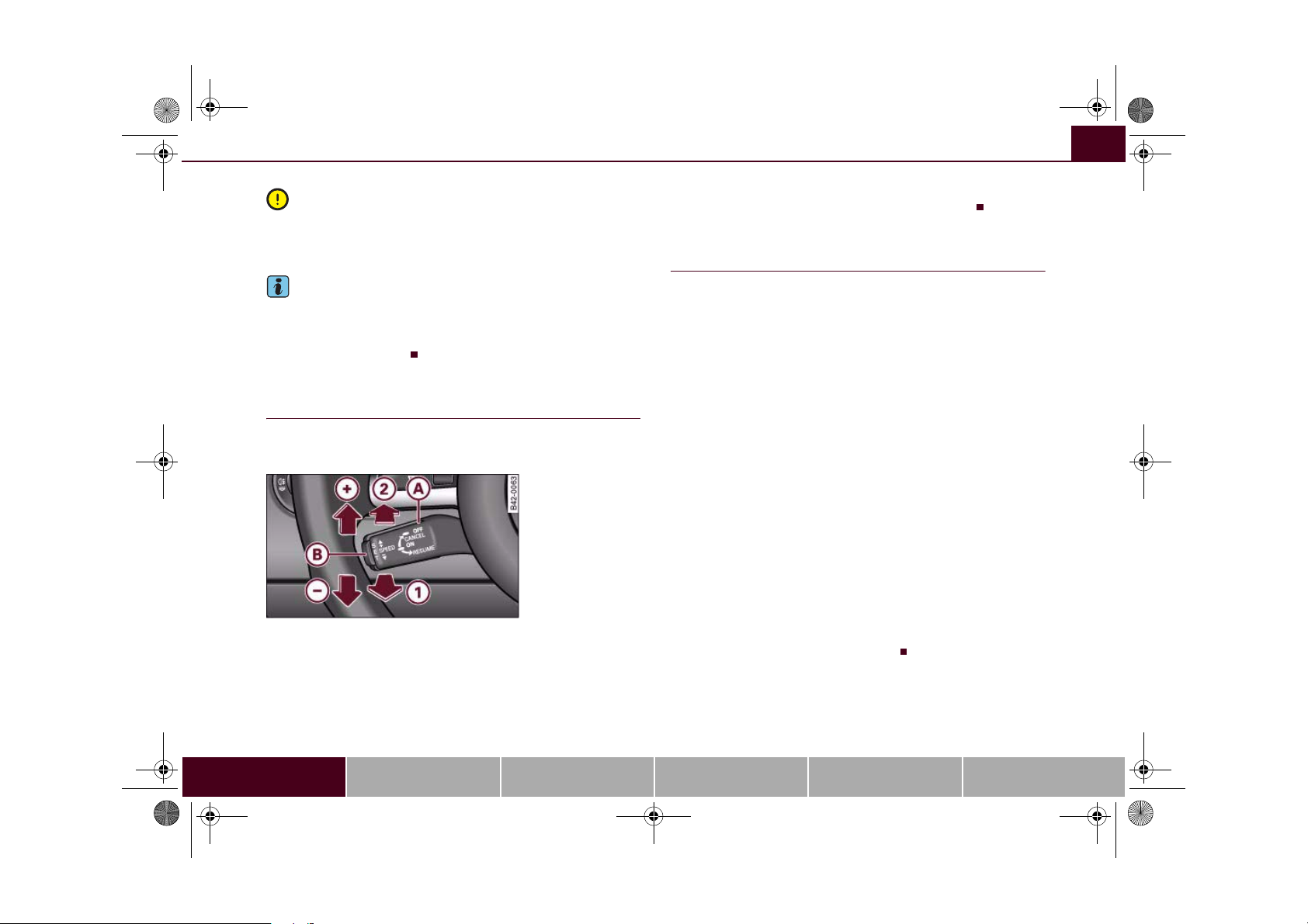
AAA
A
A
AAA+AAA
AAAAA
AAA
document_0900452a816e6cc9.book Seite 87 Mittwoch, 21. Februar 2007 1:32 13
Driving 87
Caution
do not move the gear lever into neutral without depressing the
clutch when the cruise control system is active. Otherwise the
engine could rev up and be damaged.
Note
The cruise control cannot maintain a constant speed when travelling down steep hills. The vehicle tends to accelerate under its own
weight. Change down to a lower gear in good time or use the foot
brake to slow the vehicle.
Applies to vehicles: with cruise control system
Setting speed
The desired cruising speed needs to be stored in the
memory.
Fig. 75 Controls for
the cruise control
system
– Drive at the desired speed.
– Pull the lever to position ⇒ fig. 75 to switch on the
1
system.
– Briefly press button .
B
When button is released, the current speed is stored in the
memory and the vehicle will then maintain this speed.
Applies to vehicles: with cruise control system
B
Adjusting stored speed
The desired cruising speed can be adjusted up or down as
required.
To set a higher speed
– Move the lever up towards ⇒ fig. 75 .
– Release the lever to store the current cruising speed.
To set a lower speed
– Move the lever down towards ⇒ fig. 75 .
-
– Release the lever to store the current cruising speed.
You can still use the accelerator pedal to increase speed in the
normal way. The previously programmed speed will be resumed
when the accelerator pedal is released.
However, if the vehicle exceeds the programmed speed by more
than 10 km/h for more than 5 minutes, the cruise control system will
be deactivated. The speed setting will remain stored.
Pressing lever briefly
You can increase the set speed in steps of 2 km/h by briefly pressing
the lever up towards ⇒ fig. 75 .
You can decrease the set speed in steps of 2 km/h by briefly pressing
the lever down towards ⇒ fig. 75 .
+
-
Controls Safety Driving tips General maintenance Self-help Technical data
Page 90

AAA
AAA1A
A
document_0900452a816e6cc9.book Seite 88 Mittwoch, 21. Februar 2007 1:32 13
Driving88
Applies to vehicles: with cruise control system
Switching off cruise control temporarily
– Press the brake pedal, or
– Press the clutch pedal, or
– Press the lever ⇒ page 87, fig. 75 to position (click
2
stop not engaged).
The speed stored at this point remains in the memory if the system
is only temporarily deactivated.
To resume the programmed cruising speed, release the clutch or
brake pedal and pull the lever to position .
If no speed was stored when the system was temporarily deactivated, a new speed can be set as follows: drive at the desired
cruising speed and briefly press button ⇒ page 87, fig. 75 (SET).
B
WARNING
Do not resume the programmed cruising speed if this is too high
for the traffic conditions - this can cause accidents.
Applies to vehicles: with cruise control system
Switching off cruise control
– Press the lever A ⇒ page 87, fig. 75 to position (click
2
stop engaged).
The stored speed will be deleted once the ignition is switched off.
Note
Always switch off the cruise control system completely after each
journey. When beginning a new journey, the speed must be reset
⇒ page 87.
Applies to vehicles: with Audi magnetic ride
Audi magnetic ride
The damping effect of the shock absorbers can be
adjusted according to the driver's requirements, and will
adapt automatically to suit the driving conditions.
Fig. 76 Cen tre console:
Switch for Audi
magnetic ride
– Press the switch ⇒ fig. 76 to activate or deactivate the
sport driving mode.
Audi magnetic ride is an electronically controlled damping system.
By means of control processes going on in the background it assists
the driver and adapts automatically to particular situations when
driving. The adaptive damping varies the stiffness of the shock
absorbers to suit individual requirements. For example, if the driver
selects the comfort setting, the suspension damping is relatively
soft and only becomes firmer when required, such as in a corner or
under braking.
Normal driving mode
Select the normal setting for comfort-oriented suspension characteristics.
Page 91
document_0900452a816e6cc9.book Seite 89 Mittwoch, 21. Februar 2007 1:32 13
Sport driving mode
Select the sport setting for performance-oriented suspension characteristics. The diode in the switch will light up to indicate that the
sport mode is on.
Note
The warning lamp lights up in the instrument cluster if a malfunction occurs. Drive to the nearest qualified workshop as soon as
possible and have the fault corrected.
Driving 89
Controls Safety Driving tips General maintenance Self-help Technical data
Page 92

document_0900452a816e6cc9.book Seite 90 Mittwoch, 21. Februar 2007 1:32 13
Automatic gearbox90
Automatic gearbox
Applies to vehicles: with R tronic
Description
Fig. 77 Gear shift
pattern
Fig. 78 Display:
Engaged gears
R tronic is an automatic sequential-shift gearbox using shift-by-wire
technology to operate the clutch and change the gears.
The gears are engaged manually (the principle is similar to a manual
gearbox) but they can also be shifted automatically. The engine can
be started and stopped in any gear ⇒ page 82.
The driver information system displays the selected mode, the
engaged gear and the sport function ⇒ fig. 78.
M - Manual mode
In this mode, you use the selector lever ⇒ page 91 or the paddle
levers on the multi-function steering wheel ⇒ page 93 to change
the forward gears up and down.
A - Automatic mode
In this mode the forward gears are shifted up and down automatically according to the engine load and road speed ⇒ page 92.
R - Reverse gear
Reverse gear must only be engaged when the vehicle is stationary
and the engine is idling ⇒ .
To engage reverse gear press the brake pedal then move the
selector lever to the right before pulling it briefly towards the R
symbol. The reversing lights come on when reverse gear is engaged
with the ignition on.
N - Neutral
To engage neutral gear, the selector lever has to be moved to the
right or left. If reverse gear is engaged, move the selector lever to
the left. If a forward gear is engaged, move the selector lever to the
right.
Sport function
Press the button to activate the sport function. Upshifts are
then delayed to make use of the maximum engine power. The shift
time is reduced and the accelerator pedal has a lighter response. In
addition, the car does not automatically shift up a gear before the
maximum engine speed is reached when you are in manual mode.
The car will automatically shift up a gear in the normal way when
you are in automatic mode.
SPORT
Page 93

A
A+A
document_0900452a816e6cc9.book Seite 91 Mittwoch, 21. Februar 2007 1:32 13
Automatic gearbox 91
WARNING
• The accelerator pedal must on no account be pressed inadvert-
ently when a gear is engaged with the vehicle stationary. If this
were to happen, the vehicle would start to move immediately, and
even a firmly applied handbrake might not restrain it (accident
risk).
• To avoid accidents, apply the handbrake firmly and select
neutral gear (N) before opening the engine lid and working on the
vehicle with the engine running. Please observe the important
safety warnings ⇒ page 155, “Working on components in the
engine compartment”.
Note
If you accidentally shift to N when driving, you can engage a gear in
the normal way using the selector lever or paddle levers.
Applies to vehicles: with R tronic
Manual mode
R tronic allows the driver to change gears manually.
Driving away from a standstill
– Press and hold the brake pedal.
– Move the selector lever to the left.
– Briefly push the selector lever forwards .
– Release the brake and press the accelerator ⇒ .
Changing gear
– Briefly push the selector lever forwards to change up
a gear.
+
– Briefly pull the selector lever back to change down a
-
gear.
Stopping briefly
– Apply the foot brake to hold the vehicle when stationary
(for instance at traffic lights).
– Do not press the accelerator while waiting. Neutral gear
(N) will be engaged automatically and a warning tone will
sound after a certain period if the vehicle is at a standstill
and you do not press the brake pedal or accelerator.
Parking
– Press and hold the brake pedal ⇒ .
– Apply the handbrake firmly.
– Engage a gear.
– Switch off the ignition.
Stopping on a slope
– Always apply the footbrake to hold the vehicle and
prevent it “rolling back” down the slope ⇒ . Do not try
to stop the vehicle “rolling back” by increasing the
engine speed when a gear is engaged.
– Apply the handbrake firmly.
Driving away on a slope
– Once you have engaged a gear, release the footbrake,
press the accelerator and gradually release the handbrake.
When accelerating in 1st, 2nd, 3rd, 4th or 5th gear, the R tronic
gearbox automatically shifts up into the next gear shortly before the
Controls Safety Driving tips General maintenance Self-help Technical data
Page 94
document_0900452a816e6cc9.book Seite 92 Mittwoch, 21. Februar 2007 1:32 13
Automatic gearbox92
maximum engine speed is reached, unless you have activated the
sport function ⇒ page 90.
If you select a lower gear, the R tronic gearbox will not shift down
until there is no risk of overrevving the engine.
You can change over to automatic mode at any time ⇒ page 92.
WARNING
• The driver should never get out of the vehicle when the engine
is running and a gear is engaged. If you have to leave your vehicle
while the engine is running, you must apply the parking brake and
engage neutral gear (N).
• If the engine is running and a gear is engaged, you will need to
hold the car with the footbrake.
• Do not press the accelerator while selecting a gear with the
vehicle stationary and the engine running, as this could cause an
accident.
• To avoid rolling back on gradients always hold the vehicle with
the footbrake if you have to stop. Never attempt to hold the vehicle
with the clutch when stopping on a gradient. The clutch is disengaged automatically if it is overloaded and becomes too hot - accident risk! Before the clutch is disengaged, the vehicle will jolt and
the driver information system will display a warning that the
clutch is overloaded.
• Before you drive down a steep gradient, reduce the speed and
use the R tronic to select a lower gear.
• Never allow the brake to drag and do not use the brake pedal
too often or for long periods. Constant braking will cause the
brakes to overheat and will considerably reduce the effectiveness
of the brakes. It will increase the braking distance and could cause
the brake system to fail.
Applies to vehicles: with R tronic
Automatic mode
The gearbox changes the forward gears up and down
automatically.
Driving away from a standstill
– Press and hold the brake pedal.
– Briefly push the selector lever towards position A.
– Release the brake and press the accelerator ⇒ in
“Manual mode” on page 91.
In some situations (such as when driving on mountain roads) it can
be advantageous to switch temporarily to the manual shift
programme ⇒ page 91, so that the gear ratios can be selected
manually to suit the driving conditions.
Applies to vehicles: with R tronic
Kick-down feature
When the accelerator pedal is pressed right down past the point of
resistance at full throttle, the R tronic gearbox will shift down to a
lower gear, depending on road speed and engine speed. The upshift
to the next higher gear is delayed until the engine reaches
maximum rpm. This does not apply if you have activated the sport
function.
WARNING
Please note that if the road surface is slippery or wet, the kickdown feature could cause the driving wheels to spin, which could
result in skidding.
Page 95

A
A
document_0900452a816e6cc9.book Seite 93 Mittwoch, 21. Februar 2007 1:32 13
Automatic gearbox 93
Applies to vehicles: with R tronic
Launch control programme
The launch control programme enables maximum acceleration.
– Press the ESP switch once while the engine is running.
The ESP warning lamp
will light up in the driver infor-
mation system display.
– Press and hold the brake pedal with your left foot.
– Engage a gear.
– Press the button.
SPORT
– Press the accelerator all the way down with your right
foot until the engine reaches a constant rpm speed.
– Take your left foot off the brake ⇒ .
WARNING
• Always adapt your driving style to the traffic conditions.
• Only use the launch control programme when road and traffic
conditions permit, and make sure your manner of driving and
accelerating the vehicle does not inconvenience or endanger other
road users.
• Please note that, when the ESP is switched off, the driven
wheels may start to spin, causing the vehicle to lose grip, in particular on slippery or wet roads - danger of skidding!
• When acceleration has been completed, the ESP should be
reactivated by pressing the ESP switch.
Note
Accelerating with the launch control programme places a heavy
load on all parts of the vehicle. This can result in increased wear and
tear.
Applies to vehicles: with R tronic
Steering wheel with paddle levers
The paddle levers behind the steering wheel allow you to
change gear manually without taking your hands off the
steering wheel.
Fig. 79 Sp orts stee ring
wheel with Paddle
levers
– Briefly pull the left-hand paddle lever to change down
to a lower gear.
– Briefly pull the right-hand paddle lever to change up
to a higher gear.
The manual shift programme can, of course, still be operated using
the selector lever in the centre console.
-
+
Controls Safety Driving tips General maintenance Self-help Technical data
Page 96
document_0900452a816e6cc9.book Seite 94 Mittwoch, 21. Februar 2007 1:32 13
Automatic gearbox94
Applies to vehicles: with R tronic
Backup programme
A back-up system is in place if a fault should occur in the
control system.
The R tronic gearbox switches to the back-up programme if a fault
should occur in the control system. If this happens, a red bar will
light up or flash in the driver information system display.
A permanently lit bar indicates that you can continue driving the
vehicle.
A flashing bar indicates a serious system fault:
• The programme will only move into certain gears.
• The engine may stall.
• The engine cannot be started again after it is switched off.
• The vehicle may be damaged if you continue driving.
Caution
If the R tronic gearbox should ever switch to the back-up
programme you should take the vehicle to a workshop as soon as
possible.
Page 97
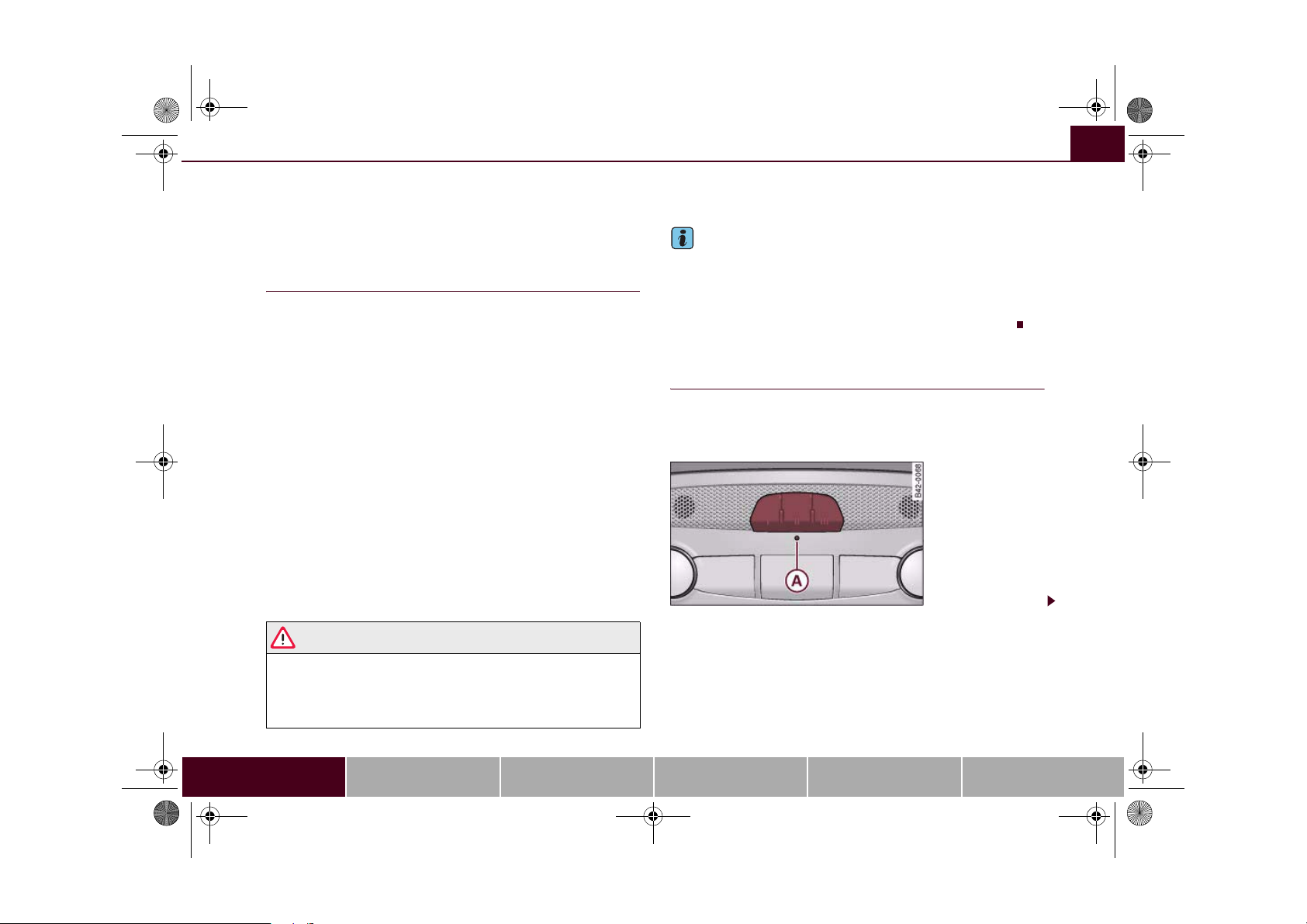
document_0900452a816e6cc9.book Seite 95 Mittwoch, 21. Februar 2007 1:32 13
HomeLink
HomeLink 95
Universal transmitter
Applies to vehicles: with HomeLink
Description
The HomeLink universal transmitter can be programmed
to replace the hand-held controls of devices already in
use.
The HomeLink universal transmitter allows you to conveniently activate garage doors, estate gates, security systems, home or office
lighting and other electric devices by means of control buttons
inside your car.
The single remote control unit that HomeLink provides will replace
up to three hand-held transmitters operating existing devices on
your property. This will be possible for most transmitters which
control the drive units for a garage door or external gates, etc.
Programming of the individual hand-held transmitters for your
remote control is done at the centre of the front bumper. This is
where the control unit is located.
To be able to control systems with HomeLink, you need to perform
initial programming on the HomeLink transmitter first. If systems
fail to respond after the initial programming, check whether these
systems work with a "rolling code" (variable security code)
⇒ page 97.
WARNING
When you are programming the HomeLink universal transmitter,
make sure that no persons or objects are close to the devices
receiving the transmitter signals. If a gate or door is inadvertently
set into motion during programming, persons might be injured or
other damage caused by moving parts.
Note
• For additional information on HomeLink® and/or products
compatible with HomeLink®, please call the toll-free HomeLink®
hotline (0) 08000466 35465 (in Germany) or alternatively +49 (0) 6838
907 277, or visit the HomeLink® website at: www.homelink.com
• HomeLink
Applies to vehicles: with HomeLink
Programming the universal transmitter
Programming of the HomeLink universal transmitter is
done on the operating unit located above the interior
mirror and at the front bumper.
®
is a registered trademark of Johnson Controls.
Fig. 80 Operating unit
above the interior
mirror
Controls Safety Driving tips General maintenance Self-help Technical data
Page 98
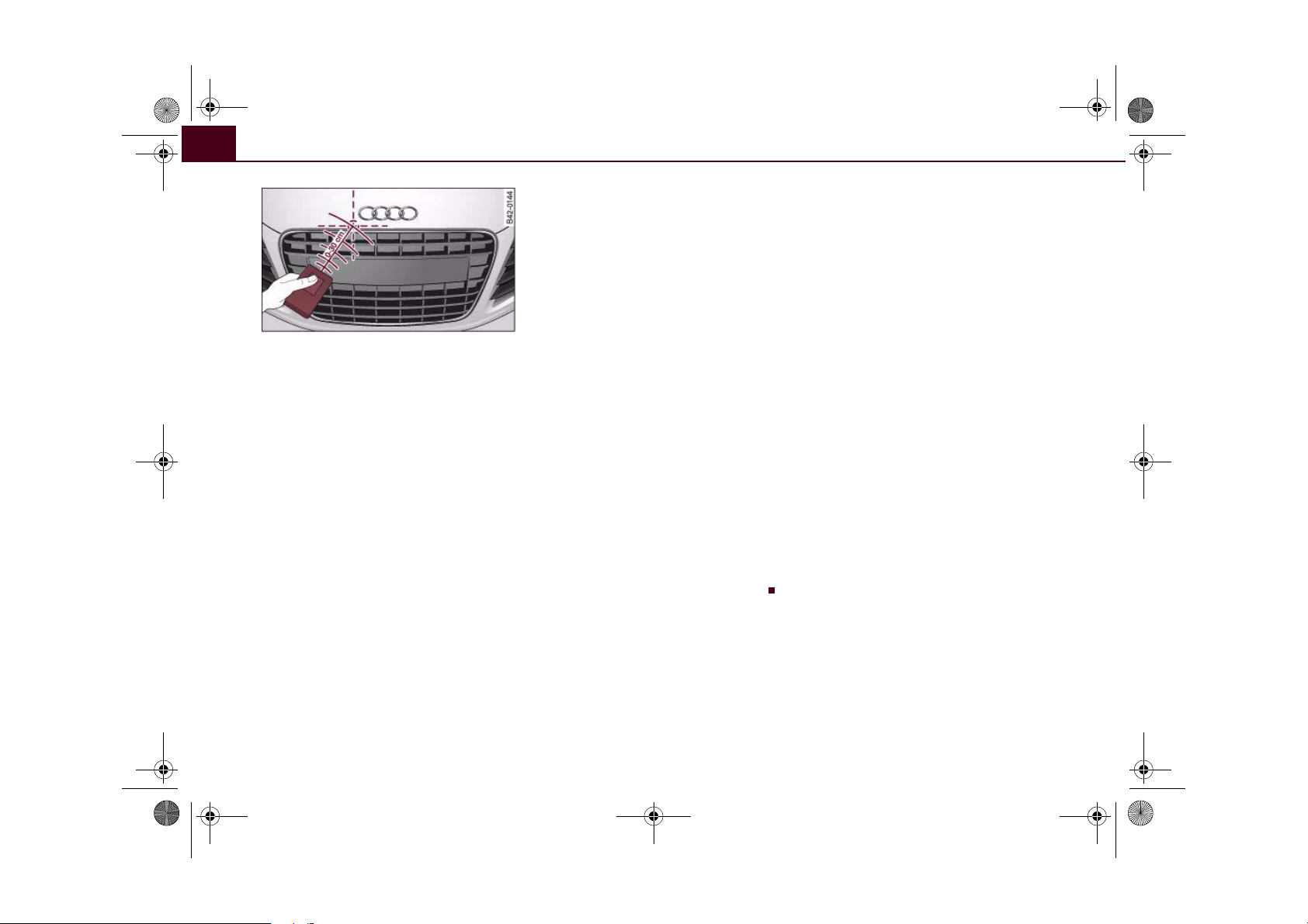
A
A
document_0900452a816e6cc9.book Seite 96 Mittwoch, 21. Februar 2007 1:32 13
HomeLink96
Fig. 81 Front bumper
At the operating unit
1. Switch on the ignition (do not start the engine).
2. Press and hold down the two outer buttons of the
HomeLink® operating unit ⇒ page 95, fig. 80 until the
indicator diode ⇒ page 95, fig. 80 begins to flash after
A
about 20 seconds. This means that all previously stored
data has been deleted.
3. Press the particular HomeLink button which you would
like to program.
4. Wait until the diode ⇒ page 95, fig. 80 begins to flash.
A
The HomeLink module now remains in training mode for
5 minutes.
5. Now step in front of your vehicle with the original hand-
held transmitter for the garage door opener or any other
device you wish to assign to the HomeLink control button
⇒ fig. 81.
7. Press the activator button on the original hand-held
transmitter.
8. As you do so, watch the turn signals on your vehicle.
HomeLink confirms successful programming by flashing
all four turn signals three times.
9. If the turn signals fail to flash three times, repeat the
procedure with the transmitter held at a different
distance from the bumper.
The proper distance between the hand-held transmitter and the
HomeLink module inside the front bumper depends on the system
you want to train. It may require several attempts.
The turn signals will flash once if the time limit for the programming
mode has been exceeded. In this case the programming procedure
needs to be performed again. Repeat the sequence on the operating
unit starting with step 3.
The programming instructions above also apply to the other control
buttons. Start with step 3 on the operating unit if you wish to
proceed and program the other two buttons.
If the garage door or other devices still fail to be activated with the
HomeLink control buttons after programming is completed, it is
possible that these systems might be working with a rolling code
instead of the normal fixed security code. If this is the case, a rolling
code programming is required in addition to the steps described
above ⇒ page 97.
At the front bumper
6. Hold the original hand-held transmitter for the device
you wish to program close to the front bumper, directly
above the radiator grille ⇒ fig. 81.
Page 99
A
document_0900452a816e6cc9.book Seite 97 Mittwoch, 21. Februar 2007 1:32 13
HomeLink 97
Applies to vehicles: with HomeLink
Rolling code programming
Some devices require rolling code programming of the
HomeLink universal transmitter.
Identifying a rolling code
– Press the already programmed HomeLink button again
and hold it down.
–Watch HomeLink diode ⇒ page 95, fig. 80. If the diode
A
starts flashing rapidly and turns into a constant light
after about 2 seconds, this indicates that the device you
wish to operate (e.g. a garage door opener) is equipped
with a rolling code.
– Program the rolling code as follows:
Activating the garage door opener drive unit
– Locate the programming button on the garage door
drive. The exact location and colour of the button may
vary depending on the type of garage door opener.
– Press the programming button on the door drive unit
(this will normally cause a “programming mode indicator
lamp” on the unit to light up). You now have about 30
seconds to start and complete programming of the
HomeLink control button on the operating unit.
Programming of the operating unit above the
interior mirror
– Press and release the already programmed HomeLink
button.
– Press the HomeLink button again to complete rolling
code programming.
After programming at the operating unit, the garage door opener
should recognise the HomeLink signal and respond when the
HomeLink button is pressed. Now the other control buttons can be
programmed as required.
Note
• Having a second person assist you makes programming of the
rolling code easier and faster. For some makes of garage door
openers the HomeLink button may have to be pressed a third time
to complete the training sequence.
• If you encounter problems programming the rolling code you
may find helpful information in the operating instructions of the
garage door opener or other device you wish to operate.
Applies to vehicles: with HomeLink
Operating HomeLink
The programmed devices are activated by means of the
HomeLink control buttons above the interior mirror.
– Switch on the ignition (do not start the engine).
– Press the programmed HomeLink button ⇒ page 95,
fig. 80. The device assigned to that button (e.g. garage
door) will be activated.
The HomeLink indicator diode ⇒ page 95, fig. 80 will light up when
you press the button.
Applies to vehicles: with HomeLink
Erasing the HomeLink® button programming
You can erase the complete HomeLink programming by
pressing the two outer buttons.
– Switch on the ignition (do not start the engine).
Controls Safety Driving tips General maintenance Self-help Technical data
Page 100
document_0900452a816e6cc9.book Seite 98 Mittwoch, 21. Februar 2007 1:32 13
HomeLink98
– Press and hold down the two outer buttons until the indi-
cator diode starts to flash ⇒ page 95, fig. 80.
– Then release the buttons.
After the programming of the HomeLink® universal transmitter
buttons has been erased, the system will return to the training
mode and is ready to be re-programmed at any time.
Note
• Programmed buttons cannot be erased individually.
• For security reasons it is advisable to erase the programming of
the HomeLink buttons prior to selling your vehicle.
Applies to vehicles: with HomeLink
Reprogramming a HomeLink® button
A HomeLink button can be re-programmed individually
without affecting the other button allocations.
At the operating unit
– Press and hold down the selected HomeLink® button
until the indicator diode ⇒ page 95, fig. 80 starts flashing
slowly.
At the front bumper
–Hold the original hand-held transmitter for the garage
door opener or other device close to the front bumper
directly below the right headlight ⇒ page 96, fig. 81. The
exact distance depends on the system that you want to
program.
– Press the button on the original hand-held transmitter
for the garage door opener or other device.
– As you do so, watch the turn signals on your vehicle.
HomeLink confirms successful programming by flashing
all four turn signals three times.
– If the turn signals fail to flash three times, repeat the
procedure with the transmitter held at a different
distance from the bumper.
When the turn signals have flashed three times, this means the
device previously stored in HomeLink has been erased and the new
system programmed in its place. To activate the new system, press
the HomeLink button that has just been re-programmed.
Note
It may require several attempts before programming is successful.
When programming a new device, keep the button pressed for at
least 15 seconds before trying again with the transmitter in a
different position. Keep watching the turn signals during that
time.
Applies to vehicles: with HomeLink
Conformity certification
The HomeLink universal transmitter is registered in the following
countries under the following certification numbers:
Country Certification number
Andorra 16SEP2003
Belgium RTT/D/X2064
Denmark 98.3142-266
Germany D800038K
Finland FI98080106
France 97619 RD
 Loading...