

Page 1
Protected by copyright. Copying for private or commercial purposes, in part or in whole, is not
permitted unless authorised by AUDI AG. AUDI AG does not guarantee or accept any liability
with respect to the correctness of information in this document. Copyright by AUDI AG.
Service
Workshop Manual
Audi A1 2011 ➤ , Audi A2 2001 ➤ ,
Audi A3 2004 ➤ , Audi A4 2001 ➤ ,
Audi A4 2008 ➤ ,
Audi A4 Cabriolet 2003 ➤ ,
Audi A5 Cabriolet 2009 ➤ ,
Audi A5 Coupé 2008 ➤ , Audi A6 1998 ➤ ,
Audi A6 2005 ➤ ,
Audi A7 Sportback 2011 ➤ ,
Audi A8 2003 ➤ , Audi A8 2010 ➤ ,
Audi Q5 2008 ➤ , Audi Q7 2007 ➤ ,
Audi R8 2007 ➤ , Audi TT 1999 ➤ ,
Audi TT 2007 ➤
Electrical system; General information
Edition 10.2010
Service Department. Technical Information
Page 2

Protected by copyright. Copying for private or commercial purposes, in part or in whole, is not
permitted unless authorised by AUDI AG. AUDI AG does not guarantee or accept any liability
with respect to the correctness of information in this document. Copyright by AUDI AG.
Service
List of Workshop Manual Repair GroupsList of Workshop Manual
Repair GroupsList of Workshop Manual Repair Groups
Re pa ir G ro up
27 - Starter, current supply, CCS
92 - Windscreen wash/wipe system
94 - Lights, bulbs, switches - exterior
96 - Lights, bulbs, switches - interior
97 - Wiring
Technical information should always be available to the foremen and mechanics, because their
careful and constant adherence to the instructions is essential to ensure vehicle road-worthiness and
safety. In addition, the normal basic safety precautions for working on motor vehicles must, as a
matter of course, be observed.
All rights reserved.
No reproduction without prior agreement from publisher.
Copyright © 2010 Audi AG, Ingolstadt A005AA00420
Page 3

Protected by copyright. Copying for private or commercial purposes, in part or in whole, is not
permitted unless authorised by AUDI AG. AUDI AG does not guarantee or accept any liability
with respect to the correctness of information in this document. Copyright by AUDI AG.
Audi A1 2011 ➤ , Audi A2 2001 ➤ , Audi A3 2004 ➤ , Audi A4 2001 ➤ , Au ...
Electrical system; General information - Edition 10.2010
Contents
27 - Starter, current supply, CCS . . . . . . . . . . . . . . . . . . . . . . . . . . . . . . . . . . . . . . . . 1
1 Battery - general notes . . . . . . . . . . . . . . . . . . . . . . . . . . . . . . . . . . . . . . . . . . . . . . . . . . . . 1
1.1 Safety measures and procedures to be followed . . . . . . . . . . . . . . . . . . . . . . . . . . . . . . . . 1
1.2 Warnings and safety procedures when handling lead-acid batteries . . . . . . . . . . . . . . . . . . 1
2 Non maintenance-free batteries (without „magic eye“) . . . . . . . . . . . . . . . . . . . . . . . . . . . . 5
2.1 Central gas venting system . . . . . . . . . . . . . . . . . . . . . . . . . . . . . . . . . . . . . . . . . . . . . . . . 5
2.2 Battery terminal screw connection . . . . . . . . . . . . . . . . . . . . . . . . . . . . . . . . . . . . . . . . . . . . 5
2.3 Checking non maintenance-free batteries . . . . . . . . . . . . . . . . . . . . . . . . . . . . . . . . . . . . . . 6
2.4 Visual inspection of battery . . . . . . . . . . . . . . . . . . . . . . . . . . . . . . . . . . . . . . . . . . . . . . . . 6
2.5 Checking electrolyte level in battery . . . . . . . . . . . . . . . . . . . . . . . . . . . . . . . . . . . . . . . . . . 7
2.6 Measuring relative density of electrolyte in all battery cells . . . . . . . . . . . . . . . . . . . . . . . . 7
3 Maintenance-free batteries . . . . . . . . . . . . . . . . . . . . . . . . . . . . . . . . . . . . . . . . . . . . . . . . . . 11
3.1 Battery with „magic eye“ . . . . . . . . . . . . . . . . . . . . . . . . . . . . . . . . . . . . . . . . . . . . . . . . . . 11
3.2 Checking battery with „magic eye“ . . . . . . . . . . . . . . . . . . . . . . . . . . . . . . . . . . . . . . . . . . 11
3.3 Valve-regulated lead acid (VRLA) or absorbent glass mat (AGM) battery without „magic eye“
. . . . . . . . . . . . . . . . . . . . . . . . . . . . . . . . . . . . . . . . . . . . . . . . . . . . . . . . . . . . . . . . . . . . . . 12
3.4 Checking valve-regulated lead acid or AGM battery . . . . . . . . . . . . . . . . . . . . . . . . . . . . . . 12
3.5 Central gas venting system . . . . . . . . . . . . . . . . . . . . . . . . . . . . . . . . . . . . . . . . . . . . . . . . 13
3.6 Battery terminal screw connection . . . . . . . . . . . . . . . . . . . . . . . . . . . . . . . . . . . . . . . . . . . . 13
3.7 Visual inspection of battery . . . . . . . . . . . . . . . . . . . . . . . . . . . . . . . . . . . . . . . . . . . . . . . . 13
3.8 Checking colour indicator (electrolyte level in battery) - batteries with „magic eye“ . . . . . . 15
3.9 Checking electrolyte level in battery . . . . . . . . . . . . . . . . . . . . . . . . . . . . . . . . . . . . . . . . . . 15
4 Checking battery - vehicles without battery monitor control unit J367 or energy management
control unit J644 . . . . . . . . . . . . . . . . . . . . . . . . . . . . . . . . . . . . . . . . . . . . . . . . . . . . . . . . 17
4.1 Checking battery using battery tester with printer VAS 6161 . . . . . . . . . . . . . . . . . . . . . . 17
4.2 Checking battery using battery tester with printer VAS 5097A . . . . . . . . . . . . . . . . . . . . . . 21
4.3 Measuring no-load voltage - vehicles without battery monitor control unit J367 or energy
management control unit J644 . . . . . . . . . . . . . . . . . . . . . . . . . . . . . . . . . . . . . . . . . . . . . . 25
4.4 Checking battery by measuring current draw - vehicles without battery monitor control unit
J367 or energy management control unit J644 . . . . . . . . . . . . . . . . . . . . . . . . . . . . . . . . . . 26
5 Checking battery - vehicles with battery monitor control unit J367 or energy management
control unit J644 . . . . . . . . . . . . . . . . . . . . . . . . . . . . . . . . . . . . . . . . . . . . . . . . . . . . . . . . 29
5.1 Checking battery using vehicle diagnostic tester . . . . . . . . . . . . . . . . . . . . . . . . . . . . . . . . 29
5.2 Checking battery by measuring current draw - vehicles with battery monitor control unit J367
or energy management control unit J644 . . . . . . . . . . . . . . . . . . . . . . . . . . . . . . . . . . . . . . 30
5.3 Measuring no-load voltage - vehicles with battery monitor control unit J367 or energy
management control unit J644 „transport mode not active“ . . . . . . . . . . . . . . . . . . . . . . . . 32
5.4 Measuring no-load voltage - vehicles with battery monitor control unit J367 or energy
management control unit J644 „transport mode active“ . . . . . . . . . . . . . . . . . . . . . . . . . . 33
6 Charging battery . . . . . . . . . . . . . . . . . . . . . . . . . . . . . . . . . . . . . . . . . . . . . . . . . . . . . . . . . . 35
6.1 Charging battery with battery charger VAS 5095A , VAS 5900 , VAS 5903 , VAS 5904 or VAS
5906 . . . . . . . . . . . . . . . . . . . . . . . . . . . . . . . . . . . . . . . . . . . . . . . . . . . . . . . . . . . . . . . . . . 35
6.2 Totally discharged battery . . . . . . . . . . . . . . . . . . . . . . . . . . . . . . . . . . . . . . . . . . . . . . . . . . 38
6.3 Rapid-charging battery - vehicles without battery monitor control unit J367 or energy
management control unit J644 . . . . . . . . . . . . . . . . . . . . . . . . . . . . . . . . . . . . . . . . . . . . . . 39
6.4 Back-up power supply of battery via battery charger VAS 5095A , VAS 5900 , VAS 5903 ,
VAS 5904 or VAS 5906 . . . . . . . . . . . . . . . . . . . . . . . . . . . . . . . . . . . . . . . . . . . . . . . . . . . . 40
6.5 Maintaining battery charge with solar panel VAS 6102 A . . . . . . . . . . . . . . . . . . . . . . . . . . 42
7 Checking and servicing alternator . . . . . . . . . . . . . . . . . . . . . . . . . . . . . . . . . . . . . . . . . . . . 44
7.1 Checking alternator . . . . . . . . . . . . . . . . . . . . . . . . . . . . . . . . . . . . . . . . . . . . . . . . . . . . . . 44
7.2 Bosch alternator up to 2000 - exploded view . . . . . . . . . . . . . . . . . . . . . . . . . . . . . . . . . . . . 44
7.3 Bosch alternator from 2001 onwards - exploded view . . . . . . . . . . . . . . . . . . . . . . . . . . . . 45
7.4 Removing and installing voltage regulator - Bosch alternator from 2001 onwards . . . . . . 46
7.5 Bosch alternator from 2007 onwards - exploded view . . . . . . . . . . . . . . . . . . . . . . . . . . . . 47
Contents i
Page 4

Protected by copyright. Copying for private or commercial purposes, in part or in whole, is not
permitted unless authorised by AUDI AG. AUDI AG does not guarantee or accept any liability
with respect to the correctness of information in this document. Copyright by AUDI AG.
Audi A1 2011 ➤ , Audi A2 2001 ➤ , Audi A3 2004 ➤ , Audi A4 2001 ➤ , Au ...
Electrical system; General information - Edition 10.2010
7.6 Removing and installing voltage regulator - Bosch alternator from 2007 onwards . . . . . . 48
7.7 Checking carbon brushes - all types of Bosch alternators from 2001 onwards . . . . . . . . . . 48
7.8 Valeo alternator up to 2000 - exploded view . . . . . . . . . . . . . . . . . . . . . . . . . . . . . . . . . . . . 49
7.9 Valeo alternator from 2001 onwards - exploded view . . . . . . . . . . . . . . . . . . . . . . . . . . . . 50
7.10 Removing and installing voltage regulator - Valeo alternator from 2001 onwards . . . . . . . . 51
7.11 Checking carbon brushes - Valeo alternator from 2001 onwards . . . . . . . . . . . . . . . . . . . . 51
7.12 Removing and installing voltage regulator - Valeo alternator from 2007 onwards . . . . . . . . 52
7.13 Checking carbon brushes - Valeo alternator from 2007 onwards . . . . . . . . . . . . . . . . . . . . 52
7.14 Removing and installing poly V-belt pulley without free-wheel . . . . . . . . . . . . . . . . . . . . . . 53
7.15 Removing and installing poly V-belt pulley with free-wheel . . . . . . . . . . . . . . . . . . . . . . . . 54
8 Cruise control system - vehicles with electronic throttle . . . . . . . . . . . . . . . . . . . . . . . . . . . . 56
92 - Windscreen wash/wipe system . . . . . . . . . . . . . . . . . . . . . . . . . . . . . . . . . . . . . . 57
1 Washer fluid hoses . . . . . . . . . . . . . . . . . . . . . . . . . . . . . . . . . . . . . . . . . . . . . . . . . . . . . . . . 57
1.1 Disconnecting and connecting washer fluid hose connectors . . . . . . . . . . . . . . . . . . . . . . 57
1.2 Servicing a smooth washer fluid pipe . . . . . . . . . . . . . . . . . . . . . . . . . . . . . . . . . . . . . . . . . . 58
1.3 Servicing a washer fluid hose with corrugated tube . . . . . . . . . . . . . . . . . . . . . . . . . . . . . . 59
94 - Lights, bulbs, switches - exterior . . . . . . . . . . . . . . . . . . . . . . . . . . . . . . . . . . . . . . 61
1 Safety precautions when handling gas discharge bulbs . . . . . . . . . . . . . . . . . . . . . . . . . . 61
96 - Lights, bulbs, switches - interior . . . . . . . . . . . . . . . . . . . . . . . . . . . . . . . . . . . . . . 63
1 Immobilizer for vehicles without entry and start authorisation switch E415 (mechanical
ignition lock) . . . . . . . . . . . . . . . . . . . . . . . . . . . . . . . . . . . . . . . . . . . . . . . . . . . . . . . . . . . . 63
1.1 General notes . . . . . . . . . . . . . . . . . . . . . . . . . . . . . . . . . . . . . . . . . . . . . . . . . . . . . . . . . . . . 63
1.2 Defective transponder or loss of key . . . . . . . . . . . . . . . . . . . . . . . . . . . . . . . . . . . . . . . . . . 63
1.3 Renewing reader coil . . . . . . . . . . . . . . . . . . . . . . . . . . . . . . . . . . . . . . . . . . . . . . . . . . . . . . 63
1.4 Procedure for renewing lock set . . . . . . . . . . . . . . . . . . . . . . . . . . . . . . . . . . . . . . . . . . . . . . 63
2 Immobilizer for vehicles with entry and start authorisation switch E415 (electronic ignition
lock) . . . . . . . . . . . . . . . . . . . . . . . . . . . . . . . . . . . . . . . . . . . . . . . . . . . . . . . . . . . . . . . . . . 64
3 Heated steering wheel . . . . . . . . . . . . . . . . . . . . . . . . . . . . . . . . . . . . . . . . . . . . . . . . . . . . 65
4 Towing bracket . . . . . . . . . . . . . . . . . . . . . . . . . . . . . . . . . . . . . . . . . . . . . . . . . . . . . . . . . . 66
4.1 Removing and installing socket for towing bracket - version 1 . . . . . . . . . . . . . . . . . . . . . . 66
4.2 Removing and installing socket for towing bracket - version 2 . . . . . . . . . . . . . . . . . . . . . . 67
4.3 Removing and installing socket for towing bracket - version 3 . . . . . . . . . . . . . . . . . . . . . . 69
4.4 Pin assignment at socket for towing bracket . . . . . . . . . . . . . . . . . . . . . . . . . . . . . . . . . . . . 71
97 - Wiring . . . . . . . . . . . . . . . . . . . . . . . . . . . . . . . . . . . . . . . . . . . . . . . . . . . . . . . . . . 72
1 Repairing wiring harnesses and electrical connectors . . . . . . . . . . . . . . . . . . . . . . . . . . . . 72
1.1 General information on repairs to the vehicle electrical system . . . . . . . . . . . . . . . . . . . . . . 72
1.2 ESD (electrostatic discharge) workplace VAS 6613 . . . . . . . . . . . . . . . . . . . . . . . . . . . . . . 73
1.3 Notes on repairing wiring harnesses and electrical connectors . . . . . . . . . . . . . . . . . . . . . . 74
1.4 Repairing wiring for pyrotechnic components . . . . . . . . . . . . . . . . . . . . . . . . . . . . . . . . . . 74
1.5 Repairing CAN bus wiring . . . . . . . . . . . . . . . . . . . . . . . . . . . . . . . . . . . . . . . . . . . . . . . . . . 75
1.6 Repairing FlexRay wiring . . . . . . . . . . . . . . . . . . . . . . . . . . . . . . . . . . . . . . . . . . . . . . . . . . 76
1.7 Repairing an 0.25 mm2 wire with a single crimp connector . . . . . . . . . . . . . . . . . . . . . . . . 76
1.8 Repairing a wire of 0.35 mm2 section or thicker with a single crimp connector . . . . . . . . . . 78
1.9 Repairing an 0.25 mm2 wire by connecting in an additional wire . . . . . . . . . . . . . . . . . . . . 80
1.10 Repairing a wire of 0.35 mm2 section or thicker by connecting in an additional wire . . . . 83
2 Repairing connector housings and electrical connectors . . . . . . . . . . . . . . . . . . . . . . . . . . 86
2.1 Notes on repairing connector housings and electrical connectors . . . . . . . . . . . . . . . . . . . . 86
2.2 Repairing contacts in connector housings . . . . . . . . . . . . . . . . . . . . . . . . . . . . . . . . . . . . . . 86
2.3 Fitting seals for individual wires . . . . . . . . . . . . . . . . . . . . . . . . . . . . . . . . . . . . . . . . . . . . . . 87
2.4 Repairing connector housings with insulation displacement technology (IDC) . . . . . . . . . . 88
3 Releasing and dismantling connector housings . . . . . . . . . . . . . . . . . . . . . . . . . . . . . . . . . . 89
ii Contents
Page 5

Protected by copyright. Copying for private or commercial purposes, in part or in whole, is not
permitted unless authorised by AUDI AG. AUDI AG does not guarantee or accept any liability
with respect to the correctness of information in this document. Copyright by AUDI AG.
Audi A1 2011 ➤ , Audi A2 2001 ➤ , Audi A3 2004 ➤ , Audi A4 2001 ➤ , Au ...
Electrical system; General information - Edition 10.2010
3.1 Notes on releasing and dismantling connector housings . . . . . . . . . . . . . . . . . . . . . . . . . . 89
3.2 Secondary locking device . . . . . . . . . . . . . . . . . . . . . . . . . . . . . . . . . . . . . . . . . . . . . . . . . . 89
3.3 Primary locking device . . . . . . . . . . . . . . . . . . . . . . . . . . . . . . . . . . . . . . . . . . . . . . . . . . . . 90
3.4 Primary locking device with round connector systems . . . . . . . . . . . . . . . . . . . . . . . . . . . . 91
3.5 Primary locking device with flat connector systems . . . . . . . . . . . . . . . . . . . . . . . . . . . . . . 91
3.6 Primary locking device with special connector systems . . . . . . . . . . . . . . . . . . . . . . . . . . . . 93
4 Cleaning contact surfaces with contact surface cleaning set VAS 6410 . . . . . . . . . . . . . . 96
4.1 Servicing wiring lugs . . . . . . . . . . . . . . . . . . . . . . . . . . . . . . . . . . . . . . . . . . . . . . . . . . . . . . 96
4.2 Servicing screw connections . . . . . . . . . . . . . . . . . . . . . . . . . . . . . . . . . . . . . . . . . . . . . . . . 97
4.3 Cleaning battery terminal clamps and battery terminals . . . . . . . . . . . . . . . . . . . . . . . . . . 98
4.4 Corrosion protection . . . . . . . . . . . . . . . . . . . . . . . . . . . . . . . . . . . . . . . . . . . . . . . . . . . . . . 99
5 Repairing aerial wires . . . . . . . . . . . . . . . . . . . . . . . . . . . . . . . . . . . . . . . . . . . . . . . . . . . . . . 101
6 Fibre optic cables . . . . . . . . . . . . . . . . . . . . . . . . . . . . . . . . . . . . . . . . . . . . . . . . . . . . . . . . 103
6.1 Repairing fibre optic cables . . . . . . . . . . . . . . . . . . . . . . . . . . . . . . . . . . . . . . . . . . . . . . . . 103
6.2 Separating fibre optic cable from wiring harness connector . . . . . . . . . . . . . . . . . . . . . . . . 107
7 Vehicle diagnostic, testing and information systems . . . . . . . . . . . . . . . . . . . . . . . . . . . . . . 109
7.1 Notes on operation and safety . . . . . . . . . . . . . . . . . . . . . . . . . . . . . . . . . . . . . . . . . . . . . . 109
7.2 Connecting vehicle diagnostic tester . . . . . . . . . . . . . . . . . . . . . . . . . . . . . . . . . . . . . . . . . . 110
Contents iii
Page 6

Protected by copyright. Copying for private or commercial purposes, in part or in whole, is not
permitted unless authorised by AUDI AG. AUDI AG does not guarantee or accept any liability
with respect to the correctness of information in this document. Copyright by AUDI AG.
Audi A1 2011 ➤ , Audi A2 2001 ➤ , Audi A3 2004 ➤ , Audi A4 2001 ➤ , Au ...
Electrical system; General information - Edition 10.2010
iv Contents
Page 7
Protected by copyright. Copying for private or commercial purposes, in part or in whole, is not
permitted unless authorised by AUDI AG. AUDI AG does not guarantee or accept any liability
with respect to the correctness of information in this document. Copyright by AUDI AG.
Audi A1 2011 ➤ , Audi A2 2001 ➤ , Audi A3 2004 ➤ , Audi A4 2001 ➤ , Au ...
Electrical system; General information - Edition 10.2010
27 – Starter, current supply, CCS
1 Battery - general notes
WARNING
Risk of injury.
♦ Observe warnings and safety regulations ⇒ page 1 .
Caution
Risk of damage to battery or vehicle.
♦ Vehicles with batteries that are not maintenance-free: Ob‐
serve notes
⇒ „2.4 Visual inspection of battery“, page 6 .
♦ Vehicles with maintenance-free batteries: Observe notes
⇒ „3.7 Visual inspection of battery“, page 13 .
♦ To ensure a long service life, the battery must be checked,
serviced and maintained according to the instructions in this
Workshop Manual.
♦ Apart from starting the engine, the battery also acts as an
electrical buffer and supplies power to all parts of the vehicle's
electrical system.
Note
Additional information ⇒ Self-study programme No. 234 ; Vehicle
batteries
1.1 Safety measures and procedures to be followed
Before starting work, employees must be informed of the possible
hazards involved with handling batteries.
Caution
Non-qualified personnel such as trainees and junior staff must
only be allowed to perform work on vehicle batteries under the
supervision of skilled workers such as qualified vehicle me‐
chanics or electricians.
1.2 Warnings and safety procedures when handling lead-acid batteries
Knowing and avoiding dangers
Handling batteries is dangerous. Such dangers can be avoided
by paying attention to the warnings on the battery, in the Owner's
Manual and in the Workshop Manual.
1. Battery - general notes 1
Page 8
Protected by copyright. Copying for private or commercial purposes, in part or in whole, is not
permitted unless authorised by AUDI AG. AUDI AG does not guarantee or accept any liability
with respect to the correctness of information in this document. Copyright by AUDI AG.
Audi A1 2011 ➤ , Audi A2 2001 ➤ , Audi A3 2004 ➤ , Audi A4 2001 ➤ , Au ...
Electrical system; General information - Edition 10.2010
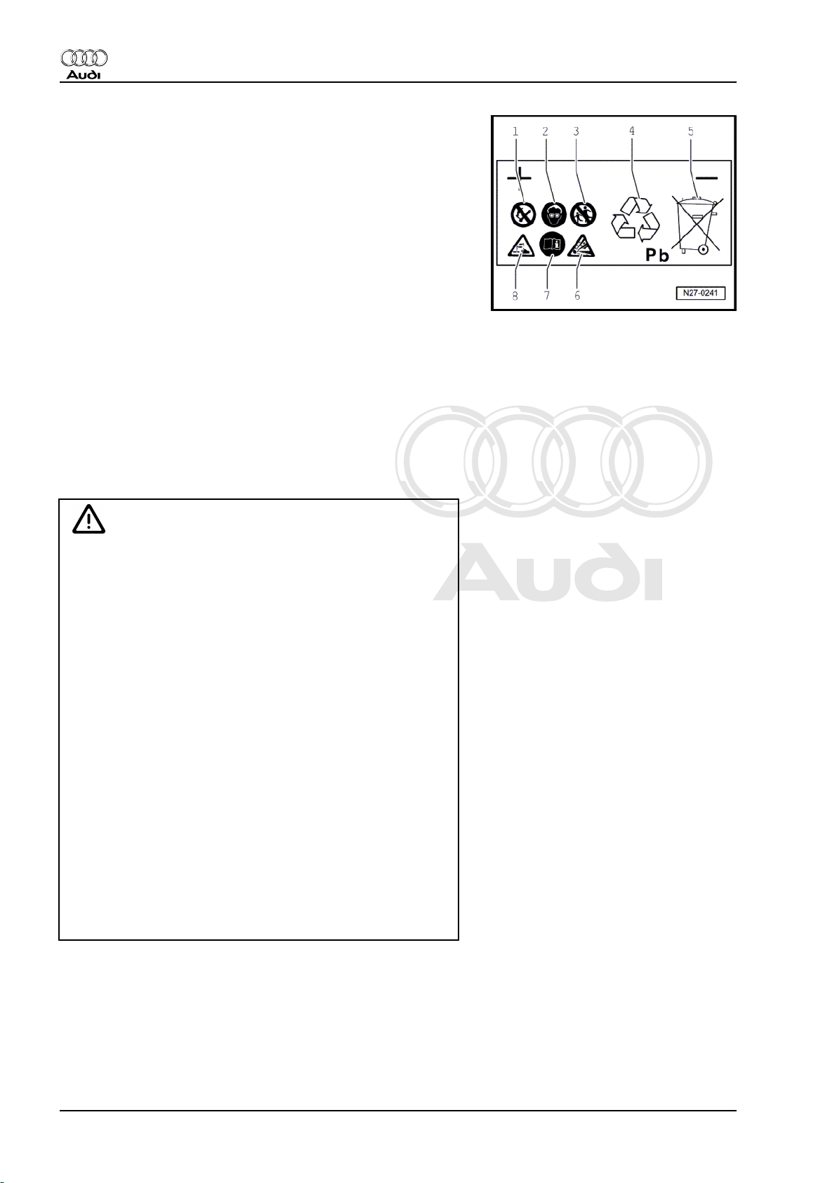
Explanatory notes on battery symbols
1 - Fires, sparks, naked flames and smoking are prohibited
when handling batteries. Avoid sparks and static discharge
when handling wires and electrical equipment. To avoid
short circuits, never place tools on the battery.
2 - Wear eye protection when working on the battery.
3 - Keep children away from acid and batteries.
4 - Disposal: Old batteries are hazardous waste. They are only
to be disposed of at an official collection point; all legal re‐
quirements must be observed.
5 - Do not dispose of old batteries with household waste.
6 - There is a risk of explosion when handling batteries. A highly
explosive gas mixture is given off when batteries are under
charge.
7 - Observe the instructions on the battery, in the Workshop
Manual „Electrical system; General information“ and in the
Owner's Manual.
8 - Danger of acid burns: Electrolyte is highly corrosive; pro‐
tective gloves and eye protection should therefore always
be worn when working on the battery. Do NOT tilt the battery
as electrolyte can leak out of the gas vents.
WARNING
Risk of injury due to electrolyte.
♦ Can cause severe injury to the eyes, skin and mucous
membranes.
♦ Inhalation can damage the respiratory system.
♦ Swallowing is harmful to the digestive system.
♦ First aid: Rinse eyes and immediately consult first aid sta‐
tion or inform doctor.
♦ Never tilt battery. Acid can leak out of the gas vents.
♦ Soak up spilt electrolyte with binding agent and neutralise
any residual electrolyte. Use e.g. soap solution for neu‐
tralising.
♦ Never allow electrolyte to come into contact with hands.
♦ Avoid contact with skin.
♦ Never touch mouth, nose or eyes with soiled hands.
♦ Immediately change any clothing affected by electrolyte
and place in water if necessary.
♦ Do not eat, drink or store foodstuffs at workplace.
♦ Wash thoroughly before breaks and on completion of
work.
2 Rep. gr.27 - Starter, current supply, CCS
Page 9
Protected by copyright. Copying for private or commercial purposes, in part or in whole, is not
permitted unless authorised by AUDI AG. AUDI AG does not guarantee or accept any liability
with respect to the correctness of information in this document. Copyright by AUDI AG.
Audi A1 2011 ➤ , Audi A2 2001 ➤ , Audi A3 2004 ➤ , Audi A4 2001 ➤ , Au ...
Electrical system; General information - Edition 10.2010
WARNING
Wear eye protection and protective clothing to reduce the risk
of injury.
♦ Wear safety goggles and an acid-resistant apron or alter‐
natively electrolyte-proof overalls.
♦ Wear electrolyte-proof gloves.
WARNING
Risk of explosion due to gas produced when charging battery.
♦ The gas given off during charging and sometimes emitted
by the battery at rest even after charging is explosive. In
the worst case, improper handling of the battery can lead
to explosion caused by escaping gas.
♦ Smoking, naked flames and sparks (caused by grinding,
welding or cutting) are prohibited when working in the vi‐
cinity of the battery.
♦ Take care to avoid short circuits when handling wires and
electrical equipment. Never place tools on the battery.
♦ To avoid sparks as a result of electrostatic discharge, al‐
ways touch the vehicle body before handling the battery.
WARNING
Avoid explosion risks.
♦ If the display is colourless or light yellow on batteries with
„magic eye“, do not check or charge the battery. Do NOT
boost start the vehicle. There is a risk of explosion when
checking or charging the battery or boost starting the ve‐
hicle. The battery must be renewed.
♦ Old batteries (in use for 6 months or more) must be treated
with an anti-static spray (currently „Neostatic Antistatikum
HB 155“) prior to handling.
♦ Sealing plugs of batteries which are not maintenance-free
must be firmly screwed in when charging.
♦ Charging of batteries removed from the vehicle is only
permitted in vented cubicles with extraction system.
♦ After charging, the battery must be left in the charging area
with extraction system for an appropriate length of time.
♦ Only work on batteries in suitable, well ventilated areas.
♦ Batteries must always be transported in conductive metal
containers.
♦ Do not use electrostatically chargeable materials for se‐
curing purposes.
1. Battery - general notes 3
Page 10
Protected by copyright. Copying for private or commercial purposes, in part or in whole, is not
permitted unless authorised by AUDI AG. AUDI AG does not guarantee or accept any liability
with respect to the correctness of information in this document. Copyright by AUDI AG.
Audi A1 2011 ➤ , Audi A2 2001 ➤ , Audi A3 2004 ➤ , Audi A4 2001 ➤ , Au ...
Electrical system; General information - Edition 10.2010
WARNING
Risk of damage to vehicle.
♦ Escaping electrolyte could cause acid corrosion and dam‐
age to safety-relevant vehicle components.
WARNING
Risk of environmental pollution.
♦ Old batteries are hazardous waste. They contain toxic
lead (Pb) and sulphuric acid.
♦ Observe disposal regulations. Old batteries should only
be disposed of in appropriate containers at an official col‐
lection point.
4 Rep. gr.27 - Starter, current supply, CCS
Page 11
Protected by copyright. Copying for private or commercial purposes, in part or in whole, is not
permitted unless authorised by AUDI AG. AUDI AG does not guarantee or accept any liability
with respect to the correctness of information in this document. Copyright by AUDI AG.
Audi A1 2011 ➤ , Audi A2 2001 ➤ , Audi A3 2004 ➤ , Audi A4 2001 ➤ , Au ...
Electrical system; General information - Edition 10.2010
2 Non maintenance-free batteries
(without „magic eye“)
Lead-acid batteries which are not maintenance-free are filled with
liquid electrolyte (wet battery). They are fitted with sealing plugs.
WARNING
Risk of injury when handling electrolyte.
♦ Observe warnings and safety regulations ⇒ page 2 .
Risk of explosion due to gas produced when charging battery.
♦ Observe warnings and safety regulations ⇒ page 3 .
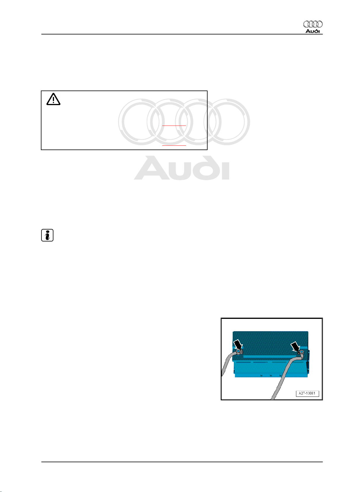
2.1 Central gas venting system
To prevent the gas produced when charging the battery from
causing damage or becoming a health hazard, the gas is dis‐
charged through a central opening in the top of the battery cover.
– Make sure that the central gas venting system hose or pipe is
always attached to the battery.
– Make sure the central gas venting system hose or pipe is not
obstructed. Only then is the battery able to vent freely.
Note
More modern batteries are equipped with a fine-mesh flame trap
at the central gas venting outlet. This circular glass-fibre mesh
with a diameter of approx. 15 mm and a thickness of 2 mm oper‐
ates like a valve. It allows the gas given off during battery charging
to escape and at the same time prevents ignition of the explosive
gas in the battery.
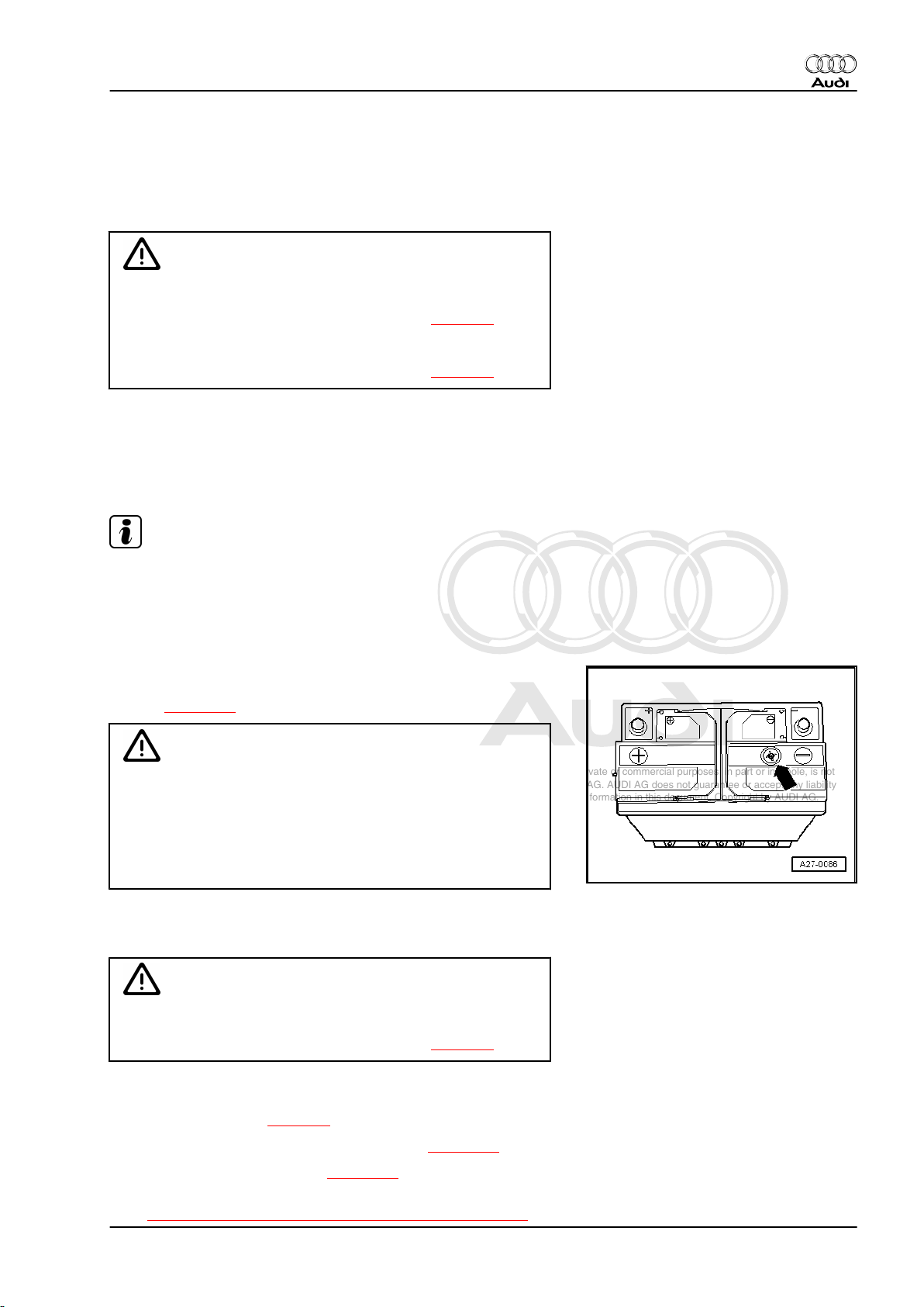
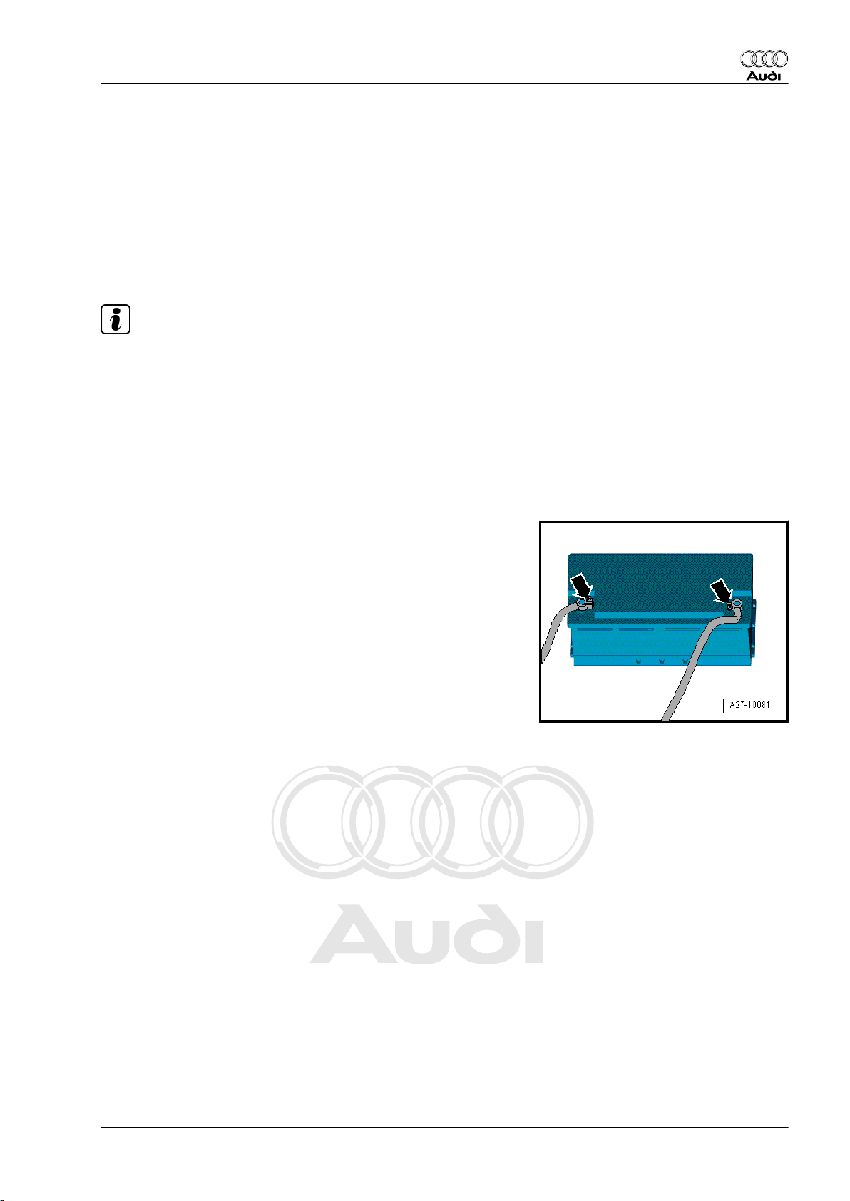
2.2 Battery terminal screw connection
Observe the following to avoid damaging the battery terminals
and battery housing:
♦ Battery terminal posts must not be greased.
♦ Only connect battery terminal clamps -arrows- by hand without
exerting force.
♦ Fit battery terminal clamps in such a way that the battery ter‐
minal post is flush with the terminal clamp or protrudes from it.
♦ Tightening torque for battery terminal clamps and additional
clamps ⇒ Electrical system; Rep. gr. 27 .
♦ Never re-tighten screw connections after tightening battery
terminal clamps to specified torque.
2. Non maintenance-free batteries (without „magic eye“) 5
Page 12
Protected by copyright. Copying for private or commercial purposes, in part or in whole, is not
permitted unless authorised by AUDI AG. AUDI AG does not guarantee or accept any liability
with respect to the correctness of information in this document. Copyright by AUDI AG.
Audi A1 2011 ➤ , Audi A2 2001 ➤ , Audi A3 2004 ➤ , Audi A4 2001 ➤ , Au ...
Electrical system; General information - Edition 10.2010
2.3 Checking non maintenance-free batter‐
ies
WARNING
Risk of injury and explosion.
♦ Observe warnings and safety regulations ⇒ page 1 .
Perform tests in the following order:
1. Visual inspection ⇒ page 6
2. Checking electrolyte level ⇒ page 7
3. Checking battery using battery tester with printer -
VAS 6161- ⇒ page 17 or using battery tester with printer
-VAS 5097A- ⇒ page 21 or measuring relative density of
electrolyte ⇒ page 7 .
4. Further procedure depending on result of battery check us‐
ing battery tester.
2.4 Visual inspection of battery
– Visually inspect battery before performing comprehensive
measurements:
♦ External condition of battery
♦ Battery connections
♦ Secure fit of battery
Caution
Risk of explosion, poor crash safety, risk of corrosion, short‐
ened service life.
♦ If the retainer plate is loose, this may damage the battery
housing and allow electrolyte to escape.
♦ If not properly secured, the battery may be subject to vi‐
bration damage and the plates in the battery will be dam‐
aged.
♦ Tighten bolt for retainer plate; for tightening torque refer to
⇒ Electrical system; Rep. gr. 27 .
Risk of malfunctions in electrical system or cable fire.
♦ The wiring connections may not make proper contact if the
battery terminals are damaged or the battery terminal
clamps are loose. Check condition of battery terminals; for
tightening torques for battery terminal clamps and addi‐
tional clamps refer to ⇒ Electrical system; Rep. gr. 27 .
♦ Risk of corrosion due to escaping electrolyte.
♦ The battery openings must be fitted with the correct type
of genuine sealing plugs to ensure proper sealing of the
battery cover (different types). Only use genuine sealing
plugs of the same type when renewing missing or dam‐
aged sealing plugs.
♦ The plugs must be fitted with an O-ring.
6 Rep. gr.27 - Starter, current supply, CCS
Page 13
Protected by copyright. Copying for private or commercial purposes, in part or in whole, is not
permitted unless authorised by AUDI AG. AUDI AG does not guarantee or accept any liability
with respect to the correctness of information in this document. Copyright by AUDI AG.
Audi A1 2011 ➤ , Audi A2 2001 ➤ , Audi A3 2004 ➤ , Audi A4 2001 ➤ , Au ...
Electrical system; General information - Edition 10.2010
2.5 Checking electrolyte level in battery
Procedure
The correct electrolyte level is an important factor in ensuring long
battery service life.
WARNING
Risk of injury when handling electrolyte.
♦ Observe safety instructions when handling battery elec‐
trolyte ⇒ page 2 .
♦ Wear eye protection and protective clothing ⇒ page 3 .
Risk of explosion due to naked flames, fires and smoking.
♦ Use only an electric hand torch to illuminate the inside of
the battery housing.
♦ Never illuminate the inside of the battery housing with a
naked flame.
♦ Never bring a naked flame or a burning cigarette into the
vicinity of the battery.
– If the „min“ and „max“ marks are visible on the outside of the
battery, only perform an external visual inspection.
• The electrolyte level must be above the „min“ mark, but may
not exceed the „max“ mark.
– If it is difficult to detect the „min“ and „max“ marks on the out‐
side of the battery or they cannot be seen through the battery
housing , unscrew the sealing plugs.
– Check the electrolyte level by making a visual inspection of the
inside of the battery.
• The electrolyte level must coincide with the internal level mark
(plastic moulding). This corresponds to the „max“ marking on
the outside.
Caution
Risk of corrosion due to escaping electrolyte.
♦ The battery openings must be fitted with the correct type
of genuine sealing plugs to ensure proper sealing of the
battery cover (different types). Only use genuine sealing
plugs of the same type when renewing missing or dam‐
aged sealing plugs.
♦ The plugs must be fitted with an O-ring.
♦ If the electrolyte level is too low, the battery must be re‐
newed. Do not top up with distilled water.
– Screw sealing plugs of battery cells back in again.
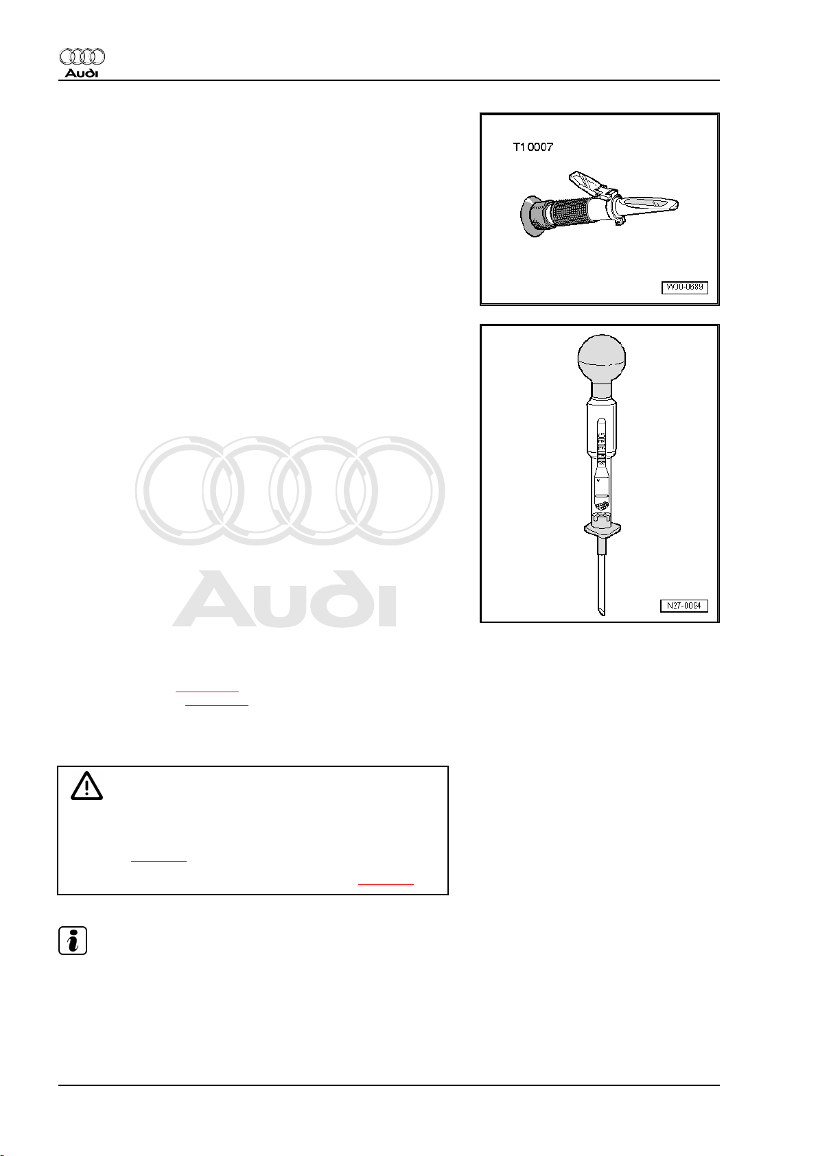
2.6 Measuring relative density of electrolyte
in all battery cells
Special tools and workshop equipment required
2. Non maintenance-free batteries (without „magic eye“) 7
Page 14
Protected by copyright. Copying for private or commercial purposes, in part or in whole, is not
permitted unless authorised by AUDI AG. AUDI AG does not guarantee or accept any liability
with respect to the correctness of information in this document. Copyright by AUDI AG.
Audi A1 2011 ➤ , Audi A2 2001 ➤ , Audi A3 2004 ➤ , Audi A4 2001 ➤ , Au ...
Electrical system; General information - Edition 10.2010
♦ Refractometer -T10007- or
♦ Hydrometer (commercially available)
Procedure
In conjunction with the battery check using the battery tester with
printer -VAS 6161- ⇒ page 17 or using the battery tester with
printer -VAS 5097A- ⇒ page 21 , the relative density test pro‐
vides information on the charge state of the battery.
• The temperature of the battery electrolyte must be at least +10
°C.
WARNING
Risk of injury when handling electrolyte.
♦ Observe safety instructions when handling battery elec‐
trolyte ⇒ page 2 .
♦ Wear eye protection and protective clothing ⇒ page 3 .
Note
The relative density of the electrolyte can be checked immediately
after charging the battery.
– Unscrew all battery cell sealing plugs.
8 Rep. gr.27 - Starter, current supply, CCS
Page 15
Protected by copyright. Copying for private or commercial purposes, in part or in whole, is not
permitted unless authorised by AUDI AG. AUDI AG does not guarantee or accept any liability
with respect to the correctness of information in this document. Copyright by AUDI AG.
Audi A1 2011 ➤ , Audi A2 2001 ➤ , Audi A3 2004 ➤ , Audi A4 2001 ➤ , Au ...
Electrical system; General information - Edition 10.2010
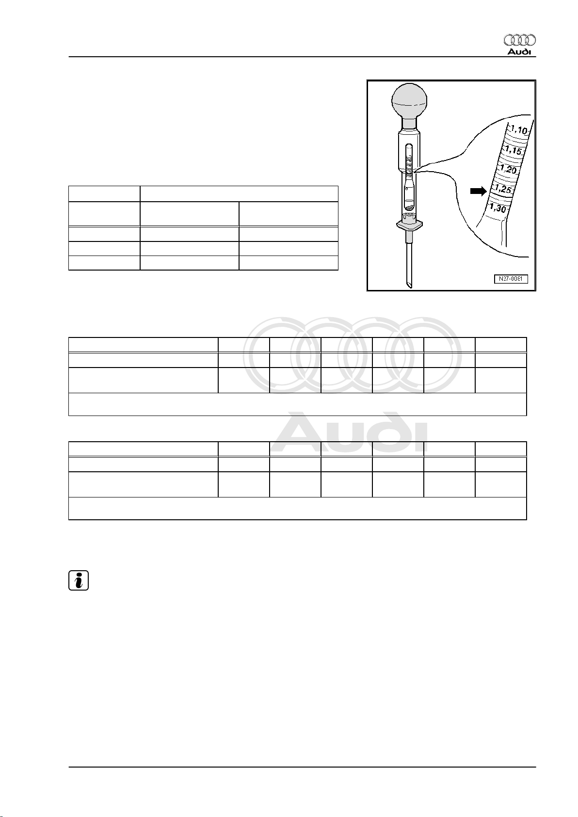
– Dip hydrometer into battery cell and draw in electrolyte until
the float is floating freely in the electrolyte.
♦ The greater the relative density of the electrolyte drawn in, the
higher the float will ride.
♦
The relative density in kg/dm3 (specific density of electrolyte)
can be read off the hydrometer scale.
– Take reading on hydrometer and compare it to values given
in table:
Charge state
Relative density of electrolyte in kg/dm
In normal climatic
In tropical countries
3
zones
discharged 1.12 1.08
half charged 1.20 1.16
well charged 1.28 1.23
The relative density in normal climatic zones must be at least 1.24
kg/dm3. If relative density is too low in all battery cells:
– Charge battery and then repeat electrolyte relative density
test.
Example 1
Battery cell 1 2 3 4 5 6
Relative density per battery cell in
3
kg/dm
1)
•
Relative density in battery cell 4 is too low (difference greater than 0.03 kg/dm3).
Example 2
Battery cell 1 2 3 4 5 6
Relative density per battery cell in
3
kg/dm
1)
•
Relative density in battery cells 4 and 5 is too low (difference greater than 0.03 kg/dm3).
1.24 1.25 1.25
1.26 1.26 1.25
1.10
1.14
1)
1)
1.24 1.25
1)
1.18
1.24
– Renew the battery if the specified values are not attained.
Note
The battery must be renewed if the relative density of the elec‐
trolyte measured in the individual battery cells varies by more than
0.03 kg/dm3.
2. Non maintenance-free batteries (without „magic eye“) 9
Page 16
Protected by copyright. Copying for private or commercial purposes, in part or in whole, is not
permitted unless authorised by AUDI AG. AUDI AG does not guarantee or accept any liability
with respect to the correctness of information in this document. Copyright by AUDI AG.
Audi A1 2011 ➤ , Audi A2 2001 ➤ , Audi A3 2004 ➤ , Audi A4 2001 ➤ , Au ...
Electrical system; General information - Edition 10.2010
Caution
Danger from escaping electrolyte.
♦ The battery openings must be fitted with the correct type
of genuine sealing plugs to ensure proper sealing of the
battery cover (different types). Only use genuine sealing
plugs of the same type when renewing missing or dam‐
aged sealing plugs.
♦ The plugs must be fitted with an O-ring.
– If specified values have been attained, screw sealing plugs of
battery cells back in.
Note
Observe disposal regulations if battery has to be renewed
⇒ page 4 .
10 Rep. gr.27 - Starter, current supply, CCS
Page 17
Protected by copyright. Copying for private or commercial purposes, in part or in whole, is not
permitted unless authorised by AUDI AG. AUDI AG does not guarantee or accept any liability
with respect to the correctness of information in this document. Copyright by AUDI AG.
Audi A1 2011 ➤ , Audi A2 2001 ➤ , Audi A3 2004 ➤ , Audi A4 2001 ➤ , Au ...
Electrical system; General information - Edition 10.2010
3 Maintenance-free batteries
Only install maintenance-free batteries with the specifications
„TL82506“ (from December 1997 onwards) and „VW75073“ (from
August 2001 onwards).
WARNING
Risk of injury when handling electrolyte.
♦ Observe warnings and safety regulations ⇒ page 2 .
Risk of explosion due to gas produced when charging battery.
♦ Observe warnings and safety regulations ⇒ page 3 .
3.1 Battery with „magic eye“
Lead-acid batteries with „magic eye“ are filled with liquid electro‐
lyte (wet battery). They are not fitted with sealing plugs for topping
up with distilled water.
Note
♦
If batteries with „magic eye“ are fitted with sealing plugs for
production reasons, these are covered with plastic foil.
♦
Do not remove plastic foil and do not top up with distilled water.
♦
Only perform visual inspections.
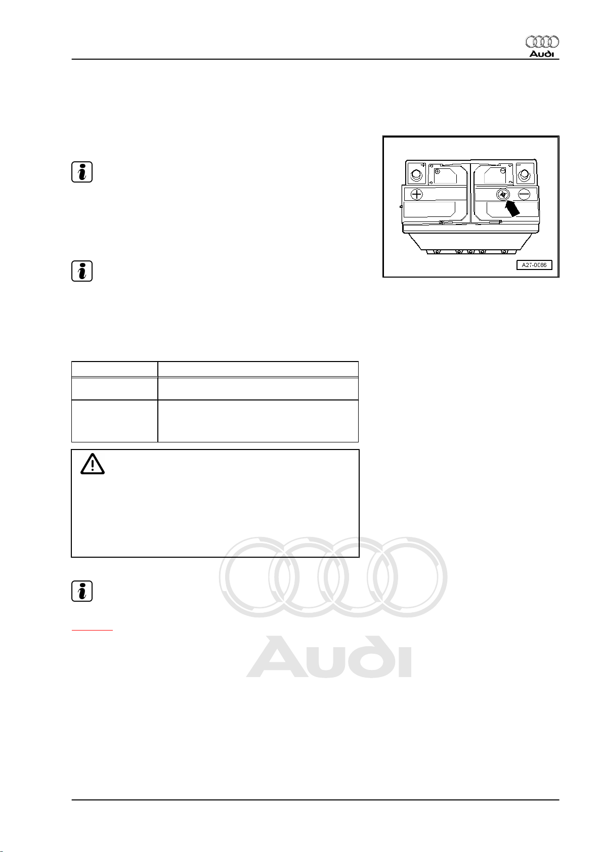
The „magic eye“ -arrow- provides information on the electrolyte
level and battery charge via a colour indicator. Possible indicator
colours ⇒ page 11 .
WARNING
Risk of explosion due to a discharged battery with „magic eye“.
♦ The battery must NOT be checked or charged if the indi‐
cator of the „magic eye“ is colourless or yellow. Do NOT
boost start the vehicle. There is a risk of explosion when
checking or charging the battery or boost starting the ve‐
hicle. The battery must be renewed.
3.2 Checking battery with „magic eye“
WARNING
Risk of injury and explosion.
♦ Observe warnings and safety regulations ⇒ page 1 .
Perform tests in the following order:
1. Visual inspection ⇒ page 6
2. Checking colour indicator of „magic eye“ ⇒ page 15
3. Checking electrolyte level ⇒ page 15
4. Checking battery
⇒ „4 Checking battery - vehicles without battery monitor
3. Maintenance-free batteries 11
Page 18
Protected by copyright. Copying for private or commercial purposes, in part or in whole, is not
permitted unless authorised by AUDI AG. AUDI AG does not guarantee or accept any liability
with respect to the correctness of information in this document. Copyright by AUDI AG.
Audi A1 2011 ➤ , Audi A2 2001 ➤ , Audi A3 2004 ➤ , Audi A4 2001 ➤ , Au ...
Electrical system; General information - Edition 10.2010
control unit J367 or energy management control unit J644
“, page 17 or
⇒ „5.2 Checking battery by measuring current draw - vehi‐
cles with battery monitor control unit J367 or energy man‐
agement control unit J644 “, page 30 .
5. Further procedure depending on result of battery check us‐
ing battery tester.
3.3 Valve-regulated lead acid (VRLA) or ab‐
sorbent glass mat (AGM) battery without
„magic eye“
♦ VLRA or AGM batteries are deep-cycle resistant and leak-
proof.
♦ VRLA or AGM batteries are filled with electrolyte which is held
in place in an „A“bsorbent „G“lass „M“at. The battery is sealed
and equipped with valves.
♦ As the electrolyte is absorbed in the mat, these batteries can‐
not have a „magic eye“. Absorbent glass mat batteries are
marked with „AGM“ on the battery.
Note
♦
VLRA or AGM batteries cannot and must not be opened and
must not be topped up with distilled water.
♦
Only perform visual inspections.
Caution
Fitting a wrong battery will result in poor crash safety.
♦ If a vehicle was originally equipped with a VRLA or AGM
battery, only replace the battery with another VRLA or
AGM battery.
3.4 Checking valve-regulated lead acid or
AGM battery
WARNING
Risk of injury and explosion.
♦ Observe warnings and safety regulations ⇒ page 1 .
Perform tests in the following order:
1. Visual inspection ⇒ page 6
2. Checking battery
⇒ „4 Checking battery - vehicles without battery monitor
control unit J367 or energy management control unit J644
“, page 17 or
⇒ „5.2 Checking battery by measuring current draw - vehi‐
cles with battery monitor control unit J367 or energy man‐
agement control unit J644 “, page 30 .
3. Further procedure depending on result of battery check us‐
ing battery tester.
12 Rep. gr.27 - Starter, current supply, CCS
Page 19
Protected by copyright. Copying for private or commercial purposes, in part or in whole, is not
permitted unless authorised by AUDI AG. AUDI AG does not guarantee or accept any liability
with respect to the correctness of information in this document. Copyright by AUDI AG.
Audi A1 2011 ➤ , Audi A2 2001 ➤ , Audi A3 2004 ➤ , Audi A4 2001 ➤ , Au ...
Electrical system; General information - Edition 10.2010
3.5 Central gas venting system
To prevent the gas produced when charging the battery from
causing damage or becoming a health hazard in the engine or
passenger compartment, the gas is discharged through a central
opening in the top of the battery cover.
– Make sure that the central gas venting system hose or pipe is
always attached to the battery.
– Make sure the central gas venting system hose or pipe is not
obstructed. Only then is the battery able to vent freely.
Note
More modern batteries are equipped with a fine-mesh flame trap
at the central gas venting outlet. This circular glass-fibre mesh
with a diameter of approx. 15 mm and a thickness of 2 mm oper‐
ates like a valve. It allows the gas given off during battery charging
to escape and at the same time prevents ignition of the explosive
gas in the battery.
3.6 Battery terminal screw connection
Observe the following to avoid damaging the battery terminals
and battery housing:
♦ Battery terminal posts must not be greased.
♦ Only connect battery terminal clamps -arrows- by hand without
exerting force.
♦ Fit battery terminal clamps in such a way that the battery ter‐
minal post is flush with the terminal clamp or protrudes from it.
♦ Tightening torque for battery terminal clamps and additional
clamps ⇒ Electrical system; Rep. gr. 27 .
♦ Never re-tighten screw connections after tightening battery
terminal clamps to specified torque.
3.7 Visual inspection of battery
– Visually inspect battery before performing comprehensive
measurements:
♦ External condition of battery
♦ Battery connections
♦ Secure fit of battery
3. Maintenance-free batteries 13
Page 20
Protected by copyright. Copying for private or commercial purposes, in part or in whole, is not
permitted unless authorised by AUDI AG. AUDI AG does not guarantee or accept any liability
with respect to the correctness of information in this document. Copyright by AUDI AG.
Audi A1 2011 ➤ , Audi A2 2001 ➤ , Audi A3 2004 ➤ , Audi A4 2001 ➤ , Au ...
Electrical system; General information - Edition 10.2010
Caution
Risk of explosion, poor crash safety, risk of corrosion, short‐
ened service life.
♦ If the retainer plate is loose, this may damage the battery
housing and allow electrolyte to escape.
♦ If not properly secured, the battery may be subject to vi‐
bration damage and the plates in the battery will be dam‐
aged.
♦ Tighten bolt for retainer plate; for tightening torque refer to
⇒ Electrical system; Rep. gr. 27 .
Risk of malfunctions in electrical system or cable fire.
♦ The wiring connections may not make proper contact if the
battery terminals are damaged or the battery terminal
clamps are loose. Check condition of battery terminals; for
tightening torques for battery terminal clamps and addi‐
tional clamps refer to ⇒ Electrical system; Rep. gr. 27 .
14 Rep. gr.27 - Starter, current supply, CCS
Page 21
Protected by copyright. Copying for private or commercial purposes, in part or in whole, is not
permitted unless authorised by AUDI AG. AUDI AG does not guarantee or accept any liability
with respect to the correctness of information in this document. Copyright by AUDI AG.
Audi A1 2011 ➤ , Audi A2 2001 ➤ , Audi A3 2004 ➤ , Audi A4 2001 ➤ , Au ...
Electrical system; General information - Edition 10.2010
3.8 Checking colour indicator (electrolyte level in battery) - batteries with „magic eye“
Procedure
Note
As the „magic eye“ is only located in one battery cell, the electro‐
lyte level is only checked for this battery cell.
– Prior to visual inspection, use a screwdriver handle to tap gen‐
tly and carefully on the magic eye -arrow-.
Note
When charging the battery and while driving, air bubbles may
form under the „magic eye“ and falsify the colour indicator. Tap‐
ping on the „magic eye“ will disperse the air bubbles underneath.
– Read off electrolyte level in battery from colour indicator. Two
different displays are possible:
Colour indicator Battery charge state
Black or green • Electrolyte level in battery OK
Colourless or light
yellow
WARNING
• Electrolyte level in battery too low. Risk of
explosion; do not check or charge bat‐
tery.
Risk of explosion due to a discharged battery with „magic eye“.
♦ The battery must NOT be checked or charged if the indi‐
cator of the „magic eye“ is colourless or yellow. Do NOT
boost start the vehicle. There is a risk of explosion when
checking or charging the battery or boost starting the ve‐
hicle. The battery must be renewed.
Note
Observe disposal regulations if battery has to be renewed
⇒ page 4 .
3.9 Checking electrolyte level in battery
Procedure
The correct electrolyte level is an important factor in ensuring long
battery service life.
3. Maintenance-free batteries 15
Page 22
Protected by copyright. Copying for private or commercial purposes, in part or in whole, is not
permitted unless authorised by AUDI AG. AUDI AG does not guarantee or accept any liability
with respect to the correctness of information in this document. Copyright by AUDI AG.
Audi A1 2011 ➤ , Audi A2 2001 ➤ , Audi A3 2004 ➤ , Audi A4 2001 ➤ , Au ...
Electrical system; General information - Edition 10.2010
WARNING
Danger of injury when handling electrolyte.
♦ Observe safety instructions when handling battery elec‐
trolyte ⇒ page 2 .
♦ Wear eye protection and protective clothing ⇒ page 3 .
♦ If the electrolyte level is too low, the battery must be re‐
newed. Do not open battery and do not top up with distilled
water.
Risk of explosion due to naked flames, fires and smoking.
♦ Never bring a naked flame or a burning cigarette into the
vicinity of the battery.
– If the „min“ and „max“ marks are visible on the outside of the
battery, perform an external visual inspection.
• The electrolyte level must be above the „min“ mark, but may
not exceed the „max“ mark.
16 Rep. gr.27 - Starter, current supply, CCS
Page 23
Protected by copyright. Copying for private or commercial purposes, in part or in whole, is not
permitted unless authorised by AUDI AG. AUDI AG does not guarantee or accept any liability
with respect to the correctness of information in this document. Copyright by AUDI AG.
Audi A1 2011 ➤ , Audi A2 2001 ➤ , Audi A3 2004 ➤ , Audi A4 2001 ➤ , Au ...
Electrical system; General information - Edition 10.2010
4 Checking battery - vehicles without
battery monitor control unit -J367- or
energy management control unit J644-
Do not open maintenance-free batteries; this would invalidate the
warranty.
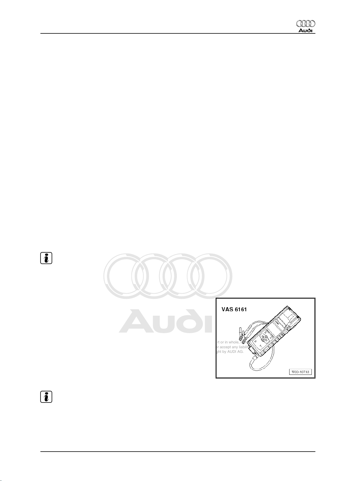
4.1 Checking battery using battery tester with printer -VAS 6161-
♦ When checking the battery using battery tester with printer -
VAS 6161- it is not necessary to disconnect the battery earth
cable.
♦ The battery tester with printer -VAS 6161- no longer puts the
battery under load, but works by measuring the dynamic con‐
ductivity. For this reason it is possible to perform several
measurements without re-charging the battery.
♦ No-load voltage measurement can be performed without de‐
lay.
♦ All types of battery are stored in the tester and they can be
updated.
♦ The battery bar code can be read off directly with the optionally
available 2D scanner.
♦ The integrated temperature sensor improves the quality of
measurements.
♦ Data can be stored on an SD card.
Note
For information on battery tester with printer, refer to ⇒ Instruction
Manual for -VAS 6161- .
Special tools and workshop equipment required
♦ Battery tester with printer -VAS 6161-
Note
For information on how to use the battery tester, refer to ⇒ In‐
struction Manual for -VAS 6161- .
Procedure
• Battery temperature must be at least +10 °C.
4. Checking battery - vehicles without battery monitor control unit J367 or energy management control unit J644 17
Page 24
Protected by copyright. Copying for private or commercial purposes, in part or in whole, is not
permitted unless authorised by AUDI AG. AUDI AG does not guarantee or accept any liability
with respect to the correctness of information in this document. Copyright by AUDI AG.
Audi A1 2011 ➤ , Audi A2 2001 ➤ , Audi A3 2004 ➤ , Audi A4 2001 ➤ , Au ...
Electrical system; General information - Edition 10.2010
WARNING
Risk of injury due to electrolyte.
♦ Observe safety instructions when handling battery elec‐
trolyte ⇒ page 2 .
♦ Wear eye protection and protective clothing ⇒ page 3 .
♦ Sealing plugs of batteries which are not maintenance-free
must be firmly screwed in when measuring voltage under
load.
Risk of explosion due to a discharged battery with „magic eye“.
♦ The battery must NOT be checked or charged if the indi‐
cator of the „magic eye“ is colourless or yellow. Do NOT
boost start the vehicle. There is a risk of explosion when
checking or charging the battery or boost starting the ve‐
hicle. The battery must be renewed.
– Switch off ignition and all electrical equipment.
– Check colour indicator of batteries with „magic eye“
⇒ page 15 .
– Switch on battery tester with printer -VAS 6161- .
– Connect red test clamp „+“ of battery tester to positive battery
terminal or jump start terminal in engine compartment.
– Connect black test clamp „–“ of battery tester to negative ter‐
minal of battery or jump start terminal in engine compartment.
Note
Make sure the test clamps make proper contact.
– Select one of the following functions:
♦ Maintenance test
♦ Service test
♦ Warranty test
Maintenance test
– Select „maintenance test“ from the menu.
– Connect scanner and scan in vehicle identification number.
– Select connection point: „at battery post“ or „at jump start
post“.
– Select vehicle model.
– Scan in battery bar code.
– Determine temperature by holding temperature sensor at a
distance of approx. 5 cm over battery or jump start post until
a constant temperature is displayed.
– Start test.
– If required, print out test log.
Service test
– Select „service test“ from the menu.
– Select vehicle model.
18 Rep. gr.27 - Starter, current supply, CCS
Page 25

Protected by copyright. Copying for private or commercial purposes, in part or in whole, is not
permitted unless authorised by AUDI AG. AUDI AG does not guarantee or accept any liability
with respect to the correctness of information in this document. Copyright by AUDI AG.
Audi A1 2011 ➤ , Audi A2 2001 ➤ , Audi A3 2004 ➤ , Audi A4 2001 ➤ , Au ...
Electrical system; General information - Edition 10.2010
– Determine temperature by holding temperature sensor at a
distance of approx. 5 cm over battery until a constant temper‐
ature is displayed.
– Select type of battery: „regular“, „AGM“, „2*6V“ or „Gel“.
– Select rating units: „CCA“, „JIS“, „DIN“, „SAE“, „IEC“ or „EN“.
– Start test.
– If required, print out test log.
Warranty test
– Select „warranty test“ from the menu.
– Select fitting location: „in vehicle“ or „out of vehicle“.
– Select vehicle model.
– Determine temperature by holding temperature sensor at a
distance of approx. 5 cm over battery until a constant temper‐
ature is displayed.
– Select type of battery: „regular“, „AGM“, „2*6V“ or „Gel“.
– Select corresponding rating using arrow buttons.
– Start test.
– If required, print out test log.
Note
The test log is required for warranty processing.
– Switch off battery tester.
– Detach test clamps.
4. Checking battery - vehicles without battery monitor control unit J367 or energy management control unit J644 19
Page 26
Protected by copyright. Copying for private or commercial purposes, in part or in whole, is not
permitted unless authorised by AUDI AG. AUDI AG does not guarantee or accept any liability
with respect to the correctness of information in this document. Copyright by AUDI AG.
Audi A1 2011 ➤ , Audi A2 2001 ➤ , Audi A3 2004 ➤ , Audi A4 2001 ➤ , Au ...
Electrical system; General information - Edition 10.2010
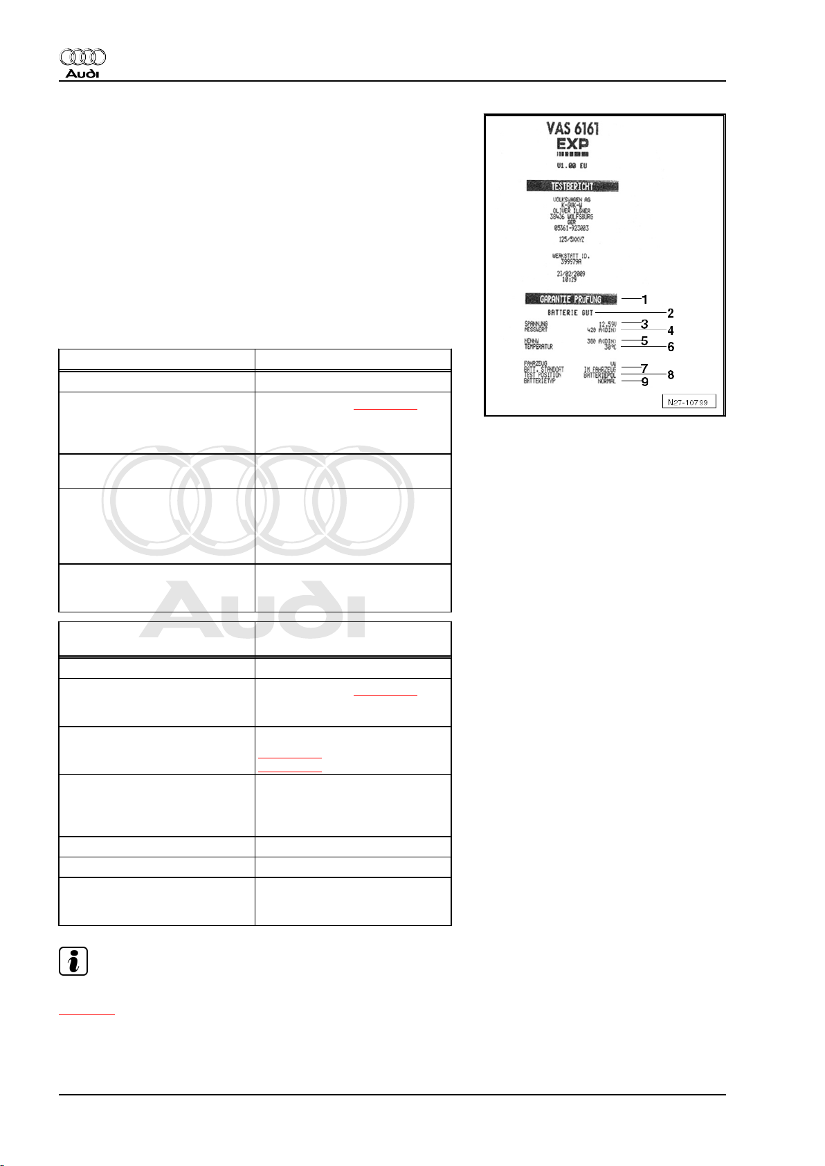
Test result on printout:
1 - Test mode
2 - Test result
3 - Voltage measured
4 - Nominal value of battery measured
5 - Nominal value of battery as set on tester
6 - Temperature measured above battery
7 - Fitting location of battery
8 - Position of battery clamp as set on tester
9 - Type of battery set
Test result of maintenance test Measures
Good battery Battery OK
Charge battery immediately Charge battery ⇒ page 35
and test again. Faults can occur
if battery is not fully charged
and tested again
Mark as defective Mark as „defective“ and remove
from vehicle
Check tester connection Disconnect battery and test
again. Poor contact of the ca‐
bles can be responsible for the
result „Check tester connec‐
tion“
Check connection Cable must be connected di‐
rectly to battery and not to jump
start post
Test result of service test and
Measures
warranty test
Good battery Battery OK
Good battery - recharge Charge battery ⇒ page 35 ,
trace cause of fault responsible
for discharging, if necessary
Perform current draw test Perform current draw test
⇒ page 26 . Charge battery
⇒ page 35 and test again
Replace battery Disconnect battery and test
again. Poor contact of the ca‐
bles can be responsible for the
result "Replace battery"
Bad cell - replace Replace battery
Frozen battery Thaw battery and test again
Check connection Cable must be connected di‐
rectly to battery and not to jump
start post
Note
Observe disposal regulations if battery has to be renewed
⇒ page 4 .
20 Rep. gr.27 - Starter, current supply, CCS
Page 27
Protected by copyright. Copying for private or commercial purposes, in part or in whole, is not
permitted unless authorised by AUDI AG. AUDI AG does not guarantee or accept any liability
with respect to the correctness of information in this document. Copyright by AUDI AG.
Audi A1 2011 ➤ , Audi A2 2001 ➤ , Audi A3 2004 ➤ , Audi A4 2001 ➤ , Au ...
Electrical system; General information - Edition 10.2010
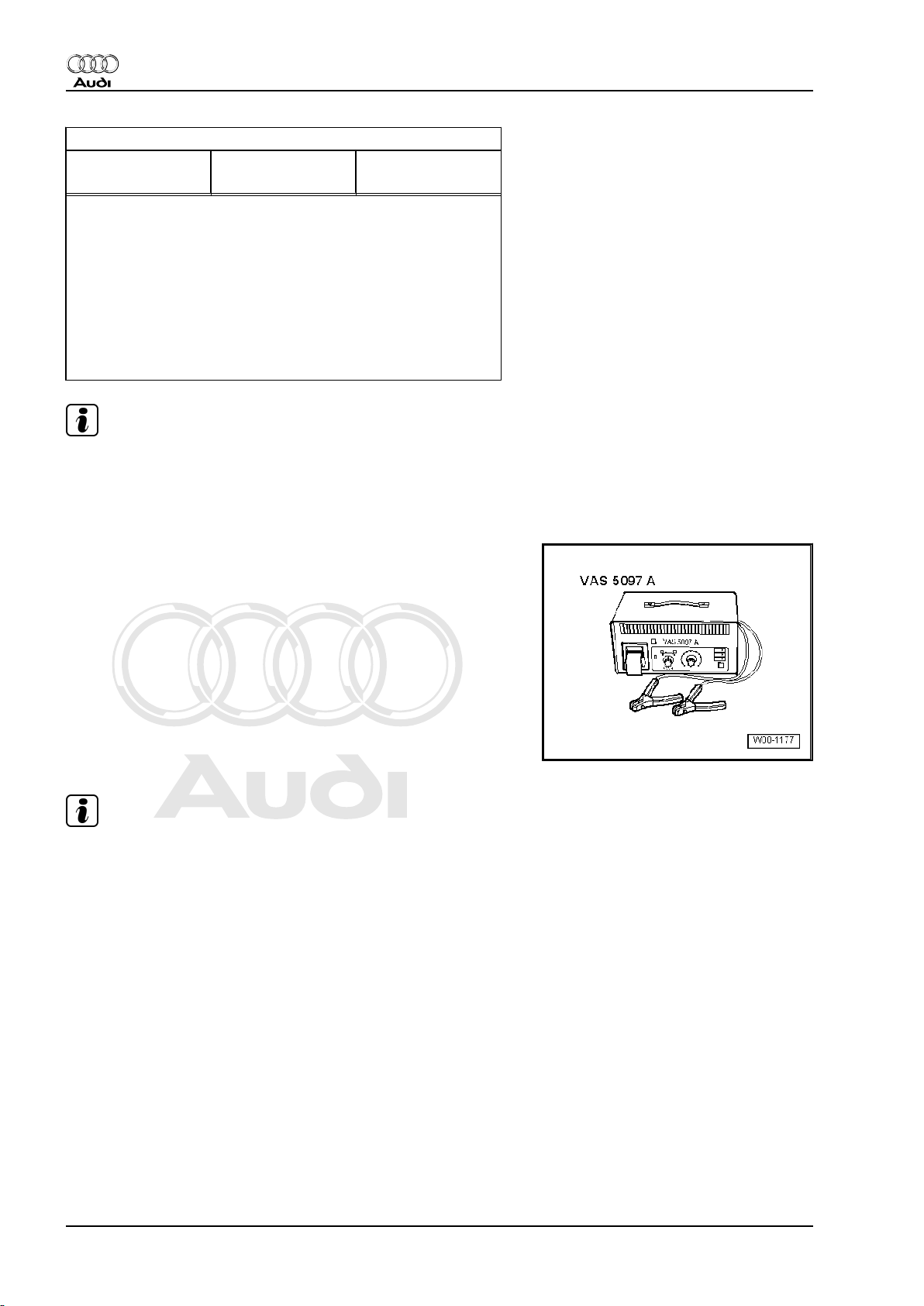
4.2 Checking battery using battery tester with printer -VAS 5097A-
♦ Measuring voltage under load simulates starting engine at low
temperatures. During the test, a high current flows through the
battery, causing the voltage to drop. The amount of the voltage
drop will depend on the state of charge of the battery. The
voltage must not fall below the minimum value specified by the
battery tester.
♦ After the test, the voltage will remain at a low level for a long
time, rising only slowly.
♦ If the battery is defective or only weakly charged, the battery
voltage will drop very rapidly below the specified minimum
voltage level.
♦ The battery must be renewed if the voltage drops below the
specified minimum level.
♦ Only perform the test once. Repeating the test would falsify
the result.
♦ The battery tester must be allowed to cool down for approxi‐
mately 30 minutes before checking another battery.
The battery tester with printer -VAS 5097 A- can be used to check
12 V batteries with the following low temperature test currents:
Low temperature test current in A (Ampere)
1)
According to DIN
2)
According to EN /
3)
SAE
According to IEC
80 – 104 136 – 177 95 – 124
105 – 129 178 – 219 125 – 154
130 – 154 220 – 261 155 – 184
155 – 179 262 – 303 185 – 214
180 – 204 304 – 345 215 – 244
204 – 229 346 – 387 245 – 274
230 – 254 388 – 429 275 – 304
255 – 279 430 – 471 305 – 334
280 – 304 472 – 513 335 – 364
305 –329 514 – 555 365 – 394
330 – 354 556 – 597 395 – 424
355 – 379 598 – 639 425 – 454
380 – 389 640 – 657 455 – 464
390 – 399 658 – 675 465 – 474
400 – 409 676 – 693 475 – 484
410 – 419 694 – 711 485 – 494
420 – 429 712 – 729 495 – 504
430 – 439 730 – 747 505 – 514
440 – 449 748 – 765 515 – 524
450 – 459 766 – 783 525 – 534
460 – 469 784 – 801 535 – 544
470 – 479 802 – 819 545 – 554
480 – 489 820 – 837 555 – 564
490 – 499
4)
838 – 855 565 – 574
4)
4. Checking battery - vehicles without battery monitor control unit J367 or energy management control unit J644 21
Page 28
Protected by copyright. Copying for private or commercial purposes, in part or in whole, is not
permitted unless authorised by AUDI AG. AUDI AG does not guarantee or accept any liability
with respect to the correctness of information in this document. Copyright by AUDI AG.
Audi A1 2011 ➤ , Audi A2 2001 ➤ , Audi A3 2004 ➤ , Audi A4 2001 ➤ , Au ...
Electrical system; General information - Edition 10.2010
Low temperature test current in A (Ampere)
1)
According to DIN
2)
1)
•
DIN = Deutsche Industrie Norm (German industrial stand‐
According to EN /
3)
SAE
According to IEC
4)
ard).
2)
•
Batteries with a low temperature test current of 520 A ac‐
cording to DIN can be checked with the setting for 499 A
according to DIN.
3)
•
EN / SAE = European standard / Society of Automotive
Engineers.
4)
•
IEC = International Engineering Consortium.
Note
For information on battery tester with printer, refer to ⇒ Operating
instructions for the -VAS 5097A- or sticker ⇒ Brief operating in‐
structions for battery tester with printer -VAS 5097 A- on unit.
Special tools and workshop equipment required
♦ Battery tester with printer -VAS 5097A-
Note
For information on how to use the battery tester, refer to ⇒ Op‐
erating instructions for -VAS 5097A- .
Procedure
• Battery temperature must be at least +10 °C.
22 Rep. gr.27 - Starter, current supply, CCS
Page 29
Protected by copyright. Copying for private or commercial purposes, in part or in whole, is not
permitted unless authorised by AUDI AG. AUDI AG does not guarantee or accept any liability
with respect to the correctness of information in this document. Copyright by AUDI AG.
Audi A1 2011 ➤ , Audi A2 2001 ➤ , Audi A3 2004 ➤ , Audi A4 2001 ➤ , Au ...
Electrical system; General information - Edition 10.2010
WARNING
Risk of injury due to electrolyte.
♦ Observe safety instructions when handling battery elec‐
trolyte ⇒ page 2 .
♦ Wear eye protection and protective clothing ⇒ page 3 .
♦ Sealing plugs of batteries which are not maintenance-free
must be firmly screwed in when measuring voltage under
load.
Risk of explosion due to a discharged battery with „magic eye“.
♦ The battery must NOT be checked or charged if the indi‐
cator of the „magic eye“ is colourless or yellow. Do NOT
boost start the vehicle. There is a risk of explosion when
checking or charging the battery or boost starting the ve‐
hicle. The battery must be renewed.
– Switch off ignition before disconnecting earth wire at battery
⇒ Electrical system; Rep. gr. 27 .
– Check colour indicator of batteries with „magic eye“
⇒ page 15 .
– Determine the low temperature test current in amps (A) ac‐
cording to DIN from the data on the battery and use the table
⇒ page 21 to read off the setting range for the battery tester
with printer -VAS 5097 A- .
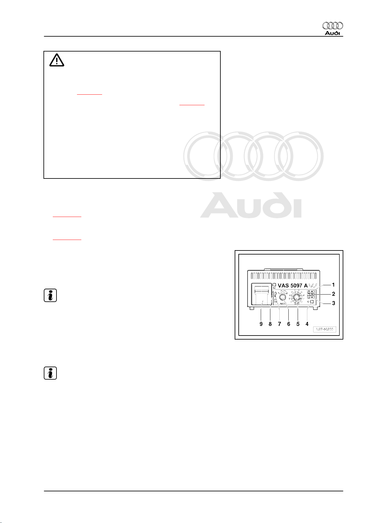
– Set the low temperature test current with the selector switch
-5-.
– Set the measuring range, 80 - 379 A or 380 - 499 A, with the
ON/OFF switch -6-.
Note
Batteries with a low temperature test current of 520 A according
to DIN can be checked with the setting for 499 A according to DIN.
– Connect red test clamp „+“ of battery tester to positive battery
terminal.
– Connect black test clamp „–“ of battery tester to negative bat‐
tery terminal.
Note
♦
Make sure the test clamps make proper contact.
♦
Please note the TPI 2012182 on the battery tester with printer
-VAS 5097 A- .
4. Checking battery - vehicles without battery monitor control unit J367 or energy management control unit J644 23
Page 30
Protected by copyright. Copying for private or commercial purposes, in part or in whole, is not
permitted unless authorised by AUDI AG. AUDI AG does not guarantee or accept any liability
with respect to the correctness of information in this document. Copyright by AUDI AG.
Audi A1 2011 ➤ , Audi A2 2001 ➤ , Audi A3 2004 ➤ , Audi A4 2001 ➤ , Au ...
Electrical system; General information - Edition 10.2010
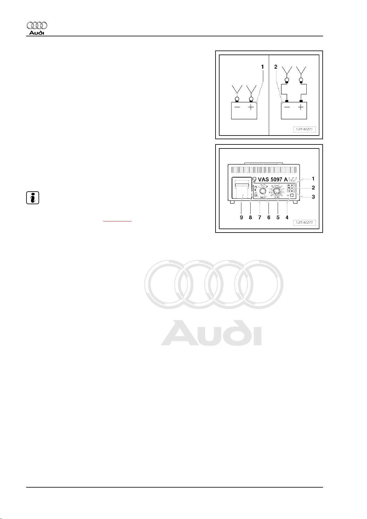
– Use the sliding switch -7- to select the connection point for the
test clamps.
1 - Direct connection to battery
2 - Connection to external test points in engine compartment
– Check whether the low temperature test current indicated on
the battery matches the value set on the battery tester.
– Press start button -4-.
• Green LED -1- lights up.
• The test program runs through automatically.
• The printer -9- will print out the test result after 20 seconds.
Note
♦
If battery tester does not start up (no LED lights, no printout),
battery must be charged ⇒ page 35 .
♦
If red LED -2- lights up, battery tester has been connected with
reverse polarity.
♦
If red LED -3- lights up, battery is not suitable for testing. Re‐
new battery.
– Switch off battery tester with ON/OFF switch -6-.
– Detach test clamps.
24 Rep. gr.27 - Starter, current supply, CCS
Page 31

Protected by copyright. Copying for private or commercial purposes, in part or in whole, is not
permitted unless authorised by AUDI AG. AUDI AG does not guarantee or accept any liability
with respect to the correctness of information in this document. Copyright by AUDI AG.
Audi A1 2011 ➤ , Audi A2 2001 ➤ , Audi A3 2004 ➤ , Audi A4 2001 ➤ , Au ...
Electrical system; General information - Edition 10.2010
Test result on printout:
1 - Measuring range set on battery tester
2 - Diagram (-arrow- indicates battery status)
3 - Test result
4 - Battery voltage during load test
5 - Vehicle data and date must be entered by mechanic
Battery tester printout Measures
Battery Very Good Battery OK
Battery Good Battery OK
Battery Sufficient Measure current draw
⇒ page 26
Battery Not Good Measure current draw
⇒ page 26
Battery Faulty Measure current draw
⇒ page 26
Cannot be tested Charge battery ⇒ page 35
and test again
Note
Observe disposal regulations if battery has to be renewed
⇒ page 4 .
4.3 Measuring no-load voltage - vehicles
without battery monitor control unit J367- or energy management control
unit -J644-
Note
By measuring no-load voltage, for example as part of the speci‐
fied care and maintenance work for vehicles not in use or in
storage, it can be determined if the battery needs re-charging ⇒
Maintenance tables .
Special tools and workshop equipment required
♦ Hand-held multimeter -V.A.G 1526E-
Procedure
Observe the following points to ensure correct measurement.
4. Checking battery - vehicles without battery monitor control unit J367 or energy management control unit J644 25
Page 32

Protected by copyright. Copying for private or commercial purposes, in part or in whole, is not
permitted unless authorised by AUDI AG. AUDI AG does not guarantee or accept any liability
with respect to the correctness of information in this document. Copyright by AUDI AG.
Audi A1 2011 ➤ , Audi A2 2001 ➤ , Audi A3 2004 ➤ , Audi A4 2001 ➤ , Au ...
Electrical system; General information - Edition 10.2010
• Battery must NOT be subjected to electrical load within the
next 2 hours prior to measurement.
• After the battery has been charged or the engine has been
running, wait for 12 hours before performing measurements.
• Battery temperature must be at least –10 °C.
After a waiting time of at least 12 hours:
– Measure voltage between battery terminal clamps.
• Specification: 12.5 V or above = battery is OK
– If battery no-load voltage is below 12.5 V, battery must be re-
charged ⇒ page 35 .
– Current draw must be measured after a charging period of
5 minutes ⇒ page 26 .
– If battery no-load voltage is 11.6 V or less, battery is totally
discharged ⇒ page 38 .
4.4 Checking battery by measuring current
draw - vehicles without battery monitor
control unit -J367- or energy manage‐
ment control unit -J644-
Checking the current draw capacity of a battery during charging
allows you to assess quickly whether a partially or totally dis‐
charged battery ⇒ page 38 can be made serviceable again by
re-charging or whether the battery has to be renewed.
Special tools and workshop equipment required
♦ Battery charger -VAS 5095A- and trigger clamp, 100A -VAS
5051B/7- or
♦ Battery charger -VAS 5900- or
26 Rep. gr.27 - Starter, current supply, CCS
Page 33

Protected by copyright. Copying for private or commercial purposes, in part or in whole, is not
permitted unless authorised by AUDI AG. AUDI AG does not guarantee or accept any liability
with respect to the correctness of information in this document. Copyright by AUDI AG.
Audi A1 2011 ➤ , Audi A2 2001 ➤ , Audi A3 2004 ➤ , Audi A4 2001 ➤ , Au ...
♦ Battery charger -VAS 5903-
♦ Battery charger -VAS 5904-
Electrical system; General information - Edition 10.2010
♦ Battery charger -VAS 5906-
Note
♦
When charging with battery charger -VAS 5095A- , the current
draw of the battery must be measured using e.g. trigger clamp,
100A -VAS 5051B/7- . Battery chargers -VAS 5900- , -VAS
5903- , -VAS 5904- and -VAS 5906- indicate the current draw
on the unit.
♦
Information on battery chargers ⇒ Operating instructions for
appropriate battery charger.
Procedure
• Battery temperature must be at least +10 °C.
• The battery charger must be capable of supplying a charging
current of at least 30 A, as is the case for example with the
battery chargers -VAS 5095A- , -VAS 5900- , -VAS 5903- , VAS 5904- and -VAS 5906- .
• Battery charger connected and switched on
4. Checking battery - vehicles without battery monitor control unit J367 or energy management control unit J644 27
Page 34

Protected by copyright. Copying for private or commercial purposes, in part or in whole, is not
permitted unless authorised by AUDI AG. AUDI AG does not guarantee or accept any liability
with respect to the correctness of information in this document. Copyright by AUDI AG.
Audi A1 2011 ➤ , Audi A2 2001 ➤ , Audi A3 2004 ➤ , Audi A4 2001 ➤ , Au ...
Electrical system; General information - Edition 10.2010
– Measure battery charging current after a charging period of 5
minutes.
• Specification: Charging current must be greater than 10 % of
rated capacity.
• Example: Charging current for a 60 Ah battery after 5 minute
charging period: greater than 6 A.
– If reading matches specification, continue with charging proc‐
ess until battery is fully charged.
– Then check battery using the battery tester:
♦ Using battery tester with printer -VAS 6161- (no waiting time)
⇒ page 17 .
♦ Using battery tester with printer -VAS 5097A- (after charging,
wait for 12 hours) ⇒ page 21 .
– If reading is below specification, renew battery ⇒ Electrical
system; Rep. gr. 27 .
Note
Observe disposal regulations if battery has to be renewed
⇒ page 4 .
28 Rep. gr.27 - Starter, current supply, CCS
Page 35

Protected by copyright. Copying for private or commercial purposes, in part or in whole, is not
permitted unless authorised by AUDI AG. AUDI AG does not guarantee or accept any liability
with respect to the correctness of information in this document. Copyright by AUDI AG.
Audi A1 2011 ➤ , Audi A2 2001 ➤ , Audi A3 2004 ➤ , Audi A4 2001 ➤ , Au ...
Electrical system; General information - Edition 10.2010
5 Checking battery - vehicles with bat‐
tery monitor control unit -J367- or en‐
ergy management control unit -J644-
♦ On some models, the electrical system is monitored by the
energy management control unit -J644- or the battery monitor
control unit -J367- in connection with the data bus diagnostic
interface -J533- (allocation ⇒ Current flow diagrams, Electrical
fault finding and Fitting locations). The battery test for these
vehicles is performed via „Guided Fault Finding“.
♦ If is not possible to check the battery in the „Guided Fault
Finding“ because of a partially or totally discharged battery,
the charge status of the battery can be assessed quickly via
„Checking battery by measuring current draw“.
♦ Do not open maintenance-free batteries; this would invalidate
the warranty.
5.1 Checking battery using vehicle diagnos‐
tic tester
Special tools and workshop equipment required
♦ Vehicle diagnostic tester
Procedure
• Battery charger must not be connected during battery test and
engine must not be running.
• Battery temperature must be at least –10 °C.
• Temperature of diagnostic system must be between +5
and 45 °C.
– Connect vehicle diagnostic tester ⇒ page 110 .
Note
If a fault message appears on the display, refer to ⇒ Operating
instructions for vehicle diagnostic tester .
– Select Guided Functions from menu.
5. Checking battery - vehicles with battery monitor control unit J367 or energy management control unit J644 29
Page 36

Protected by copyright. Copying for private or commercial purposes, in part or in whole, is not
permitted unless authorised by AUDI AG. AUDI AG does not guarantee or accept any liability
with respect to the correctness of information in this document. Copyright by AUDI AG.
Audi A1 2011 ➤ , Audi A2 2001 ➤ , Audi A3 2004 ➤ , Audi A4 2001 ➤ , Au ...
Electrical system; General information - Edition 10.2010
Display (example):
– Enter vehicle identification by touching the appropriate mes‐
sage line -1- in accordance with the selection prompt -A-.
– Select function or path:
Vehicle brand
Engine code
61 - Battery control or
19 - Data bus diagnostic interface or
Service work
A - Battery, Testing (Repair group 27)
– Continue to follow the instructions on the display of the vehicle
diagnostic tester; the following messages can be displayed:
• Battery OK.
• Re-charge battery.
• Renew battery.
After performing battery test:
– Press Go to button.
– Select „End“ function in list.
– Switch off ignition and separate diagnostic connection.
– If necessary, re-charge ⇒ page 35 or renew battery ⇒ Elec‐
trical system; Rep. gr. 27 .
Note
Observe disposal regulations if battery has to be renewed
⇒ page 4 .
5.2 Checking battery by measuring current
draw - vehicles with battery monitor con‐
trol unit -J367- or energy management
control unit -J644-
Checking the current draw capacity of a battery during charging
allows you to assess quickly whether a partially or totally dis‐
charged battery ⇒ page 38 can be made serviceable again by
re-charging or whether the battery has to be renewed.
Special tools and workshop equipment required
♦ Battery charger -VAS 5095A- and trigger clamp, 100A -VAS
5051B/7- or
30 Rep. gr.27 - Starter, current supply, CCS
Page 37

Protected by copyright. Copying for private or commercial purposes, in part or in whole, is not
permitted unless authorised by AUDI AG. AUDI AG does not guarantee or accept any liability
with respect to the correctness of information in this document. Copyright by AUDI AG.
Audi A1 2011 ➤ , Audi A2 2001 ➤ , Audi A3 2004 ➤ , Audi A4 2001 ➤ , Au ...
♦ Battery charger -VAS 5900- or
♦ Battery charger -VAS 5903-
Electrical system; General information - Edition 10.2010
♦ Battery charger -VAS 5904-
♦ Battery charger -VAS 5906-
5. Checking battery - vehicles with battery monitor control unit J367 or energy management control unit J644 31
Page 38

Protected by copyright. Copying for private or commercial purposes, in part or in whole, is not
permitted unless authorised by AUDI AG. AUDI AG does not guarantee or accept any liability
with respect to the correctness of information in this document. Copyright by AUDI AG.
Audi A1 2011 ➤ , Audi A2 2001 ➤ , Audi A3 2004 ➤ , Audi A4 2001 ➤ , Au ...
Electrical system; General information - Edition 10.2010
Note
♦
When charging with battery charger -VAS 5095A- , current
draw of battery must be measured using e.g. trigger clamp,
100A -VAS 5051B/7- . Battery chargers -VAS 5900- , -VAS
5903- , -VAS 5904- and -VAS 5906- indicate the current draw
on the unit.
♦
Information on battery chargers ⇒ Operating instructions for
appropriate battery charger.
Procedure
• Battery temperature must be at least +10 °C.
• The battery charger must be capable of supplying a charging
current of at least 30 A, as is the case for example with the
battery chargers -VAS 5095A- , -VAS 5900- , -VAS 5903- , VAS 5904- and -VAS 5906- .
• Battery charger connected and switched on
– Measure battery charging current after a charging period of 5
minutes.
• Specification: Charging current must be greater than 10 % of
rated capacity.
• Example: Charging current for a 60 Ah battery after 5 minute
charging period: greater than 6 A.
– If reading matches specification, continue with charging proc‐
ess until battery is fully charged.
– Then check battery using vehicle diagnostic tester
⇒ page 29 .
– If reading is below specification, renew battery ⇒ Electrical
system; Rep. gr. 27 .
Note
Observe disposal regulations if battery has to be renewed
⇒ page 4 .
5.3 Measuring no-load voltage - vehicles
with battery monitor control unit -J367or energy management control unit J644- „transport mode not active“
Note
No-load voltage measurement for assessment of battery condi‐
tion is only advisable if it is not possible to test the battery with a
vehicle diagnostic tester and if transport mode is not active in
battery monitor control unit -J367- or energy management control
unit -J644- .
Special tools and workshop equipment required
32 Rep. gr.27 - Starter, current supply, CCS
Page 39

Protected by copyright. Copying for private or commercial purposes, in part or in whole, is not
permitted unless authorised by AUDI AG. AUDI AG does not guarantee or accept any liability
with respect to the correctness of information in this document. Copyright by AUDI AG.
Audi A1 2011 ➤ , Audi A2 2001 ➤ , Audi A3 2004 ➤ , Audi A4 2001 ➤ , Au ...
Electrical system; General information - Edition 10.2010
♦ Hand-held multimeter -V.A.G 1526E-
Procedure
– Always observe the following; otherwise correct measurement
is not guaranteed.
• Leave battery in vehicle; do not disconnect earth cable.
• Open bonnet or rear lid and fix lock in „Locked“ position to stop
luggage compartment light coming on.
• Use central locking system to lock vehicle.
• Battery must NOT be subjected to electrical load within the
next 2 hours prior to measurement.
• Battery must NOT be charged in the 12 hours prior to meas‐
urement.
• Battery temperature must be at least –10 °C.
– Perform preparations for no-load voltage measurement ⇒
Electrical system; Rep. gr. 27 .
After a waiting time of at least 2 hours:
– Connect hand-held multimeter -V.A.G 1526E- between bat‐
tery terminal clamps or to remote positive terminal „+“ and to
remote earth terminal „–“.
– Measure voltage between battery terminal clamps.
• Specification: 12.5 V or above = battery is OK
– If battery no-load voltage is below 12.5 V, battery must be re-
charged ⇒ page 35 .
– Current draw must be measured after a charging period of
5 minutes ⇒ page 30 .
– If battery no-load voltage is 11.6 V or less, battery is totally
discharged ⇒ page 38 .
5.4 Measuring no-load voltage - vehicles
with battery monitor control unit -J367or energy management control unit J644- „transport mode active“
Note
As part of the specified care and maintenance work for vehicles
not in use or in storage, the state of charge in % (SOC) can be
read off the trip recorder with the transport mode active. This
shows whether the battery needs charging ⇒ Maintenance ta‐
bles .
5. Checking battery - vehicles with battery monitor control unit J367 or energy management control unit J644 33
Page 40

Protected by copyright. Copying for private or commercial purposes, in part or in whole, is not
permitted unless authorised by AUDI AG. AUDI AG does not guarantee or accept any liability
with respect to the correctness of information in this document. Copyright by AUDI AG.
Audi A1 2011 ➤ , Audi A2 2001 ➤ , Audi A3 2004 ➤ , Audi A4 2001 ➤ , Au ...
Electrical system; General information - Edition 10.2010
Procedure
The following test can only be performed if the transport mode is
activated in the battery monitor control unit -J367- or the energy
management control unit -J644- . If the transport mode is activa‐
ted later, for example when storing used vehicles, the SOC can
only be determined after the systems have switched to „data bus
rest mode“ once.
– Open driver's door.
– Switch on ignition.
– Read SOC in % off trip recorder.
Note
Depending on version, the value can be preceded by „TRA“.
• Specification: 50 % or above, charge state of battery is OK.
– If charge state of battery is below 50 %, battery must be charg‐
ed ⇒ page 35 .
– Current draw must be measured after a charging period of
5 minutes ⇒ page 30 .
– If charge state of battery is 0 %, battery is totally discharged
⇒ page 38 .
34 Rep. gr.27 - Starter, current supply, CCS
Page 41

Protected by copyright. Copying for private or commercial purposes, in part or in whole, is not
permitted unless authorised by AUDI AG. AUDI AG does not guarantee or accept any liability
with respect to the correctness of information in this document. Copyright by AUDI AG.
Audi A1 2011 ➤ , Audi A2 2001 ➤ , Audi A3 2004 ➤ , Audi A4 2001 ➤ , Au ...
Electrical system; General information - Edition 10.2010
6 Charging battery
6.1 Charging battery with battery charger -
VAS 5095A- , -VAS 5900- , -VAS 5903- ,
-VAS 5904- or -VAS 5906-
Special tools and workshop equipment required
♦ Battery charger -VAS 5095A- or
♦ Battery charger -VAS 5900- or
♦ Battery charger -VAS 5903-
6. Charging battery 35
Page 42

Protected by copyright. Copying for private or commercial purposes, in part or in whole, is not
permitted unless authorised by AUDI AG. AUDI AG does not guarantee or accept any liability
with respect to the correctness of information in this document. Copyright by AUDI AG.
Audi A1 2011 ➤ , Audi A2 2001 ➤ , Audi A3 2004 ➤ , Audi A4 2001 ➤ , Au ...
Electrical system; General information - Edition 10.2010
♦ Battery charger -VAS 5904-
♦ Battery charger -VAS 5906-
Note
♦
Battery chargers -VAS 5095A- , -VAS 5900- , -VAS 5903- , VAS 5904- and -VAS 5906- charge without current and volt‐
age peaks. Batteries can therefore also be charged when
installed. Safety precautions must be observed when doing
so. The chargers have a back-up function enabling them to
supply power to on-board circuits.
♦
If electrical equipment has to be switched on periodically when
performing work on the electrical system and for the „Guided
Fault Finding“ mode, the battery must be charged using a
charger with back-up function so as not to damage the battery
⇒ page 40 .
♦
Information on battery chargers ⇒ Operating instructions for
appropriate battery charger.
Procedure
• Battery temperature must be at least +10 °C.
36 Rep. gr.27 - Starter, current supply, CCS
Page 43

Protected by copyright. Copying for private or commercial purposes, in part or in whole, is not
permitted unless authorised by AUDI AG. AUDI AG does not guarantee or accept any liability
with respect to the correctness of information in this document. Copyright by AUDI AG.
Audi A1 2011 ➤ , Audi A2 2001 ➤ , Audi A3 2004 ➤ , Audi A4 2001 ➤ , Au ...
Electrical system; General information - Edition 10.2010
WARNING
Risk of explosion due to naked flames, fires and smoking.
♦ Sealing plugs of batteries which are not maintenance-free
must be firmly screwed in.
♦ Ensure good ventilation.
♦ A highly inflammable gas is given off when batteries are
charged. Smoking and naked lights are consequently not
allowed in rooms in which batteries are being charged.
♦ Observe safety regulations of manufacturers of battery
charger and battery.
♦ Rapid-charging of battery ⇒ page 39 .
Risk of explosion due to a discharged battery with „magic eye“.
♦ The battery must NOT be checked or charged if the indi‐
cator of the „magic eye“ is colourless or yellow. Do NOT
boost start the vehicle. There is a risk of explosion when
checking or charging the battery or boost starting the ve‐
hicle. The battery must be renewed.
Caution
Risk of damage to valve-regulated lead acid or AGM batteries.
♦ Valve-regulated lead acid or AGM batteries may only be
charged up to a limited voltage.
– Switch off ignition and take out ignition key.
– Switch off all electrical equipment.
– Perform preparations for charging battery ⇒ Electrical system;
Rep. gr. 27 .
Note
♦
On vehicles without battery monitor control unit -J367- or en‐
ergy management control unit -J644- , clamps of battery
charger can be connected to battery terminals or remote pos‐
itive terminal and remote earth terminal in engine compart‐
ment.
♦
On vehicles with battery monitor control unit -J367- or energy
management control unit -J644- , black clamp „–“ must not be
connected to negative battery terminal, but to remote earth
terminal in engine compartment or to earth stud of energy
management control unit -J644- .
– After connecting charging clamps, plug in mains connector of
battery charger.
– Switch on battery charger.
– If necessary, set charging current at battery charger according
to battery capacity.
• The charging current should be around 10 % of the battery
capacity (so for a 60 Ah battery around 6 A).
6. Charging battery 37
Page 44

Protected by copyright. Copying for private or commercial purposes, in part or in whole, is not
permitted unless authorised by AUDI AG. AUDI AG does not guarantee or accept any liability
with respect to the correctness of information in this document. Copyright by AUDI AG.
Audi A1 2011 ➤ , Audi A2 2001 ➤ , Audi A3 2004 ➤ , Audi A4 2001 ➤ , Au ...
Electrical system; General information - Edition 10.2010
– Once battery has been fully charged ⇒ Battery charger oper‐
ating instructions , disconnect charging clamps „+“ and „–“ of
battery charger from battery.
– Unplug mains connector of battery charger.
6.2 Totally discharged battery
♦ Batteries that have not been used for an extended period of
time, e.g. in vehicles that have been stored, self-discharge.
♦ A battery is considered to be totally discharged if the no-load
voltage has dropped below 11.6 V. Initial battery damage can
occur below 12.2 V (if vehicle has been stored for a longer
period).
♦ On vehicles without battery monitor control unit -J367- or en‐
ergy management control unit -J644- , measure no-load volt‐
age ⇒ page 25 .
♦ On vehicles with battery monitor control unit -J367- or energy
management control unit -J644- , perform battery test using
vehicle diagnostic tester ⇒ page 29 .
♦ In a totally discharged battery the electrolyte (sulphuric acid/
water mixture) is reduced to almost all water, as the sulphuric
acid content is heavily reduced.
♦ Totally discharged batteries become sulphated, i.e. the entire
battery plate surfaces harden. The electrolyte has a slightly
milky appearance (instead of being clear).
♦ If discharged batteries are charged directly after being dis‐
charged, the sulphation dissipates.
♦ If this is not done, the plates become even harder and the bat‐
tery's ability to absorb charge is impaired. This results in
reduced power output.
Procedure
• Battery temperature must be at least +10 °C.
WARNING
Risk of explosion due to a discharged battery with „magic eye“.
♦ The battery must NOT be checked or charged if the indi‐
cator of the „magic eye“ is colourless or yellow. Do NOT
boost start the vehicle. There is a risk of explosion when
checking or charging the battery or boost starting the ve‐
hicle. The battery must be renewed.
Caution
Totally discharged batteries: Danger of freezing.
♦ Totally discharged batteries may freeze even at temper‐
atures only slightly below zero, causing the housing to
burst.
♦ Never re-use frozen batteries.
Totally discharged batteries (that are also sulphated) must be
charged as follows using a low charging current:
– Set charging current to approx. 5 % of battery capacity, i.e. for
a 60 Ah battery charging current is approx. 3 A.
38 Rep. gr.27 - Starter, current supply, CCS
Page 45

Protected by copyright. Copying for private or commercial purposes, in part or in whole, is not
permitted unless authorised by AUDI AG. AUDI AG does not guarantee or accept any liability
with respect to the correctness of information in this document. Copyright by AUDI AG.
Audi A1 2011 ➤ , Audi A2 2001 ➤ , Audi A3 2004 ➤ , Audi A4 2001 ➤ , Au ...
Electrical system; General information - Edition 10.2010
Note
♦
Battery voltage must be at least 0.6 V.
♦
Battery chargers -VAS 5095A- , -VAS 5900- , -VAS 5903- , VAS 5904- and -VAS 5906- detect totally discharged batteries
automatically and start the charging process gently at a low
charging current. Charging current is adapted automatically to
battery charge.
Caution
Danger of damage to totally discharged batteries.
♦ Do NOT attempt to rapid-charge totally discharged bat‐
teries.
– Charge battery ⇒ page 35 .
• Charging voltage must not exceed 14.4 V.
Note
Observe disposal regulations if battery has to be renewed
⇒ page 4 .
6.3 Rapid-charging battery - vehicles with‐
out battery monitor control unit -J367- or
energy management control unit -J644-
Procedure
• Battery temperature must be at least +10 °C.
WARNING
Risk of explosion due to naked flames, fires and smoking.
♦ Sealing plugs of batteries which are not maintenance-free
must be firmly screwed in.
♦ Ensure good ventilation.
♦ A highly inflammable gas is given off when batteries are
charged. Smoking and naked lights are consequently not
allowed in rooms in which batteries are being charged.
♦ Observe safety regulations of manufacturers of battery
charger and battery.
Risk of explosion due to a discharged battery with „magic eye“.
♦ The battery must NOT be checked or charged if the indi‐
cator of the „magic eye“ is colourless or yellow. Do NOT
boost start the vehicle. There is a risk of explosion when
checking or charging the battery or boost starting the ve‐
hicle. The battery must be renewed.
6. Charging battery 39
Page 46

Protected by copyright. Copying for private or commercial purposes, in part or in whole, is not
permitted unless authorised by AUDI AG. AUDI AG does not guarantee or accept any liability
with respect to the correctness of information in this document. Copyright by AUDI AG.
Audi A1 2011 ➤ , Audi A2 2001 ➤ , Audi A3 2004 ➤ , Audi A4 2001 ➤ , Au ...
Electrical system; General information - Edition 10.2010
Caution
Risk of damage to battery and electronic vehicle components.
♦ Valve-regulated lead acid or AGM batteries must NOT be
rapid-charged.
♦ Do not rapid-charge batteries in vehicles with battery mon‐
itor control unit -J367- or energy management control unit
-J644- .
♦ Do NOT attempt to rapid-charge totally discharged bat‐
teries.
♦ Rapid-charging of batteries should only be performed in
exceptional circumstances (e.g. if necessary to start the
engine) as rapid-charging may cause damage.
♦ Battery must not be connected to vehicle electrical system
when performing rapid-charging. Disconnect earth cable
and positive wires ⇒ Electrical system; Rep. gr. 27 .
♦ Charging voltage must not exceed 14.8 V.
Note
Observe disposal regulations if battery has to be renewed
⇒ page 4 .
6.4 Back-up power supply of battery via bat‐
tery charger -VAS 5095A- , -VAS 5900- ,
-VAS 5903- , -VAS 5904- or -VAS 5906-
Back-up power supply of battery is required for example at the
workshop for Fault Finding or when renewing battery.
Special tools and workshop equipment required
♦ Battery charger -VAS 5095A- or
40 Rep. gr.27 - Starter, current supply, CCS
Page 47

Protected by copyright. Copying for private or commercial purposes, in part or in whole, is not
permitted unless authorised by AUDI AG. AUDI AG does not guarantee or accept any liability
with respect to the correctness of information in this document. Copyright by AUDI AG.
Audi A1 2011 ➤ , Audi A2 2001 ➤ , Audi A3 2004 ➤ , Audi A4 2001 ➤ , Au ...
♦ Battery charger -VAS 5900- or
♦ Battery charger -VAS 5903-
Electrical system; General information - Edition 10.2010
♦ Battery charger -VAS 5904-
♦ Battery charger -VAS 5906-
6. Charging battery 41
Page 48

Protected by copyright. Copying for private or commercial purposes, in part or in whole, is not
permitted unless authorised by AUDI AG. AUDI AG does not guarantee or accept any liability
with respect to the correctness of information in this document. Copyright by AUDI AG.
Audi A1 2011 ➤ , Audi A2 2001 ➤ , Audi A3 2004 ➤ , Audi A4 2001 ➤ , Au ...
Electrical system; General information - Edition 10.2010
Procedure
Note
♦
Information on battery chargers ⇒ Operating instructions for
appropriate battery charger.
♦
The following instructions describe the back-up power supply
mode with battery charger -VAS 5900- .
– Switch off ignition and take out ignition key.
– Switch off all electrical equipment.
– Plug in mains connector of battery charger -VAS 5900- .
• The display shows the last mode selected.
– Press and hold Start/Stop button for approx. 5 seconds.
• Menu option „charging totally discharged batteries/back-up
supply“ is activated.
– Press button ↑ or ↓ to select vehicle voltage.
Note
The battery charger -VAS 5900- returns to the main menu if no
button is pressed within 5 seconds.
– Press Start/Stop button to confirm selected battery voltage.
– Perform preparation for back-up power supply of battery ⇒
Electrical system; Rep. gr. 27 .
• Battery charger will check correct polarity of clamps.
Caution
Risk of damage to battery charger -VAS 5900- and electronic
vehicle components.
♦
Start/Stop
button must not be pressed if the battery ter‐
minal clamps are not connected correctly.
– Press Start/Stop button to confirm correct connection of
clamps.
• Battery charger -VAS 5900- will start back-up power supply.
– Press Start/Stop button to end back-up power supply.
– Unplug mains connector of battery charger.
6.5 Maintaining battery charge with solar panel -VAS 6102 A-
♦ The solar panel -VAS 6102 A- supports the vehicle's electrical
system and prevents self-discharge of the battery.
♦ All rechargeable batteries may be charged with the solar pan‐
el.
♦ The solar panel must be connected to the diagnostic connec‐
tion in the vehicle. Battery chargers must not be connected to
the diagnostic connection.
42 Rep. gr.27 - Starter, current supply, CCS
Page 49

Protected by copyright. Copying for private or commercial purposes, in part or in whole, is not
permitted unless authorised by AUDI AG. AUDI AG does not guarantee or accept any liability
with respect to the correctness of information in this document. Copyright by AUDI AG.
Audi A1 2011 ➤ , Audi A2 2001 ➤ , Audi A3 2004 ➤ , Audi A4 2001 ➤ , Au ...
Electrical system; General information - Edition 10.2010
Special tools and workshop equipment required
♦ Solar panel -VAS 6102 A-
Procedure
Note
For information on solar panel -VAS 6102 A- ⇒ Operating in‐
structions for -VAS 6102 A- .
– Secure solar panel -VAS 6102 A- to interior mirror -1-.
– Place underside of solar panel on dash panel -2-.
Note
Do not allow the complete solar panel -VAS 6102 A- to make
contact with the dash panel; only place down the lower edge to
provide support. Placing down the whole panel can result in col‐
our change of the dash panel.
– Pull securing cable together until solar panel is close to wind‐
screen.
– Connect solar panel -arrow- to diagnostic connection of vehi‐
cle.
• The green LED in the solar panel frame indicates the function:
the brighter this LED lights up, the higher is the charging cur‐
rent; however, the integrated electronics prevent overcharging
the battery.
6. Charging battery 43
Page 50

Protected by copyright. Copying for private or commercial purposes, in part or in whole, is not
permitted unless authorised by AUDI AG. AUDI AG does not guarantee or accept any liability
with respect to the correctness of information in this document. Copyright by AUDI AG.
Audi A1 2011 ➤ , Audi A2 2001 ➤ , Audi A3 2004 ➤ , Audi A4 2001 ➤ , Au ...
Electrical system; General information - Edition 10.2010
7 Checking and servicing alternator
7.1 Checking alternator
– The alternator is checked in „Guided Fault Finding“ function
under „Body/electrical system / 27 - Starter, current supply/
electrical components / C- Alternator, checking“ ⇒ Vehicle di‐
agnostic, testing and information system VAS 5051.
7.2 Bosch alternator up to 2000 - exploded view
1 - Bolts
❑ 1 Nm
2 - Cover
❑ With three retaining tabs
3 - Bolts
❑ 2 Nm
4 - Voltage regulator
❑ Removing:
– Unscrew bolts -item 1-
and detach protective
cap -item 2-
– Unscrew bolts -item 3-
and detach voltage reg‐
ulator
❑ Carbon brush wear limit:
5 mm
5 - Alternator
44 Rep. gr.27 - Starter, current supply, CCS
Page 51

Protected by copyright. Copying for private or commercial purposes, in part or in whole, is not
permitted unless authorised by AUDI AG. AUDI AG does not guarantee or accept any liability
with respect to the correctness of information in this document. Copyright by AUDI AG.
Audi A1 2011 ➤ , Audi A2 2001 ➤ , Audi A3 2004 ➤ , Audi A4 2001 ➤ , Au ...
Electrical system; General information - Edition 10.2010
7.3 Bosch alternator from 2001 onwards - exploded view
Note
The alternators were introduced gradually.
1 - Alternator
2 - Voltage regulator
❑ Removing and installing
⇒ page 46
❑ Checking carbon brush‐
es ⇒ page 48
3 - Bolt
❑ 2.5 Nm
4 - Cover
5 - Nut
❑ 12 Nm
6 - Nut
❑ 30 Nm
7 - Bolt
❑ 3 Nm
8 - Bolt
❑ 1.5 Nm
7. Checking and servicing alternator 45
Page 52

Protected by copyright. Copying for private or commercial purposes, in part or in whole, is not
permitted unless authorised by AUDI AG. AUDI AG does not guarantee or accept any liability
with respect to the correctness of information in this document. Copyright by AUDI AG.
Audi A1 2011 ➤ , Audi A2 2001 ➤ , Audi A3 2004 ➤ , Audi A4 2001 ➤ , Au ...
Electrical system; General information - Edition 10.2010
7.4 Removing and installing voltage regula‐
tor - Bosch alternator from 2001 on‐
wards
Removing
– Remove alternator ⇒ Electrical system; Rep. gr. 27 .
– Unscrew bolt -1- and nuts -3- and -4-.
– Detach cover -2- from rear of alternator.
– Unscrew bolts -arrows-.
– Remove voltage regulator.
Installing
– When positioning voltage regulator, ensure carbon brushes
are positioned correctly on contact surfaces.
Further installation is carried out in the reverse order; note the
following:
– Install alternator ⇒ Electrical system; Rep. gr. 27 .
• Tightening torque ⇒ page 45
46 Rep. gr.27 - Starter, current supply, CCS
Page 53

Protected by copyright. Copying for private or commercial purposes, in part or in whole, is not
permitted unless authorised by AUDI AG. AUDI AG does not guarantee or accept any liability
with respect to the correctness of information in this document. Copyright by AUDI AG.
Audi A1 2011 ➤ , Audi A2 2001 ➤ , Audi A3 2004 ➤ , Audi A4 2001 ➤ , Au ...
Electrical system; General information - Edition 10.2010
7.5 Bosch alternator from 2007 onwards - exploded view
Note
The new alternators were introduced gradually.
1 - Nut
❑ 65 Nm
2 - Poly V-belt pulley
3 - Alternator
4 - Voltage regulator
❑ Removing and installing
⇒ page 48
❑ Checking carbon brush‐
es ⇒ page 48
5 - Bolt
❑ 1.5 Nm
6 - Cover
7 - Bolt
❑ 3 Nm
8 - Bolt
❑ 2.5 Nm
7. Checking and servicing alternator 47
Page 54

Protected by copyright. Copying for private or commercial purposes, in part or in whole, is not
permitted unless authorised by AUDI AG. AUDI AG does not guarantee or accept any liability
with respect to the correctness of information in this document. Copyright by AUDI AG.
Audi A1 2011 ➤ , Audi A2 2001 ➤ , Audi A3 2004 ➤ , Audi A4 2001 ➤ , Au ...
Electrical system; General information - Edition 10.2010
7.6 Removing and installing voltage regula‐
tor - Bosch alternator from 2007 on‐
wards
Removing
– Remove alternator ⇒ Electrical system; Rep. gr. 27 .
– Unscrew bolts -arrows-.
– Detach cover -1- from rear of alternator.
– Unscrew bolts -arrows-.
– Detach voltage regulator -1-.
Installing
– When positioning voltage regulator, ensure carbon brushes
are positioned correctly on contact surfaces.
Further installation is carried out in the reverse order; note the
following:
– Install alternator ⇒ Electrical system; Rep. gr. 27 .
• Tightening torque ⇒ page 45
7.7 Checking carbon brushes - all types of Bosch alternators from 2001 onwards
Procedure
– Remove voltage regulator: Up to 2007 ⇒ page 46 ; from 2007
onwards ⇒ page 48 .
– Check length -a- of carbon brushes.
• Wear limit: -a- = 5 mm.
– Install voltage regulator: Up to 2007 ⇒ page 46 ; from 2007
onwards ⇒ page 48 .
48 Rep. gr.27 - Starter, current supply, CCS
Page 55

Protected by copyright. Copying for private or commercial purposes, in part or in whole, is not
permitted unless authorised by AUDI AG. AUDI AG does not guarantee or accept any liability
with respect to the correctness of information in this document. Copyright by AUDI AG.
Audi A1 2011 ➤ , Audi A2 2001 ➤ , Audi A3 2004 ➤ , Audi A4 2001 ➤ , Au ...
Electrical system; General information - Edition 10.2010
7.8 Valeo alternator up to 2000 - exploded view
1 - Alternator
2 - Voltage regulator
❑ Removing:
– Remove nuts -item 5-
and detach cover
-item 4-
– Unscrew bolt -item 6-
and nuts -item 7- and
detach voltage regulator
❑ Carbon brush wear limit:
5 mm
3 - Protective cap
4 - Cover
5 - Nut
❑ 2 Nm
6 - Bolt
❑ 2 Nm
7 - Nut
❑ 2x
❑ 3.5 Nm
7. Checking and servicing alternator 49
Page 56

Protected by copyright. Copying for private or commercial purposes, in part or in whole, is not
permitted unless authorised by AUDI AG. AUDI AG does not guarantee or accept any liability
with respect to the correctness of information in this document. Copyright by AUDI AG.
Audi A1 2011 ➤ , Audi A2 2001 ➤ , Audi A3 2004 ➤ , Audi A4 2001 ➤ , Au ...
Electrical system; General information - Edition 10.2010
7.9 Valeo alternator from 2001 onwards - exploded view
Note
The alternators were introduced gradually.
1 - Alternator
2 - Voltage regulator
❑ Removing and instal‐
ling: Up to 2007
⇒ page 51 ; from 2007
onwards ⇒ page 52
❑ Checking carbon brush‐
es: Up to 2007
⇒ page 51 ; from 2007
onwards ⇒ page 52
3 - Bolt
❑ 2 Nm
4 - Cover
5 - Protective cap
6 - Bolt
❑ 2 Nm
50 Rep. gr.27 - Starter, current supply, CCS
Page 57

Protected by copyright. Copying for private or commercial purposes, in part or in whole, is not
permitted unless authorised by AUDI AG. AUDI AG does not guarantee or accept any liability
with respect to the correctness of information in this document. Copyright by AUDI AG.
Audi A1 2011 ➤ , Audi A2 2001 ➤ , Audi A3 2004 ➤ , Audi A4 2001 ➤ , Au ...
Electrical system; General information - Edition 10.2010
7.10 Removing and installing voltage regula‐
tor - Valeo alternator from 2001 onwards
Removing
– Remove alternator ⇒ Electrical system; Rep. gr. 27 .
– Press cover on rear of alternator off studs -arrows-.
– Unscrew bolts -1- and centre hex stud -2-.
– Remove voltage regulator.
Installing
– Press protective cap -2- off voltage regulator -1- in direction of
-arrow-.
– When positioning voltage regulator, ensure carbon brushes
are positioned correctly on contact surfaces.
– Refit protective cap when voltage regulator has been installed.
Further installation is carried out in the reverse order; note the
following:
– Install alternator ⇒ Electrical system; Rep. gr. 27 .
• Tightening torque ⇒ page 50
7.11 Checking carbon brushes - Valeo alter‐
nator from 2001 onwards
Procedure
– Remove voltage regulator ⇒ page 51 .
– Check length -a- of carbon brushes.
• Wear limit: -a- = 5 mm.
– Install voltage regulator ⇒ page 51 .
7. Checking and servicing alternator 51
Page 58

Protected by copyright. Copying for private or commercial purposes, in part or in whole, is not
permitted unless authorised by AUDI AG. AUDI AG does not guarantee or accept any liability
with respect to the correctness of information in this document. Copyright by AUDI AG.
Audi A1 2011 ➤ , Audi A2 2001 ➤ , Audi A3 2004 ➤ , Audi A4 2001 ➤ , Au ...
Electrical system; General information - Edition 10.2010
7.12 Removing and installing voltage regula‐
tor - Valeo alternator from 2007 onwards
Special tools and workshop equipment required
♦ Feeler gauge, 0.3 mm
Removing
– Remove alternator ⇒ Electrical system; Rep. gr. 27 .
– Press cover on rear of alternator off studs -arrows-.
– Unscrew bolts -1- and centre hex stud -2-.
– Remove voltage regulator.
Installing
– Insert 0.3 mm feeler gauge -item 4- between protective cap
-2- and carbon brushes -3-.
– Pull protective cap off only as far as point where projection on
protective cap keeps carbon brushes pressed down.
– After installing voltage regulator, press protective cap on as
far as stop.
Further installation is carried out in the reverse order; note the
following:
– Install alternator ⇒ Electrical system; Rep. gr. 27 .
• Tightening torque ⇒ page 50
7.13 Checking carbon brushes - Valeo alter‐
nator from 2007 onwards
Special tools and workshop equipment required
♦ Feeler gauge, 0.3 mm
52 Rep. gr.27 - Starter, current supply, CCS
Page 59

Protected by copyright. Copying for private or commercial purposes, in part or in whole, is not
permitted unless authorised by AUDI AG. AUDI AG does not guarantee or accept any liability
with respect to the correctness of information in this document. Copyright by AUDI AG.
Audi A1 2011 ➤ , Audi A2 2001 ➤ , Audi A3 2004 ➤ , Audi A4 2001 ➤ , Au ...
Electrical system; General information - Edition 10.2010
Procedure
– Remove voltage regulator ⇒ page 52 .
– Insert 0.3 mm feeler gauge -item 3- between protective cap
-2- and carbon brushes.
– Pull protective cover off voltage regulator -1- -arrow-.
– Check length -a- of carbon brushes.
• Wear limit: -a- = 5 mm.
– With protective cap -2- in position, press down carbon brushes
-3- with feeler gauge -4-.
– Slide protective cap on in direction of -arrow- until projection
on protective cap keeps carbon brushes pressed down.
– Install voltage regulator ⇒ page 52 .
7.14 Removing and installing poly V-belt pul‐
ley without free-wheel
Special tools and workshop equipment required
7. Checking and servicing alternator 53
Page 60

Protected by copyright. Copying for private or commercial purposes, in part or in whole, is not
permitted unless authorised by AUDI AG. AUDI AG does not guarantee or accept any liability
with respect to the correctness of information in this document. Copyright by AUDI AG.
Audi A1 2011 ➤ , Audi A2 2001 ➤ , Audi A3 2004 ➤ , Audi A4 2001 ➤ , Au ...
Electrical system; General information - Edition 10.2010
♦ Socket -3310-
♦ 8 mm hexagon socket or TORX T50 socket
Removing
– Remove alternator ⇒ Electrical system; Rep. gr. 27 .
– If fitted, press off protective cap on alternator pulley.
– Counterhold on securing nut using socket -3310- and turn al‐
ternator shaft clockwise to loosen.
– Detach poly V-belt pulley.
Installing
Installation is carried out in the reverse order; note the following:
– Turn alternator shaft anti-clockwise to tighten.
– Clip protective cap onto alternator pulley.
Tightening torque
Component Nm
Poly V-belt pulley to alternator 65
7.15 Removing and installing poly V-belt pul‐
ley with free-wheel
Special tools and workshop equipment required
♦ Adapter -3400-
♦ 8 mm hexagon socket or TORX T50 socket
54 Rep. gr.27 - Starter, current supply, CCS
Page 61

Protected by copyright. Copying for private or commercial purposes, in part or in whole, is not
permitted unless authorised by AUDI AG. AUDI AG does not guarantee or accept any liability
with respect to the correctness of information in this document. Copyright by AUDI AG.
Audi A1 2011 ➤ , Audi A2 2001 ➤ , Audi A3 2004 ➤ , Audi A4 2001 ➤ , Au ...
Electrical system; General information - Edition 10.2010
Removing
– Remove alternator ⇒ Electrical system; Rep. gr. 27 .
– If fitted, press off protective cap on alternator pulley.
– Counterhold on belt pulley using adapter -3400- and turn al‐
ternator shaft clockwise to loosen.
Installing
Installation is carried out in the reverse order; note the following:
– Turn alternator shaft anti-clockwise to tighten.
– Clip protective cap onto alternator pulley.
Tightening torque
Component Nm
Poly V-belt pulley with free-wheel to alternator 80
7. Checking and servicing alternator 55
Page 62

Protected by copyright. Copying for private or commercial purposes, in part or in whole, is not
permitted unless authorised by AUDI AG. AUDI AG does not guarantee or accept any liability
with respect to the correctness of information in this document. Copyright by AUDI AG.
Audi A1 2011 ➤ , Audi A2 2001 ➤ , Audi A3 2004 ➤ , Audi A4 2001 ➤ , Au ...
Electrical system; General information - Edition 10.2010
8 Cruise control system - vehicles with
electronic throttle
♦ On vehicles with electronic throttle, the cruise control system
functions are controlled by the engine control unit.
♦ Faults in the cruise control system are output via the engine
control unit.
– Use a vehicle diagnostic tester in „Guided Fault Finding“ mode
to identify faults.
56 Rep. gr.27 - Starter, current supply, CCS
Page 63

Protected by copyright. Copying for private or commercial purposes, in part or in whole, is not
permitted unless authorised by AUDI AG. AUDI AG does not guarantee or accept any liability
with respect to the correctness of information in this document. Copyright by AUDI AG.
Audi A1 2011 ➤ , Audi A2 2001 ➤ , Audi A3 2004 ➤ , Audi A4 2001 ➤ , Au ...
Electrical system; General information - Edition 10.2010
92 – Windscreen wash/wipe system
1 Washer fluid hoses
1.1 Disconnecting and connecting washer fluid hose connectors
Different types of hose couplings are used to connect hoses to
washer fluid pumps and washer jets or as disconnection points.
Non-secured hose coupling
– Pull the two coupling elements apart to separate connection.
– To connect, press the two coupling elements firmly together
until they engage audibly and palpably.
Secured hose coupling with retaining ring
– To separate connection, turn retaining ring -1- 90° -arrow- and
detach hose connection.
– To connect, push on hose connection and turn retaining ring
-1- -arrow- until it engages.
Secured hose coupling with retaining clip version 1
– To separate connection, lift retaining clip -1- by approx. 1 mm
-arrow- and detach hose connection.
– To connect, push on hose connection and press in retaining
clip until it engages.
1. Washer fluid hoses 57
Page 64

Protected by copyright. Copying for private or commercial purposes, in part or in whole, is not
permitted unless authorised by AUDI AG. AUDI AG does not guarantee or accept any liability
with respect to the correctness of information in this document. Copyright by AUDI AG.
Audi A1 2011 ➤ , Audi A2 2001 ➤ , Audi A3 2004 ➤ , Audi A4 2001 ➤ , Au ...
Electrical system; General information - Edition 10.2010
Secured hose coupling with retaining clip version 2
– To separate connection, lift retaining clip -1- -arrow- and de‐
tach hose connection.
– To connect, push on hose connection and press in retaining
clip until it engages.
Hose coupling for headlight washer system with retaining clip
– To separate connection, press retaining clip -1- -arrow- and
detach hose connection.
– To connect, press and hold retaining clip -arrow- and push on
hose connection.
– Check whether connection is properly engaged by pulling on
hose without pressing retaining clip.
Hose coupling for headlight washer system with O-type clip
– To separate connection, use side-cutting pliers to sever O-
type clip -1- and detach hose connection.
– To connect, slip a new O-type clip onto hose, attach hose
connection and secure O-type clip using hose clip pliers V.A.G 1275- .
Hose coupling for headlight washer system with spring clip
– To separate connection, open spring clip -1- using hose clip
pliers -V.A.G 1921- and detach hose connection.
– To connect, open spring clip using hose clip pliers -V.A.G
1921- and attach hose connection.
1.2 Servicing a smooth washer fluid pipe
Note
Smooth pipes with a diameter of 5x1 mm or 6x1 mm can be serv‐
iced using an EPDM hose (Ethylene Propylene Diene Monomer)
⇒ Electronic parts catalogue .
58 Rep. gr.92 - Windscreen wash/wipe system
Page 65

Protected by copyright. Copying for private or commercial purposes, in part or in whole, is not
permitted unless authorised by AUDI AG. AUDI AG does not guarantee or accept any liability
with respect to the correctness of information in this document. Copyright by AUDI AG.
Audi A1 2011 ➤ , Audi A2 2001 ➤ , Audi A3 2004 ➤ , Audi A4 2001 ➤ , Au ...
Electrical system; General information - Edition 10.2010
– Cut the damaged section out of the smooth pipe to be repaired,
making the cuts at right-angles to the pipe.
– Choose an appropriate EPDM hose -2- and cable tie ⇒ Elec‐
tronic parts catalogue .
– Cut the EPDM hose -2- to length such that the ends of the
smooth pipe -1- and -3- can both be slipped roughly 10 mm
into the EPDM hose -2-.
– Secure the repair joint with cable ties -1-.
– Check operation and test for leaks.
1.3 Servicing a washer fluid hose with cor‐
rugated tube
Note
Corrugated tubes can be serviced using a shrink hose ⇒ Elec‐
tronic parts catalogue .
Special tools and workshop equipment required
♦ Hot air blower -VAS 1978/14A- from wiring harness repair set
-VAS 1978 B-
1. Washer fluid hoses 59
Page 66

Protected by copyright. Copying for private or commercial purposes, in part or in whole, is not
permitted unless authorised by AUDI AG. AUDI AG does not guarantee or accept any liability
with respect to the correctness of information in this document. Copyright by AUDI AG.
Audi A1 2011 ➤ , Audi A2 2001 ➤ , Audi A3 2004 ➤ , Audi A4 2001 ➤ , Au ...
Electrical system; General information - Edition 10.2010
♦ Cutting pliers -VAS 6228-
♦ Connection piece -1J0 955 875 R-
♦ Connection piece -1J0 955 875-
Procedure
– Cut washer fluid hose at point of damage using cutting pliers
-VAS 6228- .
– Join the severed ends -1 and 4- of the washer fluid hose using
connection pieces -2 and 3-.
– Push shrink hose -5- over one end of washer fluid hose and
fit connection pieces together.
– Push shrink hose over connection pieces on washer fluid
hose.
– After pushing on the shrink hose, shrink-fit it using hot air
blower -VAS 1978/14A- .
• The shrink hose must be heated starting from the centre and
working outwards until it is sealed tight.
• Set hot air blower to appropriate temperature as indicated in
operating instructions.
• When shrink-fitting, ensure no other wires, plastic components
or insulating materials are damaged by the hot nozzle.
– Check operation and test for leaks.
60 Rep. gr.92 - Windscreen wash/wipe system
Page 67

Protected by copyright. Copying for private or commercial purposes, in part or in whole, is not
permitted unless authorised by AUDI AG. AUDI AG does not guarantee or accept any liability
with respect to the correctness of information in this document. Copyright by AUDI AG.
Audi A1 2011 ➤ , Audi A2 2001 ➤ , Audi A3 2004 ➤ , Audi A4 2001 ➤ , Au ...
Electrical system; General information - Edition 10.2010
94 – Lights, bulbs, switches - exterior
1 Safety precautions when handling
gas discharge bulbs
Never renew bulbs if you are not familiar with the necessary pro‐
cedure, safety precautions and tools required.
WARNING
High voltage! Danger to life!
♦ Always disconnect the battery earth cable before working
on parts of the gas discharge headlights marked with yel‐
low high-voltage warning symbols.
♦ Then switch dipped beam on and off again to dissipate any
remaining voltage.
♦ Switch off ignition and all electrical equipment and remove
ignition key.
♦ Never operate the gas discharge bulb control unit without
a gas discharge bulb.
♦ The gas discharge bulb may only be operated in the head‐
light housing because of the high voltages (above
28,000 V when the gas discharge bulb is ignited).
WARNING
Risk of injury from burns, UV radiation, dazzling and explosion.
♦ The gas discharge bulb may only be operated in the head‐
light housing because of the high temperatures, the ab‐
sorption of UV radiation and to avoid dazzling.
♦ Never look into the light beam as this could disturb the eye
sight for an extended period of time.
♦ Gas discharge bulbs are pressurised and can burst when
they are renewed.
♦ Always wear safety goggles and gloves when removing
and installing gas discharge bulbs.
WARNING
Observe environmental requirements.
♦ Gas discharge bulbs are hazardous waste. They contain
metallic mercury (Hg) and traces of thallium.
♦ Never break off gas discharge bulbs and do not touch
broken glass part of bulb.
♦ Observe disposal regulations. Gas discharge bulbs
should only be disposed of in the appropriate containers
at an official collection point.
1. Safety precautions when handling gas discharge bulbs 61
Page 68

Protected by copyright. Copying for private or commercial purposes, in part or in whole, is not
permitted unless authorised by AUDI AG. AUDI AG does not guarantee or accept any liability
with respect to the correctness of information in this document. Copyright by AUDI AG.
Audi A1 2011 ➤ , Audi A2 2001 ➤ , Audi A3 2004 ➤ , Audi A4 2001 ➤ , Au ...
Electrical system; General information - Edition 10.2010
Caution
♦ Do not touch the glass part of the gas discharge bulb with
bare hands. The remaining fingerprint would be evapora‐
ted by the heat of the bulb when it is switched on, become
deposited on the reflector and thus impair the brightness
of the headlight. Wear clean fabric gloves when fitting the
gas discharge bulb.
♦ Only replace defective gas discharge bulbs with gas dis‐
charge bulbs of the same type. The type can be found on
the base of the bulb or on the glass part of the bulb.
♦ When installing, make sure connectors engage properly
and are securely attached.
62 Rep. gr.94 - Lights, bulbs, switches - exterior
Page 69

Protected by copyright. Copying for private or commercial purposes, in part or in whole, is not
permitted unless authorised by AUDI AG. AUDI AG does not guarantee or accept any liability
with respect to the correctness of information in this document. Copyright by AUDI AG.
Audi A1 2011 ➤ , Audi A2 2001 ➤ , Audi A3 2004 ➤ , Audi A4 2001 ➤ , Au ...
Electrical system; General information - Edition 10.2010
96 – Lights, bulbs, switches - interior
1 Immobilizer for vehicles without entry
and start authorisation switch -E415(mechanical ignition lock)
1.1 General notes
The immobilizer control unit is integrated into the instrument clus‐
ter, i.e. the immobilizer control unit can only be renewed together
with instrument cluster ⇒ Electrical system; Rep. gr. 90 .
– If the control unit is renewed, select „Replacement“ for the ap‐
propriate control unit in the „Guided Functions“ mode ⇒ Vehi‐
cle diagnostic, testing and information system VAS 5051.
1.2 Defective transponder or loss of key
♦ The transponder is integrated into the ignition key and cannot
be renewed separately.
♦ The complete ignition key must be replaced if the transponder
is defective.
– Order a new replacement key with vehicle-specific lock num‐
ber from your importer (or distribution centre), quoting vehicle
identification number.
– Match all ignition keys in the „Guided Functions“ mode ⇒ Ve‐
hicle diagnostic, testing and information system VAS 5051.
1.3 Renewing reader coil
♦ The reader coil is integrated into the lock cylinder and cannot
be renewed separately.
♦ The complete lock cylinder must be renewed if the reader coil
is defective.
– Order a new lock cylinder with vehicle-specific lock number
from your importer (or distribution centre), quoting vehicle
identification number.
1.4 Procedure for renewing lock set
The ignition keys can only be matched in the „Guided Functions“
mode ⇒ Vehicle diagnostic, testing and information system
VAS 5051.
1. Immobilizer for vehicles without entry and start authorisation switch E415 (mechanical ignition lock) 63
Page 70

Protected by copyright. Copying for private or commercial purposes, in part or in whole, is not
permitted unless authorised by AUDI AG. AUDI AG does not guarantee or accept any liability
with respect to the correctness of information in this document. Copyright by AUDI AG.
Audi A1 2011 ➤ , Audi A2 2001 ➤ , Audi A3 2004 ➤ , Audi A4 2001 ➤ , Au ...
Electrical system; General information - Edition 10.2010
2 Immobilizer for vehicles with entry
and start authorisation switch -E415(electronic ignition lock)
The immobilizer control system is either located in the conven‐
ience system central control unit -J393- or in the entry and start
authorisation control unit -J518- . Fitting location: ⇒ Current flow
diagrams, Electrical fault finding and Fitting locations.
The following components also form part of the immobilizer:
♦ Ignition key with built-in transponder.
♦ Reader coil in entry and start authorisation switch -E415-
(electronic ignition lock).
♦ Engine control unit.
♦ Gearbox control unit.
When renewing control unit, select appropriate control unit in
„Guided Functions“ ⇒ Vehicle diagnostic, testing and information
system VAS 5051.
64 Rep. gr.96 - Lights, bulbs, switches - interior
Page 71

Protected by copyright. Copying for private or commercial purposes, in part or in whole, is not
permitted unless authorised by AUDI AG. AUDI AG does not guarantee or accept any liability
with respect to the correctness of information in this document. Copyright by AUDI AG.
Audi A1 2011 ➤ , Audi A2 2001 ➤ , Audi A3 2004 ➤ , Audi A4 2001 ➤ , Au ...
Electrical system; General information - Edition 10.2010
3 Heated steering wheel
– For fault finding, remove airbag unit ⇒ Rep. gr. 69 .
– Remove steering wheel ⇒ Rep. gr. 48 .
– Check wiring ⇒ Current flow diagrams, Electrical fault finding
and Fitting locations.
Note
The steering wheel must be renewed if the heated steering wheel
is defective.
3. Heated steering wheel 65
Page 72

Protected by copyright. Copying for private or commercial purposes, in part or in whole, is not
permitted unless authorised by AUDI AG. AUDI AG does not guarantee or accept any liability
with respect to the correctness of information in this document. Copyright by AUDI AG.
Audi A1 2011 ➤ , Audi A2 2001 ➤ , Audi A3 2004 ➤ , Audi A4 2001 ➤ , Au ...
Electrical system; General information - Edition 10.2010
4 Towing bracket
4.1 Removing and installing socket for tow‐
ing bracket - version 1
Removing
– Switch off ignition and take out ignition key.
– Unscrew bolts -arrows-.
– Detach socket from retaining plate.
Socket with rear fog light cut-out contact switch -F216- :
– Unplug connector -2- for rear fog light cut-out contact switch -
F216- and press connector -1- out of trailer socket -U10- .
Socket without rear fog light cut-out contact switch -F216- :
– Press multi-pin connector -1- out of socket -2- in direction of
-arrow-.
Version 1:
– Release retaining tabs -arrows- and then release the clips
-1- and -3 ... 5-.
– Remove frame from connectors -2-.
66 Rep. gr.96 - Lights, bulbs, switches - interior
Page 73

Protected by copyright. Copying for private or commercial purposes, in part or in whole, is not
permitted unless authorised by AUDI AG. AUDI AG does not guarantee or accept any liability
with respect to the correctness of information in this document. Copyright by AUDI AG.
Audi A1 2011 ➤ , Audi A2 2001 ➤ , Audi A3 2004 ➤ , Audi A4 2001 ➤ , Au ...
Electrical system; General information - Edition 10.2010
Version 2:
– Release retaining tabs -arrows- and then release clips
-1, 2, 3, 4, 6, 7-.
– Remove frame from multi-pin connector -5-.
Installing
Installation is carried out in the reverse order; note the following:
Note
Make sure that seals -1- and -3- are not damaged.
– Insert connectors -4- into frame -2- until they audibly engage.
4.2 Removing and installing socket for tow‐
ing bracket - version 2
Removing
Refit cable ties at the same locations when reinstalling.
– Switch off ignition and take out ignition key.
– Open out towing bracket and engage.
– Cut open cable tie -1- and remove bolts -2- and -4-.
– Press socket out of towing bracket -3- in direction of -arrow-.
Note
4. Towing bracket 67
Page 74

Protected by copyright. Copying for private or commercial purposes, in part or in whole, is not
permitted unless authorised by AUDI AG. AUDI AG does not guarantee or accept any liability
with respect to the correctness of information in this document. Copyright by AUDI AG.
Audi A1 2011 ➤ , Audi A2 2001 ➤ , Audi A3 2004 ➤ , Audi A4 2001 ➤ , Au ...
Electrical system; General information - Edition 10.2010
– Turn cover cap -1- anti-clockwise -arrow- and detach from
socket -3-.
– Detach rubber cover -2-.
– Release clips -arrows- and press multi-pin connector -2- out
of socket -1-.
– Release clips -arrows- and detach frame -1- from multi-pin
connector -3-.
Note
Pull frame off carefully so that contacts -2- of multi-pin connector
are not separated from wiring harness.
68 Rep. gr.96 - Lights, bulbs, switches - interior
Page 75

Protected by copyright. Copying for private or commercial purposes, in part or in whole, is not
permitted unless authorised by AUDI AG. AUDI AG does not guarantee or accept any liability
with respect to the correctness of information in this document. Copyright by AUDI AG.
Audi A1 2011 ➤ , Audi A2 2001 ➤ , Audi A3 2004 ➤ , Audi A4 2001 ➤ , Au ...
Electrical system; General information - Edition 10.2010
Installing
Installation is carried out in the reverse order; note the following:
– Frame -1- can only be fitted onto multi-pin connector -3- in one
position.
• Guide pins -4- can be inserted in frame in one position only
(the contacts -2- must be in the frame).
– Slide frame into multi-pin connector until it engages audibly.
4.3 Removing and installing socket for tow‐
ing bracket - version 3
Removing
– Open out towing bracket with electric control and engage in
position ⇒ Owner's Manual for the specific vehicle.
– Switch off ignition and remove ignition key.
– Remove bolts -arrows-.
– Detach socket from retaining plate.
– Detach rubber cover from socket.
– Release retaining clips -arrows- and press multi-pin connector
-2- out of socket -1-.
4. Towing bracket 69
Page 76

Protected by copyright. Copying for private or commercial purposes, in part or in whole, is not
permitted unless authorised by AUDI AG. AUDI AG does not guarantee or accept any liability
with respect to the correctness of information in this document. Copyright by AUDI AG.
Audi A1 2011 ➤ , Audi A2 2001 ➤ , Audi A3 2004 ➤ , Audi A4 2001 ➤ , Au ...
Electrical system; General information - Edition 10.2010
– Release clips -arrows- and detach frame -2- from multi-pin
connector -3-.
Note
Pull frame off carefully so that contacts -2- of multi-pin connector
are not separated from wiring harness.
Installing
Installation is carried out in the reverse order; note the following:
– Frame -1- can only be fitted onto multi-pin connector -3- in one
position.
• Guide pins -4- can be inserted in frame in one position only
(the contacts -2- must be in the frame).
– Slide frame into multi-pin connector until it engages audibly.
70 Rep. gr.96 - Lights, bulbs, switches - interior
Page 77

Protected by copyright. Copying for private or commercial purposes, in part or in whole, is not
permitted unless authorised by AUDI AG. AUDI AG does not guarantee or accept any liability
with respect to the correctness of information in this document. Copyright by AUDI AG.
Audi A1 2011 ➤ , Audi A2 2001 ➤ , Audi A3 2004 ➤ , Audi A4 2001 ➤ , Au ...
Electrical system; General information - Edition 10.2010
4.4 Pin assignment at socket for towing bracket
Socket for towing bracket, 13-pin (country-specific version)
1 - Terminal BL - turn signal (left-side)
2 - Terminal NSL - rear fog light
3 - Terminal 31 - earth
4 - Terminal BR - turn signal (right-side)
5 - Terminal 58 R - tail light (right-side)
6 - Terminal 54 - brake light
7 - Terminal 58 L - tail light (left-side)
8 - Terminal RF - reversing light
9 - ⇒ Current flow diagrams, Electrical fault finding and Fitting
locations
10 - ⇒ Current flow diagrams, Electrical fault finding and Fitting
locations
11 - ⇒ Current flow diagrams, Electrical fault finding and Fitting
locations
12 - ⇒ Current flow diagrams, Electrical fault finding and Fitting
locations
13 - ⇒ Current flow diagrams, Electrical fault finding and Fitting
locations
Socket with rear fog light cut-out contact switch -F216- :
Pin assignment at rear fog light cut-out contact switch -F216⇒ Current flow diagrams, Electrical fault finding and Fitting loca‐
tions
4. Towing bracket 71
Page 78

Protected by copyright. Copying for private or commercial purposes, in part or in whole, is not
permitted unless authorised by AUDI AG. AUDI AG does not guarantee or accept any liability
with respect to the correctness of information in this document. Copyright by AUDI AG.
Audi A1 2011 ➤ , Audi A2 2001 ➤ , Audi A3 2004 ➤ , Audi A4 2001 ➤ , Au ...
Electrical system; General information - Edition 10.2010
97 – Wiring
1 Repairing wiring harnesses and elec‐
trical connectors
Special tools and workshop equipment required
♦ Wiring harness repair set -VAS 1978 B-
Caution
♦ Wiring harness and connector repairs are only to be per‐
formed using wiring harness repair set -VAS 1978 B- .
♦ Pay attention to the relevant regulations in the individual
countries.
Note
♦
Information on how to use the wiring harness repair set -VAS
1978 B- is given in the enclosed instructions.
♦
Examples are also given showing how to repair open circuits
in wiring and defective connectors.
1.1 General information on repairs to the ve‐
hicle electrical system
WARNING
Risk of injury.
♦ Pay attention to stickers on vehicle pointing out compo‐
nents with high voltage. Remaining voltage must be dis‐
sipated before commencing repair work.
♦ Certain tools are equipped with a guard. This is placed
over the end of the tool after use to prevent injury to em‐
ployees and to protect the tip of the tool against damage.
72 Rep. gr.97 - Wiring
Page 79

Protected by copyright. Copying for private or commercial purposes, in part or in whole, is not
permitted unless authorised by AUDI AG. AUDI AG does not guarantee or accept any liability
with respect to the correctness of information in this document. Copyright by AUDI AG.
Audi A1 2011 ➤ , Audi A2 2001 ➤ , Audi A3 2004 ➤ , Audi A4 2001 ➤ , Au ...
Electrical system; General information - Edition 10.2010
Caution
♦ Pay attention to the relevant regulations in the individual
countries.
♦ Disconnecting the battery earth cable prevents accidents
when working on the vehicle electrical system. Switch off
ignition before disconnecting earth wire at battery ⇒ Elec‐
trical system; Rep. gr. 27 .
♦ Before commencing repair work, always eliminate cause
of damage, e.g. sharp body edges, defective electrical
components, corrosion etc.
Note
♦
Do not loosen earth straps on body if this can be avoided
(danger of corrosion).
♦
Further information, for example about removal and installa‐
tion of individual components, can be found in the appropriate
Workshop Manual.
1.2 ESD (electrostatic discharge) workplace
-VAS 6613-
♦ The ESD (electrostatic discharge) workplace -VAS 6613- is
designed for preventing damage to electronic components
due to static discharge.
♦ Therefore it is possible to perform repairs on extremely sen‐
sitive electronic components and open printed circuit boards.
♦ Details on repairs which must be performed on the ESD (elec‐
trostatic discharge) workplace -VAS 6613- can be found in the
relevant chapter of the appropriate Workshop Manual "Elec‐
trical system".
– For setting up the ESD (electrostatic discharge) workplace,
place the ESD table mat -3- from -VAS 6613- on a dry and
clean table.
– Connect earthing module -2- to one of the snap fasteners on
ESD table mat.
– Then proceed by plugging in connector adapter -1- of earthing
module with adapting connector to an electrical mains socket
equipped with earthing contact or attach crocodile clip to build‐
ing earth strap or water pipe.
– Connect wrist strap -4- to one of the snap fasteners on mat.
– Put on wrist strap directly on wrist – never on sleeve of shirt or
jacket.
Caution
For repairs on extremely sensitive electronic components and
open printed circuit boards always use nonmagnetic tools, e.g.
socket wrench -T10072- .
1. Repairing wiring harnesses and electrical connectors 73
Page 80

Protected by copyright. Copying for private or commercial purposes, in part or in whole, is not
permitted unless authorised by AUDI AG. AUDI AG does not guarantee or accept any liability
with respect to the correctness of information in this document. Copyright by AUDI AG.
Audi A1 2011 ➤ , Audi A2 2001 ➤ , Audi A3 2004 ➤ , Audi A4 2001 ➤ , Au ...
Electrical system; General information - Edition 10.2010
1.3 Notes on repairing wiring harnesses and electrical connectors
Note
♦
Observe general information on repairs to the vehicle electri‐
cal system ⇒ page 72 .
♦
Not all wiring cross sections found in the vehicle are contained
in the wiring harness repair set -VAS 1978 B- . If the wiring
cross section required is not contained, use the next largest
cross section.
♦
Soldering is not permitted when repairing the vehicle electrical
system.
♦
Never repair crimp connectors. Route a new wire along the
defective wire if necessary.
♦
After crimping, hot air blower must be used to shrink-fit crimp
connectors to prevent moisture from ingressing.
♦
Screened wires, e.g. on speed senders and knock sensors,
must NOT be repaired. These wires must be renewed com‐
pletely if damaged.
♦
Only use yellow wires for repairs to wiring.
♦
Repaired wiring harnesses must not to be re-incorporated into
the wrapping of the original vehicle wiring harness.
♦
Mark location of repair with yellow insulating tape.
♦
♦
Yellow wiring and locations with yellow insulating tape on wir‐
ing harness designate a previous repair.
Always check operation after completing repair work. It may
be necessary to interrogate and erase the event memories
and/or reset the systems to basic setting.
1.4 Repairing wiring for pyrotechnic compo‐
nents
Note
♦
Observe general information on repairs to the vehicle electri‐
cal system ⇒ page 72 .
♦
Observe notes on repairing wiring harnesses and connectors
⇒ page 74 including marking repair locations.
74 Rep. gr.97 - Wiring
Page 81

Protected by copyright. Copying for private or commercial purposes, in part or in whole, is not
permitted unless authorised by AUDI AG. AUDI AG does not guarantee or accept any liability
with respect to the correctness of information in this document. Copyright by AUDI AG.
Audi A1 2011 ➤ , Audi A2 2001 ➤ , Audi A3 2004 ➤ , Audi A4 2001 ➤ , Au ...
Electrical system; General information - Edition 10.2010
WARNING
Carrying out repair work to wiring for pyrotechnic components
incorrectly (for example on airbags, belt tensioners) will cause
a malfunction in passenger protection systems.
♦ To maintain the repair standards required by the Audi fac‐
tory, repairs to wiring for pyrotechnic components may
only be performed on the in-vehicle wiring using wiring
harness repair set -VAS 1978 B- and genuine replace‐
ment parts (connector housings, contacts, wiring).
♦ Wires on the individual airbag units must NOT be repaired.
♦ If wires or connectors on airbag units are damaged, the
corresponding airbag units must be renewed for safety
reasons.
♦ Do not repair wiring for pyrotechnic components at more than
two repair locations. Repair locations increase the resistance
in wiring and can be the cause of faults in the system's selfdiagnosis.
♦ Repairs in the area around pyrotechnic components should
not be performed more than 30 cm from the nearest connector
housing. This procedure and the marking with the yellow ad‐
hesive tape ensure that previous repairs can be easily identi‐
fied.
♦ The two wires going to the airbag igniters have a twist length
specification of 20 ± 5 mm. This twist length must always be
observed when repairing twisted wires.
♦ When performing repair work, both wires to the airbag igniters
must be of the same length. When twisting the wires
-1 and 2-, the twist length specification -A- = 20 mm must be
met.
♦ When making repairs, there must be no untwisted section of
wire which is longer than -B- = 100 mm, e.g. in the vicinity of
crimp connectors -arrow-.
♦ Repair operations must be recorded in the Audi Service
Schedule under „Workshop entries“ with a brief outline of the
repair work completed, company stamp and signature.
♦ Any warranty claims made under the AUDI AG factory war‐
ranty are invalid if airbag wiring harness repairs have not been
performed using genuine replacement parts and wiring har‐
ness repair set -VAS 1978 B- .
1.5 Repairing CAN bus wiring
Note
♦
Observe general information on repairs to the vehicle electri‐
cal system ⇒ page 72 .
♦
Observe notes on repairing wiring harnesses and connectors
⇒ page 74 including marking repair locations.
1. Repairing wiring harnesses and electrical connectors 75
Page 82

Protected by copyright. Copying for private or commercial purposes, in part or in whole, is not
permitted unless authorised by AUDI AG. AUDI AG does not guarantee or accept any liability
with respect to the correctness of information in this document. Copyright by AUDI AG.
Audi A1 2011 ➤ , Audi A2 2001 ➤ , Audi A3 2004 ➤ , Audi A4 2001 ➤ , Au ...
Electrical system; General information - Edition 10.2010
Use an unscreened two-wire line -1 and 2- (cross-section 0.35
mm2 or 0.5 mm2) as CAN bus wire.
♦ The CAN bus wires are colour-coded as follows:
CAN bus wire High (powertrain) Orange/black
CAN bus wire High (convenience) Orange/green
CAN bus wire High (infotainment) Orange/purple
CAN bus wire Low (all) Orange/brown
♦ Both CAN bus wires must be of the same length when repair‐
ing.
♦ When twisting the wires -1 and 2-, the twist length specification
-A- = 20 mm must be met.
♦ When making repairs, there must be no untwisted section of
wire which is longer than -B- = 50 mm, e.g. in the vicinity of
crimp connectors -arrow-.
1.6 Repairing FlexRay wiring
Note
♦
Observe general information on repairs to the vehicle electri‐
cal system ⇒ page 72 .
♦
Observe notes on repairing wiring harnesses and connectors
⇒ page 74 including marking repair locations.
FlexRay wiring consists of a sheathed pair of wires -1 and 2- with
a cross-section of 0.35 mm2.
♦ Both wires must be of exactly the same length when repairing.
♦ When twisting the wires -1 and 2-, the twist length specification
♦ When making repairs, there must be no untwisted section of
♦ Maximum stripped length of wire = 100 mm.
♦ Protect repair location against environmental effects with suit‐
-A- = 30 mm must be met.
wire which is longer than -B- = 30 mm, e.g. in the vicinity of
crimp connectors -arrow-.
able measures. This requires a crimp connector with shrink
hose, internal bonding material over untwisted repair joint and
water-tight insulating tape around stripped wire.
1.7 Repairing an 0.25 mm2 wire with a single crimp connector
Procedure
– Release a length of approx. 20 cm of the defective wire on both
sides of the repair joint.
Caution
Risk of damage to electrical wiring.
♦ Take care when releasing wiring from wrapped wiring har‐
nesses.
76 Rep. gr.97 - Wiring
Page 83

Protected by copyright. Copying for private or commercial purposes, in part or in whole, is not
permitted unless authorised by AUDI AG. AUDI AG does not guarantee or accept any liability
with respect to the correctness of information in this document. Copyright by AUDI AG.
Audi A1 2011 ➤ , Audi A2 2001 ➤ , Audi A3 2004 ➤ , Audi A4 2001 ➤ , Au ...
Electrical system; General information - Edition 10.2010
– If necessary, use a knife to remove wrapping of wiring har‐
ness.
– Use wire stripper -VAS 1978/3- to cut out damaged section of
wiring.
Note
If cutting out the damaged section of wiring makes the two ends
of the original vehicle wire too short for repair with a single crimp
connector, insert a corresponding length of repair wire with two
crimp connectors ⇒ page 80 .
– Set adjustable stop in jaws of wire stripper -VAS 1978/3- to
12 ... 14 mm (length to be stripped).
– Working from the front, insert end of wire into jaws of wire
stripper as far as it will go press stripper together completely.
– Open wire stripper again and take out stripped end of wire.
– Fold back half of the stripped wire ends.
–
To repair an 0.25 mm2 wire, take a small yellow crimp con‐
nector out of the wiring harness repair set -VAS 1978 B- .
– To fit crimp connector, use crimping pliers (base tool) -VAS
1978/1-2- with head adapter 0.35 mm² - 2.5 mm² -VAS
1978/1-1- .
– Slide small yellow crimp connector over two stripped and fol‐
ded back ends of original vehicle wire and fasten with crimping
pliers.
Note
Take care not to crimp insulation of wire.
1. Repairing wiring harnesses and electrical connectors 77
Page 84

Protected by copyright. Copying for private or commercial purposes, in part or in whole, is not
permitted unless authorised by AUDI AG. AUDI AG does not guarantee or accept any liability
with respect to the correctness of information in this document. Copyright by AUDI AG.
Audi A1 2011 ➤ , Audi A2 2001 ➤ , Audi A3 2004 ➤ , Audi A4 2001 ➤ , Au ...
Electrical system; General information - Edition 10.2010
After crimping, hot air blower must be used to shrink-fit crimp
connector to prevent moisture from ingressing.
– Attach shrink element for hot air blower -VAS 1978/15A- to hot
air blower, 220 V/ 50 Hz -VAS 1978/14A- .
Caution
Risk of damage to surrounding components.
♦ When shrinking crimp connectors, take care not to dam‐
age any other pipes/wires, plastic parts or insulating ma‐
terial with hot nozzle of the hot air blower.
♦ Always observe operating instructions for hot air blower.
– Working from centre outwards, use hot air blower to heat crimp
connector in longitudinal direction until it is completely sealed
and adhesive emerges at ends.
• A wire repaired using a single crimp connector must look as
shown in illustration.
Note
♦
If several wires have to be repaired, make sure crimp connec‐
tors are not directly adjacent to one another. Offset the crimp
connectors slightly to restrict the size of the wiring harness.
♦
If the repair location was previously wrapped, yellow adhesive
tape must be wrapped around this location again on comple‐
tion of repair.
♦
If necessary, secure the repaired wiring harness with a cable
tie to prevent rattling noises when the vehicle is driven.
1.8 Repairing a wire of 0.35 mm2 section or thicker with a single crimp connector
Procedure
– Release a length of approx. 20 cm of the defective wire on both
sides of the repair joint.
Caution
Risk of damage to electrical wiring.
♦ Take care when releasing wiring from wrapped wiring har‐
nesses.
– If necessary, use a knife to remove wrapping of wiring har‐
ness.
78 Rep. gr.97 - Wiring
Page 85

Protected by copyright. Copying for private or commercial purposes, in part or in whole, is not
permitted unless authorised by AUDI AG. AUDI AG does not guarantee or accept any liability
with respect to the correctness of information in this document. Copyright by AUDI AG.
Audi A1 2011 ➤ , Audi A2 2001 ➤ , Audi A3 2004 ➤ , Audi A4 2001 ➤ , Au ...
Electrical system; General information - Edition 10.2010
– Use wire stripper -VAS 1978/3- to cut out damaged section of
wiring.
Note
If cutting out the damaged section of wiring makes the two ends
of the original vehicle wire too short for repair with a single crimp
connector, insert a corresponding length of repair wire with two
crimp connectors ⇒ page 83 .
– Set adjustable stop in jaws of wire stripper -VAS 1978/3- to
6 ... 7 mm (length to be stripped).
– Working from the front, insert end of wire into jaws of wire
stripper as far as it will go press stripper together completely.
– Open wire stripper again and take out stripped end of wire.
– For repair, take a suitable crimp connector out of the wiring
harness repair set -VAS 1978 B- .
– Use crimping pliers (base tool) -VAS 1978/1-2- for fitting crimp
connectors.
The following head adapters are available for the crimping pliers
(base tool) -VAS 1978/1-2- :
♦ Head adapter 0.35 mm² - 2.5 mm² -VAS 1978/1-1-
♦ Head adapter 4.0 - 6.0 mm² -VAS 1978/2 A-
– Slide crimp connector over two stripped ends of original vehi‐
cle wire and fasten with crimping pliers.
Note
Take care not to crimp insulation of wire.
1. Repairing wiring harnesses and electrical connectors 79
Page 86

Protected by copyright. Copying for private or commercial purposes, in part or in whole, is not
permitted unless authorised by AUDI AG. AUDI AG does not guarantee or accept any liability
with respect to the correctness of information in this document. Copyright by AUDI AG.
Audi A1 2011 ➤ , Audi A2 2001 ➤ , Audi A3 2004 ➤ , Audi A4 2001 ➤ , Au ...
Electrical system; General information - Edition 10.2010
After crimping, hot air blower must be used to shrink-fit crimp
connector to prevent moisture from ingressing.
– Attach shrink element for hot air blower -VAS 1978/15A- to hot
air blower, 220 V/ 50 Hz -VAS 1978/14A- .
Caution
Risk of damage to surrounding components.
♦ When shrinking crimp connectors, take care not to dam‐
age any other pipes/wires, plastic parts or insulating ma‐
terial with hot nozzle of the hot air blower.
♦ Always observe operating instructions for hot air blower.
– Working from centre outwards, use hot air blower to heat crimp
connector in longitudinal direction until it is completely sealed
and adhesive emerges at ends.
• A wire repaired using a single crimp connector must look as
shown in illustration.
Note
♦
If several wires have to be repaired, make sure crimp connec‐
tors are not directly adjacent to one another. Offset the crimp
connectors slightly to restrict the size of the wiring harness.
♦
If the repair location was previously wrapped, yellow adhesive
tape must be wrapped around this location again on comple‐
tion of repair.
♦
If necessary, secure the repaired wiring harness with a cable
tie to prevent rattling noises when the vehicle is driven.
1.9 Repairing an 0.25 mm2 wire by connect‐
ing in an additional wire
Note
For repairing an 0.25 mm2 wire only 0.5 mm2 repair wires are
available.
Procedure
– Release a length of approx. 20 cm of the defective wire at two
points on both sides of the repair joint.
80 Rep. gr.97 - Wiring
Page 87

Protected by copyright. Copying for private or commercial purposes, in part or in whole, is not
permitted unless authorised by AUDI AG. AUDI AG does not guarantee or accept any liability
with respect to the correctness of information in this document. Copyright by AUDI AG.
Audi A1 2011 ➤ , Audi A2 2001 ➤ , Audi A3 2004 ➤ , Audi A4 2001 ➤ , Au ...
Electrical system; General information - Edition 10.2010
Caution
Risk of damage to electrical wiring.
♦ Take care when releasing wiring from wrapped wiring har‐
nesses.
– If necessary, use a knife to remove wrapping of wiring har‐
ness.
– Lay yellow repair wire next to damaged wiring harness and
use wire stripper -VAS 1978/3- to cut repair wire to required
length.
– Cut damaged section out of original vehicle wire.
– Set adjustable stop in jaws of wire stripper -VAS 1978/3- to
12 ... 14 mm (length to be stripped).
– Working from the front, insert end of original vehicle wire into
jaws of wire stripper as far as it will go and press wire stripper
together completely.
– Open wire stripper again and take out stripped end of wire.
– Fold back half of the stripped wire ends.
– Repeat procedure at other end of original vehicle wire.
– Set adjustable stop in jaws of wire stripper -VAS 1978/3- to
6 ... 7 mm (length to be stripped).
– Working from the front, insert end of the yellow repair wire into
jaws of wire stripper as far as it will go and press wire stripper
together completely.
– Open wire stripper again and take out stripped end of wire.
– Repeat procedure at other end of repair wire.
–
To repair an 0.25 mm2 wire, take a small yellow crimp con‐
nector out of the wiring harness repair set -VAS 1978 B- .
1. Repairing wiring harnesses and electrical connectors 81
Page 88

Protected by copyright. Copying for private or commercial purposes, in part or in whole, is not
permitted unless authorised by AUDI AG. AUDI AG does not guarantee or accept any liability
with respect to the correctness of information in this document. Copyright by AUDI AG.
Audi A1 2011 ➤ , Audi A2 2001 ➤ , Audi A3 2004 ➤ , Audi A4 2001 ➤ , Au ...
Electrical system; General information - Edition 10.2010
– To fit crimp connectors from wiring harness repair set -VAS
1978 B- , use crimping pliers (base tool) -VAS 1978/1-2- with
head adapter 0.35 mm² - 2.5 mm² -VAS 1978/1-1- .
– Slide small yellow crimp connector over original vehicle wire
on one side and over repair wire on the other.
– Use crimping pliers to fasten crimp connector to both wire
ends.
– Repeat procedure at other end of repair wire.
Note
Take care not to crimp insulation of wire.
After crimping, hot air blower must be used to shrink-fit crimp
connector to prevent moisture from ingressing.
– Attach shrink element for hot air blower -VAS 1978/15A- to hot
air blower, 220 V/ 50 Hz -VAS 1978/14A- .
Caution
Risk of damage to surrounding components.
♦ When shrinking crimp connectors, take care not to dam‐
age any other pipes/wires, plastic parts or insulating ma‐
terial with hot nozzle of the hot air blower.
♦ Always observe operating instructions for hot air blower.
– Working from centre outwards, use hot air blower to heat crimp
connector in longitudinal direction until it is completely sealed
and adhesive emerges at ends.
• A wire repaired using inserted repair wire and two crimp con‐
nectors must look as shown in illustration.
82 Rep. gr.97 - Wiring
Page 89

Protected by copyright. Copying for private or commercial purposes, in part or in whole, is not
permitted unless authorised by AUDI AG. AUDI AG does not guarantee or accept any liability
with respect to the correctness of information in this document. Copyright by AUDI AG.
Audi A1 2011 ➤ , Audi A2 2001 ➤ , Audi A3 2004 ➤ , Audi A4 2001 ➤ , Au ...
Electrical system; General information - Edition 10.2010
Note
♦
If several wires have to be repaired, make sure crimp connec‐
tors are not directly adjacent to one another. Offset the crimp
connectors slightly to restrict the size of the wiring harness.
♦
If the repair location was previously wrapped, yellow adhesive
tape must be wrapped around this location again on comple‐
tion of repair.
♦
If necessary, secure the repaired wiring harness with a cable
tie to prevent rattling noises when the vehicle is driven.
1.10 Repairing a wire of 0.35 mm2 section or thicker by connecting in an additional wire
Note
For repairing an 0.35 mm2 wire only 0.5 mm2 repair wires are
available.
Procedure
– Release a length of approx. 20 cm of the defective wire at two
points on both sides of the repair joint.
Caution
Risk of damage to electrical wiring.
♦ Take care when releasing wiring from wrapped wiring har‐
nesses.
– If necessary, use a knife to remove wrapping of wiring har‐
ness.
– Lay yellow repair wire next to damaged wiring harness and
use wire stripper -VAS 1978/3- to cut repair wire to required
length.
– Cut damaged section out of original vehicle wire.
1. Repairing wiring harnesses and electrical connectors 83
Page 90

Protected by copyright. Copying for private or commercial purposes, in part or in whole, is not
permitted unless authorised by AUDI AG. AUDI AG does not guarantee or accept any liability
with respect to the correctness of information in this document. Copyright by AUDI AG.
Audi A1 2011 ➤ , Audi A2 2001 ➤ , Audi A3 2004 ➤ , Audi A4 2001 ➤ , Au ...
Electrical system; General information - Edition 10.2010
– Set adjustable stop in jaws of wire stripper -VAS 1978/3- to
6 ... 7 mm (length to be stripped).
– Working from the front, insert end of original vehicle wire into
jaws of wire stripper as far as it will go and press wire stripper
together completely.
– Open wire stripper again and take out stripped end of wire.
– Repeat procedure at other end of original vehicle wire.
– For repair, take two suitable crimp connectors out of wiring
harness repair set -VAS 1978 B- .
– Use crimping pliers (base tool) -VAS 1978/1-2- for fitting crimp
connectors.
The following head adapters are available for the crimping pliers
(base tool) -VAS 1978/1-2- :
♦ Head adapter 0.35 mm² - 2.5 mm² -VAS 1978/1-1-
♦ Head adapter 4.0 - 6.0 mm² -VAS 1978/2 A-
– Slide crimp connector over original vehicle wire on one side
and over repair wire on the other.
– Use crimping pliers to fasten crimp connector to both wire
ends.
– Repeat procedure at other wire ends.
Note
Take care not to crimp insulation of wire.
After crimping, hot air blower must be used to shrink-fit crimp
connector to prevent moisture from ingressing.
– Attach shrink element for hot air blower -VAS 1978/15A- to hot
air blower, 220 V/ 50 Hz -VAS 1978/14A- .
Caution
Risk of damage to surrounding components.
♦ When shrinking crimp connectors, take care not to dam‐
age any other pipes/wires, plastic parts or insulating ma‐
terial with hot nozzle of the hot air blower.
♦ Always observe operating instructions for hot air blower.
84 Rep. gr.97 - Wiring
Page 91

Protected by copyright. Copying for private or commercial purposes, in part or in whole, is not
permitted unless authorised by AUDI AG. AUDI AG does not guarantee or accept any liability
with respect to the correctness of information in this document. Copyright by AUDI AG.
Audi A1 2011 ➤ , Audi A2 2001 ➤ , Audi A3 2004 ➤ , Audi A4 2001 ➤ , Au ...
Electrical system; General information - Edition 10.2010
– Working from centre outwards, use hot air blower to heat crimp
connector in longitudinal direction until it is completely sealed
and adhesive emerges at ends.
• A wire repaired using inserted repair wire and two crimp con‐
nectors must look as shown in illustration.
Note
♦
If several wires have to be repaired, make sure crimp connec‐
tors are not directly adjacent to one another. Offset the crimp
connectors slightly to restrict the size of the wiring harness.
♦
If the repair location was previously wrapped, yellow adhesive
tape must be wrapped around this location again on comple‐
tion of repair.
♦
If necessary, secure the repaired wiring harness with a cable
tie to prevent rattling noises when the vehicle is driven.
1. Repairing wiring harnesses and electrical connectors 85
Page 92

Protected by copyright. Copying for private or commercial purposes, in part or in whole, is not
permitted unless authorised by AUDI AG. AUDI AG does not guarantee or accept any liability
with respect to the correctness of information in this document. Copyright by AUDI AG.
Audi A1 2011 ➤ , Audi A2 2001 ➤ , Audi A3 2004 ➤ , Audi A4 2001 ➤ , Au ...
Electrical system; General information - Edition 10.2010
2 Repairing connector housings and
electrical connectors
2.1 Notes on repairing connector housings and electrical connectors
Note
♦
Observe general information on repairs to vehicle electrical
system ⇒ page 72 .
♦
The appropriate crimp contacts are assigned to the connector
housings on the basis of the part number stamped on the con‐
nector housing. For part numbers of connector housings in
conjunction with appropriate crimp contacts, refer to ⇒ Elec‐
tronic parts catalogue; Special catalogue „Electrical connect‐
ing elements“; Electrical equipment; Sub-group 70 from chart
970-00 onwards .
♦
Always renew damaged connector housings.
2.2 Repairing contacts in connector hous‐
ings
Procedure
– If applicable, start by opening or releasing secondary locking
device on connector housing ⇒ page 89 .
– Use appropriate release tool -A- to release connector (primary
locking device) ⇒ page 89 .
– Take hold of wire and pull connector towards rear and out of
connector housing (if applicable with wire seal) -arrow-.
– Cut old connector off original vehicle wiring harness (if appli‐
cable with wire seal).
– Take yellow repair wire with correct connector out of wiring
harness repair set -VAS 1978 B- .
– Release a length of approx. 20 cm of the defective wire on both
sides of the repair joint.
Caution
Risk of damage to electrical wiring.
♦ Take care when releasing wiring from wrapped wiring har‐
nesses.
– If necessary, use a knife to remove wrapping of wiring har‐
ness.
86 Rep. gr.97 - Wiring
Page 93

Protected by copyright. Copying for private or commercial purposes, in part or in whole, is not
permitted unless authorised by AUDI AG. AUDI AG does not guarantee or accept any liability
with respect to the correctness of information in this document. Copyright by AUDI AG.
Audi A1 2011 ➤ , Audi A2 2001 ➤ , Audi A3 2004 ➤ , Audi A4 2001 ➤ , Au ...
Electrical system; General information - Edition 10.2010
– Slide connector of new repair wire into corresponding con‐
nector housing slot until it engages.
– If applicable, attach wire seal to repair wire ⇒ page 87 .
– Use wire stripper -VAS 1978/3- to shorten repair wire and wire
of original vehicle wiring harness as required.
– Strip ends of repair wire and original vehicle wire and crimp
stripped ends of repair wire and wire of original vehicle wiring
harness using crimping pliers and a crimp connector
⇒ „1.7 Repairing an 0.25 mm2 wire with a single crimp con‐
nector“, page 76 or
⇒ „1.10 Repairing a wire of 0.35 mm2 section or thicker by
connecting in an additional wire“, page 83 .
2.3 Fitting seals for individual wires
Procedure
Note
♦
Wire seals prevent water and dirt from ingressing into the con‐
nector housing. They are fitted e.g. in the engine compartment
and must always be re-installed after completing a repair.
♦
As a standard, wire seal is crimped to wire together with con‐
nector. This is not the case with repair wires. Wire seal must
be slipped onto wire before crimping repair wire.
♦
Wire seals must always match the wire cross section of the
repair wire used. The outer diameter of the wire seal depends
on the diameter of the connector housing slot. Always use the
appropriate assembly tool when fitting.
– Attach wire seal -A- to free end of repair wire.
• The small diameter of the wire seal must face the connector
housing.
2. Repairing connector housings and electrical connectors 87
Page 94

Protected by copyright. Copying for private or commercial purposes, in part or in whole, is not
permitted unless authorised by AUDI AG. AUDI AG does not guarantee or accept any liability
with respect to the correctness of information in this document. Copyright by AUDI AG.
Audi A1 2011 ➤ , Audi A2 2001 ➤ , Audi A3 2004 ➤ , Audi A4 2001 ➤ , Au ...
Electrical system; General information - Edition 10.2010
– Slide wire seal -A- over repair wire as far as connector housing
and then as far as it will go into connector housing using an
appropriate fitting tool -B-.
2.4 Repairing connector housings with insu‐
lation displacement technology (IDC)
Note
♦
For technical reasons, connector housings with insulation dis‐
placement technology can only be supplied with the connec‐
tors inserted.
♦
If these connectors are not required, they can be removed in
the same manner as for any other connector housing.
♦
Repair wires which are already fitted with the corresponding
crimped-on connectors are available ⇒ Electronic parts cata‐
logue .
88 Rep. gr.97 - Wiring
Page 95

Protected by copyright. Copying for private or commercial purposes, in part or in whole, is not
permitted unless authorised by AUDI AG. AUDI AG does not guarantee or accept any liability
with respect to the correctness of information in this document. Copyright by AUDI AG.
Audi A1 2011 ➤ , Audi A2 2001 ➤ , Audi A3 2004 ➤ , Audi A4 2001 ➤ , Au ...
Electrical system; General information - Edition 10.2010
3 Releasing and dismantling connector
housings
3.1 Notes on releasing and dismantling con‐
nector housings
WARNING
Risk of injury.
♦ Certain tools are equipped with a guard. This is placed
over the end of the tool after use to prevent injury to em‐
ployees and to protect the tip of the tool against damage.
Note
♦
Observe general information on repairs to vehicle electrical
system ⇒ page 72 .
♦
Always use the release tools intended for this purpose. Never
force connectors out of connector housings.
♦
Always renew damaged connector housings.
♦
Small screwdrivers can be used to help release secondary
locking devices.
♦
The pin assignment may be stamped on the secondary locking
device or on the back of the connector housing.
♦
For further information on fitting locations of connectors, refer
to ⇒ Current flow diagrams, Electrical fault finding and Fitting
locations.
♦
For correct release tools for corresponding locking devices,
refer to ⇒ Operating instructions for -VAS 1978/35- .
3.2 Secondary locking device
♦ The secondary locking device is a securing element designed
to secure all the wires in a connector housing. If a connector
housing is fitted with a secondary locking device, this must
always be opened or removed using the specified tool before
releasing and extracting individual crimp connectors.
♦ The secondary locking device is of a different colour to the rest
of the connector housing to aid identification and show how it
works.
♦ The types of connector housing shown here are only a selec‐
tion designed to illustrate examples of the various operating
principles of the secondary locking devices.
3. Releasing and dismantling connector housings 89
Page 96

Protected by copyright. Copying for private or commercial purposes, in part or in whole, is not
permitted unless authorised by AUDI AG. AUDI AG does not guarantee or accept any liability
with respect to the correctness of information in this document. Copyright by AUDI AG.
Audi A1 2011 ➤ , Audi A2 2001 ➤ , Audi A3 2004 ➤ , Audi A4 2001 ➤ , Au ...
Electrical system; General information - Edition 10.2010
Example 1:
– Release the housing securing element by removing the
„comb“ -arrow-.
Example 2:
– Release the housing securing element by opening the „flap“
-arrow-.
Example 3:
– Release the housing securing element by disengaging a
„slide“ -arrow-.
3.3 Primary locking device
♦ The primary locking device engages an individual crimp con‐
nector in the connector housing.
♦ If housing securing elements (secondary locking devices) are
fitted, they must be released or removed using the specified
tool before releasing the contacts ⇒ page 89 .
♦ The types of primary locking device shown here are only a
selection designed to illustrate examples of the various oper‐
ating principles of the primary locking devices.
♦ For correct release tool for corresponding locking device, refer
to ⇒ Operating instructions for -VAS 1978/35- .
90 Rep. gr.97 - Wiring
Page 97

Protected by copyright. Copying for private or commercial purposes, in part or in whole, is not
permitted unless authorised by AUDI AG. AUDI AG does not guarantee or accept any liability
with respect to the correctness of information in this document. Copyright by AUDI AG.
Audi A1 2011 ➤ , Audi A2 2001 ➤ , Audi A3 2004 ➤ , Audi A4 2001 ➤ , Au ...
Electrical system; General information - Edition 10.2010
3.4 Primary locking device with round con‐
nector systems
Procedure
Note
If housing securing elements (secondary locking devices) are fit‐
ted, they must be released or removed using the specified tool
before releasing the contacts ⇒ page 89 .
– Insert appropriate release tool for connector housing in re‐
lease slot at connector housing.
– Take hold of connector at wire and press it slightly into con‐
nector housing -left arrow-.
Note
Pressing connector towards connector housing causes retaining
tabs of connector to be lifted off housing shoulder, enabling them
to be released with release tool.
– At the same time, press release tool towards connector hous‐
ing -right arrow- and pull released connector out of connector
housing.
– After removing connector, pull release tool out of connector
housing.
3.5 Primary locking device with flat connec‐
tor systems
Procedure
Note
If housing securing elements (secondary locking devices) are fit‐
ted, they must be released or removed using the specified tool
before releasing the contacts ⇒ page 89 .
3. Releasing and dismantling connector housings 91
Page 98

Protected by copyright. Copying for private or commercial purposes, in part or in whole, is not
permitted unless authorised by AUDI AG. AUDI AG does not guarantee or accept any liability
with respect to the correctness of information in this document. Copyright by AUDI AG.
Audi A1 2011 ➤ , Audi A2 2001 ➤ , Audi A3 2004 ➤ , Audi A4 2001 ➤ , Au ...
Electrical system; General information - Edition 10.2010
Flat connector system with one retaining tab:
– Insert appropriate release tool for connector housing in re‐
lease slot at connector housing.
– Take hold of connector at wire and press it slightly into con‐
nector housing -arrow-.
Note
Pressing connector towards connector housing causes retaining
tab of connector to be lifted off housing shoulder, enabling it to be
released with release tool.
– At the same time, press release tool towards connector hous‐
ing and pull released connector out of connector housing
-arrow-.
– After removing connector, pull release tool out of connector
housing.
Flat connector system with two retaining tabs:
– Insert appropriate release tool for connector housing in re‐
lease slot at connector housing.
– Take hold of connector at wire and press it into connector
housing -arrow- as far as stop.
Note
Pressing connector towards connector housing causes retaining
tabs of connector to be lifted off housing shoulder, enabling them
to be released with release tool.
– At the same time, press release tool towards connector hous‐
ing and pull released connector out of connector housing
-arrow-.
– After removing connector, pull release tool out of connector
housing.
92 Rep. gr.97 - Wiring
Page 99

Protected by copyright. Copying for private or commercial purposes, in part or in whole, is not
permitted unless authorised by AUDI AG. AUDI AG does not guarantee or accept any liability
with respect to the correctness of information in this document. Copyright by AUDI AG.
Audi A1 2011 ➤ , Audi A2 2001 ➤ , Audi A3 2004 ➤ , Audi A4 2001 ➤ , Au ...
Electrical system; General information - Edition 10.2010
Asymmetrical:
– Insert appropriate release tool for connector housing in re‐
lease slot at connector housing.
– Take hold of connector at wire and press it slightly into con‐
nector housing -arrow-.
Note
Pressing connector towards connector housing causes retaining
tabs of connector to be lifted off housing shoulder, enabling them
to be released with release tool.
– At the same time, press release tool towards connector hous‐
ing and pull released connector out of connector housing
-arrow-.
– After removing connector, pull release tool out of connector
housing.
3.6 Primary locking device with special con‐
nector systems
Procedure
Note
If housing securing elements (secondary locking devices) are fit‐
ted, they must be released or removed using the specified tool
before releasing the contacts ⇒ page 89 .
Fast-on contacts:
– Insert appropriate release tool for connector housing in re‐
lease slot at connector housing -arrow-.
– Take hold of connector at wire and press it slightly into con‐
nector housing.
Note
Pressing connector towards connector housing causes retaining
tabs of connector to be lifted off housing shoulder, enabling them
to be released with release tool.
3. Releasing and dismantling connector housings 93
Page 100

Protected by copyright. Copying for private or commercial purposes, in part or in whole, is not
permitted unless authorised by AUDI AG. AUDI AG does not guarantee or accept any liability
with respect to the correctness of information in this document. Copyright by AUDI AG.
Audi A1 2011 ➤ , Audi A2 2001 ➤ , Audi A3 2004 ➤ , Audi A4 2001 ➤ , Au ...
Electrical system; General information - Edition 10.2010
– At the same time, press release tool towards connector hous‐
ing and pull released connector out of connector housing
-arrow-.
– After removing connector, pull release tool out of connector
housing.
GT 150/280 connectors:
– Insert appropriate release tool for connector housing beneath
retaining tab into connector housing.
– Press tool -arrow- in connector housing as far as it will go.
• Connector is ejected from connector housing.
– After connector has been ejected, pull release tool out of con‐
nector housing.
Contacts without retaining tabs:
– Insert release tool beneath retaining tab on connector hous‐
ing.
– Lifting it slightly -arrow-, press release tool as far as stop.
94 Rep. gr.97 - Wiring
 Loading...