

Page 1
Current version:
1.7
Created:
March 1, 2017
Last changed:
May 31, 2017
Audi Autonomous Driving Cup 2017
Hardware Description
Page 2

Hardware
31.05.2017
I
Theme
Author
Release
Date
Version
File created
S. Zech
N/N
01.03.2017
1.0
File updated
S. Zech
N/N
22.03.2017
1.1
Updated schematic
S. Zech
N/N
11.05.2017
1.2
Updated camera info
S. Zech
N/N
15.05.2017
1.3
File updated
A. Weichhart
N/N
19.05.2017
1.4
File updated
S. Zech
N/N
22.05.2017
1.5
File updated
S. Zech
N/N
23.05.2017
1.6
Student release
A.Kuck
31.05.2017
31.05.2017
1.7
Change Documentation
Title: Manual AADC2017
Version: 1.7
State: release
Page 3

Hardware
31.05.2017
II
Contents
CONTENTS ............................................................................................................. II
LIST OF FIGURES .................................................................................................. IV
ABBREVIATIONS .................................................................................................... V
1 HARDWARE ...................................................................................................... 6
1.1 Schematic diagram ....................................................................................................7
1.2 Computer ...................................................................................................................8
1.2.1 Graphics Card ................................................................................................................ 9
1.3 Arduino Micro ........................................................................................................... 11
1.4 Sensors ................................................................................................................... 13
1.4.1 HC-SR04 Ultrasonic Sensor .......................................................................................... 13
1.4.2 9-axis MotionTracking Device ....................................................................................... 14
1.4.3 HOA0902-11 – Encoder ................................................................................................ 15
1.5 Actuators ................................................................................................................. 16
1.5.1 Absima "ACS1615SG" Stee ring Servo ........................................................................... 16
1.5.2 Robitronic Speedstar Brushless Speed Controller ......................................................... 16
1.5.3 Motor Hacker Skalar 10 ................................................................................................ 17
1.5.4 Absima CR2s V.2 Radio System ................................................................................... 17
1.6 Cameras .................................................................................................................. 18
1.6.1 Depth Camera Intel R200 ............................................................................................. 18
1.6.2 Front Camera Basler daA1280-54uc ............................................................................. 19
1.6.3 RearView Camera Delock 96368 ................................................................................... 19
1.7 Power supply ........................................................................................................... 20
1.7.1 External power suppl y unit ............................................................................................ 20
1.7.2 Battery for powertrain units ........................................................................................... 21
1.7.3 Battery for measurement units ...................................................................................... 21
1.7.4 Charger ........................................................................................................................ 22
1.7.5 Charging Batteries ........................................................................................................ 22
1.8 Printed Circuit Boards (PCBs) .................................................................................. 23
1.8.1 PCB_Center ................................................................................................................. 23
1.8.2 Sensor P CB ................................................................................................................. 24
1.8.2.1 SENSOR P CB FR ONT ........................................................................................... 24
1.8.2.2 SENSOR P CB REAR ............................................................................................. 24
1.8.3 LED_Control ................................................................................................................. 25
2 STARTING THE CAR ....................................................................................... 26
2.1 Connecting the batteries .......................................................................................... 26
2.2 Connecting the external power supply ...................................................................... 27
Page 4

Hardware
31.05.2017
III
2.3 Switching on ............................................................................................................ 28
2.4 Connecting other devices ......................................................................................... 29
2.5 Use Remote Radio Controller ................................................................................... 29
2.5.1 Activate Remote Radio Controller ................................................................................. 29
2.5.2 Deactivate Remote Radio C ontroller ............................................................................. 30
2.5.3 Bind Radio Controller to Radio Remote Receiver .......................................................... 30
3 CALIBRATION ................................................................................................. 32
3.1 Speed Controller Setup ............................................................................................ 32
3.2 Steering Calibration ................................................................................................. 32
3.3 Adjustment with Potentiometers ............................................................................... 32
4 TROUBLESHOOTING ...................................................................................... 34
5 BIBLIOGRAPHY .............................................................................................. 35
Page 5

Hardware
31.05.2017
IV
List of Figures
Figure 1: The AADC2017 car with AUDI Q2 cover ...................................................................6
Figure 2: The AADC2017 car ..................................................................................................6
Figure 3: Schematic diagram ..................................................................................................7
Figure 4: Mainboard GIGABYTE GA-Z170N-W IFI ...................................................................8
Figure 5: NVIDIA GeForce GTX 1050Ti ................................................................................. 10
Figure 6: Arduino Micro......................................................................................................... 11
Figure 7: HC-SR04 Ultrasonic Sensor Arduino Micro Pinout.................................................. 12
Figure 8: HC-SR04 Ultrasonic Sensor ................................................................................... 13
Figure 9: Measuring Angle HC-SR04 (1) ............................................................................... 13
Figure 10: MPU-9250 9-axis Gyro, Accelerometer and Compass .......................................... 14
Figure 11: Block Diagram MPU-9250 .................................................................................... 14
Figure 12: HOA0902-11 Transmissive Encoder Sensor (2) .................................................... 15
Figure 13: Encoder Wheel .................................................................................................... 15
Figure 14: Output Tim ing Diagram HOA0902 -11 (2) .............................................................. 15
Figure 15: Functional Block Diagram HOA0902 (2) ............................................................... 15
Figure 16: Absima "ACS1615SG" Combat Series .................................................................. 16
Figure 17: Robitronic Speedstar Brushless Crawler .............................................................. 16
Figure 18: Hacker SKALAR 10 21.5 Brushless Motor ........................................................... 17
Figure 19: Absima CR2S V.2 Radio Transmitter .................................................................... 18
Figure 20: Absima CR2S V.2 Radio Receiver ........................................................................ 18
Figure 21: Intel® RealSense™ R200 Depth Camera ............................................................. 18
Figure 22: Front Camera Basler daA1280 -54uc ................................................................... 19
Figure 23: RearView Camera Delock 96368 .......................................................................... 19
Figure 24: Mean W ell GST160A24-R7B ................................................................................ 20
Figure 25: Pin Assignment of external power supply unit ...................................................... 20
Figure 26: Mechanical Specification of external power suppl y unit ........................................ 21
Figure 27: Yuki Model 2S (7.4V) battery ............................................................................... 21
Figure 28: Yuk i Model 6S (22.2 V) battery ............................................................................. 21
Figure 29: Absima APC-1 ..................................................................................................... 22
Figure 30: Batteries (2S & 6S) connected to the charger ....................................................... 22
Figure 31: Top view batteries ................................................................................................ 26
Figure 32: Connecting the batteries ...................................................................................... 27
Figure 33: Connector for external power supply .................................................................... 28
Figure 34: Switches on the car .............................................................................................. 28
Figure 35: Switch for RC/autonomous m ode ......................................................................... 29
Figure 36: Radio Controller Buttons ...................................................................................... 30
Figure 37: Potentiometer in Zero Position ............................................................................. 33
Figure 38: Modifications with speed controller potentiometer ................................................ 33
Page 6

Hardware
31.05.2017
V
Abbreviations
AADC Audi Autonomous Driving Cup
LiPo Lithium-Polymer-Accumulator
IMU Inertial Measurement Unit
Page 7
Hardware
31.05.2017
v1.7
Audi Autonomous Driving Cup 2017 - Hardware Description
6
1 Hardware
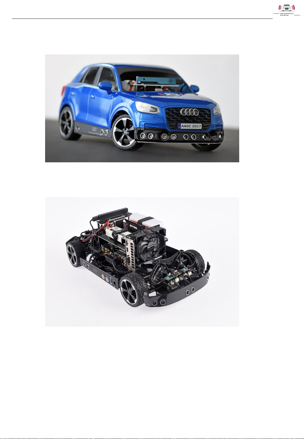
Figure 1: The AADC2017 car with AUDI Q2 cover
Figure 2: The AADC2017 car
Page 8
Hardware
31.05.2017
v1.7
Audi Autonomous Driving Cup 2017 - Hardware Description
7
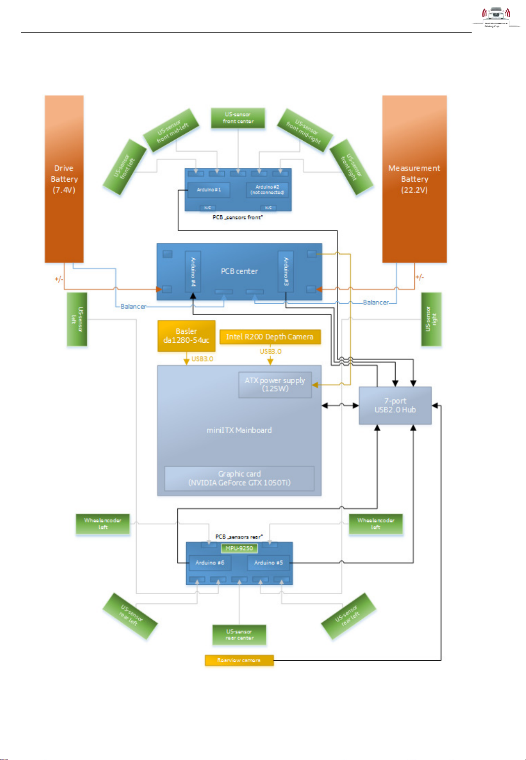
1.1 Schematic diagram
Figure 3: Schematic diagram
Page 9
Hardware
31.05.2017
v1.7
Audi Autonomous Driving Cup 2017 - Hardware Description
8
1.2 Computer
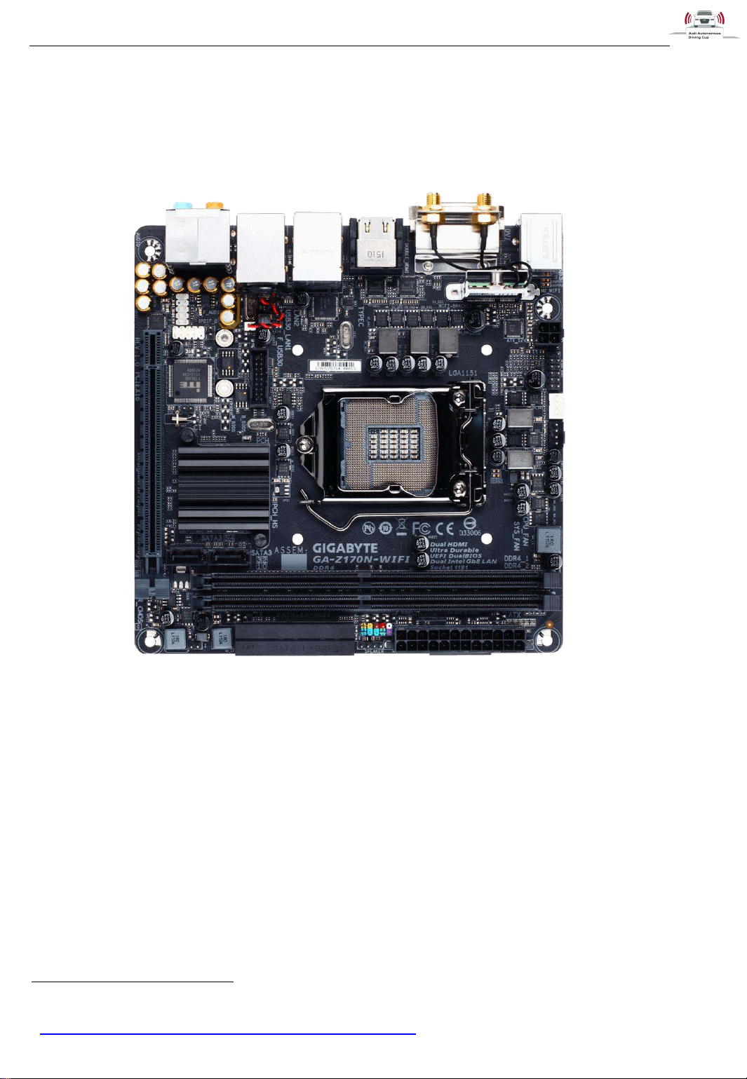
Built on a GIGABYTE GA-Z170N-WIFI miniITX mainboard, we can offer a wide range of PC
configurations.
Figure 4: Mainboard GIGABYTE GA-Z170N-W IFI1
Format: Mini-ITX
Chipset: Intel® Z170
Socket: 1151 for 6th generation Intel® CPUs ("Skylake")
RAM: 2× DDR4 in Dual-Channel
Slots (physical):
o 1× PCIe 3.0 x16
o 1× WiFi-/Bluetooth Module (incl. 802.11ac)
Internal Connectors:
o 6× SATA 6G
o 1× M.2 (PCIe 3.0 x4)
o 2× USB 3.0 (one header)
o 2× USB 2.0 (one header)
o 1× Fan (4-Pin PWM)
1
http://www.gigabyte.de/Motherboard/GA-Z170N-WIFI-rev-10%23ov
Page 10

Hardware
31.05.2017
v1.7
Audi Autonomous Driving Cup 2017 - Hardware Description
9
o Power/Reset/LED/Front-Audio
External Connectors:
o 1× PS/2 Keyboard/Mouse
o 4× USB 3.0
o 2 x Intel® GbE LAN chips (10/100/1000 Mbit)
o Wi-Fi 802.11 a/b/g/n/ac, supporting 2.4/5 GHz Dual-Band
o 2× WiFi Antenna (in bundle)
o 2× HDMI 1.4b
o 1× DVI
o 1× S/PDIF (optical)
o 5× Audio (7.1 Realtek ALC1150)
For this year’s competition, the mainboard is equipped with an Intel® Core i3-6100T CPU (3.2 GHz), a
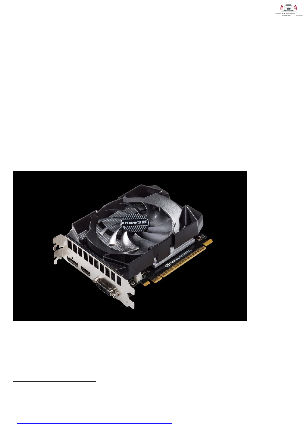
single 8 GB DDR4 PC-2133 RAM and a 128GB M.2 2280 SSD disk drive. In addition, there is a NVIDIA
GeForce GTX1050Ti graphics card mounted.
1.2.1 Graphics Card
The NVIDIA GeForce GTX 1050Ti graphics card specifications:
GPU Engine Specs:
o Base Clock (MHz) 1290
o Boost Clock (MHz) 1392
o NVIDIA CUDA® Cores 768
Memory Specs:
o Memory Speed 7 Gbps
o Standard Memory Config 4 GB GDDR5
o Memory Interface Width 128-Bit
o Memory Bandwidth 112 GB/sec
Technology Support:
o NVIDIA GPU Boost™ 3.0
o Microsoft DirectX 12 API with feature level 12_1
o OpenGL 4.5
o Bus Support PCIe 3.0
Display Support:
o Maximum Digital Resolution2 7680x4320 @ 60Hz
2
7680x4320 at 60Hz RGB 8-bit with dual DisplayPort connectors or 7680x4320 at 60 Hz YUV420 8-
bit with DisplayPort 1.3 connector.
Page 11
Hardware
31.05.2017
v1.7
Audi Autonomous Driving Cup 2017 - Hardware Description
10
o Standard Display Connectors DP 1.43, HDMI 2.0b, DL-DVI
o Multi Monitor yes
o HDCP 2.2
Dimensions:
o Height 4.38
o Length 5.7
o Width 2 Slot
Thermal Power Specs:
o Maximum GPU Temperature 97 °C
o Graphics Card Power 75 W
o Recommended System Power4 300W
Figure 55: NVIDIA GeForce GTX 1050Ti
3
DisplayPort 1.2 Certified, DisplayPort 1.3/1.4 Ready
4
Recommendation is made based on PC configured with an Intel Core i7 3.2 GHz processor. Pre-
built system may require less power depending on system configuration.
5
http://www.nvidia.de/graphics-cards/geforce/pascal/gtx-1050/
Page 12
Hardware
31.05.2017
v1.7
Audi Autonomous Driving Cup 2017 - Hardware Description
11
1.3 Arduino Micro
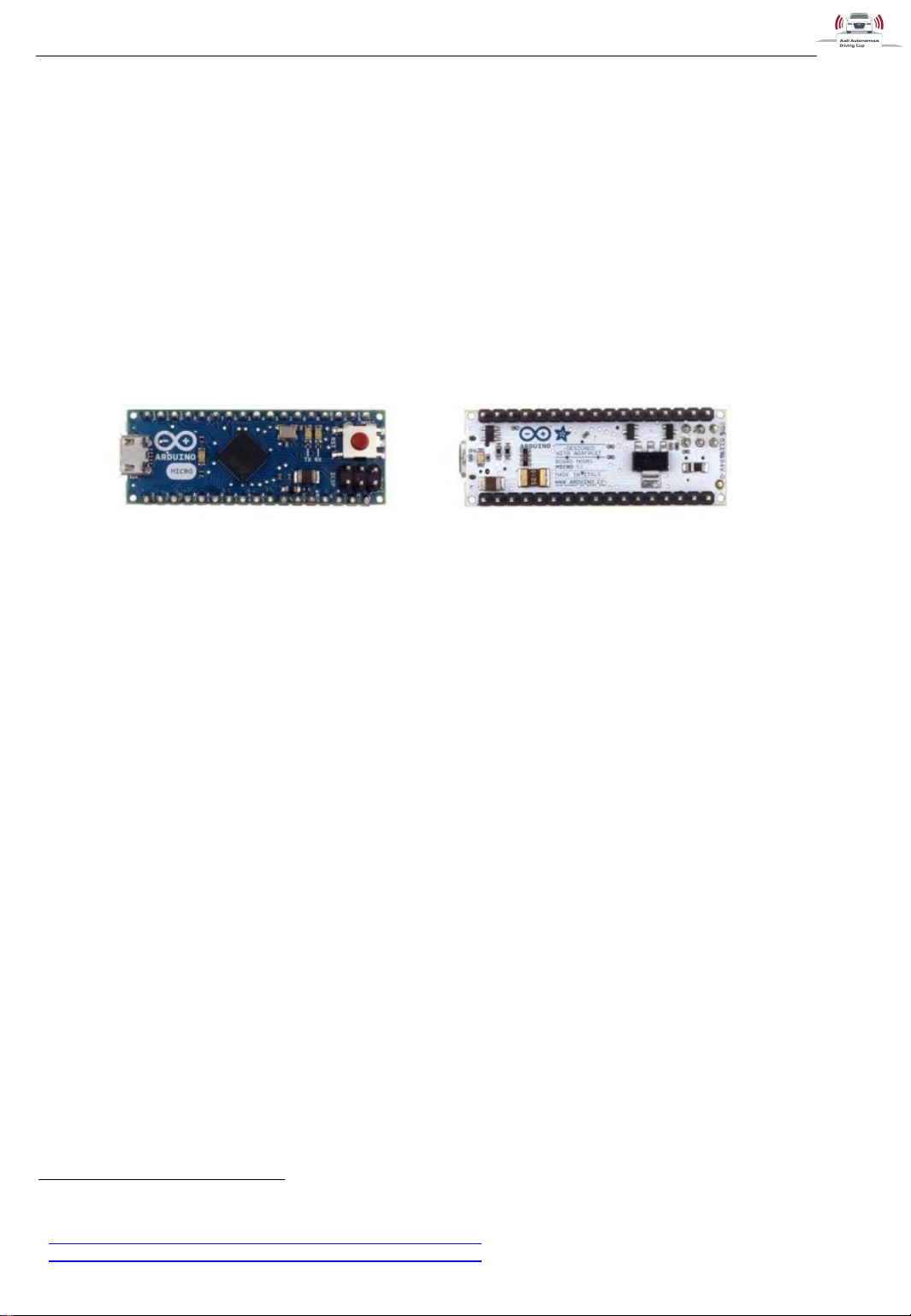
“The Arduino Micro is a microcontroller board based on the ATmega32u4 (datasheet), developed in
conjunction with Adafruit. It has 20 digital input/output pins (of which 7 can be used as PWM outputs
and 12 as analog inputs), a 16 MHz crystal oscillator, a micro USB connection, an ICSP header, and a
reset button. It contains everything that is needed to support the microcontroller - getting started simply
by connecting it to a computer via a micro USB cable. It has a form factor that enables it to be easily
placed on a breadboard.
The Micro is like the Arduino Leonardo in that the ATmega32u4 has a built-in USB communication,
eliminating the need for a secondary processor. This allows the Micro to appear to a connected
computer as a mouse and keyboard, in addition to a virtual (CDC) serial / COM port.” 6
Figure 6: Arduino Micro7
Microcontroller: ATmega32u4
Operating Voltage: 5V
Input Voltage (recommended): 7-12V (limits 6 - 20 V)
Digital I/O Pins: 20
PWM Channels: 7
Analog Input Channels: 12
DC Current per I/O Pin: 40 mA
DC Current for 3.3V Pin: 50 mA
Flash Memory: 32 KB (ATmega32u4) (4 KB bootloader)
SRAM: 2.5 KB (ATmega32u4)
EEPROM: 1 KB (ATmega32u4)
Clock Speed: 16 MHz
Dimensions (LxW): 48 mm x 18 mm
Weight: 13g
6
http://arduino.cc/en/uploads/Main/ArduinoMicroFront_450px.jpg
7
http://arduino.cc/en/uploads/Main/ArduinoMicroFront_450px.jpg
Page 13
Hardware
31.05.2017
v1.7
Audi Autonomous Driving Cup 2017 - Hardware Description
12
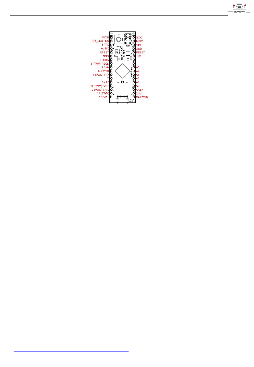
Figure 7: HC-SR04 Ultrasonic Sensor Arduino Micro Pinout8
8
http://arduino.cc/en/uploads/Main/ArduinoMicro_Pinout3.png
Page 14
Hardware
31.05.2017
v1.7
Audi Autonomous Driving Cup 2017 - Hardware Description
13
Figure 8: HC-SR04 Ultrasonic
Sensor9
HC-SR04 Ultrasonic Sensor
Operating Voltage: 4.5V to 5.5V
Quiescent Current: 1.5mA to 2.5mA
Working Current: 10mA to 20mA
Ultrasonic Frequency: 40Hz
Range: 2cm to 400cm
Resolution: 0.3cm
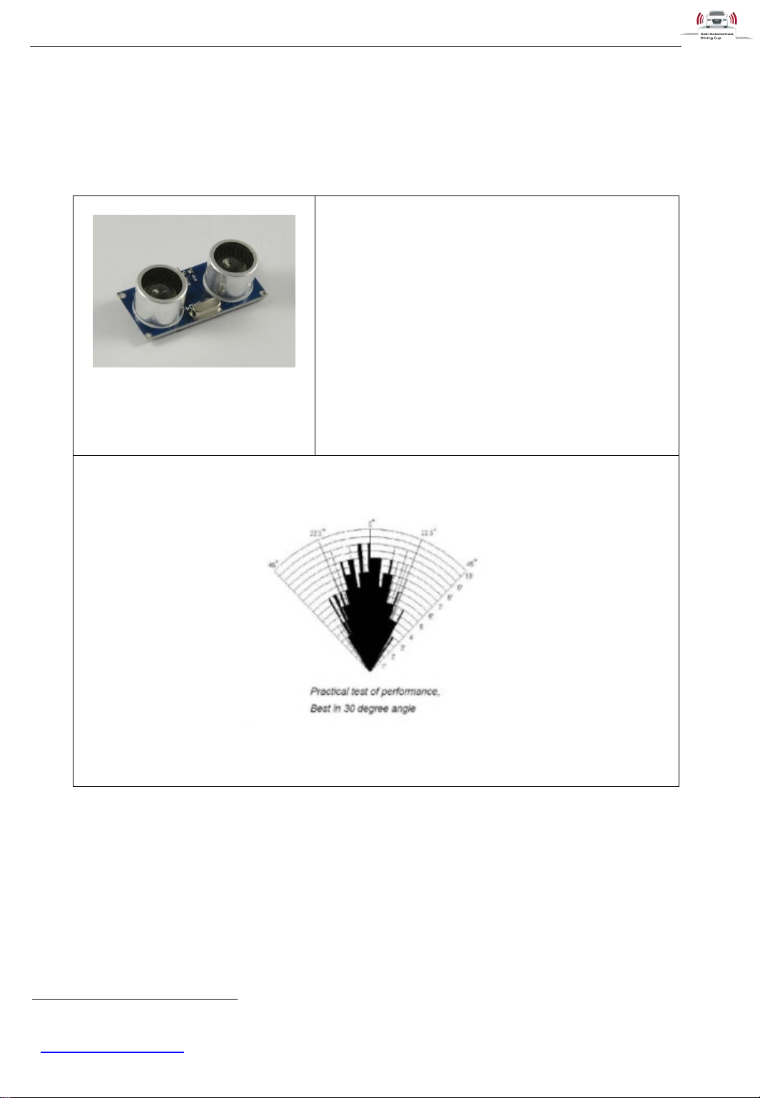
Measuring Angle: 30°
Effectual Angle: <15°
Dimension (mm): 45 x 20 x 15
Figure 9: Measuring Angle HC-SR04 (1)
1.4 Sensors
1.4.1 HC-SR04 Ultrasonic Sensor
9
HC-SR04 User's_Manual
Page 15
Hardware
31.05.2017
v1.7
Audi Autonomous Driving Cup 2017 - Hardware Description
14
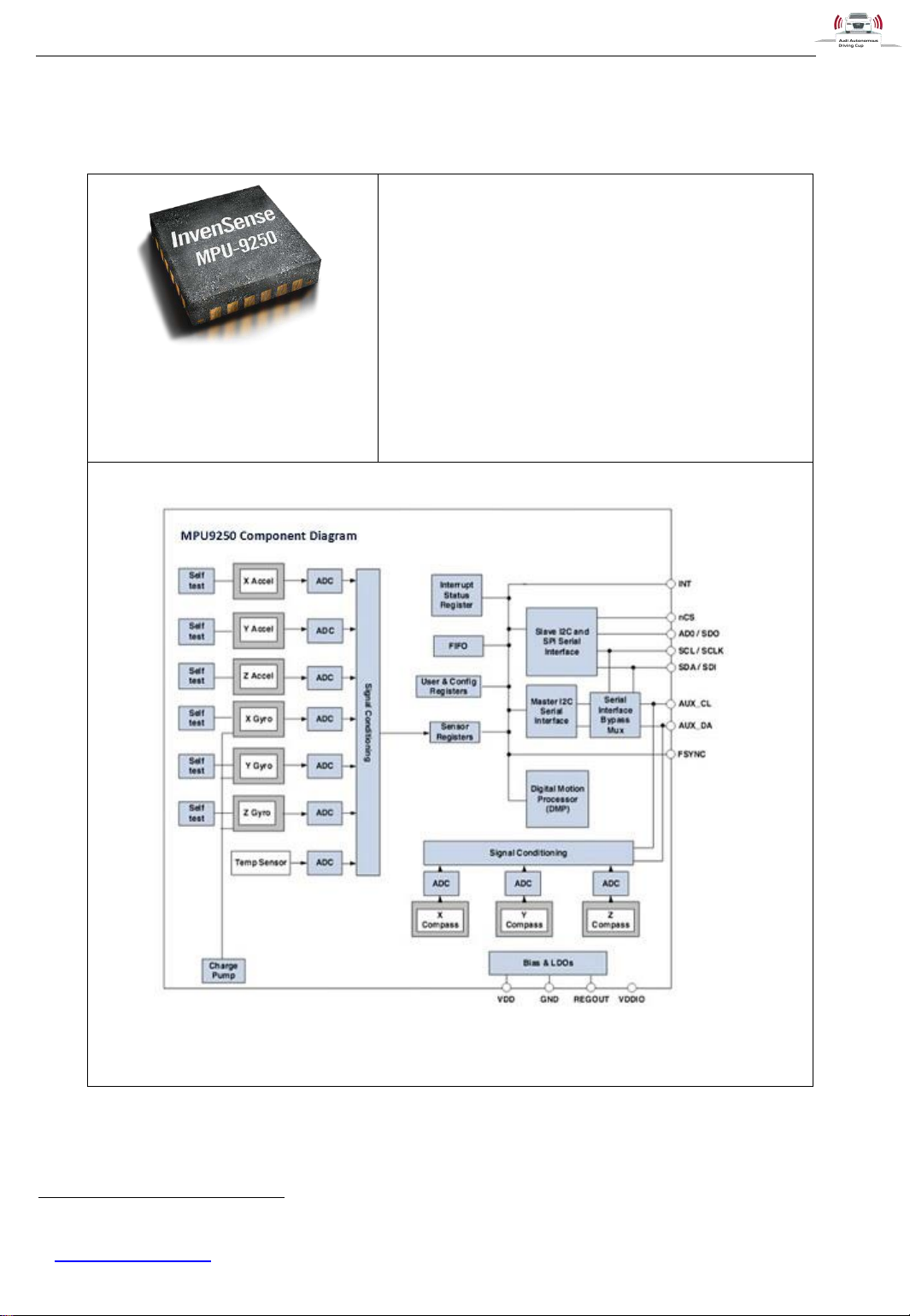
Figure 10: MPU-9250 9-axis
Gyro, Accelerometer and
Compass10
MPU-9250 MotionTracking Device
Digital-output X-, Y-, and Z-axis angular rate
sensors (gyroscopes) with a user-programmable
full-scale range of ±250, ±500, ±1,000 and
±2,000°/sec and integrated 16-bit ADCs
Digital-output triple-axis accelerometer with a
programmable full-scale range of ±2g, ±4g, ±8g and
±16g and integrated 16-bit ADCs
3-axis silicon monolithic Hall-effect magnetic sensor
with magnetic concentrator
Digitally programmable low-pass Gyroscope filter
Figure 11: Block Diagram MPU-9250
1.4.2 9-axis MotionTracking Device
10
Invensense MPU-9250
Page 16
Hardware
31.05.2017
v1.7
Audi Autonomous Driving Cup 2017 - Hardware Description
15
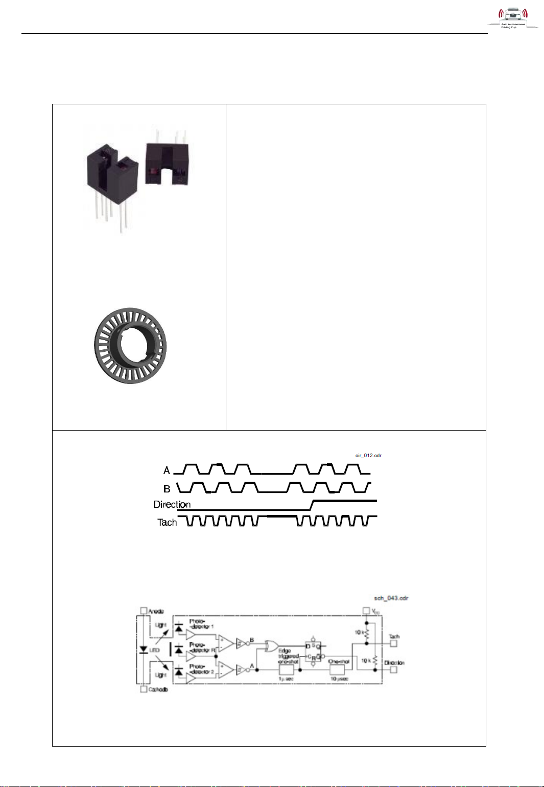
Figure 12: HOA0902-11
Transm issive Encoder Sensor
(2)
Figure 13: Encoder W heel
Honeywell HOA0902-11 – Transmissive Encoder
Sensor
Operating voltage: 4.5V to 5.5V (Detector)
Operating voltage: 1.6V (Emitter)
Revers Leakage Current: 10uA (Emitter)
Supply Current: 12mA
Slot width: 3.2 mm
Resolution: up to 0.457mm
Tach Pulse Width: 3…20 us
Encoder Wheel
The encoder wheel is a 3D printed BFFT in-house
development. It fits exactly onto the rear wheels and has
30 slots that result in 60 edges (rising and falling).
Figure 14: Output Timing Diagram HOA0902-11 (2)
Figure 15: Functional Block Diagram HOA0902 (2)
1.4.3 HOA0902-11 – Encoder
Page 17
Hardware
31.05.2017
v1.7
Audi Autonomous Driving Cup 2017 - Hardware Description
16
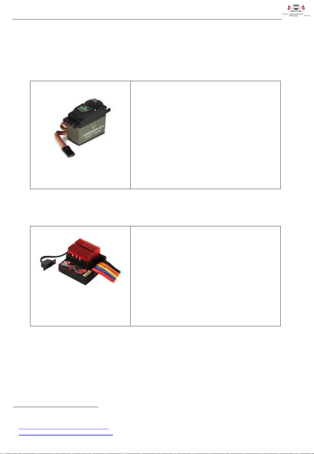
Figure 16: Absima "ACS1615SG"
Combat Series11
Absima "ACS1615SG" Combat Series
Operating voltage: 4 .8V to 6.0V
Pulling Force: 13kg to 15kg
Regulating time: 0,11s to 0,09s
Angle: 60°
Weight: 77 g
Figure 17: Robitronic Speedstar
Brushless Crawler12
Robitronic Speedstar Brushless Regler 8,5T
LiPo Cells: 2-3s
B.E.C. Voltage: 5V
B.E.C. Current: 3,0A
Ampacity: 260A / phase
(brushless)
Motor Turn Limit: 8,5 Turn (brushless)
Internal Resistance: 0,005 Ohm / phase
(brushless)
Dimensions (mm): 40 x 41 x 28.7
Weight: 43g
1.5 Actuators
1.5.1 Absima "ACS1615SG" Steering Servo
1.5.2 Robitronic Speedstar Brushless Speed Controller
11
Absima "ACS1615SG" Combat Series
12
Robitronic Speedstar Brushless Crawler
Page 18
Hardware
31.05.2017
v1.7
Audi Autonomous Driving Cup 2017 - Hardware Description
17
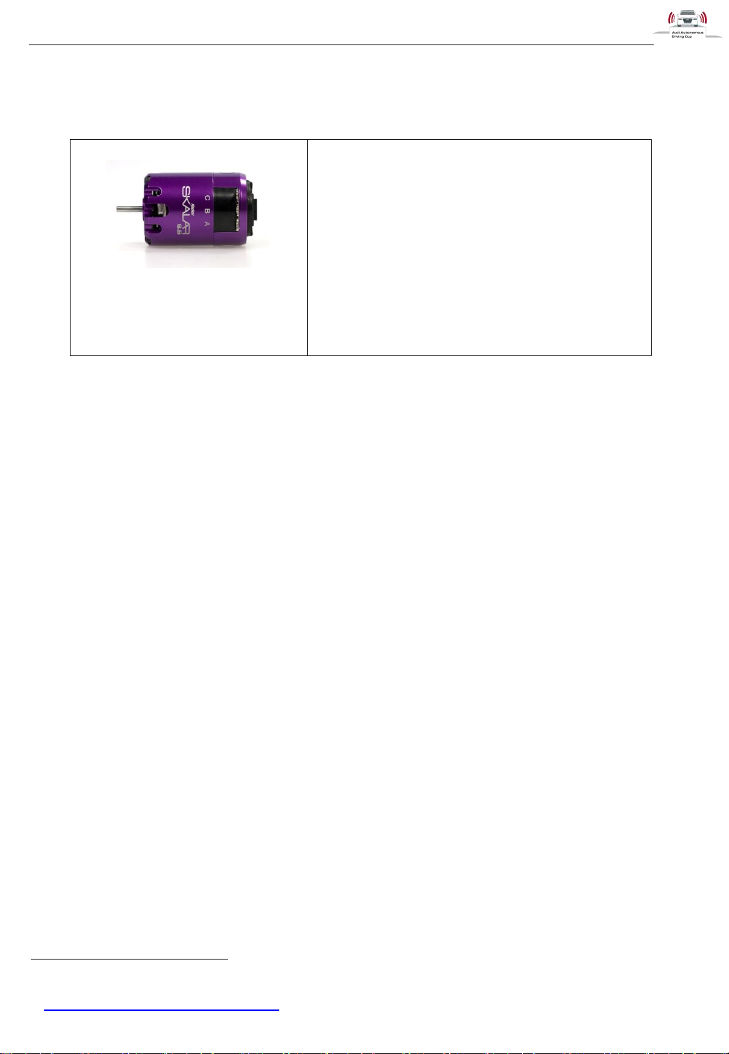
Figure 18: Hacker SKALAR 10
21.5 Brushless Motor13
Hacker SKALAR 10 21.5 Brushless Motor 1/10
Technology: Sensored, brushless
Scale: 1/10
Voltage: 3,2 - 11,1V
Length: 52.3mm
Diameter: 35.7mm
R/min per Volt: 2.100
Max. power: 149W
Turns: 21,5T
Weight: 162g
1.5.3 Motor Hacker Skalar 10
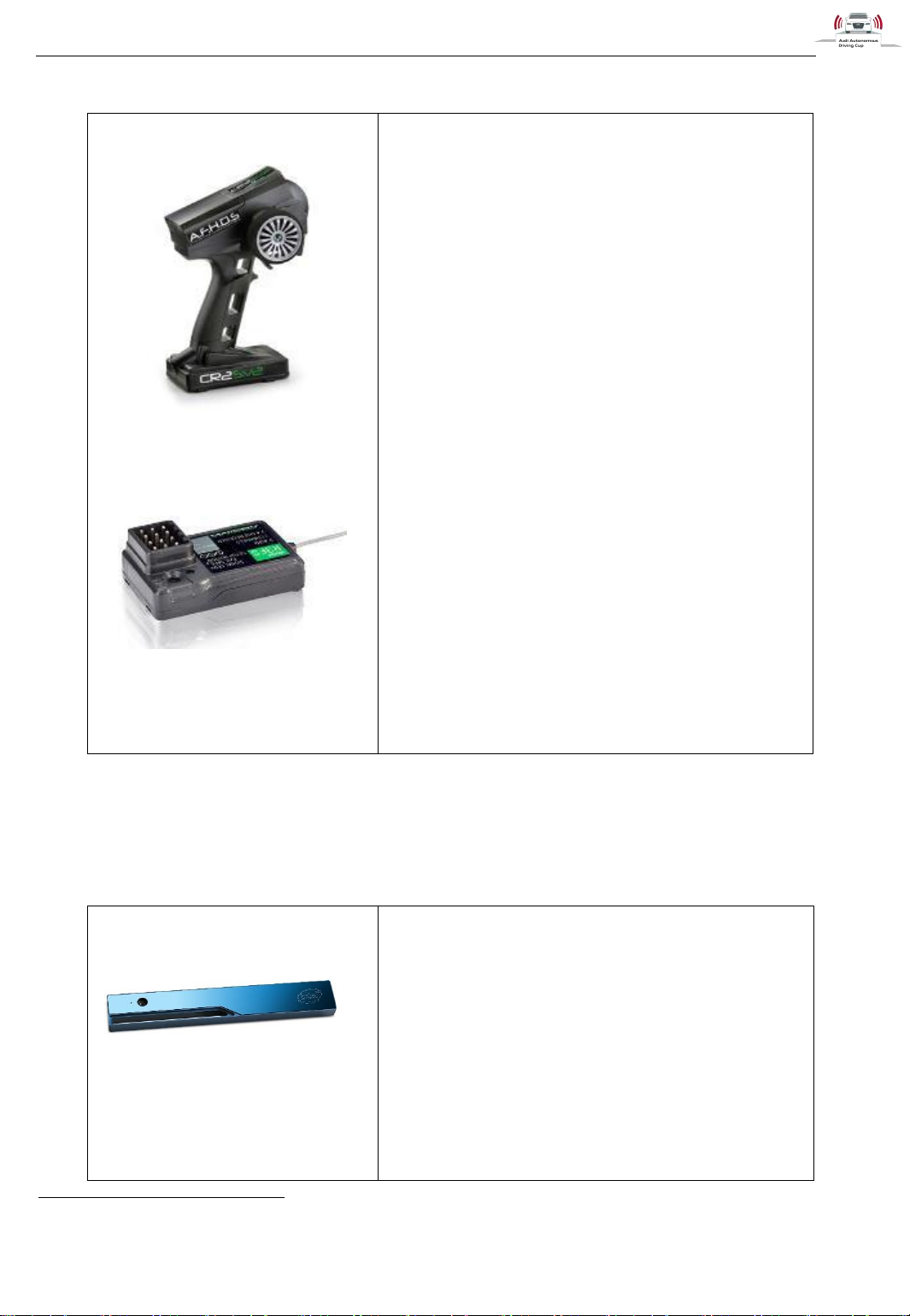
1.5.4 Absima CR2s V.2 Radio System
You can use the radio system to control the car manually. Please see chapter 2.4 Use Remote Radio
Controller for a detailed description.
13
Hacker SKALAR 10 21.5T Brushless Motor
Page 19
Hardware
31.05.2017
v1.7
Audi Autonomous Driving Cup 2017 - Hardware Description
18
Figure 19: Absima CR2S V.2 Radio
Transmitter
Figure 20: Absima CR2S V.2 Radio
Receiver
Absima CR2S V.2 Radio Transmitter
Channels: 2
RF power: less than 20 dbm
Modulation: GFSK
Code type: digital
Sensitivity: 1024
Low voltage warning: yes (less than 4,5 V)
Power: 6 V (1.5V AA *4)
ANT length: 26 mm
Dimensions (mm): 220 x 150 x 100
Weight: 328 g
Absima CR2S V.2 Radio Receiver
Channels: 3
Frequency band: 2.4 GHz
Modulation: GFSK
Sensitivity: 1024
RF receiver sensitivity: -100 dbm
Power: 4.5–7.2 V
ANT length: 26 mm
Dimensions (mm): 37.6 x 22.3 x 13
Weight: 5 g
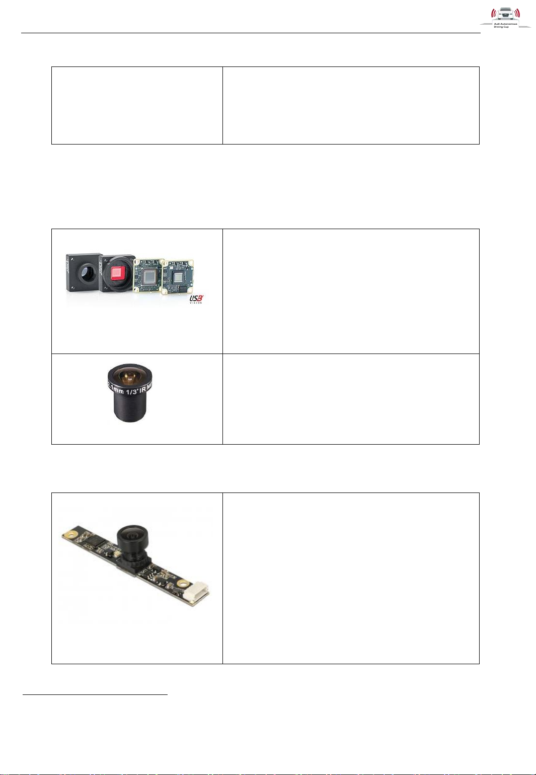
Figure 21: Intel®
RealSense™ R200 Depth
Camera14
Intel® RealSense™ R200 Depth Camera
Streams: RGB, Depth, 2x Infrared
RGB Stream
o Resolution (H x V pixels): 1920x1080,
640x480
o FOV (V x H x D): 43° x 70° x 77°
o FPS: 15, 30, 60
Infrared Stream
o Resolution (H x V pixels): 640x480,
492x372, 332x252
o FOV (V x H x D): 46° x 59° x 70°
o 30, 60
1.6 Cameras
1.6.1 Depth Camera Intel R200
14
https://click.intel.com/intel-realsense-developer-kit-r200.html
Page 20
Hardware
31.05.2017
v1.7
Audi Autonomous Driving Cup 2017 - Hardware Description
19
Depth Stream
o Resolution (H x V pixels): 628x468,
480x360, 320x240
o FPS: 30, 60
Infrared Projector
o FOV (V x H x D): 60° x 60° x 80°
Figure 22: Front Camera
Basler daA1280-54uc 15
Front Camera Basler daA1280-54uc
Resolution (H x V pixels): 1280 x 960px
Pixel Size horizontal/vertical: 3.75 µm x 3.75 µm
FPS: 45 in Car (54 max.)
Lens
Evetar M13B02118W
Iris: F1.8
Focal length: 2.1mm
FOV (V x H x D): 96° x 130° x 170°
Figure 23: RearView Camera
Delock 9636816
RearView Camera Delock 96368
Resolution (H x V pixels): max. 2592 x 1944, min.
160 x 144
FPS: max. 30, min. 7
80° fix focus
1.6.2 Front Camera Basler daA1280-54uc
Especially for road sign and lane detection, the car is equipped with an additional front camera.
1.6.3 RearView Camera Delock 96368
15
http://www.baslerweb.com/en/products/cameras/area-scan-cameras/dart/daa1280-54uc
16
http://www.delock.de/produkte/G_96368/merkmale.html?setLanguage=en
Page 21
Hardware
31.05.2017
v1.7
Audi Autonomous Driving Cup 2017 - Hardware Description
20
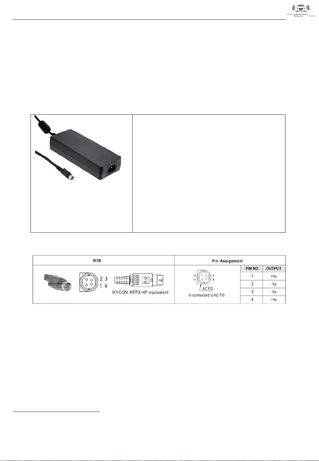
Figure 24: Mean Well
GST160A24-R7B17
(3- pin IEC plug i s include d in sc ope
of delivery)
Mean Well GST160A24-R7B
Input Voltage: 85~264VAC
Input AC Current: 1.85A / 115VAC
1A / 230VAC
Output DC Voltage: 24V
Output Rated Current: 6,67A
Output Rated Power (max.): 160W
Connection cable: UL2464 18AWGx4C
1200+-50mm for 15V~48V
Connection: R7B (male)
Dimensions (mm): 175x72x35
1.7 Power supply
1.7.1 External power supply unit
DC Output Plug:
Figure 2518: Pin Assignment of external power supply unit
17
https://www.conrad.de/de/tischnetzteil-festspannung-mean-well-gst160a24-r7b-24-vdc-667-a-160-w-1439251.html
18
http://www.meanwell.com/scripts/resource/pdfJS/web/viewer.html?f=GST160A&pdf=GST160A-SPEC.PDF
Page 22
Hardware
31.05.2017
v1.7
Audi Autonomous Driving Cup 2017 - Hardware Description
21
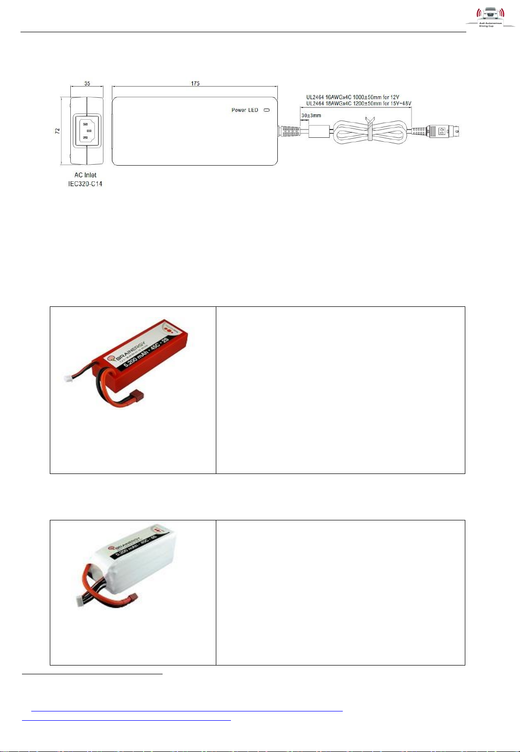
Figure 27: Yuki Model 2S
(7.4V) battery
Yuki Model 2S (7.4V) battery
Configuration: 2s1p
Nominal voltage: 7.4V
Rated capacity: 5.200mAh
Max. charge rate: 2C (10.4 A)
Cont. discharge rate: 45C (234 A)
Connection cable: silicon
Connection: Deans T-Plug
Balancer cable: PVC (JST XH)
Dimensions (mm): 137.5 x 46 x 25
Weight: 280g
Figure 28: Yuki Model 6S
(22.2 V) battery
Yuki Model 6S (22.2 V) battery
Configuration: 6s1p
Nominal voltage: 22.2 V
Rated capacity: 5.200mAh
Max. charge rate: 2C (10.4 A)
Cont. discharge rate: 45C (234 A)
Connection cable: silicon
Connection: Deans T-Plug
Balancer cable: PVC (JST XH)
Dimensions (mm): 137 x 43 x 60
Mechanical Specification:
Figure 2619: Mechanical Specification of external power supply unit
1.7.2 Battery for powertrain units
1.7.3 Battery for measurement units
19
http://www.produktinfo.conrad.com/datenblaetter/1400000-1499999/001439251-da-01-en-
MEAN_WELL_GST160A24_R7B_SNT_EXTERN_160W.pdf
Page 23
Hardware
31.05.2017
v1.7
Audi Autonomous Driving Cup 2017 - Hardware Description
22
Weight: 715 g
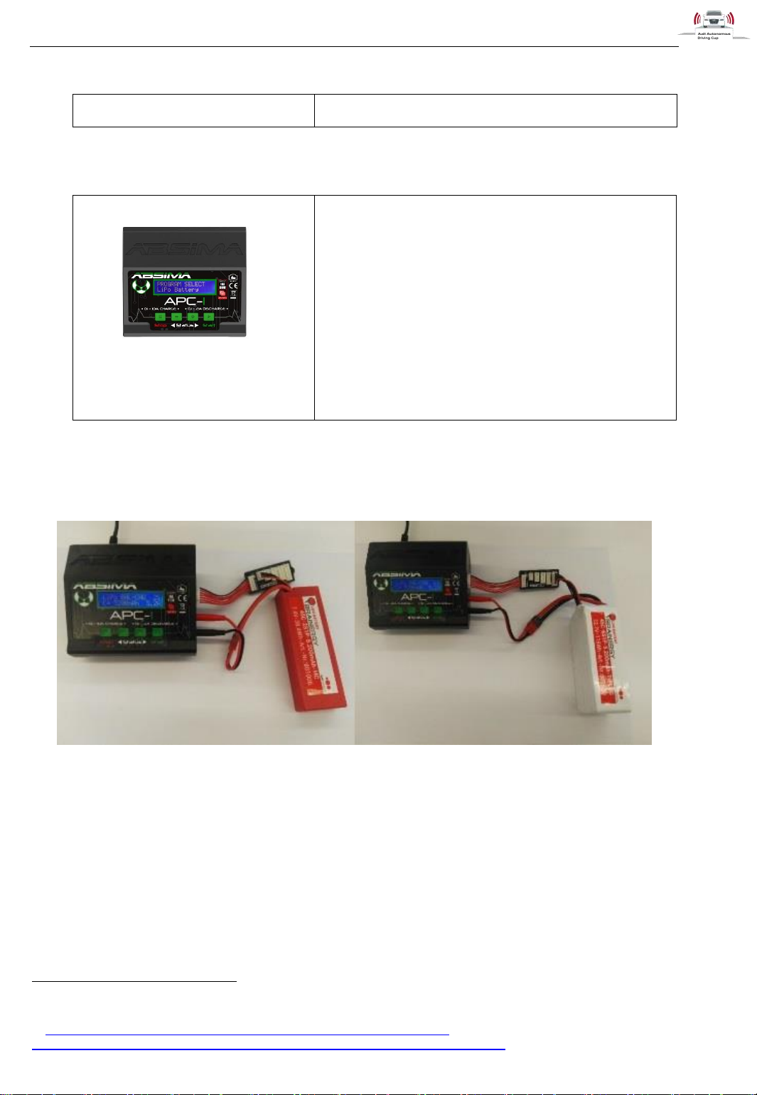
Figure 29: Absima APC-120
Charger Absima APC-1
Operating Voltage: DC 11.0 ~18.0 V
Input Voltage: AC 100 ~ 240 V
Circuit Power (charge): max. 80 W
Circuit Power (discharge): max. 5 W
Charge Current Range: 0.1 ~ 10.0 A
Discharge Current Range: 0.1 ~ 2.0 A
Lithium battery cell count: 1–6 cells
Dimensions (mm): 130×115×61
Weight: 380g
1.7.4 Charger
1.7.5 Charging Batteries
For 2S LiPo – accumulators: For 6S LiPo – accumulators:
Figure 30: Batteries (2S & 6S) connected to the charger
First, connect the battery to the charger as shown in Figure 30. Connect the charger to the power socket
and conjunct the balancer cable and the power cable from battery pack to the charge.
Always charge the batteries in balance mode. During this mode, the internal processor thereby controls
the charging current in order to normalize the voltage monitors each cell of the pack. You may not use
a different mode than balance mode to avoid a damage of the batteries.
Please refer to the manual of the charger for a detailed description of charging lithium batteries.
20
http://shop.absima.com/LADETECHNIK/Ladegeraete/Ladegeraet-APC-
1.htm?shop=absima&SessionId=&a=article&ProdNr=4000013&t=25&c=218&p=218
Page 24
Hardware
31.05.2017
v1.7
Audi Autonomous Driving Cup 2017 - Hardware Description
23
1.8 Printed Circuit Boards (PCBs)
1.8.1 PCB_Center
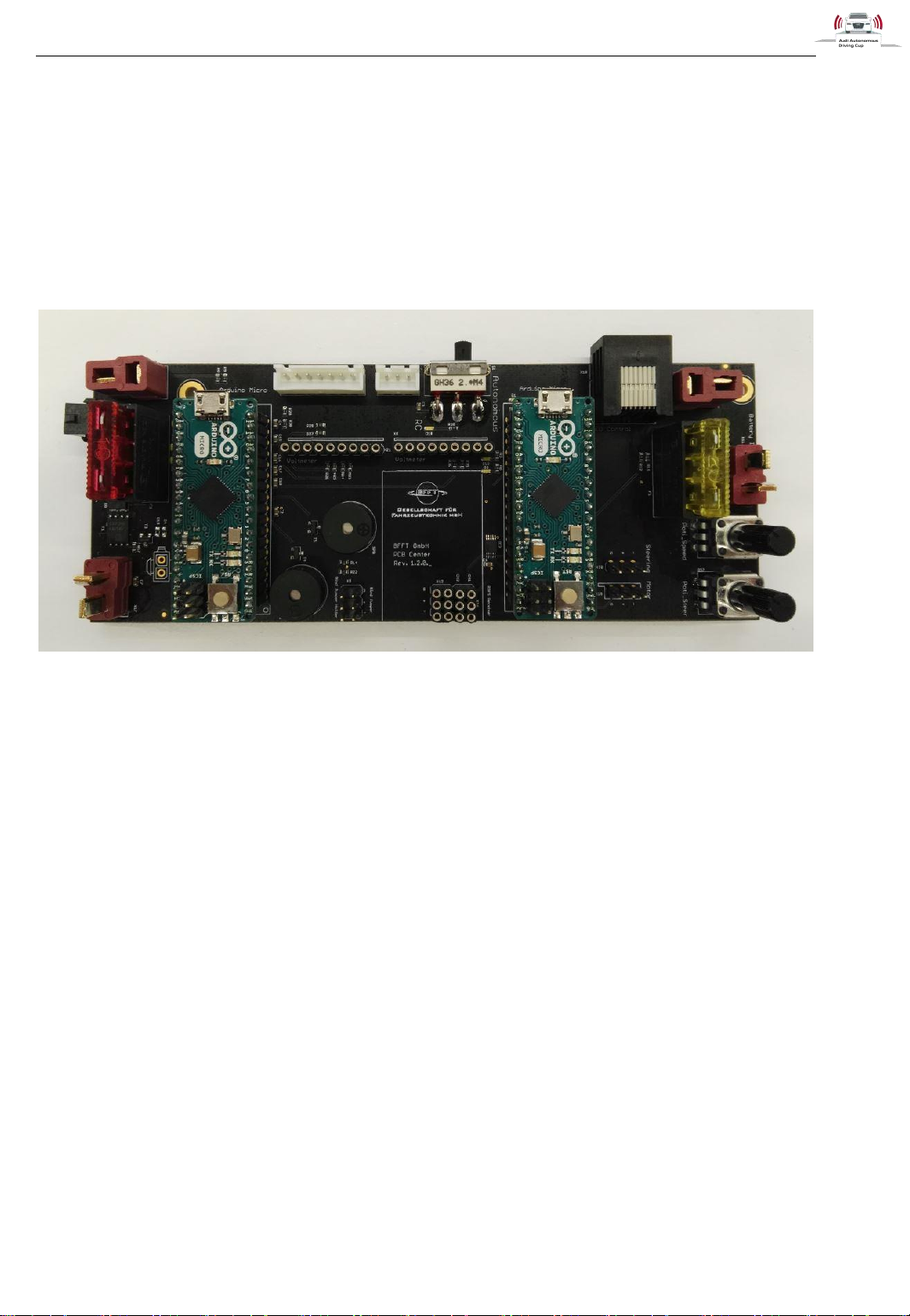
On this PCB there are plugged in two Arduino micros. The red circle marks the Arduino, which is used
for voltage measurement the blue one controls the lights, speed control and servo.
The yellow fuse is dimensioned with 20A and is used to protect the motor and speed controller. On the
left side, there is a red 10A fuse, which protects the ATX-power supply and the mainboard.
The tw0 9 pin connectors (green circle) are used for the two LiPo-Checkers.
In addition, there is a connector for the Bind-Jumper with an included holder for it.(yellow circle)
The connector on the right side of it is used for the R3FS-Reciever.
The two white connectors on the top of the board are used for the two different balancer cables. The
left one is for the 6S-battery the right one for the 2S-battery.
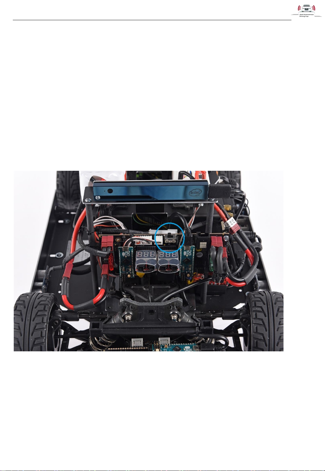
The switch next to them is for choosing between the two operation modes “radio-controlled” (left) or
“autonomous” (right).
The RJ45 socket is for the connection between the PCB_Center and the LED_Control.
The two red 2-pin plugs are for the 2 different batteries. The left one is used for the 22,2V battery the
right one for the smaller one 7,4V battery.
On the two red pin sockets you are able to connect the ATX power supply on the left side which is
plugged in at the mainboard and on the other side there is also a connector for the speed controller.
The black 4-pin socket is for the external power supply.
Page 25
Hardware
31.05.2017
v1.7
Audi Autonomous Driving Cup 2017 - Hardware Description
24
At the bottom on the right there are two 3-pin headers. The upper one is used for the steering and the
lower ne is used for the speed controller.
You can adjust the steering and speed with the two potentiometer on the right side.
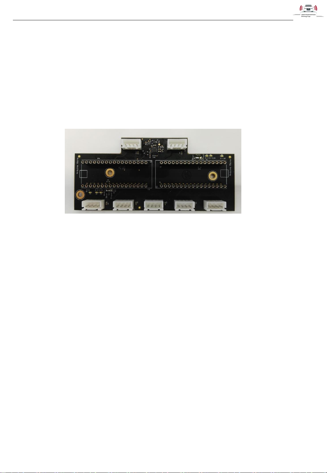
1.8.2 Sensor PCB
The Sensor PCB is used in the front and in the rear of the car.
These two printed circuit boards are almost identical. They differ from that only in that small detail that
one is jumpered for usage in the front and the other one is jumpered for usage in the rear.
1.8.2.1 Sensor PCB front
At this PCB there is connected one Arduino micro on the headers on the right side and five ultrasonic
sensors from the front spoiler are plugged in at the five 4-pin connector.
1.8.2.2 Sensor PCB rear
At this PCB there are connected five ultrasonic sensor and two wheel encoders.
There is one ultrasonic sensor on each side of the car and three of them are installed in the rear. The
wheel encoders are located in the inside of the tires.
There are also two Arduino micros on the PCB, which are connected on the USB Hub on the right side
of the car.
Page 26
Hardware
31.05.2017
v1.7
Audi Autonomous Driving Cup 2017 - Hardware Description
25
1.8.3 LED_Control
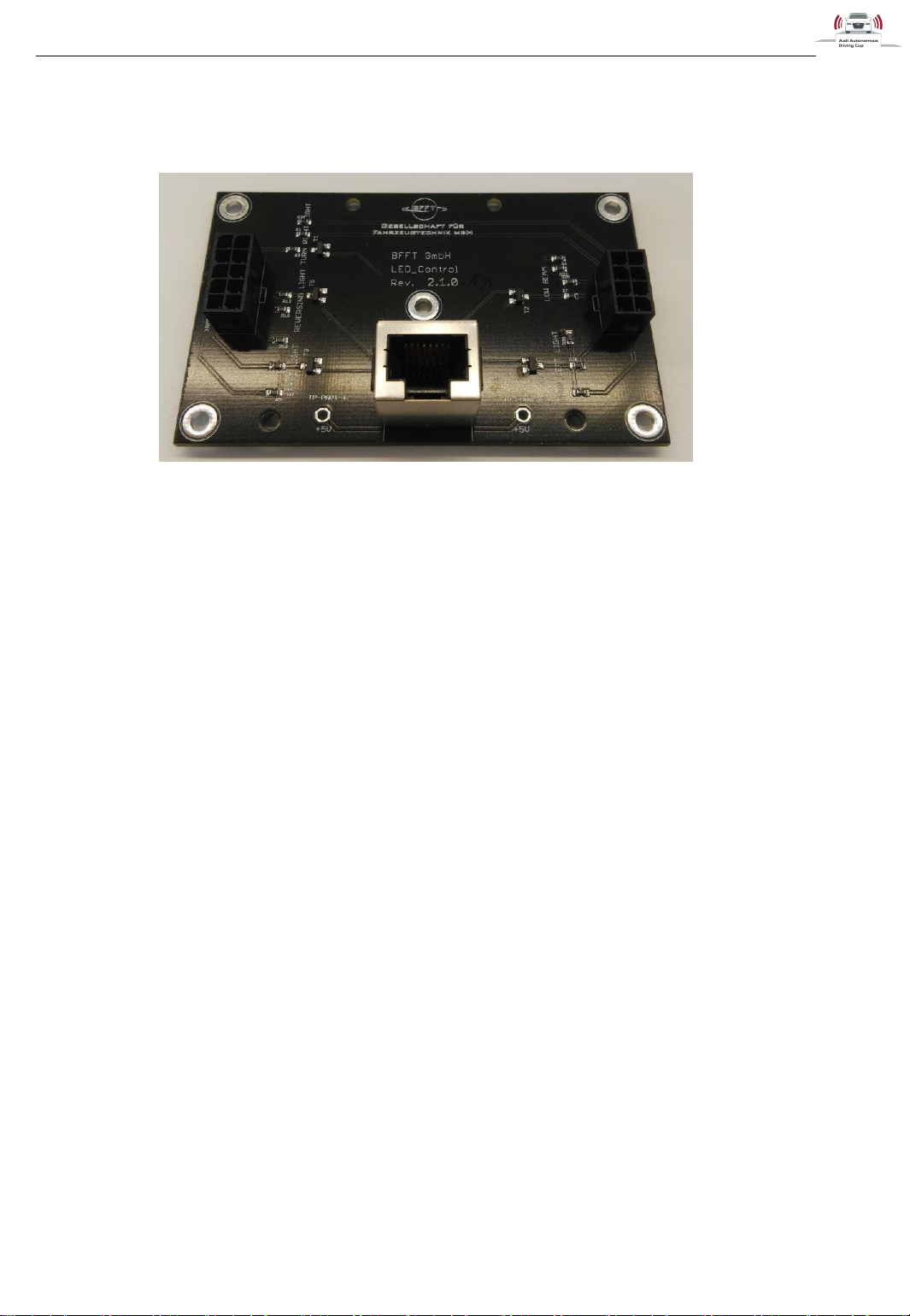
This PCB is placed in the back of the covering.
There are only three connectors on this PCB. The one RJ-45 socket, where you can plug in the cable
that is also connected to the PCB_Center.
The other two black headers are used to plug in the two different cable sets for the lights. The 10-pin
connector is used for the cable set to the LEDs in the back of the covering and the 8-pin connector is
used for the cable set to the LEDs in the front of the car.
Page 27
Starting the Car
31.05.2017
v1.7
Audi Autonomous Driving Cup 2017 - Hardware Description
26
2 Starting the Car
2.1 Connecting the batteries
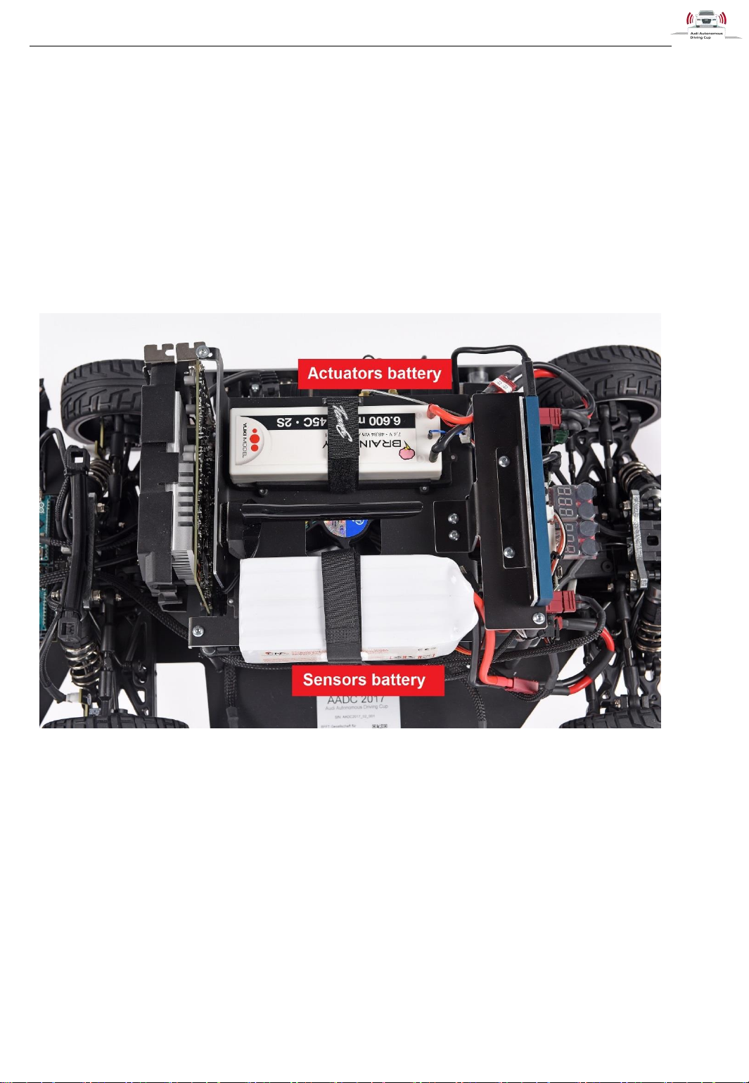
The car has two batteries:
The first one (2S LiPo, 7.4V) for power supply of the actuators (the speed-controller/motor
and the steering servo)
The second one (6S, 22.2V) for power supply of the PC, the Arduinos and the measurement
technology.
Figure 31: Top view batteries
You need to charge these two batteries, place them in the vehicle as shown in Figure 31: Top view
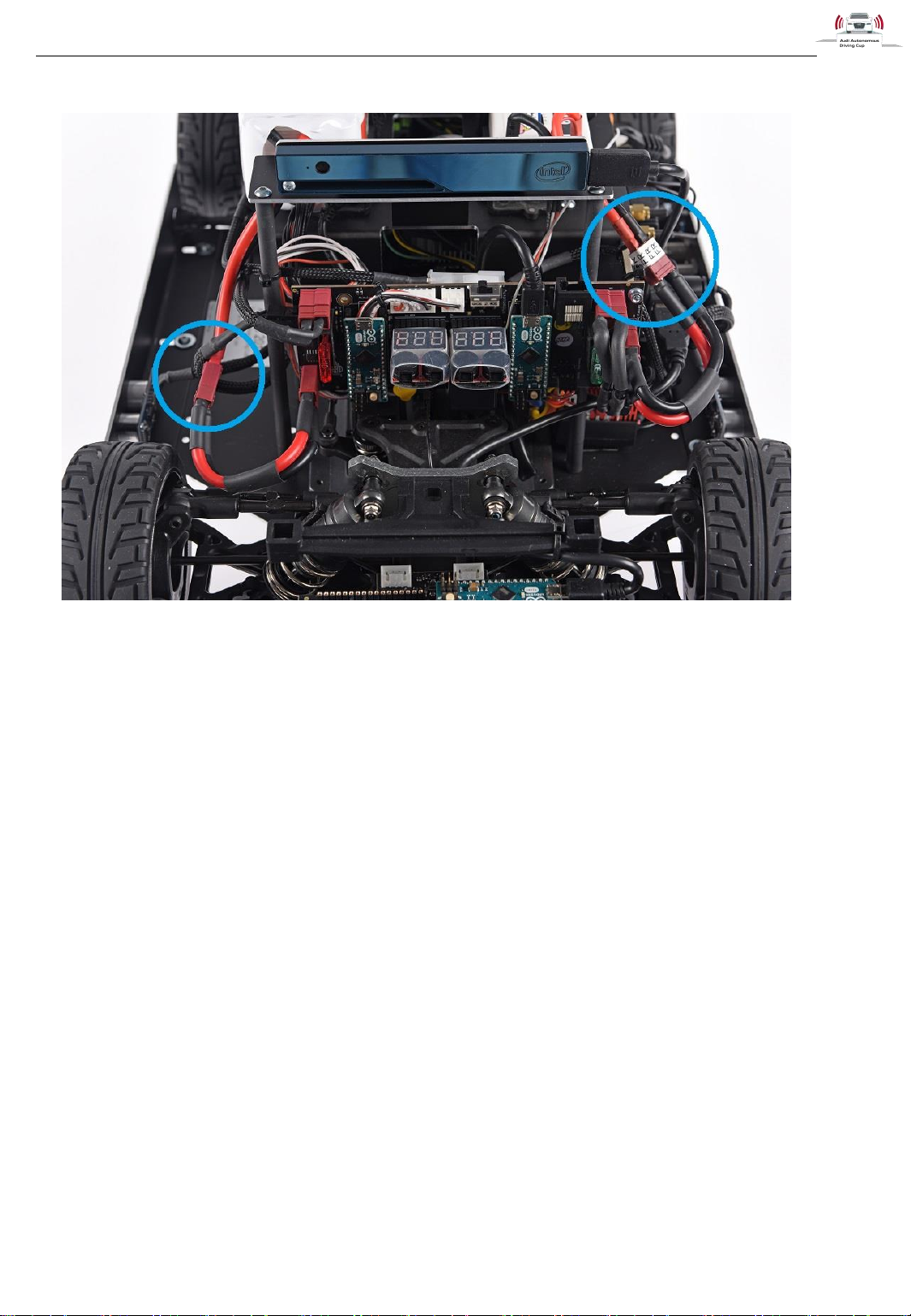
batteriesFigure 31 and connect thme to the board as shown in Figure 32.
Page 28
Starting the Car
31.05.2017
v1.7
Audi Autonomous Driving Cup 2017 - Hardware Description
27
Figure 32: Connecting the batteries
For connecting the batteries, make sure to connect the power cables (thick ones with red and black
cable, see blue circles above). Please always connect/disconnect these cables. Never unplug any
cable on the PCB, except balancer and USB-cables, otherwise might damage the PCB.
Afterwards connect the balancer cable (thin wires, black, white and red) and make sure that the
battery voltmeters are plugged into the connector. If you have everything connected properly, the
voltmeters will show the voltages of the batteries in big red letters.
YOU MUST USE THE BATTERY VOLTMETERS DURING USING THE CAR. OTHERWISE
THE BATTERIES COULD BE IRREVERSIBLE DAMAGED, OR COULD CATCH FIRE AND
DAMAGE THE CAR. EVERYTIME THE CAR IS USED THE VOLTMETER MUST SHOW A
VOLTAGE AND IF THEY START TO BEEP, DISCONNECT THE ACCORDING BATTERY
AND CHARGE IT.
2.2 Connecting the external power supply
You can also power the car externally by using the external power supply (24V/160W). In this case,
you can only remove the sensor battery. You still need the actuators battery for controlling the
actuators.
The external power supply and the Sensors battery, respectively, are hot pluggable. Therefore, you
are able to connect the external power supply while the battery is still connected and vice versa. That
enables you to change the Sensors battery without shutting down the PC.
Page 29
Starting the Car
31.05.2017
v1.7
Audi Autonomous Driving Cup 2017 - Hardware Description
28
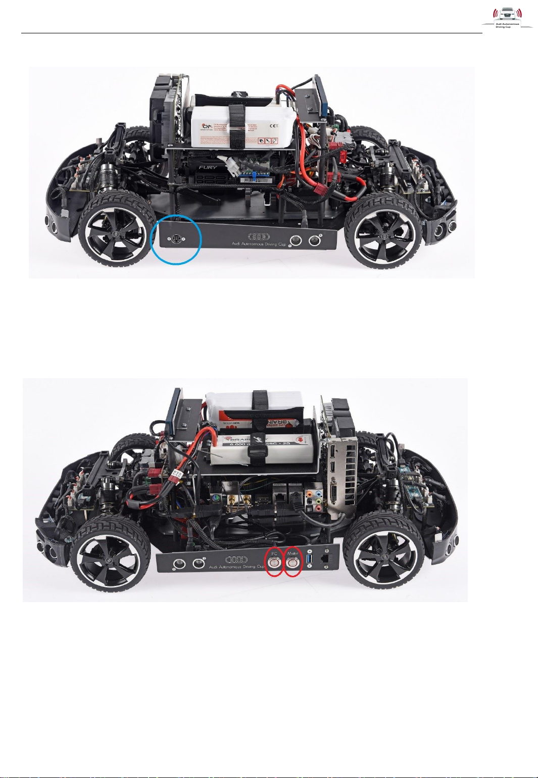
Figure 33: Connector for external power supply
2.3 Switching on
Figure 34: Switches on the car
The car has two switches to start the car. The switch labeled PC turns on the ATX power supply. It will
take 2 seconds after pressing the switch until the PC starts. Afterwards the USB ports are supplied
and the Arduinos consequently.
The other switch labeled Motor turns on the actuators. You need to press the switch in order to control
the actuators. We recommend turning off the actuators if you use the car on your desk to prevent
unexpected acceleration of the car.
Page 30
Starting the Car
31.05.2017
v1.7
Audi Autonomous Driving Cup 2017 - Hardware Description
29
2.4 Connecting other devices
An USB3.0 and a CAT5 RJ45 slot are also on the left side. To connect a monitor to the car, please
use the according slots of the graphic card. Note, the slots on the mainboard will not work if the gpu is
present.
2.5 Use Remote Radio Controller
To use the controller described in 1.5.4, you need to activate the remote receiver on the PCB center
by switching the RC/autonomous mode switch.
2.5.1 Activate Remote Radio Controller
Please follow the instructions below to use the radio controller.
Figure 35: Switch for RC/autonomous mode
1. First make the sure that the Bind Jumper is placed in the Bind Jumper Holder position and not
in the Bind Jumper position (i.e. the position next the remote radio receiver).
2. Then the mode switch has to be set to the RC position as shown in Figure 30. Afterwards a
LED right below the switch will turn on.
3. After setting the switch correctly, you need to reset the Arduino next to the switch by pressing
the Arduino Reset button. After this reset, the speed controller will initialize.
NOTE: When setting the Mode to Radio Controlled all the actuators commands from the Arduino and
from ADTF are ignored.
Page 31
Starting the Car
31.05.2017
v1.7
Audi Autonomous Driving Cup 2017 - Hardware Description
30
BIND BUTTON
POWER SWITCH
THROTTLE
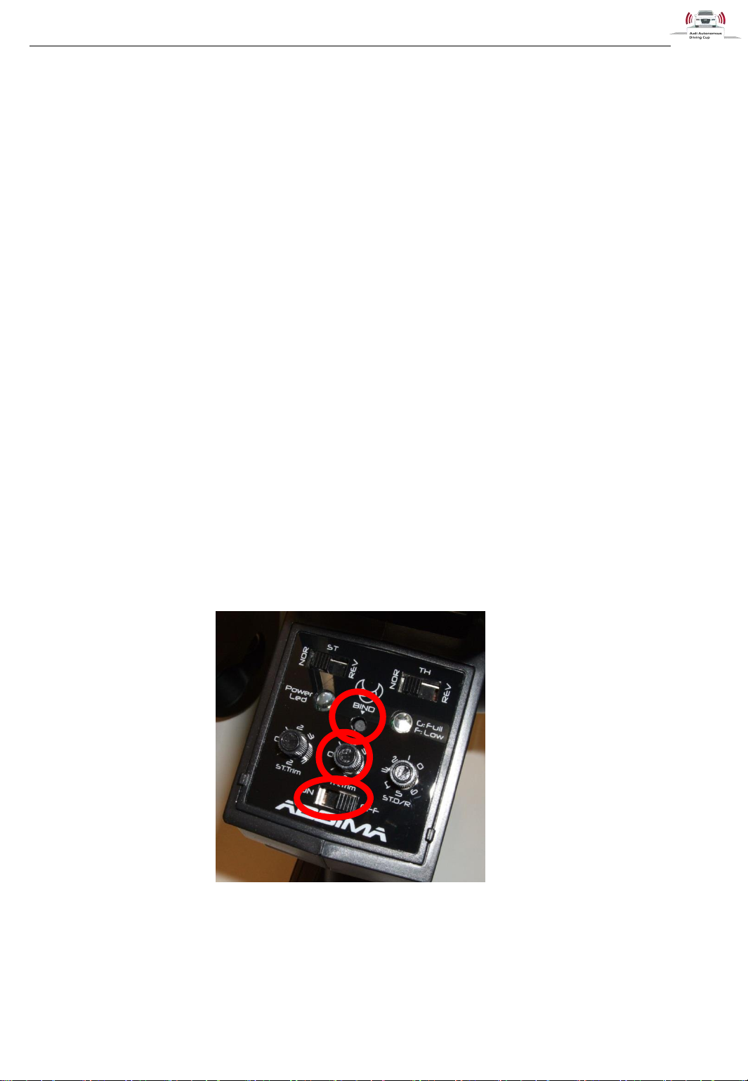
NOTE: Probably, the zero position of the Radio Controller System has to be adjusted. Take care of the
last point in Chapter 2.4.3.
2.5.2 Deactivate Remote Radio Controller
To deactivate the Radio Controller again and use the Arduino and ADTF commands, do the following
steps:
1. Set the mode switch to Autonomous.
2. Press the Arduino Reset Button to restart the Arduino and use the control commands from the
Arduino.
2.5.3 Bind Radio Controller to Radio Remote Receiver
If the Radio Remote Receiver (mounted on the board) needs to be bind to the Radio Controller again
to join the devices. Therefore, every controller can be used with every receiver by binding the two
devices. The binding also prevents receiving signals from the other controllers of the same model.
The binding was made for every car prior to the delivery, so it is not necessary to do the binding again.
If the binding was lost, follow the instructions below to match the devices again:
1. Make sure that the Mode Switch is set to Autonomous Mode
2. Set the Bind Jumper to the Bind Jumper position and not to the Bind Jumper Holder position.
3. Set the Mode Switch to the RC Mode; the red LED of the receiver should blink now.
4. Take the Remote Controller and make sure charged batteries are in the controller.
TRIM
5. Press and hold the Bind Button with a pencil or something other useful. While pressing the
Bind Button turn the Power Switch to ON. The red LED on the remote receiver on the car
should stop blinking.
6. Now, remove set the Mode Switch back to Autonomous Mode and place the Bind Jumper
back to the Bind Jumper Holder position again.
Figure 36: Radio Controller Buttons
Page 32

Starting the Car
31.05.2017
v1.7
Audi Autonomous Driving Cup 2017 - Hardware Description
31
7. Set The Mode Switch back to RC Mode.
8. Now you can turn on the controller again.
9. Normally, you need to calibrate the speed controller to the output of the radio controller. This
setup routine maps the maximum motor speed to the maximum PWM signal of the radio
controller system and the minimum motor speed to the minimum PWM signal of the radio
controller system. The PWM signals from the Arduino which are used in software driven mode
are different from the signals from the radio system, so normally the speed controller has to be
calibrated each time the mode is switched from Arduino to the Radio System and vice versa.
You can use a little trick can be used to avoid this effort.
When the speed controller is powered on (after pressing the Button Motor in the side sills), it
waits for the zero position (PWM signal which corresponds to motor speed zero set during
calibration procedure). During this time, the red LED of the speed controller is on. When the
speed controller gets the zero position it does some more beeping and the green LED is also
turned on and the speed controller works properly.
You can adjust this zero position by the potentiometer THROTTLE TRIM. Therefore, after
turning the power for the speed controller on (some first beeping from it) you can adjust this
potentiometer to set the correct zero position. If you found the correct position the speed
controller does some more beeping. Maybe you have to try this multiple times, each time
switch the motor on and try another position of the potentiometer.
Page 33

Calibration
31.05.2017
v1.7
Audi Autonomous Driving Cup 2017 - Hardware Description
32
3 Calibration
3.1 Speed Controller Setup
Usually, you do not need to calibrate the Speed Controller because this is already done prior to the
vehicle delivery. The Speed Controller Setup does a mapping from the received PWM Signal (from the
Arduino or the Radio Remote Control) to the minimum and maximum range of the motor.
If for any reasons, it is necessary to do this again, please follow these instructions:
1. Start the Car, Switch Speed Controller on, load and start the
SpeedControllerCalibrationConfiguration Project (Please see the
“AADC2017_Software_Description”). Make sure the Property Enable Speed Controller Fallback
of the Filter Car Control is turned to False.
2. Press the setup-button of the Speed Controller for more than a second. The green led will start
to indicate the pressing will start to light continuously if the button is released now.
3. Now the full throttle has to be transmitted to the steering controller. The red light will confirm the
full throttle position, then you have to release. The full throttle can be transmitted from ADTF
from the Car Control Filter by moving the bar to topmost position.
4. Now the maximum Reverse has to be transmitted and will be confirmed by red and green light.
Release to zero position again. The maximum reverse can be transmitted from ADTF from the
Car Control Filter by moving the bar to lowermost position.
5. The Controller will proceed with some blinking and peeping to confirm the calibration.
For further details, refer to the manual of the controller:
http://www.robitronic.com/en/manualrobitronic.html?file=files/anleitungen/robitronic/Speedstar_Brushless_Crawler_Manual.pdf
NOTE: The speed controller needs the zero position at startup phase. When the speed controller is
powered on it does some first beeping and the red LED is turned on and it waits for the zero position.
After receiving it the green LED turns on and it does some beeping. This zero position is set during the
described setup procedure.
3.2 Steering Calibration
The steering calibration consists mainly of a mapping from the servo angle to a valid curvature. You can
do this by the Steering Calibration Filter and is described in the “AADC2017_Software_Description”.
3.3 Adjustment with Potentiometers
On the Actuator Board are two potentiometer mounted which can be used for fine adjustment of the
steering servo and the speed controller.
Page 34
Calibration
31.05.2017
v1.7
Audi Autonomous Driving Cup 2017 - Hardware Description
33
Figure 37: Potentiometer in Zero Position
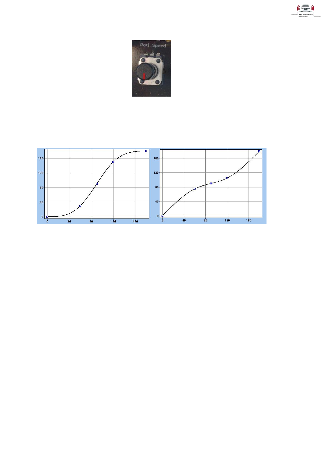
The potentiometer for the steering servo changes its zero position to make the car drive straight
ahead. The potentiometer for the speed controller modifies the mapping over the complete scope as
shown in Figure 33.
Figure 38: Modifications with speed controller potentiometer
Page 35

Troubleshooting
31.05.2017
v1.7
Audi Autonomous Driving Cup 2017 - Hardware Description
34
4 Troubleshooting
If any errors during using the car occur, please refer to the support forum at
https://www.audi-autonomous-driving-cup.com/ .
Page 36

Bibliography
31.05.2017
v1.7
Audi Autonomous Driving Cup 2017 - Hardware Description
35
Author:
BFFT Gesellschaft für Fahrzeugtechnik mbH
Dr.-Ludwig-Kraus-Straße 2
85080 Gaimersheim
www.bfft.de
5 Bibliography
1. Cytron Technologies. HC-SR04 User's_Manual. [Online] 05 01, 2013. [Cited: 6 3, 2015.]
https://docs.google.com/document/d/1Y-yZnNhMYy7rwhAgyL_pfa39RsBx2qR4vP8saG73rE/edit?pli=1.
2. Honeywell. HOA0902 Transmissive Encoder Sensor. [Online] [Cited: 6 3, 2015.]
https://www.google.de/url?sa=t&rct=j&q=&esrc=s&source=web&cd=2&cad=rja&uact=8&ved=0CCsQFj
AB&url=http%3A%2F%2Fmedia.digikey.com%2Fpdf%2FData%2520Sheets%2FHoneywell%2520Sen
sing%2520%26%2520Control%2520PDFs%2FHOA0902-
011.pdf&ei=CrhuVZvUGubZywOHn4Eo&usg=AFQjC.
3. Invensense. http://www.invensense.com/. MPU-6000 and MPU-6050 Product Specification
Revision 3.1. [Online] 11 24, 2011. [Cited: 6 3, 2016.]
http://43zrtwysvxb2gf29r5o0athu.wpengine.netdna-cdn.com/wp-content/uploads/2015/02/MPU-6000Datasheet1.pdf.
 Loading...