

Page 1
Self Study Programme 623
For internal use only
Audi A3 Cabriolet ’14
Audi
Service Training
Page 2
Audi A3 Cabriolet ’14
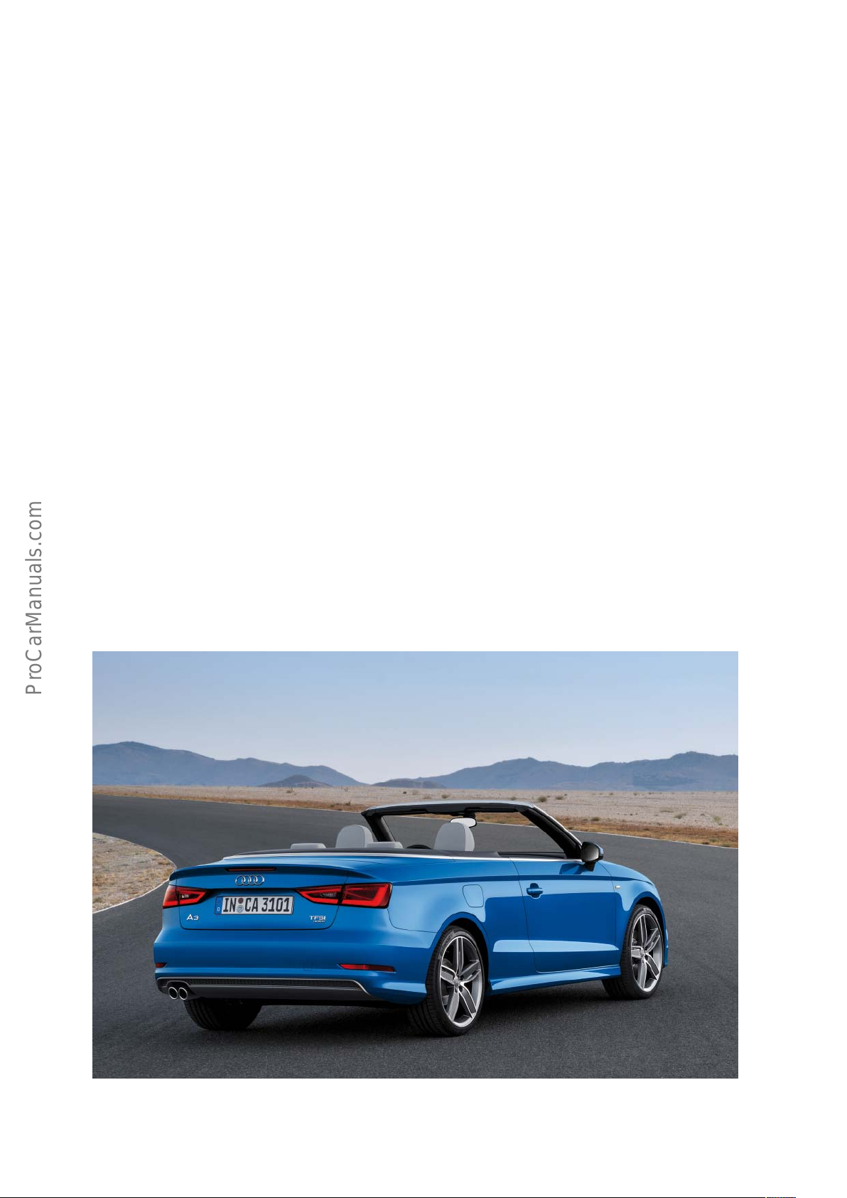
Sporty, elegant and multi-faceted – introducing the new Audi A3
Cabriolet ’14. This compact four-seater impresses at first glance
with its flowing lines and soft top. It is also at the top of its class
technically – with systematic lightweight design, new engines,
multi-faceted networking and high-performance assistance
systems. The Audi A3 Cabriolet ’14 completes the A3 family.
The new Audi A3 Cabriolet '14 has grown compared to the
outgoing model – in length, wheelbase and width. Only its height
has been reduced – to give the four-seat convertible a more elegant
and sporty look on the road.
The new Audi A3 Cabriolet ’14 has a soft top that is stretched over
a lightweight magnesium-steel kinematic mechanism, and it
complements the car's design perfectly. At the press of a button,
the top opens or closes electro-hydraulically in less than 18
seconds, even while driving up to 50 kph.
The fully automatic soft top has a glass rear window. A fully automatic acoustic top is available as an alternative; it has a thicker
inner foam layer which reduces the already low interior noise level
of the Audi A3 Cabriolet '14 even more. An active rollover protection system protects the occupants in case of a rollover accident.
Elegantly drawn lines and clean surfaces also typify the interior
design of the new Audi A3 Cabriolet '14. The optional lighting
package includes, for the first time, a touch-sensitive switch for
the reading lights.
As in every Audi, workmanship quality is uncompromisingly high,
and the car's controls are simple, intuitive and convenient. It oers
enough space for four adults, and the seatbacks of the two rear
seats can be folded down to create a wide through-load area. The
steering wheel and seats are new designs, and the also new electro-mechanical parking brake is operated by a pushbutton on the
centre console.
All engines in the new Audi A3 Cabriolet '14 combine the technologies of direct injection, turbocharging and a start-stop-system.
On average, the three engines oered at market launch have
twelve percent better fuel economy than the engines in the outgoing model – and they do so while improving driving performance.
The chassis of the new Audi A3 Cabriolet '14 impresses with
sophisticated technology that delivers sporty handling, superior
vehicle safety and a high level of comfort. Some of the components of the MacPherson front suspension are made of aluminum;
the four-link rear suspension handles longitudinal and transverse
forces separately. The power steering system features an ecient
electromechanical drive.
The ESC stability control system integrates an electronic limited
slip dierential – this makes handling even smoother and safer at
the vehicle’s cornering limits while driving fast through curves. The
brakes are powerful and durable.
623_001
2
Page 3

!
Contents
Introduction
In brief _______________________________________________________________________________________________________________________________________________________ 4
Body
Body structure/materials ___________________________________________________________________________________________________________________________________ 6
Body structure/reinforcements ____________________________________________________________________________________________________________________________ 8
Convertible top
Variable convertible top well _____________________________________________________________________________________________________________________________ 12
Convertible top box lid/service position _________________________________________________________________________________________________________________13
Convertible top frame _____________________________________________________________________________________________________________________________________14
Hydraulic unit _______________________________________________________________________________________________________________________________________________ 15
Convertible top control system
Installation locations of the convertible top control unit ______________________________________________________________________________________________ 16
Convertible top operation _________________________________________________________________________________________________________________________________ 18
Components of the convertible top control unit ________________________________________________________________________________________________________30
Emergency operation ______________________________________________________________________________________________________________________________________42
Data bus overview __________________________________________________________________________________________________________________________________________45
Occupant safety
Components ________________________________________________________________________________________________________________________________________________46
System overview ___________________________________________________________________________________________________________________________________________48
Side airbag __________________________________________________________________________________________________________________________________________________ 50
Electrical wiring loom for side airbag ____________________________________________________________________________________________________________________51
Rear side airbag crash sensor, driver side G256 ________________________________________________________________________________________________________51
Rollover protection ________________________________________________________________________________________________________________________________________ 52
Cassettes with anti-roll bars ______________________________________________________________________________________________________________________________53
Rollover protection trigger, driver side N646 and rollover protection trigger, passenger side N647 _____________________________________________ 53
Deployed rollover protection system N647 _____________________________________________________________________________________________________________54
Resetting a deployed anti-roll bar ________________________________________________________________________________________________________________________ 55
Diagnostics _________________________________________________________________________________________________________________________________________________ 55
Engine/gearbox combinations
Petrol engines ______________________________________________________________________________________________________________________________________________56
Diesel engines ______________________________________________________________________________________________________________________________________________57
Suspension
Overall concept ____________________________________________________________________________________________________________________________________________58
Overview ____________________________________________________________________________________________________________________________________________________ 59
Electrical system
Installation locations of control units ___________________________________________________________________________________________________________________ 60
Topology ____________________________________________________________________________________________________________________________________________________62
Air conditioning
Introduction ________________________________________________________________________________________________________________________________________________64
Operation ___________________________________________________________________________________________________________________________________________________65
Infotainment
Sound system _______________________________________________________________________________________________________________________________________________68
Aerial system _______________________________________________________________________________________________________________________________________________70
Overview of versions _______________________________________________________________________________________________________________________________________72
Service
Inspection and maintenance ______________________________________________________________________________________________________________________________ 74
Self Study Programmes ___________________________________________________________________________________________________________________________________ 75
• The Self Study Programme teaches a basic knowledge of the design and mode of operation of new models,
new automotive components or new technologies.
It is not a Repair Manual! Figures are given for explanatory purposes only and refer to the data valid at the
time of preparation of the SSP.
Content is not updated.
For further information on maintenance and repair work, always refer to the current technical literature.
Note
Reference
3
Page 4
!
Introduction
In brief
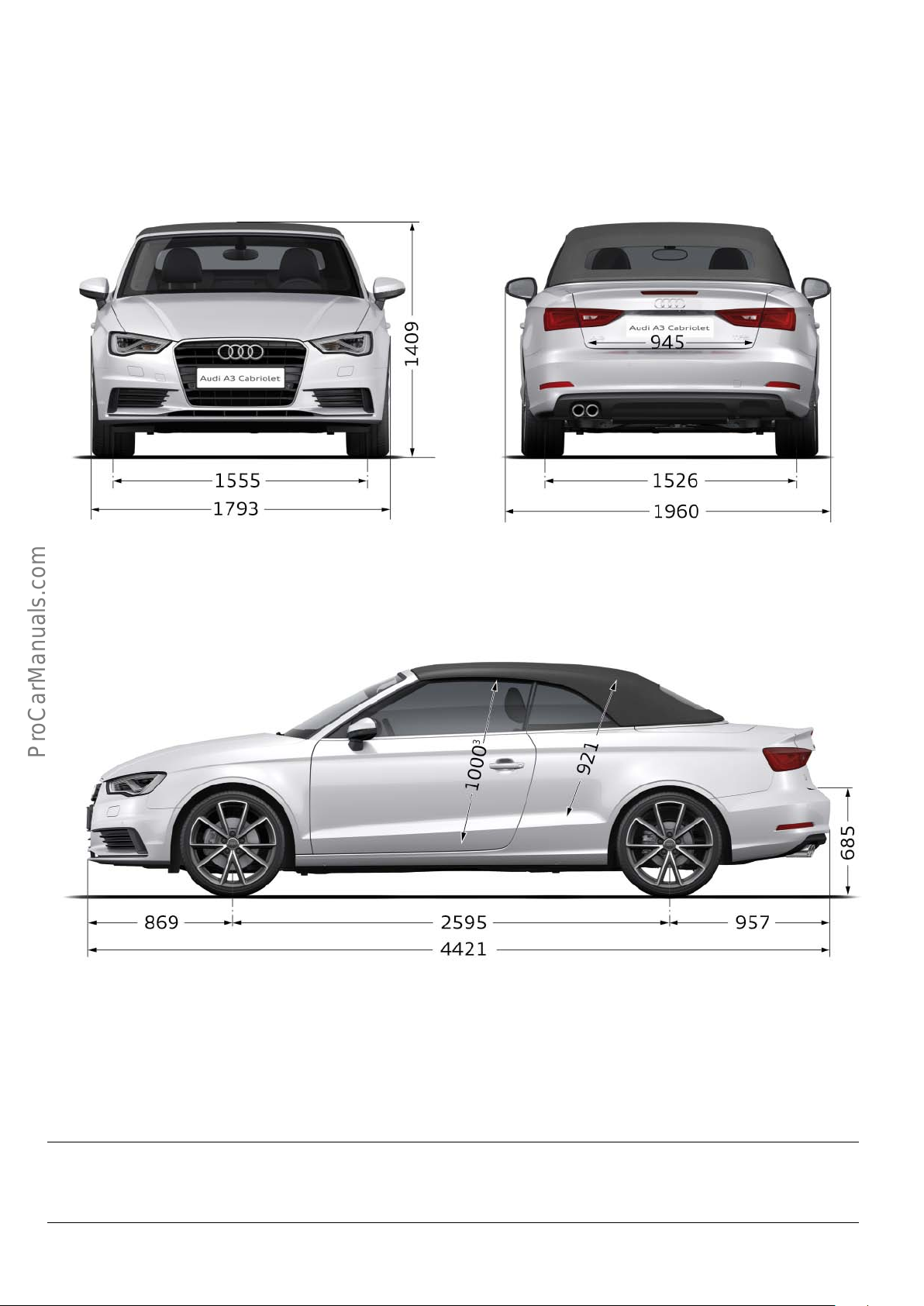
Dimensions
623_002
623_003
Note
The graphics and illustrations shown in this self study programme are basic representations and are given to help understand
concepts.
4
Page 5
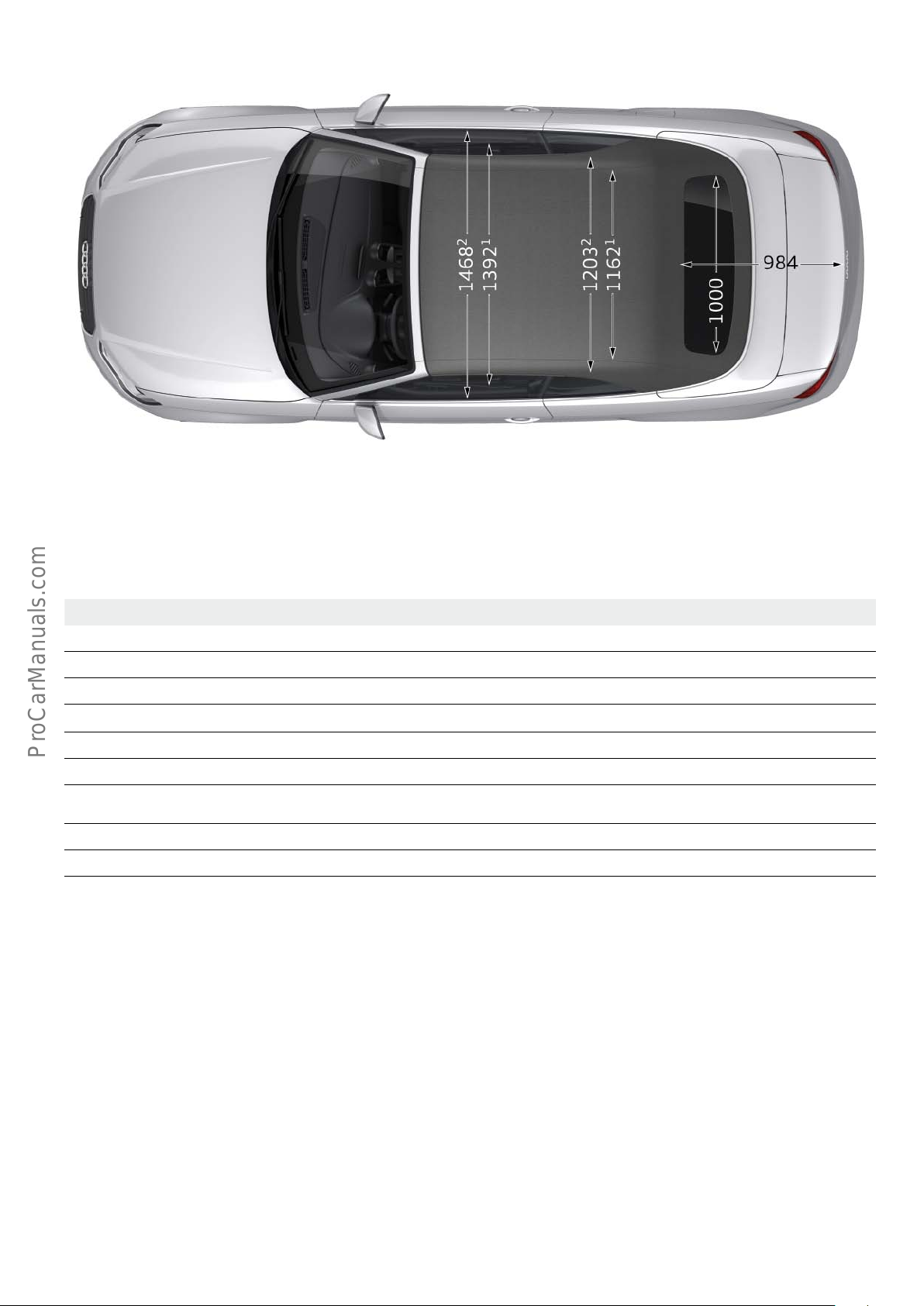
Length in mm 4421 Cabin width, front in mm 1468
Width in mm 1793
5)
Cabin width, rear in mm 1203
Height in mm 1409 Headroom, front in mm 1000
Track width, front in mm 1555 Headroom, rear in mm 921
Track width, rear in mm 1526 Load sill height in mm 685
Wheelbase in mm 2595 Boot capacity in l 320
Trailer load in kg
with brake at a gradient of 8%
Kerb weight in kg 1430
1800
4)
4)
Tank capacity in l 50
Drag coecient in c
w
Max. gross weight in kg 1930
623_004
0.30
1)
Shoulder room width
2)
Elbow room width
3)
Maximum headroom
4)
with a 1.8l TFSI engine developing 132 kW at 250 Nm
5)
excluding mirror
All dimensions are given in millimetres and refer to the unladen weight of the vehicle.
5
Page 6
Body
Body structure/materials
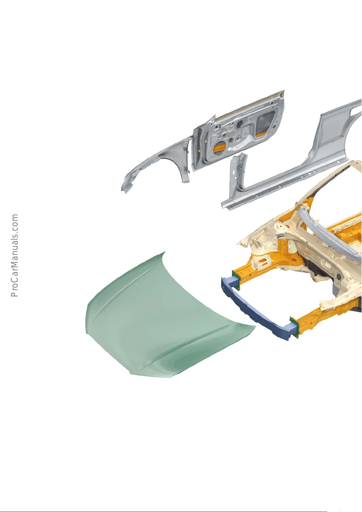
The body of the Audi A3 Cabriolet ’14 rigid and crash-safe body
structure designed on the basis of the Audi A3 saloon. Thanks to
Audi ultra-lightweight technology, convertible-specific elements
such as the A post, front roof frame, rear bulkhead and the
underbody are designed so they do not add weight to the
A3 Cabriolet ’14.
Including its special reinforcements, which deliver high torsional
stiness, the body-in-white weighs 30 kg less than the
outgoing model.
Attachments
The attachments, specifically the wings, doors, convertible top box
lid, rear hatch and bumper cross-members, are of lightweight steel
construction.
The following components of the A3 Cabriolet ’14 are made from
aluminium:
• Bonnet
• Front bumper cross-member
6
Page 7
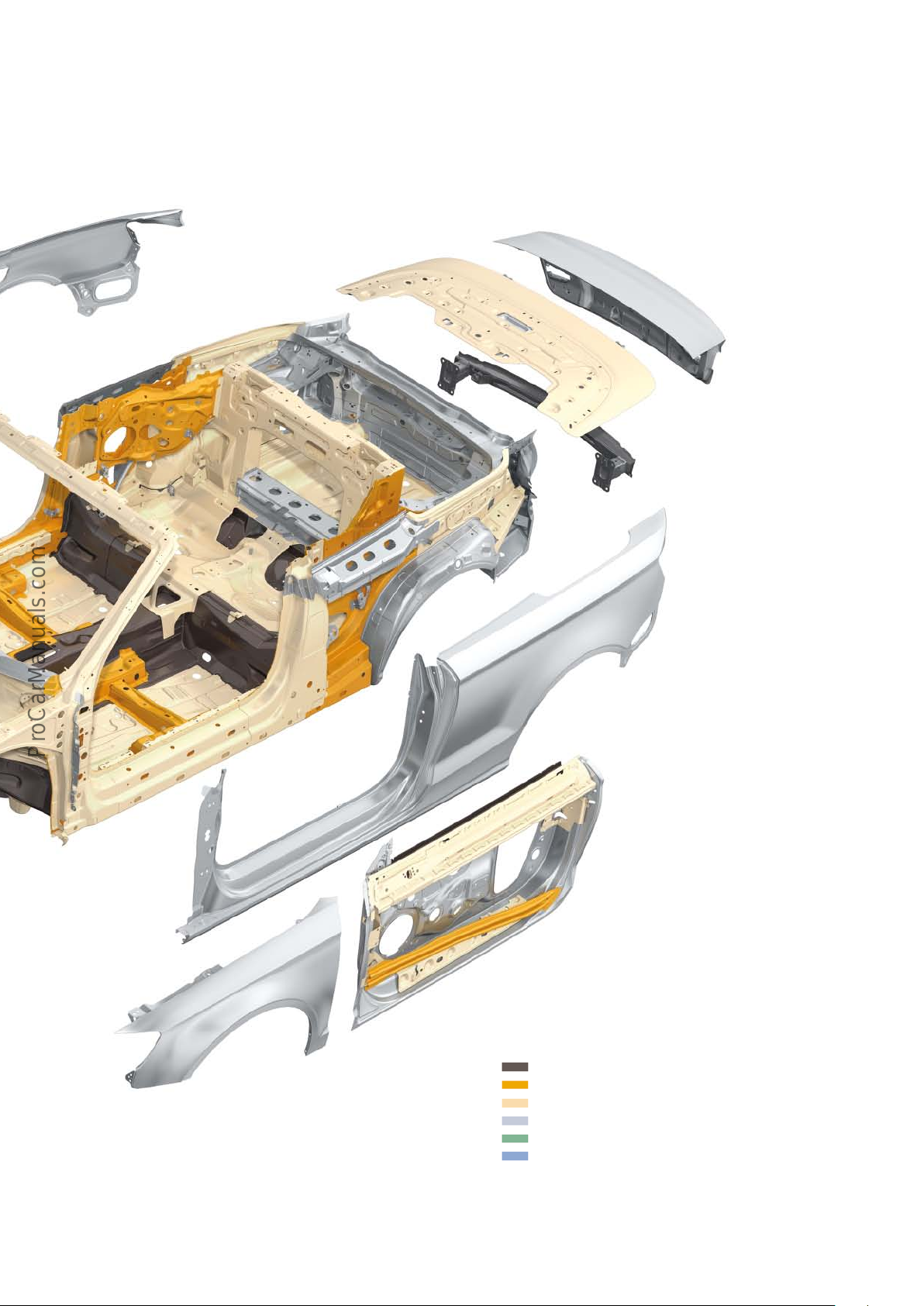
623_106
Key:
Ultrahigh strength steel (hot-formed)
Advanced high strength steel
High strength steel
Low strength steel
Sheet aluminium
Aluminium section
7
Page 8
Body structure/reinforcements
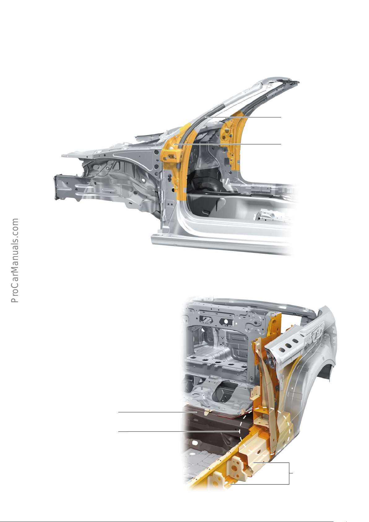
A post reinforcement
The A3 Cabriolet ’14 aords a high level of safety in the event of a
rollover accident thanks to its extremely sti A post structure,
which comprises an inner plate and a reinforcement tube.
The inner plate is made from modern high-tensile steel and the
reinforcement tube from ultra-high-strength thermoformed steel.
Reinforcing tube
Inner A post
Lower rail / sill / seat cross-member reinforcements
Various additional reinforcements are used to ensure that the body
structure meets the high convertible-specific strength requirements in the lower rail/sill and the B post areas. To provide better
side impact protection, the seat cross-member located between
both B posts is made from ultra-high-strength thermoformed
steel.
Seat cross-member
B post with
reinforcements
623_107
Reinforcement
Side member/sill
623_108
8
Page 9
Rear bulkhead
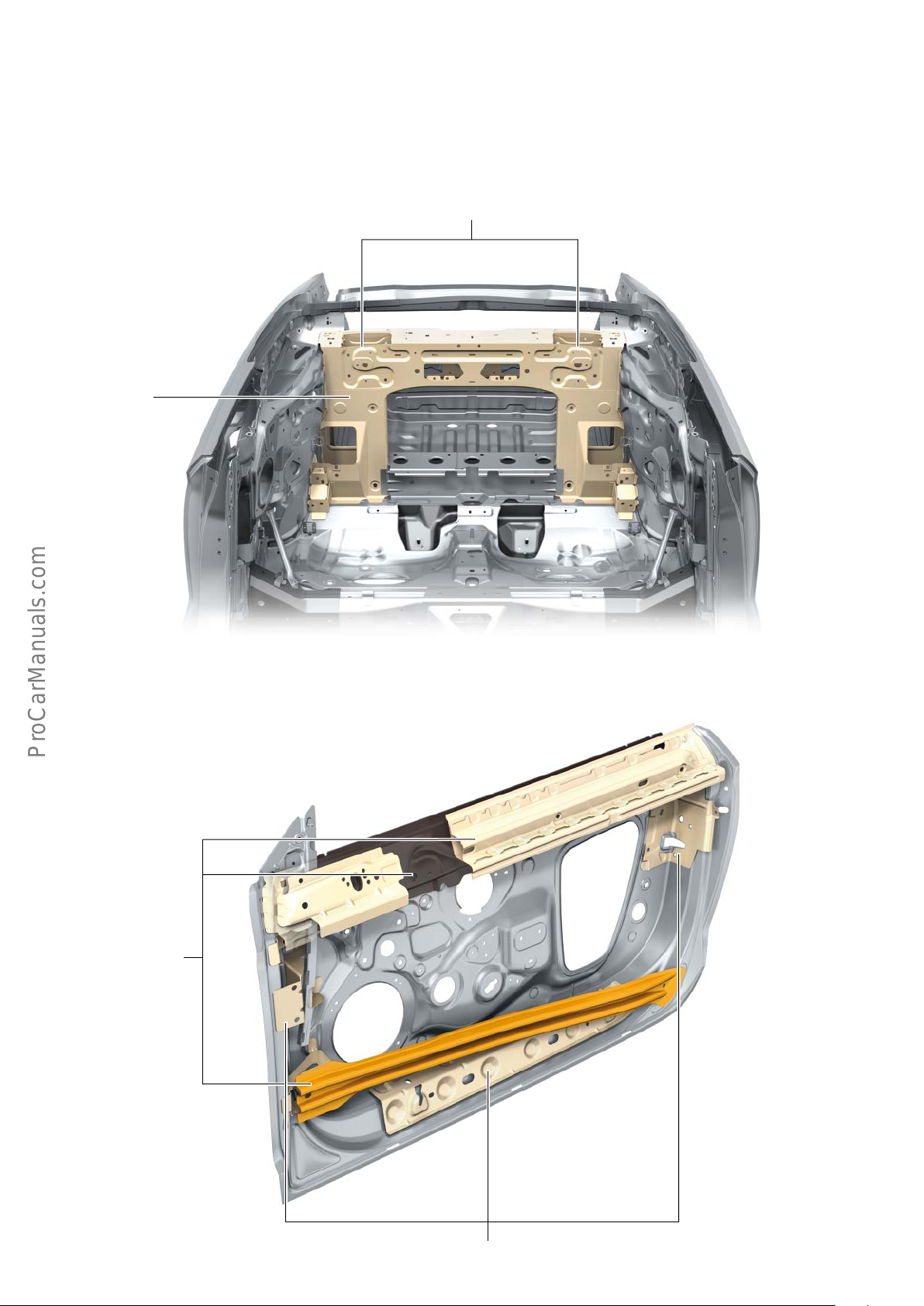
Additional strengthening is provided by the rear bulkhead, which is
rigidly connected to the car body.
High-strength sheet steel is used to achieve extremely high
rigidity in crash-relevant areas, such as the rollover protection
system mounting.
Rollover protection system mounting
Rear bulkhead
This not only provides better safety for the car occupants; it also
increases the stiness of the occupant cell significantly.
Door side impact reinforcement
The door side impact protection is specially adapted for the A3
Cabriolet ’14; during a collision ,it absorbs the impact energy and
dissipates it to the body side structure.
Side impact protection
623_109
623_110
Additional reinforcements
9
Page 10
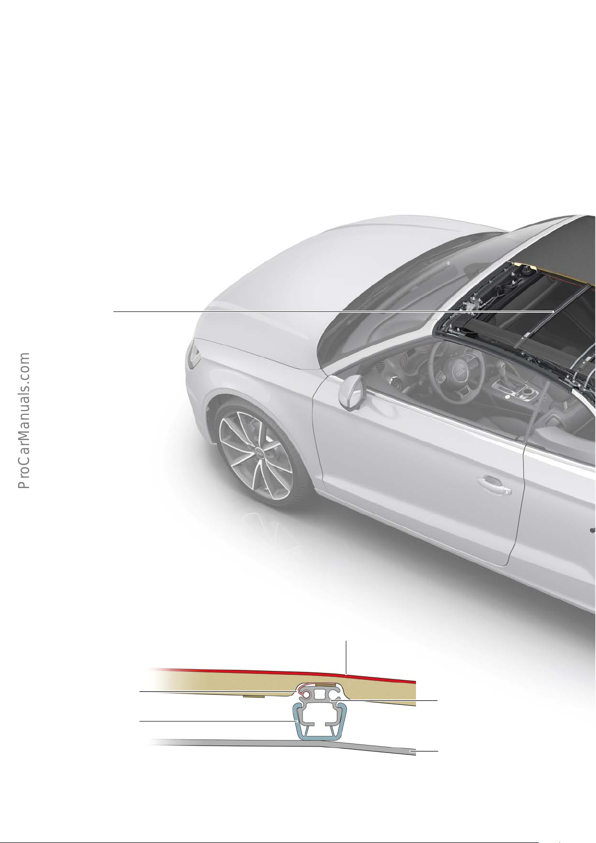
Convertible top
As with the outgoing generation, the new Audi A3 Cabriolet ’14
features a classical soft top with k fold system. The substructure
comprises a mix of magnesium, aluminium and steel. At the press
of a button, the top opens or closes electro-hydraulically in less
than 18 seconds, even while driving up to 50 kph. In the opened
state, the convertible top – folded into three layers – is stowed in a
well.
Roof bow
Excellent thermal insulation and a heated glass rear window mean
the new Audi A3 Cabriolet ’14 is also suitable for winter use. The
soft top is made from rugged materials and optionally available in
a deluxe version (acoustic convertible top).
The complete convertible top weighs approximately 51 kg.
Roof bow
The roof bows contain grooves in which the convertible top
cover is attached by welting. For removal and installation, the
convertible top cover can be pulled in and out at the sides. The
headliner clips onto the roof bows.
Convertible top
cover welting
Headliner retaining strip
Convertible top cover with
sound insulating foam
Roof bow
Interior lining
623_111
10
Page 11
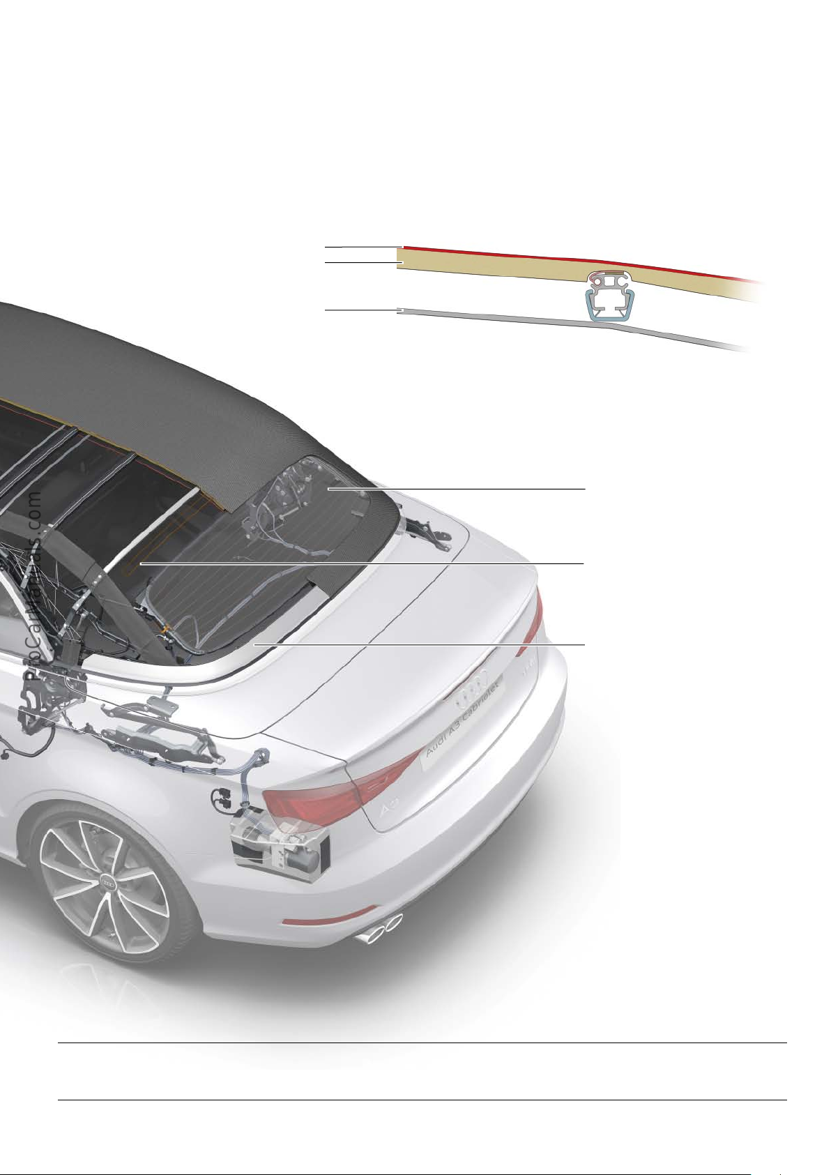
!
Convertible top fabric
The convertible top cover comprises a tarpaulin with layers of
insulation (acoustic insulating foam). The acoustic convertible top
provides superior sound and thermal insulation thanks to an
acoustic insulating foam of adapted density and thickness (10mm
instead of 7 mm in the basic convertible top).
Convertible top tarpaulin
Sound insulating foam
Interior lining
The convertible top tarpaulin itself has a three-layered structure.
The outer layer is made of an acrylic nitrile fabric, the middle layer
of butyl rubber (acoustic convertible top) or chloroprene rubber
(basic convertible top) and the inner layer of polyester fabric. The
tarpaulin is manufactured from a middle panel and two side
sections.
623_112
Rear window
The glass rear window is made of 3.15
mm toughened safety glass and is
electrically heated. It is bonded to the
convertible top cover.
AM aerial
Tensioning strut
The tensioning strut is seated on the convertible top box lid and locks in the OTDC
position so that the hydraulic system can
depressurise after closing.
2
623_113
Note
The integrated glass rear window cannot be replaced individually.
11
Page 12
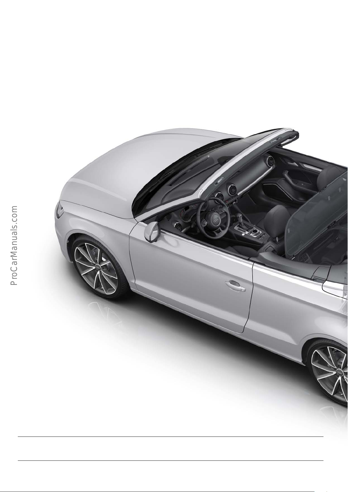
!
Variable convertible top well
The convertible top of the A3 Cabriolet ’14 can only be opened
when the convertible top tray is in the lowered position. The
convertible top well can be lowered manually by pulling the
handle.
The variable convertible top well can be raised when the convertible top is closed, thereby providing additional load capacity in the
boot.
Windbreak
The windbreak reduces draughts inside the vehicle for greater
comfort when driving with the soft top open.
The windbreak is engaged into the side trims behind the front
seats and then moved into the upright position.
When not in use, the windbreak is folded away and stowed in a
storage bag in the boot.
Note
The windbreak can be left on the car when the convertible top is closed.
12
Page 13
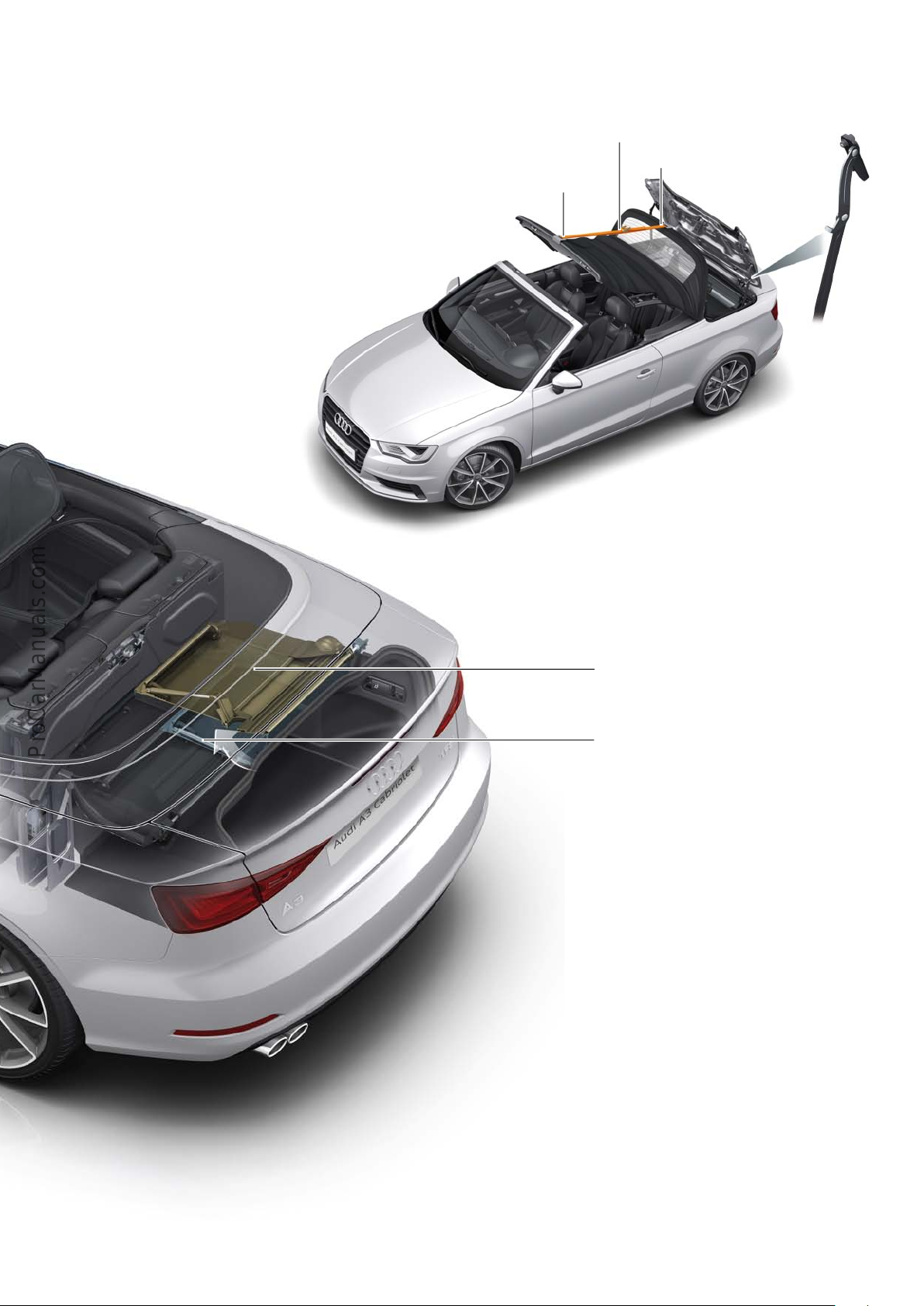
Convertible top box lid/service position
The convertible top box lid is a lightweight steel construction and
stops the open convertible top from becoming dirty. It is opened
and closed by two hydraulic cylinders seated on the left and right
toggle levers (hinges).
For assembly work on the convertible top, the convertible top and/
or the convertible top box lid must be moved into the service
position (limit position). To prevent unwanted closing of the lid,
both toggle levers (hinges) must be pushed towards the tensioning
strut at the upper pivot point as far as the stop.
A tensioning strap (T10038) and two hooks (T4036) are engaged
into the convertible top edge centrally at the front and back and
hold the convertible top in the assembly position.
T 10038
T 40306
T 40306
623_114
Convertible top well, upper position
Convertible top, lower position
623_115
13
Page 14
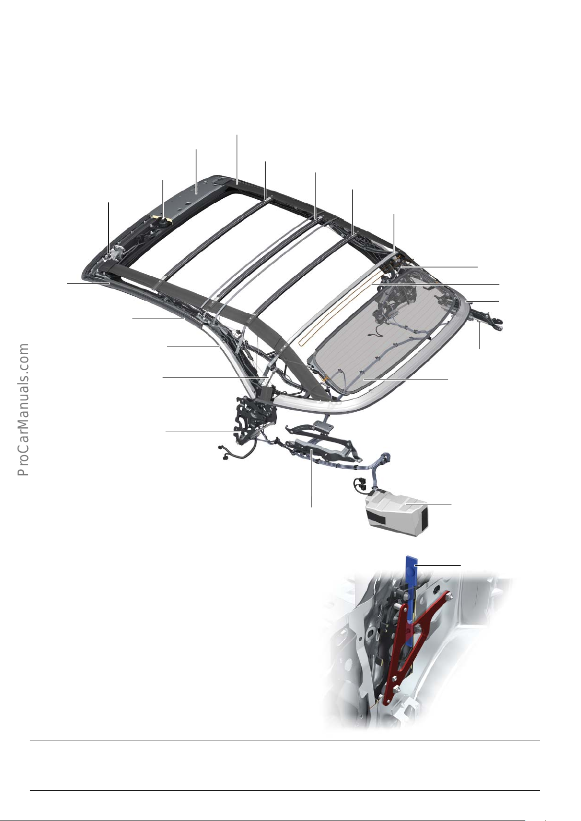
!
Convertible top frame
The convertible top frame to bolted to the car body, with a main
bearing attached to a mounting plate on the left and right.
Unlike in the outgoing model generation, the position of the
retaining plates is now defined by the reference point system (RPS)
of the car body and cannot be changed.
Roof bow tensioning strap
Front roof bow
Roof bow 1
Convertible top
locking motor
Convertible top lock
Front roof
rod
Rear roof rod
Roof bows 1-4 are made from extruded aluminium sections. The
front roof bow, on the other hand, is made from high-grade magnesium on account of its complex design. By using these dierent
materials, the convertible top frame meets high standards for
stability and strength.
Roof bow 2
Roof bow 3
Roof bow 4
Hydraulic cylinder
for tensioning strut
AM aerial
Tensioning strut
2
Main side bar
Hydraulic cylinder
for tensioning strut
Main bearing with
hydraulic cylinder for
convertible top
Main bearing
The convertible top can be removed and installed using the two
spacers T40307, which are inserted into the left and right main
bearings from above and remain inside the main bearings during
the entire time the convertible top is removed.
When the convertible top is removed, the spacers replace the
missing stop buers on the car body and thereby prevent damage
to the convertible top cover and convertible top frame while the
convertible top is in storage or transit.
Hydraulic cylinder
Convertible top box lid
Rear window
Hydraulic pump
Hydraulic cylinder
Convertible top box lid
623_116
T40307
Note
Please follow the instructions given in the Workshop Manual during all work on the convertible top.
14
Page 15
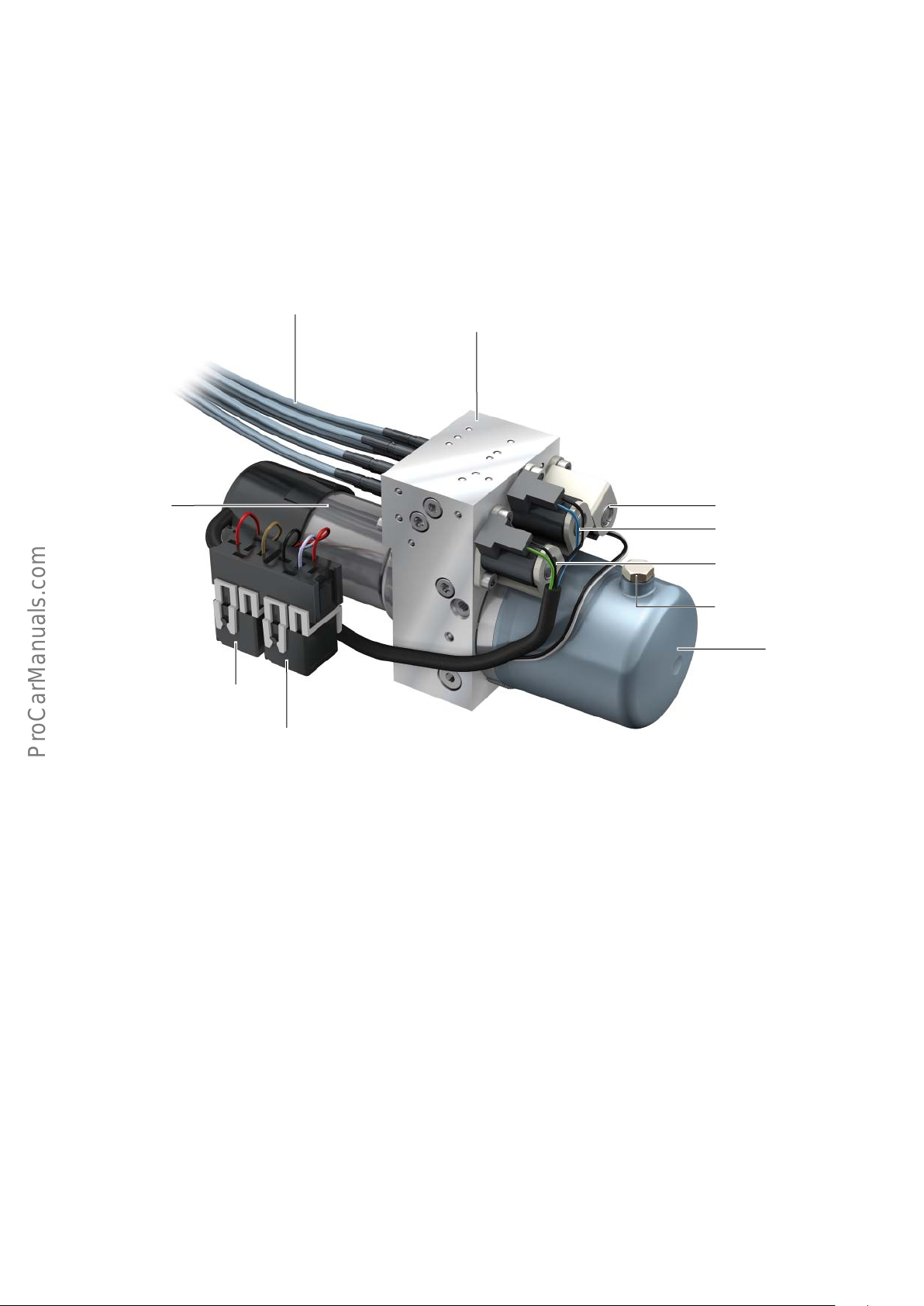
Hydraulic unit
The hydraulic unit consists of the electric motor, the valve block
(including pump and valves) and the oil tank.
Plastic-sheathed flexible metal spiral hoses connect the hydraulic
cylinders to the hydraulic unit. Relays 1 and 2 are clipped onto the
hydraulic unit and control the operating current for clockwise and
anticlockwise operation of the pump.
During the convertible top raising or lowering sequence, the pump
runs and valves 1-3 control the flow of fluid according to the
required sequence of movements.
Plastic-sheathed flexible
metal spiral hose
Electric motor
The direction of rotation of the pump only needs to be reversed to
move the tensioning strut into position when raising the convertible top.
Pump pressure is limited to max. 180 bar by pressure-limiting
valves.
When the system is at rest, the hydraulic fluid can flow back from
the hydraulic cylinders to the fluid reservoir unpressurised, allowing the convertible top to be emergency-operated.
Valve block
Power operated convertible
top valve -2- N341
Power operated convertible
top valve -1- N272
Power operated convertible
top valve -3- N342
Relay 2 J588
Relay 1 J321
Bleeding the system
If repair work has been performed on the hydraulic system, no
bleeding is required. The hydraulic system is bled automatically
during operation.
Hydraulic cylinder
Double-acting hydraulic cylinders are used. They can be activated
from both sides according to the movement sequence and are
birdirectional.
Oil filler screw
Oil reservoir
623_118
Solenoid valve
The hydraulic system is fitted with 3/2-way valves (valves with 3
connections and 2 switch positions) which are operated electromagnetically and reset by spring force. Oil flows out of the cylinders and into the tank when the valves are de-energised, and from
the pump to the cylinders when the valves are energised.
The valves are activated by the control unit for 5 minutes. The
convertible top can be emergency-operated directly after the
valves have been switched o. When the valves are de-energised,
the hydraulic system depressurises and the convertible top collapses completely.
15
Page 16
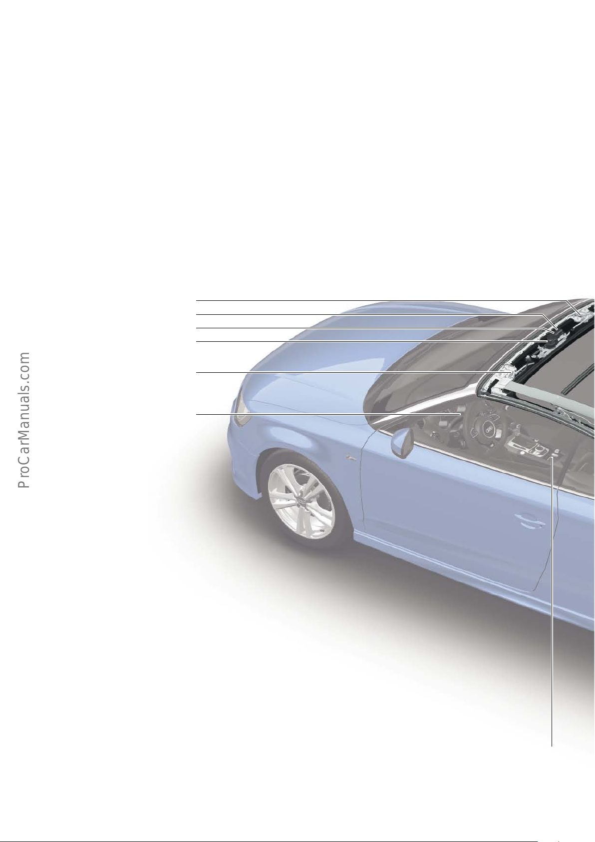
Convertible top control system
Installation locations of the convertible top control unit
The component parts of the system are summarised on the following two pages.
F412
F294
F295
V223
F411
J285
16
F137
Page 17
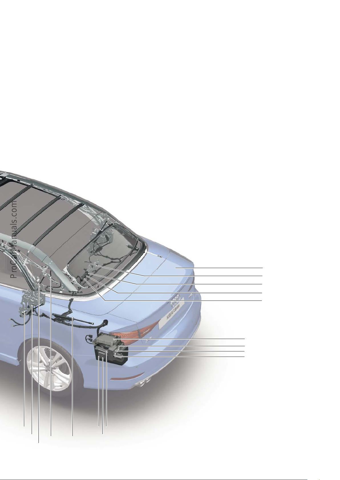
Key
E137 Convertible top operating switch
F171 Convertible top stowed switch
F202 Convertible top front switch
F293 Convertible top box lid latch unlocked switch
F294 Convertible top lock open switch
F295 Convertible top lock closed switch
F404 Convertible top box lid latch engaged switch
F407 Convertible top box lid up switch
F408 Tensioning strut up switch
F411 Convertible top lock closed switch, left
F412 Convertible top lock closed switch, right
F517 Tensioning strut down switch
F519 Convertible top box lid closed switch
F520 Convertible top well down switch
J256 Convertible top operation control unit
J285 Control unit in dash panel insert (diagram showing con-
vertible top status)
J321 Hydraulic pump relay 1, convertible top operation
J588 Hydraulic pump relay 2, convertible top operation
N272 Power operated convertible top valve 1
N341 Power operated convertible top valve 2
N342 Power operated convertible top valve 3
V118 Convertible top operation hydraulic pump
V222 Convertible top box lid latch motor
V223 Convertible top locking motor
F171
F202
F517
F408
F407
J588
J321
V118
F520
F519
F404
F293
V222
J256
N341
N272
N342
623_023
17
Page 18
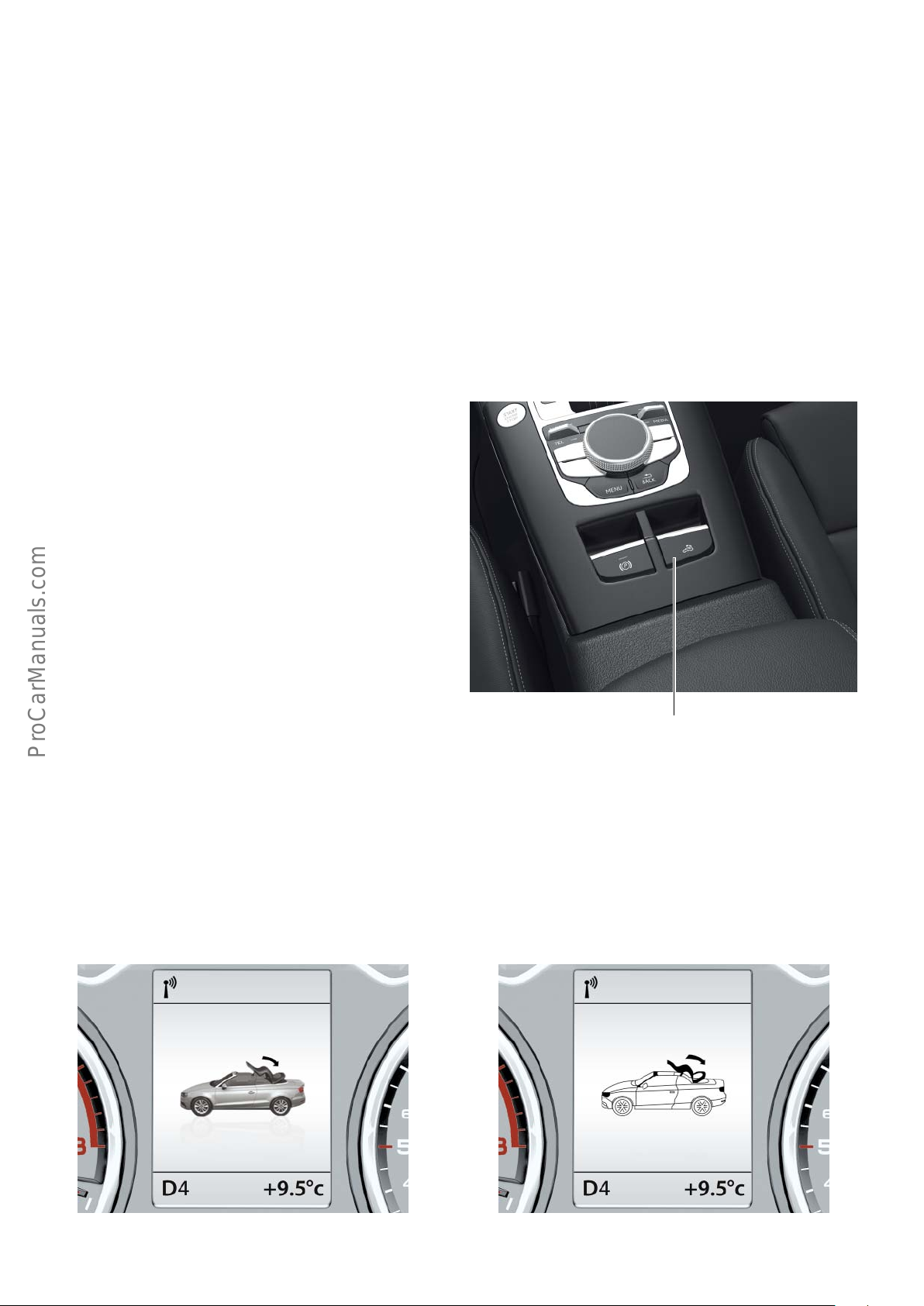
Convertible top operation
The convertible top on the Audi A3 Cabriolet ’14 is opened and
closed by an electro-hydraulic system.
In contrast to the outgoing model, the Audi A3 Cabriolet ’14 has a
convertible top box lid. The convertible top box is completely
covered by the convertible top box lid.
Service position of convertible top and convertible
top box lid
The hydraulic system is depressurised approx. 5 minutes after the
last actuation. The convertible top can then collapse completely
and the convertible top box lid can close. When carrying out work
on the convertible top system, please note that moving parts can
cause injury.
Basics of convertible top operating switch E137
The convertible top opening cycle is started by pulling the convertible top operating switch E137. To open the convertible top completely, the switch must be kept pulled until the opening cycle is
complete. When the switch is released, the convertible top cycle
stops instantaneously. If the switch is pulled again, the convertible
top continues to open. If the switch is pressed, the convertible top
closes.
The switch must also be kept actuated (pressed) during the closing
cycle.
If the convertible top is closed and the switch for opening the
convertible top is pulled and then released again, the side windows
will lower to a certain level. The convertible top cycle will not start.
If the button is now kept pressed for the next 5 seconds, the side
windows closes again.
this function is unavailable due to legal restrictions in some countries, including the USA.
Objects deposited on the convertible top box lid or in the convertible top box can damage the vehicle during convertible top operation. The convertible top is only available as a fully automatic
convertible top. It is also optionally available as an acoustic convertible top. The acoustic convertible top oers better thermal and
sound insulation than the standard convertible top.
This is why the hydraulic pressure must be relieved and the convertible top moved into the service position before carrying out
work on the convertible top. For further information, refer to page
13 "Convertible top box lid/service position" and the Workshop
Manual.
Graphic displays for convertible top operation in instrument panel J285
The Audi A3 Cabriolet ’14 uses a dierent method to indicate
convertible top operation. A separate convertible top operation
warning lamp is no longer used. Instead, the operation of the
As soon as the convertible top starts to open or close, a graphic
display appears in the dash panel insert J285 showing the vehicle
together with the convertible top.
convertible top is now indicated graphically. The displays are
monochrome or colour depending on dash panel insert version.
A curved arrow over the convertible top indicates the direction of
the convertible top. If the arrow tip is pointing back, the convertible top is opening. If the arrow tip is pointing forward, the convertible top is closing.
623_024
Convertible top operating switch E137
Convertible top opening cycle
18
623_025
Convertible top opening cycle
623_026
Page 19
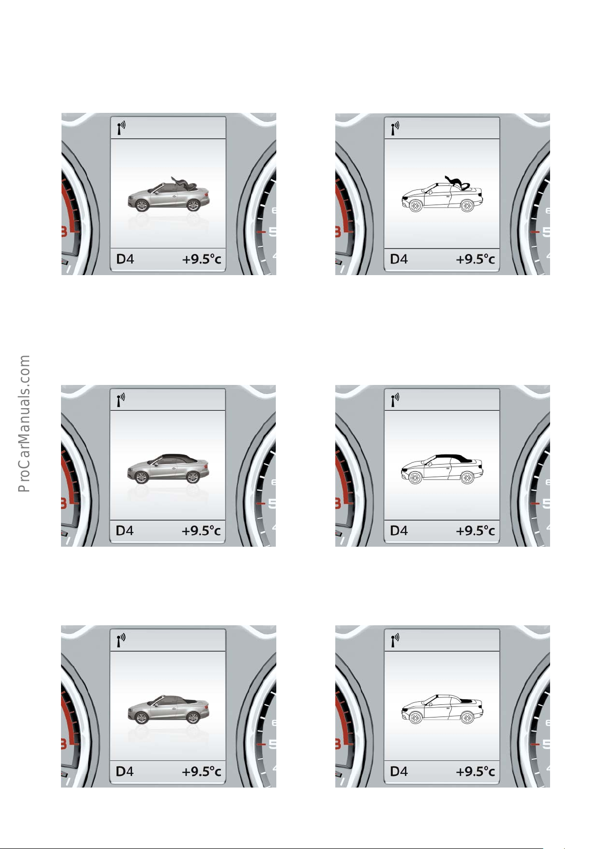
If no arrow is displayed over the convertible top, the convertible
top cycle has been initiated but aborted. The convertible top is
therefore currently in an intermediate position.
Convertible top cycle aborted, intermediate position Convertible top cycle aborted, intermediate position
623_027
If the convertible top cycle has been completed, the status of the
convertible top (opened or closed) is indicated for approx. 2
seconds. An audible signal sounds at the same time.
Convertible top cycle completed, convertible
top closed
623_029
Convertible top cycle completed, convertible
top closed
623_028
623_030
Convertible top cycle completed, convertible
top open
623_051
Convertible top cycle completed, convertible
top open
623_052
19
Page 20
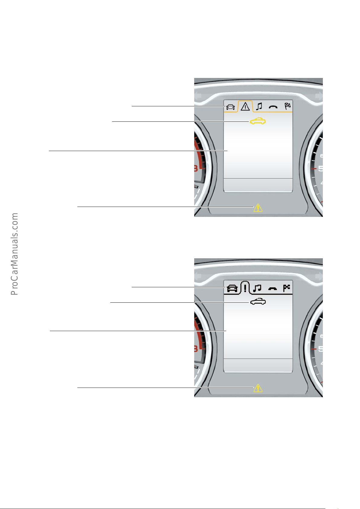
If a convertible top operation is not possible, this is indicated
audibly and visually in the dash panel insert.
A warning is given and nine messages are displayed.
The warning is given if the convertible top is in an intermediate
position, and if the event memory contains an entry and the
vehicle is travelling faster than 5 kph.
Warnings are indicated via the colour dash panel insert as follows:
Triangle with exclamation mark in the driver information
and warning lamps tab
Yellow vehicle-with-convertible-top icon in the
status line
Displayed text
Convertible top:
malfunction!
you can continue driving
(limited functionality).
See owner's manual
Yellow central warning lamp
Warnings are indicated via the monochrome dash panel insert as follows:
Exclamation mark in driver information tab and warning
lamps tab
Vehicle convertible top icon in the status line
Displayed text
623_031
Convertible top:
malfunction!
you can continue driving
(limited functionality).
See owner's manual
Yellow central warning lamp
20
623_032
Page 21
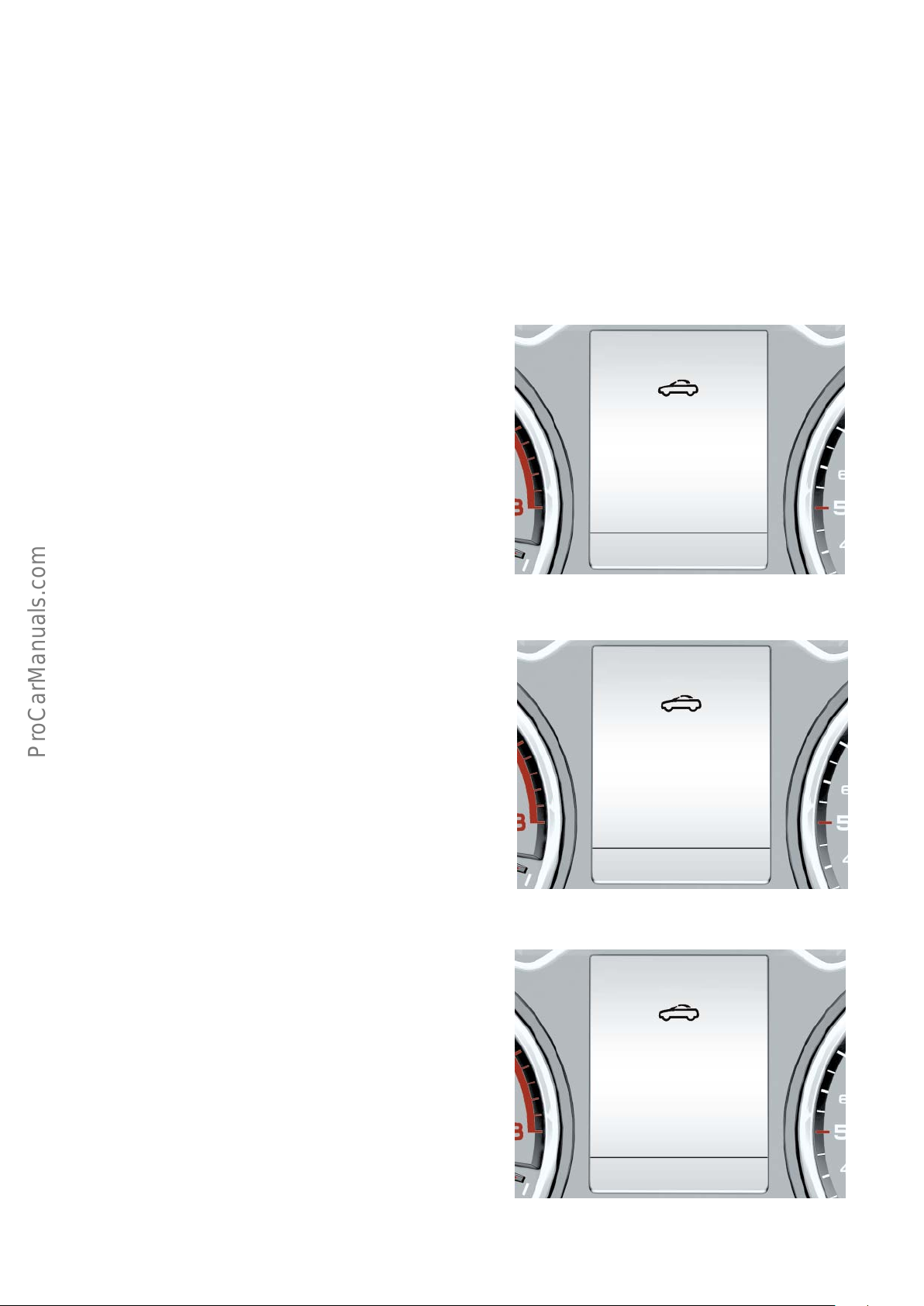
Other reasons why a convertible top operation is not possible are
displayed as messages.
Display of messages in the dash panel insert:
• The yellow warning lamp is NOT activated when messages are displayed.
• Messages are indicated by a white vehicle-with-convertible-top icon in the status line in both the colour and monochrome dash panel
inserts.
• Message texts are NOT included in the driver information and warning lamps tab.
If the convertible top is in a limit position (open or closed) and a convertible top cycle is initiated in the limit stop direction, no actions are
initiated and no messages are displayed.
To activate messages, the following conditions must be met:
The boot lid is open and the convertible top operating switch is
actuated.
Convertible top:
Please close
boot lid
The convertible top well is in the upper position and the convertible top operating switch is actuated in the "open" direction.
The convertible top is in a limit position (open or closed), the
vehicle is travelling faster than 50 kph and the convertible top
operating switch is actuated.
623_033
Convertible top:
Please
lower convertible
top well
623_034
Convertible top:
no operation
possible.
Speed
too high
623_035
21
Page 22
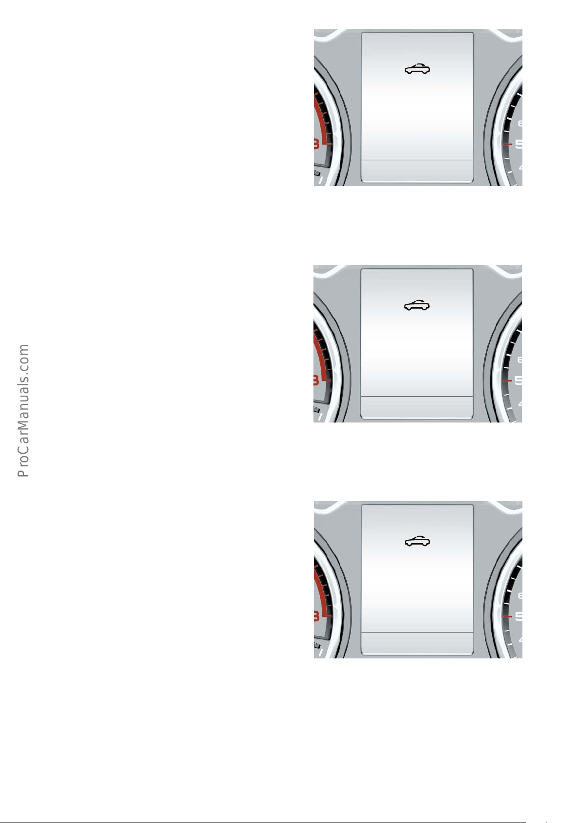
A convertible top cycle is currently active and the vehicle's speed
increases to over 50 kph
or
the convertible top is in an intermediate position and the vehicle's
speed exceeds 50 kph
The ambient temperature is below -15 °C, the convertible top is
closed and the convertible top operating switch is actuated in the
"open" direction.
An open convertible top can also be closed at temperatures below
-15°C.
Convertible top:
not in limit position.
Speed
too high
623_036
Convertible top:
no operation
possible.
Ambient temperature
too low
The convertible top operation control unit has registered a static
event and the switch is actuated.
623_037
Convertible top:
no operation
possible
623_038
22
Page 23
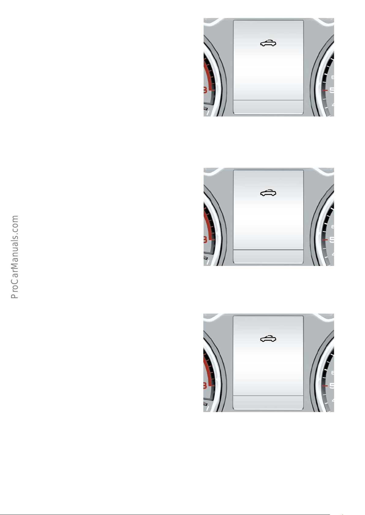
The car’s battery voltage has dropped below a certain value. The
ignition is "on" but the engine is "o" and the convertible top
operating switch is actuated.
The overload protection is active and the convertible top operating
switch is actuated.
Convertible top:
no operation possible.
Engine must be running
623_039
The convertible top operation control unit has registered a static
event, the limit position (open or closed) has been reached and the
actuated convertible top operating switch is released.
Convertible top:
no operation
possible
623_040
Convertible top:
malfunction!
You can continue driving
623_041
23
Page 24
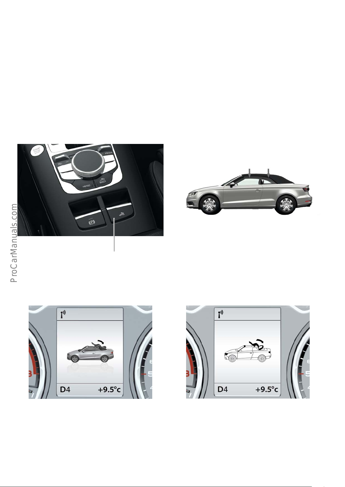
Convertible top opening sequence
To be able to open the convertible top, the following conditions
must be met:
• The vehicle must not be travelling faster than 50 kph
• The function must be switched on
• The ambient temperature must be above -15 °C
Initial situation: the convertible top is closed
Assuming that all conditions are met and the convertible top
operating switch E137 is kept pulled, the side windows initially
open to a certain level.
• The convertible top well must be in the lower position
• The boot lid must be closed
• The battery voltage must be sucient
623_043
623_042
Convertible top operating switch E137
A graphic display then appears in the dash panel insert J285
showing the vehicle with convertible top and a curved arrow. The
arrow tip is pointing back.
Convertible top opening cycle Convertible top opening cycle
623_044 623_045
At this time the boot lid handle release button E234 is not functional.
Therefore, the boot lid cannot be opened.
24
If the rear window heater is on, it is switched o. The rear window
heater can only be switched on if the convertible top is fully closed.
Page 25
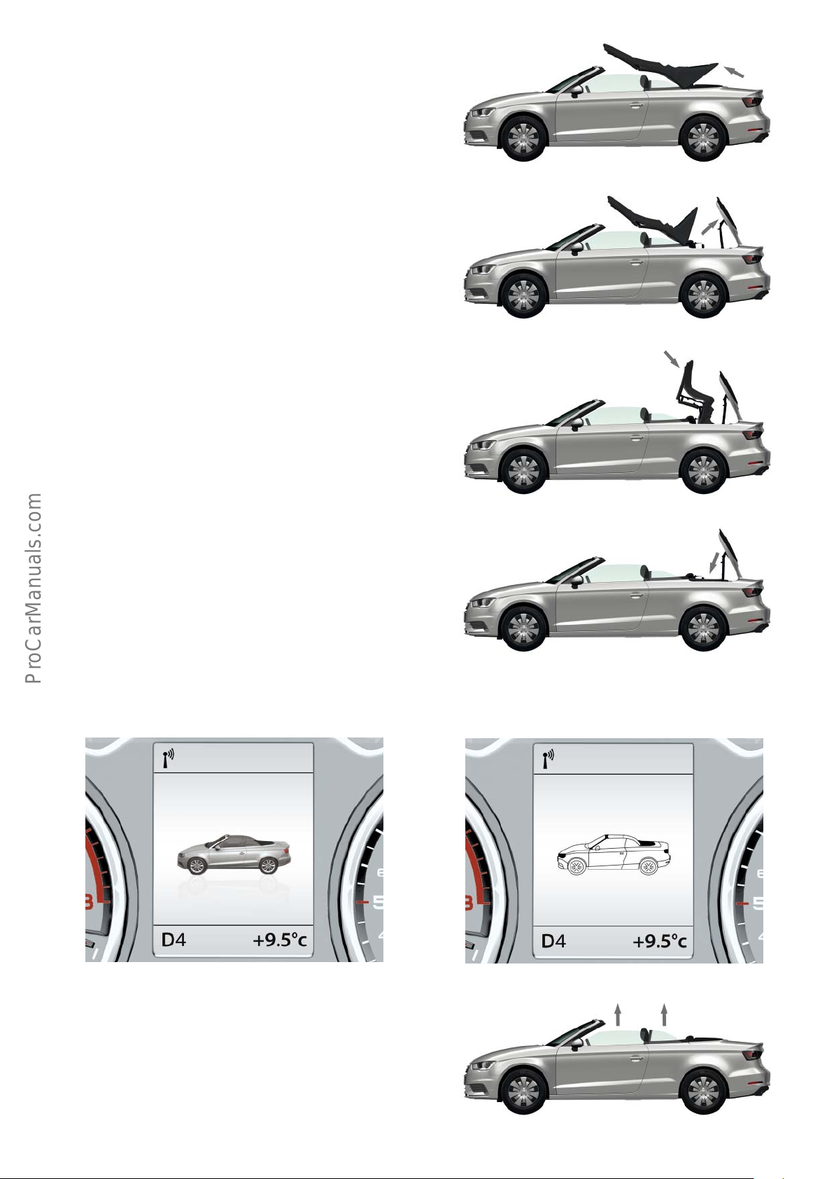
Next, the catch hooks in the upper part of the lock in the window
frame area move upwards. At the same time, the tensioning strut
begins to move into the upright position.
At the same time, the convertible top box lid latch motor V222
opens the convertible top box lid. The tensioning strut moves into
the upright position. The convertible top box lid opens fully.
The convertible top retracts and folds down into the convertible
top well. Meanwhile, the catch hooks close again.
623_046
623_047
623_048
After that, the convertible top box lid closes and the convertible
top box lid latch motor locks the convertible top box lid.
An acoustic signal and a graphic display in the dash panel insert
J285 indicate that the convertible top cycle is complete and the
convertible top is fully open.
Convertible top cycle completed, convertible
top open
623_051
Convertible top cycle completed, convertible
top open
623_049
623_052
Finally, the side windows move up all the way and the boot lid can
again be opened.
623_050
25
Page 26
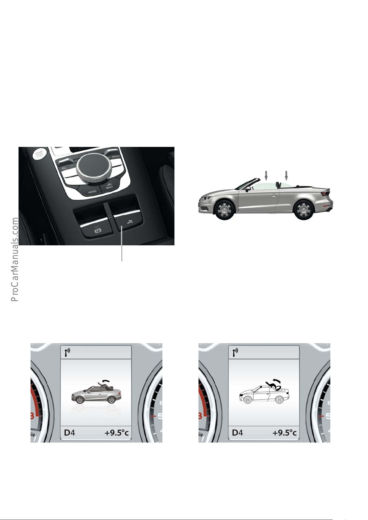
Convertible top closing sequence
To be able to close the convertible top, the following conditions
must be met:
• The vehicle must not be travelling faster than 50 kph
• The function must be switched on
Initial situation: the convertible top is open
The convertible top operating switch E137 is kept pressed. First,
the side windows open to a certain value.
• The boot lid must be closed
• The battery voltage must be sucient
623_046a
623_042
Convertible top operating switch E137
A graphic display then appears in the dash panel insert J285
showing the vehicle with convertible top and a curved arrow. The
arrow tip is pointing forward.
Convertible top closing cycle Convertible top closing cycle
At this time the boot lid handle release button E234 is not functional. Therefore, the boot lid cannot be opened.
26
623_053 623_054
Page 27
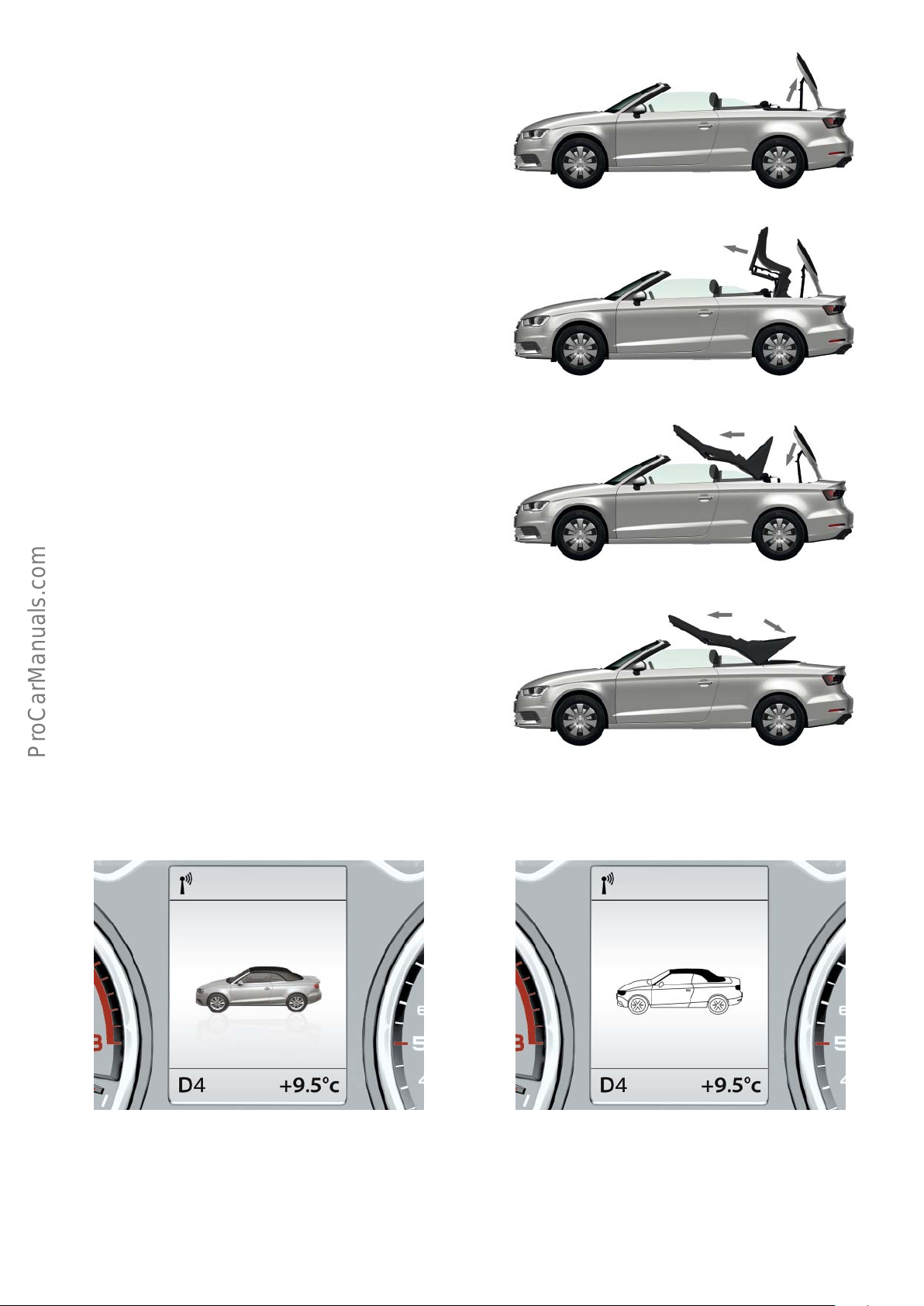
The convertible top box lid latch motor V222 unlocks the convertible top box lid and the convertible top box lid opens fully.
The convertible top lifts up out of the convertible top box and the
catch hooks in the upper part of the convertible top lock open.
The tensioning strut moves into the upper position and the convertible top box lid closes fully. The convertible top box lid latch
motor locks the convertible top box lid.
623_046b
623_046c
The convertible top continues to run until it settles on top of the
window frame. At the same time, the tensioning strut moves
down. The catch hooks then lock the convertible top.
An acoustic signal and the graphic display in the dash panel insert
J285 indicate that the convertible top cycle is complete and the
convertible top is fully closed.
623_046d
623_046e
Convertible top cycle completed, convertible
top closed
623_055
If the convertible top operating switch E137 is kept pressed, the
side windows close. This function is unavailable in some countries
due to legal restrictions.
Convertible top cycle completed, convertible
top closed
623_056
The boot lid can be opened again and the rear window heater can
be switched on again.
27
Page 28
!
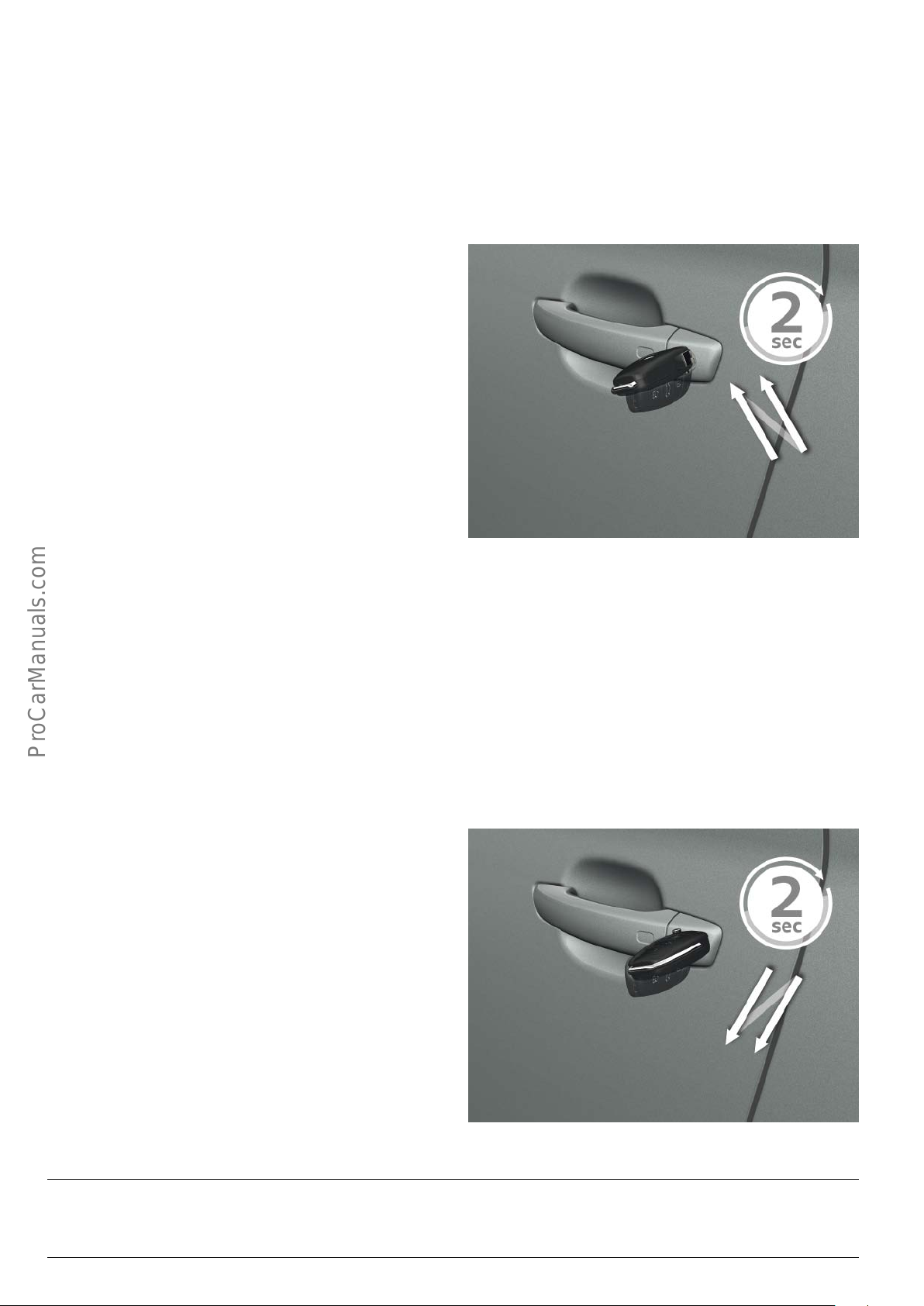
Opening the convertible top with the car key via the lock cylinder on the driver's door.
The convertible top can also be opened using the car key. Before
this can be done, the following conditions must be met:
• The vehicle must be travelling at 0 kph
• The boot lid must be closed
• The battery voltage must be sucient
To open the convertible top, first unlock the vehicle with the car
key. Then insert the car key into the lock cylinder on the driver's
door and turn it in the "open" direction.
If the car key in now turned in the "open" direction again within 2
seconds and held in this position, the convertible top cycle will
start. The car key must be kept held in the "open" position during
the convertible top cycle. When the car key is released, the convertible top cycle will stop instantaneously. To resume the convertible top opening cycle, the car key must again be turned in the
"open" direction and held in this position. If the car key is turned in
the "close" direction and held in this position, the convertible top
will close again.
• The convertible top well must be in the lower position
• The ambient temperature must be above -15 °C
623_057
Closing the convertible top with the car key via the lock cylinder on the driver's door.
The convertible top can also be closed using the car key. Before this
can be done, the following conditions must be met:
• The vehicle must be travelling at 0 kph
• The boot lid must be closed
• The battery voltage must be sucient
Insert the car key into the lock cylinder on the driver's door and
turn it in the "close" direction. If the car key in now turned in the
"close" direction again within 2 seconds and held in this position,
the convertible top cycle will start. The car key must be kept held in
the "close" position during the convertible top cycle. When the car
key is released, the convertible top cycle will stop instantaneously.
To resume the convertible top cycle, the car key must again be
turned in the "close" direction and held in this position. If the car
key is turned in the "open" direction and held in this position, the
convertible top will open again.
623_058
Note
If the convertible top is actuated via the car key, the convertible top will start after a delay.
28
Page 29
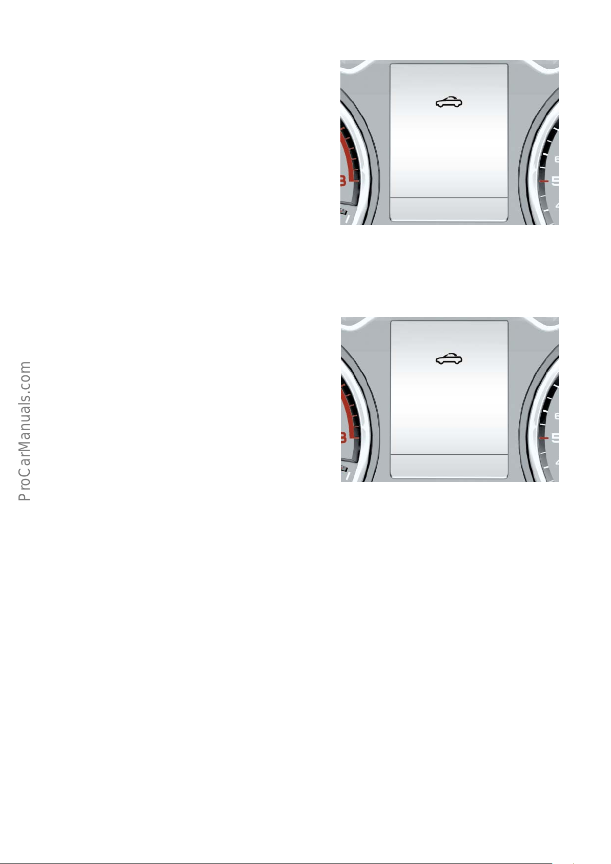
Operating the convertible top while driving
The convertible top can be opened or closed using the
convertible top operating switch E137 up to a speed of 50 kph.
If the vehicle's speed increases to over 50 kph during the convertible top cycle, the driver will be alerted audibly and visually. The
convertible top cycle is stopped and the convertible top comes to a
standstill in its current position. The convertible top cycle cannot
be resumed until the vehcile's speed has dropped to 50 kph or less.
To do this, the convertible top operating switch must be kept
pressed.
Convertible top:
not in limit position.
Speed
too high
A convertible top cycle cannot be initiated if the vehicle is travelling at a speed of over 50 kph. In this case too, the driver is alerted
by audible and visual warnings.
Message text
Message text
623_059
Convertible top:
no operation
possible.
Speed
too high
623_060
29
Page 30
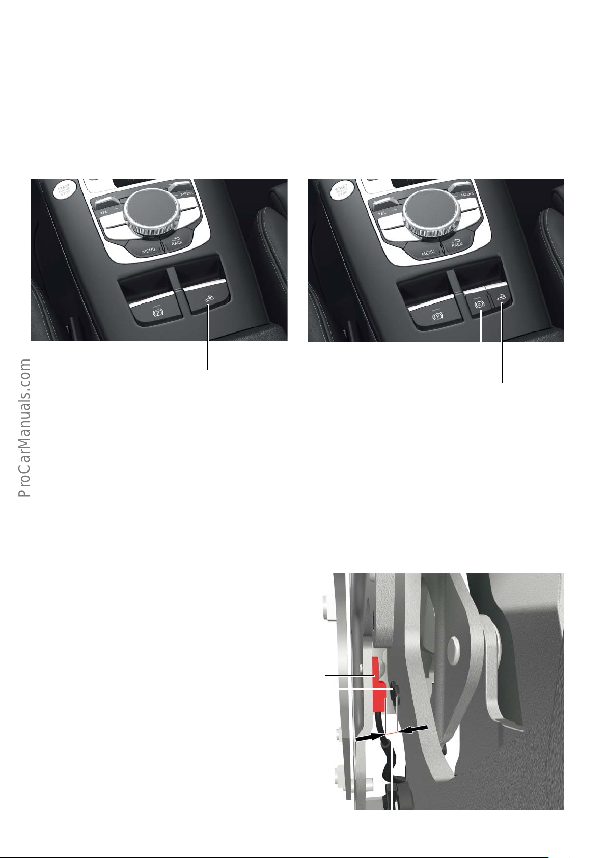
Components of the convertible top control unit
Convertible top operating switch E137
The convertible top operating switch E137 is available in two
versions: firstly in a large version and secondly in a small version.
The small version is installed if the vehicle is equipped with Hill
Start Assist and AUTO HOLD button E540.
623_061 623_062
Convertible top operating switch E137
In this case, the Hill Start Assist switch is installed in place of the
small convertible top operating switch.
Thr functions of the small and large switches are identical.
The switch is installed in the centre console.
AUTO HOLD button E540
Convertible top operating switch E137
Hall sensor
Controlled operation of the convertible top is only possible if the
convertible top operation control unit J256 receives information
from the sensors and switches during every phase of the convertible top cycle. The sensors and switches indicate the current
position of certain parts of the convertible top system to the
convertible top operation control unit J256. The convertible top
operation control unit J256 uses this information to control the
actuators and, thus, the operation of the convertible top.
The following Hall sensors in the Audi A3 Cabriolet ’14 react to the
fields generated by permanent magnets:
• Convertible top well down switch F520
• Convertible top lock closed switch, left F411
• Convertible top lock closed switch, right F412
• Convertible top box lid closed switch F519
• Convertible top front switch F202
• Convertible top stowed switch F171
• Tensioning strut up switch F408
The aforementioned Hall sensors are referred to as monopolar or
unipolar Hall sensors. They react to the south pole of a permanent
magnet.
Permanent magnet
Hall sensors work on the so-called Hall eect principle According
to the Hall eect, a magnetic field acts perpendicular to the
direction of current flow in a live conductor, resulting in voltage
dierences. These voltage dierences are converted to signals and
utilised by the convertible top operation control unit J256.
The switching distance of the aforementioned Hall sensors can be
in excess of 3 mm.
Hall sensor
30
623_063
Switching distance
Page 31
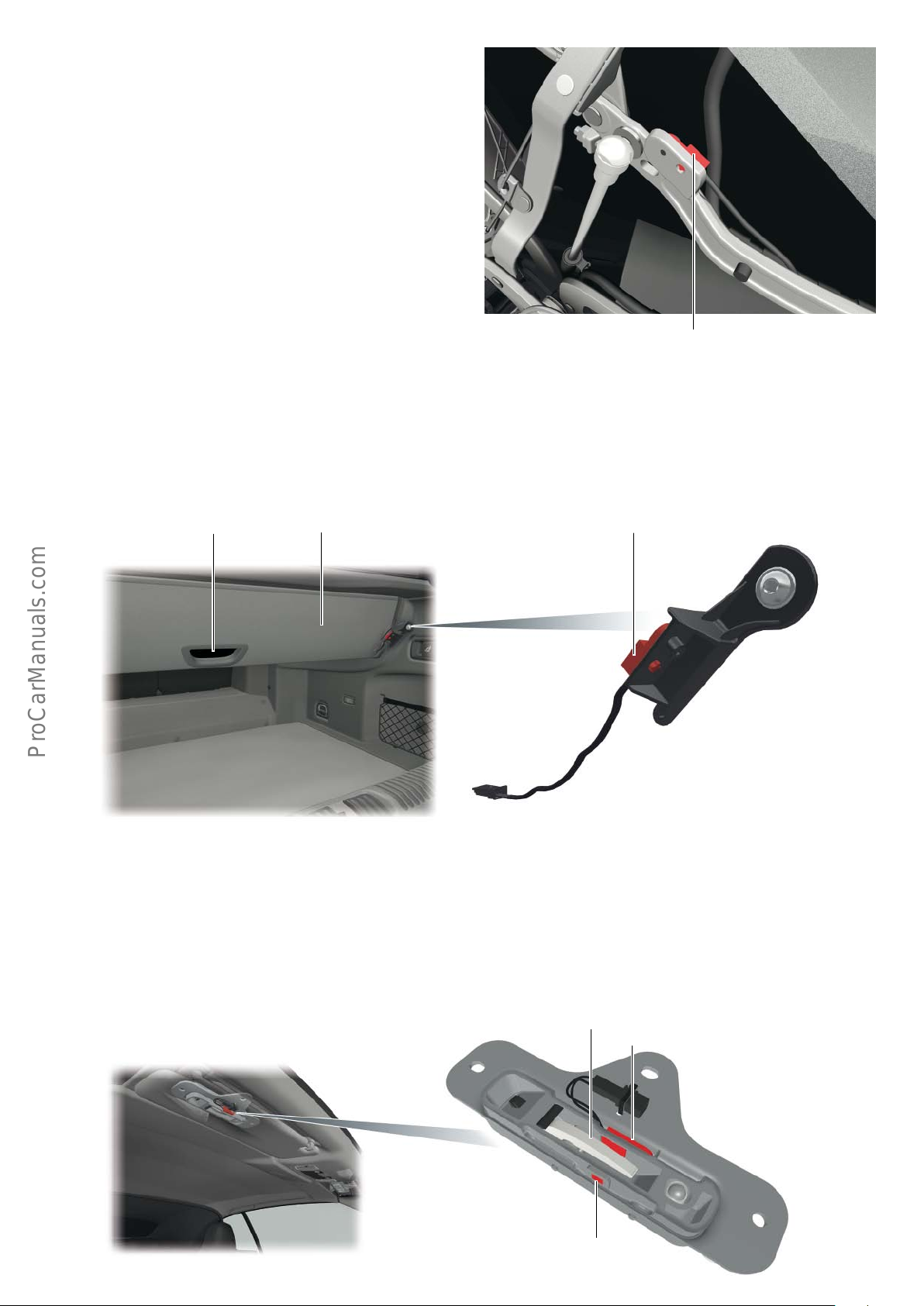
Tensioning strut up switch F408
The tensioning strut up switch F408 is installed on the long tensioning strut pivot arm on the left-hand side as seen in the direction of travel. This switch is a Hall sensor. A permanent magnet is
attached to the joint on the pivot arm.
When the tensioning strut reaches its upper position, the tensioning strut up switch F408 and the permanent magnet are facing one
another. In this position, the convertible top operation control unit
J256 detects "tensioning strut up".
Convertible top well down switch F520
The convertible top well switch F520 is installed on the convertible
top well at the rear right as seen in the direction of travel. This
switch is a Hall sensor which detects when the variable convertible
top well is in the lowered position. The convertible top cannot be
opened when the variable convertible top well is in the upper
position.
Handle
Convertible top well
Tensioning strut up switch F408
623_069
The variable convertible top well has to be actuated manually. It is
lowered by pulling the handle and raised by pushing the handle.
The advantage of the variable convertible top well is that it provides approx. 40 litres of additional load capacity in the boot when
the convertible top is closed and the convertible top well raised.
Convertible top well down switch F520
623_064
Convertible top lock closed switch, left F411 and
convertible top lock closed switch, right F412
The convertible top lock closed switch, left F411 and the convertible top lock closed switch, right F412 are located on the left and
right-hand convertible top latch locks respectively. These switches
are Hall sensors.
623_065
The convertible top locking motor V223 engages and disengages
the catch hooks on the convertible top. When the catch hooks are
engaged in the lock, the switches send a signal which the convertible top operation control unit interprets as "catch hooks engaged
in lock".
Catch hook
Convertible top lock closed switch
Permanent magnet
31
Page 32
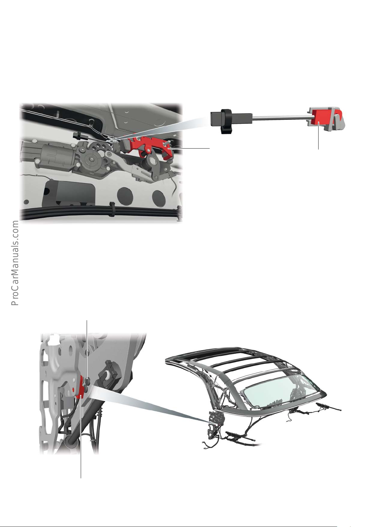
Convertible top box lid closed switch F519
The convertible top box lid closed switch F519 is located on the
convertible top box lid latch motor V222. This switch is a Hall
sensor.
A permanent magnet is attached to the striker. The permanent
magnet is directly facing switch F519 when the convertible top box
lid is closed.
The convertible top operation control unit then detects "convertible top box lid closed".
Striker on convertible
top box lid
Convertible top box lid
closed switch F519
623_066
Convertible top front switch F202
The convertible top front switch F202 is installed in the direction
of the travel, on the stationary part of the main bearing bolted to
the body on the left-hand side of the vehicle. The switch is attached
to the rear main bearing in the direction of travel. This switch is a
Hall sensor.
Permanent magnet
A permanent magnet is attached to the moving part of the main
bearing. If the permanent magnet stops within the detection
range of the switch, convertible top locking control unit detects
"convertible top in front position".
32
623_067
Convertible top front switch F202
Page 33
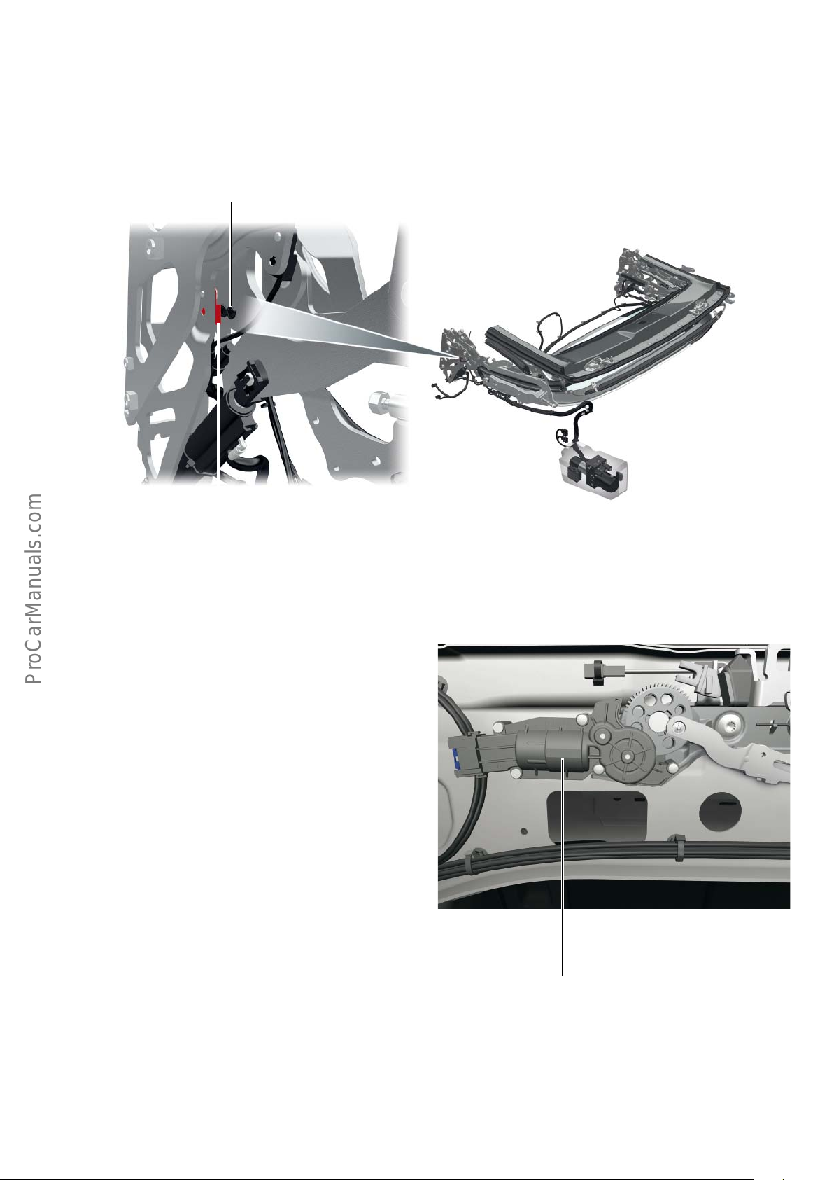
Convertible top stowed switch F171
The convertible top stowed switch F171 is installed in the direction
of the travel, on the stationary part of the main bearing bolted to
the body on the left-hand side of the vehicle. The switch is attached
to the rear main bearing in the direction of travel. This switch is a
Hall sensor.
Permanent magnet
A permanent magnet is attached to the moving part of the main
bearing. If the permanent magnet stops within the detection
range of the switch, convertible top locking control unit detects
"convertible top front".
623_068
Convertible top stowed switch F171
Convertible top box lid latch motor V222
The convertible top box lid latch motor locks the convertible top
box lid. Motor V222 is activated by the convertible top operation
control unit J256. The motor is mounted on the anti-roll bar
cross-member.
623_070
Convertible top box lid latch motor V222
33
Page 34
Convertible top box lid latch unlocked switch F293 and
convertible top box lid latch engaged switch F404
Both switches are integrated in the convertible top box lid latch
motor V222.
The microswitches are actuated by nipples on the toothed
segment.
This switch tells the convertible top operation control unit J256
whether the convertible top box lid latch is engaged or disengaged.
Boot lid
Convertible top box lid latch
engaged switch F293
623_070
Convertible top box lid latch engaged switch F404
The convertible top can only be operated when the boot lid is
closed. When the convertible top cycle is initiated, the onboard
power supply control unit J519 prevents the boot lid from being
opened via the boot lid handle release button E234. On completion of the convertible top cycle, the boot lid handle release button
E234 is re-enabled.
If a convertible top cycle is initiated with the convertible top
operating switch E137, the adjacent diagram in the dash panel
insert indicates that the boot lid is open and, therefore, that the
convertible top cannot be operated.
623_072
Switch for releasing the boot lid
34
Convertible top:
Please close
boot lid
623_073
Page 35
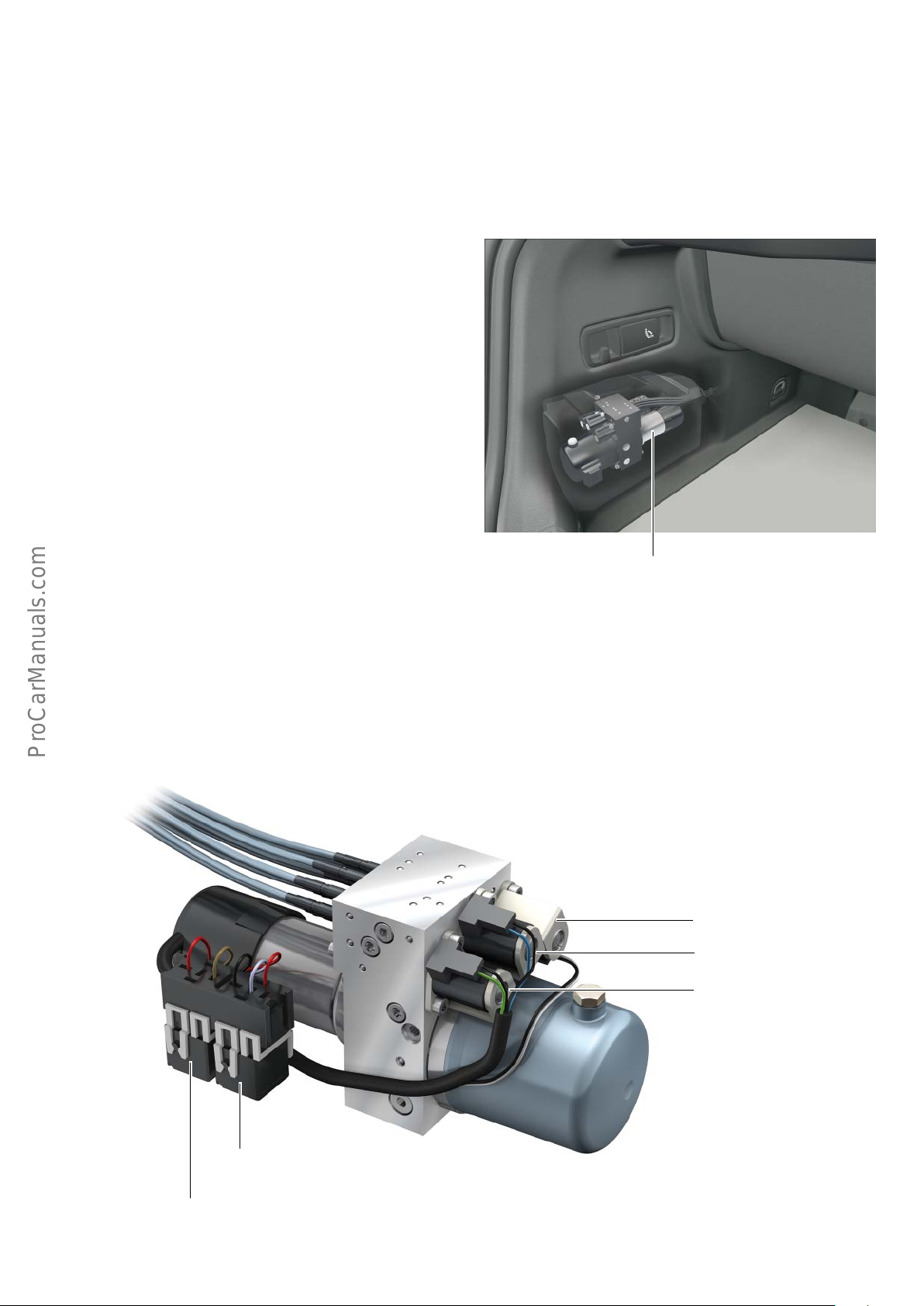
Convertible top operation hydraulic pump V118
Convertible top operation hydraulic pump V118 including
• Hydraulic pump relay, convertible top operation J321
• Hydraulic pump relay 2, convertible top operation J588
• Power operated convertible top valve -1- N272
The hydraulic pump together with the relays and valves form a
unit. The hydraulic pump is installed in the boot, behind the
luggage compartment trim on the left-hand side as seen in the
direction of travel. The hydraulic pump is housed in an acoustic
enclosure which provides sound insulation during pump operation.
• Power operated convertible top valve -2- N341
• Power operated convertible top valve -3- N342
The convertible top operation control unit J256 controls the
hydraulic pump via both relays. The relays control the clockwise
and anticlockwise operation of the pump.
623_074
Convertible top operation hydraulic pump V118
Depending on the deployment direction of convertible top
(opening or closing), the valves guide the oil flow through the hose
system and into the hydraulic cylinders.
Power operated convertible
top valve -2- N341
Power operated convertible
top valve -1- N272
Power operated convertible
top valve -3- N342
Hydraulic pump relay 1,
convertible top operation J321
Hydraulic pump relay 2,
convertible top operation J588
623_118
35
Page 36
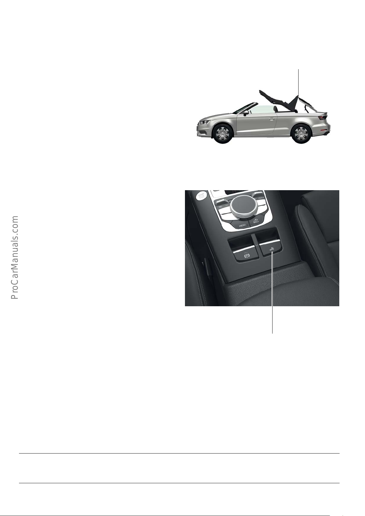
!
The hydraulic system is self-locking. This means that the pressure
generated by the pump is maintained within the system for
approx. 5 minutes. The system de-energises the valves after
approx. 5 minutes, causing the hydraulic system to depressurise.
If the convertible top is in an intermediate position and the
hydraulic system depressurises, the convertible top will collapse
depending on its position. Also, the convertible top box lid will
close depending on its position. In the worst-case scenario, the
convertible top will collide with the convertible top box lid.
If this happens, the convertible top or the convertible top box lid
may become damaged. It may also be the case that neither the
convertible top box lid nor the convertible top reaches one of its
limit positions. It is no longer possible to operate the convertible
top because, in this case, the convertible top operation control unit
receives implausible signals. The message "Convertible top: no
operation possible" is displayed in the dash panel insert.
To be able to continue operating the convertible top, the convertible top box lid must be moved manually into a limit position.
The convertible top cycle can then be resumed. If the limit position
was reached by opening the convertible top box lid, the convertible
top box lid must be secured to prevent it from slamming shut.
Refer to description on page 43.
Collision of the convertible top and convertible top box lid
623_076
The system can also be depressurised manually by turning o the
ignition and pushing or pulling the convertible top operating
switch E137 for approx. 5 seconds.
623_077
Convertible top operating switch E137
Note
Avoid collisions between the convertible top and the convertible top box lid while the top is lowering.
36
Page 37
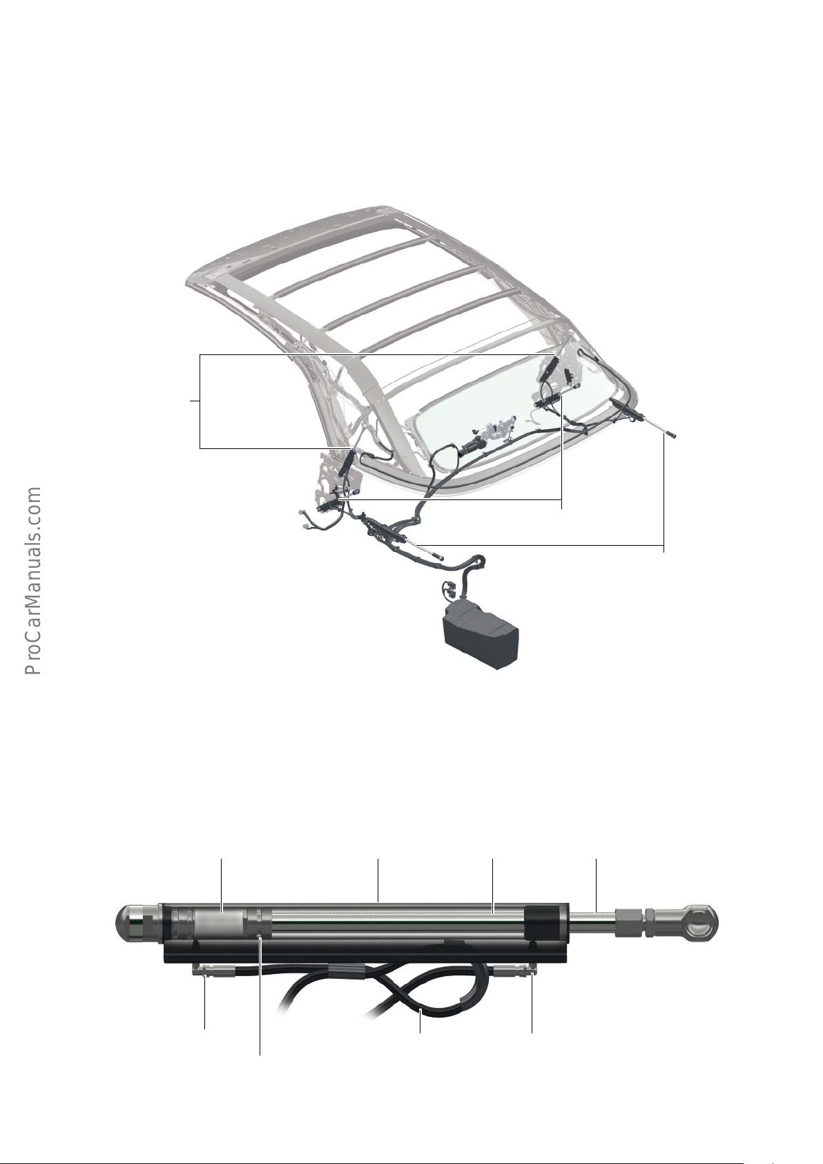
Hydraulic cylinder
The convertible top of the A3 Cabriolet ’14 is equipped with three
hydraulic cylinder pairs. Two cylinders are responsible for actuating
the convertible top box lid, two other cylinders are responsible for
the roof bows, and the last two are responsible for the convertible
top.
Cylinder pair for
tensioning strut
The hydraulic cylinders can be actuated from both sides and
therefore act in two working directions.
Compression stage
Cylinder pair for convertible top
Cylinder pair for
convertible top box
lid
623_078
Hydraulic cylinder Tension stage Piston rod
Hydraulic connection
623_079
Hydraulic line Hydraulic connection
Pistons
37
Page 38
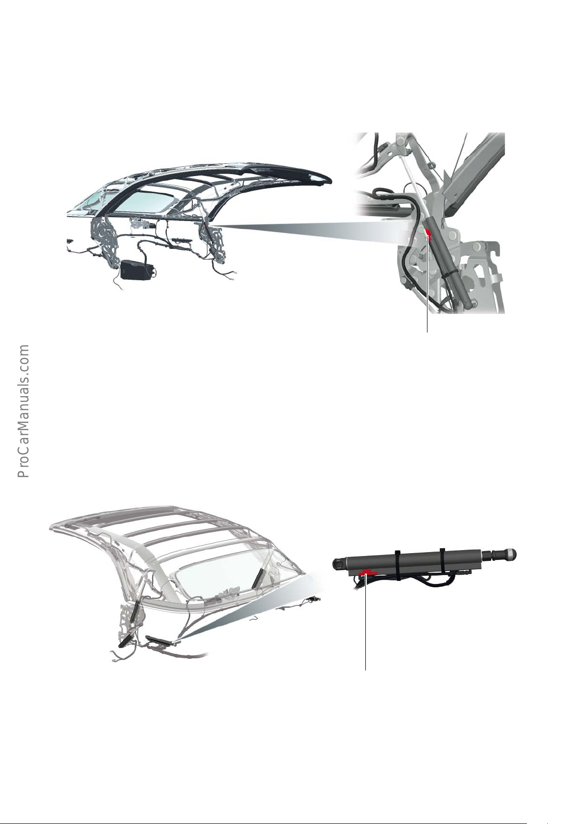
Tensioning strut down switch F517
The tensioning strut down switch F517 is integrated in the hydraulic cylinder responsible for the movement of the tensioning strut,
on the left-hand side of the vehicle as seen in the direction of
travel. This sensor is a Hall sensor, which is attached to the hydraulic cylinder and can be replaced separately.
When the tensioning strut is in its lowest position (tensioned), the
cylinder is fully extended and the Hall sensor sends a signal which
the convertible top operation control unit interprets as "tensioning
strut down".
623_080
Tensioning strut down switch F517
Convertible top box lid up switch F407
The convertible top box lid switch F407 is integrated in the hydraulic cylinder responsible for the movement of the convertible top
box lid, on the left-hand side of the vehicle as seen in the direction
of travel. This switch is a Hall sensor, which is attached to the
hydraulic cylinder and can be replaced separately.
When the convertible top box lid is fully open, the cylinder is fully
retracted and the Hall sensor sends a signal which the convertible
top operation control unit interprets as "convertible top box lid
open".
623_081
38
The convertible top box lid switch
F407 is built into the cylinder
Page 39
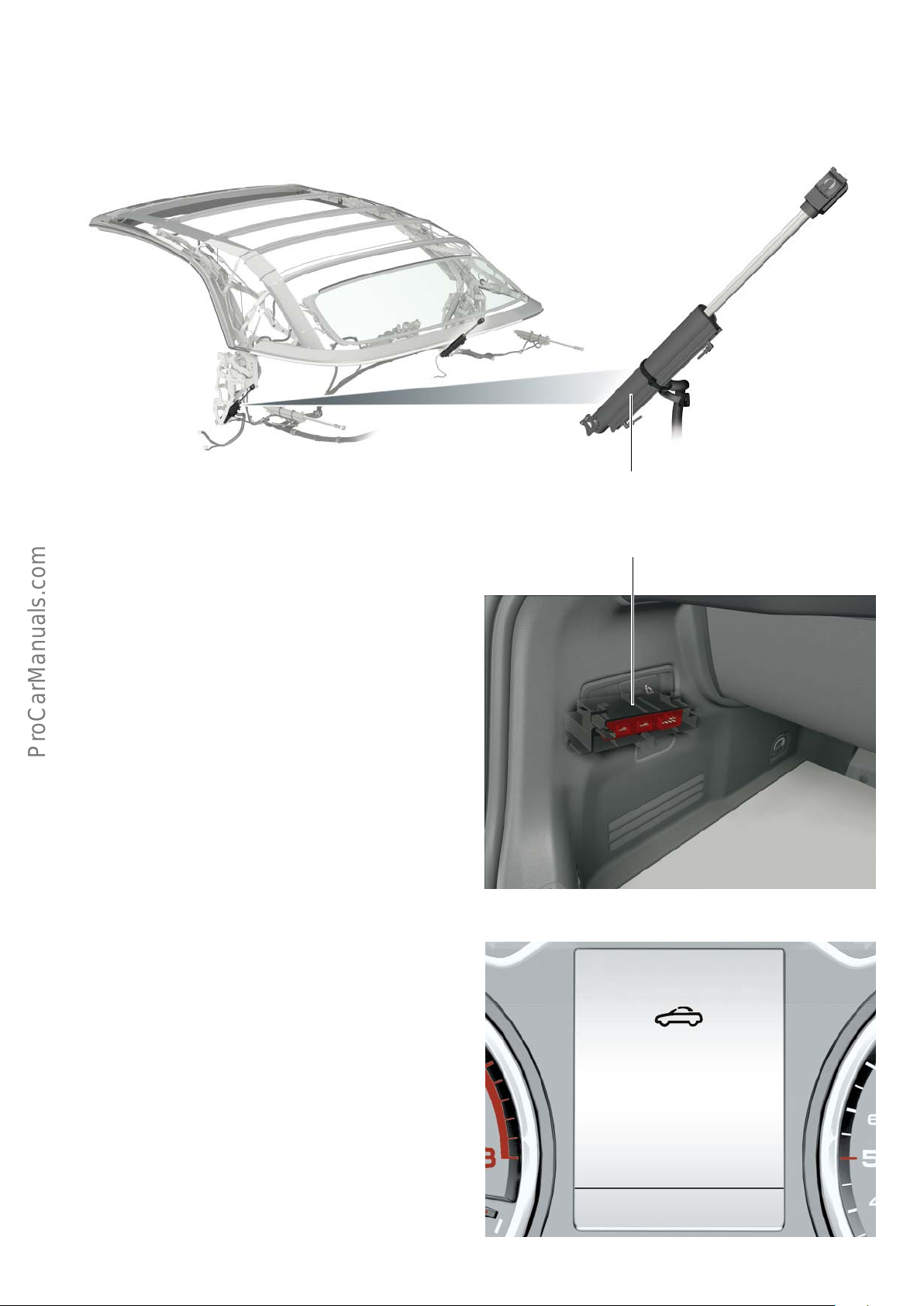
Hydraulic cylinder of main bearing
There are no Hall sensors in the hydraulic cylinders of the main
bearing. The hydraulic cylinders of the main bearing are responsible for the movement of the convertible top.
623_082
Hydraulic cylinder of main bearing
Convertible top control unit J256
The convertible top operation control unit J256 is fitted in a compartment in the boot, behind the trim over the convertible top
operation hydraulic pump V118; this is on the left-hand side of the
vehicle as seen in the direction of travel.
The control unit is integrated in the vehicle's bus system via the
convenience CAN bus and exchanges data with other systems
across this bus. The control unit controls and monitors each individual convertible top operating cycle. It collects the information
generated by the sensors as well as information from other bus
users, evaluates it and controls the actuators accordingly.
The control unit is also responsible for system diagnostics. If
irregularities are detected in the system or if signals are received at
the wrong time, the convertible top cycle is stopped. An event is
registered and a message is displayed in the dash panel insert
J285.
Convertible top control unit J256
623_083
Convertible top:
malfunction!
You can continue driving
623_084
39
Page 40
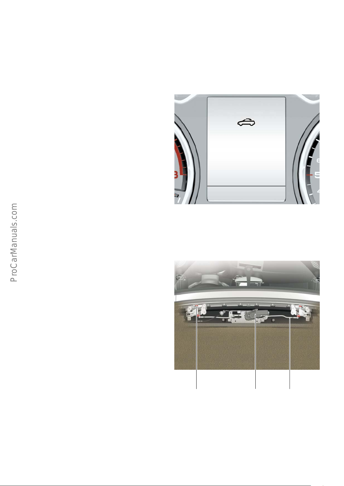
To protect the convertible top operation hydraulic pump V118
against overload, the control unit monitors the runtime of the
convertible top.
If the convertible top has been running continuously for approx. 2
minutes and is closed by this time, the control unit suppresses
operation of the convertible top for approx. 10 minutes.
The maximum continuous duty cycle of the hydraulic pump
is limited to approx. 170 seconds. This means that the hydraulic
pump shuts o after approx. 170 seconds of continuous duty,
regardless of the convertible top’s momentary position.
Operation of the convertible top is subsequently suppressed for
approx. 20 minutes due to the danger of overheating. This is
indicated by the adjacent diagram in the dash panel insert.
Convertible top:
no operation
possible
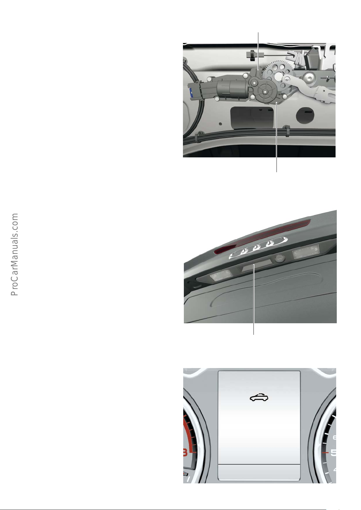
Convertible top locking motor V223
The convertible top locking motor V223 is attached to the convertible top in the middle as seen in the direction of travel.
The motor uses a linkage to actuate the two catch hooks which lock
the roof into the window frame.
623_085
623_086
40
Convertible top
locking motor V223
LinkageCatch hook
Page 41
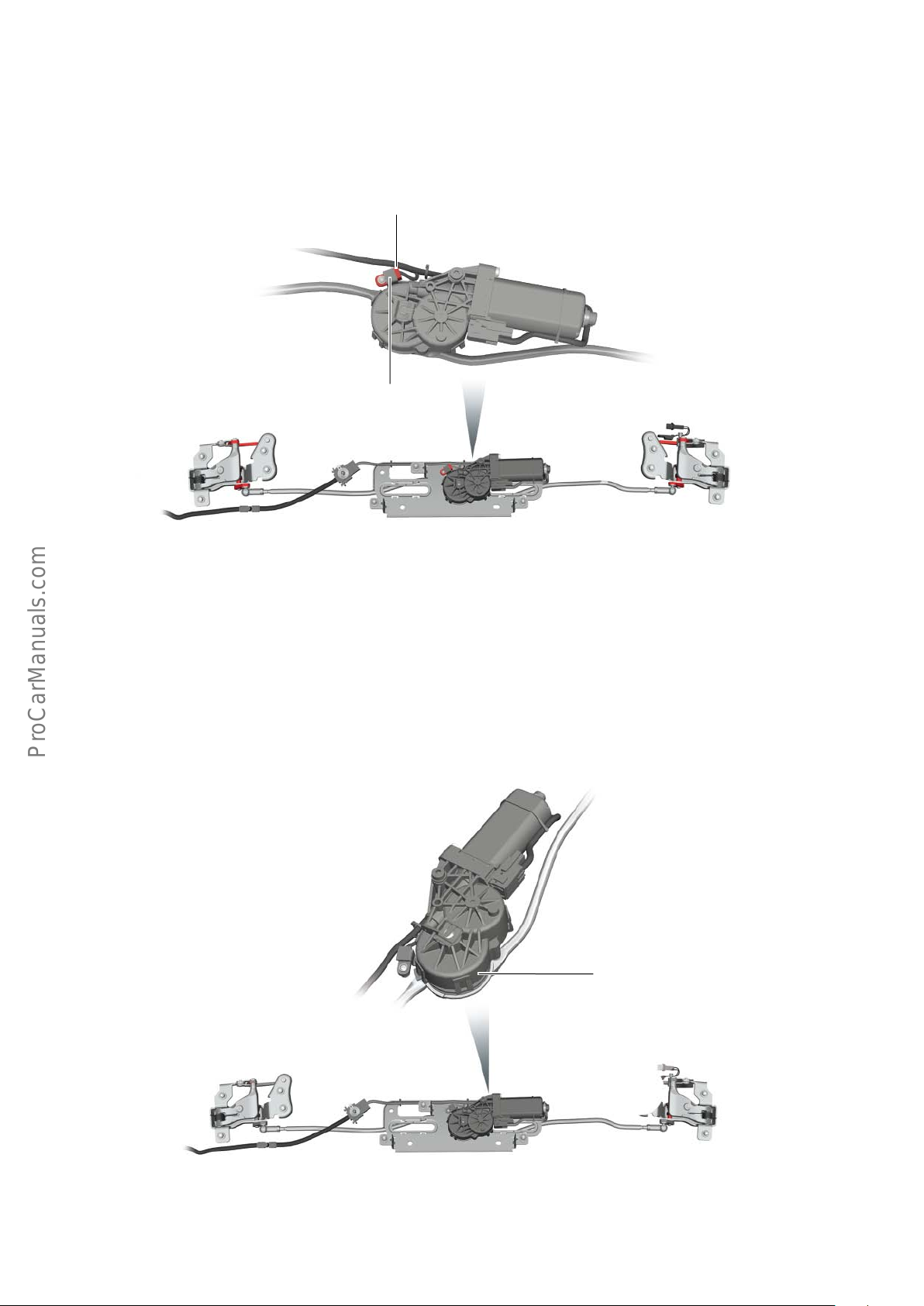
Convertible top box lid closed switch F295
The convertible top box lid closed switch F295 is built into the
convertible top locking motor V223. This switch is a Hall sensor.
Convertible top box lid
closed switch F295
Retaining plate
When the motor V223 has locked the convertible top latch, a
retaining plate is within the detection range of the Hall sensor. This
produces a signal which the convertible top operation control unit
detects as "convertible top lock closed".
623_087
Convertible top lock open switch F294
The convertible top box lid open switch F294 is built into the
convertible top locking motor V223. This switch is a Hall sensor
configured as an incremental encoder, or rotary encoder, i.e. the
Hall sensor measures the number of revolutions of motor V223.
The convertible top operation control unit evaluates the signals
generated by the Hall sensor. When the Hall sensor has measured
the corresponding number of revolutions, the convertible top
operation control unit detects "convertible top lock open".
Convertible top lock open switch F294
623_088
41
Page 42
Emergency operation
In the event of a malfunction, the convertible top can be closed
manually. If possible, the convertible top should be emergencyoperated by two persons.
The convertible top cannot be emergency-operated unless the
system is depressurised. The system depressurises automatically
approx. 5 minutes after turning the ignition o. The system can
also be depressurised manually
Closing the convertible top
Conditions:
• Parking brake closed
• All side windows lowered
• Ignition turned o
• Hydraulic system is depressurised
by turning o the ignition and pushing or pulling the convertible
top operating switch E137 for approx. 5 seconds.
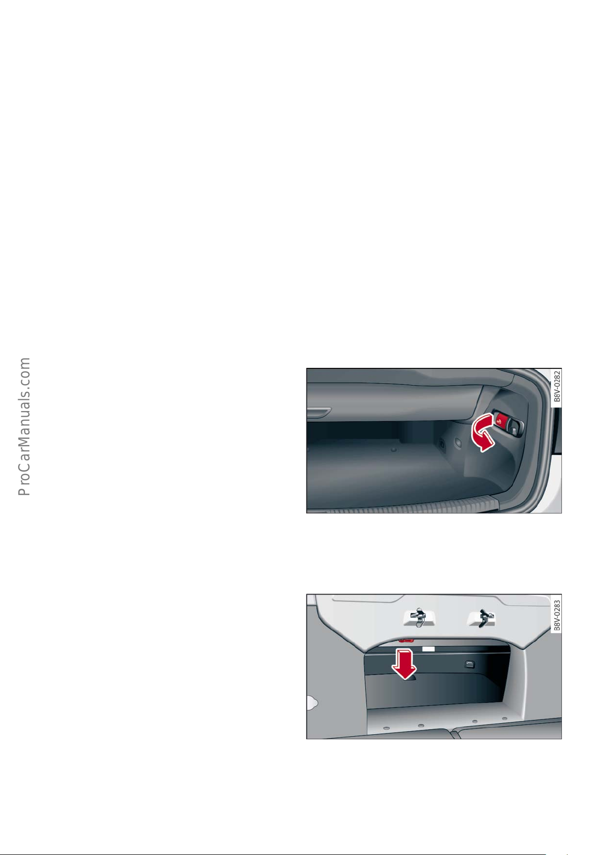
The box wrench from the vehicle's tool kit is required for manual
operation of the convertible top.
First of all, the convertible top box lid must be unlocked.
To do this, open the boot lid and fold down the backrest of the
right seat seat as seen in the direction of travel (arrow)
.
Now remove the box wrench from the vehicle tool kit and close the
boot lid. From inside the vehicle, pull down the release loop
(arrow) and unlock the convertible top box lid.
623_014
42
623_015
Page 43
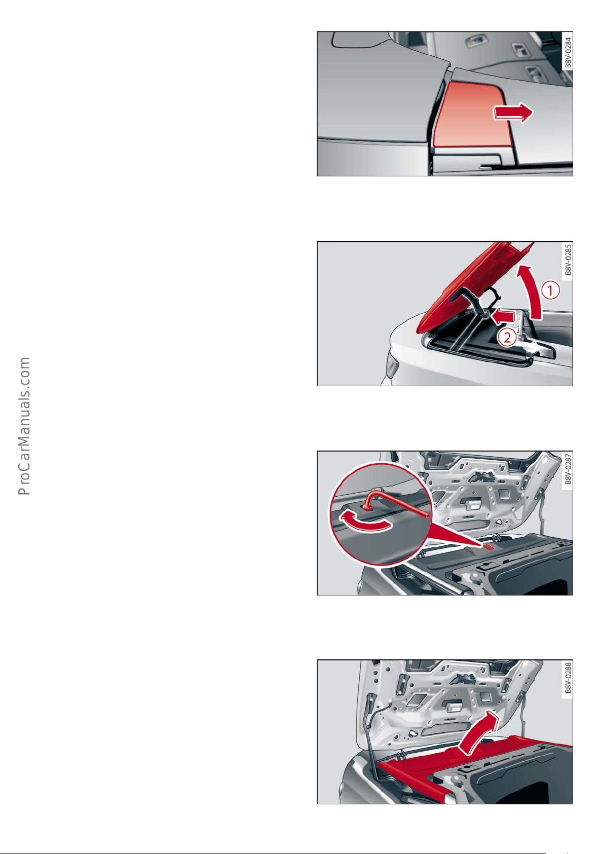
Push the covers on both sides of the vehicle in the direction of the
arrow until they engage.
As the convertible top box lid can close involuntarily and cause
injury or damage, the convertible top box lid must be held during
the entire opening cycle. Move the convertible top box lid into the
upright position (arrow 1) and hold it there with your hands. After
that, secure the convertible top box lid by pushing back the left
and right-hand hinges (arrow 2). It is no longer necessary to hold
the convertible topbox lid in this position.
623_016
Remove the cover from the trim and apply the box wrench. To open
or disengage the catch hooks, turn the box wrench clockwise as far
as it will go. Then remove the box wrench.
To lift out the convertible top, place the seat next to the vehicle,
grab the convertible top by the front edge and pull it out completely (arrow).
The convertible top tensioning strut must then be raised until the
convertible top box lid can be closed.
623_017
623_018
623_019
43
Page 44
!
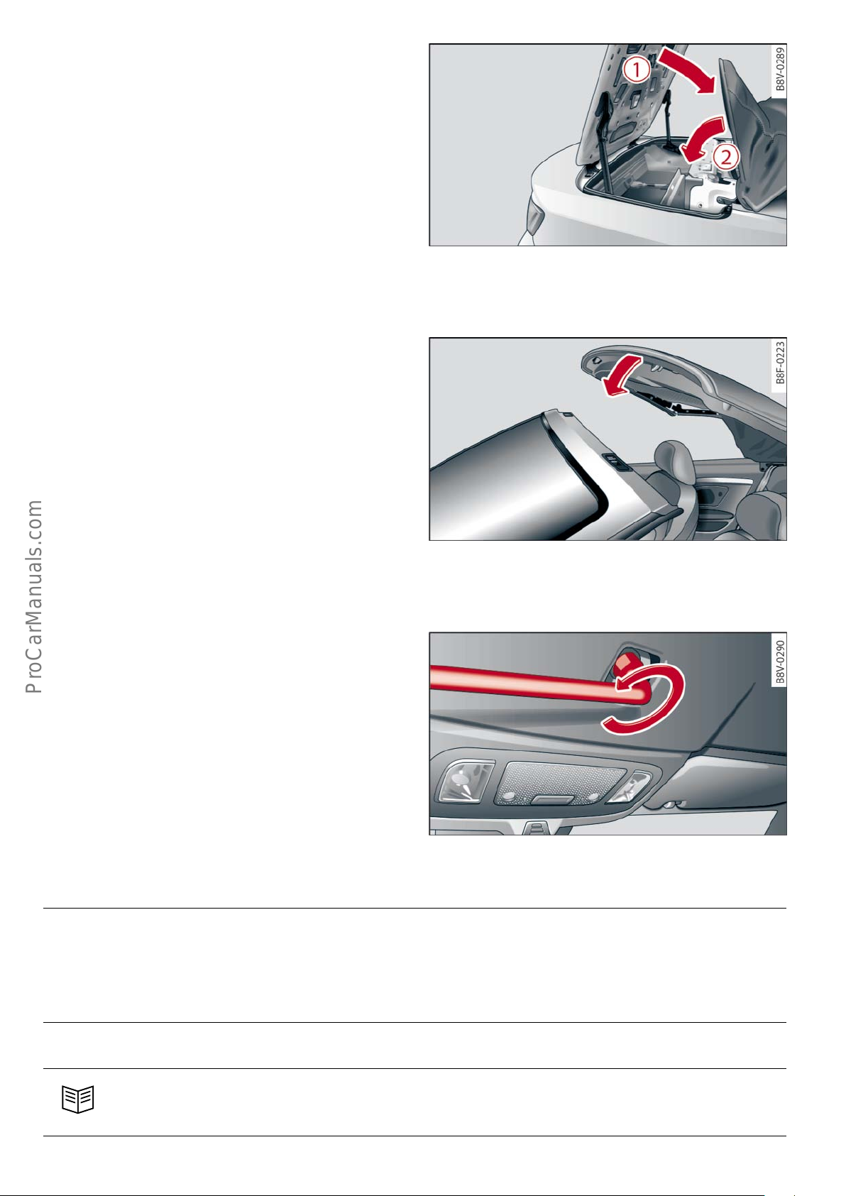
As the convertible top box lid can close involuntarily and cause
injury or damage, the convertible top box lid must be held during
the entire closing cycle. Unlock the convertible topbox lid by
pulling the left and right hinges and slowly close the lid with
manual assistance. Then lower the tensioning strut of the convertible top (arrow 2) until it rests on the convertible top box lid.
The final step is to lock the convertible top into the window frame.
For this purpose, push the convertible top onto the window frame
(arrow).
623_020
Then apply the box wrench and turn it anticlockwise as far as it will
go and remove the box wrench. Make sure that the catch hooks
engage in the top sections of the lock and that the convertible top
is correctly locked.
Note
After the convertible top has been emergency-operated, the convertible top box lid is unlocked.
623_021
623_022
Caution: do not reach into the convertible top linkage or other moving parts during emergency operation of the convertible
top. Danger of injury!
Reference
Please refer to the Owner’s Manual for further information on emergency operation.
44
Page 45
Data bus overview
The overview shows, by way of example, some of the information
exchanged via data bus.
Rear driver’s side indow regulator control unit with
motorJ1016
Rear passenger’s side indow regulator control unit with motor
J1017
Side window closing ← E
Lower side windows ← E
(LIN users of door control units J386 and J387)
Convertible top control unit J256
Locked and closed status of convertible top ← A
Unlocked status of convertible top ← A
Locked and open status of convertible top ← A
Convertible top in intermediate position ← A
Convertible top opening movement ← A
Convertible top closing movement ← A
Boot lid release enabled/disabled ← A
Side window closing → A
Lower side windows ← A
Display convertible top message in instrument cluster display → A
Comfort request via key ← A
Instrument panel control unit J285
Display convertible top message in instrument cluster display ← E
Ambient temperature → A
Door control unit, driver side J386
Front passenger door control unit J387
Locked and closed status of convertible top ← E
Side window closing ← E
Lower side windows ← E
Side window closing → A (to LIN users J1016 and J1017)
Side window opening → A (to LIN users J1016 and J1017)
Onboard power supply control unit J519 (= BCM_01)
Locked and closed status of convertible top ← E
Locked and open status of convertible top ← E
Convertible top in intermediate position ← E
Boot lid release enabled/disabled ← E
Comfort request via key ← E
Rear window heater on/o status → A
NO contact on/o status → A
Terminal 15 status → A
Convenience opening and closing request signal → A
Enable convertible top operation → A
Actual and nominal status of external vehicle locking → A
Boot lid status → A
Sleep mode readiness → A
Speed signal → E
Ambient temperature → E
Convenience opening and closing request signal → E
Sleep mode readiness → E
Rear window heater on/o status → E
NO contact on/o status → E
Terminal 15 status → E
Enable convertible top operation ← E
Boot lid status → E
Actual and nominal status of external vehicle locking → E
Key:
Climatronic control unit J255
Locked and closed status of convertible top ← E
Locked and open status of convertible top ← E
Convertible top opening movement ← E
Convertible top closing movement ← E
Data bus diagnostic interface J533 (Gateway)
Locked and closed status of convertible top ← E
Unlocked status of convertible top ← E
Locked and open status of convertible top ← E
Comfort request via key ← E
Speed signal → A
Sleep mode readiness → A
Access and start authorisation control unit J518
Locked and closed status of convertible top ← E
Convertible top opening movement ← E
Convertible top closing movement ← E
Comfort request via key ← E
Data bus in general
LIN bus
←E Receiving data (input)
→A Sending data (output)
Trailer detector control unit J345
Comfort request via key ← E
623_071
45
Page 46
Occupant safety
Components
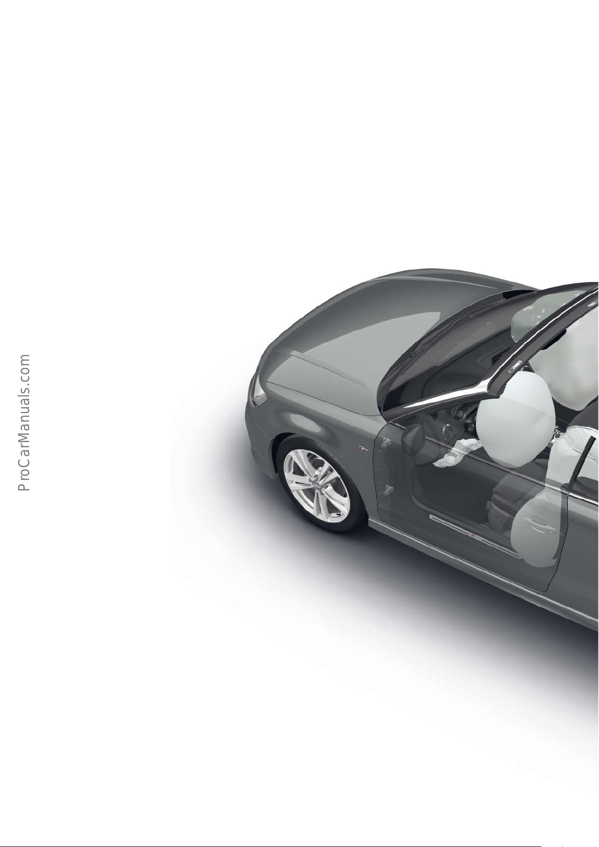
The passive occupant and pedestrian protection system
in the AudiA3’14 comprises the following components and
systems:
• Airbag control unit
• Driver and passenger airbags
• Front side airbags (head-thorax airbag)
• Driver side knee airbag
• Front airbag crash sensor
• Crash sensors for side impact detection in the doors
• Rear crash sensor for side impact detection on heel plate
• Front inertia reel seat belts with electric and pyrotechnic belt
tensioners
• Seat belt warning for all seats
• Seat belt switches on all seats in the seat belt buckles
• Seat occupancy sensor in front passenger seat
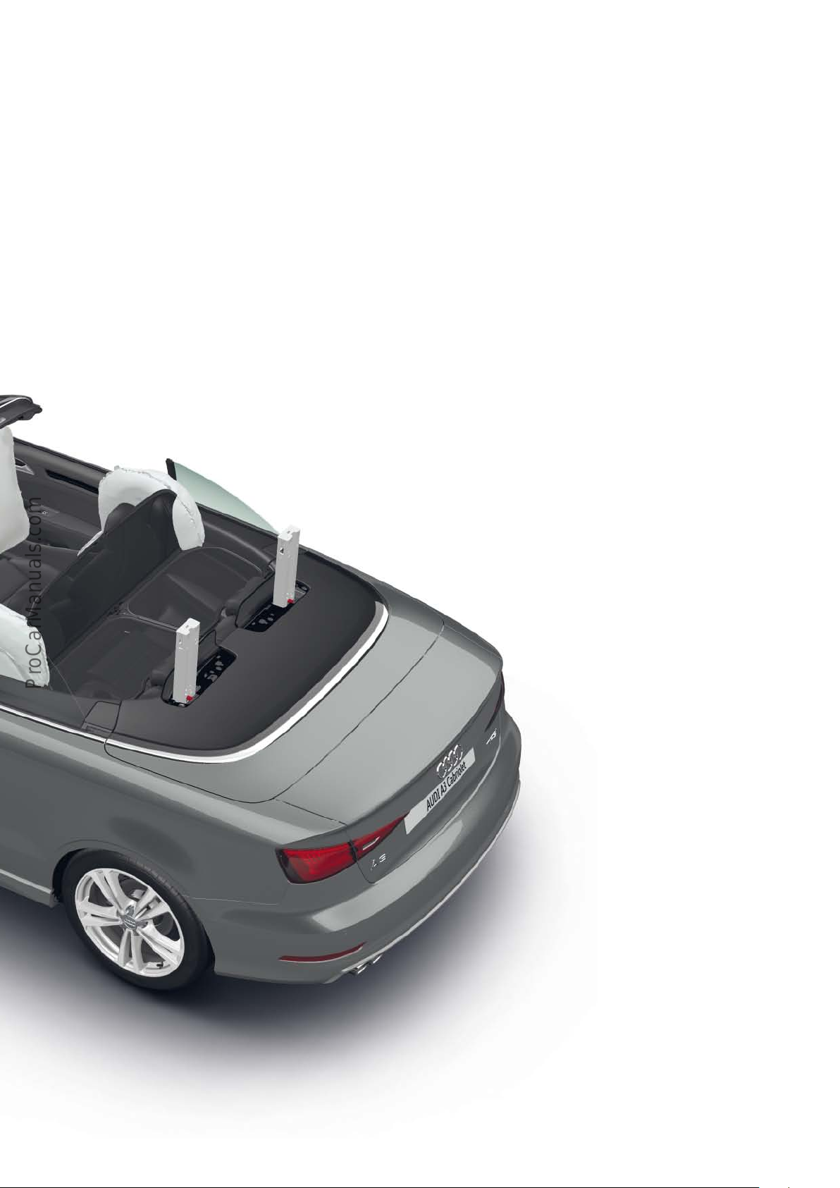
• Rollover protection
46
Page 47
Additional equipment
The vehicle is optionally available with a key-operated disabling
switch for the front passenger front airbags with accompanying
warning lamp.
Due to the dierent statutory provisions and requirements for car
makers in the various markets, equipment specifications may vary.
623_005
47
Page 48
System overview
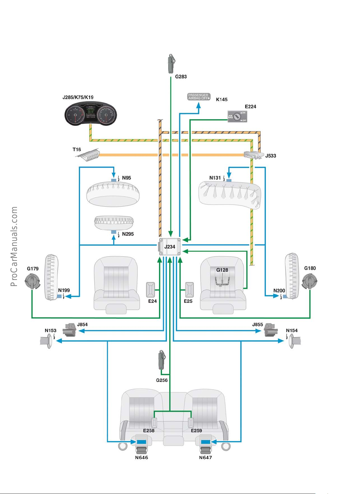
The system overview shows, by way of example, the equipment options available for a German-specification vehicle.
48
623_006
Page 49

Key to illustration
E24 Driver side seat belt switch
E25 Passenger side seat belt switch
E224 Airbag disabling switch,
passenger side (optional)
E258 Rear seat belt switch, driver side
E259 Rear seat belt switch, passenger side
G128 Passenger side seat occupancy sensor
G179 Side airbag crash sensor, driver side
G180 Side airbag crash sensor, passenger side
G256 Rear side airbag crash sensor, driver side
(centre of heel plate)
G283 Front airbag crash sensor, driver side (front end)
J234 Airbag control unit
J285 Control unit in dash panel insert
J533 Data bus diagnostic interface (gateway)
J854 Front left seat belt tensioner control unit (optional)
J855 Front right seat belt tensioner control unit (optional)
K19 Seat belt reminder warning lamp
K75 Airbag warning lamp
K145 Passenger airbag o warning lamp (optional)
N95 Driver side airbag igniter
N131 Passenger side airbag igniter 1
N153 Seat belt tensioner igniter 1, driver side
N154 Seat belt tensioner igniter 1, passenger side
N199 Side airbag igniter, driver side
N200 Side airbag igniter, passenger side
N646 Rollover protection trigger, driver side
N647 Rollover protection trigger, passenger side
T16 16-pin connector, diagnostic port
Powertrain CAN bus
Convenience CAN bus
Diagnostics CAN bus
Input signal
Output signal
49
Page 50
Side airbag
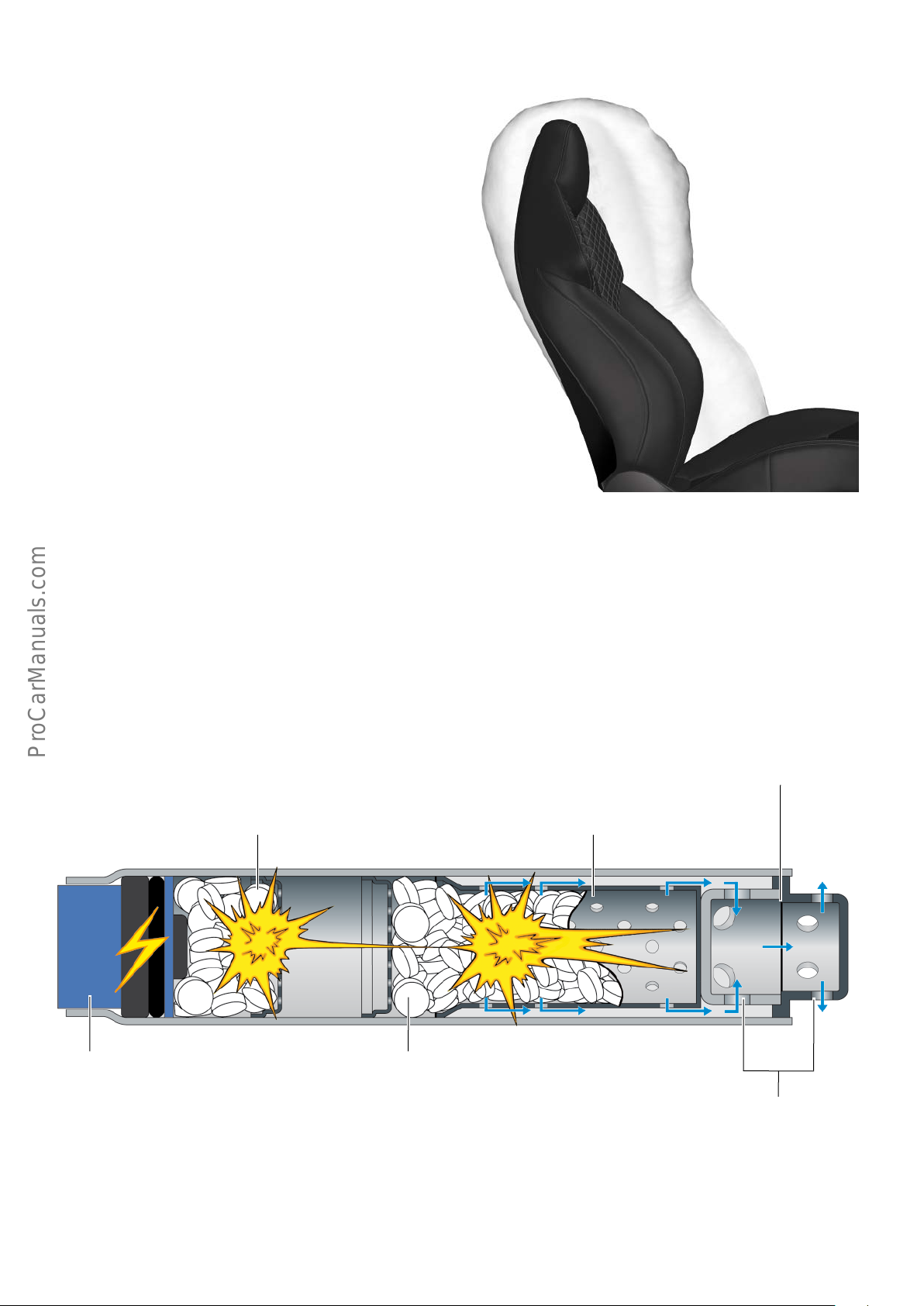
The side airbags, side airbag igniter, driver side N199, and side
airbag igniter, passenger side N200 are configured as head-thorax
airbags.
The head-thorax airbags are designed to protect not only the body,
but also the head of the front
occupants.
The side airbags on the Audi A3 Cabriolet ’14 have approx. 8.5
litres more capacity than the side airbags on the A3 and the A3
Sportback.
By integrating the side airbags in the front seat backrests, the
airbags are optimally positioned relative to the front occupants
irrespective of the seat setting.
The side airbag igniter activated by the airbag control unit (fusible
resistance wire including a small quantity of pyrotechnics) ignites
the priming charge. This in turn ignites the actual propellant
charge, which in this case is a pyrotechnic solid propellant.
The gases liberated during combustion of the propellant charge
flow through outlet orifices via the filter into the airbag, which
Priming charge
623_011
then unfolds and fully inflates. The seal between the outlet orifices
protects the pyrotechnics against moisture and is destroyed by the
heat generated.
Seal
Filter
(contains the propellant charge)
50
Igniter
623_012
Propellant charge
Outlet orifices
Page 51
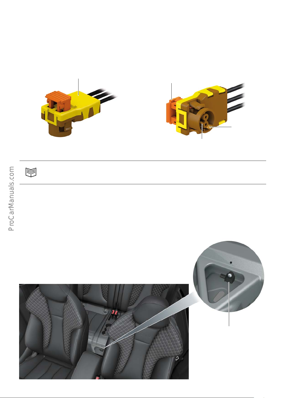
Electrical wiring loom for side airbag
The electrical wiring loom of the front side airbag can be completely replaced on the Audi A3 Cabriolet ’14. Therefore, it is no
longer necessary to replace the complete airbag module if the
wiring loom is damaged.
Cover
609_014a
This is possible because the ground cable used to protect the
pyrotechnics against static connects directly to the airbag module
connector. After contacting the connector, the ground cable
connects the gas generator housing to the body in an electrically
conductive manner.
Locking device
Contact
Mechanically encoded housing
609_014
Reference
Please refer to the information given in ETKA.
Rear side airbag crash sensor, driver side G256
The side airbag crash sensor, rear driver side G256 is a capacitive
acceleration sensor. Although crash sensor G256 is designated
"rear driver side", it is fitted in the rear of the vehicle at the centre
of the heel plate. If G256 senses a side impact, it informs the
airbag control unit. The Y sensor integrated in the control unit
checks the crash signal from G256 for plausibility.
As soon as a deployable impact is detected, the airbag control unit
deploys the belt tensioners and the head-thorax airbag on the
impact-facing side of the vehicle.
623_013
Rear side airbag crash sensor,
driver side G256
51
Page 52
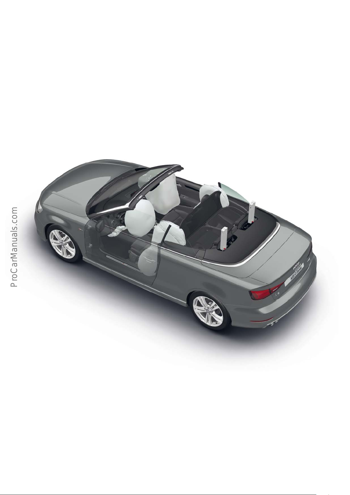
Rollover protection
Without special modifications, cabriolets would not adequately
protect their occupants during a rollover accident as they do not
have a rigid roof. To counteract this, the Audi A3 Cabriolet ’14 is
equipped with a rollover protection system.
In contrast to the outgoing model, which has a rigid rollover
protection system, the Audi A3 Cabriolet ’14 is equipped with a
retractable rollover protection system.
When deployed, the rollover protection system, together with the
body strengthening measures and the rigid A posts, provides a
survival space for the occupants.
An additional sensor detects an imminent rollover and deploys the
rollover protection system. This sensor is known as a "roll over
sensor" and is integrated in airbag control unit J234. The roll over
sensor cannot be replaced separately.
If an imminent rollover is detected, the rollover protection system
deploys and the belt tensioners are ignited.
In all crash events in which airbags and/or belt tensioners are
ignited, the rollover protection system deploys as a precautionary
measure. If no rollover occurs in the course of the crash, the
rollover protection system can easily be reset due to its reversability.
623_005a
52
Page 53
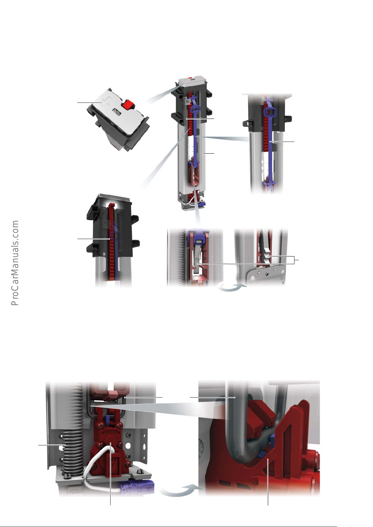
Cassettes with anti-roll bars
The rollover protection system on the Audi A3 Cabriolet ’14 consists of two cassettes which accommodate the anti-roll bars and
other components.
Dierent cassettes are used on the driver and passenger sides.
Therefore, care must be taken to ensure that the cassettes are
fitted on the correct side of the vehicle.
Arrow indicating
installation direction
The correct installation direction of the cassettes is indicated by an
arrow on the cassettes. The specified tightening sequence must be
adhered to.
Spring
Release lever
Cassette
Ratchet rail
Rollover protection trigger, driver side N646 and rollover
protection trigger, passenger side N647
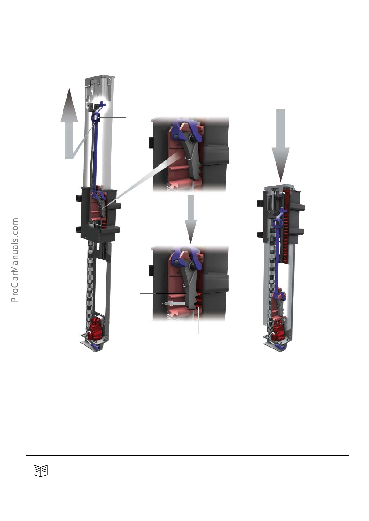
The retractable anti-roll bars are preloaded by a spring. The antiroll bar is held in its lower position by the U bar of the rollover
protection trigger. When the rollover protection trigger is energised by the airbag control unit J234 due to an imminent rollover
or crash, the trigger releases the U bar and the anti-roll bar
U bar
deploys upwards within approx. 130 milliseconds. In the fully
extended position, the pawl engages the ratchet rail and thus
prevents the anti-roll bar from being pushed back.
Pawl
623_007
Spring
623_008
Rollover protection trigger Rollover protection trigger
53
Page 54
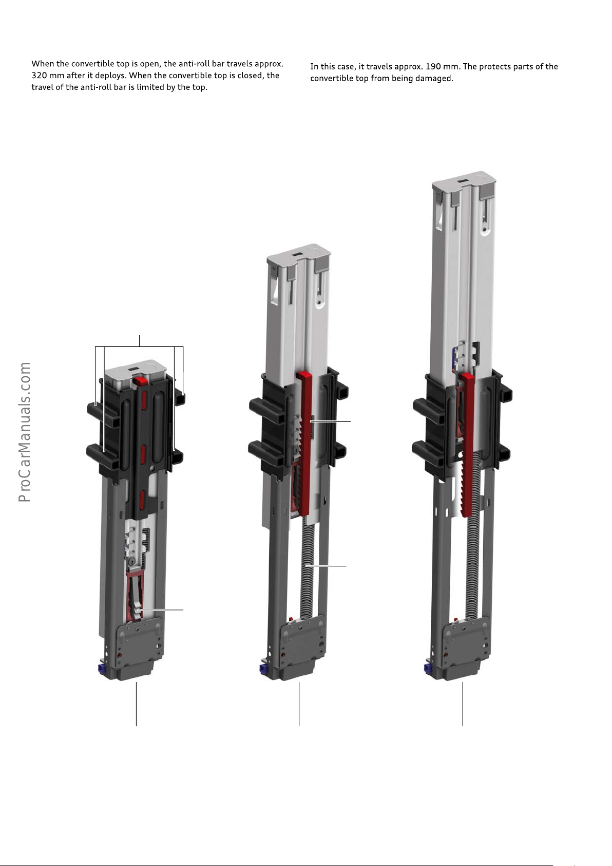
When the convertible top is open, the anti-roll bar travels approx.
320 mm after it deploys. When the convertible top is closed, the
travel of the anti-roll bar is limited by the top.
In this case, it travels approx. 190 mm. The protects parts of the
convertible top from being damaged.
Deployed rollover protection system N647
Bolting points
Ratchet rail
Spring
Pawl
623_009
Preloaded position Fully extended position when
54
convertible top is closed
Fully extended position when
convertible top is open
Page 55
Resetting a deployed anti-roll bar
Pulling the release lever 1 pulls the pawl 2 out of the ratchet rail 3
and releases the anti-roll bar.
1
The rollover protection system can be reset by pushing back the
anti-roll bar 4 at the same time (the U bar must lock into place).
4
2
Diagnostics
The rollover protection trigger, driver side N646 and rollover
protection trigger, passenger side N647 are monitored by the
airbag control unit J234 and are diagnosable. As soon as the airbag
control unit J234 detects an event, the event is stored. The event
can be diagnosed using the Guided Fault Finding.
The rollover protection system of the Audi A3 Cabriolet ’14 can be
deployed by an actuator diagnostic system. The airbag control unit
J234 counts the number of deployments of the rollover protection
system.
Reference
For further information about the rollover protection system, refer to the Workshop Manual, the Guided Fault Finding and
the maintenance schedule.
3
623_010
The number of deployments is limited and can be determined from
the measurement data. If the number of deployments reaches
127, the event "rollover protection system faulty" is registered by
airbag control unit J234, and the cassettes have to be replaced.
Therefore, unnecessary deployments should be avoided. The
rollover protection system must be inspected by service personnel
according to the maintenance schedule.
55
Page 56
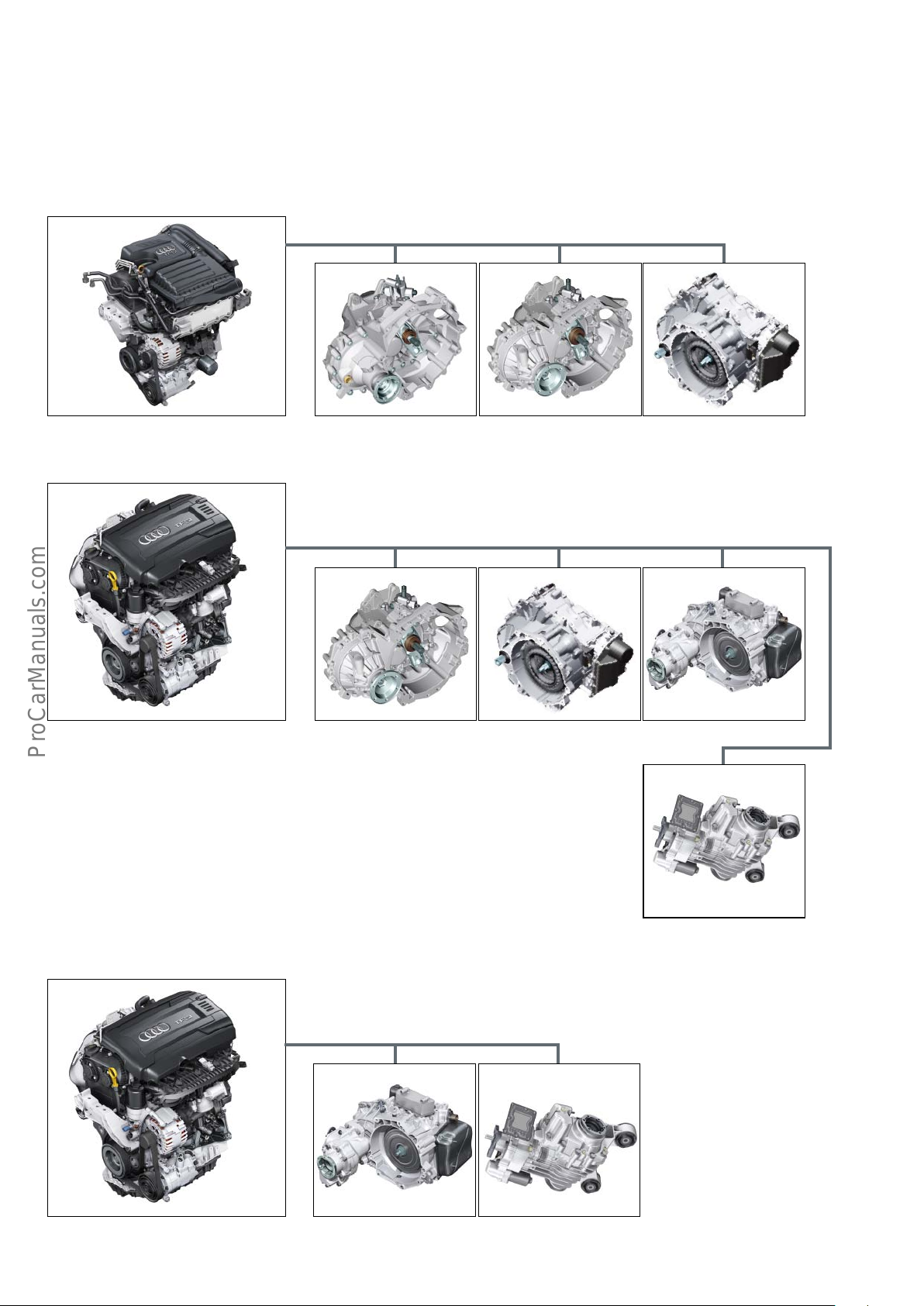
Engine/gearbox combinations
The engine-gearbox combinations shown below are those available at market launch.
Petrol engines
1.4l TFSI engine
0AJ 02S 0CW
1.8l TFSI engine
2.0l TFSI engine
0CW02S 0D9 quattro
0CQ
56
0D9 quattro 0CQ
Page 57
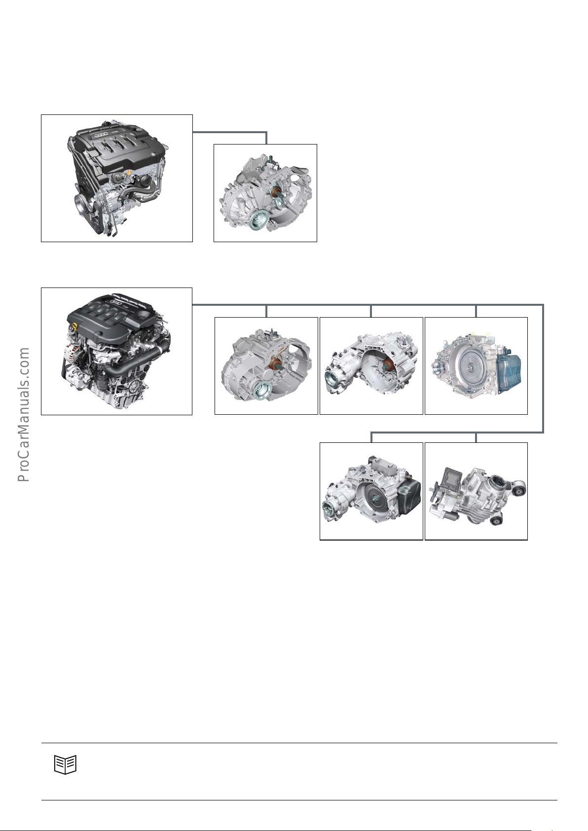
Diesel engines
1.6l TDI engine
2.0l TDI engine
02S
Gearbox codes:
0AJ (MQ200_6F)
02S (MQ250_6F)
02Q (MQ350_6F/_6A)
0FB (MQ350_6F)
0CW (DQ200_7F)
0D9 (DQ250_6F/_6A)
0CQ Rear axle final drive unit (Haldex) V
(5th generation Haldex coupling)
02Q/0FB 02Q 0D9 front
0D9 quattro
Breakdown of manufacturer codes:
e.g. MQ350-6F
M Manual gearbox
D Double-clutch gearbox
Q Transverse installation
350 Nominal torque capacity
6 Number of gears
F Front wheel drive
A All-wheel drive (quattro)
0CQ
Reference
For further information about engines and gearboxes as well as the rear axle final drive unit of the Audi A3’13, refer to Self
Study Programme 609 "AudiA3’13".
57
Page 58
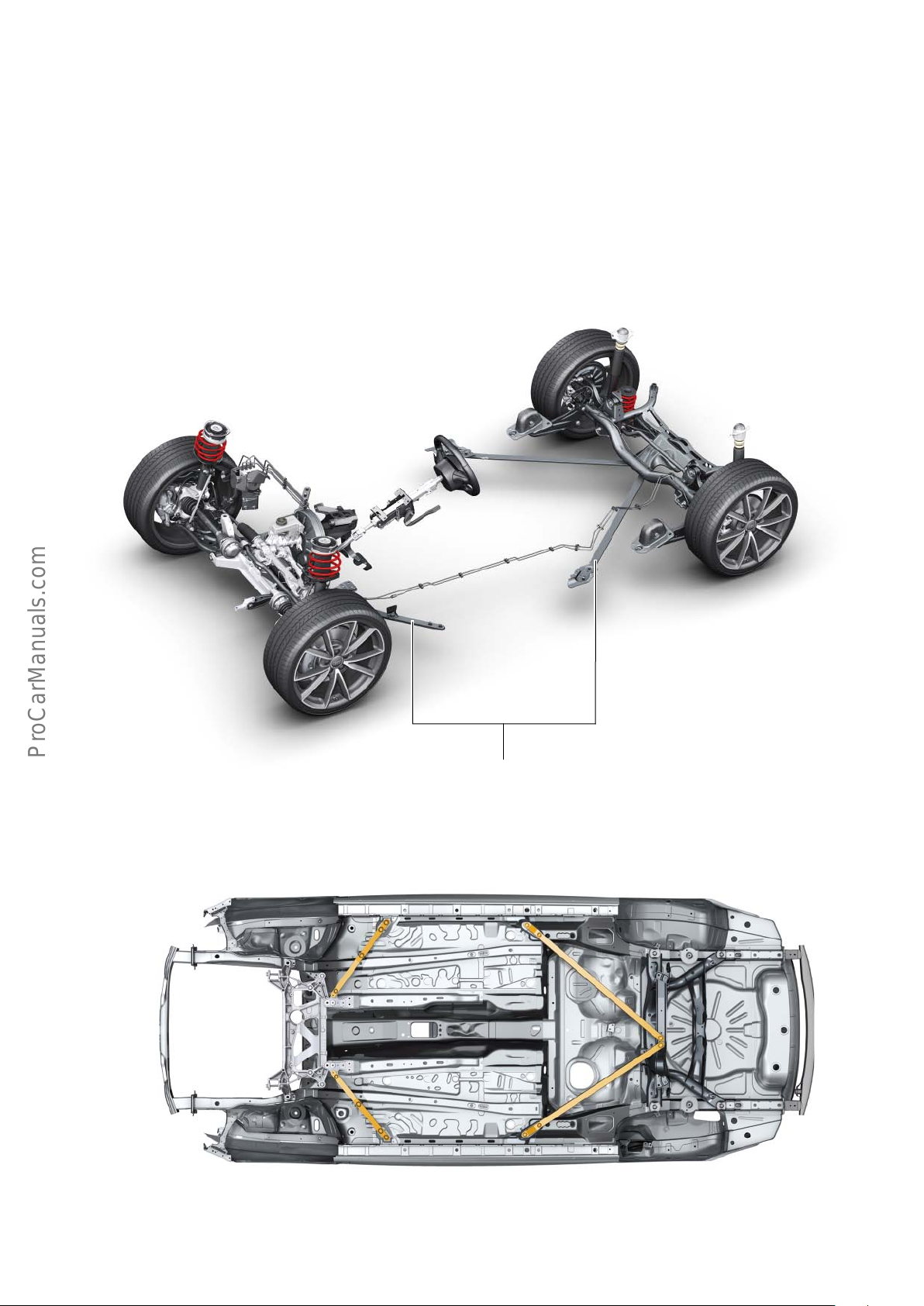
Suspension
Overall concept
The suspension of the Audi A3 Cabriolet ’14 impresses with sporty
handling, superior driving safety and a high level of comfort.
By using key suspension components from the Audi A3 ’13, special
emphasis was placed on lightweight design as part of the Audi
Ultra Strategy. The axle components are part aluminium.
Dynamic suspension is standard, while sports suspension and S
line sports suspension are optional. As compared to the dynamic
suspension system, ride height is 15 mm lower with sports suspension and 25 mm lower with S line sports suspension. An
optional suspension with Audi magnetic ride adaptive damper
control and the same ride height as the S line sports suspension
rounds o the product range. The wheels options are adopted from
the Audi A3 saloon*.
623_103
The front and rear axle carriers are connected to the car body by
additional cross pieces. This provides a high level of vehicle rigidity
and vibration comfort.
* See overview of wheel and tyres in SSP 625.
58
623_104
Page 59
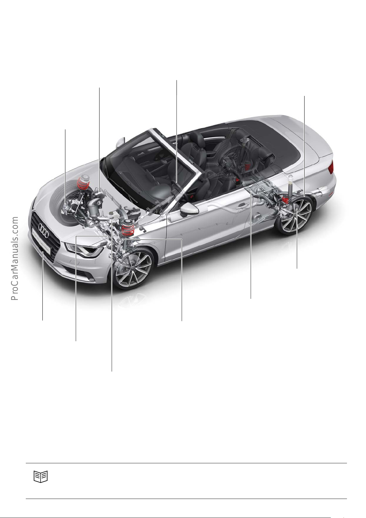
Overview
Continental ESC MK100*
second generation tyre
pressure monitoring
system* as option
15 or 17 inch front wheel
brakes* depending on
engine version
Four-spoke steering wheel* as standard;
four-spoke steering wheels and three-spoke
sports wheel in various versions as options
16“-19“ wheels with "Tire Mobility System" as
standard; a space saver spare wheel is optional
for front wheel drive vehicles
ACC* is optional
Electro-mechanical steering*
with Servotronic function as
standard
Tandem master brake cylinder* with
single 10“ or 11“ brake servo for lefthand drive models
Tandem master brake cylinder* with
single 7“/8“ or 8“/8“ brake servo for
right-hand drive models
623_105
15" rear wheel brakes with electro-mechanical parking brake
(EPB)
Four-link rear axle* for front
wheel drive and quattro drive
McPherson front axle*, subframe
and swivel bearing in combination
with 16“ aluminium brake system
* Identical in terms of design and functional principle to the systems/components on the current Audi A3 ’13.
Reference
For detailed information about the design and function of the electro-mechanical steering system, refer to Self Study Programme 612 "AudiA3’04 Suspension".
59
Page 60
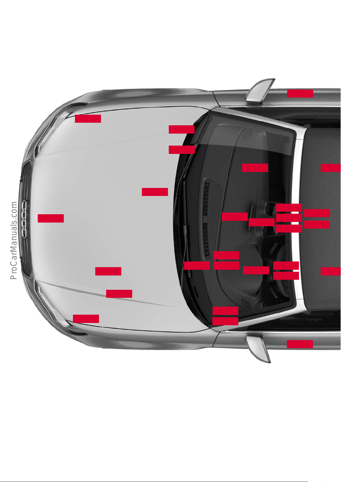
Electrical system
Installation locations of control units
Some of the control units shown in the overview are optional and/
or country-specific equipment.
J668
J500
J428
Refer to the current service literature for details of control unit
positions, as well as instructions for installation and removal.
J387
J104
J869
J794
R242
J685
J234
J844
J255
J250
E380
J587
J743
J623
J667
Key:
E380 Multimedia system operating unit
J104 ABS control unit
J234 Airbag control unit
J250 ECD control unit (electronically controlled damping)
J255 Climatronic control unit
J256 Convertible top operation control unit
J285 Control unit in dash panel insert
J345 Trailer detector control unit
J386 Driver side door control unit
J387 Passenger side door control unit
J518
J745
J533
J791
J519
J285
J428 ACC control unit
J492 All-wheel drive control unit
J500 Power steering control unit
J518 Entry and start authorisation control unit
J519 Onboard power supply control unit
J525 Digital sound package control unit
J527 Steering column electronics control unit
J533 Data bus diagnostic interface
J527 Selector lever sensors control unit
J608 Special vehicle control unit
J527
J764
J525
J386
60
Page 61
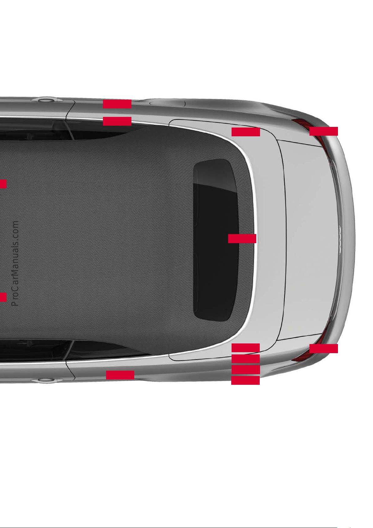
J1017
R78
J772
J492
J769
J1016
J623 Engine control unit
J667 Headlight power module, left
J668 Headlight power module, right
J685 MMI display
J743 Twin clutch gearbox mechatronics
J745 Cornering light and headlight range control unit
J764 Electrical steering column lock control unit
J769 Audi lane assist control unit
J770 Audi lane assist control unit 2
J772 Reversing camera system control unit
J345
J843
J608
J256
J770
623_097
J791 Audi parking system control unit
J794 Information electronics control unit 1
J843 Vehicle tracking system interface control unit
J844 Headlight assist control unit
J869 Structure-borne sound control unit
J1016 Rear driver's side window regulator control unit with motor
J1017 Rear passenger's side window regulator control unit with
motor
R78 TV tuner
R242 Front camera for driver assistance systems
61
Page 62
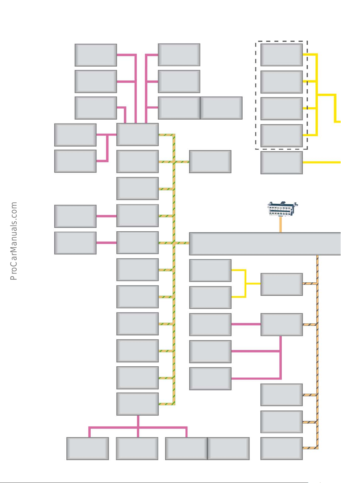
Topology
Sliding sunroof
adjustment control
unit
J245
Anti-theft alarm
sensor
G578
Alarm horn
H12
L/H head space
heating control
unit
J846
R/H head space
heating control
unit
J847
Rear driver’s side
indow regulator control unit with motor
J1016
Onboard power
supply
control unit
J519
Control unit in dash
panel insert
J285
Steering column
electronics
control unit
J527
Driver side
door control unit
J386
Light switch E1
Control unit for
wiper motor
J400
Rain and light detector sensor
G397
Convertible top
operation control
unit
J256
Humidity sensor
G355
Power module for
left headlight
J667
Headlight power
module, right
J668
or
Power output module for left LED
headlight
Power output module for right LED
headlight
Audi side assist
control unit 2
J770
Diagnostic port
Rear passenger’s side
indow regulator control unit with motor
J1017
Passenger side
door control unit
J387
Trailer detector
control unit
J345
Entry and start
authorisation control unit
J518
Electronic steering
column lock control
unit
J764
Vehicle tracking
system interface
control unit
J843
Special vehicle control unit
J608
Climatronic
control unit
J255
1)
Data bus diagnostic interface
J533
NOx sender control
unit
J583
NOx sender control
unit 2
J881
Seat occupancy recognition control
unit
J706
Front left seat belt
tensioner control
unit
J854
Front right seat
belt tensioner control unit
J855
Engine control unit
J623
Airbag
control unit
J234
Twin clutch gearbox mechatronics
J743
62
Refrigerant circuit
pressure sender
G805
Headlight range
Fresh air blower
J126
Humidity sender in
fresh air intake
duct
G657
Air quality sensor
G238
Selector lever sensors control unit
J587
Structure-borne
sound control unit
J869
Page 63
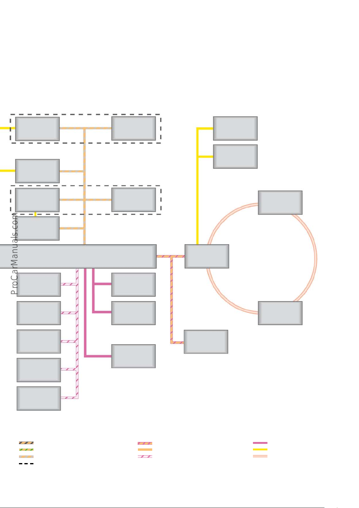
The topology shows all control units with connectivity to the data
bus system. Some of the control units shown here are optional or
country-specific equipment, or due to be introduced at a later
date.
This diagram showing all possible control units is entirely theoretical. For example, the adaptive light and headlight range control
unit J745 is never fitted in combination with the headlight range
control unit J431; only one or the other is available.
Cornering light and
headlight range
adjustment control
unit
J745
Audi side assist
control unit
J769
Front camera for
driver assistance
systems
R242
Adaptive cruise
control unit
J428
ABS control unit
J104
or
or
Headlight range
control unit
J431
Headlight assist
control unit
J844
Battery monitor
control unit
J367
Multimedia system
control panel
E380
MMI display
J685
Information electronics control unit
1
J794
Digital sound package
control unit
J525
Power steering control unit
J500
Four-wheel drive
control unit
J492
Park assist steering
control unit
J791
ECD control unit
(electronically controlled damping)
J250
Generator
C
Multifunction
steering wheel control unit
J453
Reversing camera
system control unit
J772
Key:
Powertrain CAN bus Infotainment CAN bus
Convenience CAN bus
Diagnostics CAN bus
Extended CAN bus Suspension CAN bus
"OR" configuration
1)
For more details of heater / air conditioning configurations, refer to SSP 609 "AudiA3’13".
TV tuner
R78
LIN bus
Sub-bus systems
MOST bus
623_098
63
Page 64
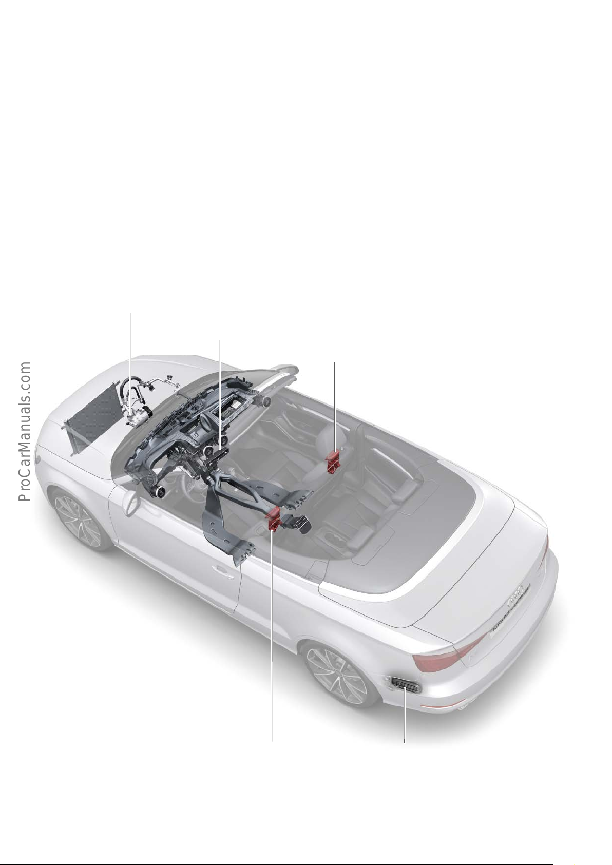
!
Air conditioning
Introduction
Air conditioning system versions
The Audi A3Cabriolet ’14 is available with dierent heating and air
conditioning equipment:
• with a manually controlled air conditioning system
• with an automatically controlled air conditioning system
Depending on country specification, both versions may not always
be available in certain markets.
The automatic air conditioning system has a moisture and enthalpy
control system. The moisture control system is used to detect
windscreen fogging, and the data it provides is factored into
calculating the stop phases in start-stop mode.
Air conditioning compressor regulating valve N 280
Climatronic control unit J255
Enthalpy is a measure of the energy content in the air conditioning
system. In the Audi A3Cabriolet ’14, ecient air conditioning is
ensured by precision control of the fresh-air-to-recirculated-air
ratio inside the vehicle.
In eciency mode (Audi drive select), the air conditioning system
is configured to operate at maximum energy eciency within
temperature thresholds compatible with climate comfort. The
automatic air conditioning system switches to the eco mode
indicated in the Climatronic control unit J255.
R/H head space heating
control unit J847
L/H head space heating
control unit J846
623_096
Left vent frame
Note
No factory-fitted auxiliary heater is available for the Audi A3 Cabriolet ’14.
64
Page 65
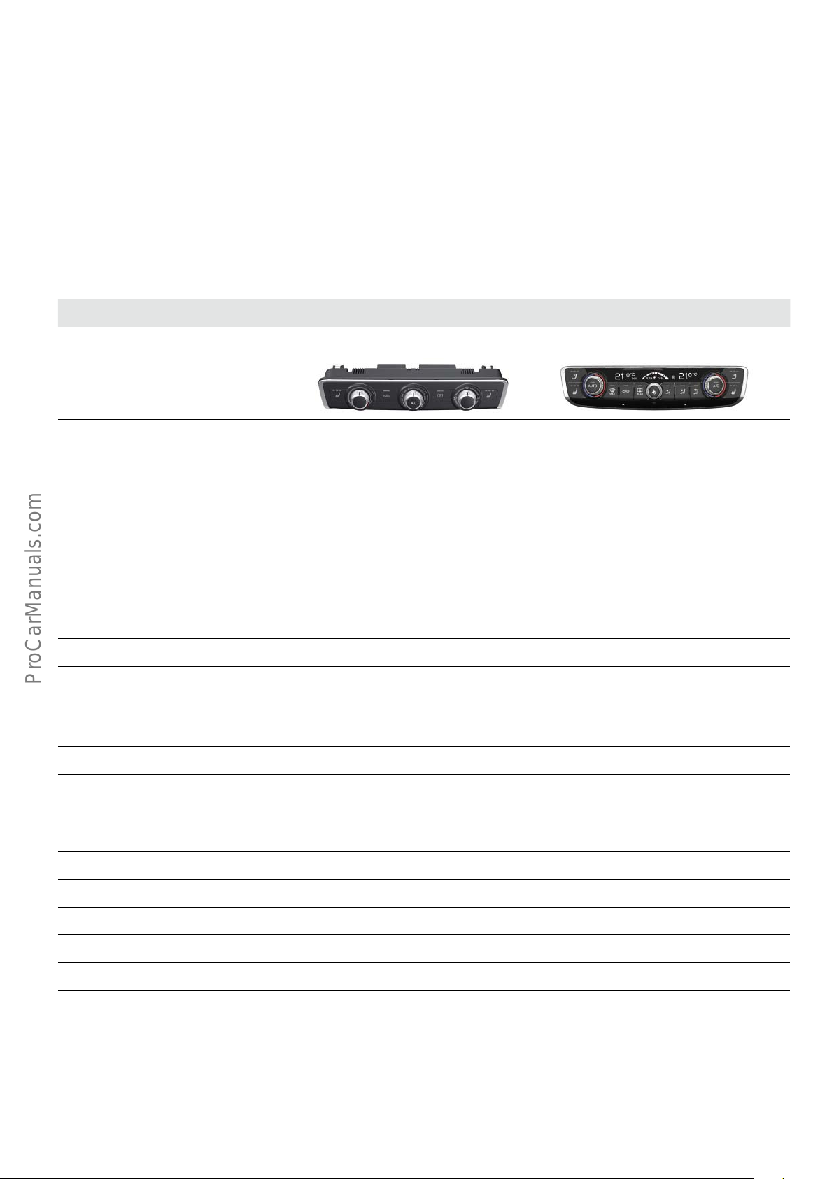
Operation
The various versions dier from one another with respect to their
equipment specification. All versions are optionally available with
a seat heater control button. The seat heater is a three-stage
Some of the rotary controls in the two versions with A/C have
multiple functions, such as turning the cooling or automatic air
conditioning ON/OFF.
system, and the selected heating level is indicated by an LED in the
respective button.
The table summarises the main functions of each version:
Manual air conditioning system Automatic air conditioning system
Control panel and control unit Air conditioning control unit J301 without display Climatronic control unit J255 with display
Functions on the control panel Three rotary controls for:
• Temperature
• Blower
• Air flow distribution
Manual air recirculation button
Heated rear window button
Optional seat heater button, three-stage
AC button
Number of temperature zones 1 2
Two rotary controls for drive and passenger side
vent temperature
AC button
AUTO button
Rotary blower control
Defroster button
Manual air recirculation button
Heated rear window button
Three buttons for setting the air distribution
Optional seat heater button, three-stage
Head space heating option:
the buttons for the two head space heaters in the
front seats are located above the seat heter
button in the Climatronic control unit J255
Air flow and air flow distribution in the occupant
cell
Moisture and enthalpy control system no
AC modes no Two AC modes
Automatic aire recycle control no
Air quality sensor no
Sun sensor no
Interior moisture sensor no
Exterior moisture sensor no
Glove compartment cooling no no
Defroster nozzles
Dash panel vents, left-centre-right
Footwell vents, right/left
Rear footwell vents, right/left
Defroster nozzles
Dash panel vents, left-centre-right
Footwell vents, right/left
Rear footwell vents, right/left
Rear vents
l
• normal
• eco
l
l
l
l
l
65
Page 66
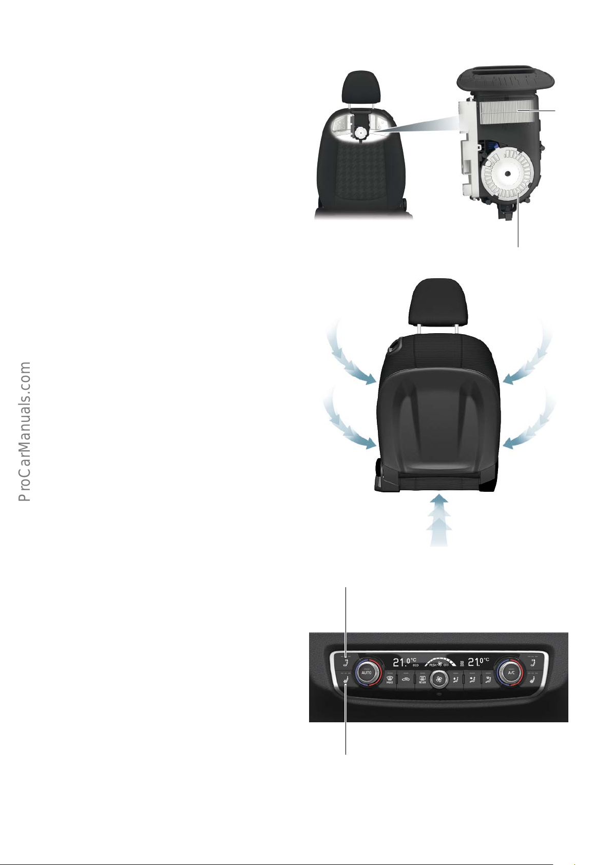
Head space heating in the Audi A3 Cabriolet ’14
Head space heating is optional for the front seats in the Audi A3
Cabriolet ’14. Sports seats can also be ordered with head space
heading as an option.
Head space heating control unit J846/J847
Head space heating via the air vents on the upper edge of the
backrest provides cozy warmth in the head, neck and shoulder
areas of the driver and front passenger.
Head space heating can be switched on when the engine is
running, even if the convertible top is open.
The front seats with head space heating have no air intakes in the
Audi A3 Cabriolet ’14. The air required for head space heating is
aspirated from the entire seat.
To ensure that enough air flows to head space heating control units
J846 and J847, neither the seat fabric nor the rear seat cover are
hermetically sealed.
PTC heating
element
623_091
Fan
The head space heating system is operated via the head space
heating buttons, which are integrated in the Climatronic control
unit J255 and arranged above the seat heater buttons.
Three settings can be selected.
When the head space heating is "on", this is indicated by LEDs in
the buttons according to setting.
The head space heating intensity level depends on the setting
selected and on the position of the convertible top. If the convertible top is open, the heating output of the PTC element and the air
flow rate are increased in each setting.
623_092
Head space heating
button, driver's seat
Climatronic control unit J255
623_093
Seat heater button,
driver's seat
66
Page 67
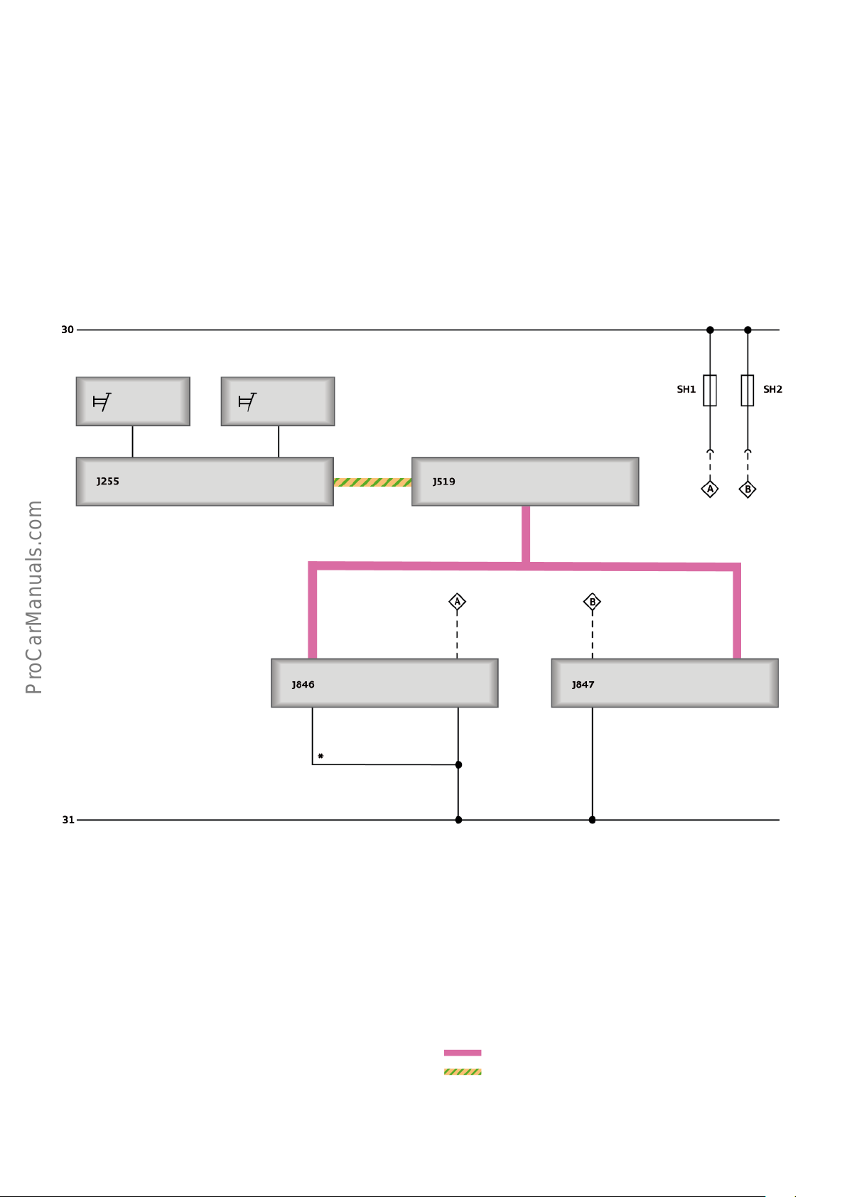
Integration of the head space heating into the vehicle's electrical system
The head space heating system has a high power consumption of
approx. 20A per front seat module.
The information provided by the head space heating buttons is
imported by the Climatronic control unit J255 and made available
to the onboard power supply control unit J519 via convenience CAN
data bus. The onboard power supply control unit transmits the
activated head space heating setting and the convertible top open
or closed position by LIN signal.
HSH button,
left
HSH button,
right
Convenience
CAN bus
The left/right head space heating control units then actuate the
corresponding blower setting and the heating output of the PTC
element.
The identical heating space heating modules are then assigned to
the driver's or passenger's seat on the basis of a ground coding.
LIN
623_094
Head space heating (HSH) button, left
Head space heating (HSH) button, right
J255 Climatronic control unit
J519 Onboard power supply control unit
J846 L/H head space heating control unit
J847 R/H head space heating control unit
SH1 Fuse 1 on fuse holder H
SH2 Fuse 2 on fuse holder H
* PIN coding wire
LIN
Convenience CAN bus
67
Page 68

Infotainment
The same infotainment equipment is available for the Audi A3
Cabriolet ’14 as for the Audi A3 ’13. Therefore, the Modular Infotainment System is also installed on the Audi A3 Cabriolet ’14.
Reference
For further information on the trim versions and the Modular Infotainment System, refer to SSP 609 – Audi A3 ’13 as well as
SSP 618 – Audi - Modular Infotainment System and the SSP 625 A3 saloon.
Sound system
In terms of design and performance, the sound systems for the
Audi A3 Cabriolet ’14 are basically identical to those for the
Audi A3 ’13.
A special feature of the Audi A3 Cabriolet ’14 is the loudspeaker
control system:
• In the Basic Sound System (8RE), Basic Plus Sound System
(8RM) and Audi Sound System (9VD), the output level is
increased by approx. 2 dB when the convertible top is open.
• In the Bang and Olufsen Sound System (9VS), a special sound
tuning feature is activated depending on the convertible top's
position. In addition, the sound tuning is adapted dynamically
to the ambient noise by the additional microphone (VNC =
vehicle noise compensation).
Because of the rapid pace of development in the field of infotainment, the Modular Infotainment System in the Audi A3 Cabriolet
’14 features new technology and functions. These new technical
features are identical to those in the A3 saloon.
With regard to the sound systems, the following dierences exist
between the Audi A3 Cabriolet ’14 and the Audi A3 ’13:
Audi sound system (9VD)
The system comprises 9 speakers including centre speakers and a
6-channel amplifier with a total power output of
140W integrated in information electronics control unit 1 J794.
There is no subwoofer. This task is performed by the rear bass
speakers.
68
Page 69
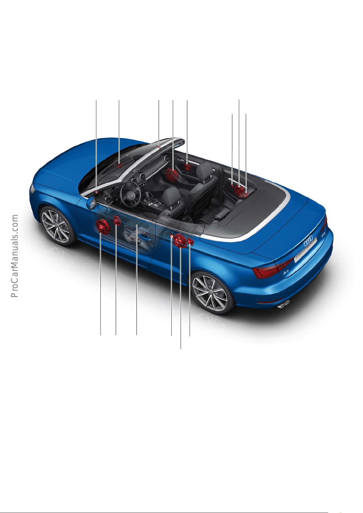
Bang & Olufsen Sound System
Surround sound is provided by 13 high-performance speakers
including centre speakers and, instead of a subwoofer, two special
Kickbass speakers (bass speakers R17/R15) each delivering 100W
for powerful bass.
R20 R208 R22
R23 R104
The speakers are driven through an external 13-channel amplifier
(digital sound package control unit J525) with a total power output
of 625W.
R17
R106
R16
Key:
J525 Digital sound package control unit
R14 Treble loudspeaker, rear left
R15 Bass loudspeaker, rear left
R16 Treble loudspeaker, rear right
R17 Bass loudspeaker, rear right
R20 Treble loudspeaker, front left
R21 Bass loudspeaker, front left
R22 Treble loudspeaker, front right
R23 Bass loudspeaker, front right
R103 Mid-range loudspeaker, front left
R104 Mid-range loudspeaker, front right
R105 Mid-range loudspeaker, left
R106 Mid-range loudspeaker, right
R208 Centre speaker
R103 J525R21
R14
R105
R15
623_100
69
Page 70
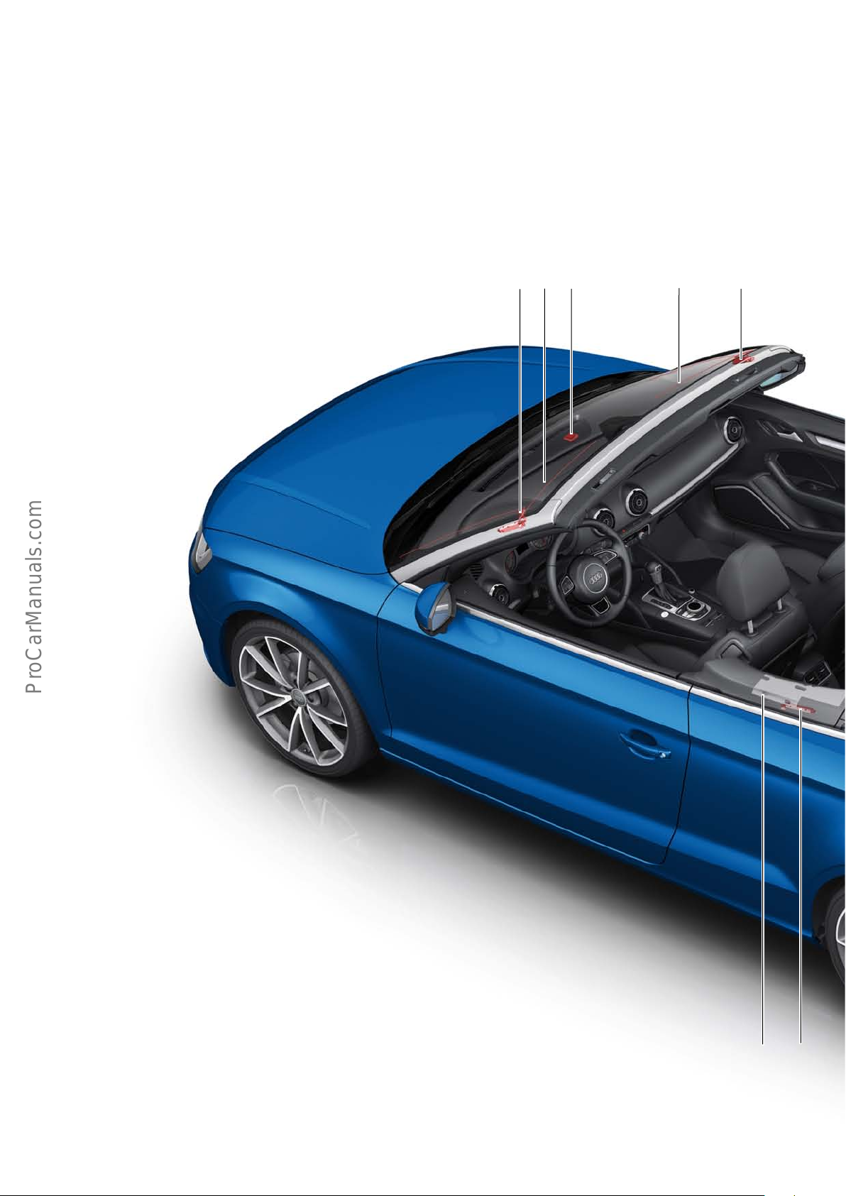
Aerial system
The aerials in the Audi A3 Cabriolet ’14 are chiefly fitted in the
door shoulder as film aerials.
To ensure optimal AM reception when the convertible top is open
and closed, two aerials for AM reception are fitted in the Audi A3
Cabriolet ’14.
The AM1 aerial is integrated in door shoulder, while aerial AM2
R11 is built into the convertible top.
When the convertible top is closed, the signals from the convertible top aerial and aerial amplifier R111 are combined with the
signal from aerial amplifier R24 to give better reception. If the
convertible top is open, only aerial amplifier R24 provides a signal.
If a TV tuner is fitted, its aerials are integrated into the windscreen
at the top.
R83 R56 R50 R82
R55
Key:
R11 AM2 aerial
R24 AM1/FM1 aerial amplifier
R50 GPS aerial
R55 TV1 aerial
R56 TV2 aerial
R65 GSM telephone aerial
R78 TV tuner
R82 DAB/TV1 aerial amplifier
R83 TV2 aerial amplifier
R111 AM2 aerial amplifier
R112 FM2/TV3 aerial amplifier
R172 SDARS aerial
R183 FM2 film aerial 2 R183
R205 LTE aerial 1
R248 AM1/FM1 film aerial 1
R267 LTE aerial 2
R183
R112
70
Page 71
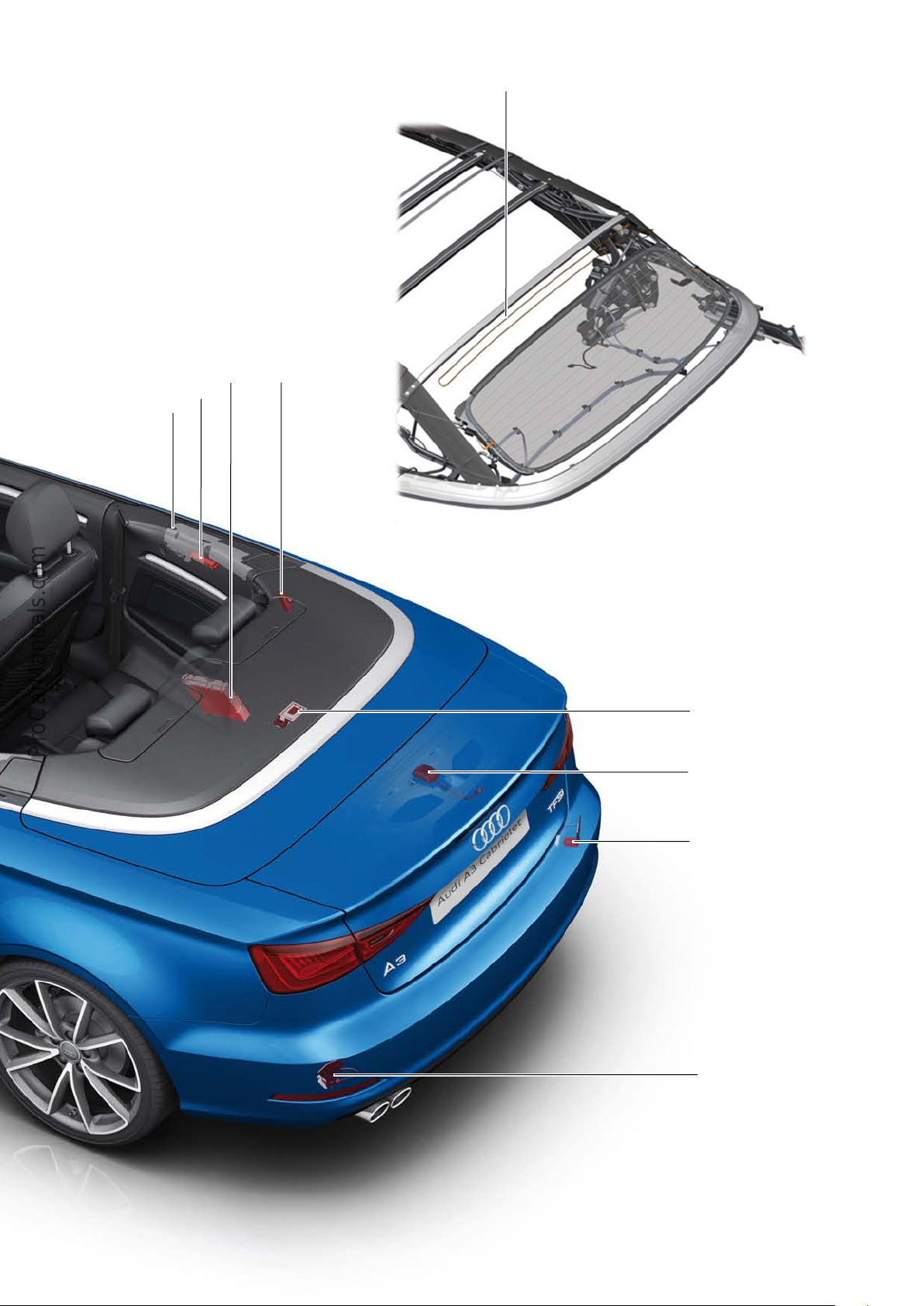
R11
R24
R248
R111R78
623_102
R65
R172
623_101
R267
R205
71
Page 72
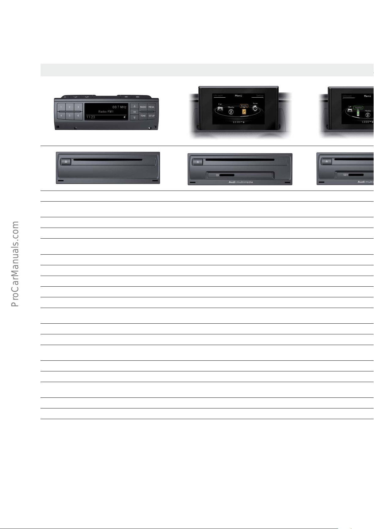
Overview of versions
The following table shows the main equipment features and optional equipment.
Audi Radio (Europe only) MMI Radio MMI Radio with Connectivity Package MMI Radio with Navigation Package MMI Navigation plus
Standard equipment
2.5“ monochrome display with
270x94pixel resolution
5.8“ TFT colour monitor with
400x240pixel resolution
5.8“ TFT colour monitor with
400x240pixel resolution
Prewired for navigation 2D navigation system with SD card 3D hard drive navigation system
AM/FM radio with phase diversity AM/FM radio with phase diversity AM/FM radio with phase diversity and TMC tuner AM/FM radio with phase diversity and TMC tuner
Car settings via Setup Car menu Car menu Car menu Car menu
CD drive (MP3, WMA) CD drive (MP3, WMA, AAC*) CD drive (MP3, AAC, WMA) CD drive (MP3, AAC, WMA) DVD drive (audio/video, MP3, AAC, WMA, MPEG4)
AUX In socket AUX In socket Audi music interface (UE7) Audi music interface (UE7) Audi music interface (UE7)
Basic sound system (2x20watts)
(8RE)
Optional equipment
Basic Plus Sound System (4 x 20 watts) (8RM)
(country-dependent)
Single SD card reader Twin SD card readers Twin SD card readers Twin SD card readers
Basic Plus Sound System (4 x 20 watts) (8RM)
Bluetooth interface for HFP and A2DP (9ZX)
Audi music interface (UE7)
Audi Phone Box for HFP and A2DP (9ZE) Audi Phone Box (9ZE)
DAB or SDARS digital radio (QV3)
Audi Sound System (9VD) Audi Sound System (9VD) Audi Sound System (9VD) Audi Sound System (9VD)
Basic Plus Sound System (4 x 20 watts) (8RM) Basic Plus Sound System (4 x 20 watts) (8RM) Basic Plus Sound System (4 x 20 watts) (8RM)
Bluetooth interface for HFP and A2DP (9ZX) Bluetooth interface for HFP and A2DP (9ZX) Bluetooth interface for HFP and A2DP (9ZX)
DAB or SDARS digital radio (QV3) DAB or SDARS digital radio (QV3) DAB or SDARS digital radio (QV3)
Bang & Olufsen Sound System (9VS) Bang & Olufsen Sound System (9VS) Bang & Olufsen Sound System (9VS)
72
* The MMI Radio can only play back AAC files if optional equipment is fitted.
If an Audi A3 is fitted with Audi connect (9ZK) together with Audi Phone Box (9ZE), the resultant new PR No. is 9ZC.
Page 73
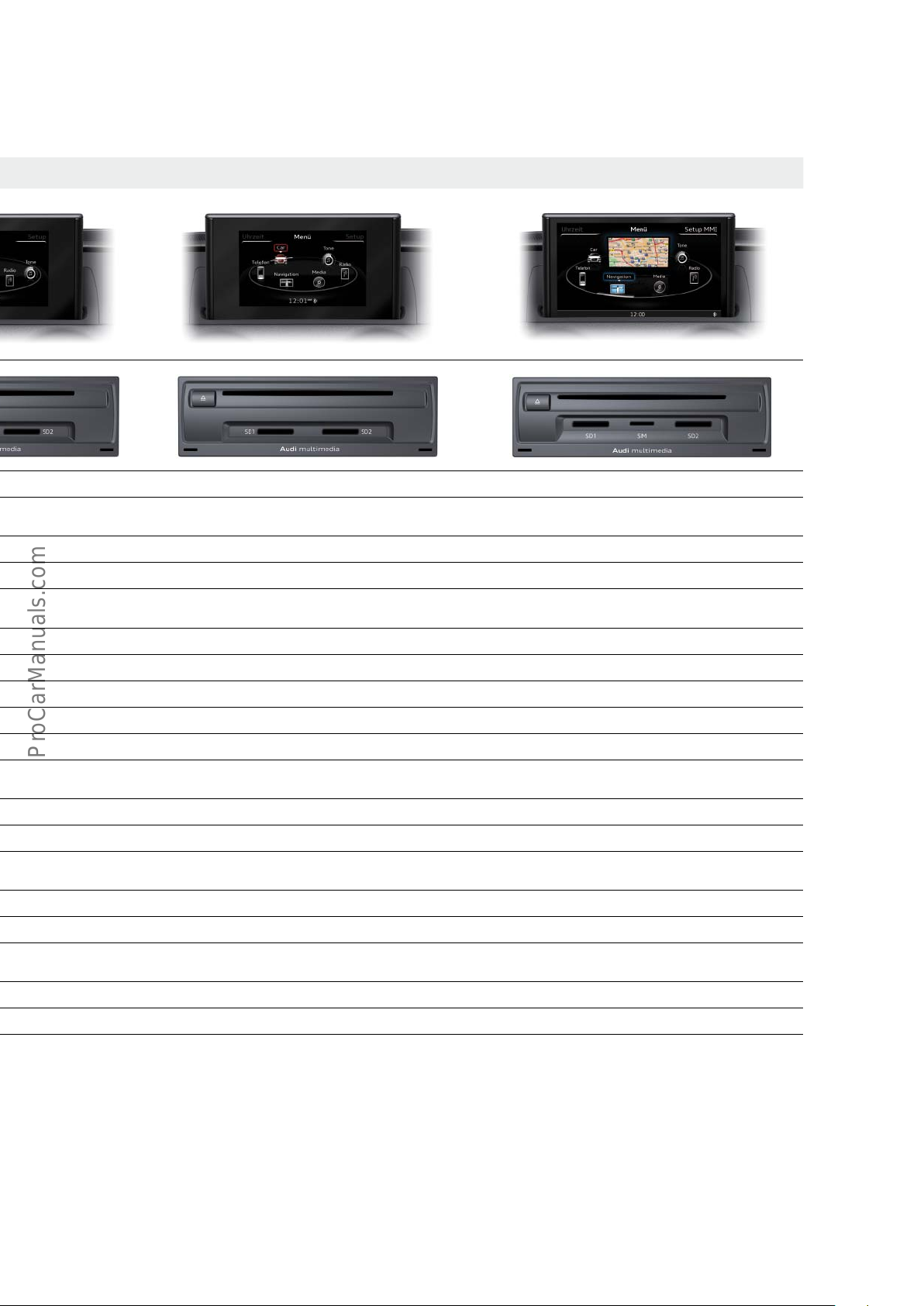
5.8“ TFT colour monitor with
400x240pixel resolution
Basic Plus Sound System (4 x 20 watts) (8RM) Basic Plus Sound System (4 x 20 watts) (8RM)
Audi Phone Box (9ZE) Audi Phone Box (9ZE)
7.0“ TFT colour monitor with
800x480pixel resolution
MMI touch
AM/FM radio with phase diversity and background
tuner
Jukebox with approx. 11GB of memory
Audi connect (9ZK)
DAB or SDARS digital radio (QV3) DAB or SDARS digital radio (QV3)
73
Page 74
Service
Inspection and maintenance
The following service intervals are displayed:
• Oil change service
• Mileage-based service events
• Time-based service events
Example of a service interval display in the MMI
Flexible service event
Mileage-based
service event
Time-based
service event
Next oil change:
--/--
Next inspection:
in 30,000 km / 640 days
CAR - Systems
In new vehicles, the next oil change due box (flexible servicing
event) is initially blank. This interval has to be computed from the
driving profile and engine load and is not displayed until approx.
500 km have been covered. The display "Oil change due" then
switches to "Next oil change".
Overview of maintenance intervals for vehicles in Europe
Car
Service intervals
Handbook
623_099
The value in the mileage-based servicing events box is now 30,000
km for new vehicles and is decremented in increments of 100 km.
The value in the field for the time-based servicing events is now
730 days (2 years) for new vehicles and is updated on a daily basis
(starting at a total mileage of approx. 500 km).
1.6l TDI 2.0l TDI 1.4l TFSI 1.8l TFSI 2.0l TFSI
Oil change between 15,000 km / 1 year and 30,000 km / 2 years
Inspection 30,000 km / 2 years 30,000 km / 2 years 30,000 km / 2 years 30,000 km / 2 years 30,000 km / 2 years
Pollen filter 30,000 km / 2 years 30,000 km / 2 years 30,000 km / 2 years 30,000 km / 2 years 30,000 km / 2 years
Air filter 90,000km 90,000km 90,000km 90,000km 90,000km
Spark plugs — — 60,000 km / 6 years 90,000 km / 6 years 90,000 km / 6 years
Fuel filter 90,000km 90,000km — — —
Timing gear 210,000 km
3)
210,000 km
3)
210,000 km
3)
Chain (lifetime) Chain (lifetime)
Brake fluid Change after 3, 5, ... years
1)
Haldex oil change
Gear oil change
1)
quattro
2)
S-tronic
3)
Replace toothed belt
2)
— 3 years — 3 years 3 years
— 60,000km —
60,000km
quattro only
60,000km
Note
The specifications in the current service literature always apply.
74
Page 75
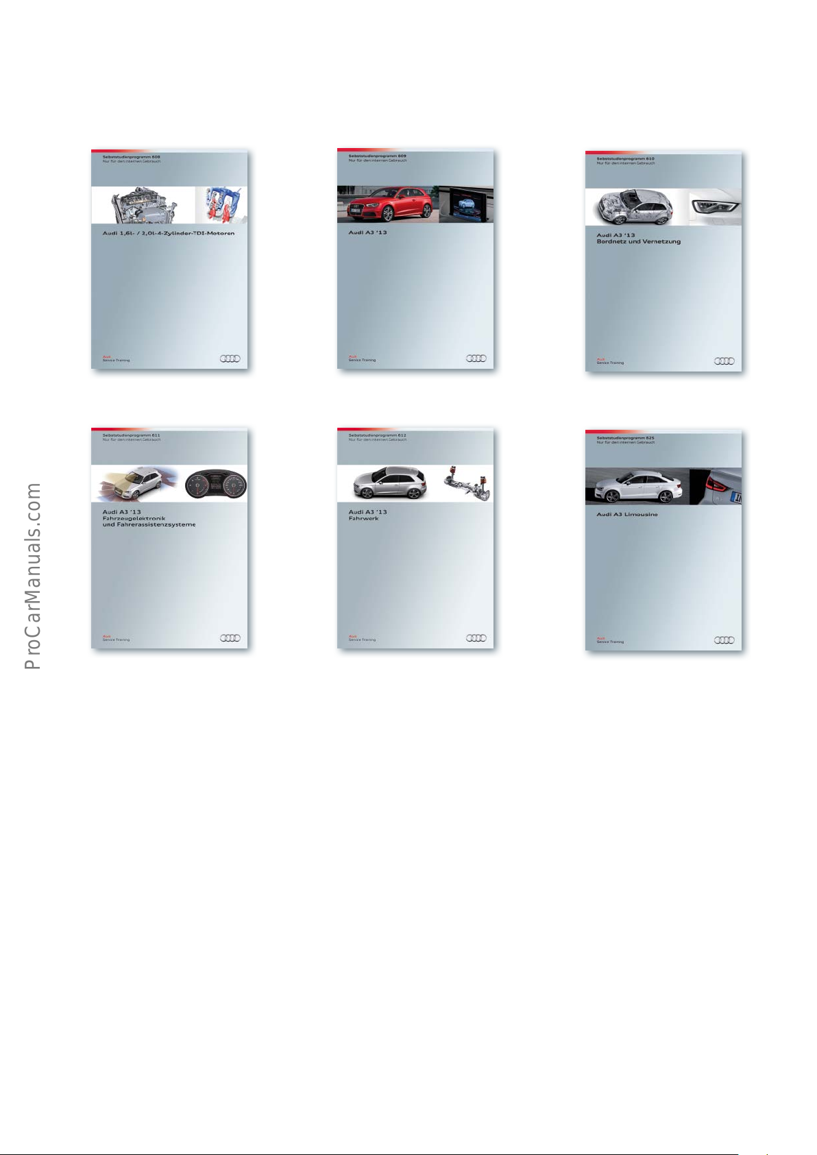
Self Study Programmes
For further information about the technology in the AudiA3 ’13, refer to the following Self Study Programmes.
SSP 608 Audi1.6l/2.0l 4-cylinder TDI engines, order number: A12.5S00.92.20
SSP 609 AudiA3 ’13, order number: A12.5S00.93.20
SSP 610 AudiA3 ’13 onboard power supply and networking, order number: A12.5S00.94.20
SSP 611 AudiA3 ’13 vehicle electronics and driver assistance systems, order number: A12.5S00.95.20
SSP 612 AudiA3 ’13 suspension, order number: A12.5S00.96.20
SSP 625 AudiA3 saloon, order number: A13.5S01.09.20
75
Page 76

Audi
Vorsprung durch Technik
623
All rights reserved.
Technical specifications are subject to
change.
Copyright
AUDI AG
I/VK-35
[email protected]
AUDI AG
D-85045 Ingolstadt
Technical status 10/13
Printed in Germany
A13.5S01.07.20
 Loading...