

Audi 4.2-liter V8 FSI Service Training
Self-Study Program 921603
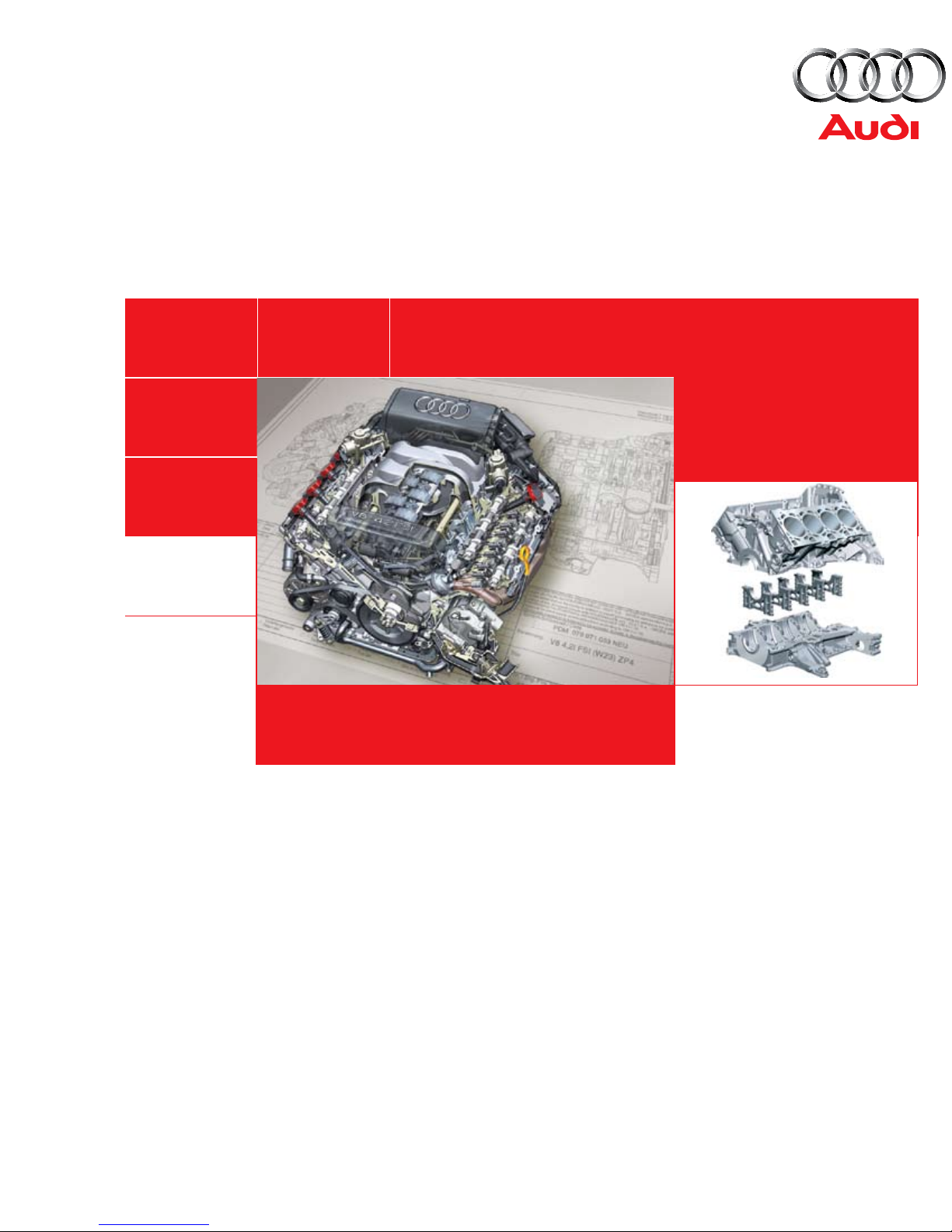
Audi 4.2-liter V8 FSI Engine
Service Training

Audi of America, Inc.
Service Training
Printed in U.S.A.
Printed 07/2006
Course Number 921603
©2006 Audi of America, Inc.
All rights reserved. All information contained in this manual is
based on the latest information available at the time of printing
and is subject to the copyright and other intellectual property
rights of Audi of America, Inc., its affiliated companies and its
licensors. All rights are reserved to make changes at any time
without notice. No part of this document may be reproduced,
stored in a retrieval system, or transmitted in any form or by
any means, electronic, mechanical, photocopying, recording or
otherwise, nor may these materials be modified or reposted to
other sites without the prior expressed written permission of
the publisher.
All requests for permission to copy and redistribute
information should be referred to Audi of America, Inc.
Always check Technical Bulletins and the latest electronic
repair information for information that may supersede any
information included in this booklet.
Trademarks: All brand names and product names used in
this manual are trade names, service marks, trademarks, or
registered trademarks; and are the property of their respective
owners.

Table of Contents
Introduction . . . . . . . . . . . . . . . . . . . . . . . . . . . . . . . . . . . . . . . 1
Engine Mechanical . . . . . . . . . . . . . . . . . . . . . . . . . . . . . . . . . 5
Oil Circulation System . . . . . . . . . . . . . . . . . . . . . . . . . . . . .14
Cooling System . . . . . . . . . . . . . . . . . . . . . . . . . . . . . . . . . . .18
Air Circulation System . . . . . . . . . . . . . . . . . . . . . . . . . . . . .20
Fuel System . . . . . . . . . . . . . . . . . . . . . . . . . . . . . . . . . . . . . .26
Exhaust System . . . . . . . . . . . . . . . . . . . . . . . . . . . . . . . . . . .28
Engine Management . . . . . . . . . . . . . . . . . . . . . . . . . . . . . . .32
Knowledge Assessment . . . . . . . . . . . . . . . . . . . . . . . . . . .43
The Self-Study Program provides introductory information regarding the design
and function of new models, automotive components or technologies.
The Self-Study Program is not a Repair Manual!
All values given are intended as a guideline only and refer
to the software version valid at the time of publication of the SSP.
For maintenance and repair work, always refer to the current technical literature.
Reference Note
i

ii
Introduction
The first member of the current Audi V family of engines was the 3.2-liter V6 FSI engine.
Special features of the Audi V-engine family are the 90-degree angle between the cylinder banks and the 90 mm spacing
between the cylinders.
The 4.2-liter V8 FSI engine is also a member of this family.
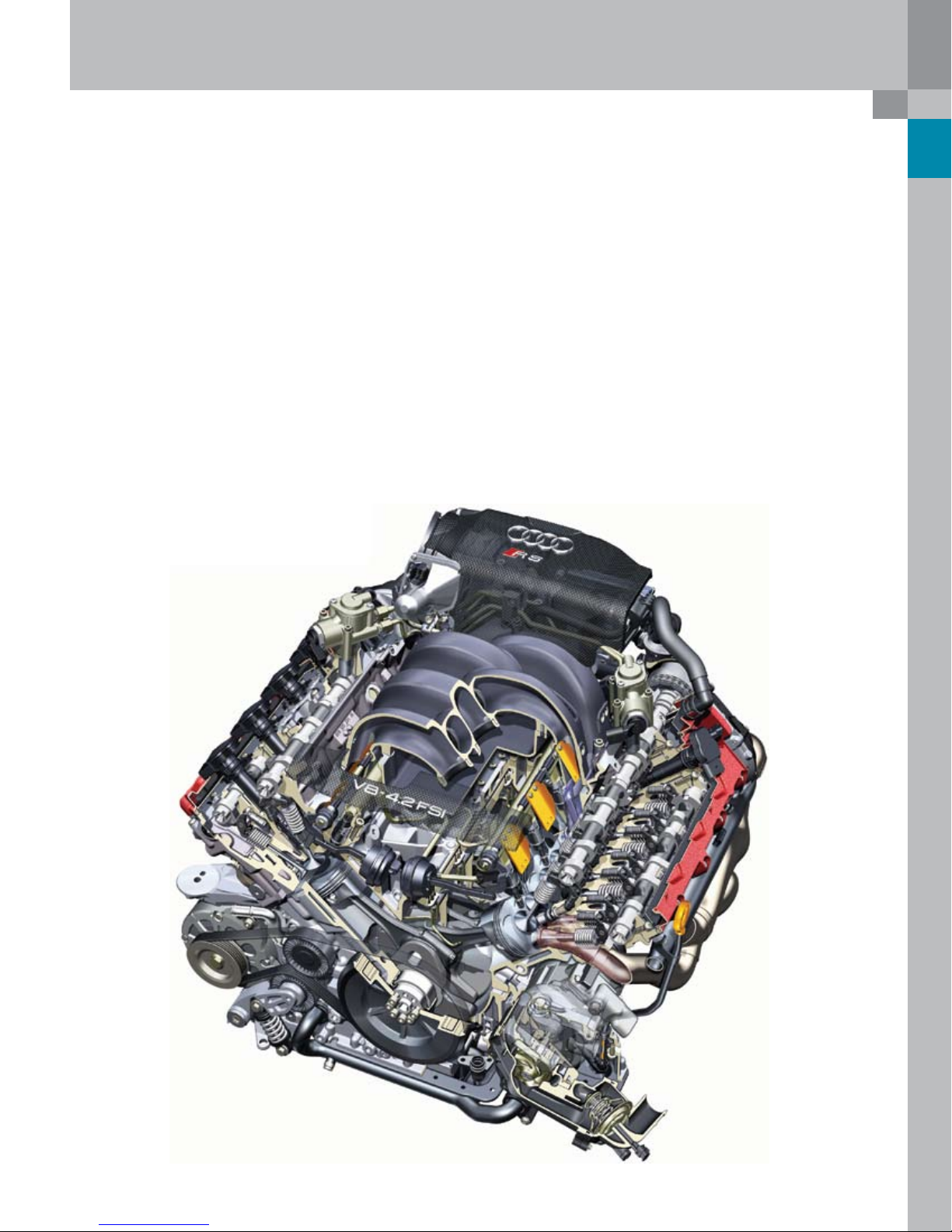
It is available in two versions – a comfort-oriented version (used for the first time in the Audi Q7) and a sporty high-revving
version for the new RS4. A 5.2L V10 FSI will also be available in the near future.
RS4 4.2L V8 FSI High-revving Engine
377_045
1
Introduction
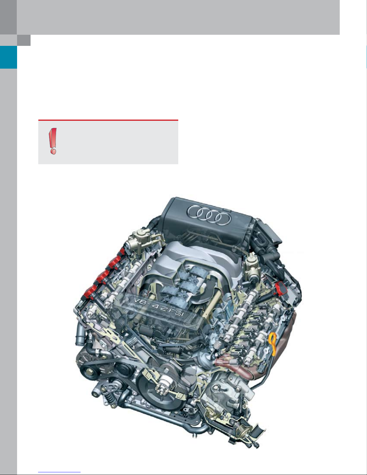
The 4.2-liter V8 FSI engine is supplied in the new Audi Q7
and RS4. In the future, the engine will be used in the Audi
A6 and A8.
Note:
The technical descriptions of this engine
refer mainly to the 4.2L V8 FSI engine in the
Audi Q7 and the high-revving engine in the
Audi RS4.
Audi Q7 4.2L V8 FSI Engine
The following main objectives were set for the
development of the Audi Q7 engine:
High specific engine power:
–
350 bhp out of 4.2 liters (15 bhp more than MPI
●
engines)
High torque: 325 lb. ft. out of 4.2 liters
–
Reduction of fuel consumption by approximately 5 %
–
(at 2000 rpm and 2 bar)
Short and compact design
–
Modular engine concept based on the V6 FSI engine
–
for V8 and V10 FSI
High idling quality
–
High standard of comfort with regard to acoustics and
–
running quality
Low engine weight
–
Off-road capability of Audi Q7 engine
–
2
377_003
Technical Features
Introduction
Fuel Straight Injection
–
Roller cam rocker arms with hydraulic lifters
–
Chain drives for camshafts and accessories
–
Variable camshaft adjustment for intake and exhaust
–
camshafts
Two-stage magnesium variable inlet manifold with
–
integrated tumble flap (not fitted in RS4)
Drive-by-wire throttle control
–
For compliance with exhaust emission standards
●
LEV II
RS4 4.2L V8 FSI Engine
The main technical differences between the base engine
and the high-revving engine lie in the following:
Crankshaft/connecting rods/pistons
–
Timing gear
–
Cylinder head
–
Oil supply
–
Engine cooling
–
Intake path
–
Exhaust system
–
Engine management
–
For an exact description of the differences, please refer to
the relevant sections in this SSP.
377_002
3
Introduction
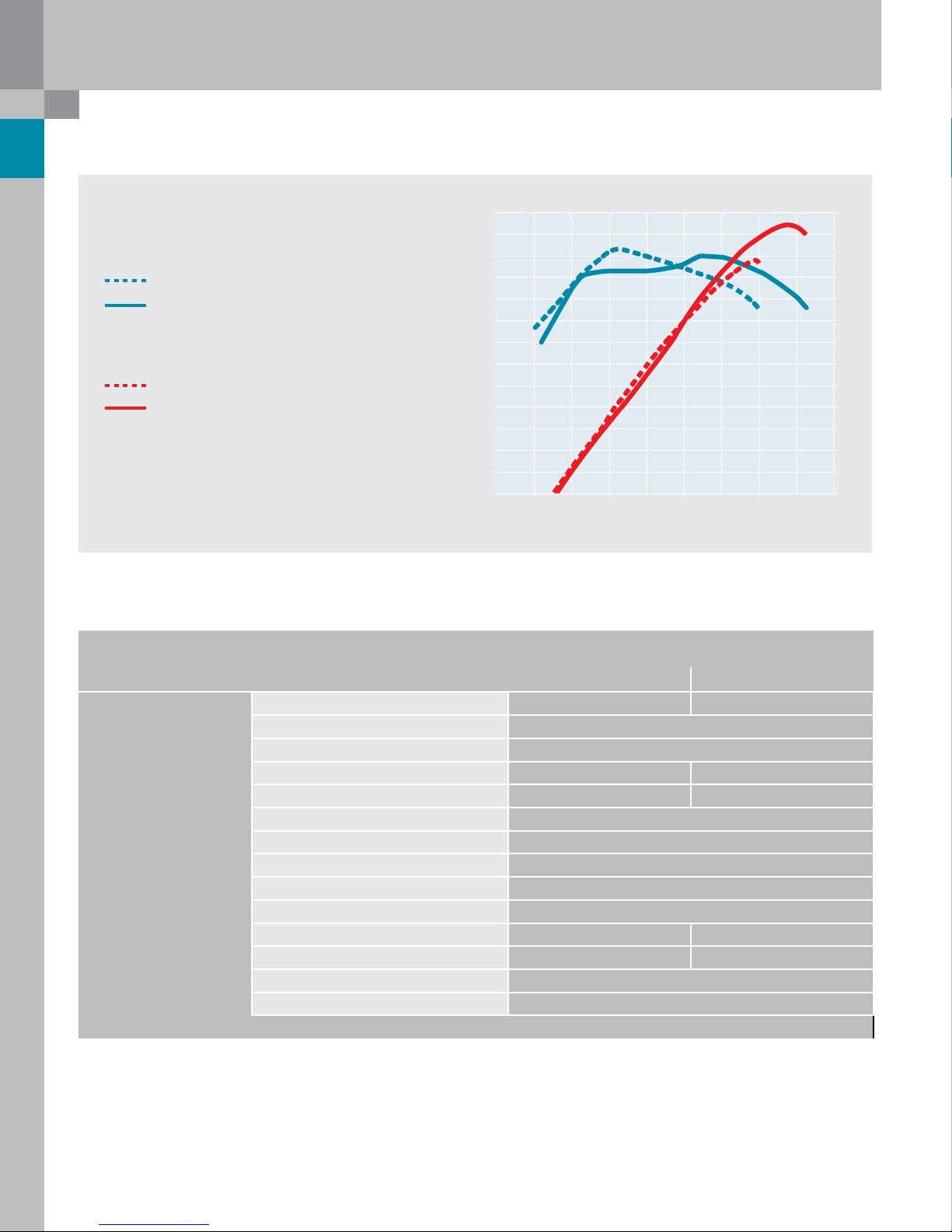
215
268
322
375
429
107
HP
lb ft
340
221
280
310
20000
5000
7000 9000
Torque/Power Curve
Maximum Torque in lb ft
V8 FSI Basic Engine in Audi Q7
V8 FSI High-revving Engine in RS4
Maximum Power Output in Horsepower (HP)
V8 FSI Basic Engine in Audi Q7
V8 FSI High-revving Engine in RS4
Engine Speed in RPM
Specifications
Audi Q7 RS4
Engine Code BAR BNS
Type of Engine V8 90° V angle 4V FSI
Displacement in cm
Maximum Power Output in bhp 350 @ 6800 rpm 420 @ 7800 rpm
Maximum Torque in lbft 325 @ 3500 rpm 317 @5500 rpm
Valves per Cylinder 4
Bore in mm (in) 84.5 (3.33)
Stroke in mm (in) 92.8 (3.66)
Compression Ratio 12.5/-0.4 : 1
Firing Order 1–5–4–8–6–3–7–2
Engine Weight in lbs approximately 437* approximately 467**
Engine Management Bosch MED 9.1.1 Bosch 2x MED 9.1
Fuel Grade 98 / 95 RON (91 octane)
Exhaust Emission Standard LEV II
3
4163
4
* with automatic transmission
** manual transmission including clutch and dual-mass flywheel
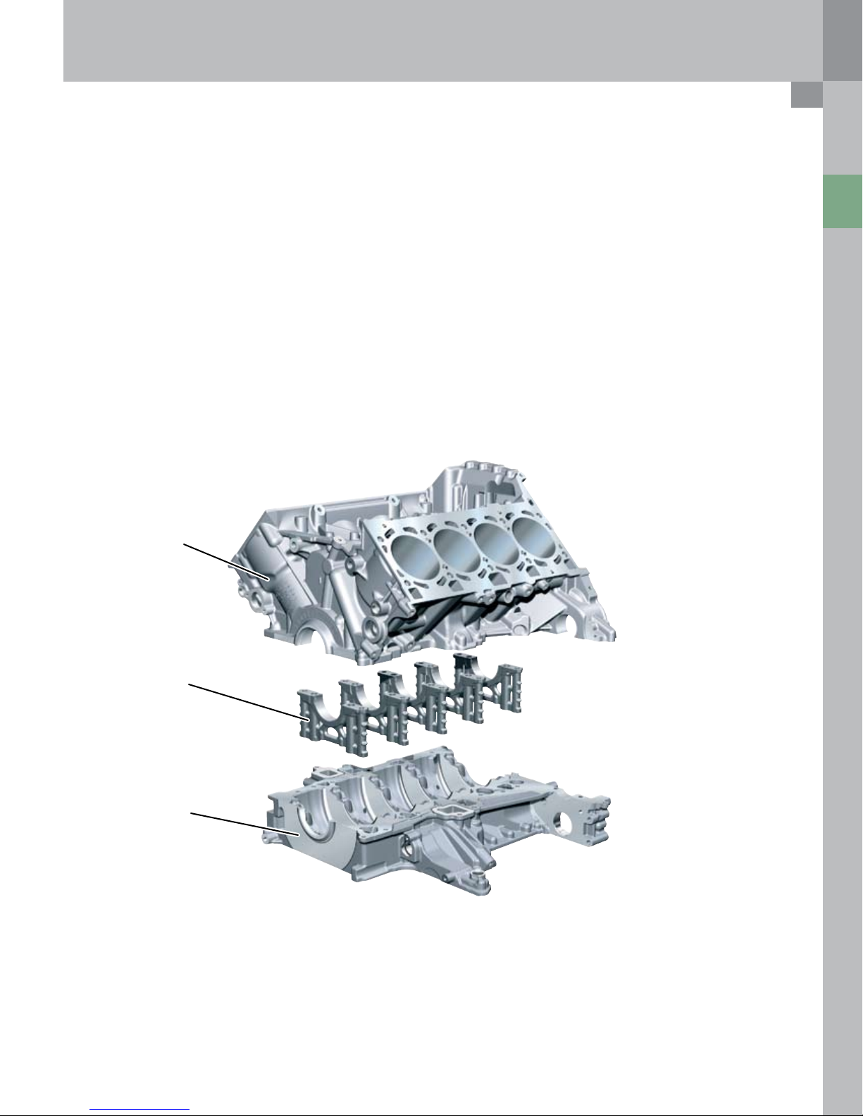
Cylinder Block
Engine Mechanical
The cylinder crankcase has a closed-deck design, which is
stronger than the open-deck design.
In an open-deck cylinder block, the water jacket for
cooling the cylinders is open at the top. The cylinder
crankcase is made of a low-pressure gravity diecast
aluminum-silicon alloy, is hypereutectic* and has a
silicon content of 17 % (AlSi17Cu4Mg).
The cylinder crankcase underwent special heat
treatment to increase its strength. The cylinder liners are
mechanically stripped.
The cylinder crankcase of the high-revving engine was
machined to higher specifications due to the higher
stresses in this component. To minimize warping of the
cylinder manifolds, the crankcase is honed under stress.
For this purpose, a honing template is attached to the
crankcase before the honing process in order to simulate
the warping of the bolted-on cylinder manifold.
Cylinder Block
Top Section
*Aluminum alloys are classed as hypoeutectic or
hypereutectic, depending on their silicon content.
“Alusil” has a hypereutectic silicon content of 16 to 18 %
so that primary silicon is precipitated on solidification of
the molten metal.
A multistage honing process is applied. The silicon grains
in the cylinder bores in the form of microscopically small,
very hard particles are stripped to give the necessary
wear resistance of the cylinder surfaces for the piston
and piston rings.
Cylinder spacing: 90 mm
–
Cylinder bank offset: 18.5 mm
–
Overall engine length: 464 mm
–
Cylinder block height: 228 mm
–
Press-fit
Main Bearings
Cylinder Block
Bottom Section
The cylinder crankcase lower section (bedplate bearing
cross-member) is made of aluminum with press-fitted
iron main bearing covers made of grade 50 nodular cast
iron. It is centered using centering pins, sealed with
liquid sealant and bolted to the cylinder crankcase.
The main bearing is symmetric with the center of the
main bearing, attached by four bolts. The bedplate type
design provides high stability. The bedplate has the same
stabilizing effect as a ladder frame.
5
Engine Mechanical
Crankshaft/Connecting Rods/
Pistons
Crankshaft
The crankshaft runs on five bearings and is made of highalloy tempered steel (42CrMoS4). It is 90° cranked and
has no connecting rod journal offset.
The vibration damper is a vulcanized single-mass damper
with unbalance.
Main bearing diameter: 65 mm
–
Main bearing width: 18.5 mm
–
–
Big-end bearing diameter: 54 mm
–
Big-end bearing width: 15.25 mm
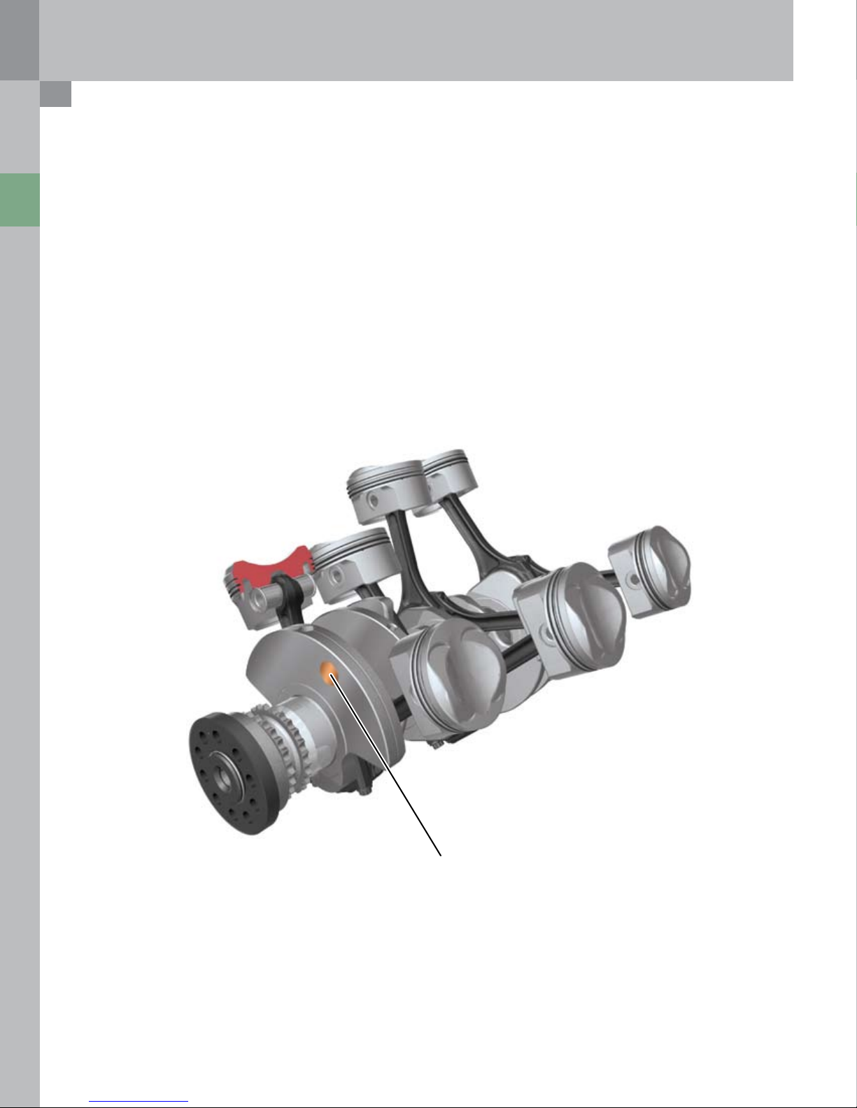
RS4 Crankshaft
Modifications to High-revving Engine
At very high engine speeds, axial vibration occurs due to
the unbalance in the single-mass damper. This can cause
the crankshaft to break.
To avoid this vibration, a dual-mass damper without
unbalance is employed in the high-revving engine.
To compensate for unwanted engine vibration, heavy
metal inserts are integrated in the first and eighth crank
journals by way of unbalance.
6
377_035
Heavy Metal Inserts
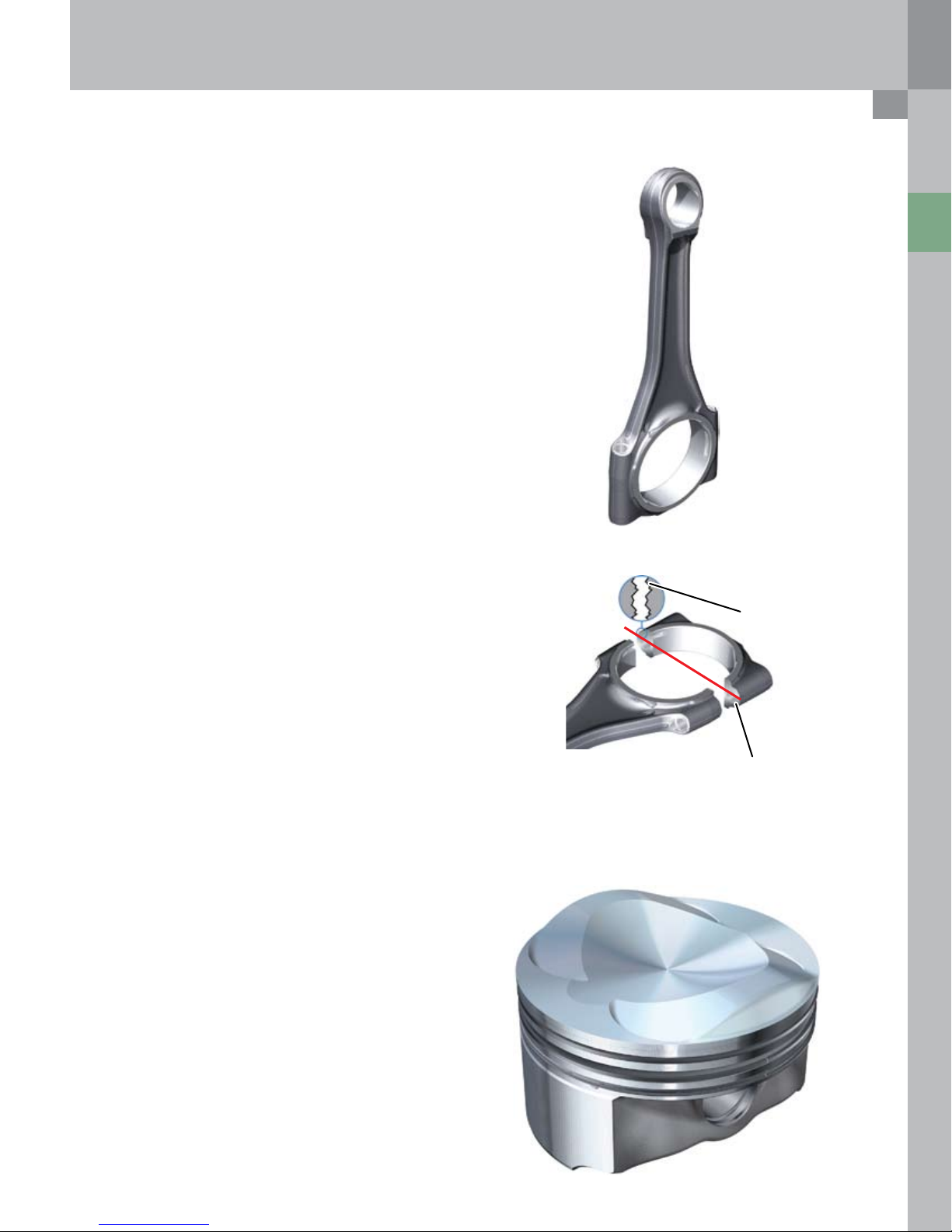
Connecting Rod
Cracked connecting rods made of 36MnVS4 are
used in the basic engine, while the conventionally
split connecting rods in the RS4 engine are made of
34CrNiMo8, for strength.
In addition, the geometry and tolerances of the
connecting rods were reduced on the high revving
version of the 4.2L V8 FSI engine.
Bearing journals diameter: 54 mm
–
Bearing bushings: 1.4 mm thick,
–
15.25 mm wide
–
Length of bushing: 0.20 mm diameter rolled
–
Connecting rod length: 154 mm
Engine Mechanical
Cracking
During the cracking process, the connecting rod is split
at a predetermined breaking point using a special tool.
The resultant unique breaking surface ensures the high
joining precision of the two mating parts.
Piston
For strength reasons, forged pistons with a slightly higher
weight than conventional pistons, are used. Both engines
have the same piston geometry.
377_058
Breaking surface
Predetermined
breaking point
377_062
Piston weight
–
without rings: approximately 290 g (10 oz)
–
Piston pin: 0.20 mm x 0.11.5 mm x 40 mm
377_057
7
Engine Mechanical
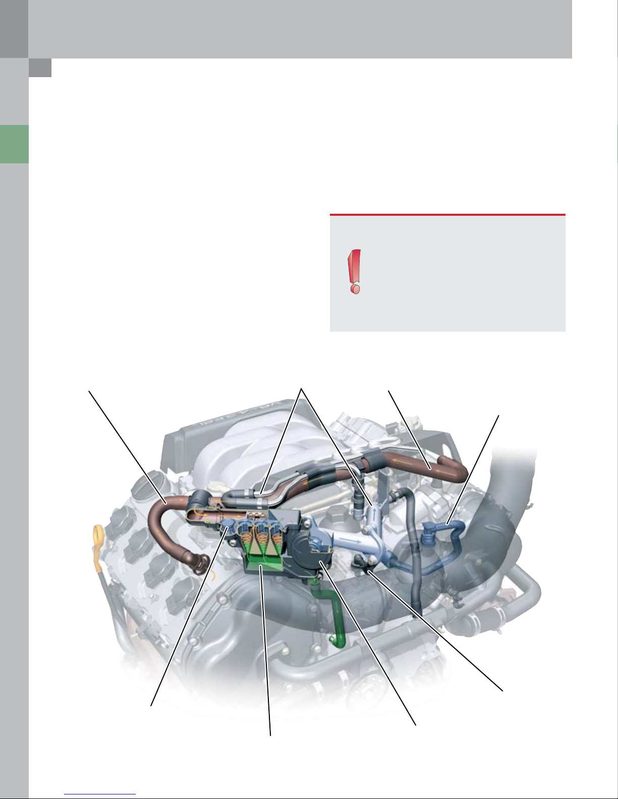
Crankcase Ventilation
The crankcase is ventilated through both cylinder heads.
The valve covers incorporate a large settling space.
This space acts as a gravity-type oil separator. A fine oil
separator is connected to the valve covers by means of
plastic hoses.
A control piston, a bypass valve, a two-stage pressure
limiting valve and an oil drain valve are integrated in the
oil separator housing.
Breather Pipe Heater
After the blow-by gas has passed through the fine
oil separator, the gas flows into the intake manifold
downstream of the throttle valve.
This inlet point is integrated in the coolant circulation
system and heated. This prevents the crankcase breather
from freezing up.
Note:
Modifications after start of production
In both engines, the separated oil flows
into the crankcase through the cover in the
inner V, adjacent the crankcase breather
(no longer through the chain housing).
In the Audi Q7 engine, the crankcase is
vented through a single chamber, i.e.,
via bank 2 only. Better icing protection is
achieved in this way.
Breather Pipe
Bypass Valve
Fine Oil Separator
Pressure Limiting Valve
Crankcase Breather System
377_009
Non-return Valve
(crankcase breather)
8
Engine Mechanical
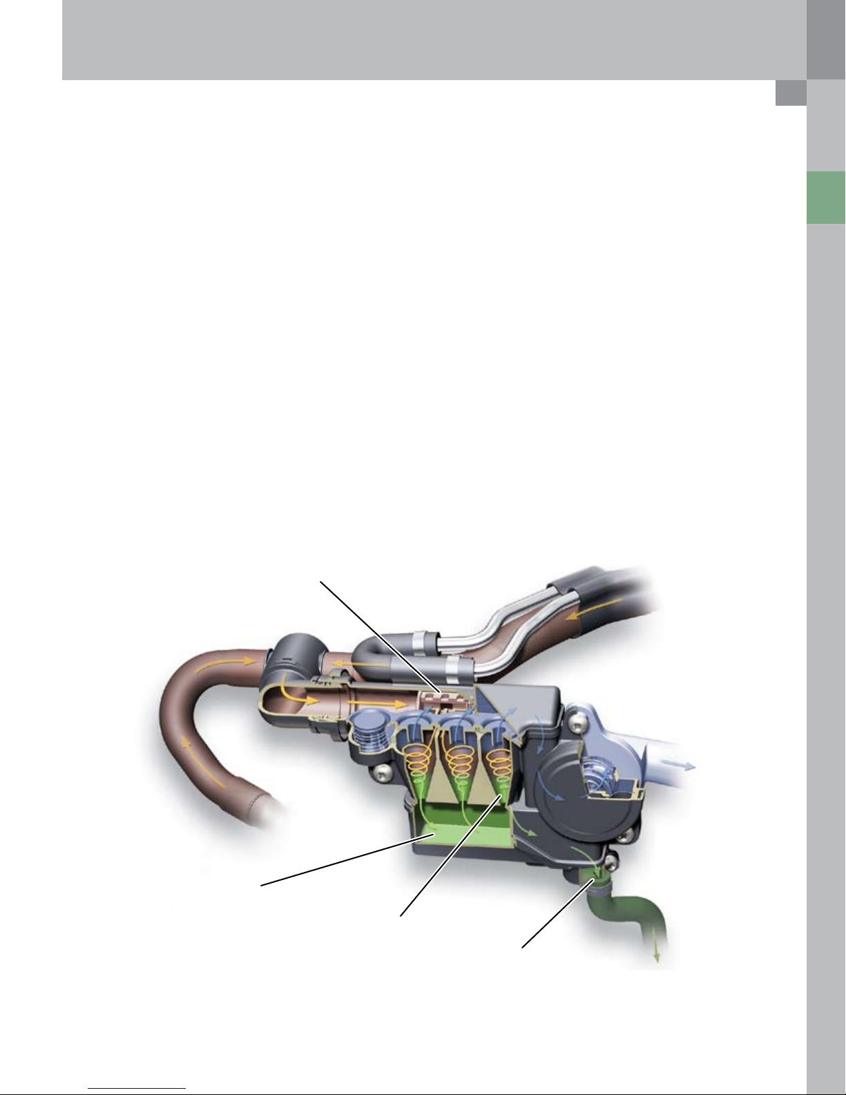
Fine Oil Separator
Blow-by gas volume is dependent on engine load and
RPM. The fine oil (“oil spray”) is separated by means
of a cyclone separator. Cyclone separators have a high
separation efficiency over only a small volumetric range.
For that reason, one, two, or three cyclones of the fine oil
separator operate in parallel, depending on the gas-flow
rate.
The cyclones are released by the control piston. The
displacement of the control piston against its spring
force is dependent on the gas-flow rate. Piston ring
flutter at very high engine RPMs and low engine load can
result in a very high gas-flow rate.
The crankcase internal pressure is set by the two-stage
pressure control valve. The bypass valve, together with
the control piston, ensures that the cyclones operate at
the optimum operating point (if the volumetric flow rate
is too high or too low, it will impair the functioning of the
cyclones).
When the bypass valve opens, a fraction of the blow-by
gas flows to the engine untreated, but the remainder is
optimally treated by the cyclones.
The separated oil is collected in an oil reservoir beneath
the cyclones. The oil cannot drain out of the reservoir
until the oil drain valve is opened. The oil drain valve
is closed as long as the pressure in the crankcase, i.e.,
below the valves, is higher than in the oil separator. The
valve opens automatically due to gravity only at very
low engine RPMs or when the engine is at a standstill,
because the pressure conditions above and below the
valve are in equilibrium.
The crankcase ventilation system also includes the
crankcase breather. Air is extracted downstream of the
air filter and flows through a non-return valve into the
crankcase from above.
The non-return valve is located at the end of the vent
line and is bolted between the two cylinder banks in the
engine block.
A damping chamber is located below the non-return
valve in the engine block. This prevents non-return valve
flutter and eliminates noise.
A restrictor bore connects this chamber to the inner
chamber of the crankcase. It has the task of supplying
only a defined volume of fresh air to the crankcase.
Oil Reservoir
Control Piston
Triple Cyclones
Oil Drain Valve
377_011
9
Engine Mechanical
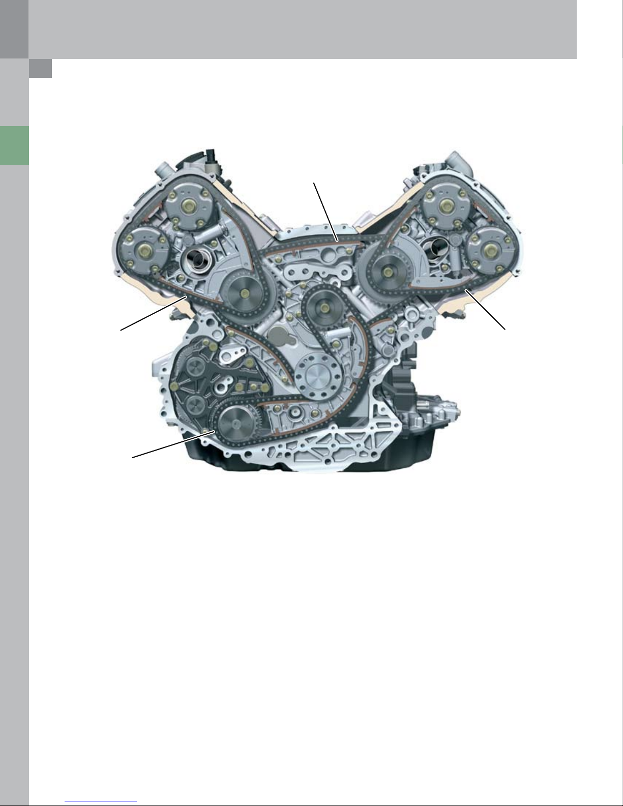
Chain Drives
Audi Q7 4.2L V8 FSI Engine
Chain Drive A
Chain Drive B Chain Drive C
Chain Drive D
The timing gear concept is identical in all Audi V-engine
series.
There are four chain drives arranged in two layers.
Layer 1
Chain drive A drives the camshafts idler gears from
–
the crankshaft
Layer 2
Top drives B and C drive the camshafts from the idler
–
gears
Chain drive D drives the accessory drive module from
–
the crankshaft
Correct chain tension is ensured by hydraulic tensioners.
The chain drive is maintenance-free and designed for
lifetime service.
The two engine types differ in terms of the type of chains
used and the reduction ratios in drives A, B and C. The
load on the roller chains was reduced in the basic engine
version by selecting a greater number of teeth.
10
377_012
Audi Q7
The camshafts in the basic engine are driven by 3/8”
simplex roller chains.
Due to their acoustic advantages, the chains were
developed to meet the high comfort requirements.
In this case, the idler gears have 40 and 24 teeth. The
camshaft sprockets have 30 teeth.
High-revving Engine
3/8“ simplex sleeve-type chains are used here. Their
advantage is their reduced wear and higher stress
resistance at high engine speeds.
In this case the idler gears have 38 and 19 teeth. The
camshaft sprockets have 25 teeth.
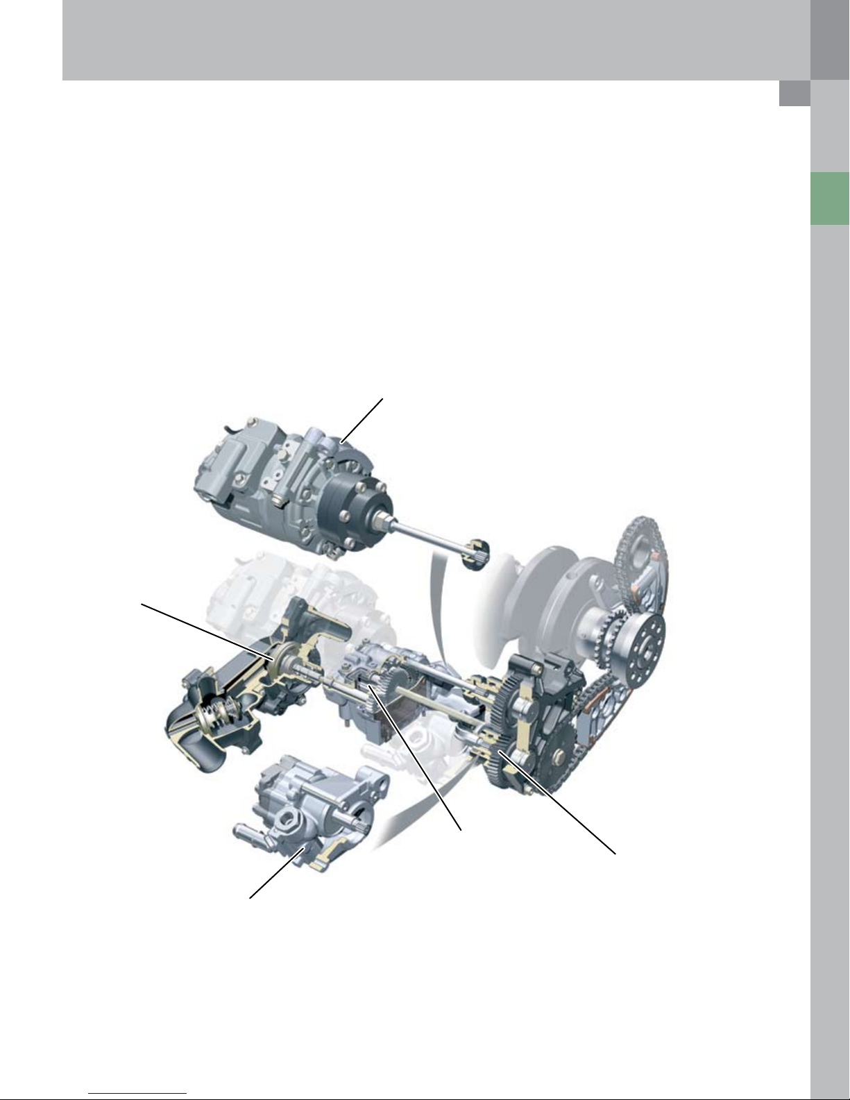
Accessory Drive
The oil pump, water pump, power steering pump and the
compressor are driven by chain drive D.
The chain is driven directly by the crankshaft, deflected
by an idler gear and drives the chain sprocket seated on
the gear module.
Air Conditioner Compressor
Engine Mechanical
Coolant Pump
377_013
Oil Pump
Gear Module
Power Steering Pump
11
 Loading...