

Audi V6 BITURBO, 2.7-litre V6 Biturbo User Manual
Service.
For internal use only
198
All rights reserved. Subject
to change.
AUDI AG
Dept.I/GS-5
D-85045 Ingolstadt
Fax +49.841/89-6367
740.2810.17.20
Technical status: 01/98
Printed in Germany
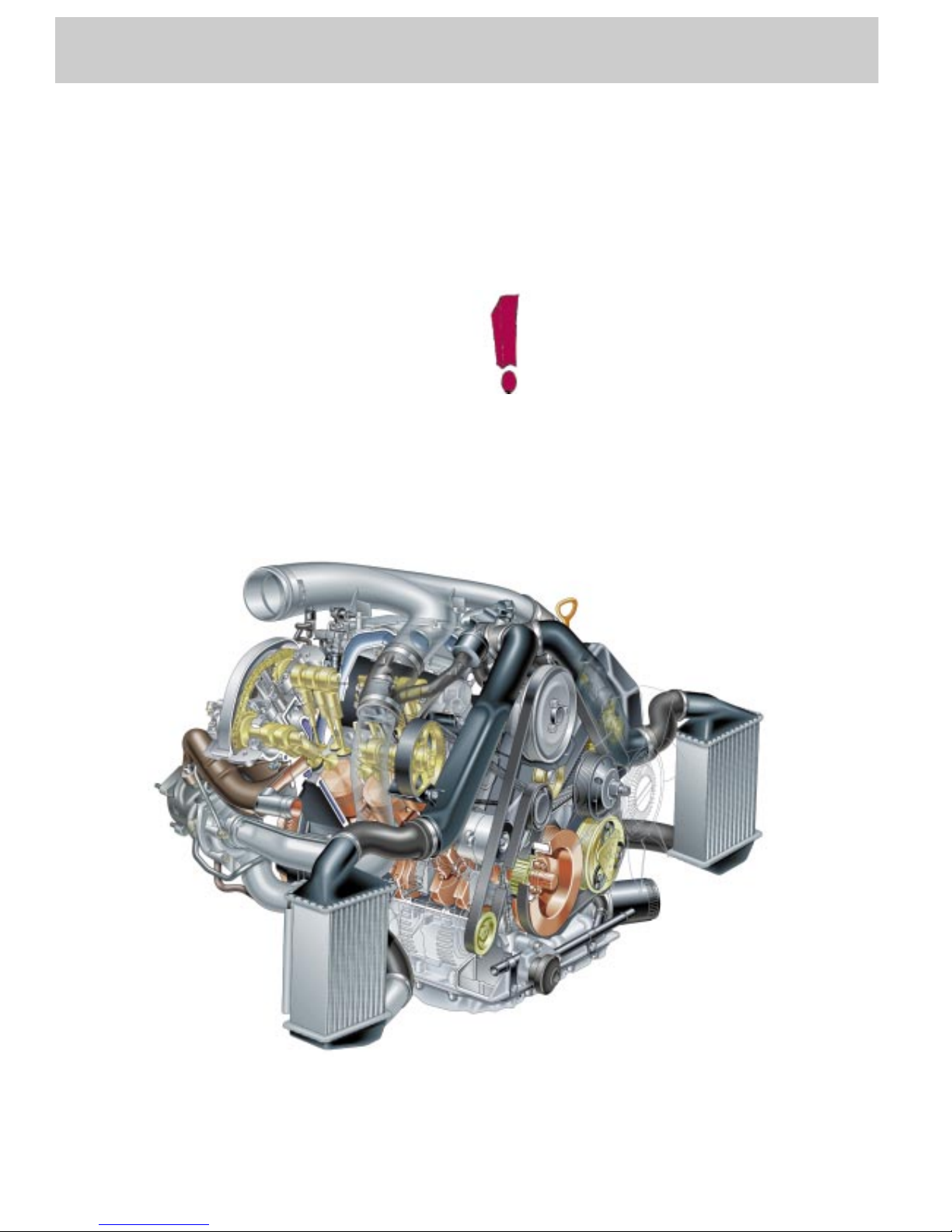
The 2.7-litre V6 Biturbo
Design and Function
Self-study Programme 198
2
The 2.7-litre V6 biturbo .......
Turbocharged engines are already something
of a tradition at AUDI. The task now facing
AUDI’s engineers was to develop a worthy
successor to the 5-cylinder turbocharged
engine.
One of the key development goals for the
turbocharged engine was to achieve a good
level of dynamic response, particularly at the
bottom end of the rev band.
........ a further milestone in engine development by Audi!
The goal of AUDI’s engineers was to realise a
high “basic torque level“ and a torque
characteristic that rises in direct proportion to
engine speed to its peak.
The term “basic torque level“
describes the torque which is
immediately available when the
throttle is opened (e.g. at part
throttle or in overrun).
SSP 198/77

3
This Self-study Programme provides you with information
regarding design and function.
The Self-study Programme is not a Workshop Manual!
Please refer to the Service Literature for all the relevant
maintenance and repair instructions.
Page
Engine .........................................................
Technical data, crankshaft, cylinder head,
camshaft timing, cooling circuit, engine
lubrication, overview of components, air ducting,
charging, exhaust system, pneumatically
controlled systems, charge pressure control, air
divert control in overrun, ACF system, crankcase
breather
4
Motronic ME 7.1..........................................
Subfunctions, system overview
31
Subsystems of the Motronic .....................
Torque-oriented engine management, torqueoriented functional structure, Electronic throttle,
exhaust gas temperature control
33
Sensors .......................................................
Additional sensors of the Motronic
49
Auxiliary signals/interfaces ...................... 57
Functional diagram..................................... 62
Self-diagnosis .............................................
Vehicle diagnosis, test and information system
VAS 5051, test box V.A.G 1598/31
64
Transmission ..............................................
Self-adjusting clutch, gearbox
66
Contents
Important!/Note!
New!
4
Engine
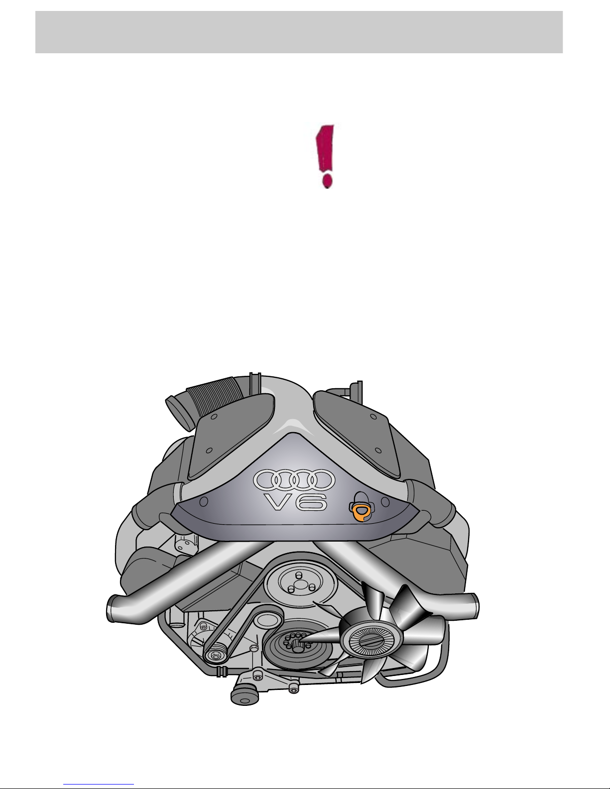
The 2.7-litre V6 biturbo
This engine will also be used in the Audi S4
and Audi A6.
The engine used in the A6 has a comfortoriented setup, which means that it has
different torque and power output.
This effect was principally achieved by
modifying the software configuration of the
engine control unit.
A tuning protective device prevents
the S4 engine control unit being
installed in the A6!
This prevents misuse, which can
result in damage to the drivetrain!
An auxiliary heater is not available
as an option for the S4 and the A6,
due to the constraints on space.
BITURBO
SSP 198/01

5
The technical data
•
Configuration:
V6 engine with 90° V-angle and twin
turbochargers
•
Engine code:
S4: AGB
A6: AJK
•
Output:
S4: 195 kW at 5800 rpm
A6: 169 kW at 5800 rpm
•
Torque:
S4: 400 Nm at 1850 to 3600 rpm
A6: 310 Nm at 1700 to 4600 rpm
•
Maximum speed:
6800 rpm
•
Compression ratio:
9.3 : 1
•
Displacement:
2671 cm
3
•
Bore:
81 mm
•
Stroke:
86.4 mm
•
Weight:
approx. 200 kg
•
Engine management:
Motronic ME 7.1
•
Firing order:
1-4-3-6-2-5
•
Fuel type:
S4: 98/95/91 RON
A6: 95/91 RON
•
Compliant with emission standard:
EU III-D
Figures obtained using 98 RON
unleaded premium fuel to
89/491/EEC.
Figures obtained using 95 RON
unleaded premium fuel to
89/491/EEC.
500
450
400
350
300
250
200
150
100
50
0
200,0
180,0
160,0
140,0
120,0
100,0
80,0
60,0
40,0
20,0
0,0
0 1000 2000 3000 4000 5000 6000 7000
SSP 198/02
Speed [rpm]
Torque [Nm]
Output [kW]
S4
500
450
400
350
300
250
200
150
100
50
0
180,0
160,0
140,0
120,0
100,0
80,0
60,0
40,0
20,0
0,0
0 1000 2000 3000 4000 5000 6000 7000
SSP 198/46
Speed [rpm]
Torque [Nm]
Output [kW]
A6
6
Engine
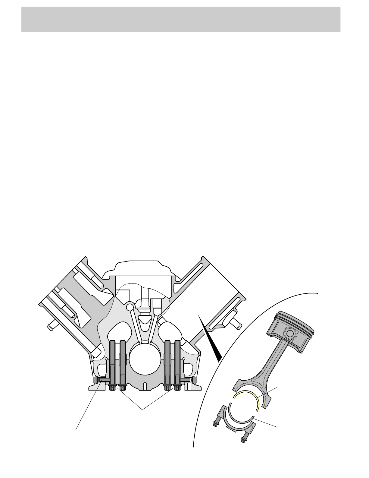
The crankshaft
The crankshaft is identical to that used in the
2.8-litre V6 engine.
The crankshaft bearing caps are attached to
the central crankcase by 4 bolts.
•
The 4-bolt connection reduces the load on
the bearing caps considerably.
The middle two crankshaft bearing caps are
also bolted to the side of the crankcase.
•
The lateral bolted connection helps to
improve acoustics.
The pistons are forged to enable them to
withstand the high loads to which they are
subjected.
Due to the high combustion pressures, a 2material bearing shell is installed on the
connecting rod side. The bearing cap has a 3material bearing shell.
Advantage:
The bearing shell has a high load-bearing
capacity
SSP 198/11
Lateral bolted connection
4-bolt connection
2-material
bearing shell
3-material
bearing shell
7
Cylinder head
The cylinder heads are largely identical to
those used in the V6 naturally aspirated
engine. Common parts are used for both banks
of cylinders.
The mounting position of the right-hand
cylinder head is rotated through an angle of
180° in relation to the left-hand cylinder head.
The timing of the inlet camshafts is enginedependent.
To improve heat dissipation, the exhaust
valves are sodium-filled.
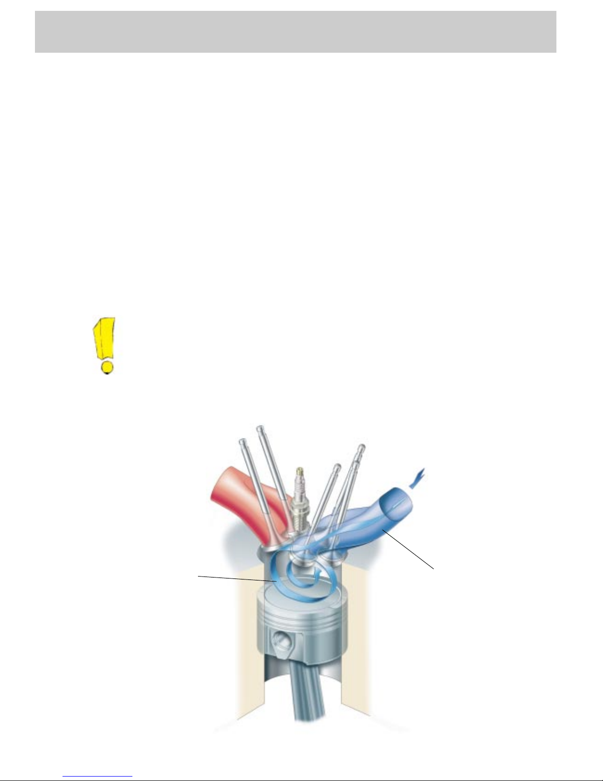
The shape of the inlet duct causes the drawnin air to tumble.
Advantages:
•
A good degree of swirl and high ignitability
fuel-air mixture are achieved
•
The tumble effect allows more efficient
combustion
For a turbocharged engine, the compression
ratio of 9.3 : 1 is high.
Advantage:
•
High ”basic torque level“ and fuel
economy
Tumble duct
In combination with five-valveper-cylinder technology, the inlet
duct is shaped as a so-called
“tumble duct“.
Tumble duct
Tumble effect
SSP 198/78
8
Engine
The variable valve timing
The camshaft timing has been modified
compared to the 2.8-litre V6 engine to meet the
demands of turbocharging technology.
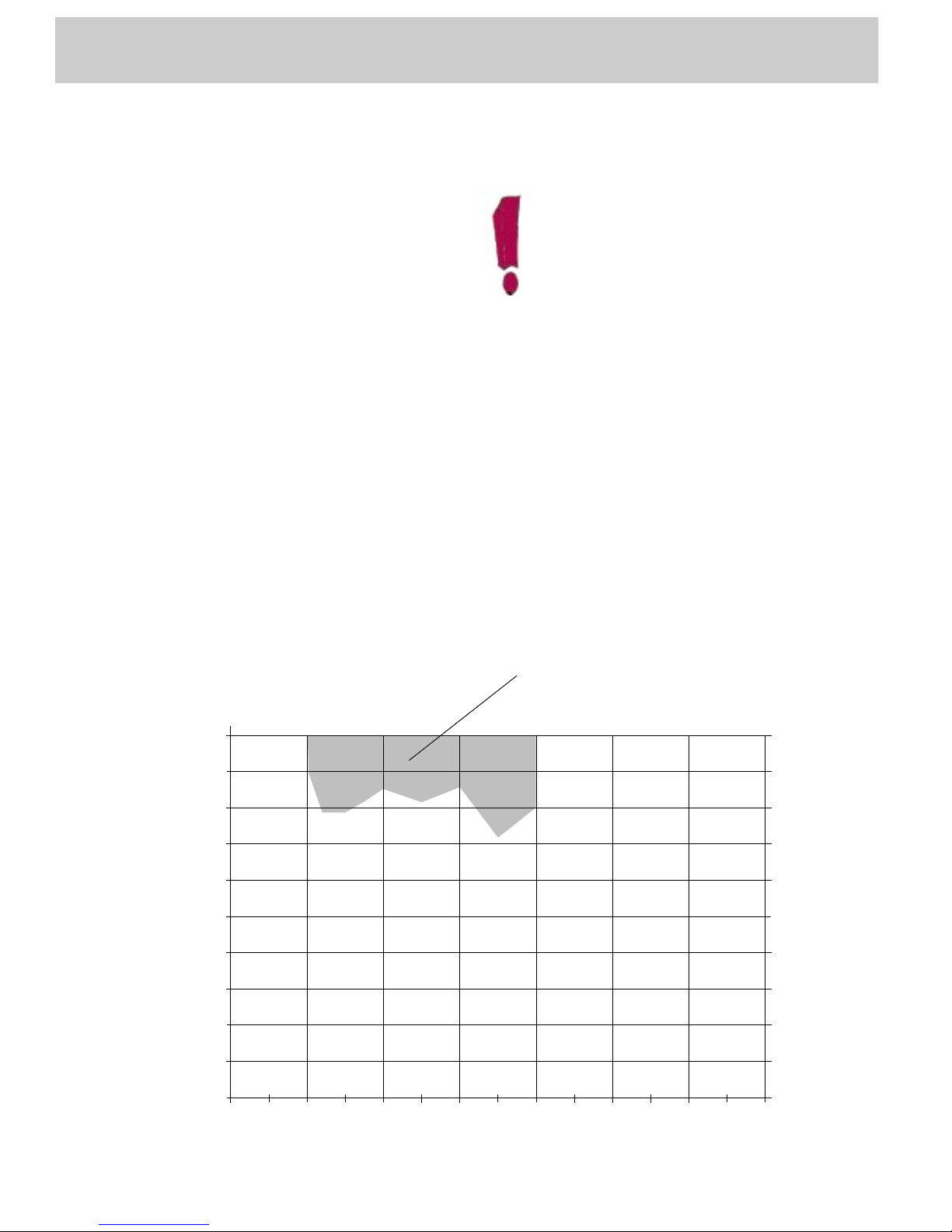
Variable valve timing with an adjustment angle
of 22° is used here for the first time in
turbocharged engines .
Advantage:
•
A torque increase of approx. 10% is
achieved at the bottom and top ends of the
engine speed range.
•
Better emission levels and fuel
consumption figures.
The variable valve timing is activated by the
Motronic by means of camshaft adjustment
valves N205 and N208.
The design and function of the
variable valve timing are already
described in Self-study Programmes
182 and 192.
Activation of the variable valve timing is
dependent on engine load and speed.
In the self-diagnosis, you can find out whether
the variable valve timing is active or not by
reading out the relevant measured value block
(refer to Workshop Manual).
0
0 1000 2000 3000 4000 5000 6000 7000
SSP 198/45
Diagram of variable valve timing
(shown using the 265 bhp engine as an
example)
Engine speed
Engine load in %
Variable valve timing active
= advance position
Full throttle
9
SSP 198/03
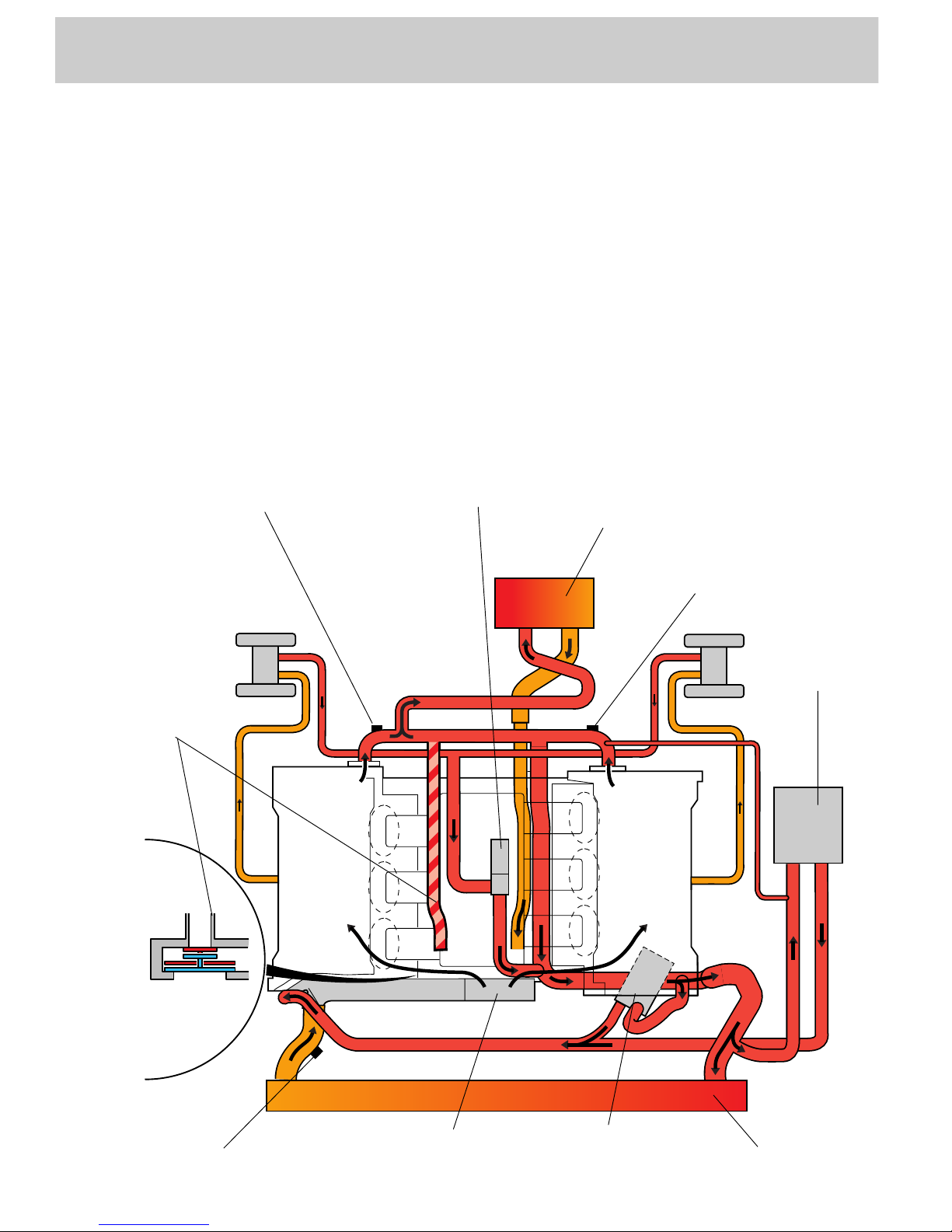
Cooling circuit
Both exhaust gas turbochargers are watercooled and integrated in the cooling circuit.
When the coolant thermostat is closed, the
coolant flows back to the coolant pump along
the short-circuit line as well as the heat
exchanger.
When the coolant thermostat is open, the
coolant flows back to the coolant thermostat
through the radiator (primary flow) or through
the oil cooler and expansion tank (secondary
flow).
Located in the cooling circuit is a electrical
coolant pump.
This pump is required as a means of
protection against overheating of the coolant
under high thermal load, e.g. when the hot
engine is turned off.
Short-circuit
line
Continued coolant function pump
Heat exchanger
Coolant
Expansion
tank
Radiator fan thermoswitch F18/F54
Oil cooler
Radiator
Thermoswitch for F95
Coolant temperature
senders G2 and G62
Coolant pump
10
SSP 198/10
Engine
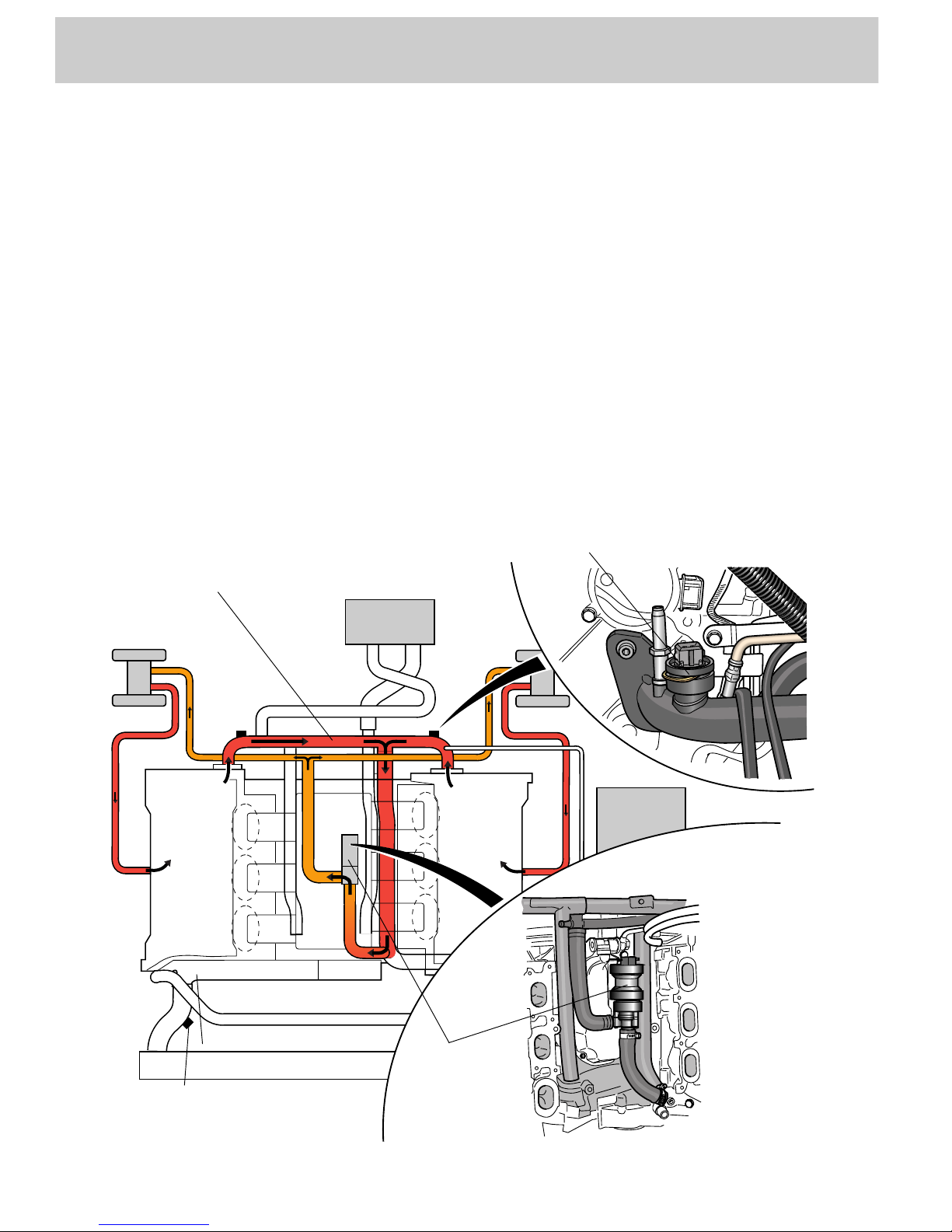
Electrical coolant circulation pump V51
Electrical coolant circulation pump V51 is
located in the engine’s V angle.
If the coolant temperature is too high,
thermoswitch for coolant circulation run-on
F95 activates the additional coolant function.
The high temperatures which occur at the
exhaust gas turbocharger produce vapour
bubbles which prevent coolant being drawn in
by pump V51.
When pump V51 starts up, the coolant flows
through the exhaust gas turbocharger and the
cylinder heads. The direction of flow in the
turbocharger cooling circuit is reversed by
this.
Due to this reversal of the direction of coolant
flow, coolant is drawn in via the cylinder heads
(large cross-sections), which means that any
vapour bubbles which develop are expelled
from the exhaust gas turbocharger lines.
The electrical coolant circulation pump again
draws in coolant along the rear coolant pipe,
thereby recirculating the coolant.
Rear coolant pipe
Electrical
coolant
circulation pump
V51
Thermoswitch for additional coolant
function F95
Radiator fan thermoswitch
F18/F54

11
Fan control
The control unit for radiator fan V293 regulates
the output of the radiator fan and controls the
continued coolant circulation. The induced-air
fan V7 and the forced-air fan V177 are
activated simultaneously.
Forced-air fan V177 is located upstream of the
condenser, water cooler and visco fan. It
assists the visco fan.
The electronic power control
The various fan settings are executed by an
electronic power control.
The fan motors are operated periodically, the
length of the operating cycle depending on the
fan setting selected. Fan output level is
controlled via pulse-width-modulated outputs.
Should a fan fail, the radiator fan control unit
increases the speed of the fan motor still
available.
Advantages of the power control:
•
The series resistors previously used for
power control are no longer required.
•
Lower power consumption in lower fan
settings.
•
Safety functions.
The power supply is protected by a
fuse on the 8-socket relay plate. For
the correct fuse rating, please refer
to wiring diagram.
Vehicles equipped with an air
conditioner require a higher fuse
rating than vehicles without an air
conditioner.
SSP 198/50
8-socket relay plate
SSP 198/55
Control unit for radiator fan
attached to front right
vehicle side member
Fuse, terminal 30
Fuse, terminal 61

12
Electric circuit of fan control:
Engine
for vehicles with air-conditioning system:
Integrated in the pressure switch for air
conditioner F129 is the high-pressure switch
for activating a higher fan setting.
The pressure switch is mounted below the
right-hand headlight behind the bumper.
Components:
F18/F54 Radiator fan thermoswitch
F95 Thermoswitch for continued coolant
function
F129 Pressure switch for air conditioner
(only for vehicles with air conditioner)
V293 Control unit for radiator fan
V7 Radiator fan (induced-air fan)
V51 Continued coolant circulation pump
V177 Fan 2 for radiator (forced-air fan)
(only for vehicles with air conditioner)
1 Terminal 30, positive supply via fuse
on 8-socket relay plate
2 Terminal 61, D+ (alternator) via fuse on
8-way relay
3 Fan activation (only for vehicles with
air conditioner)
M
_
V293
F18
F54
F129
V177
V7
V51
M
_
M
_
SSP 198/17
*
*
F95
*
P
P
1 23
only for vehicles with air conditioner
Air-conditioning pressure switch F129

13
Function of fan circuit
(for vehicles with air-conditioning
system)
4 fan settings are possible:
is activated by coolant pump thermoswitch
F95.
The fan motors and continued coolant
circulation pump V51 are activated.
The fan motors run at min. output (40%).
is requested by radiator fan thermoswitch F18
or by the air-conditioning control panel.
The fan motors run at 50% output.
is activated by air-conditioning system
pressure switch F129.
The fan motors run at 85 % output.
is activated by radiator fan thermoswitch F54.
The fan motors run at full output.
Fan speeds 1, 2 and 3 are only
activated if the “engine running“
signal is picked up at terminal 61.
The electrical coolant function.....
The continued coolant function is
only activated if the “engine not
running“ signal is picked up at
terminal 61. The continued coolant
function period is limited to 10
minutes.
Fan speed 1......
Fan speed 2......
Fan speed 3......
14 15
SSP 198/49
Engine
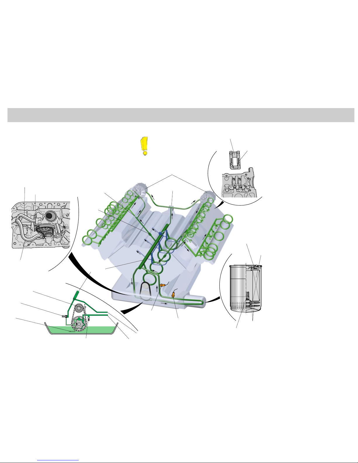
Engine lubrication
The oil circuit of the 2.7-litre V6 biturbo engine largely corresponds to that
of the 3rd V6 engine generation.
In addition, the two exhaust gas turbochargers are supplied with
pressurised oil from the main oil gallery via a distributor piece. The oil is
returned directly to the oil sump.
The oil cooler was adapted to withstand the higher thermal stresses in
comparison with a naturally aspirated engine.
A new feature of the biturbo is
the “integrated oil supply“ (see
next page).
to oil filter/oil cooler
Spring-loaded slipper
(chain tensioner)
Main oil gallery
Oil retention valves
Bypass valve
Filter element
Bearing cap
Oil groove
Oil temperature
sender
Oil pressure switch
Restrictor
Oil retention
valve
distributor piece
The oil circuit
A duocentric oil pump draws in the oil
through a coarse filter. Located in the
pressure chamber of the pump is a
pressure relief valve which protects
downstream components against
pressure peaks during cold starts.
The oil is fed to the oil filter via the oil
cooler. After passing an oil retention
valve, the oil flows through the filter
element. A bypass filter is connected in
parallel with the filter element.
The oil subsequently reaches the main
oil gallery. A branch line is routed to the
oil pressure control valve (clean oil
side).
The following components are supplied
with oil from the main oil gallery:
- the four crankshaft bearings
- the two exhaust gas turbochargers
via an oil distributor line
- the three pairs of piston spray jets via
a spray jet valve
- the cylinder head of cylinder bank 1
via an oil retention valve
The cylinder head of cylinder bank 2 is
supplied through a separate bore from
crankshaft bearing 2 via an oil retention
valve also.
First of all, the camshaft adjustment
valve is supplied with oil from the inlet
drilling in the cylinder head. After the oil
has passed by a restrictor, it is
channeled via the cylinder head main
gallery to the hydraulic valve tappets
and the camshaft bearings.
Exhaust gas turbocharger
Bypass filter
Oil pressure relief valve
from oil filter/oil cooler
Oil pressure
control valve
Induction filter
Oil pressure relief valve
from oil filter/oil cooler
to oil filter/oil cooler
16
Engine
The component parts of the oil circuit
is integrated in the primary flow. By increasing
the capacity and optimising the flow
resistance, the entire oil flow can be routed
through the oil cooler. Unlike the V6 naturally
aspirated engine, a bypass is not required.
The oil cooler ......
contains an oil retention valve, the filter
element, a bypass filter and the filter bypass
valve. The latter has the task of maintaining
engine lubrication via the bypass filter if the
filter element becomes clogged up or if the oil
has a high viscosity.
The oil filter ......
opens up the oil flow to the piston spray jets if
the oil pressure is greater than 1.8 bar.
Reason: at low oil viscosity and low engine
speeds, the oil pressure would otherwise drop
below the minimum permissible level. That
aside, piston cooling is not necessary at low
engine speeds.
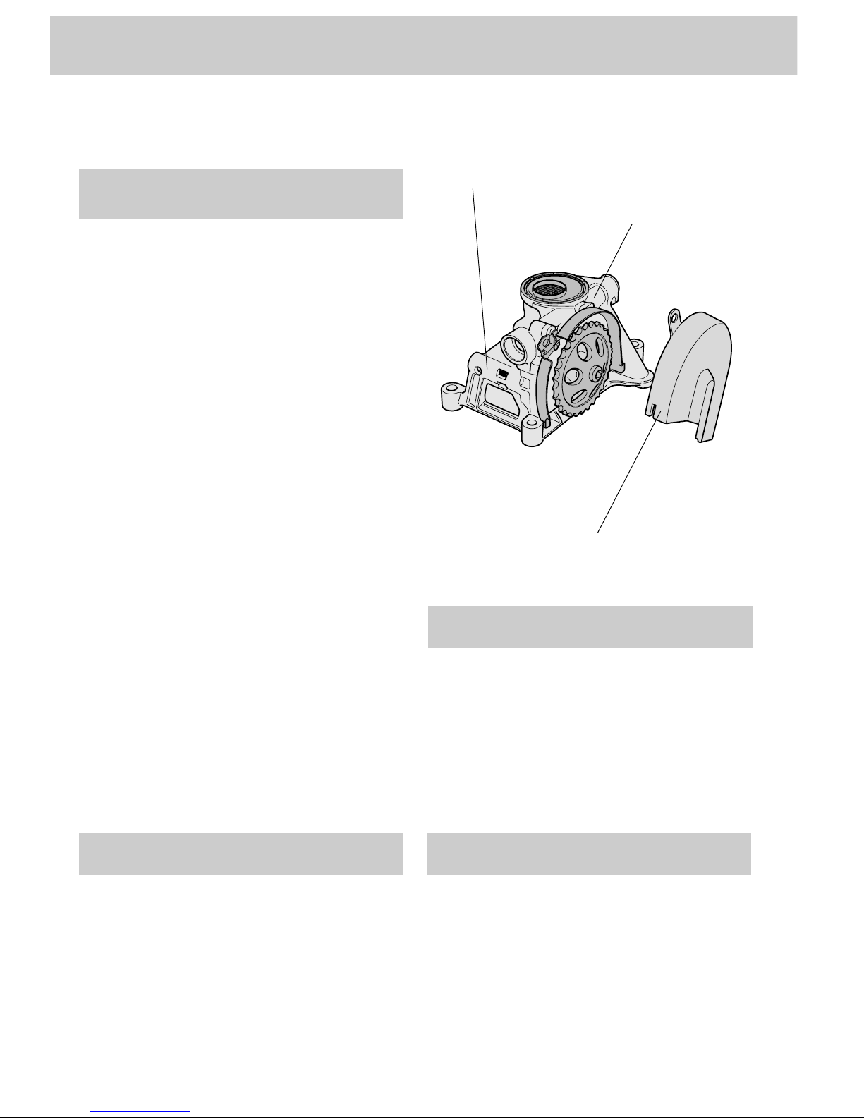
The spray jets valve ......
SSP 198/57
Oil pressure control valve
Oil pressure limiting valve
Chain guard
is an internal gear pump. It is attached to the
crankcase as a separate component.
The oil pump is designed in such a way that it
projects deep down into the oil sump and is
immersed completely in the engine oil when
the oil level is correct. This prevents the oil
pump running dry.
The oil pump, in combination with the
extremely short intake path, enables oil
pressure to build up more quickly and safely,
particularly during cold starts.
The oil pump is driven by the crankshaft by
means of a single chain.
A spring-loaded flat plate produces the
necessary tension.
A new feature of the oil pump is the chain
guard made from sheet steel. It encapsulates
both the chain wheel and the chain over a large
area.
This reliably prevents oil frothing and the
problems associated with this.
The oil pump ......
17
is a pressure relief valve. It is located inside the
oil pump housing and opens when the oil
pressure rises too high (cold start). If an
excessively high oil pressure builds up,
various component parts of the oil circuit (e.g.
oil filter, oil cooler) may be damaged. Also,
there is the possibility of the inlet and exhaust
valves opening or no longer closing, due to
“bulking“ of the hydraulic tappets. The knockon effect of this is that the engine can no
longer be started or cuts out.
The oil pressure limiting valve ......
regulates the engine oil pressure. It is
integrated in the oil pump housing. The oil
quantity “regulated“ by the oil pressure
control valve is fed to the suction side of the
oil pump.
This helps to optimise efficiency.
The oil pressure control valve ......
prevent the oil running out of the oil filter and
the cylinder heads and back into the oil sump
while the engine is stationary.
The oil retention valves ......
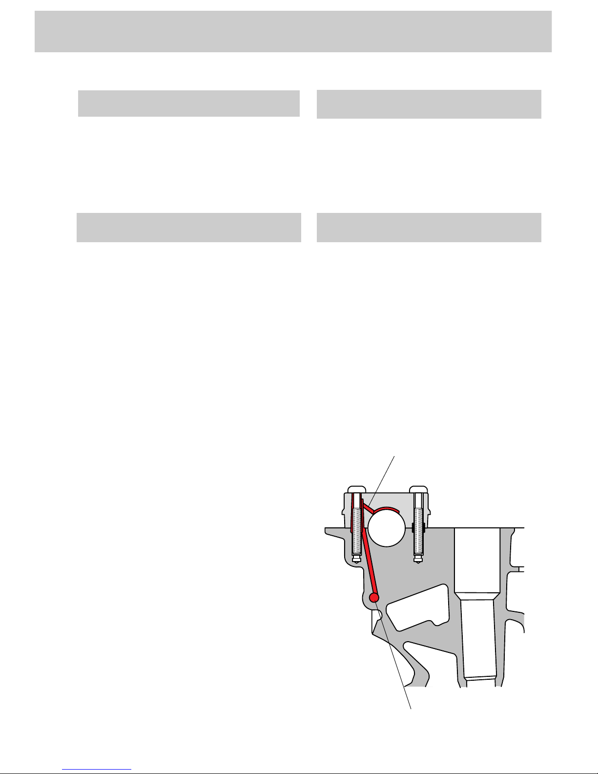
The “integrated oil supply“ ...
will also be adopted for all V6 5V naturally
aspirated engines.
Each camshaft bearing is supplied via a
drilling stemming from the cylinder head main
gallery.
The oil is fed along a bolt shaft in the bearing
cap to a transverse drilling.
A lubrication groove distributes the oil
throughout the camshaft bearing. It is no
longer necessary to run a pipe to the
individual bearing caps.
Advantages:
•
Fewer components
•
Quick and even oil supply
•
No additional installation work necessary
•
Lower cost
SSP 198/58
Cylinder head main gallery
Transverse drilling
prevent “flooding“ of the cylinder heads. At
high engine speeds, an excessively large
amount of oil enters the cylinder heads and
has to be returned to the oil sump via the oil
return drillings. The restrictors reduce the oil
flow and thereby ensure that return flow takes
place.
The restrictors ......
18
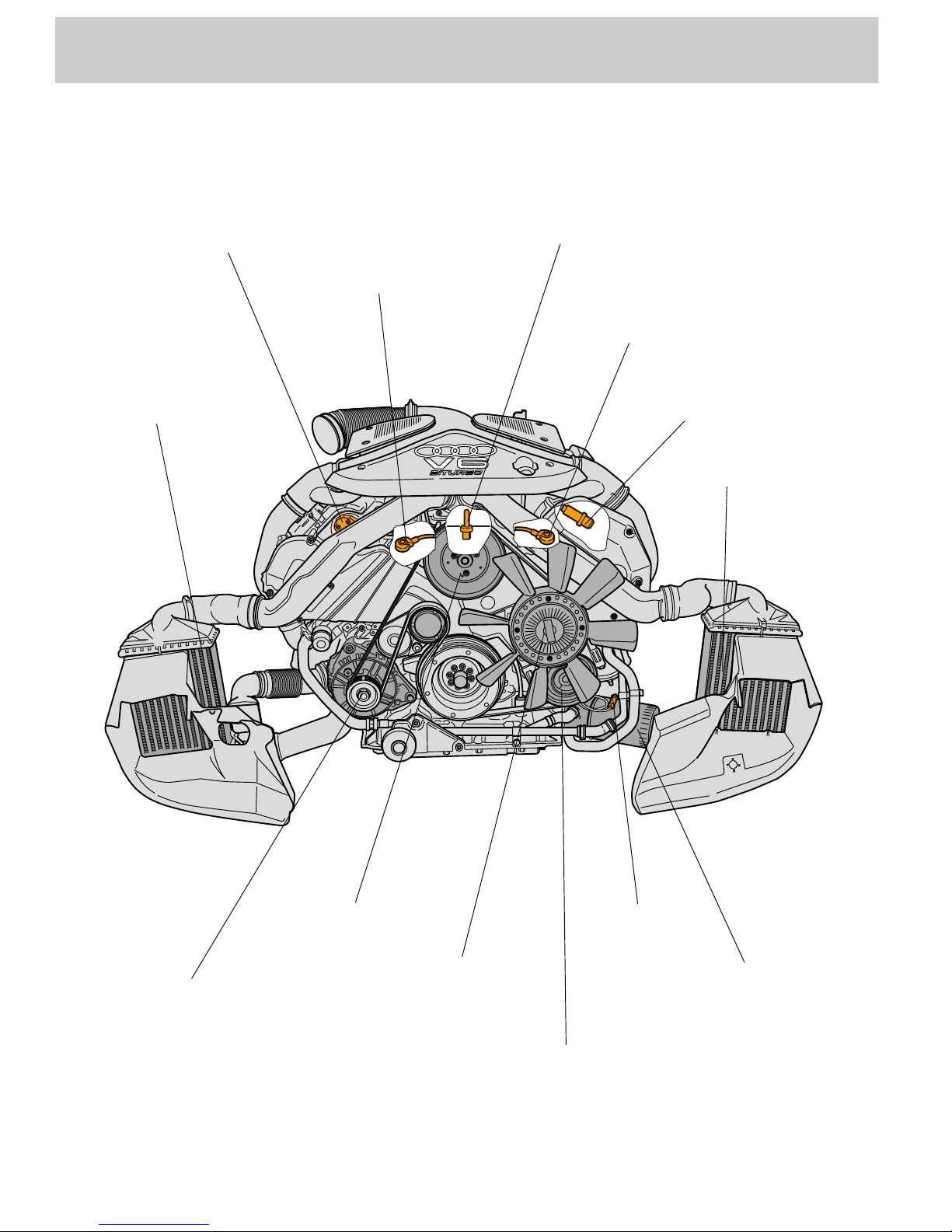
Front view of engine
SSP 198/51
Engine
Camshaft adjustment
valve N208
Knock sensor G66
Intake-air temperature
sender G42
Knock sensor G61
Hall sender G163
Charge air cooler
Charge air cooler
Oil filter
Oil pressure
switch
Air-cond. compressor
Visco fan
Alternator
Power assisted steering
pump drive
19
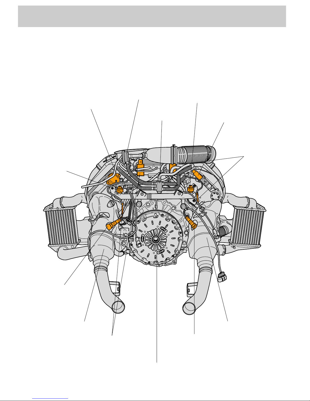
Rear view of engine
SSP 198/52
Hall sender G40
Thermoswitch for
continued cooling
function F95
Pressure limiting
valve
Distributor piece
Coolant temperature sender F18/F54
Camshaft adjustment
valve N205
Exhaust gas
temperature sender
G235 (with evaluation
electronics)
Lambda probe
G108
Exhaust gas temperature
sender G236 (with
evaluation electronics)
Lambda probe G39
SAC clutch pressure plate
Prim. catal. converter Prim. catal. converter
20
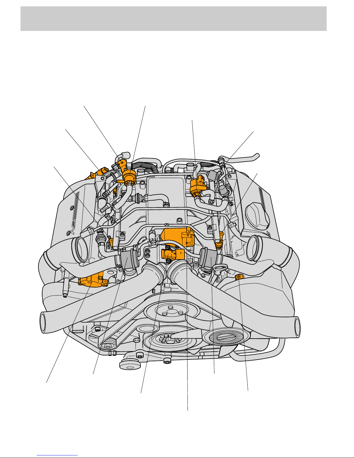
Engine
Top view of engine
SSP 198/54
Divert air valve for
turbocharger N249
Injector
Fuel pressure regulator
Solenoid valve for
activated charcoal
Solenoid valve for charge
pressure control N75
Camshaft
adjustment valve
N205
Injector
Hall sender G163
Divert air valve
Charge pressure
sender G31
Throttle valve
control part
Camshaft adjustment
valve N208
Divert air valve
21
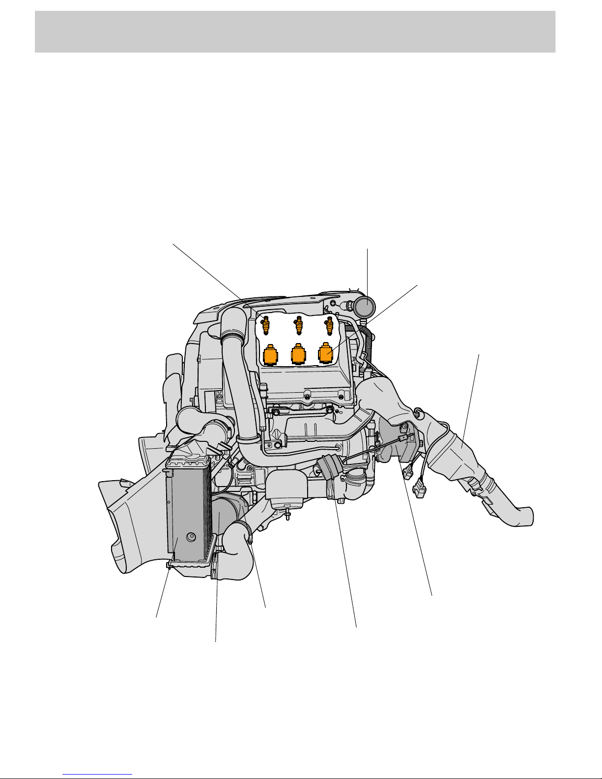
View of engine from left
SSP 198/53
Injector
Individual ignition coil
Pressure control valve
Prim. catal. converter
Exh. gas turbocharger
Pressure unit for
wastegate flap
Oil cooler
Oil filter
Charge air cooler
22
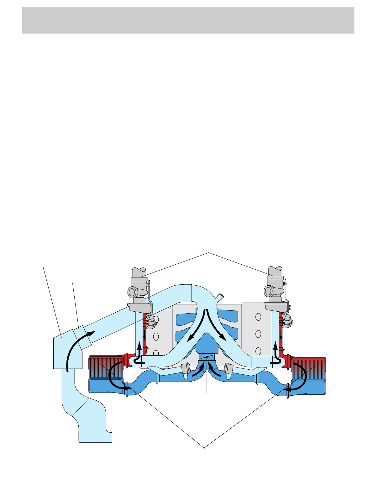
SSP 198/04
Engine
Air ducting
Fresh air is induced by the combined air filter
and air mass meter and distributed to the two
exhaust gas turbochargers by the air
distributor.
The air distributor is made of plastic.
Advantage:
•
Lower weight
•
The intake air is heated to a lesser degree
by the engine
The air, which is compressed and thus heated
by the exhaust gas turbocharger, is fed to the
charge air coolers.
Cooling air intakes in the bumper and air vents
in the wheel housing liners ensure that a
sufficient amount of air flows through the
charge air coolers.
Advantage of charge air cooling:
•
Cooled air has a higher density, and this
means improved volumetric efficiency.
•
The lower temperature reduces knock
tendency also.
The compressed air streams then converge
upstream of the throttle valve control part and
distributed to the individual cylinders in the
intake manifold.
Exhaust gas turbocharger
Throttle valve control part
Charge air cooler
Air distributor
Air mass meter
Air filter

23
SSP 198/32
Charging
Two water-cooled exhaust gas turbochargers
with wastegate are used for charging.
The charge pressure of both exhaust gas
turbochargers is controlled via the common
charge pressure control valve N75.
Advantages of the biturbo technology:
•
The exhaust gas turbocharger is smaller,
which means better response due its
reduced mass.
•
Higher charge pressure at low engine
speeds.
•
The exhaust gas turbochargers are located
outside the V-angle due to the high
temperatures they reach. This advantage of
this arrangement is that the intake air is not
heated up additionally and the subassemblies are not subjected to so much
thermal stress.
•
Since the turbochargers are flanged
directly onto the exhaust manifold, the
exhaust gases travel less distance and
there is less temperature loss.
•
As a result, the catalytic converters are able
to heat up more quickly and the efficiency
of the exhaust gas turbocharger is
improved by the favourable air-flow.
Intake side of exhaust
gas turbocharger
Charge press. side
of exh. gas turbocharger
Exhaust manifold
to exhaust system
Pressure unit for actuating
wastegate flap
Control pressure from
solenoid valve for
charge pressure
control
The turbochargers must be replaced
in pairs
To maintain a synchronous air-flow
through the two chargers, it is
important to observe this instruction
to account for manufacturing
tolerances.
Service personnel are not permitted
to adjust the linkage to the wastegate
flap.
Turbine housing
Compressor housing
 Loading...