

Page 1

1990
Audi 100
Audi 100 quattro
Owner’s
Manual
Page 2

Page 3

Your new Audi represents a consummate blend of sophisticated automotive technology and old world German
craftmanship.
It has been manufactured at the finest production facilities in the world, where the past and the future have come
together. Where g e ne ra tions of dedicated Audi cr a f ts men exercis e a linea ge of Audi thought, te chnique a nd pr ide .
As a descendant of the finest motorcars i n Germany, Audi began as an image in the minds of these craftsmen and
was the nurtured in their hands. This proud heritage originated with the prominent coach builders of the Auto UnionHorch, Audi, Wander e r & D K W .
Their vision and thei r practice continues in the creation of the most actively safe and reliable motorcars we can
manufac tur e.
We do this to mak e you the most as s ure d driv e r you can be.
Page 4

Your new Audi
may have all or some of the equipment
described in this manual. Therefore, you
may find explanations of equipment not
installed in your vehicle.
Check with your authorized Audi dealer
on available options or accessories.
Your Owner's Manual
applies to all Audi 100 and Audi 100
quattro models currently sold in the USA
and Canada, It contains important
operating safety information. Keep this
booklet in your glove box at all times for
ready reference.
Read it before you drive your new
vehicle. Pay particular attention to the
"Break-in period hints" and to all points
listed under "Vehicle operation".
Acquaint yourself with your vehicle's
features and know how to operate it
more safely. The more you know about
your Audi, the more you will enjoy driving
it. For your own protection and longer
service life of your vehicle, always heed
our instructions and warnings. Ignoring
them could result in extensive damage or
serious personal injury.
Note
WARNINGS concern safety and are
color identified throughout this
manual.
Please note that the items of equipment
marked with an asterisk* may be
standard on certain models but are only
available as options on other models.
In addition to this Owner's Manual, your
Audi 100/Audi 100 quattro comes with
§ the Radio Operating Instructions,
§ the Warranty Booklet and
§ the Maintenance Booklet.
Your Warranty booklet
which is a separate booklet, contains
detailed information about the warranties
covering your Audi.
Your Maintenance booklet
which is a separate brochure, explains
how you can keep your Audi in top
driving condition by having it serviced
regularly. Always have the Maintenance
booklet with you when you take your
vehicle to an Audi dealer for service.
Your Service Adviser will record each
scheduled service.
In Canada,
these manuals are also available in
French. To obtain a copy, contact your
dealer or write to:
Au Canada on peut se procurer un exempliaire de ce Manuel en francais aupres
du concessionnaire ou de:
Volkswagen Canada, Inc.
Customer Assistance
Assistance a la Clientele
1940 Eglinton Ave. East
Scarborough, Ontario
M1L2M2.
If you sell your Audi
the Owner's Manual, the Warranty booklet and the Maintenance booklet should
be left in the vehicle to make the Warranty terms as well as all operating, safety
and maintenance information available to
the next owner.
If you change your address or if you
bought this Audi used
be sure to send in a "Notice of Address
Change" / "Notice of Used Car Purchase" post card, This card can be found in
the Warranty booklet or obtained from
your Audi dealer.
It is in your own interest that we can
contact you should the need arise.
2
Page 5

INSTRUMENT PANEL
Illustration instruments
and controls..........................................4
Warning and indicator light
symbols ................................................ 6
CONTROLS AND EQUIPMENT
Keys, central locking system.............7,8
Anti-theft alarm system ......................11
Power windows, mirrors...............12, 13
Safety belts,
head restraints..............................15, 22
Seats, ski sack .............................23, 28
Luggage compartment,
Pedals........................................... 30,33
Brakes, transmission............... 34,38,39
Steering lock/ignition/
starter switch......................................42
Starting procedures............................43
Instrument cluster...............................44
Warning/indicators lights....................47
Auto-check system............................. 52
Trip computer.....................................56
Switches.............................................59
Light switch, turn signals,
cruise control................................62, 63
Windshield wipers,
emergency flasher........................64, 65
Heating, electronic climate
control system..............................66, 70
Sliding / prop-up roof..........................73
Telephone...........................................76
Roof rack............................................80
VEHICLE OPERATION
Break-in period – and afterwards.......81
Operate your vehicle safely................82
Operate your vehicle economically
and minimize pollution........................84
Trailer towing......................................85
Driving your Audi 100quattro..............87
VEHICLE CARE
Fuel tank, fuel supply.....................90,91
Vehicle care (exterior/interior)............94
Maintenance, inspection intervals......99
Engine hood,
engine compartment..................101,102
Lubricants, engine oil.................104,105
Engine oil filter..................................108
Transmission oil................................109
Power steering and brake booster...111
Brake fluid.........................................112
Cooling system.................................113
Battery ..............................................116
Windshield washers/wipers..............119
Tires/wheels......................................121
Difficult operating conditions............127
Winter driving....................................128
Accessories......................................129
DO-IT-YOURSELF SERVICE
Jack and tools...................................130
Compact spare wheel.......................132
Changing a wheel.............................133
Fuses, bulbs.............................136, 138
Adjusting headlights .........................143
Replacing the radio...........................144
Emergency starting...........................145
Emergency towing............................148
Lifting vehicle....................................150
TECHNICAL DESCRIPTION
Engine transmission.........................151
Suspension, brakes, steering, body.152
Emission control system...................153
Digital electronic ignition...................155
All-Wheel drive..................................156
Safety system "ten", Air bag......159,160
TECHNICAL DATA
Engine, spark plugs. V-belts......162,163
Capacities, dimensions.....................164
Weights.............................................165
Vehicle identification.........................166
CONSUMER INFORMATION
Service manuals...............................167
GAS STATION INFORMATION
Location of servicing points..............170
ALPHABETICAL INDEX
Alphabetical index.............................172
3
Page 6
INSTRUMENT PANEL AND CONTROLS
INSTRUMENT PANEL AND CONTROLS
4
4
Page 7

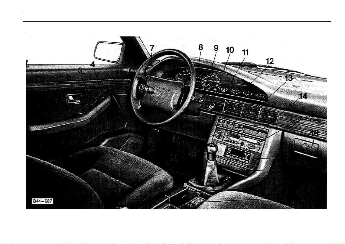
INSTRUMENT PANEL AND CONTROLS
page
1 – Door Handle..............................................................8
2 – Seat Position memory switch control......................25
3 – Power window switches ..........................................12
4 – Adjuster control for outside mirrors.........................13
5 – Turn signal/headlight dimmer switch lever..............62
Cruise control ..........................................................63
6 – Light switch..............................................................62
7 – Side window defroster nozzles................................66
8 – Emergency flasher switch lever..............................65
9 – Windshield wiper/washer lever................................64
Trip computer function control switch.....................56
10 – Steering lock/ignition/starter switch.........................42
11 – Instrument cluster and warning/indicator lights.......44
12 – Thumbwheel for air vents........................................66
13 – Air vents...................................................................66
page
14 – Switches for
– Electrically heated driver’s seat.............................. 59
– Rear window defogger............................................ 59
– Rear fog light........................................................... 59
– Anti-lock brake system (ABS)................................. 60
– Electrically heated front passenger's seat..............59
– Storage tray ............................................................79
15 – Radio1)
16 – Glove compartment (lockable) ...............................78
17 – Climate controls...................................................... 66
18 – Ashtray.................................................................... 78
19 – Parking brake lever................................................. 37
20 – Differential lock (Audi 100 quattro)......................... 61
21 – Horn ...................................................................... 160
Air bag2)
22 – Release lever for engine hood .............................101
23 – Cigarette lighter/electrical socket............................ 77
24 – Gearshift lever.........................................................38
Note
Some features mentioned are standard equipment on some
models only or are options on others.
1)
A separate brochure is provided for your f actory-installed radio. If
you replace your radio, please be sure to read the notes in the
chapter "Do-it-yourself Service", page 144.
2)
USA models only
5
Page 8
INSTRUMENT PANEL AND CONTROLS
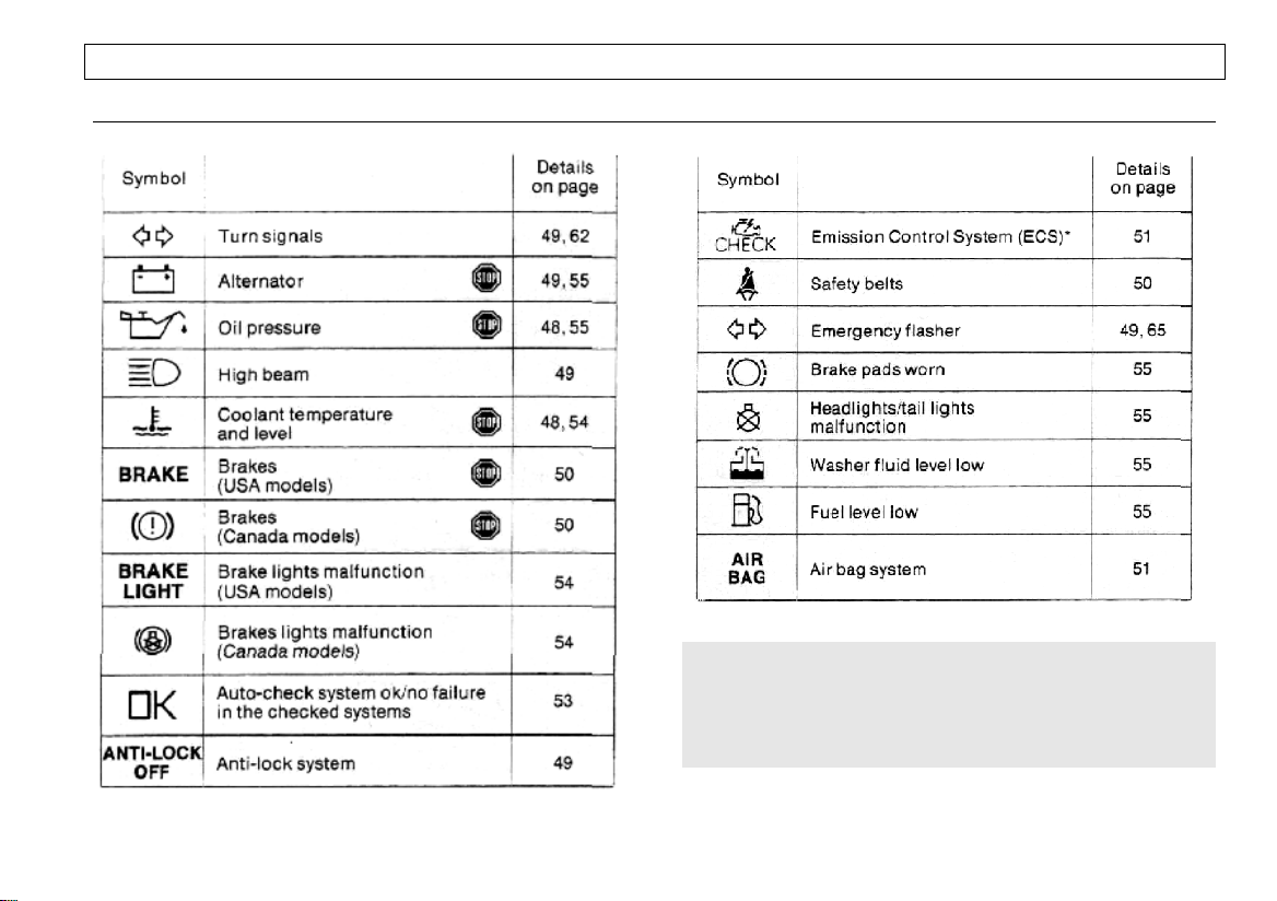
WARNING AND INDICATOR LIGHT SYMBOLS
*where applicable
WARNING
if one of the lights marked with "STOP" comes on suddenly
while driving, move a safe distance off the road. Turn off the
engine, turn the emergency flasher on and use other warning
devices to alert other motorists. Go to listed page in your
owner's manual for explanations.
6
Page 9
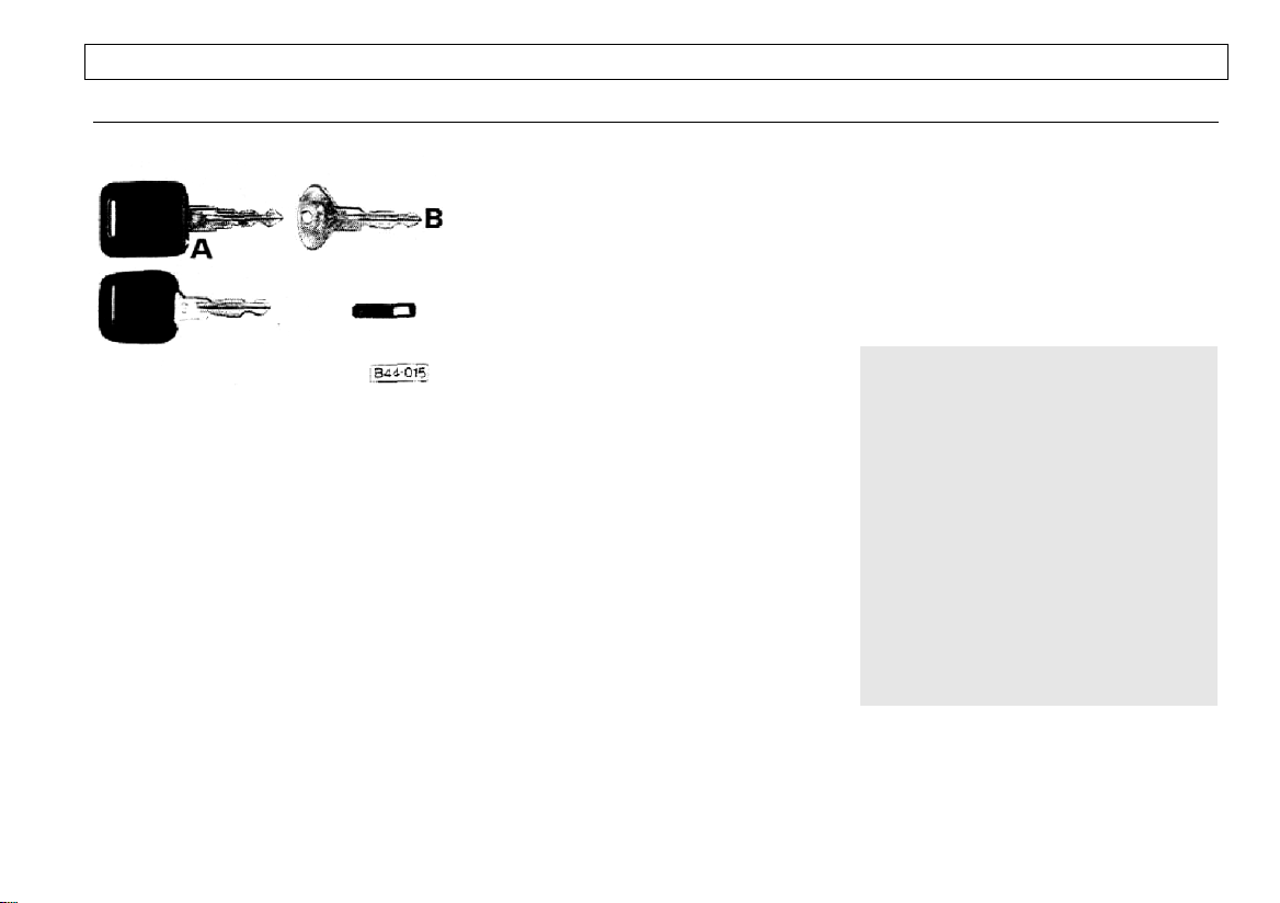
KEYS
CONTROLS AND EQUIPMENT
Your Audi comes with three keys:
§ two keys A (one with a light)
§ one key B.
All keys can be inserted into locks either
way,
Key A is the master key and fits all locks
on the vehicle.
To switch on key with light:
§ Press round button in the center of
the key handle and hold.
To replace battery or bulb:
§ Insert a coin in the slit at the side of
the key head and pry out cover.
§ Replace battery or bulb.
Spare batteries or bulbs are available at
your Audi dealer.
Key B is the secondary key and is only
for the doors, the steering/ignition lock,
and the lockable tank cap. The luggage
compartment and glove compartment
cannot be opened with this key.
Tag C gives the key number.
For your protection against theft:
§ Record the key number and keep it
in a safe place, such as your wallet. Do
not keep it in the vehicle.
§ If you should lose a key, provide
your Audi dealer with the key number to
obtain a duplicate key.
in addition to the plastic tag, there may
also be a metal tag showing part of the
vehicle identification number. This tag is
no longer required after the vehicle has
been delivered.
§ Do not leave your vehicle
unattended with the key in the ignition
lock. Take the key and lock the doors.
A chime will sound when you open the
driver's door with the key left in the
ignition lock. This is your reminder to
remove the key and lock the doors.
If the chime continues to sound after
pulling out the ignition key and opening
the door, you have forgotten to turn off
the headlight switch and/or the radio.
WARNING
§ Do not leave children unattended
in the vehicle especially with access
to vehicle keys. Unsupervised use of
the keys can result in starting of the
engine and use of vehicle systems
such as power windows, power
sunroof, etc. Unsupervised use of
these systems can result in serious
personal injury.
§ Do not remove key from steering
lock while you are driving or as the
vehicle is rolling to a stop. The
steering column wilt lock when you
remove the key, and you will not be
able to steer the vehicle.
7
Page 10
CONTROLS AND EQUIPMENT
EM CENTRAL LOCKING SYST
The central locking system locks or unlocks doors and the rear lid simultaneously. It is actuated from the driver's or
front passenger's door.
When the ignition key is fully inserted in
the ignition lock, the central locking
function from the front passenger's door
is partially deactivated: raising the locking
knob in the front passenger's door will
unlock all doors, however, depressing
the locking knob will only lock this
particular door.
When the central locking system is actuated, all locking knobs on window sills
should move simultaneously. If one knob
does not move when locking doors, open
that particular door and close it properly.
If the driver's door is open, it cannot be
locked from the front passenger's door.
When you unlock the driver's or front
passenger's door with the key from
the outside or raise the locking knob
in either front door from the inside,
wait until all locking knobs are raised
before you open one of the doors. In
the winter, it can take a few seconds
until all knobs are raised.
The rear lid can be locked and unlocked
individually with the key; manual lock
operation will override the power lock
system.
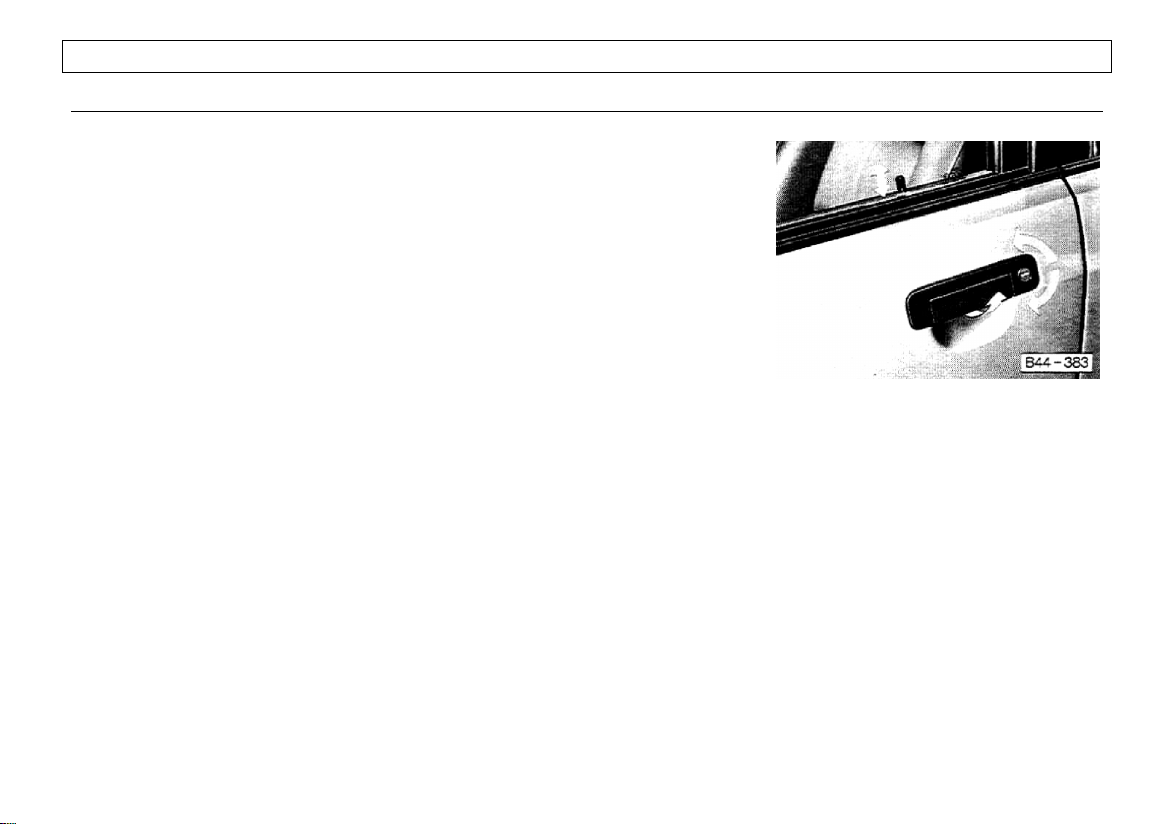
To lock, unlock and open doors from
the outside
§ Lock and unlock, turn master or sec-
ondary key in lock of driver's or front
passenger's door.
§ Open the doors by pulling up on the
handle (arrow).
§ All doors (except the driver's door)
can be locked by first depressing locking
knob and then closing the door.
§ The driver's door can only be locked
from the outside with the key. This precaution was taken to prevent locking the
driver's door while the key is still inside
the vehicle.
8
Page 11
To lock, unlock and open doors from
the inside
§ To lock or unlock depress or raise
the locking knob on the window sill of the
front doors. When the key is fully inserted
in the ignition lock, the doors can only be
locked simultaneously by actuating the
locking knob in the driver's door.
Depressing the knob will lock all doors
and prevent opening the doors from
inside and outside.
§ To open doors, raise locking knob in
driver's or front passenger's door and pull
the inside door handle.
The rear doors can be locked or
unlocked independently of the central
locking system with the locking knob in
each particular door.
WARNING
§ Locking doors from the inside
can help prevent inadvertent door
opening during an accident and
generally while the vehicle is in
motion. Locked doors can also
prevent unwanted entry from the
outside. Locked doors can, however,
also delay assistance to vehicle
occupants and rescue from the
outside in the event of an accident or
other emergency.
§ Do not leave children inside the
vehicle without supervision, if the locking
knobs in the driver's or front passenger's
door are depressed, all doors will be
locked automatically. In an emergency it
would be impossible to open the doors
from outside without a key.
CONTROLS AND EQUIPMENT
Child lock for rear doors
To prevent children riding in the back
seat from accidentally opening the rear
doors, a safety mechanism is provided.
§ To engage child lock, move small
lever at lower edge of lock inward.
§ Close door.
§ Child lock is securely engaged if rear
doors cannot be opened from the inside
with locking knob in either raised or
depressed position.
Rear doors can be opened from the
outside only when locking knob is raised.
Remember, when the child safety locks
are engaged, the rear doors can only be
opened from the outside
Deactivate child lock when no longer
required.
9
Page 12
CONTROLS AND EQUIPMENT
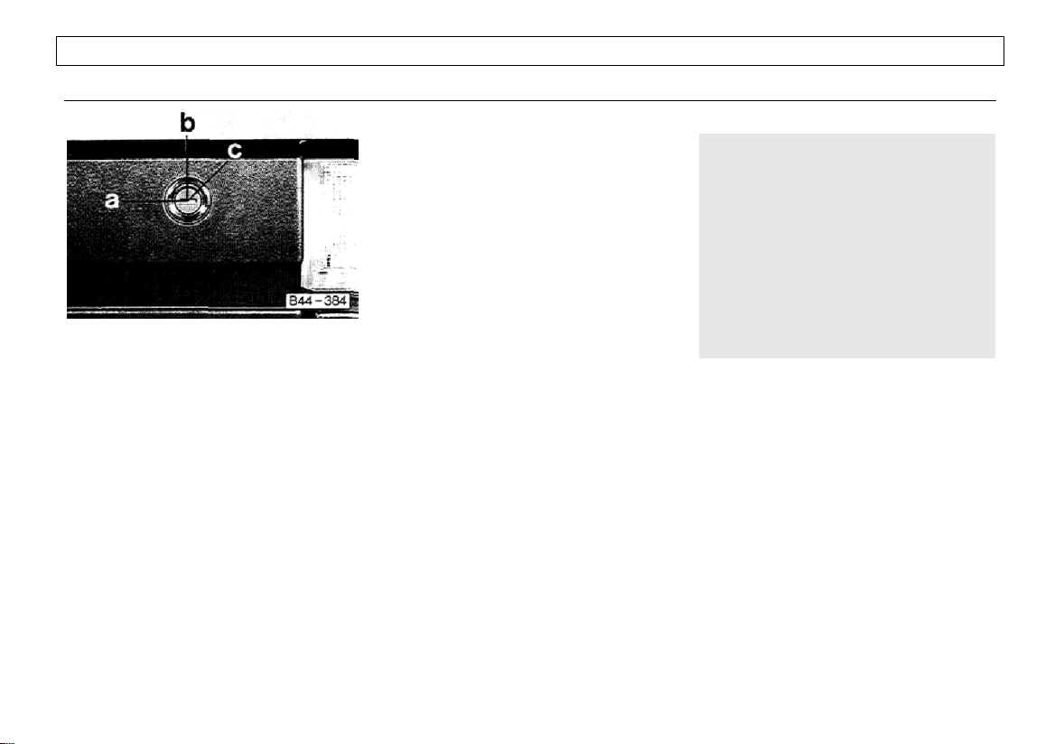
Rear Iid
§ With the key slot in horizontal
position (a), the lid can be locked and
unlocked by the central locking system.
§ With key slot in vertical position (b),
the rear lid remains locked when
actuating the central locking system. This
provision has been made to facilitate
permanent locking of the rear lid when
leaving your vehicle in a public garage or
workshop. Take master key with you and
leave secondary key with attendant.
If the rear lid is closed with lock slot in
vertical position, the luggage
compartment can only be opened with
the master key:
§ Insert key in lock slot.
§ Turn key all the way to the right (c)
and hold in this position.
§ Press lock cylinder in and raise lid,
§ Remove key.
The luggage compartment light will come
on when the rear lid is opened.
§ To close rear lid, swing lid down
firmly.
Keep the rear lid locked at all times to
prevent unauthorized access to the
vehicle.
WARNING
§ When closing the rear lid of the
Wagon/Avant always check whether
the catch has engaged properly by
trying to lift the lid. If this is not the
case, the lid may suddenly fly open
while driving even though it has been
locked.
§ To help prevent poisonous
exhaust gas from being drawn into the
vehicle, always keep the rear lid
closed while driving.
Do not transport objects larger than
those fitting safely into the luggage
area.
10
Page 13

HEATED DOOR LOCKS* ANTI-THEFT ALA RM SYSTEM 1)
CONTROLS AND EQUIPMENT
On vehicles with heated front door locks
the heating in the lock cylinder is
activated by briefly pulling the door
handle. The heating operates at ambient
temperatures below about 41° F or +5°C.
The element stays on for a
predetermined period which is controlled
automatically according to the ambient
temperature, but not longer than about
50 seconds. It is not possible to extend
this period by pulling the door handle
continuously.
Once the heating has switched itself off,
it can be reactivated by pulling the door
handle again.
. 1
)USA Models only
.
The anti-theft alarm system triggers an
acoustic alarm and switches on the
emergency flasher if it senses unauthorized interference with the vehicle.
When the vehicle is locked the alarm
system monitors and protects the
following parts of the vehicle:
§ engine compartment
§ luggage compartment
§ doors
§ radio
§ ignition.
*
The windows and sliding/prop-up roof
are not monitored.
The alarm system is switched on automatically when the driver's or front passenger's door is locked, and switches off
when either door is unlocked. The system becomes active about 30 seconds
after the vehicle is locked.
The horn sounds briefly when the vehicle
is locked to confirm that the alarm system
is operative and that all doors are
properly closed. If the horn does not
sound, check trie doors and close them
properly. The horn will not sound if a door
is closed when the system is already
switched on.
*
* where applicable
The rear lid can be opened separately
with the key even when the system is
active. This will not trigger the alarm.
When the rear lid is closed the luggage
compartment will again be included in the
alarm circuit.
The alarm will be triggered if one of the
doors, the engine hood or the rear lid are
opened without using the key, or if the
ignition is switched on or the radio
removed. When the alarm is triggered
the horn sounds and all four turn signals
flash simultaneously for about 4 minutes.
The engine cannot be started until the
system is switched off with the key at
either the driver's or front passenger's
door.
The alarm will be triggered a second time
if one of the protected parts of the vehicle
is interfered with again after the alarm
has stopped (for instance if the radio is
removed after one of the doors has been
forced open).
11
Page 14
CONTROLS AND EQUIPMENT
POWER WINDOWS
Normally, the power windows can be
opened and closed only with the ignition
on.
However, when the ignition is off the
windows can still be operated as long as
the driver's door is closed. When the
driver's door is opened, power window
operation will be deactivated.
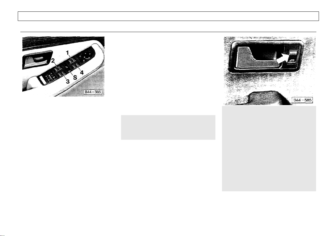
The control switches for alt windows are
installed in the armrest of the driver's
door (see above illustration).
An additional switch is installed in each
armrest for the convenience of front and
rear passengers (see right illustration).
§ Switches 1 and 4 operate the front
door windows.
§ Switches 2 and 3 operate the rear
windows.
§ Safety switch S serves to activate
the switches in the rear doors.
§ To open the left front door window
push the rear of switch 1 briefly. The
window will open fully and quickly for the
driver's convenience.
For intermediate open window positions,
the front of switch 1 must be depressed
briefly.
§ To close the left front door window,
the front of switch 1 must be depressed
continuously until the window is
completely closed.
WARNING
Do not put anything on or near the
windshield or any other window that
may interfere with the driver's v ision.
The rear windows can only be opened
and closed and the cigarette lighter only
works when the safety switch (S) in
driver's door is depressed. This feature
has been provided for the safety of small
children riding in the rear of the vehicle.
WARNING
Do not leave children unattended in
the vehicle especially with access to
vehicle keys. Unsupervised use of the
keys can result in starting of the
engine and use of vehicle systems
such as power windows, power
sunroof, etc. Unsupervised use of
these systems can result in serious
personal injury.
Remember also that the power
windows are inoperative only after the
ignition key has been removed and
the driver's door opened.
12
Page 15
MIRRORS
CONTROLS AND EQUIPMENT
Adjust the outside and inside mirrors
before driving and after adjusting your
seat to proper driving position. It is
important for safe driving that you have
good vision to the rear.
The outside mirrors are hinged and yield
when struck from either direction.
WARNING
§ The right hand mirror has a
curved (convex) surface. Always
remember that vehicles or other
objects seen in a convex mirror will
look smaller and appear farther away
than when seen in a flat mirror. Do not
use this mirror to estimate distance of
following cars when changing lanes.
§ The left hand mirror may have an
aspherical surface with different
angles. This mirror increases the area
of vision even more than a convex
mirror. Therefore, do not use this
mirror to estimate the distance of
following cars when changing lanes.
Whenever possible, use the inside
mirror to determine the actual
distance and size of vehicles or
objects seen in the convex mirror.
If the electrical adjustment of the mirror
should not respond, the mirrors can still
be adjusted by pushing lightly on the
edge of the mirror glass.
When the rear window defogger is
switched on, the outside mirrors are
electrically heated at the same time (see
page 59).
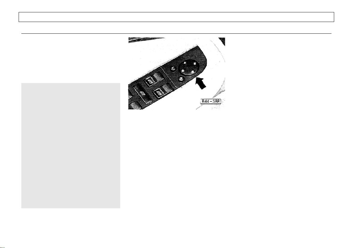
Outside mirrors
The outside mirror should be adjusted so
that the side of your own vehicle can just
be seen. This setting ensures the best
possible field of view, and in addition it
serves as an instant check on the mirror
setting.
With the ignition on, both outside mirrors
can be adjusted using the rocker switch
(arrow).
§ Push button (L) to adjust the mirror
on the driver's side, button (R) for the
mirror on the passenger's side.
§ To adjust the position of the mirror,
push the rocker switch in the direction
you wish to move the mirror surface.
13
Page 16
CONTROLS AND EQUIPMENT
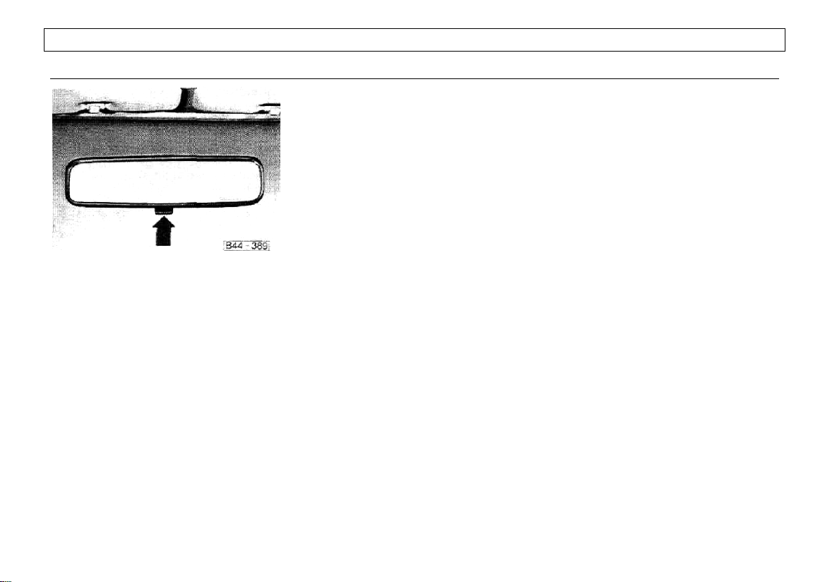
Inside day-night mirror
You can adjust the day-night mirror from
clear daylight visibility to non-glare
visibility at night by moving the lever at
the bottom of the mirror.
To ensure the best possible anti-glare
effect, the lever should be pointing
forwards when the basic mirror setting is
made.
Daylight driving – lever to front
Night driving – lever to rear
14
Page 17

SAFETY BELTS
WARNING
Safety belts have been shown to be
the single most effective means available for reducing the potential for
serious injury and death in automobile
accidents. Therefore for your own
protection as well as that of your
passengers always properly wear
safety belts when the vehicle is in motion. Also pregnant women, injured or
physically impaired persons should
use safety belts.
In order to provide the maximum level
of protection safety belts must be
property positioned on the body.
Improperly positioned safety belts can
cause serious personal injury in case
of an accident. Therefore read and
always observe all of the following
instructions and warnings pertaining
to the use of the safety belts installed
in your vehicle.
§ When fastening the tap/shoulder
belt, the shoulder belt should be
positioned midway over the shoulder never across the neck. See illustration
on page 19.
§ Always make certain that the
safety belt tongue is inserted into the
safety belt buckle associated with the
corresponding seat. Attaching the
15
safety belt to the buckle for another
seat could reduce safety belt
effectiveness and cause injury.
§ The combination lap/shoulder belt
on the front seats can be adjusted to
fit comfortably – see page 18.
§ Do not wear shoulder part of belt
under your arm or otherwise out of
position. This would increase the risk
of serious injury in case of an
accident.
§ Do not use comfort clips or devi-
ces which create slack in the shoulder
belt portion and can increase the risk
of injury in an accident. However such
clips may be required in the proper
use of some child restraint systems.
§ Never strap in more than one
person, including small children, with
each belt. It is especially dangerous to
place a safety belt over a child sitting
on your lap.
§ The lap belt must be worn low
and tight across the pelvis. Make sure
any slack is wound on the retractor,
§ Belts should not be worn twisted.
§ Do not wear belts over rigid or
breakable objects in or on your
clothing, such as eye glasses, pens,
keys, etc. as these may cause injury.
CONTROLS AND EQUIPMENT
§ Several layers of heavy clothing
may interfere with proper positioning
of belts and reduce the overall
effectiveness of the system.
§ Keep belt buckles free of any
obstruction that may prevent secure
locking.
§ Make sure the belts of the
unoccupied seats are in their stowed
positions.
§ Belts that have been subjected to
excessive stretch forces in an
accident must be replaced.
§ Belts must not rub against sharp
objects.
§ Do not allow safety belts to
become damaged by becoming
caught in door or seat hardware.
§ Inspect your belts periodically, If
belts show damage to webbing,
bindings, buckles or retractors, they
must be replaced.
§ If belts do not work properly, see
your Audi dealer.
§ Do not modify or disassemble the
safety belts in your vehicle.
Page 18

CONTROLS AND EQUIPMENT
WARNING continued
§ The belts must be Kept clean as
otherwise the retractors may not work
property (also see "Vehicle care",
page 97).
§ Never bleach or dy e safety belts.
§ Do not allow safety bells to retract
until they are completely dry
Child safety
WARNING
AH vehicle occupants and especially
children should be restrained when
ever riding In cars. Holding a child in
your arms is not a substitute for a
child restraint system. In an accident,
a child held in a person's arms can be
struck or crushed by any unrestrained
rider. An unrestrained child could also
be injured by striking the interior, or
by being ejected from the vehicle
during a sudden maneuver or impact
Do not allow children to stand or
kneel on the seat. A child restraint
system can help protect a child in a
car.
Accident statistics have shown that
children are generally safer in the rear
seat area than in the front seating
positions.
A suitable child restraint properly
installed and used at one of the rear
seating positions provides the highest
degree of protection for infants and
small children in most accident
situations.
Commercially available child seats are
required to comply with U.S. Federal
Motor Vehicle Safety Standard
(FMVSS) 213 (or in Canada, CMVSS
213). These standards include
installation requirements which utilize
a tap belt or the lap portion of a
combination lap-shoulder belt such as
that installed in your vehicle.
Should these safety belts be too
short, a special lap belt adapter is
available from your A udi dealer.
When purchasing a child restraint,
select one which properly fits your
child and your car.
Only use child restraint systems
which fully contact the flat portion of
the seat cushion. The child seat must
not tip or lean to either side. We do
not recommend the use of child seats
which rest on legs or tube-like frames
because they do not provide adequate
contact with the seat.
16
Page 19

CONTROLS AND EQUIPMENT
Improperly or Inadequately instated
child restraint systems can increase
the risk of injury to children in
accidents, therefore always carefully
read and follow all instructions on
installation and use that come with
the system.
Children must be positioned so that
the shoulder belt does not contact or
remain in front of the face, chin, neck
or throat. Failure to follow this
precaution can increase the risk or
severity of injury in the event of a
collision.
In summary:
Children who are less than 12 years
old should always sit in the rear.
For reasons of safety a child should
only occupy the front seat if all of the
rear seating positions are already
occupied by other children.
The children should wear, depending
on age and body size, either a child
restraint system or the existing safety
belts:
§ Babies and children up to about 6
or 7 years should be secured with a
child restraint system designed for
their size.
§ Children of average size of about
6 or 7 years of age may use available
safety belts. Always make sure that
the shoulder portion of a three point
belt is positioned midway over the
shoulder – it must never rest against
or across the neck. See illustration
page 19. The lap belt or the lap belt
portion of the three point belt must
always pass as low as possible
across the pelvis, never over the
abdomen.
If the safety belt will not properly fit
the child, we recommend the use of a
suitable booster seat in a rear seating
position in order to raise the child's
seating height so that the safety belt
will properly fit the child.
17
Page 20
CONTROLS AND EQUIPMENT
Belt warning system
A chime and a warning light are
interconnected with the driver's safety
belt.
Every time the ignition is turned on, the
safety belt warning light will come on for
about six seconds as a reminder to
buckle up. If the driver does not fasten
the safety belt, the chime will also come
on for the duration of this six second
period. With the driver's door closed, the
chime will go off as soon as the driver
has buckled up.
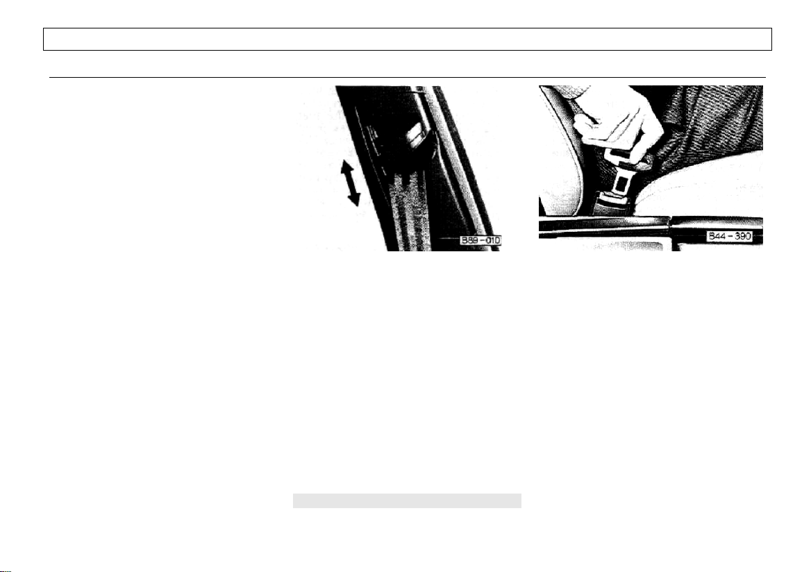
Adjusting shoulder seat belt
The front seat shoulder belt anchor on
the door pillar can be adjusted up or
down to accommodate the height of the
driver and the front passenger. The
second position from top is the standard
position.
§ To adjust push the handle up or
down to position the shoulder belt
midway over the shoulder – never
across the neck. See illustration on the
next page.
§ Pull on the shoulder belt to check
whether belt anchor is securely locked in
place.
Lap-shoulder belt
The combination lap-shoulder belt is
equipped with a locking retractor. The
system adjusts automatically to your size
and movements as long as the pull on
the belt is slow.
Hard braking or a collision locks the belt.
The belt will also lock when you drive up
or down a steep hill or in a sharp curve.
§ Before fastening the safety belt first
adjust your seat-see page 23.
§ To fasten, grasp belt tongue and pull
belt in continuous slow motion across
your chest and lap.
18
Always heed WARNINGS on page 15
Page 21
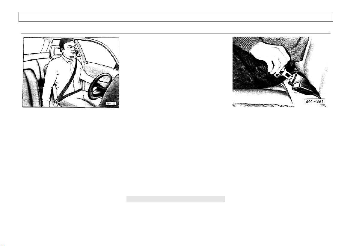
§ Insert belt tongue into buckle on
inboard side of seat. Push down until it is
securely locked with an audible click. Pull
belt to check.
§ Pull upwards on shoulder section to
make sure belt fits snugly across the
pelvis.
§ The shoulder belt must be posi-
tioned over the shoulder – it must never
rest against the neck. See illustration.
§ Belts should fit snugly across the
pelvis and chest. Make sure any slack
is wound up on the retractor.
§ Adjust height of belt anchorage, if
necessary. Do not wear shoulder part of
belt under your arm or otherwise out of
position. This would increase the
possibility of serious injury in case of an
accident.
§ To unfasten belt, push in release
button on buckle, Belt will spring out of
buckle.
§ To release a locked belt, lean back
to take the body pressure off the belt,
§ To store lap-shoulder belt, allow belt
to wind upon retractor as you guide belt
tongue to its stowed position.
Always heed WARNINGS on page 15
CONTROLS AND EQUIPMENT
Lap belt
The lap belt for the rear center seating
position is equipped with a retractor.
The automatic retractor will lock the lap
belt when your passenger has buckled
up, and the remaining slack has been
retracted. Make sure any slack is
wound on the retractor.
The belt can only be pulled out after it
is fully retracted.
§ To fasten lap belt grasp belt tongue
on outboard side of seat and slowly and
evenly pull across the pelvis. Insert belt
tongue into the respective buckle and
push down until it is securely locked with
an audible click. Pull belt to check.
19
Page 22

CONTROLS AND EQUIPMENT
WARNING
§ To reduce the risk of injury m an
accident, position the lap belt as low
as possible across the pelvis.
§ To unfasten belt, push in release
button in the buckle.
§ To fasten lap belt, grasp belt tongue
on outboard side of seat, pull across
pelvis and insert in inboard buckle.
Always heed WARNINGS on page 15
20
During pregnancy
Pregnant women should always wear
safety belts. The lap belt must be worn
snugly and as low as possible across the
pelvis. To avoid pressure on the
abdomen the belt must never pass over
the waist.
Injured persons and the physically
impaired
We recommend that injured persons and
the physically impaired wear safety belts
whenever possible. Although the
instructions provided above still apply,
your doctor can give you special
recommendations when necessary.
Safety systems
ten
The vehicle is equipped with the "ten"
safety system which gives the driver and
front passenger greater protection in an
accident, provided that they are
wearing safety belts.
The system automatically pretensions
the safety belt for the driver and the front
seat passenger in the event of a severe
frontal impact.
The system is described on page 159.
Air bag
The air bag system, in conjunction with
the "ten" safety system, gives the driver
additional protection in a severe frontal
impact, provided that he wears the
safety belt.
More details on page 160.
1
1
USA models only
Page 23
Child restraint anchorages
(USA models)
WARNING
Children under about six years of age
should not wear lap belts.
Depending upon the child restraint
system to be fitted, additional anchorage
points may be required for USA vehicles.
Audi 100 sedans can be fitted with three
anchorage points on the filler panel for
use with certain types of child restraints
requiring a tether strap.
Ask your Audi dealer for installation of
one or more anchor points and the
required hardware for the attachment of
the tether.
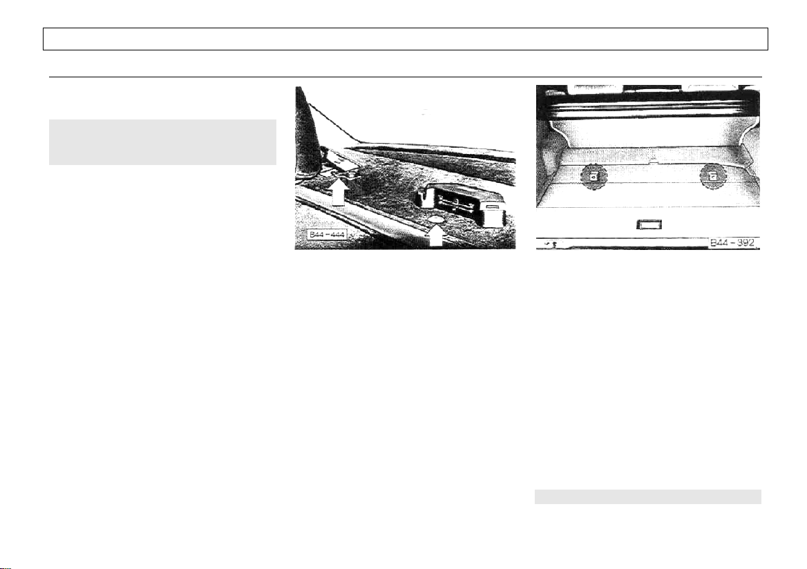
Child restraint anchorages
(Canada models)
If your child restraint seat or seats require
the use of a tether strap you will want to
use one or more of the three anchor
points provided on the filler panel behind
the rear seat on sedan models.
The right and the centre child restraint
anchorage are shown in the illustration
(see arrows}.
The right anchor point comes with the
hardware needed to attach the tether
strap. The other two anchor points have
been covered with plastic caps. The
hardware can be moved to one of the
other anchor points if required.
If more than one child restraint system is
to be used at the same time, the
necessary upper anchorage fitting must
first be mounted on the respective
anchor point.
The hexagon headed bolts, spacers and
fittings required for this purpose are
available from Audi dealers.
CONTROLS AND EQUIPMENT
In the Avant models the three anchor
points have been installed under the
cargo floor. The center anchor point
comes with the necessary anchor fitting
to attach a tether strap (see illustration). If
necessary, the factory installed anchor
fitting can also be repositioned to any of
the other two anchorage points.
If more than one child restraint is to be
used at the same time, the necessary
anchor fitting must first be mounted on
the other anchorage points accordingly.
The hexagon head bolts and fittings
assemblies required for this purpose are
available from Audi dealers.
Always heed WARNINGS on page 15
21
Page 24
CONTROLS AND EQUIPMENT
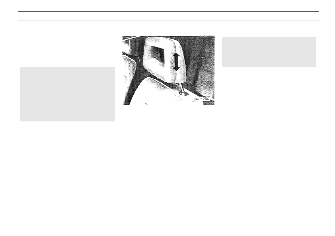
HEAD RESTRAINTS
To ensure proper installation the anchor
fittings or fitting assemblies should be
installed or repositioned by your Audi
dealer.
WARNING
§ Child restraint anchorages are
designed to withstand only those
loads imposed by correctly fitted child
restraints. Under no circumstances
are they to be used for adult seal belts
or harnesses.
§ Do not mount two child restraint
seats on one anchor point.
WARNING
Do not drive the vehicle without the
head restraints provided. Head
restraints are designed to help reduce
injuries.
The padded head restraints on the front
seats are adjustable.
Position front seat head restraints
according to the occupant's height. Only
properly positioned head restraints,
together with the use of safety belts offer
effective protection.
§ For height adjustment, grasp firmly
with both hands and pull up or push
down.
§ For maximum protection the upper
edge should be at eye level.
22
Page 25
SEATS
WARNING
§ For driver's and passenger's
protection make sure front seats are
securely latched in place,
§ Do not adjust the seat while the
vehicle is in motion. The seat may
move unexpectedly which could
cause sudden loss of vehicle control
or personal injury. .
§ Never store items under the seats.
This could interfere with the seat
adjustment.
§ The front seats should be adjusted
before fastening the safety belts.
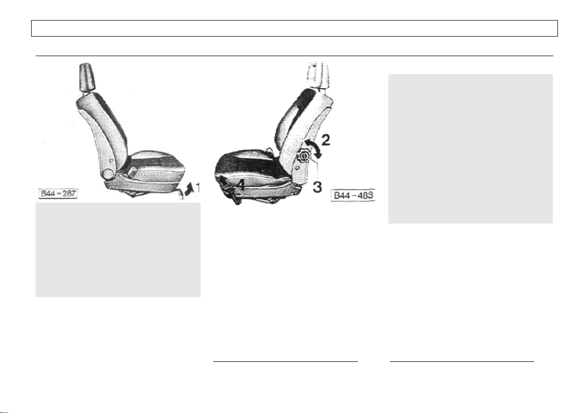
Manually adjustable seats*
1 – Forward and backward adjustment
§ Pull lever in front of seat.
§ Slide seat to desired position.
§ Release the handle and move seat
slightly back and forth to make sure it is
securely locked into position.
2 – Seatback adjustment
Turn wheel at inboard side of seat
cushion, with your body weight taken off
the seatback.
*
where applicable
CONTROLS AND EQUIPMENT
WARNING
To reduce the risk of serious persona)
injury in an accident, front seat
passengers must never ride in a
moving vehicle with the seatback
reclined. The risk of personal injury
will increase with increasing rearward
angle of the seatback.
Safety belts only offer optimum
protection when the seat back is
upright and belts are properly
positioned on the body. Improperly
positioned safety belts cause serious
personal injury in an accident.
3- Lumbar support adjustment
Adjust the backrest support by turning
the adjuster knob in the backrest adjuster
wheel. More or less support adjusts to
the natural curve of your lower back to
minimize fatigue, especially during long
trips.
On vehicles with electrical seat
adjustment, the lumbar support is
adjusted by turning the adjuster wheel,
not the adjuster knob.
1
USA models only
1
23
Page 26
CONTROLS AND EQUIPMENT
1)
4 – Height adjustment
§ Shift your body weight forward and
pull lever on outer side of seat upwards.
§ Raise the seat by shifting your body
weight forward and lower the seat by
shifting your weight backward.
§ Release the lever to lock the seat at
the desired height.
Height adjustment of head restraints
Head restraints must be adjusted
according to seating height of the
respective occupant. See page 22.
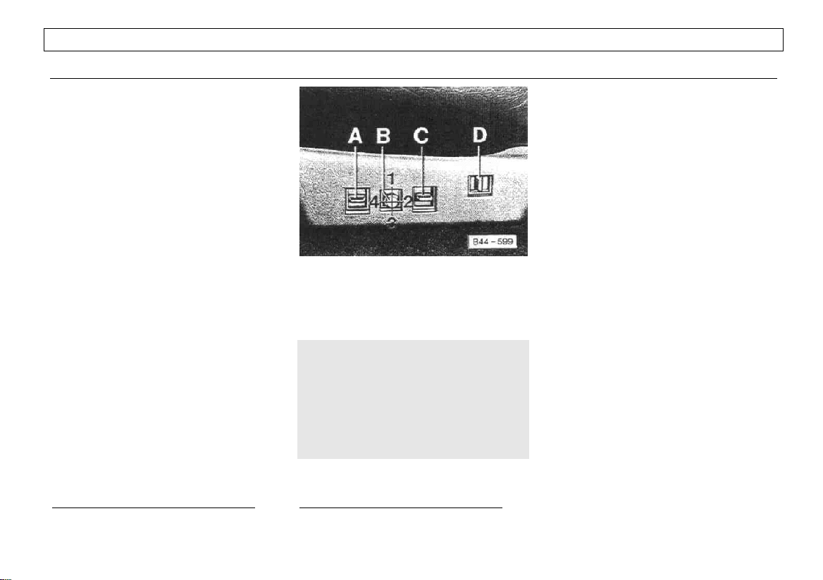
Electrically adjustable seats
The seat adjustment control switches are
located on outboard side of seats. The
controls also work with the ignition off.
*
Switch A
up - seat cushion rises at front
down - seat cushion lowers at front
Switch B
Adjustment control for reach and height:
1 - seat moves up
2 - seat moves rearward
3 - seat moves down
4 - seat moves forward
Switch C
up - seat cushion rises at rear
down - seat cushion lowers at rear
1)
USA models only
24
WARNING
Because the electrical seat
adjustment works also with ignition
key removed, never leave children
unattended in the vehicle.
Unsupervised use of the electrical
seat adjustments may cause serious
injury.
*
where applicable
Switch D
forward - backrest moves forward
rearward - backrest moves rearward
Lumbar support adjustment*
see previous page.
Page 27
CONTROLS AND EQUIPMENT
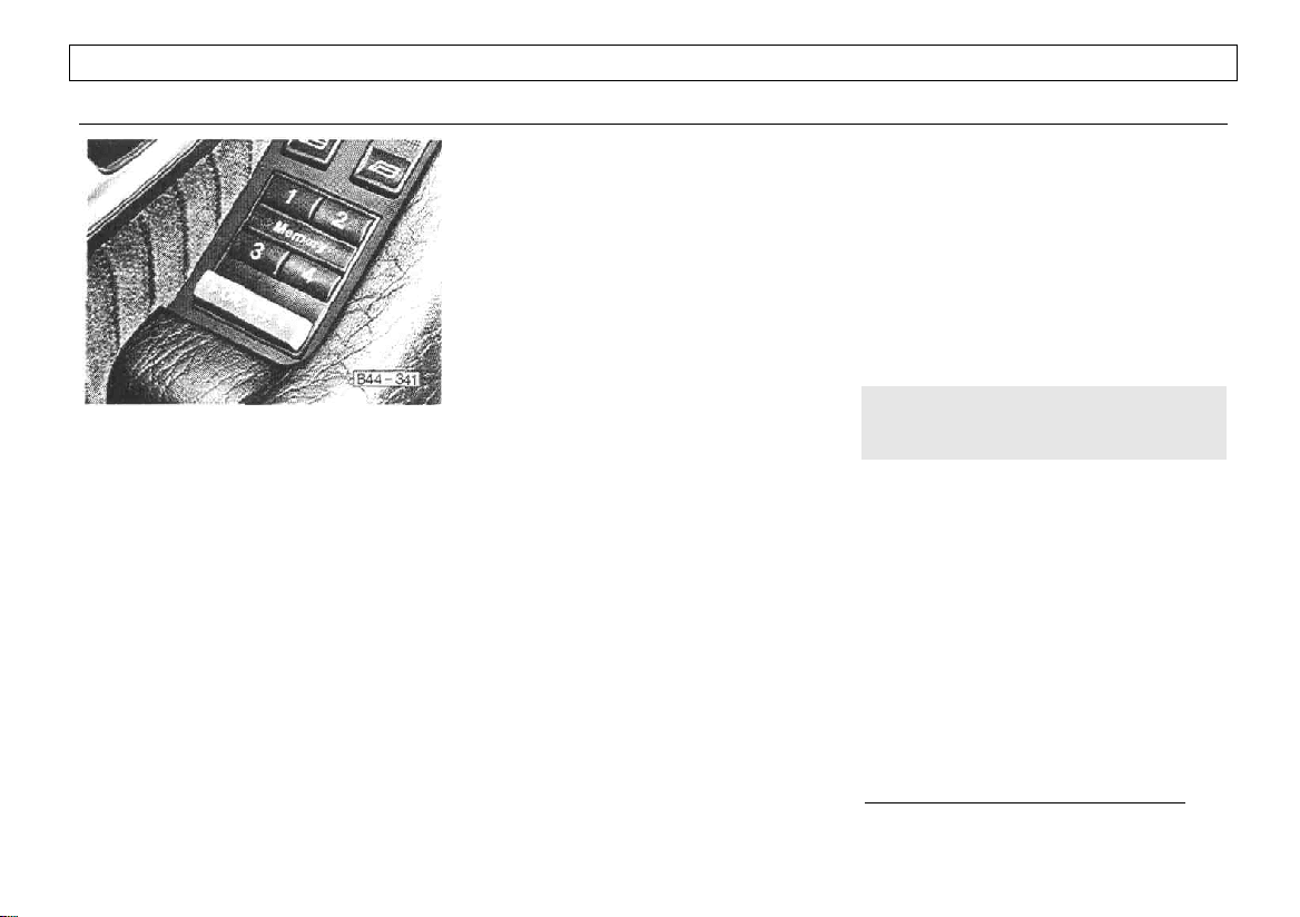
Memory switch controls
For the driver’s convenience, an electric
control panel for storage of 4 different
seat positions has been installed in the
door panel.
ON-OFF switch
During storage and recall, the switch
must be pressed in the "ON" position.
In case of a malfunction, switch the
memory system off by pressing the
switch to the "OFF" position. Have
your Audi dealer locate and correct the
problem. Until then, use switches on
outboard side of seat only.
To store seat position in memory
Adjust seat with controls on outboard
side of seat. Depress and hold memory
bar and depress one of the 4 buttons to
store the desired position. Each
successive storage under the same
button cancels the previous one.
To recall seat position from memory
With door open or within approximately
30 seconds after closing door, briefly
push the desired recall button. The seat
will adjust automatically to the stored
position.
With doors closed, hold recall button
depressed until seat has reached the
stored position.
WARNING
Do not recall seat position from
memory while the vehicle is in motion.
Electrically heated seats
*
With ignition on the backrests and seat
cushions of the front seats and the left
and right seating position of the rear seat
bench* can be heated electrically. See
page 59 for details.
*
where applicable
25
Page 28
CONTROLS AND EQUIPMENT
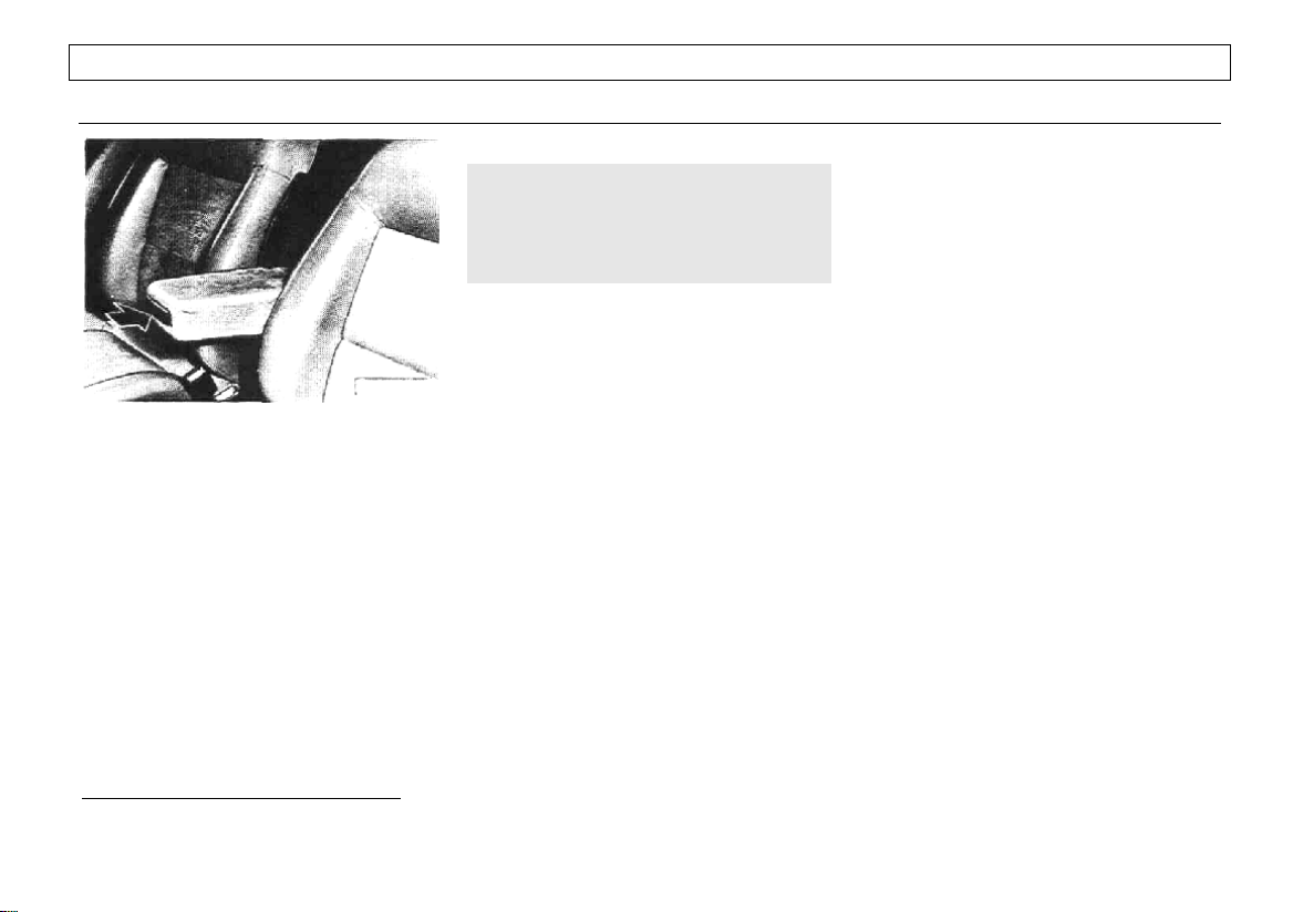
Center arm rest*
§ To fold up, swing the armrest up
until it locks in place.
§ To fold down, push in the button
(arrow) and swing armrest alt the way
down.
§ To adjust height, pull armrest up
until it is in the desired position.
WARNING
The armrest can restrict the driver's
movement when it is pulled down.
Therefore fold up the armrest when
driving in urban traffic.
Armrest for car telephone* – see page
76.
*
where applicable
26
Page 29
FILLER PANEL HEADPHONE CONNECTION*
CONTROLS AND EQUIPMENT
WARNING
§ The filler panel between the rear
seat and the rear window must not be
used for storage, even for small and
light items.
§ During sudden stops, stored
articles may fly forward causing injury
to vehicle occupants.
§ Even small objects can obstruct
the rear vision necessary for safe
driving.
§ Stored articles chafing against
the rear window can damage the
defroster wires.
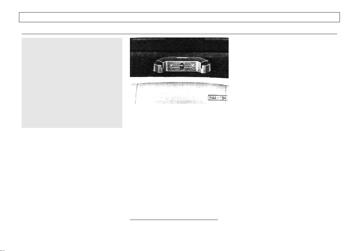
With certain types of radio there is a
headphone connection on the filler panel
that enables the rear passengers to listen
through either the rear loudspeakers or
headphones. A selector switch is provided on the headphone connection:
*
switch in upper position:
loudspeakers
switch in lower position:
headphones
Volume is controlled in the normal way
with the volume and/or fader controls on
the radio.
Suitable headphones can be obtained
from Audi dealers.
*
where applicable
27
Page 30
CONTROLS AND EQ
UIPMENT
SKI SACK*
*
By using the ski sack
skis or other long objects safely and
without soiling or damaging the vehicle
interior.
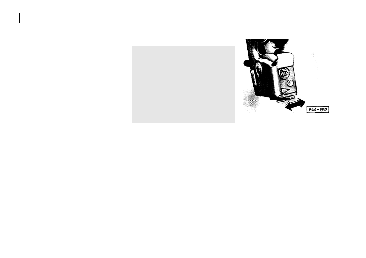
Loading the ski sack
The ski sack is accessible from the rear
seat,
, you can transport
§ Fold out center armrest in the rear
seat backrest. Remove if desired (see
next page).
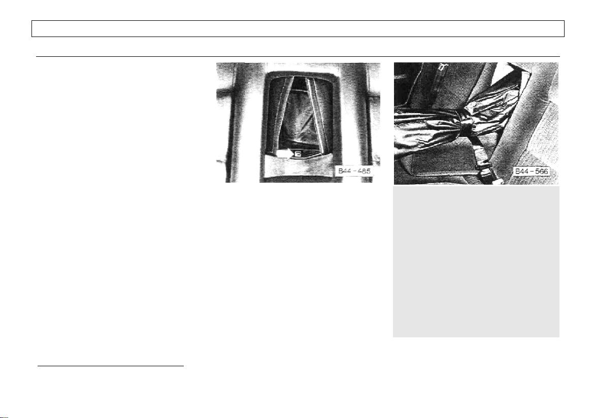
§ Open the Velcro fastener. Push the
release button for the flap (see illustration
and arrow}.
§ Pull out and unfold the ski sack.
§ Open the zipper in the ski sack,
reach in and push the flap upwards all
the way. The flap will be held open by a
magnet.
§ Open the luggage compartment lid
and clear a space in the center.
§ Load skis or similar objects through
the luggage compartment into the interior
of the vehicle.
§ Secure the ski sack using the center
lap belt as shown in the illustration, right
column.
§ Pull the seatbelt out and wrap it
once from underneath around the ski
sack.
*
where applicable
28
- insert the belt tongue into the buckle. To
tighten, pull the belt on the other end and
allow the excess length of the belt to
retract.
Stowing the ski sack
§ Reach through the zipper opening
and close the flap.
§ Fold the ski sack and stow it away.
Close the Velcro fastener.
Note
Do not fold and stow away the ski sack if
it is damp (for example, snow melting
from skis). A water drain is provided on
the end of the ski bag for this purpose.
WARNING
The ski sack is intended only for the
transportation of skis and other light
objects. To reduce the risk of serious
personal injury never transport heavy
or pointed objects in the ski sack.
When braking rapidly or during an
accident the load could be displaced
and cause injury to occupants. Sharp
edges on the load must be covered for
protection. Always fasten the center
lap belt tightly around the sack and its
contents (see illustration and description)
Page 31

Removing and reinstalling center
armrest
§ The center armrest can be taken out
for convenience when using the ski sack.
§ Push aside the backrest upholstery
on each side of the armrest to expose
the armrest mountings.
§ Press back the catch (arrow) on
each side and lift out the armrest.
When reinstalling the armrest, push it
down into its mountings. Make sure that
the pins engage in the catches properly.
CONTROLS AND EQUIPMENT
29
Page 32

CONTROLS AND EQ
UIPMENT
LUGGAGE COMPA R TM
Cargo weight should be located in the
luggage compartment as far forward as
possible.
WARNING
T EN
§ To help prevent poisonous
exhaust gas from being drawn into the
vehicle, always keep the rear lid
closed while driving. Therefore, do not
transport objects larger than those
fitting safely into the luggage area.
To reduce the risk of personal injury
during a collision or sudden
maneuver:
§ Take extra care when stowing
articles in the vehicle, whenever
possible stow articles in the luggage
compartment
§ If it is necessary to stow luggage
or other items inside the passenger
compartment, be sure that they
cannot fly forward in an accident or
sudden maneuver and injure
occupants.
§ Never exceed the Gross Axle
Weight Rating or the Gross Vehicle
Weight Rating which are specified on
the safety compliance sticker located
on the left door jamb. Exceeding
permissible weight ratings can result
in vehicle damage, accidents and
personal injury. See also page 165.
Storage space for small items
The covers of the left and right wells in
the trunk can be folded up to stow small
items. In the Wagon/Avant, a small
storage compartment is behind the right
side trim in the luggage compartment.
Expanding luggage compartment
(Wagon/Avant only )
The rear seatback is divided into two
sections which can be folded forward
together or individually to increase the
loading surface of the luggage
compartment.
§ Press the release lever forward on
the left or right of the seatback (arrow)
and fold the seatback down onto the seat
cushion.
§ On vehicles with rear head
restraints, these do not have to be
removed beforehand.
When the seatback is returned to its
normal position, make sure that the
catches on the seatback engage
properly.
30
Page 33

To fold cover
§ Pull both ends of the rod out of the
recesses and push cover in evenly in a
straight line towards seatback until stop.
To remove
§ Fold rear seatback forward.
§ Push down both covers on guide
rails.
Luggage compartment cover
(Wagon/Avant only )
To unfold cover
§ Pull luggage compartment cover out
of guide rails evenly and in a straight line.
§ Pull folded cover back evenly until
both ends of rod A engage in the rear
portion of the guide rails with an audible
click.
§ Press both ends of rod B into the
retainers on the side trim.
CONTROLS AND EQUIPMENT
To install
§ Fold rear seatback forward and push
down both covers on guide rails.
§ Take up position on the rear seat
and insert rods on cover in guide rails
and push towards the rear.
§ Lift up both caps on guide rails.
§ Pull front rod forward until it engages
in both covers
31
Page 34

CONTROLS AND EQUIPMENT
WARNING
§ The luggage compartment cover
between the rear seat and the rear
window must not be used for storage,
even for small and light items.
§ During sudden stops, stored
articles may fly forward causing injury
to vehicle occupants.
§ Even small objects can obstruct
the rear vision necessary for safe
driving.
§ Stored articles chafing against
the rear window can damage the
defroster wires
Cargo floor (Wagon Avant only }
For maximum capacity, or for gaining
access to the spare wheel well, the cargo
floor can be lifted (arrow) and folded
forward towards the rear bench seat.
To remove
§ Fold cargo floor forward.
§ Unscrew the upper screw in
mountings on each side under the cargo
floor.
§ Lift out cargo floor.
To install
§ Put folded cargo floor into place.
§ Engage mountings with lower
screws on each side under the cargo
floor.
§ Insert and tighten upper screws on
mountings.
§ Unfold cargo floor as desired.
32
Page 35

CONTROLS AND EQUIPMENT
FLOOR MAT FASTENERS PEDALS
Floor mat fasteners are installed in the
footwells of the front seats.
Your vehicle is equipped with original
Audi floor mats, which must be attached
to these fasteners (see illustration). This
will prevent the floor mats from sliding
into positions that could interfere with the
safe operation of your vehicle.
WARNING
Do not install additional floor mats on
top because you will not be able to
fasten them down. If you remove the
floor mats for cleaning, be sure to
fasten them securely again when
reinstalling.
For replacement your Audi dealer will be
glad to help you choose suitable floor
mats for your vehicle.
WARNING
The movement of the pedals must
never be obstructed by a floor mat or
any other object:
§ In case one of the two brake
circuits fails, increased brake pedal
travel is required to bring your vehicle
to a full stop.
§ It should always be possible to
depress the clutch and accelerator
pedals fully.
§ All pedals must be able to return
freely to their normal positions.
Only use floor mats which leave the
pedal area free and can be secured
with floor mat fasteners.
33
Page 36

CONTROLS AND EQUIPMENT
BRAKES
Functioning of brake system
Your vehicle is equipped with a power
assisted hydraulic dual circuit Anti-Lock
brake system (ABS) with disc brakes at
the front and rear. Both circuits function
independently. Each brake circuit
operates one front and rear wheel
diagonally. On quattro models brake
circuits are split front and rear. This
design, together with other front axle
features, also helps to keep you on a
straight course when braking.
For further information regarding AntiLock brake system see next page.
In the unlikely event of hydraulic failure of
one circuit, push the brake pedal down
firmly and hold it in that position. A
mechanical linkage activates the second
circuit, and you will be able to bring the
vehicle to a stop.
WARNING
Failure of one brake circuit wit! impair
the braking capability resulting in an
increased stopping distance.
If one brake circuit fails, the other will still
operate. However, you will notice an
increased pedal travel when you step on
the brake. Should you encounter such
experience, bring your vehicle safely to a
full stop.
Avoid driving the vehicle and have it
towed to the nearest Audi dealer or
qualified workshop.
Brake operation and brake warning
light
Make it a habit to check the operation of
your brakes before driving. The brake
warning light will light up if the parking
brake is pulled and/or the brake fluid
level or the hydraulic brake booster
pressure is too low. For more details see
"Brake warning light" on page 50.
Keep in mind that the braking distance
increases very rapidly as the speed
increases. At 60 mph or 100 km/h, for
example, it is not twice but four times
longer than at 30 mph or 50 km/h. Tire
traction is also less effective when the
roads are wet and slippery. Therefore,
always maintain a safe distance.
Brake booster
The brake booster is supplied with
pressure from the hydraulic pump via the
hydraulic pressure reservoir. If the engine
is switched off or if the hydraulic pressure
supply should fail, the operating pressure
is retained. However, since the capacity
of the pressure reservoir is limited, it will
provide enough pressure for only a few
braking applications. If this should occur,
contact your authorized Audi dealer for
assistance.
WARNING
When the vehicle is moving with the
engine not running or in case of a
hydraulic system failure, more force
on the brake pedal is required to bring
the vehicle to a stop.
34
Page 37

*
Anti-lock brake sy stem (A B S
The ABS contributes effectively to vehicle
control, since it prevents the wheels from
locking when the brakes are applied.
This means that the vehicle remains
steerable and is less inclined to skid.
If an individual wheel begins to rotate too
slowly in relation to vehicle speed and
tends to lock, the ABS automatically
reduces brake pressure to prevent that
wheel from locking.
This automatic adjustment process will
cause a slight vibration of the brake
pedal and some noises to alert you that
vehicle speed must be adapted to
existing road and traffic conditions.
WARNING
Although the ABS is very effective
always remember that braking
capability is limited by tire traction.
Always adjust your driving speed
according to the road and traffic
conditions. Do not let the extra safety
afforded by the ABS tempt you into
taking extra risks. The ABS cannot
overcome the laws of physics.
*
where applicable
)
Every time the engine is started, the ABS
switches on automatically.
The ABS can be switched off and on by
depressing the main switch.
Normally the ABS should always be
switched on. Under certain conditions,
however, it may be advisible to switch the
ABS off manually. For further information
see page 60.
If the ABS is not functioning properly, a
warning light will come on. See page 49
for additional details.
Note
When the rear differential lock is
engaged, the ABS will switch off as the
system is now unable to monitor
separately the rotation of the rear wheels.
As long as the differential lock is
engaged, the brake system will operate
normally. The ABS will switch on again
automatically when the differential lock is
disengaged or as soon as the vehicle
exceeds a speed of 15 mph or 25 km/h.
CONTROLS AND EQUIPMENT
Conditions affecting braking
efficiency
Moisture or road salt
WARNING
§ Under certain climatic and
operating conditions such as passing
through water, driving in heavy rain or
after washing the vehicle the
effectiveness of the brakes can be
reduced, in winter ice can accumulate
on the brake pads, linings, discs and
drums. Cautiously apply brakes for a
test. Brakes will dry, ice coatings will
be cleaned off after a few cautious
brake applications.
§ Driving for an extended period of
time on salt covered roads without
using your brakes can also affect
braking efficiency. The accumulated
salt coating must be cleaned off the
brake discs and brake pads by a few
cautious brake applications.
§ Do not "ride the brakes" by
resting your foot on the pedal when
not intending to brake. This may
cause the brakes to overheat,
premature wear and increased
stopping distance.
35
Page 38

CONTROLS AND EQUIPMENT
§ Before descending a steep grade,
reduce speed and shift transmission
into a lower gear or driving position to
control speed. Do not ride the brakes
or hold the pedal down too long or too
often. This could cause the brakes to
get hot and diminish braking
efficiency.
New brake pads or linings
§ New brake pads and lining do not
have optimum friction properties and
must be "broken in" during the initial 100
to 150 miles (150 to 200 kilometers) of
normal city driving. You can compensate
for this by applying more pressure on the
brake pedal. This also applies later when
new pads or linings are installed.
Brake fluid level
§ If the brake fluid level is too low,
malfunctions or even a failure in the
brake system could result Therefore, it is
important to check your brake fluid level
regularly. See page 112 for more details.
Low brake fluid is indicated by the brake
warning light (see page 50).
Failure of one brake circuit
If the brake pedal travel should suddenly
increase, one of the brake circuits may
have failed, Should this happen, you will
be able to bring your vehicle safely to a
stop, however, you will have to push
harder on the brake pedal and it will take
a longer distance to stop the vehicle.
Contact your authorized Audi dealership
for assistance.
Brake wear
The brakes on our automobiles are still
subject to wear depending largely on
operating conditions and driving habits.
On vehicles which are driven mostly in
stop-and-go city traffic or which are
driven hard, the brake linings should be
checked by your authorized Audi dealer
more often than specified in the
Maintenance brochure.
Front spoiler
If you install a front spoiler on your
vehicle, be sure the air flow to the front
brakes is not obstructed, otherwise the
brake system could overheat.
36
Page 39

Parking brake lever
The parking brake lever is located
between the front seats.
§ To set the parking brake, pull the
lever up until strong resistance is felt.
With the ignition on. the brake warning
light will light up.
§ Depress brake pedal and hold while
releasing parking brake. To release the
parking brake, pull the lever slightly up,
depress the release button (arrow), and
then push the lever all the way down.
When the parking brake is fully released,
the brake warning light will go out.
CONTROLS AND EQUIPMENT
WARNING
§ Release the parking brake fully. A
partially engaged brake will overheat
the rear brakes, reduce their effectiveness and cause excessive wear.
§ Always set the parking brake
when parking your vehicle. Move the
selector lever to "P" (Automatic
transmission) or move the gearshift
lever to "R" or "1" (Manual transmission). On hills also turn the wheels
toward the curb.
37
Page 40

CONTROLS AND EQUIPMENT
MANUAL TRANSMISSION
Gearshift lever
Start engine with gearshift lever in
Neutral, clutch pedal depressed.
Always depress the clutch pedal fully
when changing gears. Do not hold the
vehicle on a steep hill with the clutch
pedal partially depressed. This may
cause premature clutch wear or
damage.
Resting your hand on the shift lever
knob while driving will cause
premature wear in the transmission.
The five forward gears and the reverse
gear are arranged as illustrated.
Drive in 5th gear for optimum fuel
economy when cruising. However if more
acceleration is required (when passing
for example) shift down.
WARNING
To down-shift from 5th gear to 4th
gear, do not move shift lever to the left
to avoid shifting accidentally into 2nd
gear, which wilt suddenly increase
engine speed and may cause damage
and loss of vehicle control.
Reverse
Only shift into Reverse when the
vehicle is not moving.
To engage Reverse, move lever to right,
press down and pull back.
When shifting from 5th gear to R, move
gearshift lever to the 3rd/4th gear level
first.
Back-up lights go on when you engage
Reverse gear with ignition on.
38
Page 41

AUTO MATIC TRANSMISSION
CONTROLS AND EQUIPMENT
Automatic Shift Lock (ASL) and
Warning buzzer
Automatic Shift Lock
Your Audi is equipped with an Automatic
Shift Lock (ASL). The ASL is an
electromechanical device that locks the
selector lever in the P-Park and
N-Neutral positions when the ignition is
on. The ASL prevents you from moving
the selector lever out of the Park and
Neutral positions unless you step on the
foot brake at the same time.
The shift lock in the N-Neutral position
has a time delay of one second which
prevents the selector lever from locking
when it is moved briefly through the N
position (for instance from R to D). The
shift lock only locks the selector lever if it
is left in the N position for more than
about one second without the brake
pedal being depressed.
In N-Neutral position the shift lock is
automatically deactivated when driving
faster than approximately 3 mph/5 km/h.
The ASL will not affect normal operation
of your car.
Warning buzzer
A warning buzzer will sound when you
open the driver's door with the selector
lever left in any other but P-Park posi-
tion. The warning buzzer will go off as
soon as the selector lever is moved to
the P-Park position.
Selector lever positions
P-Park
Engage Park only when the vehicle is
stationary. Therefore, when parking your
vehicle, apply the parking brake first, and
then move the selector lever completely
to position P. To do this depress the
selector lever and push it through R to
P. When the R-Reverse position is
selected, you can shift to position P
without depressing the selector lever.
The transmission is then mechanically
locked.
Before you move the selector lever
from the P-Park position to R-Reverse
or any other position, you must
always
apply the foot brake before and while
depressing the selector lever.
Shift out of the Park position, before
releasing the parking brake.
When the vehicle is parked on a steep
hill, shifting out of Park may be a little
harder. This is due to the vehicle's weight
exerted on the transmission.
R – Reverse
Reverse should be selected only when
the vehicle has come to a full stop and
the engine is running at idle speed.
Before you move the selector lever to
the reverse position you have to
depress the selector lever.
N-Neutral
Shift to this position for standing with
brakes applied.
When the vehicle is stationary or at
speeds below 3 mph/5 km/h, you must
always apply the footbrake before and
while moving the lever out of NNeutral.
Do not use Neutral for coasting downhill. Coasting downhill with the transmission in Neutral and the engine not
operating will result in damage to the
Automatic transmission.
39
Page 42

CONTROLS AND EQUIPMENT
D – Normal driving position
Position D is the normal driving position
for city and highway driving. It ranges
from zero to top speed, and all three
gears shift automatically, depending on
engine.load and driving speed.
2 – Position for hilly stretches
This position is to be used for mountain
driving or slow driving, and also when
you want to make use of the engine's
braking effect.
In "2", only the first and second gears will
engage automatically.
The road speed must not exceed 65 mph
or 105 km/h. Therefore, only shift down
into position "2" when vehicle speed
is below this speed. It is not necessary
to let up on the accelerator.
1 – Position for steep hills
This position is to be used for mountain
driving or slow driving. It also provides for
maximum engine braking effect. To
engage this gear depress the selector
lever first. In "1" the transmission will
stay in first gear and will not upshift.
The road speed must not exceed 30 mph
or 50 km/h. Only shift down into "1"
when vehicle speed is below this
speed.
40
In position 1, the cruise control is
inoperative.
WARNING
Do not shift to a lower driving position
until vehicle speed has dropped below
specified limits otherwise engine
speed will suddenly increase and may
cause engine damage and loss of
vehicle control.
Driving the automatic transmission
Observe the instructions for the break-inperiod-listed on page 81.
Starting the engine
The selector lever must be in Neutral or
Park. If one of the driving positions is
engaged a safety switch will prevent the
engine from being started.
Emergency starting
Your Audi with Automatic Transmission
cannot be started by pushing or
towing.
If engine does not start because of
discharged battery, the vehicle can be
started with jumper cables. Refer to
"Emergency starting with jumper cables".
Should the engine fail to start consult
your nearest Audi dealer.
WARNING
§ Always apply the foot brake
before selecting a driving position
while the vehicle is stationary.
Your vehicle is equipped with an Automatic Shift Lock (ASL). To move the
selector lever out of the P-Park and
out of the N-Neutral position (when
stationary or at speeds below 3 mph/
5 km/h) you must depress the brake
pedal.
When the selector lever is in a driving
position, the vehicle may creep even
at idle speed. Therefore, do not release the parking brake or foot brake
until you are ready to move, because
power is transmitted to the wheels as
soon as a driving position is engaged,
§ Do not accelerate while selecting
a driving position. At this time the engine must run at idle speed so that no
undue stress will be placed on the automatic clutches in the transmission.
§ Never have any driving position
engaged when checking under the
hood. Make sure the selector lever is
securely locked into the P position
with the parking brake firmly set.
Otherwise, any increase in engine
speed may set the vehicle in motion,
even with the parking brake applied.
Page 43

CONTROLS AND EQUIPMENT
§ Never shift into Reverse (R) or
Park (P) when the vehicle is in motion.
§ Do not remove the key from the
ignition/steering lock until you have
parked the vehicle, otherwise the
steering wheel will lock,
§ If the selector lever is uninten-
tionally moved into Neutral (N) while
driving, take your foot off the accelerator pedal and wait until the engine
speed has dropped to idle before selecting a driving position.
Maneuvering
When alternating between forward (D}
and reverse (R) -for instance, while
maneuvering the vehicle into a tight
parking space – only shift when the
vehicle has come to a full stop and the
engine is running at idle speed.
Parking
When parking your car, move the
selector lever into the P-Park position.
Apply the parking brake and switch off
the ignition.
Do not leave the selector lever in the
Neutral position or any driving position.
The warning buzzer will sound when you
open the driver's door with the selector
lever not in the P-Park position. If you
park on a hill, turn your front wheels
toward the curb.
Stuck in snow, mud or sand
When alternating between forward (D)
and reverse (R) in an effort to free the
vehicle, depress the accelerator pedal
slightly while the transmission is in gear,
and release the accelerator pedal while
shifting. Do not race the engine and
avoid spinning the wheels. Do not
repeat "rocking" back and forth with
wheels spinning at high engine speed
and heavy throttle, as serious damage
may be caused to the automatic
transmission and other critical parts.
Kickdown device
The kickdown device gives maximum
acceleration when the accelerator pedal
is pressed down past the full throttle
position. Depending on road speed and
engine speed, the upshift is either
delayed (forced throttle) or the
transmission changes down into the next
lower gear.
WARNING
Be careful when using the kickdown
on slippery roads. Rapid acceleration
may cause skidding.
Stopping
§ When stopping briefly, at a traffic
light for example, it is not necessary to
move the selector lever to Park or
Neutral. Simply step on the foot brake.
To start again, remove your foot from the
foot brake to the accelerator pedal and
carefully accelerate.
§ The driving positions must never be
used for holding the vehicle at rest uphill.
Always use your foot brakes when
stopped on inclines.
WARNING
§ Never get out of the driver's seat
when the engine is running and the
selector is not securely locked in the
"P" position.
§ If you must leave the vehicle
move the selector fever securely into
the "P" position and apply parking
brake firmly.
Towing
if the vehicle has to be towed at any time,
you must read the instructions in the
section "Emergency towing" on page
148.
41
Page 44

CONTROLS AND EQUIPMENT
STEERING LOCK/ IGNITION/ STARTER SWITCH
Switch positions
1. - Ignition off/steering can be locked.
Pull out the key and turn steering
wheel until it locks.
WARNING
§ This position only locks the
steering wheel and not the shift
control lever. Sudden and unexpected
vehicle movement may occur if the
shift control lever is moved out of P
(Park) (automatic transmission) or out
of gear (manual transmission) and the
parking brake is not firmly set.
§ Never remove key from steering
The steering is equipped with an antitheft ignition lock.
lock or turn key off white the vehicle is
moving. The steering wheel will lock,
causing loss of control.
2. - Ignition on/steering free. If it is
difficult to turn the key from position 1
to 2, gently move the steering wheel
until the key turns freely.
3. - Starter engages.
4. - Key returns to position 2 as soon as
it is released.
"Starting procedures" see following
pages.
In position 3, the power supply to
headlights, windshield wipers, blower
motor and rear window defogger is
temporarily interrupted to conserve
battery power.
Before the starter can be operated again
the key must be turned back to position 1.
The non-repeat lock in the ignition switch
prevents the starter from being operated
when engine is running as this could
damage the starter.
In position 2 and 3 several warning/
indicator lights will come on. Refer to
"Warning/indicator lights" for details.
Chime
If you leave the key in the ignition/
steering lock, the chime will sound when
the driver's door is opened. This is your
reminder to remove the key.
42
Page 45

CONTROLS AND EQUIPMENT
STARTING PROCEDURES STOPPING ENGINE
WARNING
§ Fasten safety bells before driving.
§ Never start or let the engine run in
a confined or enclosed, unventilated
area. Exhaust fumes from the engine
contain carbon monoxide, which is a
colorless and odorless gas. Carbon
monoxide can be fatal if inhaled.
§ Never leave engine idling unat-
tended. An unattended vehicle with a
running engine is potentially hazardous.
§ Do not park or operate the vehicle
in areas where the hot exhaust system
may come in contact with dry grass,
brush, fuel spill or other material
which can cause a fire.
§ Do not leave engine unattended at
idle. When starting engine, be ready to
drive off immediately. Maintain moderate speed until your engine is completely warm. Remember that your engine performs best at operating temperature.
Automatic Transmission
Engine will only start with selector lever
in Neutral or Park.
Manual Transmission
Start with gearshift lever in Neutral,
clutch pedal depressed, so that the
starter only has to crank the engine.
Starting engine
§ Do not depress accelerator pedal
while starting. This applies at any outside
temperature.
§ As soon as the engine starts,
release the ignition key.
§ If the engine does not start the first
time or stalls, turn the ignition off and
restart.
§ Operate the starter for no more than
10 seconds.
§ Allow about 30 seconds between
each starting attempt.
§ When starting a very hot engine, it
may be necessary to slightly depress the
accelerator pedal after starting the
engine.
If the engine does not start, the fuse for
the electric fuel pump or the fuses for the
engine timing may be blown – see page
136.
Do not stop engine immediately after
hard or extended driving. Keep engine
running for about two minutes to
prevent excessive heat build-up.
WARNING
§ Before you check anything in the
engine compartment, stop the engine
and let it cool down. Hot components
can burn skin on contact.
§ Never touch the radiator fan
blades. They will rotate spontaneously
when the thermos witch turns the fan
on. The radiator fan switches on
automatically when the coolant or
engine compartment reaches a certain
temperature and will continue to run
{even with the ignition off) until the
temperature drops. This may take up
to about 10 minutes.
43
Page 46

CONTROLS AND EQUIPMENT
INSTRUMENT CLUSTER
page
1 - Coolant temperature gauge....... 45
2 - Digital clock ................................ 45
3 - Tachometer ................................45
4 - Speedometer/odometer with reset
knob for trip odometer................ 46
44
page
5 - Fuel gauge ................................. 46
6 - Engine oil temperature gauge.... 46
7 - Engine oil pressure gauge......... 46
8 - Voltmeter.................................... 46
page
9 - Instrument illumination..............46
- Auto-Check System knob.........53
- Setting knob for the
digital clock...............................45
10 - Warning/indicator lights............47
11 - Auto-Check System display.....52
12 - Trip computer display...............56
Page 47

CONTROLS AND EQUIPMENT
1 – Coolant temperature gauge
When the ignition is switched on the
needle in the coolant temperature gauge
will indicate the temperature of the
coolant.
Engine cold
Avoid high engine speeds and heavy
throttle application when the needle is
still on the left of the dial.
Normal temperature
During normal running the needle will
settle somewhere in the middle of the
dial.
If the engine is working hard at high
ambient temperatures, the needle may
also go further to the right, but this is no
cause for concern provided that the
coolant temperature warning light
does not start flashing.
Warning light
If the coolant warning light (see page 48)
or the light in the Auto-Check System
{see page 54) lights up while driving, the
engine may be overheated because of
low coolant level. Move the vehicle a safe
distance off the road, stop the engine and
lift the emergency flasher switch lever up.
*
where applicable
*
WARNINGS and further details see
page 54 and 113.
Note
Do not install accessories (additional
lights or insect screens, for example)
on top of the front bumper. They may
restrict engine cooling.
2 – Digital clock
The digital clock is incorporated in the
tachometer dial. Pull out and turn the
knob (see position 9) as follows to set the
time.
§ Turn all the way to the left to set the
hours.
§ Turn all the way to the right to set
the minutes.
The hours or minutes will advance
continuously if the knob is turned and
held.
To set the clock accurately to the second:
§ Turn the knob to the right and hold
until the clock reads one minute before
the time to beset.
§ Turn the knob to the right again
briefly to coincide with a radio time
signal, or when the seconds reading on
an accurate wrist watch reaches a full
minute.
3 – Tachometer
The red area at the end of the scale
indicates the maximum permissible
engine rpm (revolutions per minute) for
all gears after the break-in period. Before
reaching this area, the next higher gear
should be selected or the foot eased on
the accelerator pedal. Earlier shifting
saves fuel and reduces noise.
Shift to the next lower gear when the
engine rpm drops below 1500 rpm.
45
Page 48

CONTROLS AND EQUIPMENT
4 – Speedometer/Odometer
The speedometer indicates road speed.
The odometer indicates the distance
driven.
USA models: Miles
Canada models: Kilometers
To record a distance, reset the trip
odometer to zero by pressing the button.
The last digit in red indicates 1/10 of a
mile or kilometer.
5 – Fuel gauge
The needle in the fuel gauge will indicate
the fuel level in the tank shortly after the
ignition is turned on or the engine is
running.
The fuel tank capacity is 21 gal/80 liters.
When the needle reaches the red area,
there is a reserve of 3.2 USAgai/12 liters
of fuel left in the tank. Time to refuel.
6 – Engine oil temperature gauge
Engine oil temperature is measured in
degrees Celsius from 60 °C (140 °F) to
170 °C (338 °F). With needle around
60 °C, do not accelerate under full load.
If the needle moves into the upper zone
in exceptional cases, the engine speed
must be reduced. The needle should
then return to the normal zone.
If the needle stays in upper zone, stop
the vehicle, switch off the engine and
check the oil level. If the oil level is
correct and the oil pressure warning light
does not flash when the engine is
started, you can drive on to the next Audi
dealer but do not run engine at high
speeds.
7 – Engine oil pressure gauge
Oil pressure in the engine is shown in
bar. Should engine oil pressure drop
suddenly (below 1.8 bar) while driving, a
warning light will flash or three warning
tones will sound and the oil pressure
warning light in the Auto-Check System
will flash.
Pull safely off the road and stop.
Let the engine cool down before
checking the engine oil level. Add engine
oil if necessary.
If engine oil pressure does not return to
normal, do not continue to operate the
vehicle. Have your Audi dealer locate
and correct the cause promptly.
8 – Voltmeter
The voltmeter in the instrument cluster
shows the voltage for the vehicle's total
electrical system. The normal reading
should be between 12 and 15 volts. If the
voltage should drop below 12 volts while
the engine is running, have the electrical
system (battery and alternator) inspected
by your Audi dealer. See also pages 49
and 55.
When starting your vehicle, the voltage
may drop below 8 volts.
9 – Instrument illumination
With the lights switched on, you can
adjust the brightness of the instrument
panel and the center console by turning
the knob in the instrument cluster located
next to the coolant temperature gauge –
see page 44.
10 – Warning/indicator lights
see page 47,
11 – Auto-Check Sy stem
see page 52.
12 – Trip computer
see page 56.
46
Page 49

WARNING/ INDICATOR LIGHTS
CONTROLS AND EQUIPMENT
Your vehicle is equipped with several
important indicator and warning devices
to monitor the continued reliable
operation of your vehicle. Familiarize
yourself with these devices so if one
should come on you know what to do.
Failure to heed applicable warnings and
important vehicle information may result
in serious persona! injury or vehicle
damage.
WARNING
§ Whenever stalled or stopped for
repair, move the vehicle a safe
distance off the road, stop the engine
and turn on the emergency flasher
(see page 65).
§ The engine compartment of any
motor vehicle is a potentially hazardpus area. Before you check anything
in the engine compartment, stop the
engine and let it cool down. Always
exercise extreme caution when
working under the engine hood. Heed
all of the WARNINGS on page 102.
47
Page 50

CONTROLS AND EQUIPMENT
§ Check coolant level. Top up as
necessary (see "Adding coolant", page
114).
- Emission Control
System (ECS)
*
Vehicles without
Auto-Check System
– Coolant temperature/
coolant level
If the light flashes when driving, either the
coolant temperature is too high or the
coolant level in the expansion tank is too
low.
§ Pull off the road, lift the emergency
flasher switch lever up and turn off the
engine and let it cool down. For further
details see "Coolant temperature gauge”
on page 45 and 113.
48
- Engine oil pressure
If this light comes on, it indicates that the
engine oil pressure is too low.
Pull off the road and stop the engine
immediately, let it cool down and
check the engine oil level and add oil,
if necessary.
If engine oil level is normal, but the
light comes on again, do not continue
to operate the vehicle. This could
damage the engine.
Turn the engine off and contact the
nearest Audi dealer for assistance.
The oil pressure warning light is not
an indicator for low engine oil level.
To check the oil level, always use
dipstick (see page 105).
Engine oil pressure and oil
temperature gauge see page 46.
Make it a habit to have the engine oil
level checked with every fuel filling.
see page 51.
*
where applicable
Page 51

CONTROLS AND EQUIPMENT
Ü Þ – Turn signal and
emergency flasher
see page 62 and 65.
– Alternator warning light
This light comes on when the ignition is
turned on and goes out after the engine
is started. If the light does not go out after
starting and reving-up the engine
momentarily or lights up while driving,
there may be a malfunction in the
electrical system or the V-belt driving the
alternator may be loose or broken.
In this case you may continue driving,
because the cooling system is still
operative. However, since the battery is
no longer charged, switch off all
unnecessary electrical equipment and
contact the nearest Audi dealer.
The voltage in the electrical system is
displayed on the voltmeter. See page 46
for additional details.
ANTI LOCK OFF-Warning light
This light will come on when the ignition
is turned on. The light will go out after the
engine is started, the alternator warning
light has gone out and a check in the
electronic part of the system has been
completed.
On the Audi 100 quattro, the warning
light goes out only when the differential
lock is disengaged.
If the light does not go out, or if it comes
on while driving with unlocked differential
(Audi 100 quattro) and the ABS switch
on, there may be a malfunction in the
system. Test the system's function at
moderate driving speed by switching the
main switch off and on. If the ANTI LOCK
OFF warning light remains on, there is a
malfunction in the system. The vehicle
can then be stopped with the standard
brake system only.
Have your Audi dealer locate and correct
the problem as soon as possible. For
details see pages 35 and 60.
– High beam indicator light
The indicator light lights up when the high
beams are switched on or when the
headlight flasher is used.
Refer to "Turn signal/headlight dimmer
switch lever" on page 62 for details.
49
Page 52

CONTROLS AND EQUIPMENT
BRAKE
The light comes on when the ignition is
turned on and goes out after the engine
is started and the parking brake is fully
released. This is your assurance that the
brake warning light functions properly.
If the brake warning light does not light
up when turning the ignition on, or setting
the parking brake, there may be a
malfunction in the electrical system. If
this is the case, contact your Audi dealer.
If the light remains on after the engine is
started and the parking brake is fully
released, or if it should come on while
you are driving, it may be due to one of
the following reasons;
1)
2)
– Brake warning light /
power steering
§ Brake fluid level is too low.
§ Insufficient hydraulic fluid in the
reservoir.
§ Pressure for the hydraulic brake
booster is too low.
1)
USA models only
2)
Canada models only
50
Stop the vehicle and check brake fluid
level and hydraulic fluid level.
If the brake fluid in the reservoir or if the
hydraulic fluid has dropped to the "MIN"
mark, drive carefully to the nearest Audi
dealer. Have the cause of flu id loss
located and corrected immediately.
However, if the level of hydraulic fluid is
already well below the "MIN" mark, or if
the reservoir is empty, do not continue to
drive as this would cause serious
damage to the hydraulic system. See
also page 112.
If the brake fluid level is too low, one of
the two power assisted hydraulic brake
circuits may fail. Drive with extreme
caution and only if necessary {see page
34 and112fordetails).
If both fluid levels are normal, the
pressure for the hydraulic brake booster
may be too low. Drive with extreme
caution to the nearest Audi dealer or
qualified workshop to have the entire
brake system checked. Keep in mind that
increased pedal travel and stopping
distance will be necessary.
A malfunction in the power steering
system may also have occurred. You can
continue to steer the vehicle; however,
more effort will be required to turn the
steering wheel (see page 111 for more
details).
WARNING
If the brake pedal travel has in
creased, one of the brake circuits may
have failed. Avoid driving the vehicle
and have it towed to the nearest Audi
dealer or qualified workshop for
repair.
If brake pedal travel has not increased
and braking performance remains
unimpaired, proceed to your nearest
Audi dealer or qualified workshop to
have the braking system in-
For details see "Brakes" on page 34.
– Safety belt warning light
Refer to "Safety belts" on page 15 for
details.
Page 53

AIR
BAG – Air bag system
1)
The indicator light must come on when
the ignition is switched on, and go out
after about 10 seconds.
If the light does not go out, or if it comes
on while driving, this indicates a
malfunction in the Air bag system.
If the indicator light does not come on
when the ignition is switched on, this also
indicates a system malfunction.
If any of these conditions occur, have the
Air bag system inspected immediately by
your Audi dealer. See page 160 for
further details.
1)
USA models only
– Emission Control
System (ECS)
*
Vehicles having this indicator light are
equipped with an on-board diagnostic
system. This system monitors the various
components of your Emission Control.
Each controlled component in your
Emission Control System has been
coded. In case of a malfunction the
respective component will be identified
and the fault stored in the control unit's
memory.
The stored data can be displayed by a
flashing code of the ECS-malfunction
indicator light to assure an accurate
diagnosis.
Your authorized Audi dealer can interpret
the code and make the necessary
correction.
The ECS-malfunction indicator light
comes on when the ignition is switched
on and will go out after the engine is
started. This is to assure you that the
indicator light is functioning properly.
*
where applicable
CONTROLS AND EQUIPMENT
If the light does not go out after starting
the engine or if it should come on while
driving, this indicates that there is a
malfunction in the Emission Control
System. Continue driving with reduced
power and have the cause corrected
promptly by an Audi dealer or a qualified
workshop.
51
Page 54

CONTROLS AND EQUIPMENT
AUTO-CHECK SYSTEM *
The Auto-Check System consistently
monitors certain individual functions and
components of the vehicle as soon as
the ignition is turned on and when the
vehicle is moving.
Malfunctions or urgent repairs are audibly
signaled as well as displayed by red or
yellow light symbols in the instrument
cluster.
You are thus reminded that a problem
exists which should be corrected for your
convenience and safety, and to prevent
the risk of considerable damage to your
vehicle due to certain malfunctions.
The following malfunctions or warnings
can be displayed;
Red Symbols
§ Engine coolant level is too
low/Engine temperature is too high
(moving symbol).
§ Engine oil pressure is too low
(moving symbol).
When the red blinking symbols appear,
three warning tones will sound at the
same time. These symbols represent
DANGER.
* where applicable
Do not continue to operate the
vehicle. The problem must be located
and corrected immediately. Pull off the
road to a safe area, well away from
traffic, stop the engine and operate the
emergency flasher. Use other warning
devices to alert motorists. Contact your
Audi dealer or a qualified workshop.
In the event of multiple malfunctions, the
symbols will blink successively in twosecond intervals. The symbols will
continue to blink until the malfunction is
corrected.
USA Models: If both Warning (yellow
symbol) and Danger {red symbol)
malfunctions have occurred, both the
yellow and the red symbols will blink
alternately.
Canada Models: If both Warning (yellow
symbol) and Danger (red symbol)
malfunctions have occurred, the yellow
symbol will not appear until the cause for
the red symbol has been corrected.
Yellow Symbols
§ Brake light is defective
§ Headlight and/or tail light is defective
§ Brake pads worn
§ Windshield wiper fluid reservoir level
is too low (moving symbol)
§ Fuel level is low
§ Battery voltage is too low/too high
When the yellow symbols appear, only
one warning tone will sound at the same
time. These symbols represent a
WARNING. Have the malfunction
displayed corrected as soon as possible.
In the event of multiple malfunctions, the
symbols will appear successively in twosecond intervals.
USA Models: Yellow symbols can be
"switched off" by pressing the check
button (see illustration on next page).
Radio frequency display
For driver's convenience the display of
the Auto-Check System is also used for
displaying certain radio information:
With the radio switched on and no
malfunctions indicated, the display will
show the radio station frequency, the
stereo indicator, the number of the preset
station button, or the word TAPE.
52
Page 55

Checking the display
With the car stationary and with the
ignition on, you can check the symbols
one after the other by briefly pushing on
the knob (arrow). The engine can either
be running or not. Performing this brief
check assures you that the display is
functioning properly. When driving, you
cannot check the function.
For USA models the display check is not
possible whenever red or yellow symbols
are displayed. For Canada models this
check is not possible with a red symbol in
the display.
When checking the symbols, other
symbols will appear which are not
described in this section because they do
not apply to your particular car.
Switching off the yellow symbols
On USA models, the yellow symbols in
the display can be switched off and then
on again by pushing the check button.
If an additional malfunction is detected by
the system or whenever the ignition is
switched on the total number of faults will
be shown in the display although the
yellow symbols have previously been
switched off.
CONTROLS AND EQUIPMENT
Operation
When the ignition is turned on, the "OK"
signal will light up for a few seconds to
indicate proper vehicle operation.
In the event of a malfunction or
component failure the acoustic warning
tone and the respective light symbol will
be displayed instead of the "OK".
If neither the 'OK' light nor any other
warning light comes or after the ignition is
turned on the entire Auto-Check System
must be inspected.
53
Page 56

CONTROLS AND EQUIPMENT
Displays
In case of a malfunction or component
failure, the acoustic warning will sound
and the following symbols can appear.
If "BRAKE LIGHT" or the above sym bol
{Canada models) comes on. the
following electrical components should
be checked, repaired, or replaced, as
necessary:
§ Brake light bulbs
§ Fuses
§ All wiring connections
- Coolant temperature/
coolant level
If the light flashes when driving, either the
coolant temperature is too high or the
coolant level in the expansion tank is too
low.
§ Pull off the road, lift the emergency
flasher switch lever up and turn off the
engine and let it cool down.
§ Check coolant level. Top up as
necessary (see "Adding coolant", page
114).
WARNING
§ To reduce the risk of being
burned, never open the hood if you
see or hear steam or coolant escaping
from the engine compartment. Wait
until no steam or coolant can be seen
or heard before carefully opening the
hood.
§ The engine compartment of any
motor vehicle is a potentially
hazardous area. Before you check
anything in the engine compartment,
stop the engine and let it cool down.
Always exercise extreme caution
when working under the engine hood.
Heed all of the WARNINGS on page
102.
§ Never touch the radiator fan
blades. They will rotate spontaneously
when the thermos witch turns the fan
on. The radiator fan switches on
automatically when the coolant or
engine compartment reaches a certain
temperature and continues to run
{even with ignition off) until the
temperature drops. This may last up
to about 10 minutes.
Reduce the risk of scalding from hot
coolant by following these steps.
§ If the coolant reservoir cap must
be removed, wait until the engine has
coo led down.
§ Protect face, hands and arms by
covering the cap with a large, thick
rag to protect against escaping fluid
and steam.
54
Page 57

WARNING continued
§ Carefully and slowly turn cap one
turn to allow excess pressure to
escape before completely removing
cap.
§ To help avoid being burned, do
not spill antifreeze or coolant on the
exhaust system or hot engine parts.
Under some conditions, the ethylene
glycol in engine coolant is
combustible.
If a visual check shows that coolant level
and V-belt are normal, but the warning
light continues to flash, contact your
nearest dealer to have the cause located
and corrected.
For more details see 'Cooling system" on
page 113.
If the coolant gauge needle nears the
upper end of the scale and the engine
appears to be overheating, turn off the air
conditioner.
– Engine oil pressure
If this light comes on, it indicates that the
engine oil pressure is too low.
Pull off the road and stop the engine
immediately, let it cool down and
check the engine oil level and add oil,
if necessary.
If engine oil level is normal, but the
light comes on again, do not continue
to operate the vehicle. This could
damage the engine.
Turn the engine off and contact the
nearest Audi dealer for assistance.
The oil pressure warning light is not
an indicator for low engine oil level.
To check the oil level, always use
dipstick (see page 105).
Engine oil pressure and oil
temperature gauge see page 46.
Make it a habit to have the engine oil
level checked with every fuel filling.
– Brake pads worn
See your Audi dealer promptly to have
front and rear brake pads checked and
replaced as necessary.
CONTROLS AND EQUIPMENT
– Headlights/tail lights
Check, repair or replace:
§ Light bulbs
§ Fuses
§ Electrical connections.
See "Replacing bulbs" on page 138.
– Washer fluid
Replenish the windshield washer flu id in
the container (see page 119).
– Fuel
Pull into the next filling station and fill up.
– Battery voltage too high
or too low
See your Audi dealer promptly to locate
and correct the problem. The battery may
be run down, the alternator may be overcharging, or V-belt tension may need
adjustment.
The voltage in the electrical system is
displayed on the voltmeter. See page 46
for additional details.
55
Page 58

CONTROLS AND EQUIPMENT
TRIP COMPUTER *
This unique feature generates much
helpful information by simple touch
control. For the driver's convenience, the
computer's memory display window is
integrated in the instrument cluster.
USA models: computer calculations
are displayed in the
US measuring system.
Canada models: computer calculations
are displayed in the
metric system.
The computer function control switches
are located in the windshield wiper switch
lever.
The switches are functional only when
the ignition is turned on. Depressing the
upper or lower edge of the rocker switch
(see arrow illustration) will display the
following functions either in forward or
reverse order:
§ Instantaneous fuel consumption.
§ Miles or kilometers to empty.
§ Fuel consumption per trip.
§ Driving time (max. range 23h: 59m).
§ Average fuel consumption.
§ Average driving speed.
A triangular indicator along bottom and
top rims of the display window identifies
the selected function by pointing to the
respective symbol.
The "Reset" touch control on the bottom
of the switch serves several functions.
By depressing ''Reset" for 2 seconds,
the "fuel consumption per trip'/'driving
time", "average fuel consumption", and
"average driving speed" can be reset.
The "miles or kilometers to empty"
display cannot be reset.
By pushing "Reset' briefly, the
computer's alert signals for driving time
and low fuel reserve can be interrupted,
The displays and their symbols
When the ignition is turned off, the
computer function control switch is
inoperative.
When the ignition is turned on, the
memory display reverts to the previously
selected function.
Whenever the vehicle battery is
disconnected, all stored information is
automatically deleted from memory.
* where applicable
56
Page 59

MPG (l/100 km) – Instantaneous
fuel consumption
Fuel consumed instantaneously is
measured every 100 feet or 30 meters
and displayed in units of miles per gallon
(MPG) or liters per 100 kilometers
(l/100 km). When this function is selected
right after engine start-up, the display will
show the average fuel consumption
figure for the first 100 feet or 30 meters.
When the vehicle is stationary, the last
unit measured will be displayed.
When the vehicle is decelerating and the
deceleration fuel shut off has engaged,
the display will show 3 dashes ("- – -") or
0.0 l/100 km instead of consumption
data.
– Miles or kilometers to
empty
The displayed information (indicated in
stages of 5 miles or 10 kilometers) is
based on the average fuel consumption
computed during the last 20 miles or 30
kilometers. This feature informs the driver
how many miles or kilometers of normal
and smooth driving can be covered with
whatever amount of fuel remains in the
tank. Fuel economy is the result of good
driving habits.
Fuel reserve alert
When the fuel reserve is less than
approximately 30 miles or 50 kilometers
to empty, the display will automatically
revert from any other displayed function
back to "miles or kilometers to empty"
and blink. If the fuel reserve is below
approximately 1-2 gallons or 5-8 liters,
the letter "E" (empty) will blink instead.
The blinker can be turned off by briefly
pushing "Reset" or either side of the
switch. If the tank is not refilled, the
blinker will continue to signal every time
the ignition is turned on.
CONTROLS AND EQUIPMENT
– Fuel consumption
per trip
After engine start-up, the display will
show gallons or liters of fuel consumed
during driving. When the ignition is turned
off, and the engine is restarted,
previously recorded data will revert to
zero after a driving distance of 100 feet
or 30 meters. The data can also be
deleted by pressing “Reset".
57
Page 60

CONTROLS AND EQUIPMENT
– Driving time
Driving time elapsed will remain in
storage, even after the ignition is turned
off. Further driving time will be added
automatically after engine restart.
Maximum storage and display range is
23 hours and 59 minutes. To keep track
of driving time between points, depress
"Reset" for two seconds for zero.
Driving time alert
While driving, the computer will
automatically switch to the "driving time"
display every two hours. The indicator
"2:00" (or "4:00", "6:00", ''8:00" etc.) will
blink in the display window to alert the
driver to take a break. The blinker can be
turned off by briefly pushing "Reset" or
either side of the switch.
If the ignition is off more than ten
minutes, the driving time alert counter will
automatically start again from zero. If the
ignition is off less than ten minutes, the
display will blink again every two hours.
– Average fuel
consumption
The display will show the computed
average fuel consumption since the fast
"Reset'" and not the instantaneous fuel
consumption. When the ignition is turned
off, the computed average remains in
storage. When driving is resumed, the
averaging computation continues
automatically. To delete stored data,
push "Reset". The display will show "0.0"
for about 100 feet or 30 meters.
– Average driving
speed
The display will show the computed
average of driving speed variations since
the last "Reset". When the ignition is
turned off, the computed average
remains in storage. When driving is
resumed, the averaging computation
continues automatically. To delete the
stored data, push "Reset".
58
Page 61

SWITCHES
CONTROLS AND EQUIPMENT
1 and 5 – Electrically heated seats
*
With ignition on, the backrests and seat
cushions of the front seats and the left
and right seating position of the rear seat
bench can be heated electrically.
The heating elements in both front seals
can be turned on and off separately with
the two thumbwheel switches on the
dashboard.
1 – Use this thumbwheel switch to
activate and regulate the heating
elements in the driver's seat.
5 – Use this thumbwheel switch to
activate and regulate the heating
elements in the front passenger seat.
From position 0, roll thumbwheel upward
to activate the heating elements.
Select the desired temperature setting
between positions 1–6. When the heating
elements are activated, the numbers on
the thumbwheel will light up.
2 – Rear window defogger
The rear window defogger works only
with the ignition on.
Depress the switch to turn on the rear
window defogger.
The control light in the switch will light up
to remind you that the defogger is
switched on. After the rear window has
been cleared, switch off the rear window
defogger to avoid unnecessary drain on
the battery.
The rear window defogger is not
designed for melting snow. Therefore,
always remove heavy snow and ice
accumulation before driving off.
By saving electricity, you save fuel. See
also page 84.
When the rear window defogger is
switched on, the outside mirrors with
electric remote control are electrically
heated at the same time (see page 13).
Note
On vehicles with integral rear window
radio antenna the two top wires serve as
the antenna, and are not heated.
3 – Rear fog light
The rear fog light works only when high
or low beams are switched on.
When the rear fog light is on, a control
light in the switch will light up.
The rear fog light can badly glare
following drivers, so they may only be
switched on in conditions of very poor
visibility. Please observe local regulations
when using the rear fog light.
*
where applicable
59
Page 62

CONTROLS AND EQUIPMENT
*
4 – Anti-lock brake sy stem (A B S)
The ABS can be switched off and on by
depressing this switch.
When the ABS is switched off. the
vehicle's standard brake system will
remain fully operational.
Regardless whether the ABS was
previously switched off manually, it
switches on automatically every time the
engine is started.
Normally the ABS should always be
switched on.
If the ABS is not functioning properly, a
warning light will come on. See page 49
for additional details.
Description of the ABS see page 35.
General hints
§ Under certain difficult road
conditions, such as gravel or fresh snow
on top of ice, when extreme caution and
slow speeds are always imperative, it
may be possible to achieve shorter
stopping distances by switching the ABS
off. When the wheels are intentionally
allowed to lock up, the ''wedge" of snow
or gravel that builds up in front of the tires
increases the braking effect. But always
remember that steering control is lost
when the wheels lock. The system
should be switched on again immediately
road conditions return to normal.
§ The ABS must be switched off
whenever the vehicle is on a chassis
dynamometer for brake testing
*
where applicable
60
Page 63

CONTROLS AND EQUIPMENT
Differential lock*
The lock in the rear differentia! can be
engaged and disengaged manually with
the switch (DIFF) in the center console
next to the parking brake lever when the
vehicle is stationary or moving less than
15 mph or 25 km/h.
The differential lock disengages
automatically as soon as the car goes
faster than 15 mph or 25 km/h and will
remain disengaged. You will have to
engage the differential lock once again if
necessary.
The switch operates as a preselector:
there may be a delay before the
differential lock actually engages,
particularly if the two rear wheels are
turning at different speeds. Therefore,
ease off the accelerator to let the
differential lock engage.
The warning light in front of the switch
will come on when the differential lock
actually engages. If the warning lamp
should not come on when the differential
lock is actuated, have the electrical
system and the differential lock checked
by your Audi dealer.
When the rear axle differential is locked,
the ABS shuts off automatically and the
ABS warning light will come on.
However, the vehicle's standard brake
system remains fully operational.
The ABS warning light will go out and the
ABS will be switched on automatically as
soon as the vehicle exceeds a speed of
approximately 15 mph or 25 km/h and
the differential lock is disengaged.
Note
The rear differential lock only serves as
an aid when starting off in difficult road
conditions. Lock the differential only to
get the vehicle moving when it is
stuck or in Imminent danger of getting
stuck.
Refer to page 87 for more details.
*
where applicable
61
Page 64

CONTROLS AND EQUIPMENT
LIGHT SWITCH / TURN SIGNAL / HEADLIGHT DIMMER SWITCH LEVER
A – Light switch
Switch positions:
0 – all lights off
1)
1 – all lights on, except headlights
2 – headlights (only with ignition on) and
all other lights on
To conserve battery power, the
headlights will go out automatically when
the ignition is turned off or while the
starter is engaged.
1)
Canada models:
Daylight driving lights
When the ignition is switched on, the
headlights (low beam with reduced bright ness )
and tail lights will automatically come on
62
B – Turn signal / headlight dimmer
switch lever
With ignition on:
Turn signals
Lever up – right turn signals
Lever down – left turn signals
The turn signal indicator light flashes
when you operate the lever.
The turn signals are cancelled
automatically when you have completed
a turn (like driving around a corner), and
the steering wheel returns to the straightahead position.
If a turn signal fails, the indicator light
flashes about twice as fast. A light bulb
may have to be replaced.
Lane changer
To indicate your intention when changing
lanes on expressways, slightly move the
lever up or down just to the point of
resistance -the indicator light must also
flash at the same time. The lever will
return to the OFF position when
released.
Headlight dimmer
With headlights on (lever A in position 2),
you can switch to high beam, low beam
or flash signal other motorists by
operating long lever as follows:
Low beam – lever in center position
High beam – lever pushed forward
Flashing – lever pulled toward
steering wheel
When high beams are on, the blue
indicator light lights up.
Headlight flasher
With headlights on or off, you can signal
other motorists with headlight beam (in
lieu of horn), by repeatedly pulling the
lever just up to the point of resistance.
Page 65

CRUISE CONTROL
CONTROLS AND EQUIPMENT
The cruise control allows you to maintain
a constant cruising speed above 22 mph
or 35km/h, without actuating the accelerator pedal.
On vehicles with automatic transmission,
the cruise control will function only with
selector lever in driving positions D or 2.
In any other selected driving position the
cruise control is automatically
deactivated.
Any manual operation, such as
accelerating, gearshifting or braking can
be done independently of the cruise
control.
The cruise control is operated with sliding
button A and pressure button B
positioned at the end of the turn
signal/headlight dimmer switch lever.
WARNING
§ To help keep the vehicle under
control do not use the cruise control
when driving on winding or slippery
roads, in heavy or in varying traffic.
§ Do not use the Resume feature
when the previously set speed is too
fast for the existing traffic conditions.
Sliding button A to position ON actuates
the cruise control system.
Accelerate to the desired speed and
depress button B (SET). This sets the
cruising speed and stores it in a memory.
The foot can then be taken off the
accelerator pedal.
With button B, the programmed speed
can also be increased. When the button
is depressed, the vehicle accelerates
until the button is released.
If you accelerate – for example when
passing – the previously programmed
speed will be resumed automatically after
the accelerator pedal is released.
When the cruise control is switched
on, do not shift into Neutral without
declutching! The engine will rev up
immediately and may possibly be
damaged.
The cruise control is temporarily
disengaged when brake or clutch pedal
is depressed or when the road speed
drops considerably below programmed
speed, for example when driving uphill.
To re-engage the system, slide button A
to RES (Resume) and the vehicle will
automatically accelerate to the previously
programmed speed.
A programmed speed can be completely
erased from the memory of the cruise
control system by sliding button A to the
OFF position. A programmed speed is
always erased as soon as the ignition is
switched off.
WARNING
Do not remove key from steering lock,
while you are driving or while the
vehicle is rolling to a stop. The
steering wheel is locked when you
remove the key, and you will not be
able to steer the vehicle.
63
Page 66

CONTROLS AND EQUIPMENT
WINDWSHIELD WIPER AND WASHER SWITCH LEVER / EMERGENCY FLASHER SWITCH LEVER
Windshield wiper and washer switch
lever
The windshield wipers and washer work
only when the ignition is on. The heated
washer jets
*
do not have a separate
switch. They are automatically switched
on when the ignition is on. Always
loosen frozen wiper blades from the
windshield before switching on the
windshield wipers.
*
where applicable
64
Windshield
Brief wiping:
Pushing the lever from position 0 (OFF)
down allows the wipers to operate for as
long as the lever is held in this position.
The lever will return to the OFF position
when released.
Intermittent wiping:
Lever in position 1 -
the wipers operate about once every five
seconds.
Slow wiper speed:
Lever in position 2
Fast wiper speed:
Lever in position 3
Automatic wiper/washer
Pull lever towards steering wheel –
washer and wipers operate together.
Release lever –
washer stops and wipers continue
running for about four seconds.
Rear window wiper and washer
(Wagon/Avant only)
Push lever away from the steering wheel
and release – the wiper will operate
approx. every six seconds (intermittent
wiping).
Push lever again away from the steering
wheel and release –
the wiper stops.
Push lever away from the steering wheel
and hold –
both wiper and washer will operate.
Release lever –
the washer operation stops instantly and
wiper stops after two or three sweeps.
Wiper and washer function overrides
intermittent wiping. After releasing lever,
intermittent wiping continues if previously
set.
See WARNING next page
Page 67

CONTROLS AND EQUIPMENT
WARNING
§ Worn or dirty wiper blades will
reduce visibility, making driving
hazardous. Clean blades regularly to
remove road film and carwash wax
buildup. Use an alcohol base cleaning
solution, a lint free cloth and wipe
lengthwise.
§ Clean all inside and outside
window glass regularly. Use an
alcohol base cleaning solution and
wipe dry with a lint free or a chamois
cloth.
§ Do not use the wiper/washer in
freezing weather without first warming
the windshield with the defrosters,
otherwise the windshield washer
solution may freeze on the windshield
and obscure your vision.
§ Avoid running the wiper blades
over a dry windshield to prevent
scratching the glass. A scratched
windshield will reduce visibility.
Filling the washer reservoirs see page
119.
WARNING
Move the vehicle a safe distance off
the road when stalled or stopped for
repairs. Do not park or operate the
vehicle in areas where the hot exhaust
system may come in contact with dry
grass, brush, fuel spill or other
material which can cause a fire.
Emergency flasher switch
The emergency flasher works
independently of the ignition switch
position.
If your vehicle is disabled or parked
under emergency conditions, lift lever up
to make all four turn signals flash
simultaneously.
65
Page 68

CONTROLS AND EQUIPMENT
AIR CONDITIONING / ELEC EM
WARNING
§ Good visibility comes with win-
dows free of fog, condensation and
frost.
§ For clear visibility and safe dri-
ving It is extremely important that you
thoroughly familiarize yourself with
and follow the operating instructions
pertaining to the proper use and function of the ventilation/heating and air
conditioning system in this manual. If
in doubt, consult your Audi dealer.
§ Maximum heating output and fast
defrosting can be obtained only after
the engine has reached operating
temperature.
TRONIC CLIMATE CONTROL SYST
Air outlets
The left illustration shows the air outlets
in the dashboard. In the right illustration
the rear console vents are shown. The
rear footwell outlets are located under the
front seats.
All outlets emit outside, heated or cooled
air, depending on the electronic climate
control settings.
1 – Outlets over full width of windshield
2 – Side window defroster/defogger
nozzles
3 – Side dashboard vents
4 – Center dashboard and rear console
vents
5 – Footwell outlets
Air flow from rear footwell outlets is
regulated simultaneously with air flow
from footwell outlets under the
dashboard.
The center, side dashboard and rear
console vents can be opened and closed
with their respective thumbwheels. Vent
vanes are adjustable to direct air flow as
desired.
66
Page 69

CONTROLS AND EQUIPMENT
Ventilation/heating/
manual air conditioning
Operating controls are illuminated when
the parking or headlights are on.
A – Fan Control
Air volume can be regulated by selecting
one of the four fan speeds.
The fan works with low speed even in the
switch position
conditioner is switched on.
when the air
B – Temperature Control
Control fully to left- maximum cooling.
Control fully to right-maximum heating.
The temperature can be regulated over
the full range.
C – Air distribution control
Footwell outlets 5 open. Close vents
3 and 4 to direct maximum airflow to the
footwells.
Vents 1 and 2 open. Maximum
air volume is directed towards the
windshield.
Vents 1 and 2 closed,
increased air flow from manually opened
vents 2 and 3. A small amount of air will
flow from footwell outlets 5.
D – Switch for air conditioner (A/C)
Depressing the switch turns the air
conditioner on or off.
When the air conditioner is switched on,
an indicator light comes on in the switch.
E – Recirculation switch (REC)
Depress the switch to turn recirculation
mode on or off. When the recirculation
mode is switched on, an indicator light in
the switch comes on.
The system will only operate in the air
recirculation mode when the air conditioner is switched on.
In this mode the supply of air from the
outside is cut off, and the air in the vehicle is recirculated continuously.
The recirculation mode should be switched on for maximum cooling and to prevent dust, exhaust fumes, odors etc. from
entering the vehicle.
67
Page 70

CONTROLS AND EQUIPMENT
Defogging or defrosting of windshield
and side windows:
§ Turn fan control A to
§ Turn temperature control B all the
way to the right.
§ Turn air distribution control C to
§ Close center vents 4.
§ Open side vents 3 and direct air flow
towards the side windows.
Keeping windshield and side windows
clear
This setting is recommended if the
windows should mist over in wet or
humid conditions:
§ Turn fan control A to II or III.
§ Turn temperature control B clock-
wise as necessary.
§ Close vents 4.
§ Depress switch E if the windows
mist over when driving with the air
conditioner switched on in very hot and
humid outside air conditions.
Warming up interior quickly
§ Turn fan control A to IIII.
§ Turn temperature control B all the
way to the right.
§ Turn air distribution control C to
§ Open vents 3 and 4.
Warming up interior comfortably
Once the windshield and side windows
are clear and the interior is warmed up,
you may want to set the controls as
follows:
§ Turn fan control A to ll or III.
§ Turn temperature control B to
desired position.
§ Turn air distribution control C to
§ Set vents 3 and 4 as desired.
Outside airventilation
You get maximum outside airflow from
vents 3 and 4 when the air distribution
control is set to .
The air temperature coming from vents3
and 4 can be adjusted from cold to warm
by setting the temperature control
accordingly.
Maximum cooling
§ Close all windows and sun roof
*
.
§ Depress switches D and E. The
indicator lights in both switches will come
on.
§ Turn temperature control B all the
way to the left.
§ Turn fan control A to IIII.
§ Turn air distribution control to .
§ Open vents 3 and 4 and set as
required.
To prevent the cooling system from icing
up, at least one vent must always be
open.
68
*
where applicable
Page 71

CONTROLS AND EQUIPMENT
Normal cooling
§ Depress switch D, or switches D and
E.
§ Turn temperature controls to desired
position.
§ Turn fan control A to desired position
between I and IIII.
§ Set air distribution control C as desi-
red.
§ Open vents 3 and 4 and set as
required.
To prevent the cooling system from icing
up, at least one vent must always be
open.
If the desired temperature can also be
reached with outside air ventilation, the
air conditioner should be turned off to
save fuel.
General hints for air conditioning
operation
§ Always remove leaves, snow, or
other debris from engine hood and air
inlets in front of windshield.
The heater and defroster will work more
efficiently, and the chance of the
windshield fogging up inside will be
reduced.
§ When outside temperature is high
and the air very humid, condensed water
can drip off the evaporator under the
vehicle. This is normal and does not
indicate a leak.
§ If the engine tends to overheat, the
air conditioner compressor may cut out
temporarily.
§ Should you suspect that the air flow
decreases, turn the air conditioner off
and have it checked promptly.
§ If coot air flow stops completely,
switch off the air conditioner. Check air
conditioner fuse (see page 136) and
replace, if necessary. If fuse blows
repeatedly, have your Audi dealer locate
and correct the cause promptly.
§ The condenser (in front of the
radiator) should be checked periodically
for cleanliness. If clogged with dirt or
insects, the condenser should be washed
down with water.
§ After the winter months and before
extended summer usage, the air
conditioner should be checked and, if
necessary, serviced by your Audi dealer.
§ The weight of the air conditioner
installed in your vehicle reduces the
vehicle's load carrying capacity. For
weight information, see sticker on left
door post.
§ Should you suspect that the air
conditioning system has been damaged
through outside influences, switch off the
air conditioner and have it checked
promptly for leaks and other damage.
§ Repairs to the Audi air conditioning
system require trained personnel and
special tools. Your Audi dealer can
provide both.
69
Page 72

CONTROLS AND EQUIPMENT
Electronic climate control system
We recommend pushing the AUTO
buttons and selecting an all season
setting of approximately 75 °F (23 °C).
At this setting, a comfortable inside
temperature is reached quickly. Only
when extreme weather conditions exist,
adjust the temperature accordingly.
70
The electronic climate control system is
fully automatic and will maintain the
desired temperature inside the vehicle.
The temperature and volume of the air
coming from the vents as well as blower
speed and air distribution change
automatically.
The illustration on page 66 shows where
the various air outlets are located.
The system is operated by control
buttons. A small light will glow above
each button to indicate which operating
mode has been selected. The selected
temperature is displayed in the control
panel. The temperature can be displayed
in either Fahrenheit (°F) or Centigrade
(°C) by moving the switch below the
"OUTSIDE TEM P" button.
Select the desired temperature by
pushing either the WARMER or
COOLER buttons. The temperature may
be set between minimum 61 °F (18 °C)
and maximum 88 °F (29 °C). Within this
range, the temperature will be automatically adjusted. If a temperature below
61 °F (18 °C) is selected "LO" will be displayed in the control panel, if a temperature above 88 °F (29 °C) is selected,
the word "HI" will be displayed.
At LO or HI, the maximum cooling and
heating will be attained, however, the automatic temperature control is not operational at either one of these settings.
Page 73

CONTROLS AND EQUIPMENT
The following settings can be selected as
needed: AUTO,
AUTO – All Season Setting
In cold weather, heated air will flow from
outlets 1, 2 and 5. In warm weather
cooled air will flow from outlets 3 and 4.
See illustration on page 66.
Defrosting and defogging
windshield and side
windows
Use this setting to defrost or defog
windows. Maximum air volume is
directed towards the windshield.
, ECON and BI-LEV.
ECON – This setting is recommended
only when fuel economy is desired and it
is not necessary to cool the interior of the
vehicle. The air conditioner compressor
is switched off. Only outside air or heated
air will flow into the vehicle by the blow er.
BI-LEV – Heated or cold air flows from
outlets 3, 4 and 5. A small amount of air
will flow from outlets 1 and 2.
LO/HI – At all settings, the blower speed
can be decreased by pushing the "LO"
button, or increased by pushing the "HI"
button. The additional function "LO/HI"
will be canceled when the selected
setting button is pressed again or when a
different button is pressed.
OUTSIDE TEMP – The outside air
temperature is displayed when the
OUTSIDE TEMP button is pushed. The
indicator lamp just to the left of the button
will be lit. Since the engine can become
very warm when the vehicle is at a
standstill or when driving at low speeds,
the outside temperature display may be
too high.
WARNING
The outside temperature display is no
indicator for possible ice on the road.
Ice can form or remain even at
temperatures above freezing.
OFF – when the OFF button is pushed,
the entire system is switched off, including outside fresh air circulation. This
feature prevents dust, exhaust fumes,
odors etc. from entering the vehicle. Turn
the system OFF briefly and only as
necessary.
71
Page 74

CONTROLS AND EQUIPMENT
General hints for electronic climate
control system operation
§ At low outside temperatures, the
blower motor operates only when the
engine coolant has reached operating
temperature. This does not apply to the
position.
§ In the individual settings, the air
volume, air distribution and air temperatures are automatically adjusted. Adjust
the airflow direction by moving the vent
vanes and air volume by using the
thumbwheels.
§ When the weather is warm do not
close air outlets completely.
§ Always remove leaves, snow and
ice from engine hood air inlet in front of
windshield.
§ The heater and defroster will work
more efficiently and windshield fogging
will be reduced.
§ For safe driving, unobstructed vision
is necessary. Remove snow and ice from
the windshield, the outside mirrors and all
windows before driving.
§ Under extreme driving conditions,
and engine load, the air conditioning
system may shut off temporarily to
assure sufficient engine cooling.
72
§ At low outside temperatures, the air
conditioner compressor will shut off
automatically.
§ When the air conditioner is on, the
interior temperatures and humidity will be
reduced. This prevents the windshield
and windows from fogging up.
§ Do not use footwells for storage. Any
stored objects will obstruct the airflow.
§ For quickest cooling of a hot interior,
leave windows open for a few minutes to
let the hot air escape.
§ To maintain even temperature levels
and maximum heating or cooling, drive
with closed windows.
§ When it is very hot and humid,
condensed water can drip off the
evaporator under the vehicle. This is
normal and does not indicate a leak.
§ The condenser should be checked
periodically for cleanliness. If clogged
with dirt or insects, the condenser should
be washed down with w ater.
§ If the cooled air flow decreases even
though the system is running, the fuse for
the air conditioner may be blown. Check
fuse and replace if necessary. See
page 136.
If the fuse is not blown a built-in safety
switch may have switched the system off
temporarily or completely due to a
malfunction in the refrigerant circuit. In
this case or if the fuse blows repeatedly,
have your Audi dealer locate and correct
the cause promptly.
§ If the indicator lamp to the left of the-
outside temp. – button blinks for about a
minute after switching the ignition on,
there is a fault in the system. Have
system checked by your Audi dealer.
§ Should you suspect that the air
conditioning system has been
damaged through outside influences
(e.g. by an accident), the system
should be checked immediately.
§ Repairs to the Audi air
conditioning system require trained
personnel and special tools. If there
should be any malfunction in the
system, contact your nearest Audi
dealer
Page 75

SLIDING / PROP-UP ROOF *
CONTROLS AND EQUIPMENT
Manually-operated sliding roof
Open and close the sliding roof using the
handle located above the windshield.
When the roof is closed, the handle
should be locked into the center position.
To unlock the handle, press the button in
the handle marked "PRESS" and turn the
handle simultaneously.
Never force the handle.
To open the sliding roof
Press the button and turn the handle left.
To close the sliding roof
Turn the handle right.
To raise the sliding roof at the rear
With the roof closed, press the button
and turn the handle right.
To tower the sliding roof at the rear
Turn the handle left.
WARNING
As a safety precaution, always keep
the handle folded back in its recess
after use.
If, after some time, the roof becomes
difficult to move, clean and lubricate the
guide rails. See page 96 for details.
* where applicable
73
Page 76

CONTROLS AND EQUIPMENT
Power-operated sliding roof
The sliding roof operates when the ignition is on.
When turning the ignition off, however,
the sliding roof can still be operated as
long as the driver's door is closed. W hen
the driver's door is opened, sliding roof
operation will be deactivated.
To open and close sliding roof
§ To open, depress rear half (1} of
rocker switch. Release switch when sliding roof is in desired position.
§ To close, depress front half (2) of
rocker switch until sliding roof is completely closed.
To raise sliding roof at rear
Sliding roof should be closed.
§ Depress front half (2) of rocker
switch until rear is raised to desired position.
To lower sliding roof at rear
§ Depress rear half (1) of rocker
switch until rear of sliding roof is completely closed,
To alternate from sliding to tilting and
vice versa, release the switch briefly
when the roof is closed.
WARNING
Always remove your ignition key,
especially if children are left unattended in the vehicle. Unsupervised use
of the sliding roof may cause serious
injury.
If the electric drive mechanism should
fail, the sliding roof can also be closed by
hand.
§ Insert screwdriver at left side edge of
interior light and gently pry housing out of
the headliner.
§ Unscrew the now visible Phillips
screw and pull the cover down.
§ Swing the release lever (1) in direc-
tion of curved arrow.
§ Remove crank handle (2) from cover
and insert into hexagonal pivot (3).
§ Turn crank handle and close the
roof.
Have your Audi dealer locate and correct
the cause of the malfunction.
74
Page 77

INTERIOR LIGHTS
CONTROLS AND EQUIPMENT
Dome light
Vehicles without electric sliding/propup roof
The light housing is located above the
windshield.
The three switch positions are:
– Door contact switch
– Off
– On continuously
1)
The interior lights will go out about 30
seconds after all doors are properly closed.
The light will go out immediately as soon as
the ignition is turned on or the central locking
system is actuated. The lights switch off
automatically if a door i s left open for longer
than about 4 minutes
1)
Vehicles with electric sliding/prop-up
roof
The light housing is located above the
windshield.
Switch positions
– Door contact switch
1)
– Off
– On continuously
Reading lights
Switch (A) positions
– Door contact switch1)
In this switch position the light
serves also
I – O
Coat hook
Next
to each reading light is an assist
as interior light.
ff
0 – O
n nuously
conti
s
handle and a coat hook (B).
WARNING
§ Hang clothes in such a way that
they do not impair the driver's v ision.
§ Do not hang heavy objects on the
coat hooks. They could cause personal injury in the event of a sudden
stop.
75
Page 78

CONTROLS AND EQ
TELEPHONE*
UIPMENT
The car telepho
center armrest.
To of the
adjust armrest for use
telepho and swing
ne, push in button (A)
armrest into desired position.
For accswess to the telephone push
itch (B) and open armrest cover.
Operation of
described in a separate brochure.
* where applicable
76
ne is installed in the
sliding
the car telephone is
Armrest positions
When using the telephone from the front
seats, the armrest should be set to
position 1.
When using the telephone from the rear
seats, the armrest should be set to
position 2.
After using the telephone, close the cover
and push the armrest up as far as it will
go.
WARNING
The armrest can restrict the driver's
movement when it is pulled down.
Therefore fold up the armrest when
driving in urban traffic.
Page 79

COMPARTMENT LIGHTS CIGARETTE LIGHTERS
Engine compartment light
can be switched on and off with the lever
(see illustration) when the engine hood is
open and the parking or headlights are
on.
Luggage compartment light
lights up when the rear lid is open.
Front
Push knob in.
When lighter is ready for use, it will
spring back.
The socket of the cigarette lighter may be
used for 12-volt appliances with maximum consumption of up to 100 watts,
such as hand spot light, small vacuum
cleaner, etc.
Glove compartment light
ghts up when the glove compartment fid
li
s open and the parking or headlights are
i
witched on.
s
CONTROLS AND EQUIPMENT
WARNING
Cigarette lighter and socket remain
functional even after the ignition key
is removed. Therefore, never leave
children inside the vehicle without
supervision.
Rear
The cigarette lighter in the rear console
can only be used if the safety switch (S)
in the driver's door is depressed (see
page 12).
77
Page 80

CONTROLS AND EQ
UIPMENT
ASHTRAYS GLOVE COMPARTMENT
Front
and remove To empty: Open the ashtray
in direction of arrow.
To reinstall: Push ashtray into housing.
WARNING
Never use ashtrays as waste paper
receptacles... fire hazard!
78
Rear
pty: Open the ashtray, push down
To em
and swing the
To reinstall: insert ashtray into housing
and push down into place.
ashtray out.
The glove compartment is illuminated
and lockable.
§ To open, pull the handle in direction
of arrow.
§ To close, press door upward until
lock engages.
§ To lock or unlock, turn master key to
right or left.
The light will be operational when the
parking/headlights are switched on.
WARNING
To reduce the risk of personal injury
in an accident or sudden stop, keep
glove compartment closed while driving
Page 81

CONTROLS AND EQUIPMENT
SUN VISORS VANITY MIRROR STORAGE TRAY*
You c
an lift the sun visors out of the
center mounting and move them toward
the door windows to protect against side
glare.
A vanity mirror is located on the back of
the sun visors. It is covered by a lid.
When the lid is opened a li
ght comes on.
The space next to the switches in the
center console is used to hold coins.
To open lid, depress lock.
Should you wish to use the storage tray
for other objects e.g. the remote control
unit for opening garage door, ask your
Audi dealer to remove the coin holder.
here applicable
* w
79
Page 82

CONTROLS AND EQUIPMENT
ROOF RACK ROOF RAILINGS*
If luggage carrying equipment is to be
installed, note the following:
§ To adhere to the vehicle's
streamlined design, rain gutters have
been moulded into the roof. Therefore it
is not possible to use normal roof racks.
Only install a roof rack specifically designed for this vehicle.
§ These roof racks are the basis for a
complete roof rack system. Additional attachments are necessary to safely transport luggage, bicycles, surf boards, skis
or boats.
All necessary hardware for these systems is available at your authorized Audi
.
dealer
§ The roof rack system must be
installed exactly to the instructions
provided. The base of the roof racks
must be mounted only on the side roof
mouldings between the points marked
with arrows (see illustration). The arrows
can only be seen when the doors are
open.
Any damage to the vehicle caused by
using other types of roof racks or incorrect installation is not covered by the
Warranty.
§ Always distribute loads evenly.
§ Never exceed the vehicle's total load
carrying capacity. See page 165 for
details.
§ When transporting maximum per-
missible loads, large or bulky items, or
long, flat shaped objects, bear in mind
that they will influence the vehicle's aerodynamics, center of gravity and overall
handling. To counterbalance these influences, adjust steering habits and driving
speed accordingly.
§ When not in use, remove the roof
rack to reduce wind noise, improve on
fuel consumption and to guard against
theft.
The Wagon/Avant may be equipped with
integrated roof railings, which can be
converted into a roof rack by installing
cross bars.
The cross bars and the specifically designed carrier attachments for transporting items such as bicycles, skis, surf boards etc. can be obtained from your Audi
dealer.
When using your luggage carrying equipment, note loading and driving hints as
out lined for the roof rack.
* where applicable
80
Page 83

BREAK-IN PERIOD DURING AND A FTER BREAK-IN PERIOD
VEHICLE OPERATION
During the first few operation hours, the
engine's internal friction is higher than
later when all the movi
been broken in. How well this break-in
process is done depends to a considerable extent on the way the vehicle is
driven during the first 900 miles (1500
kilometers).
ng parts have
For the first 600 miles
(1000 kilometers):
§ Do not use full throttle.
§ Do not drive faster than
speed.
3
/4 of top
§ Avoid high engine speed.
From 600 to 900 miles
(1000 to 1500 kilometers):
The speed can gradually be increased to
the maximum road speed or engine
speed.
After break-in period
The maximum permissible engine
speed is 6300 rpm and should not be
exceeded. Shift into the higher gear
before reaching the red area at the
end of the scale of the tachometer.
See page 45.
Excessive
tically reduced.
engine speeds are automa-
Applies to all vehicles:
§ Details on how to operate both
Manual and Automatic transmissions are
outlined in the "Controls and equipment"
chapter.
§ Avoid full throttle starts and
abrupt stops.
§ Try to avoid running the engine at
maximum speed. Shifting up early
helps to save fuel and reduces noise.
§ Do not overstrain engine; s
proper gear or driving position before
reaching top speeds.
§ Do
not let engine labor. Shift
down when engine no longer runs
smoothly.
§ All revs are only valid when engine
is properly warm.
§ Always observe local and national
speed limits.
Applies additionally to vehicles
with Manual Transmission:
Drive in 5th gear for optimum fuel economy when cruising. However, if more
acceleration is required (when passing,
for example), shift down.
elect
Applies additionally to vehicles
with Automatic Transmission:
Make it a habit to accelerate gradually
instead of using full throttle. During
gradual acceleration the transmission
shifts earlier into the next higher gear
thus saving fuel.
WARNING
§ New tires do not possess maxi-
mum traction. They tend to be slippery. Break new tires in by driving cautiously at moderate speed for the first
100 miles (160 kilometers).
§ New brake pads and linings do
not have optimum friction properties
and must be "broken in" during the
initial TOO to 150 miles (150 to 200
kilometers) of normal city driving. You
can compensate for this by applying
more pressure on the brake pedal.
This also applies later when new pads
or linings are installed.
81
Page 84

VEHICLE OPERATION
OPERATE YOUR VEHICLE SAFELY
A lot has gone into the manufacturing of
your Audi, including advanced
engineering techniques, rigid quality
control and demanding inspections.
These engineering and safety features
will be enhanced by you, the safe driver,
§ who knows the vehicle and all con-
trols
§ who maintains the veh
§ who uses driving
For y
our own safety as w
those around y
driver. If you drink, do not drive. The
use of alcohol, drugs and certain medications will seriously impair
reactions and driving ability
increasing the risk of an acc
personal injury. Do not drive if you are
tired, ill or under emotional stress.
lowing points are also important
The fol
for your safety, please ob
ou – be a responsible
icle properly
skills
wisely.
ell as that of
perception,
, substantially
ident and
serve them all.
First things first...
§ Turn the engine off before you at-
tempt any checks or repairs on the vehicle.
§ Be sure tires are inflated correctly.
Check for damage and tire wear.
§ See that wheel bolts are properly
tightened and not loose or missing.
§ Check engine oil level, add if neces-
sary. Make it a habit to have engine oil
checked with every fuel filling.
§ Check coolant level to assure suffi-
cient engine cooling.
§ Be sure you have a well-charged
battery.
§ Check
have brake system checked.
§ Replenish wi
brake fluid level. If too low,
ndshield washer fluid.
§ Check if engine hood is locked
safely.
§ Replace worn or cracked w
blades.
iper
§ See that all windows are clear and
unobstructed.
§ Keep air intake slot between eng
hood and windshield free of snow
ice, so that the heater and the winds
wipers work properly.
§ Check whether all light lenses are
clean.
§ Be sure all lights are working and
headlights are ai
Check under vehicle for leaks.
§
§ Make s
brake, clutch or accelerator pedal is not
hampered in any way.
med correctly.
ure the movement of either
§ Be sure all luggage is stored secu-
rely.
You'll find helpful hints on how
most of these checks in this manual. If in
doubt, have these checks performed by
your dealer or any other qualified
mechanic.
Emergency equipment
It is good practice to carry emergency
equipment in your vehicle. Some of the
things you should have are: emergency
light, first-aid kit, wa
shovel, and for the winter season, an ice
scraper, snow brush, a container or bag
of sand or salt, etc.
rning triangle, small
to perform
ine
and
hield
82
Page 85

VEHICLE OPERATION
In the driver's seat
§ Check operation of horn.
§ Adjust seat for easy reach of
controls.
§ Adjust head restraints to your size.
§ Adjust inside and outside rear view
mirrors.
§ Use safety belts as directed.
§ Assure yourself that all passenger
especially children, are properly
up.
s,
buckled
§ Check operation of foot and parking
brakes.
§ Check all warning and indicator
lights when starting the engine.
§ Do not leave vehicle idling unatten-
ded.
§ Lock all doors from inside to prevent
inadvertent opening of doors from inside
and unwanted entry from outside.
On the road
§ Always drive defensively. Expect the
unexpected.
§ Observe speed limits and obey road
signs.
§ Use signals to indicate turns and
lane changes.
§ Turn on headlights at dusk.
§ Always keep a safe distance from
the vehicle in front of you. depending on
traffic, road and weather conditions.
§ Reduce speed at night and during
inclement weather.
§ If you smell gas fumes in the vehicle,
drive with the windows open, but keep
the
rear lid closed. Have the cause
immediately located and corrected.
§ Make frequent rest stops, at lea
after every two hours of driving.
st
§ When tired get well off the road, stop
and take a rest. Turn the engine off. Do
not sit in the vehicle with engine idling.
Engine ex
haust is dangerous if inhaled.
§ When stopped or parked, always set
the parking brake. Move the selector
lever to "P" (Automatic transmission) or
move the gearshift lever to reverse or
first gear (M
turn the wheels towards the curb.
anual transmission). On hills
§ When stalled or stopped for repairs,
move the vehicle well off the road. Turn
on emergency flasher and
warning devices to alert other motorists.
Do not park or operate the vehicle in
areas where the hot exhaust system may
come in contact with dry grass, brush,
fuel spill or other material which can
cause a fire.
use other
§ Make it a habit to have the engine oil
checked with every fuel filling
83
Page 86

VEHICLE OPERATION
OPERATE YOUR VEHICLE ECONOMICALLY AND MINIMIZE POLLUTION
Your personal style
mines your operating
emissions and noise levels
the best possible fuel economy, mini-
mize pol
on the engine, brakes and tires, observ
the following points:
§ Kee
lution and save wear and tear
p a light foot on the accelerator.
§ Drive smoothly, avoid abrup
ges in speed as much as possible.
of driving deter-
costs, exhaust
. To obtain
e
t chan-
§ Avoid jack rabbit starts and sudden
s.
stop
§ Avoid unnecessary idling. Turn the
engine o
ff.
§ "Warm up" idling wastes gas. Start
the engine just before you are
drive. Accelerate slowly and smoothly.
Do not drive longer than necessary
§
in the lower gears. By upshifting early
you can economize on fuel consumption.
ready to
§ Organize
several errands.
your trips to include
§ Any additional weight carried in the
vehicle redu
keep cargo to a minimum and remove all
unnec
ces fuel economy. Always
essary items.
§ Remove roof and ski racks when not
in use.
§ All electrical consumers con
increased fuel consumption. Therefore,
use fan, rear window defogger, etc., only
when needed.
tribute to
§ Check your vehicle's fuel consum-
ption regularly. Keep a written tally sheet
or use the trip odometer. Fuel consumption will vary with traffic, road and weather conditions.
§ Have your vehicle serviced by an
authorized Audi dealer at the specified
intervals (see page 99 and your Maintenance brochure).
§ Air cleaner should be inspected to
assure proper engine “breathing”.
§ Battery should be fully charged.
§ Wheels should be properly aligned.
§ Tires should be inflated to correct
pressures. Check tire pressures regularly
– at least once a month.
§ The published ENVIRONMENTAL
PROTECTION AGENCY (ERA) and
Transport Canada mileage estimates
may not agree with your actual highway mileage which will vary, depending upon vehicle load and speed, road and weather conditions, trip length,
etc.
§ Have the engine oil level checked
with every fuel filling. Engine oil consumption is normal but tends to be higher
when the engine is new. The use of quality engine oil and a correct engine oil level are essential for vehicle performance
and economical operation at all times.
84
Page 87

TRAILER TOWING
VEHICLE OPERATION
Your Audi was primarily designed for
passenger transportation. If you plan to
tow a trailer you should be mindful that
your car will be performing a service it
was not intended for. The additional load
will affect durability and economy of
performance.
If you tow a trailer, your Audi may require
more frequent maintenance due to the
extra load.
Do not tow a trailer during the
break-in period of your v ehicle.
Keep an eye on your coolant temperature gauge. If coolant temperature
warning light comes on, pull off the
road to a safe place to allow engine to
cool down.
Maximum trailer weight
A trailer for your vehicle is limited to a
typical class I trailer. The maximum gross
trailer weight and the tongue load must
not exceed the specifications listed in the
Technical Information/Data section of this
manual.
Do not exceed the gross vehicle weight
which is the weight of the driver, passenger, luggage, trailer hitch and tongue
weight of the loaded trailer.
Trailer hitch
Use a weight-ca
to the gross trailer weight. The hitch must
be suitable for your vehicle and trailer
and securely bolted to the body. Always
check with the traile
to make sure that you are using the
correct hitch. Do not use a bumper hitch.
The hitch must be installed in a way not
to interfere with impact-absorbing bumper system. No modifications should be
made to the v
systems. From time to time check that all
hitch mounting bolts remain securely
fastened.
If not towing a trailer, remove the trailer
hitch ball bar.
from causing damage should your vehicle be struck from behind.
When removing the trailer hitch, seal all
bolt holes to prev
fumes entering the vehicle.
rrying hitch conforming
r hitch manufacturer
ehicle exhaust and brake
This prevents the hitch
ent water and exhaust
Trailer brakes
If your trailer is equipped with a
system, check to be sure that it confo
to all regulations.
The trailer brake system must not be
directly connected to the vehicle's brake
system.
braking
Tire pressure
When towing a trailer, inflate the tires of
your vehicle to the cold tire pressure
listed under "Full load" on the label inside
the fuel tank flap. Inflate trailer tires to
trailer and tire manufacturer's specifications.
Safety chains
Always use safety chains between your
vehicle and trailer.
Trailer lights
Trailer lights must meet all regulations.
Do not connect the trailer light system
directly to the light system of your
vehicle. Be sure to check with your Audi
dealer for correct wiring, switches and
relays.
rms
85
Page 88

VEHICLE OPERATION
Before you tow a trailer
Correct and even load distribution. All
objects inside the trailer should be held
securely in place to guard against
shifting, be it forward, backward or
sideways. Never allow a passenger in a
moving trailer.
For best readability adjust your load to
the maximum allowed tongue load. To be
sure meas
trailer on bathroom scales.
Check that both sides of your tra
be seen from the driver's seat. If necessary install extended rear-view mirrors.
Check proper working of vehicle and trailer lights.
Check cold
and trailer.
Be sure trailer safety chains are properly
connected from trailer to the hitch on the
vehicle. Leave enough slack in the chains to permit turning corners.
ure tongue load of loaded
iler can
tire pressure of both vehicle
Trailer-lowin
Your vehicle handles differently when
towing a trailer because of the additional
weight. Safety, performance and economy will greatly depend on how carefully
you load your trailer and operate your
"rig".
Before you actually tow your trailer, practice turning, stopping and reversing in an
area away from traffic until you learn the
feel of your vehicle and trailer unit.
Reversing is difficult and requires practice. Steering while reversing is generally
opposite of that when backing your vehicle without a trailer.
Observe speed limits. In some areas
speeds for vehicles towing trailers are lower than for regular vehicles.
Maintain a greater distance
vehicle and the one in front. You will
need more room to stop.
When passing remember th
accelerate as fast as you normally would
because of the added load. Make sure
you have enough room to pass. After
passing allow plenty of room for your
trailer before changing lanes again.
g tips
between your
at you cannot
Avoid jerky starts
Slow down in crosswinds and on rough
roads. Be especially careful when passing other vehicles and trucks.
When parking alw
both vehicle and trailer. Do not park with
a trailer on a slope. If it cannot be avoided do s
§
o only after the following:
Apply brakes.
§ Have some
under both vehicle and trailer wheels.
or sudden acceleration.
ays block the wheels of
one place wheel blocks
§ With wheel blocks in place slowly
release brakes until wheel blocks absorb
the load.
§ Apply parking brake.
lace transmission in "P" for
§ P
utomatic or in first or reverse gear for
a
Manual Transmis
sion.
86
Page 89

DRIVING YOUR AUDI 100 QUATTRO
VEHICLE OPERATION
Advantages of the all-w
The Audi 100 quattro all-wheel drive
system has the following advantages
over a two-wheel drive vehicle:
heel drive
Driving Power
Driving Power is greatly increased by the
continual all-w
snow and slippery surfaces, when
starting off from a standstill, and when
driving on rough roads.
Within reason, y
go places where other vehicles may
likely get stuck. It is easier to stop on
slippery hills and get going again.
heel drive especially on
our Audi 100 quattro can
Moving Force
As the driv
goes to four wheels instead of two, the
amount of
This improves the traction between tire
and road surface and thereby, the driveability on slippery road surfaces.
On vehicles with two-w
driving wheels can spin on slippery surfaces if too much acceleration is applied.
This greatly reduces tire grip and can result in loss of vehicle control.
ing force applied to the road
slip is considerably reduced.
heel drive, the
By distributing the dri
instead of two wheels, the
Audi 100 quattro are less likely to spin
under the same conditions.
ving forces to four
wheels of the
Tire wear
Since engine power is transmitted to four
instead of two wheels, the slip at the
wheels and tire wear is automatically
reduced. On the Audi 100 quattro. the
service life of the tires is therefore better
than that of the driving wheels of a similarly powered two wheel drive vehicle,
providing the same driving style is applied.
Snow tires
With the all-wheel drive system the Audi
100 quattro is good for winter driving
even with standard tires. However, we
recommend the use of all season tires or
radial snow tires (M+S) with or without
1)
, on ail wheels, for better driving,
studs
cornering and braking, in winter weather.
Details under "Snow tires" on page
125 also apply.
1)
Check with your local Motor Vehicle Bureau
for possible restrictions
Snow chains
Snow chains can improve both road
traction and braking when driving in severe winter weather. Therefore, use
snow chains on your all-wheel drive vehicle when required. For additional information, see page 126.
Operation
In contrast to conv
systems that require transmissions to be
manually engaged when needed, the
Audi 100 quattro has no selector controls
that have to be operated by the driver.
Only the
engaging manually if the
stuck. Once the car is moving, the lock
will, however, disengage automatically at
a speed of about 15 mph or 25 km/h.
rear axle differential lock needs
entional all-wheel drive
car should get
87
Page 90

VEHICLE OPERATION
Operating and driving hints
Traveling on dry roads
When traveling on dry roads, your Audi
100 quattro does not drive differently
cles with front than .other vehi
drive. Wi
the engine power is transmitted to the
road most efficiently.
The differential lock is not needed and
should not be engaged.
Traveling on wet and slippery roads
The permanent all-wheel drives transmits
the engine power efficiently to the road,
even on relatively
The
butes the engine power to the axles according to the grip on each of the four
wheels and gives optimum traction even
on very bad roads.
If the vehicle should ever get stuck, the
rear differential can be locked to help the
car get moving again. Once the vehicle is
moving, the rear differential lock will automatically switch itself off as soon as the
vehicle reaches a speed of 15 mph or
25 km/h.
th the permanent all-wheel drive,
slippery surfaces.
self-locking center differential distri-
wheel
Remember that the ABS deactivates
automatically every time you lock the
differential.
On wet roads, do not drive your Audi 100
fast as the fronquattro too
droplaning without warning which
start hy
may cause you to lose control resulting in
serious personal injury.
Do not drive too fast on wet roads. Always adjust your speed according to
road and traffic conditions.
WARNING
t wheels may
§ Always maintain a sale driving
speed, especially when road and weather conditions are poor.
§ Excessive driving speed on very
wet roads can cause hydroplaning
and loss of vehicle control.
§ Although the brakes on the Audi
100 quattro are very effective, the braking ability is limited by the contact
between your tires and the road. The
braking ability also is not better than
that of a standard two-wheel drive vehicle. Therefore, do not drive fast on
slippery roads and do not be misled
by the acceleration ability of your car.
Off-Road driv
The Audi 100 quattro is not an off-road
vehicle as it does not have enough
ground clearance.
However, on bad roads, sand, gravel or
snow, the four wheel drive enables the
Audi 100 quattro to go where other vehi-
sible by
wheels and by the self-locking center differential which distributes the engine power between the four wheels for optimum
traction even in very bad road conditions.
Therefore, it is not normally necessary
engage the rear differential lock. The rear
differential lock should only be engaged if
the vehicle is in danger of getting stuck,
or to get the vehicle moving again if it is
stuck.
the permanent drive to all four
ing
et stuck. cles would g
This is made pos-
to
88
Page 91

VEHICLE OPERATION
Note
BS Differential Lock and A
The differential lock is to be used only
when starting off in difficult road conditions. The lock disengages automatically
at speeds above approximately 15 mph
or 25 knVh. The lock should be disengaged manually if this speed is not reached
after driving off. If the differential lock is
not disengaged, the car is harder to handle, for example, w
king space on dry road or when turning
around a tight corner. Also, tire wear
increased with locked differential.
The ABS is deactivated automatically
whenever the differential lock is eng
because it is not possible to regulate the
braking forces individually at each wheel
when there is a fixed mechanical connection between the two rear wheels.
hen turning into a par-
is
aged
Replacing wheels and tires
All four wheels on the Audi 100 quattro
must always have the same rolling radius. However, differently worn tires do not
impair the function of the Torsen center
differential. See also page 124.
Performance testing
To check engine performance, only use a
dynamometer designed to brake all four
wheels simultaneously.
89
Page 92

VEHICLE CARE
FUEL TANK
The fuel filler neck is on the right rear
side panel under the fuel tank flap. Open
the flap as illustrated above.
The master key and the secondary key
both fit the lockable gas cap.
When putting the lockable cap back on,
twist it clockwise until it stops, then lock.
To avoid fuel spilling or evaporating from
the fuel tank always close fuel cap properly.
The capacity of the fuel tank is approximately 21.1 gal/ 80 liters. Reserve is
3.2 gal/ 12 liters of total capacity.
For refueling the lockable fu
can be hooked to the fuel tank flap as
illustrated left.
Trouble-free refueling depends on the
correct use of the filler nozzle.
Always insert the nozzle fully into the fuel
iller neck, to completelyf
loaded flap located ju
neck opening. Ma
is not tilted.
ke sure the filler nozzle
el filler cap
open the spring-
st below the filler
Do not fill the fuel tank too quickly,
otherwise the fuel may foam up and
cause the nozzle to switch off too soon.
As soon as the nozzle switches off automatically for the first time, the tank is full.
Do not try to add more fuel; because the
expansion space in the fuel tank will be
filled – the fuel can then overflow when it
becomes warm.
WARNING
Never carry additional fuel containers
in your vehicle. Such containers, full
or empty, may leak, cause an explosion, or result in fire in case of a collision.
90
Page 93

FUEL SUPPLY
VEHICLE CARE
Your vehicle is equipped with a catalytic converter and requires unleaded
fuel. For maximum engine performance,
unleaded premium fuel with an octane
rating of 95 RON or 91 AKI is recommended.
You may also use unleaded regular fuel
with a minimum octane rating of 91 RON
which corresponds to an anti-knock index
(AKI) of 87.
See also "Digital Electronic Ignition" page
155.
Do not use leaded gasolines.
Deposits from leaded gasolines deactivate the catalytic conv
feat its purpose to control exhaust emissions.
Unleaded fuels may not be available
outside the continental USA and Canada. Therefore, we recommend you
do not take your vehicle to areas or
count
ries where unleaded fuel may
not be available.
erter and thus de-
Octane rating
Octane rating indicates a gasoline'
lity to resist detonation. Therefore, buying
the correct octane gas is
s abi-
important to prevent engine "knock",
which reduces performance and may
cause engine damage.
The 91 RON octane rating which you will
find on the inside of the fuel tank flap is
based on the research method. T
octane rating usually displayed on U.S.
gasoline pumps is calculated as follows:
Research octane number plus motor
octane number, divided by 2.
Regular fuels hav
ranging from 91 to 95 RON (Research
Octane Number) or 87 to 91 AKI.
Do not use any fuel with octane ratings lower than 91 RON or 87 AKI.
e an octane rating
Gasolines containing alcohol
Gasoline containing alcohol is available
at gas stations in some areas. The gas
pump may not be labeled to identify that
alcohol is present in the gasoline. If it is
labeled, it may not identify what amount
and type(s) of alcohol are used. We
recommend you use quality gasoline that
is NOT blended with alcohol. The use of
fuel containing alcohol can cause loss of
fuel economy and driveability and performance problems. If these problems are
experienced, we recommend you switch
to another brand of gasoline.
he AKI
Seasonally adjusted gasoline
Many gasolines are blended to perform
especially well for winter or summer dr
ving. During seasonal change-over, we
suggest that you fill up at busy gas stations where the seasonal adjustment is
more likely to be made in time.
i-
Gasoline Additives
major concern among many auto
A
manufacturers is carbon deposit build-up
caused by t
Although gasolines differ from one manufacturer to another, they do have one
thing in common. All gasolines contain
properties that can cause deposits to
collec
Although most gasoline brands include additives to keep engine and fuel
systems clean, they are not equally
effective.
After an extended period of using inadequate fuels, built-up carbon deposits
can rob your engine of peak performance. And carbon deposits like those in
the illustration can lead to other engine
performance problems such as:
he type of gasoline you use.
t on fuel injectors and intake valves.
91
Page 94

VEHICLE CARE
§ unstable idling
§ surging
§ misfiring
§ power loss
§ engine run-on
§ engine pinging or knocking
If these problems continue over a long
period of time, engine damage can be a
result.
Damage or malfunction due to poor fuel
quality is not covered by the Audi New
Vehicle Limited W
92
arranty.
Recent fuel developments
Over the past few years, more manufacturers advertise detergent additives in
their gasoline. These additives are prima-
However, they are not all equally
effective in reducing carbon deposit
build-up on intake valves. We are aware
that, as of the time of printing, some
manufacturers supply premium grade un-
n.
learily intended to keep fuel injectors c
leaded gasolines which include deposit
control additives for reducing damaging
carbon deposits.
To assure the long term performance of
your car's
line brands that include these deposit
control additives.
If gasolines with additives are not available, contact your Audi dealer about proper fuel additives.
engine, you should use gaso-
Page 95

VEHICLE CARE
If wrong fuel was put into your
tank
Leaded instead of unleaded gasoline
Do not drive you rear. Have your fuel
tank drained immediately as otherwise
emission controls will be damaged.
The fuel system must be drained while
observing all environmental regulations.
It is best to have this performed by your
authorized Audi dealer.
Regular gasoline
rating (lower
Your engine w
as engine can
correct fuel as soon as possible.
with low RON/AKI
than 91 RON or 87 AKI)
ill run but avoid full power
be damaged. Fill up with
Diesel fuel instead of Gasoline
Your gasoline engine must not be started
with Diesel fuel in the tank. In such case
the fuel tank must be drained while
observing all environmental and fire hazard precautions. See also warnings on
page 100 and 102.
93
Page 96

VEHICLE CARE
CLEANING PRODUCTS EXTERIOR
Any automobile is subjected to abuse
from
industrial fumes, corrosive road sal
abandoned lollipops, muddy dog feet,
etc.; to name just a few. A well cared for
Audi can look like new many years later.
Regular and correct care will cont
to maintaining the beauty and the value
of your Audi.
Your Audi dealer has a number of
vehicle-care products
y
ou which ones to use for cleaning the
exterior and interior of your vehicle.
Whether you use Audi recommended
products or other, commercially available
cleaning agents, make sure first of their
correct application.
and can advise
t,
ribute
WARNING
§ Cleaning agents may be poiso-
nous. Keep them out of the reach of
children,
§ Observe ail caution labels,
§ Always read directions on the
container before using any product.
§ Most chemical cleaners are con-
centrates which require dilution.
§ Only use spot removing fluids in
well ventilated areas.
§ Do not use gasoline, kerosene,
naphtha, nail polish remover or other
volatile cleaning fluids. They may be
toxic, flammable or hazardous in other
ways.
Washing and waxing
The paint on your Audi is very durable
but must be protected from losing its
luster due to outside influences.
Therefore, wash and wax your Audi often. The longer the dirt is left on the paint, the greater the risk of damaging the
glossy finish, either by scratching if the
dirt is rubbed into the paint, or simply by
the chemical effect dirt particles have on
the paint surface.
Do not wash or w ax in direct sunlight,
or when the sheet metal is hot. Do not
use hot water. Lukewarm to cool water is kinder to the paint.
WARNING
§ Do not wash, wax or dry the vehi-
cle with the engine running.
§ Do not clean the underside of
chassis, fenders, wheel covers, etc.,
without protecting your hands and
arms. You may cut yourself on sharpedged metal parts.
§ Moisture, ice and road salt on
brakes may affect braking efficiency.
Test the brakes carefully after each
vehicle wash.
94
Page 97

VEHICLE CARE
Do not aim the water jet directly at door
or rear lid locks. Tape the key holes to
prevent water from seeping into the lock
cylinders. Water in lock cylinders should
be removed with compressed air. To
prevent locks from freezing in the winter,
squirt glycerine or lock de-icer into the
lock cylinders. Do not use any solution
that can damage the body paint.
Use plenty of water, a car wash-and-wax
solution and a soft sponge or hose brush.
Begin by spraying water over the dry
surface to remove all loose dirt before
applying the car wash-and-wax solution.
Use plenty of water to rinse the vehicle
off. Wipe everything dry with a chamois
to avoid water spots.
When having your vehicle washed at an
automatic car wash, be sure to observe
all the precautions suggested by the
establishment. You do not need to remove the roof radio antenna.
The underside of the vehicle picks up dirt
and road salt. To guard against corrosion, it is important to remove mud, debris and road salt from the underside with
a powerful jet of water. Be sure to include
the wheel housings, bumpers, muffler,
tailpipe and brackets. This should be
done twice a year and is best accomplished after the vehicle has been driven
through a heavy rain. Let engine and
exhaust cool down before washing.
Waxing is not really needed when you
have used a car wash-and-wax solution.
If you do not use a car-wash liquid with
wax. apply wax to preserve the natural
shine of the
lasting finish, apply
when water remains on the surface in
large patches instead of forming beads
and rolling off.
This will make dirt easier to remo
will prevent the paint from being damaged from industrial dust, tree sap or bird
droppings.
Use a polish when it becomes evident
that waxing no longer accomplishes the
job. If the polish you are using does not
contain wax, apply hard wax after
polishing.
body paint. To obtain a long
hard wax. Wax again
ve and
Tar or oil
Do not allow tar or oil to remain on the
paint. Remove as soon as possible with
a cloth soaked with a special paint
cleaner.
remover, you may substitute with turpentine. After applying a cleaning fluid, always wash with a lukewarm soap water
solution and apply a new wax coat.
If you do not have a tar or oil
Insects
Remove as soon as possible with a lukewarm soap water solution or insect remover.
Tree sap
Do not allow tree sap or bird droppings to
harden on the paint. R
lukewarm soap water solution.
emove with a
Front plenum panel
Keep the front plenum panel located under the engine hood directly in front of
the windshield clean, to make sure that
the water drain holes are free and clear.
This also prevents leaves and other debris from entering the vehicle interior
through the heating/ventilation system.
Touch-up paint
Your Audi dealer has touch-up paint for
minor scratches and stone chips.
Scratches should be touched up soon
after they occur to preve
corrosion fo
wever, a simple touch-up job will not suffice. The affected surface must be smoothed with sand paper and covered with
an anti-rust primer, before restoring the
painted finish.
The number for the original vehicle paint
can be found on the
label.
rmation becomes visible, ho-
nt corrosion. If
vehicle identification
95
Page 98

VEHICLE CARE
Outside mirrors
The outside mirror is provided with a
coating which reduces dazzle. For this
reason, only a soft cloth moistened with
an alcohol base commercial window cleaner agent should be used for cleaning
the mirror surface. The mirror itself should not be polished or scraped with an ice
scraper.
Windows
Clean all windows regularly to remove
road film and car-wash wax buildup. Use
a lukewarm soap water solution or an
alcohol base commercial window
cleaning agent. If a chamois is used for
polishing the glass, it should exclusively
be used for that purpose.
Also, be sure to clean all windows regularly on the inside.
Use a plastic scraper to remove snow
and ice from windows. To prevent dirt
from scratching the window, always scrape in forward direction-never back and
forth.
96
Weatherstrips
Keep silicone sprays off the
windshield to avoid wiper smear in
rain.
To seal properly, weatherstrips around
trunk, hood, hatch, windows, doors, etc.,
must be pliable. Spray with silicone or
coat with talcum powder or glycerine to
retain flexibility of the rubber and to
protect against freezing in the winter.
Sliding roof guide rails
To assure that the sliding roof and wind
deflector function properly, clean the
guide rails and lubricate with silicone
spray at le
dealer for
lubricant.
ast once a year. See your Audi
correct procedures and
Dull finishes and plastics
Plastic parts, such as light bulb lenses,
decorative stripes, panels, bumpers, etc.,
will come clean with regular washing.
Should additional cleaning or spot
removal be necessary, use a soft brush
or cloth soaked with a mild dete
solution.
immediately
Do not use anything which could mar the
plastic or dull finished surf ace, such as
wax,
mical cleaning solvents.
Then rinse thoroughly and
with clear water.
polish, abrasive detergents or che-
rgent
Bright metal trim
Bright or black anodized trim will come
hing. clean with regular was
To protect
metal trim, use car wa
or dirt from chrome and stainless steel
with a chrome cleaner. Apply a chrome
polish for continued luster and protection.
x. Remove spots
Light alloy wheels
To preserve the decorative appearance
of the light aluminum cast, some special
Aside from road care is necessary.
and salt sprays
exert corrosive effects. If left on too long,
brake metal dust can cause pitting. Wash
the wheels with a sponge or hose brush
every other week. Road salt should be
removed weekly with an acid free cleaning solution. Every three months (after
regular cleaning) the wheels should be
coated with petroleum jelly or car wax.
Rub it in firmly with a soft cloth. Never
use abrasive or metal polishing cleaning
agents.
Remember that moisture, ice and road
salt on brakes may affect braking effi-
y. Test the brakes carefully after
iencc
each washing. Heed warning on page
34.
, brake metal dust will
dirt
Page 99

INTERIOR
Glass
Use the same cleaning agents as for
exterior and polish dry.
Fabric
Use a vacuum cleaner or a soft bristle
brush to remove dust and loose dirt from
carpeting, upholstery, headliner and
other trim.
moved with a lukewarm soap water or all
purpose cle
cleaner. For greasy, oily and other stubborn stains, use a spot remover. Do not
pour the liquid on the fabric. Dampen a
clean cloth and rub carefully, starting at
the edge and working inward.
Dirt stains can usually be re-
aner solution, or a dry foam
Plastic, vinyl and leat
Use a clean, damp cloth or sponge to
keep this
soilage, use a lukewarm solvent-free all
purpose cleaning solution or a mild saddle soap for vinyl and leather trim. Remove water spots and soap traces with a
clean,
an, soft cloth to rub dry.
trim free from dust. For other
damp cloth or sponge. Use a cle-
her
Grease, tar or oil
clean cloth or sponge soaked with
with a
all-purpose cleaner or with a solvent type
vinyl or leather cleaning agent.
Occasionally apply a colorless vinyl or
leather preservative to retain the material's luster an pliability.
stains can be removed
Cleaning and care of leather
upholstery
A damp cloth is normally all that is required for cleaning leather seat upholstery
or a leather steering wheel.
For more thorough cleaning, use a sponge moistened with a lukewarm solution of
a mild detergent.
Do not wet the leather too much to
prevent water from seeping through the
stitching. After cleaning, wipe dry with a
soft cloth.
If necessary, the upholstery can be treated with a suitable leather-care product.
Do not use solvent-based
sprays which could discolor the leather.
cleaners or
VEHICLE CARE
Safety belts
Keep belts clean. Very dirty belts may
not retract properly. Do not remove
belts from the vehicle to be cleaned.
Do not use chemical cleaning agents,
bleach or dyes. They contain corrosive properties which will weaken the
webbing. Do not allow inertia reel
safety belts to retr
completely dry.
For cleaning, use a mild soap water solution. Let belts dry thoroughly and away
from direct sunlight.
Use the opportunity to inspect the
belts for damage. If you discover damage, see your dealer.
act before they are
97
Page 100

VEHICLE CARE
CORROSION PROTECTION
gine compartment, as well as all
The en
engine, transmission, front and rear axle
assembly surfaces have been treated at
the factory with a wax
rotection against corrosion. However,
p
we reco
partment and the underside inspected
twice a year for any damage to the protective coating preferably before and after the winter season. Have necessary
repairs done as soon as possible. See
your dealer for correct procedures and
materials.
WARNING
Do not apply additional undercoating
or rust proofing on or near the exhaust manifold, exhaust pipes, catalytic converter or heat shields. During
driving, the substance used for undercoating could overheat and cause a
fire.
mmend to have the engine com-
Engine compartment
If it becomes necessary to steam clean
or wash the engine compartment, the
wax based protective coating is usually
lost. It is therefore important to reapply
based coating for
this protective coating to all engine compartment panels, flanges, cavities, seams
and engine assembly surfaces.
When washing the engine compartment,
only use commercially available grease
cutting solvents made especially for this
purpose. Carefully follow directions printed on the container by
WARNING
Never use gasoline, diesel fuel or
solvents which could damage rubber
parts or painted surfaces and could
cause a fire.
the manufacturer.
Chassis
The lower body shell of your Audi is
thoroughly protected against corrosion.
Any detected damage to the undercoating, due to road hazards, should be
repaired promptly. Oil based protective
sprays must not be applied. Only tar or
wax based anti-corrosion protectors are
compatible with the factory-applied undercoating. Before application, road dirt,
salt spray deposits and oily substance
must be removed.
Whenever the
transmission or engine
been repaired, the lost anti-corrosion
coating of the affected surfaces should
be reapplied.
Let your Audi dealer advise and assist
you.
Your Audi dealer has the appropriate
materials, the necessary equipment and
is familiar with the application procedure.
Therefore, any additional corrosion protection work should be performed by an
authorized Audi dealer.
lower body shell, axle,
assemblies have
Body cavity sealing
All body cavities which could be affected
by corrosion have been given a thorough
protection at the factory.
This sealing does not require any inspection or additional treatments. If any wax
should seep out of the cavity when the
ambient temperature is high, it can be removed with a plastic scraper and a suitable solvent. Be sure to observe all safety and environmental regulations.
s
98
 Loading...