

Page 1
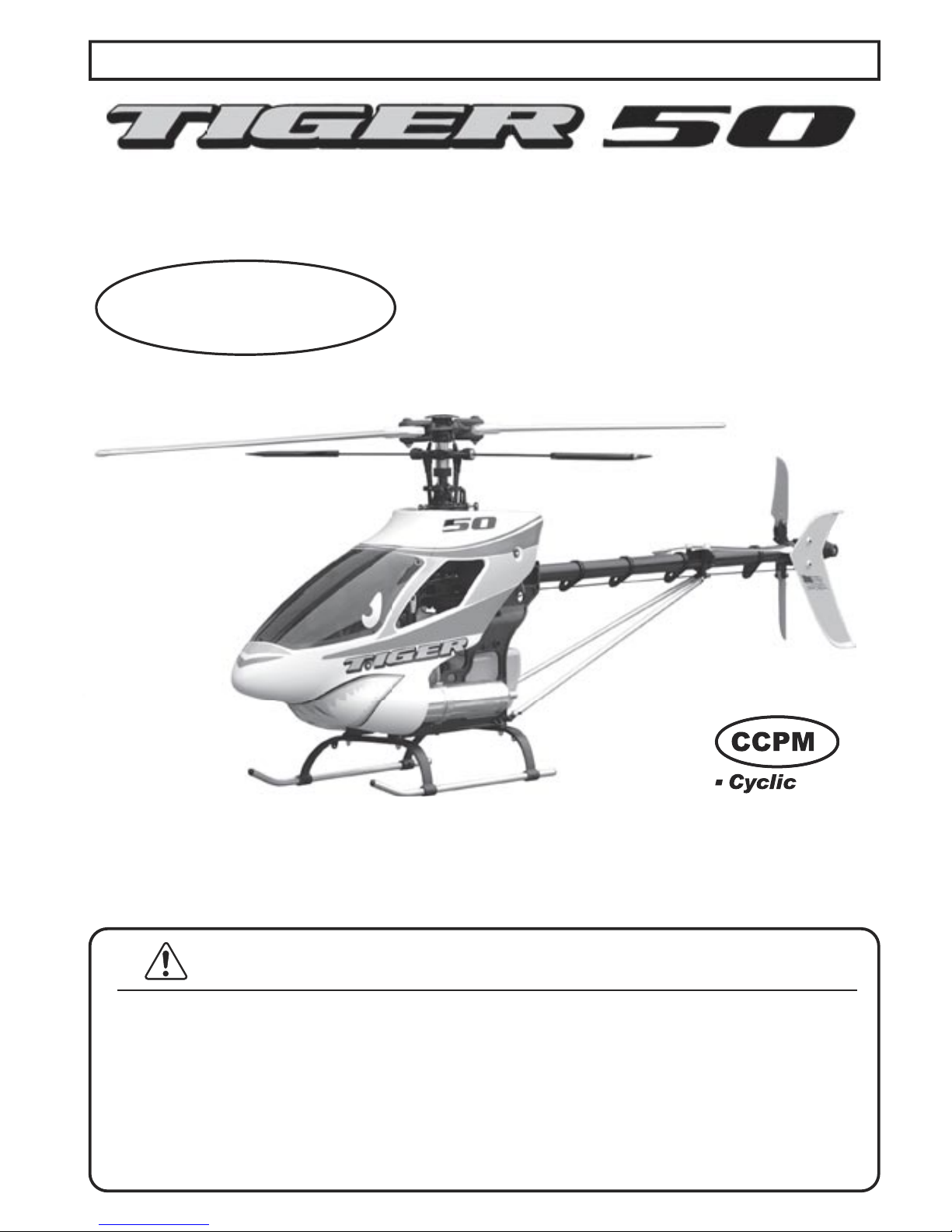
Tiger 50 Remote Control Model Helicopter - Assembly and Maintenance Manual
CCPM
Cyclic
Collective
Pitch
Mixing
.
.
.
.
PLEASE READ THIS MANUAL FULLY AND CAREFULLY!
This helicopter model is not a toy and is not suited for children.
Co
ntact with the rotating parts of this model helicopter may
cause bodily harm and/or death as well as property damage.
You,
and you alone, are responsible for the safe operation of
this remote controlled model helicopter. Audacity Models
assumes no liability for harm or damage that could occur from
the assembly and/or use/misuse of this product.
This manual
does not serve as a final and total instruction in the safe and
proper assembly and operation of remote controlled models.
Audacity Models . . . where performance exceeds expectations!
For technical updates, and
additional information visit:
www.audacitymodels.com
Entire Contents © Copyright 2004
Page 2
WARNING
INDEX
2
6
Assembly Steps
Pa
ge
Assembly Steps
Carefully follow the 8 major assembly steps in the correct sequence.
Page
You are about to embark on a wonderful adventure into the world of remote controlled (R/C)
models. However, this helicopter model is not a toy and is not suited for children. A properly
assembled and operated remote controlled model helicopter can bring many hours of enjoyment
and pleasure, but even if properly assembled and operated, the nature of an R/C system means
the radio-link between transmitter and receiver may fail, in which case even competent operators
are no longer in control. In addition, due to operator neglect or accident, worn or damaged parts
may fail causing lack of control. Contact with the rotating parts of this R/C model helicopter
may cause bodily harm and/or death as well as property damage. In addition, the overall mass
of the model in motion means contact with non-rotating parts may cause bodily harm and/or
death as well as property damage
.
You, and you alone, are responsible for the safe operation of this R/C model helicopter and
Audacity Models assumes no liability for harm or damage that could occur from the assembly
and/or use/misuse of this product. This manual does not serve as a final and total instruction
in the safe and proper assembly and operation of remote controlled model helicopters. A
lways
have personal supervision by a modeler experienced in the safe and proper handling of R/C
model helicopters
.
1.1 Clutch Bell
1.2 Tail Drive
1.3 Elevator Link
1.4 Fuel Tank
2.1 Servo-Boss
2.2 Main Frame
2.3 Avionics Platforms
3.1 Landing Gear
3.2 Main Gear & Shaft
3.3 Engine Mount & Fan
3.4 Clutch & Extension
3.5 Engine & Start Shaft
3.6 Hex Adapter / Muffler
4.1 Swashplate / Washout
4.2 Head & Flybar Arm
4.3 Flybar Installation
4.5 Rotor Control Rods
5.1 Tail Gear Box & Belt
6
7
7
8
9
10
11
12
13
13
14
14
15
16
16
17
18
4.4 Flybar Paddles
17
8.3 Canopy & Windshield
8.2 Main Blades
8.1 Blade Balance
7.2 Linkages (Starboard)
7.1 Linkages (Por
t)
6.4 Avionics Isolation
6.3 T/R Pushrod Guides
6.2 Tail Rotor Pushrod
6.1 Servo Installation
5.9 Boom Support Clam
p
5.8 Tail Boom Suppor
ts
5.7 Tail Boom Assembly
5.6 Ve
rtical Fin
5.5 Tail Rotor Grip
5.4 Tail Rotor Hu
b
5.3 Tail Pitch Leve
r
5.2 Tail Output Shaf
t
18
19
19
20
20
21
22
22
23
24
24
25
26
27
28
29
29
0.0 Preparation For Assembly
1-5
9.0 Set-up Tips
11.0 Exploded Views & Parts List
s
12.0 Accessorie
s
44-5
8
30-4
3
59-61
Page 3
3
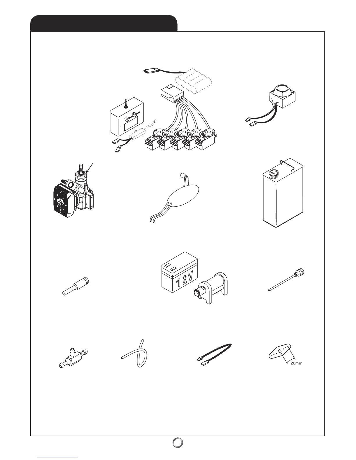
ITEMS NEED TO COMPLETE
Helicopter Fuel
(15%-30% Nitro)
6mm Hex Start Shaf
t
Cyclic/Collectiv
e
Servo Control
Horn
s
Servo Extensions
(2 each - 4”
Long)
12”
Fuel Tubing
(1/8” Silicone)
Fuel Filter
(3-way
)
1.2V Ni-Start Batter
y
12V Gell-Cell Batter
y
and Electric Starter
50-class Glo-Fuel Engine
Drive Washer Not Included
with model helicopter
Glo-Fuel Pump
6-channel - or greate
r
R/C Helicopter System
w/120
o
CCPM capabilities
Gyroscop
e
(x3)
Page 4
4
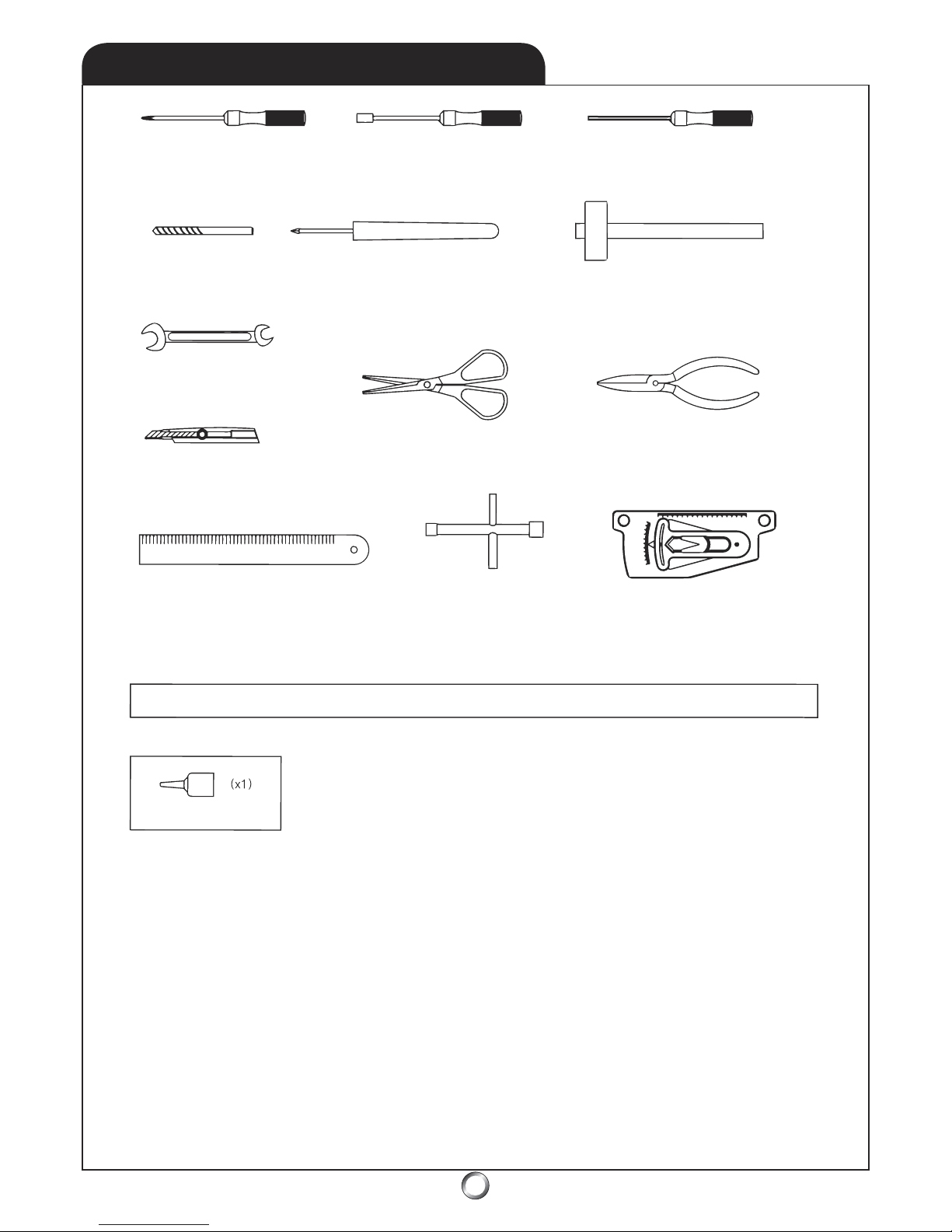
Phillips Screw Driver
Nut Drivers (4mm/5.5mm/7mm)
Allen Drivers (1.5mm/2mm/2.5mm/3mm
)
Drill Bit 1/16”
Au
ger - or - Reamer
Small Hammer
Wr
ench (5.5mm/6mm)
Le
xan Scissors
Needle-nose Pliers
Hobby Knif
e
Ruler (metric) Greater Than 30cm
4-way Wrench (8-12mm)
Pitch Gaug
e
Thread Locker Is Used To Keep Assemblies Tight As Vibration May Cause Them To Loosen
Semi-permanent
BLUE Thread Locker
Due to the vibrations caused by operation,
nuts, bolts, and set screws may have a tendency to loosen.
Repeated tightening is not the solution, instead, the careful application of thread locker is required.
Thread lock
er works something like a glue. There are various types of thread locker, from permanent
types which ar
e usually RED in color, to semi-permanent types which are usually BLUE in color. BLUE
thread locker is what is recommended. Thread locker is not needed with nylon-lock nuts, nor where
metal screws thread into plastic. Finally, be careful to remove all traces of oil or grease by applying a
degreaser or acetone to bolts prior to assembly - clean with a paper towel until all traces are gone.
NOTE: Use care when using thread locker near bearing areas as
contamination may ruin the bearing and cause it to seize.
Never use thread locker on metal to plastic
Optional Tools and Accessories:
- Dial Indicator
- Ball Link Pliers
- Piston Lo
cking Tool
- Calipers
- 10mm deep-well thin wall socket
- 2 ea. - 5/16” or 8mm 1/4” drive socket
- 2 ea. - 1/4” drive short extensions and 1/4” handles or drives
- one sheet of thin typing paper
TOOLS NEEDED FOR ASSEMBLY
Page 5
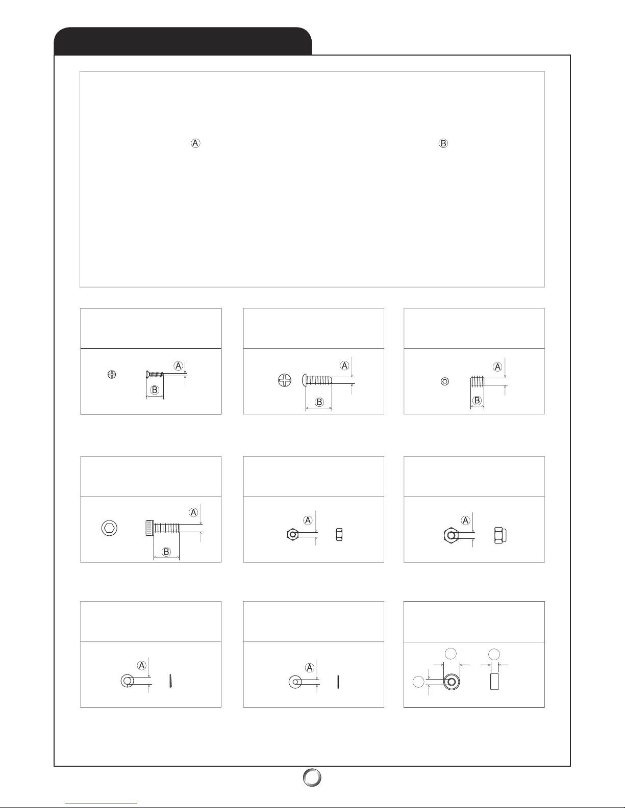
Various size nuts, bolts, set screws, and washers are used in the
Tiger 50 helicopter. Metric dimensions are given, first specifying
the diameter of the bolt or screw, then the length of the
bolt or screw. Washers and nuts are identified by the ID (inner
diameter) of the piece. Bearings are identified in order, by ID,
(inner diameter), then OD (outer diameter), then W (width).
Below are some examples of the types of hardware used.
M3mm Nylon Lock Nut
M2mm Hex Nu
t
M3x8mm Socket Head Bolt
M2x8mm Phillips Head Screw M2x8mm Self-tapping Screw
M4x4mm Set Screw
M3mm Lock Washer
M3mm Flat Washer
* NOTE: Do not use thread locker when a metal screw goes
into plastic as this may damage the plastic and cause failure.
Bearing L-1910ZZ
M10x19x7mm (ID,
OD, W )
ID
OD
W
HARDWARE IDENTIFICATION
5
Page 6
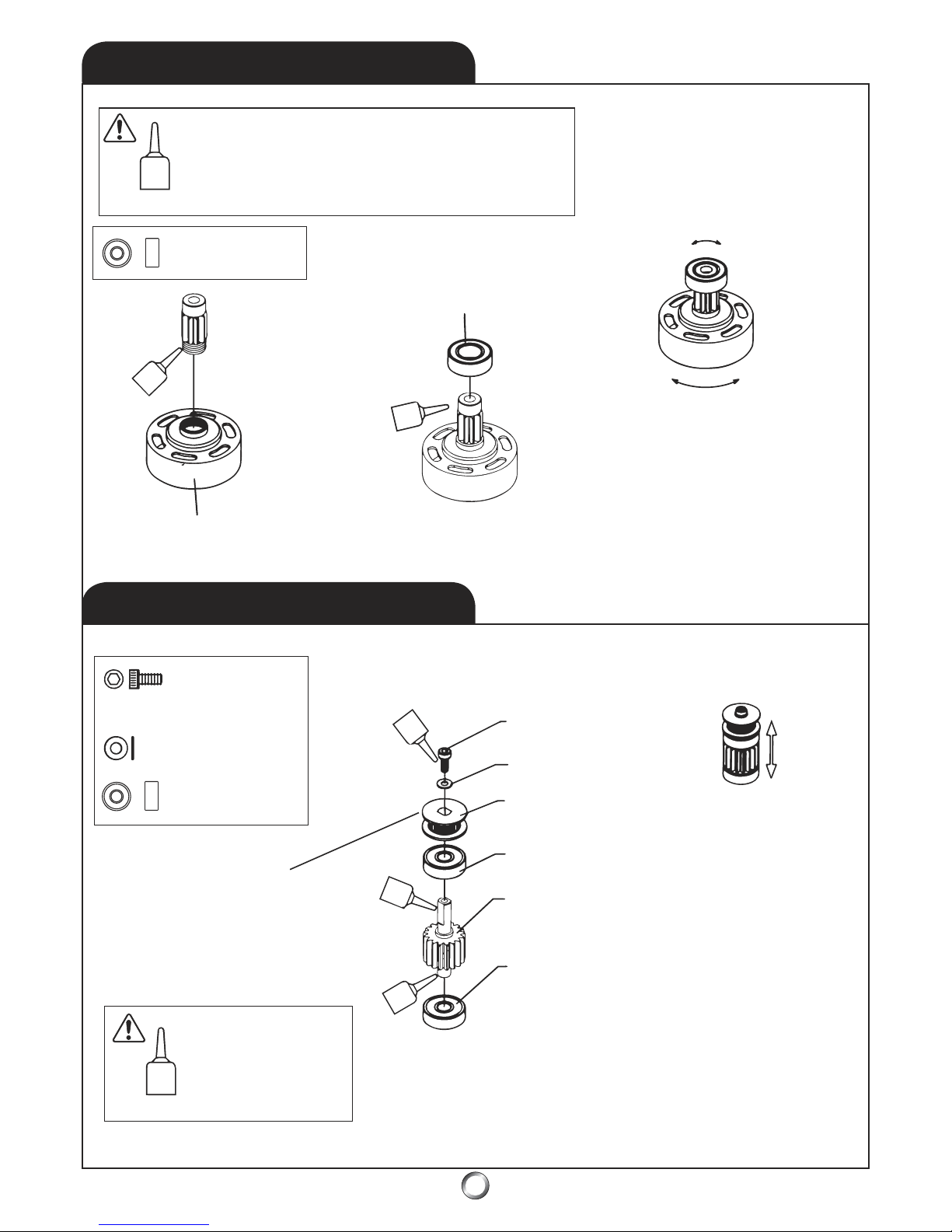
1.1
CLUTCH BELL
6
1.2
TAIL DRIVE
* NOTE: Beveled side
faces belt-side of pulley.
* NOTE: Thoroughly clean the shaft-threads and the
hole-threads of any swarf (tiny metal shavings), before
applying thread locker to ensure precise alignment
between the pinion gear and clutch bell. Use special
care to prevent thread locker from entering the bearing!
10T Pinion Gear
1 : 8.9 Ratio
Clutch Bell Assembly
Bearing L-1910ZZ
* NOTE: Use a rocking
side-to-side motion to
slip bearing onto shaft
.
* NOTE: Use a rotating
motion to twist the the clutch
bell assembly simultaneously.
M3x6mm Socket Head Bolt (x1)
M3mm Flat Washer (x1)
M3x6mm Scocket Head Bolt
M3mm Flat Wa
sher
Fr
ont Tail Belt Pulley
Bearing R-1960ZZ
Tail Driv
e
Pinion Gear
Bearing R-1960Z
Z
* NOTE: It can take several hours
for the thread locker to dr
y after
application - do not use assembly
until it’s completly set.
* NOTE: Use special
care to prev
ent thread
locker from entering
the bearings!
Bearing R-1960ZZ
M6x19x6mm (x2)
Bearing L-1910ZZ
M10x19x7mm
Page 7
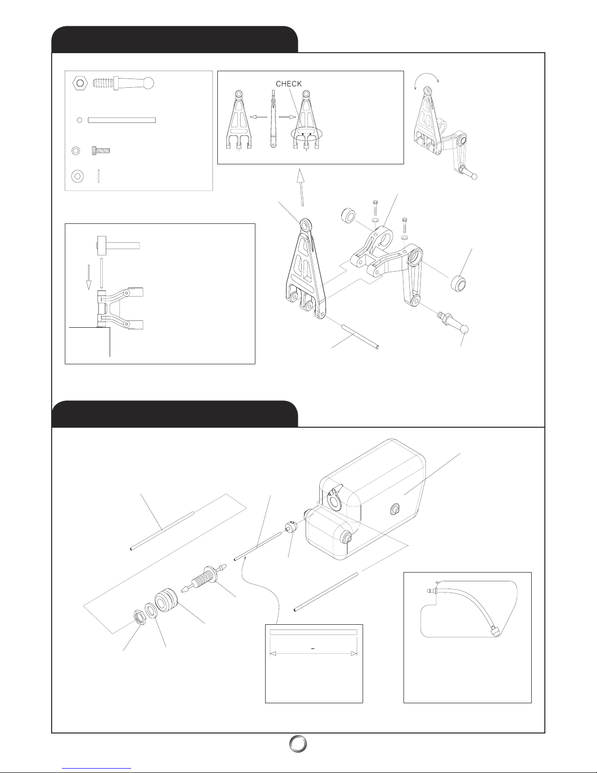
1.3
ELEVATOR LINK
7
1.4
FUEL TANK
14.5mm Long Ball Arm (x1)
Elevator Arm Pin (x1)
M2x10mm Socket
Head Bolt (x2)
M2mm Flat Washer (x2)
* NOTE
: Mold marks
must face aft - toward
the swashplate ball.
Fore Af
t
* VERIFY: swashplate
arm pivots freely on
the elevator arm.
Elevator Arm
Elevator Arm Bushing
Af
tFore
Swashplate Ar
m Link
14.5mm Long Ball Ar
m
Elevator Arm Pi
n
* NOTE: Use a small
hammer and tap gently
to drive the elevator arm
pin to join the swashplate
arm link to the elevator
arm. Ensure equal
amounts of pin protrude
on both sides of the
swashplate arm link.
Fuel Feed Line: 1/8” Silicone Fuel Tubing
(not included) - Du-Bro Medium (blue)
Silicone - No. 197 recommended.
* PRO TIP: For high nitro
use, replace the included
small diameter silicone fuel
pickup line with 1/8” ID
silicone fuel tubing.
Replace yearly!
Clunk Pickup
Muffler Pressure Line: 1/
8” Silicone
Fuel Tubing (not included)
Inspect daily - replace yearly!
Fuel Tank - 14 oz
practical capacity
* NOTE
: Ensure the clunk
swings freely by providing a
minimum 1/1
6” of clearance
from the aft fuel tank wall
.
Nu
t
Flat Washer
Rubber Tank
Gromme
t
Feed Nipple
* NOTE: Fuel pickup
line length is critical,
measure carefully!
87mm 1mm
* PRO TIP: add a small dab of silicone RTV at
the four tank mounting points when you
assemble the fuel tank into the main frames.
+
* NOTE: Check fuel
tank for swarf before
assembling it!
Page 8
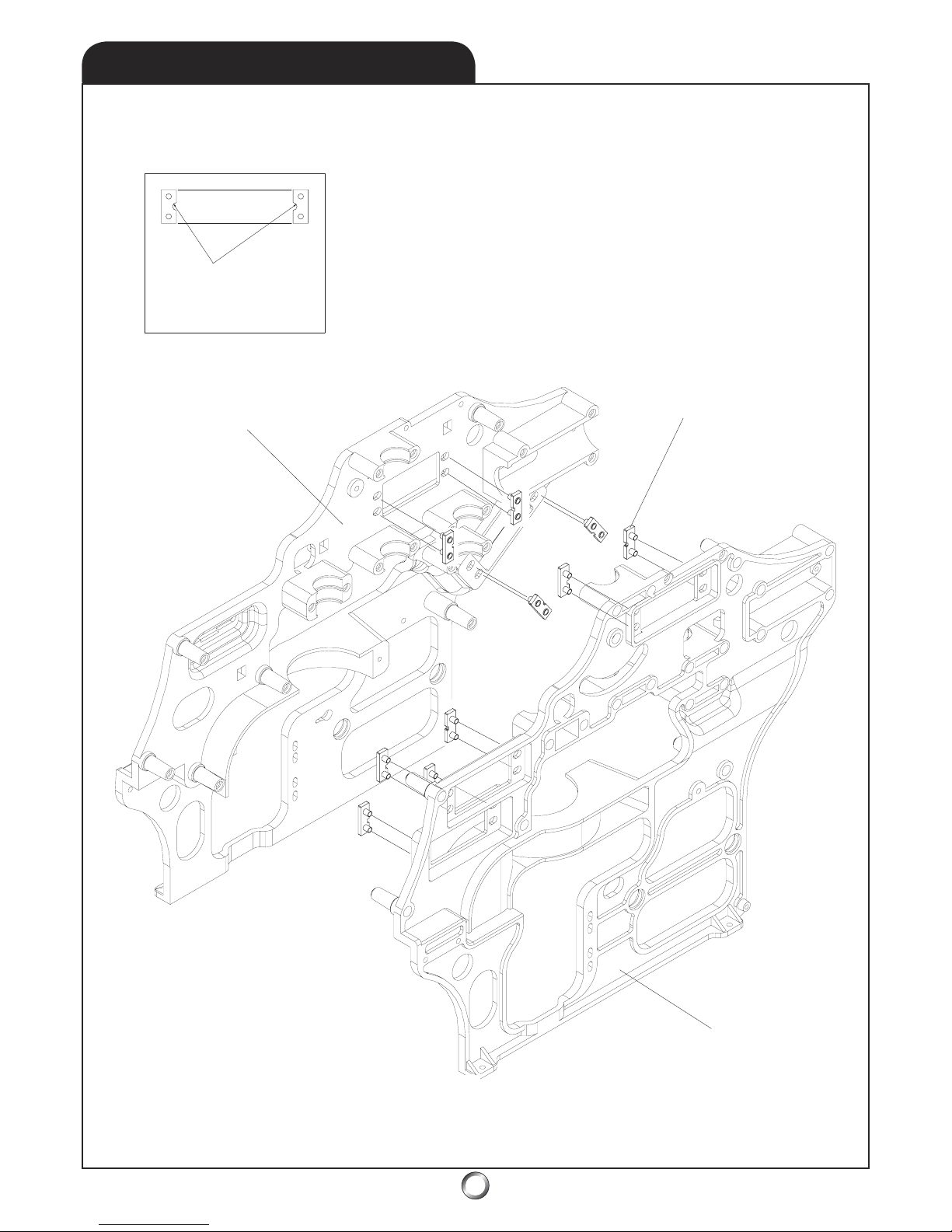
8
* NOTE: Notches
must face toward
each other!
Main Frame - Right
Main Frame - Left
Servo Mount Boss
* NOTE: Do not
glue the servo
boss
plates into place!
2.1
SERVO-BOSS
Page 9
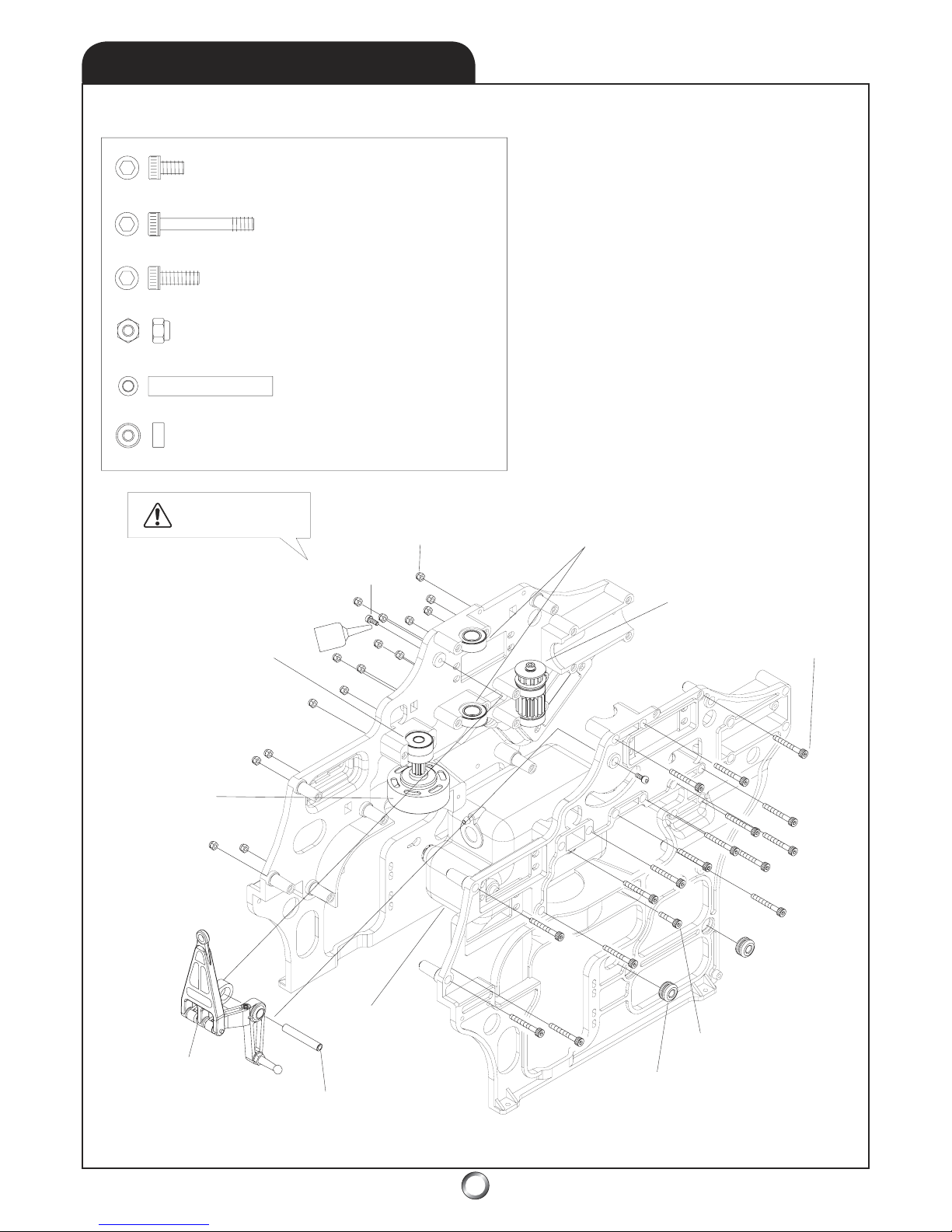
9
Elevator Arm Bushing 32mm (x1)
M3x8mm Socket Head Bolt (x2)
M3x38mm Socket Head Bolt (x16)
M3x12mm Socket Head Bolt (x1)
M3mm Nylon Lock Nut (x16)
Bearing L-1910ZZ (x2) - M10x19x7mm
Bearing L-1950ZZ (x1) - M5x19x6mm
Bearing L-1950ZZ (x1)
Bearing L-1910ZZ (x2)
M3mm Nylon Lock Nut
M3x8mm Socket Head Bolt (x2)
* NOTE: Use care
with thread locker!
Tail Drive Pinion Assembly
M3x38mm Socket
Head Bolt (x16)
(Step 1.2)
(Step 1.1)
(Step 1.3
)
(Step 1.4)
Elevator Arm
Clutch Bell Assembly
M3x12mm Socket Head Bolt (x1)
Fuel Tank Rubber Grommet (x4)
Elevator Arm Bushing 32mm (x1)
Fuel Tank Assembly
* PRO TIP: add a small dab of
silicone RTV at the f
our fuel tank
mounting points when you
assemble the fuel tank assembly
into the main frame assembly.
2.2
MAIN FRAME
Page 10
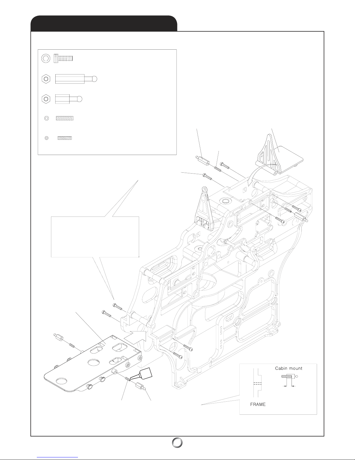
10
2.3
AVIONICS PLATFORMS
M3x10mm Socket head Bolt (x8)
Cabin Mount Stand-off 20mm (x2)
Cabin Mount Stand-off 10mm (x2)
M3x14 Set Screw (x2)
M3x12 Set Screw (x2)
Cabin Mount Stand-off
20mm (x2)
M3x14 Set
Screw (x2
)
Gyroscope
Platform
M3x10mm Socket head Bolt (x8)
* NOTE: Don’t use
thread locker on
plastic parts!
Radio Platform
Cabin Mount Stand-off
10mm (x2)
M3x12 Set Screw (x2)
Use thread locker on
set screw, install it
evenly into standoff
and let it dry before
assembly to frame
.
Page 11
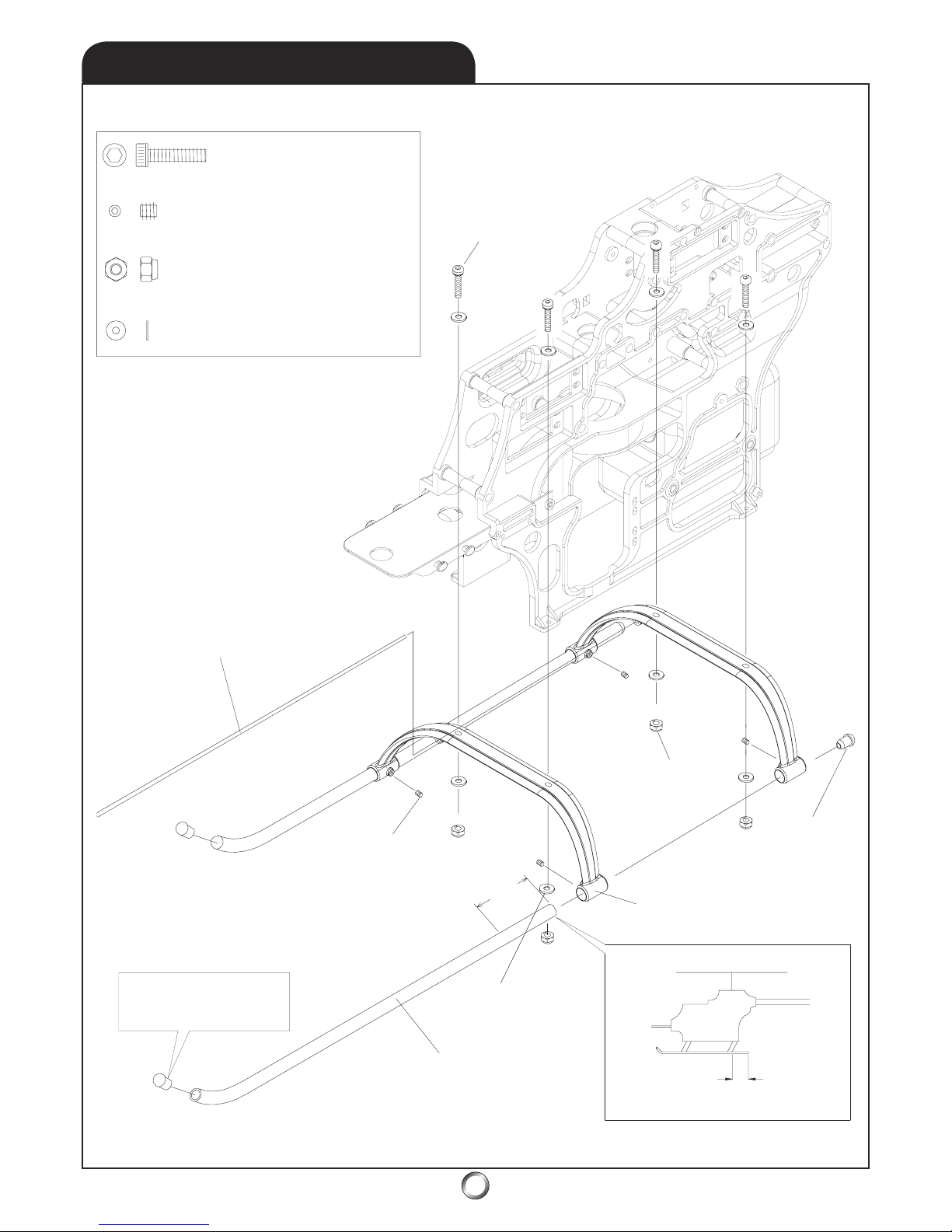
11
M3x15mm Socket
Head Bolt (x4)
M3x6mm Set Screw (x4)
M3mm Nylon Lock Nut (x4)
M3mm Flat Washer (x8)
Antenna Guide Tube
M3mm Nylon
Lock Nut (x4)
M3x15mm Socket Head Bolt (x4)
M3x6mm Set
Screw (x4)
Skid Cap (x4)
Landing Skid (x2)
Landing Gear Strut (x2)
Fore
Af
t
* NOTE: Minimum length = 1-3/16”
* NOTE: Use a small dab
of silicone RTV as glue to
help retain sk
id caps.
* PRO TIP: Use nylon zip-ties
instead of socket head bolts
and nylon lock nuts to secure
landing gear struts to the main
frame - this helps prevent
greater damage in case you
slam dunk your helicopter
when practicing 3D.
M3mm Flat Washer (x8)
1-3/1
6
”
3.1
LANDING GEAR
Page 12
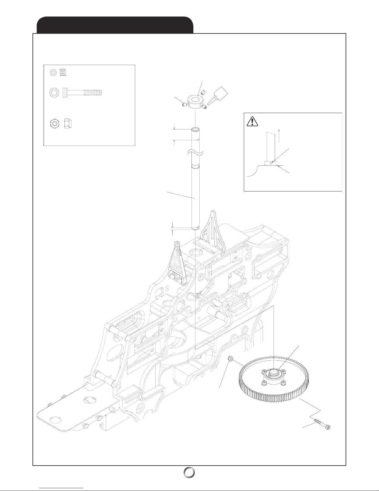
12
M4x4mm Set Screw (x3)
M3mm Nylon Lock Nut (x1)
Mast Stoppe
r
M4x4mm Set
Screw (x3)
Long
Shor
t
Main Mast
Evenly tighten the
M4x4 set screws in
the mast stopper (use
thread locker)
.
The beveled edge of
the mast stopper
faces the bearing
.
Gently draw up the
main mast to remove
the slack.
NOTE
Autorotation Clutch
Nylon Lo
ck
Nut (x1)
M3x22 Socket Head
Shoulder Bolt (x1)
M3x22 Socket Head Shoulder Bolt (x1)
* PRO TIP: The 89T - Main Gear
(has 89-teeth) and when meshed
with the 10T - Pinion Gear results
in a 8.9:1 final drive ratio
.
3.2
MAIN GEAR & SHAFT
Page 13
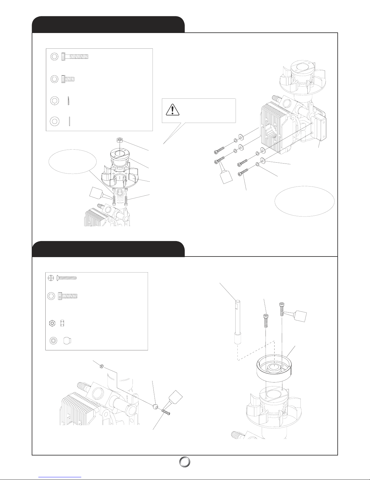
3.3
ENGINE MOUNT & FAN
M3x15mm Socket
Head Bolts (x4)
M3mm Flat Washer (x4)
M3mm Lock Washer (x4)
M3x8mm Socket
Head Bolts (x4)
* NOTE: Do not use
thread locker on the
crankshaft engine nut.
Crankshaft
Engine Nut
Clutch Hub
Co
oling Fan
M3x8mm Socket
Head Bolt (x4)
Not all engines will
include a prop-drive
yet it is required.
46-50 class engine
is not supplied in
#22501 or #22502
Engine Moun
t
M3x15mm Socket
Head Bolts (x4)
M3mm Lock Washer (x4)
M3mm Flat
Washer (x4)
M2x8mm Phillips Head Screw (x1)
Start Shaf
t
M3x8mm Socket
Head Bolt )x2)
M2mm Hex Nut (x1)
Stainless Steel
Ball Joint (x1)
Stainless Steel Ball Joint (x1)
M2mm Hex Nut (x1)
M2x8mm Phillips Head Screw (x1)
M3x8mm Socket
Head Bolt (x2
)
Clutch
Assembly
* PRO TIP: Use a dial indicator
to check for excessive runout.
Beware false readings by
measuring at the shoes. Take
measurements at the hub. Try
both rotating the assembly
180o or just loosening and
tightening bolts as just that
may make a difference.
* PRO TIP: Using a marker, place a dot on the
clutch hub - then use a dial indicator to check
for excessive runout. Time spend here may
pay off in a smoother running helicopter.
Simply loosening and rotating the assembly
as little as a 1/8 turn can make a difference
.
* PRO TIP: If a commercial piston-locking tool isn’t
av
ailable, a plastic handle from a toothbrush - used to
block the piston - can aid in tightening the engine nut.
Further details at:
www.audacitymodels.com
* PRO TIP:
A 1/4” drive
10mm
deep well
thin wall
socket is
perf
ect for
engine nut.
13
3.4
CLUTCH & EXTENSION
Page 14
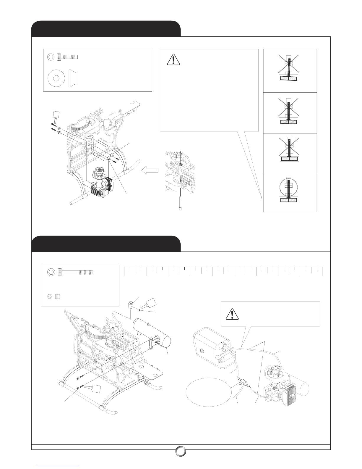
3.5
ENGINE & START SHAFT
3.6
HEX ADAPTER/MUFFLER
14
M3x30mm Socket Head Bolt (x2)
M4x4mm Set Screw (x1)
Hex Start Adapter
M4x4mm Set Screw (x1)
Muffler (option)
M3x30mm Socket
Head Bolt (x2)
* NOTE: Slide muffler mounting bolts into engine
crankcase before mounting engine to the main frame.
1/8” Silicone Fuel
Tubing (option)
* NOTE: Installation of
a fuel filter is highly
recommended (option)
* VERIFY: Muffler pressure and fuel
feed 1/
8” silicone rubber tubing is a
maintenance item. Inspect daily
.
* NOTE:
Tighten set screw
against start shaf
t’s flat.
3-1/2”
4-1/2
”
1-1/2”
4”
0 431 2
M3x12mm Socket Head Bolt (x4)
M3mm Cap Bolt Holder (x4)
M3mm Cap Bolt Holder (x4)
M3x12mm Socket
Head Bolt (x4)
Start Shaf
t
Angled - INCORREC
T
Too Low - INCORRECT
Too High - INCORRECT
CORRECT
There is a slight amount of adjustment for
the engine mount to fit within the main
frames. This adjustment is for the purpose
of aligning the clutch. The clutch MUST fit
squarely within the clutch bell to ensure
proper engagement of the clutch shoes
against the friction material. Use care
when fitting to align as well as possible
.
* PRO TIP: Use a thin strip of typing paper
wrapped once around clutch for alighnment.
VERIFY
* PRO TIP: Lightly
snug engine mount
bolts, align clutch,
then tighten bolts.
Page 15
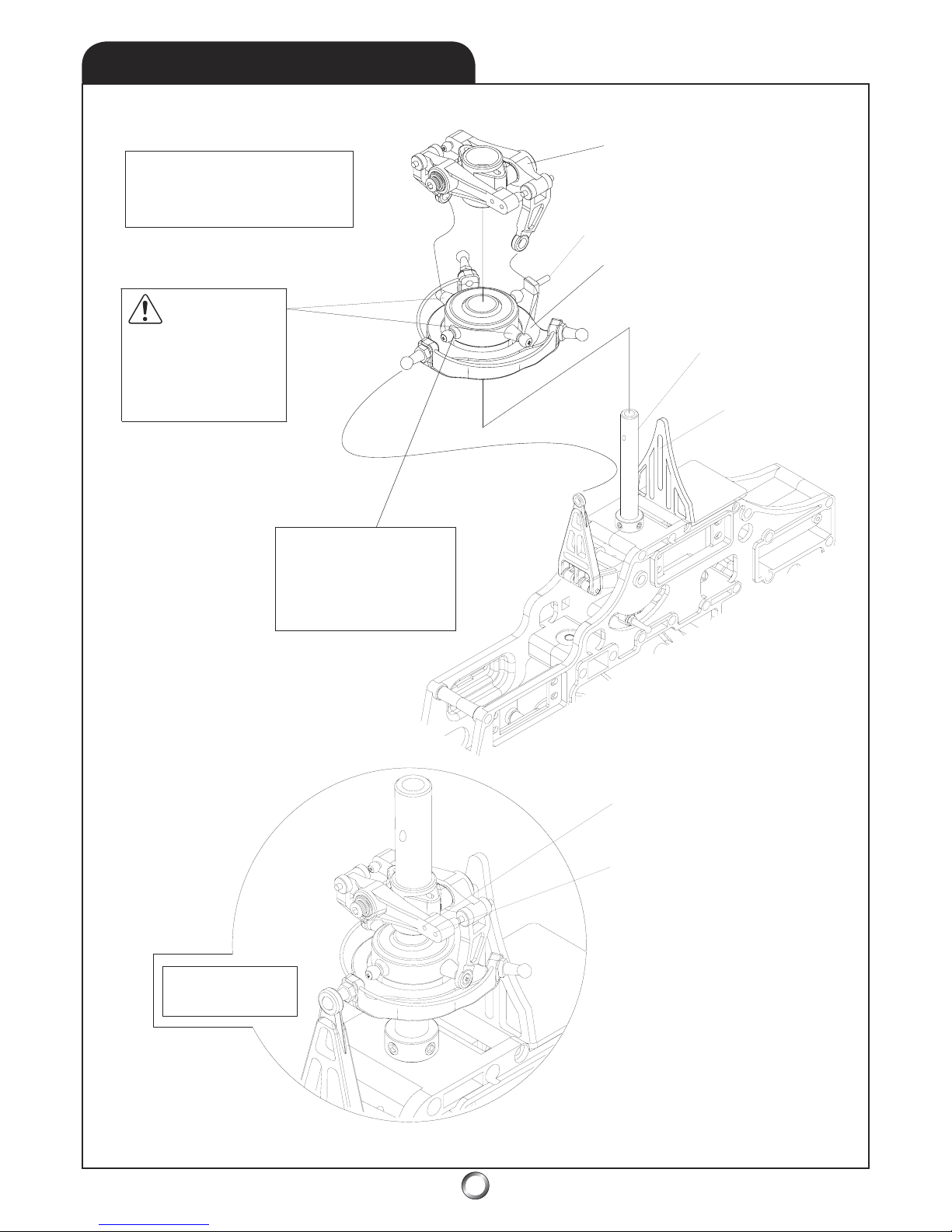
15
Complete Assembly
VERIFY
The washout links must
connect to the two
longer-stud balls on the
swashplate inner ring
.
* PRO TIP: Lubricate the washout
slider with a few drops of light
machine oil such as 3-in-1 daily.
Washout Assembly
120o Swashplate Assembly
Guide Pin
Slot for guide pi
n
Hollow Main Shaf
t
(lighter & stronger
than solid shaf
t)
Greater Stability - inner holes
of washout mixing arms
.
Greater Ag
ility - outer holes
of washout mixing arms
.
4.1
SWASHPLATE/WASHOUT
* PRO TIP: For extreme
performance, or 3D flight,
extend both of the short
inner balls to match the
length of the longer balls.
Page 16
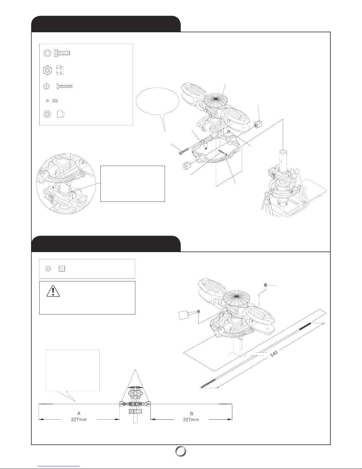
4.2
HEAD & FLYBAR ARM
4.3
FLYBAR INSTALLATION
16
M3x20mm Socket Head
Shoulder Bolt (x1)
M3mm Nylon Lock Nut (x1)
M2x10mm Phillips
Head Screw (x2)
Stainless Steel Ball (x2)
M3x5mm Set Screw (x2)
Rotor Head Assembly
Fly Bar
Stopper
M3mm Nylon
Lock Nut (x1)
M3x20mm Socket Head
Shoulder Bolt (x1)
* PRO TIP: This
shoulder bolt is
also known as a
Jesus bolt.
M3x5mm Set
Screw (x2
)
M2x10mm Phillips
Head Screw (x2)
Stainless Steel
Ball (x2)
* NOTE: Ensure the rotor
hub pin engages the
washout base groove
before securing the rotor
head onto the main shaft.
M4x6mm Set Screw (x2)
Center the flybar in the flybar control arms
.
VERIFY
M4x6mm Set
Screw (x2
)
* NOTE: Adjust
so that both A&B
sides are exactly
the same length.
Page 17
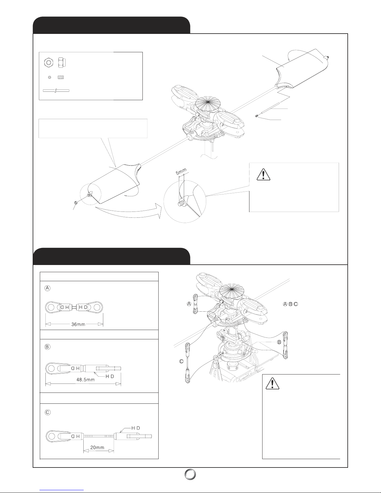
4.4
FLYBAR PADDLES
ROTOR CONTROL RODS
4.5
17
ROTOR CONTROL RODS
M3mm Nylon Locking Nut (x2)
M4x6mm Set Screw (2)
3x70mm weight (x2)
* NOTE: Flybar paddles - short leading
edge section forward - clockwise rotation.
Flybar Paddle
3x70mm weight (x2)
M4x6mm Set Screw (2)
M3mm Nylon
Lo
cking Nut (x2)
Thread each flybar paddle onto
flybar until 5mm of threaded rod
protrudes beyond the end
.
VERIFY
* PRO TIP: For greater agility,
don’t install the weight inside
the flybar paddles
.
* NOTE
: Both flybar paddles plus the
flybar control arm should (all three) be
perfectly parallel to each other
.
A - Seesaw Arm to Main Blade Grip
M2.3x13mm Threaded Rod (x2)
SHORT - HD Ball Link Ends (x2)
B - Washout Arm to Flybar Control
M2.3x13mm Threaded Rod (x2)
LONG - HD Ball Link Ends (x2)
C - Swashplate to Seesaw Arm
M2.3x40mm Threaded Rod (x2)
LONG - HD Ball Link Ends (x2)
- Assemble three
pairs of pushrods.
WARNING
The HD Ball Link Ends
are designed to fit one
way only.
Snap the
HD link ov
er the ball
with the HD facing
outward - away
from
the ball.
Page 18
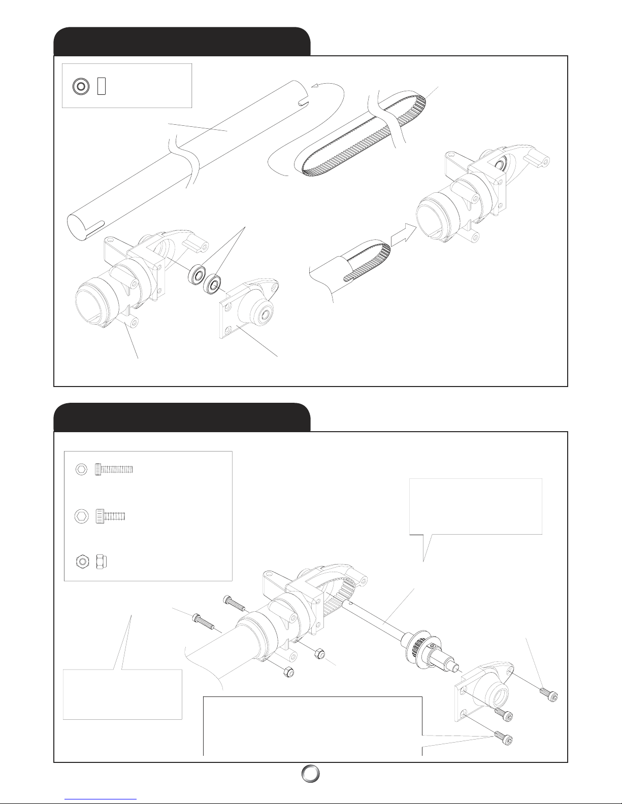
5.2
TAIL OUTPUT SHAFT
5.1
TAIL GEAR BOX & BELT
Tail Boom (L=690mm)
Shor
t
Slot
Long
Slot
Tail Output Shaft Bearing
L-1350ZZ (x2) 5x13x4mm
Tail Gear Case (L)
Tail Gear Case (R)
Tail Drive Belt
S3M-1596
M2.6x12mm Socket Head Bolt (x2)
M3x8mm Socket Head Bolt (x3)
M2.6mm Nylon Lock Nut (x2)
M2.6x12mm Socket Head Bolt (x2)
M2.6mm Nylon
Lock Nut (x2)
M3x8mm Socket
Head Bolt (x3)
Tail Output Shaft Assembly
* NOTE
: Ensure the bearing is
in place, then slip the tail
output shaft assembly through
the tail drive belt and seat it
.
* NOTE: Seat the tail gear
case fully onto the tail boom
before snugging the bolts.
Bearing L-1350ZZ
M5x13x4mm (x2)
* PRO TIP: Use care when tightening the bolts into the
tail gear case - as soon as the head contacts the case half,
that’s it. It’s easy to overtighten and strip the threads. A
temporary repair is to use a drop of medium CA in the
hole then re-install the screw.
18
Page 19
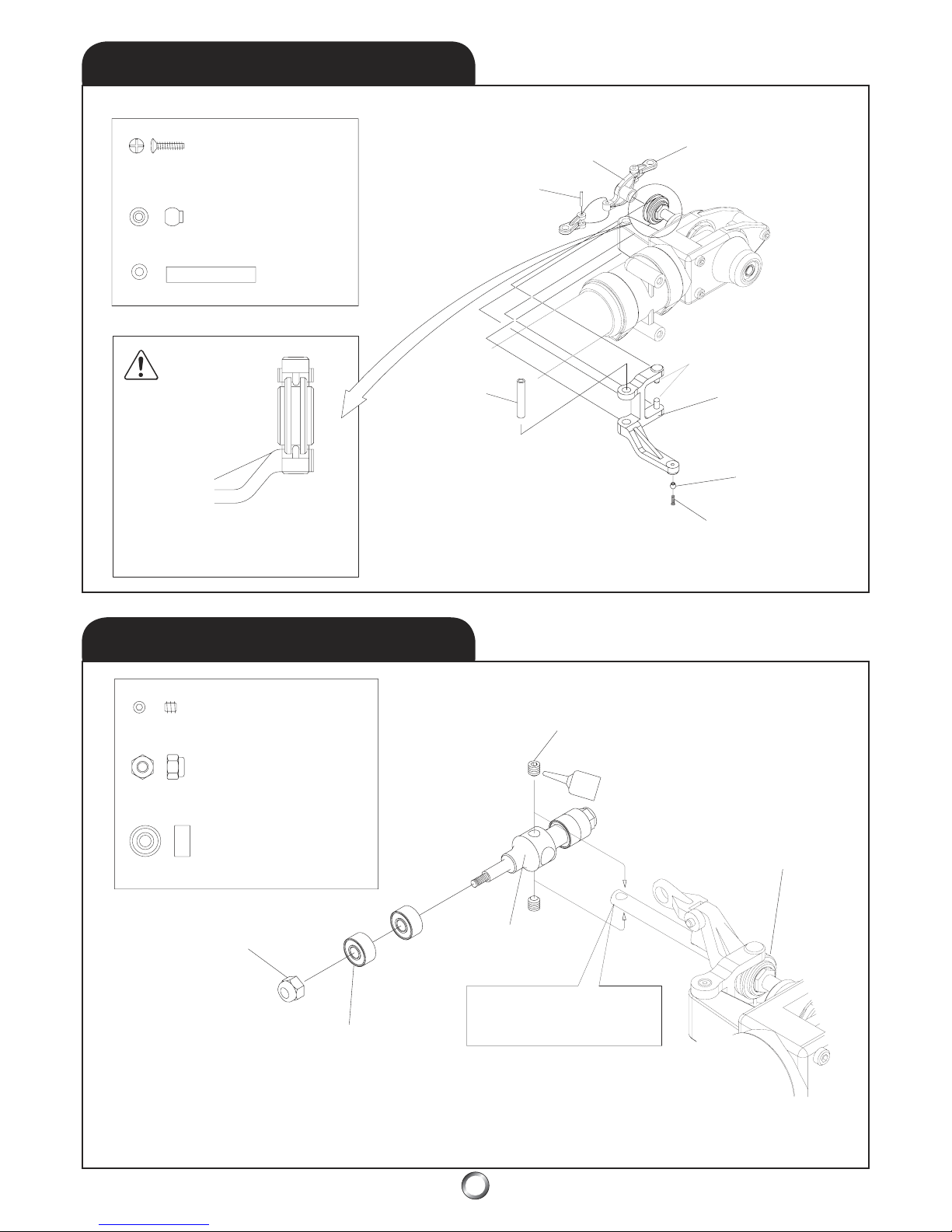
5.4
TAIL ROTOR HUB
5.3
TAIL PITCH LEVER
Stainless Steel Ball (x1)
Tail Lever
Bushing (x1)
Tail Pitch Plat
e
Tail Pitch Link Pin
Tail Pitch Link
Tail Lever
Bushing (x1)
Tail Pitch
Control Leve
r
Stainless Steel
Ball (x1)
M2x8mm Phillips Head Screw (x1
)
VERIFY
* NOTE: Ensure tail pitch control lever
pins fully engage the slot in the tail
slide ring assembly.
M4x4mm Set Screw (x2)
M3mm Nylon Lock Nut (x2)
Bearing, R840ZZ
M4x8x4mm (x4)
M4x4mm Set Screw (x2)
Tail Slide Ring Assembly
Tail Rotor Center Hub
Bearing, R840ZZ (x4)
M3mm Nylon
Lo
ck Nut (x2)
* NOTE
: Ensure the set screws
seat fully within the holes at the
end of the tail output shaf
t.
M2x8mm Phillips Head Screw (x1)
Pins
19
Page 20
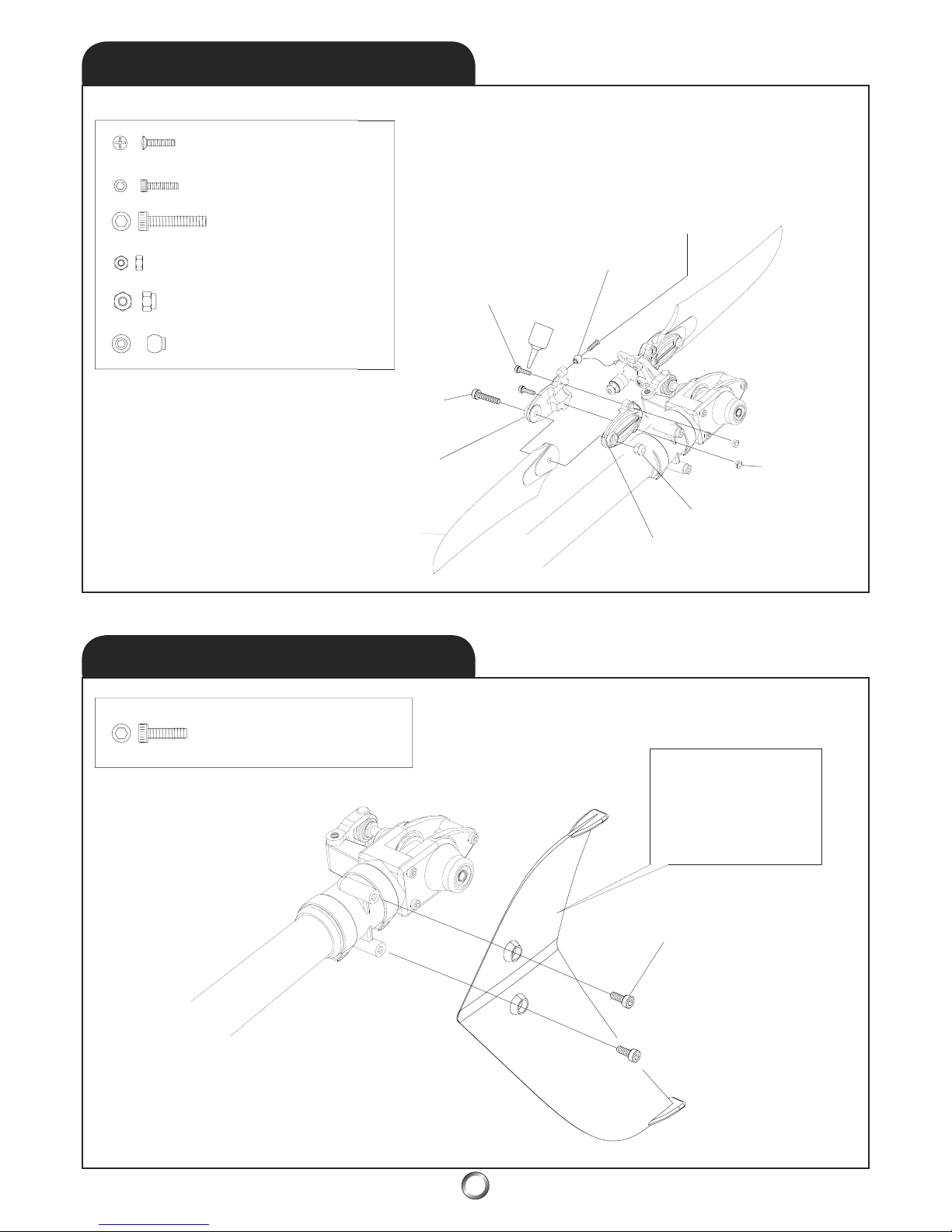
5.6
VERTICAL FIN
5.5
TAIL ROTOR GRIP
M2x8mm Phillips Head Screw (x2)
M2x8mm Phillips
Head Screw (x2)
M2x8mm Socket Head Bolt (x4)
M3x15mm Socket Head Bolt (x2)
M2mm Hex Nut (x4)
M3mm Nylon Lock Nut (x2)
Stainless Steel Ball (x2)
Stainless Steel
Ball (x2)
M2x8mm Socket
Head Bolt (x4)
M2mm Hex
Nut (x4)
M3mm Nylon Lock Nut (x2)
Tail Rotor
Grip -
B
Tail Rotor
Grip - A
M3x15mm Socket Head Bolt (x2)
Tail Rotor Blade
M3x10mm Socket Head Bolt (x2)
* NOTE
: Use care to not
overtighten the socket
head bolts as they may
crack the vertical fin or
strip out the threads in
the tail gear case
.
M3x10mm Socket Head Bolt (x2)
* PRO TIP: Snug the tail rotor blade bolts,
but don’t tighten so much the blades
don’t swing freely under their own weight.
20
Page 21
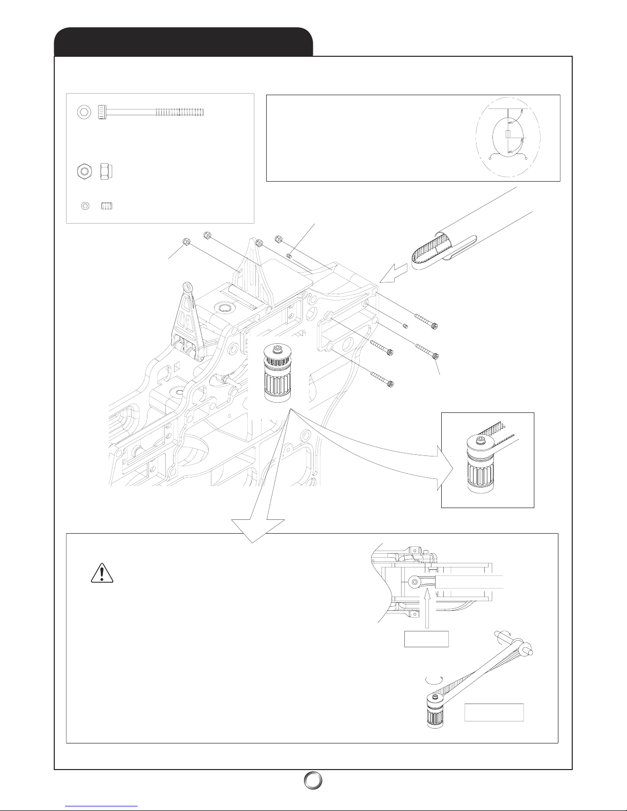
5.7
TAIL BOOM ASSEMBLY
M3x38mm Socket Head Bolt (x4)
M3mm Nylon Lock Nut (x4)
M3x4mm Set Screw (x2)
* NOTE: Ensure the orientation and the tension
of the tail drive belt are correc
t. Verify the tail
rotor output shaft is perpendicular to the main
shaft by sighting from behind. Then set the
tension in the belt as noted below and tighten
both the bolts in the main frame plus the set
screws securely against the tail boom
.
M3x4mm Set Screw (x2)
M3mm Nylon Lock Nut (x4)
M3x38mm Socket Head Bolt (x4
)
VERIFY
TENSION: Ensure there is a little slack in the tail rotor
drive belt. Reach in with your fingertip, or with the tip
of a screwdriver, and push one side against the other.
They should almost touch without great effort.
TENSION
ORIENTATION: The tail drive belt must be oriented
correc
tly to ensure the proper rotation of the tail rotor
output shaft. There is a 90o clockwise twist when
viewed from the front of the tail boom assembly.
ORIENTATION
90
o
90
o
21
Page 22
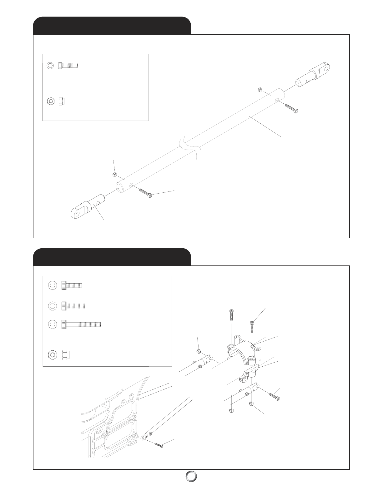
5.8
TAIL BOOM SUPPORTS
5.9
BOOM SUPPORT CLAMP
M2.6x10mm Socket Head Bolt (x4)
M2.6mm Nylon
Lo
ck Nut (x4)
M2.6mm Nylon Lock Nut (x4)
M2.6x10mm Socket Head Bolt (x4)
Tail Boom Support End (x4)
Tail Boom Support (x2
)
M3x10mm Socket Head Bolt (x2)
M3x12mm Socket Head Bolt (x2)
M3x22mm Socket Head Bolt (x1)
M3mm Nylon Lock Nut (x3)
M3x10mm Socket Head Bolt (x2
)
M3mm Nylon
Lock Nut (x3)
M3x22mm Socket
Head Bolt (x1)
Tail Boom Suppor
t
Clamp (Upper)
Tail Boom Suppor
t
Clamp (Lower)
M3x12mm Socket Head Bolt (x2
)
M3mm Nylon
Lock Nut (x3)
22
Page 23
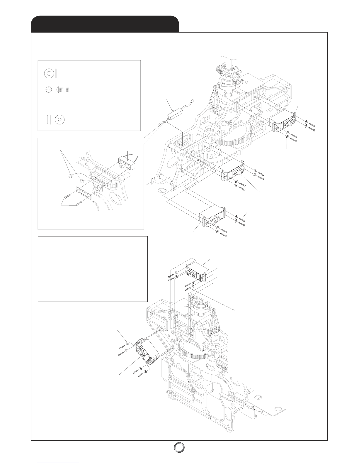
6.1
SERVO INSTALLATION
M2.6mm Flat Washer (x12)
M2.6x10mm Self Tapping Screw (x12)
Round Rubber Grommet (x2)
Round Rubber Grommet (x2)
Receiv
er
Switch
Switch Plate & Screw
s
* NOTE: Do not overtighten screws.
Receiv
er
Switch
M2.6mm Flat Washer (x12)
Throttle Serv
o
Swash Left
Serv
o
Swash Front Serv
o
M2.6x10mm Self
Tapping Screw (x12)
Swash Right Serv
o
M2.6x10mm Self Tapping Screw (x12)
M2.6mm Flat Washer (x12)
Rudder Serv
o
* PRO TIP:
Due to the sharing of the flight loads
between the three swashplate servos used by an
eCCPM system, the individual servos do not have
to be tremendously strong.
The Tiger 50 has
been ex
tensively flown with standard 40-oz ball
bearing servos - with excellent results. However,
ex
treme performance pilots will notice a nice
improv
ement when upgrading to digital servos.
In order of importance, upgrade to digital on the
tail rotor first, then the swashplate serv
os.
* PRO TIP:
Do not overcompress
the servo’s rubber grommets. They
serve as vibration isolators. Also,
make sure to use the brass eyelets
(inserted from the bottom) to fix
the compressed grommet height
.
23
Page 24
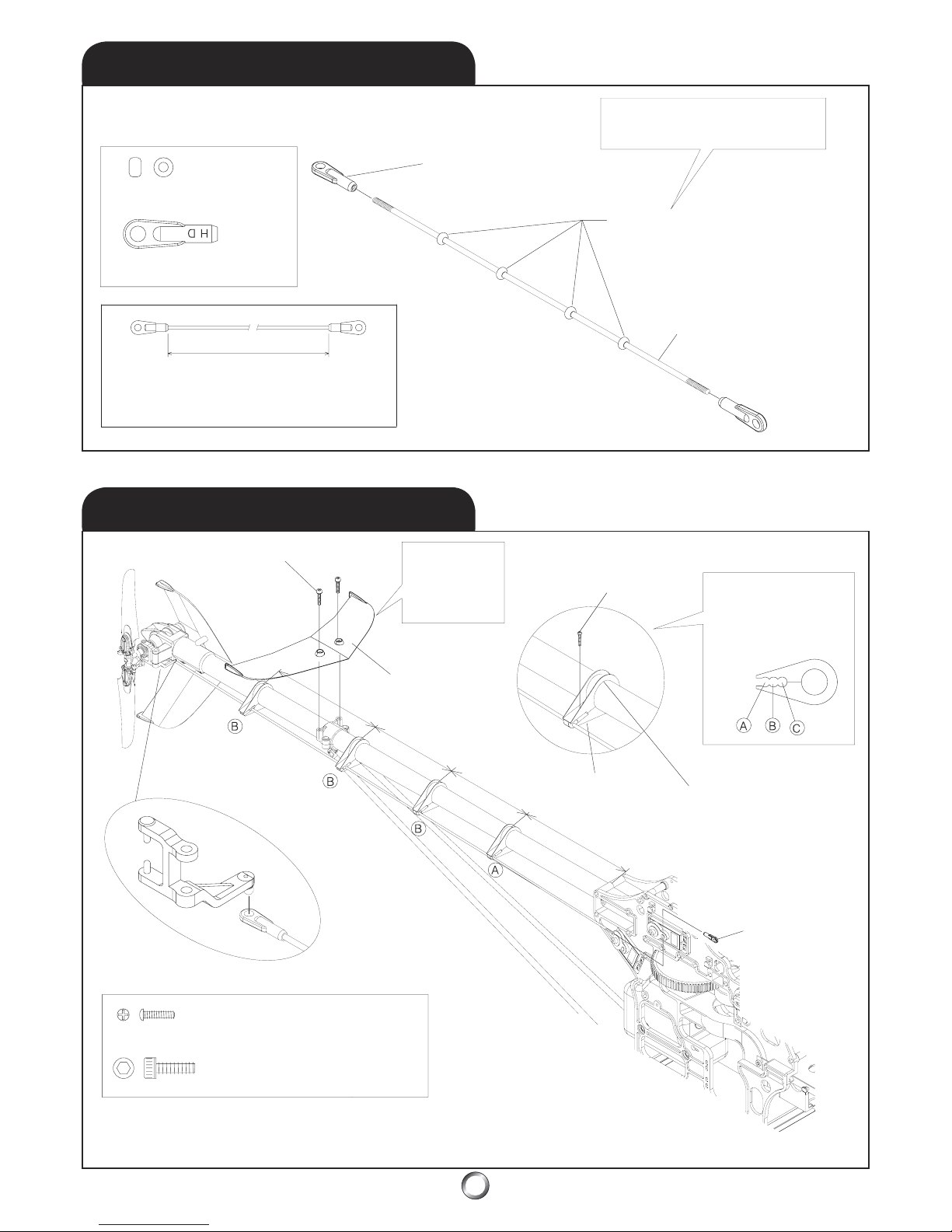
6.3
T/R PUSHROD GUIDES
6.2
TAIL ROTOR PUSHROD
T/R Pushrod Bushings (x4)
LONG - HD Ball Link Ends (x2)
675mm
Length when servo arm and tail rotor control arm
are set perpendicular to the tail boom - neutral.
* NOTE: Slip pushrod bushings onto
pushrod before the second ball link.
T/R pushrod = 675m
m
between the link ends
M3x10mm Socket Head Bolt (x2)
M3x10mm Socket Head Bolt (x2)
* NOTE: Set
horizontal fin
perpendicular
to main shaf
t.
Horizontal Fin
T/R (tailrotor)
Pushro
d
LONG - HD Ball Link Ends (x2)
M2x8mm Self Tapping Screw (x3)
M2x8mm Self Tapping
Screw (x4)
* NOTE: The goal is to
use the 3-positions of
adjustment to create
the most free path.
LONG - HD Ball
Link Ends (x2)
T/R Pushrod Guide
110mm
110mm
130mm
130mm
* PRO TIP: Upgrade the
pushrod and guides to
an aftermarket one-piece
carbon fiber pushrod
without guides.
* PRO TIP:
After you
complete adjustment, add a
drop of thin CA at the top of
each guide to “spot weld” it
to the boom. It’s easy to later
break the guide free
.
24
Page 25
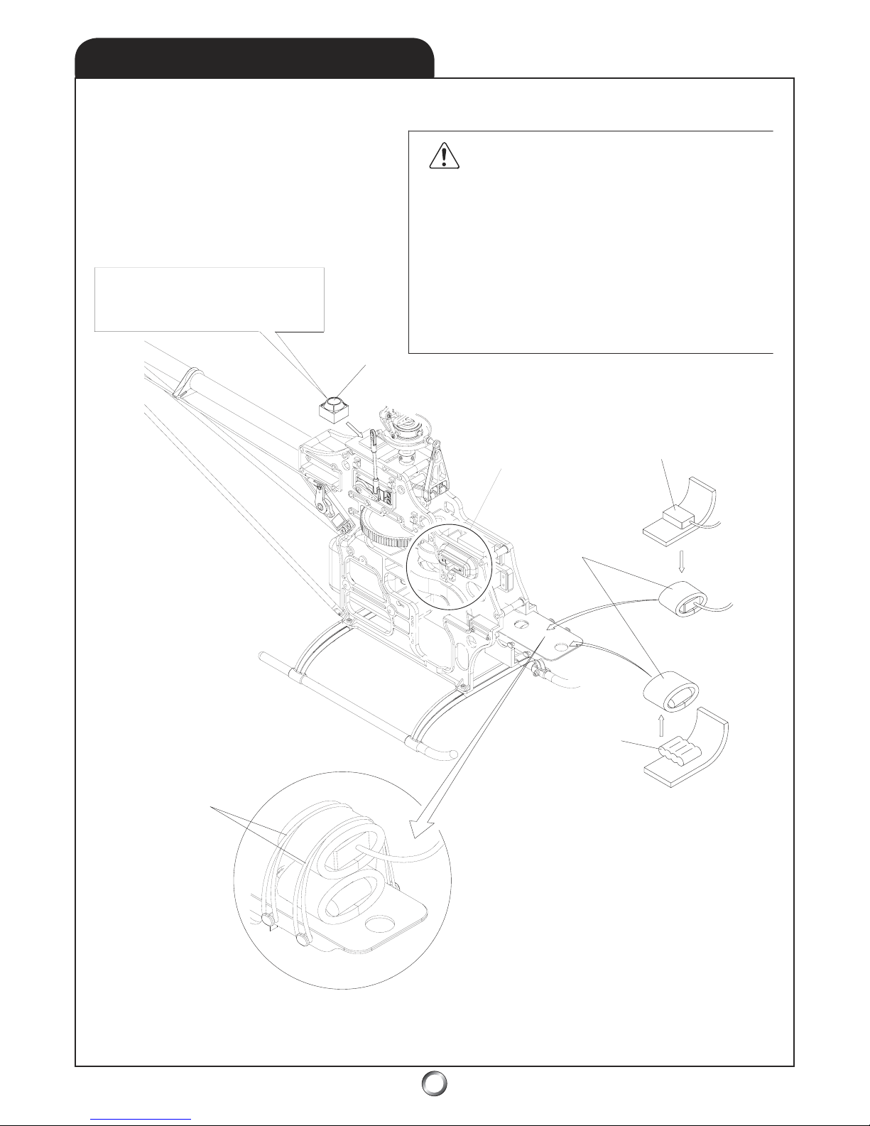
6.4
AVIONICS ISOLATION
Gyroscope
Receiver
Foam Rubber
(not included
)
4.8V 4-cell
Battery P
ack
6.0V 5-cell
* PRO TIP: Use #64
rubber bands to secure
avionics package. These
are a maintenance item
and should be checked
during the preflight.
* NOTE
: Use rubber
grommets to isolate the
receiver switch from
vibration induced failure.
* PRO TIP
: Use a 4-cell battery pack for most uses.
Extreme performance pilots seeking the ultimate in
servo speed may wish to use either a 5-cell battery pack,
or even a 6-cell regulated (to 6.0V) battery pack.
However, it’s important to realize that a 5-cell 1000mAh
pack will not last as long as a 4-cell 1000mAh pack due
to the higher drain caused by running the ser
vos on
higher voltage. The prudent pilot will check batteries
before each and every flight with a battery checker
which, places a simulated load on the battery pack.
CAUTION
The importance of protecting the avionics package (receiver,
gyro amplifier,
governor, and battery pack) from the primary
vibrations caused by the engine and the secondary vibrations
induced by the main and tail rotors cannot be overemphasized.
These forces may lead to premature failure of the avionics
components leading to intermittent or permanent loss of control
and possibly property damage, injury, or even death. Use a high
quality wrap such as Du-Bro No. 514 - 1/2
” (12.7mm) thick foam
rubber. Do not use plastic bubble-wrap, open-cell foam, or servo
tape for mounting these delicate components
.
* PRO TIP: The gyroscope platform should
be cleaned by lightly wiping down with
acetone before using the mounting tape
supplied by the gyroscope manufacturer.
25
Page 26
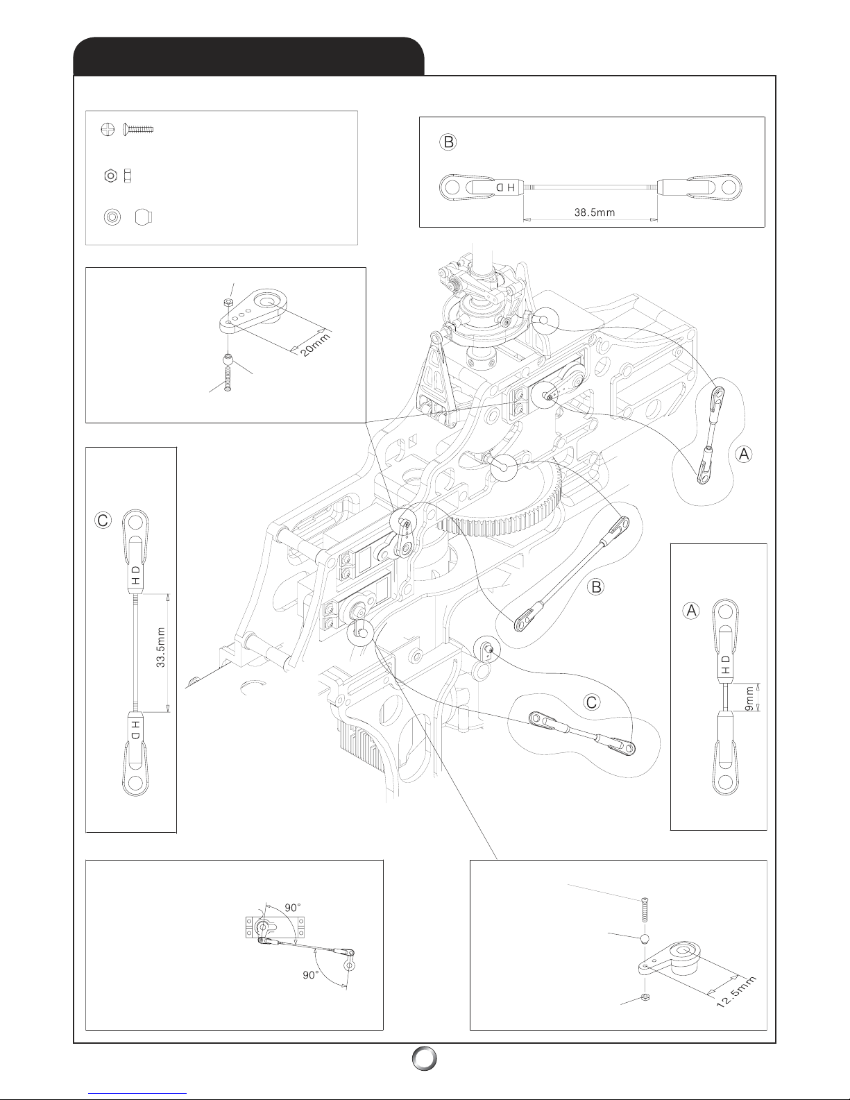
7.1
LINKAGES (PORT)
M2x8mm Phillips Head Screw (x3)
Stainless Steel Ball (x3)
M2 Hex Nut (x3)
THROTTL
E
Ball at 12.5mm
2.3x30mm
Threaded Rod
M2x8mm Phillips
Head Scre
w
Stainless Steel Ball
Stainless Steel Ball (x3)
M2x8mm Phillips Head Screw (x3)
M2 Hex Nut (x3)
M2 Hex Nut
SWASHPLATE
Ball at 20mm
2.3x50mm
Threaded Rod
2.3x50mm Threaded Ro
d
THROTT
LE SWASHPLATE
ELEVATOR
ELEVAT
OR
Ball at 20mm
Throttle
Ar
m
* PRO TIP: The goal is to
av
oid differential throw by
ensuring a symetrical
throw from wide open
throttle (WOT) to idle
position (IP) instead of
closed throttle (CT).
Neutral (N) is mid-throttle
stick (half throttle = hover);
all arms are perpendicular
to the pushrod
.
THRO
TTLE LINKAGE SETUP
SERVO
ARMS
SERVO
ARM
MID T/C STICK IS NEUTRAL
* NOTE: Use thread locker
on servo arm ball screws.
26
Page 27
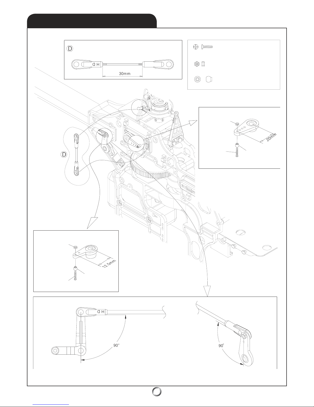
7.2
LINKAGES (STARBOARD)
27
M2.3x40mm Threaded Rod
SWASHPLATE
M2x8mm Phillips Head Screw (x2)
Stainless Steel Ball (x2)
SWASH SERVO ARM
T/R SERVO ARM
M2mm Hex Nut (x2)
M2mm
Hex Nut
Stainless
Steel Ball
M2x8mm
Phillips
Head Screw
M2mm
Hex Nut
M2x8mm
Phillips
Head Screw
Stainless
Steel Ball
T/R SERVO ARM
TAIL ROTOR PITCH
CONTROL LEVER
* PRO TIP: The goal is to avoid differential
throw and ensure a symmetrical throw from
full-left to full-right T/R throw. Neutral is
mid-T/C (throttle/collective) stick (hover for a
conventional setup), or 3/4 and 1/4 T/C stick
(upright and inverted hover). Hover position
is neutral, i.e. when both control arms should
be perpendicular to the pushrod
.
* NOTE: Use thread locker
on servo arm ball screws.
Page 28
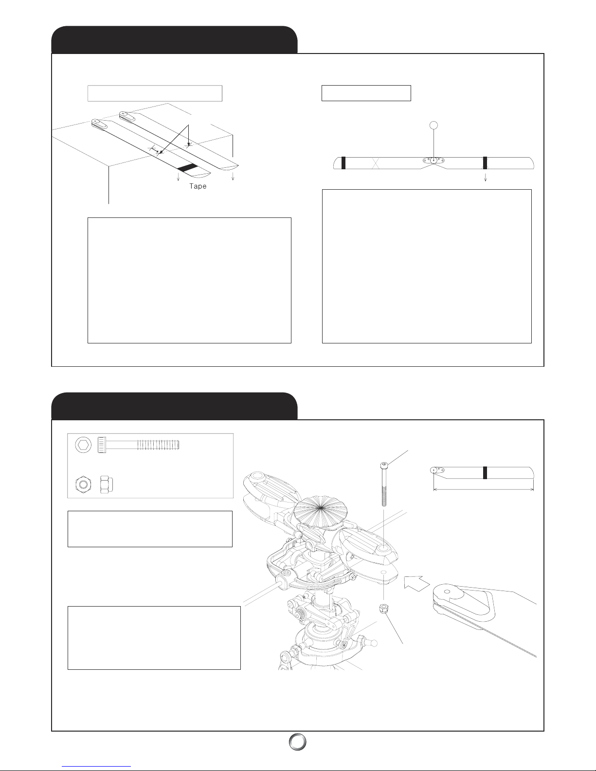
28
8.2
MAIN BLADES
BLADE BALANCE
8.1
M4x30mm Socket Head Shoulder Bolt (x2)
M4mm Nylon Lock Nuts (x2)
600mm
M4mm Nylon
Lock Nuts (x2)
* VERIFY: Ensure the leading edge is
forw
ard for clockwise main blade rotation.
* PRO TIP: The main rotor blades are tight
enough when you can move them by
hand, yet when you hold the helicopter on
its side (with the blades extended), they do
not swing loose from their own weight
.
Equalize Blade CG (center of gravity)
Equalize Blade Weight
Lightly mark CG of both blades.
M
* NOTE: Add tape at
the CG of light blade
until assembly hangs
perfectly level.
* PRO TIP:
Use a drop of
white paint on one blade
grip in which to always
install the same blade.
M4x30mm Socket Head Shoulder Bolt (x2
)
1. First figure out where the CG is for each blade and
mark it. The blade with the CG furthest from the
bolthole is the master blade - mark it M.
2. Next, add tape to the tip of the other blade until the
CG
point measures the exact same (from the bolthole)
as M. When the CG is the same as M’s, mark the CG.
* PRO TIP: The sharper the edge you balance the
blade on, the more precisely you can find the CG. A
single edge razor blade works great if you are both
patient and precise enough in your work.
Master (M) blade had CG
furthest from bolt hole.
Add tape (to move
CG outward) until
the CG is equal to M.
The next step is static balance - making both blades weigh
the same. In the first two steps we made the CG point of
both blades exactly the same. Now we must make both
blades weigh the same. The only way to add weight to the
lighter blade - and not affect the CG - is to add the ex
tra
weight on the CG of the lighter blade (tha
t’s why you
made the mark on both blades). Because manufacturers
make an effort to ensure both blades weigh the same, it
’s
likely you wo
n’t add tape to M -this technique will work for
individual blades from different packages, which do
n’t
weight the same to begin with
.
3. Assemble the blades on a table so they
’re perfect
parallel. Perform static balance by adding tape at the CG
mark of the lighter of the two blades until they hang level.
Further tips at:
www.audacitymodels.com
Add tape to lighter blad
e’s CG
* PRO TIP: Bolt them together with a
short length of 4mm Threaded Rod
plus a pair of 4mm Flat Washers and
4mm Hex Nuts (not supplied).
* PRO TIP: For wood
blades,
remove the blade
covering material, and use
thick cyanoacrylate glue
to join the plastic par
ts.
Page 29
29
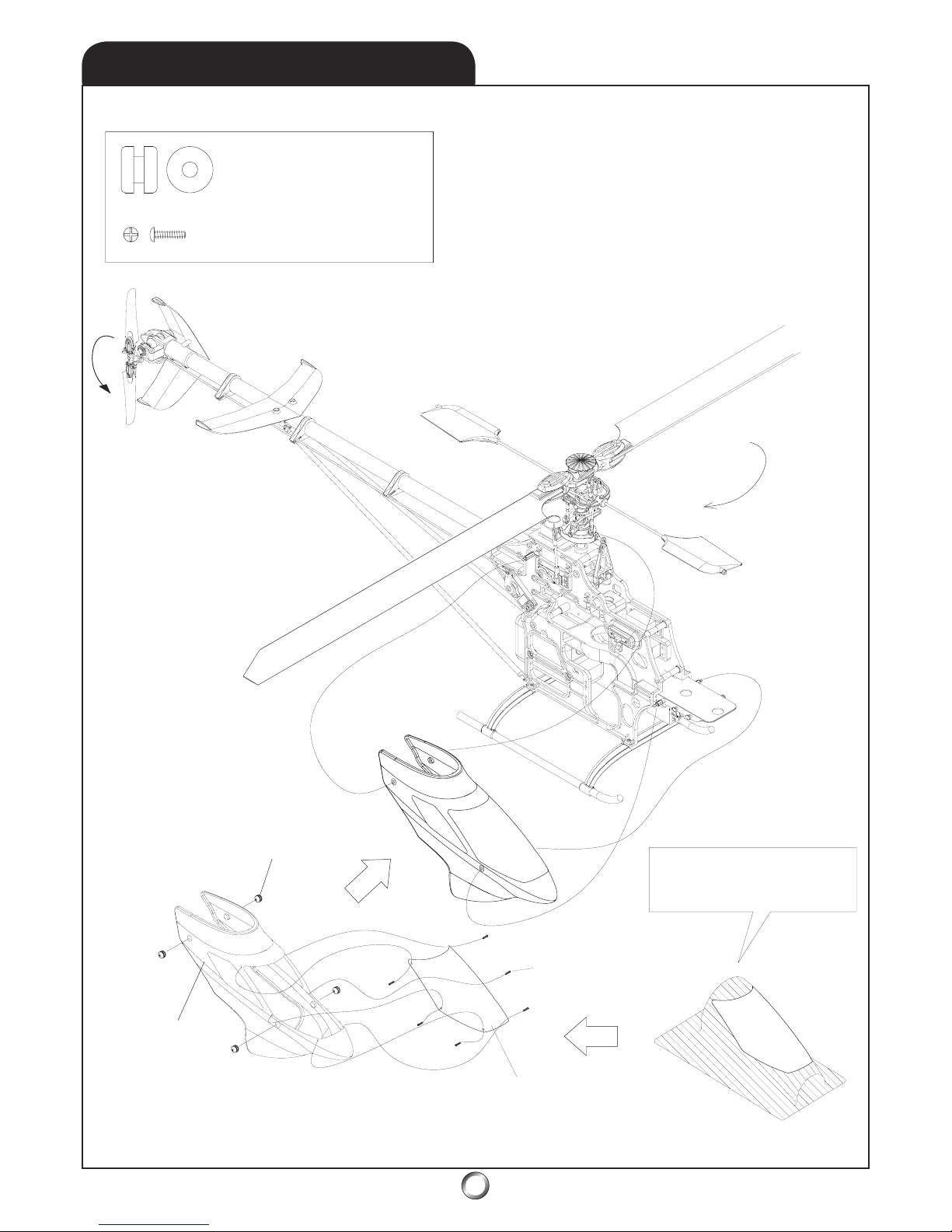
8.3
CANOPY & WINDSHIELD
Canopy Mount Grommets (x4)
M2x8mm Self-tapping Screws (x6)
Canopy M
ount
Grommets (x4)
M2x8mm Self
Tapping Screws (x6)
Canopy
Windshield
* NOTE
: Cut to the molded trim
line using Lexan-type scissors and
fasten with self-tapping screws
.
* NOTE:
Clockwse
main rotor rotation
.
* NOTE: Countercockwse
tail rotor rotation
.
* NOTE: Use small drill bit or auger to make holes.
Page 30
30
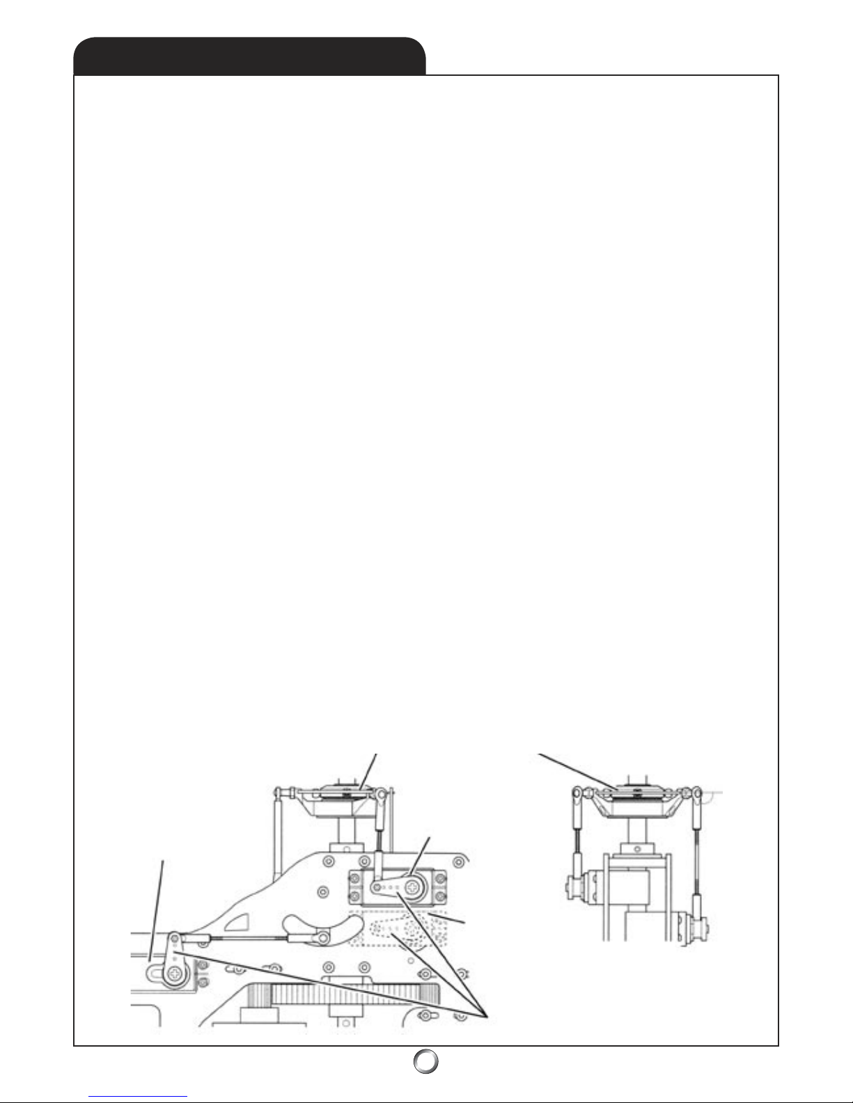
For the Tiger 50, the steps are first a symmetrical
mechanical set-up followed by any adjustments
for the lighter duty needs of the upright regimen
(accomplished in the radio). It doesn’t get easier
than this!
CYCLIC & COLLECTIVE - MECHANICAL SET-UP:
Mechanically it’s more important to have CCPM
linkages at their respective neutral position in
a model set up for symmetrical flight. You can
later adjust your model for a predominantly
upright flight regimen simply by using the radio
system. The converse - setting up mechanically
for upright flight and using the radio system
to adjust for a symmetrical set-up isn’t a sound
practice.
The Tiger 50 helicopter is designed for a full-on
switchless-inverted symmetrical set-up from the
beginning - there are no compromises for the
more rigorous 3D duty! By the way, there’s still a
switch to throw during flight, but the switch referenced doesn’t mean the same thing. The term
switchless inverted is a holdover from days when
flipping a switch actually reversed the controls!
The steps are the same for all models, regardless
of intended duty - be it extreme performance,
or sport. Building the linkages per sections 7.1
and 7.2 means all the mechanical linkages will
be at the neutral position when the control sticks
are in their neutral position. All that is left is to
ensure that each servo arm is at its respective
neutral positions - 90o to the pushrod. (Figure 1)
This segment of the manual deals with setting
up your helicopter in preparation for flight. The
set-up includes both mechanical and electronic
adjustments to the model.
There are two prevailing schools of thought
regarding model helicopter set-up. One sets up
a helicopter primarily oriented for upright flight.
The other sets up the helicopter for symmetrical
flight - this simply means the model is as liable
to hover inverted as upright. This flight regimen
is also known as extreme aerobatics, or 3D flight.
If you are a beginner, you will have an easier time
of learning to fly with a set-up oriented toward
upright flight because there is a greater range
of pitch to throttle/collective (T/C) stick motion.
The T/C stick travels between low and high pitch
and hover occur with the T/C stick in the middle
of the full range (the model’s usually upright).
Extreme performance pilots, on the other hand,
demand a set-up which is fully symmerical, i.e.
one in which 0o pitch occurs in the middle of the
T/C stick range (instead of hover) and full T/C
(max) pitch occurs at both ends of the T/C stick
range (in both the positive and negative pitch
directions). Upright hover thus occurs at 3/4 T/C
stick and inverted hover at 1/4 T/C stick. This
flight regimen is more difficult for the beginner
to manage as the range between mid-stick (0o)
and maximum (+) pitch is compressed by half.
Of course, we assume beginners won’t be trying
any inverted maneuvers - on purpose that is!
Swashplate is level both
fore/aft and side-to-side
Swashplate servos are at
neutral and the pushrods
are 90o to the servo arms
Servo plugged
into channel 1
Servo plugged
into channel 2
Servo plugged
into channel 6
Figure 1
9.0
SET-UP TIPS
Page 31
31
9.1
SET-UP TIPS - CONT.
While mechanical methods, or even 4-servo
CCPM are very practical methods of inputting
controls to the swashplate system (fore/aft
cyclic, side-to-side cyclic, plus collective), greater
overall system precision and reliability results
from the use of 3-servo CCPM. That’s largely
because mechanical systems have much greater
slop, or play in the system - which increases with
wear. However, servo failure is more likely than
mechanical failure. Thus, inherent in the design
of the Tiger 50 is the elegantly very simple to
understand concept of reducing the number of
parts in the model to increase reliability (fewer
things which can possibly fail). As it turns out,
this holds true for the electronics as well - hence,
it’s easy enough to see where failure of a system
with 3 servos is 33% less likely than one with 4.
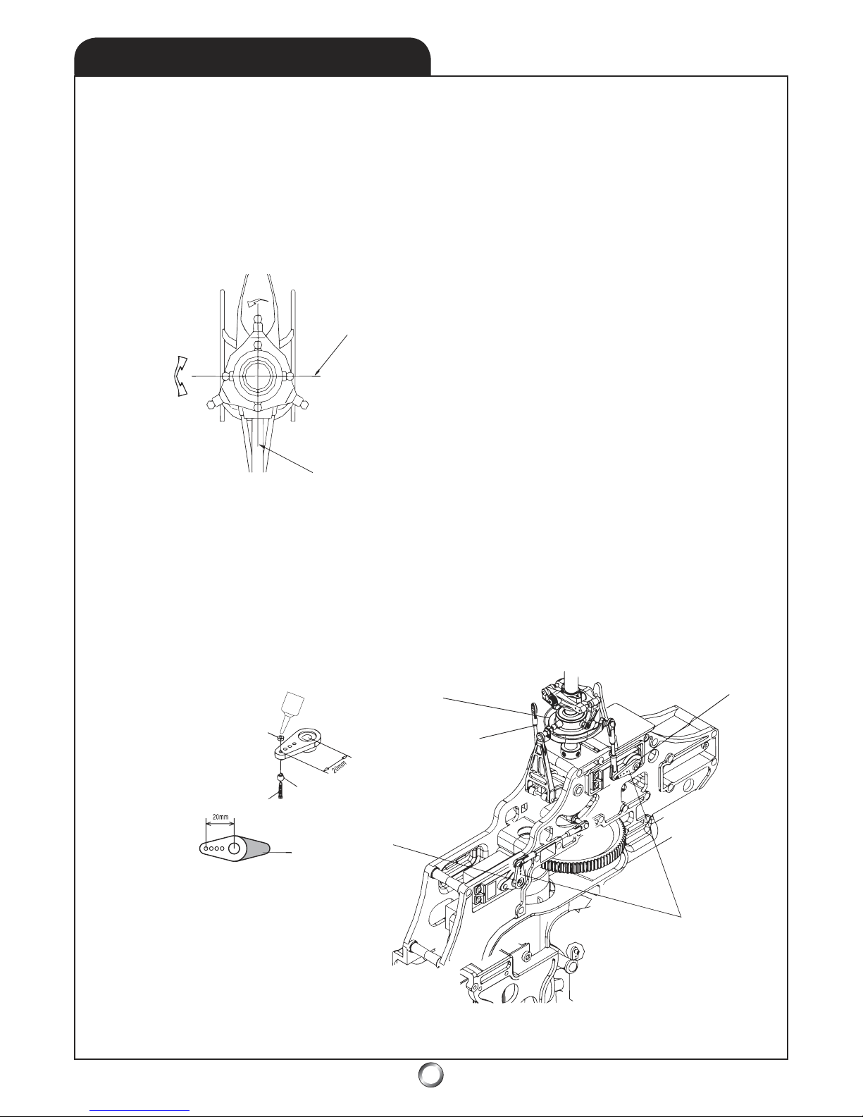
Mechanical set-up is very important insofar as
ensuring the linkages form 90o angles to the
servo arms at neutral. Equally important is the
idea of mechanical leverage. An even application of leverage to the bearings of the servo
occurs when the ball links are installed on the
inside face of the three CCPM servo arms at a
distance of 20mm from center. (Figure 3)
Perpendicular to
the tail boom
Parallel to the
tail boom
Figure 2
Cyclic linkage
(starboard)
Swashplate
Fo
re/aft servo
Cyclic
servo
(por
t)
Fore/aft and
cyclic servo arms
M2mm Hex Nut
Stainless Steel Ball
M2x8 Phillips Head Screw
Trim ex
cess
servo arms
(optional)
* NOTE: Use thread locker
Figure 3
* NOTE: Stainless balls are installed
on the underside of the servo arms.
Look down on the swashplate from above and
it is apparent the Tiger 50 uses a 120o eCCPM
system as there are three servos (spaced at 120o)
controlling the outer ring of the swashplate. The
inner ring, however, is spaced at 90o per usual
convention. (Figure 2)
Page 32
32
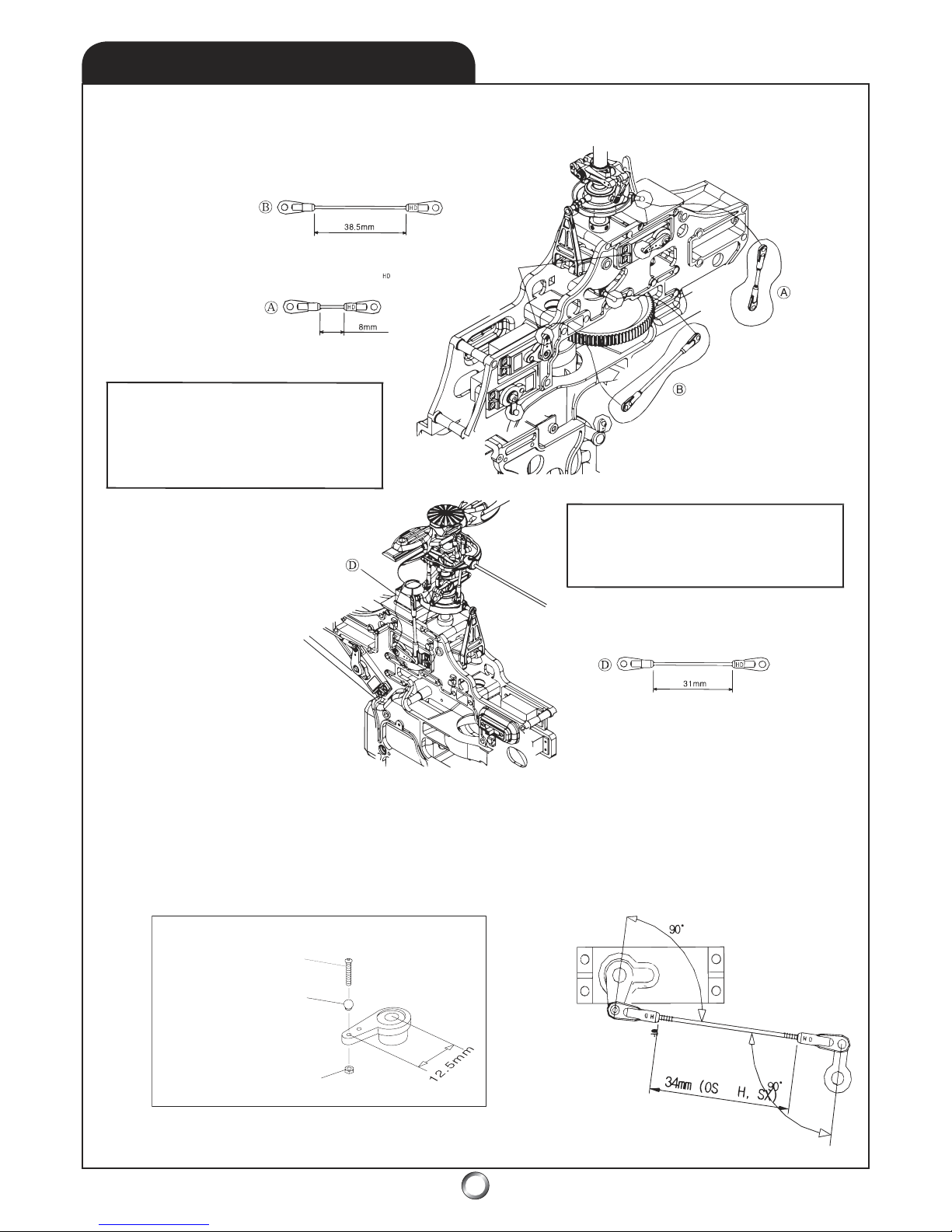
THROTTLE - MECHANICAL SET-UP:
Mechanically setting up the throttle is next. The pushrod length shown for neutral position is approximately the hover throttle opening also, but this dimension is really taken to be mid-point between
WOT and idle (not fully closed). This means you set it up with this length, but plan to adjust it after
the helicopter has been flown - but before making really precise electronic adjustments to the throttle
curves. (Figure 5)
SET-UP TIPS - CONT.
9.2
* NOTE: HD ball-links are uni-directional.
This means the side of the link that has
HD on it must always face the side of the
ball which has the screw head.
Verify pushrod lengths for the three CCPM servos. Also verify the HD-mark on each of the plastic ball
links face the screw-head side of the ball. (Figure 4)
* NOTE: Ensure the pushrods (linkages)
for the fore/aft servo, both side-to-side
cyclic servos, as well as the T/R (tailrotor)
pushrod are 90o to the servo arms when
at their neutral positions.
Figure 4
Figure 5
T/R Servo
Ar
m
M2mm Hex Nut
M2x8mm Phillips Head Screw
Stainless Steel Ball
675mm
Throttle
Servo Arm
M2x8mm Phillips
Head Screw
Stainless Steel Ball
M2mm Hex Nut
50
* NOTE: Dimensions given for OS Max 50 SX-H at middle of travel - this is neutral position
for linkage. This is between WOT and idle - not between WOT and completely closed .
* NOTE: Dimensions given are for hover as the neutral
position for linkage. This is not with T/R blades at flat or 0
pitch, it’s at hover pitch.
o
Page 33
33
SET-UP TIPS - CONT.
9.3
T/R Servo
Ar
m
M2mm Hex Nut
M2x8mm Phillips Head Screw
Stainless Steel Ball
675mm
* NOTE: Dimensions given are for hover as the neutral
position for linkage. This is not with T/R blades at flat or 0
pitch, it’s at hover pitch.
o
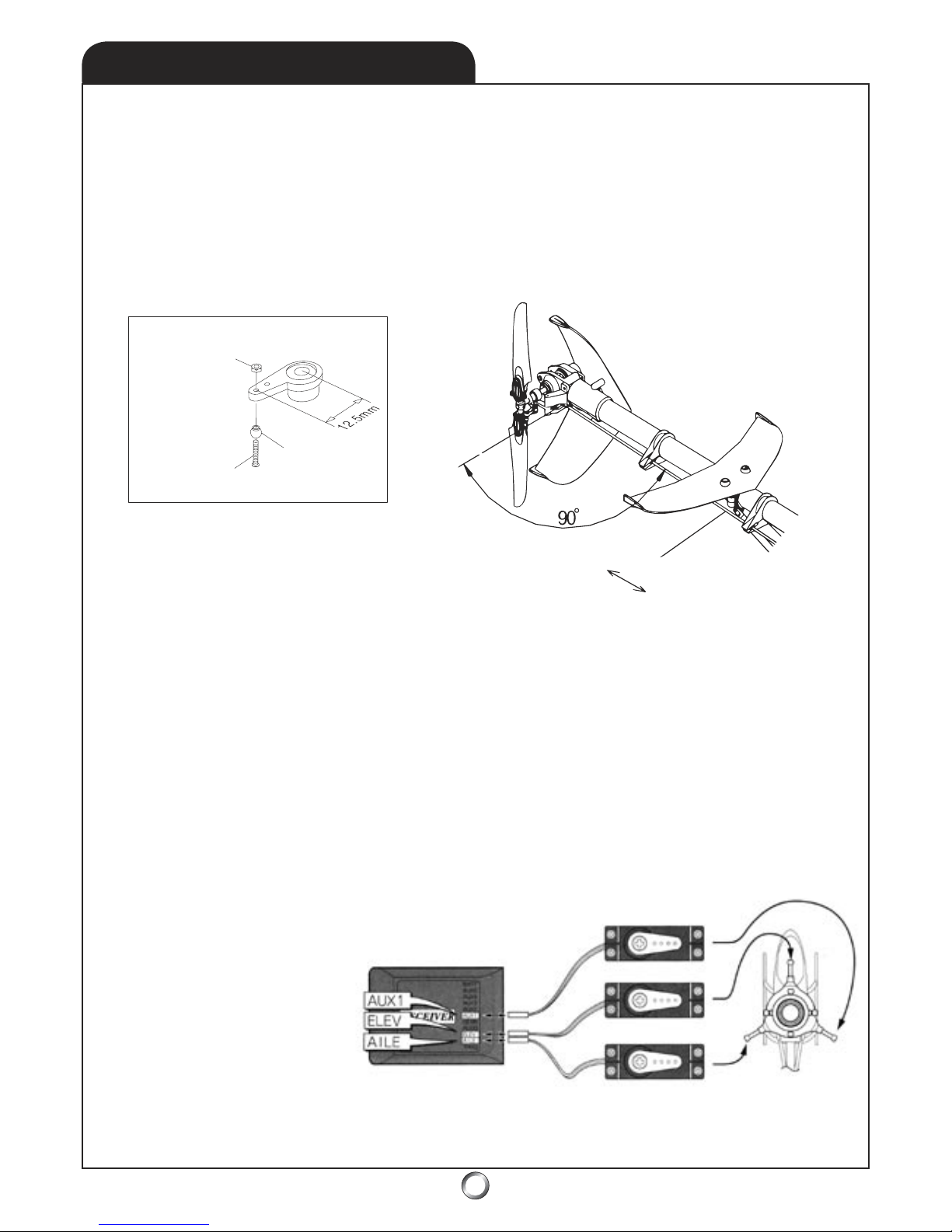
TAIL ROTOR - MECHANICAL SET-UP:
Mechanically setting up the tail rotor (T/R) is next. The pushrod length shown for the neutral position
is for hovering. Again, this is the point at which both tail rotor control arm and tail rotor servo arm
make a 90o to the tail boom. We keep harping about this because otherwise instead of symmetrical
throw in the linkage, there is differential throw. This means different motion (more to one side than
the other) on each side of neutral - it makes flight and adjustments less predictable. Again, as with
the throttle linkage, this given length is a starting point - you may need to make slight adjustments
after flying the helicopter model. Also, if you are using a heading-hold or heading-lock gyroscope, this
dimension is quite likely accurate enough as is and will not need further adjustment. (Figure 6)
Figure 6
ELECTRONIC SET-UP: Introduction
While we like to think the sequence is to always perform an electronic set-up after mechanical set-up,
in fact, the processes interact to a certain degree. For example, in order to perform the mechanical
set-up we need for the servos to be plugged into their respective channels and for each servo to be
centered, or in its neutral position. We are aided in this process somewhat because we know how
long to build each pushrod (for the theoretical center). However, reality intrudes as despite the best
efforts of world class engineers and manufacturing processes, the practical effect of the end user
installing servos from different manufacturers (and even accessory servo arm manufacturers) means
in effect we’re really giving you a really close point from which to start making slight tuning adjustments. The more precisely the neutral position for each servo is set, the closer the initial set up will
be to the final set-up. In any case, the mechanical and electronic set-up we suggest will be close
enough to permit successful test flights from which fine tuning can depart. Next, consult with the
radio system’s manual and verify the three CCPM servos are plugged into the receiver - something
like this. (Figure 7)
Do the same for the throttle and tail rotor servos - as well as the gyroscope, the switch harness, and
the flight pack battery. Once that’s done, ensure you’ve routed the antenna via the antenna tube (3.1)
and protected the avionics from vibration (6.4).
Figure 7
Page 34

34
SET-UP TIPS - CONT.
9.4
ELECTRONIC SET-UP: Background
We’ve discussed the two predominant flight
set-ups; one oriented for upright flight and
other oriented to symmetrical flight. We’ve also
touched on the concept of pitch and throttle
curves. Let’s elaborate on all this a bit.
As it turns out, the pure symmetrical set-up is
fictional since helicopters initiate and end flight
with the engine at idle and the rotor blades
stopped. Thus, the symmetrical set-ups shares
similarity to the upright oriented set-up in
what’s called the Normal Flight Condition, or
Normal Mode. However, first let’s review how a
helicopter flies before we proceed.
For a helicopter to fly it depends on the lift
generated by the rotating main blades. These
blades are tilted at an angle, just like a fan or a
propeller has an angle and hence, as they spin,
they move air. Introduce a positive angle into
the blades (leading edge higher than the trailing
edge) and they produce lift because they push
the air downward while simultaneously lifting
the helicopter off the ground. The more angle,
the faster the helicopter is lifted. But in practice,
the practical amount of angle is limited by two
things, the horsepower available to spin the
main rotor and the angle at which the blades
will stall, or stop producing more lift than drag.
More on this later.
Similarly, if you introduce a negative angle (or
negative pitch as it’s more commonly referred
to) into the rotor system, the helicopter will
push the air upwards forcing the model onto its
landing gear. From this simple fact derives the
idea that negative pitch combined with a model
whose orientation is upside-down and we have
the basis for inverted flight. As it turns out, the
helicopter doesn’t care whether it’s right side-up
or upside-down!
Examine the airfoil of the main blades and you’ll
see a strong resemblance to the airfoil of a wing.
That’s because it is a wing! In fact, it’s really not
uncommon to refer to helicopters as rotary wing
aircraft vs. airplanes known as fixed wing aircraft.
Control of the helicopter is established through
the introduction of additional angles of pitch
(both positive and negative) within the overall
gross angles we mentioned earlier. Let’s look at
an example.
Suppose a helicopter uses 5.5o of pitch to hover
(the converse holds true as it would use about
the same, or -5.5o i.e. negative pitch to establish
a hover inverted and thus, the convention is
introduced of indicating when pitch is negative,
otherwise, it’s assumed to be positive). Anyway,
from a hover, for the helicopter to move forward,
the linkages of the rotor system would introduce
a little bit more pitch on one side of the rotor
disk and remove a bit of pitch from the other.
These result in a tilting of the entire rotating
disk forward - which would cause the helicopter
itself to also tilt forward and thus, move forward.
Coming to a stop would entail the reverse, or the
tilting the disk aft.
R/C model helicopters use a combination of Bell
and Hiller mixing to provide both direct and
indirect control over adding and subtracting
the small amounts of pitch involved in controlling the rotor disk. It is beyond the scope of this
manual to enter into greater technical depth.
Let’s return to the idea of blade angles, or pitch,
as they relate to stalling the blades.
As it turns out, depending on the airfoil, a blade
(or a wing for that matter) stalls between 14o
and 18o of pitch, or angle of attack (how much
higher the leading edge is related to the trailing edge). Because the main rotor may have as
much as 10-11o of pitch during maneuvers, and
because the addition of control inputs will increase the pitch on one side of the rotor disk by
as much as 5-6o (whilst simultaneously reducing
the pitch on the other side, of course - but we’re
only concerned with where the blade stalls), we
need to beware the possibility of stalling part of
the main-rotor disk (causing an extended loss
of symmetry in lift). The reason for touching on
this is related to the extreme power of 50-class
engines when coupled with the agile airframe of
the Tiger 50 helicopter which means if you are
not careful, you may find yourself on the wrong
side of the limits imposed by physics! In short,
be aware of the fact that there are limits.
Page 35
35
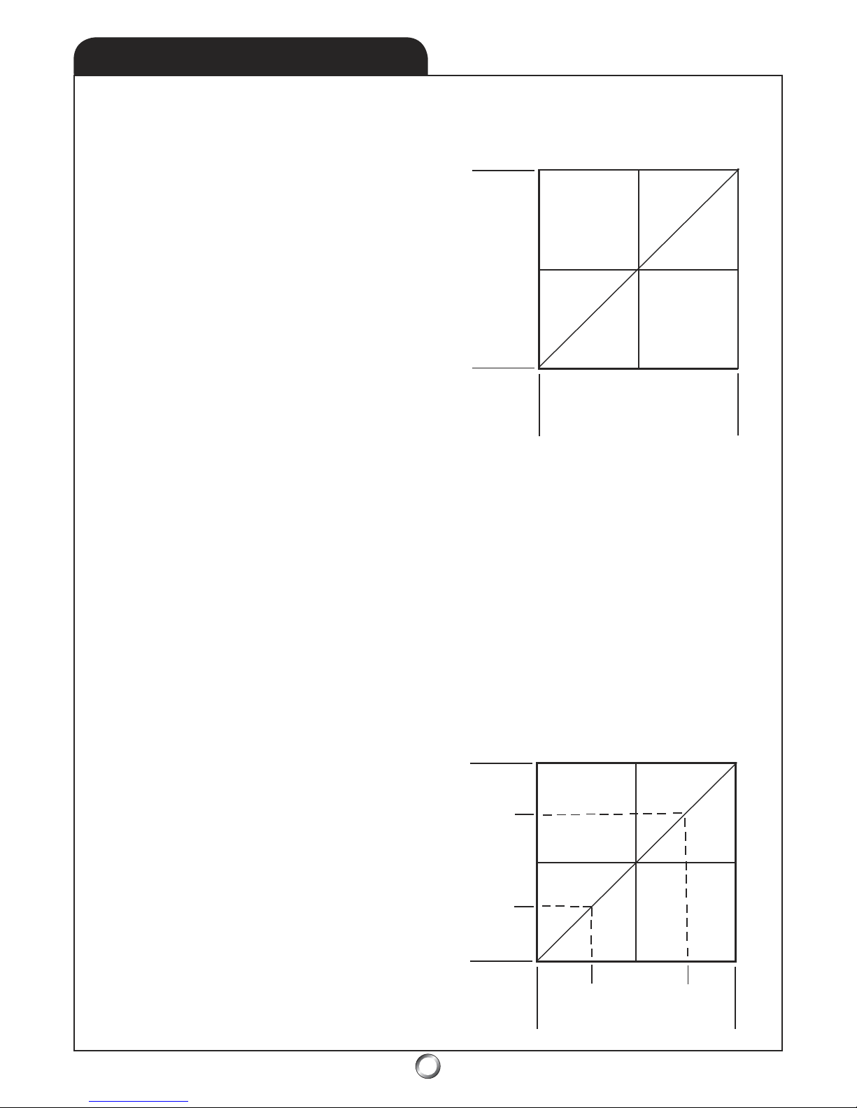
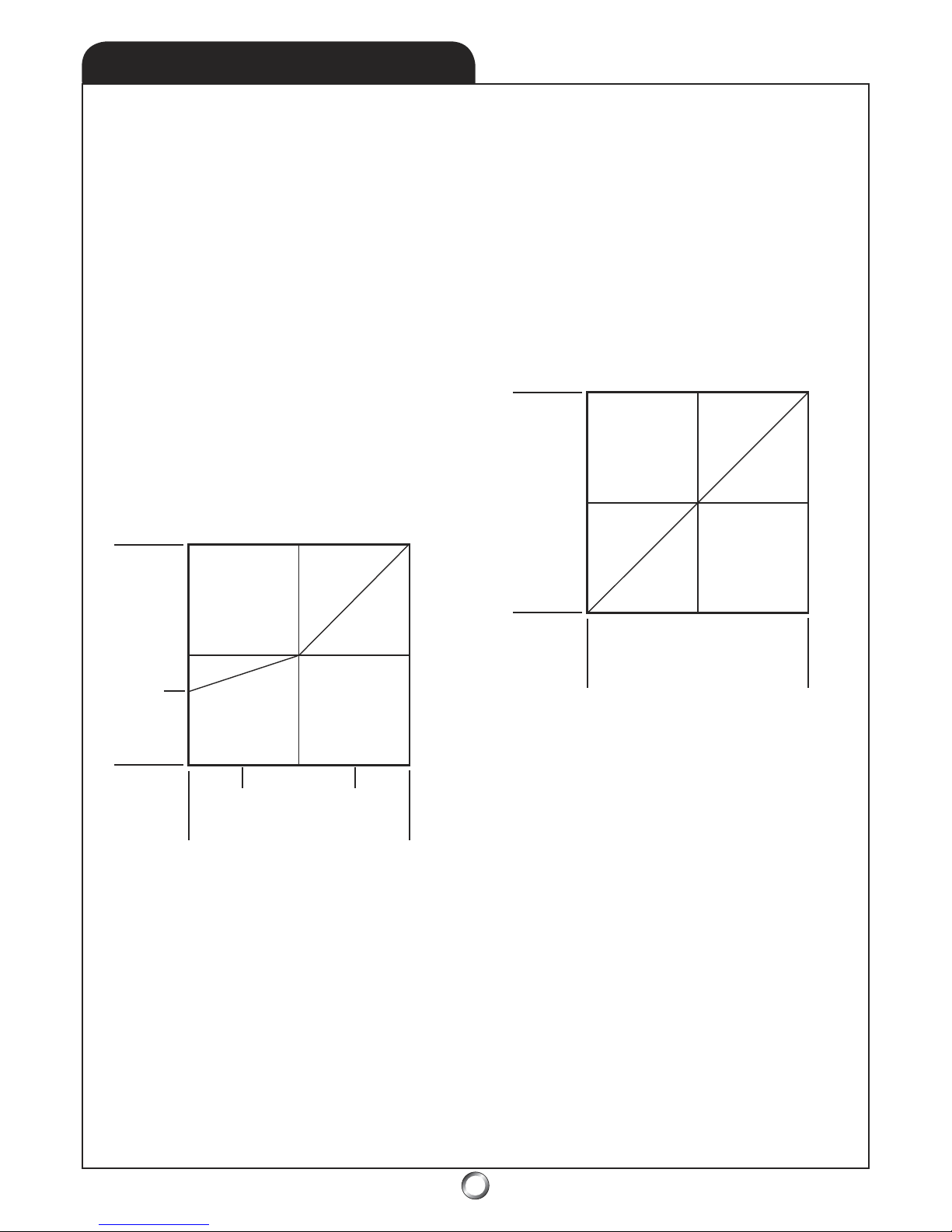
Below, the pitch curve represents the pitch
range from 11o to -11o with mid-stick being 0o.
This is the pitch curve of a helicopter, which can
perform equally well inverted and right side-up.
Either extreme of the joystick represents 11o of
deviation from 0o and the upright hover occurs
around 3/4-stick while the inverted hover occurs
at about 1/4-stick, both with 5.5o pitch. (Figure 9)
SET-UP TIPS - CONT.
9.5
ELECTRONIC SET-UP: Pitch Curves
We suspect that in the course of learning about
model helicopters you’ve heard the term pitch
curve or throttle curve bandied about. All that’s
meant by this is the graphical representation of
what happens to a control (servo) when a stick
on the transmitter is deflected (moved). Let’s see
if we can shed some light on this. We’ll begin
with pitch curves since they’re easy to visualize
and they relate to orientation (upright or symmetrical set-up).
First some terms and definitions - so that we’re
all on the same page. We start by assuming you
are using a Mode 2 setup in your transmitter.
This is Throttle/Collective as well as the Tail Rotor
on the left-hand control stick and the fore/aft
as well as the side-to-side cyclic controls on the
right-hand control stick. Holding the transmitter
in both hands and moving the T/C stick towards
you will decreases throttle and collective pitch
while moving it away, or up, increases T/C pitch.
T/C servos are linked electronically. Push the
tail rotor stick to the left and the nose of the heli
goes to the left - and vice versa. The rotation
caused by the T/R is about the axis of the main
rotor, i.e. the helicopter will spin around in circles.
The right-hand joystick controls cyclic pitch
(which is the adding and subtracting of pitch
from the collective pitch). Cyclic pitch tilts the
rotor disk and causes changes in direction.
Side-to-side, or aileron, cyclic causes rotation
about the longitudinal axis (the length - or tail
boom axis) so the machine will roll. As you
would expect, move the joystick to the right and
the machine will roll to the right. In a similarly
fashion, the fore/aft directions for the joystick (or
control stick) causes the machine to roll about
the fore/aft axis. Pushing the joystick away from
you dips the nose and a pull towards you raises
the nose. Continue to hold the control and the
helicopter will rotate in place about that axis
(when combined with the well timed and skillful
application of collective pitch in both positive
and negative directions as well as some T/R to
hold position). Did you expect this to be easy?
It’s not - which is why there are more fixed wing
pilots than rotating wing pilots! But you can
master it.
So what does a pitch curve look like? This is what
a collective pitch might look like. (Figure 8)
If you’re thinking, That’s not a curve, that’s a
straight line! You’re right as in this case, the pitch
curve is a straight line. It’s an example of the
pitch curve for a switchless inverted set-up. Let’s
put some numbers to the curve to see if it helps.
Low
Stick Position
Servo Position - Pitch
Low
High
High
Figure 8
Pitch Curve
Stick Position
Pitch
Figure 9
11
o
-5.5
o
0
o
Hover
Inverted
Hover
1/4
3/4
1/2
-11
o
5.5
o
Idle Up 1 - switchless inverted
Page 36
36
SET-UP TIPS - CONT.
9.6
The shorthand for the pitch curve in Figure 9
would be -11, 0, 11. It would be understood that
we meant -11o ,0o ,11o but the degrees could
just as easily be left off. The proper name for the
curve in Figure 9 would really be:
Switchless Inverted Pitch Curve, Idle Up 1
The Switchless Inverted part you already understand to mean a set-up for symmetrical flight,
while Pitch Curve is now self-explanatory. The
Idle Up 1 part refers to the flight mode used for
most aerobatics. Depending on the brand radio
you select, these names may be different . . .
Futaba-brand radios may refer to Idle Up 1, or I1
and JR-brand radios may refer to Flight Mode 1
. . . but they both mean the very exact same
thing!
This brings us to something else. Your radio may,
in addition to these flight modes, refer to others
like Hold Condition, or Hold Mode, and Normal
Condition, or Normal Mode, and even Idle Up 2,
or Flight Mode 2. We’ll get to these later.
By the way, Futaba uses the Flight Condition
while JR uses the word Mode - but we figure they
really just do it to confuse us! Don’t worry if you
hear people referring to Mode this or Mode that
but you notice they fly Futaba equipment - it just
means they’ve been hanging around folks who
use JR equipment - it’s not a sin! Plus, of course,
there are other brands too - like Airtronics, Hitec,
et al. and each have proprietary terminology
you’ll need to get the hang of.
Oh, and in case you’re wondering, no we’re not
going to teach you how to program a specific
radio to the Tiger 50 in this manual. There are
too many radio systems with excellent manuals
which explain exactly how to set-up a CCPM heli
for us to replicate all their work. That, plus the
radio models change almost yearly, so anything
we put in the manual would soon be obsolete!
Instead, our goal is to give you a grounding in
both how and why certain flight modes exist,
combined with some pitch values - which will
get your helicopter close to a final set-up - close
enough to fly and just make minor trim changes.
As you may suspect, this section was created for
folks to whom this is all new. Experienced pilots
will just glance at the pitch values we suggest
and be on their way without a further glance at
this manual!
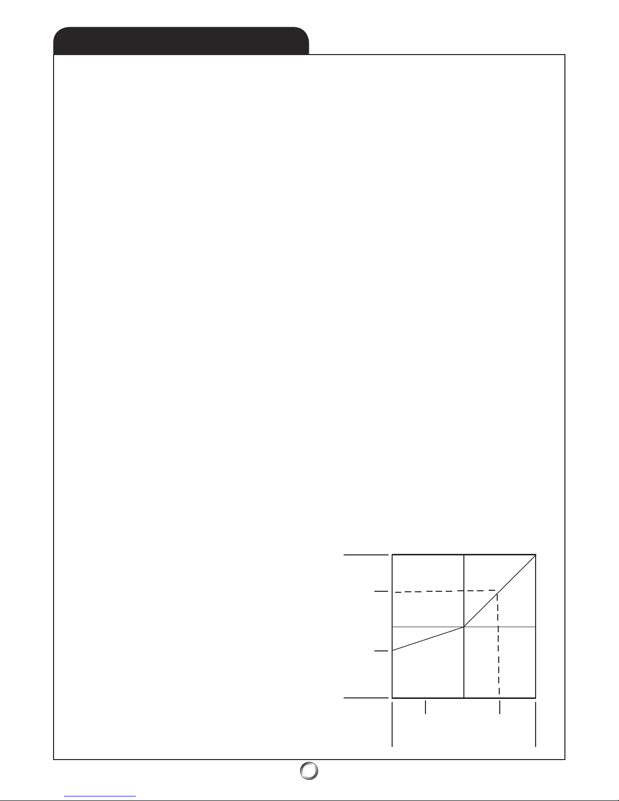
Since we’ve discussed the switchless inverted
pitch curve Idle Up 1 set-up, let’s discuss the Normal Pitch Curve for the same set-up. The Normal
Pitch Curve is the one used to start the chopper,
carry it to the flight line, and take-off as well as
for recovery of the model at the end of a flight.
Flying around is done in Idle Up 1 - understand?
The goal is for this curve to exactly match the
Idle Up 1 curve from mid-stick on up because
you don’t want the heli to jump up or down
when you engage the switch due to a difference
in pitch curve profiles. Thus, the top end pitch
will be the same; the hover pitch will also be the
same (and will still occur at 3/4 stick - exactly
as it does for idle Up 1). Similarly, mid-stick will
continue to be 0o of pitch. The differences in the
pitch curve will only be apparent in the run up
to hover. The end result will be a smooth transition between the Normal Mode and the Idle Up
1 flight mode, which can be accomplished from
hover pitch on up. At the bottom of the pitch
range, there will be about -4o of pitch to enable
easy landings even in a stiff breeze (Figure 10)
Stick Position
Pitch
Figure 10
11
o
-4
o
0
o
Hover
1/4
3/4
1/2
5.5
o
Normal & Hold - switchless inverted
Page 37
37
SET-UP TIPS - CONT.
9.7
By the way, if it’s not clear, you measure pitch at
the blades with a pitch gage while ensuring the
flybar is absolutely level. Your hobby dealer will
have pitch gages available. With a switchless
inverted set-up, there’s not often a need for a Idle
Up 2 Flight Condition. Some expert pilots who
use the condition often mimic Idle Up 1 so as to
not have problems if they inadvertently toggle
the switch past the Idle Up 1 position. Other expert pilots will have almost the exact same curve
loaded but with slight changes to suit perhaps
greater wind. We’re treading on the territory of
professionals. If you don’t know why you would
want an Idle Up 2 (in additional to an Idle Up 1),
you likely don’t need to worry about it.
This brings us to the Hold Condition. We recommend the Hold Condition pitch curve should
look identical to the Normal Curve. The Hold
Condition is used for practicing autorotation
landings - simulated engine out landings.
The end result is you will have the ability to
switch between flight modes, be it Normal, Idle
Up 1, (or 2), and Hold without the helicopter
doing anything strange. What’s more, you can
always find the unloaded point on the rotor disk
(0o) because it’s mid-stick for every single flight
condition. This is a tremendous advantage in
flight management and will permit the easiest
way to master aerobatic flight with the Tiger 50.
At this point you may be wondering how do you
decide what the top end pitch will be? This is
determined by the power of the engine. Some
engines being stronger than others can pull 11o
of pitch with no problem, others can only pull
(without sagging) 10.5o of pitch, etc. It depends
on the engine. However, while we can directly
measure the pitch of the main rotor, we don’t
have an easy way to measure power output. The
easy answer to this is max pitch corresponds to
max throttle opening. Usually. The top-level
aerobatic pilots however keep a little in reserve
at top end pitch so they can add more power
to make up for the cyclic demands of pitch and
power during maneuvers - but that’s beyond the
scope of this manual. We’ll get into all this a bit
later when we discuss Throttle Curves.
We’ve pretty well covered the pitch curves for an
experienced pilot who wants to perform any 3D
maneuvers within their repertoire.
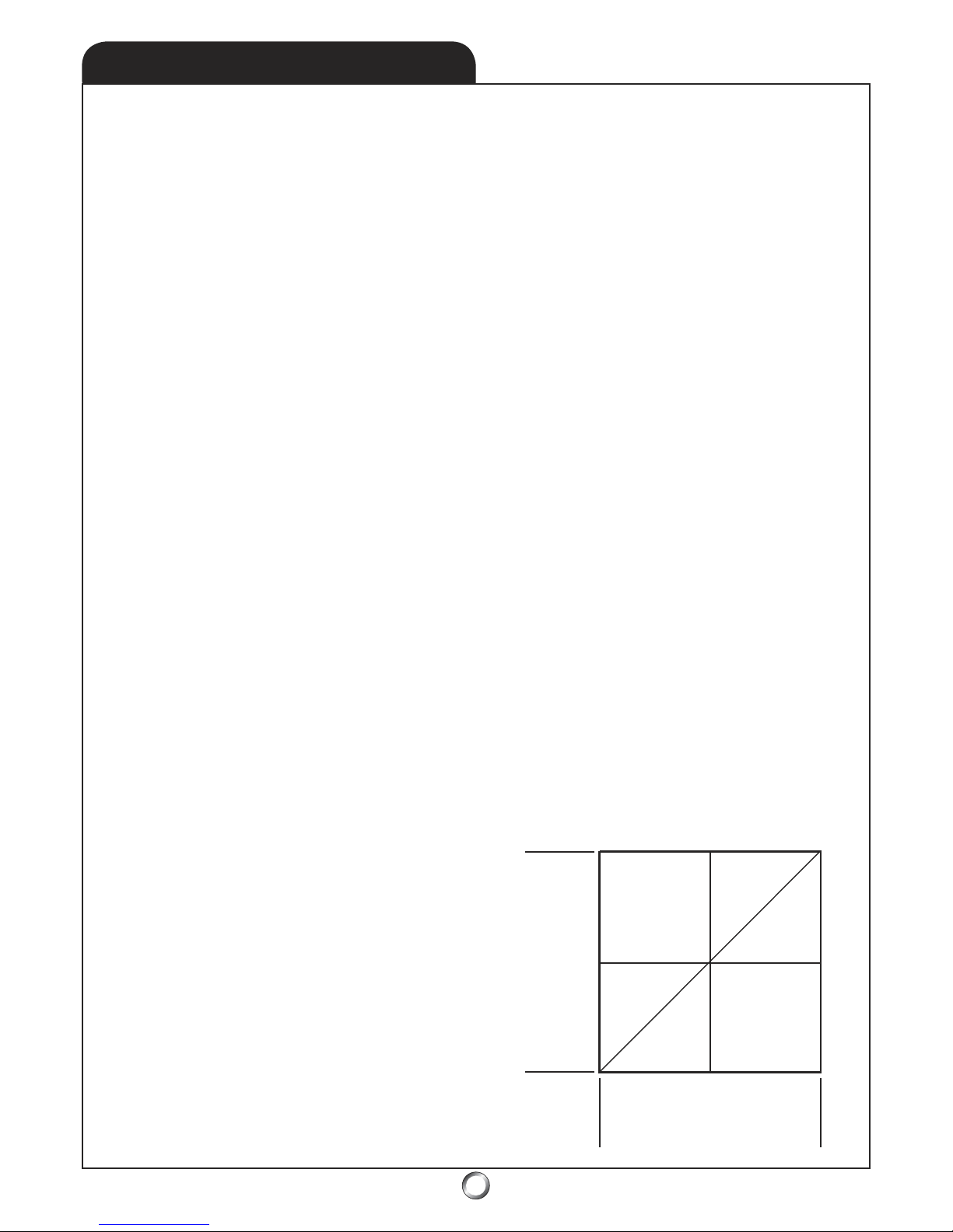
Upright Orientation: Normal Pitch Curve
Next we’ll discuss the minor changes made to
the pitch curves for the pilot who is not really
interested in extreme aerobatic flight. First up
is the Normal Pitch Curve (for upright oriented
flight). As you’ll see, the curve really doesn’t look
very different at all, but the values are quite a
bit different as the hover point now occurs at
mid-stick. In fact, this is a much better set-up
for hovering as the sensitivity of the T/C stick is
reduced by half! Top end pitch is not changed
either. Bottom end pitch is changed to the
negative value of the hover pitch. In this case,
it’s -5.5o (though some pilots may not like the
bottom end pitch quite so steep, it does allow
greater precision and control for spot landings
by adding the ability to drop quite steeply by
adding loads of negative pitch).
By the way, have we mentioned just how easy it
is to make the changes to the curves? It’s done
simply by changing the ATV (total amount of
servo throw) for each of the three CCPM servos. Of course this is done with the pitch gage
installed on the blade so you can interactively
make adjustments. It’s quite easy and takes only
a few minutes to program into the transmitter!
(Figure 11)
Stick Position
Pitch
Figure 11
11
o
-5.5
o
Hover
1/2
5.5
o
Normal & Hold - upright orientation
Low
High
Page 38
38
SET-UP TIPS - CONT.
9.8
ELECTRONIC SET-UP: Throttle Curves
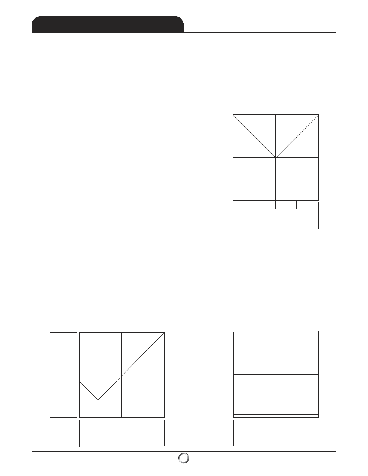
As with pitch curves, throttle curves are just the
graphical representation of servo position as
it relates to stick position. In this case, the stick
is the T-part of T/C, or throttle. High stick corresponds to high pitch. The throttle curve for
a Normal pitch curve might look like the one
below. Notice, how the throttle is closed at low
stick and wide open (WOT) at high stick and
somewhere in the middle for mid-stick, or hover.
(Figure 13)
You may have noticed the T/C stick is no longer
symmetrical for the Normal Curve in an upright
oriented system because there’s 11o of pitch between low pitch and hover and only 5.5o of pitch
between hover and high pitch. Earlier we mentioned many pilots don’t like the low end of the
pitch range setup so sensitive. This is very easy
to adjust with the transmitter by decreasing the
low-end ATV values of the three CCPM servos.
Below is another Normal Pitch curve - one that
many pilots may find more comfortable. However, be aware that in high winds, it may be harder
to get the helicopter back down because you’ll
find a need for more and more negative pitch
as the wind speed increases. In fact, in a stiff
breeze, a helicopter with only 0o of pitch, seemingly doesn’t want to come down! (Figure 12)
For an upright, or sport, orientation, there’s also a
need for an Idle Up 1 Pitch Curve because while
the helicopter spends most of its time upright, it
doesn’t spend all its entire time upright. This heli
will occasionally perform both loops and rolls
during which it will be briefly inverted. What
does the Idle Up 1 Pitch Curve look like for a
machine with a sport orientation? Exactly like
the one above! The difference isn’t in the pitch
curves but in the throttle curves. Why? Because
it’s critical to always maintain rotor speed, most
especially when the helicopter is in the inverted
portions of the maneuvers. This leads up to
discussing throttle curves.
Stick Position
Servo Position - Throttle
Idle
WOT
High
Figure 13
Throttle Curve
Low
The whole idea of throttle curves is for the throttle to add or subtract power to the main rotor
system (by opening or closing the throttle) so as
to maintain the RPMs of the main rotor constant.
Seems simple enough as increasing main blade
pitch means you increase the load, which would
slow down the main rotor blades unless we also
increased the throttle. Similarly, reducing the
load on the main rotor system by reducing the
pitch would lessen the load on the engine which
is compensated for by closing the throttle the
appropriate amount - understand? Hence, the
reason why we refer to the throttle collective
stick as the T/C stick is because the throttle and
the collective pitch move at the same time, or
are linked. Usually.
Usually? Yes, the usual relationship means high
pitch and high throttle while low pitch is linked
to low throttle. But there are times when this
isn’t the case - during Idle Up and Hold.
Stick Position
Pitch
Figure 12
11
o
-3
o
Hover
1/4
3/4
1/2
5.5
o
Normal & Hold - upright orientation
Page 39
39
SET-UP TIPS - CONT.
9.9
Throttle Curves: Idle Up and Hold Conditions
While the throttle and the collective pitch servos
move at the same time, or are linked, for Normal
pitch curves, as soon as a helicopter is inverted,
the pitch servo moves in the opposite (negative)
direction. If the system closed the throttle it
would mean disaster, as the rotor speed would
decay! Similarly, to practice autorotation, the
pilots wishes to disconnect the throttle from
the collective stick, in effect setting the engine
at idle while permitting the pilot to perform the
autorotation maneuver as if the engine had died.
Then, if the maneuver isn’t coming along well,
the pilot flips the hold switch back, the engine
roars back to life from idle, and the helicopter
can enter normal flight again. Both of these are
conditions where the linking of throttle and
collective in their usual relationship isn’t desired.
They are accomplished by throwing a switch.
In the case of Idle Up, the pilot flips the Idle Up
switch (which may actually have three positions, Off, Idle Up 1, and Idle Up 2). Engaging this
switch tells the radio system to convert both the
Normal Pitch curve (when Idle Up switch is Off )
to the Idle Up 1 Pitch and the Idle Up 1 throttle
curves. The purpose is to keep the rotor speed
constant. The actual amount of throttle required
is subject to experimentation. If you don’t know
how to fly inverted, get an experienced pilot to
help you - or you’ll be in big trouble! Below is
what an Idle Up 1 throttle curve might look like
for an upright oriented helicopter. (Figure 14)
WOT
Idle
Half
Stick Position
Throttle Curve
Figure 14
What’s immediately apparent is the throttle closes
until it hits 0o pitch at which point as the pitch goes
negative, the throttle opens up again (some) in an
effort to keep the main rotor blade speed constant.
Below is the throttle curve for Idle Up 1 for a full-on
extreme performance helicopter. (Figure 15)
WOT
Idle
Low
High
Half
Stick Position
V-shape Throttle Curve
Figure 15
This is what’s known as a V-shape throttle curve.
It follows the Idle Up 1 pitch curve from Figure 9.
You’ll note, the low-point for the throttle opening
corresponds to about 0o pitch. This is close to an
idle setting - but it must be adjusted in flight. The
throttle for hover pitch is about the same as for the
normal curve. The last curve is the one for Hold.
Again, this isn’t a curve, it’s just a straight line that
represents a faster (reliable) engine idle. (Figure 16)
WOT
Idle
Low
High
Half
Stick Position
Hold Throttle Curve
Figure 16
0
o
5.5
o
-5.5
o
Idle
-4
o
11
o
5.5
o
0
o
Page 40
40
SET-UP TIPS - CONT.
10.0
The amount of throttle in the Hold curve is also
determined by experiment. Usually the idle
setting is a little bit higher than normal, not a
lot, just enough to ensure the engine will not
die during the descent. That’s because if you
bail from the maneuver (autorotation practice)
by flipping the switch back and the engine is
dead, then you are committed to completing
the autorotation - or crash! Since the reason
you usually bail from a practice autorotation is
you’ve screwed it up somehow, you then find
yourself in big trouble. Make certain the engine
idles reliably.
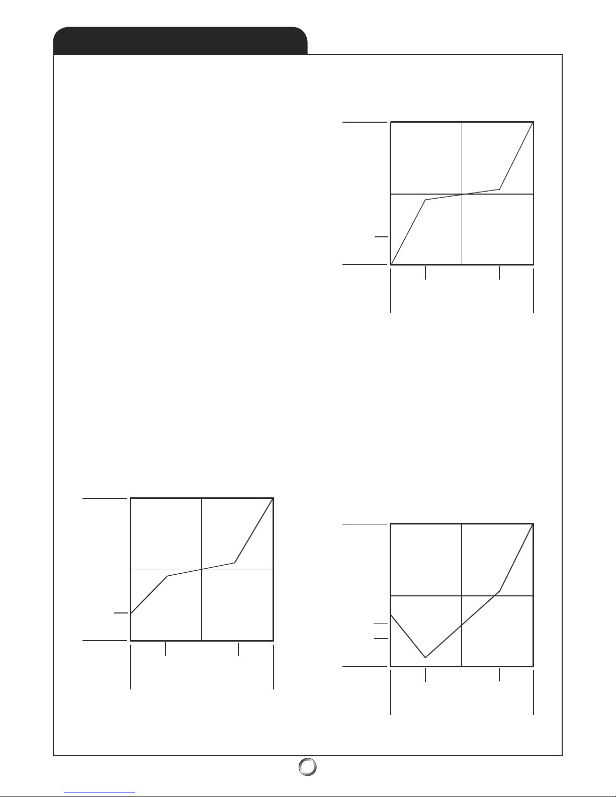
In practice, these Pitch and Throttle Curves often
don’t look like the beautiful straight lines we’ve
used for the manual. Often, to keep main rotor
speed from decaying, or from going too fast, the
pitch throttle points will not be quite as perfect
as those we’ve shown. It’s also worth noting
that for all of the example curves demonstrated,
we’ve assumed you’ve had a radio, which can set
5 points for all the curves. These points are, lowstick, 1/4-stick, mid-stick (or 1/2-stick), 3/4-stick,
and full-stick.
For example, many pilots will have a Normal
Pitch curve (upright orientation) which looks
more like this. (Figure 17)
Stick Position
Pitch
Figure 12
11
o
-3
o
Hover
1/4
3/4
1/2
5.5
o
Normal Pitch- upright orientation
The flattened part of the curve is so collective
pitch control for the helicopter isn’t quite as sensitive. Similarly, the Normal Throttle Curve for an
upright oriented helicopter will look more like
this. (Figure 18)
Stick Position
Pitch
Figure 18
11
o
-3
o
Hover
1/4
3/4
1/2
5.5
o
Normal Throttle Curve - sport
What’s happening here is the throttle decreases
sharply until the stick is at 3/4-stick then flattens
near the hover (mid-stick) position. Again, the
curve stays fairly flattish between the 1/4 and
3/4-stick positions which help keeps throttle
sensitivity good near hover. From the 1/4-stick
position the curve drops steeply again towards
an idle setting.
This is what the Idle Up 1 throttle curve might
look like for an upright, or sport, oriented helicopter. (Figure 19)
Stick Position
Pitch
Figure 19
11
o
-3
o
Hover
1/4
3/4
1/2
5.5
o
Idle Up 1 Throttle Curve - sport
The low point in the curve corresponds to 0
o
0
o
Page 41
41
SET-UP TIPS - CONT.
10.1
of pitch and then the curve climbs as the throttle
is opened to account for the fact the main rotor
blade system is being loaded again as pitch
increases from 0o to -3o of pitch.
The fly in the ointment is the limitation of having
only 5 points on these curves. If you have ever
wondered why top pilots use radio systems like
flagship 9 and 10-channel systems from the likes
of Futaba and JR, the reason is these systems
have more capabilities - chief amongst them,
more points on the curves.
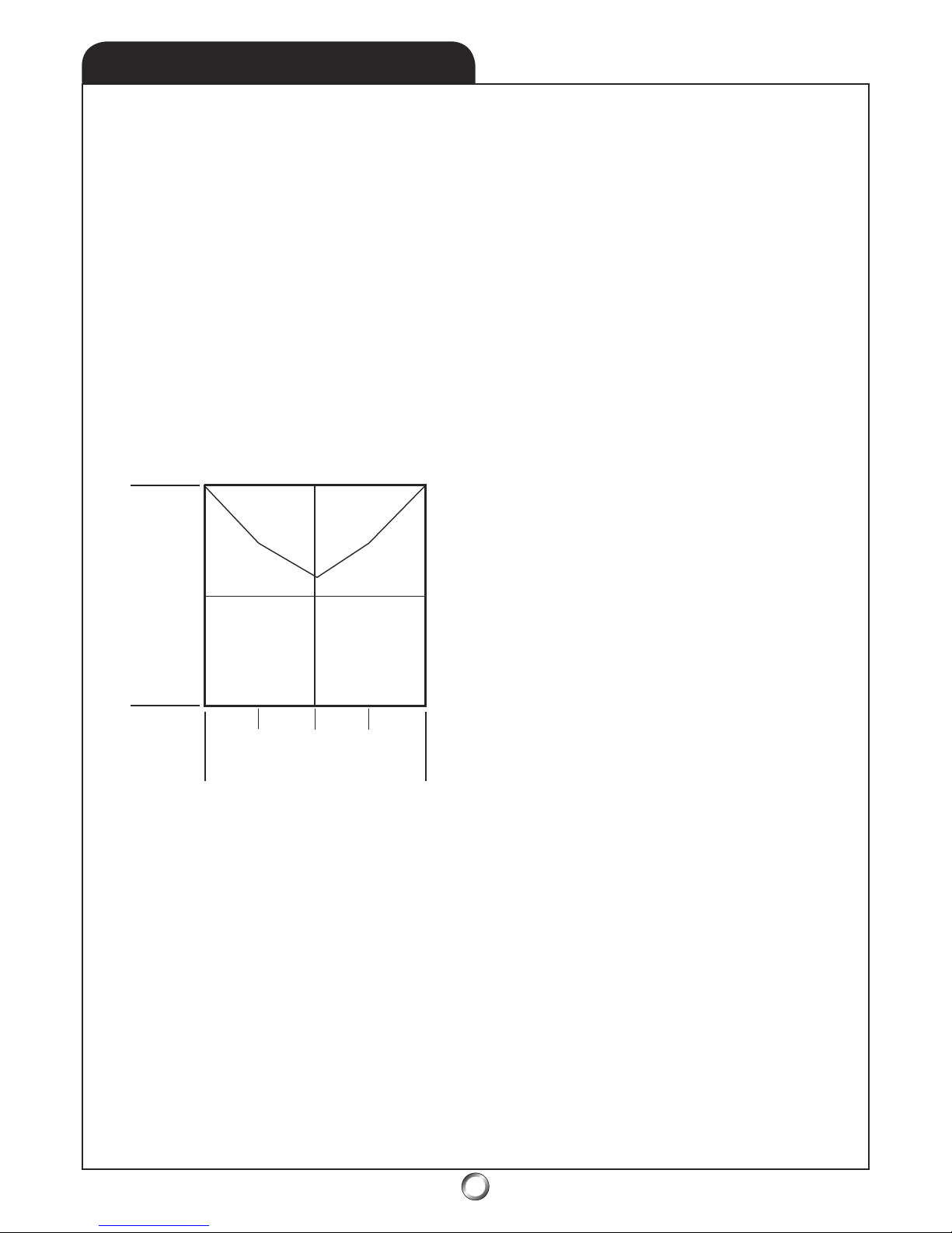
Now let’s look at the Idle Up 1 throttle curve for
a switchless inverted, or extreme performance,
helicopter. (Figure 20)
WOT
Idle
Low
High
Half
Stick Position
V-shape Throttle modified
Figure 20
0
o
5.5
o
-5.5
o
Idle
This throttle curve looks much like the V-shape
throttle curve from Figure 15, but the main difference is the shallowing out of the curve between hover-throttle and 0o pitch. Also note the
throttle doesn’t go fully to idle during 0o pitch as
the pilot is not going to spend much time with
the main rotor unloaded at this point. Instead,
this is actually simply a transition point on the
way to re-loading the rotor disk as pitch goes
negative.
In setting up the throttle curves, you must bear
in mind that while we can measure the pitch
we set up into the main rotor disk (using a pitch
gage), we cannot however, measure the power
settings. Hence, the first thing you set after
establishing the neutral point for all the linkages
(and ensuring the control and servo arms make
perfect 90o angles as they meet) is the desired
pitch for 0o-pitch, hover-pitch, and full-pitch stick
positions. These, of course, are low-stick, 1/2stick, and full-stick for a extreme performance
oriented helicopter. Then, once each of these
stick positions are set, leave the settings alone.
Since we cannot measure power using calipers,
a ruler, or any gage we will establish the proper
throttle position via flight-testing - empirically!
For most pilots, max pitch is the simplest to set
because the carburetor is at WOT (wide open
throttle) position. Remember, depending on the
capabilities of your radio system, you may actually use 95% power at max pitch and keep 5% in
reserve for maneuvers (throttle ATV needs be at
100% - physical WOT). If the engine will not pull
the max pitch you established, then the solution
is to reduce the pitch curve at that point. If the
rotor speed is too high at max pitch, and you
already have all the extra throttle (5%) you want
in your pocket for maneuvers, then increase the
main blade pitch at high stick using pitch ATV.
For the Normal mode, you will use the engine’s
good-idle speed as the setting for low-stick.
Hover power is initially a straight line between
the two other positions and is dialed in when
actually hovering the machine. If when hovering
the rotor speed is too low, then increase the midstick position throttle curve. Conversely, if the
rotor RPMs are too high, reduce engine power at
mid-stick. At this point, as we mentioned earlier,
it is important to again verify the hover throttle
position has the linkage at 90o to the pushrod.
At all costs we desire to keep differential throw
to a minimum - with throttle this will promote a
linear delivery of the power. All adjustments to
the rotor speed are done with throttle curves.
ELECTRONIC SET-UP: Gyroscope
As a rule, piezo crystal gyroscopes have replaced
old-technology mechanical spinning gyros.
These usually feature heading-hold. When in
this mode, turn off the Revolution mix in the
radio (all flight modes using heading-hold will
have REVO turned off). That’s completes initial
set-up - now it’s time to go to the field!
Page 42
42
SET-UP TIPS - CONT.
10.2
FIELD SET-UP: Blade Tracking
You’ve completed an initial set-up on the workbench; now it’s time to make some fine adjustments.
The first thing to do is remove the canopy because this will permit easy access to the linkages. This
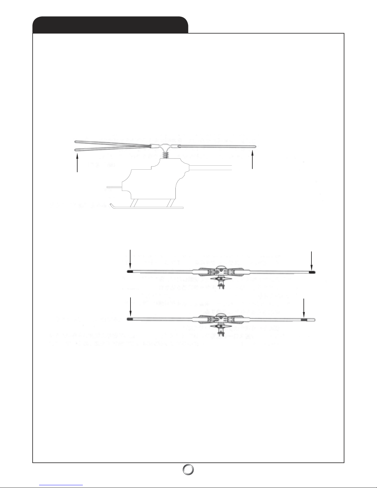
will have a negligible effect on trimming the model, but the prudent modeler may add about 6 oz.
of weight to the radio platform to compensate. If the helicopter does not drift too much, proceed to
blade tracking before trimming the model. If the machine is in need of so much trim that tracking
the blades will be difficult, then perform some trimming first. Hopefully the machine is accurately
built and very little, if any, trim will be needed. The procedure is to lift the machine into a low hover
(skids a few inches off the ground) and verify the blade tracking. It’s great to have an experienced
helicopter pilot’s help at this stage. Apply tracking tape and verify the blades are in track.
Out of track blades
visually identified
through use of the
tracking tape.
Blades in track
Apply Colored
Tr
acking Tape
Different color tape - apply it at
the same position on each blade.
Same color tape - apply it at
different positions on each blade.
* PRO TIP: If main rotor RPM is fine, split the
difference when tracking the blades; lower one
blade and raise the other - but if the rotor RPM is
too high, raise the low blade to match the high
blade and vice versa if the RPMs are too low.
FIELD SET-UP: Trimming & Linkage Adjustment
After tracking the blades, remove the tracking tape, it’s time to make trim adjustments. Lift the
helicopter into a high hover (skids at eye level) so that ground effect doesn’t affect the model. If the
model holds position fairly well, or only needs 1 or 2 clicks, you’re done. If more than this is needed,
make mechanical linkage adjustments to compensate, re-center the trims on the transmitter, and try
again. Verify the neutral position for both the throttle and T/R linkages are correct in the hover.
FIELD SET-UP: Dynamic Blade Balance
Remove balance-weight and re-install canopy. Lift model in high hover. If there are some small
vibrations, try to dynamically balance the main rotor. Pick a blade and add a wrap or two of tracking
tape at the CG of the blade. Lift into a hover and if it’s worse, remove the tape and try adding it to the
other blade. If it’s better but not perfect, add a bit more. This is a trial and error process, which most
pilots don’t bother with, but time spent here will deliver a much smoother performing helicopter.
Page 43
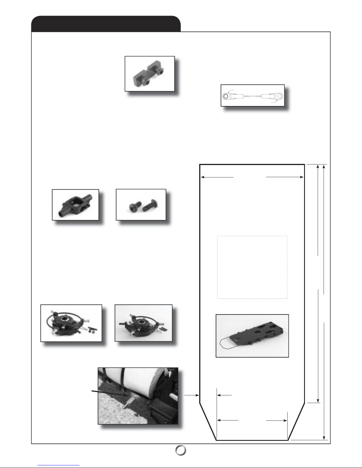
43
10.3 ADDENDUM
A goodie bag of parts, plus some tips to make the Tiger better, are what this addendum is all about.
ADDENDUM v1.9 Parts included: 10) AUD1012 Servo Bosses, 1) AUD0548 Seesaw, and 2) AUD3505 Buttonhead Bolts
6. 3D pilots (who often fl y backward maneuvers) usually
prefer a slightly tail heavy setup. But for learning to hover,
you want the CG (center of gravity) more forward. We offer
AUD0530 (a longer platform), but an inexpensive alternative
is to make a plywood platform-extension from 1/8” aircraft
plywood. Attach it with screws and zip-tie the battery as far
forward as you can thus, shifting the CG further forward.
5. Turns out there is no HD molded on the ball links. Instead,
look closely for a lightly molded ring around the lip on one
side of the links. This ring-side is slightly larger than the other.
Install the link by snapping the ring-side down over the ball.
Ring-side snaps over ball
No ring
2. Want to make your Tiger fl ip and tumble faster, i.e. for
more aggressive 3D fl ight? Included in the goodie bag is a
seesaw with more holes - part number AUD0548. Review
the diagram on page 50 to see where it’s installed. Make
sure you use the two included AUD3505 button head screws
to prevent the seesaw arms binding. If you’re learning to
hover, or enjoy upright fl ight with F3C-style fl ight routines
(like loops and rolls), use the outer hole position (as with
the original seesaw) and the inner hole to tumble and roll
in place (and basically make the Tiger less stable). But be
careful because a boom strike is possible when you’re too
agressive (which is why we offer stiffer PDR0071 dampers).
AUD3505 M3x8
Buttonhead Screw
AUD1012 Servo Boss
1. The new servo bosses AUD1012
included in the goodie bag are
slightly shorter so toss the others.
Then use plastic-type CA glue to
secure them. I prefer that black CA,
IC-2000 (rubber-reinforced Tire
Glue) from Bob Smith Industries.
4. We’ve taken to
using epoxy and micro
ballons (or JB Weld) to
add a reinforcing fi llet
to the bosses which
hold the canopy posts
on the radio platform
and frames. They seem
to break pretty easy so
this saves a few bucks!
2-1/4”
1-1/2”
5-9/16”
6-1/4”
Use this template
for making a radio
platform extension
out of 1/8” aircraft
plywood as an aid
for moving the CG
(center of gravity)
further forward.
3/8”
3. We forgot to mention in the manual what to do with two little
black spacers (4mm dia x 2.8mm), the F3C swashball extensions.
Install them under the short balls on the upper ring of the swashplate per the Pro Tip in section 4.1 - these are for sport aerobatic
use. For 3D, buy the PDR0069 3D Swashball Kit because it’s
more of the same (but 4.25mm instead of 2.8mm high). Novices
shouldn’t install any extensions! Swashball extensions like the
F3C and the PDR0069 option are another tool in the arsenal of
the pilot seeking to extend the performance envelope via tuning.
www.audacitymodels.com
AUD0548 Seesaw
PDR0069 3D Swashball Kit Seesaw
F3C Swashball extension
Extend radio tray
with 1/8” plywood
Check that this
prints full size!
Template:
Page 44
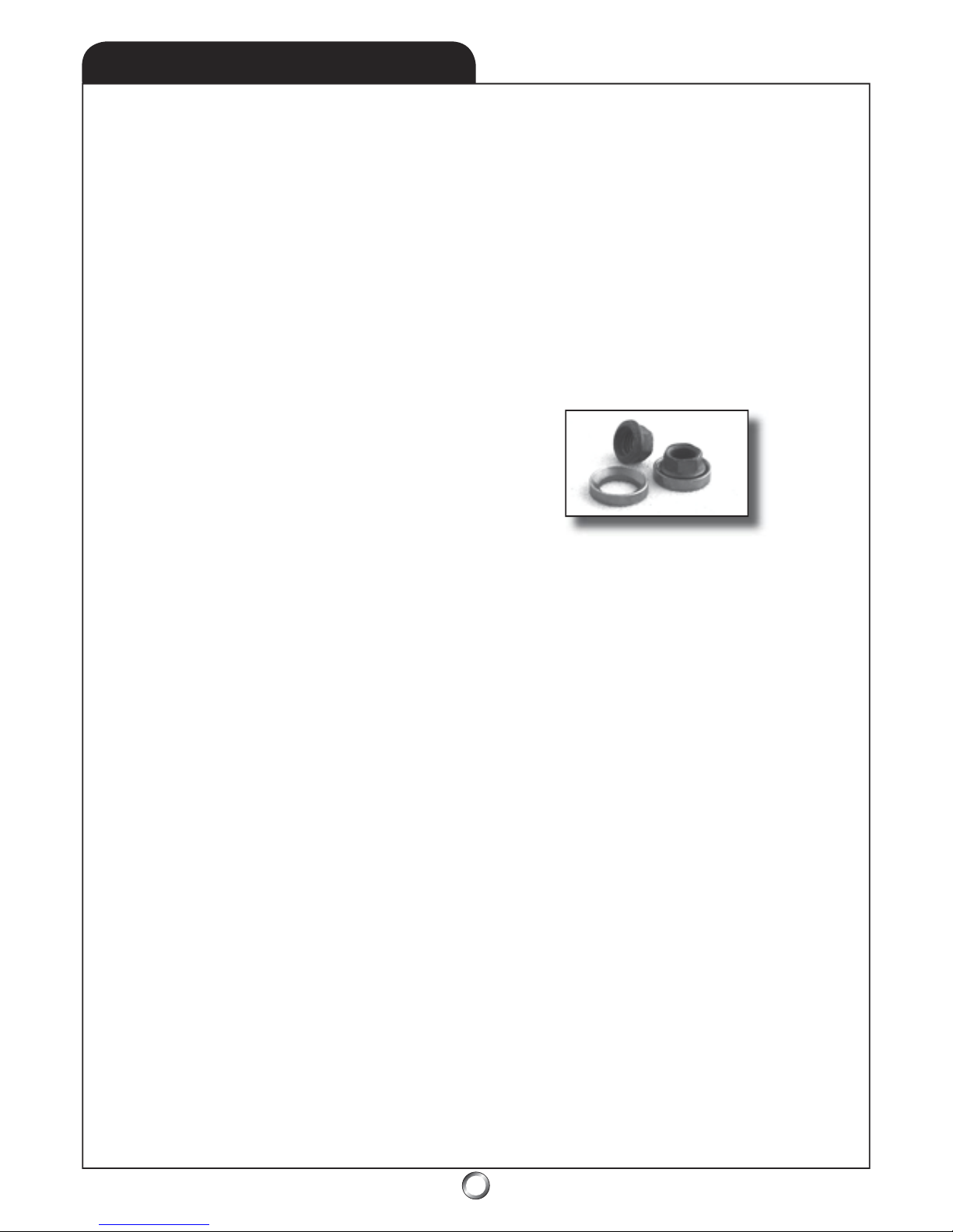
44
www.audacitymodels.com
7. Servo arms are an important part of setting up your
Tiger. There’s a mistake in the manual on pages 26, 27,
and 31 where we suggest using 20 mm long servo arms for
the three swashplate servos. In fact, the forwardmost servo
should operate through a 23 mm long servo arm instead of
a 20 mm servo arm. The reason is AUD0027 Elevator Arm
reduces throw by 15% to clear the start shaft. Mechanically
compensate by using a servo arm that’s 15% longer than
the arms used on the two aft servos. Hence, a 23mm long
servo arm is pefect if you use 20 mm arms for those because
20 mm x 15% = 3 mm, or 20 mm x 1.15 = 23 mm thereby
resolving the issue quite elegantly. We’re partial to the
HD servo arms manufactured by Du-Bro, their parts #670
for Futaba, #671 for JR, and #672 for Hitec brand servos.
Also, instead of a 12.5 mm servo arm for the tail rotor servo
we’re using a longer arm (15-18 mm) instead.
8. Under hard use, thread locker securing the pinion gear
of the AUD0526 Clutch Bell Assembly to the AUD3077
10x19x7 bearing can work its way loose. If you’re hearing
a ringing sound (kind of like a bell) the pinion may have
worked its way loose. The fi x is to clean the old thread
locker off with acetone and re-assemble with thick CA or
JB Weld. The real trick to making it bulletproof though is
to use thick CA or JB Weld on it while it’s new! Remove
the front landing gear bolts and drop the engine. Some have
reported they’re placing a pair of needle-nose pliers on top
of the clutch bell and giving it a tap with a hammer to pop
it loose, but because some have also damaged the frames
where it holds the bearing, we think it’s best to just split the
frame! We get away with just removing the frame bolts forward of the Tail Drive Pinion Assembly and fl ex the frames
open (make sure you remove the M3x12mm that’s inside the
curve of the fan shroud too). In fact, you may not even have
to remove servos because there’s usually enough slack in
the wiring. Next, clean the thread locker off with acetone or
laquer thinner (the thread locker dissolves very easily) and
use either thick CA or JB Weld to re-bond the pinion into
the bearing (instead of thread locker as detailed in step 1.1).
However, as with thread locker, be especially careful not to
get CA into the bearing because it’ll lock it up tighter than a
tick on a hound dog . . . you’ve been warned!
9. Disassemble the thrust bearings located inside the main
rotor blade grips and grease them. This will maximize
service life. We have used many types of grease and don’t
think which kind matters in the least regardless of whether
it’s wheel bearing grease, white lithium grease, or whatever
you have on hand! This is an easy job, but please refer
to the drawing for proper thrust bearing re-assembly as
detailed in the manual’s exploded views (refer to 11.3 Main
Rotor Head & Seesaw). There’s really only one thing that
might bite you on the rear. There are two grooved washers
in each thrust bearing pack, and getting them backwards
will make blade tracking inconsistent since these washers
differ slightly in the ID. Just make sure the grooved washer
with the larger ID is installed on the hub-side while the one
with the smaller ID is installed toward the nut-side. Finally,
while you’re at it, put just a smear of grease on the dampers
(where the spindle shaft rides) so that they don’t bind.
10. There’s a mistake in the manual affecting steps 3.3 and
3.5 because these bolts are reversed. The correct bolts to
mount the engine to the engine mount (as detailed in step 3.3)
are the 3x12 mm shown in step 3.5. The longer 3x15 mm
bolts (from step 3.3) should instead be used in step 3.5 for
securing the engine mount (with aluminum cap washers) to
the side frames.
11. Turns out the note about not using thread locker on the
crankshaft nut (step 3.3) isn’t the last word. We now think
it’s best to use blue thread locker to secure the nut. Also, if
you dial-indicate the AUD0037 Clutch Hub (to minimize
vibration), then PDR0090 Equalizing Nut (used in the wings
of Boeing jets) is the Cat’s Meow to keep the runout from
changing as you tighten the engine nut because its ball-andsocket design prevents it from pulling the hub off center!
12. Complaints of the tail boom working loose have two
usual sources - using a screwdriver-handle type Allen to
tighten the four M3x38 mm aft frame bolts vs. an L-shaped
or T-handle Allen-wrench (to really tighten the suckers), or
forgetting to tighten the M3x4 set screws located on each
side frame (as detailed in step 5.7). Here are a couple of
tips; fi rst, while some advocate a wrap of electrical tape on
the boom before plugging it in, we DO NOT think this is
necessary. If you feel you must, you can tighten the fi t this
way instead; remove the four aft frame bolts and pass a thin
Zona-type saw blade between the crack formed where they
join - this removes a few thousandths of material. better
still, if the frames haven’t been assembled yet (or you’re
willing to disassemble them), lightly pass a sanding block
on the aft part of the frames before joining. Second, substitute a couple of M3x10 Allen Head bolts for the supplied
set screws so that you can use the same 2.5 mm Allen driver
everywhere - these don’t round out as easily! Also, because
it’s not unusual for these safety set screws to actually punch
through the boom (which certainly keeps it from working
loose), we fi rst fl y the heli a time or two (because the belt
stretches a little) and then we secure these safety set screws!
13. On 9.0 Set Up Tips, there’s a mistake as the two aft
servos are reversed. The starboard (right) aft servo should
actually be plugged into channel 1 and the port (left) aft
servo should instead be plugged into channel 6. The same
issue pops up with with different brands of equipment as
per step 9.3 where channel numbers are refered to as Aux
1, ELEV, and AILE - please refer to your radio equipment’s
manual for specifi cs.
14. AH-xxxx and PRO-xxxx part numbers are superceded
by AUD-xxxx and PDR-xxxx - numbers don’t change.
10.4 ADDENDUM
PDR0090 Equalizing Nut
Page 45
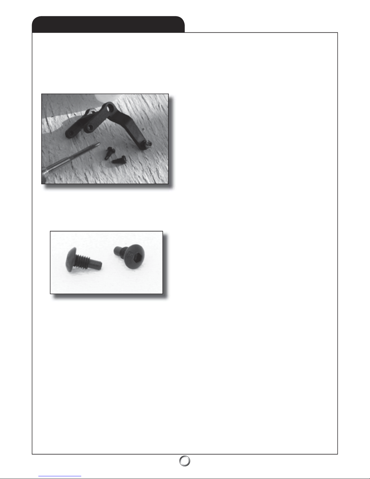
45
15. We’ve been fortunate that some of the best 3D pilots
in the world have chosen to use a Tiger 50 as a “beater”
for practicing the presentation of their 3D routines. As a
direct consequence (because they fl y their Tiger 50 harder
than mere mortals) their ideas may lead to inprovements for
the rest of us. The tip that follows is one that we call the
“Henry Caldwell Tail Pitch Control Lever Modifi cation”.
This mod involves AUD0010 Tail Pitch Control Lever, and
requires an X-Acto with a #11 blade, a drill, the appropriate
drill bit and 3 mm tap, as well as PDR-0079 3D Guide Pins.
These can increase the service life of the tail pitch control
lever under grueling abuse imposed by aggressive 3D pilots.
PDR0079 3D Guide Pins
Step 1 - Remove AUD0010 Tail Pitch Control Lever from
the Tail Gear Case Assembly by using a drift to drive out the
tail lever bushing - a makeshift drift can be an Allen driver.
Step 2 - Use the X-Acto to slice off the two plastic nubs
which fi t the grooves to drive AUD0014 Tail Slide Ring.
Step 3 - Drill and tap for 3 mm. This is easy because there
is a round molded recess directly opposite (on each side)
from where the pins were. Just be careful to center the drill
bit beforehand and go for it. If you screw up, it’s not the
end of the World, a replacement AUD0010 is inexpensive.
Step 4 - Use a drop of plastic CA glue as a thread locker and
an Allen driver, screw in the PDR0079 3D Guide Pins.
Step 5 - That’s it! Reinstall the Tail Pitch Control Lever.
Special thanks to: Henry Caldwell for coming up with the
idea, Marcus Kim for letting his Tiger 50 be the guinea pig,
Eric Reinhart for the tools to accomplish this, and most
especially Lee O’Dell for generously donating the guide pins
off his Freya for the experiment. The idea was prototyped
at Blacksheep, SC over the 2005 Independence Day Holiday
and a mere 5 weeks later we had approved the drawings,
manufactured the guide pins and were shipping! This little
modifi cation can really help maintain precision longer!
16. Assembling the AUD2003 Ball Link Ends to the
AUD1521 Tail Rotor Pushrod becomes a lot easier if you
fi rst use a 5/64 drill bit (.078”) and drill out the slightly
undersized holes before threading them onto the pushrod.
17. We’ve had reports of blades occasionally going out of
track and have learned it’s related to excessive play in one
of the Seesaw Arms. Check for excess play before fl ying
your model because the resulting fl utter can easily be strong
enough to lead to a Spindle Shaft bending. Fortunately,
the shaft is a sacrifi cial part and hence, is cheap and easy to
replace. The cause is usually either the screw securing the
Seesaw Arm on the shaft has backed out slightly, or there’s a
ganging of tolerances which has resulted in a loose fi t on one
of the arms. Checking for either condition is actually pretty
easy. First, grasp the Seesaw Arm between your thumb and
forefi nger and give it a side-to-side wiggle. Next, rotate the
head around and check the other Seesaw Arm the same way.
If you’ve experienced blades going out of track, then dollars
to donuts there’s more play in one Seesaw Arm vs. the other!
You may be asking yourself, “What’s ganging of tolerances?”
Simply this . . . it’s surely no surprise that two bearings with
the same part number can actually vary slightly in size, right?
I.e. measure them using instruments of suffi cient precision
and you’ll almost always discover that one can be slightly
thinner than the other. Similarly, the ID and the OD can vary
slightly as well. The same holds true for the shaft - such
that it might be slightly longer than others in the same parts
bin. Ditto with the seesaw arm itself, but nonetheless, these
differences are within the +/- tolerances of the design. Then
during assembly; thinner bearings, maybe a seesaw arm with
a thinner ring gap, or perhaps a longer shaft, when assembled
result in slightly too much play in one of the seesaw arms. It
doesn’t happen often but occasionally parts (each in proper
tolerance) when combined may result in an assembly that’s
out of tolerance - in this case too lose!
First, just try tightening the bolt. Be careful though since
this bolt threads into the plastic seesaw. Fortunately, if it’s
stripped, all’s not lost since plastic-type CA used as thread
locker will have you back in business because you can pretty
much restore the threads using it. If the damage is too bad,
happily, seesaws are inexpensive so it’s not that big a deal.
If it’s not loose, then back the bolt out and look to see if the
shaft itself (the one the bearings ride on) isn’t just a hair too
long (you’ll see it sticking out past the inner race of the outer
bearing of the seesaw arm - it’s pretty easy to discern). If this
is the case, then fi le a few thousanths (or however much is
needed to make for a perfect fi t) off the end of the shaft.
That’s how you remove the extra play and the process is
called “blue printing”. Top pilots blue print every assembly
of a machine. Most of us aren’t top pilots, but blue printing
an assembly is a simple, easy, and free modifi cation. Best
of all, it may result in a tangibly better handling helicopter
plus it’s fun to do - after all, it’s called modeling for a reason!
While you’re at it, check the mixing arms for excess play and
blue print them to perfection also!
10.5 ADDENDUM
www.audacitymodels.com
Page 46
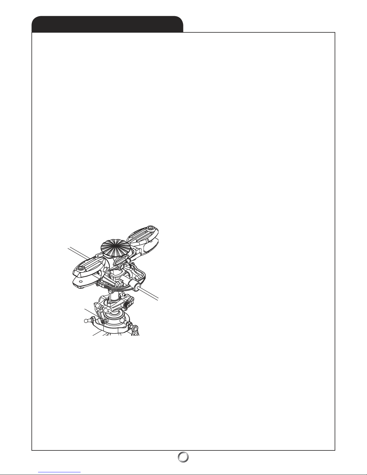
46
10.6 ADDENDUM
www.audacitymodels.com
18. A member of the Audacious Crew came up with an idea
for making the Tiger 50 fly better and it really works! It’s
called the “Kevin Garver Positive Delta Modification” and
it makes for a real improvement in the flying chracteristics
of the Tiger 50 . . . and it doesn’t cost a thin dime! His idea
led to this recommendation for flipping the main rotor blade
grips over so the main rotor blades are controlled from the
leading edge vs. from the trailing edge (resulting in positive
delta vs. negative delta). The ensuing aerodynamic forces
work to provide more precise collective and cyclic control
and best of all, it’s both easy to accomplish . . . and free!
The goal is to invert, or mirror image, everything north of the
Swashplate. These include the Mixing Base/Mixing Arms,
the Seesaw/Seesaw Arms, and the Control Lever Assembly
as well as the Main Blade Grips. It’s easy, here’s how . . .
Step 1 - DISASSEMBLY - use ball link pliers and remove
the links (to include the Washout Link) leading from the
Swashplate up to the Main Blade Grips. Then remove a
Flybar Paddle, loosen the set screws on the Control Lever
Assembly, and slide the Flybar out as well. Take the Seesaw
Arms off the Seesaw followed by the two screws holding the
Seesaw onto the aluminum Center Hub Assembly to remove
the Seesaw itself. Next, remove the Jesus Bolt and lift the
Head Assembly off the Main Shaft. Finally, lift the Washout
Base/Mixing Arms off the Main Shaft.
Step 2 - MODIFICATION - For the full collective pitch
range (-11/+11 degrees) you must cut about 1/8” from the
bottom of the Washout Base (if you’re not doing full inverted
climb outs, don’t bother because you get about -8 degrees
without modifying the mixing base - enough for a moderate
inverted climb out). I use a Dremel tool with a cutoff disk
but because the inner liner of the Washout Base is made of
steel it’s helpful to occasionally dip the Mixing Base in a
bowl of water to keep the steel sleeve from getting too hot
and melting the plastic. Alternatively, get someone to hold
a wet sponge above the Washout Base and dribble water on
the job for cooling (as you cut it). Also, use the Dremel and
cutoff disk to trim enough (about 1/8”) off the rotor blade
bolts to keep them from gouging your palm when you use
your hand as a rotor blade brake - you’ve been warned!
Step 3 - RE-ASSEMBLY - Refer to the drawing. First
replace the Seesaw - remember to invert it. Reinstall the
Seesaw Arms, then slip the Control Lever Assembly in place
and ease the Flybar through it and the Seesaw. This has been
done correctly when the Set Screws which secure the Flybar
are tightened from the bottom vs. from the top. Now replace
the second Flybar Paddle and re-align everything. Then,
re-install the Mixing Arms onto the Washout Base and slip
this over the Main Shaft - but ensure the side which you cut
off faces upwards and the Washout Arms are reversed. Snap
the Washout Links onto the long balls on the upper star of
the Swashplate. Next, re-install the head assembly and the
Jesus Bolt - and please remember to tighten it securely. Trust
me when I say it’s a sick feeling to watch the rotor disk go
sailing off pretty as you please while the Tiger 50 imitates a
costly Lawn Dart - and don’t ask me how I know, but you’ve
been warned - sob! Now remove one of the M4 Nylon Lock
Nuts from the Spindle Shaft and slide the grips apart enough
to permit you to rotate them 180 degrees (flip them over in
other words) and re-tighten the M4 Nylon Lock Nut. Finally,
re-install the linkage rods.
Step 4 - PROGRAMMING - Next, let’s reverse the pitch
direction - do this in the Swashplate Menu of the transmitter.
It’s where you have values for Elevator, Aileron, and Pitch.
All you do is reverse the value for Pitch. For example, if the
value is +55, change it to -55 . . . or from -60 to +60 and the
Swashplate will now move down for positive pitch instead of
moving upward - and vice versa! You’re done!
This is the new “official” way we recommend assembly of
the main blade grip control. The only downside to this little
modification is the set screws securing the flybar are reached
from below and similarly, the bolts securing the main rotor
blades install from the bottom as well - a small price to pay!
Reversed Main Blade Grips
19. Installing the 3D paddles is simplicity itself, but you
must ensure they are properly installed. Make sure none of
the threads on the flybar are exposed, i.e. that they’re fully
covered by the body of the paddles (or the flybar can break
where the threads start). Just make a mark 1” from the end
of the flybar, then screw the paddles on until the inside edge
of the paddle meets the mark. Also, some 3D-pilots like
to experiment and try to improve the flight characteristics
when using these paddles - it’s easy. First, slice 1/8” off the
leading edge. Next, using a sanding block, simply re-profile
the edge back to an aerodynamic shape. Finally, check to
ensure they still weigh the same - that’s it!
20. The inevitable will occur. Yes, despite your best efforts
(perhaps even due to your best efforts), the time will come
when your Tiger 50 meets terra firma at a rapid rate and
what results is a smokin’ hole in the ground! Inevitably this
greatly amuses the peanut gallery (while you’ll be shaking
your head in dismay). If (when the momentous occasion
occurs), the damage includes the AUD0013 Tail Pitch Plate
(this piece supports the two AUD0012 Tail Pitch Links and
threads onto the AUD1005 Tail Slide Ring Sleeve), then remember this - the assembly doesn’t use the usual right-hand
threads . . . it uses left-hand threads - you’ve been warned!
Page 47

47
10.7 ADDENDUM
Check for most recent update at:
www.audacitymodels.com
- John Beech, GM (and janitor), December 2005
This addendum is how I’d have written the
manual had I known then what I know now!
21. I’ve been asked a few times about lubing bearings and
other points of friction on the Tiger 50. First, remember
the goal of lubrication is to reduce friction and the resulting
accelerated wear due to the rubbing together of parts. We
do this with lubricant. This, naturally enough, raises the
question of what to use? While I happen to think that even
spitting on it is better than nothing, I also suspect some may
want a recommendation other than that. I don’t care for
WD-40 for this application (though it’s better than nothing
also), and 3-in-1 (or any light sewing machine oil) is decent
but attracts dirt - which is bad! I prefer a synthetic high tech
lube like Tri-Flow with Teflon. This brings us to where and
how often the lubrication should be applied.
To lube the little bearings contained within the tail rotor
blade grips, I place a few drops on the hub side of each tail
rotor grip (right on the shaft itself, actually). Then rotational
forces will ensure the oil flows through the bearings! For
good measure, I also lube where the tail slide ring sleeve
rides on the tail output shaft. While I’m at it, I also put a
couple of drops right where the swashplate rides on the
main shaft. Ditto for the washout base also. That’s because
these both ride up and down on the main shaft with pitch
changes. I also put a few drops at the main rotor blade grips
(the same as for the tail rotor grips, i.e. right on the shaft
and let rotation distribute the oil throughout the bearing).
Finally, I place a drop or two at each main shaft bearing, the
start shaft bearings, and the tail output shaft beaings also. I
lube these places before flying begins for the day.
However, with respect to lubing the bearings in the main
rotor blade grips, I rather suspect this may also be serving
to wash some of the grease out of the thrust bearings. But
unfortunately, there doesn’t seem to be an easy answer for
this issue since oil seems best for ball bearings and grease
for thrust bearings. Hence, I re-lube the thrust bearings
every time the spindle shaft is replaced, or after every case
or two of fuel - presuming I have’t had the head/grips apart
due to a crash repair!
Are you’re wondering how well rotational forces work?
Following the first flight after lubing the bearings in the
grips using this method, I have to wipe excess lube off the
roots of the main rotor blades as well as the tail rotor blades
(to remove the lube that was slung through the bearings).
Anyway, that’s how I do it . . . and it’s not just for my Tiger,
but for all my helicopters! By the way, one reason I lube so
frequently is because I also happen to be meticulous about
keeping my helicopters clean. To make this job easier, I
spray them down with denatured alcohol once I get back to
the workshop. Next, I use a jet of high pressure air (from
my air compressor) to blast things nice and clean! Finally, I
touch up by wiping with a diaper (these work great for rags)
whilst checking for anything wearing or broken (which may
have escaped my attention at the field). Since it seems to
me I may very well be washing away some lube along with
any oil and dirt on the model, I figure the best thing to do is
just re-lube these points before the start of flying each day.
22. Four large (about an inch in diameter) black plastic
washers (included with the model) are shims for the main
rotor blades. That’s because the main rotor blade grips are
designed to accept either the stock 12 mm thick blade root,
or accessory 14 mm thick blade roots. The shim washers
are designed to be fit on each side of each main rotor blade
(they’re only 1 mm thick) before being inserted into the
grips and while they’re something of a tight fit, they do fit!
Some folks advocate permanently gluing them to the blade
roots using CA-type glue. While there’s nothing wrong with
this, I’d recommend using a tiny drop of CA instead so you
can salvage them in the event you break the blades. Then
all you’ll have to do is slip the a #11 X-Acto blade under the
edge of the washer and pop it loose. Lynn says I shouldn’t
be so cheap . . . I just think I’m being thrifty!
23. We’ve had some issues with the threads in the body of
the AUD0001 Hex Start Adapter not being fully cut. Before
final assembly using thread locker, make sure the threads
are actually cleanly cut by first running the set screw all the
way into the body until you see it penetrate into the center
(which is how it secures the adapter to the flat of the start
shaft). If the threads aren’t clean, then just run a tap through
it to finish cleaning them up. Finally, remember to use
plenty of thread locker so the hex start adapter doesn’t come
loose . . . which as we all know, Murphy’s Law dictates will
always happens at the field while you’re showing off your
new pride and joy to the peanut gallery!
Page 48

48
10.8 ADDENDUM
Page 49
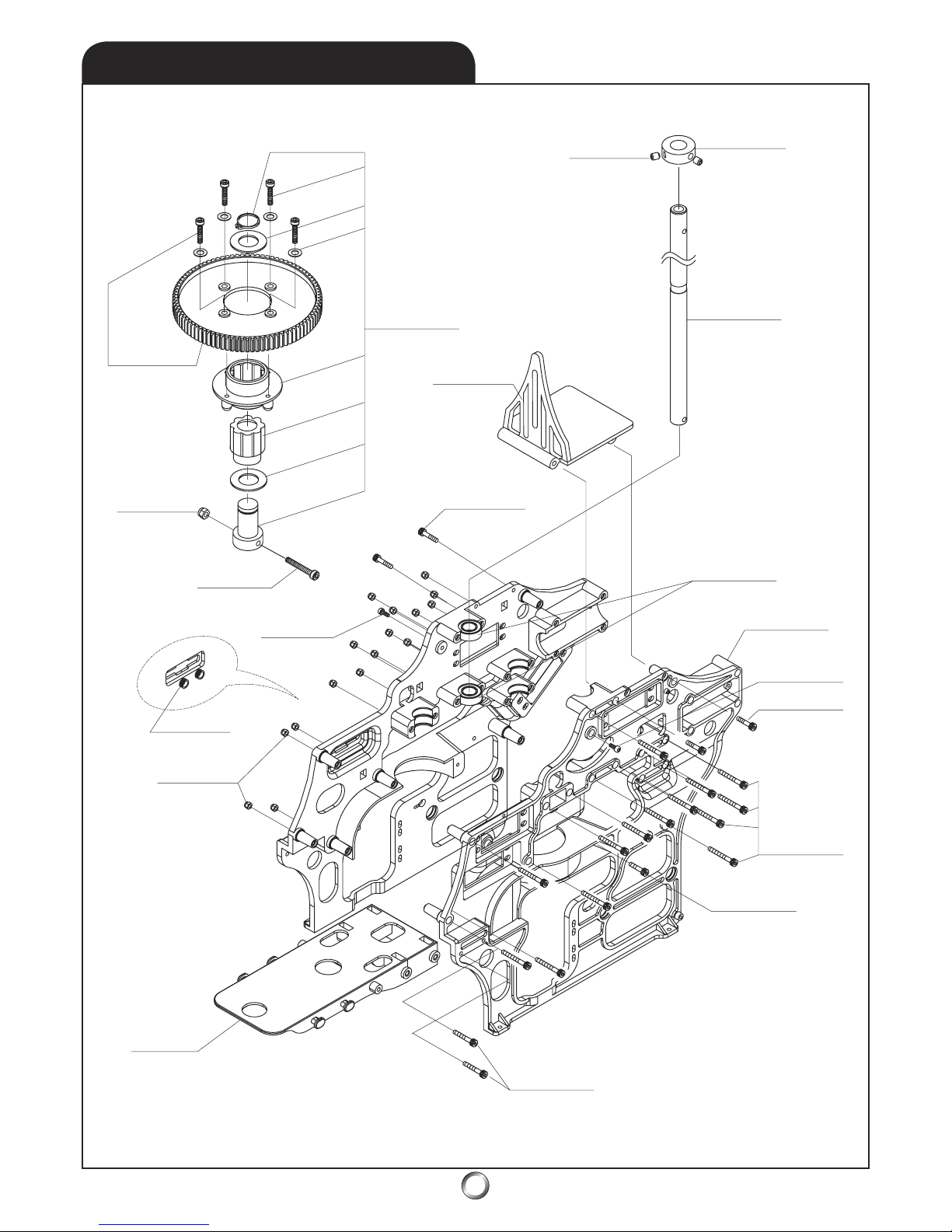
49
MAIN GEAR & FRAMES
11.0
AH-3065
AH-0031
AH-0032
AH-0052
AH-3021
AH-3010
AH-3005
AH-1003
AH-3021
AH-0030
AH-300
6
AH-301
2
AH-3006
AH-300
5
AH-002
9
AH-307
7
AH-300
6
AH-000
3
AH-303
6
AH-1013
AH-3007
Page 50
50
PARTS LIST
11.0
PART # DESCRIPTION QTY REMARKS
AH-0003 MAIN MAST
MAIN MAST 1
AH-0029 MAIN FRAME
MAIN FRAME (R & L) 2
AH-0030 RADIO PLATFORM ASSEMBLY
RADIO PLATFORM 1
M3x10 SOCKET HEAD BOLT 4
AH-0031 MAIN GEAR ASSEMBLY
MAIN GEAR 89T 1
M3x10 SOCKET HEAD BOLT 4
M3 FLAT WASHER 4
AH-0032 AUTO ROTATION ASSEMBLY
M11 SNAP RING 1
1 WAY BEARING HOUSING 1
1 WAY BEARING (1WC1216) 1
AUTO-ROTATION SPACER 2
1 WAY BEARING SHAFT 1
AH-0052 GYROSCOPE PLATFORM ASSEMBLY
GYROSCOPE PLATFORM 1
M3x10 SOCKET HEAD BOLT 4
AH-1003 SWITCH RUBBER
ROUND RUBBER GROMMET 2
AH-1013 MAST STOPPER ASSEMBLY
MAST STOPPER 1
M4x4 SET SCREW 3
All screws, washers, nuts, and bearings on 11.7 Hardware List
Page 51
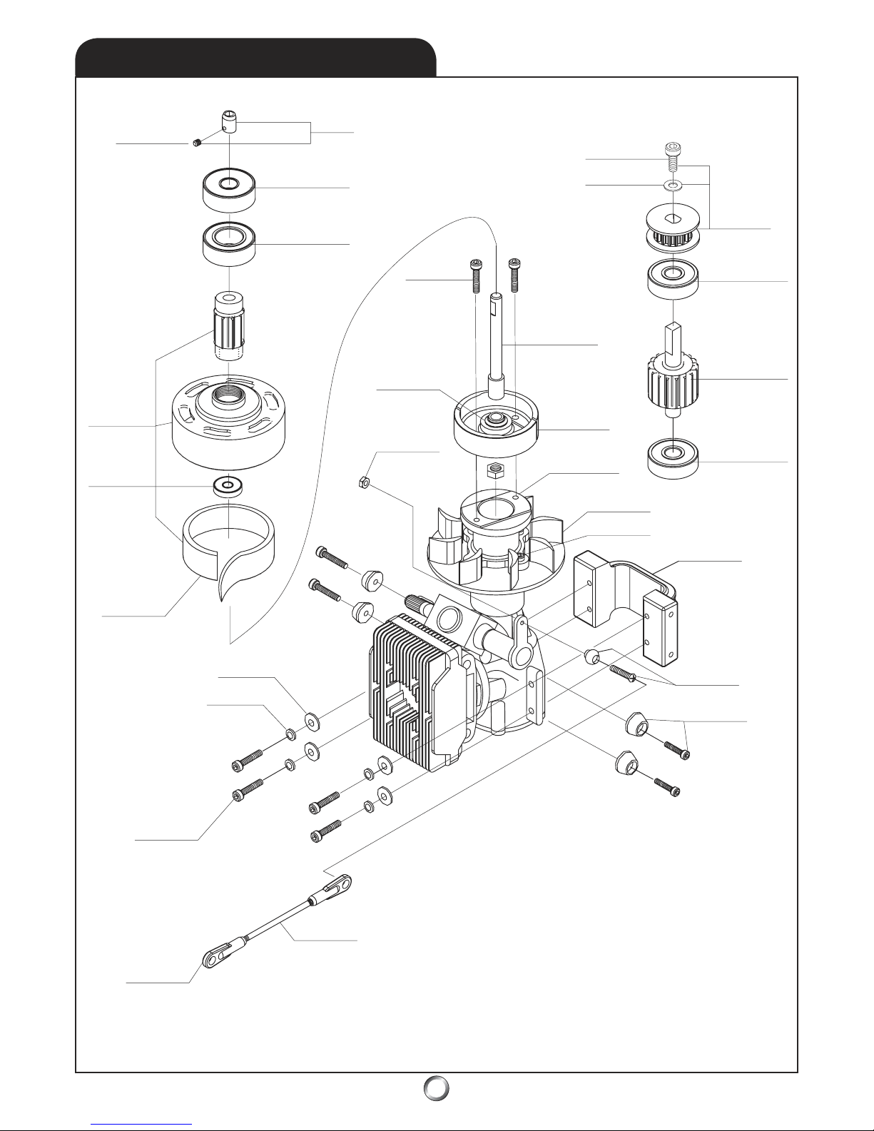
51
11.1
AH-3036
AH-0001
AH-3080
AH-3077
A
H-0526
AH-3075
AH-1510
AH-3062
AH-3063
AH-3009
AH-2003
AH-3055
AH-101
4
AH-200
2
AH-053
4
AH-300
5
AH-003
6
AH-003
7
AH-053
8
AH-3023
AH-3072
AH-003
5
AH-300
5
AH-308
1
AH-1011
AH-308
1
AH-050
2
AH-306
2
AH-300
4
* NOTE: Engine Not Included
ENGINE & BELT DRIVE
ENGINE & BELT DRIVE
Page 52
52
11.1
PARTS LIST
PART # DESCRIPTION QTY REMARKS
AH-0001 HEX START ADAPTER ASSEMBLY
HEX START ADAPTER 1
M4x04 SET SCREW 1
AH-0035 START SHAFT
START SHAFT 1
AH-0036 COOLING FAN
COOLING FAN 1
AH-0037 CLUTCH HUB
CLUTCH HUB 1
AH-0502 FRONT TAIL BELT PULLEY ASSEMBLY
FRONT TAIL BELT PULLEY 1
M3x06 SOCKET HEAD BOLT 1
M3 FLAT WASHER 1
AH-0526 CLUTCH BELL ASSEMBLY
CLUTCH BELL 1
10T PINION GEAR 1:89 RATIO 1
AH-0534 ENGINE MOUNT
ENGINE MOUNT 50 1
AH-0538 CLUTCH ASSEMBLY
CLUTCH SHOE 1
M3x08 SOCKET HEAD BOLT 2
AH-1011 TAIL DRIVE PINION GEAR
TAIL DRIVE PINION GEAR 1
AH-1014 CAP BOLT HOLDER ASSEMBLY
CAP BOLT HOLDER 4
M3x12 SOCKET HEAD BOLT 4
AH-1510 CLUTCH LINING
CLUTCH LINING 1
All screws, washers, nuts, and bearings on 11.7 Hardware List
Page 53
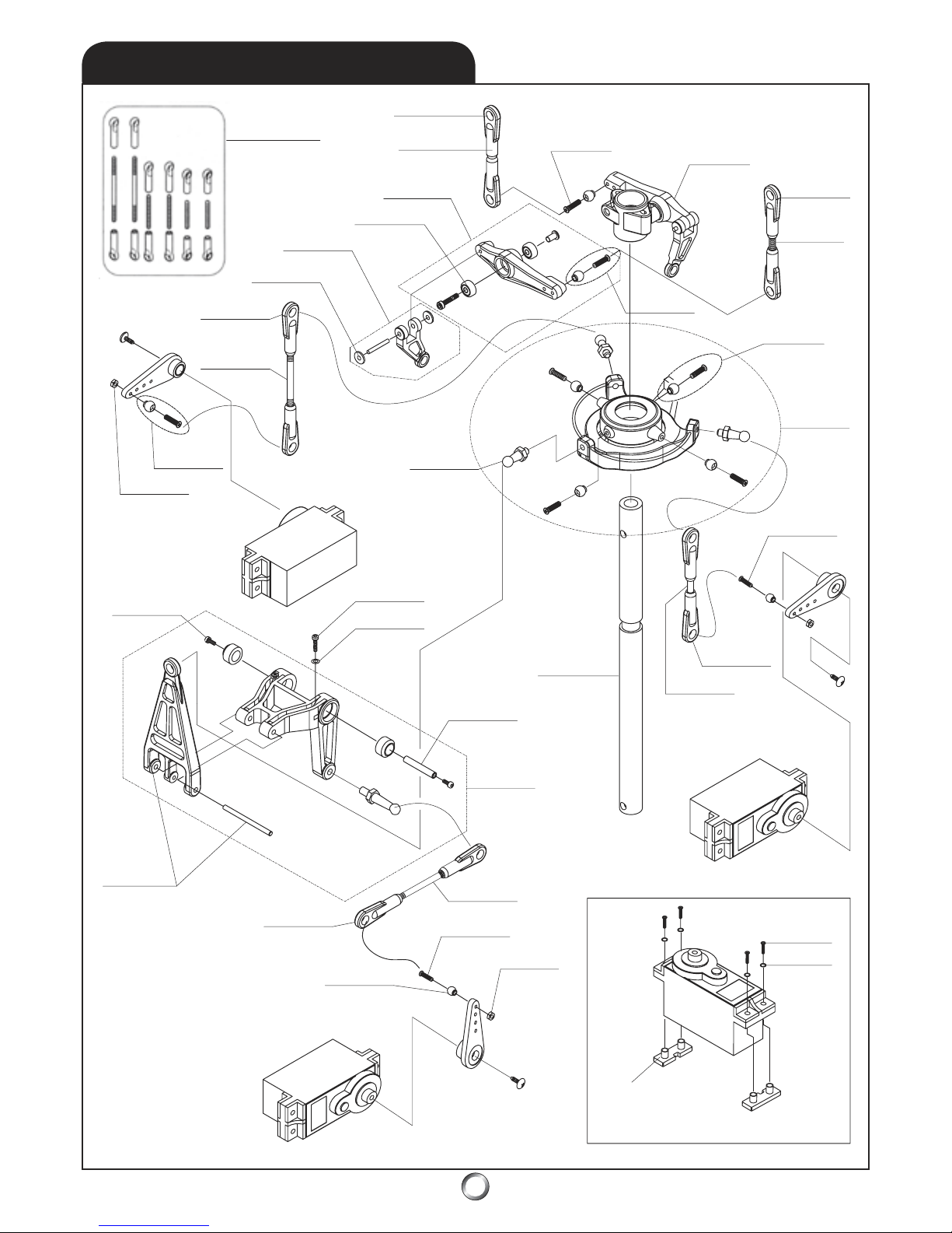
53
11.2
AH-2003
AH-3050
AH-1015
AH-3071
AH-1001
AH-3064
AH-2003
AH-3053
AH-2003
AH-3023
AH-3005
AH-0006
AH-2003
AH-2003
AH-302
3
AH-3040
AH-305
5
AH-002
7
AH-100
2
AH-000
3
AH-3060
AH-3002
AH-1007
AH-304
0
AH-000
4
AH-200
2
AH-200
3
AH-305
0
AH-200
2
AH-003
9
AH-304
0
AH-200
3
AH-305
2
AH-304
4
AH-3061
AH-101
2
SERVO MOUNT
* NOTE: Servos Not Included
AH-0025
CCPM, SWASHPLATE, & MIXER
Page 54
54
11.2
PARTS LIST
PART # DESCRIPTION QTY REMARKS
AH-0003 MAIN MAST
MAIN MAST 1
AH-0004 WASHOUT ASSEMBLY
WASHOUT BASE 1
AH-0006 SWASHPLATE ARM LINK ASSEMBLY
SWASHPLATE ARM LINK 1
ELEVATOR ARM PIN 1
AH-0025 LINKAGE SET
M2.3x CONTROL ROD 2
M2.3x CONTROL ROD 2
M2.3x CONTROL ROD 2
-L- BALL LINK 8
-S- BALL LINK 4
AH-0027 ELEVATOR ARM ASSEMBLY
SWASHPLATE ARM 1
ELEVATOR ARM 1
BALL ARM (14.5mm) 1
M2 FLAT WASHER 2
M2X10 SOCKET HEAD BOLT 2
ELEVATOR ARM PIN 1
ELEVATOR ARM BUSHING 2
M2 NUT 2
M3x8 SOCKET HEAD BOLT 2
AH-0039
120
O
SWASHPLATE ASSEMBLY
SWASHPLATE 1
BALL ARM 3
JOINT BALL 4
M2x10 TAPPING SCREW 2
M2x13 TAPPING SCREW 2
AH-1001 WASHOUT LINK ASSEMBLY
WASHOUT LINK 2
PIN 2 X 14 2
PERMANENT PUSH NUT 4
AH-1002 ARM SHAFT
ARM SHAFT 1
AH-1007 BALL ARM
BALL ARM 1
AH-1012 SERVO MOUNT BOSS SET
SERVO BOSS PLATE 10
AH-1015 WASHOUT ARM SET
WASHOUT ARM 2
WASHOUT ARM SHAFT 2
BEARING 4
M3x15 SOCKET HEAD BOLT 2
M2x10 FLAT HEAD BOLT 2
JOINT BALL 2
All screws, washers, nuts, and bearings on 11.7 Hardware List
Page 55
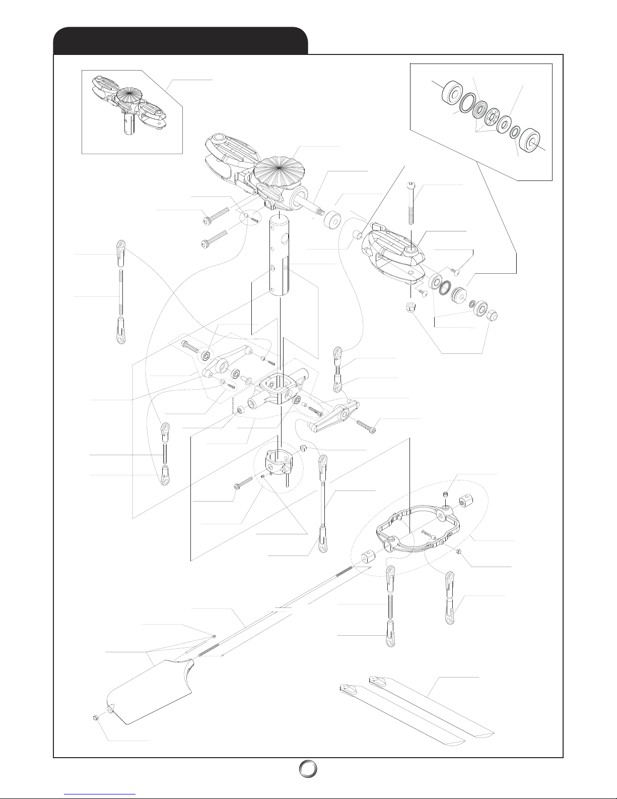
55
11.3
AH-1022
ROTOR HEAD ASSEMBLY
AH-2002
AH-3004
AH-2003
AH-3053
AH-0047
AH-2002
AH-3073
AH-3050
AH-2004
AH-3071
AH-0048
AH-3025
AH-0054
AH-3032
AH-2003
AH-0015
AH-3021
AH-0040
AH-3037
AH-3050
AH-200
3
54
0
AH-1519
AH-2003
AH-3023
AH-002
4
AH-303
7
AH-305
3
AH-302
1
AH-300
9
AH-100
9
AH-2004
AH-305
0
AH-302
2
AH-150
6
AH-307
4
AH-304
5
AH-004
6
AH-301
3
AH-000
5
AH-001
8
AH-001
7
AH-001
6
AH-002
3
AH-0055
* Note: Bevel
towards grip.
Grooved Washer
Larger ID Toward Hub
Grooved Washer
Smaller ID
Toward Grip
Flat Washer
M8x13x1 (x2)
Flat Washer
M5x9x1 (x2)
Thrust Bearing
M5x10x4 (x2)
AH-3071
MAIN ROTOR HEAD & SEESAW
Page 56

56
11.3
PART # DESCRIPTION QTY REMARKS
AH-0005 CENTER HUB ASSEMBLY
CENTER HUB 1
M3x06 SOCKET HEAD BOLT 4
AH-0015 FLYBAR
FLYBAR 2
AH-0016 SPINDLE SHAFT ASSEMBLY
SPINDLE SHAFT 1
NYLON LOCK NUT 1
AH-0017 DAMPER RUBBER
DAMPER RUBBER 4
AH-0018 GRIP SPACER
GRIP SPACER 2
AH-0023 ONE PIECE MAIN ROTOR HUB
ONE PIECE MAIN ROTOR HUB 1
AH-0024 CONTROL LEVER ASSEMBLY
ARM 1
FLY BAR STOPPER 2
STAINLESS STEEL BALL 2
M4x6 SET SCREW 2
M2x10 PHILLIPS HEAD SCREW 2
M2HEX NUT 2
AH-0040 FLYBAR PADDLE ASSEMBLY
FLYBAR PADDLE 2
M3 NYLON LOCK NUT 2
M4X06 SET SCREW 2
3X70 WEIGHT 2
AH-0046 MAIN ROTOR GRIP ASSEMBLY
MAIN ROTOR GRIP 2
JOINT BALL 2
M2x8 FLAT HEAD BOLT 2
AH-0047 SEESAW ARM ASSEMBLY
SEESAW ARM 2
M3 X 15 SOCKET HEAD BOLT 2
BEARING (L840ZZ) 4
SPACER 2
BALL JOINT 4
M2x10 PHILLIPS HEAD SCREW 4
AH-0048 SEESAW CENTER ASSEMBLY
SEESAW CENTER 1
M3x8 SEESAW CENTER BOLT 2
BEARING (L630ZZ) 2
BEARING (L840ZZ) 2
SPACER 2
AH-0054 ROTOR HUB ADAPTER ASSEMBLY
ROTOR HUB ADAPTER GUIDE PIN 2
M3x22 SOCKET HEAD BOLT 1
M3 NYLON LOCK NUT 1
M3s5 SET SCREW 2
AH-0055 SEESAW ARMS
SEESAW ARM 2
AH-1009 SEESAW SPACER ASSEMBLY
SEESAW SPACER 2
BEARING (L840ZZ) 2
M3x8 SEESAW CENTER BOLT 2
AH-1022 ROTOR HEAD ASSEMBLY
ROTOR HEAD ASSEMBLY 1
AH-1506 ROTOR GRIP BEARING & SPACER
T5-10 BEARING 2
5x9x1 WASHER 2
8x13x1 WASHER 2
AH-1519 MAIN ROTOR BLADE
04x600 MAIN ROTOR BLADE
PAIR
PARTS LIST
All screws, washers, nuts, and bearings on 11.7 Hardware List
Page 57
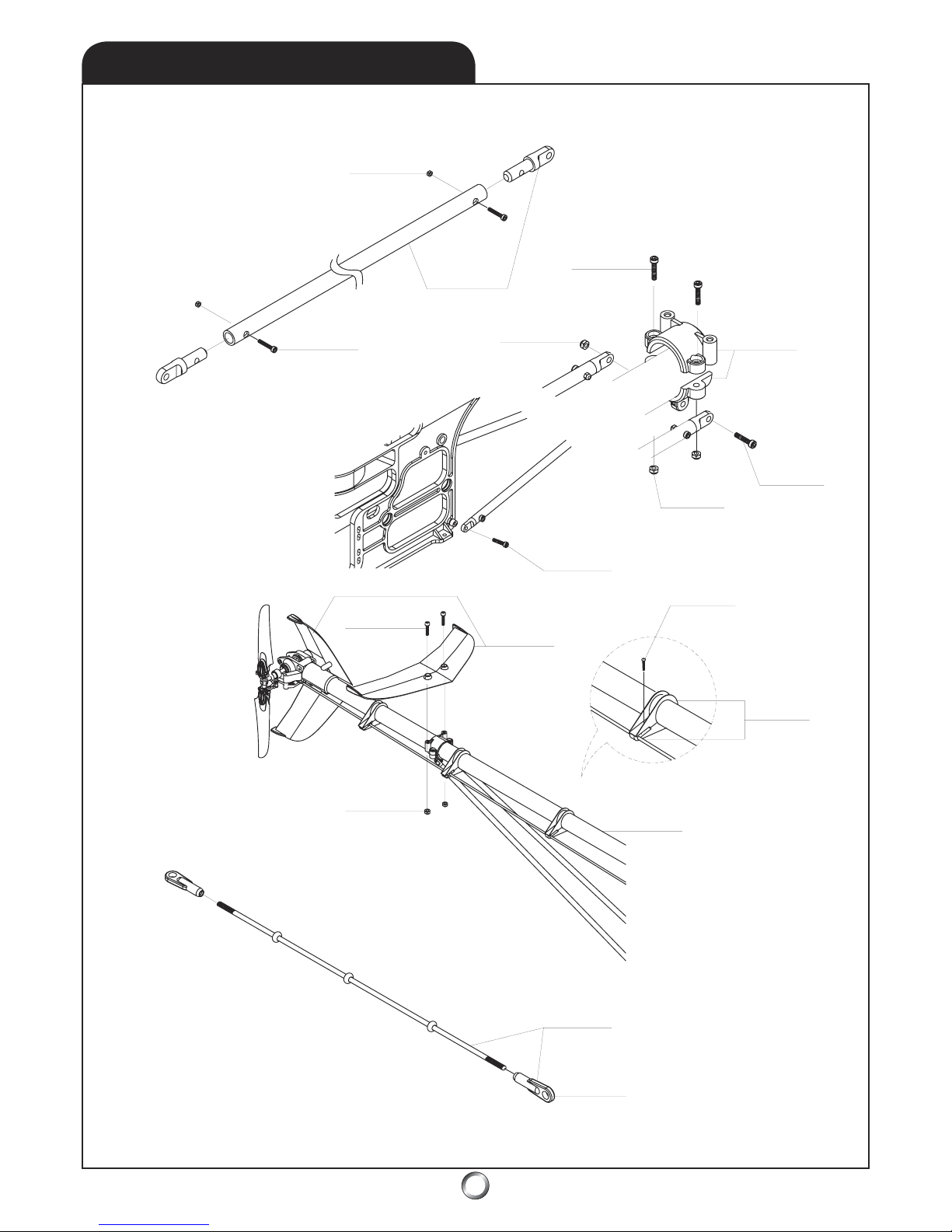
57
11.4
AH-3020
AH-1520
AH-3015
AH-302
1
AH-300
7
AH-0045
AH-300
8
AH-302
1
AH-300
6
AH-304
2
AH-3006
AH-004
4
AH-3021
AH-052
2
AH-151
8
AH-200
3
AH-152
1
SUPPORTS, GUIDES, & H-FIN
Page 58
58
11.4
PART # DESCRIPTION QTY REMARKS
AH-0044 TAIL FIN SET
HORIZONTAL FIN 1
VERTICAL FIN 1
M3x10 SOCKET HEAD BOLT 4
M3 NYLON LOCK NUT 2
AH-0045 TAIL SUPPORT CLAMP SET
TAIL SUPPORT CLAMP, UPPER 1
TAIL SUPPORT CLAMP, LOWER 1
M3x12 SOCKET HEAD BOLT 2
M3x22 SOCKET HEAD BOLT 1
M3 NYLON LOCK NUT 3
M3 FLAT WASHER 2
AH-0522 TAIL ROD GUIDE ASSEMBLY
PUSH ROD GUIDE 4
M2x8 TAPPING SCREW 4
AH-1518 TAIL BOOM
TAIL BOOM (04x690) 1
AH-1520 BOOM SUPPORT ASSEMBLY
ALUMINUM BOOM SUPPORT 2
BOOM SUPPORT END 4
M2.6x10 SOCKET HEAD BOLT 4
M2.6 NYLON LOCK NUT 4
M3x10 SOCKET HEAD BOLT 2
AH-1521 TAIL ROTOR PUSHROD ASSEMBLY
TAIL ROTOR PUSHROD 2
TAIL ROTOR PUSHROD BUSHING 4
BALL LINK END 2
PARTS LIST
All screws, washers, nuts, and bearings on 11.7 Hardware List
Page 59
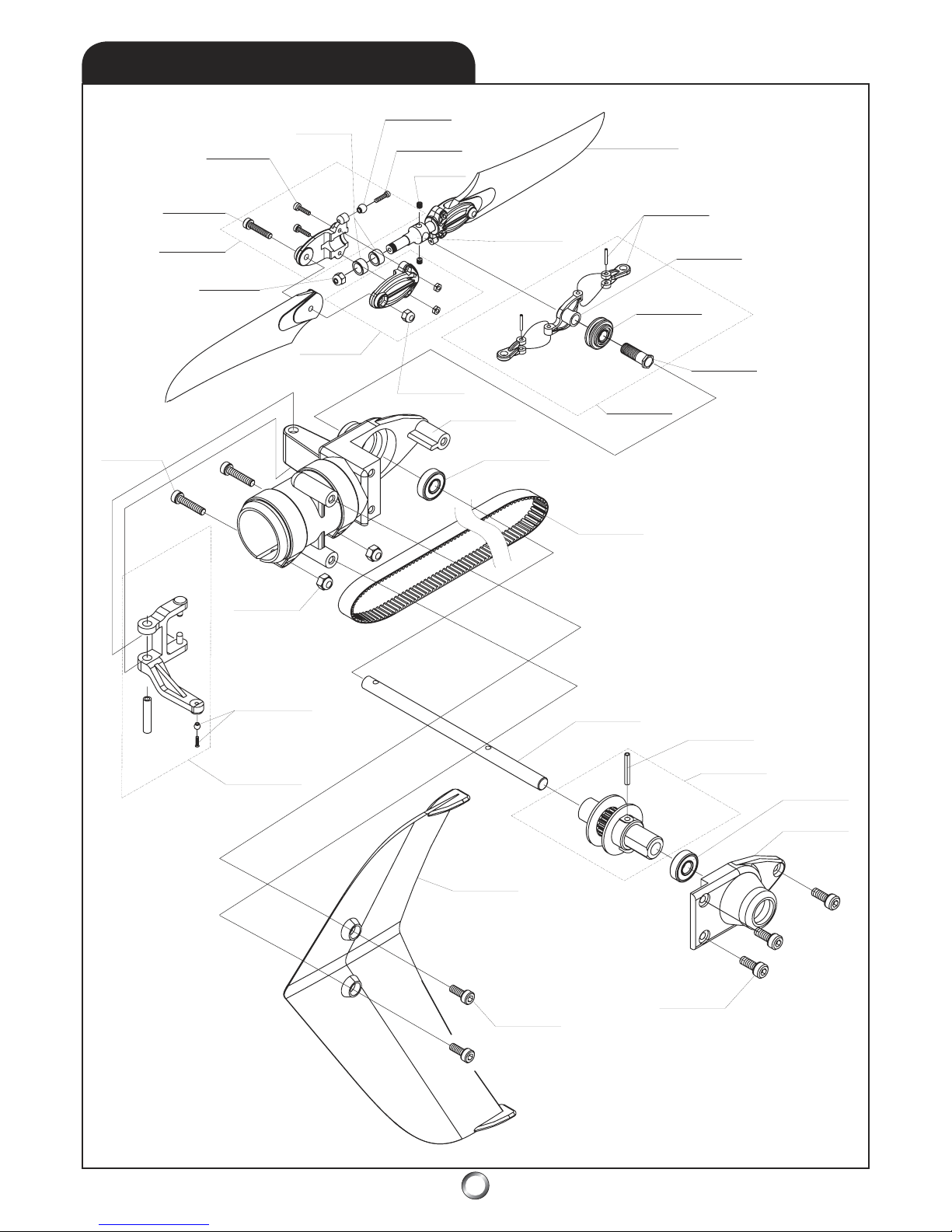
59
11.5
AH-3082
AH-3001
AH-3009
AH-0042
AH-3021
AH-2002
AH-3040
AH-3036
AH-0520
AH-004
3
AH-001
2
AH-001
3
AH-001
4
AH-100
5
AH-000
9
AH-3021
AH-004
1
AH-307
4
AH-050
8
AH-0042
AH-3003
AH-3020
AH-2002
AH-0010
AH-100
4
AH-306
6
AH-051
1
AH-307
4
AH-004
1
AH-300
4
AH-300
6
AH-0044
TAIL ROTOR, BELT, & V-FIN
Page 60

60
11.5
PARTS LIST
PART # DESCRIPTION QTY REMARKS
AH-0009 TAIL SLIDE RING ASSEMBLY
TAIL PITCH PLATE 1
TAIL PITCH LINK 2
TAIL PITCH LINK PIN 2
TAIL SLIDE RING 1
SLIDE RING BEARING 1
AH-0010 TAIL PITCH CONTROL LEVER ASSEMBLY
TAIL PITCH CONTROL LEVER 1
TAIL LEVER BUSHING 1
M2x8 PHILLIPS HEAD SCREW 1
STAINLESS STEEL BALL 1
AH-0012 TAIL PITCH LINK ASSEMBLY
TAIL PITCH LINK 2
TAIL PITCH LINK PIN 2
AH-0013 TAIL PITCH PLATE
TAIL PITCH PLATE 1
AH-0014 TAIL SLIDE RING
TAIL SILDE RING 1
TAIL SLIDE RING BEARING (L1170ZZ) 1
AH-0041 TAIL GEAR CASE ASSEMBLY
TAIL GEAR CASE, R 1
TAIL GEAR CASE, L 1
M2.6x12 SOCKET HEAD BOLT 2
M2.6 NUT 2
M3x6 SOCKET HEAD BOLT 3
AH-0042 TAIL ROTOR GRIP
TAIL ROTOR GRIP, R 2
TAIL ROTOR GRIP, L 2
STAINLESS STEEL BALL 2
M2x8 PHILLIPS HEAD SCREW 2
M2x8 SOCKET HEAD BOLT 4
M2 HEX NUT 4
M3x15 SOCKET HEAD BOLT 2
M3 NYLON LOCK NUT 2
AH-0043 TAIL ROTOR BLADES
TAIL ROTOR BLADE 2
AH-0044 TAIL FIN SET
HORIZONTAL FIN 1
VERTICAL FIN 1
M3x10 SOCKET HEAD BOLT 4
M3 NYLON LOCK NUT 2
AH-0508 TAIL DRIVE BELT
TAIL DRIVE BELT S3M - 1596 1
AH-0511 TAIL PULLEY ASSEMBLY
TAIL PULLEY 1
SPRING PIN, 2x14 1
AH-0520 TAIL ROTOR CENTER HUB ASSEMBLY
TAIL ROTOR CENTER HUB 1
M4x4 SET SCREW 2
M3 NYLON LOCK NUT 2
AH-1004 TAIL OUTPUT SHAFT
TAIL OUTPUT SHAFT 1
AH-1005 TAIL SLIDE RING SLEEVE
TAIL SLIDE RING SLEEVE 1
All screws, washers, nuts, and bearings on 11.7 Hardware List
Page 61
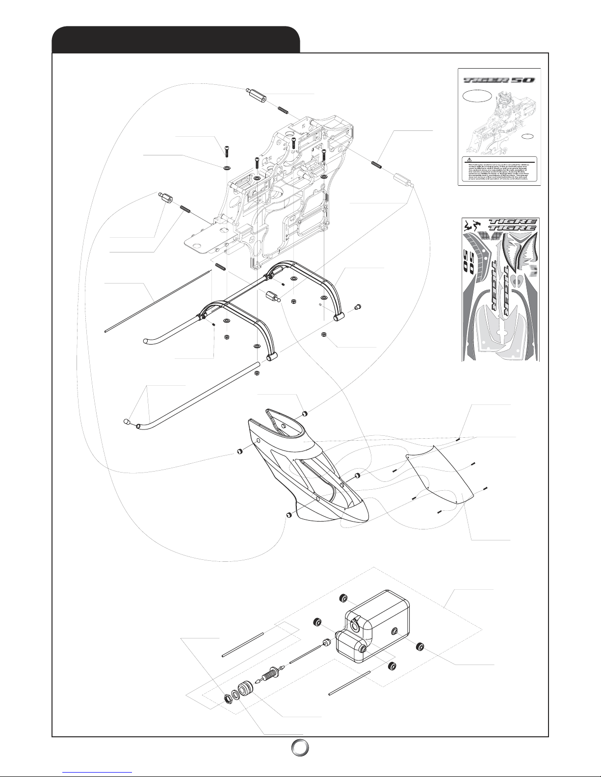
61
11.6
AH-0021
AH-3008
AH-3062
AH-0021
AH-3034
AH-1025
AH-3033
AH-0007
AH-0019
AH-3024
AH-1008
AH-3067
AH-005
3
AH-002
8
AH-101
7
AH-101
6
AH-304
2
AH-055
0
MANUAL
AH-054
9
DECAL SHEET
AH-002
1
AH-3021
AH-003
3
AH-303
5
eCCPM
electronic
Cyclic
Collective
Pitc
h
Mixing
.
.
.
.
.
PLEASE READ THIS MANUAL FULLY AND CAREFULLY!
Audacity Models . . . where performance exceeds expectations!
For updates, visit:
www.audacitymodels.com
SKIDS, CANOPY, & FUEL TANK
Page 62

62
11.6
PARTS LIST
PART # DESCRIPTION QTY REMARKS
AH-0007 LANDING SKID ASSEMBLY
LANDING SKID 2
SKID CAP 4
AH-0019 RUBBER GROMMET SET
RUBBER GROMMET 4
AH-0021 CABIN MOUNT STANDOFF SET
FRONT STANDOFF (10mm x 1) 2
REAR STANDOFF (20mm x 1) 2
AH-0028 FUEL TANK ASSEMBLY
FUEL TANK (14 oz) 1
FUEL TANK CLUNK PICKUP 1
FEED NIPPLE 1
RUBBER TANK GROMMET 1
SILICONE FUEL TUBE 1
M7 FLAT WASHER (7x12x1) 1
M7 NUT 2
RUBBER MOUNTING GROMMET 4
AH-0033 LANDING GEAR STRUT ASSEMBLY
LANDING GEAR STRUT 2
M3x6 SET SCREW 4
AH-0053 RUBBER MOUNTING GROMMET SET
RUBBER MOUNTING GROMMET 4
AH-0549 STICKER
STICKER 1
AH-0550 MANUAL
MANUAL 1
AH-1008 FUEL TANK RUBBER GROMMET
FUEL TANK RUBBER GROMMET 2
AH-1016 BODY SET
BODY 1
CANOPY 1
M2x8 TAPPING SCREW 6
RUBBER GROMMET 4
AH-1017 CANOPY ASSEMBLY
CANOPY 1
M2x8 TAPPING SCREW 6
AH-1025 ANTENNA GUIDE TUBE
A
NTENNA GUIDE TUBE 1
All screws, washers, nuts, and bearings on 11.7 Hardware List
Page 63
63
PART # DESCRIPTION QTY PART # DESCRIPTION QTY
AH-2001 STAINLESS STEEL BALL JOINT SET AH-3042 M2x8 SELF TAPPING SCREW 1
STAINLESS STEEL BALL JOINT 1 AH-3044 M2.6x12 SELF TAPPING SCREW 1
M2x8 PHILLIPS HEAD SCREW
1
A
H-3045M3x6 SELF TAPPING SCREW 1
A
H-2002 STAINLESS STEEL BALL JOINT SET
STAINLESS STEEL BALL JOINT 1
M2x10 PHILLIPS HEAD SCREW 1
PART # DESCRIPTION QTY
AH-2003 HD BALL LINK END, LONG 1 AH-3050 M2.3x12 THREADED ROD 1
A
H-2004 1
A
H-3051 M2.3x20 THREADED ROD 1
A
H-3052 M2.3x30 THREADED ROD 1
A
H-3053 M2.3x40 THREADED ROD 1
PART # DESCRIPTION QTY
A
H-3055M2.3x50 THREADED ROD 1
A
H-3001 M2x8 SOCKET HEAD BOLT 1
A
H-3002 M2x10 SOCKET HEAD BOLT 1
AH-3003 M2.6x12 SOCKET HEAD BOLT 1
PART # DESCRIPTION QTY
AH-3004 M3x6 SOCKET HEAD BOLT 1 AH-3060 M2 FLAT WASHER 1
AH-3005 M3x8 SOCKET HEAD BOLT 1 AH-3061 M2.6 FLAT WASHER 1
A
H-3006 M3x10 SOCKET HEAD BOLT 1
A
H-3062 M3 FLAT WASHER 1
A
H-3007 M3x12 SOCKET HEAD BOLT 1
A
H-3008 M3x14 SOCKET HEAD BOLT 1
AH-3009 M3x15 SOCKET HEAD BOLT 1
PART # DESCRIPTION QTY
A
H-3010 M3x22 SOCKET HEAD SHOULDER BOLT 1
A
H-3063 M3 LOCK WASHER 1
A
H-3011 M3x30 SOCKET HEAD BOLT 1
A
H-3012 M3x38 SOCKET HEAD BOLT 1
AH-3013 M4x30 SOCKET HEAD SHOULDER BOLT 1
PART # DESCRIPTION QTY
A
H-3014 M3x35 SOCKET HEAD BOLT 1
A
H-3064 M2 PERMANENT PUSH NU
T
1
A
H-3015M2.6x10 SOCKET HEAD BOLT 1
A
H-3025M3x3 SOCKET HEAD BOLT 1
PART # DESCRIPTION QTY
A
H-3065M11 SNAP RING 1
PART # DESCRIPTION QTY
A
H-3020 M2.6 NYLON LOCK NUT 1
AH-3021 M3 NYLON LOCK NUT 1
PART # DESCRIPTION QTY
A
H-3022 M4 NYLON LOCK NUT 1
A
H-3066 1
PART # DESCRIPTION QTY PART # DESCRIPTION QTY
A
H-3023 M2 HEX NU
T
1
A
H-3067 7x12x1 FLAT WASHER 1
A
H-3024 M7 HEX NU
T
1
PART # DESCRIPTION QTY
PART # DESCRIPTION QTY
AH-3071 L840ZZ 4x8x3 1
AH-3030 M3x3 SET SCREW 1 AH-3072 HF0612 Oneway 6x10x12 1
AH-3031 M3x4 SET SCREW 1 AH-3073 L630ZZ 3x6x2.5 1
AH-3032 M3x5 SET SCREW 1 AH-3074 L1350ZZ 5x13x4 1
AH-3033 M3x6 SET SCREW 1 AH-3075 L1050ZZ 5x10x4 1
AH-3034 M3x12 SET SCREW 1 AH-3077 L1910ZZ 10x19x7 1
AH-3035 M3x15 SET SCREW 1 AH-3080 R1950ZZ 5X19X6 1
AH-3036 M4x4 SET SCREW 1 AH-3081 R1960ZZ 6x19x6 1
A
H-3037 M4x6 SET SCREW 1
A
H-3082 R840ZZ 3x7x3 1
PART # DESCRIPTION QTY
AH-3040 M2x8 PHILLIPS HEAD SCREW 1
A
H-3041 M2x10 PHILLIPS HEAD SCREW 1
SPRING PINS
BALL LINK & ENDS
SOCKET HEAD BOLTS
NYLON LOCK NUTS
SELF TAPPING SCREWS
THREADED ROD
FLAT WASHERS
LOCK WASHERS
PERMANENT PUSH NUTS
SNAP RINGS
FLAT WASHERSHEX NUTS
SET SCREWS
PHILLIPS HEAD SCREWS
BEARINGS
HARDWARE LIST
11.7
Page 64
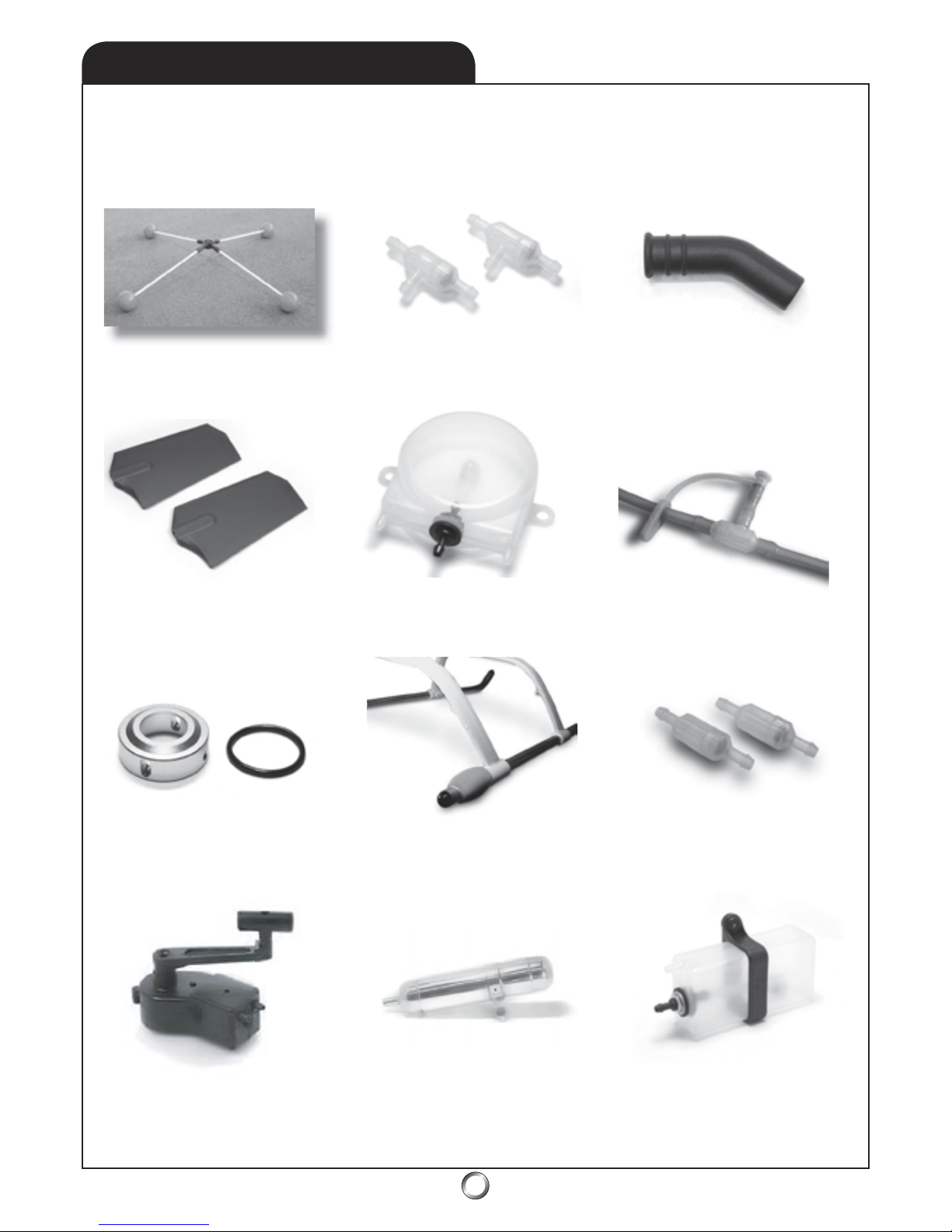
64
12.0
ACCESSORIES
PRO-0063 - Training Gear PRO-0004 - Filter Filter T PRO-0062 - Exhaust Deflector 35
o
PRO-0061 - 3D Hopper Tank (3oz)
PRO-0057P - 3D Paddles (pink)
PRO-0057W (white), PRO-0059 (yellow)
PRO-0003 - Shutoff & Plug (2-yellow)
PRO-0065 - Limited Slip Drive PRO-0056 - Fuel Filters (2-clear)PRO-0009P - Skid Guard (pink)
PRO-0009W (white), PRO-0009Y (yellow)
PRO-0053 - PRO Muffler 50 PRO-0016 - Hopper Tank (2oz)
PRO-0065 - PRO mini-pump
(compatible w/glo-fuel and gasoline)
Ult
ra high qua
lit
y accessories, which won’t break the bank, crafted
by our crew. PROMODELER . . . when it’s more than a hobby
!
TM
www.promodeler.com
www.promodeler.com
Page 65
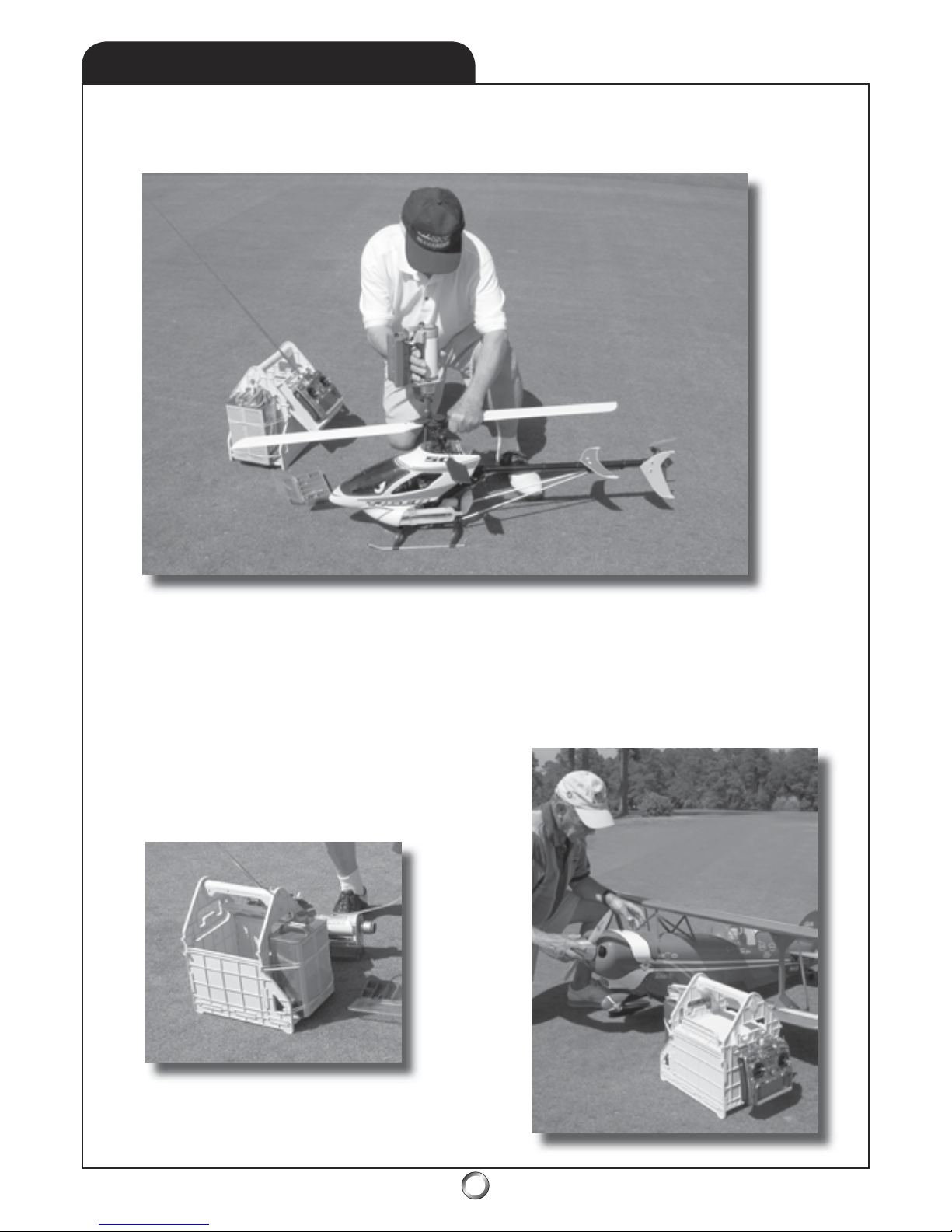
65
12.1
ACCESSORIES
PRO-0050 - Flight Box (yellow)
www.promodeler.com
Ult
ra high qua
lit
y accessories, which won’t break the bank, crafted
by the crew at PROMODELER . . . when it’s more than a hobby!
TM
Designed to store your transmitter, starter and battery, a gallon of fuel, plus the usual accoutrements
like spare plugs, tools, field charger, battery tester and more, the superb PROMODELER Flight Box is
perf
ect for the experienced pro. Molded in bright Cub yellow to reflect the sun, the strong and
durable PVC design assmebles in minutes using a screwdriver - no painting! With a nifty storage top
that lif
ts and pivots into place transforming into a conveniently angled transmitter stand, your tranny
is both positioned for ready access and off the ground. Unlike old-fashioned painted wood, clean up
is easy too as the fuel proof Flight Box shines with
just soap and water.
Combining high-tech design and
low-tech prac
ticality, for what’s really needed at the
field, the pros pack a PROMODELER Flight Box.
Page 66

66
ACCESSORIES
12.2
Better than show-and-tell because you can play it over and
over. Watch both how a properly set-up helicopter perf
orms,
and hear what it should sound like! Learn the insider’s tips
and tricks as different mechanical set-ups are performed.
Fr
om what a beginner needs, through an expert’s 3D set-up,
this program features several different helicopters. Models
range from sport and aerobatic helicopters through electric
and even scale. Two leading radio-brands are demonstrated
(Futaba and JR) to include conventional and CCPM set-ups!
There are even tips for setting up helicopter engines, preventive maintenance, tools,
flight simulators and more! But that’s
not all as you’
re guided through a flight training process that
starts with skidding an inch off the ground and culminates
in your learning the nose-in hover.
Because helicopter flight
starts and ends in a hover, this 2-hour long program is perfect
for gaining the confidence to set your model up correctly and
learn to hover it . . . you can succeed!
RCB002 - R/C Basics: Hover - Flight Training
At last, an easy way to learn to fly R/C helicopters! From the producers
of modelSPORT video-magazine comes R/C Basics: Hover - Flight Training!
Surf to www.modelsport.com to get your own personal copy!
Learn to tune and adjust model engines like a pro! From the producers
of modelSPORT video-magazine comes R/C Basics: aboutENGINES
R/C model engines can be both frustrating and confusing,
but
with the help of this nearly 3-hour long program, you’
ll soon
be tuning engines like a pro - it’s
loaded with tips! From a
standard .46-class ABC engine to sophisticated multi-c
ylinder
4-strokes and gas burners, you’
ll soon be up to speed. Learn
about fuel systems, equipment and tools,
safety, and even
about gasoline vs. alcohol fuels.
You’ll learn about Walbro
pump-carburetors, how to adjust valves, tips and tricks for
fine tuning 2-needle carbs, heat ranges of glo plugs,
and even
arcane secrets like how to read spark plug color! You’
ll also
learn about engine handling techniques, engine assembly
tricks, and more! ABC-class engines break in differently from
ringed helicopter engines - and you’ll know why and how to
do it properly. Why take years to learn what the pros know?
RCB003 - R/C Basics: aboutENGINES
www.modelsport.com
www.modelsport.com
Page 67
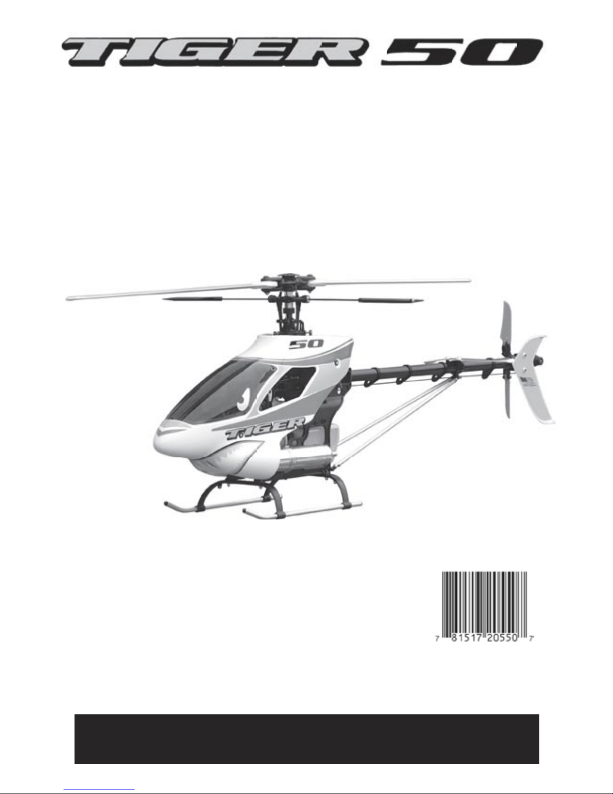
67
Audacity Models . . . where performance exceeds expectations!
www.audacitymodels.com
A paper document like this manual freezes in time the technical knowledge, how-to tips, programming
ideas, and everything else we subsequently learn about the Tiger 50. We encourage you to visit our
website for updates, as well as other bits of info
rmation we may discover and share.
 Loading...