

Page 1
User manual
WP205 & WP210
audac.eu
Page 2

ADDITIONAL INFORMATION
This manual is put together with much care, and is as complete as could be on the publication date. However,
updates on the specications, functionality or software may have occurred since publication. To obtain the latest
version of both manual and software, please visit the Audac website @ www.audac.eu.
WP2xx - User manual02
Page 3

Table of contents
Introduction 05
Wall panel - Microphone & line receiver � � � � � � � � � � � � � � � � � � � � � � � � � � � � � � � � � � � � � � � � � � � � � 05
Precautions 06
Chapter 1 08
Overview front panel � � � � � � � � � � � � � � � � � � � � � � � � � � � � � � � � � � � � � � � � � � � � � � � � � � � � � � � � � � � � � 08
Front panel description � � � � � � � � � � � � � � � � � � � � � � � � � � � � � � � � � � � � � � � � � � � � � � � � � � � � � � � � � � � 08
Overview rear panel WP205 � � � � � � � � � � � � � � � � � � � � � � � � � � � � � � � � � � � � � � � � � � � � � � � � � � � � � � � 09
Rear panel description WP205 � � � � � � � � � � � � � � � � � � � � � � � � � � � � � � � � � � � � � � � � � � � � � � � � � � � � � 09
Overview rear panel WP210 � � � � � � � � � � � � � � � � � � � � � � � � � � � � � � � � � � � � � � � � � � � � � � � � � � � � � � 010
Rear panel description WP210 � � � � � � � � � � � � � � � � � � � � � � � � � � � � � � � � � � � � � � � � � � � � � � � � � � � � 010
Chapter 2 011
Quick start guide � � � � � � � � � � � � � � � � � � � � � � � � � � � � � � � � � � � � � � � � � � � � � � � � � � � � � � � � � � � � � � � � � 011
Chapter 3 012
Connections � � � � � � � � � � � � � � � � � � � � � � � � � � � � � � � � � � � � � � � � � � � � � � � � � � � � � � � � � � � � � � � � � � � � 012
Technical specications 014
Notes 015
WP2xx - User manual 03
Page 4

WP2xx - User manual04
Page 5

Introduction
Wall panel - Microphone & line receiver
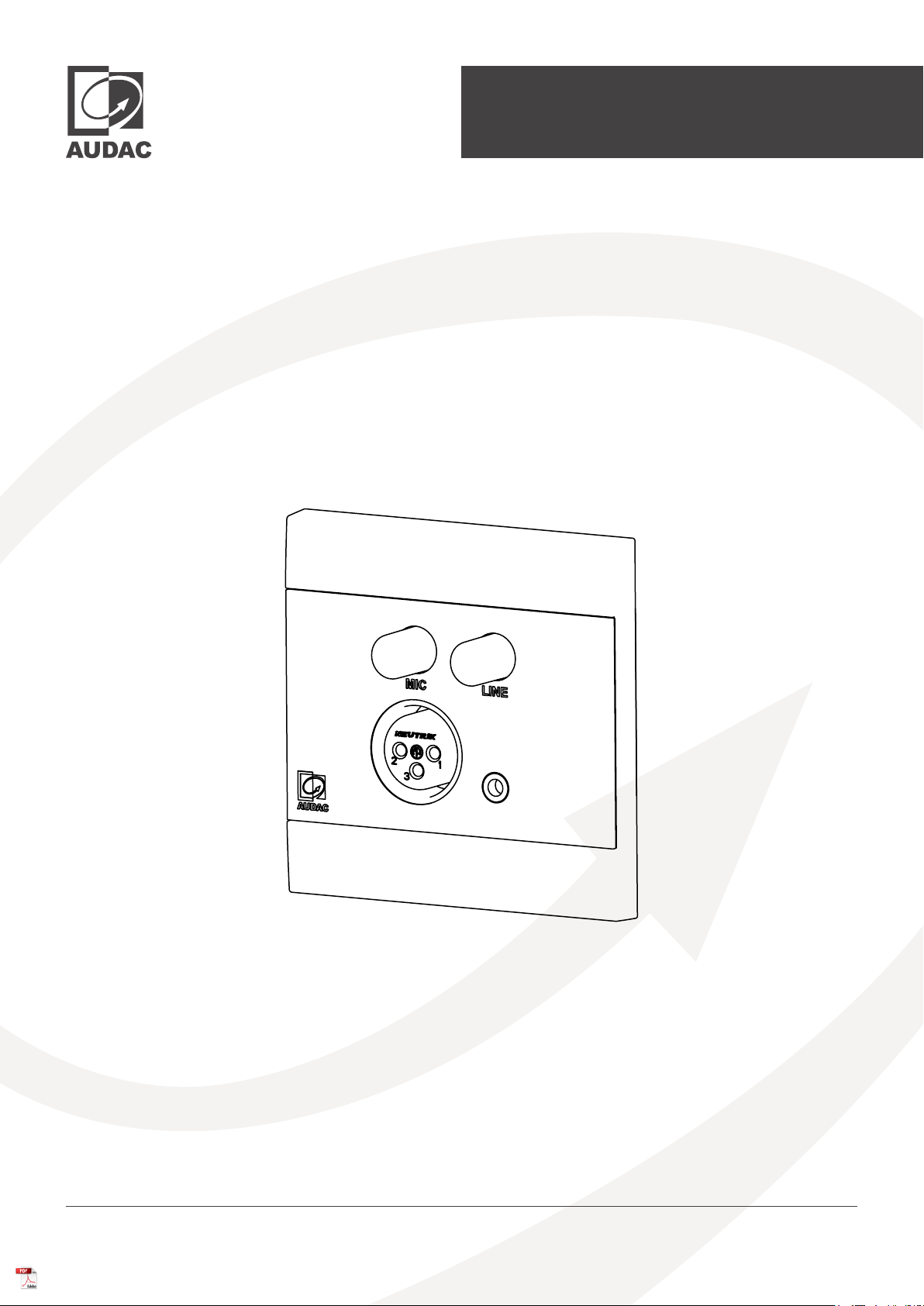
The WP205 & WP210 are remote wall mixers. The WP210 can be used with various AUDAC devices, while the WP205 is
an external wall mixer designed to be used only with the ARES5A. It converts the signal coming from a stereo line-level audio
source (such as a tuner, mobile devices, ... ) or balanced microphone a the level corresponding to the differential signal input
making it possible to transfer high-quality audio over long distances between the wall panel and the loudspeaker, by just
using inexpensive twisted-pair CAT5e or better cabling. On the front side of the wall panel, there is a 3.5 mm jack stereo line
input connection available together with a balanced XLR microphone input, both provided with their own knob which allows
the signals to be mixed together. The wall panels are available in 2 colours and is compatible with most standard EU (80x80
mm) style in-wall boxes for solid and hollow walls. With the Elegant front panel, it will blend into any environment
WP2xx - User manual 05
Page 6
Precautions
READ FOLLOWING INSTRUCTIONS FOR YOUR OWN SAFETY
ALWAYS KEEP THESE INSTRUCTIONS. NEVER THROW THEM AWAY
ALWAYS HANDLE THIS UNIT WITH CARE
HEED ALL WARNINGS
FOLLOW ALL INSTRUCTIONS
NEVER EXPOSE THIS EQUIPMENT TO RAIN, MOISTURE, ANY DRIPPING OR SPLASHING LIQUID. AND NEVER PLACE AN OBJECT FILLED WITH
LIQUID ON TOP OF THIS DEVICE
NO NAKED FLAME SOURCES, SUCH AS LIGHTED CANDLES, SHOULD BE PLACED ON THE APPARATUS
DO NOT PLACE THIS UNIT IN AN ENCLOSED ENVIRONMENT SUCH AS A BOOKSHELF OR CLOSET. ENSURE THERE IS ADEQUATE
VENTILATION TO COOL THE UNIT. DO NOT BLOCK THE VENTILATION OPENINGS.
DO NOT STICK ANY OBJECTS THROUGH THE VENTIL ATION OPENINGS.
DO NOT INSTALL THIS UNIT NE AR ANY HEAT SOURCES SUCH AS RADIATORS OR OTHER APPARATUS THAT PRODUCE HEAT
DO NOT PLACE THIS UNIT IN ENVIRONMENTS WHICH CONTAIN HIGH LEVELS OF DUST, HEAT, MOISTURE OR VIBRATION
THIS UNIT IS DEVELOPED FOR INDOOR USE ONLY. DO NOT USE IT OUTDOORS
PLACE THE UNIT ON A STABLE BASE OR MOUNT IT IN A STABLE RACK
ONLY USE ATTACHMENTS & ACCESSORIES SPECIFIED BY THE MANUFACTURER
UNPLUG THIS APPARATUS DURING LIGHTNING STORMS OR WHEN UNUSED FOR LONG PERIODS OF TIME
ONLY CONNECT THIS UNIT TO A MAINS SOCKET OUTLET WITH PROTECTIVE E ARTHING CONNECTION
THE MAINS PLUG OR APPLIANCE COUPLER IS USED AS THE DISCONNECT DEVICE, SO THE DISCONNECT DEVICE SHALL BE READILY
OPERABLE
USE THE APPARATUS ONLY IN MODERATE CLIMATES
CAUTION - SERVICING
This product contains no user serviceable parts. Refer all servicing to qualied service personnel. Do
not perform any servicing (unless you are qualied to)
EC DECLARATION OF CONFORMITY
This product conforms to all the essential requirements and further relevant specications described
in following directives: 2014/30/EU (EMC) & 2014/35/EU (LVD).
WASTE ELECTRICAL AND ELECTRONIC EQUIPMENT (WEEE)
The WEEE marking indicates that this product should not be disposed with regular household waste
at the end of its life cycle. This regulation is created to prevent any possible harm to the environment
or human health.
This product is developed and manufactured with high quality materials and components which can be
recycled and/or reused. Please dispose this product at your local collection point or recycling centre for
electrical and electronic waste. This will make sure that it will be recycled in an environmentally friendly
manner, and will help to protect the environment in which we all live.
WP2xx - User manual06
Page 7

WP2xx - User manual 07
Page 8
Chapter 1
Overview front panel
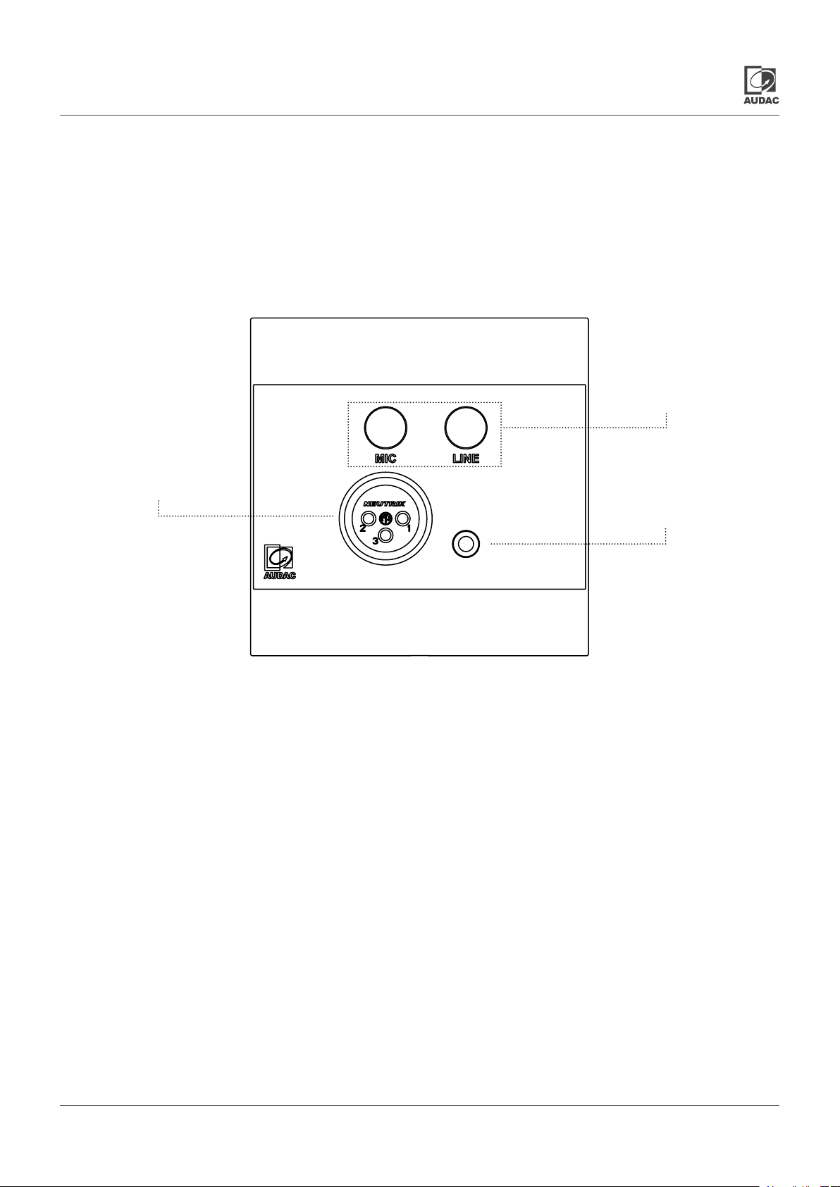
On the front side of the wall panel, there is an unbalanced 3.5 mm jack stereo line input connection available
together with a balanced XLR microphone input, both provided with their own knob which allows the signals
to be mixed together.
Balanced microphone input
Potentiometer for signal control
Front panel description
Balanced microphone input
A balanced microphone can be connected to this XLR input connector. For powering condenser microphones,
phantom power can be enabled.
Unbalanced line input
An unbalanced stereo audio source can be connected to this 3.5mm jack stereo line input.
Unbalanced stereo line input
Potentiometers for signal control
The individual signal levels for the line and microphone inputs can be adjusted with these potentiometers.
This feature allows for the signals to be mixed together.
WP2xx - User manual08
Page 9

Overview rear panel WP205
The rear side of the WP205 contains an 8-pin Terminal Block connector. Below of the 8-pin connector are some
DIP switches. With these switches certain functions can be switched on or off depending on the situation where
the WP is in.
Terminal block output connection
Rear panel description WP205
8-pin terminal block (3.81 mm pitch) output connection
The rear of the WP205 contains an 8-pin Euro-Terminal Block connector. For more information on how to
make the connections can be found under “Connecting” in Chapter 3 of this manual.
DIP switches
DIP switch enable / disable output level +12 dBV: When the option of +12 dBV is enabled, the wall panel is
compatible with remote input devices. When it is disabled, the wall panel is compatible with standard line
inputs (0 dBV)
DIP switch mono / stereo: With this switch, the operation mode can be switched between mono and stereo
mode for the Line or Mic signal. When the wall panel is used in mono mode, the input signal applied to the
left input signal will be available on both left and right outputs.
DIP switch for phantom power
DIP switch enable / disable output level +12 dBV
DIP switch mono / stereo for Line or Mic
DIP switch enable / disable phantom power: The phantom power for the microphone input can be enabled
or disabled.
WP2xx - User manual 09
Page 10
Overview rear panel WP210
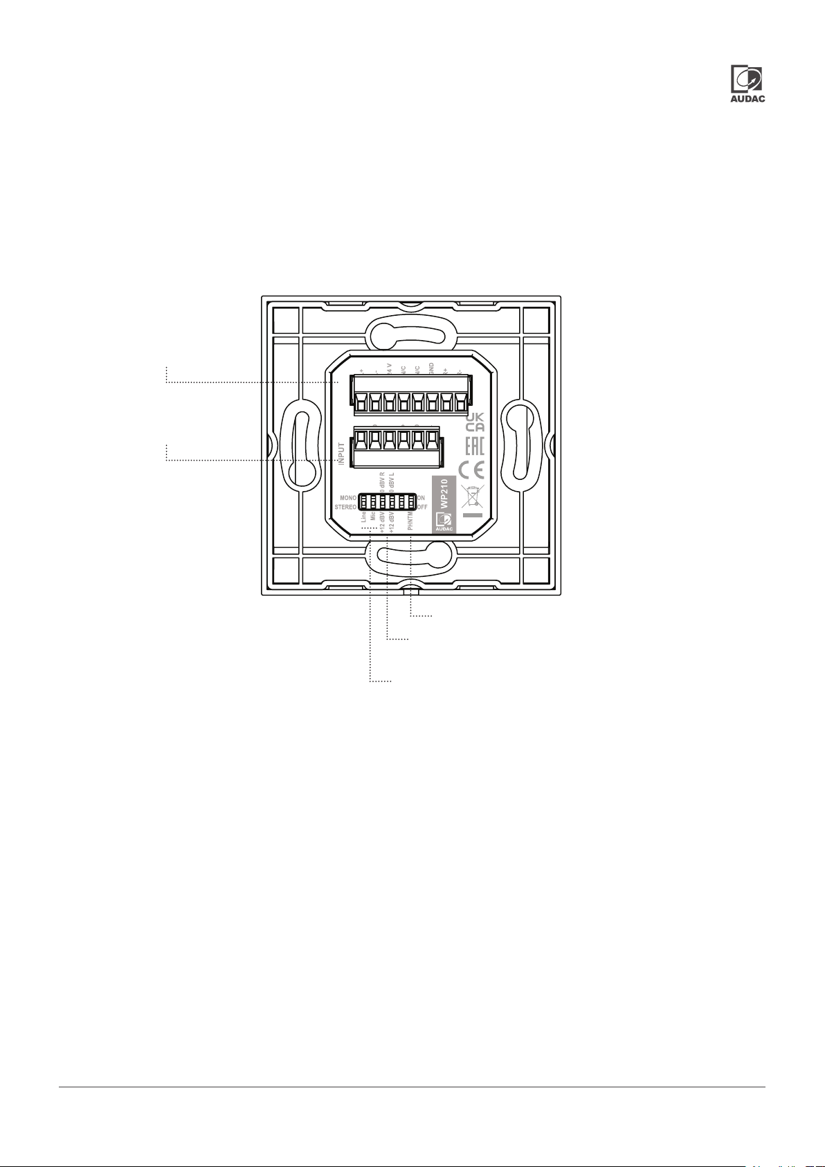
The rear of the WP210 contains an 8-pin Terminal Block connector, which is used to connect the wall panel to the
RJ45 connector. Below the 8-pin connector is a 6-pin connector. This input connector is a duplicate of the line and
mic input but for permanent connections. Below of the 6-pin connector are some DIP switches. These switches
allow certain functions to be turned on or off, depending on the situation the WP is in.
Terminal block output connection
Terminal block input connection
Rear panel description WP210
8-pin terminal block (3.81 mm pitch) output connection
The rear of the WP210 contains an 8-pin Euro-Terminal Block connector, where the wall panel must be
connected to the RJ45 connector. For more information on how to make the connections can be found
under “Connecting” in Chapter 3 of this manual.
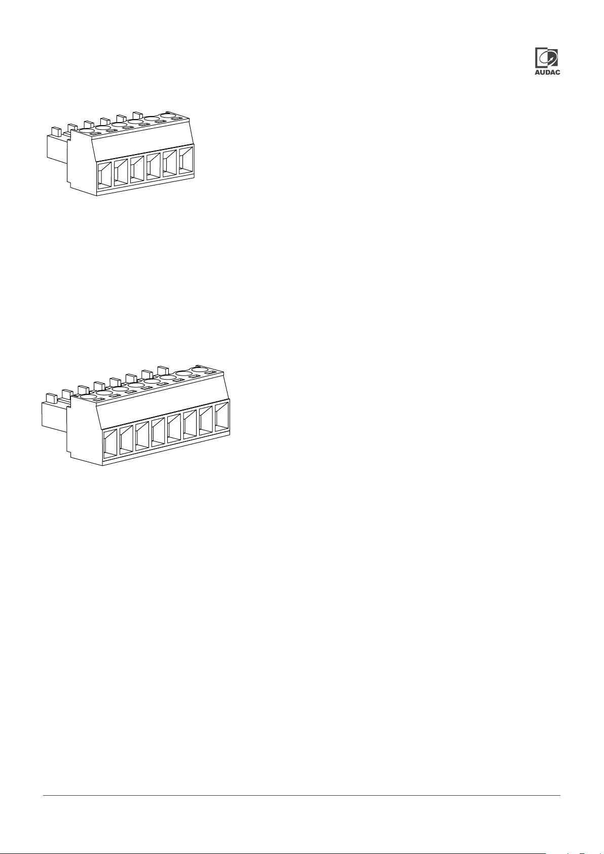
6-pin terminal block (3.81 mm pitch) input connection
The 6-pin Euro-Terminal block is an input connector. This is a duplicate of the mic and line inputs but for a
permanent connection.
DIP switch for Phantom power
DIP switch enable / disable output level +12 dBV
DIP switch mono / stereo for Line or Mic
WP2xx - User manual010
Page 11
DIP switches
DIP switch enable / disable phantom power: The phantom power for the microphone input can be enabled
or disabled.
DIP switch enable / disable output level +12 dBV: When the option of +12 dBV is enabled, the wall panel is
compatible with remote input devices. When it is disabled, the wall panel is compatible with standard line
inputs (0 dBV)
DIP switch mono / stereo: The operation mode can be switched between mono and stereo mode with this
switch. When the wall panel is used in mono mode, the input signal applied to the left input signal will be
available on both left and right outputs.
Chapter 2
Quick start guide
This chapter guides you through the setup process for a basic setup where a WP205 or 210 should be
connected to a loudspeaker system with wired network. Install your wall panel on the desired location by
means of the optional available WB45S/FS (for solid walls) or WB45S/FG (for hollow walls) installation boxes.
Provide a twisted pair cable (CAT5E or better) from the receiving device to the wall panel.
Connect the 8-pin terminal block to a receiving device with a twisted pair cable. After all those connections
are made, just plug-in the connectors of the twisted pair cable, plug in the mains power on the loudspeaker
side and your system is ready for operation.
You can plug in your line and microphone audio sources to the wall-panel, and your sounds should be
audible through the system.
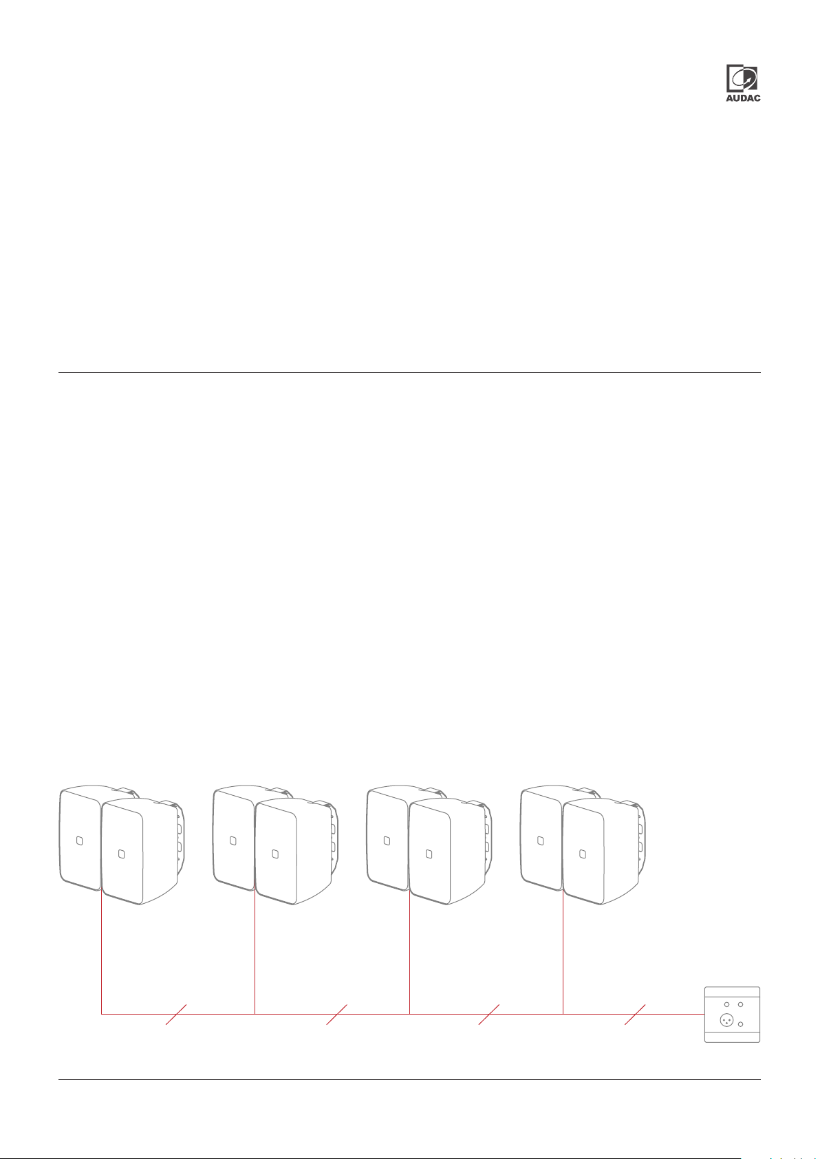
Connecting multiple ARES sets to a single remote input
ARES5A set 4
At tention:
Connect pin 3 & 6 to single
speaker
Connect
8 conductors
Connect
6 conductors
Connect
6 conductors
ARES5A set 3ARES5A set 2ARES5A set 1
Connect
6 conductors
WP205
Do not connect pin 3 & 6 Do not connect pin 3 & 6 Do not connect pin 3 & 6
Audio pairs : Pin 1 & 2 + Pin 7 & 8
Power supp l y : Pin 3 & 6
WP2xx - User manual 011
Page 12
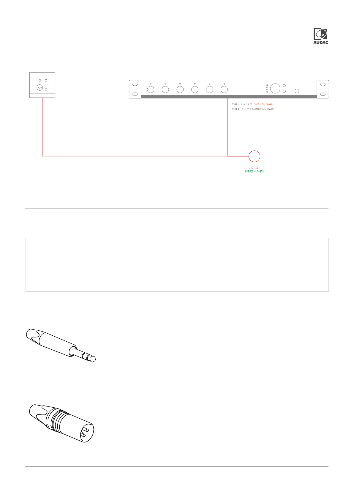
Connecting a remote input to a line input connection
WP2xx series
0 dBV output
(DIP Switch)
PSD241
Shielded balanced audio or CAT networking cable
+
Chapter 3
PRE116
PRE116
AUDAC
Connections
CONNECTION STANDARDS
The in- and output connections for AUDAC audio equipment are performed according to international wiring
standards for professional audio equipment
3.5 mm jack:
For unbalanced line input connections
Tip:
Ring:
Sleeve:
XLR
For balanced line input connections
Left
Right
Ground
PIN 1:
PIN 2:
PIN 3:
Ground
Signal +
Signal -
WP2xx - User manual012
Page 13
Wall panel rear audio input connection:
6-pin terminal block connector (3.5mm pitch)
PIN 1:
PIN 2:
PIN 3:
PIN 4:
PIN 5:
PIN 6:
Mic -
GND
Mic +
Line L
GND
Line R
1
6
Terminal block (Audio, +24V DC)
For connection to Wall Panels
The 8-pin Euro-Terminal Block on the rear side of the WP205 or WP210 should be connected to twisted pair cabling.
The maximum cable distance between the input unit and the speaker system can reach up to 100 meter. To ensure
a proper working of the system, all 8 conductors of the twisted pair cable have to be connected according to the
table below.
Pin 1 White-Orange Left +
Pin 2 Orange Left -
Pin 3 White-Green +24V DC
Pin 4 Blue Not connected
Pin 5 White-Blue Not connected
Pin 6 Green GND
8
Pin 7 White-Brown Right +
Pin 8 Brown Right -
1
WP2xx - User manual 013013
Page 14
Technical specications
Inputs Type
Connector Front: 3.5mm jack
Impedance 7,7 kOhm
Sensitivity -6 dBV / +26 dBV
THD+N <0,2%
Signal / Noise 72 dB
Type
Connector Front: female XLR
Impedance 1 kOhm
Sensitivity -45 dBV / -10 dBV
THD+N <0,02%
Signal / Noise > 75 dB
Output Type
Connector 8-pin terminal block 3.81mm
Stereo unbalanced line
Rear: 6-pin terminal block 3.81mm
(for WP210 only)
Balanced microphone
Rear: 6-pin terminal block 3.81mm
(for WP210 only)
Stereo
Output level Switch between 0dBV and 12 dBV
Power consumption
Power supply 17V - 24V
Phantom power 24V DC (depending on input voltage)
Noiseoor -76.5 dBV
Dimensions 80 x 80 x 52.7 mm (W x H x D)
Built-In depth 47 mm
Colours Black (RAL9005)
Front nish ABS with glass
Accessoiries Solid wall WB45S/FS
Hollow wall WB45S/FG
Compatible devices ARES5A
< 1,5W
White (RAL9003)
MTX48 / MTX88
AMP523
APG20
WP2xx - User manual014
Page 15

Notes
WP2xx - User manual 015
Page 16

Discover more on audac.eu
 Loading...