

Page 1

MMP40
User Manual
www.audac.eu
Page 2

2
ADDITIONAL INFORMATION
This manual is put together with much care, and is as complete as could be on the
publication date. However, updates on the specifications, functionality or software
may have occurred since publication. To obtain the latest version of both manual and
software, please visit the Audac website @ www.audac.eu.
Page 3

3
Index
Introduction 5
Precautions 6
Safety requirements 6
Caution servicing 7
EC Declaration of Conformity 7
Waste of Electrical and Electronic Equipment (WEEE) 7
Chapter 1: Connections and connectors 8
Connection standards 8
Chapter 2: Overview MMP40 9
Chapter 3: Using the MMP40 10
Module screen 10
Media player mode 11
Media player settings 12
Media recorder mode 13
Media recorder settings 14
Chapter 4: Installing the MMP40 16
Chapter 5: Additional information 18
Technical specifications 18
Notes 19
Page 4

4
Page 5

5
Introduction
SourceCon™ media player & recorder module
The MMP40 is a professional media player & recorder featuring SourceCon™ modular
technology. This unique technology guarantees true plug & play implementation to any
compatible device. When inserted to a supporting slot, the module is instantly installed,
discovered and ready for operation without requiring any additional internal wiring or
complex configuration.
The MMP40 supports media playback and / or recordings from/to USB storage drives
in a wide variation of compressed and lossless audio formats. The USB media carrier
shall be inserted to the corresponding slot on the controlling main unit. Media playback
is possible in MP3, OGG, AAC, FLAC, WMA and WAV filetypes, while recordings can be
made in MP3, OGG and WAV filetypes.
All media information such as track, artist, playback mode, ... including even graphical
album covers can be retrieved from the MMP40, allowing displaying it on the controlling
device or software interface. Playback modes are selectable between single or continous
play, while various repeat and random play modes are available.
Both the balanced stereo line output (playback) and the balanced stereo line input
(recording) are implemented on its panel, using two 3-pin terminal block connections.
Page 6

6
Precautions
READ FOLLOWING INSTRUCTIONS FOR YOUR OWN SAFETY
• ALWAYS KEEP THESE INSTRUCTIONS FOR FUTURE REFERENCE. NEVER
THROW THEM AWAY
• ALWAYS HANDLE THIS UNIT WITH CARE
• HEED ALL WARNINGS AND FOLLOW ALL INSTRUCTIONS
• AVOID ELECTROSTATIC DISCHARGE BY TOUCHING GROUNDED POINT BEFORE
REMOVING THE MODULES FROM THEIR PROTECTIVE BAG
• AVOID TOUCHING OF THE COMPONENTS ON THE CIRCUIT BOARD DIRECTLY
• NEVER EXPOSE THIS EQUIPMENT TO RAIN, MOISTURE, ANY DRIPPING OR
SPLASHING LIQUID. NEVER PLACE AN OBJECT FILLED WITH LIQUID ON TOP
OF THIS DEVICE
• DO NOT INSTALL THIS UNIT NEAR ANY HEAT SOURCES SUCH AS RADIATORS
OR OTHER APPARATUS THAT PRODUCE HEAT
• DO NOT PLACE THIS UNIT IN ENVIRONMENTS WITH A HIGH LEVEL OF DUST,
HEAT, MOISTURE OR VIBRATION
• THIS UNIT IS DEVELOPED FOR INDOOR USE ONLY. DO NOT USE IT OUTDOORS
• ONLY USE ATTACHMENTS & ACCESSORIES SPECIFIED BY THE
MANUFACTURER.
• UNPLUG THIS APPARATUS DURING LIGHTNING STORMS OR WHEN UNUSED
FOR LONG PERIODS OF TIME
• CAREFULLY CHECK THE UNIT’S CONDITION AFTER UNPACKING.
IF THERE IS ANY DAMAGE TO THE CARTON BOX OR THE UNIT ITSELF,
INFORM YOUR VENDOR IMMEDIATELY.
• ONLY CONNECT THIS UNIT TO A MAINS SOCKET OUTLET WITH PROTECTIVE
EARTHING CONNECTION
• THE INSTALLATION, CONNECTION AND CONFIGURATION OF THE DEVICE
SHOULD BE DONE BY QUALIFIED TECHNICIANS
Page 7
7
CAUTION - SERVICING
This product contains no user serviceable parts. Refer all servicing
to qualified service personnel. Do not perform any servicing
(unless you are qualified to do so.)
EC DECLARATION OF CONFORMITY
This product conforms to all the essential requirements and further
relevant specifications described in following directives: 2014/30/
EU (EMC) and 2014/35/EU (LVD)
WASTE ELECTRICAL AND ELECTRONIC EQUIPMENT (WEEE)
The WEEE marking indicates that this product should not be
disposed with regular household waste at the end of its product
life. This regulation is created to protect both the environment
and human health.
This product is developed and manufactured with high quality
materials and components which can be recycled and/or reused.
Please dispose of this product at your local collection point or
recycling centre for electrical and electronic waste. Do this to
make sure that the product is recycled in an environmental friendly
way, and help to protect the environment in which we all live.
CAUTION
The symbols shown are internationally recognized symbols that warn about potentional
hazards of electrical products. The lightning flash with arrowpoint in an equilateral
triangle means that the unit contains dangerous voltages. The exclamation point in
an equilateral triangle indicates that it is necessary for the user to refer to the users
manual.
These symbols warn that there are no user serviceable parts inside the unit. Do not
open the unit. Do not attempt to service the unit yourself. Refer all servicing to qualified
personnel. Opening the chassis for any reason will void the manufacturer’s warranty.
Do not get the unit wet. If liquid is spilled on the unit, shut it off immediately and take
it to a dealer for service. Disconnect the unit during storms to prevent damage.
Page 8
8
Chapter 1
Connections and connectors
CONNECTION STANDARDS
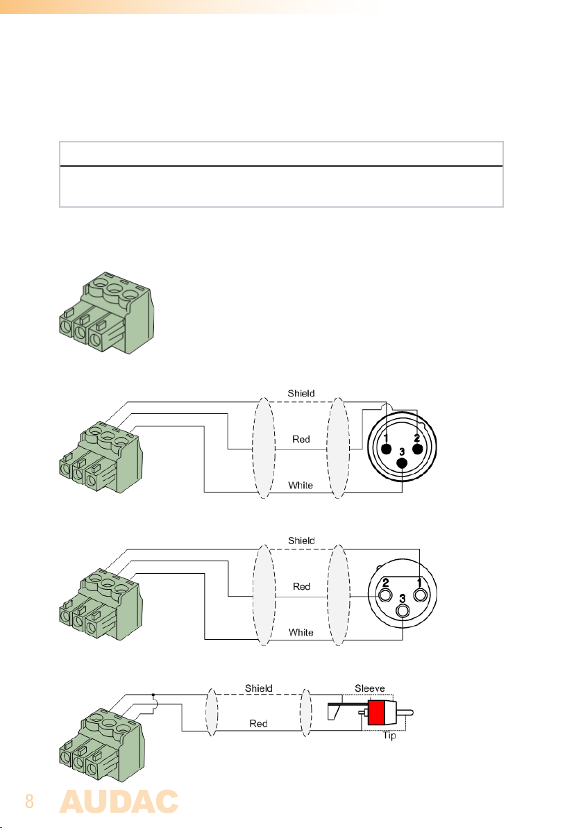
The in- and output connections for AUDAC audio equipment are performed
corresponding to international wiring standards for professional audio equipment.
3-Pin terminal block:
For balanced in & output connections
Left: Signal - (XLR Pin 3)
Center: Signal + (XLR Pin 2)
Right: Ground (XLR Pin 1)
For balanced line output connections (playback):
For balanced line input connections (recording):
For unbalanced line in & output connections:
Page 9
9
Chapter 2
Overview MMP40
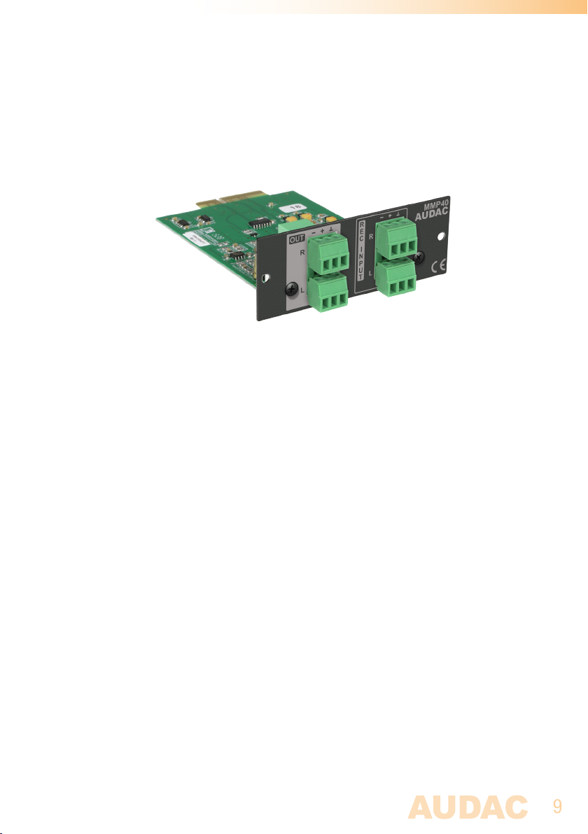
The MMP40 is a SourceCon™ compatible module featuring an (internal) board-edge
connector which carries all signals for getting it connected to any supporting main unit.
All external in & output connections shall be made using the available connectors on
the panel.
1) Balanced stereo line output:
The balanced stereo line output is implemented using two 3-pin terminal block
connectors. The audio output available on this connector allows it to be fed to any
amplifier or pre-amplifier.
2) Balanced stereo record input:
The balanced stereo line input (recording input) is implemented using two 3-pin terminal
block connectors. The line level audio signal coming from the audio source or preamplifier shall be connected to this connector, allowing it being recorded.
Page 10
10
Chapter 3
Using the MMP40
Since the MMP40 is a SourceCon™ module, it can be combined with a variation of
supporting main units. The operation and configuration interface might be different of
the unit where installed, however the offered functionality is identical. Some devices
will support control and configuration through a front panel graphical control interface
on a display, while others are also supporting web-control.
This manual describes the control configuration possibilities using front panel control. For
applications where more control possibilities are offered, check the instruction manual
of the used main device for more instructions.
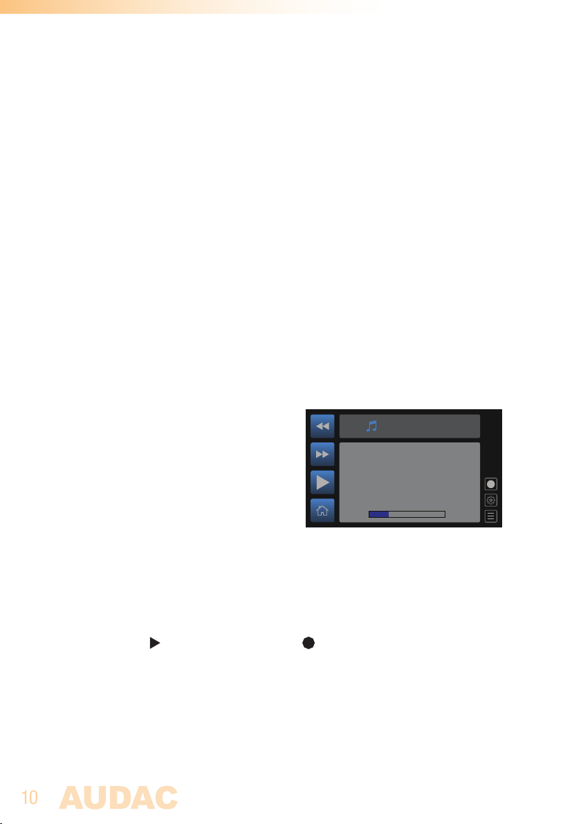
Module screen
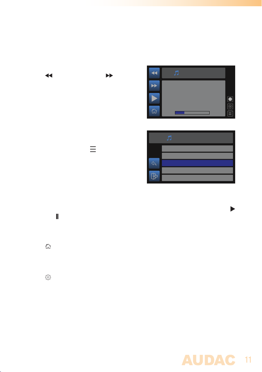
The module screen of the MMP40 gives an
overview of the current operation mode and can
be switched between media player mode and
media recorder mode. In media player mode,
the track position, track name and album cover
(if available) will be displayed on this screen.
In media recorder mode, the filesize of the
recorded track and length of the recorded track
are indicated.
The left section of the module screen includes 4 quick buttons which can be controlled
through the tactile buttons on the left screen side.
Switching between record or playback mode is done through rotating the selection dial
and selecting the (switch to media player) or (switch to media recorder) icons.
Track name
Media Player
0:30
1:59
Page 11
11
Media player mode
Track selection:
The playing track can be selected by pressing
the (previous track) and (next track)
buttons. When selected, the first next supported
Track name
track will be selected and start playing. When
using this function, track browsing throughout
the entire inserted media carrier can be done,
including all sub-folders.
Track browsing:
Browsing through the folders of the inserted
media carrier can be done by using the rotary
dial and selecting the (browse) icon. The
media player browsing menu will be indicated
and browsing through the media files is done
by turning the function dial. The currently
highlighted file can be selected by pressing the
DINGDONG.MP3
ALARM.MP3
ADVERTISEMENT.MP3
TRACK1.MP3
TRACK2.MP3
selection dial.
Play / pause:
Toggling between play and pause is done by pressing the play/pause button with
(play) or (pause) symbols. Depending of the current mode, the displayed symbol on
the icon will toggle.
Media Player
0:30
Media Player
Select le from SD
1:59
Home:
The (home) button gets you back to the main screen of the device where the MMP40
is installed to.
Settings:
The (settings) button can be selected through rotating the selection dial until the icon
is highlighted and pressing it. This button gets you to the media player settings menu
of the MMP40 where all configurations can be made. (it also includes various recording
settings, which can only be accessed when switched to recorder mode)
Page 12
12
Media player settings
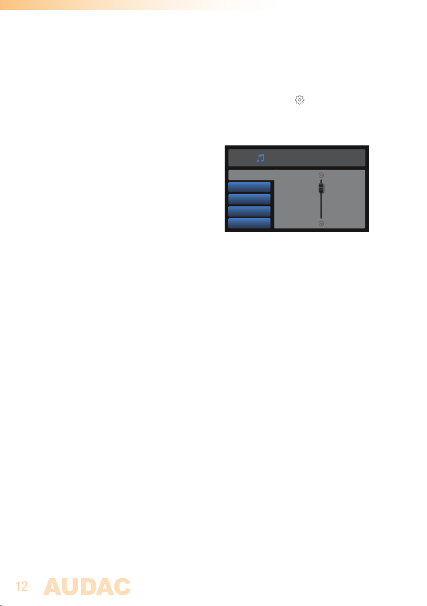
The player settings menu for MMP40 is loaded when pressing the (settings) button
in player mode.
Output gain:
The gain can be adjusted within a range of +8
dB and -92 dB, allowing optimalization of the
output level according to the input sensitivity of
the connected amplifier or pre-amplifier. For
adjusting the output gain, rotate the function
dial until ‘Gain’ is highlighted and press it for
proceeding to the gain settings. The level can
Output gain
Shue
Repeat mode
Play mode
Back
be adjusted by rotating clockwise (volume up)
or counter-clockwise (volume down). Press the
rotary dial for confirming the currently set output
level.
Shuffle:
Random play mode (shuffle) can be switched On and Off. When switched On, all tracks
will be played in a randomized sequence. The MMP40 will select between all the tracks
available on the inserted media carrier including all sub-folders.
Toggle the shuffle mode by highlighting ‘Shuffle’ (navigate through rotary dial) and
pressing the rotary dial.
MMP40 SETTINGS
0dB
Repeat mode:
The repeat mode can be switched between ‘Off’, ‘Repeat all’, ‘Repeat one’ and ‘Repeat
folder’. When ‘Repeat all’ is enabled, all tracks on the inserted media carrier will be
played in sequential order and when the last track is played, it will restart automatically
with the first track. When selected ‘Repeat one’, the currently selected track will
continuously play in an endless loop. When selected ‘Repeat folder’, all tracks in the
same folder of the currently playing track will be played in a sequential order and when
the latest track inside this folder is played, it will automatically restart with the first
track in this folder.
Toggle between the various repeat modes by highlighting ‘Repeat mode’ (navigate through
rotary dial) and pressing the rotary dial.
Page 13
13
Play mode:
The play mode can be selected between ‘Single play’ and ‘Continuous play’. In
‘Continuous play’ mode, the next track will automatically start playing when the current
track is finished. In ‘Single play’ mode, the player stops playing, waiting for a ‘Play’
command (press the Play button) before playing the next track.
In applications where the device is used for music playback, usually the ‘Continuous play’
will be used, while in other situations such as educational purposes, houses of worships
or gym’s the ‘Single play’ mode can provide great user convenience.
Media recorder mode
Start recording:
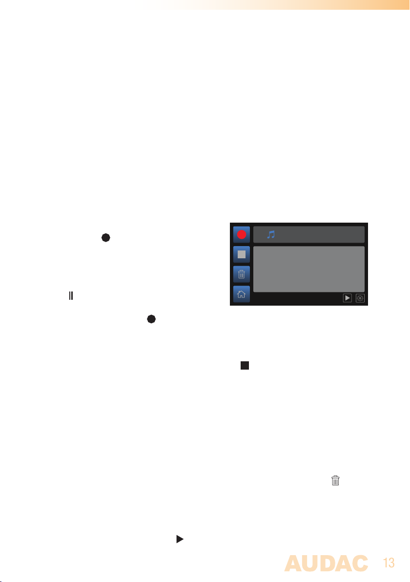
Recording of audio tracks can be started by
pressing the button. The display will indicate
the filesize (in kB) and length (in minutes and
seconds) of the current recording.
Media Recorder
Track name
224 kB recorded
While recording, the upper button will change
to (pause) allowing to pause the current
recording. When resuming recording after
paused (press again the record button) the
recording will continue within the same track.
Stop recording:
The recording can be stopped through pressing the (stop) button. When pressed, the
recording will be stopped and the file will be closed, making it unable to resume the
recording within the same track.
When restarting the recording after stop, the audio recording will be stored as an
individual file. When the filename is not changed in between various recordings (to be
done in recording settings menu), the subsequent recordings will be indicated with a
number (e.g. recording(2).mp3) in the stored filename.
Delete recording:
While recording, the current recording can be removed through pressing the (delete)
button. Note that deleted files are permanently removed and cannot be recalled
afterwards.
Pre-listening recording:
Once stopped the recording, the (play) button becomes available, allowing to prelisten the last made recording.
0:30
Page 14
14
Media recorder settings
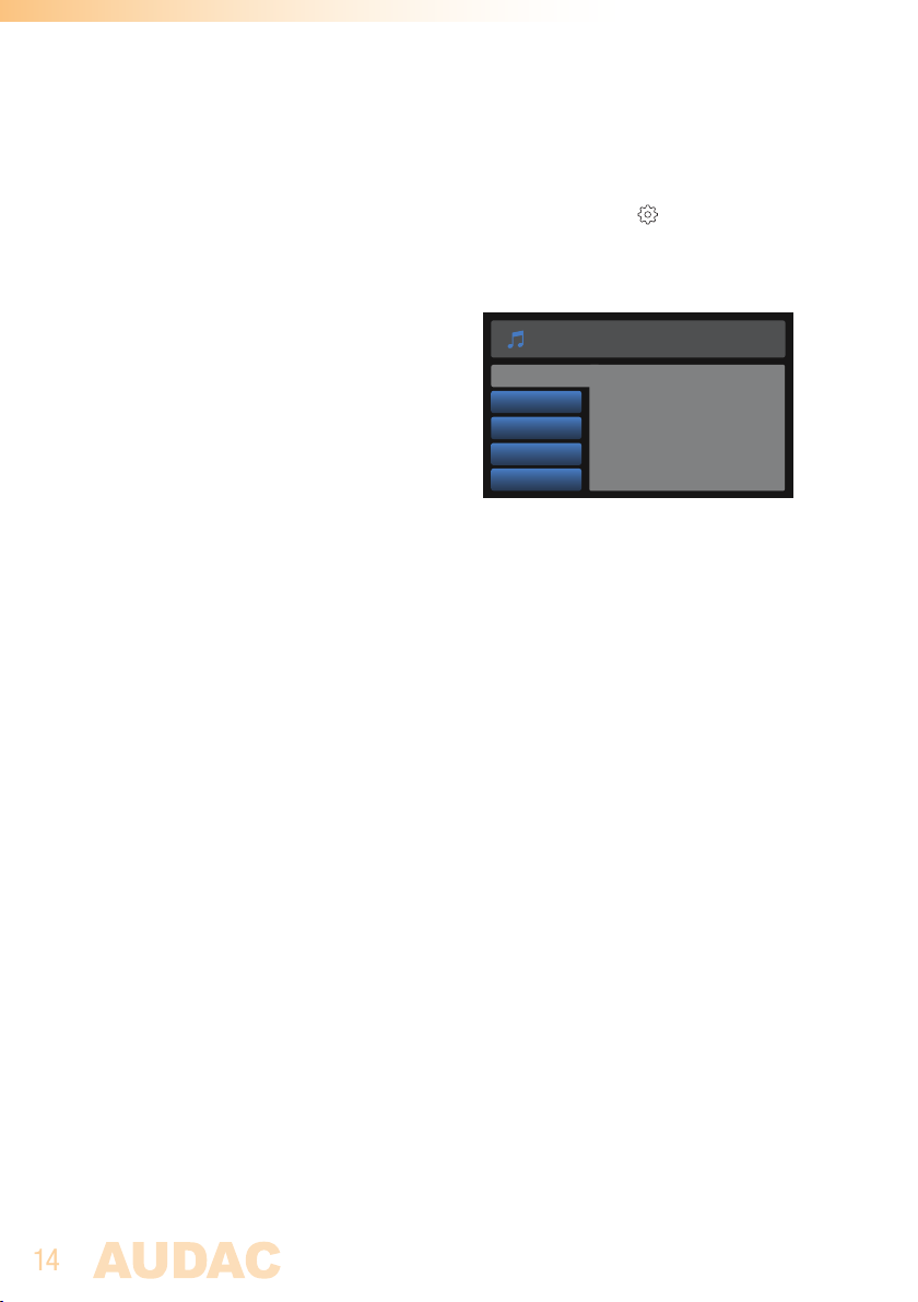
The recorder settings menu for MMP40 is loaded when pressing the (settings) button
in recorder mode.
Filename:
The filename of the recorded tracks can be
configured in this screen. When selected, a
screen with keyboard overview allows to enter
the filename through using the rotary selection
dial. When entered, select ‘OK’ to confirm the
currently entered track name. ‘Delete’ removes
the latest entered character, while ‘Cancel’
brings you back to the settings overview screen
without any applied changes.
When making multiple recordings in a row, each audio recording will be stored as an
individual file (when the recording was stopped). When the filename is not changed in
between various recordings, the subsequent recordings will be indicated with a number
(e.g. recording(2).mp3) in the stored filename.
Filetype:
The filetype of the recordings can be selected between MP3, OGG Vorbis and Wav. Toggle
between the various recording filetypes by highlighting ‘Filetype’ (navigate through rotary
dial) and pressing the rotary dial.
MMP40 RECORDER SETTINGS
Filename
Filetype
Mono/stereo
MP3
OGG Vorbis
Mono/stereo:
The recording for MP3 filetypes can be switched in various types of mono / stereo
modes, including ‘Joint stereo’, ‘Dual stereo’, ‘ Mono (left input)’ and ‘Mono mix’.
Toggle between various recording modes by highlighting ‘Mono / stereo’ and (navigate
through rotary dial) and pressing the rotary dial.
Using ‘Joint stereo’ mode, the similarities and differences between both left and right
channels are individually encoded. This improves the compression efficiency at a slight
loss of separation.
Using ‘Dual stereo’, both left and right channels are individually encoded as completely
separate signals. Each channel uses half of the available bitrate, for example by a 128
kbit recording, each channel would take 64 kbit.
Page 15

15
Using ‘Mono (left input)’, only the signal available on the left recording input will be
recorded as a single (mono) audio signal.
Using ‘Mono mix’, both left and right signal inputs will be summed to a mono signal,
which will be recorded as a single (mono) audio signal.
MP3:
The MP3 recording settings can be selected between ‘Variable bitrate’ and ‘Constant
bitrate’. In constant bit rate mode, a fixed bitrate is used for the entire track resulting
in consistent and predictable file sizes. In variable bitrate mode, the bitrate is adapted
according to the complexity of the audio. For simple passages, the system automatically
turns the bitrate down, saving valuable data bits while retaining audio quality. During more
complex passages, the system automatically turns the bitrate up, using more databits to
retain the same level of audio quality. In general, the variable bitrate gives better results
in terms of audio quality, while the constant bitrate is better for compatibility (mainly
with older systems).
The bitrate for the audio recording can be selected between 64 kbps, 96 kbps, 128
kbps, 192 kbps, 256 kbps and 320 kbps. A bitrate of 192 kbps is generally accepted
as good-quality, while a 256 kbps recording corresponds with CD quality. For constant
bitrate recordings, the selected bitrate is constant throughout the entire track, while for
variable bitrate recordings the nominal bitrate is defined, which could be influenced by
the complexity and detail of the audio.
OGG Vorbis:
For OGG Vorbis recordings, the quality settings can be selected by a number from ‘0’
to ‘9’, whereby ‘0’ corresponds with a nominal bitrate of 64 kbps and ‘9’ corresponds
with a nominal bitrate if 320 kbps. Starting from ‘6’ (192 kbps) the recording is generally
accepted as a good-quality recording, while ‘8’ (256 kbps) corresponds with CD quality.
An OGG recording provides the same quality for a lower filesize, compared to MP3.
WAV:
For WAV recodings, the sampling rate can be selected between 8 kHz, 16 kHz, 24 kHz, 32
kHz and 48 kHz with a fixed bit depth of 16 bits per sample. Depending on the application,
the suitable sample rate can be selected. For high-quality music recordings, it is
recommended to always select the 48 kHz sample rate, while for voice announcements
or other spoken message recordings, lower sample rates can be sufficient.
Page 16
16
Chapter 4
Installing the MMP40
CAUTION
Before installing the MMP40 to any SourceCon™ compatible device,
make sure the power is switched off. Malfunctions or electrical shocks
may occur otherwise.
Step 1:
Make sure that the slot whereto the module should be installed is open and ready for
installation. Depending of the main unit, some module slots will be covered by blind
panels when delivered. The corresponding blind panels should be removed by releasing
the screws on both ends.
Step 2:
Before removing the modules from their protective bag, we recommend touching a
grounded metal chassis (or any other grounded point) to prevent electrostatic discharges
affecting the sensitive electronic components. It is recommended to always hold the
module card by the metal connection panel and avoid touching of the components on
the circuit board directly.
Step 3:
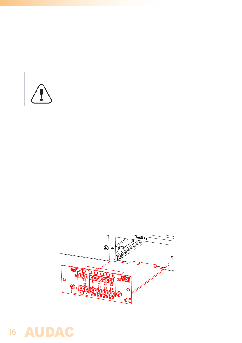
Align both edges of the module with the guide rails inside the slot and carefully insert
the module into the slot. It should slide into the slot without any considerable resistance
when well positioned into the guide rail.
Page 17
17
Step 4:
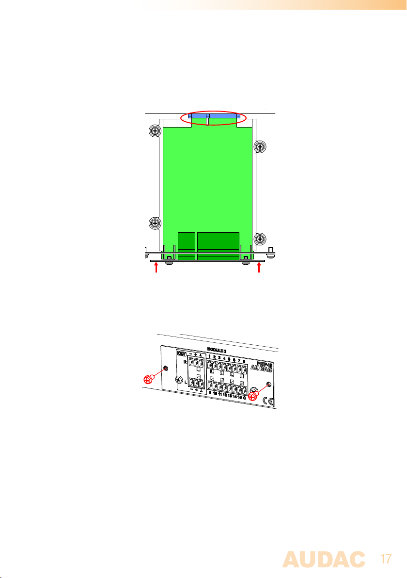
Some resistance might occur when the module’s board edge connector reaches the
connection counterpart on the main board. Gently push the module all the way into the
slot to ensure that the contacts are correctly inserted. The module is well inserted when
its connection panel touches the metal chassis of the main device where inserted to.
Step 5:
Fasten the module into the slot using the included screws. Be aware that damage or
malfunctions may occur if the module is not correctly fastened.
Step 6:
Once the module correctly installed, the system can be powered-on and the module
functionality will be automatically discovered.
Page 18

18
Chapter 5
Technical specifications
Connection SourceCon™ interface card slot
Input Balanced stereo line input
(2 x 3-pin Euro Terminal Block ~ 3.81 mm)
Output Balanced stereo line output
(2 x 3-pin Euro Terminal Block ~ 3.81 mm)
Output level +8 dB ~ -91 dB
(Software configurable)
Supported filetypes playback MP3 V1.0, V2.0, V2.5
Ogg vorbis
MPEG4/2 AAC-LC+PNS
HE-AAC v2 (Level 3), SBR+PS
WMA 4.0/4.1/7/8/9
WAV (PCM + IMA ADPCM);
Compatible media playback USB Flash drive / HDD (external)
Compatible filesystems FAT16/FAT32
Supported media carrier capacity Max 8 TB (FAT32)
Signal/noise 94 dB
THD+N < 0.07%
Frequency response 20 Hz - 20 kHz
Crosstalk 80 dB
Power consumption 1.0 Watt
Dimensions (W x H x D) 87 x 34.5 x 114 mm
Weight 0.075 Kg
Packaging Carton box
Shipping weight & Volume 1.08 Kg - 0.028 Cbm
Compatible devices XMP44 Modular audio system
Page 19

19
Notes
Page 20

20
Notes
 Loading...