

Page 1

FMP40
User Manual
www.audac.eu
Page 2

2
ADDITIONAL INFORMATION
This manual is put together with much care, and is as complete as could be on the
publication date. However, updates on the specifications, functionality or software
may have occurred since publication. To obtain the latest version of both manual and
software, please visit the Audac website @ www.audac.eu.
Page 3

3
Index
Introduction 5
Precautions 6
Safety requirements 6
Caution servicing 7
EC Declaration of Conformity 7
Waste of Electrical and Electronic Equipment (WEEE) 7
Chapter 1: Connections and connectors 8
Connection standards 8
Chapter 2: Overview FMP40 9
Chapter 3: Using the FMP40 11
Module screen 11
Settings screen 12
Chapter 4: Installing the FMP40 17
Chapter 5: Additional information 19
Technical specifications 19
Notes 20
Page 4

4
Page 5

5
Introduction
SourceCon™ voice file media player module
The FMP40 is a professional voice file media player featuring SourceCon™ modular
technology. This unique technology guarantees true plug & play implementation to any
compatible device. When inserted to a supporting slot, the module is instantly installed,
discovered and ready for operation without requiring any additional internal wiring or
complex configuration.
The FMP40 features 15 contact inputs which can be used for triggering music / voice file
messages stored on various types of media carriers. Media playback from USB storage
drives is possible when inserted to the controlling device, while an internal Micro SD
card slot safely locks the carrier inside for applications where frequent media changes
are not required. Media playback is supported in MP3, WMA, WAV, FLAC, OGG and AAC
filetypes with numerous supported bitrates.
Each contact is individually configurable, offering selection for the triggered media file
and normal open (NO) or normal closed (NC) contact operation. The playback mode
can be selected between pulse trigger (play complete track) or stop on release. Event
triggering allows triggering at pre-defined moments. Other settings such as priority
level assignment and repeat are making the FMP40 a complete and versatile solution
for any application requiring voice file playback, ranging from advertisements and
announcements to emergency calls.
All contact inputs are implemented using multipin terminal block connectors, while the
balanced stereo line output is implemented using two 3-pin terminal block connections.
Page 6

6
Precautions
READ FOLLOWING INSTRUCTIONS FOR YOUR OWN SAFETY
• ALWAYS KEEP THESE INSTRUCTIONS FOR FUTURE REFERENCE. NEVER
THROW THEM AWAY
• ALWAYS HANDLE THIS UNIT WITH CARE
• HEED ALL WARNINGS AND FOLLOW ALL INSTRUCTIONS
• AVOID ELECTROSTATIC DISCHARGE BY TOUCHING GROUNDED POINT BEFORE
REMOVING THE MODULES FROM THEIR PROTECTIVE BAG
• AVOID TOUCHING OF THE COMPONENTS ON THE CIRCUIT BOARD DIRECTLY
• NEVER EXPOSE THIS EQUIPMENT TO RAIN, MOISTURE, ANY DRIPPING OR
SPLASHING LIQUID. NEVER PLACE AN OBJECT FILLED WITH LIQUID ON TOP
OF THIS DEVICE
• DO NOT INSTALL THIS UNIT NEAR ANY HEAT SOURCES SUCH AS RADIATORS
OR OTHER APPARATUS THAT PRODUCE HEAT
• DO NOT PLACE THIS UNIT IN ENVIRONMENTS WITH A HIGH LEVEL OF DUST,
HEAT, MOISTURE OR VIBRATION
• THIS UNIT IS DEVELOPED FOR INDOOR USE ONLY. DO NOT USE IT OUTDOORS
• ONLY USE ATTACHMENTS & ACCESSORIES SPECIFIED BY THE
MANUFACTURER.
• UNPLUG THIS APPARATUS DURING LIGHTNING STORMS OR WHEN UNUSED
FOR LONG PERIODS OF TIME
• CAREFULLY CHECK THE UNIT’S CONDITION AFTER UNPACKING.
IF THERE IS ANY DAMAGE TO THE CARTON BOX OR THE UNIT ITSELF,
INFORM YOUR VENDOR IMMEDIATELY.
• ONLY CONNECT THIS UNIT TO A MAINS SOCKET OUTLET WITH PROTECTIVE
EARTHING CONNECTION
• THE INSTALLATION, CONNECTION AND CONFIGURATION OF THE DEVICE
SHOULD BE DONE BY QUALIFIED TECHNICIANS
Page 7
7
CAUTION - SERVICING
This product contains no user serviceable parts. Refer all servicing
to qualified service personnel. Do not perform any servicing
(unless you are qualified to do so.)
EC DECLARATION OF CONFORMITY
This product conforms to all the essential requirements and further
relevant specifications described in following directives: 2014/30/
EU (EMC) and 2014/35/EU (LVD)
WASTE ELECTRICAL AND ELECTRONIC EQUIPMENT (WEEE)
The WEEE marking indicates that this product should not be
disposed with regular household waste at the end of its product
life. This regulation is created to protect both the environment
and human health.
This product is developed and manufactured with high quality
materials and components which can be recycled and/or reused.
Please dispose of this product at your local collection point or
recycling centre for electrical and electronic waste. Do this to
make sure that the product is recycled in an environmental friendly
way, and help to protect the environment in which we all live.
CAUTION
The symbols shown are internationally recognized symbols that warn about potentional
hazards of electrical products. The lightning flash with arrowpoint in an equilateral
triangle means that the unit contains dangerous voltages. The exclamation point in
an equilateral triangle indicates that it is necessary for the user to refer to the users
manual.
These symbols warn that there are no user serviceable parts inside the unit. Do not
open the unit. Do not attempt to service the unit yourself. Refer all servicing to qualified
personnel. Opening the chassis for any reason will void the manufacturer’s warranty.
Do not get the unit wet. If liquid is spilled on the unit, shut it off immediately and take
it to a dealer for service. Disconnect the unit during storms to prevent damage.
Page 8
8
Chapter 1
Connections and connectors
CONNECTION STANDARDS
The in- and output connections for AUDAC audio equipment are performed
corresponding to international wiring standards for professional audio equipment.
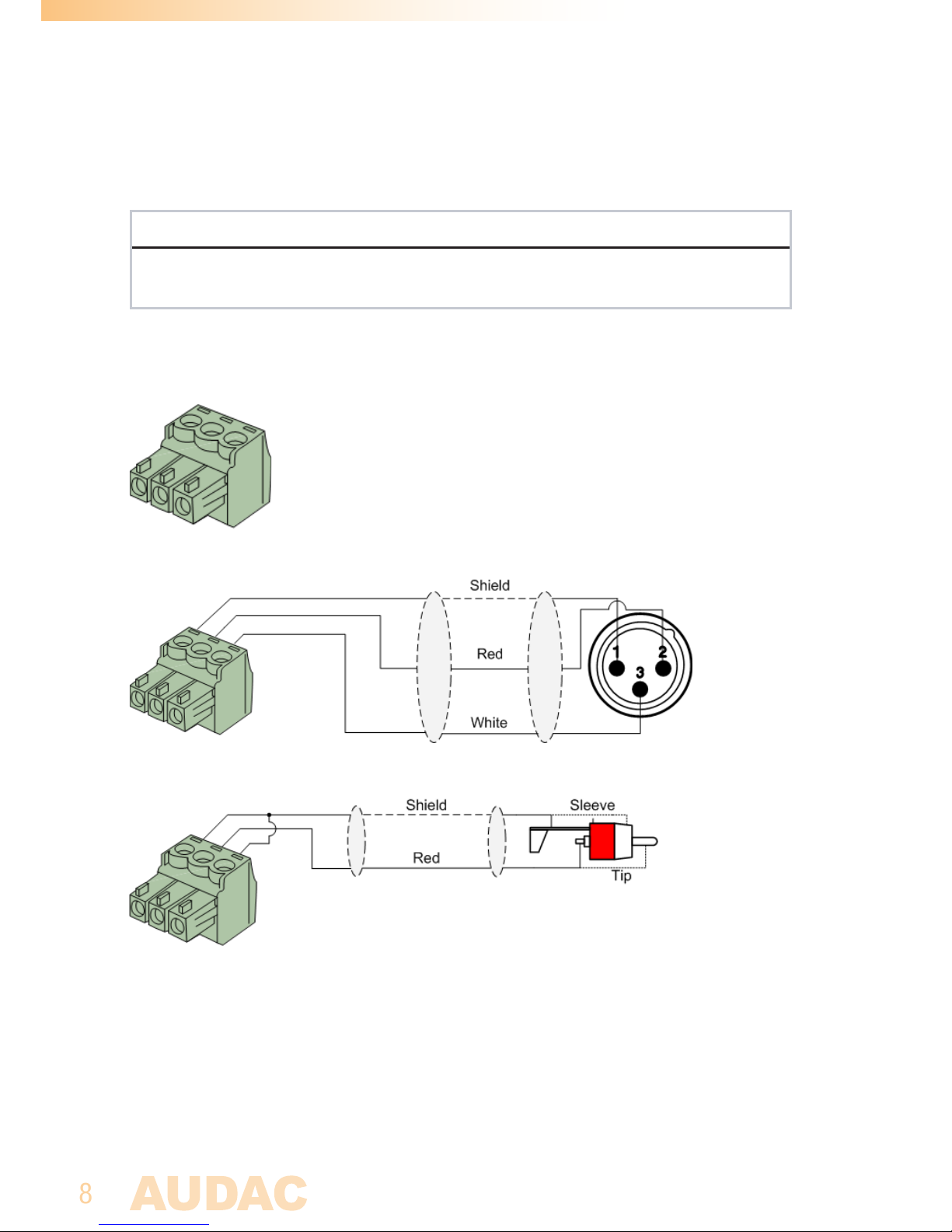
3-Pin terminal block:
For balanced in & output connections
Left: Signal - (XLR Pin 3)
Center: Signal + (XLR Pin 2)
Right: Ground (XLR Pin 1)
For balanced line output connections:
For unbalanced line output connections:
Page 9
9
Chapter 2
Overview FMP40
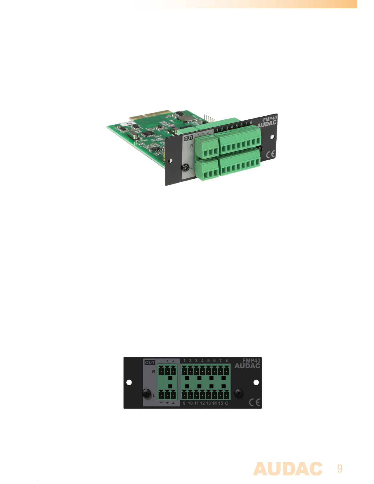
The FMP40 is a SourceCon™ compatible module featuring an (internal) board-edge
connector which carries all signals for getting it connected to any supporting main unit.
All external in & output connections shall be made using the available connectors on
the panel.
1) Balanced stereo line output:
The balanced stereo line output is implemented using two 3-pin terminal block
connectors. The audio output available on this connector allows it to be fed to any
amplifier or pre-amplifier.
2) Trigger contact inputs:
The 15 contact inputs are implemented through dual-row 8-pin terminal block
connectors. All of them are (software) configurable as NO (normal-open) or NC (normalclosed) contacts allowing connection for any type of external trigger (switch, relay, ... ).
The contacts pinout is indicated in the above image, with in the bottom right corner the
‘C’ (common) terminal.
Page 10
10
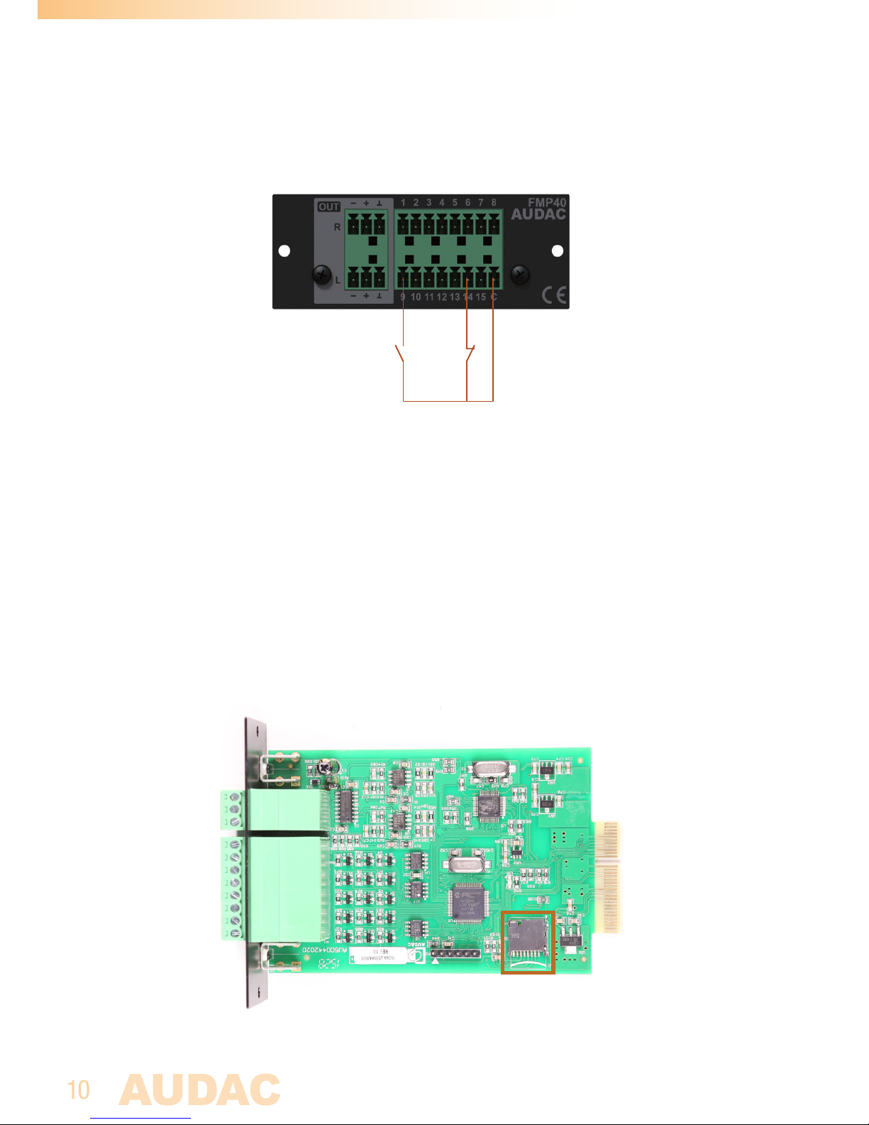
A connection between all contact inputs (1 to 15) and the ‘C’ (common) terminals shall
always be made, as indicated in the below diagram.
NO (Normal Open)
contact
NC (Normal Closed)
contact
Depending of the application, a selection of NO (normal-open) or NC (normal closed)
contacts can be made through software configuration. NO contacts can be triggered
by standard tact switches, while NC contacts offer the additional advantage that a wire
interruption is detected as a contact trigger (which often is a requirement for alarm or
emergency announcement systems).
3) Micro SD card slot:
The micro SD card slot (with pre-installed micro SD card) allows integrated installation
of the media carrier. When no frequent changes of announcements / alarms are required
(e.g. alarm & announcement systems) it is recommended for having the media carrier
internally installed avoiding removal by unauthorized users.
Micro SD card slot (indicated in orange square) on FMP40
Page 11
11
Chapter 3
Using the FMP40
Since the FMP40 is a SourceCon™ module, it can be combined with a variation of
supporting main units. The operation and configuration interface might be different of
the unit where installed, however the offered functionality is identical. Some devices
will support control and configuration through a front panel graphical control interface
on a display, while others are also supporting web-control.
This manual describes the control configuration possibilities using front panel control. For
applications where more control possibilities are offered, check the instruction manual
of the used main device for more instructions.
Module screen
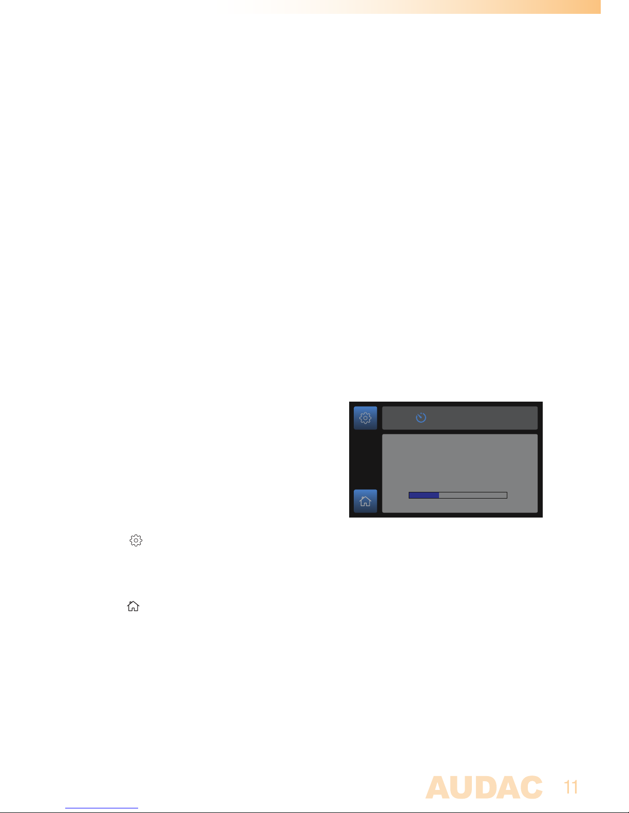
The module screen gives an overview of the
FMP40’s current operation mode. If any voice
file is triggered (track is playing), the currently
playing track name and progress will be
indicated on this screen.
Settings:
The (settings) button gets you to the settings menu of the FMP40 where all
cofigurations can be made.
Home:
The (home) button gets you back to the main screen of the device where the FMP40
is installed to.
File Player
Track name
0:30
1:59
Page 12
12
Settings screen
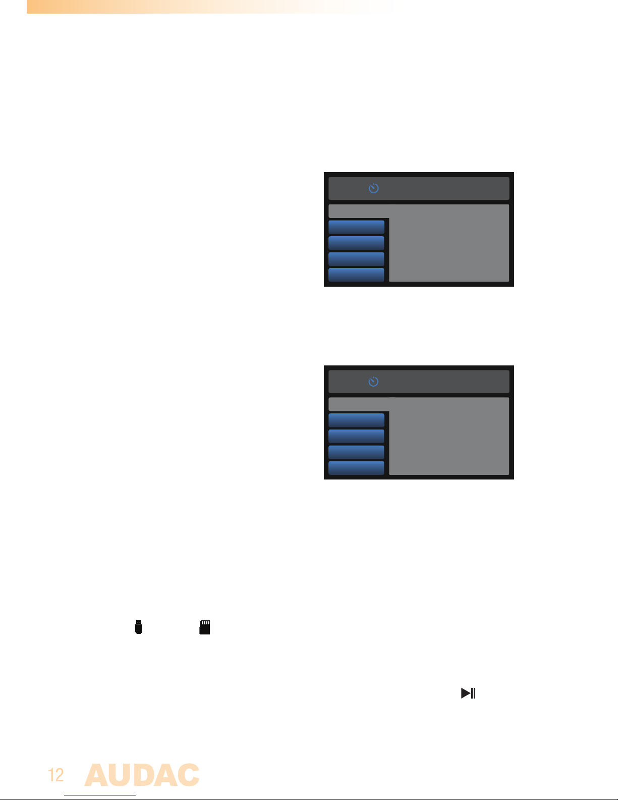
The settings screen allows configuration for all FMP40 settings.
Contacts:
The contacts menu gives an overview of all 15
contact inputs, allowing them to be switched
between Normal Open (NO) and Normal closed
(NC) configuration.
Switching between contacts is done by rotating
the function dial, while toggling between Normal
Open and Normal Closed is done by pressing the
function dial. To return back to the main settings
menu, select ‘BACK’ in the bottom right corner.
Triggers:
The triggers menu gives an overview of all
the triggers controlling voice files to play. A
maximum of 50 triggers can be configured by
a contact closure or a timed (pre-programmed)
event. When selecting the ‘Triggers’ option,
a screen allowing selection between all 50
triggers will be shown. Select the corresponding
trigger to proceed to the corresponding trigger
settings.
Trigger > Enable:
The ‘Enable’ option allows to enable or disable the selected trigger number. Press the
rotary dial for toggling between Enabled and Disabled.
Trigger > File:
The ‘File’ option allows selection of the voice file which starts playing when triggered.
Using the (USB) and (SD-card) knobs, switching between both media carriers is
done. When the media carrier is selected, an overview of the stored (supported) media
files is listed. The files for voice file triggering shall be located in a ‘\messages\’ folder on
the inserted carrier. Browsing between the media files is done by turning the function dial,
while the currently highlighted file can be pre-listened though pressing the button.
For selecting the currently highlighted media file, press the function dial for confirmation.
A single file (track) or a complete folder (located inside the ‘\messages\’ folder) can be
selected. When selected a folder, all contained files will play subsequently (when selected
the correstponding playmode)
FMP40 Settings
Contacts
1: Normal Open
2: Normal Closed
3: Normal Open
4: Normal Open
5: Normal Open
6: Normal Open
7: Normal Open
8: Normal Closed
Triggers
Copy
Delete
Factory reset
9: Normal Open
10: Normal Open
11: Normal Closed
12: Normal Open
13: Normal Open
14: Normal Open
15: Normal Open
BACK
Trigger1
Enable
Enabled
File
Contact
Time
Priority
Page 13
13
NOTE
All tracks (or folders including multiple tracks) shall be located the ‘\messages\ folder
on the inserted media carrier.
Trigger > Contact:
The ‘Contact’ option offers the possibility for assigning a contact input enabling the
selected trigger. A selection out of the 15 available contact inputs can be made. Browsing
between various contact inputs is done by turning the function dial, while selection is
done by pressing it for confirmation.
Trigger > Time:
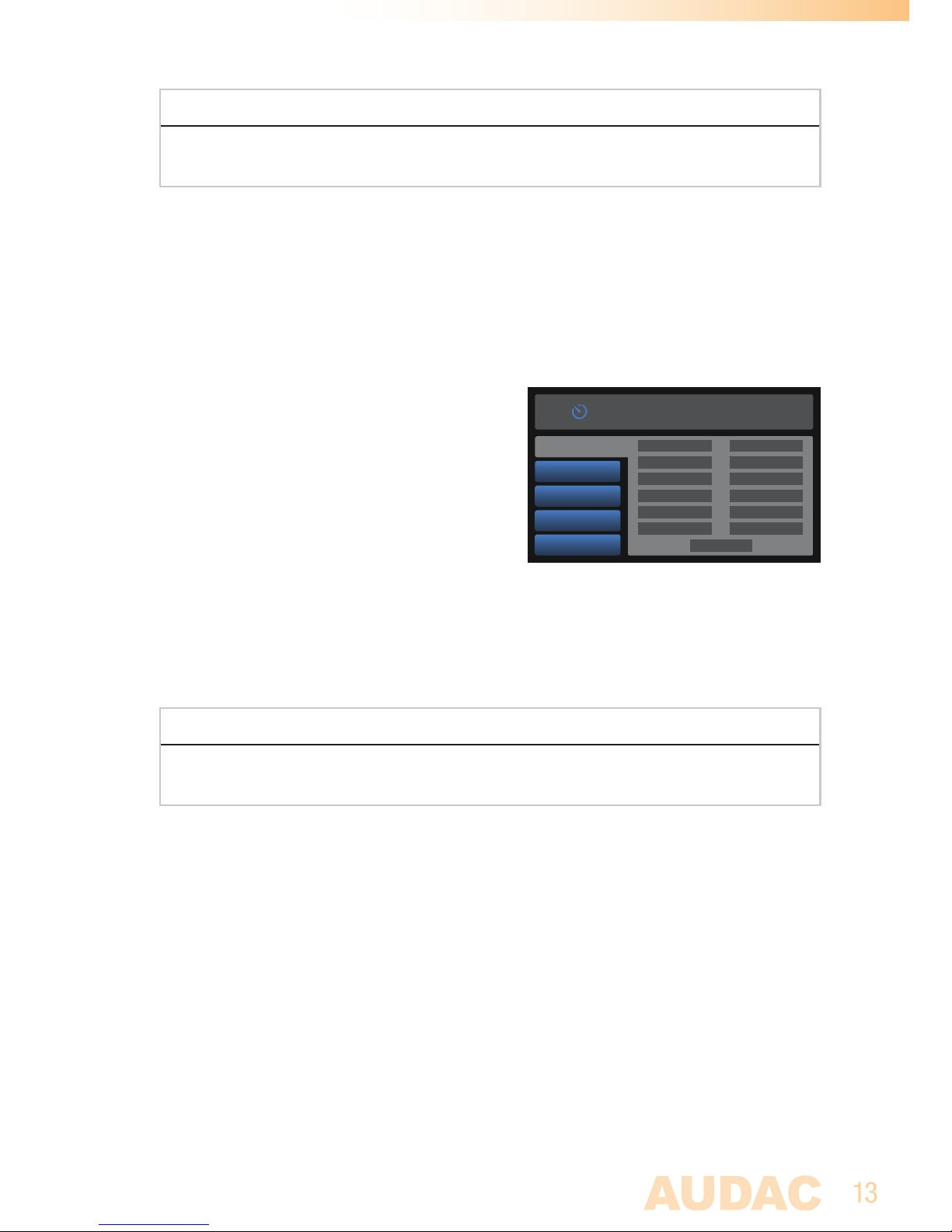
The ‘Time’ option offers the possibility for
assigning a pre-programmed (timed) event to
the selected trigger. This menu contains various
sub-divisions for Months, Days, Time, Start and
Stop.
The selected trigger will be enabled
whenever all entered parameters are true.
When more parameters are entered, each
entered parameter is an additional condition
which will require all conditions being true
before enabling the trigger.
NOTE
When using the timer triggering for announcements, make sure the playmode is
configured as ‘Repeat number of times’ (See chapter ‘Trigger > Playmode’)
- Month: Offers selection criteria for pre-programmed triggers being effective in certain
months only. All months are default configured as enabled (but can be disabled), meaning
the corresponding trigger will be effective for all months. Browsing through months is
done by turning the function dial, while selections are confirmed by pressing it. Select
‘Back’ to get up in the menu structure.
- Days: Offers selection criteria for pre-programmed triggers being effective on certain
days only. Possibilties are given for selection on ‘Days of Month’ (1 to 31) or ‘Days of
Week’ (Monday till Sunday). If both criteria are entered (‘Days of Month’ & ‘Days of week’),
the corresponding trigger will only be effective when both are true. Browse through days
by turning the function dial, while selections are confirmed by pressing the function dial.
Select ‘Back’ to get up in the menu structure.
DATE-TIME SETTINGS
Months
Days
Time
Start
Stop
January
February
March
April
May
June
July
August
September
October
November
December
Back
Page 14
14
- Time: Offers selection criteria for the exact time (Hours & Minutes) when the preprogrammed trigger shall be effective.
- Start / Stop: Gives the possibity for entering a specific start and/or stop date for the
time trigger. When enabled, the selected trigger will only be effective if the current date
is between the configured start and stop date. Toggling between enabled, disabled
and the actual date configuration (if enabled) is done by turning the function dial, while
pressing confirms and proceeds to the next step.
- Clear: Clears all the currently made settings for the selected trigger’s time settings.
NOTE
For time keeping, the main unit whereto installed the FMP40 shall get synchronization
from a time server. When internet access is available, an internet timeserver will
guarantee accurate synchronization of the system according to GMT. In case your
system is restricted from access to internet, an internal time server on your LAN
network should get assigned offering synchronization to the system.
Trigger > Priority:
The ‘Priority’ option allows assignment of a priority levels for the selected trigger. The
priority level can be selected within a range of 1 to 50, having the lowest (1) number the
highest level of priority. When multiple triggers are simultaneous effective, the trigger with
highest priority (lowest number) will interrupt the others. When two triggers with identical
priority are effective, the first activated one will remain active. Browsing between priority
levels is done by turning the function dial, while pressing it confirms the current selection.
Trigger > Playmode:
The ‘Playmode’ option offers various playmode selection possibilities for the currently
selected trigger, which are selectable between:
- Repeat file while trigger active: Infinitely repeats the configured file while trigger is
active (contact activated) and instantly stops playing once released. (contact triggering)
- Repeat folder while trigger active: Sequentially plays all tracks in the selected
folder (if a folder is selected) while trigger is active (contact activated) and instantly
stops playing once released. Once released and re-triggered, playback will start again
from the beginning of the first track. (contact triggering)
- Repeat number of times: Repeats the configured file for the selected number of times
when momentary triggered (timer and contact triggering). When momentary triggered
by contact, trigger shall remain active for at least 5 ms.
Page 15
15
- Repeat number of times while trigger active: Repeats the configured file for the
selected number of times while trigger is active (contact activated) and instantly stops
playing once released. (contact triggering)
- Repeat all while trigger active: Sequentially plays all tracks on the selected media
drive while trigger is active (contact activated) and instantly stops playing once released.
The first track to be played shall be configurred and once released and re-triggered,
playback will start again from this track. (contact triggering)
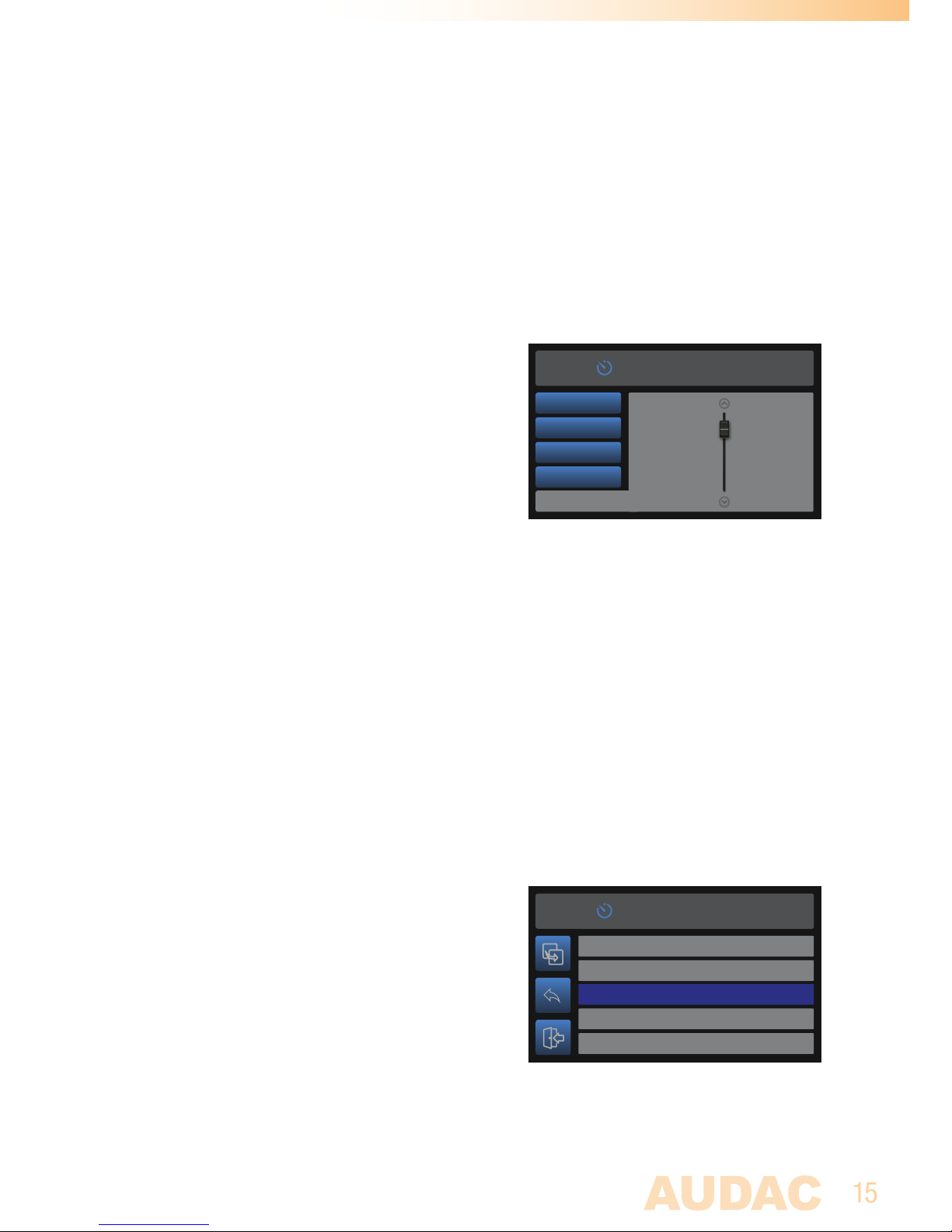
Trigger > Gain:
The gain (output level) for each trigger can
adjusted within a range of +8 dB and -92 dB,
allowing various situations with different output
levels (e.g. an emergency alarm with higher
volume than general announcements. The level
can be adjusted by rotating the function dial
clockwise (tuning up) or counter-clockwise
(tuning down). Press it for confirming the current
selection.
Trigger > Name:
Custom naming allows keeping a clear overview of all configured triggers. Naming with
a maximum of 10 characters can be given to each trigger. Character browsing is done by
turning the function dial while the current selection (highlighted) is confirmed by pressing.
Default or configured naming can be removed by selecting the ‘Delete’ option, while
‘Save’ confirms the current naming and gets you back to the trigger menu.
Trigger > Delete:
Delete removes all the curently made trigger settings, and sets everything (for this trigger
only) back to factory defaults.
Copy:
The copy menu allows copying of media files
from the USB media carrier (inserted to the front
panel of the supported main unit) to the internal
media carrier (Micro SD card) of the FMP40.
When no frequent changes of announcements /
alarms are required (e.g. alarm & announcement
systems) it is recommended to have the files
stored on the internal media carrier, avoiding
failures due to removal by unauthorized users.
Trigger 1
0dB
Time
Priority
Playmode
Gain
Contact
Select file from SD
DINGDONG.MP3
Copy to SD
ALARM.MP3
ADVERTISEMENT.MP3
TRACK1.MP3
TRACK2.MP3
Page 16

16
An overview of all availabe folders and files on the inserted USB drive is given. Browsing
through the media files is done by turning the function dial, while the currently highlighted
file can be copied by pressing the (copy) button.
Delete:
The delete menu allows removal of media files stored on the internal media carrier
(Micro SD card). An overview of the stored media files (on Micro SD card) is listed.
Browsing through the media files is done by turning the function dial, while the currently
highlighted file can be removed by pressing the (delete) button. Note that deleted files
are permanently removed and cannot be recalled afterwards.
Factory reset:
Factory reset will recall all settings to factory defaults and all previously made settings
and configurations will be lost. After selecting factory reset, a confirmation will be asked
whether all settings definitely need to be reset to factory defaults. When confirmed, all
settings will be lost.
Back:
Returning to the module screen is done by selecting ‘Back’.
Page 17
17
Chapter 4
Installing the FMP40
CAUTION
Before installing the FMP40 to any SourceCon™ compatible device,
make sure the power is switched off. Malfunctions or electrical shocks
may occur otherwise.
Step 1:
Make sure that the slot whereto the module should be installed is open and ready for
installation. Depending of the main unit, some module slots will be covered by blind
panels when delivered. The corresponding blind panels should be removed by releasing
the screws on both ends.
Step 2:
Before removing the modules from their protective bag, we recommend touching a
grounded metal chassis (or any other grounded point) to prevent electrostatic discharges
affecting the sensitive electronic components. It is recommended to always hold the
module card by the metal connection panel and avoid touching of the components on
the circuit board directly.
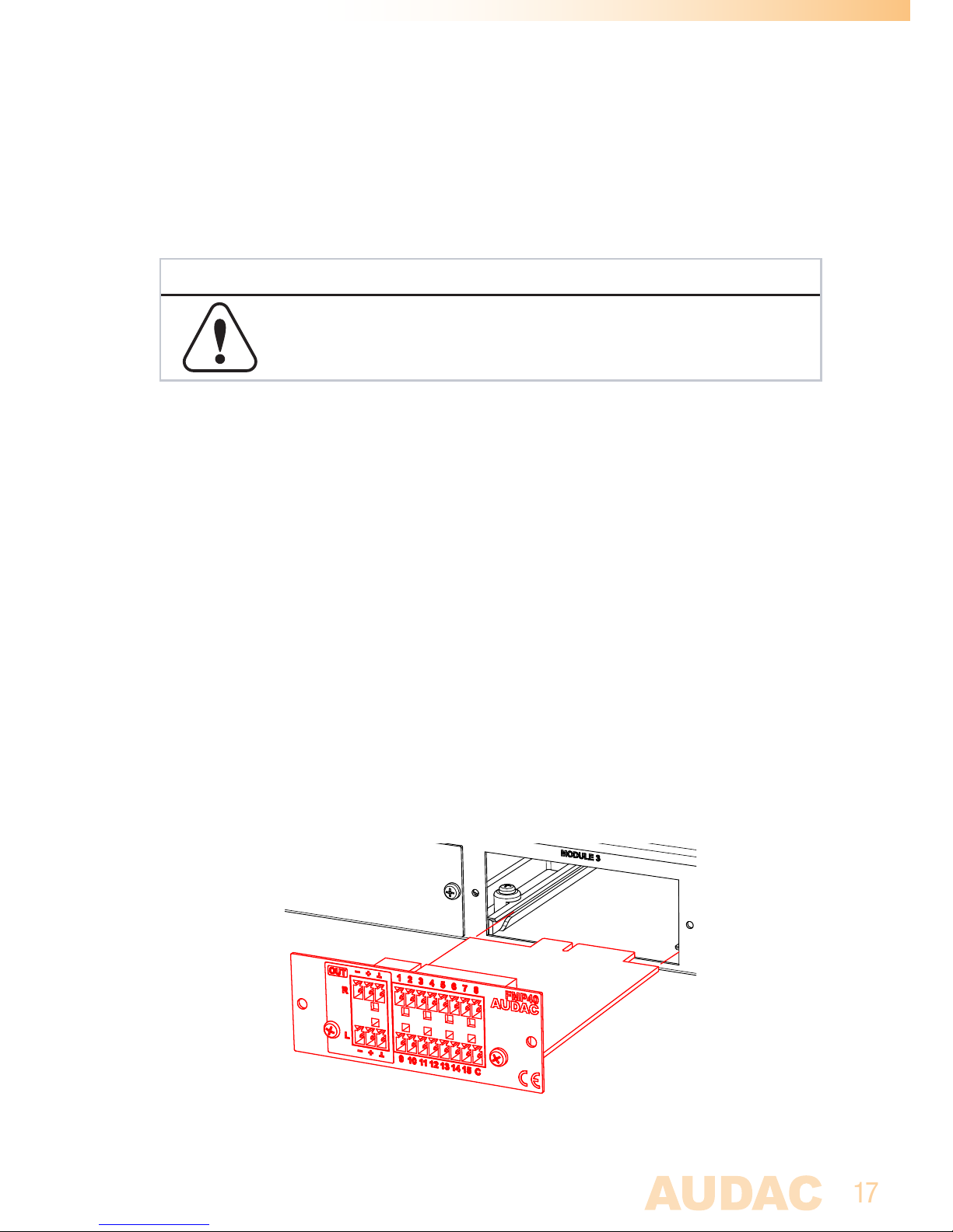
Step 3:
Align both edges of the module with the guide rails inside the slot and carefully insert
the module into the slot. It should slide into the slot without any considerable resistance
when well positioned into the guide rail.
Page 18
18
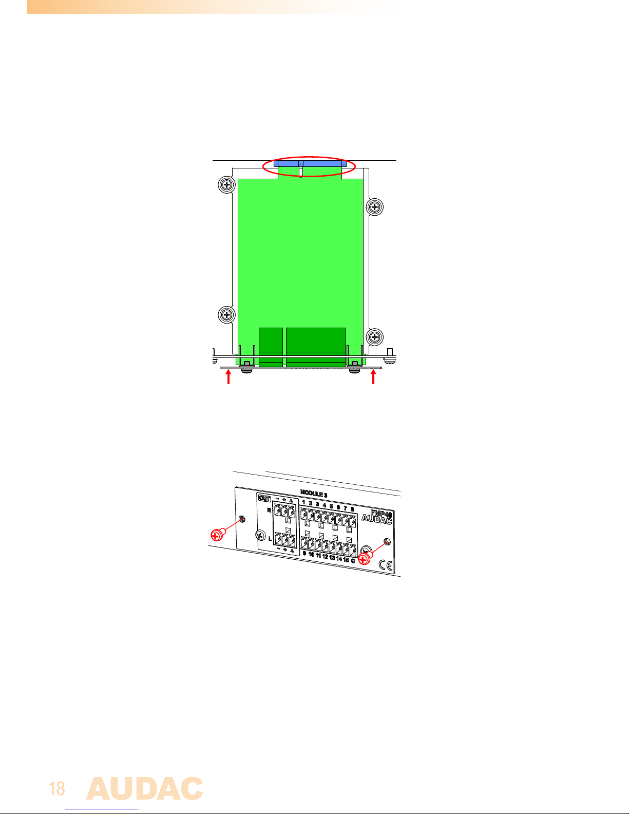
Step 4:
Some resistance might occur when the module’s board edge connector reaches the
connection counterpart on the main board. Gently push the module all the way into the
slot to ensure that the contacts are correctly inserted. The module is well inserted when
its connection panel touches the metal chassis of the main device where inserted to.
Step 5:
Fasten the module into the slot using the included screws. Be aware that damage or
malfunctions may occur if the module is not correctly fastened.
Step 6:
Once the module correctly installed, the system can be powered-on and the module
functionality will be automatically discovered.
Page 19

19
Chapter 5
Technical specifications
Connection SourceCon™ interface card slot
Input 15 trigger contact inputs (NO or NC)
(2 x 8-pin Euro Terminal Block ~ 3.81 mm)
Output Balanced stereo line output
(2 x 3-pin Euro Terminal Block ~ 3.81 mm)
Output level +8 dB ~ -91 dB
(Software configurable)
Compatible media playback USB Flash drive / HDD (external)
Micro SD card (internal)
Compatible filesystems FAT16/FAT32
Supported filetypes playback MP3 V1.0, V2.0, V2.5
Ogg vorbis
MPEG4/2 AAC-LC+PNS
HE-AAC v2 (Level 3), SBR+PS
WMA 4.0/4.1/7/8/9
WAV (PCM + IMA ADPCM);
General MIDI 1 / SP-MIDI
Signal/noise 94 dB
THD+N < 0.03%
Frequency response 20 Hz - 20 kHz
Crosstalk 80 dB
Power consumption 1.0 Watt
Dimensions (W x H x D) 87 x 34.5 x 114 mm
Weight 0.079 Kg
Packaging Carton box
Shipping weight & Volume 1.08 Kg - 0.028 Cbm
Compatible devices XMP44 Modular audio system
Accessories included Micro SD memory card (128 MB)
Page 20
20
Notes
 Loading...