

Page 1
User manual
SCP2xx
audac.eu
Page 2

ADDITIONAL INFORMATION
This manual is put together with much care, and is as complete as could be on the publication date.
However, updates on the specifications, functionality or software may have occurred since publication.
To obtain the latest version of both manual and software, please visit the Audac website @ audac.eu.
SCP2xx - User manual2
Page 3

Table of contents
Introduction 5
Compact dual-channel power amplifier � � � � � � � � � � � � � � � � � � � � � � � � � � � � � � � � � � � � � � � � � � � � � � � � � � � � � 5
Precautions 6
Chapter 1 8
Connections and connectors � � � � � � � � � � � � � � � � � � � � � � � � � � � � � � � � � � � � � � � � � � � � � � � � � � � � � � � � � � � � � � � 8
Chapter 2 9
Front panel overview � � � � � � � � � � � � � � � � � � � � � � � � � � � � � � � � � � � � � � � � � � � � � � � � � � � � � � � � � � � � � � � � � � � � � � � � 9
Rear panel overview � � � � � � � � � � � � � � � � � � � � � � � � � � � � � � � � � � � � � � � � � � � � � � � � � � � � � � � � � � � � � � � � � � � � � � � 10
Technical specifications 13
SCP2xx - User manual 3
Page 4

SCP2xx - User manual4
Page 5

Introduction
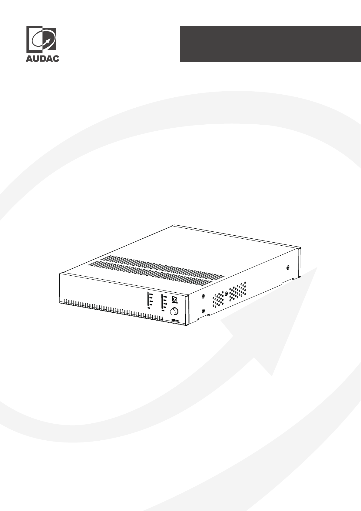
Compact dual-channel power amplifier
The SCP series is a range of extremely powerful compact dual-channel power amplifiers for
commercial use. These half 19” devices can be used in stereo low impedance or 70/100V bridge
mode. There are several different models to serve a wide range of applications with power ratings
that vary between 120W to 1000W in a half 19” rack space housing.
The compact and elegant design of the half 19” rack space enclosure allows for single installation in
a 10.5” equipment rack, or side-by-side (two devices) in a 19” equipment rack.
A connection to the WP2xx series input wall panels or volume controllers can be made via the RJ45
connectors on the back of the SCP.
Equipped with a standby mode switch, the SCP series will enter an energy-saving standby mode
after a period of inactivity. This feature together with the overall energy-efficient design makes the
SCP meet the high standards of the Energy Star certification.
When you combine the SCP series with a suitable pre-amplifier or wall-mounted input panel you
create a powerful and complete solutions for background music installations.
SCP2xx - User manual 5
Page 6

Precautions
READ FOLLOWING INSTRUCTIONS FOR YOUR OWN SAFETY
ALWAYS KEEP THESE INSTRUCTIONS. NEVER THROW THEM AWAY
ALWAYS HANDLE THIS UNIT WITH CARE
HEED ALL WARNINGS
FOLLOW ALL INSTRUCTIONS
NEVER EXPOSE THIS EQUIPMENT TO RAIN, MOISTURE, ANY DRIPPING OR SPLASHING LIQUID. AND NEVER PLACE AN
OBJECT FILLED WITH LIQUID ON TOP OF THIS DEVICE.
DO NOT PLACE THIS UNIT IN AN ENCLOSED ENVIRONMENT SUCH AS A BOOKSHELF OR CLOSET. ENSURE THERE IS
ADEQUATE VENTILATION TO COOL THE UNIT. DO NOT BLOCK THE VENTILATION OPENINGS.
DO NOT STICK ANY OBJECTS THROUGH THE VENTILATION OPENINGS.
DO NOT INSTALL THIS UNIT NEAR ANY HEAT SOURCES SUCH AS RADIATORS OR OTHER APPARATUS THAT PRODUCE HEAT
DO NOT PLACE THIS UNIT IN ENVIRONMENTS WHICH CONTAIN HIGH LEVELS OF DUST, HEAT, MOISTURE OR VIBRATION
THIS UNIT IS DEVELOPED FOR INDOOR USE ONLY. DO NOT USE IT OUTDOORS
PLACE THE UNIT ON A STABLE BASE OR MOUNT IT IN A STABLE RACK
ONLY USE ATTACHMENTS & ACCESSORIES SPECIFIED BY THE MANUFACTURER
UNPLUG THIS APPARATUS DURING LIGHTNING STORMS OR WHEN UNUSED FOR LONG PERIODS OF TIME
ONLY CONNECT THIS UNIT TO A MAINS SOCKET OUTLET WITH PROTECTIVE EARTHING CONNECTION
THE MAINS PLUG OR APPLIANCE COUPLER IS USED AS THE DISCONNECT DEVICE, SO THE DISCONNECT DEVICE SHALL BE
READILY OPERABLE
USE THE APPARATUS ONLY IN MODERATE CLIMATES
THIS DEVICE CAN BE SOLD IN ALL EU REGIONS
CAUTION
The symbols shown are internationally recognized symbols that warn about potential hazards of
electrical products. The lightning flash with arrow point in an equilateral triangle means that the
unit contains dangerous voltages. The exclamation point in an equilateral triangle indicates that it is
necessary for the user to refer to the users manual.
These symbols warn that there are no user serviceable parts inside the unit. Do not open the unit. Do not
attempt to service the unit yourself. Refer all servicing to qualified personnel. Opening the chassis for any
reason will void the manufacturer’s warranty. Do not get the unit wet. If liquid is spilled on the unit, shut it
off immediately and take it to a dealer for service. Disconnect the unit during storms to prevent damage.
SCP2xx - User manual6
Page 7
CAUTION SERVICING
This product contains no user serviceable parts. Refer all servicing to qualified service
personnel. Do not perform any servicing (unless you are qualified to)
EC DECLARATION OF CONFORMITY
This product conforms to all the essential requirements and further relevant specifications
described in following directives: 2014/30/EU (EMC) and 2014/35/EU (LVD). All related
standards are listed in a Declaration of Conformity (DoC), which can be found in the
products download section on the web-page audac.eu, our through scanning the QR
code on page 2 of this user manual.
WASTE ELECTRICAL AND ELECTRONIC EQUIPMENT WEEE
The WEEE marking indicates that this product should not be disposed with regular
household waste at the end of its life cycle. This regulation is created to prevent any
possible harm to the environment or human health.
This product is developed and manufactured with high quality materials and components
which can be recycled and/or reused. Please dispose this product at your local collection
point or recycling centre for electrical and electronic waste. This will make sure that it will be
recycled in an environmentally friendly manner, and will help to protect the environment
in which we all live.
POWER SUPPLY AND POWER CORD REQUIREMENTS
Power supply class I grounding requirements:
For protection from fault currents, the equipment shall be connected to a grounding terminal. Plug the
system power cord into an AC outlet that provides a ground connection. Substitute cords may not provide
adequate fault protection. Only use the power cord supplied with this product or an authorized/equivalent
replacement
SAFETY NOTICES:
DENMARK: Apparatets stikprop skal tilsluttes en stikkontakt med jord, som giver forbindelse til
stikproppens jord.
FINLAND: Laite on liitettävä suojakoskettimilla varustettuun pistorasiaan.
NORWAY: Apparatet må tilkoples jordet stikkontakt.
SWEDEN: Apparaten skall anslutas till jordat uttag.
SCP2xx - User manual 7
Page 8
Chapter 1
Connections and connectors
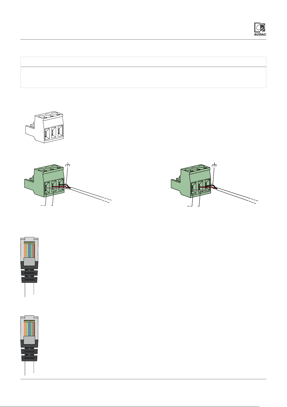
CONNECTION STANDARDS
The in- and output connections for AUDAC audio equipment are performed according to
international wiring standards for professional audio equipment
3-Pin Terminal block:
For balanced line input connections
Left:
Center:
Right:
For balanced signal input connections For unbalanced signal input connections
+
RJ45 (audio):
Remote input units
Pin 1 White-Orange Left channel +
Pin 2 Orange Left channel -
Pin 3 White-Green +24V DC
Pin 4 Blue Not connected
Pin 5 White-Blue Not connected
Pin 6 Green GND
Pin 7 White-Brown Right channel +
Pin 8 Brown Right channel -
Signal -
Signal +
Ground
(XLR Pin 3)
(XLR Pin 2)
(XLR Pin 1)
+
RJ45 (control):
Remote volume controller
Pin 1 White-Orange Not connected
Pin 2 Orange Not connected
Pin 3 White-Green GND
Pin 4 Blue Variable control voltage (0 ~ 10V)
Pin 5 White-Blue +10V
Pin 6 Green +10V
Pin 7 White-Brown Not connected
Pin 8 Brown Not connected
SCP2xx - User manual8
Page 9
Chapter 2
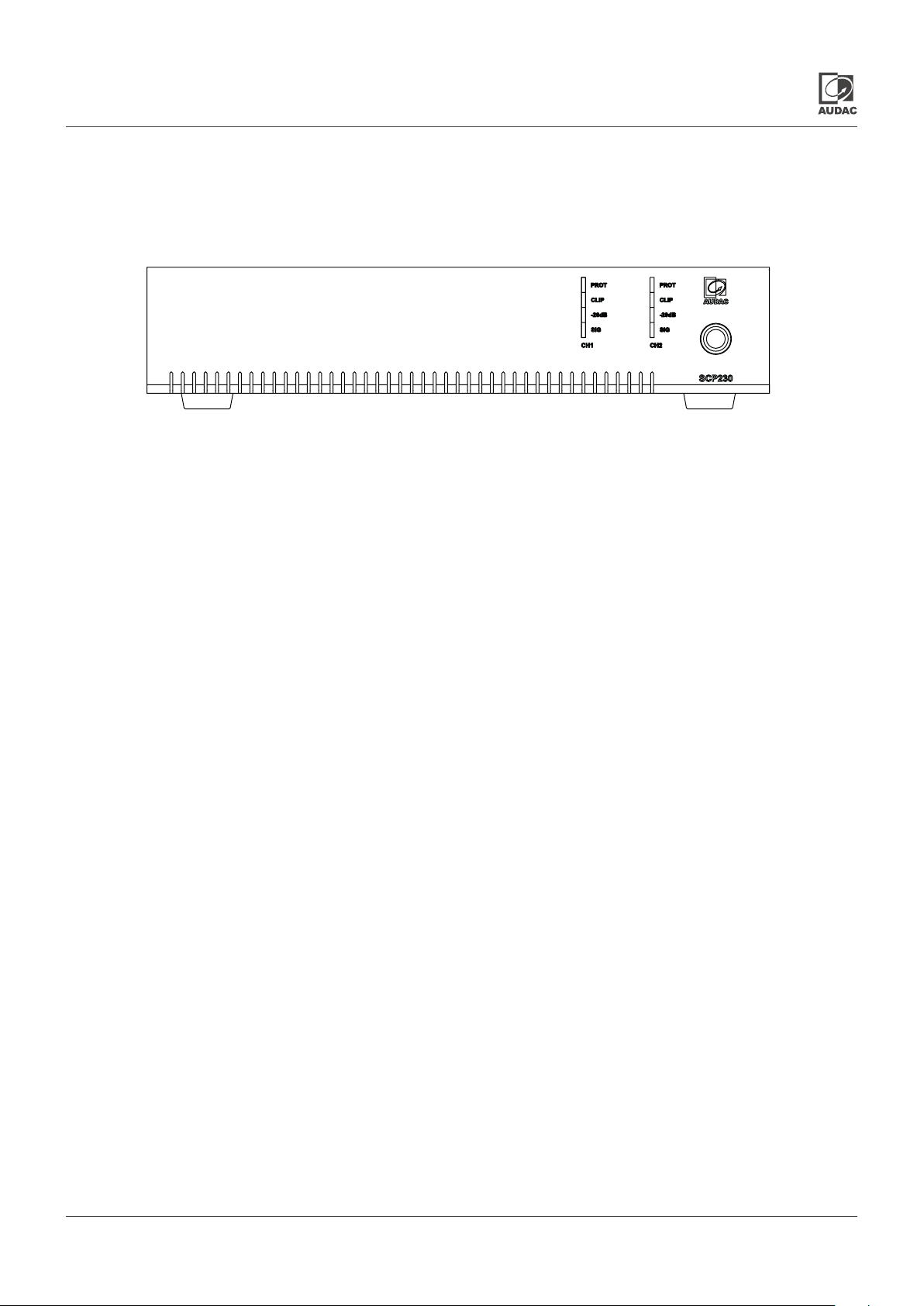
Front panel overview
Indicator LEDs (VU):
Channel monitoring is made convenient by four indicator LEDs for each channel.
The LEDs give a continuous indication of the operation of the corresponding channel. The green signal LED
illuminates whenever a signal is present, while the -20dB LED illuminates when the input signal exceeds the
-20 dB level. The Clip LED illuminates when the corresponding channel is working at the maximum level. To
ensure the best signal-to-noise ratio, the Clip LED should illuminate only (or maximum) at peak levels.
When the Clip LED illuminates, the output limiter of the amplifier will intervene avoiding a distorted “Clipping”
sound on the output. The Protection LED will illuminate when overheating occurs, or any other fault is detected.
When the protection LED is illuminated, no signal will be available on the outputs. The Protection LED will
also illuminate when the external mute contacts are activated.
Power switch:
A power switch is used to switch the amplifier on and off. The LED ring around the switch illuminates in blue
colour when the power is switched on or will illuminate in orange color when switched to standby mode.
SCP2xx - User manual 9
Page 10
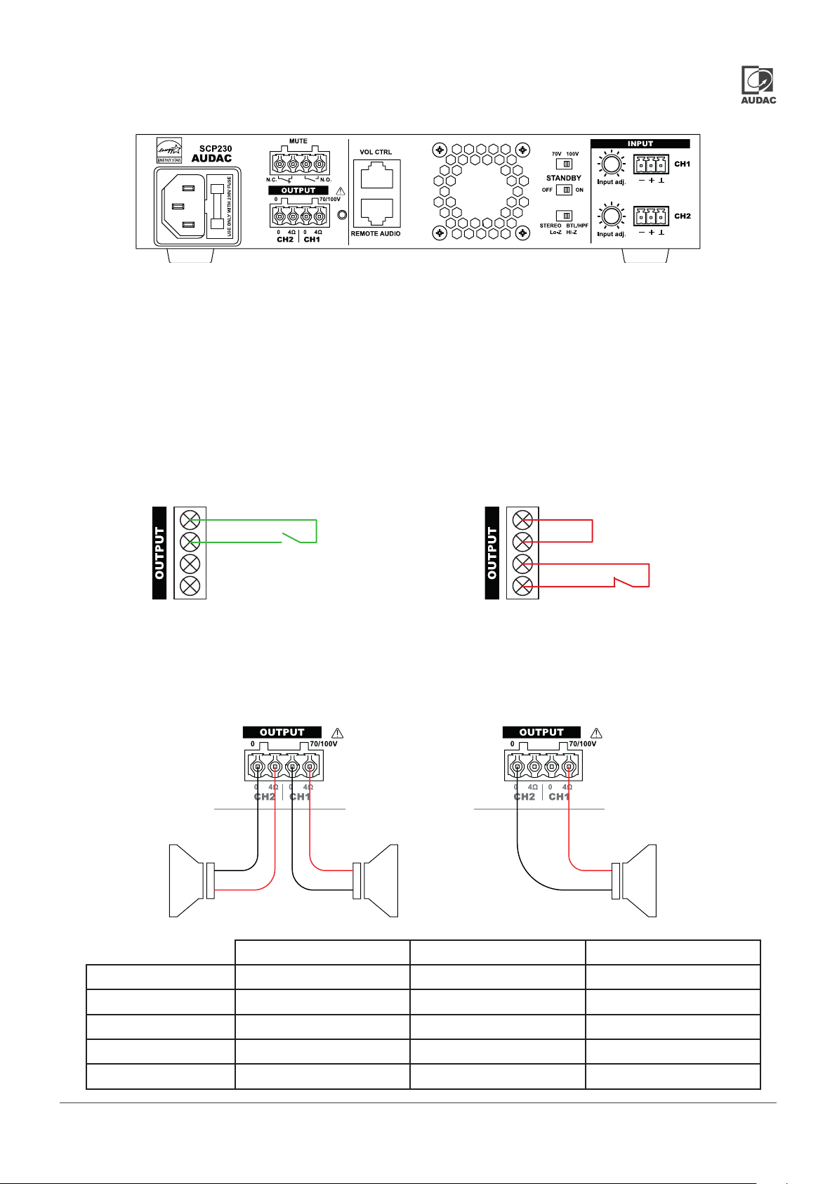
Rear panel overview
AC Power inlet with fuse:
The mains power supply (100-240V AC - 50/60 Hz) has to be applied to this AC power inlet.
Mute connection:
A priority mute contact connection is present which allows complete muting of background music in the
presence of a contact closure between both ‘MUTE’ contacts.
This contact is convenient for situations where a separate emergency system is installed and complete
background music muting is required. For example, on the occasion of a fire alarm. The emergency
system output contacts can be linked to this contact input. When a N.C. contact trigger is being used, a
contact bridge shall be used between both N.O. contact terminals.
Normal open mute contact diagram Normal closed mute contact diagram
N.O.
N.C.
Audio output connection:
The speakers shall be connected to the terminal block output connector. Depending on the setup, two
speakers can be connected in low impedance stereo setup, or one speaker line can be connected in a
constant voltage 70/100V bridge configuration. Typical wiring applications are shown in the following
diagrams.
SCP2xx connected in stereo mode
SCP series minimum load impedance in 4 Ohm stereo output mode
SCP2xx connected in bridge mode
N.O.
N.C.
Output voltage Impedance Power
SCP206 15.5 Volt 4 Ohm 2 x 60 Watt
SCP212 22 Volt 4 Ohm 2 x 120 Watt
SCP224 31 Volt 4 Ohm 2 x 240 Watt
SCP230 35 Volt 4 Ohm 2 x 300 Watt
SCP250 45 Volt 4 Ohm 2 x 500 Watt
SCP2xx - User manual10
Page 11
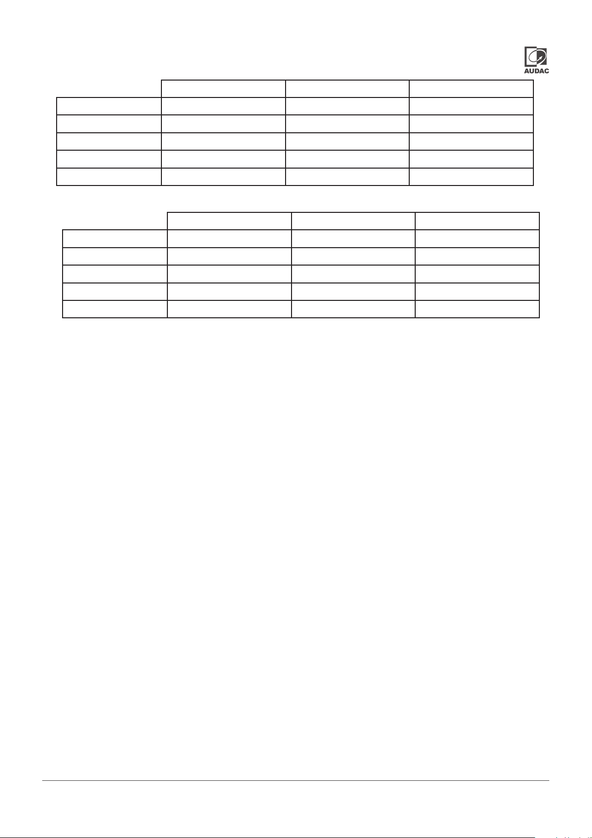
SCP series minimum load impedance in 70 Volt bridge mode
Output voltage Impedance Power
SCP206 70 Volt 41.67 Ohm 120 Watt
SCP212 70 Volt 20.83 Ohm 240 Watt
SCP224 70 Volt 10.41 Ohm 480 Watt
SCP230 70 Volt 8.33 Ohm 600 Watt
SCP250 70 Volt 5 Ohm 1000 Watt
SCP series minimum load impedance in 100 Volt bridge mode
Output voltage Impedance Power
SCP206 100 Volt 83.33 Ohm 120 Watt
SCP212 100 Volt 41.67 Ohm 240 Watt
SCP224 100 Volt 20.83 Ohm 480 Watt
SCP230 100 Volt 16.67 Ohm 600 Watt
SCP250 100 Volt 10 Ohm 1000 Watt
Remote audio input:
A remote audio wall panel (e.g. WP2xx) can be connected to the bottom ‘Remote audio’ RJ45 connector
for providing a remote audio input. The connection of this extension port can be made by using CAT5e (or
better) twisted pair cable in a straight pinout configuration.
Pinout and colour coding are described in Chapter 1 of this instruction manual. The remote audio input
provides stereo balanced line input with an input sensitivity of +12dBV and a +24V output for powering external
audio panels. The audio signal from the remote audio input is mixed with the amplifier’s line inputs.
Remote volume control:
The top ‘Vol Ctrl’ RJ45 connector allows for an external control of the main volume of the SCP amplifier. The
connection of this extension port can be made by using CAT5e (or better) twisted pair cable in a straight
pinout configuration. Pinout and colour coding are described in Chapter 1 of this instruction manual.
The remote volume controller connection is designed for use with a suitable volume controller (e.g. Audac
WP200, VC3208). It is a VCA input, working between 0-10V (linear envelope), and can be used with an external
0-10V control system. The amplifiers overall volume is controlled dependent on the applied control voltage.
A control voltage of 10V means no attenuation, while 0V mutes the amplifier. When no external controller is
connected, the volume is at maximum.
Standby switch:
The Standby mode of the SCP can be turned on or off. When enabled, the SCP will automatically go into
standby mode after 30 minutes of inactivity (no signal detection).
Stereo- (Lo-Z) / bridge- (Hi-Z) mode switch:
Provides the possibility to switch the amplifier between Lo-Z and Hi-Z modes. If this switch is set to Lo-Z
stereo, the output will be stereo can capable of driving low impedance speakers. If it is set to Hi-Z BTL/HPF,
both output channels are bridged and capable of driving high impedance / constant voltage speaker systems.
The output voltage can be switched between 70/100V through using a corresponding switch, depending
on the requirements of the installation. An HPF (70 Hz) will be enabled when switched to Hi-Z.
SCP2xx - User manual 11
Page 12

70V / 100V switch:
When switched in Hi-Z mode (STEREO - BTL-HPF) the output voltage can be switched between 70/100V
using this switch. In Hi-Z mode, the amplifier channel CH1 input is used and the input source should be
a mono-summed signal which is configured on the source side. When using a WP2XX as the source, the
wallpanel needs to be set to Mono mode using the DIP switch on the back.
Balanced stereo line input:
The balanced stereo line inputs use 3-pins terminal block connectors. All different kinds of balanced and
unbalanced line level audio sources can be connected to the line inputs. Some examples are pre-amplifiers,
mixers and spoken messages through an audio source. It is fitted with a gain control potentiometer by which
the input sensitivity can be controlled within a range of -3 dBV ~ +7 dBV.
SCP2xx - User manual12
Page 13
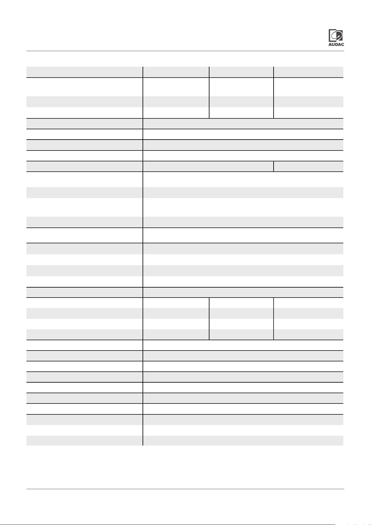
Technical specifications
SCP206 SCP212 SCP224
RMS/AES power
handling
Frequency response 20 Hz - 20 kHz
Signal / Noise > 95 dB
THD+N < 0.05%
Amplifier technology Class D
Cooling Convection cooled Fan cooled (controlled)
Inputs Balanced line
Outputs
Controls Gain control (potentiometer)
@ 4 Ohm stereo 2 x 60 Watt 2 x 120 Watt 2 x 240 Watt
@ 8 Ohm stereo 2 x 30 Watt 2 x 60 Watt 2 x 120 Watt
@ 70/100V bridge 120 Watt 240 Watt 480 Watt
2 x Balanced line input
3-pin terminal block ~ 3.81mm
Remote audio input RJ45
Remote volume
controller
Priority mute contact NO or NC
Low Z & 70/100V speaker output
4-pin terminal block ~ 5.08 mm
RJ45
Stereo low Z & mono high switch
70/100V switch
Standby ON/OFF
Power supply 100 ~ 240 V AC / 50 ~ 60 Hz
Power consumption Standby 0.5 W 0.5W 0.5W
Idle 19W 19W 19W
1/8 rated power 42W 60W 100W
1/3 rated power 75W 123W 220W
Ambient temperature range (in operation) 0°C ~ +40°C
Relative humidity range < 80 %, not condensing
Dimensions (W x H xD) 217.5 x 43.7 x 300 mm
Weight 2.70 Kg
Mounting 1/2 19” / 1 HE or tabletop
Construction Steel
Color
Optional accessories WP2xx remote wall panel inputs
WP200 Remote volume controller
MBS310 rackmount adapter
Black
SCP2xx - User manual 13
Page 14
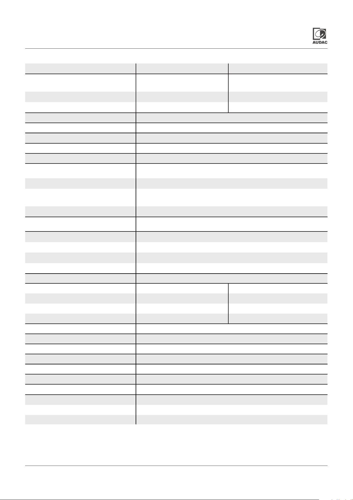
Technical specifications
SCP230 SCP250
RMS/AES power
handling
Frequency response 20 Hz - 20 kHz
Signal / Noise > 95 dB
THD+N < 0.05%
Amplifier technology Class D
Cooling Fan cooled (controlled)
Inputs Balanced line
Outputs
Controls Gain control (potentiometer)
@ 4 Ohm stereo 2 x 300 Watt 2 x 500 Watt
@ 8 Ohm stereo 2 x 150 Watt 2 x 250 Watt
@ 70/100V bridge 600 Watt 1000 Watt
2 x Balanced line input
3-pin terminal block ~ 3.81mm
Remote audio input RJ45
Remote volume
controller
Priority mute contact NO or NC
Low Z & 70/100V speaker output
4-pin terminal block ~ 5.08 mm
RJ45
Stereo low Z & mono high switch
70/100V switch
Standby ON/OFF
Power supply 100 ~ 240 V AC / 50 ~ 60 Hz
Power consumption Standby 0.5 W 0.5W
Idle 19W 19W
1/8 rated power 42W 200W
1/3 rated power 75W 400W
Ambient temperature range (in operation) 0°C ~ +40°C
Relative humidity range < 80 %, not condensing
Dimensions (W x H xD) 217.5 x 43.7 x 300 mm
Weight 2.70 Kg
Mounting 1/2 19” / 1 HE or tabletop
Construction Steel
Color
Optional accessories WP2xx remote wall panel inputs
WP200 Remote volume controller
MBS310 rackmount adapter
Black
SCP2xx - User manual14
Page 15

Notes
Page 16

Discover more on audac.eu
 Loading...