

Page 1

M2/R2DIS
Installation Manual
www.audac.eu
Page 2
2
Introduction
7” Touchscreen display kit M2/R2
The difference between M2DIS and R2DIS can only be found in the software inside
the unit. This installation manual covers the mounting instructions for both M2 and
R2 and uses pictures from the M2 for reference.
The M2/R2DIS is an optional display unit with touchscreen which can be installed
internally in the front panel of the M2/R2 digital audio matrix system. This unit
consists of a 7” TFT display panel with a resolution of 800 x 480 px that is fitted with
a resistive touch-screen panel. It is controlled by a powerful 32 bit processor which
communicates directly with the DSP processor.
This unit allows the user to operate the control functions of the matrix systems
without any external equipment. This can be useful when the system is installed in a
technical room where no external control devices are within reach.
Installation precautions
The installation of the display unit may only be performed by
qualified technicians.
Incorrect installation can lead to permanent damage or incorrect
functioning of the equipment.
Packaging contents
- M2/R2 Display module
- 2p powercable 500mm
- 20p Flatcable cable 80mm
- 9p Flatcable with D-Sub connector 600mm
- 4 pcs M3x10 mounting screw
- M2/R2DIS user manual
Page 3
3
Instructions
Mounting and connecting
Step 1:
Make sure the M2/R2 power inlet is disconnected from the mains
power.
Step 2:
Open the M2/R2 housing by carefully removing the screws from the top panel of the
device.
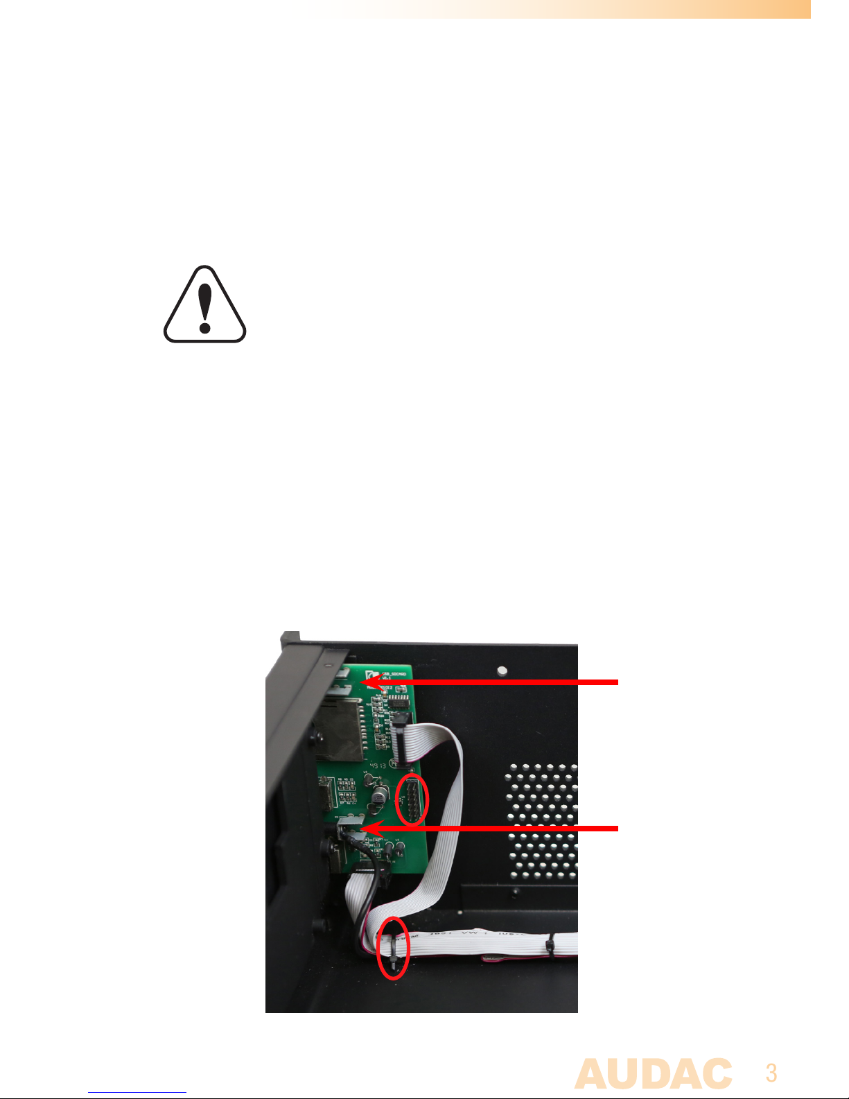
Step 3:
Remove the USB board on front of the device.
This is done by removing the two screws (marked by the red arrows) whereby the USB
board is fixed to the front panel. Take care not to damage the pinheaders while doing
this. By removing the nearest cable tie, you can give yourself enough space to install
the display module.
!
Page 4
4
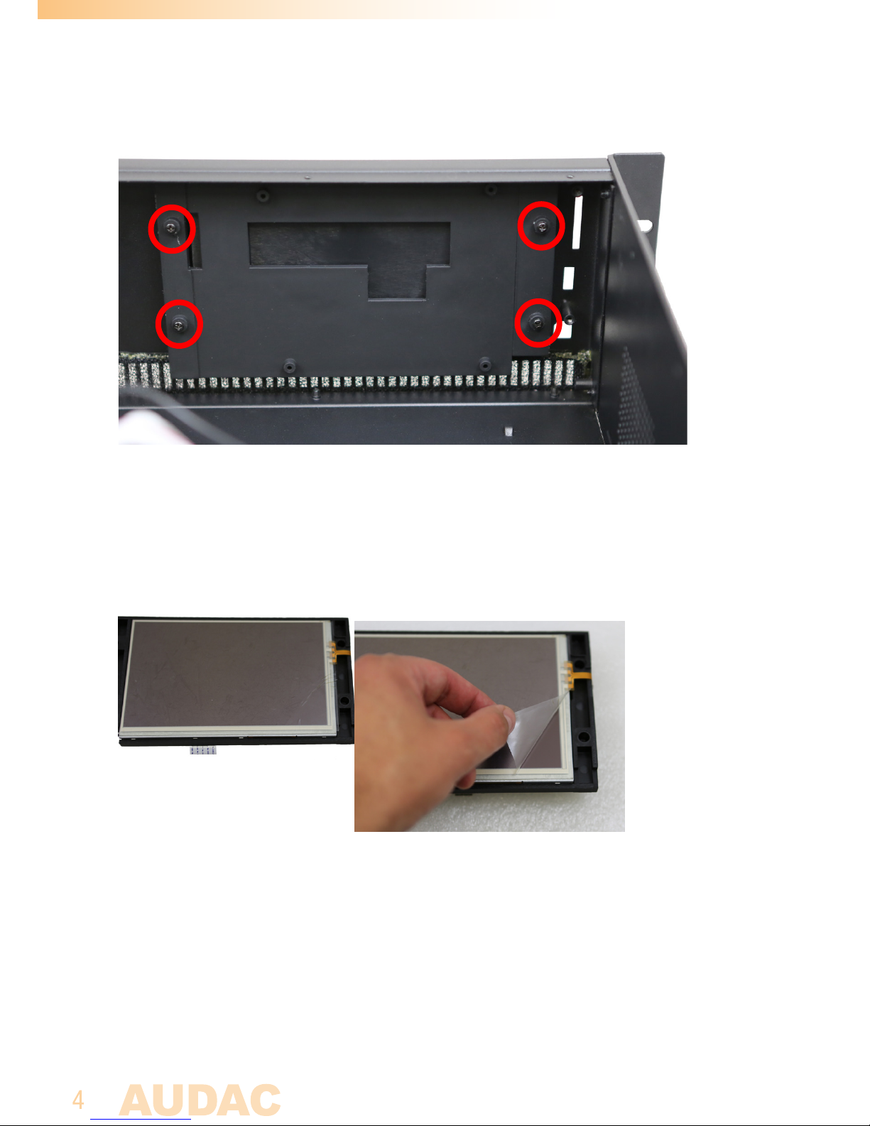
Step 4:
Remove the 4 screws holding the dummy-plate and take-out the dummy plate.
Step 5:
Remove the protective foil from the TFT screen.
Note: In case the unit is not used right away, keep the protective foil aside. The foil
should be refitted after installation to protect the screen again.
Page 5
5
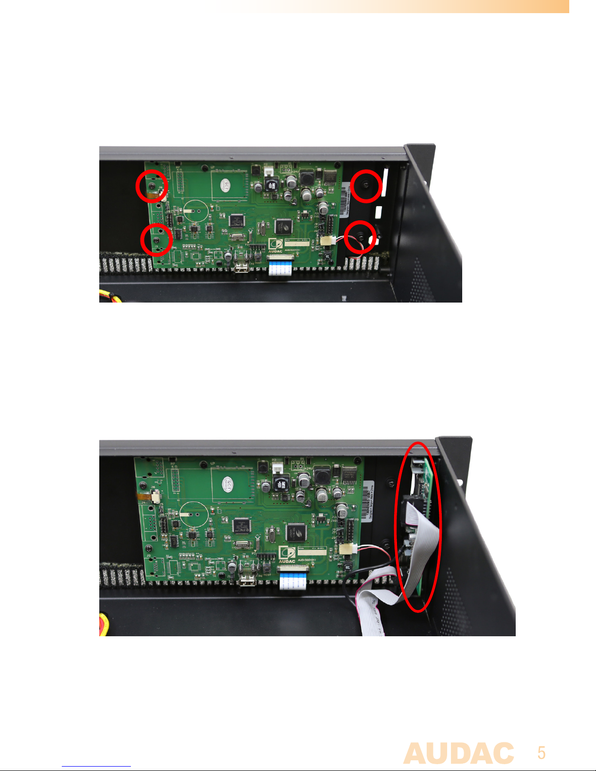
Step 6:
Assemble the display unit in the front panel of the M2/R2, at the location where
the dummy-plate was placed. Place and tighten the four screws again. Ensure the
screws are not over tightened, as this can prevent the unit from working!
Step 7:
Assemble the USB board back at the provided location on front of the device. Place
and tighten the two screws again, and make sure the USB unit is properly secured to
the front panel. Again, take care not to damage the pinheaders while tightening the
screws. (See step 3 of this manual)
Page 6
6
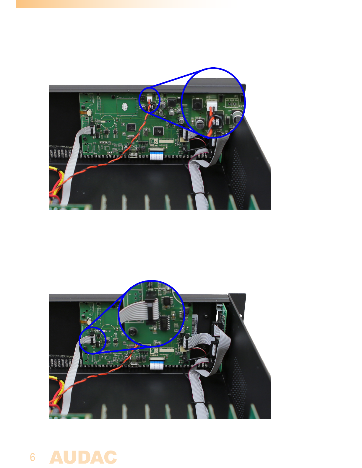
Step 8:
Connect the included power cable to the display unit. The power cable should be
connected to P3. Ensure the polarity when connecting the cable.
Step 9:
Connect the included communication cable (The one with the D-SUB connector) to
the display unit. The connection cable should be connected to P8.
Ensure it is positioned correctly.
Page 7
7
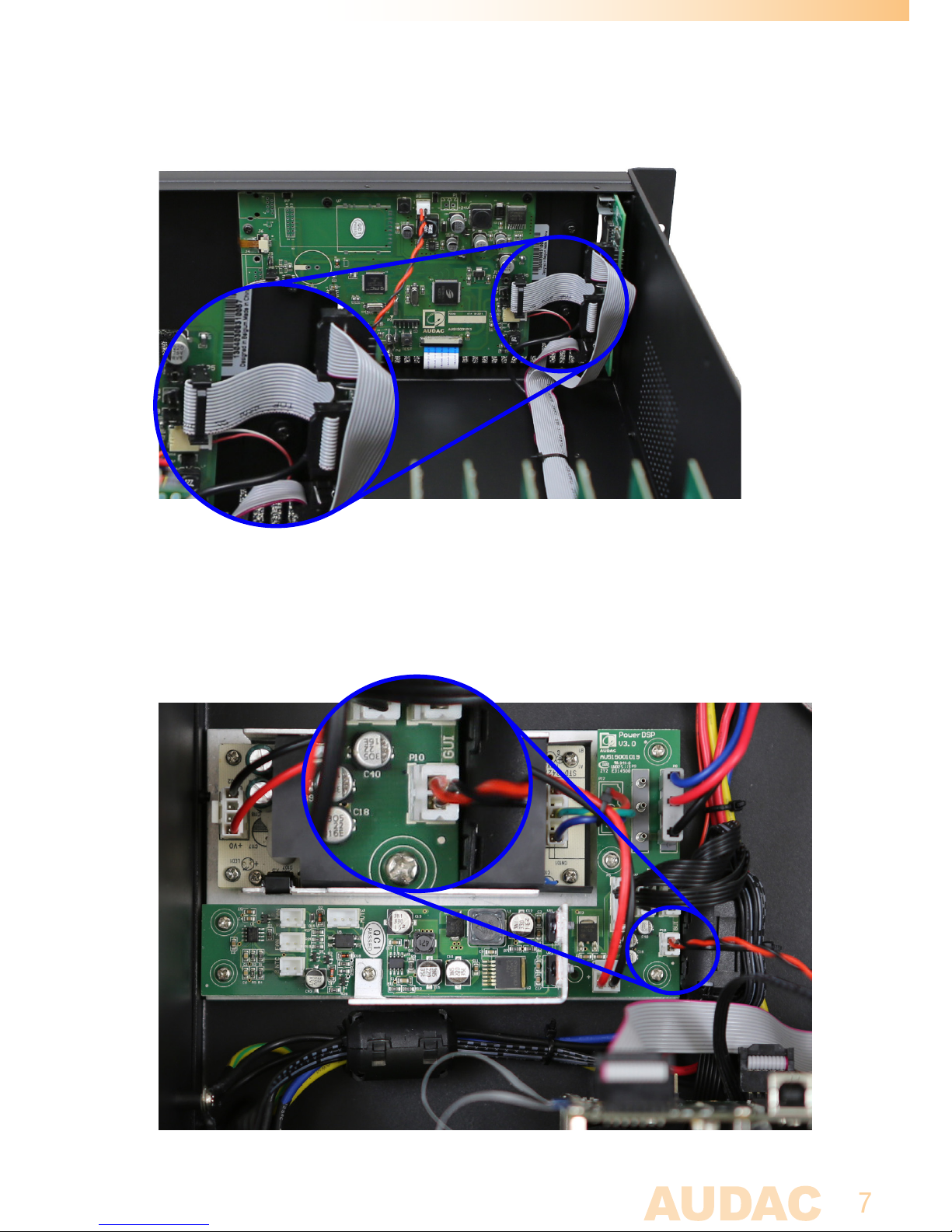
Step 10:
Connect the USB-bus (20p flatcable) of the M2/R2 to the USB-bus of the display as in
picture below.
STEP 11:
Connect the power cable coming from the display unit to the power supply. The cable
should be connected to the connector on the power supply marked with ‘GUI’.
Ensure the polarity when connecting the cable.
Page 8
8
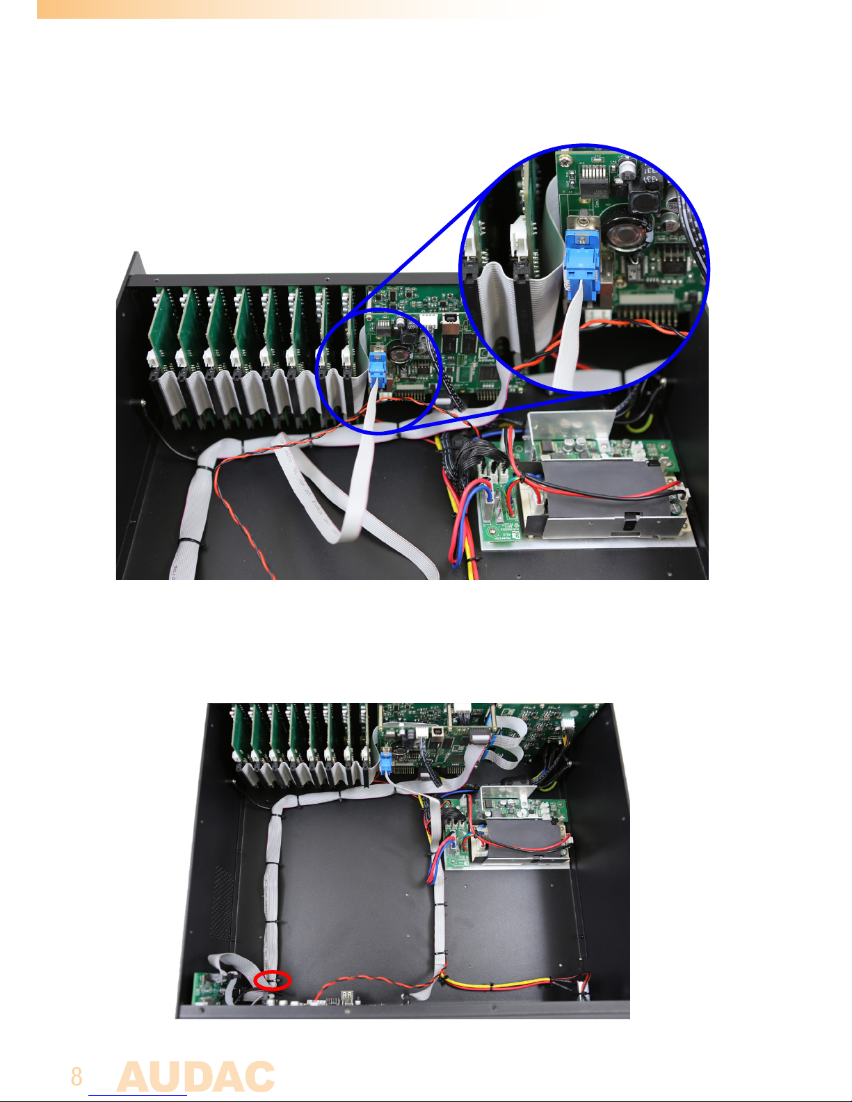
Step 12:
Connect the communication cable coming from the display unit to DSP board. The
cable should be connected to the D-Sub connector.
Step 13:
Place and fasten the power and communication cable together with the other cables
in a clean way using cable ties. Do not forget the one cable tie you removed in step 3!
!
Page 9
9
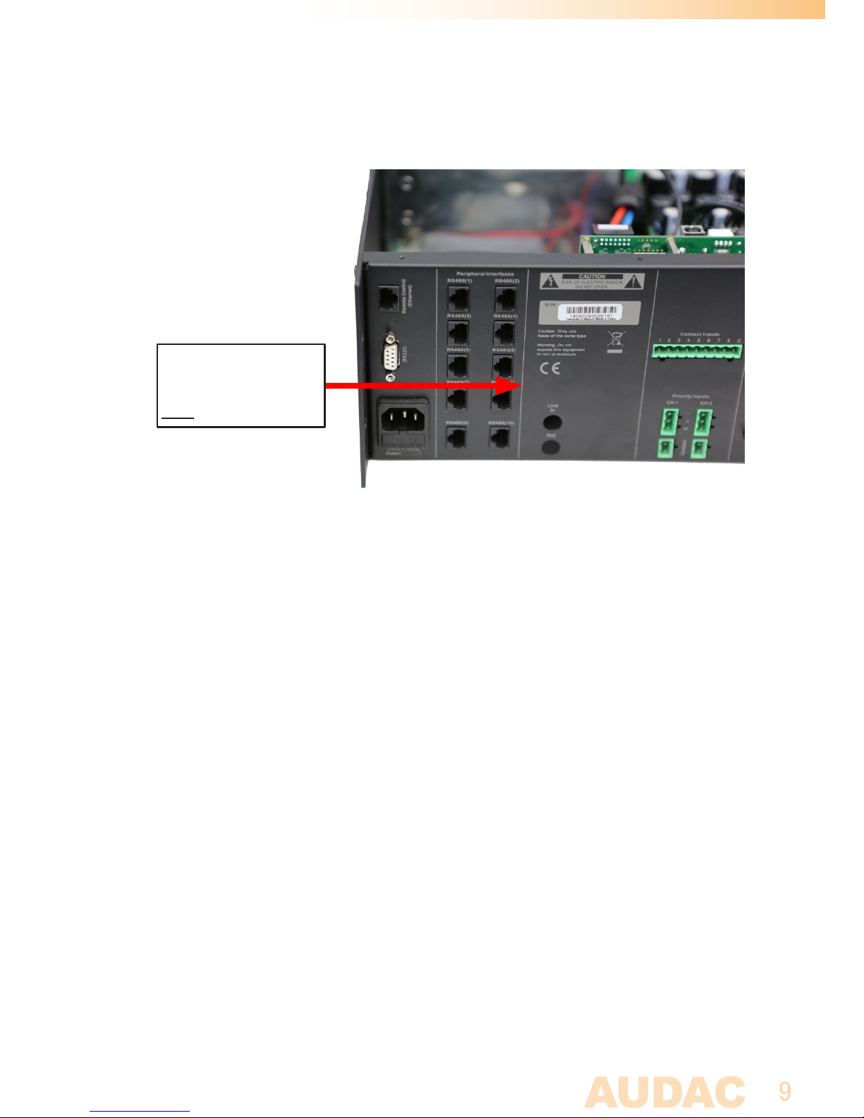
Step 14:
Finally, place the M2/R2DIS option label at the back of the unit at the designated
place.
Step 15:
The display unit is now properly installed. Close the housing, power up the system and
your matrix system including display unit is now ready for operation.
M2DIS option
1 4 0 8 0 3 0 8 3 1 0 0 0 1
S/N:14080308310001
 Loading...