

Page 1
R2
User Manual
www.audac.eu
Page 2

2
Page 3

3
Index
Introduction 5
Precautions 6
Safety requirements 6
Caution servicing 6
EC Declaration of Conformity 6
Waste of Electrical and Electronic Equipment 7
Caution symbols 7
Additional information 7
Chapter 1: Connections and connectors 9
Connection standards 9
Wire up the system 11
Chapter 2: Overview front and rear panel 12
Front description 12
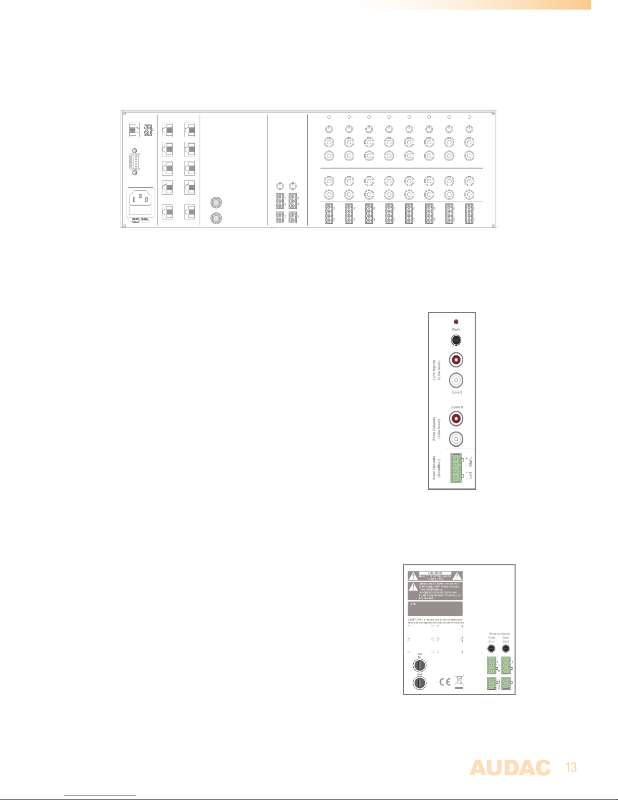
Rear description 13
Audio in- and outputs 13
Priority & Fiber link inputs 13
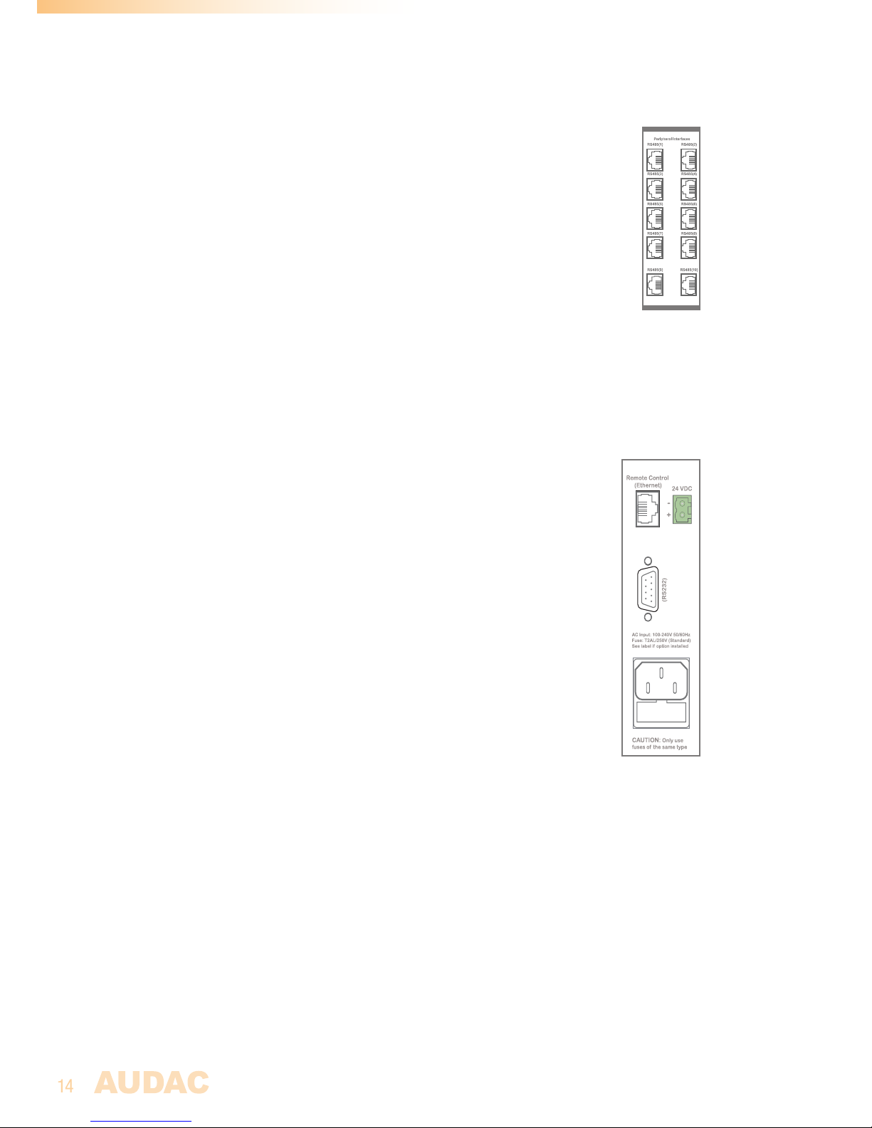
Peripheral interfaces 14
Control ports & Power inlet 14
Chapter 3: R2 Quick Start Guide 15
Connecting the R2 15
Configuring the R2 16
Chapter 4: User interface & configuration 18
Open the user interface 18
Login screen 18
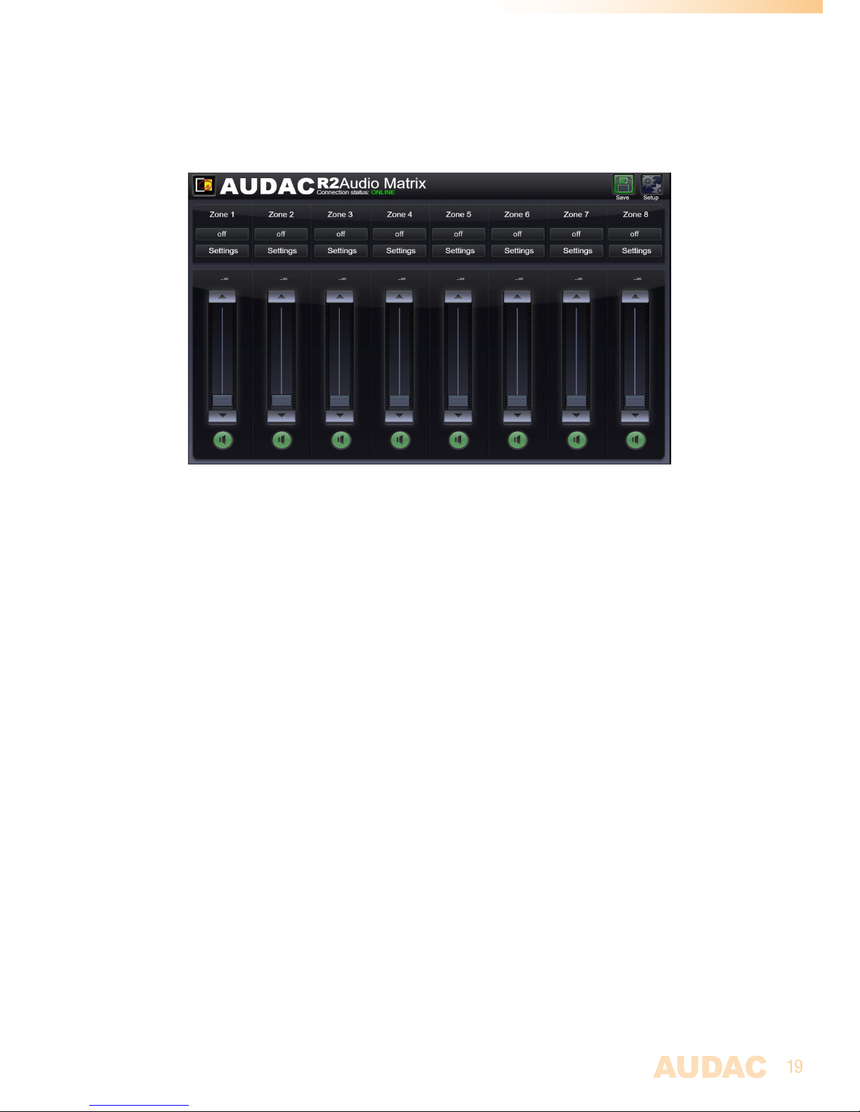
Main screen 19
Zone settings 20
Sound settings 22
Test signals 23
Zone linking 24
Input selection 25
Configuration settings screen 26
Timer settings 27
Time settings 28
Network settings 29
Paging settings 29
Priority settings 30
System configuration 31
R2 Address settings 32
Fiber settings 33
Amplifier bridging 34
Password settings 35
Factory settings 36
Page 4

4
Chapter 5: Peripheral interfaces 37
Wall mounted control panels 38
DW3020/4020 Basic wall panel 39
DW5066 All-in-one wall panel 40
Connection possibilities 42
Chapter 6: Paging 43
Chapter 7: Cascading the R2 48
Principle 48
Fiber audio flow 49
Setting up the project 51
Chapter 8: Additional information 55
IP Basics 55
Updating the R2 56
Technical specifications 57
Personal notes 58
Page 5

5
Introduction
Multi-Zone Audio Matrix System
The R2 is a Multi-Zone audio distribution system which is a truly polyvalent solution for
commercial and residential applications, with the flexibility of a multizone router. It delivers
a comprehensive and expandable powerful solution for nearly every situation. With its
large number of extension modules and configuration modes, it provides a solution for an
uncountable amount of installations – large or small, simple or complex.
It is standard equipped with 8 analog line inputs and 8 analog line outputs, but the flexible
structure of the device makes it easy to extend this number to an appropriate solution for
each specific situation.
If desired, it is easy to cascade multiple R2’s with the fiber interconnection modules. This
makes it possible to transfer up to 8 stereo channels and to extend to an nearly unlimited
number of zones.
But it is much more than that, due to the extremely powerful DSP processor, it provides
greater flexibility, higher reliability and lower latency than any other amplifier of its kind.
Moreover, it ’s capable of doing complex calculations on the digital audio signals, which makes
it possible to integrate digital filters into the system and generate complex audio signals.
Every R2 is standard equipped with an integrated Ethernet control interface which makes it
possible to configure and control the R2 from any PC, laptop or PDA which is connected to
the internet. Just use your browser, go to the appropriate website and you have complete
control of the R2.
An optional touchscreen can be installed in the front of the amplifier and there are optional
wall control panels whereby the desired music source and volume can be selected for a
specific zone.
A RS232 interface is provided for configuration and control with peripherals from other
manufacturers which make use of an RS232 connection, like AMX, Crestron,… the control
commands are freely available which makes it easy to develop specific applications that
work in combination with the R2.
Page 6
6
Precautions
READ FOLLOWING INSTRUCTIONS FOR YOUR OWN SAFETY
ALWAYS KEEP THESE INSTRUCTIONS. NEVER THROW THEM AWAY
ALWAYS HANDLE THIS UNIT WITH CARE
HEED ALL WARNINGS
FOLLOW ALL INSTRUCTIONS
NEVER EXPOSE THIS EQUIPMENT TO RAIN, MOISTURE, ANY DRIPPING OR SPLASHING
LIQUID. AND NEVER PLACE AN OBJECT FILLED WITH LIQUID ON TOP OF THIS DEVICE.
DO NOT INSTALL THIS UNIT NEAR ANY HEAT SOURCES SUCH AS RADIATORS OR
OTHER APPARATUS THAT PRODUCE HEAT
DO NOT PLACE THIS UNIT IN ENVIRONMENTS WHICH CONTAIN HIGH LEVELS OF DUST,
HEAT, MOISTURE OR VIBRATION
THIS UNIT IS DEVELOPED FOR INDOOR USE ONLY. DO NOT USE IT OUTDOORS
PLACE THE UNIT ON A STABLE BASE OR MOUNT IT IN A STABLE RACK
ONLY USE ATTACHMENTS & ACCESSORIES SPECIFIED BY THE MANUFACTURER
UNPLUG THIS APPARATUS DURING LIGHTNING STORMS OR WHEN UNUSED FOR LONG
PERIODS OF TIME
ONLY CONNECT THIS UNIT TO A MAINS SOCKET OUTLET WITH PROTECTIVE
EARTHING CONNECTION
EC DECLARATION OF CONFORMITY
This product conforms to all the essential requirements and further
relevant specifications described in following directives: 2004/108/EC
(EMC) and 2006/95/EC (LVD)
CAUTION - SERVICING
This product contains no user serviceable parts. Refer all servicing to
qualified service personnel. Do not perform any servicing (unless you
are qualified to)
Page 7
7
CAUTION
The symbols shown are internationally recognized symbols that warn about potentional
hazards of electrical products. The lightning flash with arrowpoint in an equilateral triangle
means that the unit contains dangerous voltages. The exclamation point in an equilateral
triangle indicates that it is necessary for the user to refer to the users manual.
These symbols warn that there are no user serviceable parts inside the unit. Do not open the
unit. Do not attempt to service the unit yourself. Refer all servicing to qualified personnel.
Opening the chassis for any reason will void the manufacturer’s warranty. Do not get the
unit wet. If liquid is spilled on the unit, shut it off immediately and take it to a dealer for
service. Disconnect the unit during storms to prevent damage.
WASTE ELECTRICAL AND ELECTRONIC EQUIPMENT (WEEE)
The WEEE marking indicates that this product should not be disposed
with regular household waste at the end of its working life. This
regulation is created to prevent any possible harm to the environment
or human health.
This product is developed and manufactured with high quality materials
and components which can be recycled and/or reused. Please dispose
of this product at your local collection point or recycling centre for
electrical and electronic waste. Do this to make sure that the product
is recycled in an environmental friendly way, and help to protect the
environment in which we all live.
ADDITIONAL INFORMATION
This manual is put together with much care and effort and is as complete as could be on
the publication date. However, updates on the specifications, functionality or software may
have occurred since publication. To obtain the latest version of both manual and software,
please visit the Audac website @ www.audac.eu.
Page 8
8
Page 9
9
Chapter 1
Connections and connectors
CONNECTION STANDARDS
The in- and output connections for AUDAC audio equipment are performed corresponding
to international wiring standards for professional audio equipment.
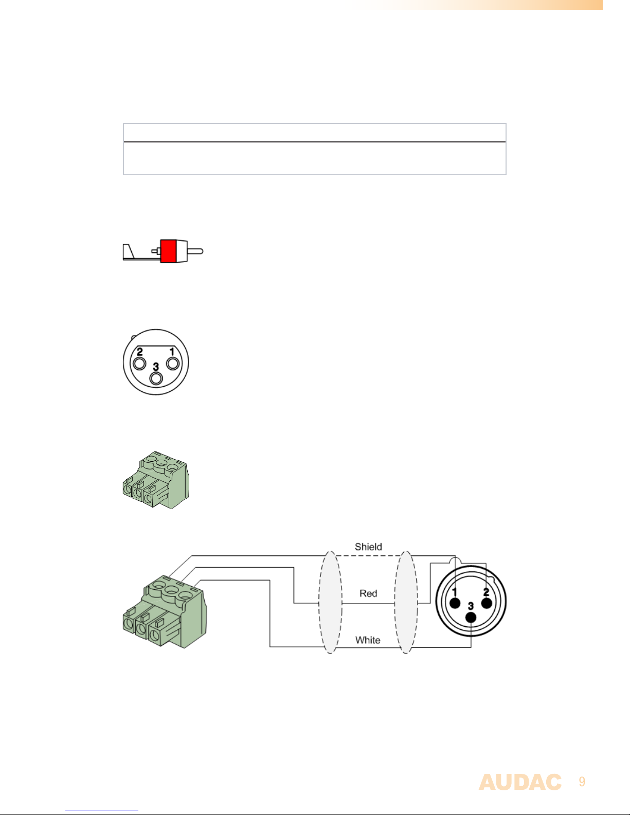
Cinch (RCA):
For unbalanced line input connections
Tip: Signal Sleeve: Ground
White: Left Red: Right
XLR:
For balanced microphone input connections. Image shows female port (receptacle)
Pin 1: Ground
Pin 2: Signal +
Pin 3: Signal -
3-Pin Euro-Terminal Block:
For balanced in and output connections
Left: Signal - (XLR Pin 3)
Center: Signal + (XLR Pin 2)
Right: Ground (XLR Pin 1)
For balanced line input connections:
For balanced line output connections:
Page 10
10
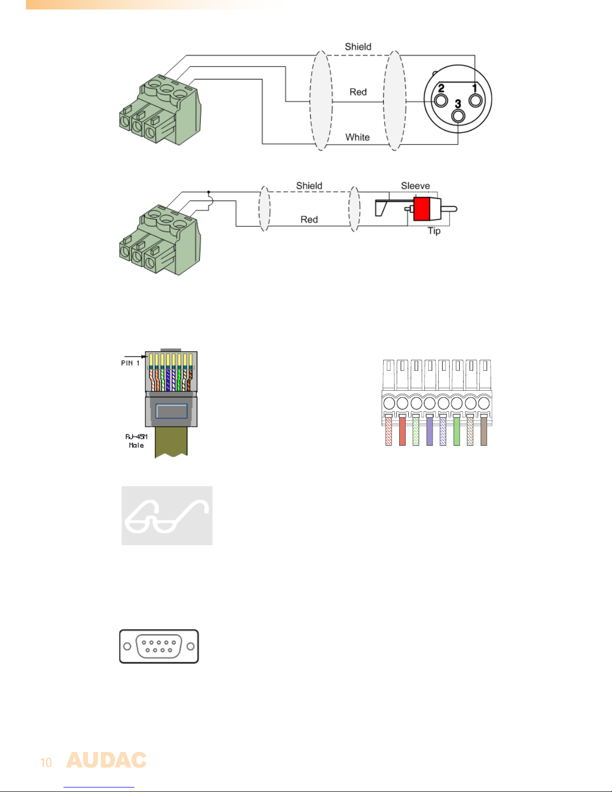
For unbalanced line in, output & priority connections:
RJ45 (RS485, Digital audio, +24V DC):
For connection to Wall Panels & Paging Consoles
Pin 1 White-Orange AUDIO TX A
Pin 2 Orange AUDIO TX B
Pin 3 White-Green +24V DC
Pin 4 Blue RS485 A
Pin 5 White-Blue RS485 B
Pin 6 Green GND
Pin 7 White-Brown AUDIO RX A
Pin 8 Brown AUDIO RX B
ATTENTION
The twisted pair cabling must always be ‘straight’. In case of
self-made cabling it must be wired as described above, to ensure
proper functioning of the system.
RS232 (serial connection interface):
For connection with home automation systems, or other remote control equipment
Connection Standard RS232
PIN 2 M2 TX
PIN 3 M2 RX
PIN 5 GND
Settings 19200 Baud
8 Bit
1 Stop bit
No parity
No Handshaking
1
Page 11
11
RS232 / RS485 / TCP/IP
The M2 has RS232, RS485 and TCP/IP ports which all accept the same commands. The
complete command set to control the M2 is available in the M2 commands user manual
which is freely downloadable on www.audac.eu
Wire up the system
The wiring of the system must be done according to the following rules, to guarantee
proper functioning of the system in all circumstances.
1. Speaker cable for amplified zone outputs:
Minimum 2 x 1.5 mm²
If distance > 15 m: 2 x 2.5 mm²)
2. Wall Mounted Input & Control units:
DW3020/4020 UTP/FTP Cat6 cable or better
DW5066 UTP/FTP Cat6 cable or better
APM1xx UTP/FTP Cat6 cable or better
2. Music sources and zone outputs:
Must be connected with high-quality audio cable and high-quality
connectors
3. Ethernet connection:
UTP/FTP Cat5e cable or better
Page 12
12
Chapter 2
Overview front & rear panel
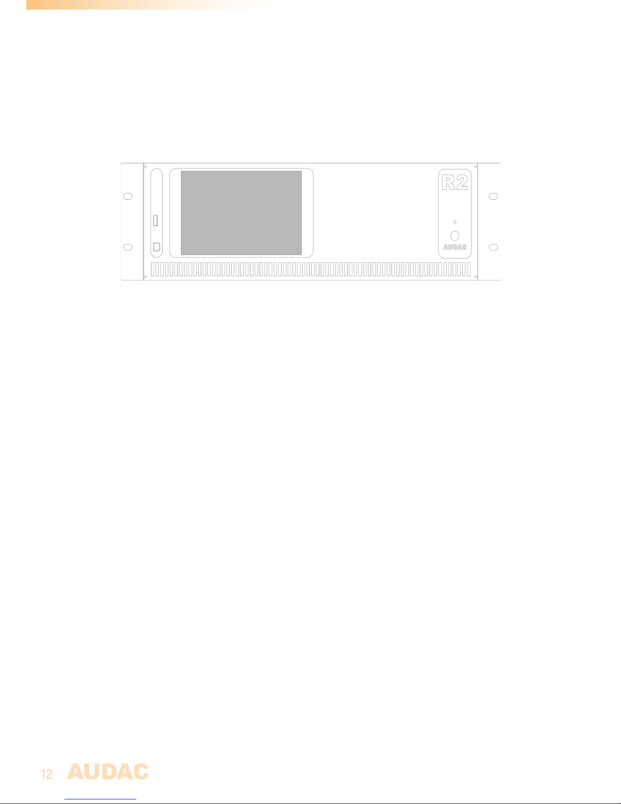
On the front of the R2 amplifier is a power button, One USB (A) connection for updating an
optional touchscreen (R2DIS) provided.
The power button is a latching type and should be used for powering-up the system.
When the power button is pressed, the R2 will startup. When the startup procedure is
taking place, the LED on front of the amplifier will blink blue. After the startup procedure
is completed, the LED will light-up blue, and the R2 will be ready for operation.
The largest rectangular area on the front of the amplifier is the location where the optional
touchscreen should be installed (R2DIS). This touchscreen can be used for controlling and
configuring all the functions of the R2 amplifier. This unit consists of a 7” touchscreen
with a format of 16/9 and a resolution of 800 x 480 px. A small integrated computer
controls the functions of the touchscreen.
The USB (B) connection port on front of the amplifier is dedicated for software updates.
When the touchscreen is installed.
Front
Page 13
13
8 line level in- and outputs are provided in its standard
configuration. Each line input is fitted with stereo RCA input
connectors and a clipping LED which illuminates when the
signal reaches the clipping level. By means of the gain control
potentiometers, the level of the input signals can be controlled.
Each zone output is fitted with RCA stereo connectors for the
connection of external amplifiers. When the optional power
amplifier kit is installed (POW), each output zone has an amplified
stereo with a power of 2 x 60 Watt @ 4 Ohm or 2 x 30 Watt @
8 Ohm. The amplified zone outputs can be bridged by Hardware,
Using the L+ and the R- to obtain a power of 120 Watt @ 8 Ohm
for each output zone.
Audio in- and outputs
Priority & Fiber
Two audio priority inputs and two priority contact inputs provided.
Depending of the configuration, 4 priority signals can be used. The
actions that need to happen when a priority signal occurs can be
freely programmed. There can be automatically switched to the
priority audio inputs when a audio signal is applied, or the internal
routing can be adapted when a signal is available on the contact
inputs.
The link in- and outputs are optical fiber connectors which can be
used for cascading multiple R2’s. For this feature, the optional fiber
interconnection module (OPT2) has to be installed.
Rear
Page 14
14
Peripheral interfaces
10 RJ45 (RED) connectors for expansion with additional wall panels and
in- and output modules are provided. All these connectors carry RS485 data
signals. This allows the control of the Matrix from 10 different locations.
8 of these connectors are able to carry digital audio signals (RS485(1) to
RS485(8)) for Audac paging microphones (APM) and all-in-one wall panel
DW5066.
Control ports:
The RJ45 remote control input should be connected to a LAN network.
This makes it possible to control the R2 system over Ethernet, by means
of a web-browser or mart devcie when combined with a WIFI router and
Audac touch.
The RS232 connection can be used to control the R2 with external
control equipment supporting RS232. This allows to couple the R2 with
your home automation system, and control it through hardware of other
manufacturers, like AMX, Crestron, ….
Power inlet:
The main power supply (110~240V AC / 50~60 Hz) has to be applied to
this AC power inlet. The connection is made by an IEC power connector
and is fitted with a fuse. When replacing the fuse, make sure that the
value of the replacement fuse matches the value of the original fuse.
(T2AL/250V)
Emergency power inlet (24 Volt):
A 24 Volts emergency power supply can be connected to this 2-pin
Terminal block connector for keeping the R2 running on emergency power
when the mains power is shut down. When the R2 is running on 24 Volt
emergency power, the function of the power switch on the front panel is
bypassed and can’t switch the R2 off.
NOTE: When installing the optional Power Amplifier kit, the fuse needs to be changed
accordingly, and should be replaced by a T4AL/250V fuse (included with POW2).
Control ports & Power inlet
Page 15
15
Chapter 3
R2 Quick start guide
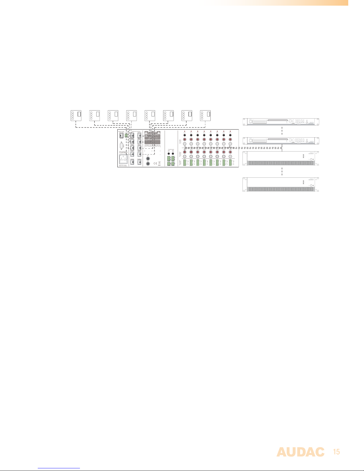
This chapter guides you through the setup process of a basic project with one R2 audio matrix
and 8 standard DW3020/4020 wall panels.
Overview of the R2 setup
Connecting the R2
1) Connecting audio sources
Connect all your audio sources (CD-players, tuners, ... ) to the line inputs (RCA
connectors) on the rear panel of the R2. Adjust all input gains to the appropriate level so
no clipping occurs.
2) Connecting amplifiers and/or speakers combined with a WIFI router and Audac
touch
Connect amplifiers (100V or low impedance) to the line outputs (RCA connectors) on
the rear panel of the R2. When the optional power amplifier kit (POW2) is installed, low
impedance loudspeakers can be connected to the loudspeaker outputs (Euro-Terminal
block connectors) on the rear side of the R2.
3) Connecting wall panels
Connect the DW3020/4020 wall panels to the Peripheral Interface (PI) inputs (RS485
connectors) on rear panel of the R2. Multiple DW3020/4020 wall panels can be connected
to one single PI input by using bus cabling (connecting all the wall panels in parallel), or
each wall panel can be connected to an PI input by a separate cable. It doesn’t matter
which PI port is used for which zone.
when connecting the DW5066 wall panels only one can be connected to any one RS485
port at any one time, these limits the total connectable DW5066 devices to 8.
It is recommended that the DW5066 is connected to the a port number that matches the
output it is controlling, this will make configuring the R2 and input naming easier during
the installation.
Prog.
Vol
+
-
+
-
Prog.
Vol
+
-
+
-
Prog.
Vol
+
-
+
-
Prog.
Vol
+
-
+
-
Prog.
Vol
+
-
+
-
Prog.
Vol
+
-
+
-
Prog.
Vol
+
-
+
-
Prog.
Vol
+
-
+
-
Audio sources
Amplifiers
Wall panels
Page 16

16
4) Connecting a computer
A computer can be connected to the R2 through true ethernet. If the computer is directly
connected to the R2, a crossed network cable is necessary. If the R2 is connected to
a local LAN network (connected to a router / switch / hub) a straight network cable is
necessary. Ask your IT administrator for help.
To get access to the user interface, enter the following address in your internet browser
address bar: “http://192.168.0.191” (This is the factory default IP address of the R2, can
be changed in the user interface). The default administrator password (gives you access
to all functions) is “R2” and the default user password (gives you only access to the basic
functions) is “user”. If you want to make any changes to the settings, you should log-in
with the administrator password.
Configuring the R2
1) Changing the IP address
You can skip this step when the default IP address “192.168.0.191” is not used by another
device in your network, and is OK for you. If you like to change the IP address, go to
the “Setup” menu (click the icon in the upper right corner of the main screen) and click
“Network Settings”. Now you can change the IP address, and click “OK” to apply the
changes and save. Afterwards, your browser will be automatically redirected to the new IP
address of the R2, and the default IP address is not longer valid.
2) Changing the password
You can skip this step if the default password “R2” for administrator and “user” for users
is OK for you, buy we always recommend to change these passwords, especially when
your R2 is connected to a public network where external users have access to. If you like
to change the password, go to the “Setup” menu and click “Password settings”. Here you
can change the passwords. First, the old password needs to be entered, and subsequently
the new password needs to be entered twice (Max 10 characters). Press the “OK” button
to save the new password. Now, you always need to log-in with the new passwords and
the default passwords are not longer valid.
3) Configuring wall panels and sources
Go to the “Setup” menu and click “System configuration”. Now you have the possibility
to choose between “Paging”, “DW5066” and “DW3020/4020”. To configure the settings
for the DW3020/4020 wall panels, click the corresponding button. By the dropdown list
on the left side, you can choose for which zone you want to configure a wall panel. After
the desired zone is selected, you can assign one of the connected wall panels with that
particular zone by clicking “Set Address”. The displays on all wall panels will start blinking
with the selected zone number. Push the “Program +” button on the wall panel if you
want to assign that particular wall panel with the selected zone. After the “Program +”
button is pressed, the wall panel will be linked with the selected zone, and the display will
stop blinking.
The R2 contains many different inputs which can be selected to link with a zone. 8
of those inputs are accessible through the “Quick menu” (dropdown list on the main
page). The same inputs which are available in the “Quick menu” can be selected on the
DW3020/4020 wall panels. The other inputs are accessible through the settings menu if
you are logged-in as administrator.
You can choose the inputs which are selectable in the “Quick menu” and with the
DW3020/4020 wall panels through the “Input selection” menu in the “Zone Settings”
Page 17

17
window (Standard are line inputs 1 to 8 selected). Simply select the desired input signals
by the dropdown lists on the corresponding location. After the desired input channels are
selected, click the “Set inputs” button to save the changes. The selected inputs are now
selectable in the “Quick menu” and by means of the wall panel.
Ready
Your system is now ready for use with the wall panels.
Page 18

18
Chapter 4
User interface & configuration
To get access to the control and configuration settings, the R2 should be connected to a
computer or an Ethernet LAN network. For more information about network connections
and settings, see IP basics in chapter 8.
The standard (factory default) IP address of the R2 is 192.168.0.191, make sure this
address is within the IP range of the connected Ethernet LAN network (subnetmask
255.255.255.0). If the default network address is not within range of your LAN network,
contact your network specialist. The network address can be changed with the Standard
Web Based User Interface but therefore a network connection has to be made first!
Any device (PC, Laptop, PDA or even a Smartphone) with a web browser and the
Macromedia Flash 8.0 plug-in (or higher) installed, can be used to control the web based
user interface.
For smart devices, a special application has been developed to control the standard
functions of the R2 Matrix. this application is called the Audac touch.
Open the user interface
Connect the R2 to your network using a straight cable, it is recommended that the port
connected to the Audac R2 is set to a speed of 10/100MB. Ensure that the computer being
used to control the R2 is within the same range and the default IP address for the R2
192.168.0.
Start your default web browser and enter in the address bar the IP address of the embedded
web server of the R2. (The factory default IP address is http://192.168.0.191).
If multiple R2’s are cascaded with each other through the fiber interconnection interface,
first a selection screen will be displayed whereby the R2 should be selected which you want
to control.
Login screen
First the login screen will be displayed.
A password should be entered to get access to the web interface of the R2 amplifier.
There are two different access levels, administrator level and user level.
If you log-in using the administrator password, you get access to all functions and
configuration options of the R2 Amplifier (The factory default password for administrator
access is “R2”).
When you log-in using the user password, you only get access to the basic functions of
the R2 Amplifier, such as changing the volume and changing the routing for a particular
output zone. (The factory default password for user access is “user”).
After the right password is entered, click the “OK” button, and you will be redirected to
the main screen of the R2 interface.
NOTE
The passwords can be changed in the Configuration >> Password settings menu (Only administrator)
Page 19
19
Main screen
The main screen displays all 8 output zones of the R2 with fader volume controls.
Volume control
The volume of each channel can be set by moving the fader of the corresponding channel
up or down. At the top and bottom side of each fader is a button with an arrow displayed
whereby the volume can be raised or lowered in steps of 1 dB. At the bottom is a “Mute”
button provided which mutes the volume of the corresponding output channel in one click.
After the volume is muted, this mute button will become Red, and the volume can be
unmuted after clicking it again.
Assign zone names
For a better overview of all output channels, every fader can be assigned by a specific
zone name as shown in the example below. The name of the zone can be changed by
double clicking on the name which is displayed above the corresponding fader (indicated
in the picture below with “Zone (number)”). When a cursor comes up, remove the existing
name with the backspace key, and just change the name in the desired name. Click on
the “Save”(green button top right corner) button and confirm to save the changed zone
settings. The name of the corresponding zone will be changed, and next time you log in to
the web based user interface of the R2 the same zone name will be displayed.
Connection status
In the top left corner of the window is the “Connection Status” displayed. To have
communication with the R2, the connection status must be “ONLINE”.
Input channel selection
The desired input signal for a particular zone can be selected by using the dropdown
menu below the zone name. This dropdown menu shows 8 audio input signals which
become the quick default inputs for that zone. When no input signal is selected, the option
“Off” will appear. When a input is selected which is not one of the 8 in the dropdown
menu “other will be displayed.
Editing the selectable inputs within this menu should be done by means of the “input
Page 20
20
Zone settings
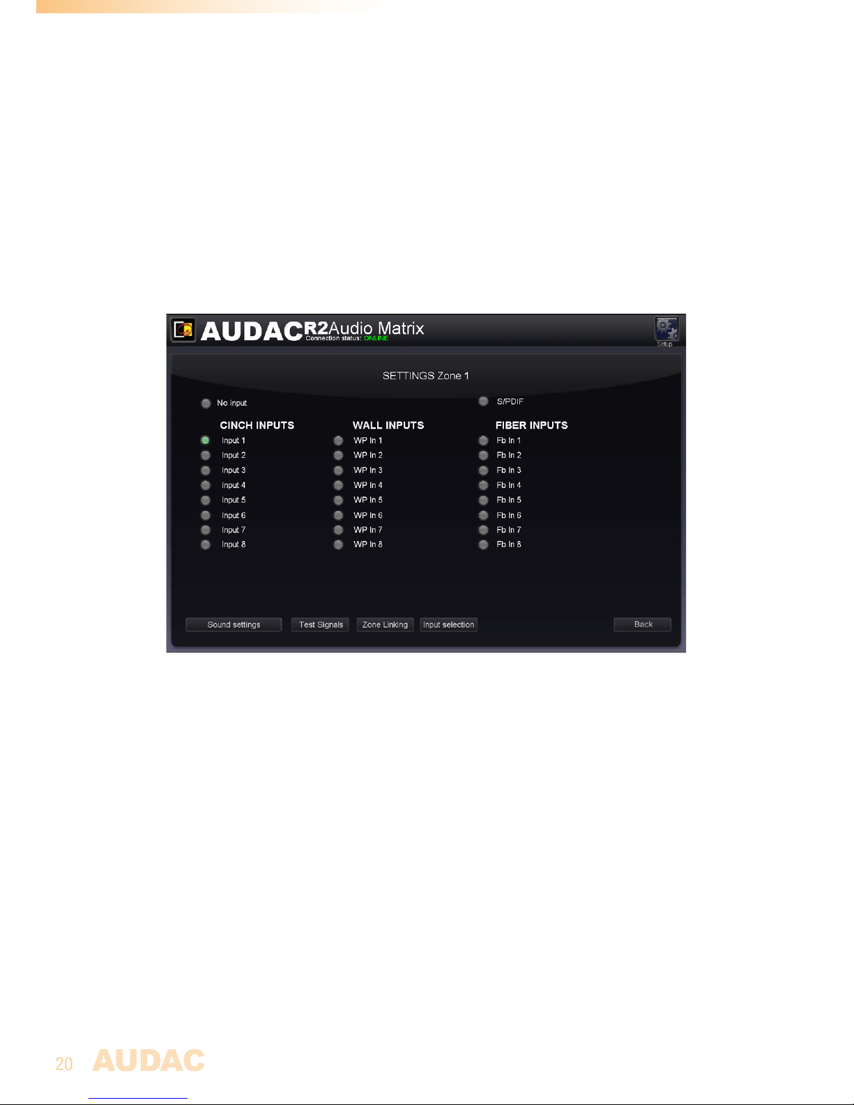
After clicking on a “Settings” button, displayed by a fader of a specific zone, you will
be redirected to the “Zone Settings” window. This window gives an overview of all the
settings that can be applied to one specific zone.
Zone settings
Input channel selection
The first window gives an overview of all input channels which can be patched to that
particular output zone. The first displayed option is ‘No Input”, which means when this
option is selected, no input signal will be routed to that particular output zone. At the same
level is the S/PDIF selection button displayed.
Below are from left to right the “Cinch inputs”, the “Wall inputs” and the “Fiber inputs”
displayed.
The “Cinch Inputs” are the direct line inputs which are provided on the rear panel of the
R2 by means of RCA connectors. In the second table are the “Wall Inputs” displayed.
These are all additional input signals (Line or Microphone) which are connected to an
optional wall input unit (DW5066) inputs on the rear side of the R2. In the third table are
the “Fiber Inputs” displayed (Only functional when the optional OPT2 module is installed).
These are the digital audio channels which are transferred over the fiber interconnection
interface, and can be patched to the selected output zone.
To select the desired audio input source which has to be patched with the selected output
channel, simply click the button next to the desired input source. The selected input signal
selection screen” menu, which can be obtained by clicking the “Settings” button below
the “Input Selection” dropdown list. In this case, the option “Other” will appear.
Configuration menu
In the top right corner is a “Setup” button displayed. After clicking this button, you will be
redirected to the general configuration menu of the R2.
Page 21

21
will be indicated in Green.
At the bottom of this window, four additional selection buttons “Sound Settings”, “Test
Signals”, “Zone Linking” and “Input selection” are displayed. In the “Sound Settings”
menu, specific configuration settings such as applying a digital filter or tone control can
be made. In the “Test Signals” menu can be selected which kind of test signal should be
patched to the particular output zone. In the “Zone linking” menu can be set which zones
should be linked with each other and in the “Input selection” menu can be selected which
input signals should be shown in the input preset menu.
Back
Click the “Back” button to go back to the main window.
Save zone settings
To make sure the changed zone settings are still effective after shutdown and restart of
the R2, the “Save” button on the main screen of the R2 need to be pressed. At the same
time, the volume and routing settings will be saved.
Page 22
22
Zone settings >> Sound settings
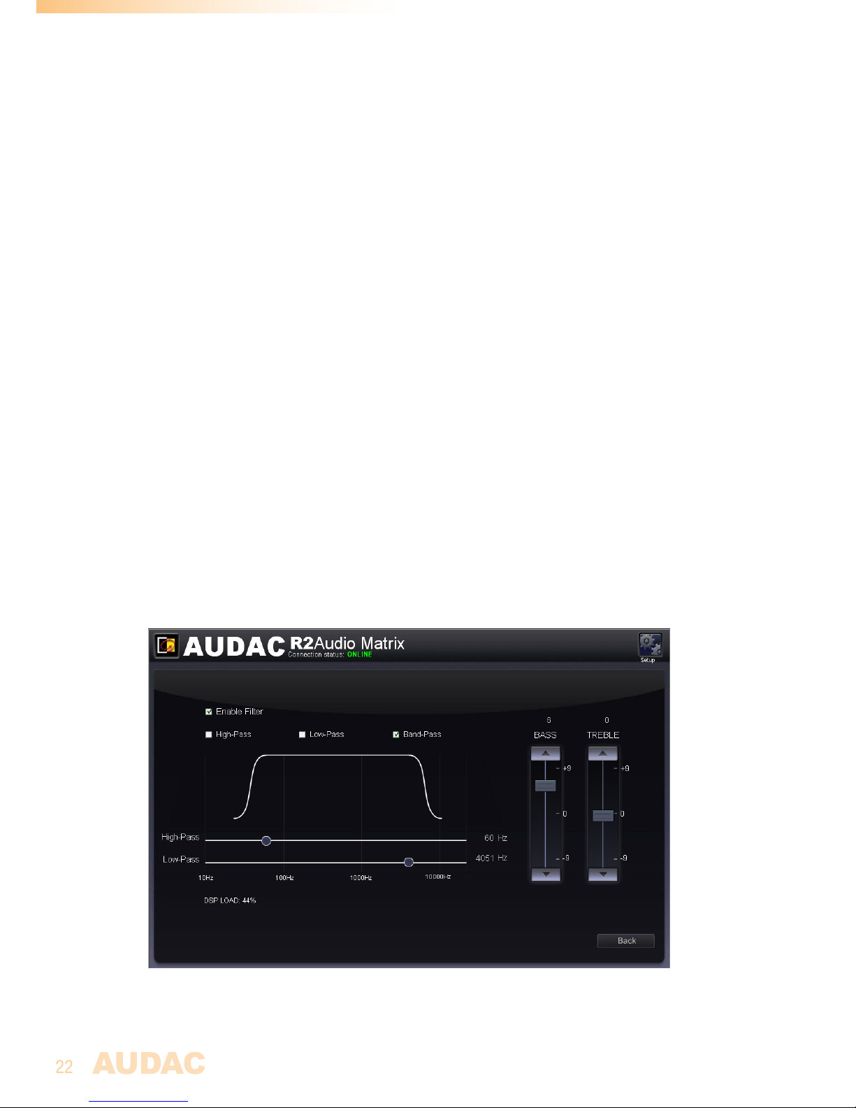
The “Sound Settings” window offers the possibility to apply a digital filter to the selected
output zone, and to adjust the sound settings by means of the two-band tone control.
Digital Filter
To apply a filter to the selected output zone, tick the “Enable Filter” checkbox and select
the desired filter type between High-Pass, Low-Pass and Band-Pass. With a High-Pass
filter, the frequencies below the crossover frequency will be suppressed, with a LowPass filter, the frequencies above the crossover frequency will be suppressed, and with
a Band-Pass filter, the frequencies higher than the upper crossover point, and below the
lower crossover point will be suppressed.
After the desired filter type is selected, the slide-bars to adjust the crossover frequencies
will be displayed. The crossover frequency can be adjusted by sliding the button on the slider
scale to the left and the right. The frequency can be set between 10Hz and 22kHz, and the
exact set crossover frequency is displayed on the right side of the slider scale.
Two band tone control
Along the filter settings, two faders displayed on the right side which are meant to adjust
the sound settings through two-band tone control. The left most fader indicated with
“Bass” offers the possibility to adjust the level of the low frequencies, while the right
most fader indicated with “Treble” offers the possibility to adjust the level of the high
frequencies. The sound level for both low and high tones can amplified or attenuated
between +9 dB and -9 dB. This can be easily done by sliding the faders up and down in
the same way as the volume control on the main screen.
Back
Click the “Back” button to go back to the previous window.
Sound settings
Page 23
23
Zone settings >> Test signals
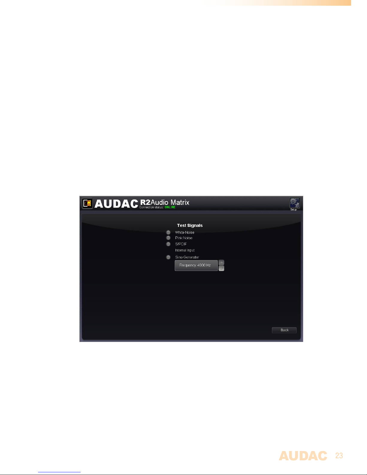
The test signals window gives an overview of all special input signals which can be
patched to the selected output zone. The R2 has an internal digital signal generator which
can generate white noise, pink noise and sinusoidal signals with a selectable frequency.
Each of those signals can be patched to any output zone.
Signal Selection
For patching those signals to the selected output zone, simply click the button which is
displayed next to the desired signal, and the selection button will become green when the
signal is selected.
When the “Sine Generator” is selected, the output frequency of the generator can be adjusted
by clicking the up and down arrows displayed next to the selected frequency.
When one of the test signals is selected, “Other” will appear in the ‘Input Selection” box on
the main screen.
Back
Click the “Back” button to go back to the previous window.
Test signals
Page 24
24
Zone settings >> Zone linking
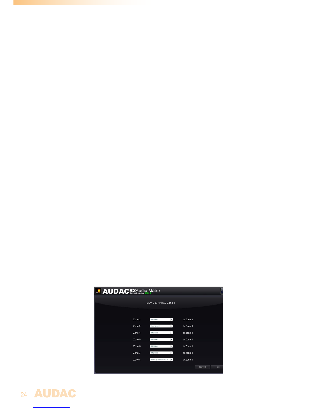
The “Zone Linking” window offers the possibility to link several zones with each other,
making the zone settings like volume and routing coupled with each other. There is the
possibility to make a permanent linking or a linking under certain conditions (priority
contact) between the different zones.
Linking
All zones which can be linked to the selected output zone are shown in a list underneath
each other. Next to each zone name, a dropdown list is shown whereby the linking can
be selected. The standard setting is set to “Not linked”, and the linking method can be
selected between “Linked by Prio contact 1”, “Linked by Prio contact 2”, and “Fixed
Linked”.
When several zones are linked with each other and any change is made to the volume or
routing settings from one of the linked zones, the other linked zones will automatically
follow the same changes made to the settings.
Linked by priority contact
When the “Linked by Prio contact 1” or “Linked by prio contact 2” options are selected,
the zones will be linked with each other when a connection is made between the priority
contacts which are provided on the rear side of the R2. The linking between the zones will
remain as long as the contact is established. For example, this can be done by means of a
switch or relay.
Fixed Linked
When the ‘Fixed Linked” option is selected, the linking between the zones will be
permanently present.
Slave
When a zone already is linked with another zone, the linked zone will be called the “Slave”
from the “Master” zone and the linking settings for this zone will be unavailable. When
selecting the “Zone Linking” for this zone, the message “Zone is already slave of another
zone” will appear.
Back
Click the “Back” button to go back to the previous window.
Zone linking
Page 25
25
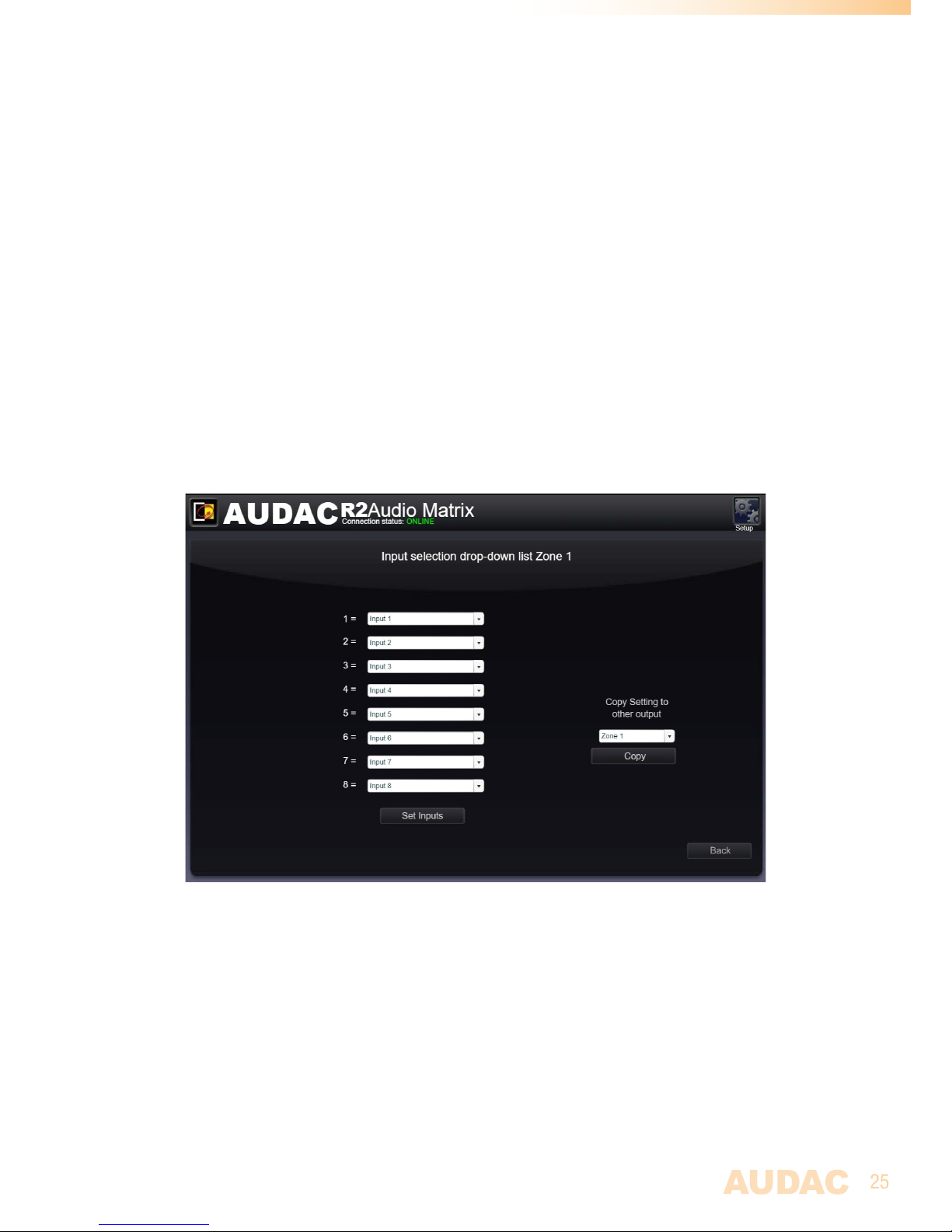
Zone settings >> Input selection
The “Input Selection” window allows you to make a selection out of all available input signals for the
“Quick Selection Menu”. This is displayed on the main screen just below the zone name. It is convenient to
add the 8 common used and most important input signals to the “Quick Selection Menu”.
Moreover, the input signals selected in this menu are also the 8 signals which are selectable by the
DW3020/4020 wall panels linked with this zone.
Selection
This window gives an overview of 8 listboxes, each corresponding with a number from 1 to 8. When
clicking this listbox, all input signal possibilities will be shown, ranging from the direct line inputs to the
fiber and wall panel inputs as well as the internal test signals. After the 8 inputs are selected, click the ‘Set
inputs’ button and the selected inputs will be assigned with this zone.
Copy
Copy settings to other zones. by using this option, you can quickly copy input slection to other zones.
Back
Click the “Back” button to go back to the previous window.
Input selection
Page 26
26
Configuration settings screen
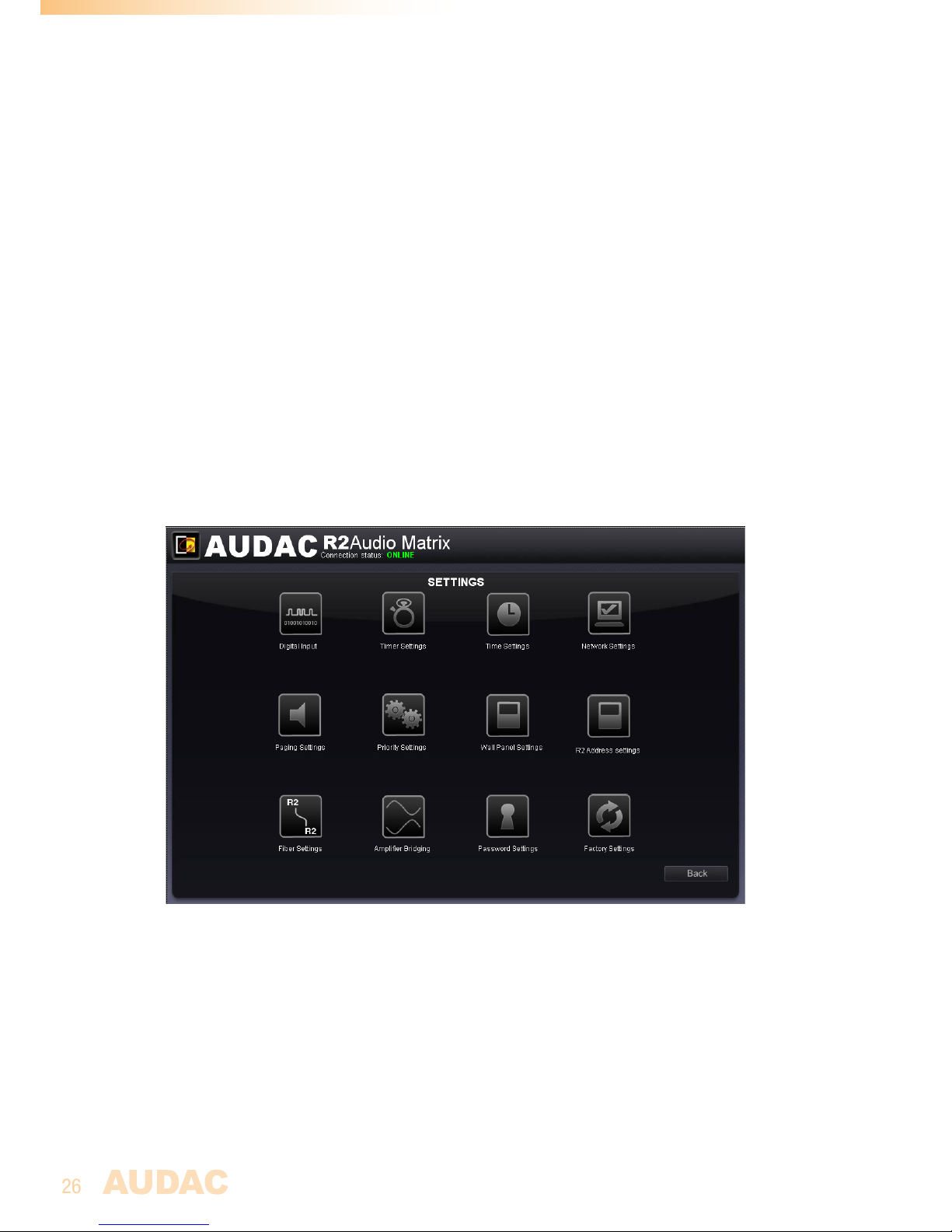
The configuration settings control panel comes up after clicking the “Setup” button.
(Only on Administrator level)
In this window, all the settings of the R2 can be made, such as selecting the desired digital
input source, changing the time settings, configuring the built-in timer, adjusting the network
settings, adjusting the paging volume, changing the priority settings, making the system
configuration for external connected devices, making the fiber settings, setting the address,
bridging the output channels, changing the password, and restoring the settings to factory
default.
If you want to change some settings, just click on the corresponding icon.
Save configuration
All configuration settings changes made in this window will be saved automatically and
are still effective after shutdown of the device.
Back
Click the “Back” button to go back to the main screen.
Settings
Back
Click the “Back” button to go back to the configuration screen.
Page 27

27
Settings >> Timer Settings
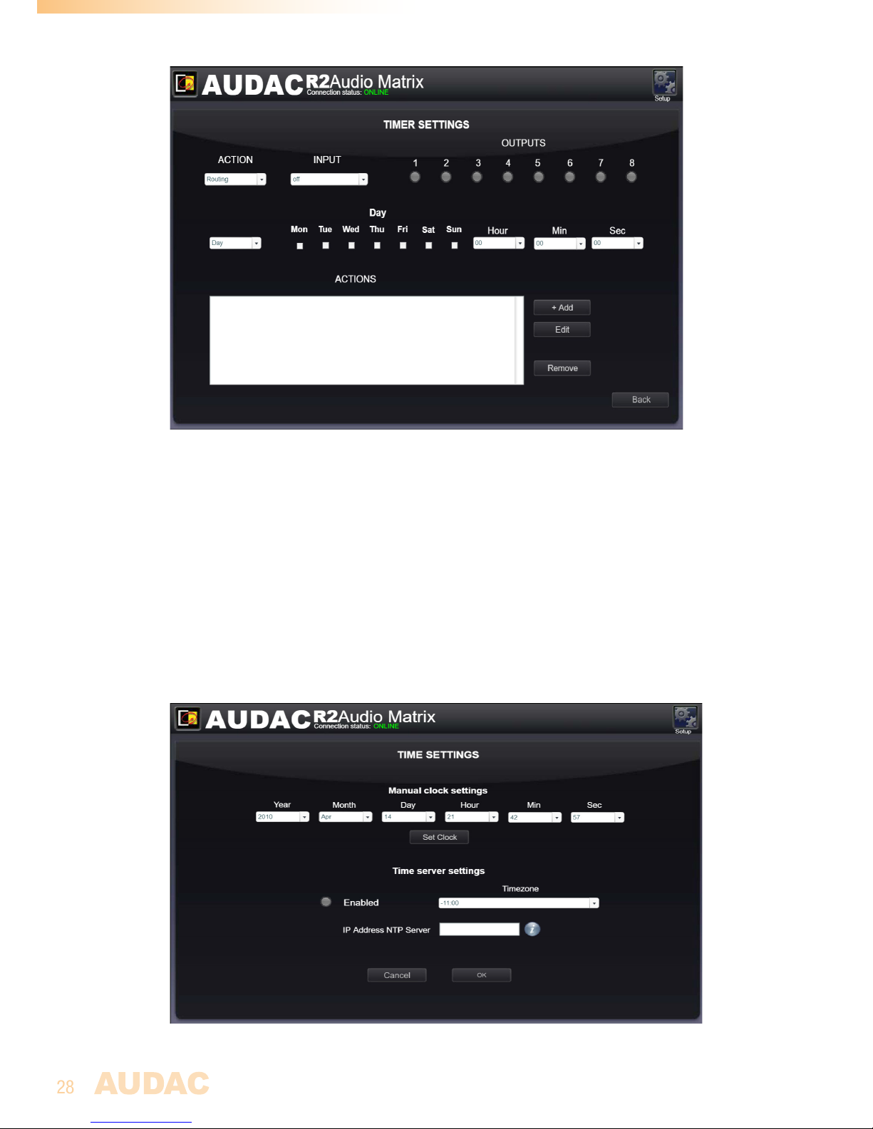
Up to 256 pre-programmed timer presets can be made in the “Timer Settings” window.
Signal routing, output volume, muting & paging volume can all be selected t at preprogrammed moments. The action which needs to be performed should be selected by
means of the “ACTION” dropdown list. To set an event at a pre-programmed moment, you
need to pass through the “Timer Settings” window.
Change Routing
To change the routing of a signal at a pre-programmed moment, select “Routing” in
the “ACTION” dropdown list, and select the input signal in the “INPUT” dropdown list.
The input dropdown list shows all the direct “CINCH INPUTS” as well as the additional
“WALL INPUTS”, (optional) “FIBER INPUTS” and special “TEST INPUTS”. By means of the
selection buttons next to the dropdown list, the output channels which should be affected
by the action can be selected. The output channels can be selected through clicking the
selection buttons. Their color will change to green when they are selected.
Change Volume
For changing the output volume of a zone at pre-programmed moments, select “Volume”
in the “ACTION” dropdown list. The amount of dB’s whereby the volume should be
adjusted to can be selected. The zone output where the volume adjust needs to take
effect on can be selected by clicking them on and off by the “OUTPUTS” section.
Paging Volume
For changing the paging volume of a zone at pre-programmed moments, select “Paging
Volume” in the “ACTION” dropdown list. The amount of dB’s whereby the volume should
be adjusted to can be selected. The zone output where the volume adjust needs to take
effect on can be selected by clicking them on and off by the “OUTPUTS” section.
Mute
For changing the mute staus of a zone at pre-programmed moments, select “Muting”
in the “ACTION” dropdown list. The zone output where the volume adjust needs to take
effect on can be selected by clicking them on and off by the “OUTPUTS” section.
Single and recurring
There can be programmed single events that only happen once, but there can also be
programmed recurring events that repeat on a weekly basis. This can be selected by
toggling the selection box between “Day” and “Date”. For single events we choose “Date”,
and then select the desired time and date by the dropdown lists. For recurring events,
click on the checkboxes for the days of the week when the event has to take place, and fill
the desired time in the dropdown lists.
To add the set actions to the time schedule, click the “Add” button and the programmed
action will appear in the “ACTIONS” window below.
For changing the events, click on the event which should be adjusted in the “ACTIONS”
window. After the desired action is selected, click the “Edit” button on the right side of the
window, and the action can be changed.
Back
Click the “Back” button to go back to the configuration screen.
Page 28
28
Timer settings
Settings >> Time settings
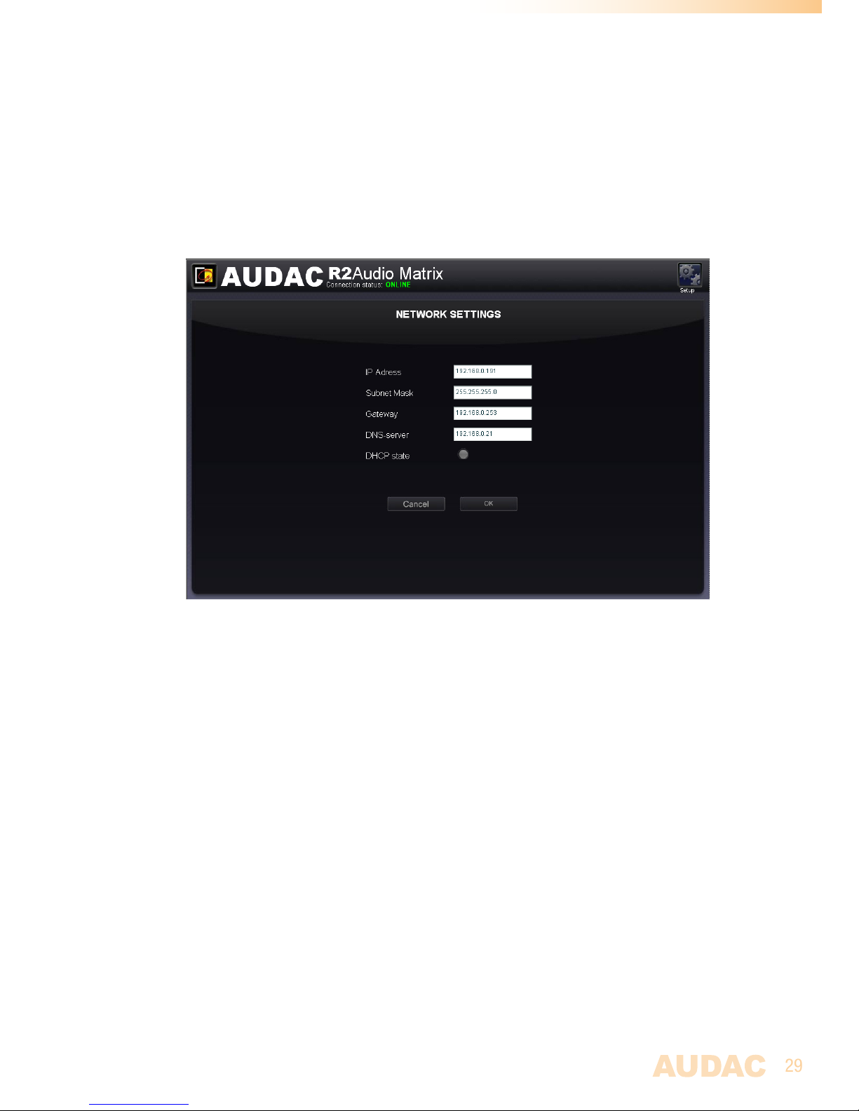
The actual time and date of the R2 can be set in this window.
This can be done on two different ways, the clock settings can be made manually by selecting
the right values from a dropdown list, or when connected to the internet, the current time and
date can be retrieved from a time server. Just select the time zone in which you are located,
and the current time and date is automatically updated by the time server.
Click the “OK” button to confirm the time settings.
Time Settings
Page 29
29
Settings >> Network settings
In this window, the network settings of the R2 can be adjusted.
The IP address is standard set to 192.168.0.191 and the subnetmask is standard set to
255.255.255.0.
Click the “OK” button to confirm the network settings.
Network Settings
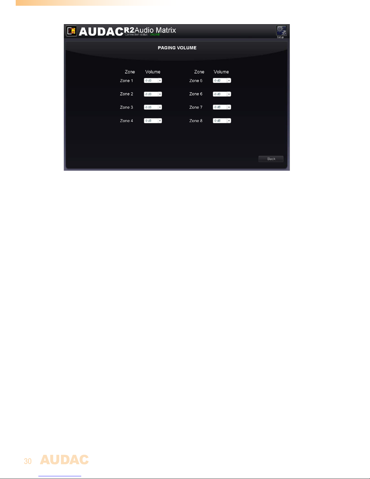
Settings >> Paging settings
In this window, the paging volume for each individual zone can be set by means of the
dropdown boxes displayed next to the zone names. The paging volume can be set in steps
of -1 dB, starting by 0 dB, going to -∞. When the volume is set to 0 dB, announcements
for the corresponding zones will be made on maximum volume.
Back
Click the “Back” button to go back to the configuration screen.
Page 30
30
Paging Settings
Settings >> Priority settings
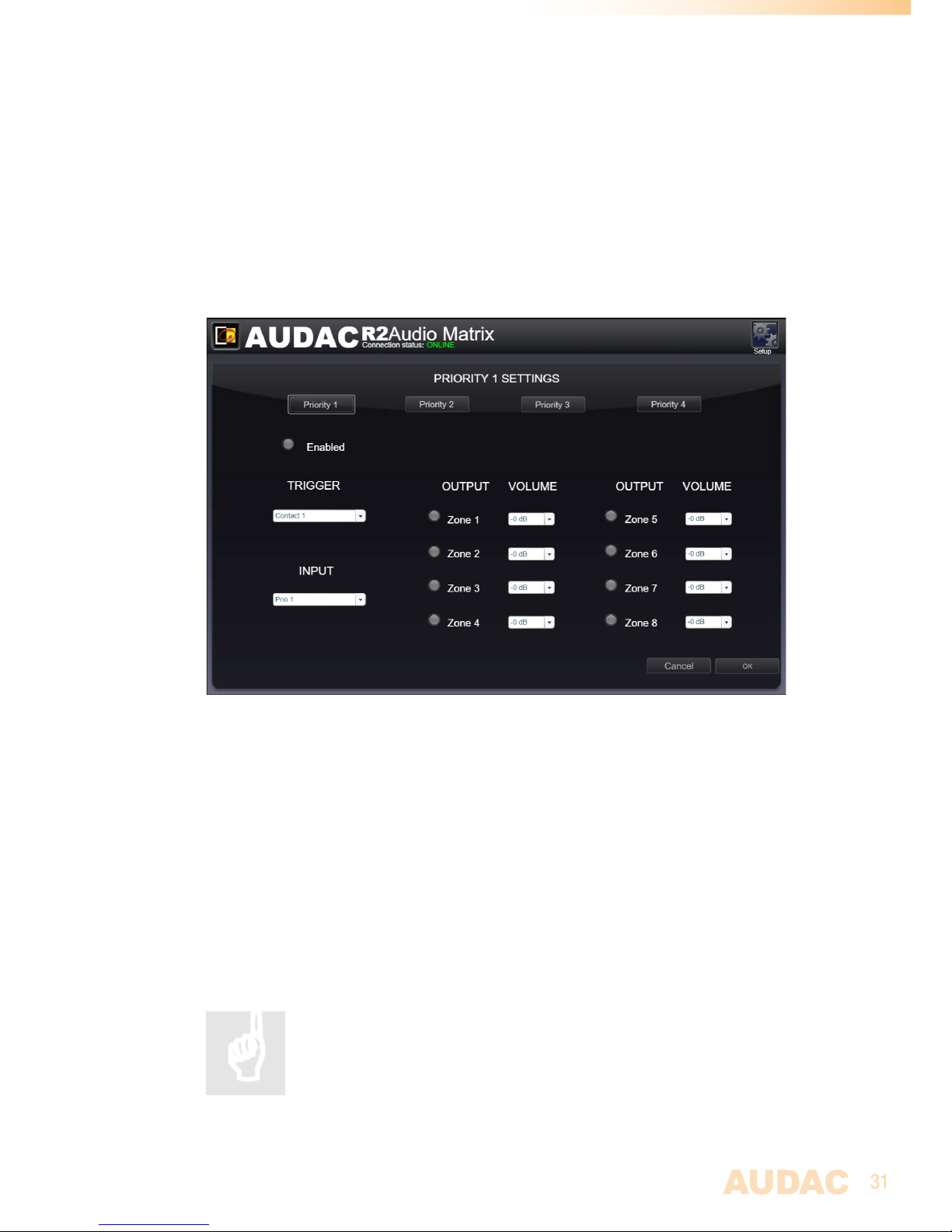
The priority settings menu makes it possible to configure the priority channels. On top of this
window, all priority inputs are displayed ranging from Priority 1 to Priority 4. The input selected
for Priority 1 has the highest level of priority, the input selected for priority 4 has the lowest.
Note: On all Audac devices, priority settings always have priority over paging.
Priority input selection
You can select the desired priority channel by clicking on the corresponding button on
top of the window, and switching them on and off can be done by clicking the “Enabled”
button. When the priority is enabled, this button will turn green.
On the left side of this window, there are a “Trigger” and a “Input” dropdown list displayed.
In the “Trigger” dropdown list are all the inputs shown on which the priority can be triggered.
This ranges from the direct line inputs to the fiber and wall panel inputs as well as the internal
test signals. In addition to these input signals four priority inputs are displayed (two priority
signal inputs and two priority contact inputs). Here you can select on which input signal the
priority needs to be triggered. When an priority audio input is selected, there will be switched
to priority when an audio signal is present on these inputs. When a contact input is selected,
there will be switched to priority when a contact is made between those two pins.
In the “Input” dropdown list below, there can be selected which input signal has to be patched
when a priority situation occurs. In this list, the two direct priority audio inputs, the regular
direct RCA inputs, the Wall panel inputs, the Fiber inputs, but also the DSP and other input
signals are displayed.
On the right side of the window is a list of all output channels displayed. In this list can be
selected to which output zones the priority channel needs to be patched. This can be done
by simply clicking the button next to the channel. When the priority signal for this zone is
enabled, the button will turn green.
Page 31
31
Next to every output zone is a dropdown list displayed whereby the volume can be selected
in steps of -1dB.
The switching to and from a priority signal is done according to the HARDIN - FADEOUT
principle. This means when a priority situation occurs (signal present on the priority audio
inputs or connection between priority input contacts) , immediately will be switched to the
selected priority action. When the priority situation is over (no more signal present on the
priority audio inputs or no more connection between the priority input contacts), the status
of the R2 will return to the previous status by fading the sound in.
Click the “OK” button to confirm the priority settings.
Priority Settings
Settings >> System configuration
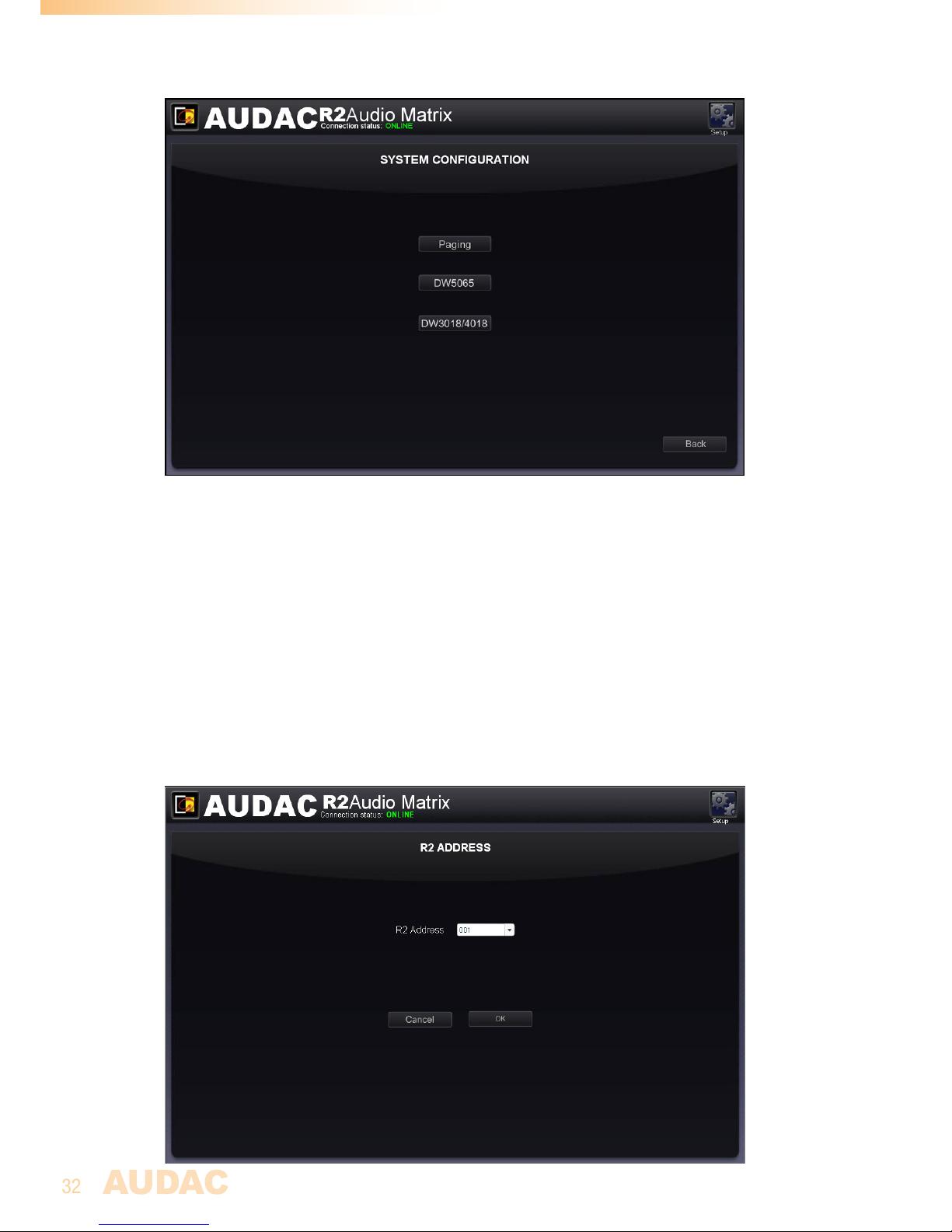
In this window, the configuration settings for external connected devices such as paging
consoles and wall panels can be made. This window shows three buttons, each of them
for configuring one kind of external connected devices. Click the ‘Paging’ button when the
configuration for the APM1xx paging consoles has to be made, while the ‘DW5066’ button
enables to configure the settings for the All-in-one wall panels, and the ‘DW3020/4020’
enables you to configure the settings for the basic wall panels.
Just click the corresponding button to proceed to the settings menu.
For more information about the connection and configuration possibilities
for external connected devices, refer to Chapter 6: Peripheral
Interfaces of this user manual. In this chapter is extensively described
how the connection and configuration for peripheral equipment should
be done.
Back
Page 32
32
Click the “Back” button to go back to the configuration screen.
System configuration
Settings >> R2 Address settings
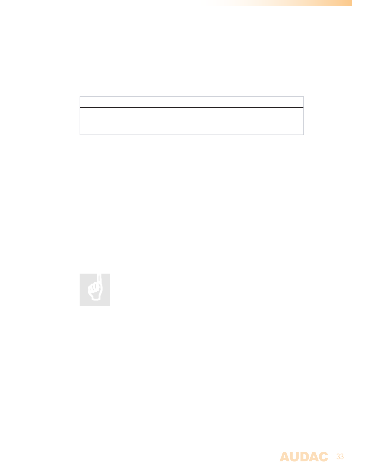
In this menu, the address of the R2 can be set. This address is factory default set on
“001” and is selectable between “001” and “099”. When only one R2 is available, the
default address can be left to its default value.
When more R2’s are cascaded through the fiber interconnection bus, there needs to be
assigned a unique address for every R2. The first R2 starts with address “001”, and every
subsequent R2 should be assigned an address with a higher value.
Click the “OK” button to confirm the address settings
Page 33
33
Address Settings
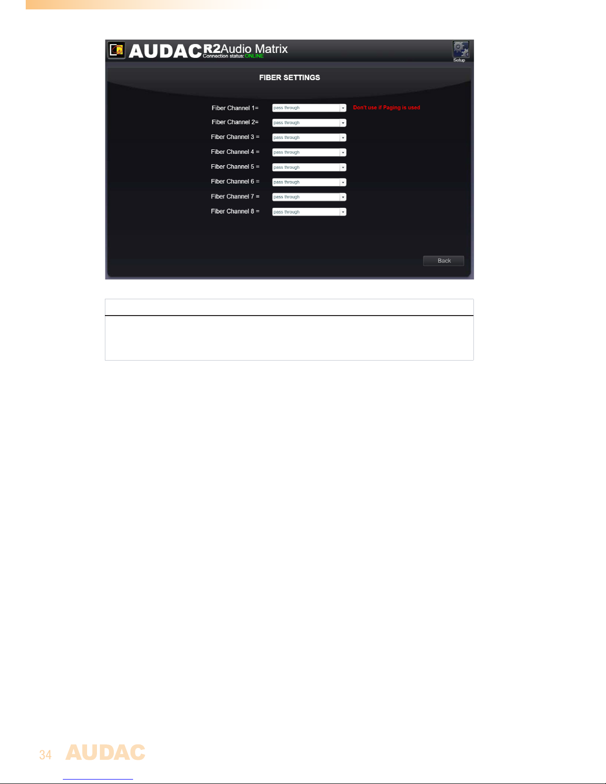
Settings >> Fiber settings
In this window can be set which audio signals of the R2 should be transmitted over the fiber
interconnection interface.
NOTE
The fiber interconnection interface is an optional module for the R2. (OPT2)
The settings which are made in this window will only affect when the internal fiber
interconnection interface of the R2 is installed.
The software of the R2 matrix supports to transfer up to 8 stereo channels over the fiber
interconnection interface.
In the “Fiber Settings” window of the web based user interface is an overview given of all
the channels which can be transmitted over the fiber interconnection interface, numbered
from “Fiber Channel 1” to “Fiber Channel 8”. Next to each channel is a dropdown list
displayed where can be selected which of the audio channels should be transmitted over
the corresponding fiber bus channel.
In this dropdown list are all direct line inputs, all wall panel inputs, all priority inputs and all
additional DSP generated signals displayed.
When an audio channel should be transmitted over a fiber channel, simply click the audio
channel in the dropdown list of the desired fiber channel.
Click the “Back” button to go back to the configuration screen.
For more information about cascading the R2 and the fiber
interconnection interface, refer to Chapter 8: Cascading the R2 of this
user manual.
Page 34
34
Fiber Settings
NOTE
When paging is send over fiber, the audio from the APM table will be Temporally place
onto fibre channel one, it is recommended no to use this channel is paging across
device is also used.
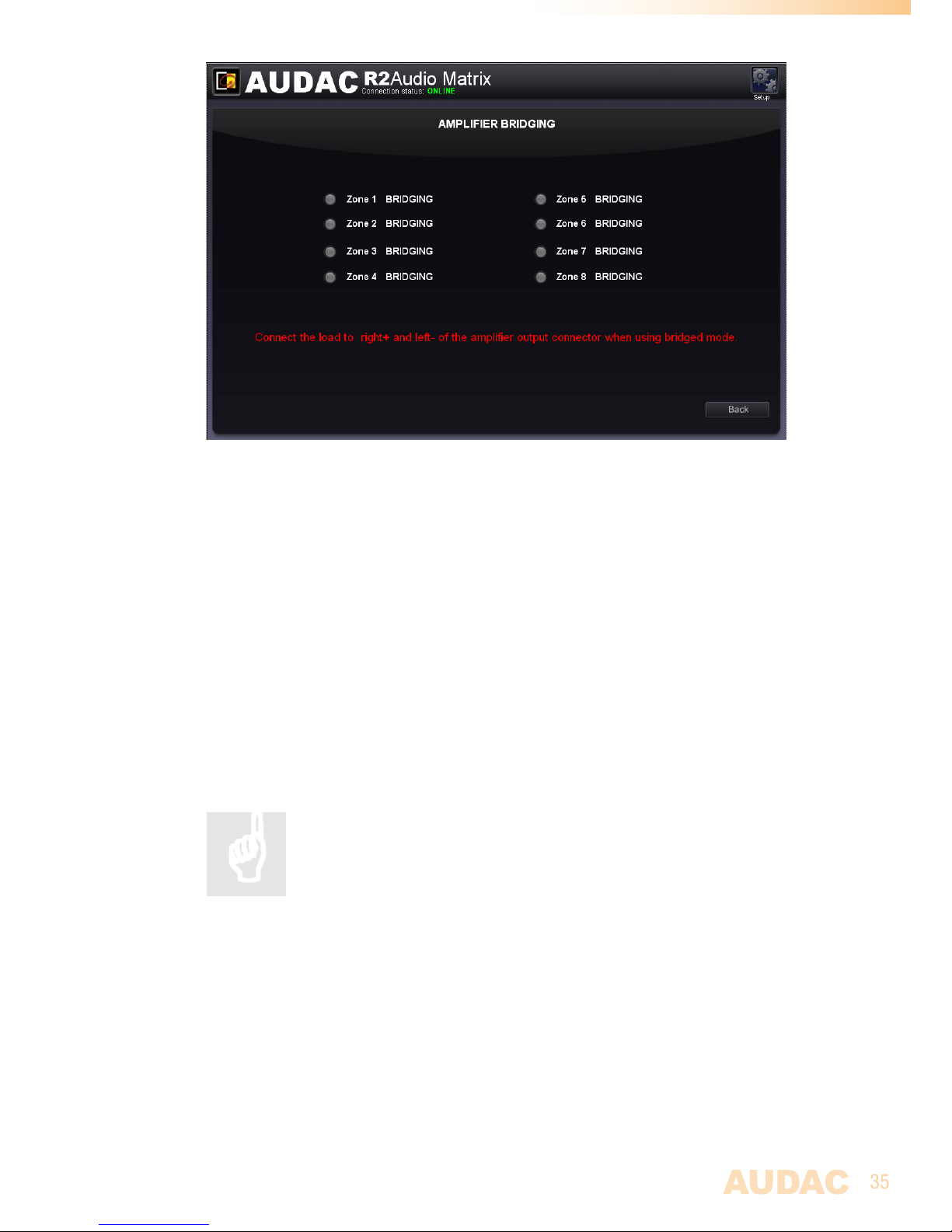
Settings >> Amplifier bridging
Just click on the button corresponding with the zone,will set the output of that zone to mono.
which you can then bridge the output on the back side on the R2, the amplified Left and
Right output channels, become of 120Watt @ 8 ohm.
(Only when the POW2 power amplifier kit is installed).
When the bridging function is turned on, the “LEFT” input signal will used for both left and
right output signals. The loudspeaker should be connected between the + terminal of the
right channel and the - terminal of the left channel.
Click the “Back” button to go back to the configuration screen.
Page 35
35
Amplifier Bridging
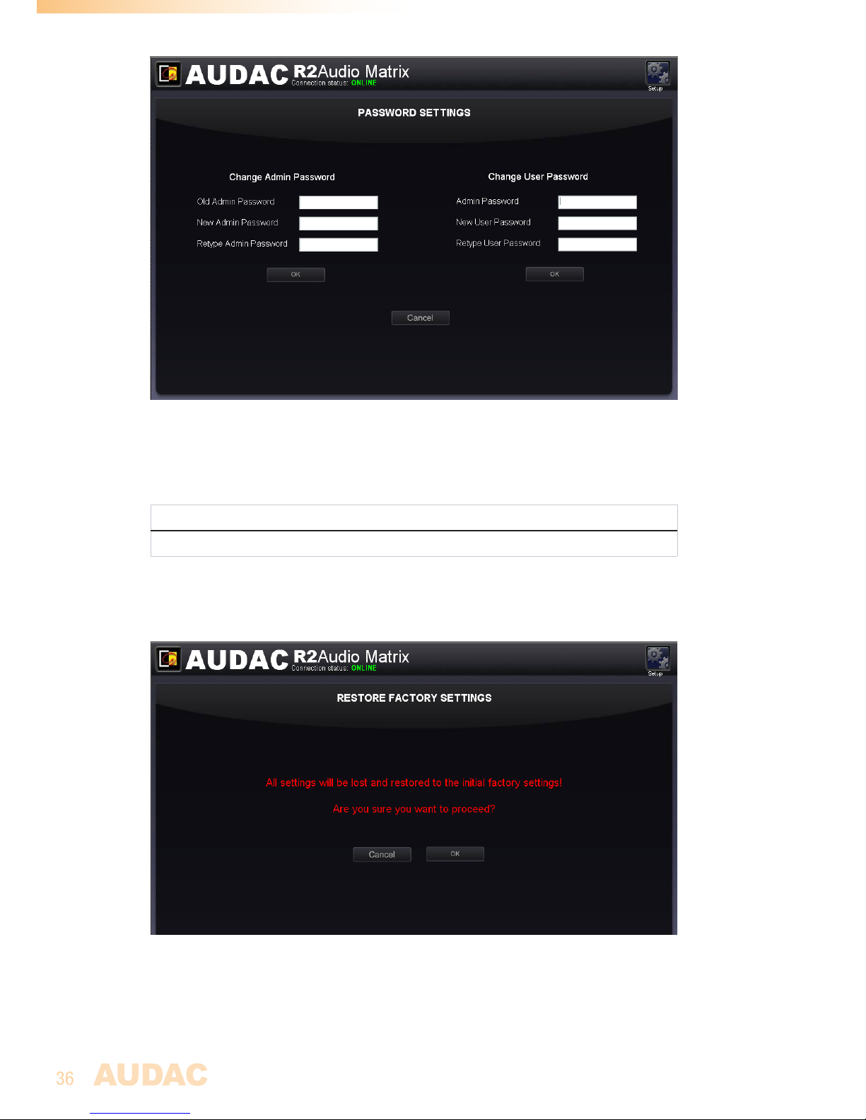
Settings >> Password settings
In this window the passwords for the R2 can be changed. There are two different password
levels. Administrator level which has full access to all functions and User level, which has
only access to the basic functions.
On the left side of the window the settings for the Administrator password can be changed,
while on the right side the settings for the User password can be changed.
For changing the password, enter the old password in the provided field, and enter the new
password twice in the provided fields. After this all is completed, push the “OK” button.
When the old password is correct, and the new password filled in both fields match, the
old password will be changed into the new password.
The factory default password for Administrator level is “R2” and for
User is “User”.
Page 36
36
R2 Password Settings
Settings >> Factory settings
ATTENTION
BE CAREFUL to press this button. It really will recall the ORIGINAL factory settings !!!
It does not recall the previously saved settings, but it recalls the original factory setting
and the previously made settings will be lost.
Click the “OK” button to reset the settings to factory default.
Restore Factory Settings
Page 37

37
Chapter 5
Peripheral interfaces
The R2 offers the possibility to connect many additional input and control units in addition
to the standard direct line inputs.
To connect those additional units, peripheral interface ports are provided on the rear side
of the R2. In the further explanations of this user manual, we will refer to the peripheral
interface ports (RS485) with the letters “PI”, followed by a number ranging from 1 to 10,
each representing one PI port on the rear side of the R2. As this already suggests, there
are 10 PI ports available on the rear side of the R2, each of them performed with an RJ45
connector. 8 of these PI ports are capable of transporting bidirectional audio and data
(ports PI 1-8), while the remaining two ports are only capable of transporting data (ports
PI 9-10).
Devices possible to connect to the PI ports:
DW3020/4020 Basic wall panel with routing and volume control
Multiple DW3020/4020 wall panels can be connected in a bus structure. This wall panel
is only using digital data transfer and no audio transfer, so it can be connected to all
peripheral interface ports from PI1 to PI10. The assignment of the wall panel with a zone
should be done in the user interface.
DW5066 Advanced wall panel with graphic display stereo line input and
microphone input
This wall panel can control multiple zones and has a direct digital audio link to the R2.
Only one DW5066 wall panel can be connected on one PI port, and only PI1 to PI8 can be
used for connecting DW5066 wall panels.
APM Paging system
The APM paging system can be used to page to different paging zones of the R2. Paging
to zones on other R2’s is also possible when multiple R2’s are linked with each-other
through the (optional) fiber interface OPT2.
APM paging consoles can only be connected to PI ports PI1 to PI8. Multiple APM paging
consoles can be connected to one PI port, using a bus structure with ARJ03P junction
boxes. When multiple APM paging consoles are connected to one PI port, only one APM
console can announce messages at a time, so the paging is priority based. Paging with
different APM consoles in different zones is possible when the APM’s are connected to
separate PI inputs.
Page 38
38
Connection possibilities
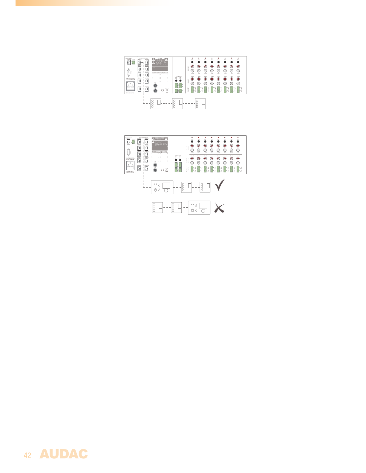
Working connections:
- Multiple DW3020/4020’s on one PI input (PI1 to PI10)
- One DW5066 and multiple DW3020/4020’s to one PI input (PI1 to PI8)
- One APM and multiple DW3020/4020’s to one PI input (PI1 to PI8)
- Multiple APM’s (priority) and multiple DW3020/4020’s to one PI input (PI1 to PI8)
Connections that don’t work:
- DW5066 and APM to one PI input
- DW5066 to PI9 or PI10
- APM to PI9 or PI10
- Multiple DW5066 to one PI input
Important
Always make sure the R2 is powered off when connecting or
disconnecting devices to the PI ports.
When an audio signal is transmitted to the peripheral inputs from an
external input device (e.g. DW5066 wall panel or APM paging console)
the used cabling should always be UTP/FTP CAT6 cable or better.
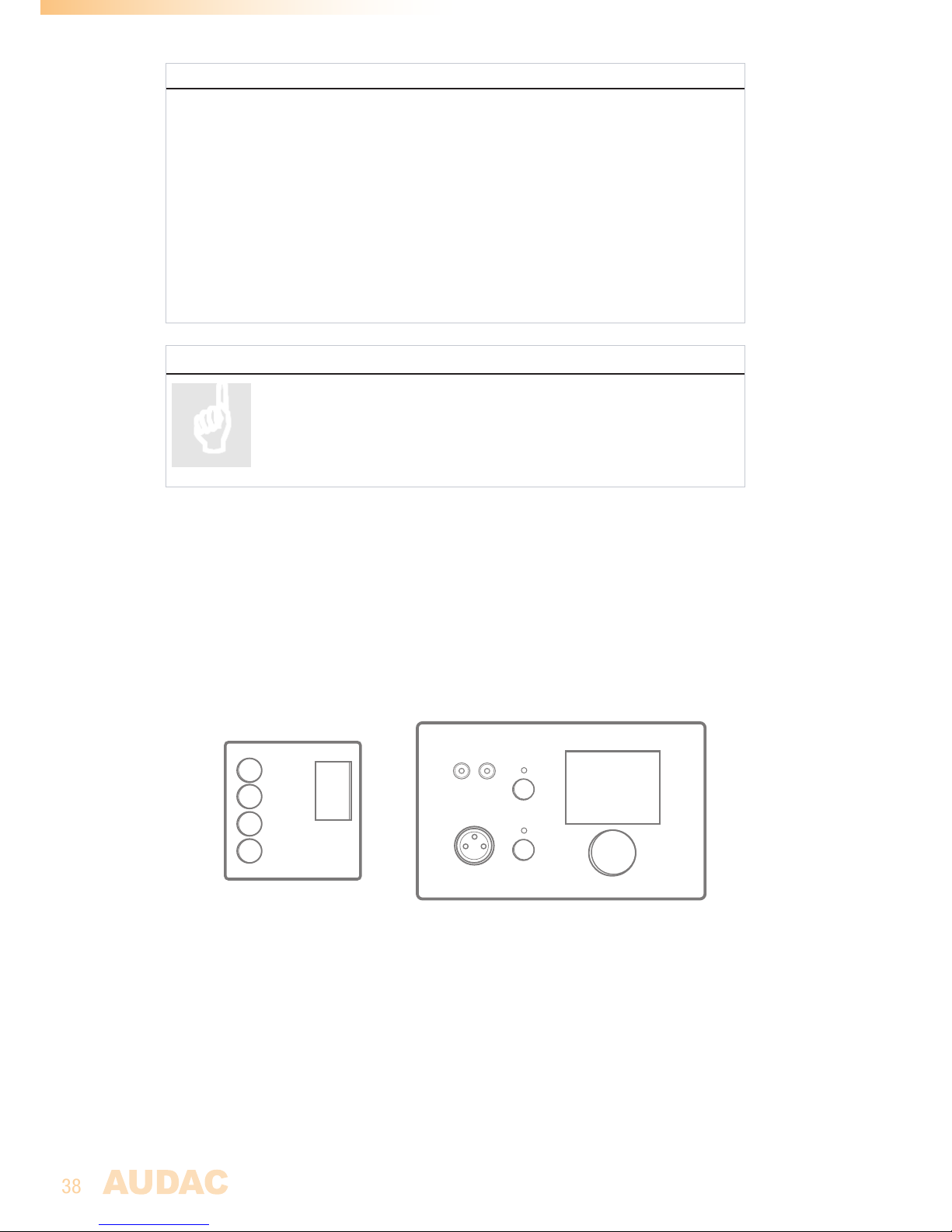
Wall mounted control panels
The R2 installation can be expanded with additional wall control panels. There are two kinds
of wall panels available, one standard wall panel (DW3020/4020) which allows to adjust the
routing and volume for a particular output zone, and one All-In-One wall panel (DW5066),
which provides the possibility to connect an additional Line of Microphone signal source in
a specific zone.
DW3020/4020 (Left) & DW5066 (Right) Wall panels
The wall panels should be connected with the peripheral ports on the rear side of the
R2, by means of Twisted pair UTP/FTP CAT5 (or better) cabling for DW3020/4020 and
UTP/FTP CAT6 (or better) cabling for DW5066. It is possible to connect multiple standard
(DW3020/4020) wall panels on one single peripheral port (Up to 32 wall panels according
to RS485 specification). Only one All-In-One wall panel with audio inputs (DW5066) can
be connected to each peripheral port.
Prog.
Vol
+
-
+
-
AUDAC
LINE IN
MIC IN
Page 39
39
DW3020/4020 Basic wall panel
Functions
The DW3020/4020 is the basic wall panel which allows to control the routing and the
volume of the R2. A selection out of up to 8 input signals can be made by means of the
DW3020/4020 wall panel. The inputs which are selectable by means of the wall panel can
be configured in the user interface under ‘Zone settings’ and ‘Input Selection’. How this
works is extensively described in an earlier chapter of this user manual. First read the PI
connection principles in the beginning of this chapter before making any connections.
Change routing
In normal conditions, the DW3020 display will show the routing by indicating the number
of the selected input signal which is routed to the related zone. If the “Prog +” button is
pressed, the next pre-defined input will be selected, if the “Prog -” button is pressed,
the previous pre-defined input will be selected.
Change volume
The volume in the corresponding output zone can be changed by pressing the “Vol +”
and “Vol -” buttons. Logically, the volume will be increased after pressing the “Vol +”
button will be decreased after pressing the “Vol -” button. When the volume is changed,
the display will show the volume level for two seconds, and after those two seconds, the
routing will be displayed again.
Configuration
Before the DW3020/4020 wall panels can be used, the wall panels needs to be assigned
to one particular zone. Perform the procedure described below to make sure this is done
correctly.
Go to the “Setup” menu and click “System configuration”. Now you have the possibility
to choose between “Paging”, “DW5066” and “DW3020/4020”. To configure the settings
for the DW3020/4020 wall panels, click the corresponding button. Now a window with a
dropdown list is shown, displaying all the available zone names. Select the zone whereto
a wall panel should be assigned, and click the ‘Set Address’ button. All connected wall
panels will start blinking, and after pressing the upper button on the desired wall panel,
it will be linked to the selected output zone. If multiple wall panels should be assigned to
one zone, simply repeat this action.
Maximum cable length
The maximum cable length depends of the number of connected wall panel. When only
one wall panel is connected, a maximum cable length of 600 meters can be reached. The
table below gives an overview of the maximum cable length, depending of the connected
wall panels.
No. of DW3020/4020 Wall panels Maximum cable length
1
2
3
4
5
6
7
600 meter
600 meter
400 meter
300 meter
200 meter
150 meter
120 meter
Page 40
40
DW5066 All-in-one wall panel
Functions
The DW5066 is the advanced All-in-one wall panel for the R2. This wall panel has a
graphic display and can control the routing, volume, bass, treble and mute for multiple
zones (up to 8) on one R2. Besides those control functions, it also provides the possibility
to connect a microphone and a stereo line input source. The DW5066 wall panel should
be connected to the R2 by means of a UTP/FTP Cat6 (or better) cable. First read the PI
connection principles in the beginning of this chapter before making any connections.
The following functions of multiple zones of the R2 can be controlled:
- Volume within a range of 0dB to -70 dB
- All inputs can be selected
- Mute can be activated
- Bass within a range from -9dB to +9dB
- Treble within a range from -9dB to +9dB
Configuration
Before the DW5066 can operate, the configurations should be made. First of all, an
address need to be assigned and the available inputs need to be defined.
Follow these steps to configure:
1) Go to the “Setup” menu and click “System configuration”. Now you have the possibility
to choose between “Paging”, “DW5066” and “DW3020/4020”. To configure the settings
for the DW5066 wall panels, click the corresponding button. Now a window is displayed
which provides all the configuration possibilities for the DW5066. On the left side, a
dropdown list is displayed whereby the address for the DW5066 can be selected. The
address can be selected between “W001” and “W008”. Logically, you start with address
“W001” for the first wall panel, and increases for every additional wall panel. After the
desired address is selected, click the “Set address” button. After this button is pressed,
the DW5066 will start blinking. To confirm the selected address with the wall panel,
click the big rotary button on the front of the wall panel. When this button is pressed, the
address will be assigned to the selected wall panel.
NOTE
It is recommended that when assigning the DW5066 an address the number matches
the socket location on the back side of the R2. In this was W001 will also represent
RS485(1)
2) The zones which you want to control with the selected wall panel can be selected by
means of the “Controlled zones” dropdown list. When selecting a zone in this dropdown
list, the zone name will appear in the listbox below. The zones can be removed again from
this listbox by selecting them, and clicking the “Remove Zone” button.
3) The inputs which are selectable with the selected wall panel can be selected by means
of the “Selectable inputs” dropdown list. All inputs which available on the R2 can be
selected in this dropdown list, such as the direct line inputs, the peripheral inputs, the
fiber inputs, the priority inputs and the integrated DSP signals. When selecting an input
signal in this list, the signal name will appear in listbox below. The input signals can
Page 41

41
be removed again from this listbox by selecting them, and clicking the “Remove Input”
button. A maximum of 24 signal inputs can be selected. The inputs which are selected in
this listbox, are available for all zones which can be controlled by this DW5066 wall panel.
Those inputs are not linked with the quick menu like the inputs on the DW3020/4020 are.
4) Certain actions such as Volume change, Input change, Mute change, Tone control
change and settings change can be blocked by checking the checkboxes.
5) The microphone input has the possibility to provide +15V phantom power for powering
condenser microphones. The phantom power can be switched ON and OFF by clicking
the “Enable Mic Phantom” checkbox. This setting can also be changed in the DW5066
settings menu. (If “Block settings menu” is not checked)
6) The Backlight level, screensaver and screensaver delay can be set by means of three
dropdown boxes. This setting can also be changed in the DW5066 settings menu. (If
“Block settings menu” is not checked)
7) When the settings are made, press the “Save to Wallpanel” button and the settings will
be send to the selected DW5066 wall panel.
Previously made settings can be retrieved from the wall panel by clicking the “Load from
Wallpanel” button. Hereby, the settings which are stored in the wall panel will be displayed
in this window, making it possible to make any changes to the current settings.
Maximum cable length for DW5066
The maximum cable length for the DW5066 wall panel is 300 meter.
Page 42
42
Connection possibilities
Prog.
Vol
+
-
+
-
Prog.
Vol
+
-
+
-
Prog.
Vol
+
-
+
-
Multiple DW3020/4020 Wall panels on one PI Port (PI1 to PI10)
AUDAC
LINE IN
MIC IN
Prog.
Vol
+
-
+
-
Prog.
Vol
+
-
+
-
Multiple DW3020/4020 and one DW5066 Wall panel on one PI Port (PI1 to PI8)
Connecting one or multiple DW3020/4020 in front of the DW5066 wall panel will cause problems.
AUDAC
LINE IN
MIC IN
Prog.
Vol
+
-
+
-
Prog.
Vol
+
-
+
-
Page 43
43
Chapter 6
Paging
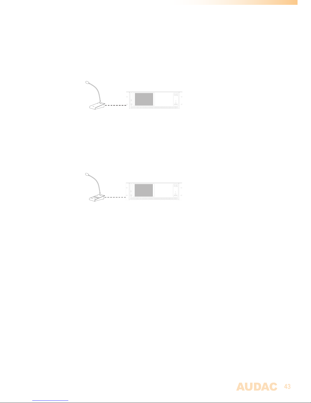
1 Zone paging example
The most basic example of an R2 paging system is an R2 audio matrix, in combination
with an APM101MK2 paging console. This setup makes it possible to announce messages
in 1 or more pre-defined zones, and with a pre-defined volume for every zone.
8 Zone paging example
A second paging example of an R2 paging system is an R2 audio matrix, in combination
with an APM108MK2 paging console. The difference between the previous example (with
APM101MK2) are the amount of paging zones. The APM108MK2 console contains 8 zone
selection buttons, which makes it possible to page separately to all zones, or to page to
multiple zones at a time.
Priority
Paging is always priority based. When multiple APM consoles are connected to one R2,
and multiple APM’s give a command to announce a message at the same time, it depends
of the priority settings which message will be announced. The priority level is related to
the address of the APM table by default but this is configurable.
For voice files and messages which are stored inside the APM memory, the priority works
differently. A priority number can be assigned to each stored message, making it possible
to give emergency messages a higher priority.
Connection possibilities
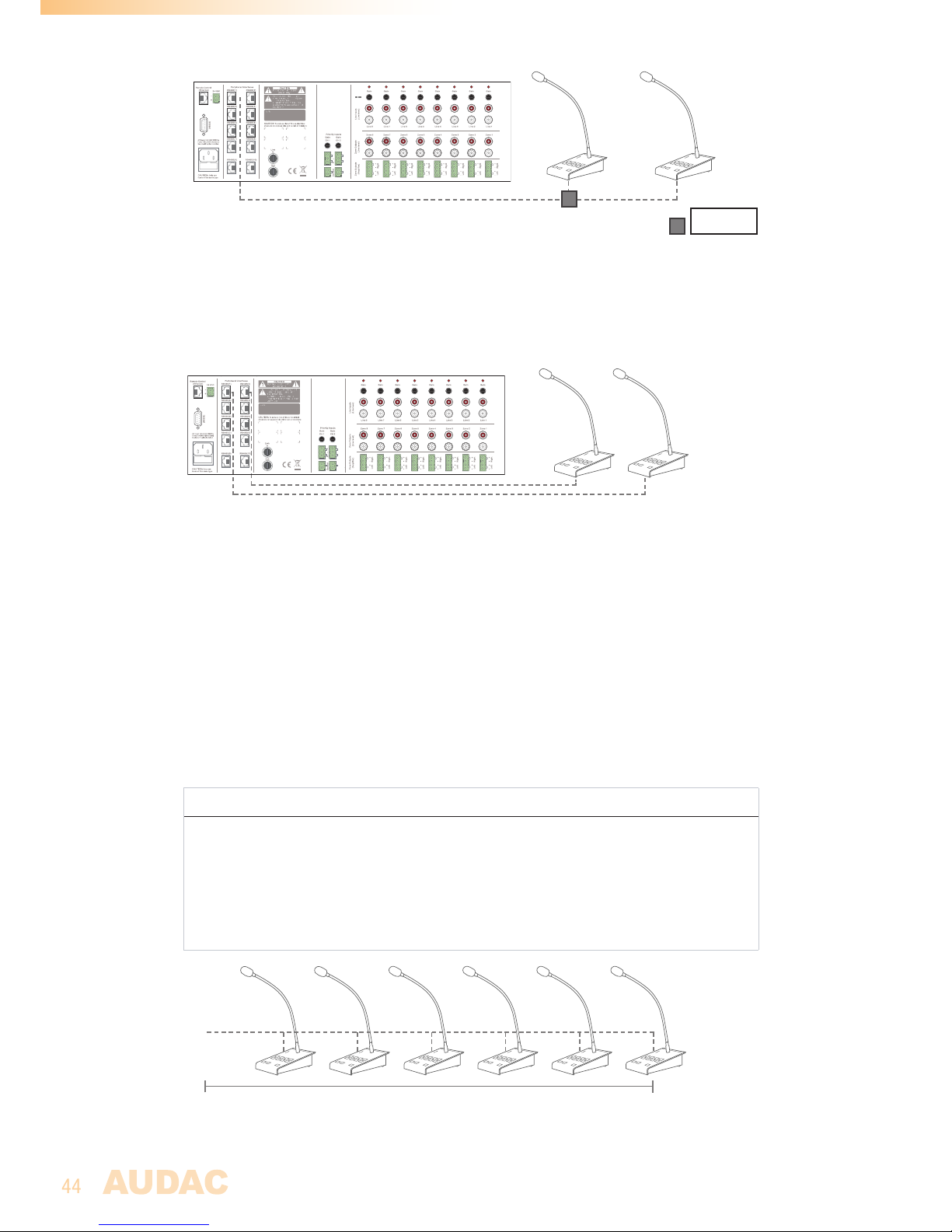
Two different connection methods are possible for connecting multiple APM’s to one R2.
1) Bus structure
Multiple APM’s can be connected in a bus structure, on the same PI Input. Only one APM
paging console is able to page at a time, so this is always priority base.
Page 44
44
2) Separate PI input
Multiple APM’s can be connected to the R2, each of them using a separate PI Input. If the
selected paging zones are different, paging to different zones can be done at the same
time. If multiple APM’s are trying to page to the same zone at the same time, then paging
is priority based, and only the message coming from the APM with the highest priority
(lowest address) will be announced.
Paging over fiber
When multiple R2’s are cascaded with each other through the fiber interconnection
interface, paging messages can be transferred over the fiber conductor, making paging
possible in multiple zones of multiple R2’s. When this option is enabled, audio channel
one (FB1) is dedicated for paging purposes, whereby this channel can’t be used for other
purposes.
Paging over fiber is always priority based, and only one APM can page to multiple R2’s at
the same time.
Limits
When multiple APM’s are connected on one PI port using a bus structure, a maximum of 6
APM’s can be connected to one PI port, with a maximum cable distance of 300 meter for
the total APM bus.
Connection limits summary
- Maximum 9 APM’s on one PI port
- Maximum 72 APM on one R2
- Maximum 300m when Cat 6 cable is used
- Always use ARJ03P junction boxes with external power supply when multiple APM’s
are connected using Bus structure.
- Use CP43ARP when distance exceed 300m
Bus
Max 300 meter
ARJ03P
Page 45
45
Configuration
To make the entire paging system work acording to the needs of your project, a
configuration procedure should must be followed.
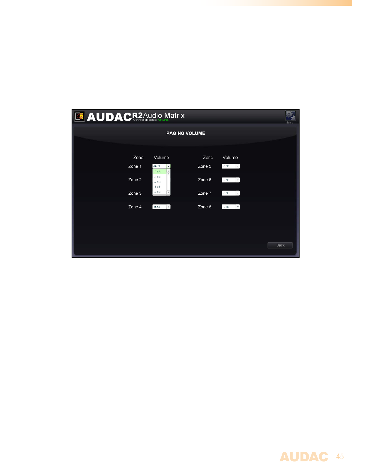
Paging volume
The paging volume can be different for every zone, and should be configured individual
for each specific zone. To configure the paging volume, go to the “Setup” menu, and click
the “Paging volume” button. By means of dropdown boxes, the paging volume for every
specific zone can be set. Any changes must be saved.
APM configuration
The paging settings are stored inside the APM’s internal memory. For configuration, the
APM should be connected to the R2, and the configuration should be done through the
web based user interface of the R2 or via the Audac system manager. You can find the
paging configuration settings in the “Setup” menu, under “System configuration”, and
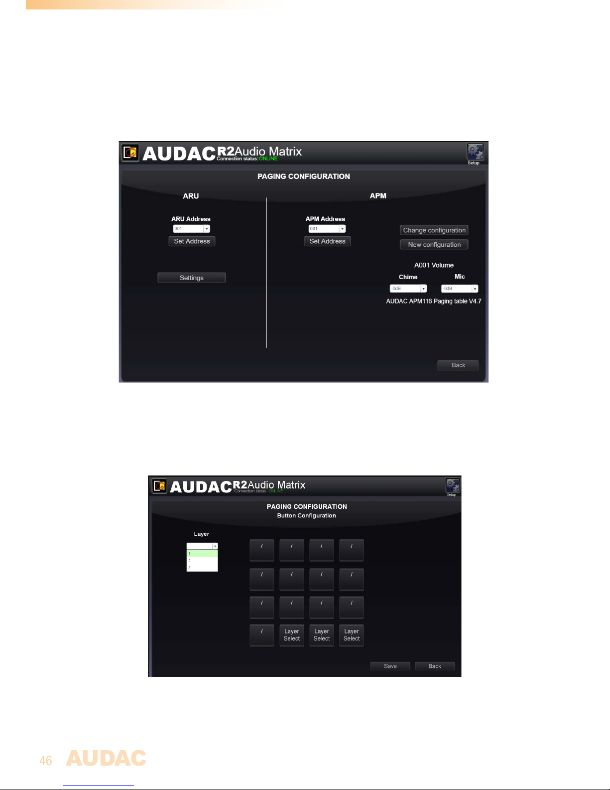
“Paging”. On the left side of the window are the settings for configuration of ARU’s shown,
while on the right side the settings for configuration of the APM’s are shown. Follow the
procedure below to make your paging system work successful.
1) Select the address which you want to assign to your paging console.
Select the address by the dropdown box, and click the “Set Address” button. Now, the
“PTT” (push to talk) button on all connected APM’s will start blinking. After pushing the
“PTT” (Push to talk) button the address will be assigned to the selected APM. For more
information regarding the APM address, see “Priority in chapter 6”.
When multiple APM’s are connected to one R2, it’s better to assign an unique address to
every APM, before continuing with the configuration procedure.
2) Select the APM and the amount of layers (only applicable for or APM116MKII)for your
configuration.
Press “New Configuration”. After pressing this button, you will be redirected to a new
window where you can select which APM you want to configure. Two dropdown boxes
are shown, by means of the upper one the R2 whereto the APM is connected should be
selected. When only one R2 is used, only “R001” will be shown. By the lower dropdown
Page 46
46
list, the peripheral port on which the APM is connected can be selected, ranging from
RS485(1) to RS485(8). When APM108MK2 or APM116MK2 are connected, the number
of layers for your APM configuration can be determined by means of the dropdown list on
the right side of this window.
When the desired APM (and the amount of layers) is selected, click the save button, and
you can proceed to the next window.
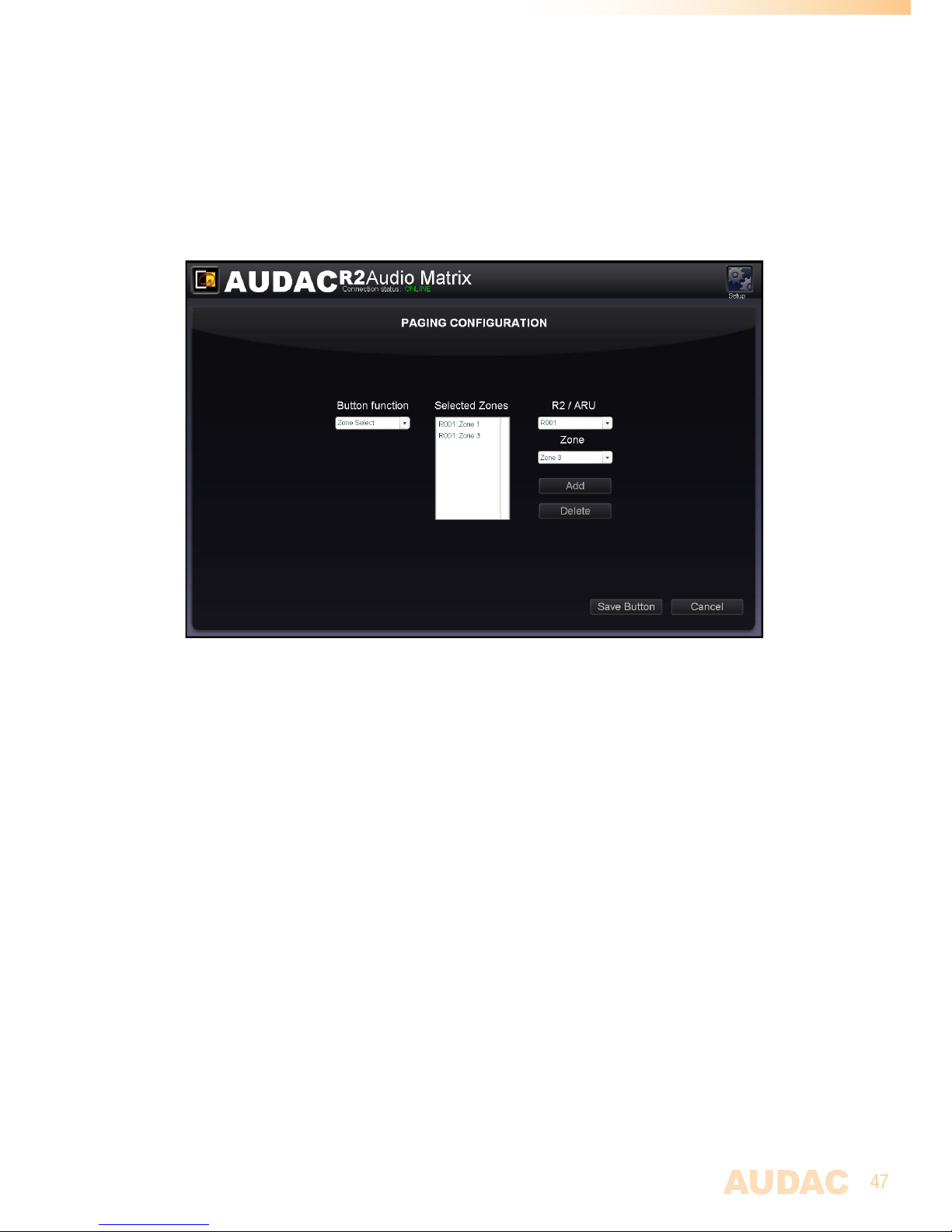
3) Configure the APM buttons
This window gives an overview of your APM keypad. The number of buttons displayed in
this window depends of the type of APM which is connected to your system. On the left
side, a dropdown list allows you to browse between the layers (when available).
Just click the button to which you want to assign a function.
After this button is clicked, a windows comes up allowing you to select the function which
should be performed after pressing this button. The available functions shown in the
dropdown list on the left side are “Zone Select”, “Play Message”, Toggle Relay and Pulse
Relay.
Page 47
47
Zone Select:
This function should be selected when the button is meant for paging purposes. The
zones where the message should be audible after pressing the button are displayed in
the “Selected Zones” listbox. Zones can be added to this listbox by selecting them in the
two dropdown lists on the right side followed by clicking the “Add”’ button. Zones can be
removed from this listbox by selecting them, and clicking the “Remove” button. Up to 40
zones, from 5 cascaded R2’s can be programmed under one button.
Play message:
By means of this function, messages stored in the APM memory, such as emergency
or commercial announcements can be announced. The stored messages are shown in
the “Message” dropdown list from where the desired message can be selected. The
priority of the message is based on the priority number which can be set in the “Priority”
dropdown list, and is not related with the APM priorty. This way, high-priority emergency
messages can be played with a low-priority APM.
The lower the priority number is, the higher the priority of the related message.
Page 48
48
Chapter 7
Cascading the R2
This chapter explains the fiber interconnection possibilities between several R2 matrixes,
and guides you through a setup process of a project with 5 R2’s cascaded with each other
by means of the fiber interconnection interface.
Principle
The (optional) fiber interconnection interface makes it possible to transfer 8 stereo audio
signals and one data channel over one single fiber optic conductor. The data channel
is transmitted automatically and can’t be configured by the user. The 8 stereo audio
channels which should be transfered over the fiber conductor can be configured by the
user.
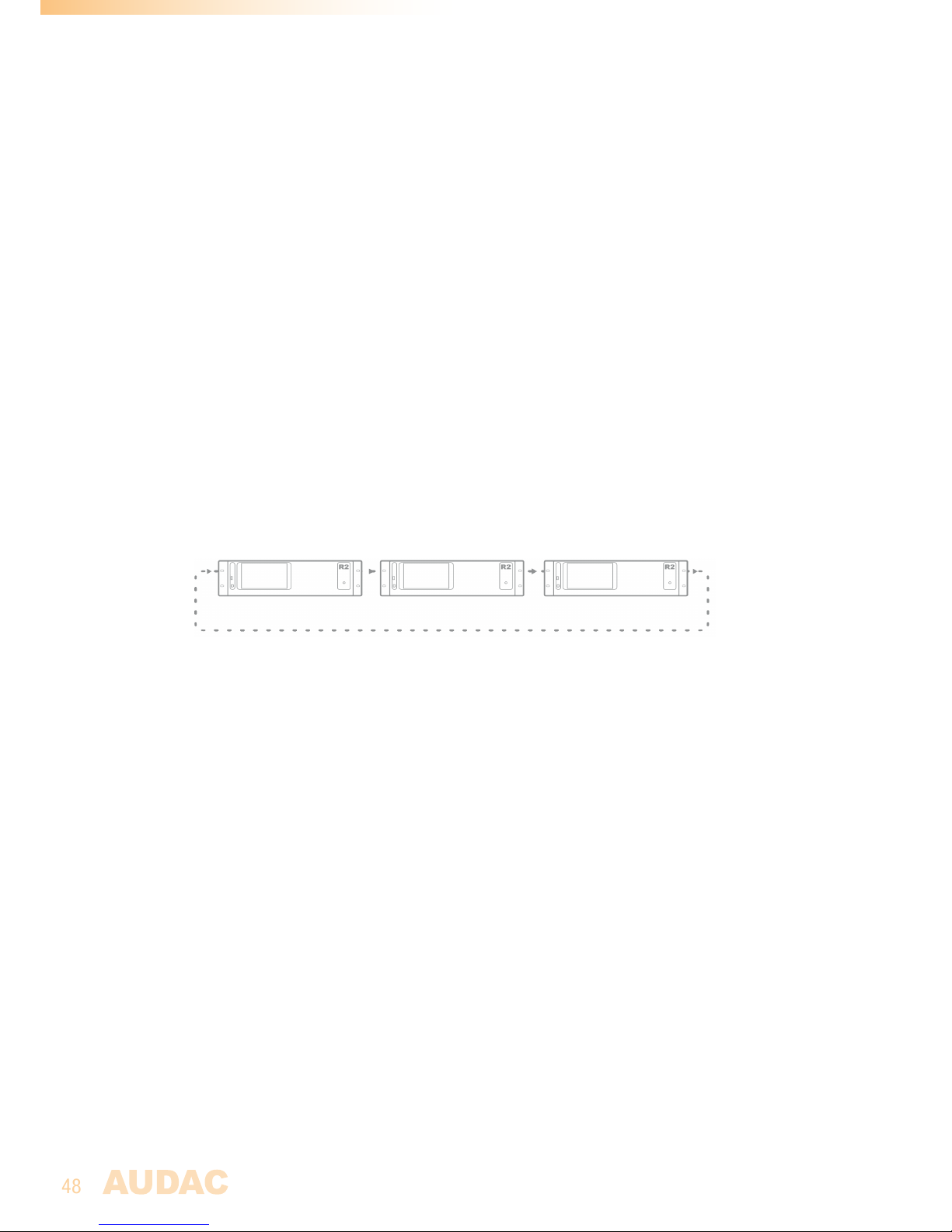
The fiber interconnection interface of the R2 works like a ring network. This means that
every R2 has one fiber input and one fiber output. This ring must be closed in all cases and
this can be done by connecting the output of the first R2 with the input of the second R2.
The output of the second R2 should be connected with the input of the third R2, and so on.
At the end, the output of the last R2 has to be connected with the input of the first R2. This
way, a ring is closed and the network is completed.
To control all the functions of all the R2’s in one network, only one connection with the
ethernet network of one R2 in the ring network is required. When multiple R2’s are connected
in a ring network, first a selection box will be displayed whereby can be selected which R2
you want to control.
Each R2 can transfer one or multiple of his input channels through the fiber ring network.
This can be any input of the R2 (Line input, PI audio input, Digital input, ... ). The selection
of which input signal should be transfered over the fiber ring network can be selected in the
“Setup” menu, after selecting the “Fiber settings” window.
Every signal which is received through the fiber ring network can be used as a regular input
just as all the other inputs, can be selected through the wall panels, and can be patched to
any of the output zones.
When an R2 transfers an audio signal over the fiber ring network, there is the possibility to
transfer the signal to all R2’s in the same ring network, or to transfer the signal only to the
next R2 in the ring network. If the signal is only needed for the next R2 in the ring network,
the second R2 can use this channel to transfer another signal to the third R2, and so on...
Page 49
49
Fiber audio flow
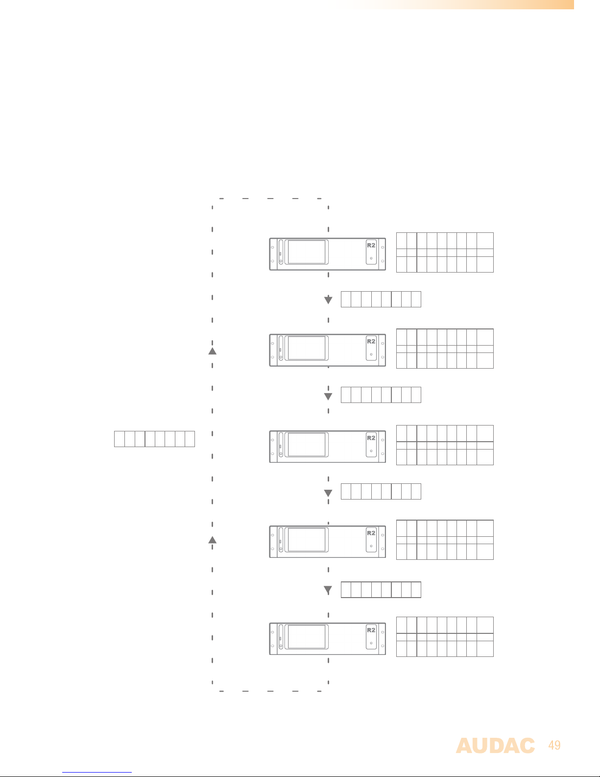
The diagram shown below shows an audio flow of an example project with 5 R2’s cascaded
through the fiber interconnection interface where every R2 has an address going from “R001”
to “R005”. Next to every R2 are shown which signals are received and transmitted over the
fiber, while next to the connection line is shown which signals the fiber is carrying at this point.
Paging
R005(1)
R005(2)
R001(1)
R003(1)
R004(1)
R005(4)
R005(3)
In
Fb 1 Fb 2 Fb 3 Fb 4 Fb 5 Fb 6 Fb 7 Fb 8 Channel
Paging
R005(1)
R005(1)
R001(1)
R003(1)
R004(1)
R001(2)
R005(3)
Out
R2
R2
R2
R2
R2
R001
R002
R003
R004
R005
Paging
R005(1)
R005(2)
R001(1)
R003(1)
R004(1)
R001(2)
R005(3)
In
Fb 1 Fb 2 Fb 3 Fb 4 Fb 5 Fb 6 Fb 7 Fb 8 Channel
Paging
R005(1)
R005(1)
R001(1)
R003(1)
R002(1)
R002(2)
R005(3)
Out
Paging
R005(1)
R005(2)
R001(1)
R003(1)
R002(1)
R002(2)
R005(3)
In
Fb 1 Fb 2 Fb 3 Fb 4 Fb 5 Fb 6 Fb 7 Fb 8 Channel
Paging
R005(1)
R005(1)
R001(1)
R003(1)
R002(1)
R003(2)
R005(3)
Out
Paging
R005(1)
R005(2)
R001(1)
R003(1)
R002(1)
R003(2)
R005(3)
In
Fb 1 Fb 2 Fb 3 Fb 4 Fb 5 Fb 6 Fb 7 Fb 8 Channel
Paging
R005(1)
R005(1)
R001(1)
R003(1)
R004(1)
R004(2)
R005(3)
Out
Paging
R005(1)
R005(2)
R001(1)
R003(1)
R004(1)
R004(2)
R005(3)
In
Fb 1 Fb 2 Fb 3 Fb 4 Fb 5 Fb 6 Fb 7 Fb 8 Channel
Paging
R005(1)
R005(1)
R001(1)
R003(1)
R004(1)
R005(4)
R005(3)
Out
Paging
R005(1)
R005(1)
R001(1)
R003(1)
R004(1)
R001(2)
R005(3)
Paging
R005(1)
R005(1)
R001(1)
R003(1)
R002(1)
R002(2)
R005(3)
Paging
R005(1)
R005(1)
R001(1)
R003(1)
R002(1)
R003(2)
R005(3)
Paging
R005(1)
R005(1)
R001(1)
R003(1)
R004(1)
R004(2)
R005(3)
Paging
R005(1)
R005(1)
R001(1)
R003(1)
R004(1)
R005(4)
R005(3)
Diagram
Fiber audio flow
Page 50

50
Diagram explanation
Every R2 is indicated with a different colour, and next to every R2 is a table shown with 8 incoming
fiber audio channels and 8 outgoing fiber audio channels. Between two devices, a connection
line is shown representing the fiber conductor, and next to this connection line is always a table
shown which indicates the audio channels the fiber conductor is carrying at this point. The
audio channels between the output from the previous device and the input of the next device
are always unchanged. This is clearly displayed by means of the text colour inside the tables.
When APM paging consoles are connected and paging over fiber enabled, then channel “Fb
1” is dedicated for paging use and can’t be used to exchange other audio channels. For this
reason, channel “Fb 1” is always marked with “Paging”.
An overview of the audio signals transmitted over the fiber interface:
- Fiber channel 1 (Fb 1): This channel is dedicated for paging purposes
- Fiber channel 2 (Fb 2): The Red R2 (R005) transmits an audio signal over fiber
channel “Fb 2”. This signal reaches all devices and can
be used by all devices.
- Fiber channel 3 (Fb 3): Same as channel “Fb 2”, the Red R2 (R005) transmits an
audio signal over fiber channel “Fb 3”. This signal
reaches all devices and can be used by all devices.
- Fiber channel 4 (Fb 4): The Yellow R2 (R001) transmits an audio signal over fiber
channel “Fb 4”. This signal reaches all devices and can
be used by all devices.
- Fiber channel 5 (Fb 5): The Blue R2 (R003) transmits an audio signal over fiber
channel “Fb 5”. This signal reaches all devices and can
be used by all devices.
- Fiber channel 6 (Fb 6): Channel 6 is used by two R2’s. The Orange R2 (R004)
transmits an audio signal over fiber channel 6 “Fb 6”, and
this signal reaches the Red R2 (R005), the Yellow R2
(R001) and the Green R2 (R002). The Green R2 (R002)
replaces the signal on fiber channel “Fb 6” by another
audio signal, and this audio signal reaches the Blue R2
(R003) and the Orange R2 (R004).
-Fiber channel 7 (Fb 7): Fiber channel 7 (Fb 7) is used by all R2’s. Every R2
receives and transmits an audio signal over this channel.
This way, every R2 can use a source of the previous R2
and replace it by another signal which can be received by
the next R2 in the ring network.
- Fiber channel 8 (Fb 8): Same as channels “Fb 2” and “Fb 3”, the Red R2 (R005)
transmits an audio signal over fiber channel “Fb 8”. This
signal reaches all devices and can be used by all devices.
Page 51
51
Setting up the project
This chapter describes a step by step setup procedure which teaches you how to
configure an R2 setup with multiple devices as shown on the previous pages.
NOTE
Don’t make any ethernet or fiber connections until this point. The setup should be configured
in the same sequence as described in this step by step guide.
1) Configuration of R2 Address
The first thing which should be done, is configuring the IP and bus addresses of all
devices used in your setup. When devices are cascaded through fiber, the control can be
done in two different ways:
Method 1:
Connect one device to Ethernet, and control the other devices in your setup through
the same IP address. The data will be transferred between the devices over the fiber
conductor. The advantage of this method is: Only one Ethernet connection is necessary.
The disadvantage of this method is: you can only see the VU meters in the user interface
of the R2 which is directly connected to the Ethernet network. (All other settings can me
made, except the VU meter bar graph which is only visible for the direct connected R2)
To configure your system according to Method 1, proceed with the following procedure:
1) Connect the first R2 of your setup to your Ethernet network
2) Set the address for the first R2 to “R001”, this can be done in the “Setup” menu,
under “R2 Address Settings”.
3) Disconnect the first R2 of your setup from the Ethernet network
4) Connect the second R2 of your setup to your Ethernet network
5) Set the address for the second R2 to “R002”, this can be done in the “Setup”
menu, under “R2 Address Settings”.
6) Disconnect the second R2 of your setup from the Ethernet network
7) Repeat this procedure for all R2’s in your setup, and assign an unique bus address
to every R2 in your setup.
8) After this is done, all R2’s should have an unique bus address, and no R2 is longer
connected to the Ethernet network.
9) Connect one of the R2’s in your setup to the Ethernet network. (It doesn’t matter
which one you connect to the Ethernet network, but mind you can only see the VU
meter bar graph moving of the connected R2)
10) Connect the R2’s with each other through fiber conductors, using the loop
principle as shown in Figure 1.
11) Restart all R2’s
12) All R2’s should display now “Fiber OK” on top of their main page, next to the
connection status.
Method 2:
Connect all devices to Ethernet, and control them by their own IP address. The advantage
of this method is: you can see the VU meters of all connected R2’s. The disadvantage of
this method is: every device needs his own Ethernet connection and IP address.
To configure your system according to Method 2, proceed with the following procedure:
Page 52
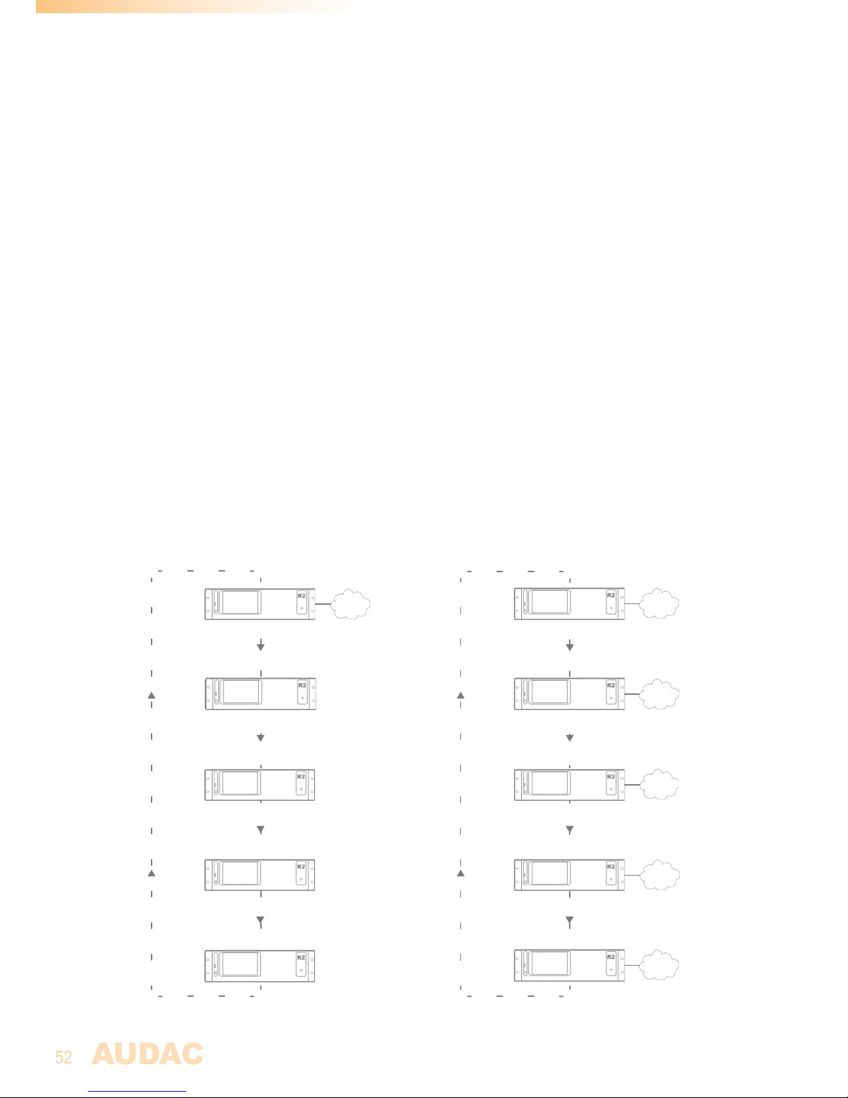
52
1) Connect the first R2 of your setup to your Ethernet network
2) Set the address for the first R2 to “R001”, this can be done in the “Setup” menu,
under “R2 Address Settings”.
3) Change the IP address for the first device to one which is available in your
ethernet network (For example 192.168.0.191). This can be done in the “Setup”
menu, under “Network Settings”.
4) Disconnect the first R2 of your setup from the Ethernet network
5) Connect the second R2 of your setup to your Ethernet network
6) Set the address for the second R2 to “R002”, this can be done in the “Setup”
menu, under “R2 Address Settings”.
7) Change the IP address for the second device to one which is available in your
ethernet network (For example 192.168.0.192). This can be done in the “Setup”
menu, under “Network Settings”. Make sure this IP address is different from the
first device’s IP address.
8) Disconnect the second R2 of your setup from the Ethernet network
9) Give all the R2’s in your setup an unique bus and IP address. This can be done by
repeating step 5 to 8 of this procedure. Make sure every device has an unique bus
and IP address.
10) Now, all devices have an unique bus and IP address, and no device is connected
to the Ethernet network.
11) Connect all devices to your ethernet network
12) Connect the R2’s with each other through fiber conductors, using the loop
principle as shown in Figure 1.
13) Restart all R2’s
14) All R2’s should display now “Fiber OK” on top of their main page, next to the
connection status.
Example setup with 5 R2’s, on the left side with only one Ethernet connection (Method 1) while on the right
side every R2 has a separate ethernet connection (Method 2)
R2
R2
R2
R2
R2
R001
R002
R003
R004
R005
R2
R2
R2
R2
R2
R001
R002
R003
R004
R005
Ethernet
192.168.0.191
Ethernet
192.168.0.191
Ethernet
192.168.0.192
Ethernet
192.168.0.193
Ethernet
192.168.0.194
Ethernet
192.168.0.194
Page 53
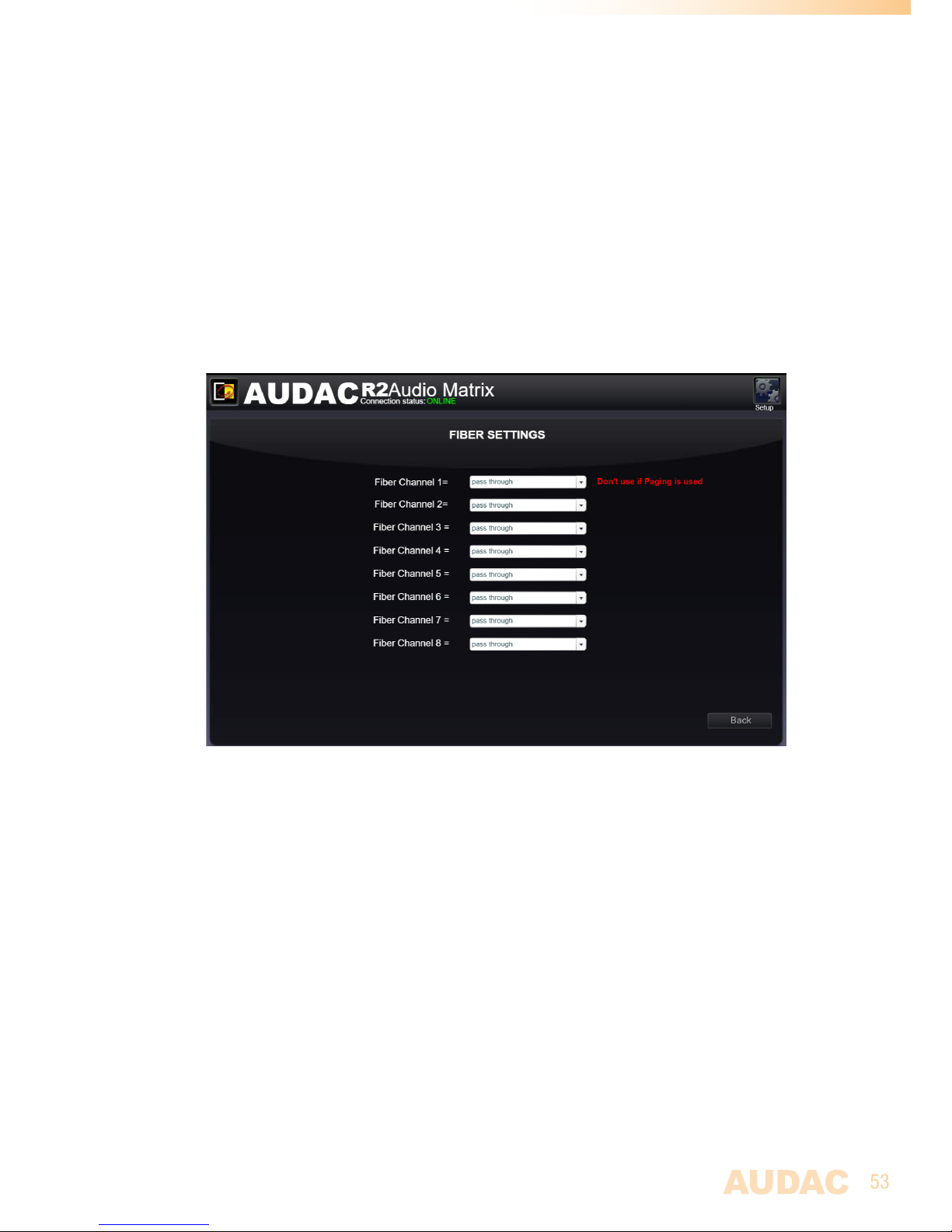
53
2) Configuration of Fiber channels
The next step is the configuration of the audio channels transmitted over the fiber
conductor. This can be done in the “Setup” menu, under “Fiber settings”. Below, we’ll give
a step by step guide about the fiber configuration for one device in your setup. Let’s start
with the first R2 with address “R001” (indicated in Yellow) in your setup.
1) Open the user interface of the selected R2 “R001”.
2) Open the “Settings” menu and click the “Fiber Settings” button.
3) As shown in figure 1, “R001” transmits audio signals over fiber channel “Fb 4”
and “Fb 7”. For all the other fiber channels, “R001” just send the incoming data
to the next R2. So a source signal should be selected for fiber channels “Fb 4”
and “Fb 7”. All signals available on the R2 can be selected by means of the
dropdown list. For all other channels where the incoming data is just send to the
next R2, status “off” should be selected in the dropdown list.
4) Repeat this procedure for all R2’s in your setup
5) After this is done, all selected audio signals are transmitted over the fiber
conductor, and can be
used by other R2’s in your setup.
3) Set passwords
You can skip this step if the default password “R2” for administrator and “user” for users
is OK for you, but we always recommend to change the passwords. A detailed description
how the passwords can be changed can be found inside an earlier chapter of this user
manual. It’s convenient to give all the R2’s in your setup the same administrator password,
making it possible to swap between R2’s without constantly reentering the password. At
user level, it’s always necessary to reenter the password after swapping between R2’s.
4) Connecting sources
Connect all your audio sources (CD-players, Tuners, ... ) to the line inputs on the back of
the R2. Adjust all input gains so there is no clipping. More information about connecting
source is extensively described in an earlier chapter of this user manual.
Page 54

54
5) Connecting wallpanels
Connect all your wallpanels to the Peripheral inputs on the rear of the R2. A detailed
description about connecting wallpanels is extensively described in an earlier chapter of
this user manual.
6) Ready
Your project is now ready for use.
Page 55

55
Chapter 8
Additional information
IP Basics
Many AUDAC products are controllable by Ethernet. The Ethernet connection which is used
on the AUDAC products is Transmission Control Protocol (TCP) & the Internet Protocol (IP)
(TCP/IP) based. There are some basics which you need to know to successfully make a TCP/
IP Ethernet connection.
Nearly all computers today support TCP/IP. TCP/IP is not a single networking protocol – it is
a suite of protocols named after the two most important protocols or layers within it – TCP
an d I P.
As with any form of communication, two things are needed: a message to transmit and
the means to reliably transmit the message. The TCP layer handles the message part. The
message is broken down into smaller units, called packets, which are then transmitted over
the network. The packets are received by the corresponding TCP layer in the receiver and
reassembled into the original message.
The IP layer is primarily concerned with the transmission portion. This is done by means of
a unique IP address assigned to each and every active recipient on the network.
TCP/IP is considered a stateless protocol suite because each client connection is newly made
without regard to whether a previous connection had been established.
The IP address is always a number in the following format “192.168.000.001”. As you can
see, this address consists of 4 separate numbers ranging from “000” to “255”.
In simple terms, only the latest number of an IP address can be different within a network,
so there is a maximum of 256 unique addresses within a network, ranging from “xxx.
xxx.xxx.000” to “xxx.xxx.xxx.255”. The first three numbers must be the same to make
communication between several devices possible, else the devices can not communicate
with each other.
Example:
Device 1: IP address: 192.168.000.001
Device 2: IP address: 192.168.000.002
Device 3: IP address: 192.168.001.003
In this example, Device 1 can communicate with Device 2, but not with Device 3, because
the first three numbers must be the same. These first three parts are called the “IP
range”, so the devices must be in the same “IP range” to communicate with each other.
The “IP range” of home and office networks are defined by the network administrator,
this means that the IP range of your home or office network can be different from another
network. AUDAC products have the following IP address as default: “192.168.0.xxx”, this
means the standard IP range of AUDAC products is “192.168.000.xxx”. If your network is
using a different IP range, the AUDAC products will not be accessible from your network.
You can change the IP address of the AUDAC products to make them work properly in
Page 56
56
your network. This can be done in the settings menu, and is described extensively in the
“Settings” chapter of this user manual.
Of course, to make changes to the settings menu of the AUDAC products, you must have
access to the user interface on the products webpage. This can be done by temporarily
giving your computer an IP address within the IP range of the AUDAC product, for
example “192.168.0.200”. After the IP address of your computer is within the IP range
of the product, the user interface is accessible and the IP address of the product can be
changed to an IP address within the IP range of your network. If the IP address of the
product is within the IP range of your network, you can change the IP address of your
computer again to it’s former IP address and the product should work properly in your
home or office network.
Ask your network administrator for help if you are not familiar with networks.
Summary
- All devices must have an unique IP address
- All devices must be within the same IP range
Updating the R2
New features and improvements will be continuously added to the R2’s software.
It is therefor recommended to always keep your R2 running on the latest software version
to have optimal performance and most reliable experience under all circumstances.
For more information about the latest available updates and the step by step procedure
how this software update should be performed, please check our website.
The easiest way to keep your R2 device up to date is through the Audac System Manager.
The Audac System manager (ASM) is a windows compatible software application which
detects all ‘smart’ devices with their peripherals in your system and allows extended
configuration, update and backup functions for the equipment.
It will automatically detect and download the latest firmware updates from the AUDAC
server.
For more information regarding the Audac system manager, please visit our website @
www.AUDAC.eu.
Page 57

57
Technical specifications
Inputs Unbalanced Stereo Type 8 x Stereo Unbalanced Line
Connector RCA
Frequency range 20 Hz - 20 kHz
Sensitivity - 50 dBV ~ +10 dBV
THD + N 0.01 %
Signal / Noise < 110 dB
Impedance 10 k Ohm
Priority Audio 2 x Mono Balanced Line / Mic (3-pin Euro Terminal Block ~ 5.08 mm)
Frequency range 20 Hz - 20 kHz
Sensitivity - 50 dBV ~ +10 dBV
THD + N 0.02 %
Signal / Noise < 110 dB
Impedance 600 Ohm
Priority Contact 2 x Priority Contact Input (2-pin Euro Terminal Block ~ 5.08 mm)
Peripheral Interface 8 x Digital audio / RS485 / 24 V DC (RJ45)
2 x RS485 + 24 V DC (RJ45)
Remote Control Ethernet 10Mb (RJ45 )
RS-232 (D-Sub 9)
Power: Mains power IEC Type C13 with fuse
Emergency power 2-pin Euro Terminal Block ~ 5.08 mm
Outputs Unbalanced Stereo Type 8 x Stereo Unbalanced Line
Connector RCA
Control possibilities RS232
Wall Panels (RS485)
Smart devices (Audac Touch)
TCP/IP (Integrated webserver)
Front panel (Optional touchscreen)
Power supply Mains power 100 ~ 240 V AC / 50 ~ 60 Hz
Emergency power 24VDC +/- 20%
Power consumption R2 20W
R2DIS 4W
POW2 idle: 41W
1/8 rated power: 200W
1/3 rated power: 400W
OPT2 0.3W
Weight 8.85 Kg
Dimensions (W x H x D) 482 x 132 x 335 mm
Unit height 3HE
Page 58
58
Notes
Page 59
59
Notes
Page 60
60
Notes
 Loading...