

Page 1

PRE220/240
User Manual
www.audac.eu
Page 2

2
ADDITIONAL INFORMATION
This manual is put together with much care, and is as complete as could be on the
publication date. However, updates on the specifications, functionality or software may
have occurred since publication. To obtain the latest version of both manual and software,
please visit the Audac website @ www.audac.eu.
Page 3

3
Index
Introduction 5
Precautions 6
Safety requirements 6
Caution servicing 6
EC Declaration of Conformity 6
Waste of Electrical and Electronic Equipment (WEEE) 7
Caution 7
Chapter 1: Pin connections and connectors 9
Connection standards 9
Chapter 2: Front & rear panel 10
Front panel overview 10
Front panel description 10
Rear panel overview 11
Rear panel description 11
Enabling phantom power & talkover 12
Chapter 3: Additional information 13
Technical specifications 13
Notes 15
Page 4

4
Page 5

5
Introduction
10-Channel stereo preamplifiers
The PRE2xx series preamplifiers are solutions for applications where a large number (up to
8) of microphones (or other mono balanced audio inputs) need to be mixed to two output
zones. The multifunctional stereo design with a total of 10 inputs allows connection for any
type of audio source such as microphones, Bluetooth devices or line level audio sources.
Channels one to eight are balanced inputs, allowing the connection of microphones or line
level audio sources with the ability of enabling 48V phantom power to each input. They
feature 3-band tone control and talk-over for priority announcements. The other two (9
and 10) inputs are unbalanced stereo line inputs allowing connection of any type of line level
audio source.
An integrated Bluetooth receiver and a front panel 3.5 mm jack offer convenient wired
or wireless connection possibilities for mobile and portable devices including laptops,
smartphones and tablets. The front panel includes a master volume control with 2-band
tone control and LED VU bar for each output.
Each input section is accommodated with input mixing dials and output selection switches.
A priority mute for each zone output suppresses all (non-priority) music sources in case of
contact closure, allowing linking autonomous alarm systems.
Page 6

6
Precautions
READ FOLLOWING INSTRUCTIONS FOR YOUR OWN SAFETY
ALWAYS KEEP THESE INSTRUCTIONS. NEVER THROW THEM AWAY
ALWAYS HANDLE THIS UNIT WITH CARE
HEED ALL WARNINGS
FOLLOW ALL INSTRUCTIONS
NEVER EXPOSE THIS EQUIPMENT TO RAIN, MOISTURE, ANY DRIPPING OR SPLASHING
LIQUID. AND NEVER PLACE AN OBJECT FILLED WITH LIQUID ON TOP OF THIS DEVICE.
DO NOT PLACE THIS UNIT IN AN ENCLOSED ENVIRONMENT SUCH AS A BOOKSHELF
OR CLOSET. ENSURE THERE IS ADEQUATE VENTILATION TO COOL THE UNIT. DO NOT
BLOCK THE VENTILATION OPENINGS.
DO NOT STICK ANY OBJECTS THROUGH THE VENTILATION OPENINGS.
DO NOT INSTALL THIS UNIT NEAR ANY HEAT SOURCES SUCH AS RADIATORS OR
OTHER APPARATUS THAT PRODUCE HEAT
DO NOT PLACE THIS UNIT IN ENVIRONMENTS WHICH CONTAIN HIGH LEVELS OF DUST,
HEAT, MOISTURE OR VIBRATION
THIS UNIT IS DEVELOPED FOR INDOOR USE ONLY. DO NOT USE IT OUTDOORS
PLACE THE UNIT ON A STABLE BASE OR MOUNT IT IN A STABLE RACK
ONLY USE ATTACHMENTS & ACCESSORIES SPECIFIED BY THE MANUFACTURER
UNPLUG THIS APPARATUS DURING LIGHTNING STORMS OR WHEN UNUSED FOR LONG
PERIODS OF TIME
ONLY CONNECT THIS UNIT TO A MAINS SOCKET OUTLET WITH PROTECTIVE
EARTHING CONNECTION
THE MAINS PLUG OR APPLIANCE COUPLER IS USED AS THE DISCONNECT DEVICE, SO
THE DISCONNECT DEVICE SHALL BE READILY OPERABLE
THIS DEVICE IS NOT SUITABLE FOR USE IN LOCATIONS WHERE CHILDREN ARE LIKELY
TO BE PRESENT
Page 7
7
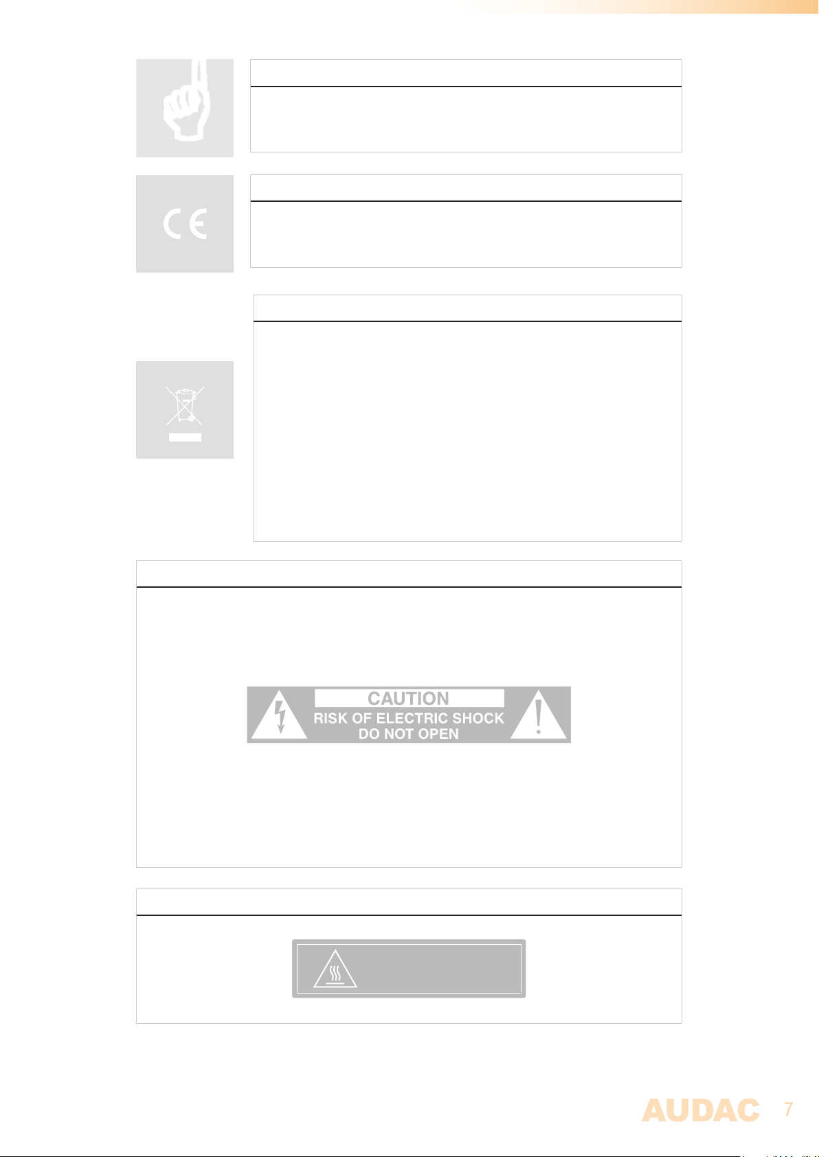
CAUTION - SERVICING
This product contains no user serviceable parts. Refer all servicing to
qualified service personnel. Do not perform any servicing (unless you
are qualified to)
EC DECLARATION OF CONFORMITY
This product conforms to all the essential requirements and further
relevant specifications described in following directives: 2014/30/EU
(EMC) and 2014/35/EU (LVD)
WASTE ELECTRICAL AND ELECTRONIC EQUIPMENT (WEEE)
The WEEE marking indicates that this product should not be disposed
with regular household waste at the end of its life cycle. This regulation
is created to prevent any possible harm to the environment or human
health.
This product is developed and manufactured with high quality materials
and components which can be recycled and/or reused. Please
dispose this product at your local collection point or recycling centre
for electrical and electronic waste. This will make sure that it will be
recycled on an environmentally friendly manner, and will help to protect
the environment in which we all live.
CAUTION
The symbols shown are internationally recognized symbols that warn about potential
hazards of electrical products. The lightning flash with arrow point in an equilateral triangle
means that the unit contains dangerous voltages. The exclamation point in an equilateral
triangle indicates that it is necessary for the user to refer to the users manual.
These symbols warn that there are no user serviceable parts inside the unit. Do not open the
unit. Do not attempt to service the unit yourself. Refer all servicing to qualified personnel.
Opening the chassis for any reason will void the manufacturer’s warranty. Do not get the
unit wet. If liquid is spilled on the unit, shut it off immediately and take it to a dealer for
service. Disconnect the unit during storms to prevent damage.
CAUTION HOT SURFACE
CAUTION: Hot surface
Do not touch
Page 8

8
POWER SUPPLY AND POWER CORD REQUIREMENTS
Power supply class I grounding requirements:
For protection from fault currents, the equipment shall be connected to a grounding terminal.
Plug the system power cord into an AC outlet that provides a ground connection. Substitute
cords may not provide adequate fault protection. Only use the power cord supplied with
this product or an authorized/equivalent replacement
Safety notices:
Denmark:
Apparatets stikprop skal tilsluttes en stikkontakt med jord, som giver forbindelse
til stikproppens jord.
Finland:
Laite on liitettävä suojakoskettimilla varustettuun pistorasiaan.
Norway:
Apparatet må tilkoples jordet stikkontakt.
Sweden:
Apparaten skall anslutas till jordat uttag.
ATTENTION
The fuse (T500mAL/250V) provides a safeguard function to the device. When replacing
the fuse, make sure that the value of the replacement matches the value of the original
fuse. Identification of a suitable replacement component or substitute shall be done by
qualified technicians.
Page 9
9
Chapter 1
Pin connections and connectors
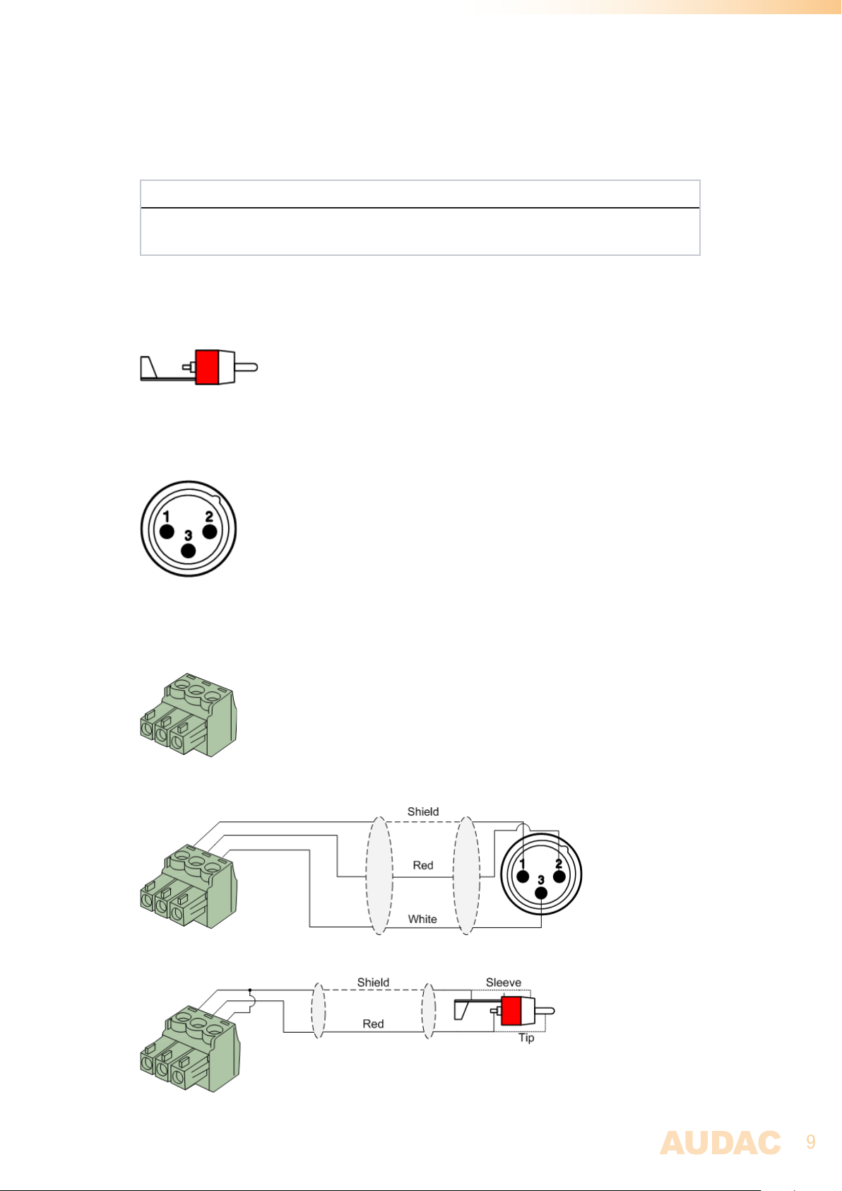
CONNECTION STANDARDS
The in- and output connections for AUDAC audio equipment are performed corresponding
to international wiring standards for professional audio equipment.
Cinch (RCA):
For unbalanced line input connections
Tip: Signal Sleeve: Ground
White: Left Red: Right
XLR:
For balanced signal input connections
Pin 1: Ground
Pin 2: Signal +
Pin 3: Signal -
3-Pin Terminal Block:
For balanced signal input & link output connections.
Left: Signal - (XLR Pin 3)
Center: Signal + (XLR Pin 2)
Right: Ground (XLR Pin 1)
For balanced line output connections:
For unbalanced line output connections:
Page 10
10
Chapter 2
Front & rear panel
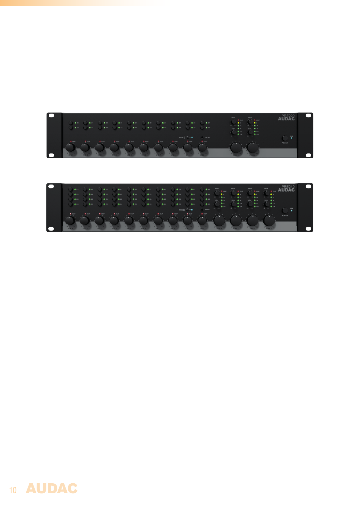
Front panel overview
Front panel description
Input mixing controls:
Using the input mixing controls, the individual level for each input can be adjusted. Each
input control is provided with a clip indicator LED which illuminates when the maximum level
(clipping) is almost reached. To ensure the best signal-to-noise ratio, illumination of this
indicator should only occur at peak levels. When it illuminates frequently, the channel will
be overdriven and a distorted ‘clipping’ sound will occur.
Signal routing selection buttons:
The signal routing buttons located on the right side of each input mixing control (indicated
with ‘Z1’ and ‘Z2’ for PRE220 and ‘Z1 to Z4’ for PRE240) are used for selection for routing
each input to one or both output channels. Press this button to enable the input routing to
the corresponding output. The corresponding routing indicator LED illuminates when routed.
Bluetooth (CH1):
The integrated Bluetooth receiver is mixed with channel 1 and contains a pairing button
besides the input mixing control. This allows connection of the pre-amplifier with any
supporting audio source device such as smartphone or tablet. The LED positioned beside
this button indicates the current operation mode. When non illuminating, the device cannot
be discovered by (new) Bluetooth devices. When blinking, the device is not connected but can
be discovered through Bluetooth devices, and when illuminated it is connected and doesn’t
allow pairing with another device.
Page 11
11
When pairing with your device for the first time, the ‘PAIR’ button should be pressed and the
LED will start blinking for about 2 minutes. During this period, the device can be discovered
and is indicated as Bluetooth ID ‘AUDAC PRE series xxxx’ (where the xxxx stands for an
unique ID for each single device). When both devices have been paired before, the transmitter
will be recognized by the receiver and will allow continuous pairing without pressing the
‘PAIR’ button.
3.5 mm Jack input (CH2):
A 3.5 mm jack input connection is provided on the front panel of the unit on top of the channel
2 mixing control. This input is an unbalanced stereo line input, mixed with the rear panel
input of channel 2. Any portable device (such as laptop, smartphone or tablet) with 3.5 mm
jack audio output can be connected to this easy accessible input.
NOTE
The gain control potentiometers for channel 1 (mixed with Bluetooth receiver) and channel 2
(mixed with front 3.5 mm jack input) are also affecting the level for these secondary inputs.
Output master control:
Each output section contains a master volume control, two band tone control and 6-segment
VU LED bar. The master volume control allows regulation of the overall output level, while
two-band tone control allows bass / treble adjustment within a range of ± 15 dB and the
VU LED bar indicates the overall output level.
Power switch:
Allows to power the system ON and OFF. The blue indicator LED illuminates when switched on.
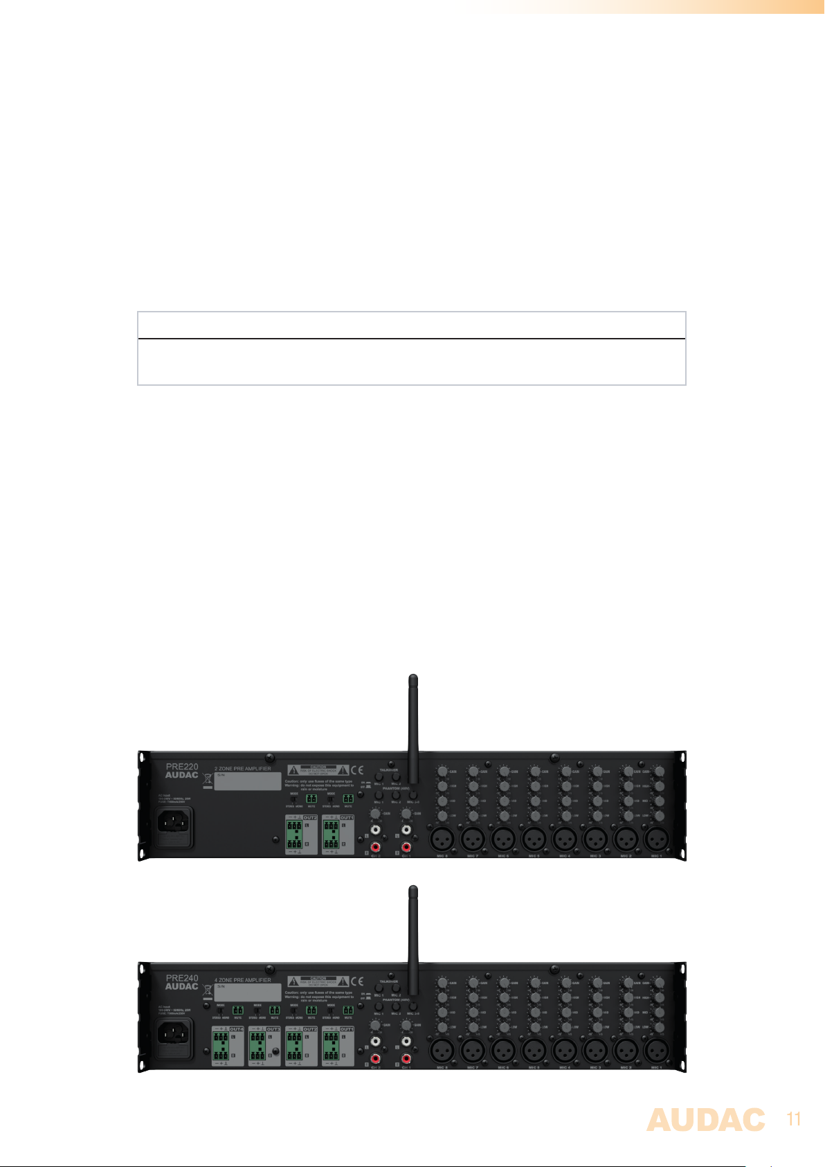
Rear panel overview
Page 12

12
Rear panel description
AC Power inlet with fuse:
The mains power supply (100-240V AC - 50/60 Hz) has to be applied to this AC power
inlet. The connection is made by an IEC C14 power connector and is fitted with a fuse. When
replacing the fuse, make sure that the value of the replacement fuse matches the value of
the original fuse. (T500mAL/250V)
Balanced stereo line output:
The balanced stereo line outputs are implemented using two 3-pin terminal block output
connectors. The audio signal available on these connectors allows it to be fed to any amplifier.
A mode switch allows to convert the output between stereo and mono. In mono mode, a
summed mono signal will be available on both left & right outputs, allowing the signal be
fed to mono systems such as 100V PA systems.
Priority mute contact:
A priority mute contact is provided with each output, allowing to completely mute the music
at presence of a contact closure between both terminals. This contact is convenient for
situations where a separate emergency system is installed and complete background music
muting is required at occasion of a (fire) alarm. The emergency system contact outputs can
be connected to this contact input.
Bluetooth antenna connection:
The included Bluetooth antenna should be connected to this terminal for good signal reception.
It is connected using an SMA type connector and allows antenna extension (with an optional
extension cable) for mounting outside of closed rack cabinets.
Unbalanced stereo line inputs:
Unbalanced line level input sources (e.g. media-players, radio tuners, ...) can be connected
to line inputs channel 1 and channel 2. These standard line inputs are implemented using
RCA connectors and fitted with a gain control potentiometer whereby the input sensitivity
can be controlled within a range of +4 dB ~ -20 dB.
Balanced microphone inputs:
Balanced mono sources (e.g. microphones) can be connected to inputs mic 1 to mic 8 which
are implemented using XLR connectors. They are fitted with a gain control potentiometer
whereby the sensitivity can be adjusted within a range of -6 dB ~ -50 dB.
These inputs are fitted with a three-band tone control, allowing signal equalization within
a range of ± 15 dB.
Page 13
13
Enabling phantom power & talkover
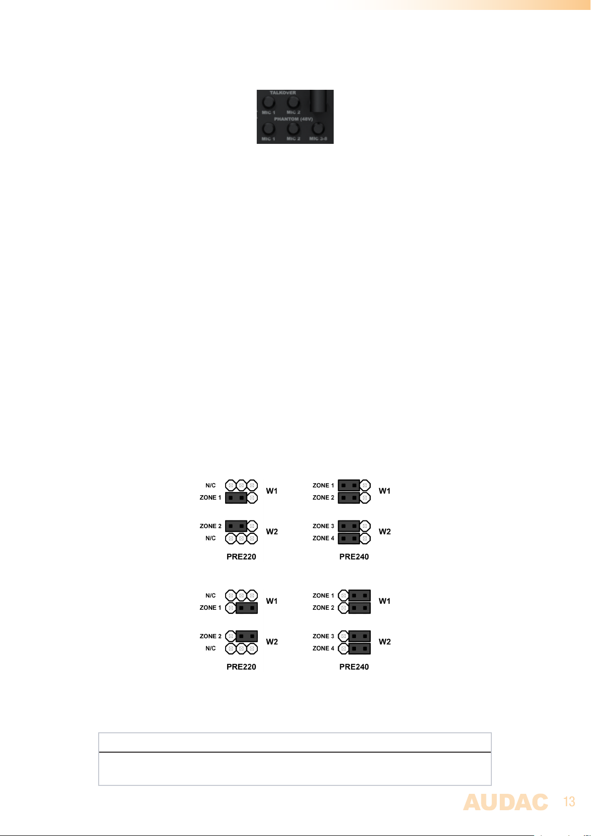
Phantom power:
The phantom power switches on the rear side of the pre-amplifier enable phantom power
(48V) to the inputs for powering condenser microphones. The first switch ‘MIC 1’ enables
phantom power to the first input, the second switch ‘MIC 2’ enables phantom power to the
second input while switch ‘Mic 3-8’ enables phantom power to all other microphone inputs.
Make sure the connected devices are supporting phantom power before enabled, to avoid
damage to the connected equipment.
Talkover (Mic 1/2):
When talkover switches for ‘Mic 1’ and/or ‘Mic 2’ are enabled, it suppresses all other audio
sources in case of presence of a signal on these inputs. All other audio signals are suppressed
with -24 dB. This function is useful when used in combination with priority audio sources
which shall be heard clearly under all circumstances (e.g. priority microphones, voice
announcement systems, alarm systems, ... ).
Talkover (Mic 3-8):
When talkover for more than two inputs is required, this can be enabled for microphone
inputs 3 to 8 through jumpers located internally in the device (on the front PCB board). For
enabling this, the top cover of the device shall be removed and the jumper settings shall be
made as shown in the below diagram.
The talkover is enabled when the jumpers are placed in the left position, while the talkover
is disabled when the jumpers are in the right position.
Jumper settings for enabled talkover
Jumper settings for disabled talkover
Jumpers with positions ‘W1’ and ‘W2’ are affecting input 3, while higher numbers are related
with higher input numbers.
ATTENTION
Because these jumper settings require the housing from the electronic device to be opened,
these settings are allowed to be made by qualified technicians only.
Page 14

14
Chapter 3
Additional information
Technical specifications
Inputs Mic 1 to 8 Type Balanced microphone
Connector Female XLR
Sensitivity -6 dB ~ -50 dB
Other 3-Band tone control
Phantom power (48V DC)
Talkover
Channel 1 & 2 Type Unbalanced stereo line
Connector Female RCA (2x)
Sensitivity +4 dB ~ -20 dB
Bluetooth Type Integrated Bluetooth receiver
Mixed with Channel 1
Connector Male SMA connector
Other Included antenna
Front line input Type Unbalanced stereo line
Mixed with Channel 2
Connector 3.5 mm stereo jack
Priority mute contact Type Priority mute
2-pin terminal block ~ 3.81 mm
Outputs Type Balanced stereo line
(2 x for PRE220 - 4 x for PRE240)
Connector 3-pin terminal block ~ 3.81 pitch
Frequency response 20 Hz - 20 kHz
Signal to Noise ratio > 90 dB
Total Harmonic Distortion + Noise < 0.05%
Crosstalk > 70 dB
Controls Front panel control
Bluetooth receiver Bluetooth spec V4.1
Class 2 output power
Indicators Power
Clip (input & output)
Output VU
Power supply Type Switching mode
Range 100-240V~, 50/60 Hz
Power consumption 26 Watt
Page 15

15
Dimensions (W x H x D) 482 x 88 x 330 mm
Unit height 2 HE
Weight PRE220 4.45 Kg
PRE240 4.50 Kg
Page 16

16
Notes
 Loading...