

Page 1
NOBA8A
User Manual
www.audac.eu
Page 2

2
ADDITIONAL INFORMATION
This manual is put together with much care, and is as complete as could be on the
publication date. However, updates on the specifications, functionality or software may
have occurred since publication. To obtain the latest instruction manual or obtain additional
product information, please visit the product page on www.audac.eu. For information about
software version updates, please visit www.audac.eu/software.
Page 3

3
Index
Introduction 5
Precautions 5
Safety requirements 6
Caution servicing 6
EC Declaration of Conformity 6
Waste of Electrical and Electronic Equipment (WEEE) 7
Caution 7
Chapter 1: Pin connections and connectors 9
Connection standards 9
Wire up the system 9
Chapter 2: Front & rear panel 10
Control panel overview 10
Control panel description 10
Connection panel overview 11
Connection panel description 11
RMT40 remote control overview 12
RMT40 remote control connection 12
Chapter 3: Connecting the NOBA8A 13
Chapter 4: Loading presets & firmware updates 14
Chapter 5: Mounting the NOBA8A 15
Chapter 6: Additional information 17
Technical specifications 17
Notes 18
Page 4

4
Page 5

5
Introduction
8” Compact bass cabinet
NOBA8A is characterized by an innovative & unique design. With its curved shape, made of
4 mm thick aircraft graded aluminum and its extremely powerful 8” woofer of 200 Watts,
the NOBA8A is able to deliver an unheard low frequency response for its small woofer size.
The perfect acoustic experience is guaranteed when the entire audio frequency spectrum is
equally distributed. The slick look of the NOBA8A allows it to be placed against a wall, on the
ceiling or even underneath furniture, yet due to the unique composition of its parts, NOBAA
ensures a much better spreading of sound waves than other similar cabinets. NOBA8A’s
integrated class-D amplifier provides an impressive clarity of 150 Watts for both of the top
speaker outputs to ensure impeccable sound division.
It uses AUDAC’s WaveDynamics™ technology, which allows the user to easily set up the
optimal acoustic configuration. The user can simply load its preferred audio settings through
NOBA8A’s integrated USB input.
Page 6

6
Precautions
READ FOLLOWING INSTRUCTIONS FOR YOUR OWN SAFETY
ALWAYS KEEP THESE INSTRUCTIONS. NEVER THROW THEM AWAY
ALWAYS HANDLE THIS UNIT WITH CARE
HEED ALL WARNINGS
FOLLOW ALL INSTRUCTIONS
NEVER EXPOSE THIS EQUIPMENT TO RAIN, MOISTURE, ANY DRIPPING OR SPLASHING
LIQUID. AND NEVER PLACE AN OBJECT FILLED WITH LIQUID ON TOP OF THIS DEVICE
NO NAKED FLAME SOURCES, SUCH AS LIGHTED CANDLES, SHOULD BE PLACED ON
THE APPARATUS
DO NOT PLACE THIS UNIT IN AN ENCLOSED ENVIRONMENT SUCH AS A BOOKSHELF
OR CLOSET. ENSURE THERE IS ADEQUATE VENTILATION TO COOL THE UNIT. DO NOT
BLOCK THE VENTILATION OPENINGS.
DO NOT STICK ANY OBJECTS THROUGH THE VENTILATION OPENINGS.
DO NOT INSTALL THIS UNIT NEAR ANY HEAT SOURCES SUCH AS RADIATORS OR
OTHER APPARATUS THAT PRODUCE HEAT
DO NOT PLACE THIS UNIT IN ENVIRONMENTS WHICH CONTAIN HIGH LEVELS OF DUST,
HEAT, MOISTURE OR VIBRATION
THIS UNIT IS DEVELOPED FOR INDOOR USE ONLY. DO NOT USE IT OUTDOORS
PLACE THE UNIT ON A STABLE BASE OR MOUNT IT IN A STABLE RACK
ONLY USE ATTACHMENTS & ACCESSORIES SPECIFIED BY THE MANUFACTURER
UNPLUG THIS APPARATUS DURING LIGHTNING STORMS OR WHEN UNUSED FOR LONG
PERIODS OF TIME
ONLY CONNECT THIS UNIT TO A MAINS SOCKET OUTLET WITH PROTECTIVE
EARTHING CONNECTION
THE MAINS PLUG OR APPLIANCE COUPLER IS USED AS THE DISCONNECT DEVICE, SO
THE DISCONNECT DEVICE SHALL BE READILY OPERABLE
USE THE APPARATUS ONLY IN MODERATE CLIMATES
Page 7
7
EC DECLARATION OF CONFORMITY
This product conforms to all the essential requirements and further
relevant specifications described in following directives: 2014/30/EU
(EMC) and 2014/35/EU (LVD)
CAUTION - SERVICING
This product contains no user serviceable parts. Refer all servicing to
qualified service personnel. Do not perform any servicing (unless you
are qualified to)
CAUTION
The symbols shown are internationally recognized symbols that warn about potentional
hazards of electrical products. The lightning flash with arrowpoint in an equilateral
triangle means that the unit contains dangerous voltages. The exclamation point in
an equilateral triangle indicates that it is necessary for the user to refer to the users
manual.
These symbols warn that there are no user serviceable parts inside the unit. Do not
open the unit. Do not attempt to service the unit yourself. Refer all servicing to qualified
personnel. Opening the chassis for any reason will void the manufacturer’s warranty. Do
not get the unit wet. If liquid is spilled on the unit, shut it off immediately and take it to a
dealer for service. Disconnect the unit during storms to prevent damage.
WASTE ELECTRICAL AND ELECTRONIC EQUIPMENT (WEEE)
The WEEE marking indicates that this product should not be disposed
with regular household waste at the end of its life cycle. This regulation
is created to prevent any possible harm to the environment or human
health.
This product is developed and manufactured with high quality materials
and components which can be recycled and/or reused. Please
dispose this product at your local collection point or recycling centre
for electrical and electronic waste. This will make sure that it will be
recycled on an environmentally friendly manner, and will help to protect
the environment in which we all live.
Page 8

8
Page 9
9
Chapter 1
Pin connections and connectors
CONNECTION STANDARDS
The in- and output connections for AUDAC audio equipment are performed corresponding
to international wiring standards for professional audio equipment.
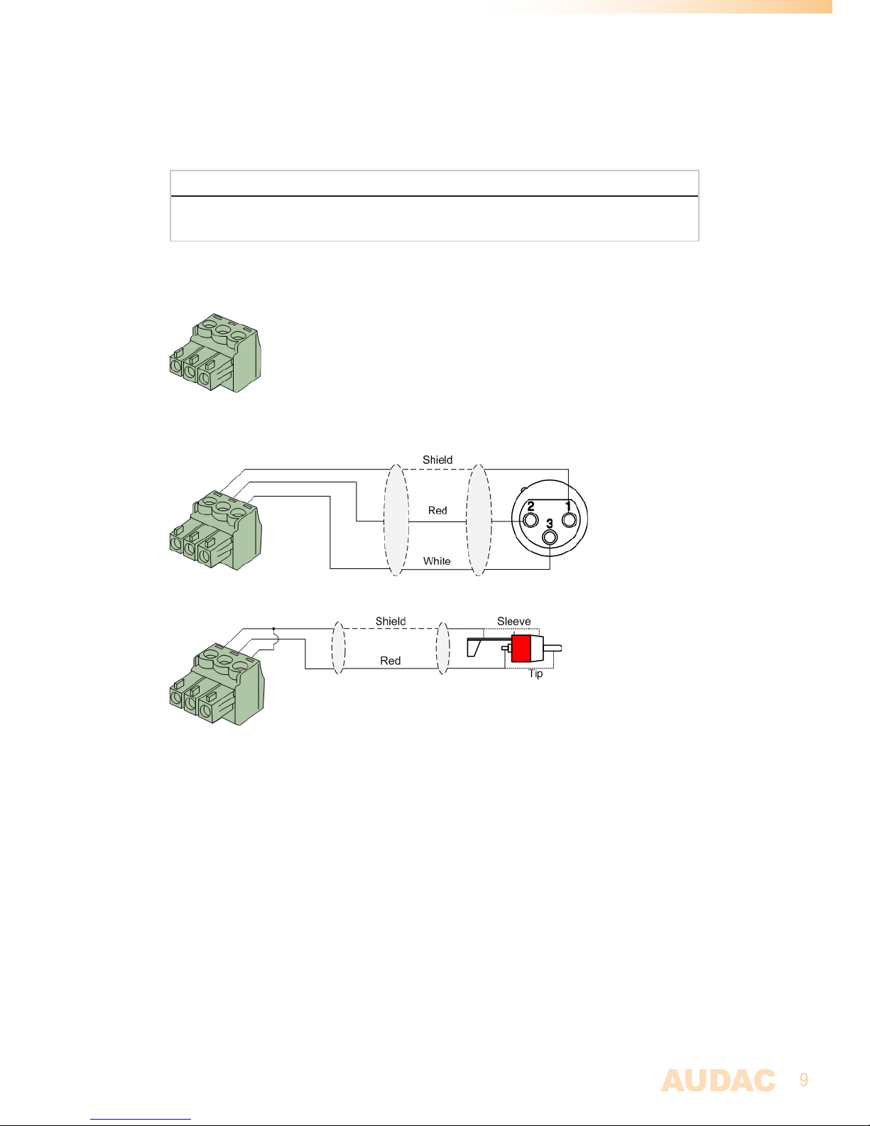
3-Pin Terminal Block:
For balanced signal input & link output connections.
Left: Signal - (XLR Pin 3)
Center: Signal + (XLR Pin 2)
Right: Ground (XLR Pin 1)
For balanced line input connections
:
For unbalanced line input connections:
Wire up the system
The wiring of the system must be done according to the following rules, to guarantee a
proper functioning of the system in all circumstances.
1. Speaker cable for amplified outputs:
Minimum 2 x 1.5 mm²
If distance > 15m: 2 x 2.5 mm²)
2. Audio signal inputs inputs (& signal linkthrough outputs)
Must be connected with high-quality audio cable and high-quality
connectors
Page 10
10
Chapter 2
NOBA8A overview
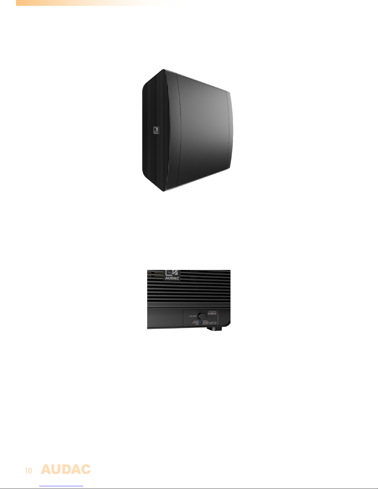
The aluminum enclosure features a grill on both sides. One side includes the amplifier, while
the bass port is located on the opposite side. To guarantee an optimal heat dissipation and
ventilation for the amplifier and to allow air-circulation through the bass port, make sure
that both sides remain uncovered when installed.
Control panel overview
Control panel description
Volume dial:
A volume dial located in the supporting structure of the bass cabinet (on the amplifier side)
allows adjustment of the input gain, regulating the overall system volume.
Indicator LED:
An multi color indicator LED gives an overview of the current operation status of the amplifier:
- Orange illuminated: Amplifier in standby mode
- Green illuminated: Input signal detected and amplifier operational
- Orange blinking: Input signal clipping
- Red blinking: Output signal clipping
Page 11
11
Standby mode:
A standby mode switches the NOBA8A to energy saving mode when no input signal is
detected for a certain period. The standby time is default configured to an interval of 5
minutes and can be adjusted or disabled by software configuration / preset loading.
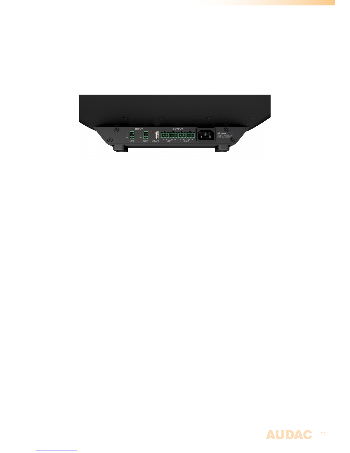
Connection panel overview
Connection panel description
Balanced stereo line input:
The signal input connections are balanced stereo line inputs implemented using two 3-pin
terminal block connectors. The line level audio signal coming from the audio source or preamplifier shall be fed to these input connections.
USB (Update) connection:
The USB (Update) connection is used for loudspeaker preset loading, system firmware updates
and/or for connection of the optional RF remote control (RMT40) receiver. For a detailed
description about speaker preset loading and firmware updates, check chapter 4 of this
instruction manual.
The provided LED indicates activity of the USB data transfer. Do not disconnect any USB
devices when this LED is illuminated.
Loudspeaker output (satellite) connections:
The satellite loudspeaker outputs are connected using four (two for each channel) 2-pin
terminal block connections. Both connections for each channel are identical, allowing easy
parallel linking for multiple speakers. The minimum connected load to each channel (both
output connections combined) shall be 4Ω.
AC Power inlet:
The mains power supply (100-240V AC - 50/60 Hz) has to be applied to this AC power inlet.
The connection is made through an IEC C14 power connector.
Page 12
12
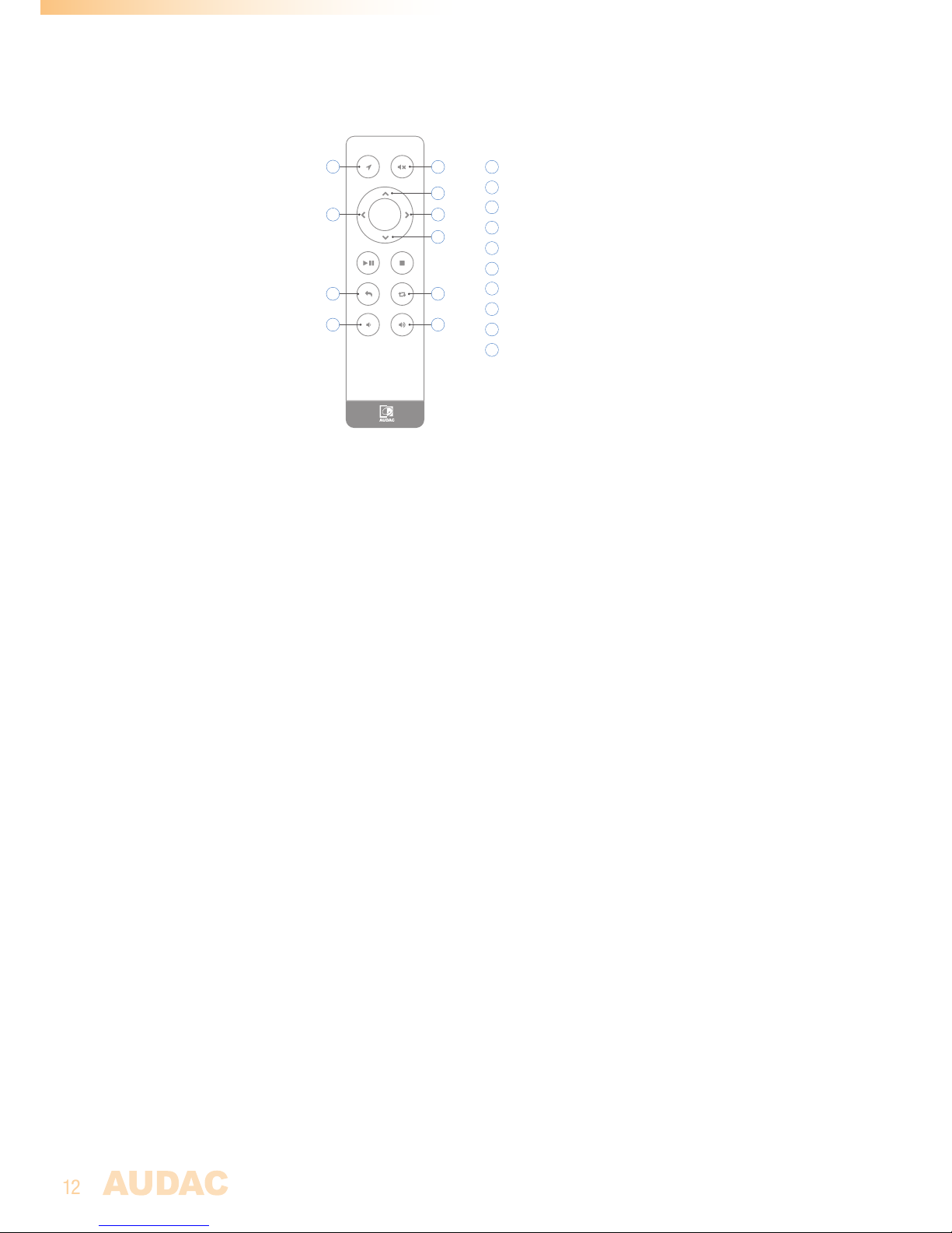
RMT40 Remote control overview (optional)
OK
2
5
7 8
6
1
2
3
4
5
6
7
8
Enter config mode
Mute
Volume down
Volume up
Level up
(Config mode only)
Level down
(Config mode only)
Previous speaker
(Config mode only)
Next speaker
(Config mode only)
9
10
9
Exit config mode
(Hold 1 second)
3
10
Recall default settings
(Hold 5 seconds)
4
1
(Hold 5 seconds)
RMT40 Remote control description
Mute (2):
Mutes (and unmutes) the overall system.
Volume down (3):
Decreases the overall volume for all channels simultaneously. The level is adjusted in steps
of 3 dB when momentary pressed, while larger adjustments are made when pressing and
holding.
Volume up (4):
Increases the overall volume for all channels simultaneously. The level is adjusted in steps of 3
dB when momentary pressed, while larger adjustments are made when pressing and holding.
Configuration mode:
Allows adjustment of the sound balance between all three amplifier channels (subwoofer,
left+right satellite, left satellite and right satellite). To enter the configuration mode, press and
hold the configuration button (1) for about 3 seconds. When configuration mode is entered,
a low frequency audio signal is heard through the integrated subwoofer.
Toggeling between the amplifier channels is possible by pressing the previous speaker (7)
or next speaker (8) buttons. A short tone is heard through the selected speaker.
Use the level up (5) and level down (6) buttons to adjust the level for the selected channel.
In default configuration, all channel settings are set to maximum. The level is adjusted in
steps of 3 dB when momentary pressed, while larger adjustments are made when pressing
and holding.
To exit the configuration mode, hold the enter config (1) or exit config (9) buttons for about
one second.
For factory defaults, hold the recall default settings (10) button for about 3 seconds. (only
when configuration mode is enabled)
Page 13
13
Chapter 3
Connecting the NOBA8A
NOTE
Make sure the mains power inlet is disconnected before any connections or wiring
adjustments are made. Disregarding this rule can lead to permanent damage of the
equipment.
2.1 mode (2-Way sub/top):
The NOBA8A is fixed configured in 3-Channel (2-way sub/top) mode. High-pass filters are
applied to the left & right output channels allowing connection of high/mid frequency speakers,
while a low pass filter is applied to the subwoofer channel driving the integrated speaker.
A default configuration is standard loaded, however specific speaker presets / configurations
can be loaded to optimize the settings depending of the selected speaker specifications. For
more information how specific presets have to be loaded, check chapter 4 of this instruction
manual.
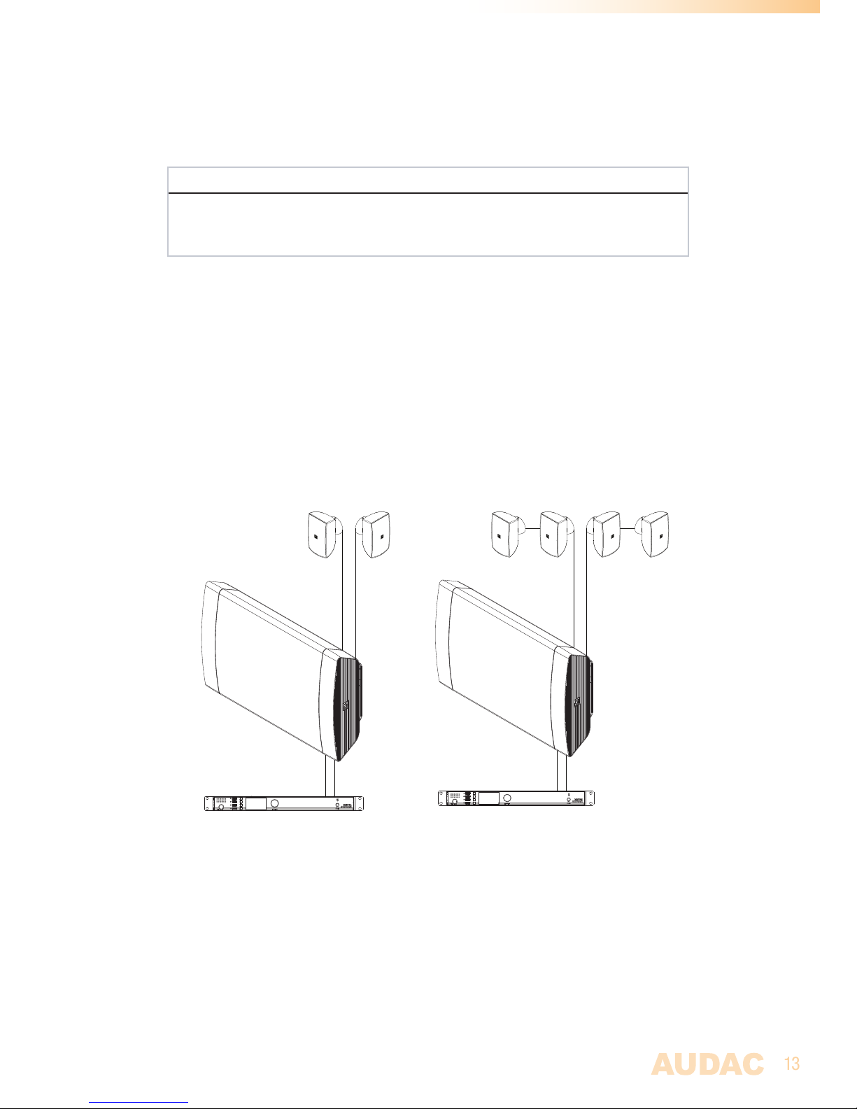
The following diagrams give an overview of specific setups with a NOBA8A and two of four
high/mid frequency loudspeakers.
Input R
Input L
Channel RChannel L
Channel R (1)Channel L (1)
Channel R (2)Channel L (2)
Input R
Input L
Typical NOBA8A configuration with audio
source and two high/mid frequency speakers
Typical NOBA8A configuration with audio
source and four high/mid frequency speakers
Page 14
14
Chapter 4
Loading presets & firmware updates
Loading WaveDynamics™ set solution configurations:
Complete set solution configuration files (*.SOL) containing parameters for optimal
performance and protection for the system can be loaded into the NOBA8A.
The files can be downloaded from the set solution page on the audac website (www.audac.
eu) and must be copied to an USB memory drive for insertion into the NOBA8A speaker. Make
sure the files are stored inside an ‘AUDAC’ subdirectory and the file extension is ‘*.SOL’. (The
file path should be ‘...\AUDAC\FILENAME.SOL’). It will search automatically for any available
‘*.SOL’ files. To guarantee the correct configuration is loaded, make sure only one ‘*.SOL’
file is available on the inserted memory drive.
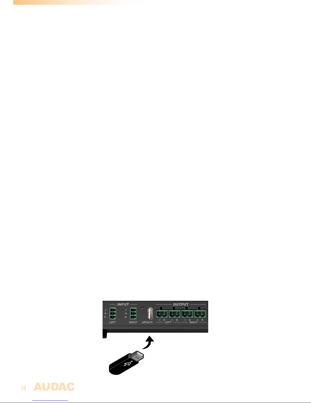
For loading the set solution configuration, simply insert the USB memory drive into the
‘Update’ USB slot on the NOBA8A connection panel. The configuration file will be automatically
discovered and loaded when stored in the correct path. The provided LED will blink when
the data transfer is active. Make sure the data transfer is complete (LED not blinking) before
the USB drive is removed.
Loading firmware updates:
Firmware updates can be made to the NOBA8A by copying them to an USB memory drive
and inserting them to the NOBA8A speaker. These updates are only required for servicing
and/or when implemented new functionalities to the system. They are not required to be
performed by the user.
The firmware update files can be downloaded through the Audac System Manager software
tool, and must be copied to an USB memory drive for insertion into the NOBA8A speaker.
Make sure the files are stored inside the root of the USB memory drive and the filename is
‘NOBA8.IMG’. (The complete file path should be ‘...\NOBA8.IMG’)
For loading the firmware update, simply insert the USB memory drive into the ‘Update’ USB
slot on the NOBA8A connection panel. The update file will be automatically discovered and
loaded when stored in the correct path. The provided LED will blink when the data transfer
is active. Make sure the data transfer is complete (LED not blinking) before the USB drive is
removed. Loading the firmware update can take several minutes before completed.
Page 15
15
Chapter 5
Mounting the NOBA8A
The NOBA8A comes standard delivered with a mounting bracket for on-wall installation.
The installation of this bracket shall be done according to a simple 5-step procedure as
described below:
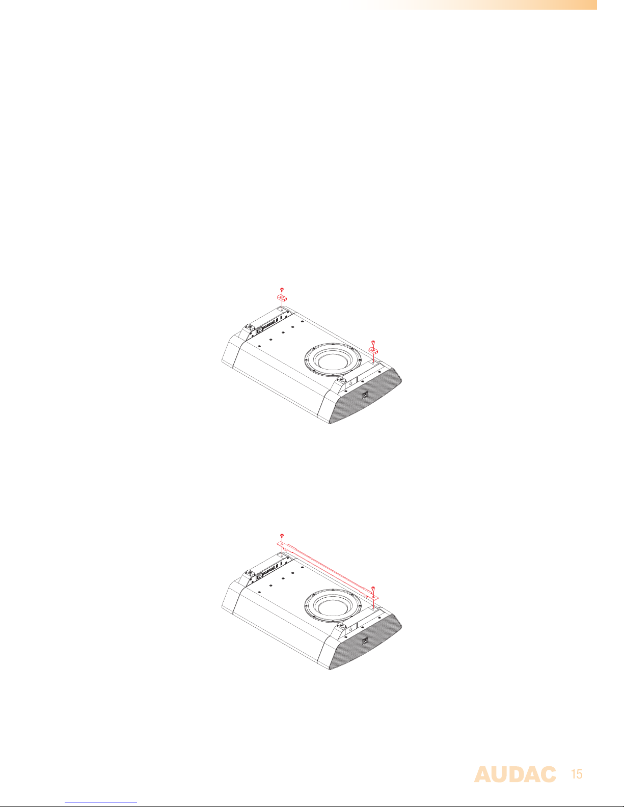
Step 1: Remove the rubber feet
The cabinet comes delivered with 4 pcs of rubber feet assembled supporting the cabinet
for floorstanding use. When installing the cabinet to the wall, two pcs of these rubber feet
must be removed for assembly of the supporting bar. Note that the cabinet can be mounted
in two directions. Depending of the required direction (position of the connections, amplifier
and bass port) both feet on the upper side needs to be removed. Keep the removed screws
for the next step.
Step 2: Assembling the cabinet supporting bar
Once both rubber feet are removed, the supporting bar for hooking the cabinet to the wall
plate needs to be assembled. Place the supporting bar on the position where both rubber
feet were located and fix it with the screws removed in step 1. Mind the mounting direction
when installing.
Page 16
16
Step 3: Mounting the wall plate
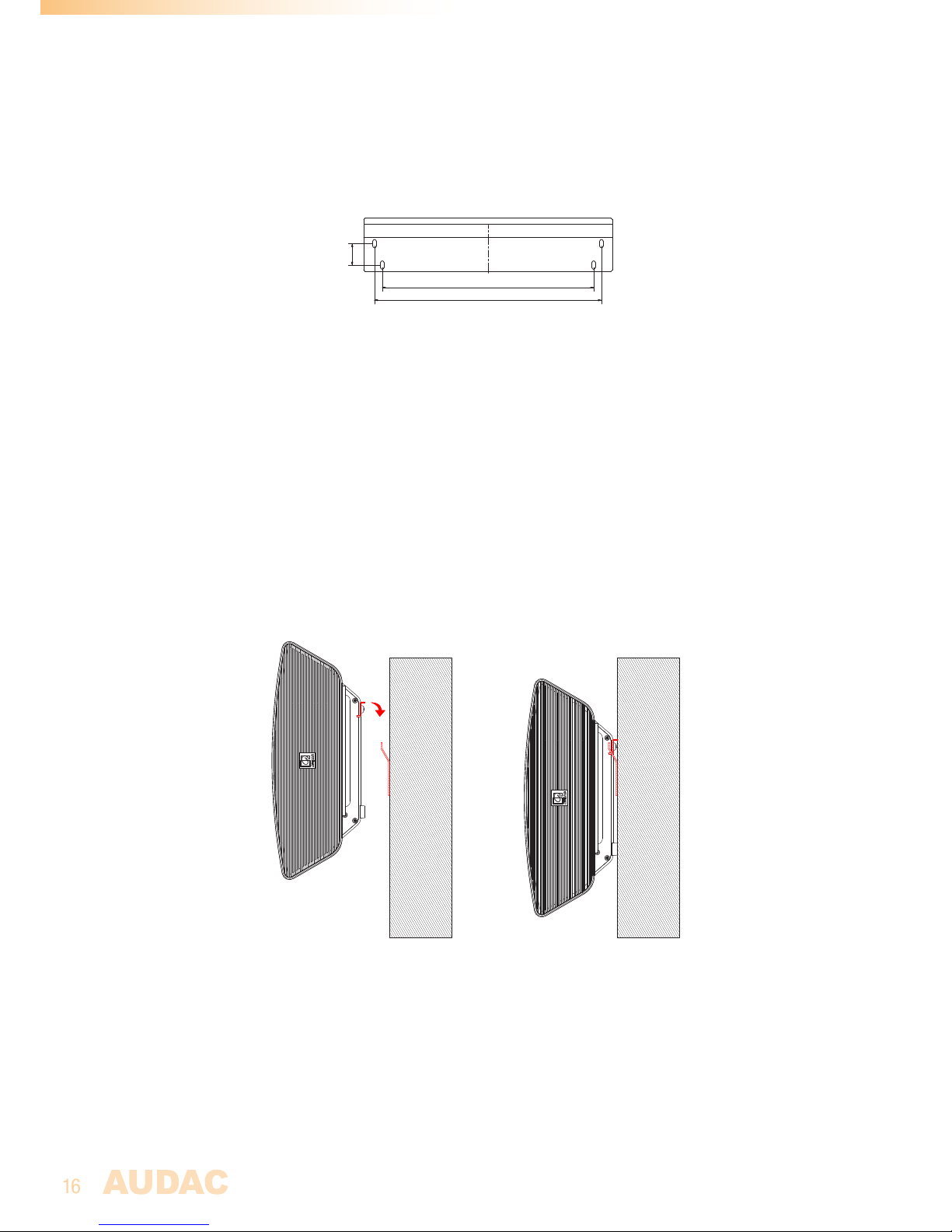
Mount the wall plate to the installation location of the NOBA8A. The wall plate has to be
fixed using four screws. The exact screw positioning is shown in the drawing below. The
used fasteners should be chosen depending on the mounting surface (brick, concrete, wood,
gypsum, ... ). Make sure the mounting surface can structurally support the weight of the
speaker.
340
365
3
4
,
5
Step 4: Connect the wiring
Once the wall plate is mounted, the wiring shall be connected before hooking the cabinet to
the wall plate. For more information how the connections should be made, check chapter 2
and chapter 3 of this instruction manual. When connecting, make sure all wiring is guided and
fixed properly so the loose wiring won’t touch any moving parts such as the speaker cone.
Step 5: Hook the cabinet to the wall plate:
The last step is hooking the cabinet to the wall plate. This is done by sliding the cabinet
support bar over the wall plate followed by a downwards movement of the loudpeaker, as
indicated in the drawing below.
Page 17

17
Chapter 6
Additional information
Technical specifications
Max power subwoofer 200 Watt
RMS power subwoofer 100 Watt
Sensitivity subwoofer (1W / 1m) 83 dB
Sound pressure (Max W / 1m) 105 dB
Frequency response ± 3 dB 90 Hz - 350 Hz
Frequency range -10 dB 45 Hz - 350 Hz
RMS power satellite @ 4 Ω 2 x 150 Watt
@ 8 Ω 2 x 75 Watt
Frequency response 20 Hz - 20 kHz (When no filter applied)
Signal to Noise ratio > 85 dB
Total Harmonic Distortion + Noise < 0.1%
Crosstalk > 100 dB
Inputs Type Balanced line
Connectors 3-pin terminal block (3.81 mm pitch)
Impedance 22 k Ω
Sensitivity 0 dB (1 V RMS)
Outputs Type Satellite loudspeaker output
Connectors 2-pin terminal block (5.08 mm pitch)
Controls Input gain (potentiometer)
RMT40 remote control (optional)
Indicators Standby, Signal, Clip
Cooling system Convection cooled
Amplifier technology Class-D
Power supply Type Switching mode
Range 100~240 V AC 50/60 Hz
Power consumption
All channels driven @ 1 kHz
No filter / crossover applied
Standby 0.7 Watt
Idle 22 Watt
1/8 Rated power 114 Watt
1/3 Rated power 259 Watt
Dimensions (W x H x D) 558 x 383 x 149 mm
Weight 9.75 Kg
Page 18

18
Accessories included Wall mount bracket
Optional accessories RMT40 RF remote control - 2.4 GHz
MBK410C Ceiling mount bracket
Page 19

19
Notes
Page 20

20
Notes
 Loading...