

Page 1

IMEO1
User Manual
www.audac.eu
Page 2

2
ADDITIONAL INFORMATION
This manual is put together with much care, and is as complete as could be on the
publication date. However, updates on the specifications, functionality or software
may have occurred since publication. To obtain the latest version of both manual and
software, please visit the Audac website @ www.audac.eu.
Page 3

3
Index
Introduction 5
Precautions 6
Safety requirements 6
Caution servicing 7
EC Declaration of Conformity 7
Waste of Electrical and Electronic Equipment (WEEE) 7
Bluetooth 7
Caution 8
Chapter 1: Connections and connectors 9
Connection standards 9
Chapter 2: Overview IMEO1 11
Front 11
Rear 12
Remote control 13
Chapter 3: Placement and mounting 15
Chapter 4: Connecting 18
Chapter 5: Additional information 21
Disable / enable specific functions 21
Technical specifications 22
Page 4

4
Page 5

5
Introduction
2.1 Soundbar
The IMEO1 Soundbar features a slim and elegant design and includes all required functions for expansion of any audiovisual system with an impressive sound, while having a
minimal hassle for installation. It’s perfectly suited for installations such as classrooms,
presentation rooms or meeting rooms where it can be used and installed in combination
with screens, smartboards or projectors.
The acoustics feature two 1.75” high frequency drivers with an RMS rating of 15 Watt
and a low frequency section composed of two 2.5” low frequency drivers with an RMS
rating of 30 Watt, resulting in an overall 60 Watt RMS rating. The Class-D amplifier with
integrated DSP processing and transmission line configuration for the low-frequency
drivers offers a crystal clear sound reproduction with stunning low-frequency response.
Selectable DSP presets offer optimization for applications such as presentations, music
playback or video’s.
Various input possibilities such as an unbalanced line input, HDMI (ARC) input or SPDIF
(optical and coaxial) allow compatibility with a variation of input sources, while Bluetooth allows wireless connections with portable devices.
An included IR remote control allows input selection, volume control and EQ preset selection while the unique and clever wall mounting bracket allows convenient mounting
to walls on any kind of surface or location with an optimal guiding and coverage for the
cables
Page 6

6
Precautions
READ FOLLOWING INSTRUCTIONS FOR YOUR OWN SAFETY
•
ALWAYS KEEP THESE INSTRUCTIONS FOR FUTURE REFERENCE. NEVER THROW
THEM AWAY
• ALWAYS HANDLE THIS UNIT WITH CARE
• CLEAN ONLY WITH DRY CLOTH
• HEED ALL WARNINGS AND FOLLOW ALL INSTRUCTIONS
•
NEVER EXPOSE THIS EQUIPMENT TO RAIN, MOISTURE, ANY DRIPPING OR
SPLASHING LIQUID. NEVER PLACE AN OBJECT FILLED WITH LIQUID ON TOP
OF THIS DEVICE
•
NO NAKED FLAME SOURCES, SUCH AS LIGHTED CANDLES, SHOULD BE PLACED
ON THE APPARATUS
• DO NOT INSTALL THIS UNIT NEAR ANY HEAT SOURCES SUCH AS RADIATORS
OR OTHER APPARATUS THAT PRODUCE HEAT
•
DO NOT PLACE THIS UNIT IN ENVIRONMENTS WITH A HIGH LEVEL OF DUST,
HEAT, MOISTURE OR VIBRATION
• THIS UNIT IS DEVELOPED FOR INDOOR USE ONLY. DO NOT USE IT OUTDOORS
• PLACE THE UNIT ON A STABLE BASE OR MOUNT IT IN A STABLE RACK
•
ONLY USE ATTACHMENTS & ACCESSORIES SPECIFIED BY THE MANUFACTURER.
•
UNPLUG THIS APPARATUS DURING LIGHTNING STORMS OR WHEN UNUSED
FOR LONG PERIODS OF TIME
•
CAREFULLY CHECK THE UNIT’S CONDITION AFTER UNPACKING.
IF THERE IS ANY DAMAGE TO THE CARTON BOX OR THE UNIT ITSELF, INFORM
YOUR VENDOR IMMEDIATELY.
•
ONLY CONNECT THIS UNIT TO A MAINS SOCKET OUTLET WITH PROTECTIVE
EARTHING CONNECTION
•
THE INSTALLATION, CONNECTION AND CONFIGURATION OF THE DEVICE
SHOULD BE DONE BY QUALIFIED TECHNICIANS
•
THE MAINS PLUG OR APPLIANCE COUPLER IS USED AS THE DISCONNECT
DEVICE, SO THE DISCONNECT DEVICE SHALL BE READILY OPERABLE
• USE THE APPARATUS ONLY IN MODERATE CLIMATES
Page 7
7
CAUTION - SERVICING
This product contains no user serviceable parts. Refer all servicing
to qualified service personnel. Do not perform any servicing
(unless you are qualified to do so.)
EC DECLARATION OF CONFORMITY
This product conforms to all the essential requirements and further
relevant specifications described in following directives: 2014/30/
EU (EMC) and 2014/35/EU (LVD)
WASTE ELECTRICAL AND ELECTRONIC EQUIPMENT (WEEE)
The WEEE marking indicates that this product should not be
disposed with regular household waste at the end of its product
life. This regulation is created to protect both the environment
and human health.
This product is developed and manufactured with high quality
materials and components which can be recycled and/or reused.
Please dispose of this product at your local collection point or
recycling centre for electrical and electronic waste. Do this to
make sure that the product is recycled in an environmental friendly
way, and help to protect the environment in which we all live.
BLUETOOTH
The Bluetooth® word mark and logos are registered trademarks
owned by Bluetooth SIG, Inc. We are the licensee to use such
marks. Other trademarks and trade names are those of their
respective owners.
Page 8
8
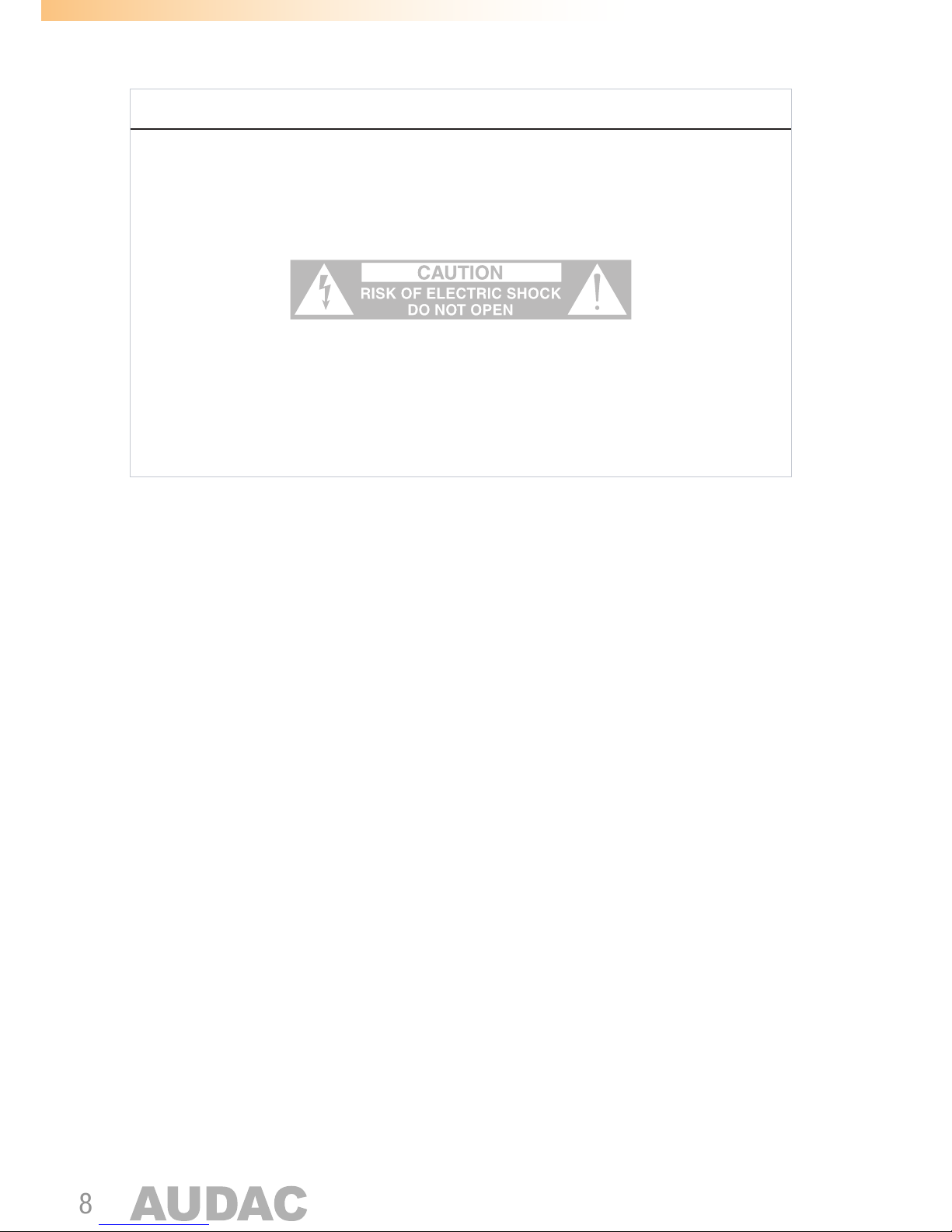
CAUTION
The symbols shown are internationally recognized symbols that warn about potential
hazards of electrical products. The lightning flash with arrow point in an equilateral
triangle means that the unit contains dangerous voltages. The exclamation point in
an equilateral triangle indicates that it is necessary for the user to refer to the users
manual.
These symbols warn that there are no user serviceable parts inside the unit. Do not
open the unit. Do not attempt to service the unit yourself. Refer all servicing to qualified
personnel. Opening the chassis for any reason will void the manufacturer’s warranty.
Do not get the unit wet. If liquid is spilled on the unit, shut it off immediately and take
it to a dealer for service. Disconnect the unit during storms to prevent damage.
Page 9
9
Chapter 1
Connections and connectors
CONNECTION STANDARDS
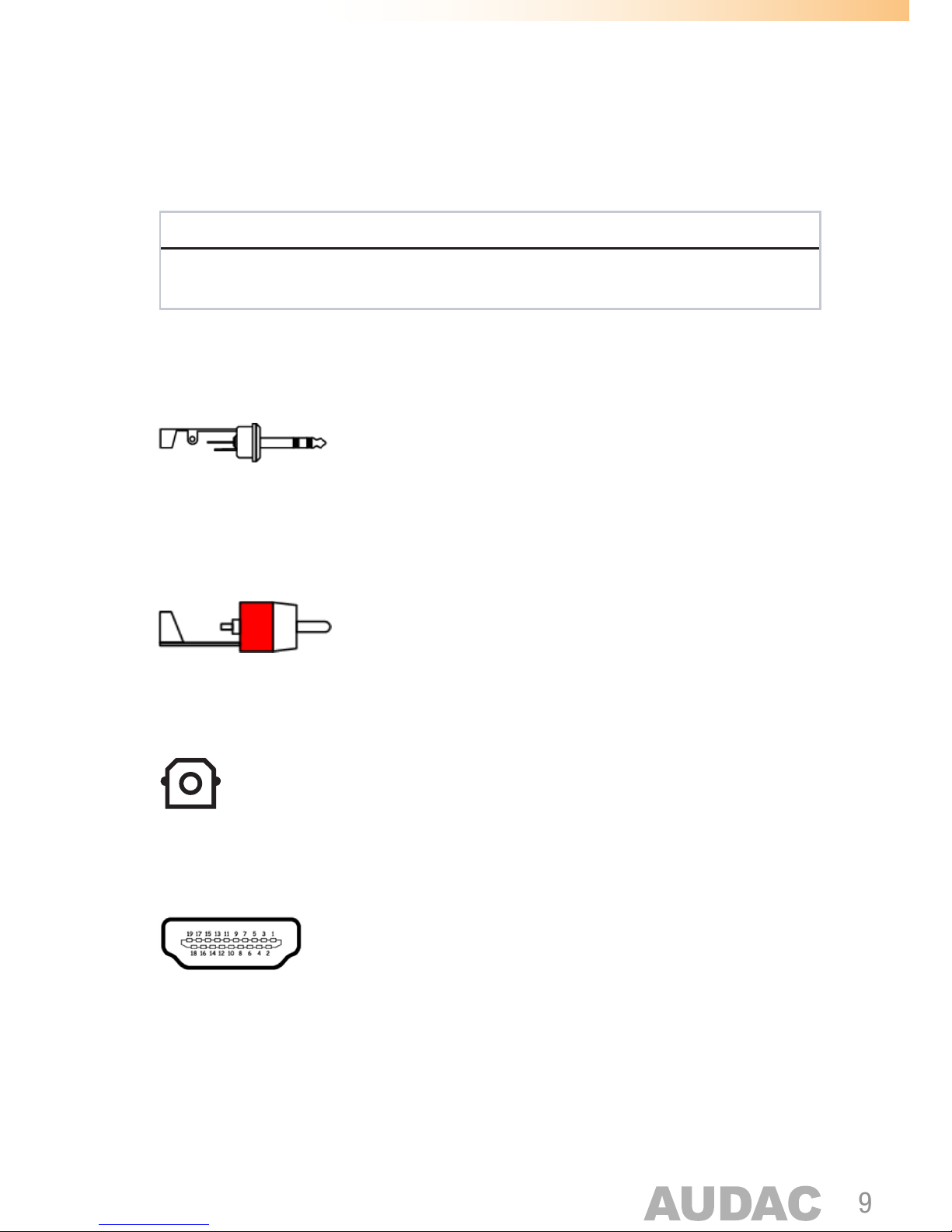
The in- and output connections for AUDAC audio equipment are performed
corresponding to international wiring standards for professional audio equipment.
3.5 mm Jack (AUX):
For unbalanced stereo line level input connections
Tip: Left
Ring: Right
Sleeve: Ground
RCA (COAXIAL):
For coaxial SP/DIF digital input connections
Tip: Signal
Sleeve: Ground
TOSLINK (OPTICAL)
For optical SP/DIF digital input connections
HDMI ARC
For HDMI (ARC) input connections
HDMI Type A (19-pin)
Pinout: According HDMI specification
Page 10

10
Page 11
11
Chapter 2
Overview IMEO1
Front
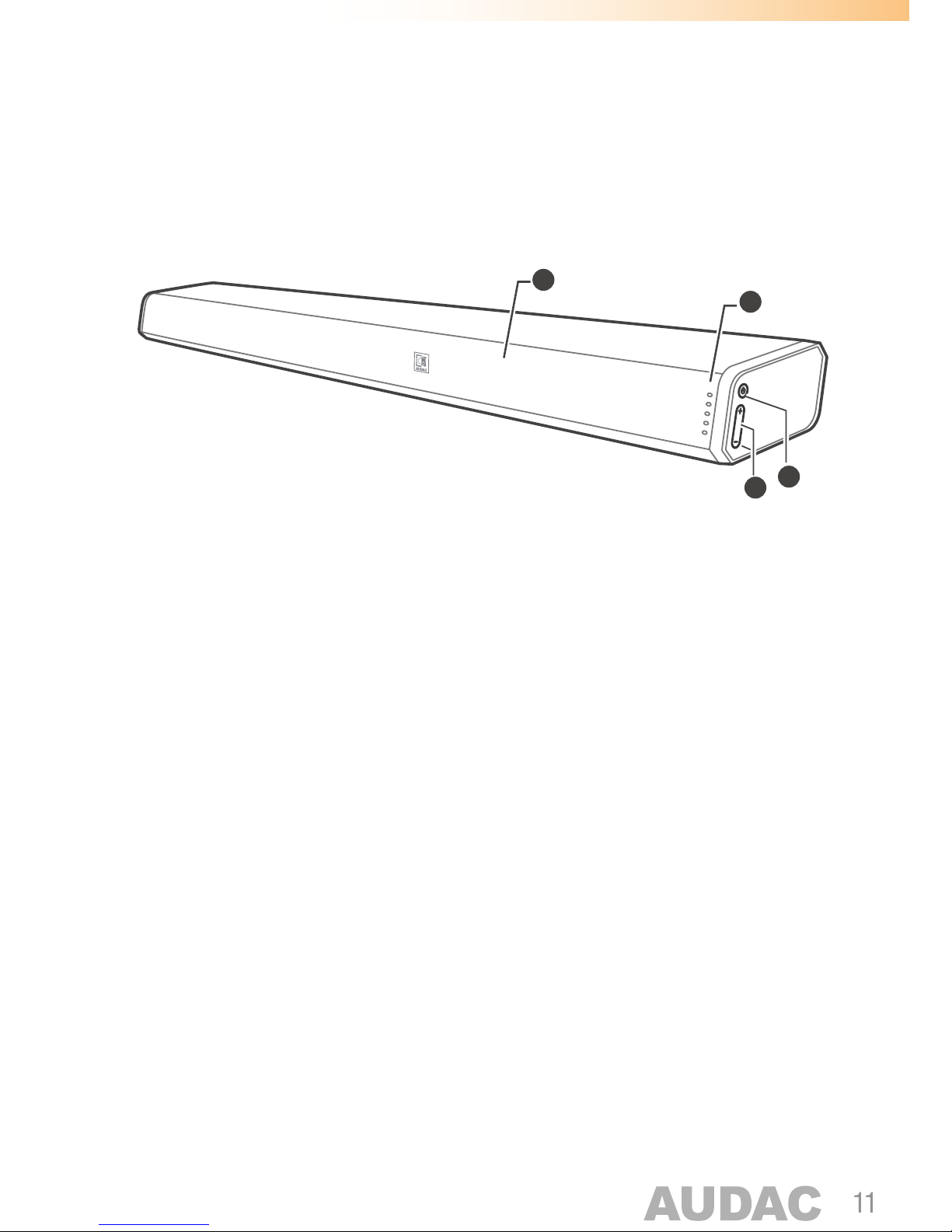
1) Status indicator LED’s:
These LED’s indicate the current operation status of the IMEO1.
Various color LED’s indicate following statuses:
• Red: Standby mode
• Green: AUX mode (3.5 mm jack input)
• Blue: Bluetooth mode
• Orange (Illuminated / Blinking): Optical / Coaxial mode
• White: HDMI ARC mode
2) Remote control (IR) sensor:
The remote control (IR) sensor is located behind the front grill of the IMEO1. This sensor
requires a line-of-sight connection with the remote control. Make sure this sensor is
not covered or blocked.
3) Power button:
The power button allows to switch on and off the unit.
Press to switch the sound bar on. Press and hold to switch the sound bar off.
Repeatedly press (short term) to switch between the various operation modes
(AUX / BLUETOOTH / OPTICAL / COAXIAL / HDMI ARC).
4) + / - buttons:
The + / - buttons allow to increase or decrease the volume level.
1
2
3
4
Page 12
12
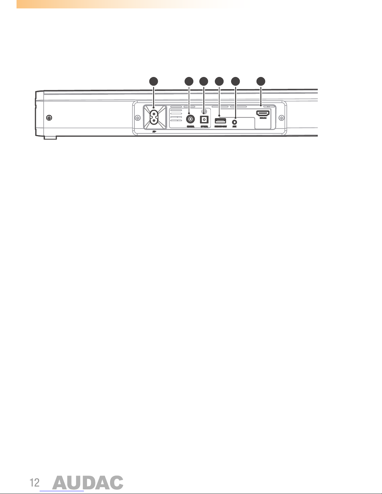
Rear
5) AC Power inlet connection:
The mains power supply (220-240V AC - 50/60 Hz) has to be applied to this AC power
inlet. The connection is made by an IEC C8 power connector and the power lead is
standard fitted, but can be unplugged for convenient assembly.
6) Coaxial input connection:
The coaxial input connection (RCA) allows connecting the sound bar to any TV, receiver
or other source device with an coaxial SP/DIF output connection.
7) Optical input connection:
The optical input connection (Toslink) allows connecting the sound bar to any TV, receiver
or other source device with an optical SP/DIF output connection.
8) Service only socket:
The USB socket is for service (programming) only. It is not designed for plugging in USB
memory drives, charging smartphones, tablets or similar devices.
9) AUX socket:
The AUX input connection (3.5 mm jack) allows connecting the sound bar to any stereo
line-level audio source. It can be a connection between a portable device such as
smartphone, tablet, laptop or headphone output of any device.
10) HDMI ARC socket:
The HDMI input socket allows connecting the soundbar to any TV or projector with an
HDMI connection supporting ARC functionality.
5 6 7 8 9 10
Page 13
13
Remote control
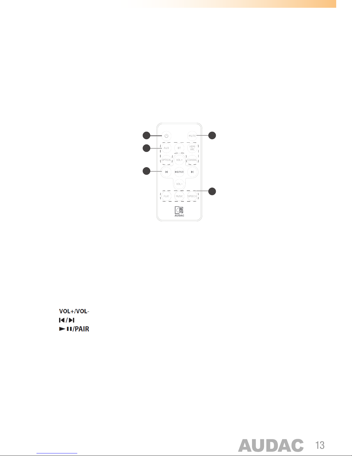
The IMEO1 includes an IR remote controller, which allows the operation of it from a
distance. The operation range of the remote controller is about 6 meters and shall be
operated without any obstacles between the remote control and the sound bar.
Below explanation gives an overview about the possible controls and their explanation.
1
2
5
3
4
1) Power button: Switches the sound bar between ON and STANDBY mode.
2) MUTE button: Toggles the status between Mute music or resume the sound.
3) Source buttons: Selects the audio source between the various operation modes:
AUX / BLUETOOTH / HDMI ARC / OPTICAL / COAXIAL.
4) Playback control buttons:
buttons: allows to increase or decrease the volume level.
buttons: allows to skip to the previous and next tracks (only in Bluetooth mode)
button: Allows to play / pause / resume playback in Bluetooth mode. Press
and hold to activate the pairing function in Bluetooth mode or disconnect the currently
paired Bluetooth device.
5) EQ buttons
Allows to select a preset sound effect. Various presets are available for FLAT, MUSIC
and SPEECH. The optimal flat configuration is selected when the FLAT preset (default
configured), while low frequencies are added when the MUSIC preset is selected and low
frequencies are reduced when selected the SPEECH preset. Select the optimal preset
according to your application requirements.
Page 14
14
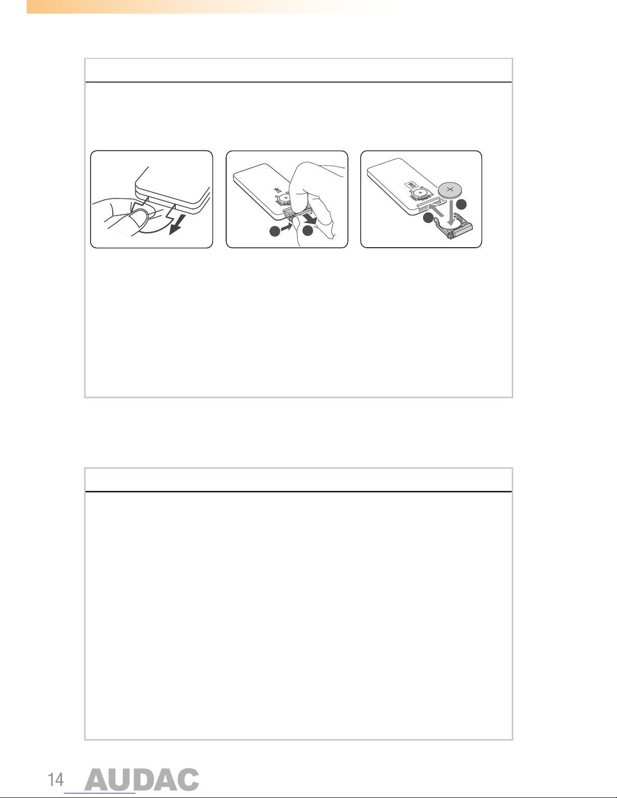
PREPARING THE REMOTE CONTROL
First time use:
The remote control has a pre-installed lithium CR2025 battery. Remove the protective
tab to activate the remote control battery.
4
3
1
2
4
Replace the remote control battery:
The remote control requires a CR2025, 3V Lithium battery.
To replace this battery, follow the steps as below:
• Push the tab on the side of the battery tray towards the tray
• Slide the battery tray out of the remote control
• Remove the old battery. Place a new CR2025 battery into the battery tray with
the correct polarity as indicated
• Slide the battery tray back into the slot in the remote control
ATTENTION
If the remote control is operated near other products which generate infrared rays,
or if other remote control units also using infrared rays are near the unit, it may
operate incorrectly. Conversely, the other products may operate incorrectly.
Precautions Concerning Batteries:
• Then the remote control is not to be used for a long time (more than a month),
remove the battery from the Remote Control to prevent it from leaking.
•
If the batteries leak, wipe away the leakage inside the battery compartment and
replace the batteries with new ones.
• Do not use any batteries other than those specified.
• Do not heat or disassemble batteries.
• Never throw them in fire or water.
• Do not carry or store batteries with other metallic objects. Doing so could cause
batteries to short circuit, leak or explode.
• Never recharge a battery unless it is confirmed to be a rechargeable type.
Page 15
15
Chapter 3
Placement and mounting
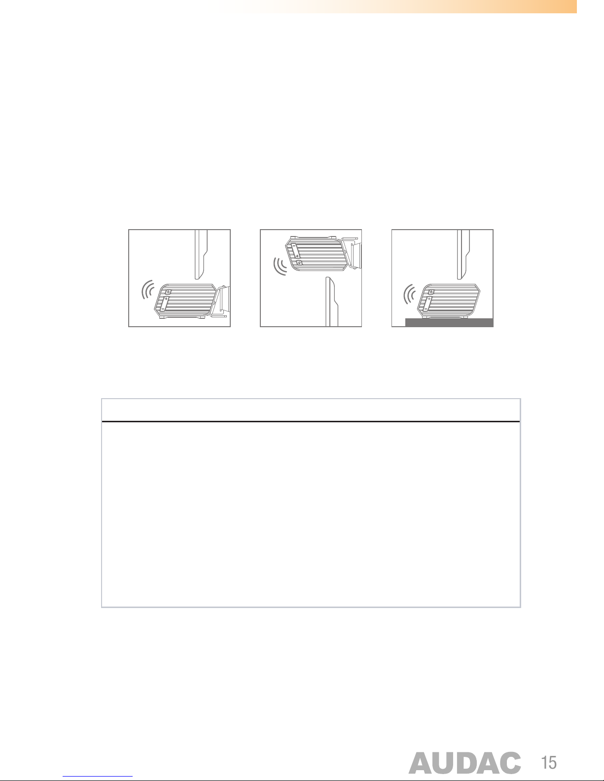
The IMEO1 offers possibilities for placement on a leveled surface underneath / in front
of the TV, display or projection surface. An included mounting bracket offers possibilities
for secure wall mounting, above or underneath the TV, display or projection surface.
Table
Standing
To p
Wall Mount
Bottom
Wall Mount
The special mounting bracket consists of a wall support bar and two fixation hooks which
comes default assembled to the sound bar.
ATTENTION
• Installation must be carried out by qualified personnel only.
• Incorrect assembly can result in severe personal injury and property damage (if
you intend to install this product yourself, you must check for installations such
as electrical wiring and plumbing that may be buried inside the wall).
•
It is the installer’s responsibility to verify that the wall will safely support the total
load of the unit and wall brackets.
• Additional tools (not included) are required for the installation.
• Do not overtighten screws.
• Keep this instruction manual for future reference.
Page 16
16
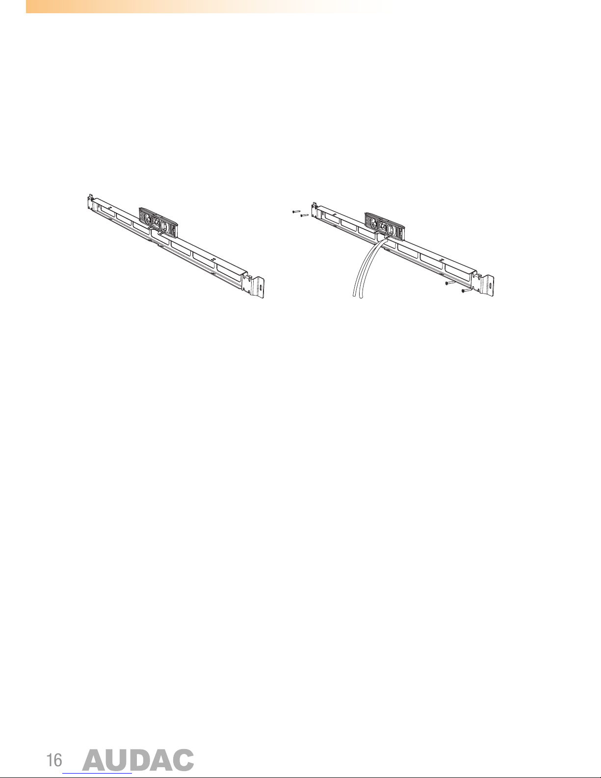
Step 1: Attach the wall support bar
The first step is the mounting of the supplied wall support bar on the desired location on
the wall. The support bar has to be fixed to the wall by four screws which need to get
fitted through the provided slots. The provided slots have an elliptical shape, allowing
the possibility for slightly adjusting the position to make it perfectly level.
Make sure the appropriate fasteners are used, depending on the mounting surface
(brick, concrete, wood, ... )
The cables (depending of the required connections for applications) can be fed through
the openings of the wall support bar, and can be tied to the fixation slots using cable ties.
Step 2: Make the connections
After the wall support bar is mounted, the connections shall be made depending of the
application requirements. Various connection accessories such as cables, pigtails and
90° angle parts are included for making the connection possible.
Page 17
17
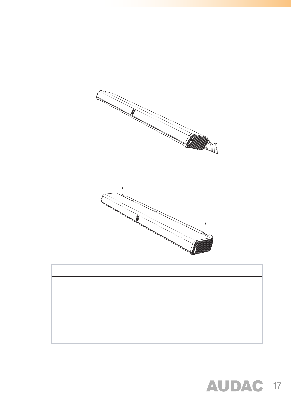
Step 3: Attach the speaker
After the wall support bar is attached and the connections are made, the soundbar shall
be fixed to the wall plate. This is done by sliding the hooks assembled to the soundbar
into the provided slots on the wall support bar and fixing them.
To prevent the soundbar from falling down, the security screw on top of the fixation
hooks shall be tightened.
NOTE
The wall bracket for the IMEO1 speakers is designed in such way that the speaker can
be hooked onto it in two directions. The normal direction (speakers facing upwards) is
used when the soundbar is positioned underneath the TV, display or projection surface.
The reversed direction (speakers facing downwards) is used when the soundbar is
positioned above it.
When mounted in reversed direction, the logo on the front grill can be rotated through
pulling it out of the recess and turning it.
Page 18
18
Chapter 4
Connecting
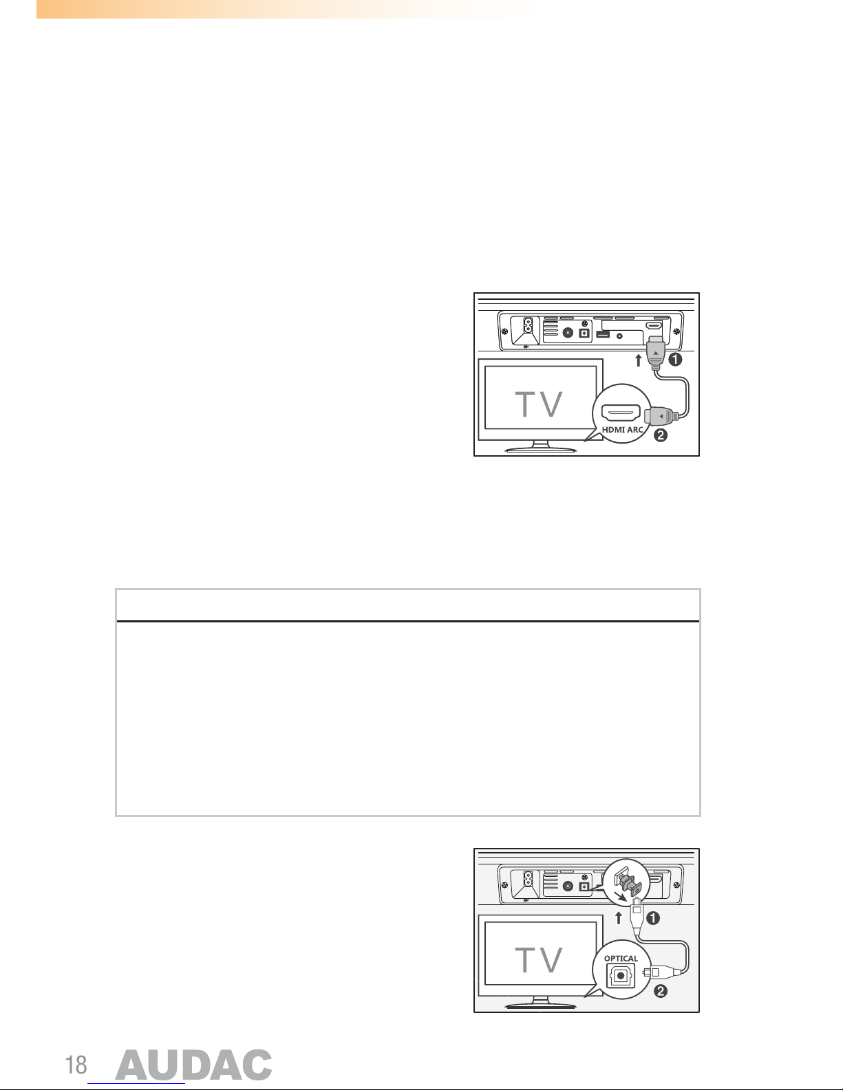
Using the HDMI (ARC) socket
The ARC (Audio Return Channel) function allows you
to send audio from your ARC compliant TV to your
sound bar through a single HDMI link. To enjoy the
ARC function, please ensure your TV is both HDMI
CEC and ARC compliant and set up accordingly.
When correctly set up, you can use your TV remote
control to adjust the volume output (VOL +/- and
MUTE) of the sound bar. - Connect the HDMI cable
(not included) from unit’s HDMI (ARC) socket to the
HDMI (ARC) socket on your ARC compliant TV.
Then press the remote control to select HDMI ARC mode.
NOTE
•
Your TV must support the HDMI-CEC and ARC and the HDMI-CEC and ARC
must be set to On.
• The setting method of HDMI-CEC and ARC may differ depending on the TV. For
details about ARC function, please refer to the owner’s manual.
• Ensure that you use an HDMI cables that can support the ARC function.
•
HDMI-CEC will be called different names by various manufacturers – please refer
to your owner’s manual for details on setting up HDMI-CEC and ARC.
Using the optical socket
The optical socket allows connection of the sound
bar to the optical output of your TV or receiver.
Simply connect using an optical (Toslink) cable.
Remove the protective cap before connecting.
SERVICE ON LY
HDMI ARC
OPTICALCOAXIAL AUXSERVICE ON LY
HDMI ARC
OPTICALCOAXIAL AUX
SERVICE ON LY
HDMI ARC
OPTICALCOAXIAL AUX
Page 19
19
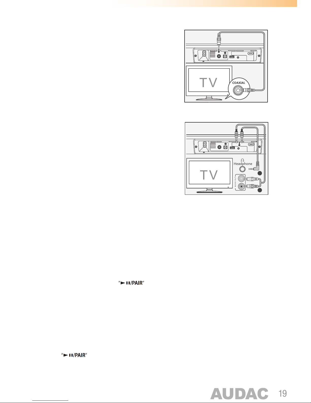
Using the coaxial socket
The coaxial socket allows connection of the sound
bar to the coaxial output of your TV or receiver.
Simply connect using a 75 Ohm coaxial cable.
Using the AUX socket
The AUX socket allows connection of the sound bar
to any device with an unbalanced stereo line output,
such as TV, computer, laptop, smartphone, tablet, ...
Depending of the output of the connected device
3.5 mm jack (A) or RCA (B), the appropriate cable
shall be used.
Using Bluetooth
The first time when your Bluetooth portable device is connected (smartphone, tablet, ...
) it needs to get paired. For getting it paired, the sound bar shall be switched ON and in
Bluetooth mode. This can be done using the power button on the side of the unit, or the
remote control. When in Bluetooth mode, the blue LED behind the front grill will blink.
Activate the Bluetooth mode in your portable device and search for devices. The device
name ‘AUDAC IMEO1’ will appear on your Bluetooth device list. If the device can’t be
found, press and hold the button on the remote control to be discoverable.
The system will enter in pairing mode and ‘Pairing’ will be heard through the speakers.
The Bluetooth indicator (blue LED) will blink fast.
Select ‘AUDAC IMEO1’ from the device list and ‘Paired’ will be heard through the speakers.
The Bluetooth indicator (blue LED) will illuminate constantly.
Disconnecting the Bluetooth function can be done by switching to another function (input)
on the unit, disabling the Bluetooth from your portable device, or pressing and holding
the button on the remote control.
SERVICE ON LY
HDMI ARC
OPTICALCOAXIAL AUX
SERVICE ON LY
HDMI ARC
OPTICALCOAXIAL AUX
SERVICE ON LY
HDMI ARC
OPTICALCOAXIAL AUX
A
B
SERVICE ON LY
HDMI ARC
OPTICALCOAXIAL AUX
Page 20

20
NOTE
•
The operation range between the sound bar device and the Bluetooth transmitter
(smartphone, tablet, ... ) is approximately 8 meters. (without any object in between)
• Before any Bluetooth device is connected, ensure you know its capabilities
• Compatibility with all Bluetooth devices is not guaranteed
•
Any obstacle in between the sound bar and the Bluetooth transmitter can reduce
the operational range
•
If the signal strength is weak, the sound bar will disconnect automatically, but
will re-enter pairing mode automatically.
Page 21

21
Chapter 5
Additional information
Disable / enable specific functions
In projects with public system access such as classrooms or conference rooms, it can
be desirable to lock it in a specific operation (input) mode or disable specific functions,
to avoid users changing the input signal.
Lock input:
To lock the sound bar in a specific input function (disable the operation mode selection),
turn the unit ON and switch to the desired audio source (e.g. AUX input). Press and hold
the ‘AUX’ button (or other selected function) on the remote control for about 5 seconds
to enable the lock. All status indicator LED’s will blink now simultaneous and the input
selection will be locked. (the input can’t be changed by the user).
Press and hold the selected function button again for about 5 seconds to disable the
lock. All status indicator LED’s will blink again simultaneous and the lock will be disabled.
Disable Bluetooth:
To disable the Bluetooth function, make sure the unit is in standby mode and press
and hold the BT button on the remote control for about 5 seconds. The blue Bluetooth
indicator LED will blink and the Bluetooth function will be disabled.
Press and hold the BT button again for about 5 seconds in standby mode to enable the
Bluetooth function again. The blue Bluetooth indicator LED will blink and the Bluetooth
function will be enabled again.
Page 22

22
Technical specifications
Inputs Type Stereo unbalanced line (AUX)
Connectors 3.5 mm jack connector
Sensitivity 500 mV
Type Coaxial SP/DIF digital input
Connectors RCA
Type Optical SP/DIF digital input
Connectors Toslink
Type HDMI ARC
Connectors HDMI 19-pin
Output power 2 x 15 Watt (Left & Right)
30 Watt (Subwoofer)
Frequency response 40 Hz - 20 kHz
THD+N 1 % (1 kHz, 1W)
Bluetooth Version V3.0
Max power Tx < 7 dBm
Frequency band 2402 MHz - 2480 MHz
Remote control Distance 6 m
Angle 30°
Battery type CR2025
Power consumption Standby 0.5 Watt
Nominal 30 Watt
Power supply 220 - 240 V AC / 50 - 60 Hz
Dimensions (W x H x D) 1000 x 60 x 113 mm
Weight 3.6 Kg
Packaging Carton box
Shipping weight & Volume 4.5 Kg - 0.022 Cbm
Page 23

23
Accessories included Remote control (IR)
3.5 mm audio cable
3.5 mm audio pigtail
90° HDMI angle adapter
Wall mounting bracket
User manual
Page 24

24
Notes
 Loading...